teaching circuit design and measurements - high impact tec
TRANSCRIPT
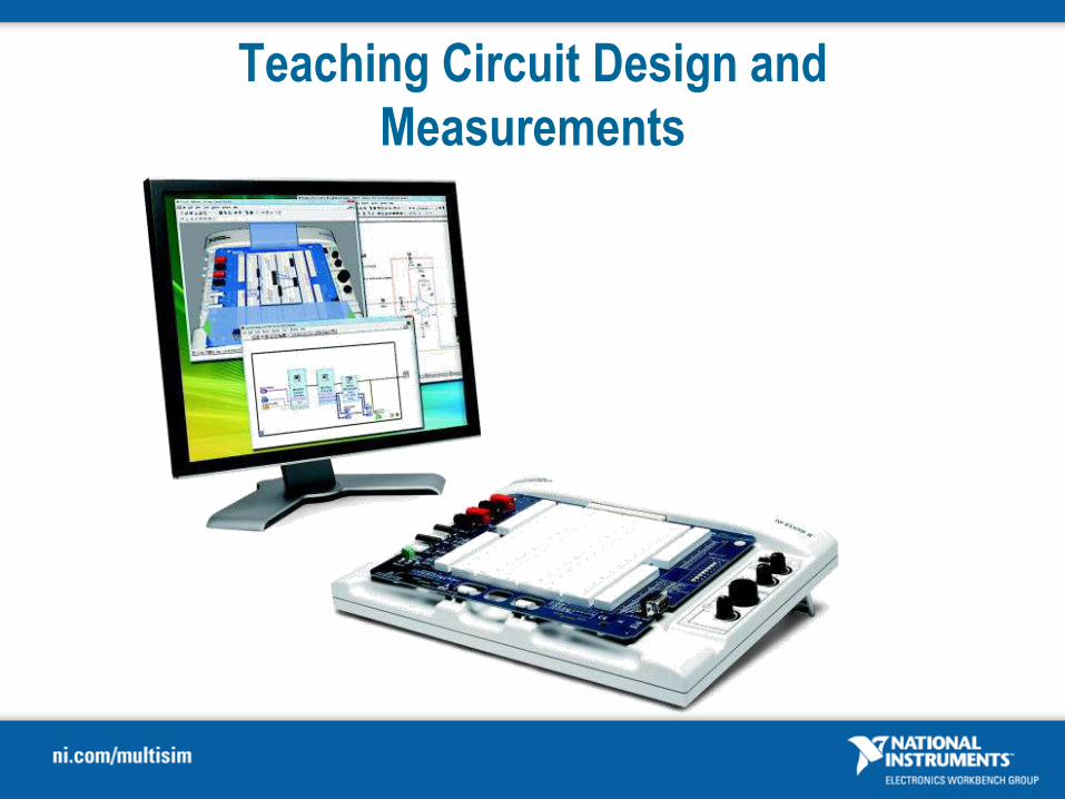
Teaching Circuit Design and
Measurements

2
Course Materials
Software
• NI Multisim 11.0
• NI ELVISmx 4.1.1 driver
• NI LabVIEW 8.5 or later
Hardware
• NI ELVIS II/II+
• Components & Wire
Manual /Files
• Exercises printed material
• Sample Circuit Files
3
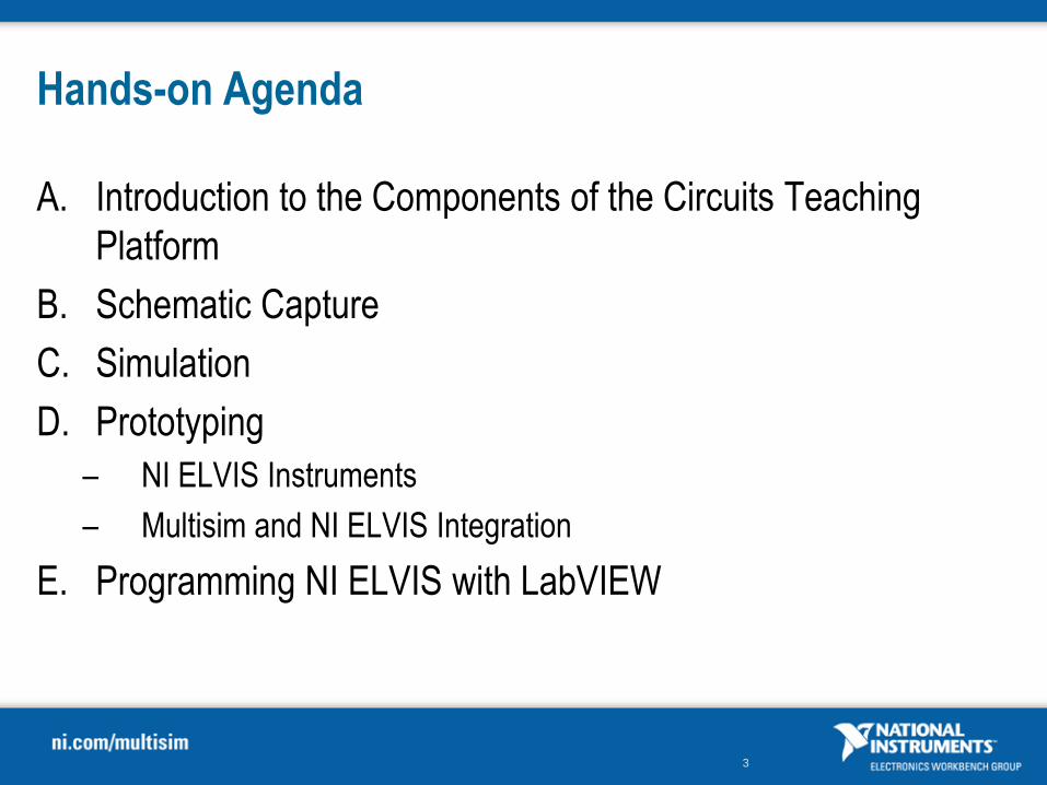
Hands-on Agenda
A. Introduction to the Components of the Circuits Teaching
Platform
B. Schematic Capture
C. Simulation
D. Prototyping
– NI ELVIS Instruments
– Multisim and NI ELVIS Integration
E. Programming NI ELVIS with LabVIEW
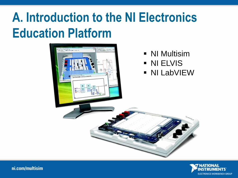
A. Introduction to the NI Electronics
Education Platform
NI Multisim
NI ELVIS
NI LabVIEW

5
A. NI Electronics Education Platform
Electronics Education Platform
National Instruments tools address challenges of circuit education

National Instruments | Circuit Design Suite
National Instruments Circuit Education Platform
NI Multisim
A unified environment for the design and
simulation
NI Ultiboard
Prototype CAD design implemented
7
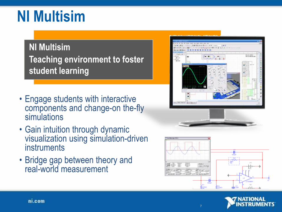
NI Multisim
NI Multisim
Teaching environment to foster
student learning
• Engage students with interactive components and change-on the-fly simulations
• Gain intuition through dynamic visualization using simulation-driven instruments
• Bridge gap between theory and real-world measurement

8
22 Virtual
Instruments
behaving like
real-world
counterparts
Advanced
Analyses to
investigate circuit
characteristics
Teach
troubleshooting
with circuit
restrictions and
hidden faults
15,000+
Components to
reinforce theory
Core NI Multisim Educational Features

9
Multisim Teaching Environment
• NI Multisim SPICE-based simulation
Analog, digital, mixed
Interactive parts
Virtual instruments
Circuit faults and restrictions
• Integration with NI ELVIS II/II+ 3D virtual breadboard
NI ELVIS instruments
Input/output of real-world signals
10
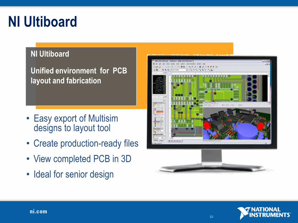
• Easy export of Multisim designs to layout tool
• Create production-ready files
• View completed PCB in 3D
• Ideal for senior design
NI Ultiboard
NI Ultiboard
Unified environment for PCB
layout and fabrication
11
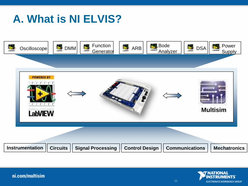
MechatronicsCircuits Control Design Communications
DMMOscilloscopeFunction
GeneratorARB DSA
Bode
AnalyzerPower
Supply
Instrumentation Signal Processing
A. What is NI ELVIS?
Multisim
14
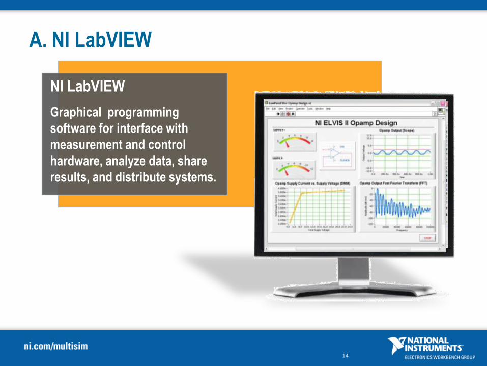
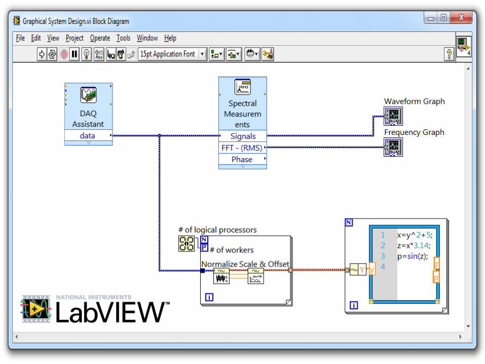
A. NI LabVIEW
NI LabVIEW
Graphical programming
software for interface with
measurement and control
hardware, analyze data, share
results, and distribute systems.

15
Teaching Circuits
Step 1: Capture, Simulate and
improve a design in NI Multisim
Step 2. Build circuit and measure
Real-world signals with NI ELVISStep 3. Compare Simulated vs.
Real Measurement Data
Compare
Recognize and Learn

16
Teaching Circuits | Series RLC
Step 1: Capture, Simulate and understand a design in NI Multisim
C4100nF
L1470µH
RL17.9Ω
Sig na l IN
Sig na l OUT
GND
XFG1XBP1
IN OUT
XSC1
A B
Ext Trig+
+
_
_ + _
17
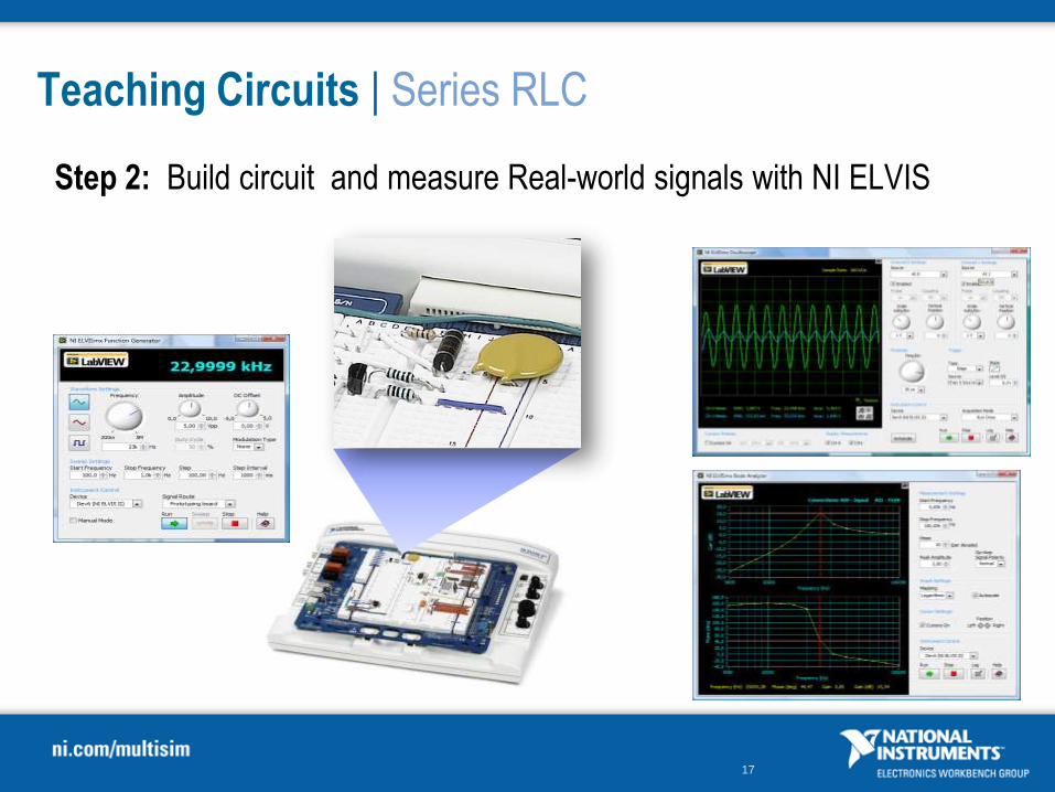
Teaching Circuits | Series RLC
Step 2: Build circuit and measure Real-world signals with NI ELVIS
18
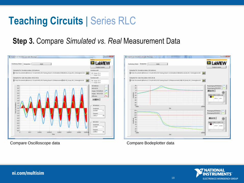
Teaching Circuits | Series RLC
Step 3. Compare Simulated vs. Real Measurement Data
Compare Oscilloscope data Compare Bodeplotter data
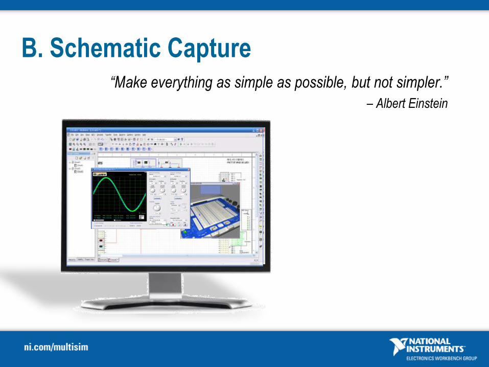
B. Schematic Capture“Make everything as simple as possible, but not simpler.”
– Albert Einstein

20
B. What is NI Multisim?
Unified environment for teaching circuit
theory and design through capture and
simulation
Analysis
Simulate
Capture
21
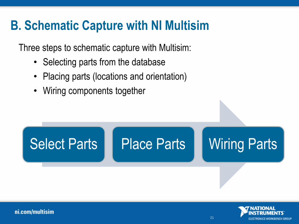
B. Schematic Capture with NI Multisim
Three steps to schematic capture with Multisim:
• Selecting parts from the database
• Placing parts (locations and orientation)
• Wiring components together
Select Parts Place Parts Wiring Parts

29
DEMO
Multisim Environment
Objective:
Familiarize with Multisim environment
Select Components from Component
Place components
Wire circuit
Goa
l
30
Exercise 1
Schematic Capture
Approximate time to complete: 15 minutes
Objective:
Finding and placing parts for 741 Circuit
Familiarize with Multisim environment
Select Components
Place components
Wire circuit
Goa
l

C. Simulating Circuits
“Computer programs provide a cost-effective means of
confirming intended operation”
-Dr. Gordon RobertsAuthor of SPICE – Second Edition

32
C. Simulation
Definition:
Simulation is a mathematical way of emulating
the behavior of a circuit.
Benefit:
Simulation can determine a circuit’s performance
without physically constructing the circuit or using
actual test instruments.
• incorporates SPICE3F5 and XSPICE at the
core of its simulation engine
• non-SPICE-standard Cadence® PSpice®
compatibility features
Analysis
Simulate
Capture

33
C. Simulation in Multisim
Simulation Toolbar
MCU Simulation Options
Stop Simulation
Pause Simulation
Start Simulation
Method 1 – Interactive SPICE Simulation Method 2 – SPICE Analyses
Interactive Simulation Status
34
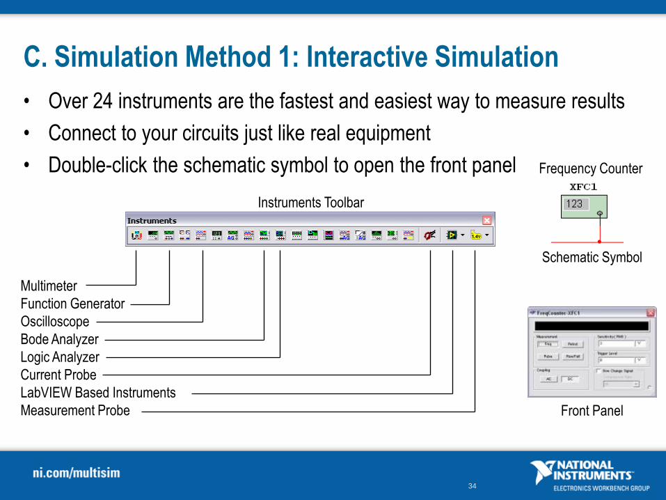
C. Simulation Method 1: Interactive Simulation
• Over 24 instruments are the fastest and easiest way to measure results
• Connect to your circuits just like real equipment
• Double-click the schematic symbol to open the front panel
Multimeter
Function Generator
Oscilloscope
Bode Analyzer
Logic Analyzer
Current Probe
LabVIEW Based Instruments
Measurement Probe
Instruments Toolbar
Front Panel
Schematic Symbol
Frequency Counter

35
C. Method 1 – Using Instruments in Circuits
1. Access instruments from Design Bar
2. Placing instruments in circuit
• Multiple Instruments
• Connect
42
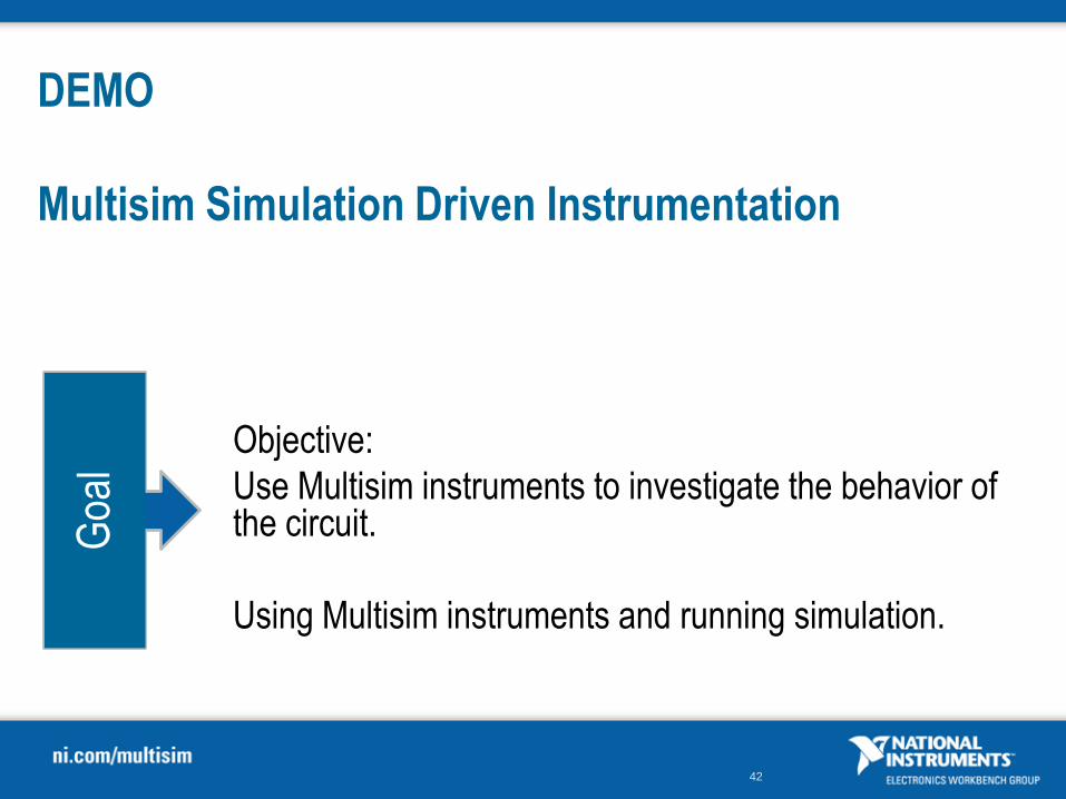
DEMO
Multisim Simulation Driven Instrumentation
Objective:
Use Multisim instruments to investigate the behavior of the circuit.
Using Multisim instruments and running simulation.
Goa
l
43
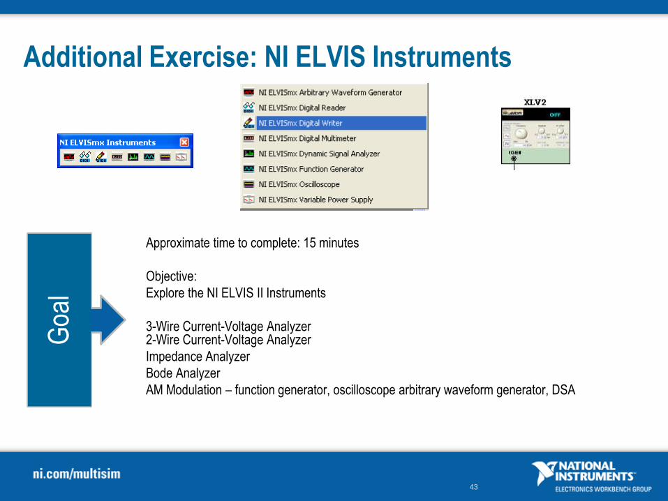
Additional Exercise: NI ELVIS Instruments
Approximate time to complete: 15 minutes
Objective:
Explore the NI ELVIS II Instruments
3-Wire Current-Voltage Analyzer2-Wire Current-Voltage Analyzer
Impedance Analyzer
Bode Analyzer
AM Modulation – function generator, oscilloscope arbitrary waveform generator, DSA
Goa
l

44
Exercise 2
Simulating Circuits
Approximate time to complete: 15 minutes
Objective:
Use Multisim instruments to investigate the behavior of the circuit.
Using Multisim instruments and running simulation.
Goa
l
45
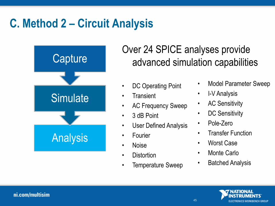
C. Method 2 – Circuit Analysis
Over 24 SPICE analyses provide
advanced simulation capabilities
Analysis
Simulate
Capture
• DC Operating Point
• Transient
• AC Frequency Sweep
• 3 dB Point
• User Defined Analysis
• Fourier
• Noise
• Distortion
• Temperature Sweep
• Model Parameter Sweep
• I-V Analysis
• AC Sensitivity
• DC Sensitivity
• Pole-Zero
• Transfer Function
• Worst Case
• Monte Carlo
• Batched Analysis

46
C. Method 2 – Circuit Analyses
• Each Analyses has an intuitive configuration wizard
Configuration Dialog Output Control
52
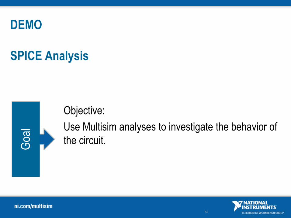
DEMO
SPICE Analysis
Objective:
Use Multisim analyses to investigate the behavior of
the circuit.
Goa
l
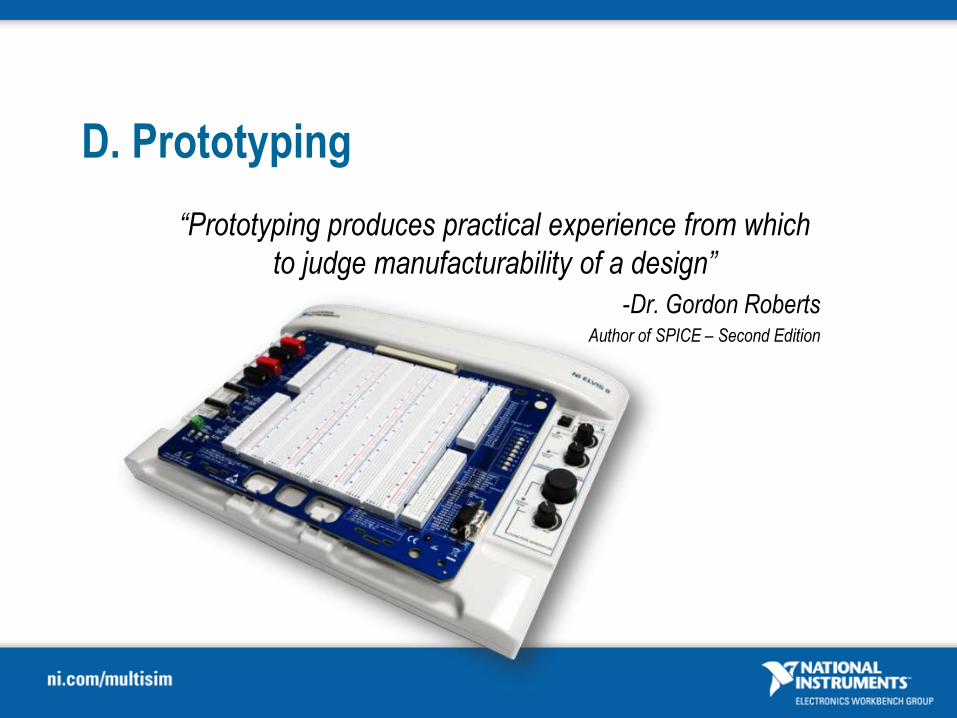
D. Prototyping
“Prototyping produces practical experience from which
to judge manufacturability of a design”
-Dr. Gordon RobertsAuthor of SPICE – Second Edition
54
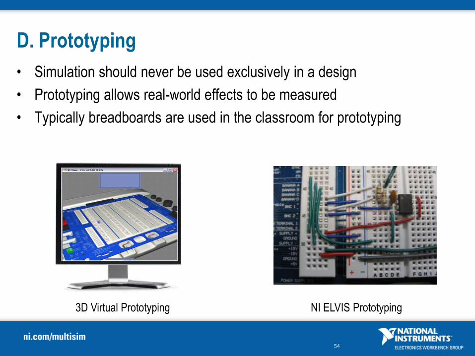
D. Prototyping
• Simulation should never be used exclusively in a design
• Prototyping allows real-world effects to be measured
• Typically breadboards are used in the classroom for prototyping
3D Virtual Prototyping NI ELVIS Prototyping
55
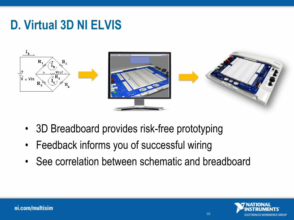
D. Virtual 3D NI ELVIS
• 3D Breadboard provides risk-free prototyping
• Feedback informs you of successful wiring
• See correlation between schematic and breadboard

56
• 12 computer-based LabVIEW Virtual Instruments
• Hi-speed USB plug-and-play connectivity
• Prototyping Breadboard
D. Prototyping with NI ELVIS
NI ELVIS WorkstationOscilloscope
Function Generator
57
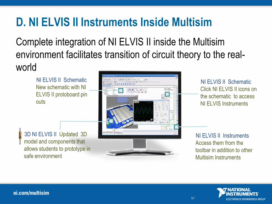
D. NI ELVIS II Instruments Inside Multisim
Complete integration of NI ELVIS II inside the Multisim
environment facilitates transition of circuit theory to the real-
world
3D NI ELVIS II Updated 3D
model and components that
allows students to prototype in
safe environment
NI ELVIS II Schematic
Click NI ELVIS II icons on
the schematic to access
NI ELVIS Instruments
NI ELVIS II Instruments
Access them from the
toolbar in addition to other
Multisim Instruments
NI ELVIS II Schematic
New schematic with NI
ELVIS II protoboard pin
outs

58
D. Theory and Measurement
Compare simulated data and measured signal on the same instrument
Access NI ELVIS
hardware With one
click switch between
simulated signals and
acquiring signals from
your NI ELVIS II
hardware
NI ELVIS II Instruments Compare simulated
Multisim data with measured signals from NI ELVIS
II within Multisim

60
Exercise 3
Prototyping and Measurements
Approximate time to complete: 15 minutes
Objective:
DEMO: Explore the 3D Multisim environment.
Use NI ELVIS hardware to test and measure design.
Goa
l

Additional Supplement
Digital Electronics & VHDL
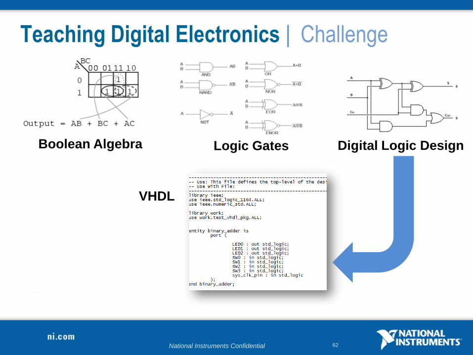
National Instruments Confidential 62
Boolean Algebra Logic Gates Digital Logic Design
VHDL
Teaching Digital Electronics | Challenge
National Instruments Confidential 63
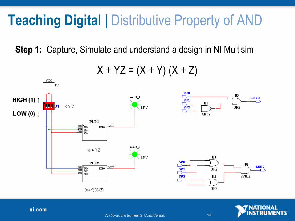
Teaching Digital | Distributive Property of AND
Step 1: Capture, Simulate and understand a design in NI Multisim
X + YZ = (X + Y) (X + Z)
National Instruments Confidential 64
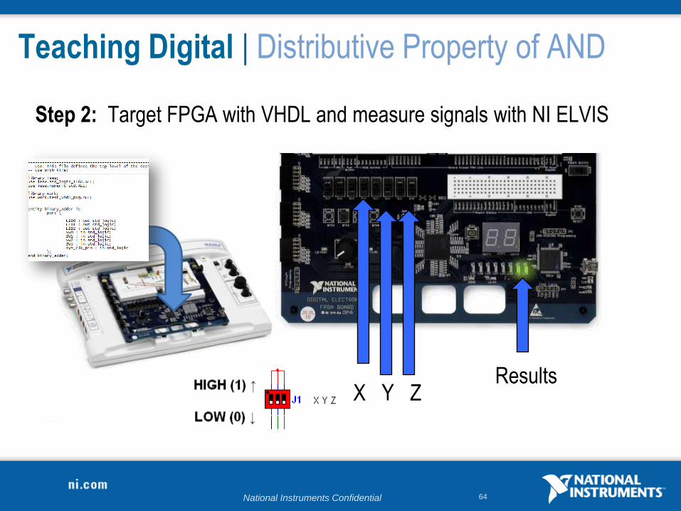
Teaching Digital | Distributive Property of AND
Step 2: Target FPGA with VHDL and measure signals with NI ELVIS
X Y ZResults
National Instruments Confidential 65
Teaching Digital | Distributive Property of AND
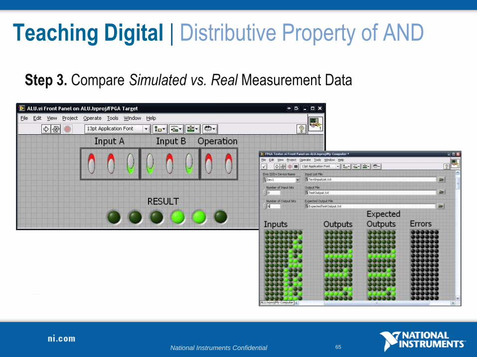
Step 3. Compare Simulated vs. Real Measurement Data
National Instruments Confidential 66
Programmable Logic Design
from Schematic
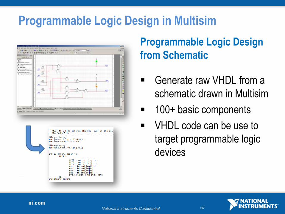
Generate raw VHDL from a
schematic drawn in Multisim
100+ basic components
VHDL code can be use to
target programmable logic
devices
Programmable Logic Design in Multisim
National Instruments Confidential 67
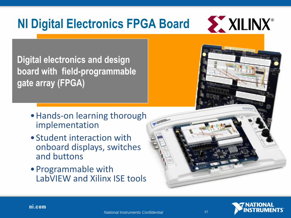
NI Digital Electronics FPGA Board
Digital electronics and design
board with field-programmable
gate array (FPGA)
•Hands-on learning thorough implementation
•Student interaction with onboard displays, switches and buttons
•Programmable with LabVIEW and Xilinx ISE tools

National Instruments Confidential 68
Teaching Digital Concepts
1. Capture a digital design
2. Use interactive simulation to reinforce
concepts
3. Use simulation driven instruments
4. Export design to VHDL
National Instruments Confidential 69
Exercise
Programmable Logic Schematic
Approximate time to complete: 20 minutes
Objective:
Use the PLD Schematic to explore the digital circuit.
Goa
l
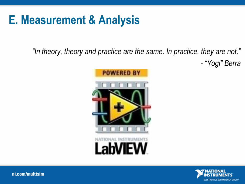
E. Measurement & Analysis
“In theory, theory and practice are the same. In practice, they are not.”
- “Yogi” Berra

71
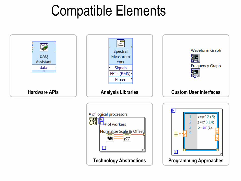
Hardware APIs
Deployment Targets
Custom User Interfaces
Programming ApproachesTechnology Abstractions
Elements of Engineering
Analysis Libraries
72
Programming Approaches
Analysis LibrariesHardware APIs Custom User Interfaces
Technology Abstractions
Compatible Elements
73
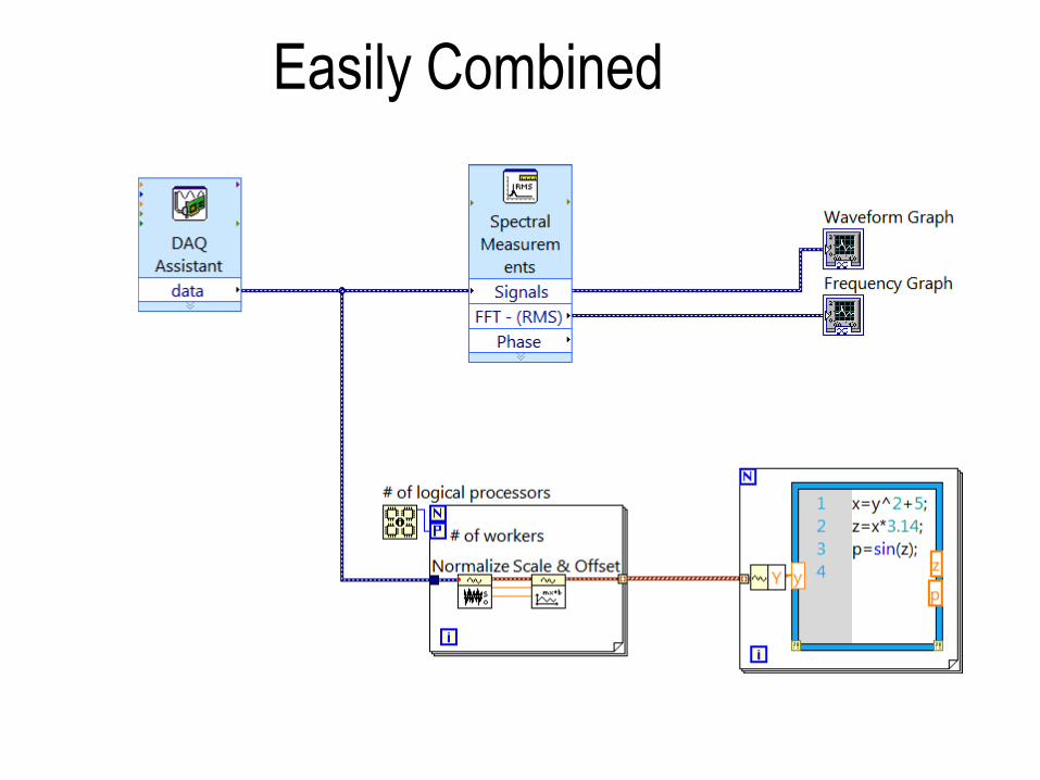
Easily Combined
74
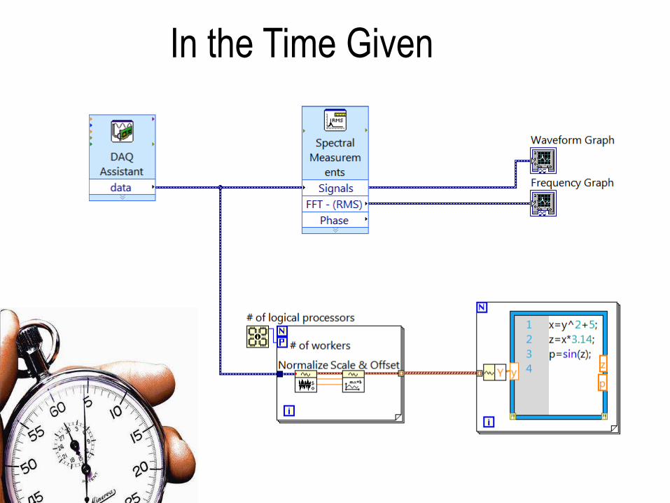
In the Time Given
75

76
LEGO ® MINDSTORMS® NXTpowered by LabVIEW
Collaboration with
Leading STEM Programs
Textbook & Author
Support Program
In More Than 7500
Universities in 110 Countries
LabVIEW Academy
Certification
Collaborative
Research
National Instruments Academic ProgramFrom Kindergarten to Rocket Science
77
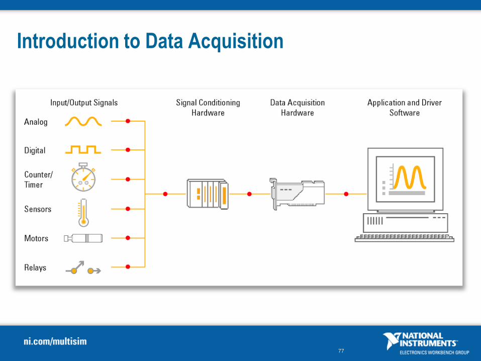
Introduction to Data Acquisition
78
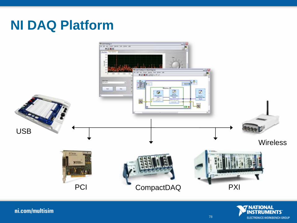
NI DAQ Platform
PCI PXI
USB
Wireless
CompactDAQ

79
DEMO
LabVIEW Environment
Objective:
Introduce the LabVIEW environment.Goa
l
80
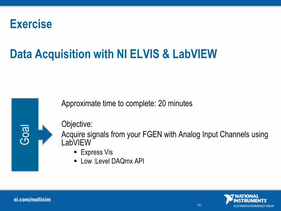
Exercise
Data Acquisition with NI ELVIS & LabVIEW
Approximate time to complete: 20 minutes
Objective:
Acquire signals from your FGEN with Analog Input Channels using LabVIEW
Express Vis
Low :Level DAQmx API
Goa
l

81
Exercise
Concept of While Loop
Approximate time to complete: 20 minutes
Objective:
Explore the concept of a while loop in LabVIEW using NI ELVIS as the hardware platform that will be acquiring signals.
Goa
l
82
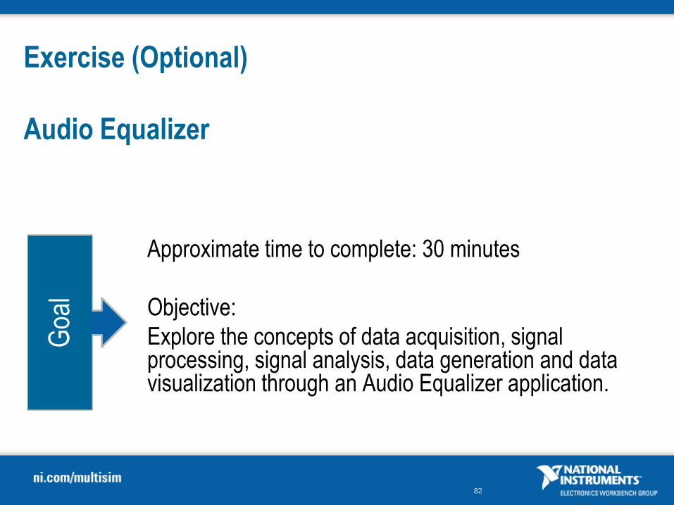
Exercise (Optional)
Audio Equalizer
Approximate time to complete: 30 minutes
Objective:
Explore the concepts of data acquisition, signal processing, signal analysis, data generation and data visualization through an Audio Equalizer application.
Goa
l
83
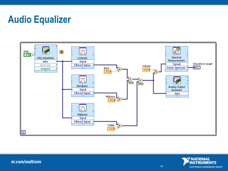
Audio Equalizer

99
Conclusion
Electronics Education Platform
National Instruments tools address challenges of circuit education
100
For more information
Contact Information:
• North America (800) 263-5552
• World-Wide Sales Offices Find Your Local Technical Expert
Product Support: ni.com/ask
Product information:
ni.com/multisim
ni.com/academic/eep
ni.com/academic/circuits
• Curricula: Practical Teaching Ideas, Teaching RF in Multisim, NI
ELVIS II
• Tutorials and whitepapers: How to tutorials and simulation
fundamentals