tdot - roadway design guidelines - tn.gov
TRANSCRIPT
TDOT - ROADWAY DESIGN GUIDELINES
English Revised: 09/30/2011
2-i
SECTION II - PRELIMINARY PLANS
CHAPTER 1 - DESIGN GUIDELINES
2-100.00 PROJECT FOLDER
2-105.00 ROADWAY DESIGN CHECKLIST - PRELIMINARY PLANS
2-110.00 PROJECT ACTIVITY STATUS SHEET
2-112.00 SIZE OF FULL-SIZE PLAN AND CROSS-SECTION SHEETS
2-115.00 IDENTIFICATION OF SUPERVISORS, DESIGNERS, AND CHECKERS ON TITLE SHEET
2-115.01 SPECIAL NOTES
2-115.05 EQUATION BLOCKS ON TITLE SHEET
2-115.10 EXCLUSIONS ON TITLE SHEET
2-115.15 TRAFFIC BLOCK ON TITLE SHEET
2-115.20 PROJECT DESCRIPTIONS
2-115.25 SPECIAL LOG MILE NOTE 2-120.00 TRAFFIC DATA FOR DESIGN
2-125.00 VERTICAL CLEARANCES FOR NON-INTERSTATE BRIDGES
2-127.00 SUBMITTAL OF PLANS FOR STRUCTURAL GRADE APPROVAL
2-130.00 SUPERELEVATION RATES AND RUN-OFF
2-135.00 THE CLEAR ZONE ROADSIDE CONCEPT
2-135.05 CLEAR ZONES ON CURVED ALIGNMENTS
2-140.00 MEDIAN OPENING SPACING
2-140.05 MEDIAN OPENING SPACING - EXAMPLE PROBLEMS
2-145.00 EXCAVATION AND UNDERCUTTING
2-145.05 EARTHWORK BALANCES
2-145.07 SUBMISSION OF GRADING QUANTITIES SHEETS
2-145.10 SHRINKAGE AND SWELL FACTORS
TDOT - ROADWAY DESIGN GUIDELINES
English Revised: 09/30/2011
2-ii
2-150.00 TRUCK CLIMBING LANES
2-150.01 LOCATION GUIDELINES
2-150.02 CAPACITY ANALYSIS
2-150.03 CRITICAL LENGTH OF GRADE
2-150.04 DESIGN GUIDELINES
2-150.05 DOWNGRADES
2-150.06 TRUCK SPEED PROFILE 2-155.00 WETLANDS BOUNDARY DESIGNATION
2-155.02 HAZARDOUS MATERIAL STUDY
2-155.05 BOX AND SLAB-TYPE CULVERT AND BRIDGE LENGTHS, CHANNEL CHANGES, AND WETLANDS
2-160.00 EXTENSION OF THROUGH LANES BEYOND INTERSECTIONS AND REQUIREMENTS FOR LANE REDUCTION TRANSITION LENGTHS
2-165.00 TWO-LANE ENTRANCE RAMPS ON FREEWAYS AND EXPRESSWAYS
2-170.00 GUIDELINES FOR DESIGN OF TURNING LANES
2-175.00 GUIDELINES FOR DETERMINING AND PROPOSING RETAINING WALLS
2-180.00 LOCATION OF AUTOMATIC TRAFFIC RECORDERS (ATR) AND ROADWAY WEATHER INFORMATION SYSTEMS (RWIS) ON PROJECTS
CHAPTER 2 – DRAINAGE
2-200.00 DRAINAGE MANUAL
2-200.01 COMPUTATION OF DRAINAGE
2-200.05 DRAINAGE TABLES AND CHARTS
2-200.10 EXAMPLE DRAINAGE PROBLEMS
TDOT - ROADWAY DESIGN GUIDELINES
English Revised: 09/30/2011
2-iii
CHAPTER 3 - RIGHT -OF-WAY
2-300.00 R.O.W. NOTES FOR ALL R.O.W. PROJECTS
2-300.05 R.O.W. NOTES ON PLANS REGARDING DRIVEWAYS
2-300.10 GUIDELINES FOR CONSTRUCTION AND RESURFACING OF PUBLIC ROAD INTERSECTIONS AND DRIVEWAYS ON HIGHWAY PROJECTS
2-310.00 ACCESS CONTROL - CROSSROADS AT INTERCHANGES
2-315.00 TRAFFIC SIGNAL AND LIGHTING DESIGNS FOR ROADWAY PROJECTS
2-315.05 ROADWAY LIGHTING INFORMATION FOR RIGHT-OF-WAY/UTILITIES
2-320.00 EASEMENTS - GENERAL
2-320.05 PERMANENT DRAINAGE EASEMENT ON PLANS
2-320.10 SLOPE EASEMENTS
2-320.15 CONSTRUCTION EASEMENTS
2-320.20 PRELIMINARY RIGHT-OF-WAY ESTIMATE FROM PRELIMINARY FIELD REVIEW PLANS
2-325.00 RAILROADS
2-330.00 FIELD REVIEW PROCEDURES

TDOT - ROADWAY DESIGN GUIDELINES English Revised: 09/30/2011
2-1
TDOT - ROADWAY DESIGN GUIDELINES English Revised: 09/30/2011
2-2
SECTION II - PRELIMINARY PLANS
CHAPTER 1 - DESIGN GUIDELINES 2-100.00 PROJECT FOLDER (See 1-100.00) 2-105.00 ROADWAY DESIGN CHECKLIST - PRELIMINARY PLANS (See 1-105.00) 2-110.00 PROJECT ACTIVITY STATUS SHEET (See 1-110.00) 2-112.00 SIZE OF FULL-SIZE PLAN AND CROSS-SECTION SHEETS (See 3-102.00
and 4-112.00) All full size plans submitted for printing shall be 34” x 22”. No size variation will be allowed. 2-115.00 IDENTIFICATION OF SUPERVISORS, DESIGNERS, AND CHECKERS ON
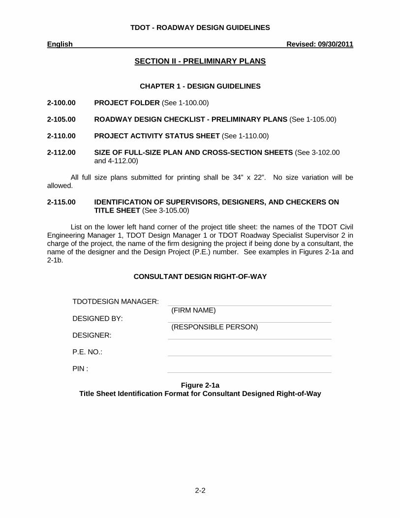
TITLE SHEET (See 3-105.00) List on the lower left hand corner of the project title sheet: the names of the TDOT Civil Engineering Manager 1, TDOT Design Manager 1 or TDOT Roadway Specialist Supervisor 2 in charge of the project, the name of the firm designing the project if being done by a consultant, the name of the designer and the Design Project (P.E.) number. See examples in Figures 2-1a and 2-1b. CONSULTANT DESIGN RIGHT-OF-WAY
TDOTDESIGN MANAGER: DESIGNED BY:
(FIRM NAME)
DESIGNER:
(RESPONSIBLE PERSON)
P.E. NO.:
PIN :
Figure 2-1a
Title Sheet Identification Format for Consultant Designed Right-of-Way
TDOT - ROADWAY DESIGN GUIDELINES English Revised: 09/30/2011
2-3
T.D.O.T. DESIGN RIGHT-OF-WAY TDOT ROAD SP. SV. 2:
DESIGNER:
P.E. NO.:
PIN :
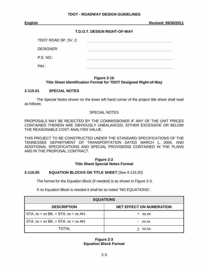
Figure 2-1b Title Sheet Identification Format for TDOT Designed Right-of-Way
2-115.01 SPECIAL NOTES The Special Notes shown on the lower left hand corner of the project title sheet shall read as follows:
SPECIAL NOTES PROPOSALS MAY BE REJECTED BY THE COMMISSIONER IF ANY OF THE UNIT PRICES CONTAINED THEREIN ARE OBVIOUSLY UNBALANCED, EITHER EXCESSIVE OR BELOW THE REASONABLE COST ANALYSIS VALUE. THIS PROJECT TO BE CONSTRUCTED UNDER THE STANDARD SPECIFICATIONS OF THE TENNESSEE DEPARTMENT OF TRANSPORTATION DATED MARCH 1, 2006, AND ADDITIONAL SPECIFICATIONS AND SPECIAL PROVISIONS CONTAINED IN THE PLANS AND IN THE PROPOSAL CONTRACT.
Figure 2-2
Title Sheet Special Notes Format 2-115.05 EQUATION BLOCKS ON TITLE SHEET (See 4-115.20) The format for the Equation Block (if needed) is as shown in Figure 2-3. If no Equation Block is needed it shall be so noted "NO EQUATIONS".
EQUATIONS
DESCRIPTION NET EFFECT ON NUMERATION
STA. xx + xx BK. = STA. xx + xx AH. + xx.xx
STA. xx + xx BK. = STA. xx + xx AH. - xx.xx
TOTAL + xx.xx
Figure 2-3
Equation Block Format
TDOT - ROADWAY DESIGN GUIDELINES English Revised: 09/30/2011
2-4
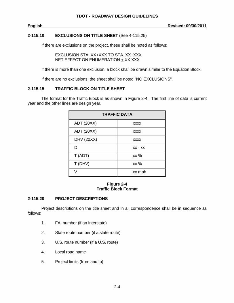
2-115.10 EXCLUSIONS ON TITLE SHEET (See 4-115.25) If there are exclusions on the project, these shall be noted as follows: EXCLUSION STA. XX+XXX TO STA. XX+XXX NET EFFECT ON ENUMERATION + XX.XXX If there is more than one exclusion, a block shall be drawn similar to the Equation Block. If there are no exclusions, the sheet shall be noted "NO EXCLUSIONS". 2-115.15 TRAFFIC BLOCK ON TITLE SHEET The format for the Traffic Block is as shown in Figure 2-4. The first line of data is current year and the other lines are design year.
TRAFFIC DATA
ADT (20XX) xxxx
ADT (20XX) xxxx
DHV (20XX) xxxx
D xx - xx
T (ADT) xx %
T (DHV) xx %
V xx mph
Figure 2-4
Traffic Block Format 2-115.20 PROJECT DESCRIPTIONS Project descriptions on the title sheet and in all correspondence shall be in sequence as follows: 1. FAI number (if an Interstate) 2. State route number (if a state route) 3. U.S. route number (if a U.S. route) 4. Local road name 5. Project limits (from and to)
TDOT - ROADWAY DESIGN GUIDELINES English Revised: 09/30/2011
2-5
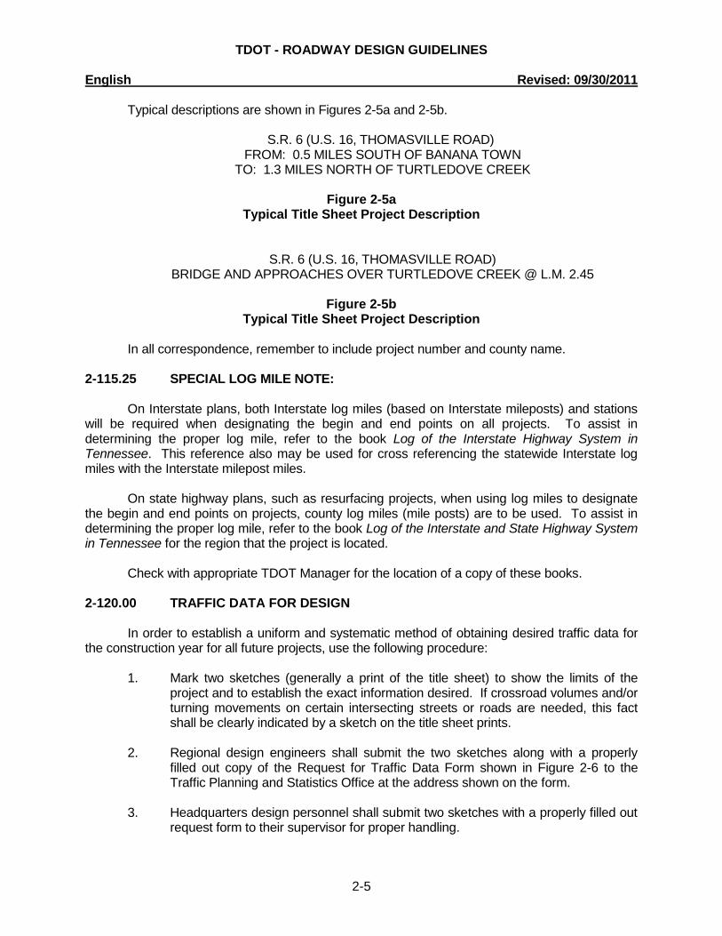
Typical descriptions are shown in Figures 2-5a and 2-5b.
S.R. 6 (U.S. 16, THOMASVILLE ROAD) FROM: 0.5 MILES SOUTH OF BANANA TOWN
TO: 1.3 MILES NORTH OF TURTLEDOVE CREEK
Figure 2-5a Typical Title Sheet Project Description
S.R. 6 (U.S. 16, THOMASVILLE ROAD) BRIDGE AND APPROACHES OVER TURTLEDOVE CREEK @ L.M. 2.45
Figure 2-5b
Typical Title Sheet Project Description
In all correspondence, remember to include project number and county name. 2-115.25 SPECIAL LOG MILE NOTE: On Interstate plans, both Interstate log miles (based on Interstate mileposts) and stations will be required when designating the begin and end points on all projects. To assist in determining the proper log mile, refer to the book Log of the Interstate Highway System in Tennessee. This reference also may be used for cross referencing the statewide Interstate log miles with the Interstate milepost miles. On state highway plans, such as resurfacing projects, when using log miles to designate the begin and end points on projects, county log miles (mile posts) are to be used. To assist in determining the proper log mile, refer to the book Log of the Interstate and State Highway System in Tennessee for the region that the project is located. Check with appropriate TDOT Manager for the location of a copy of these books. 2-120.00 TRAFFIC DATA FOR DESIGN In order to establish a uniform and systematic method of obtaining desired traffic data for the construction year for all future projects, use the following procedure:
1. Mark two sketches (generally a print of the title sheet) to show the limits of the project and to establish the exact information desired. If crossroad volumes and/or turning movements on certain intersecting streets or roads are needed, this fact shall be clearly indicated by a sketch on the title sheet prints.
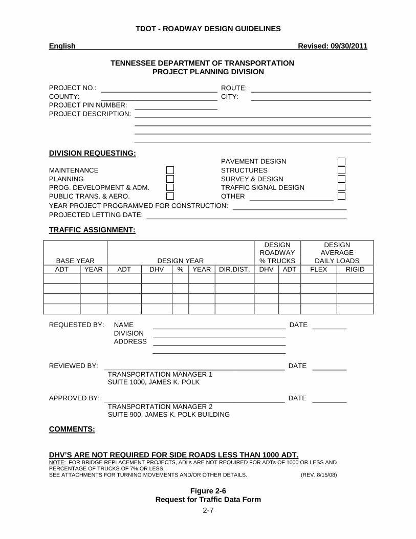
2. Regional design engineers shall submit the two sketches along with a properly
filled out copy of the Request for Traffic Data Form shown in Figure 2-6 to the Traffic Planning and Statistics Office at the address shown on the form.
3. Headquarters design personnel shall submit two sketches with a properly filled out
request form to their supervisor for proper handling.
TDOT - ROADWAY DESIGN GUIDELINES English Revised: 09/30/2011
2-6
4. Consultants shall submit two sketches with a properly filled out form to the appropriate Design Manager.
Since the typical cross-section to be used is largely dependent on the anticipated traffic, it is urgent that traffic data for each newly assigned project be requested as soon as possible after beginning work on a project. To expedite a pavement design from the Pavement Design Section, the following applicable notes shall be included under comments on the form. A copy of the completed form shall be forwarded with the pavement design request.
1. Furnish the 20xx-20xx ADL for pavement design on a four-lane roadway. 2. Furnish the 20xx-20xx ADL for pavement design on a four-lane roadway and the
present ADT on all crossroads within the limits of the project. 3. Furnish the 20xx-20xx ADL for pavement design on a two-lane roadway. 4. Furnish the 20xx-20xx ADL for pavement design on a two-lane roadway and the
present ADT on all crossroads within the limits of the project. NOTE: ADL (Average Daily Loading) ADT (Average Daily Traffic) DHV (Design Hourly Volume) D (Directional Distribution) T (Truck Percentage) NOTE: For Bridge Replacement Projects, ADL are not required for ADTs of 1,000 or less and percentage trucks of 7 percent or less. NOTE: ADTs and DHVs are not required for crossroads with ADTs of 1,000 or less.
TDOT - ROADWAY DESIGN GUIDELINES English Revised: 09/30/2011
2-7
TENNESSEE DEPARTMENT OF TRANSPORTATION PROJECT PLANNING DIVISION
PROJECT NO.:
ROUTE:
COUNTY: CITY: PROJECT PIN NUMBER: PROJECT DESCRIPTION: DIVISION REQUESTING:
PAVEMENT DESIGN MAINTENANCE STRUCTURES PLANNING SURVEY & DESIGN PROG. DEVELOPMENT & ADM. TRAFFIC SIGNAL DESIGN PUBLIC TRANS. & AERO. OTHER YEAR PROJECT PROGRAMMED FOR CONSTRUCTION: PROJECTED LETTING DATE: TRAFFIC ASSIGNMENT:
DESIGN DESIGN ROADWAY AVERAGE BASE YEAR DESIGN YEAR % TRUCKS DAILY LOADS
ADT YEAR ADT DHV % YEAR
DIR.DIST. DHV ADT FLEX RIGID
REQUESTED BY: NAME DATE DIVISION ADDRESS REVIEWED BY: DATE
TRANSPORTATION MANAGER 1 SUITE 1000, JAMES K. POLK
APPROVED BY: DATE
TRANSPORTATION MANAGER 2 SUITE 900, JAMES K. POLK BUILDING
COMMENTS:
DHV’S ARE NOT REQUIRED FOR SIDE ROADS LESS THAN 1000 ADT. NOTE: FOR BRIDGE REPLACEMENT PROJECTS, ADLs ARE NOT REQUIRED FOR ADTs OF 1000 OR LESS AND PERCENTAGE OF TRUCKS OF 7% OR LESS. SEE ATTACHMENTS FOR TURNING MOVEMENTS AND/OR OTHER DETAILS. (REV. 8/15/08)
Figure 2-6
Request for Traffic Data Form
TDOT - ROADWAY DESIGN GUIDELINES English Revised: 09/30/2011
2-8
2-125.00 VERTICAL CLEARANCES FOR NON-INTERSTATE BRIDGES The minimum vertical clearance for all structures on all systems shall be not less than 16 feet over the entire roadway width, including the usable width of shoulder. The vertical clearance to sign trusses and pedestrian overpasses shall be 17 feet because of their lesser resistance to impacts. The vertical clearance from the deck to the cross bracing on through truss structures shall also be a minimum of 17 feet. The vertical clearance for railroad crossings from structure to top of rails shall be 23 feet. An allowance of 6 inches shall be added to all vertical clearances to accommodate future resurfacing. On crossings of low volume roadways where the cost of providing a 16 feet clearance might be considered unreasonable and may justify an exception, the Design and Structures Division personnel shall complete a joint cost analysis justifying a reduction in vertical clearance. This cost analysis shall be submitted to the Director of the Structures Division for approval. 2-127.00 SUBMITTAL OF PLANS FOR STRUCTURAL GRADE APPROVAL The designer in the Structures Division shall receive all the material applicable to the drainage portion of the project as specified in Section 2.50 of the Survey Manual when receiving the survey. In addition, they shall receive all the material applicable to grade separations at highway and railroad crossings as specified in Section 2.70 of the Survey Manual when receiving the survey. When grade approval is requested the following material shall be placed on File Net for use by the Structures Division. 1. Floodplain sections (stream crossing) 2. Stream profiles (stream crossing) 3. Roadway and railroad profile (see Section 1-210.00) 4. Topography A. See Section 2.50 and 2.70, and the Survey Check List, Box Bridge and Bridge Surveys Section of the latest edition of the Survey Manual B. Low girder and bridge deck elevations C. Stations for each substructure 5. Complete set of full-size preliminary plans with prints of digital terrain model sheets at bridge locations An email notification requesting structural grade approval should be sent to the Structures Division once the required materials are placed on File Net. If a grade or alignment change is made on the project subsequent to the submission for grade approval, all revised information should be resubmitted to the Structures Division if the Design Manager determines it affects a structure. A copy of the e-mail shall be placed in the project folder to document the submittal of structural grade approval request.
TDOT - ROADWAY DESIGN GUIDELINES English Revised: 09/30/2011
2-9
2-130.00 SUPERELEVATION RATES AND RUN-OFF On all major grade and drain projects spirals will be required on horizontal curves below the heavy lines as shown on Standard Drawings RD01-SE series. For horizontal curves above the heavy lines spirals may still be used. On isolated bridge replacement projects, intersection improvements, widening of existing roadways, etc., where use of spirals would provide no real benefit and/or cause problems in design, spirals will not be required. It will still be necessary to provide superelevation and superelevation lengths as shown on RD01-SE series. On urban projects, note that the maximum desirable superelevation rate is 4 percent. On rural projects, the maximum desirable superelevation rate is 8 percent. On "BRZ" projects with design speed of 30 mph or less and with gravel or "spot" double bituminous surface treatment, a maximum superelevation rate of 6 percent may be used without a design exception being required. Exceptions to this policy shall be identified in field review reports. Show the superelevation rate and speed on all plans as a part of the horizontal curve data, thus: "S.E. 5.4% 70 mph". Also, show transition length on non-spiraled curves. 2-135.00 THE CLEAR ZONE ROADSIDE CONCEPT Clear zone distance (sometime referred to as clear zone, horizontal clearance to obstructions or roadside recovery area) as defined in the AASHTO Roadside Design Guide, other parts of this document and in other official publications shall be maintained on all projects. 2-135.05 CLEAR ZONES ON CURVED ALIGNMENTS In Chapter 3 of the AASHTO Roadside Design Guide a formula is given for increase in clear zone on the outside of curves. The clear zone on curved alignment is determined by increasing the value obtained from the Roadside Design Guide method for a tangent section of highway. The tangent section clear zone is increased by a curve correction factor, which is based on the degree of curvature and the design speed. One note of caution, the designer must remember that the clear zone values (Lc) obtained are based on a constant side slope throughout the clear zone distance. In situations where the side slope changes within the calculated clear zone, the clear zone must be recalculated based on a weighted average of the side slopes.
TDOT - ROADWAY DESIGN GUIDELINES English Revised: 09/30/2011
2-10
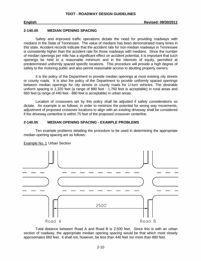
2-140.00 MEDIAN OPENING SPACING Safety and improved traffic operations dictate the need for providing roadways with medians in the State of Tennessee. The value of medians has been demonstrated many times in this state. Accident records indicate that the accident rate for non-median roadways in Tennessee is consistently higher than the accident rate for those roadways with medians. Since the number of median openings per mile has a significant effect on accident potential, it is important that such openings be held to a reasonable minimum and in the interests of equity, permitted at predetermined uniformly spaced specific locations. This procedure will provide a high degree of safety to the motoring public and also permit reasonable access to abutting property owners. It is the policy of the Department to provide median openings at most existing city streets or county roads. It is also the policy of the Department to provide uniformly spaced openings between median openings for city streets or county roads for U-turn vehicles. The desirable uniform spacing is 1,320 feet (a range of 880 feet - 1,760 feet is acceptable) in rural areas and 660 feet (a range of 440 feet - 880 feet is acceptable) in urban areas. Location of crossovers set by this policy shall be adjusted if safety considerations so dictate. An example is as follows: in order to minimize the potential for wrong way movements, adjustment of proposed crossover locations to align with an existing driveway shall be considered if the driveway centerline is within 75 feet of the proposed crossover centerline. 2-140.05 MEDIAN OPENING SPACING - EXAMPLE PROBLEMS Ten example problems detailing the procedure to be used in determining the appropriate median opening spacing are as follows: Example No. 1 Urban Section
Total distance between Road A and Road B is 2,500 feet. Since this is with an urban section of roadway, the appropriate median opening spacing would be that which most closely approximates 660 feet. It shall not, however, be less than 440 feet nor more than 880 feet.
TDOT - ROADWAY DESIGN GUIDELINES English Revised: 09/30/2011
2-11
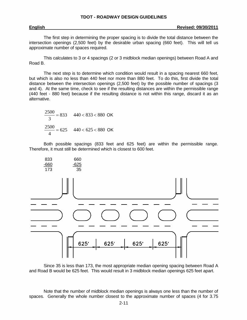
The first step in determining the proper spacing is to divide the total distance between the intersection openings (2,500 feet) by the desirable urban spacing (660 feet). This will tell us approximate number of spaces required.
This calculates to 3 or 4 spacings (2 or 3 midblock median openings) between Road A and
Road B. The next step is to determine which condition would result in a spacing nearest 660 feet, but which is also no less than 440 feet nor more than 880 feet. To do this, first divide the total distance between the intersection openings (2,500 feet) by the possible number of spacings (3 and 4). At the same time, check to see if the resulting distances are within the permissible range (440 feet - 880 feet) because if the resulting distance is not within this range, discard it as an alternative.
8333
2500= 880833440 << OK
6254
2500= 880625440 << OK
Both possible spacings (833 feet and 625 feet) are within the permissible range. Therefore, it must still be determined which is closest to 600 feet. 833 660 -660 -625 173 35
Since 35 is less than 173, the most appropriate median opening spacing between Road A
and Road B would be 625 feet. This would result in 3 midblock median openings 625 feet apart.
Note that the number of midblock median openings is always one less than the number of spaces. Generally the whole number closest to the approximate number of spaces (4 for 3.75
TDOT - ROADWAY DESIGN GUIDELINES English Revised: 09/30/2011
2-12
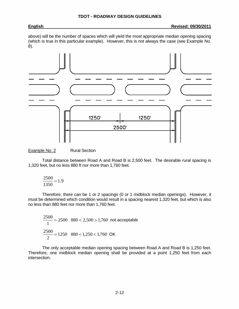
above) will be the number of spaces which will yield the most appropriate median opening spacing (which is true in this particular example). However, this is not always the case (see Example No. 8).
Example No. 2 Rural Section Total distance between Road A and Road B is 2,500 feet. The desirable rural spacing is 1,320 feet, but no less 880 ft nor more than 1,760 feet.
9.113502500
=
Therefore, there can be 1 or 2 spacings (0 or 1 midblock median openings). However, it must be determined which condition would result in a spacing nearest 1,320 feet, but which is also no less than 880 feet nor more than 1,760 feet.
25001
2500= 760,1500,2880 >< not acceptable
12502
2500= 760,1250,1880 << OK
The only acceptable median opening spacing between Road A and Road B is 1,250 feet. Therefore, one midblock median opening shall be provided at a point 1,250 feet from each intersection.
TDOT - ROADWAY DESIGN GUIDELINES English Revised: 09/30/2011
2-13
Example No. 3 Urban Section Total distance between intersection openings is 1,100 feet.
7.1660
1100=
11001
1100= 880100,1440 >< not acceptable
5502
1100= 880550440 << OK
The only acceptable spacing is 550 feet. Therefore, one midblock median opening shall
be provided at a point 550 feet from each intersection. Example No. 4 Rural Section Total distance between intersection openings is 1,100 feet.
8.013201100
=
=0
1100 infinity infinity 100,1< not acceptable
11001
1100= 760,1100,1880 << OK
The only acceptable spacing is 1,100 feet and, therefore, no midblock median opening shall be installed. Example No. 5 Urban Section Total distance between intersection openings is 1,500 feet.
3.2660
1500=
7502
1500= 880750440 << OK
5003
1500= 880500440 << OK

TDOT - ROADWAY DESIGN GUIDELINES English Revised: 09/30/2011
2-14
660 750 -500 -660 160 90 Since 90 feet is less than 160 feet, the most appropriate median opening spacing would be 750 feet. Therefore, 1 midblock median opening shall be installed. Example No. 6 Rural Section Total distance = 1,500 feet
1.113201500
=
15001
1500= 760,1500,1880 << OK
7502
1500= 880750 < not acceptable
The only acceptable spacing is 1,500 feet. Therefore, no midblock opening shall be installed. Example No. 7 Urban Section Total distance = 5,880 feet
9.8660
5880=
7358
5880= 880735440 << OK
6539
5880= 880653440 << OK
735 660 -660 -653 75 7 Since 7 is less than 75, the appropriate spacing is 653 feet resulting in 8 midblock median openings.
TDOT - ROADWAY DESIGN GUIDELINES English Revised: 09/30/2011
2-15
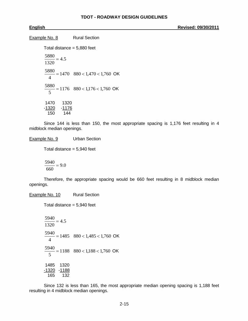
Example No. 8 Rural Section Total distance = 5,880 feet
5.413205880
=
14704
5880= 760,1470,1880 << OK
11765
5880= 760,1176,1880 << OK
1470 1320 -1320 -1176 150 144 Since 144 is less than 150, the most appropriate spacing is 1,176 feet resulting in 4 midblock median openings. Example No. 9 Urban Section Total distance = 5,940 feet
0.9660
5940=
Therefore, the appropriate spacing would be 660 feet resulting in 8 midblock median openings. Example No. 10 Rural Section Total distance = 5,940 feet
5.413205940
=
14854
5940= 760,1485,1880 << OK
11885
5940= 760,1188,1880 << OK
1485 1320 -1320 -1188 165 132 Since 132 is less than 165, the most appropriate median opening spacing is 1,188 feet resulting in 4 midblock median openings.
TDOT - ROADWAY DESIGN GUIDELINES English Revised: 09/30/2011
2-16
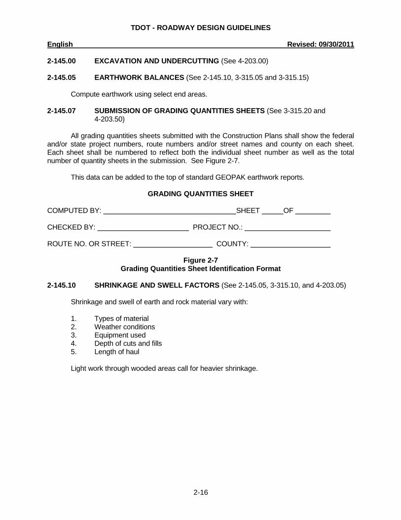
2-145.00 EXCAVATION AND UNDERCUTTING (See 4-203.00) 2-145.05 EARTHWORK BALANCES (See 2-145.10, 3-315.05 and 3-315.15) Compute earthwork using select end areas. 2-145.07 SUBMISSION OF GRADING QUANTITIES SHEETS (See 3-315.20 and
4-203.50) All grading quantities sheets submitted with the Construction Plans shall show the federal and/or state project numbers, route numbers and/or street names and county on each sheet. Each sheet shall be numbered to reflect both the individual sheet number as well as the total number of quantity sheets in the submission. See Figure 2-7. This data can be added to the top of standard GEOPAK earthwork reports.
GRADING QUANTITIES SHEET COMPUTED BY: SHEET OF CHECKED BY: PROJECT NO.: ROUTE NO. OR STREET: COUNTY:
Figure 2-7 Grading Quantities Sheet Identification Format
2-145.10 SHRINKAGE AND SWELL FACTORS (See 2-145.05, 3-315.10, and 4-203.05) Shrinkage and swell of earth and rock material vary with: 1. Types of material 2. Weather conditions 3. Equipment used 4. Depth of cuts and fills 5. Length of haul Light work through wooded areas call for heavier shrinkage.
TDOT - ROADWAY DESIGN GUIDELINES English Revised: 09/30/2011
2-17
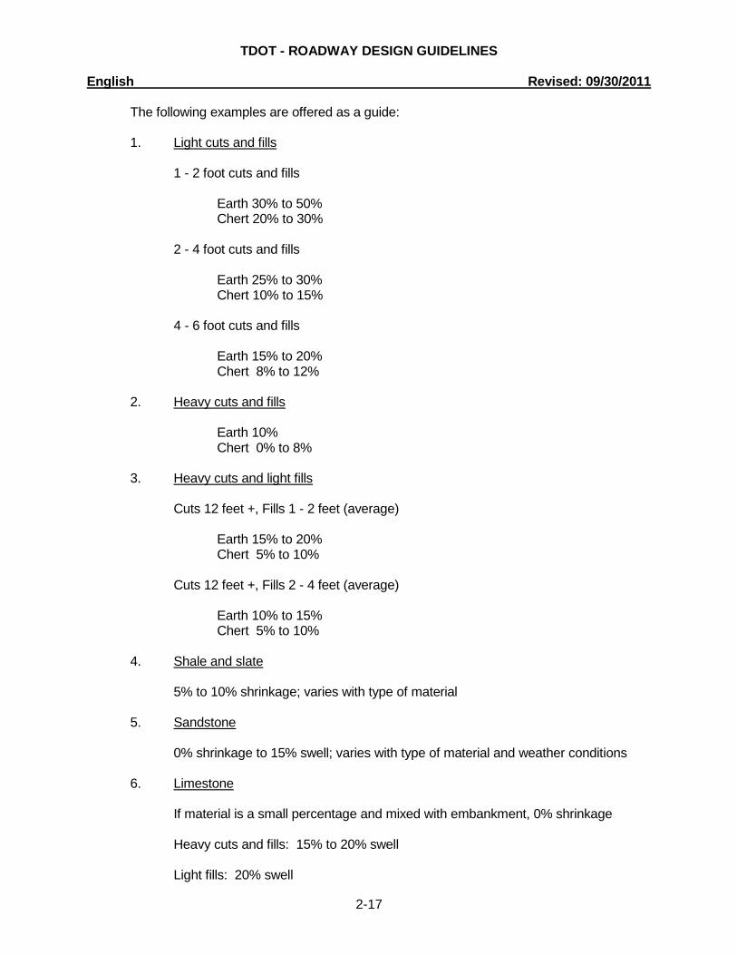
The following examples are offered as a guide: 1. Light cuts and fills 1 - 2 foot cuts and fills Earth 30% to 50% Chert 20% to 30%
2 - 4 foot cuts and fills Earth 25% to 30% Chert 10% to 15% 4 - 6 foot cuts and fills
Earth 15% to 20% Chert 8% to 12% 2. Heavy cuts and fills Earth 10% Chert 0% to 8% 3. Heavy cuts and light fills Cuts 12 feet +, Fills 1 - 2 feet (average) Earth 15% to 20% Chert 5% to 10% Cuts 12 feet +, Fills 2 - 4 feet (average) Earth 10% to 15% Chert 5% to 10%
4. Shale and slate 5% to 10% shrinkage; varies with type of material 5. Sandstone 0% shrinkage to 15% swell; varies with type of material and weather conditions 6. Limestone If material is a small percentage and mixed with embankment, 0% shrinkage Heavy cuts and fills: 15% to 20% swell Light fills: 20% swell
TDOT - ROADWAY DESIGN GUIDELINES English Revised: 09/30/2011
2-18
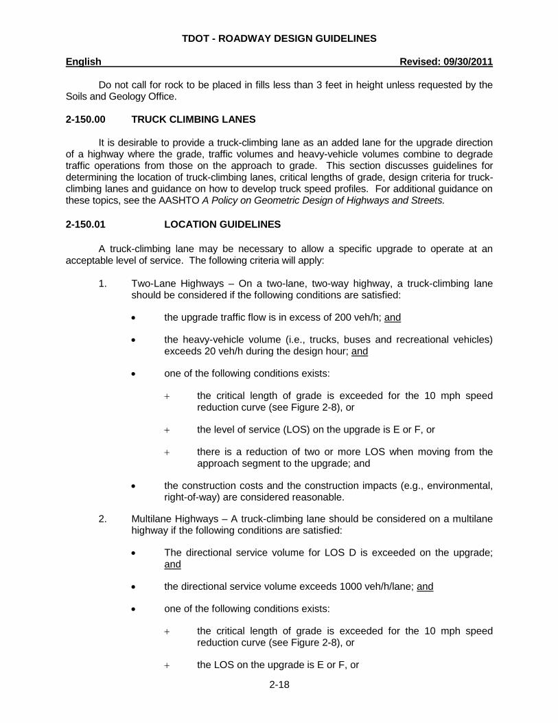
Do not call for rock to be placed in fills less than 3 feet in height unless requested by the Soils and Geology Office. 2-150.00 TRUCK CLIMBING LANES
It is desirable to provide a truck-climbing lane as an added lane for the upgrade direction of a highway where the grade, traffic volumes and heavy-vehicle volumes combine to degrade traffic operations from those on the approach to grade. This section discusses guidelines for determining the location of truck-climbing lanes, critical lengths of grade, design criteria for truck-climbing lanes and guidance on how to develop truck speed profiles. For additional guidance on these topics, see the AASHTO A Policy on Geometric Design of Highways and Streets. 2-150.01 LOCATION GUIDELINES
A truck-climbing lane may be necessary to allow a specific upgrade to operate at an acceptable level of service. The following criteria will apply:
1. Two-Lane Highways – On a two-lane, two-way highway, a truck-climbing lane
should be considered if the following conditions are satisfied:
• the upgrade traffic flow is in excess of 200 veh/h; and
• the heavy-vehicle volume (i.e., trucks, buses and recreational vehicles) exceeds 20 veh/h during the design hour; and
• one of the following conditions exists:
+ the critical length of grade is exceeded for the 10 mph speed reduction curve (see Figure 2-8), or
+ the level of service (LOS) on the upgrade is E or F, or
+ there is a reduction of two or more LOS when moving from the approach segment to the upgrade; and
• the construction costs and the construction impacts (e.g., environmental, right-of-way) are considered reasonable.
2. Multilane Highways – A truck-climbing lane should be considered on a multilane highway if the following conditions are satisfied:
• The directional service volume for LOS D is exceeded on the upgrade; and
• the directional service volume exceeds 1000 veh/h/lane; and
• one of the following conditions exists:
+ the critical length of grade is exceeded for the 10 mph speed reduction curve (see Figure 2-8), or
+ the LOS on the upgrade is E or F, or

TDOT - ROADWAY DESIGN GUIDELINES English Revised: 09/30/2011
2-19
+ there is a reduction of one or more LOS when moving from the approach segment to the upgrade; and
• the construction costs and the construction impacts (e.g., environmental, right-of-way) are considered reasonable.
Also, truck-climbing lanes should be considered where the above criteria are not met and if there is an adverse crash experience on the upgrade related to slow-moving heavy vehicles. 2-150.02 CAPACITY ANALYSIS
See the Highway Capacity Manual 2010 for guidance on conducting capacity analyses for climbing lanes on two-lane and multilane highways. 2-150.03 CRITICAL LENGTH OF GRADE
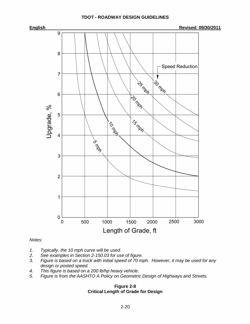
The critical length of grade is the maximum length of a specific upgrade on which a truck can operate without an unreasonable reduction in speed. The highway gradient, in combination with the length of the grade will determine the truck speed reduction on upgrades.
The following will apply to the critical length of grade: 1. Design Vehicle – Figure 2-8 presents the critical length of grade for a 200 lb/hp
truck. This vehicle is representative of size and type of a heavy vehicle normally used for design on main roads.
2. Criteria – Figure 2-8 provides the critical lengths of grade for a given percent
grade and acceptable truck speed reduction. Although these curves are based on an initial truck speed of 70 mph, they apply to any design or posted speed. For design purposes, use the 10 mph speed reduction curve in the figure to determine if the critical length of grade is exceeded.
3. Momentum Grades – Where an upgrade is preceded by a downgrade, trucks will often increase their speed to ascend the upgrade. A speed increase of 5 mph on moderate downgrades (3%-5%) and 10 mph on steeper downgrades (6%-8%) of sufficient length are reasonable adjustments to the initial speed. This assumption allows the use of a higher speed reduction curve in Figure 2-8. However, the designer should also consider that these speed increases may not always be attainable. If traffic volumes are sufficiently high, a truck may be behind another vehicle when descending the momentum grade, thereby restricting the increase in speed. Therefore, only consider these increases in speed if the highway has a Level of Service C or better.
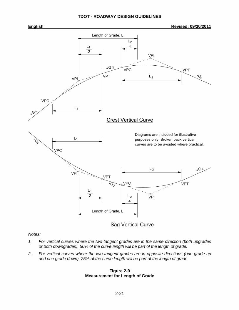
4. Measurement – Vertical curves are part of the length of grade. Figure 2-9 illustrates how to measure the length of grade to determine the critical length of grade using Figure 2-8.
5. Application – If the critical length of grade is exceeded, flatten the grade, if practical, or evaluate the need for a truck-climbing lane. Typically, only two-lane highways have operational problems that require truck-climbing lanes.
TDOT - ROADWAY DESIGN GUIDELINES English Revised: 09/30/2011
2-20
Notes: 1. Typically, the 10 mph curve will be used. 2. See examples in Section 2-150.03 for use of figure. 3. Figure is based on a truck with initial speed of 70 mph. However, it may be used for any
design or posted speed. 4. This figure is based on a 200 lb/hp heavy vehicle. 5. Figure is from the AASHTO A Policy on Geometric Design of Highways and Streets.
Figure 2-8 Critical Length of Grade for Design
TDOT - ROADWAY DESIGN GUIDELINES English Revised: 09/30/2011
2-21
Notes:
1. For vertical curves where the two tangent grades are in the same direction (both upgrades or both downgrades), 50% of the curve length will be part of the length of grade.
2. For vertical curves where the two tangent grades are in opposite directions (one grade up and one grade down), 25% of the curve length will be part of the length of grade.
Figure 2-9
Measurement for Length of Grade
TDOT - ROADWAY DESIGN GUIDELINES English Revised: 09/30/2011
2-22
6. Highway Types – The critical-length-of-grade criteria applies equally to two-lane or multilane highways, and applies equally to urban and rural facilities
7. Alternative Critical Lengths of Grades – In many design situations, Figure 2-8
may not be directly applicable to the determination of the critical length of grade for one of following reasons:
• The truck population for a given site may be such that a weight/power ratio is either less than or greater than the 200 lb/hp design vehicle (e.g., coal mining trucks, gravel trucks).
• The truck speed at the entrance to the grade may differ from the 70 mph assumed in Figure 2-8.
• The profile may not consist of a constant percent grade.
For these situations, the designer may want to consider using the software program Truck Speed Profile Model (TSPM) described in NCHRP Report 505 Review of Truck Characteristics as Factors in Roadway Design to determine the applicable critical length of grade. This program may be used to generate speed truck profiles for any specified truck weight/power ratio, initial truck speed and sequence of grades.
8. Example Problems – Examples No. 1 and No. 2 illustrate the use of Figure 2-8 to determine the critical length of grade. Example No. 3 illustrates the use of Figures 2-8 and 2-9. In the examples, the use of subscripts 1, 2, etc., indicate the successive gradients and lengths of grade on the highway segment.
Example No. 1 Given: Level Approach G = +4% L = 1500 ft (length of grade) Rural Principal Arterial Problem: Determine if the critical length of grade is exceeded. Solution: Figure 2-8 yields a critical length of grade of 1200 ft for a 10-mph speed reduction.
The length of grade (L) exceeds this value. Therefore, flatten the grade, if practical, or evaluate the need for a truck-climbing lane.
Example No. 2 Given: Level Approach G1 = +4.5% L1 = 500 ft G2 = +2% L2 = 700 ft Rural Arterial with a significant number of heavy trucks Problem: Determine if the critical length of grade is exceeded for the combination of grades G1
and G2.
TDOT - ROADWAY DESIGN GUIDELINES English Revised: 09/30/2011
2-23
Solution: From Figure 2-8, G1 yields a truck speed reduction of 5 mph. G2 yields a speed
reduction of approximately 3 mph. The total of 8 mph is less than the maximum 10 mph speed reduction. Therefore, the critical length of grade is not exceeded.
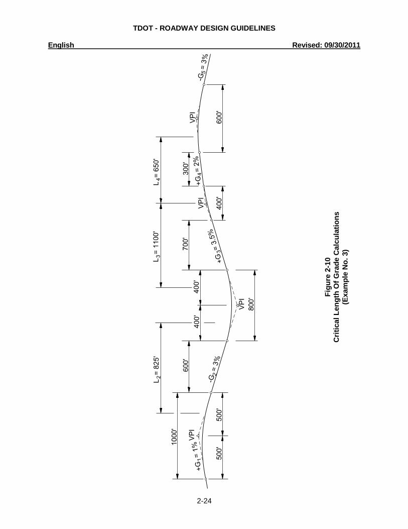
Example No. 3 Given: Figure 2-10 illustrates the vertical alignment on a low-volume, two-lane rural collector
highway with no large trucks. Problem: Determine if the critical length of grade is exceeded for G2 or for the combination
upgrade G3 and G4. Solution: Use the following steps: Step 1. Determine the length of grade using the criteria in Figure 2-9. For this example, the
following calculations are used:
ft 825 4
800 600 4
1000 L2 =++=
ft1100
2400 700
4800 L
3=++=
ft650 4
600 300 2
400 L4
=++=
Step 2. Determine the critical length of grade in both directions. Use Figure 2-8 to determine
the critical length of grade.
• For trucks traveling left to right, enter into Figure 2-8 the value for G3 (3.5%) and L3 = 1100 ft. The speed reduction is 7.0 mph. For G4 (2%) and L4 = 650 ft, the speed reduction is approximately 3.5 mph. The total speed reduction on the combination upgrade G3 and G4 is 10.5 mph. This exceeds the maximum 10 mph speed reduction. However, on low-volume roads, one can assume a 5 mph increase in truck speed for the 3% “momentum” grade (G2), which precedes G3. Therefore, a speed reduction may be as high as 15 mph before concluding that the combination grade exceeds the critical length of grade. Assuming the benefits of the momentum grade, this leads to the conclusion that the critical length of grade is not exceeded.
• For trucks traveling in the opposite direction, on Figure 2-8, enter in the value
for G2 (3%) and determine the critical length of grade for the 10 mph speed reduction (i.e., 1700 ft). Because L2 is less than 1700 ft (i.e., 825 ft), the critical length of grade for this direction is not exceeded.
TDOT - ROADWAY DESIGN GUIDELINES English Revised: 09/30/2011
2-24
Figu
re 2
-10
Crit
ical
Len
gth
Of G
rade
Cal
cula
tions
(E
xam
ple
No.
3)
TDOT - ROADWAY DESIGN GUIDELINES English Revised: 09/30/2011
2-25
2-150.04 DESIGN GUIDELINES
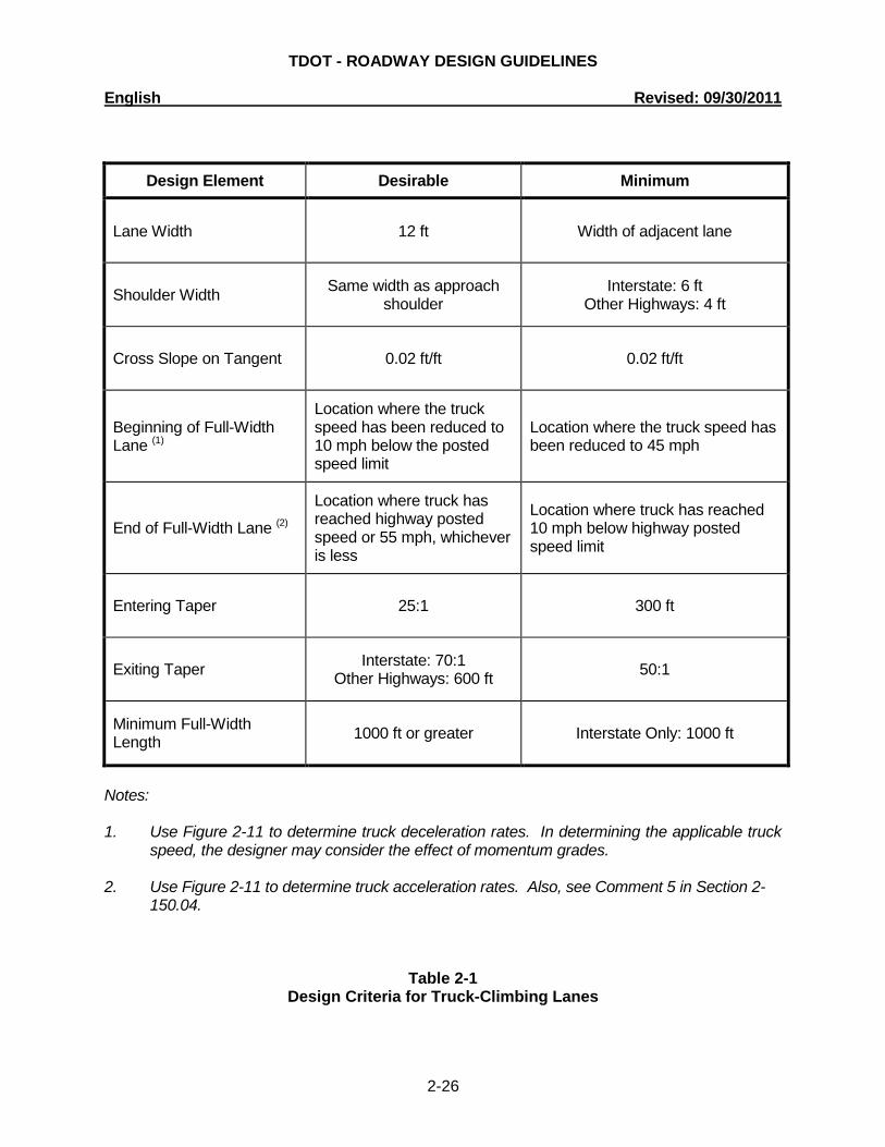
Table 2-1 summarizes the design criteria for a truck-climbing lane. Also, consider the following:
1. Design Speed – For entering speeds equal to or greater than 70 mph, use 70
mph for the truck design speed. For speeds less than 70 mph, use the roadway design speed or the posted speed limit, whichever is less. Under restricted conditions, the designer may want to consider the effect a momentum grade will have on the entering speed. See Comment 3 in Section 2-150.03 for additional information on momentum grades. However, the maximum speed will be 70 mph.
2. Cross Slope – On tangent sections, the truck-climbing lane cross slope will
typically be the same as that of the adjacent travel lane.
3. Superelevation – For horizontal curves, superelevate the truck-climbing lane at the same rate as the adjacent travel lane.
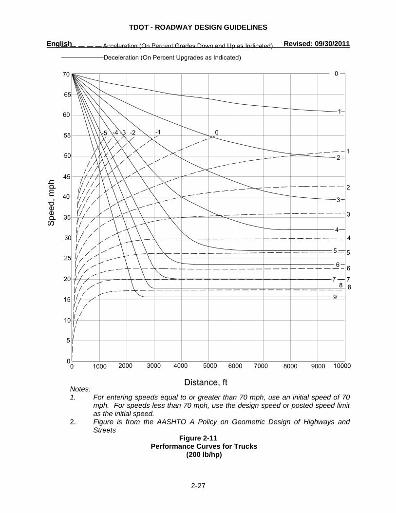
4. Performance Curves – Figure 2-11 presents the deceleration and acceleration
rates for a 200 lb/hp truck.
5. End of Full-Width Lane – In addition to the criteria in Table 2-1, ensure that there is sufficient sight distance available to the point where the truck, RV or bus will begin to merge back into the through travel lane. At a minimum, this will be stopping sight distance. Desirably, the driver should have decision sight distance available to the roadway surface (i.e., height of object = 0.0 ft) at the end of the taper. See the AASHTO A Policy on Geometric Design of Highways and Streets for decision sight distance values.
The full-lane width should be extended beyond the crest vertical curve and not ended just beyond the crest of the grade. Also, desirably the full-lane width should not end on a horizontal curve.
6. Signing and Pavement Markings – Contact the ITS, Traffic and Standards
Section for signing and pavement marking guidance for truck-climbing lanes.
TDOT - ROADWAY DESIGN GUIDELINES English Revised: 09/30/2011
2-26
Design Element Desirable Minimum
Lane Width 12 ft Width of adjacent lane
Shoulder Width Same width as approach shoulder
Interstate: 6 ft Other Highways: 4 ft
Cross Slope on Tangent 0.02 ft/ft 0.02 ft/ft
Beginning of Full-Width Lane (1)
Location where the truck speed has been reduced to 10 mph below the posted speed limit
Location where the truck speed has been reduced to 45 mph
End of Full-Width Lane (2)
Location where truck has reached highway posted speed or 55 mph, whichever is less
Location where truck has reached 10 mph below highway posted speed limit
Entering Taper 25:1 300 ft
Exiting Taper Interstate: 70:1 Other Highways: 600 ft 50:1
Minimum Full-Width Length 1000 ft or greater Interstate Only: 1000 ft
Notes: 1. Use Figure 2-11 to determine truck deceleration rates. In determining the applicable truck
speed, the designer may consider the effect of momentum grades. 2. Use Figure 2-11 to determine truck acceleration rates. Also, see Comment 5 in Section 2-
150.04.
Table 2-1 Design Criteria for Truck-Climbing Lanes
TDOT - ROADWAY DESIGN GUIDELINES English Revised: 09/30/2011
2-27
Notes:
1. For entering speeds equal to or greater than 70 mph, use an initial speed of 70 mph. For speeds less than 70 mph, use the design speed or posted speed limit as the initial speed.
2. Figure is from the AASHTO A Policy on Geometric Design of Highways and Streets
Figure 2-11 Performance Curves for Trucks
(200 lb/hp)
TDOT - ROADWAY DESIGN GUIDELINES English Revised: 09/30/2011
2-28
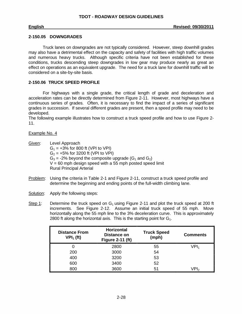
2-150.05 DOWNGRADES
Truck lanes on downgrades are not typically considered. However, steep downhill grades may also have a detrimental effect on the capacity and safety of facilities with high traffic volumes and numerous heavy trucks. Although specific criteria have not been established for these conditions, trucks descending steep downgrades in low gear may produce nearly as great an effect on operations as an equivalent upgrade. The need for a truck lane for downhill traffic will be considered on a site-by-site basis.
2-150.06 TRUCK SPEED PROFILE
For highways with a single grade, the critical length of grade and deceleration and acceleration rates can be directly determined from Figure 2-11. However, most highways have a continuous series of grades. Often, it is necessary to find the impact of a series of significant grades in succession. If several different grades are present, then a speed profile may need to be developed. The following example illustrates how to construct a truck speed profile and how to use Figure 2-11. Example No. 4 Given: Level Approach G1 = +3% for 800 ft (VPI to VPI) G2 = +5% for 3200 ft (VPI to VPI) G3 = -2% beyond the composite upgrade (G1 and G2) V = 60 mph design speed with a 55 mph posted speed limit Rural Principal Arterial Problem: Using the criteria in Table 2-1 and Figure 2-11, construct a truck speed profile and
determine the beginning and ending points of the full-width climbing lane. Solution: Apply the following steps: Step 1: Determine the truck speed on G1 using Figure 2-11 and plot the truck speed at 200 ft
increments. See Figure 2-12. Assume an initial truck speed of 55 mph. Move horizontally along the 55 mph line to the 3% deceleration curve. This is approximately 2800 ft along the horizontal axis. This is the starting point for G1.
Distance From VPI1 (ft)
Horizontal Distance on
Figure 2-11 (ft) Truck Speed
(mph) Comments
0 2800 55 VPI1 200 3000 54 400 3200 53 600 3400 52 800 3600 51 VPI2

TDOT - ROADWAY DESIGN GUIDELINES English Revised: 09/30/2011
2-29
Fi
gure
2-1
2 Tr
uck
Spee
d Pr
ofile
(E
xam
ple
No.
4)
TDOT - ROADWAY DESIGN GUIDELINES English Revised: 09/30/2011
2-30
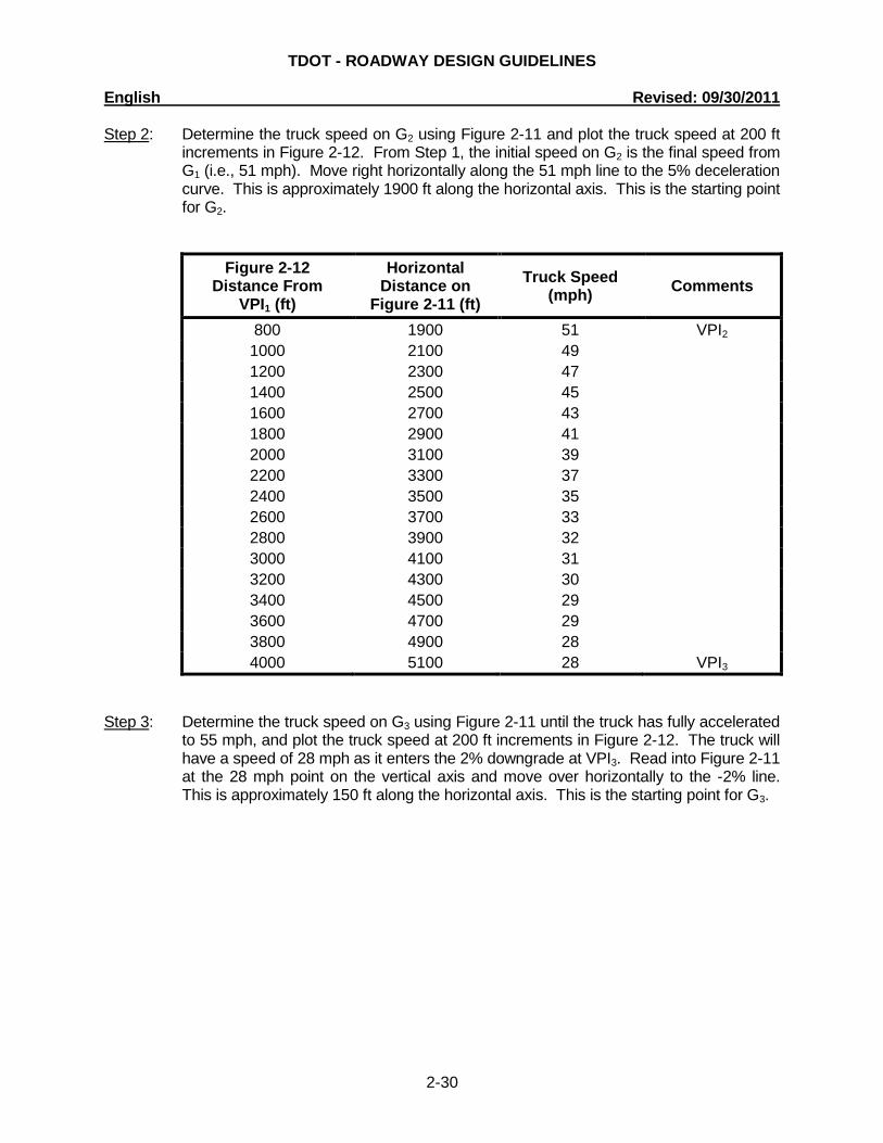
Step 2: Determine the truck speed on G2 using Figure 2-11 and plot the truck speed at 200 ft increments in Figure 2-12. From Step 1, the initial speed on G2 is the final speed from G1 (i.e., 51 mph). Move right horizontally along the 51 mph line to the 5% deceleration curve. This is approximately 1900 ft along the horizontal axis. This is the starting point for G2.
Figure 2-12 Distance From
VPI1 (ft)
Horizontal Distance on
Figure 2-11 (ft) Truck Speed
(mph) Comments
800 1900 51 VPI2 1000 2100 49 1200 2300 47 1400 2500 45 1600 2700 43 1800 2900 41 2000 3100 39 2200 3300 37 2400 3500 35 2600 3700 33 2800 3900 32 3000 4100 31 3200 4300 30 3400 4500 29 3600 4700 29 3800 4900 28 4000 5100 28 VPI3
Step 3: Determine the truck speed on G3 using Figure 2-11 until the truck has fully accelerated
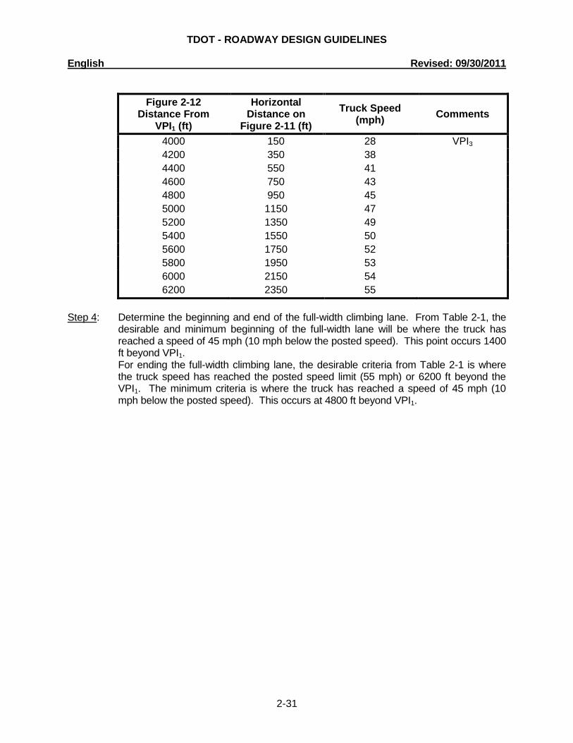
to 55 mph, and plot the truck speed at 200 ft increments in Figure 2-12. The truck will have a speed of 28 mph as it enters the 2% downgrade at VPI3. Read into Figure 2-11 at the 28 mph point on the vertical axis and move over horizontally to the -2% line. This is approximately 150 ft along the horizontal axis. This is the starting point for G3.
TDOT - ROADWAY DESIGN GUIDELINES English Revised: 09/30/2011
2-31
Figure 2-12
Distance From VPI1 (ft)
Horizontal Distance on
Figure 2-11 (ft) Truck Speed
(mph) Comments
4000 150 28 VPI3 4200 350 38 4400 550 41 4600 750 43 4800 950 45 5000 1150 47 5200 1350 49 5400 1550 50 5600 1750 52 5800 1950 53 6000 2150 54 6200 2350 55
Step 4: Determine the beginning and end of the full-width climbing lane. From Table 2-1, the
desirable and minimum beginning of the full-width lane will be where the truck has reached a speed of 45 mph (10 mph below the posted speed). This point occurs 1400 ft beyond VPI1.
For ending the full-width climbing lane, the desirable criteria from Table 2-1 is where the truck speed has reached the posted speed limit (55 mph) or 6200 ft beyond the VPI1. The minimum criteria is where the truck has reached a speed of 45 mph (10 mph below the posted speed). This occurs at 4800 ft beyond VPI1.
TDOT - ROADWAY DESIGN GUIDELINES English Revised: 09/30/2011
2-32
2-155.00 WETLANDS BOUNDARY DESIGNATION When a designer receives a project survey showing wetland involvement or the designer suspects wetland involvement, the designer shall send an email notification requesting wetland boundaries three weeks prior to the Preliminary Field Review (See Activity and Estimated Completion Schedule, A&E) to the Natural Resources Office of the Environmental Division. A copy of the e-mail shall be placed in the project folder to document the request of wetland boundaries. That division will mark the wetland boundaries on the plans and return them to the designer. The designer will then show the wetland boundaries on the plans. Wetland boundaries will be shown by the symbol on Standard Drawing RD-L-1. The word "WETLANDS" shall be placed inside the boundary. Wetlands located immediately adjacent to the project shall be identified on the plans, if wetlands will be affected by the roadway construction or possible wetland impacts are identified by the Environmental Division. The plans shall also indicate locations where roadway outfall discharges are modified and locations where the wetland receiving flows are redirected. The area (in square feet or acres) of any wetlands impacted by the project or any right-of-way taken for wetland replacement shall be indicated on the present layout sheet. 2-155.02 HAZARDOUS MATERIAL STUDY The designer shall send an email notification requesting a hazardous materials study for all projects requiring right-of-way acquisition three weeks prior to the Preliminary Field Review (See Activity and Estimated Completion Schedule, A&E) to the Hazardous Materials Section of the Environmental Division. A copy of the e-mail shall be placed in the project folder to document the request of a hazardous materials study. 2-155.05 BOX AND SLAB-TYPE CULVERT AND BRIDGE LENGTHS, CHANNEL
CHANGES, AND WETLANDS The following procedures and policies need to be followed in order to achieve an environmentally acceptable project as perceived by the Corps of Engineers, Environmental Protection Agency, United States Fish and Wildlife Service, Tennessee Wildlife Resources Agency, and Tennessee Department of Environment and Conservation: 1. Any project which proposes long expanses of boxes and/or channel
changes on blue-line streams and/or wetlands involvement must be studied for alternate solutions: after which, a project coordination meeting between the involved TDOT Divisions must be held.
2. Where box and slab-type culverts and bridges are employed, their length
shall be held to a minimum. In the case of interchanges, intermittent boxes, rather than continuous boxes, are preferred.
3. Given the choice between long runs of boxes and channel changes,
channel changes are generally preferred.
TDOT - ROADWAY DESIGN GUIDELINES English Revised: 09/30/2011
2-33
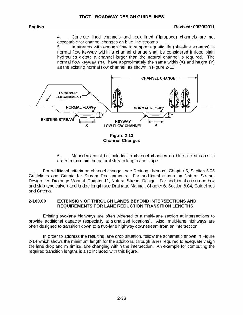
4. Concrete lined channels and rock lined (riprapped) channels are not acceptable for channel changes on blue-line streams.
5. In streams with enough flow to support aquatic life (blue-line streams), a normal flow keyway within a channel change shall be considered if flood plain hydraulics dictate a channel larger than the natural channel is required. The normal flow keyway shall have approximately the same width (X) and height (Y) as the existing normal flow channel, as shown in Figure 2-13.
Figure 2-13
Channel Changes
6. Meanders must be included in channel changes on blue-line streams in order to maintain the natural stream length and slope.
For additional criteria on channel changes see Drainage Manual, Chapter 5, Section 5.05 Guidelines and Criteria for Stream Realignments. For additional criteria on Natural Stream Design see Drainage Manual, Chapter 11, Natural Stream Design. For additional criteria on box and slab-type culvert and bridge length see Drainage Manual, Chapter 6, Section 6.04, Guidelines and Criteria. 2-160.00 EXTENSION OF THROUGH LANES BEYOND INTERSECTIONS AND
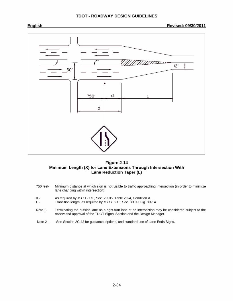
REQUIREMENTS FOR LANE REDUCTION TRANSITION LENGTHS Existing two-lane highways are often widened to a multi-lane section at intersections to provide additional capacity (especially at signalized locations). Also, multi-lane highways are often designed to transition down to a two-lane highway downstream from an intersection. In order to address the resulting lane drop situation, follow the schematic shown in Figure 2-14 which shows the minimum length for the additional through lanes required to adequately sign the lane drop and minimize lane changing within the intersection. An example for computing the required transition lengths is also included with this figure.
Y Y
X X EXISTING STREAM
NORMAL FLOW NORMAL FLOW
KEYWAY LOW FLOW CHANNEL
CHANNEL CHANGE
ROADWAY EMBANKMENT
Y
TDOT - ROADWAY DESIGN GUIDELINES English Revised: 09/30/2011
2-34
Figure 2-14 Minimum Length (X) for Lane Extensions Through Intersection With
Lane Reduction Taper (L)
750 feet- Minimum distance at which sign is not visible to traffic approaching intersection (in order to minimize
lane changing within intersection). d - As required by M.U.T.C.D., Sec. 2C.05, Table 2C-4, Condition A. L - Transition length, as required by M.U.T.C.D., Sec. 3B.09, Fig. 3B-14. Note 1- Terminating the outside lane as a right-turn lane at an intersection may be considered subject to the
review and approval of the TDOT Signal Section and the Design Manager.
Note 2 - See Section 2C.42 for guidance, options, and standard use of Lane Ends Signs.

TDOT - ROADWAY DESIGN GUIDELINES English Revised: 09/30/2011
2-35
To find “d” use the following table:
Posted or 85th-
Percentile Speed
Advance Placement Distance1 Condition A: Speed reduction and lane
changing in heavy traffic2
Condition B: Deceleration to the listed advisory speed (mph) for the condition
03 104 204 304 404 504 604 704
20 mph 225 ft 100 ft6 N/A5 - - - - - -
25 mph 325 ft 100 ft6 N/A5 N/A5 - - - - - 30 mph 460 ft 100 ft6 N/A5 N/A5 - - - - - 35 mph 565 ft 100 ft6 N/A5 N/A5 N/A5 - - - - 40 mph 670 ft 125 ft 100 ft6 100 ft6 N/A5 - - - - 45 mph 775 ft 175 ft 125 ft 100 ft6 100 ft6 N/A5 - - - 50 mph 885 ft 250 ft 200 ft 175 ft 125 ft 100 ft6 - - -
55 mph 990 ft 325 ft 275 ft 225 ft 200 ft 125 ft N/A5 - -
60 mph 1,100 ft 400 ft 350 ft 325 ft 275 ft 200 ft 100 ft6 - - 65 mph 1,200 ft 475 ft 450 ft 400 ft 350 ft 275 ft 200 ft 100 ft6 - 70 mph 1,250 ft 550 ft 525 ft 500 ft 450 ft 375 ft 275 ft 150 ft - 75 mph 1,350 ft 650 ft 625 ft 600 ft 550 ft 475 ft 375 ft 250 ft 100 ft6
Table 2-2
Guidelines for Advance Placement of Warning Signs Reference: M.U.T.C.D. 2009 Manual (Table 2C-4 of Section 2C.05)
Notes: 1The distances are adjusted for a sign legibility distance of 180 ft for Condition A. The distances for Condition B have been adjusted for a sign legibility distance of 250 feet, which is appropriate for an alignment warning symbol sign. For Conditions A and B, warning signs with less than 6-inch legend or more than four words, a minimum of 100 feet should be added to the advance placement distance to provide adequate legibility of the warning sign.
2Typical conditions are locations where the road user must use extra time to adjust speed and change lanes in heavy traffic because of a complex driving situation. Typical signs are Merge and Right Lane Ends. The distances are determined by providing the driver a PRT of 14.0 to 14.5 seconds for vehicle maneuvers (2005 AASHTO Policy, Exhibit 3-3, Decision Sight Distance, Avoidance Maneuver E) minus the legibility distance of 180 feet for the appropriate sign.
3Typical condition is the warning of a potential stop situation. Typical signs are Stop Ahead, Yield Ahead, Signal Ahead, and Intersection Warning signs. The distances are based on the 2005 AASHTO Policy, Exhibit 3-1, Stopping Sight Distance, providing a PRT of 2.5 seconds, a deceleration rate of 11.2 feet/second2, minus the sign legibility distance of 180 feet.

TDOT - ROADWAY DESIGN GUIDELINES English Revised: 09/30/2011
2-36
4Typical conditions are locations where the road user must decrease speed to maneuver through the warned condition. Typical signs are Turn, Curve, Reverse Turn, or Reverse Curve. The distance is determined by providing a 2.5 second PRT, a vehicle deceleration rate of 10 feet/second2, minus the sign legibility distance of 250 ft.
5No suggested distances are provided for these speeds, as the placement location is dependent on site conditions and other signing. An alignment warning sign may be placed anywhere from the point of curvature up to 100 feet in advance of the curve. However, the alignment warning sign should be installed in advance of the curve and at least 100 feet from any other signs. 6The minimum advance placement distance is listed as 100 feet to provide adequate spacing between signs.
TDOT - ROADWAY DESIGN GUIDELINES English Revised: 09/30/2011
2-37
EXAMPLE: Posted speed = 55 mph X = 750 feet + d = 750 feet + 700 feet = 1,450 feet L = S x W (for speed 45 mph or more) = 55 x 18 = 990 feet 2-165.00 TWO-LANE ENTRANCE RAMPS ON FREEWAYS AND EXPRESSWAYS Designers shall use the parallel design when introducing two-lane entrance ramps to freeways and expressways. The parallel design is preferable for two reasons: (1) Past experience with the tapered design has been undesirable from an operational and safety standpoint; (2) Uniformity of design due to the fact that most two-lane entrance ramps statewide are the parallel type. For examples of the parallel design for two-lane entrance ramps, refer to A Policy on Geometric Design of Highways and Streets, AASHTO, 2001, Pages 816 and 858 (Exhibits 10-52, A2 and 10-69, B). 2-170.00 GUIDELINES FOR DESIGN OF TURNING LANES These guidelines are intended to assist the designer in designing left and right-turn lanes at intersections. These guidelines provide information on material included in the AASHTO's A Policy on Geometric Design of Highways and Streets, 2001 and are an attempt to consolidate that information regarding the design of turn lanes. The benefits of turn lanes at intersections are obvious in improved capacity and safety. These guidelines are applicable to right and left-turn lanes, and give procedures for desirable design. Design may be limited by geometric or other constraints, but these guidelines shall be followed as closely as possible.
TDOT - ROADWAY DESIGN GUIDELINES English Revised: 09/30/2011
2-38
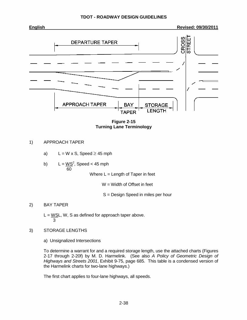
Figure 2-15
Turning Lane Terminology
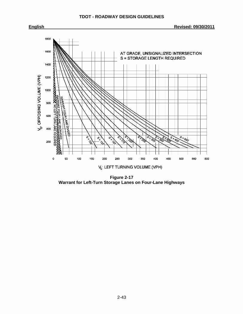
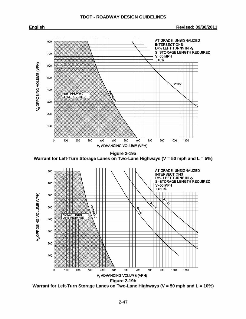
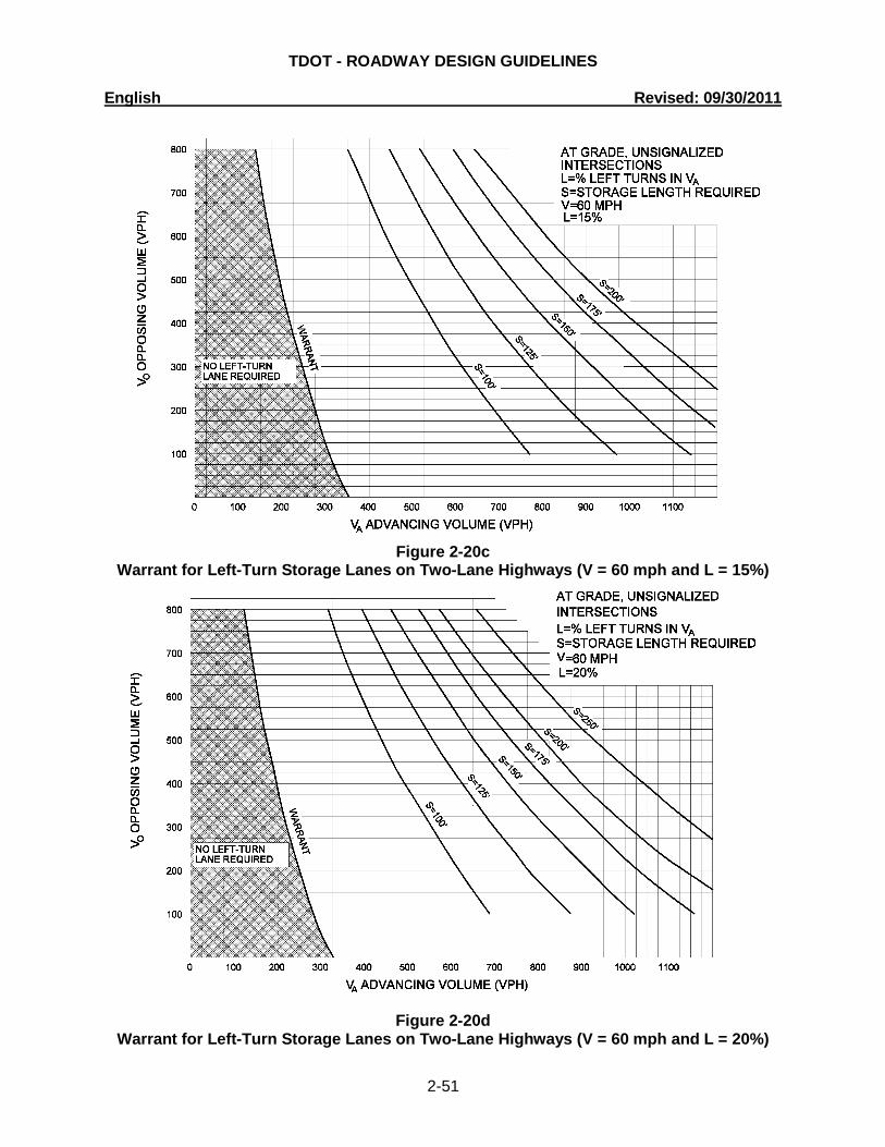
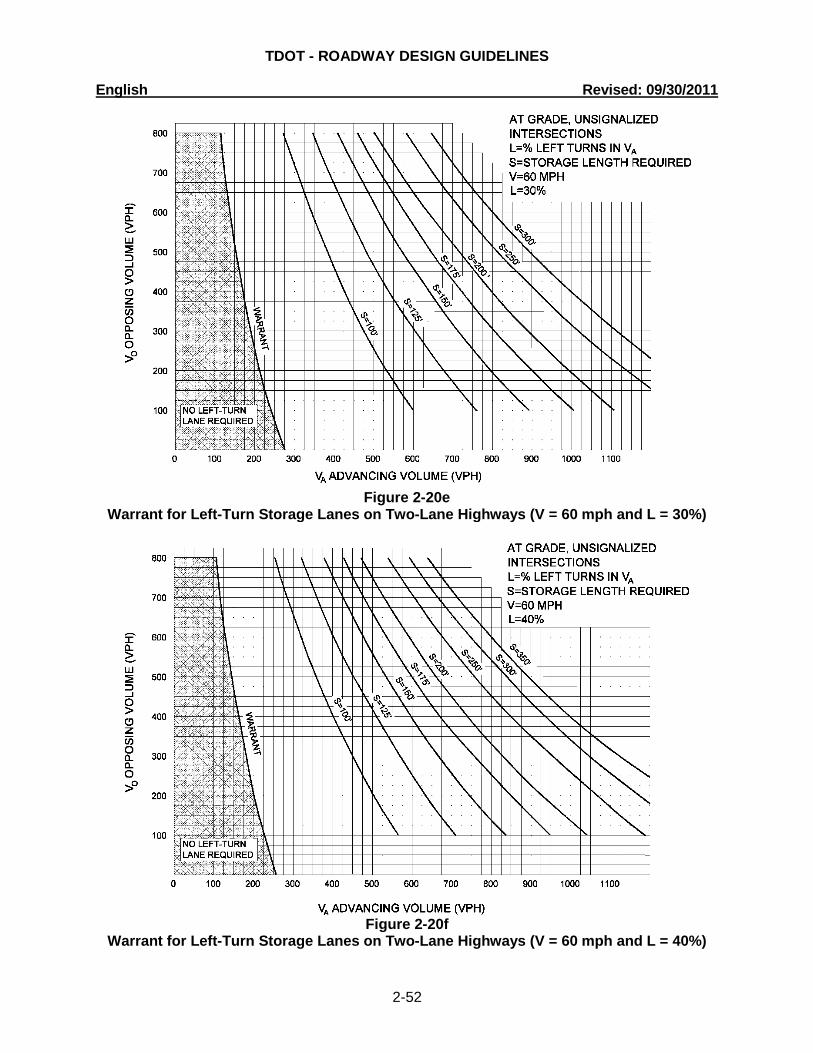
1) APPROACH TAPER a) L = W x S, Speed ≥ 45 mph b) L = WS2, Speed < 45 mph 60 Where L = Length of Taper in feet W = Width of Offset in feet S = Design Speed in miles per hour 2) BAY TAPER L = WS L, W, S as defined for approach taper above. 3 3) STORAGE LENGTHS a) Unsignalized Intersections To determine a warrant for and a required storage length, use the attached charts (Figures
2-17 through 2-20f) by M. D. Harmelink. (See also A Policy of Geometric Design of Highways and Streets 2001, Exhibit 9-75, page 685. This table is a condensed version of the Harmelink charts for two-lane highways.)
The first chart applies to four-lane highways, all speeds.
TDOT - ROADWAY DESIGN GUIDELINES English Revised: 09/30/2011
2-39
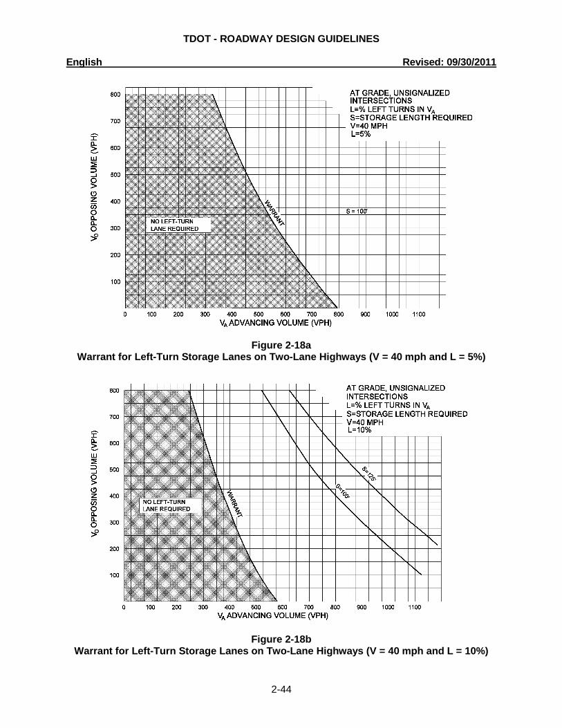
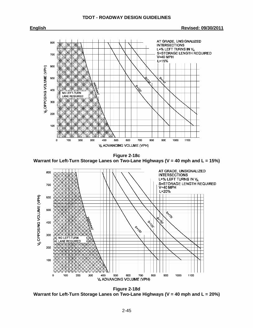
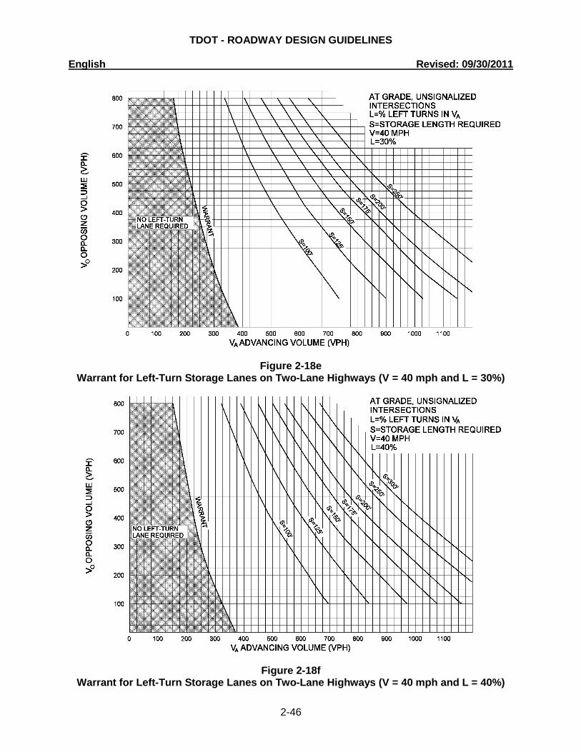
The remaining charts are a function of speed and the percentage of lefts in the approaching traffic, and are applicable only to two-lane highways. Select the appropriate chart for design speed and percentage of left turns. Use the total advancing volume for the approach (left, through, and right) on the bottom axis of the chart, and the total opposing volume on the left axis of the chart.
b) Signalized Intersections Storage lengths at signalized intersections are a function of signal timings, volumes, and
saturation flow rates. Assistance in determining storage lengths can be provided by the Design Traffic Engineering Section, Signal and Lighting Office.
4) DEPARTURE TAPER The departure taper begins at the end of the storage lane and ends at the beginning of the
approach taper. SOME SPECIAL NOTES:
i) When the left-turn volume exceeds 300 vph, a double left-turn lane shall be considered. A capacity analysis will help determine the benefit of an additional lane. If a double left is proposed, use 60% of the turn volume to determine the storage length for each lane.
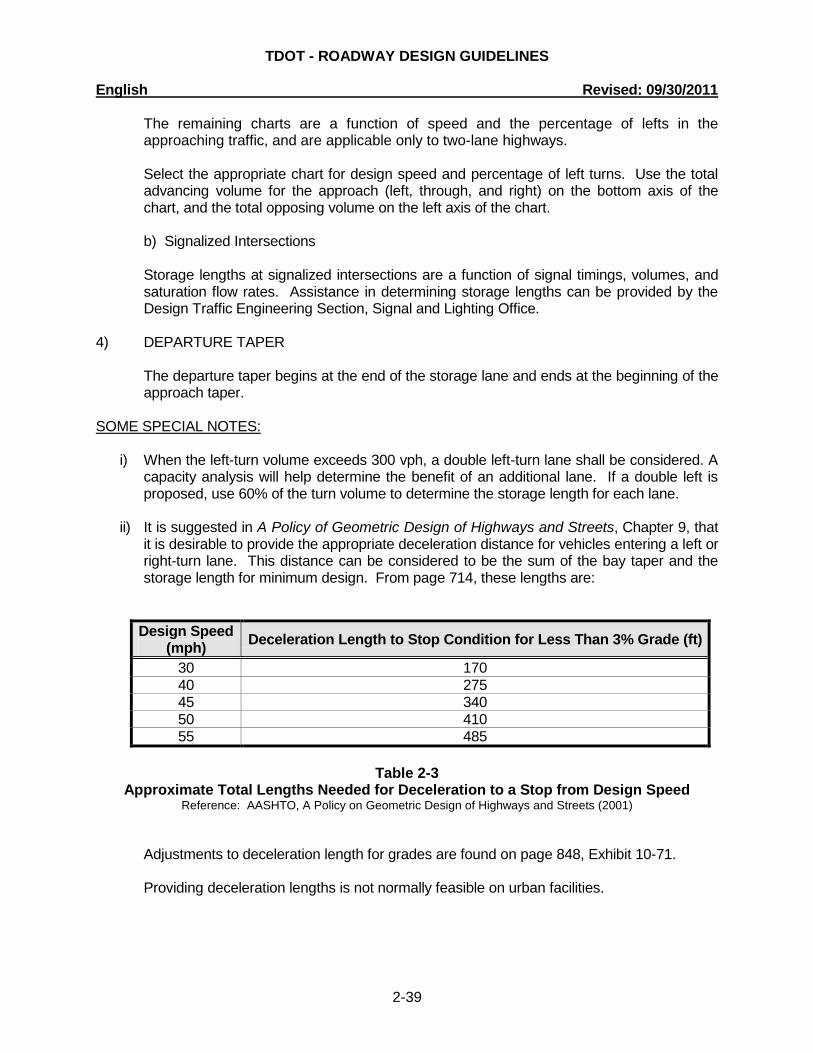
ii) It is suggested in A Policy of Geometric Design of Highways and Streets, Chapter 9, that
it is desirable to provide the appropriate deceleration distance for vehicles entering a left or right-turn lane. This distance can be considered to be the sum of the bay taper and the storage length for minimum design. From page 714, these lengths are:
Design Speed (mph) Deceleration Length to Stop Condition for Less Than 3% Grade (ft)
30 170 40 275 45 340 50 410 55 485
Table 2-3
Approximate Total Lengths Needed for Deceleration to a Stop from Design Speed Reference: AASHTO, A Policy on Geometric Design of Highways and Streets (2001)
Adjustments to deceleration length for grades are found on page 848, Exhibit 10-71. Providing deceleration lengths is not normally feasible on urban facilities.
TDOT - ROADWAY DESIGN GUIDELINES English Revised: 09/30/2011
2-40
When the deceleration length is to be provided, and this length exceeds the bay taper plus storage length, the additional length shall be provided as storage and the bay taper kept constant.
iii) As suggested in the 2000 Highway Capacity Manual (HCM2000), page 10-18, exclusive
right-turn lanes shall be considered when the right-turn volume exceeds 300 vph and the adjacent thru-lane volume also exceeds 300 vphpl. A capacity analysis will also provide a measure of the benefits of a right-turn lane to the overall intersection operation.
iv) It shall be noted that at some intersections, lengths of turn lanes may be more a function
of queue lengths in through lanes that might block access to turn lanes, thus reducing turn lane efficiency.
5) LOCATION OF LEFT-TURN LANES IN MEDIANS As discussed in A Policy of Geometric Design of Highways and Streets, Chapter 9, it is
desirable to align left-turn lanes in medians. The advantages of this placement are:
i) Better visibility of opposing through traffic as left turners look for gaps. ii) Decreased conflict between opposing left-turn vehicle paths. iii) Increased numbers of left-turn vehicles served in a given period of time. The farther left
the turn lane, the shorter the crossing distance for left-turn vehicles, allowing drivers to choose shorter gaps in opposing traffic and clear the intersection. There is also an increase in capacity at signalized intersections, due to more flexibility in left-turn phasing and shorter clearance intervals.
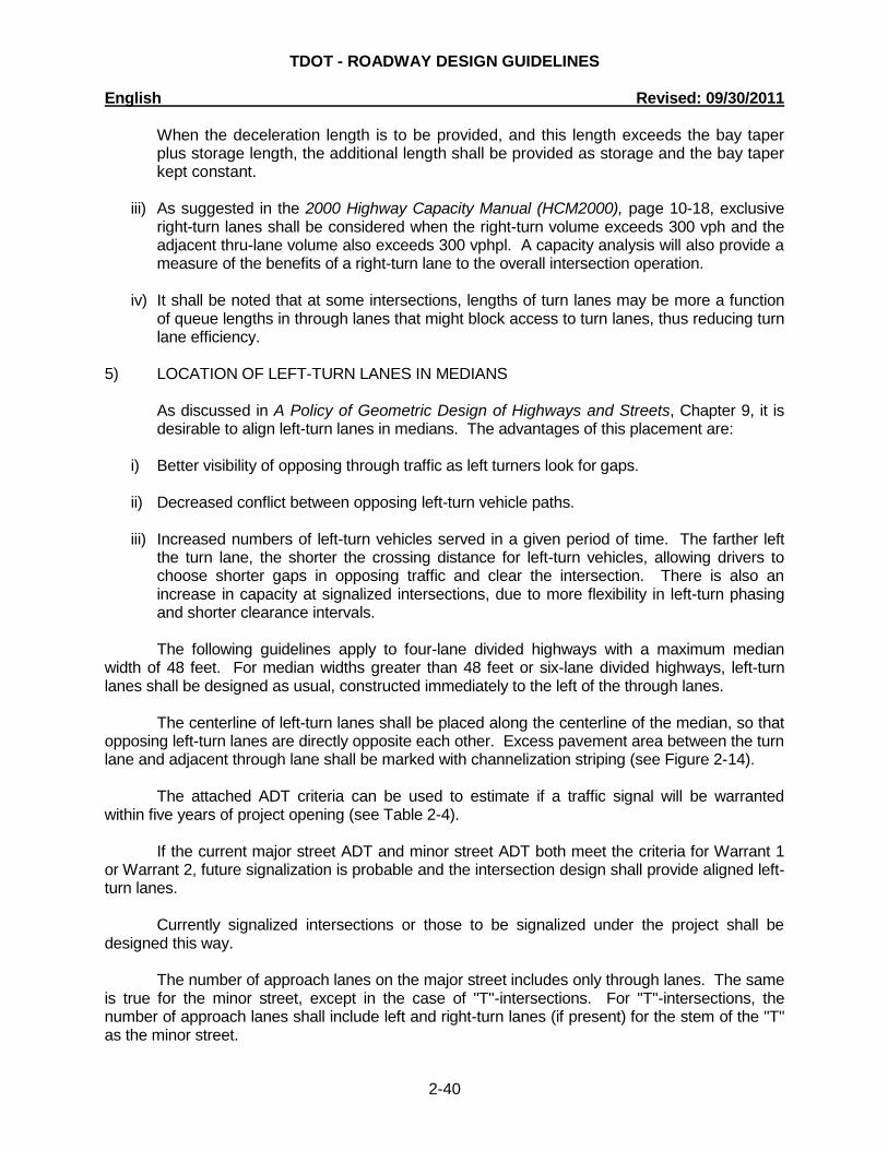
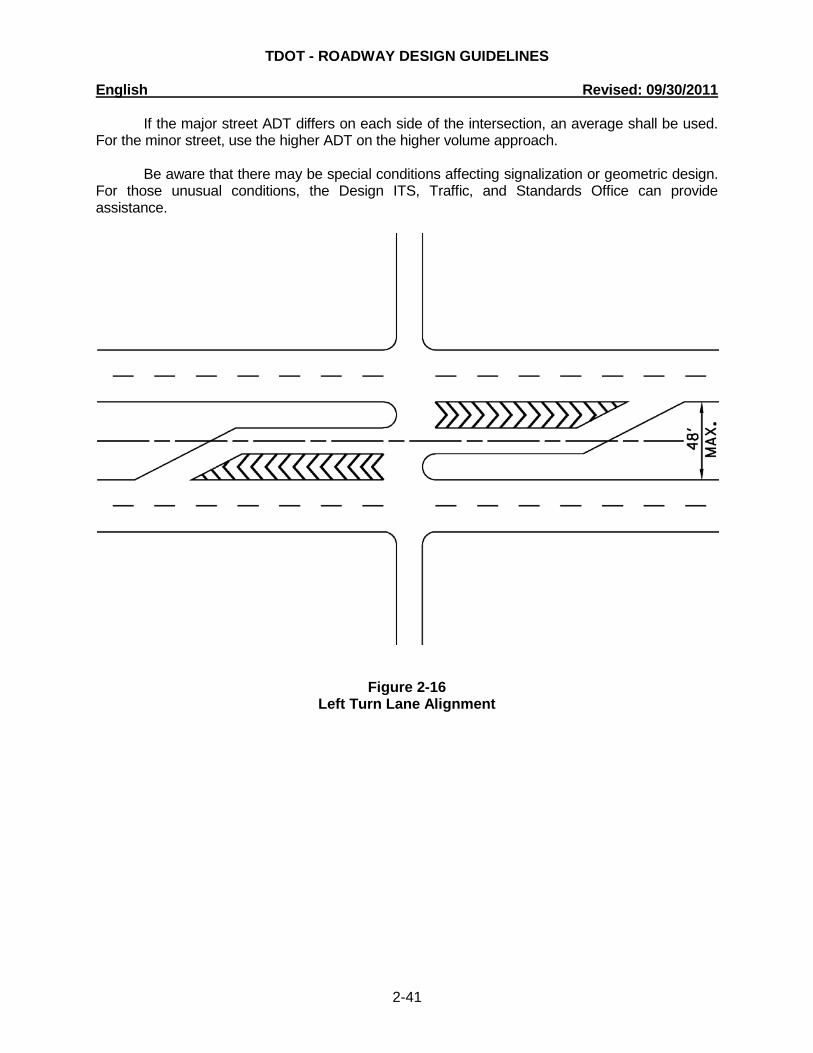
The following guidelines apply to four-lane divided highways with a maximum median width of 48 feet. For median widths greater than 48 feet or six-lane divided highways, left-turn lanes shall be designed as usual, constructed immediately to the left of the through lanes. The centerline of left-turn lanes shall be placed along the centerline of the median, so that opposing left-turn lanes are directly opposite each other. Excess pavement area between the turn lane and adjacent through lane shall be marked with channelization striping (see Figure 2-14). The attached ADT criteria can be used to estimate if a traffic signal will be warranted within five years of project opening (see Table 2-4). If the current major street ADT and minor street ADT both meet the criteria for Warrant 1 or Warrant 2, future signalization is probable and the intersection design shall provide aligned left-turn lanes. Currently signalized intersections or those to be signalized under the project shall be designed this way. The number of approach lanes on the major street includes only through lanes. The same is true for the minor street, except in the case of "T"-intersections. For "T"-intersections, the number of approach lanes shall include left and right-turn lanes (if present) for the stem of the "T" as the minor street.
TDOT - ROADWAY DESIGN GUIDELINES English Revised: 09/30/2011
2-41
If the major street ADT differs on each side of the intersection, an average shall be used. For the minor street, use the higher ADT on the higher volume approach.
Be aware that there may be special conditions affecting signalization or geometric design. For those unusual conditions, the Design ITS, Traffic, and Standards Office can provide assistance.
Figure 2-16 Left Turn Lane Alignment
TDOT - ROADWAY DESIGN GUIDELINES English Revised: 09/30/2011
2-42
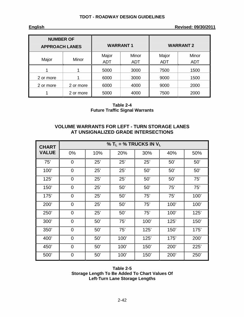
NUMBER OF APPROACH LANES
WARRANT 1
WARRANT 2
Major
Minor
Major ADT
Minor ADT
Major ADT
Minor ADT
1 1 5000 3000 7500 1500
2 or more 1 6000 3000 9000 1500
2 or more 2 or more 6000 4000 9000 2000
1 2 or more 5000 4000 7500 2000
Table 2-4 Future Traffic Signal Warrants
VOLUME WARRANTS FOR LEFT - TURN STORAGE LANES AT UNSIGNALIZED GRADE INTERSECTIONS
CHART VALUE
% TL = % TRUCKS IN VL
0% 10% 20% 30% 40% 50%
75’ 0 25’ 25’ 25’ 50’ 50’
100’ 0 25’ 25’ 50’ 50’ 50’
125’ 0 25’ 25’ 50’ 50’ 75’
150’ 0 25’ 50’ 50’ 75’ 75’
175’ 0 25’ 50’ 75’ 75’ 100’
200’ 0 25’ 50’ 75’ 100’ 100’
250’ 0 25’ 50’ 75’ 100’ 125’
300’ 0 50’ 75’ 100’ 125’ 150’
350’ 0 50’ 75’ 125’ 150’ 175’
400’ 0 50’ 100’ 125’ 175’ 200’
450’ 0 50’ 100’ 150’ 200’ 225’
500’ 0 50’ 100’ 150’ 200’ 250’
Table 2-5
Storage Length To Be Added To Chart Values Of Left-Turn Lane Storage Lengths
TDOT - ROADWAY DESIGN GUIDELINES English Revised: 09/30/2011
2-43
Figure 2-17 Warrant for Left-Turn Storage Lanes on Four-Lane Highways
TDOT - ROADWAY DESIGN GUIDELINES English Revised: 09/30/2011
2-44
Figure 2-18a Warrant for Left-Turn Storage Lanes on Two-Lane Highways (V = 40 mph and L = 5%)
Figure 2-18b Warrant for Left-Turn Storage Lanes on Two-Lane Highways (V = 40 mph and L = 10%)
TDOT - ROADWAY DESIGN GUIDELINES English Revised: 09/30/2011
2-45
Figure 2-18c Warrant for Left-Turn Storage Lanes on Two-Lane Highways (V = 40 mph and L = 15%)
Figure 2-18d Warrant for Left-Turn Storage Lanes on Two-Lane Highways (V = 40 mph and L = 20%)
TDOT - ROADWAY DESIGN GUIDELINES English Revised: 09/30/2011
2-46
Figure 2-18e Warrant for Left-Turn Storage Lanes on Two-Lane Highways (V = 40 mph and L = 30%)
Figure 2-18f Warrant for Left-Turn Storage Lanes on Two-Lane Highways (V = 40 mph and L = 40%)
TDOT - ROADWAY DESIGN GUIDELINES English Revised: 09/30/2011
2-47
Figure 2-19a
Warrant for Left-Turn Storage Lanes on Two-Lane Highways (V = 50 mph and L = 5%)
Figure 2-19b
Warrant for Left-Turn Storage Lanes on Two-Lane Highways (V = 50 mph and L = 10%)
TDOT - ROADWAY DESIGN GUIDELINES English Revised: 09/30/2011
2-48
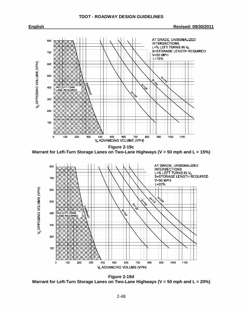
Figure 2-19c
Warrant for Left-Turn Storage Lanes on Two-Lane Highways (V = 50 mph and L = 15%)
Figure 2-19d Warrant for Left-Turn Storage Lanes on Two-Lane Highways (V = 50 mph and L = 20%)
TDOT - ROADWAY DESIGN GUIDELINES English Revised: 09/30/2011
2-49
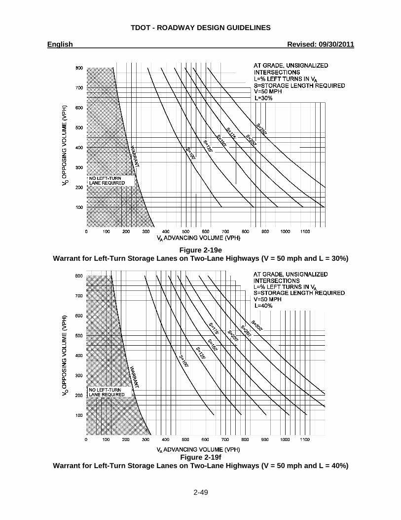
Figure 2-19e
Warrant for Left-Turn Storage Lanes on Two-Lane Highways (V = 50 mph and L = 30%)
Figure 2-19f
Warrant for Left-Turn Storage Lanes on Two-Lane Highways (V = 50 mph and L = 40%)
TDOT - ROADWAY DESIGN GUIDELINES English Revised: 09/30/2011
2-50
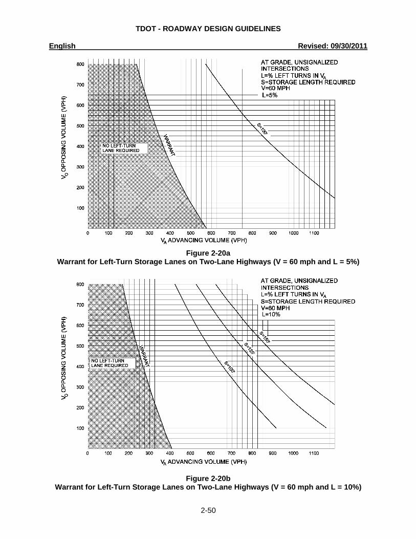
Figure 2-20a
Warrant for Left-Turn Storage Lanes on Two-Lane Highways (V = 60 mph and L = 5%)
Figure 2-20b Warrant for Left-Turn Storage Lanes on Two-Lane Highways (V = 60 mph and L = 10%)
TDOT - ROADWAY DESIGN GUIDELINES English Revised: 09/30/2011
2-51
Figure 2-20c
Warrant for Left-Turn Storage Lanes on Two-Lane Highways (V = 60 mph and L = 15%)
Figure 2-20d Warrant for Left-Turn Storage Lanes on Two-Lane Highways (V = 60 mph and L = 20%)
TDOT - ROADWAY DESIGN GUIDELINES English Revised: 09/30/2011
2-52
Figure 2-20e
Warrant for Left-Turn Storage Lanes on Two-Lane Highways (V = 60 mph and L = 30%)
Figure 2-20f
Warrant for Left-Turn Storage Lanes on Two-Lane Highways (V = 60 mph and L = 40%)

TDOT - ROADWAY DESIGN GUIDELINES English Revised: 09/30/2011
2-53
2-175.00 GUIDELINES FOR DETERMINING AND PROPOSING RETAINING WALLS For all design projects that contain retaining walls or that could potentially contain retaining walls, the responsibilities of the Design Division in relation to proposing a retaining wall design shall be as follows:
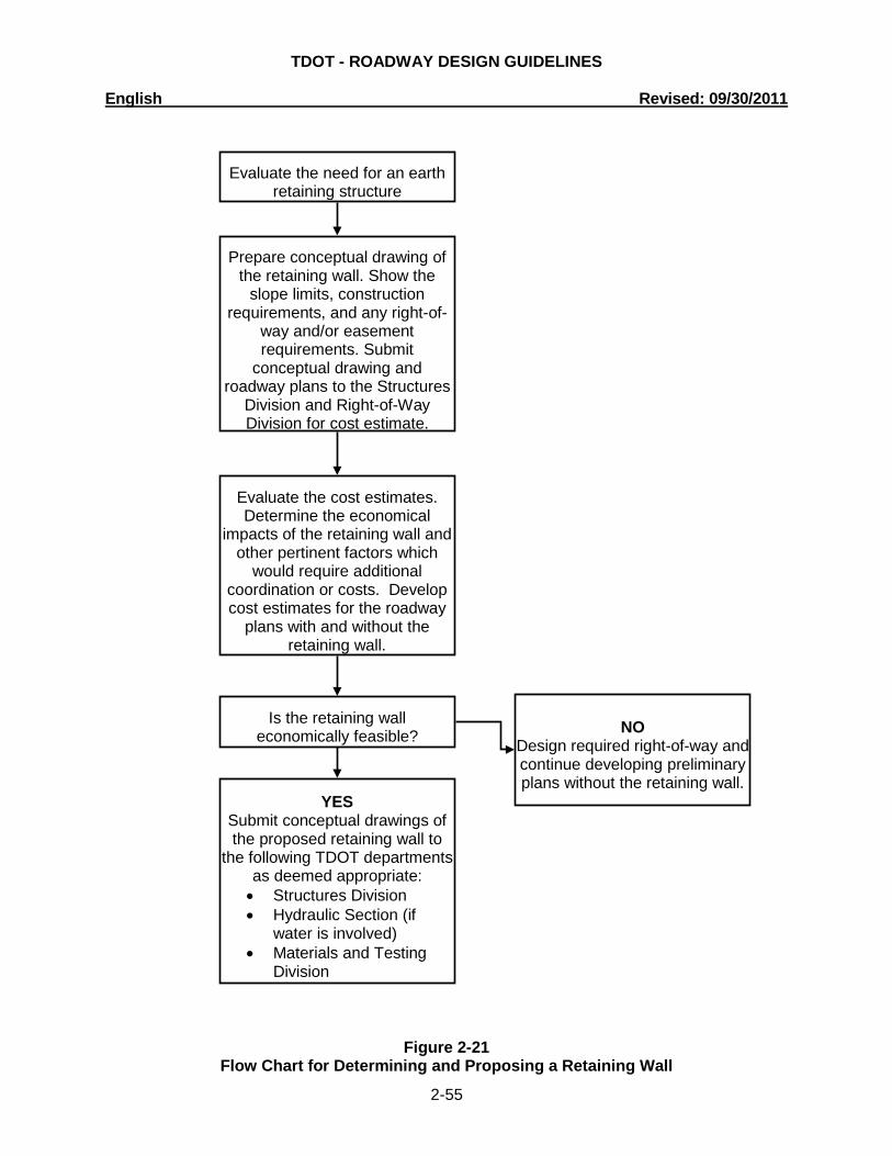
1. During the development of many roadway design projects, proposing a retaining wall is necessary due to right-of-way limitations, environmental impacts, drainage issues, or the need to reduce damage to adjacent properties. In most cases, a cost evaluation may be needed to justify a retaining wall. For those cases, the Designer should prepare a conceptual drawing in accordance with the Earth Retaining Structures Manual, Chapter 1, Section 3.0 - Conceptual Drawing Preparation. Right-of-way needs, including construction requirements, are to be clearly defined and shaded on the conceptual drawing and the roadway plans. The conceptual drawing and plans should be e-mailed to the Structures Division and Right-of-Way Division for cost estimates evaluating the economics of the proposed retaining wall.
After receiving the estimates, the Design Manager and the Designer determine if the retaining wall will be cost effective. If the retaining wall is cost effective or is required for other reasons or compelling factors such as environmental considerations, continue to prepare roadway plans with the retaining wall and complete step 2, below. When environmental factors are involved it may also be necessary to coordinate with the Environmental Division.
2. The roadway plans and the conceptual drawing should be e-mailed to the Structures Division, Hydraulic Section (if water is involved), and the Materials and Tests Division as appropriate. The submittal package should include the standard Letter of Transmittal provided in Appendix C of the Earth Retaining Structures Manual.
The flow chart in Figure 2-21 depicts the Design Division’s responsibilities with regard to
determining and proposing a retaining wall. For all proposed retaining wall submittals, a proposed retaining wall request packet shall
be e-mailed to the appropriate divisions. Each person listed in the CC section of the letter of transmittal should be copied on the email along with the design manager. A copy of the e-mail and retaining wall packet shall be placed in the project folder to document the submittal of the retaining wall request. The proposed retaining wall packet shall consist of a single pdf file that contains the letter of transmittal (shown in Appendix C of the Earth Retaining Structures Manual), the conceptual drawing and a set of plans, as appropriate.
The naming convention for the proposed retaining wall request packet will include the
PIN and the Region #, XXXXXX-XX-RetainingWallRequest-RegX.pdf. If there are modifications, including submitting additional information, then the naming convention will be XXXXXX-XX-RetainingWallRequest-RegX-Rev-00-00-00.pdf. Revised proposed retaining wall request will contain the packet in its entirety – i.e. letter, conceptual drawing, and plans.
Example: 123456-00-RetainingWallRequest-Reg1.pdf When assembling the pdf file, select small file size of default file size in Adobe Acrobate
Standard in order to keep the proposed retaining wall request packet under the 15MB email
TDOT - ROADWAY DESIGN GUIDELINES English Revised: 09/30/2011
2-54
limit. If the file exceeds 15 MB, the designer should split the packet into multiple emails and add Part 1, Part 2, etc. to the naming convention.
Example: 123456-00-RetainingWallRequest-Reg1-Part1.pdf For the Roadway Plans prepared by consultants, the proposed retaining wall request
packet should be prepared as described above and e-mailed to the Roadway Design Manager for review. Upon acceptance, the design manager will forward the package to the appropriate divisions.
The proposed retaining wall packet should be resubmitted whenever major design
revisions are made that could affect the pavement design as determined by the Design Manager.
TDOT - ROADWAY DESIGN GUIDELINES English Revised: 09/30/2011
2-55
Figure 2-21
Flow Chart for Determining and Proposing a Retaining Wall
Evaluate the need for an earth retaining structure
Prepare conceptual drawing of the retaining wall. Show the
slope limits, construction requirements, and any right-of-
way and/or easement requirements. Submit
conceptual drawing and roadway plans to the Structures
Division and Right-of-Way Division for cost estimate.
Evaluate the cost estimates. Determine the economical
impacts of the retaining wall and other pertinent factors which
would require additional coordination or costs. Develop cost estimates for the roadway
plans with and without the retaining wall.
YES Submit conceptual drawings of the proposed retaining wall to
the following TDOT departments as deemed appropriate: • Structures Division • Hydraulic Section (if
water is involved) • Materials and Testing
Division
Is the retaining wall economically feasible? NO
Design required right-of-way and continue developing preliminary plans without the retaining wall.
TDOT - ROADWAY DESIGN GUIDELINES English Revised: 09/30/2011
2-56
2-180.00 LOCATION OF AUTOMATIC TRAFFIC RECORDERS (ATR) AND ROADWAY WEATHER INFORMATION SYSTEMS (RWIS) ON PROJECTS
In order to avoid damage to Automatic Traffic Recorder (ATR) and RWIS Weather Station (RWIS) equipment that might be located within the limits of TDOT projects, the Design Division has been requested to identify equipment for ATR’s or RWIS’s located within the project limits during development of project plans. On projects developed in-house, it will be the responsibility of the designer to make this determination. On projects developed by consultants, it will be the responsibility of the TDOT Design Manager.
To determine whether an ATR is located within a project, check TRIMS using the standard query “ATR Locations” (statewide) or “ATR Locations by Region”. The county, route and log mile location for each respective ATR is listed. Please note that if you use the “ATR Locations by Region” query you must enter the correct region number under Value in the criteria window at the bottom. The query will also provide RWIS Weather Station information if a RWIS is also located at the ATR location.
If an ATR is found within a project, notify Director of Project Planning Divisionwith a
description of the proposed work in the vicinity of the ATR location. If the work on the project is likely to affect the operation of the ATR equipment, the roadway designer will be given a list of item numbers and descriptions for inclusion in the construction plans quantity block.
To determine whether a RWIS Weather Station is located within a project, check TRIMS
using the standard query “RWIS Locations”. The county, route and log mile for each RWIS location is listed statewide. The query will list stand alone RWIS sites and RWIS sites located at ATR locations.
If a RWIS is found within a project, notify the Manager of Asset Management Section of
the Maintenance Division. He will determine if the equipment will be affected by the work and arrange for the equipment to be replaced or advise the designer of appropriate items to include the plans to replace the affected equipment.
If inclusion of construction items is required and the project includes any traffic signal
work, notify the Manager of Design ITS, Traffic, and Standards Office in order to avoid possible duplication of construction items.

TDOT - ROADWAY DESIGN GUIDELINES English Revised: 09/30/2011
2-57
CHAPTER 2 – DRAINAGE
2-200.00 DRAINAGE MANUAL
In order to assist the designer performing drainage and hydrologic design, the Design Division has developed a Drainage Manual to provide a collection of applicable drainage criteria, policies and examples. The Manual discusses Tennessee Department of Transportation policies, practices and procedures for performing drainage design and hydraulic analyses on projects that are the responsibility of TDOT. Designers shall use Chapters 1-11 of the Design Division Drainage Manual for all projects designed or constructed by TDOT. These chapters include:
Chapter 1 Introduction Chapter 2 General Drainage Polices and Practices Chapter 3 Drainage Plan Requirements Chapter 4 Hydrology Chapter 5 Roadside Ditches and Streams Chapter 6 Culverts Chapter 7 Storm Drainage Systems Chapter 8 Stormwater Storage Facilities Chapter 9 Energy Dissipators Chapter 10 Erosion Prevention and Sediment Control Chapter 11 Natural Stream Design Limited copies of the manual will be distributed for internal use only. Consultants and
other interested persons may download the Manual from the TDOT Internet site. The Manual can be found at: http://www.tdot.state.tn.us/Chief_Engineer/assistant_engineer_design/design/DrainManChap%201-11.htm 2-200.01 COMPUTATION OF DRAINAGE
See Chapter 4 of the Drainage Manual. 2-200.05 DRAINAGE TABLES AND CHARTS
See Chapter 4 of the Drainage Manual. 2-200.10 EXAMPLE DRAINAGE PROBLEMS See Chapter 4 of the Drainage Manual.
TDOT - ROADWAY DESIGN GUIDELINES English Revised: 09/30/2011
2-58
CHAPTER 3 - RIGHT -OF-WAY 2-300.00 R.O.W. NOTES FOR ALL R.O.W. PROJECTS (See 3-305.00 and 6-140.00) All the notes below, which apply, will be put on the first property map sheet or first present layout sheet of the Right-of-Way Plans.
1. It is intended that all buildings and/or portions of buildings that are within the proposed right-of-way and/or easement lines for the project, be removed in the process of right-of-way acquisition. If any such buildings or improvements are not removed in the course of right-of-way acquisition, the Design Manager, Design Division (and Design Manager, Regional Design Office, if plans are being developed in the Regional Office) is/are to be notified in sufficient time to permit having such removals designated as a part of the construction contract.
2. All ramps must conform to the Department's "Policy on Financing Construction on
Public Road Intersections and Driveways on Highway Resurfacing, Reconstruction and Construction Projects on New Locations", The Manual on Rules and Regulations for Constructing Driveways on State Highway Right-of-Way, Standard Drawing RP-R-1, and other accepted design and safety standards.
2-300.05 R.O.W. NOTES ON PLANS REGARDING DRIVEWAYS (See 3-305.05, 3-
310.00, and 6-140.00)
See Figures 2-22 through 2-24 for examples of how to show driveways on plans. All ramp profiles (private drives, field entrances, business entrances, private and public side roads) shall be ploted on mylar cross-section sheets. All the notes below, which apply, will be put on the first property map sheet or the first present layout sheet of the Right-of-Way Plans.
1. New or Reconstruction Projects - with partial access control -
A. Existing paved driveway per tract remainder will be replaced in-kind to a touchdown point.
B. Where the existing driveway is unpaved and the proposed driveway
exceeds 7 percent in grade, each driveway will be paved to a touchdown point or until the grade is less than 7 percent.
C. Where the existing driveway is unpaved and the proposed driveway is less
than 7 percent in grade, each driveway will be paved a shoulder width from the edge of pavement and the remainder of that driveway replaced in-kind to a touchdown point.
D. Any necessary paving of driveways will be done during paving operations
on the main roadway.
TDOT - ROADWAY DESIGN GUIDELINES English Revised: 09/30/2011
2-59
E. Tract remainders not having an existing driveway will be provided a 50-foot opening in the access control fence, and a driveway will be constructed unless access is provided from an intersecting road or based on physical conditions and/or conflicts with other design considerations which prevent an access opening. Paving of these new driveways will be in accordance with the 7 percent criteria previously mentioned for existing driveways.
2. New or Reconstruction Projects - with no access control -
A. Existing paved driveway per tract remainder will be replaced in-kind to a
touchdown point. B. Where the existing driveway is unpaved and the proposed driveway
exceeds 7 percent in grade, each driveway will be paved to a touchdown point or until the grade is less than 7 percent.
C. Where the existing driveway is unpaved and the proposed driveway is less
than 7 percent in grade, each driveway will be paved a shoulder width from the edge of pavement and the remainder of that driveway replaced in-kind to a touchdown point.
D. New driveways provided in the plans will be paved based on the 7 percent
criteria. Those 7 percent or steeper in grade will be paved and those flatter than 7 percent will be covered with base stone.
E. Any necessary paving of driveways will be done during paving operations
on the main roadway. F. Additional driveways and field entrances other than those provided in the
plans shall require a permit on a state route.
(1) On projects without curb and gutter, it will be the responsibility of the owner to secure a permit and to construct additional desired driveways.
(2) On projects with curb and gutter, it will be the responsibility of the
owner to secure a permit. After the permit has been granted, the Department will construct the driveway or field entrance through the curb and sidewalk, provided the curb and sidewalk have not been constructed. It will be the responsibility of the property owner to construct the driveway from back of sidewalk to the touchdown point.
G. On non-state routes additional driveways and field entrances other than
those provided in the plans shall require a permit only if the local agency specifies the need for that permit.
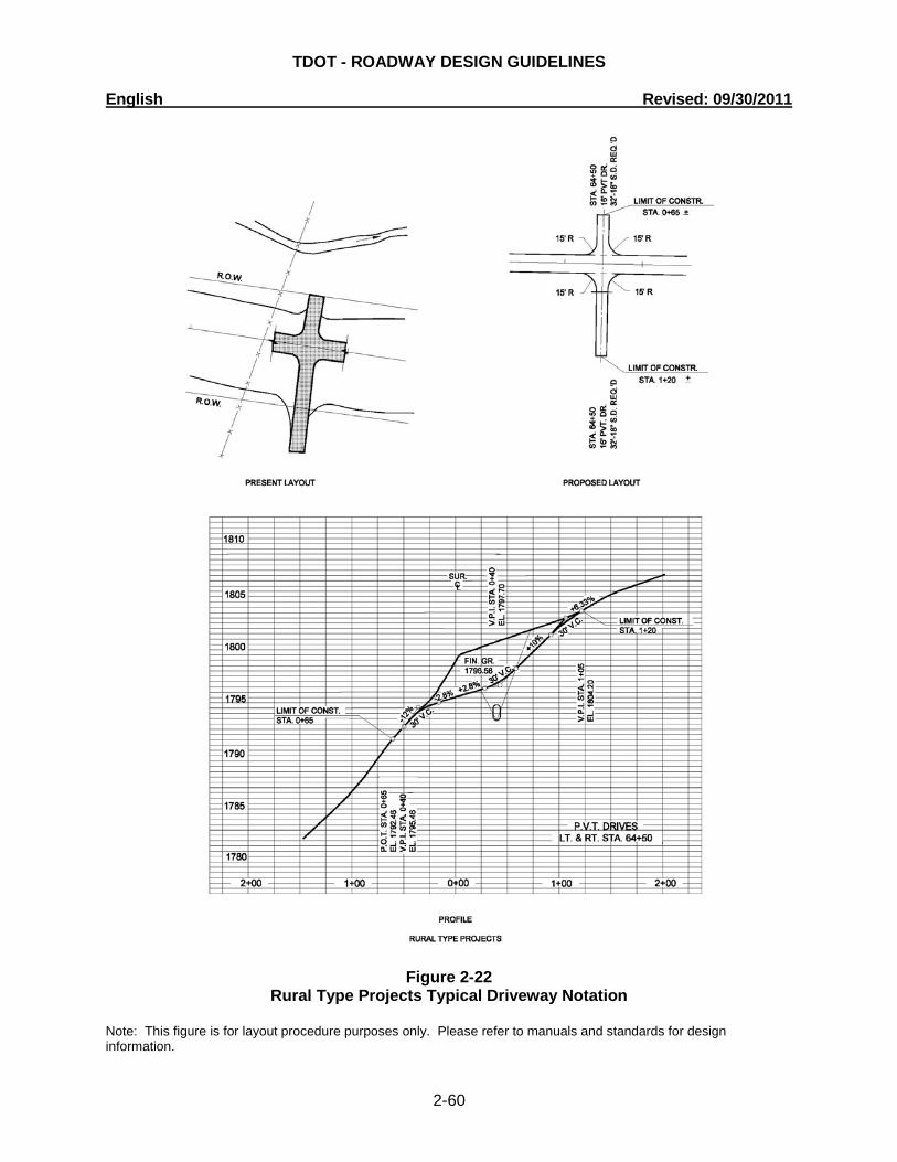
TDOT - ROADWAY DESIGN GUIDELINES English Revised: 09/30/2011
2-60
Figure 2-22 Rural Type Projects Typical Driveway Notation
Note: This figure is for layout procedure purposes only. Please refer to manuals and standards for design information.
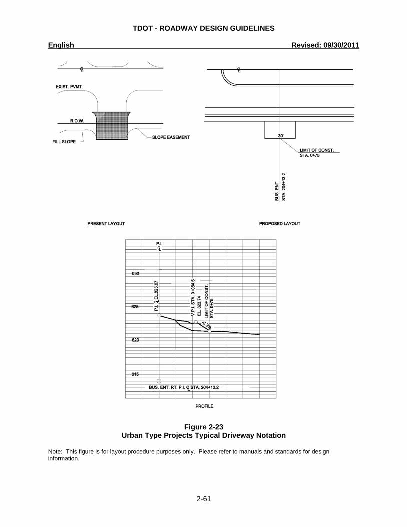
TDOT - ROADWAY DESIGN GUIDELINES English Revised: 09/30/2011
2-61
Figure 2-23 Urban Type Projects Typical Driveway Notation
Note: This figure is for layout procedure purposes only. Please refer to manuals and standards for design information.
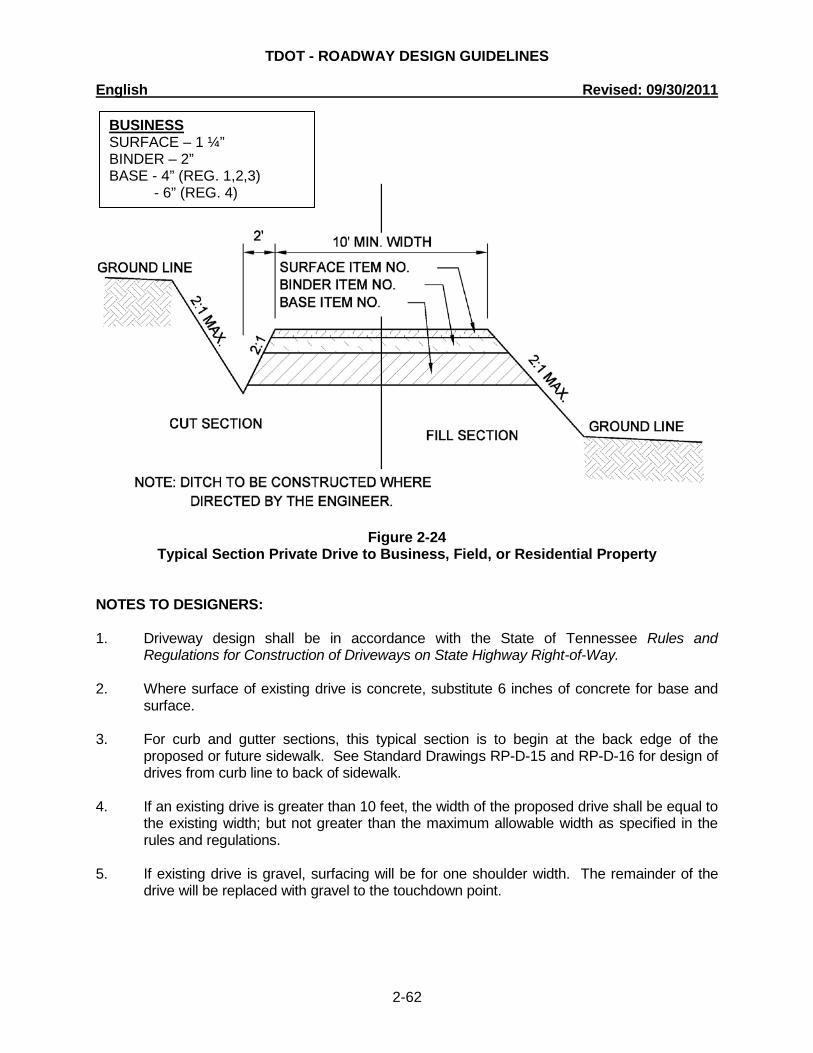
TDOT - ROADWAY DESIGN GUIDELINES English Revised: 09/30/2011
2-62
Figure 2-24 Typical Section Private Drive to Business, Field, or Residential Property
NOTES TO DESIGNERS: 1. Driveway design shall be in accordance with the State of Tennessee Rules and
Regulations for Construction of Driveways on State Highway Right-of-Way. 2. Where surface of existing drive is concrete, substitute 6 inches of concrete for base and
surface. 3. For curb and gutter sections, this typical section is to begin at the back edge of the
proposed or future sidewalk. See Standard Drawings RP-D-15 and RP-D-16 for design of drives from curb line to back of sidewalk.
4. If an existing drive is greater than 10 feet, the width of the proposed drive shall be equal to
the existing width; but not greater than the maximum allowable width as specified in the rules and regulations.
5. If existing drive is gravel, surfacing will be for one shoulder width. The remainder of the
drive will be replaced with gravel to the touchdown point.
BUSINESS SURFACE – 1 ¼” BINDER – 2” BASE - 4” (REG. 1,2,3) - 6” (REG. 4)
TDOT - ROADWAY DESIGN GUIDELINES English Revised: 09/30/2011
2-63
2-300.10 GUIDELINES FOR CONSTRUCTION AND RESURFACING OF PUBLIC ROAD INTERSECTIONS AND DRIVEWAYS ON HIGHWAY PROJECTS
I. GENERAL
This is a general guide for designers and departmental staff to use in developing project plans. Driveway installations on highway rights-of-way by individuals, firms, and corporations for each property are governed by TCA §54-5-301 through 54-5-303 and Rules and Regulations for Construction of Driveways on State Highway Right-of-Way (Rev. Jan. 1, 1967). Locations of driveways on new construction are also guided by the above Rules. In an effort to provide statewide uniformity, all future resurfacing, reconstruction and projects on new location shall include public road intersection and driveway construction in accordance with the provisions of this Guideline.
II. DEFINITION OF TERMS
Paved Shoulder Width - The width of the shoulder paved as part of the project. Paver Width - The width of asphalt paving machine used on mainline paving with maximum width not to exceed 12 feet or to extend beyond right-of-way limit. Normal Right-of-Way - An imaginary line which, when projected through a public road intersection, would enclose the normal slopes of the highway.
III. RESURFACING
A. Where directed by the TDOT Engineer, the Contractor shall be required to
shape public side roads, business entrances, and private drives, as well as clean existing drains before placing materials. All costs are to be included in the price bid for other items of construction.
B. Resurfacing projects on roadways with shoulders and ditches (no curb or
gutter):
1. All public side roads shall be paved one paver width through the intersection as a minimum. A satisfactory transition from the new pavement to the existing grade of the intersecting public road or business entrance shall be provided. Should the pavement of the intersecting public road be distressed, the resurfacing width may be increased to the normal right-of-way line.
2. Private driveways, field entrances, and business entrances will be
resurfaced a paver width (lane width) as a minimum. A pavement taper to transition the new pavement shall be required, it shall be based on an additional 1 foot of width per inch depth of pavement. If the shoulder is narrow enough that the sum of the shoulder and the transition are less than a paver width (lane width), the transition shall occur within the paver width. If the sum of the shoulder and the transition is greater than a paver width (lane width), the transition shall occur outside of the paver width.
TDOT - ROADWAY DESIGN GUIDELINES English Revised: 09/30/2011
2-64
C. Resurfacing projects on roadway with urban curb and gutters
1. Public road intersections shall be resurfaced to the end of the radius. A satisfactory transition from the new pavement to the existing grade of the intersecting public road shall be provided.
2. Residential driveways and business entrances shall have a
minimum width of material not less than one foot used in the transition to feather the pavement edge.
D. In all cases, the length of the pavement transition, the thickness and width
of the resurfacing and any additional pavement materials shall be as directed by the TDOT Engineer.
IV. NEW OR RECONSTRUCTION
A. Facilities with Full Access Control
1. Full access control will be maintained for the entire designated
project limits.
B. Facilities with Limited Access Control
1. Access will be allowed at public roads and streets only. No driveways will be permitted access to the mainline project.
C. Facilities with Partial Access Control - driveways permitted:
1. Fence Opening:
One 50-foot opening in the control access fence will be provided per tract remainder, unless access is provided from an intersecting road or based on physical conditions and/or conflicts with other design considerations, which prevent an access opening.
2. Existing Driveways:
Existing paved driveway per tract remainder will be replaced in-kind to a touchdown point.
Where the existing driveway is unpaved and the proposed driveway exceeds 7 percent in grade, each proposed driveway will be paved to a touchdown point or until the grade is less than 7 percent.
Where the existing driveway is unpaved and the proposed driveway is less than 7 percent in grade, each proposed driveway will be paved a shoulder width from the edge of pavement and the remainder of that driveway replaced in-kind to a touchdown point.
3. Requirements for field entrances and/or other driveways:
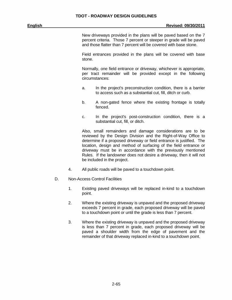
TDOT - ROADWAY DESIGN GUIDELINES English Revised: 09/30/2011
2-65
New driveways provided in the plans will be paved based on the 7 percent criteria. Those 7 percent or steeper in grade will be paved and those flatter than 7 percent will be covered with base stone.
Field entrances provided in the plans will be covered with base stone.
Normally, one field entrance or driveway, whichever is appropriate, per tract remainder will be provided except in the following circumstances:
a. In the project's preconstruction condition, there is a barrier
to access such as a substantial cut, fill, ditch or curb. b. A non-gated fence where the existing frontage is totally
fenced. c. In the project's post-construction condition, there is a
substantial cut, fill, or ditch.
Also, small remainders and damage considerations are to be reviewed by the Design Division and the Right-of-Way Office to determine if a proposed driveway or field entrance is justified. The location, design and method of surfacing of the field entrance or driveway must be in accordance with the previously mentioned Rules. If the landowner does not desire a driveway, then it will not be included in the project.
4. All public roads will be paved to a touchdown point.
D. Non-Access Control Facilities
1. Existing paved driveways will be replaced in-kind to a touchdown
point. 2. Where the existing driveway is unpaved and the proposed driveway
exceeds 7 percent in grade, each proposed driveway will be paved to a touchdown point or until the grade is less than 7 percent.
3. Where the existing driveway is unpaved and the proposed driveway
is less than 7 percent in grade, each proposed driveway will be paved a shoulder width from the edge of pavement and the remainder of that driveway replaced in-kind to a touchdown point.
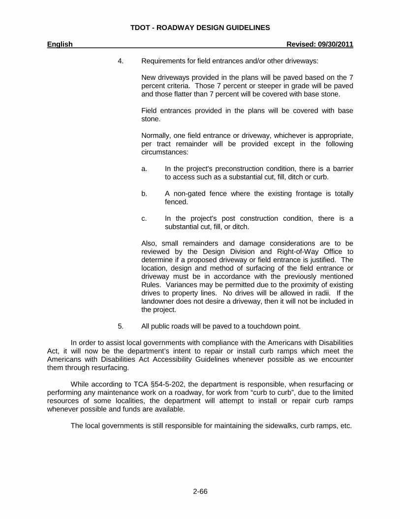
TDOT - ROADWAY DESIGN GUIDELINES English Revised: 09/30/2011
2-66
4. Requirements for field entrances and/or other driveways:
New driveways provided in the plans will be paved based on the 7 percent criteria. Those 7 percent or steeper in grade will be paved and those flatter than 7 percent will be covered with base stone.
Field entrances provided in the plans will be covered with base stone.
Normally, one field entrance or driveway, whichever is appropriate, per tract remainder will be provided except in the following circumstances:
a. In the project's preconstruction condition, there is a barrier
to access such as a substantial cut, fill, ditch or curb. b. A non-gated fence where the existing frontage is totally
fenced. c. In the project's post construction condition, there is a
substantial cut, fill, or ditch.
Also, small remainders and damage considerations are to be reviewed by the Design Division and Right-of-Way Office to determine if a proposed driveway or field entrance is justified. The location, design and method of surfacing of the field entrance or driveway must be in accordance with the previously mentioned Rules. Variances may be permitted due to the proximity of existing drives to property lines. No drives will be allowed in radii. If the landowner does not desire a driveway, then it will not be included in the project.
5. All public roads will be paved to a touchdown point.
In order to assist local governments with compliance with the Americans with Disabilities
Act, it will now be the department’s intent to repair or install curb ramps which meet the Americans with Disabilities Act Accessibility Guidelines whenever possible as we encounter them through resurfacing.
While according to TCA §54-5-202, the department is responsible, when resurfacing or
performing any maintenance work on a roadway, for work from “curb to curb”, due to the limited resources of some localities, the department will attempt to install or repair curb ramps whenever possible and funds are available.
The local governments is still responsible for maintaining the sidewalks, curb ramps, etc.

TDOT - ROADWAY DESIGN GUIDELINES English Revised: 09/30/2011
2-67
2-310.00 ACCESS CONTROL - CROSSROADS AT INTERCHANGES
The extent of the access control for rural highways will be 300 feet from the ramp terminal, treating each side of the crossroad independently. Thus, where the interchange ramp terminals at the crossroad are not opposite each other, the limits of access control will not be opposite; each being 300 feet from the ramp terminal which governs. For urban highways, the extent of access control shall be 100 feet. 2-315.00 TRAFFIC SIGNAL AND LIGHTING DESIGNS FOR ROADWAY PROJECTS (See 3-140.00, 3-400.05, 3-400.15, 4-145.00, 4-714.00 and 4-730.10) The following steps are to be followed in order to assist the ITS, Traffic, and Standards Office in providing signalization and lighting designs in a timely manner as well as to allow the ITS, Traffic, and Standards Office to schedule its work efficiently.
A. When the Transportation Planning Report (TPR) indicates that signalization and/or lighting is required on a project, or if signalization and/or lighting is not included in the TPR, but there is suspicion that signals and/or lighting may be involved in a project, the ITS, Traffic, and Standards Office shall receive plans six weeks prior to the Preliminary Field Review in order to schedule this work with other duties. Designers are reminded that all available design traffic data (including ADT’s, DHV’s, Design Speed, and traffic turning movements at all intersections) shall be included in the preliminary plans. The ITS, Traffic, and Standards Office will respond to the designer indicating where signalization is warranted, or if no signalization will be involved, give any comments pertaining to geometric improvements that will provide better operations characteristics.
B. For Right-of-Way or Utility Plans, the designer shall submit electronic files through
disks or E-mail no later than four weeks prior to the Right-of-Way Field Review or Utility Plans Submittal. These electronic files shall adhere to the following stipulations:
1. These files shall consist of a Alignment File, a Survey File, and a Proposed
Final (merged) .tin and .gpk files.
2. No other files shall be submitted unless specifically requested by the ITS, Traffic, and Standards Office.
3. All files shall follow the naming convention set forth in the Survey and
Design Computer-Aided Drafting Standards.
4. The working units of all these files shall coincide with the working units set forth in the Survey and Design Computer-Aided Drafting Standards.
5. All files shall be in DGN format.
The ITS, Traffic, and Standards Office, will provide support pole and lighting pole
locations and related information for the Right-of-Way Plans (or Utility Plans). C. For Construction Plans the designer shall resubmit the Work File through disks or
E-mail no later than four weeks prior to the Construction Field Review to ensure

TDOT - ROADWAY DESIGN GUIDELINES English Revised: 09/30/2011
2-68
that the latest changes will be reflected on the signal and/or lighting layout. The previously stated stipulations shall apply to the submittal of the new Work File to be used for the Construction Plans.
D. The ITS, Traffic, and Standards Office, will then complete and submit final signal
and/or lighting design, quantities, standard drawings, and applicable notes for Construction Plans assembly.
2-315.05 ROADWAY LIGHTING INFORMATION FOR RIGHT-OF-WAY / UTILITIES (See 3-140.00, 3-400.05, 3-400.15, 4-145.00 and 4-714.00) When the Transportation Planning Report (TPR) indicates that lighting is required on a project, the designer shall furnish the ITS, Traffic, and Standards Office, with a set of prints and request a pole location layout. These prints shall be furnished by the designer at the "preliminary plans" stage of project development to ensure that the utility requirements will be shown on the plans for the Right-of-Way Field Review. If there is no right-of-way acquisition required on the plans, but lighting is required, the designer shall furnish the ITS, Traffic, and Standards Office with a set of prints of the plans as soon as the present and proposed layout sheets are drawn and request the light pole locations. This is to ensure that the utility requirements will be shown on the plans for Utility Plans submittal. 2-320.00 EASEMENTS - GENERAL (See 3-300.05) The Right-of-Way Acquisition Table shall have three columns for easements. The first column shall be for Permanent Drainage Easements, the second column shall be for Slope Easements, and the third column shall be for Construction Easements. Figure 2-25 is a model R.O.W. Acquisition Table. Figure 2-26 demonstrates how to show various easements on the plans. 2-320.05 PERMANENT DRAINAGE EASEMENT ON PLANS (See 2-200.00) Slope and Construction Easements shall not overlap Permanent Drainage Easements. The Permanent Drainage Easement shall extend from the Right-of-Way and have precedence over other easements. Permanent drainage easements may be appropriate for channel changes and realignments or ditches where no ditch existed before the proposed project. Permanent drainage easements will be required for ponding occurring outside the right-of-way, as discussed elsewhere in this document. On urban curb and gutter roadway sections, when catch basins must be located outside the right-of-way line to eliminate ponding or when a cross drain pipe and headwalls are installed outside the right-of-way line, permanent drainage easements shall be set up for these structures. Good engineering judgment must be exercised regarding the amount of drainage easement taken.

TDOT - ROADWAY DESIGN GUIDELINES English Revised: 09/30/2011
2-69
Riprap, for the protection of proposed structures that are outside of the right-of-way, shall be located within a permanent drainage easement.
There may be isolated instances where permanent drainage easements may be required for other reasons. In these instances, the Right-of-Way Division's concurrence shall be required.
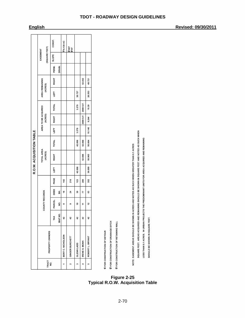
TDOT - ROADWAY DESIGN GUIDELINES English Revised: 09/30/2011
2-70
Figure 2-25
Typical R.O.W. Acquisition Table
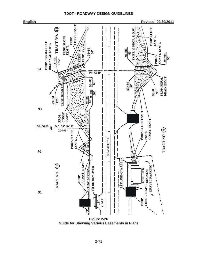
TDOT - ROADWAY DESIGN GUIDELINES English Revised: 09/30/2011
2-71
Figure 2-26 Guide for Showing Various Easements in Plans
94
93
92
91
204.01’92+56.86
93+6
012
5’
68.01’
68.01’125’
93+9
0
PROP. 36”CMP
94+1
060
’
36” CMP
60’
94+0
460
’93
+84
95’
93+8
4
95’
94+0
4
35’
35’
10’
43.1
6’
18”
50’
60’
93+8
093
+00
60’
93+0
0
TDOT - ROADWAY DESIGN GUIDELINES English Revised: 09/30/2011
2-72
2-320.10 SLOPE EASEMENTS The Slope Easement column shall contain only that area outside the right-of-way, required for slopes. 2-320.15 CONSTRUCTION EASEMENTS All easement areas that do not go in the Drainage Easement or Slope Easement columns, such as detours, some drainage ditches and channel improvements (such as widening or bank stabilization with riprap), locations where a ditch or channel already exists, sediment basins and other erosion prevention and sediment control areas, working room for retaining walls and permanent easement on railroad right-of-way, shall be placed in the construction easement column and footnoted as appropriate. A 10-foot construction easement, for working outside slope easements, is to be shown on the plans sheet. This construction easement may be reduced or eliminated as necessary to avoid trees, buildings, etc. It may be necessary to increase the easement size to allow for pollution control structures and high fills. 2-320.20 PRELIMINARY RIGHT-OF-WAY ESTIMATE FROM PRELIMINARY FIELD
REVIEW PLANS
Design will provide preliminary acquisition areas and slope easement areas to the Right-of-Way Division so that a preliminary right-of-way estimate can be developed. Design managers will be responsible for furnishing a copy of the R.O.W. Acquisition Excel File with acquisition areas and slope easement areas prior to scheduling the preliminary field review.
Designers shall calculate preliminary areas using the following procedure: 1. Calculate acquisition areas and slope easements with MicroStation’s Measure
Area tool using the Points or Flood methods. It is not necessary to store areas in the GEOPAK GPK file nor should time be spent defining shape elements in MicroStation for area calculations.
2. In the R.O.W. Acquisition Excel File provided by Survey and includes owner and tract information, enter the calculated square foot areas on the “DES IN” worksheet.
3. Make a copy of the Excel file and rename it using the State Route Number, County and Pin Number followed by the extension .xls. Example: SR1Knox405132.00.xls
4. Consultants shall provide the Excel file to the Design Manager. For projects developed in-house, the designer should submit the excel file to the e-mail address listed below with a copy of the e-mail being sent to the Design Manager.
5. Submit the Excel file via email as an attachment to [email protected]. Subject line for email should be Preliminary Areas-State Route #, County, PIN. Example: Preliminary Areas, SR 1, Knox County, PIN 405132.00. A copy of the e-mail shall be placed in the project folder to document the submittal of preliminary acquisition and slope easement areas.
2-325.00 RAILROADS (See 1-210.00, 1-210.05 and 1-210.10) 2-330.00 FIELD REVIEW PROCEDURES (See 1-120.00)