tdma scheduling with optimized energy efficiency and minimum delay in clustered w
TRANSCRIPT

5/14/2018 TDMA Scheduling With Optimized Energy Efficiency and Minimum Delay in Clustered W ...
http://slidepdf.com/reader/full/tdma-scheduling-with-optimized-energy-efficiency-and-minimum-delay
TDMA Scheduling with Optimized EnergyEfficiency and Minimum Delay in Clustered
Wireless Sensor NetworksLiqi Shi, Student Member , IEEE , and Abraham O. Fapojuwo, Senior Member , IEEE
Abstract—In this paper, we propose a solution to the scheduling problem in clustered wireless sensor networks (WSNs). The
objective is to provide network-wide optimized time division multiple access (TDMA) schedules that can achieve high power efficiency,
zero conflict, and reduced end-to-end delay. To achieve this objective, we first build a nonlinear cross-layer optimization model
involving the network, medium access control (MAC), and physical layers, which aims at reducing the overall energy consumption. We
solve this problem by transforming the model into two simpler subproblems. Based on the network-wide flow distribution calculated
from the optimization model and transmission power on every link, we then propose an algorithm for deriving the TDMA schedules,
utilizing the slot reuse concept to achieve minimum TDMA frame length. Numerical results reveal that our proposed solution reduces
the energy consumption and delay significantly, while simultaneously satisfying a specified reliability objective.
Index Terms—Wireless sensor networks, cross-layer optimization, power efficiency, TDMA scheduling, slot reuse.
Ç
1 INTRODUCTION
SCHEDULING of medium access plays an important role inthe performance of wireless sensor networks (WSNs). In
the literature, time division multiple access (TDMA) andcarrier sensing multiple access (CSMA) are two majormedium access approaches in WSNs. This work will onlyfocus on the TDMA approach because the scenariospecification of our research is a static network in whichTDMA is said to be more effective than CSMA, especiallyunder medium to high traffic load [1].
In this paper, we aim at deriving TDMA schedules withoptimized power consumption and minimum latency inclustered WSNs. Energy efficiency is a major concern inWSNs, since the batteries are often impossible to bereplaced or recharged in many cases [2]. In TDMA, a nodecan be active only if it is scheduled to send or receive data,which give it advantages in power efficiency. In theliterature, the medium access control (MAC) protocol of many WSN and ad hoc network proposals is TDMA based,e.g., [3], [4], [5]. Recently, cross-layer design is furtheradopted to achieve least energy consumption in TDMA- based WSNs, as summarized in [6].
In addition to energy efficiency, quality of service
(QoS) metrics such as end-to-end delay needs to be takeninto account in some applications or under certainscenarios, for instance, delivering real-time data in radioharsh environments.
To achieve the paper’s objective, we propose a two-stepapproach to derive TDMA schedules supporting both high
energy efficiency and minimum delay in WSNs. In the firststep, we formulate the problem via cross-layer optimiza-tion, aiming at deriving the most energy-efficient flows onevery link. Based on the calculated per-link flows, in thesecond step, we propose an algorithm to obtain a TDMAschedule with the least frame length. From the analysispresented in Section 5, the least frame length guaranteesminimum delay for the derived TDMA schedules.
We consider the application of the proposed two-step
approach in clustered WSNs. It is widely known thatclustering technique can provide scalability for large-sizeWSNs, since most of the operations can be accomplished atcluster heads (CHs) and gateways (if present), whosenumber is much less than the number of sensing nodes.Instead of only addressing intracluster slot assignment, as ismostly done in the literature (e.g., BMA [7]), we focus on themore challenging intercluster slot assignment.
The main contributions of this paper are twofold. First,we build a cross-layer nonlinear optimization model toachieve energy efficiency with specified link reliability and bandwidth constraints. Instead of solving this nonlinearoptimization problem directly by heuristic algorithms, we
transform the problem into two simpler subproblems at lesscomplexity, which facilitates the application of our ap-proach in large-size WSNs. Second, we propose a schedul-ing algorithm for slot assignment in clustered WSNs. Thisscheduling algorithm incorporates the slot reuse concept(from cellular networks) in calculating the schedules basedon the optimal flows derived from the proposed optimiza-tion model. We show that the slot reuse concept signifi-cantly reduces the end-to-end latency without a penalty inthe energy efficiency. The above two contributions distin-guish our work from previous related works in theliterature, for example, [8], [9].
The paper is organized as follows: Section 2 provides an
overview of the related work in the literature. In Section 3,
IEEE TRANSACTIONS ON MOBILE COMPUTING, VOL. 9, NO. 7, JULY 2010 927
. The authors are with the Department of Electrical and ComputerEngineering, The University of Calgary, 2500 University Drive N.W.,Calgary, AB T2N 1N4, Canada. E-mail: {lishi, fapojuwo}@ucalgary.ca.
Manuscript received 29 Aug. 2008; revised 4 June 2009; accepted 12 Oct.2009; published online 9 Mar. 2010.For information on obtaining reprints of this article, please send e-mail to:[email protected], and reference IEEECS Log Number TMC-2008-08-0348.
Digital Object Identifier no. 10.1109/TMC.2010.42.1536-1233/10/$26.00 ß 2010 IEEE Published by the IEEE CS, CASS, ComSoc, IES, & SPS
Authorized licensed use limited to: VELLORE INSTITUTE OF TECHNOLOGY. Downloaded on July 26,2010 at 10:10:33 UTC from IEEE Xplore. Restrictions apply.

5/14/2018 TDMA Scheduling With Optimized Energy Efficiency and Minimum Delay in Clustered W ...
http://slidepdf.com/reader/full/tdma-scheduling-with-optimized-energy-efficiency-and-minimum-delay
we describe the system model. Section 4 presents theproposed cross-layer nonlinear optimization model toachieve the energy efficiency. This is followed by thedescription of the proposed scheduling algorithm, whichforms the topic of Section 5. Numerical results are presentedand discussed in Section 6. We conclude the paper inSection 7.
2 RELATED WORK
Earlier works on TDMA scheduling for WSNs mainly focuson obtaining the shortest schedules [10], [11] or distributedimplementation [3], [4], [5], [10]. In [10], nonconflictedschedules are obtained first, and a following algorithm thengoes through all nodes and slots, in turn, to producemaximal broadcasting sets, thus reducing the schedulelength. The authors of [11] further take into account thenumber of packets being sent at every node, and providethe shortest schedules by eliminating the nodes withoutpackets to send at each loop of the proposed algorithm.
Both of the algorithms in [10] and [11] need global topologyinformation, which may not be scalable for very large-sizenetworks. To overcome the difficulty of obtaining globaltopology information in very large-size networks, manydistributed slot assignment schemes have been proposed,such as DRAND [3], PACT [4], TRAMA [5], and the depthfirst search (DFS) scheme used in [10]. These approachesobtain local topology and interference information at eachnode, and compose schedules by exchanging messages between local nodes within a certain range (i.e., theinterference range). Compared to the approaches demand-ing global topology information, distributed scheduling ismore flexible, but at a cost of increased schedule length.
The focus of the works in [3], [4], [5], [10], [11] is at theMAC layer. Working on a single layer only may lead toinefficiency in utilizing the network resources. Recently,cross-layer design approach is combined with TDMAscheduling in order to obtain prolonged network lifetime.In [12], joint routing, link scheduling, and power control areconsidered to support high data rate for broadband wirelessmultihop networks. A framework for cross-layer designtoward energy-efficient communication is presented in [13].The authors address joint link scheduling and powercontrol with the objective of energy efficiency subject toQoS guarantees in terms of bandwidth and bit error rate(BER). A heuristic solution is proposed.
Interference-free TDMA schedules are calculated in [8]
for a small-scale network by joint optimization of thephysical, MAC, and network layers. The authors use convexoptimization to solve the cross-layer-based network lifetimeoptimization problem, employing the interior point method[14]. A single frame without slot reuse for the wholenetwork guarantees no interference. However, this alsoleads to significant end-to-end delay, which makes thisapproach unsuitable for large-size WSNs. In [9], the authorsconsider both joint layer optimization and slot reuse toderive energy-efficient schedules. A convex cross-layeroptimization model is proposed and solved iteratively tomaximize the network lifetime. The link schedules evolve ateach iteration until a specific energy consumption goal is
reached or no more optimal solution can be found.
For consistency with previous works, such as [8], [9], [12],[13], the energy efficiency formulation presented in thispaper is also based on cross-layer design, and includes theQoS constraints of packet loss rate (PLR) [15], [16]. Our workalso calculates interference-free TDMA schedules by incor-porating the slot reuse concept, similar to what was done in[9]. However, compared to these previous works, our work
exhibits three differences: First, the proposed framework(i.e., cross-layer-based energy optimization model andscheduling algorithm) achieves energy efficiency for aspecified PLR objective while minimizing the delay. Forexample, Cui et al. [8], [9] have focused on lifetimemaximization, Kwon et al. [15] considered only the end-to-end PLR, and Yuan et al. [16] included both PLR and delayobjectives, treated in the context of a specific virtual multipleinput multiple output cooperative communication. Second,we incorporate the slot reuse concept for the purpose of reducing the delay of the optimal flows obtained from thecross-layer optimization model. Our intent of incorporatingtheslot reuse concept is, therefore, quite different from its use
in [9] whose goal is that of maximizing the network’slifetime. Third, the proposed scheduling heuristic is flexible,applicable to both clustered and nonclustered WSN archi-tectures, unlike the approaches in previous works that arespecific to a given network architecture.
3 SYSTEM MODEL
In this section, we present the wireless sensor networkarchitecture and models of the physical, MAC, and networklayers. These models serve as input to the cross-layeroptimization model.
3.1 Network Architecture
The nodes in the network are divided into multipleclusters, each comprising a CH and cluster members thatcommunicate via one hop to the CH. For example, theclustering scheme proposed in [17] can be used to formclusters, as development of clustering algorithms is outsidethe scope of this paper. However, the solution presented inthis paper applies to any other clustering schemes. Usingthe clustering scheme presented in [17], gateways areselected to connect neighboring CHs. A gateway is acluster member belonging to the cluster represented by oneof the CHs it connects. As seen from Fig. 1a, note that wedo not constrain the transmission range of CHs andgateways within one hop though. Only the intracluster
communication (i.e., communication from cluster membersto the CH) is restricted to one hop. To simplify thepresentation of the network model (Fig. 1a), the sensornodes inside each cluster are not shown explicitly. Instead,we represent the total traffic generated by all the activemembers of a cluster and sent to the CH by a “virtual”link, as illustrated in Fig. 1b.
We assume that the operation of the network is dividedinto rounds, each composed of an initialization phasefollowed by a data relay phase, as shown in Fig. 2. A newround is initiated when a WSN is deployed or the availablepower of a CH or gateway reaches a specified threshold, orafter a fixed time interval. A contention-based protocol,
such as CSMA, is used in the initialization phase of each
928 IEEE TRANSACTIONS ON MOBILE COMPUTING, VOL. 9, NO. 7, JULY 2010
Authorized licensed use limited to: VELLORE INSTITUTE OF TECHNOLOGY. Downloaded on July 26,2010 at 10:10:33 UTC from IEEE Xplore. Restrictions apply.

5/14/2018 TDMA Scheduling With Optimized Energy Efficiency and Minimum Delay in Clustered W ...
http://slidepdf.com/reader/full/tdma-scheduling-with-optimized-energy-efficiency-and-minimum-delay
round to form clusters, and allows the only sink node in thenetwork to obtain the topology of the backbone networkcomposed of CHs and gateways. The sink then calculatesthe optimized schedule (i.e., number of slots required oneach link and the ID number of the slot in a TDMA frame to be assigned to each required slot) and informs all nodes(e.g., broadcasts the schedule directly to all nodes), afterwhich the network enters the data relay phase. The durationof the initialization phase, t1, is far less than that of the datarelay phase, t2, so that the energy consumption during theinitialization phase can be neglected. This operation roundrepeats until a certain percentage of nodes run out of energy
or their energy is below a certain threshold. In this paper,we only focus on the data relay phase and investigateTDMA scheduling during this phase, under optimizedpower consumption and minimum latency.
A graph G ¼ ðV ; LÞ is used to denote the backbonenetwork (composed of CHs and gateways, including thesink), where V is the set of nodes and L the set of links.Henceforth, in this paper, the term network refers to the backbone network with node set of V and link set of L. Thetotal number of nodes in the network is N ¼ jV j, inwhichthesink is taken as node #1, without loss of generality. If amaximum transmission power is specified, we use G ¼ðV ; L0Þ instead of G ¼ ðV ; LÞ, where L0,asubsetof L,istheset
of links that can be formed according to the specifiedmaximum transmission power P tx;max. A link ði; jÞ is validonly if ði; jÞ 2 L0. The links areunidirectional so that link ði; jÞand link ð j;iÞ are two different links. We assume that thesensor nodes in the network are stationary, for simplicity.
3.2 Physical Layer
To some extent, the physical layer model determines theaccuracy of the cross-layer optimization model. A realisticphysical layer model considers the propagation model,modulation, encoding, demodulation, and decoding tech-niques, thus linking major parameters such as power, signalto noise ratio (SNR), and bit error rate together. Examples of
such a physical layer model can be found in [18].
In this paper, we use the following path loss model [19]:
P lðd Þ ¼ P lðd 0Þ þ 10 log 10ðd=d 0Þ; ð1Þ
where d is the distance between the transmitter and receiver,d 0 is the reference distance, and is the path loss exponent.The parameter can be obtained empirically from propaga-tion measurements. By setting the distance between nodesassigned the same slot large enough such that theinterference is far less than thermal noise, the interference between these nodes is considered to be negligible. The biterror rate P e can then be expressed as a function of SNR,
given the modulation-demodulation (MODEM) scheme. Inthis paper, we suppose that Mica2 motes [20] are used. Forthe noncoherent FSK MODEM scheme used in Mica2 motes,the bit error rate is given by [21]:
P e ¼1
2e
ÀSNR2
B N R ; ð2Þ
where R is the data rate in bits per second (bps) and B N isthe noise bandwidth. The SNR at a receiver which is locatedat distance d from the transmitter can be expressed in anaverage manner, given by
SNRðd ÞdB ¼ P tx dBm À P lðd ÞdB À P n dBm; ð3Þ
in which the parameters on the right-hand side are,respectively, the transmission power, average path loss atdistance d , and the noise floor, all expressed in decibel units.
Suppose the length of a packet is F bytes, the encodingrate is , then the packet loss rate p on each link, defined asthe probability that at least one transmitted bit in a packet iscorrupted, is given by
p ¼ 1 À ð1 À P eÞ8F : ð4Þ
After linking all these parameters together, we still needto build an energy consumption model. The major energyconsumption is spent on CPU, radio, and sensors, etc. It is
hard to estimate the CPU cycles in analysis, but in mostcases, it can be neglected [22]. The energy consumed bysensing task is determined by the environments beingmonitored and the sensing scheme (e.g., only somedesignated sensors are active to achieve a certain coveragereliability objective). Given the environments being mon-itored and the predetermined monitoring scheme, over agiven period, we can assume that the sensing energyconsumption is fixed or can be estimated, and this energyconsumption can then be deducted from the total availableenergy in the given period. Thus, we can now focus onlyon the radio power, which can be adjusted to attain lessenergy consumption. The average transmission energy
consumption by node x, in transmitting a data bit to
SHI AND FAPOJUWO: TDMA SCHEDULING WITH OPTIMIZED ENERGY EFFICIENCY AND MINIMUM DELAY IN CLUSTERED WIRELESS... 929
Fig. 2. Operation rounds.
Fig. 1. Network model.
Authorized licensed use limited to: VELLORE INSTITUTE OF TECHNOLOGY. Downloaded on July 26,2010 at 10:10:33 UTC from IEEE Xplore. Restrictions apply.

5/14/2018 TDMA Scheduling With Optimized Energy Efficiency and Minimum Delay in Clustered W ...
http://slidepdf.com/reader/full/tdma-scheduling-with-optimized-energy-efficiency-and-minimum-delay
node y with transmit power P tx;xy ¼ P cir;tx þ P txðd xyÞ, can be expressed as
E ðP tx;xyÞ ¼1
RðP cir;tx þ P txðd xyÞÞ; ð5Þ
where P cir;tx is the power consumed by the transmittercircuits (excluding the power amplifier circuit), which is a
constant. The term P txðd xyÞ is the power consumed by thepower amplifier circuit at node x separated from node y bydistance d xy, and is calculated using (3) (expressed in linearunits) in concert with (1) and (2). Clearly, P tx;xy is variabledepending on the transmission distance d xy and the packetloss rate objective. For a given receiver circuit, the per bitaverage receiving energy consumption at receive power P rx
is fixed, calculated by E ðP rxÞ ¼ P rx=R, where P rx is set toP cir;rx, the power consumed by the receiver circuits, whichis also a constant.
3.3 MAC Layer
As stated in Section 1, the TDMA scheme is the MAC layerprotocol employed during the data relay phase. A TDMA
frame consists of a numberof slots,each with fixed length Át.We assume that NACKs and retransmissions are used at theMAC layer. However, to simplify the analysis and thescheduling algorithm, we neglect the cost of NACKs byassuming that a NACK is only generated once in each fixedfeedback period to inform the source nodes of packets notcorrectly received in the last period. By properly setting thefeedback period, energy cost of NACKs is negligiblecompared to that of data packets. Given the packet lossrate p, the per-hop average number of total transmissions fora packet to be successfully received is 1=ð1 À pÞ. Theretransmissions denote the extra cost caused by bit errors.On the other hand, increasing transmission power (whichmeans more energyconsumption perbit) can reduce bit error
rate, as seen from (2). This implies that an optimal transmis-sion power exists for a link to achieve power efficiency.
3.4 Network Layer
Multihop, multipath routing is performed at the networklayer. Every CH or gateway has knowledge of its next hopsand the proportion of data traffic to every next hop. Thesink provides this information to every CH or gateway afterderiving the optimal schedules at the end of the initializa-tion phase of each operation round.
4 CROSS-LAYER OPTIMIZATION MODEL
Based on the information provided in Section 3, a cross-
layer optimization model is formulated as follows:
minimizeXN
i¼2
XN
j¼1
E ðP tx;ijÞ1
1 À pijf ij þ
XN
i¼2
XN
j¼2
E ðP rxÞ1
1 À pijf ij
þXN
i¼2
iE ðP rxÞ þXN
i¼2
XN SN;i
k¼1
½E sens;k þ E ðP tx;kiÞði=N SN;iÞ
!;
ði; jÞ 2 L0; i 6¼ j
ð6aÞ
s:t: f ij ! 0; i 2 ½2; N ; j 2 ½1; N ; i 6¼ j; ð6bÞ
f ij ¼ 0 iff ði; jÞ 62 L0or i ¼ j; ð6cÞ
XN
j¼1;j6¼i
ðf ij À f jiÞ ¼ i=C i; i 2 ½2; N ; ð6dÞ
XN
i¼2
XN
j¼1
1
1 À pij f ij R; i 6¼ j; ð6eÞ
XN
j¼1;j6¼i
E ðP tx;ijÞf ij
1
1 À pijþ E ðP rxÞf ji
1
1 À p ji
þ iE ðP rxÞ ei i 2 ½2; N ;
ð6f Þ
where E ðP tx;ijÞ is the per bit average transmission energyconsumed at node i when transmitting to node j usingtransmission power P tx;ij, pij is the packet loss rate onlink ði; jÞ, f ij is the data flow rate (in bits per second) fromnode i to j without accounting for the retransmissions, i isthe new generated traffic (in bits per second), C i is the traffic
aggregation factor at node i if node i is a source CH, E sens;k isthe sensing energy expended by each sensor node k in aclusterto capture and process thedata, N SN;i is the numberof active sensor nodes in cluster i, and ei is the allowedmaximum consumed energy per unit time at node i (e.g.,ei ¼ ei;avail=T , where ei;avail is the initial available energy inmillijoule (mJ ) at node i and T is a fixed lifetime in seconds).
The objective function in (6a) gives the total consumede ne rg y of t he w hole net work pe r unit t ime (i .e .,mJ=sec ¼ mW ), which is composed of transmission andreceiving mode energy consumption at all backbone nodesexcluding the sink (the energy consumed at the sink isneglected because its power source is replaceable), and the
energy consumed by each active sensor node (clustermember) in sensing and transmitting the data to its CH.Note that retransmissions are ignored for the intraclustertransmissions because of the close proximity of the sensornodes in a cluster to their cluster head, this is not the case forintercluster communication where the intercluster distance istypically much larger than the intracluster distances.
Now, as noted in Section 3.2, for a given WSNapplication (i.e., given monitoring environment), E sens;k isconstant. Also, if we assume, for simplicity, that the sensornodes in a cluster are at approximately the same averagedistance from their CH and each generating the sameamount of traffic, then E ðP tx;kiÞði=N SN;iÞ is also a constant.From these preceding statements, we can consider the last
double summation term in (6a) as a constant. Based on theforegoing, along with the fact that the energy optimizationis being done with respect to the backbone network nodes,(6a) then reduces toXN
i¼2
XN
j¼1
E ðP tx;ijÞ1
1 À pijf ij þ
XN
i¼2
XN
j¼2
E ðP rxÞ1
1 À pijf ij
þXN
i¼2
iE ðP rxÞ
!; ði; jÞ 2 L0; i 6¼ j:
ð6a0Þ
The first two constraints (6b) and (6c) state that the flow
rate should be nonnegative and flows can only exist on
930 IEEE TRANSACTIONS ON MOBILE COMPUTING, VOL. 9, NO. 7, JULY 2010
Authorized licensed use limited to: VELLORE INSTITUTE OF TECHNOLOGY. Downloaded on July 26,2010 at 10:10:33 UTC from IEEE Xplore. Restrictions apply.

5/14/2018 TDMA Scheduling With Optimized Energy Efficiency and Minimum Delay in Clustered W ...
http://slidepdf.com/reader/full/tdma-scheduling-with-optimized-energy-efficiency-and-minimum-delay
valid links. The third constraint (6d) indicates that theoutput data rate at each node should be the sum of inputdata rate and data generation rate at that node (the data aregenerated by cluster member nodes, aggregated at thecorresponding CH, and then, relayed to the sink). Thefourth constraint (6e) is the data rate or bandwidth limit of the network, showing that the summed data rate with
retransmissions at all links should not be greater than themaximal allowed data rate. This is a conservative con-straint, since slots can be reused in our model. The fifthconstraint (6f) is the per unit time energy consumptionconstraint at every node.
The optimization model depicted by (6) is cross-layer
based because it jointly combines network layer traffic loads,
MAC layer retransmission scheme, and physical layer
modulation scheme and bit error rate together, in order to
derive appropriate transmission power P tx;ij and flow rate f ij
at every link ði; jÞ, ði; jÞ 2 L0; i 6¼ j, to achieve network-wide
optimal power efficiency. Applying (2)-(5), this model is
obviously nonlinear due to the terms E ðP tx;ijÞ 11À pij
and
E ðP rxÞ1
1À pij ; ði; jÞ 2 L0
; i 6¼ j, which are, respectively, thetransmit and receive energy consumed in relaying a bit from
node i to j. Solving this nonlinear optimization problem
directly is a nontrivial task, so we transform the problem into
two simpler subproblems. We, therefore, propose to solve
the following subproblem #1 first.Sub_Problem #1:
min: ðE ðP tx;ijÞ þ E ðP rxÞÞ1
1 À pijði; jÞ 2 L0
s:t: lb < P tx;ij < ub i 2 ½2; N ; j 2 ½1; N ; i 6¼ j;
ð7Þ
where lb and ub are the lower and upper bounds of thetransmission power, respectively. The purpose of subpro- blem #1 is to find the optimal transmission power onlink ði; jÞ, P opt;tx;ij, in order to consume the least energyE opt;ij;txrx for transmitting a bit from node i to j. Subpro- blem #1 is actually a simple problem of deriving theminimum value of a function. Numerical methods such asgolden section search [23] can be adopted to solve thisproblem. The solution to (7) then serves as input to (6).
However, before being able to use the results of (7) asinput to (6), we need to prove that the optimal transmissionpower on each link obtained from solving (6) is equivalentto that obtained from solving (7).
Lemma 1. For the optimal energy consumption model proposedin (6) on any link ði; jÞ, the model must use the optimal
transmission power of this link P opt;tx;ij to achieve network-wide optimal energy consumption.
Proof. Assume that the network-wide per bit optimal relayenergy consumption is E opt;total ¼ X þ E ij;txrx, whereE ij;txrx is the per bit relay energy consumption onlink ði; jÞ and X is the per bit relay energy consumed bythe other links in the network. Suppose the transmis-sion power at link ði; jÞ, P tx;ij, is not equal to theoptimal transmission power P opt;tx;ij of this link, we thenhave E ij;txrx > E opt;ij;txrx; thus, ðE opt;total ¼ X þ E ij;txrxÞ >ðE 0opt;total ¼ X þ E opt;ij;txrxÞ, which contradicts with thestatement that E opt;total is the network-wide per bitoptimal relay energy consumption. tu
Now, we can solve (7) and input the results to (6). Thistransforms the nonlinear optimization problem presented by(6) into a simpler linear one, which we call subproblem #2.
Sub_Problem #2:Define the parameters c1ij ¼ 1=ð1 À pijÞ and c2ij ¼
E ðP tx;ijÞ, ði; jÞ 2 L0; i 6¼ j, both are constants that can becalculated from solving (7). Subproblem #2 is then for-
mulated as
min:
XN
i¼2
XN
j¼1
c1ijc2ijf ij þXN
i¼2
XN
j¼2
c1ijE ðP rxÞf ij
þXN
i¼2
iE ðP rxÞ
!ði; jÞ 2 L0; i 6¼ j;
ð8aÞ
s:t: f ij ! 0; i 2 ½2; N ; j 2 ½1; N ; i 6¼ j; ð8bÞ
f ij ¼ 0 iff ði; jÞ 62 L0 or i ¼ j; ð8cÞ
XN
j¼1;j6¼i
ðf ij À f jiÞ ¼ i=C i; i 2 ½2; N ; ð8dÞ
XN
i¼2
XN
j¼1
c1ijf ij R; i 6¼ j; ð8eÞ
XN
j¼1;j6¼i
ðc1ijc2ijf ij þ c1 jiE ðP rxÞf jiÞ
þ iE ðP rxÞ ei i 2 ½2; N :
ð8f Þ
This linear optimization problem only has f ij as the
variables. Let L0
j j be the number of links in the backbonenetwork constrained by the maximum transmit power, thislinear optimization problem has Oð L0j jÞ variables andOðN þ L0j jÞ constraints. The problem is similar to thetraditional minimum cost flow problem [24], [25] and can be solved accordingly. Thus, we significantly reduce thecomplexity of solving the original nonlinear optimizationproblem based on Lemma 1.
Some applications may have a predetermined per-linkpacket transmission success rate (PTSR) objective (wherePTSR is the complement of PLR). In this case, we cancalculate the bit error rate and transmission power on everylink according to (2)-(4). We then derive the constants c1ij
and c2
ij, and directly input the results to (8) to solve thislinear optimization problem.
5 MINIMUM DELAY SCHEDULING ALGORITHM
Solving the optimization model in (6) gives the flowdistribution and transmission power on every link, whichachieves the energy-efficient data relay. We can, of course,calculate the TDMA slots assigned to every link accordinglywithout slot reuse. However, this results in very longTDMA frame length, and thus, unacceptable delay in large-size WSNs. Our goal then is to derive a relationship between the delay incurred by a data packet at each backbone network node (along its path to the sink) and the
TDMA frame length M so that, by reducing the frame
SHI AND FAPOJUWO: TDMA SCHEDULING WITH OPTIMIZED ENERGY EFFICIENCY AND MINIMUM DELAY IN CLUSTERED WIRELESS... 931
Authorized licensed use limited to: VELLORE INSTITUTE OF TECHNOLOGY. Downloaded on July 26,2010 at 10:10:33 UTC from IEEE Xplore. Restrictions apply.

5/14/2018 TDMA Scheduling With Optimized Energy Efficiency and Minimum Delay in Clustered W ...
http://slidepdf.com/reader/full/tdma-scheduling-with-optimized-energy-efficiency-and-minimum-delay
length through slot reuse, the delay is minimized. For thisanalysis, we determine the node delay from the instant thefirst bit arrives at the node until the time the last bit exits thenode. With the TDMA MAC adopted, the nodal delay can be approximated by the time interval between the inputtime slot where the data are read and the output time slotfrom which the data are read out. Suppose the data packet
is received at a node in slot m1, m1 2 ½1; M , and relayed outin slot m2, m2 2 ½1; M , the delay experienced by the relayeddata packet at this node is
Dðm1; m2Þ ¼m2 À m1; m2 > m1;M À m1 þ m2; m2 < m1;
m1; m2 2 ½1; M :
ð9Þ
Assuming that m1 and m2 are independent of each other,the average delay experienced by the data packet at thisnode is thenPM
m2¼1;m26¼m1 Dðm1; m2Þ
M À 1¼
M
2; m1 2 ½1; M ; ð10Þ
from which we conclude that reducing the TDMA framelength translates to a reduction in nodal delay. The end-to-end delay is the sum of the nodal delays along a path to thesink, plus the associated propagation delays which arenegligible due to short distances between the backbonenodes. Hence, minimizing the TDMA frame length alsominimizes theend-to-enddelay. Next,we apply theslotreuseconcept to achieve a reductionin TDMA framelength. That is,a slot already assigned to a link can be reused at another linkprovided that the interference between the two links is belowa specified threshold. In the following, a scheduling schemethat implements the slot reuse concept is presented.
The first step is to determine the number of slots
required by each link in the backbone network and thevirtual link in each cluster. For a backbone link ði; jÞ withflow f ij, maximum data rate R (both in bits per second), andper-hop packet loss rate pij, the slots needed (each of length Át) per second are:
M ij ¼f ij
RÁtð1 À pijÞ
; i 2 ½2; N ; j 2 ½1; N ; ð11Þ
where xd e is the smallest integer greater than or equal to x.Note that the slot length Át should be selected as small aspossible to reduce the error introduced by the ceilingfunction in (11). Also, note that the flow distribution f ij
derived from the optimization model in (6) need not be
uniform for all the links; hence, the M ijs can be different fordifferent links. Let M v;i denote the number of slots required by the virtual link directed to CH i, which is determined byCH i according to the aggregate intracluster traffic, andthen, sent to the sink. The sink uses the virtual link slotrequirements, along with the corresponding requirementsfor the backbone links to determine the slots needed persecond at each node i (CH or gateway):
M i ¼
M v;i þXN
j¼1
M ij; i 2 CHs;
XN
j¼1
M ij; i 2 Gateways;
8>>>><
>>>>:i 2 ½2; N ; i 6¼ j: ð12Þ
Without slot reuse, the TDMA frame length isP
N i¼2 M i,
which can become too long (i.e., too long delay) for a large-size backbone network. A TDMA frame with short length is,therefore, desired. Previous work has shown that in TDMA- based radio networks, the problem of finding the shortestTDMA frame is NP-hard [10], regardless of traffic distribu-tion across the links. In this paper, to circumvent thesolution complexity, we, therefore, adopt a simple incre-mental heuristic to calculate the TDMA schedule that hasthe shortest length. The heuristic can start from any of the backbone nodes (CH or gateway), assigning slots first to thevirtual link (if the node is a CH), and then, to all theoutgoing links of the node. Before assigning slots to any
succeeding nodes, the algorithm checks all the links that arepreviously assigned with slots to make sure no conflictsexist. As illustrated in Fig. 3, three criteria that guaranteethe conflict free feature must be simultaneously met beforeassigning a slot s to any link (outgoing links or the virtuallink) of node i, i 2 ½2; N .
Criterion 1. Node i is not the sender or receiver of a previouslyscheduled link using slot s, and the link of node i to bescheduled with slot s does not have the same receiver as that of a previously scheduled link currently assigned slot s.
Criterion 2. Scheduling s as a slot used by one of node i’s linkscauses negligible interference to the receiver of a previously
scheduled link also using slot s.Criterion 3. The sender of a scheduled link using slot s causes
negligible interference to the current receiver if it is usingslot s on one of node i’s links.
In this paper, we assume that the interference at a node isnegligible only if the interference is less than 10 percent of the noise floor. This explains why we use SNR instead of signal to interference plus noise ratio (SINR) in the systemmodel presented in Section 3.
Our proposed algorithm can be applied to both uniformand nonuniform traffic. In addition, the abstraction of intracluster communication by virtual links makes it easy to
apply this algorithm to clustered WSNs, which is said to
932 IEEE TRANSACTIONS ON MOBILE COMPUTING, VOL. 9, NO. 7, JULY 2010
Fig. 3. Criterion 1: (a) Node i is a sender of slot s; thus, slot s cannot be
assignedto anyother linksof node i. (b) Node i is a receiverof slot s; thus,
slot s cannot be assignedto anyother links of node i. (c) Slot s is assigned
to link ðm; nÞ; thus, cannot be assigned to link ði; nÞ. Criteria 2 and 3:
(d) Transmission from node m to n causes negligible interference to j,
and transmission from node i to j causes negligible interference to n.
Authorized licensed use limited to: VELLORE INSTITUTE OF TECHNOLOGY. Downloaded on July 26,2010 at 10:10:33 UTC from IEEE Xplore. Restrictions apply.

5/14/2018 TDMA Scheduling With Optimized Energy Efficiency and Minimum Delay in Clustered W ...
http://slidepdf.com/reader/full/tdma-scheduling-with-optimized-energy-efficiency-and-minimum-delay
have advantage in large-scale deployment compared tononclustered WSNs [26].
A description of the proposed Algorithm 1 for conflictfree TDMA frame slot assignment is given as follows:
Algorithm 1. Incremental heuristic for conflict free TDMAframe slot assignment (implemented at the sink)
Input: backbone network graph G ¼ ðV ; LÞ; M i; d ij & P ix;ijOutput: Conflict-free schedule with frame length M
1: for each node iði 6¼ sinkÞ of V do
2: for each required slot m in M i do
3: Try assigning slot s ¼ 1;4: while any of the 3 interference criteria is not
satisfied do
5: Try assigning the next slot s ¼ s þ 1;6: end while
7: Assign slot s to required slot m of node i;8: end for
9: Store the Id of the last slot s assigned to node i; Ài ¼ s;
10: end for
11: Calculate the frame length M ¼ maxfÀig; 8i 2 f2; N gAfter deriving M , which is the maximum slot ID being
assigned in Algorithm 1, one must verify that M Át 1.This means that the frame duration should be less than1 second in accordance with the definition of M i. Otherwise,smaller values of Át are needed to regenerate M untilM Át 1. In this algorithm, and also in the optimizationmodel described in Section 4, we assume that the distance between every two nodes is known, and the sink can obtainthe distance information during the deployment phase of aWSN, or by GPS devices. Using the propagation model andtransmission power on each link, and with knowledge of the slots already assigned to the links, the interferencementioned in criteria 2 and 3 can be calculated. We claimthat a conflict-free schedule is produced when this algo-rithm terminates, since all the three criteria must besatisfied before assigning any slot.
Proof of the conflict-free schedule. Suppose the derivedschedule is not conflict-free. Then, there exists at least oneslot s 2 ½1; M , which is scheduled on links ZZ ¼ fl1;l2; . . . ; lZ g, such that conflict exists between a link lx
(1 x Z ) and at least one of the remaining links ly
(1 y Z; y 6¼ x) in ZZ. Without loss of generality, assumethat ly has already been assigned with slot s prior to lx.When we try to assign slot s to lx, from lines 4 and 5 in
Algorithm 1, due to the conflict between lx and ly,Algorithm 1 will assign slot s0 (s0 > s) to lx. This contra-dicts with our assumption that lx and ly are both in ZZ
using slot s. Thus, we conclude that the derived TDMAschedule by Algorithm 1 must be conflict-free. tu
Note that Algorithm 1 can also be used with any valuesof the link flow f ijs (aside from the optimal f ijs determined by the optimization model). The complexity of Algorithm 1is estimated as follows: In the worst case, the number of iterations from the three loops in Algorithm 1 are N À 1,maxðM iÞ; i 2 ½2; N , and ðN À 2Þ maxðM iÞ; respectively. In alarge-size WSN, maxðM iÞ is usually far less than N . Thus,
the complexity of Algorithm 1 is approximated as OðN 2
Þ.
Finally, from knowledge of the Id of the slots assigned tothe virtual link in each cluster i, CH i then assigns thevirtual link slots to its cluster members on an as needed basis. Existing intracluster slot assignment approaches (e.g.,[7]) can be adopted for this purpose.
We now illustrate the slot assignment procedure. Con-
sider a linear network shown in Fig. 4a in which per-hopdistance and each cluster radius are both set to 15 meters. Thenumber on each link in Fig. 4a is the number of slots requiredper second by that link. As stated earlier, this is calculatedusing (11). Before implementing Algorithm 1, we assume, forillustration purpose, the following input parameter values:fM 2; M 3; M 4; M 5; M 6; M 7; M 8; M 9g ¼ f4; 1; 4; 3; 5; 2; 4; 2g,
fP tx;23; P tx;34; . . . ; P tx;78; P tx;89; P tx;91; P tx;24; P tx;61; P tx;81g
¼ f5:34; 5:34; . . . ; 5:34; 5:34; 5:34; 85:45; 1;367:2; 85:45g mW ;
and d ij, which is calculated according to the per-hopdistance specification. M i and P tx;ij are obtained fromsolving the optimization model built from this networkscenario. We also assume the slot length Át, which is usedin calculating M i, is set to 50 milliseconds. Suppose theheuristic Algorithm 1 starts from node 2, progressingincrementally to node 9:
1. Node 2 (i ¼ 2): M 2 ¼ 4
m ¼ 1; s ¼ 1: Slot 1 is never used before; thus, allcriteria are satisfied. Schedule slot 1 as a slot of thevirtual link of node 2.
m ¼ 2; s ¼ 1:Criterion1isnotsatisfiedsincenode2is the receiver of the assigned slot 1.
m ¼ 2; s ¼ 2: Slot 2 is never used before. Scheduleslot 2 as a slot of the virtual link of node 2.
m ¼ 3; s ¼ 1:Criterion1isnotsatisfiedsincenode2is the receiver of the assigned slot 1.
m ¼ 3; s ¼ 2: Criterion1 is notsatisfied since node 2is the receiver of the assigned slot 2.
m ¼ 3; s ¼ 3: Slot 3 is never used before. Scheduleslot 3 as a slot of link (2, 3).
m ¼ 4; s ¼ 1: Criterion1 is notsatisfied since node 2is the receiver of the assigned slot 1.
m ¼ 4; s ¼ 2: Criterion1 is notsatisfied since node 2is the receiver of the assigned slot 2.
m ¼ 4; s ¼ 3: Criterion1 is notsatisfied since node 2is the sender of the assigned slot 3.
m ¼ 4; s ¼ 4: Slot 4 is never used before. Schedule
slot 4 as a slot of link (2, 4).
SHI AND FAPOJUWO: TDMA SCHEDULING WITH OPTIMIZED ENERGY EFFICIENCY AND MINIMUM DELAY IN CLUSTERED WIRELESS... 933
Fig. 4. Slot assignment using Algorithm 1.
Authorized licensed use limited to: VELLORE INSTITUTE OF TECHNOLOGY. Downloaded on July 26,2010 at 10:10:33 UTC from IEEE Xplore. Restrictions apply.

5/14/2018 TDMA Scheduling With Optimized Energy Efficiency and Minimum Delay in Clustered W ...
http://slidepdf.com/reader/full/tdma-scheduling-with-optimized-energy-efficiency-and-minimum-dela
The final slots assigned to the virtual andoutgoing links of node 2 are shown in Fig. 4b.
2. Node 3 (i ¼ 3), M 3 ¼ 1m ¼ 1, s ¼ 1: The average interference caused by
P tx;34 ¼ 5:34 mW at node 2, the receiver of previouslyassigned slot 1, is calculated to be À94:77 dBmaccording to d 32 ¼ 15 m and the path loss model in
(1). Suppose the noise floor is À105 dBm [18], thisinterference is far greater than 10 percent of the noisefloor. Criterion 2 is not satisfied.
m ¼ 1, s ¼ 2: Same as m ¼ 1; s ¼ 1.m ¼ 1, s ¼ 3: Criterion 1 is notsatisfied since node 3
is the receiver of the assigned slot 3.m ¼ 1, s ¼ 4: Criterion 1 is not satisfied since
link ð3; 4Þ andlinkð2; 4Þ havethesamereceiver,node4.m ¼ 1, s ¼ 5: Slot 5 is never used before. Schedule
slot 5 as a slot of link (3, 4).3. Nodes 4 and 5 (i ¼ 4 and 5, respectively)
Perform similar operations as shown in steps 1and 2, and the slots assigned are shown in Fig. 4b.
4. Node 6 (i ¼ 6), M 6 ¼ 5m ¼ 1, s ¼ 1: Consider the virtual link of node 6first. Slot 1 is assigned to the virtual link of node 2. Intheworst case, thesender of slot 1, as a cluster memberof node 2,causes worst interference to node 6 if it is atthe location of node 3 (closest to node 6). According toP tx;32 ¼ 5:34 mW (one hop transmit power) and d 36 ¼45 m, the interference caused by P tx;32 at node 6 isÀ113:85 dBm, which is not less than 10 percent of thenoise floor. Criterion 3 is not satisfied.
m ¼ 1, s ¼ 2-12: Similar reuse criteria evaluationis performed, but none of the slots (2-12) can bereused.
m ¼ 1, s ¼ 13: Slot 13 is never used before.
Schedule slot 13 as a slot of the virtual link of node 6.m ¼ 2, s ¼ 1: The interference caused by P tx;67 ¼
5:34 m W a t n o d e 2 i s À118:85 dBm, and theinterference caused by P tx;32 ¼ 5:34 mW at node 7,the receiver of link ð6; 7Þ, is also À118:85 dBm. Allcriteria aresatisfied; thus, slot 1 is reusedby link ð6; 7Þ.
m ¼ 3, s ¼ 2: Similarly, as m ¼ 2, s ¼ 1, slot 2 isalso reused by link ð6; 7Þ.
m ¼ 4, s ¼ 1-13: Consider link ð6; 1Þ now. Similarreuse criteria evaluation is performed, but none of the slots (1-13) can be reused.
m ¼ 4, s ¼ 14: Slot 14 is never used before.Schedule slot 14 as a slot of link ð6; 1Þ.
m ¼ 5, s ¼ 1-14: Similar reuse criteria evaluationis performed, but none of the slots (1-14) can bereused by link ð6; 1Þ.
m ¼ 5, s ¼ 15: Slot 15 is never used before.Schedule slot 15 as a slot of link ð6; 1Þ.
5. Nodes 7, 8, and 9 (i ¼ 7, 8, and 9, respectively)Perform similar reuse criteria evaluation as
shown in the above steps. The final schedules areshown in Fig. 4b.
6. The frame length M comes out to be 18. Verify thatM Át ¼ 18 Ã 50 ¼ 900 ms < 1 s. Otherwise, reduceÁt, recalculate M i, and run Algorithm 1 again untilM Át 1.
7. Each cluster head assigns virtual link slots to its
cluster members as needed.
6 NUMERICAL RESULTS
In this section, we present numerical results obtained fromthe proposed optimization model and incremental heuristicscheduling algorithm. We select the parameter valuesassuming the Mica2 motes [20], and take R ¼ 19:2 kbps,B N ¼ 30 kHz, ¼ 2 (Manchester encoding), F ¼ 50 bytes,P cir;tx ¼ 15 mW, and P rx ¼ 22:2 mW. We also set d 0 ¼ 1 m,P lðd 0Þ ¼ 55 dB, ¼ 4, and P n ¼ À105 dBm [18]. In order tothoroughly study the transmission behavior under theoptimal scheme, we put no limit on the upper bound of the transmission power, which means L0 ¼ L, implying thatall nodes in the network can reach each other, if necessary.Without loss of generality, in all our numerical studies, weassume that CH i’s traffic aggregation factor C i ¼ 1. That is,
the traffic is not compressed at every CH. The numericalstudies are done using MATLAB [27] and a comprehensiveoptimization tool LINGO [28].
6.1 Linear Backbone Network
We start first with a linear backbone network of size7 nodes, as shown in Fig. 5, to observe the performance of the optimization model and the scheduling algorithmproposed in this paper. In the linear topology, the backbonenetwork nodes are arranged linearly and separated by thesame distance [9].
6.1.1 Scenario #1: Effect of Hop Distance
In the first scenario, we investigate the optimal transmissionschemes under various hop distance specifications. Thepurpose is to discover how the values of transmissionpower, transmitter circuit power consumption, and receivercircuit power consumption affect the transmission behaviorin order to achieve power efficiency. In this scenario, weassume that the application has a per-hop PTSR objective of 90 percent; thus, we only need to solve the linear optimiza-tion problem presented by (8). As shown in Fig. 5, the trafficgenerated at CHs 2, 4, and 6 are set to 0.5, 2, and 1 kbps,respectively. The operation period is set to one day and theresidual energy at each node is 6,000 J. More information on battery energy storage can be obtained from [29]. We vary
per-hop distance d hop to 5, 10, and 15 meters. Accordingly,
934 IEEE TRANSACTIONS ON MOBILE COMPUTING, VOL. 9, NO. 7, JULY 2010
Fig. 5. Optimal transmission schemes for: (a) d hop ¼ 5 m, (b) d hop ¼ 10 m,and (c) d hop ¼ 15 m.
Authorized licensed use limited to: VELLORE INSTITUTE OF TECHNOLOGY. Downloaded on July 26,2010 at 10:10:33 UTC from IEEE Xplore. Restrictions apply.
5/14/2018 TDMA Scheduling With Optimized Energy Efficiency and Minimum Delay in Clustered W ...
http://slidepdf.com/reader/full/tdma-scheduling-with-optimized-energy-efficiency-and-minimum-dela
the transmission power needed in each case is shown in
Table 1. It is seen that at a fixed PTSR, the transmission
power increases significantly with the distance between the
transmitter and receiver, since the path loss increases
exponentially with the distance.
Theflow distributions derived from (8)are shownin Fig. 5.Verifying by (8e) and (8f), we realize that the above traffic
generation and per node residual energy settings can easily
satisfy thetwo constraints;thus,theydo notaffect theoptimal
results and we can focus on investigating the optimal
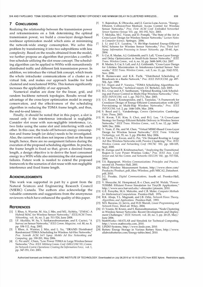
transmission behavior only. As seen in Figs. 5 and 6, using
the proposed cross-layer optimization model, the ratio of
transmission power to (transmitter + receiver) circuit power
consumption determines the transmission behavior. When
the total circuit power consumption is dominant (i.e., the
transmission range is not greater than 4 and 2 hops in Fig. 6
for per-hop distances 5 and 10 meters, respectively), the
nodes send data directly to nodes multihops away (by
increasing the transmission power which is smaller than thetotal circuitpower) with less numberof intermediatenodes to
save energy consumed by transmitter and receiver circuits
(i.e., Figs. 5a and 5b). However, short-distance relay is
preferred if the cost of transmission is significantly higher
than the total energy cost of the transmitter and receiver
circuits. For example, in Fig. 5c, the power for transmission
beyond a distance of two hops away is significantly larger
than the total circuit power; thus, packet relay is done in a
hop-by-hop manner.
6.1.2 Scenario #2: Effect of the Residual Energy and the
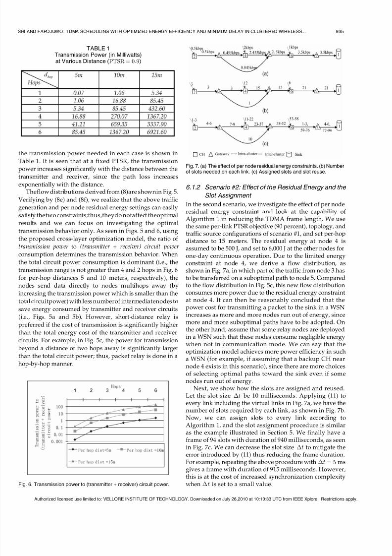
Slot Assignment In the second scenario, we investigate the effect of per noderesidual energy constraint and look at the capability of Algorithm 1 in reducing the TDMA frame length. We usethe same per-link PTSR objective (90 percent), topology, andtraffic source configurations of scenario #1, and set per-hopdistance to 15 meters. The residual energy at node 4 isassumed to be 500 J, and set to 6,000 J at the other nodes forone-day continuous operation. Due to the limited energyconstraint at node 4, we derive a flow distribution, asshown in Fig. 7a, in which part of the traffic from node 3 hasto be transferred on a suboptimal path to node 5. Comparedto the flow distribution in Fig. 5c, this new flow distribution
consumes more power due to the residual energy constraintat node 4. It can then be reasonably concluded that thepower cost for transmitting a packet to the sink in a WSNincreases as more and more nodes run out of energy, sincemore and more suboptimal paths have to be adopted. Onthe other hand, assume that some relay nodes are deployedin a WSN such that these nodes consume negligible energywhen not in communication mode. We can say that theoptimization model achieves more power efficiency in sucha WSN (for example, if assuming that a backup CH nearnode 4 exists in this scenario), since there are more choicesof selecting optimal paths toward the sink even if somenodes run out of energy.
Next, we show how the slots are assigned and reused.Let the slot size Át be 10 milliseconds. Applying (11) toevery link including the virtual links in Fig. 7a, we have thenumber of slots required by each link, as shown in Fig. 7b.Now, we can assign slots to every link according toAlgorithm 1, and the slot assignment procedure is similaras the example illustrated in Section 5. We finally have aframe of 94 slots with duration of 940 milliseconds, as seenin Fig. 7c. We can decrease the slot size Át to mitigate theerror introduced by (11) thus reducing the frame duration.For example, repeating the above procedure with Át ¼ 5 msgives a frame with duration of 915 milliseconds. However,this is at the cost of increased synchronization complexity
when Át is set to a small value.
SHI AND FAPOJUWO: TDMA SCHEDULING WITH OPTIMIZED ENERGY EFFICIENCY AND MINIMUM DELAY IN CLUSTERED WIRELESS... 935
TABLE 1Transmission Power (in Milliwatts)at Various Distance (PTSR ¼ 0:9)
Fig. 6. Transmission power to (transmitter + receiver) circuit power.
Fig. 7. (a) The effect of per node residual energy constraints. (b) Numberof slots needed on each link. (c) Assigned slots and slot reuse.
Authorized licensed use limited to: VELLORE INSTITUTE OF TECHNOLOGY. Downloaded on July 26,2010 at 10:10:33 UTC from IEEE Xplore. Restrictions apply.

5/14/2018 TDMA Scheduling With Optimized Energy Efficiency and Minimum Delay in Clustered W ...
http://slidepdf.com/reader/full/tdma-scheduling-with-optimized-energy-efficiency-and-minimum-delay-
In Fig. 7c, slots 1-3 are reused on link ð6; 7Þ and slots 4-6are reused on link ð7; 1Þ. Of the 94 slots per TDMA frame,six are reused, resulting in a frame length reduction of approximately 7 percent (6=ð94 þ 6Þ) of that without slotreuse. We expect that the benefit of slot reuse will becomesignificant in large-size WSNs. This point is furthersupported by the following scenario #3, where more nodesare used for composing the linear topology.
6.1.3 Scenario #3: Comparison with Non-Cross-Layer
Approach
In the third experiment, we compare the following cross-
layer design (CLD) and non-cross-layer design (NCLD)
approaches:
1. CLD optimal: First, calculate per-link optimal trans-mission power using (7), and then, input the resultsto (6). Also, use Algorithm 1 to derive the TDMAschedules.
2. CLDwithprefixedPTSR objective:First, calculate per-link transmission power using a prefixed PTSRobjective,andthen,inputtheresultsto(6).Algorithm1is used for TDMA schedules.
3. NCLD, shortest path, without slot reuse: In this
NCLD approach, shortest path (in number of hops)is used as a network layer routing scheme for atraffic source (or CH) to send data hop by hop to thesink. TDMA without slot reuse serves as the MAClayer protocol. The distance of one hop for shortestpath routing is determined by the maximumtransmission power configuration.
We investigate the performance of the above three
approaches by first using a linear backbone network
topology consisting of 19 nodes (including the sink). The
distance between two neighboring nodes is 10 meters. As
shown in Fig. 8, CHs 2 and 4 are configured as data sources,
each with a data generation rate of 0.5 kbps. The residual
energy at each node is 6,000 J, which is enough for one day’soperation under the given traffic configuration.
Let the slot size Át be 10 milliseconds. Table 2 gives the backbone network power consumption and TDMA framelength for the approaches of CLD optimal, CLD withprefixed PTSR of 90, 80, and 70 percent, and NCLD withmaximum per-hop distance of 10, 20, and 40 meters andunlimited (unlimited per-hop distance implies that each CHsends data via one hop, directly to the sink). It is observedthat for the NCLD scheme, the TDMA frame lengthdecreases as the maximum per-hop distance increases,since fewer hops are used for relaying the data. The shortestframe length is achieved when there is direct communica-tion (i.e., unlimited per-hop distance) from the data sourcesto the sink. Even though the NCLD (unlimited) approachachieves the smallest frame length, its high power cost issignificantly unacceptable. On the other hand, the NCLDapproach with specified per-hop distance reduces powerconsumption, but at the expense of increased frame length.Clearly, the CLD approach strikes a better balance in thetrade-off between power consumption and frame length,compared to the NCLD approach. It is also seen fromTable 2 that the CLD optimal approach exhibits a betterperformance in terms of energy consumption than the CLDwith prefixed PTSR approach because the former adoptsoptimal energy consumption on a per-link basis. Fig. 9depicts the per bit relay energy consumption (i.e., (7)),
plotted against the hop distance. Compared to the CLDwith prefixed PTSR approach, the CLD optimal approachconsumes the least per bit relay energy. However, it isinteresting to find that similar energy is consumed by theapproaches: CLD optimal and CLD (PTSR ¼ 90 percent)(i.e., CLD with PTSR prefixed at 90 percent) at hop distanceof 40 and 50 meters. The explanation is obtained fromTable 3, which shows the values of PTSR obtained for theCLD optimal approach, as the hop distance is varied.Unlike CLD (PTSR ¼ 90 percent) where the PTSR is fixed at90 percent for all the values of hop distance considered, inthe case of CLD optimal, the PTSR is adaptive to hopdistance. At a hop distance of 40 and 50 m, the PTSR for the
CLD optimal approach is approximately equal to 90 percent,
936 IEEE TRANSACTIONS ON MOBILE COMPUTING, VOL. 9, NO. 7, JULY 2010
Fig. 8. Linear topology used in scenario #3.
Fig. 9. Per bit relay energy consumptions versus hop distance.
TABLE 2Comparison of Different Relay Schemes (Linear Topology)
Authorized licensed use limited to: VELLORE INSTITUTE OF TECHNOLOGY. Downloaded on July 26,2010 at 10:10:33 UTC from IEEE Xplore. Restrictions apply.

5/14/2018 TDMA Scheduling With Optimized Energy Efficiency and Minimum Delay in Clustered W ...
http://slidepdf.com/reader/full/tdma-scheduling-with-optimized-energy-efficiency-and-minimum-delay-
making the per bit relay energy similar to that of CLD
(PTSR ¼ 90 percent).
6.2 Grid Backbone Network
Now, consider a grid backbone network topology with49 backbone nodes, as shown in Fig. 10a. As before, we onlyshow the CHs and gateways in this figure, and the virtuallinks and cluster members are omitted for ease of presentation. As a result of applying the clustering schemeproposed in [17], there are no isolated nodes in the
network. The distance between two successive CHs iseither 20 meters or 28.3 meters, and the diameter of eachcluster is 30 meters. The sink is located at the top left corner, but can be easily extended to the scenario in which the sinkis placed at the center.
We first set the traffic rate at each CH (or thecorresponding virtual link) to 0.2 kbps. The initial residualenergy at each CH or gateway is 6,000 J and the continuousoperation duration is one day. In this experiment, wecompare the performance of the NCLD and CLD ap-proaches. The maximum one hop distance for the NCLDapproach is configured to be either of two values: 10 metersand unlimited. For the CLD with prefixed PTSR approach,the PTSR objective is set to 90 percent.
Fig. 10b gives the flow distribution which is identical(due to the sparseness of the nodes) for the CLDtransmission schemes with or without a prefixed PTSR.Even with the same flow distribution, the CLD optimalscheme (i.e., without a prefixed PTSR), as seen from Table 4,slightly outperforms the one with prefixed PTSR in terms of energy efficiency, same as observed in Section 6.1. FromTable 4 and Fig. 10b, we conclude that the NCLD approach, based on the shortest path routing, which is widely used inthe literature, is less energy efficient than the CLD schemewith or without a prefixed PTSR.
We set the slot size Át to 10 milliseconds. In Table 4, theslots needed for each scheme are presented. Compared tothe NCLD scheme, the advantage of the CLD scheme is itsprovision of the most power-efficient relay scheme (or flowdistribution), based on which a TDMA schedule withminimum frame length (or delay) is derived.
In Fig. 11, we give an example schedule for the CLDschemes (with or without a prefixed PTSR). Since Algo-rithm 1 does not specify the order of the nodes and linksduring scheduling, users can specify the order according tothe application needs. For example, starting slot assignmentat nodes farther away from the sink, or assigning successiveslots to a specific path. In Fig. 11, the scheduling orderis random. After applying Algorithm 1, the frame length is98 slots with duration of 980 milliseconds. Even for this
moderate-size network (with 49 backbone nodes), 14 slots
SHI AND FAPOJUWO: TDMA SCHEDULING WITH OPTIMIZED ENERGY EFFICIENCY AND MINIMUM DELAY IN CLUSTERED WIRELESS... 937
TABLE 3Per-Link PTSR for the CLD Optimal Approach
Fig. 10. (a) Grid backbone network topology. (b) Optimal flow distributionwith or without predetermined PTSR.
TABLE 4Comparison of Different Relay Schemes (Grid Topology)
Authorized licensed use limited to: VELLORE INSTITUTE OF TECHNOLOGY. Downloaded on July 26,2010 at 10:10:33 UTC from IEEE Xplore. Restrictions apply.

5/14/2018 TDMA Scheduling With Optimized Energy Efficiency and Minimum Delay in Clustered W ...
http://slidepdf.com/reader/full/tdma-scheduling-with-optimized-energy-efficiency-and-minimum-delay-
are reused, which means that the average delay is reduced12.5 percent (¼ 14=ð98 þ 14)) compared to using a TDMAframe without slot reuse, given that the same optimal relayscheme is adopted. Undoubtedly, more and more slots can be reused as the network size increases. Thus, compared toother solutions integrating network-wide traffic into onesingle large frame [8], Algorithm 1 effectively reduces theend-to-end latency.
6.3 Random Topology Backbone Network
We further consider a network with random topology. In
Fig. 12, 169 backbone nodes are uniformly distributed in a120 m  120 m. Four nodes are randomly picked up as datasources (which means that traffic is generated in thecorresponding clusters), each with data generation rate of 0.2 kbps.
The optimal relay scheme presented in Fig. 12 isdetermined by the ratio of transmission power to (transmitter+ receiver) circuit power, as concluded in the first scenariousing the linear topology.
Let the slot size Át be 10 milliseconds. RunningAlgorithm 1 gives the TDMA schedule with frame lengthof 32 slots, as shown in Fig. 12. Note that without slot reuseas done in [8], the TDMA frame would be 60 slots using the
same flows in Fig. 12. From (10), the delay is proportional tothe frame length. Thus, we conclude that compared to thescheme in [8] integrating network-wide traffic into onesingle TDMA frame, the average delay is 46.7 percent less inthis scenario using our approach. The percent delayreduction is higher than that obtained for the grid topology, because a larger size network is used. With nodes muchfurther apart, it is natural to expect that more slots can bereused, translating to a higher reduction in the frame lengthfor large-size networks.
For this random topology, we also compare theperformance of the CLD optimal approach to that forNCLD approach as defined in Section 6.1. Table 5 gives the
network-wide (backbone) power consumption and TDMA
frame length (Át ¼ 10 milliseconds) under the CLD optimalapproach and the NCLD approach (with different max-imum hop distance configurations). The NCLD approach isnot available (N/A) when the maximum hop distance is setto 10 meters in this random topology, since some nodesmight not be able to find its next hop within thistransmission range specification. This does not occur inthe grid topology case where the distance between twoneighboring nodes in the same row (or column) is strictly10 meters. When the maximum one hop distance increasesfrom 20 meters to unlimited for the NCLD approach, lessrelay links are involved in forwarding the data to the sinkand the TDMA frame length is reduced. However, due tothe large per-hop transmission distance, the increase of power cost is more significant and dominant compared tothe small gain in frame length reduction.
In Table 5, it is observed that the power consumption of the NCLD approach closest to that of the optimal scheme
takes place when the maximum hop distance is 20 meters, but its frame length is more than double of that obtainedusing the proposed CLD optimal scheme, similar behavior
is observed earlier for the linear backbone topology.Compared to the NCLD approach, the optimal scheme
gives acceptable performance in terms of both energyefficiency and delay.
938 IEEE TRANSACTIONS ON MOBILE COMPUTING, VOL. 9, NO. 7, JULY 2010
Fig. 11. TDMA schedule for a grid backbone network topology.
Fig. 12. TDMA schedule for a random backbone network.
TABLE 5Comparison of Different Relay Schemes (Random Topology)
Authorized licensed use limited to: VELLORE INSTITUTE OF TECHNOLOGY. Downloaded on July 26,2010 at 10:10:33 UTC from IEEE Xplore. Restrictions apply.
5/14/2018 TDMA Scheduling With Optimized Energy Efficiency and Minimum Delay in Clustered W ...
http://slidepdf.com/reader/full/tdma-scheduling-with-optimized-energy-efficiency-and-minimum-delay-
7 CONCLUSIONS
Realizing the relationship between the transmission powerand retransmissions on a link determining the optimaltransmission power, we build a cross-layer design-basednonlinear optimization model which aims at minimizingthe network-wide energy consumption. We solve this
problem by transforming it into two subproblems with lesscomplexity. Based on the results obtained from the model,we further propose an algorithm that provides a conflict-free schedule utilizing the slot reuse concept. The schedul-ing algorithm can be applied to WSNs with nonuniformlydistributed traffic and different link transmission power. Inaddition, we introduce the virtual link concept, which treatsthe whole intracluster communications of a cluster as avirtual link, and makes our approach feasible for bothclustered and nonclustered WSNs. This feature significantlyincreases the applicability of our approach.
Numerical studies are done for the linear, grid, andrandom backbone network topologies. Results reveal the
advantage of the cross-layer optimization model in energyconservation, and the effectiveness of the schedulingalgorithm in reducing the TDMA frame length, and thus,the end-to-end latency.
Finally, it should be noted that in this paper, a slot isreused only if the interference introduced is negligible.Consider slot reuse with non-negligible interference, i.e.,two links using the same slot and interfering with eachother. In this case, the trade-off between energy consump-tion and frame length (or delay) needs to be investigated.Also, the current work does not impose a limit on the framelength; hence, there are no assignment failures during theexecution of the proposed scheduling algorithm. In practice,
the frame length is fixed so that, given a desired framelength, a design objective is to derive the least consumedenergy in a WSN while also minimizing the slot assignmentfailures. Future work is needed to extend the proposedframework to the scenarios of slot reuse with non-negligibleinterference and fixed frame length.
ACKNOWLEDGMENTS
This work was supported in part by a grant from theNatural Sciences and Engineering Research Council(NSERC) Canada. The authors also acknowledge thevaluable comments and suggestions from the anonymousreviewers which have enhanced the quality of this paper.
REFERENCES
[1] I. Rhee, A. Warrier, M. Aia, J. Min, and M.L. Sichitiu, “Z-MAC: AHybrid MAC for Wireless Sensor Networks,” IEEE/ACM Trans.Networking, vol. 16, no. 3, pp. 511-524, June 2008.
[2] I.F. Akyildiz, W. Su, Y. Sankarasubramaniam, and E. Cayirci, “ASurvey on Sensor Networks,” IEEE Comm. Magazine, vol. 40, no. 8,pp. 104-112, Aug. 2002.
[3] I. Rhee, A. Warrier, J. Min, and L. Xu, “DRAND: DistributedRandomized TDMA Scheduling for Wireless Ad-Hoc Networks,”Proc. Seventh ACM Int’l Symp. Mobile Ad Hoc Networking andComputing, pp. 190-201, May 2006.
[4] G. Pei and C. Chien, “Low Power TDMA in Large Wireless SensorNetworks,” Proc. IEEE Military Comm. Conf. (MILCOM ’01), Comm.
for Network-Centric Operations: Creating the Information Force, vol. 1,
pp. 347-351, Oct. 2001.
[5] V. Rajendran, K. Obraczka, and J.J. Garcia-Luna-Aceves, “Energy-Efficient, Collision-Free Medium Access Control for WirelessSensor Networks,” Proc. First ACM Conf. Embedded NetworkedSensor Systems (Sensys ’03), pp. 181-192, Nov. 2003.
[6] T. Melodia, M.C. Vuran, and D. Pompili, “The State of the Art inCross-Layer Design for Wireless Sensor Networks,” Lecture Notesin Computer Science, Springer, 2006.
[7] J. Li and G.Y. Lazarou, “A Bit-Map-Assisted Energy-EfficientMAC Scheme for Wireless Sensor Networks,” Proc. Third Int’l
Symp. Information Processing in Sensor Networks, pp. 55-60, Apr.2004.
[8] S. Cui, R. Madan, A.J. Goldsmith, and S. Lall, “Cross-Layer Energyand Delay Optimization in Small-Scale Sensor Networks,” IEEETrans. Wireless Comm., vol. 6, no. 10, pp. 3688-3699, Oct. 2007.
[9] R. Madan, S. Cui, S. Lall, and A.J. Goldsmith, “Cross-Layer Designfor Lifetime Maximization in Interference-Limited Sensor Net-works,” IEEE Trans. Wireless Comm., vol. 5, no. 11, pp. 3142-3152,Nov. 2006.
[10] R. Ramaswami and K.K. Parhi, “Distributed Scheduling of Broadcasts in a Radio Network,” Proc. IEEE INFOCOM, pp. 497-504, Apr. 1989.
[11] S.C. Ergen and P. Varaiya, “TDMA Scheduling Algorithms forSensor Networks,” technical report, UC Berkeley, July 2005.
[12] R.L. Cruz and A.V. Santhanam, “Optimal Routing, Link Schedul-ing and Power Control in Multi-Hop Wireless Networks,” Proc.IEEE INFOCOM, vol. 1, pp. 702-711, Mar. 2003.
[13] U.C. Kozat, I. Koutsopoulos, and L. Tassiulas, “A Framework forCrosslayer Design of Energy-Efficient Communication with QoSProvisioning in Multi-Hop Wireless Networks,” Proc. IEEEINFOCOM, vol. 2, pp. 1446-1456, Mar. 2004.
[14] S. Boyd and L. Vandenberge, Convex Optimization. CambridgeUniv. Press, 2003.
[15] H. Kwon, T.H. Kim, S. Choi, and B.G. Lee, “A Cross-LayerStrategy for Energy-Efficient Reliable Delivery in Wireless SensorNetworks,” IEEE Trans. Wireless Comm., vol. 5, no. 12, pp. 3689-3699, Dec. 2006.
[16] Y. Yuan, Z. He, and M. Chen, “Virtual MIMO-Based Cross-LayerDesign for Wireless Sensor Networks,” IEEE Trans. VehicularTechnology, vol. 55, no. 3, pp. 856-864, May 2006.
[17] M. Gerla, T.J. Kwon, and G. Pei, “On Demand Routing in LargeAd Hoc Wireless Networks with Passive Clustering,” Proc. IEEEWireless Comm. and Networking Conf. (WCNC ’00), pp. 100-105,Sept. 2000.
[18] M. Zuniga and B. Krishnamachari, “Analyzing the TransitionalRegion in Low Power Wireless Links,” Proc. IEEE Ann. Conf.Sensor and Ad Hoc Comm. and Networks (SECON ’04), pp. 517-526,2004.
[19] T.S. Rappaport, Wireless Communications: Principles and Practice,second ed. Prentice Hall, 2001.
[20] Mica2 Wireless Measurement System, http://www.xbow.com/Products/Product_pdf_files/Wireless_pdf/MICA2_Datasheet.pdf, 2010.
[21] J.G. Proakis, Digital Communications, fourth ed. Prentice-Hall,2001.
[22] V. Shnayder, M. Hempstead, B.-r. Chen, and M. Welsh, “Power-TOSSIM: Efficient Power Simulation for TinyOS Applications,”http://www.eecs.harvard.edu/~shnayder/ptossim, 2010.
[23] G.E. Forsythe, M.A. Malcolm, and C.B. Moler, Computer Methods for Mathematical Computations. Prentice-Hall, 1976.
[24] R.K. Ahuja, T.L. Magnanti, and J.B. Orlin, Network Flows: Theory,
Algorithms, and Applications. Prentice-Hall, 1993.[25] M.S. Bazaraa, J.J. Jarvis, and H.D. Sherali, Linear Programming and
Network Flows, third ed. Wiley, 2004.[26] O. Younis, M. Krunz, and S. Ramasubramanian, “Node Clustering
in Wireless Sensor Networks: Recent Developments and Deploy-ment Challenges,” IEEE Network, vol. 20, no. 3, pp. 20-25, May/
June 2006.[27] MathWorks—MATLAB and Simulink for Technical Computing,
http://www.mathworks.com, 2010.[28] LINDO Systems, http://www.lindo.com, 2010.[29] Battery Energy Storage in Various Battery Sizes, http://www.
allaboutbatteries.com/Energy-tables.html, 2010.
SHI AND FAPOJUWO: TDMA SCHEDULING WITH OPTIMIZED ENERGY EFFICIENCY AND MINIMUM DELAY IN CLUSTERED WIRELESS... 939
Authorized licensed use limited to: VELLORE INSTITUTE OF TECHNOLOGY. Downloaded on July 26,2010 at 10:10:33 UTC from IEEE Xplore. Restrictions apply.

5/14/2018 TDMA Scheduling With Optimized Energy Efficiency and Minimum Delay in Clustered W ...
http://slidepdf.com/reader/full/tdma-scheduling-with-optimized-energy-efficiency-and-minimum-delay-
Liqi Shi received the BEng degree in commu-nication engineering from the National Universityof Defense Technology, China, in 1996, and theMSc degree in electrical and computer engineer-ing in 2007 from the University of Calgary,Canada, where he is currently working towardthe PhD degree in electrical and computerengineering. His previous work experience wasmainly focused on protocol development and
implementation in embedded systems. Cur-rently, his research interests lie in the area of protocol design withQoS support in mobile ad hoc networks and wireless sensor networks.He is a student member of the IEEE.
Abraham O. Fapojuwo received the BEngdegree (with first class honors) from the Uni-versity of Nigeria, Nsukka, Nigeria, in 1980, andthe MSc and PhD degrees in electrical engineer-ing from the University of Calgary, Alberta,Canada, in 1986 and 1989, respectively. From1990 to 1992, he was a research engineer withNovAtel Communications, Ltd., Calgary, wherehe performed numerous exploratory studies on
the architectural definition and performancemodeling of digital cellular systems and personal communicationssystems. From 1992 to 2001, he was with Nortel Networks, where heconducted, led, and directed system-level performance modeling andanalysis of wireless communication networks and systems. In January2002, he joined the Department of Electrical and Computer Engineering,University of Calgary, where he is currently a full professor. He is also anadjunct scientist with TRLabs, Calgary. His current research interestsinclude protocol design and analysis for future-generation wirelesscommunication networks and systems, and best practices in softwarereliability and requirements engineering. He is a registered professionalengineer in the Province of Alberta. He is a senior member of the IEEE.
. For more information on this or any other computing topic,please visit our Digital Library at www.computer.org/publications/dlib.
940 IEEE TRANSACTIONS ON MOBILE COMPUTING, VOL. 9, NO. 7, JULY 2010
Authorized licensed use limited to: VELLORE INSTITUTE OF TECHNOLOGY. Downloaded on July 26,2010 at 10:10:33 UTC from IEEE Xplore. Restrictions apply.