tdc-100 td’s disk controller - broadcaststore.com · the lance design tdc-100 is designed to...
TRANSCRIPT
TDC-100TD’S DISK CONTROLLER
Installation and Operation Manual
Software Version 3.4
September 2007
Lance Design / 27 Fairview Avenue / Ridgefield, Connecticut 06877Tel: 203-894-8206 / Fax: 203-894-8207
www.lancedesign.com

2
CAUTION! HAZARDOUS VOLTAGES ARE EXPOSED WHEN THE TOPCOVER OF THE RACK FRAME IS REMOVED. DO NOT APPLY POWERWITH THE UNIT DISASSEMBLED.
WARRANTY STATEMENT
This equipment is warranted to be free of defects in materials and workmanship fora period of two years from date of delivery. Any necessary repairs resulting fromdefects in materials or in manufacture will be made free of charge provided that theequipment has not been subjected to mechanical or electrical abuse, or modification,as determined by Lance Design, and also that the equipment is returned to LanceDesign with prior authorization.
No liability whatsoever is assumed for consequential damages resulting from the useor failure of this equipment. This warranty is in lieu of all other warranties,expressed or implied, including any implied warranty of fitness for purpose.
COPYRIGHT
All software and hardware designs are copyrighted to Lance Design,1999-2007.

3
Table of Contents
Quick Operation Guide Page 4General Description Page 7Control Panel Description Page 7Menu Items Page 9General Operation Page 14Trigger Function Numbers Page 15Multi-Device Control Rules Page 17Auto-dub From VTR Page 18Multi-Point Loops Page 19TBC Adjustment Control Page 20Installation Page 21GPI Inputs and Outputs Page 22Dipswitch Functions and Connector Pinouts Page 22
4
QUICK OPERATION GUIDE
To enable a device press the corresponding ‘device enable’ button
To enable more than one device, press multiple ‘device enable buttons at thesame time. The first one pressed will be the displayed machine, and will flash
To manually learn the ‘device enable’ data (gang) into the current register, selectthe devices as above, and while still holding the ‘device enable’ buttons down, pressSET on the keypad. The display will say “Now Enabled: XXXX”, indicating theenabled machines for this register.
To select a register, press REG #, then enter three digits on the keypad (000-299).You can also press and hold the REG # key, and use the ‘+’ and ‘-’ keys to scrollthrough the registers. The register number is indicated in the lower right corner ofthe display.
To clear the current register, press and hold the REG # key, and press CLR. Thedisplay will say ‘Register Cleared’. This clears all data from the current register.
To clear ALL registers (or a group of registers), press and hold the REG# button,the MARK IN button, and the MARK OUT button at the same time (3 buttons atonce). The display will say ‘CLR To Clear All!’. If you press the CLR key (whileholding down the above three buttons) the TDC-100 will start clearing registers atthe current register, and ascending until you either press the STOP button, or itreaches the last register (299). This operation is deliberately awkward in order tominimize the chance of doing it accidentally. This function may be inhibited byturning on Dipswitch #1 on the rear of the rack mount frame.
To copy the current register to another, press REG #, then SET. The display willsay “Copy Reg To?”. Enter three digits for the destination register. All register datawill be copied from the current register to the new register.
To mark an in time, press MARK IN. All enabled machines will be marked fromtheir current time code (or timer) values.
To mark an out time, press MARK OUT.
To enter an in or out time from the keypad, key in the time, press SET, and pressMARK IN (for in time) or MARK OUT (for out time). Note: if multiple machines areselected, the time will be entered only on the currently-displayed machine. Theothers will not be affected.
(continued)

5
Quick Operation Guide - continued
To recall an in or out time to the display, press FCN, then MARK IN or MARKOUT. The corresponding time value will be recalled to the display and thescratchpad register, so you can do arithmetic with it if desired (add and subtract). Ifyou ‘double-click’ the REG # button it will recall the in time of the current register (orclip name), for the currently-displayed machine. If there is no value stored in theregister, the display will be all asterisks, indicating no value.
To recall the stored clip name to the display, press FCN, then REG #. If there isa stored clip name for the current device, it will be recalled to the second line of thedisplay, for the purpose of checking it.
To Trim an in time, recall time to display as above (FCN, MARK IN), press ‘+’ or ‘-’,enter the trim value on the keypad, press SET, and press MARK IN to resave it.Outtimes work the same way, with the MARK OUT key. You can set a known clipduration the same way: recall the in time, press ‘+’, enter the desired duration, press‘SET’, press ‘Mark Out’. This takes the in time, adds a duration value to it, andstores it in the out register.
To display the duration of a register (difference between in point and out point),press TM key. If either of the registers is clear, the display will be all asterisks,indicating no value.
To manually learn a speed preset hold down the VAR button and press SET.The display will confirm that the speed has been learned. This speed will be recalledwhen the register is recalled. If you do a learn from the switcher, the current varspeed will be learned into the register.
To Cue Directly to a Keyed-In Time Value enter the time value on the keypad,press ‘SET’, and press ‘CUE’. The device will cue to the entered time. The timevalue will not be stored anywhere. Remember that you must press ‘SET’ beforepressing ‘CUE’. This validates the keypad entry before attempting to send themachine to that position.
To Adjust TBC Levels press ‘FCN’, then ‘MENU’. This will put the controller intothe TBC adjust mode. Use the ‘+’ and ‘-’ keys to select the function, and the knob toadjust. To exit this mode, press ‘FCN’ then ‘MENU’ again. The MENU button willflash when in the TBC adjust mode. If there is no number value displayed after thefunction, then the selected device does not support these commands.
(continued)
6
Quick Operation Guide – continued
To Do a Loop Play define the loop by entering an inpoint and an outpoint. Theminimum duration is 1:15 [one and one-half seconds]. The loop play may beinitiated by either Pbus trigger 5, or by pressing <FCN> the <PLAY> on the frontpanel. You may simulate the Pbus trigger by pressing <FCN>, then <5> on thekeypad. The loop will run until either a STOP, RECUE or RECALL command isreceived. If you turn on LOOP PRESERVE in the menu, only a STOP commandwill halt the loop. You can recall another register without disturbing the loopplayback.
To Do a Multi-point Loop Play set the initial start point in the inpoint of a registernumber between 000 and 099 (first 100 registers). You may also set an outpoint ifdesired, although it isn’t required. The ‘inner loop’ points should be entered in aregister 100 higher. For example, if your ‘outside points’ are in register 25, your‘inside points’ should be in register 125. Minimum duration for the inside loop is oneand one-half seconds. The multi-point loop play may be initiated by Pbus trigger 8,or from the front panel by pressing <FCN>, then <8>. The ddr will start at the initialstart point, then loop between the ‘inner loop’ points. If you send a Pbus trigger 9[<FCN> <9> from the keypad], the controller will stop looping at the first opportunity,and play to the ‘outside’ outpoint [register 25 outpoint in the above example].
To Do an Automatic Transfer (Dub) from a vtr: Set inpoints for both the vtr(playback) and the ddr (record) channels. Press and hold the device button for theddr, then press the vtr’s device button. Both should be lit, with the ddr’s buttonflashing. This is the recorder. Press <FCN>, then <REC>. The vtr will cue back 3seconds from the inpoint and roll. The ddr will go into record at the proper time.
To Add an Offset to All Registers first select the register number where you’d liketo start [usually 000], and select the channels you want to modify [A, B, C, D] bylighting up the device buttons. Press <FCN>, then <TM>. The controller willprompt you to ‘Enter Offset Time’. Enter the time using the keypad. If you want tooffset by a negative number, enter a minus sign first. Press <SET>, then <TM>.The TDC will start modifying both the inpoints and outpoints of all selected channels.You can stop the process by pressing STOP.
To Display Pbus Data for diagnostic purposes, turn on Item 30 in the menu, PBUSDATA DISPLAY. This will cause the ASCII Pbus data to be displayed on line twoof the panel. If the Pbus data is incorrectly formatted (invalid command) a ‘PbusFormat Error’ message will be displayed. Note that this menu item is turned off eachtime the TDC-100 is powered up.
7
GENERAL DESCRIPTION
The Lance Design TDC-100 is designed to provide control of multiple channels ofvideo disk recorder(s) or other devices via P-Bus II interface to Grass Valley Group,Sony, or other production switchers.
This combination allows the user to do the following:
1) Mark playback inpoints when learning an emem effect on the switcher.
2) Recall (cue) the playback device to these cues when effects are recalled.
3) Trigger (roll) the playback device in response to an emem timeline run, loop, orother trigger.
In addition to these functions which are driven from the production switcher, thecontrol panel provides full manual control of the devices, providing normal shuttle,jog, variable play, record, cue, and other commands.
CONTROL PANEL DESCRIPTION
The TDC-100 control panel provides the following controls (left to right on the panel):
Numeric Keypad - for entry of numeric data, register numbers, timecodes, etc.
Plus and Minus Keys - for timecode arithmetic, and for use as up/down keys forscrolling through the menu items.
FCN Key - for selecting alternate functions of some keys. Press and release theFCN key, then press the key whose alternate function you want.
SET Key - operates like an ‘equals’ or ‘enter’ key. To enter a timecode numberfrom the keypad, for example, you would key in the time, press SET, and pressMARK IN. The SET key tells the controller to use the keypad time instead ofmarking from the current disk position
TM Key - used for displaying durations of registers (outpoint minus inpoint). Ifyou have both an inpoint and outpoint set, pressing TM will show you the durationbetween them. This key is also used to enter time values into the timer or timecodegenerator of the controlled device, if this capability is supported.
CLR Key - Clear function. Clears numeric entry and other modes. Functionssomewhat like a ‘cancel’ or ‘escape’ key. Also used to clear registers - see below.
8
REG# - used to select the active register from the 300 available registers. Pressthis key (it lights), and enter a 3-digit register number on the keypad. The activeregister number is displayed in the lower right corner of the display as ‘R 299’, forexample. This key is also used to clear a register (all inpoints and outpoints). Holdthe ‘REG #’ key down and press ‘CLR’. The current register will be cleared.
MARK IN - pressing this key will put the current disk timecode into the INregister, for all enabled devices. Pressing this key after pressing SET will put thekeyed-in timecode value into the IN register (for the displayed device only).Pressing FCN, then MARK IN will recall the current in time to the display. TheMARK IN button will be lighted when ever there is an inpoint stored. If the inpoint iscleared, the button will be dark. If CLIP STORE/RECALL is on in the menu, andthere is a timecode inpoint but no clip name stored in the regitser, the MARK INbutton will flash. This serves as an indicator of the missing clip name.
MARK OUT - same as above for outpoints.
MENU ON - turns on and off the menu mode. Menu items are displayed on thelower line of the display. Use the knob or the +/- keys to scroll through the items.Also selects the TBC Adjust function if pressed after the “FCN” key. In this mode,the menu button light will flash.
MENU SET - used to change the menu items. Pressing this key will toggle themenu choices if there are only two. If there are more than two, it will step throughthem. If you hold this key down, you can use the knob to adjust the menu setting.
CLIP LIST - used to display the clip directory of the disk recorder. If supportedby the disk recorder, the clip names present will be displayed. The numbers on theleft side of the display provide an index, for example 04/12 means this is clip 4 of 12.The names can be scrolled via the +/- keys or the knob.
CUR CLIP - Loads the displayed clip, when “Clip List” above is active.
ENBL PBUS - when this key is lighted, PBUS control from the productionswitcher is enabled. If not lighted, control is inhibited. This button will flash eachtime a valid Pbus command is received. If it’s off, it will flash on. If it’s on, it willflash off.
ENBL LEARN - when this key is lighted, the LEARN function from the productionswitcher is active; that is, when an emem effect is learned on the switcher, the diskinpoints will be marked from the current positions. If you have the disk inpoints set,and don’t want to mark them each time you learn an emem, you can turn thisfunction off (key dark). Recall and Trigger functions are not affected. The ENBLPBUS (above) must be on for this function to operate.
PLAY, RECORD, STOP, CUE, SHTL, JOG, VAR - standard transport controls.When in variable mode, the speed is displayed in the upper right corner of thedisplay. When pressed by itself, the REC button will put the device into EE mode.Pressing REC again, or pressing STOP will cancel EE mode. The REC buttonflashes to indicate that the device is in EE mode.
9
DEVICE ENABLE (A,B,C,D) - four device enable keys corresponding to the fourcontrol ports on the TDC-100. Any lighted key is enabled, and will be sent alltransport commands and PBUS commands. If more than one is enabled, theone that is flashing is the currently-displayed one. The currently-displayeddevice is also tallied by the letter (A,B,C,D) in the upper left corner of the display.
BIG KNOB - used for transport control (jog, shuttle, variable) and for scrollingand setting menu, and for TBC adjustment of devices which support thisfunction.
MENU ITEMS
01 REGISTER LOCK (OFF/ON)Prevents modification to any registers. The intention is to turn the register lock onafter all registers are loaded for a show to prevent inadvertent changes. If you tryto mark, copy, trim, etc. any registers with the lock turned on, you’ll get a ‘RegistersLocked’ error message.
02 PANEL RECALL (ONLY or w/CUEUP)When set to ‘ONLY’, recalling a register from the control panel will only recall theregister information; it won’t cue the disks to those times. When set to ‘w/Cueup’,the controller will recall the register and immediately cue the disks to the registerinpoints. P-bus recalls will always cue the disks, regardless of this menu setting.This would normally be set to ‘Only’ when loading the times into the registers, andperhaps to ‘w/Cueup’ if you’re checking the registers from the panel, or using theTDC-100 to do manual playback.
03 OUTCUE ACTION (NONE, STOP, or RECUE)This item tells the controller what to do when it reaches an outcue. If set to ‘None’ noaction is performed; the machines just keep playing past the outcue. If set to ‘Stop’,the machines will stop when they reach the outcue, and if set to ‘Recue’ they willimmediately recue to the inpoint and stop.
04 CLIP STORE/RECALL (ON/OFF)If this item is turned off, the TDC-100 cues machines based only on timecode (ortimer). The clip name isn’t relevant. If this item is turned on, the name of thecurrent clip is stored when you do a MARK IN, SET IN, or PBUS LEARN, and thisclip will be loaded and cued automatically when the register is recalled or cued.Operation of the store/recall function requires that the controlled devices supportOdetics protocol. The manual clip list/load functions on the control panel operateregardless of this menu setting.

10
05 CLIP LIST MODE (INT / EXT)This item selects the clip list mode that the TDC-100 uses to access the list ofavailable clips on the ddr. The INT mode builds the list within the TDC-100, and willoperate with any ddr which supports Odetics protocol. In this mode the list is limitedto 99 clips. In the EXT mode, the TDC-100 uses special commands added to theOdetics protocol to directly access the clip list in the ddr itself. In this mode there isno limit to the number of clips available. This mode does require that the additionalcommands be supported by the ddr, and so only works properly on certain ddrs(EVS Spotbox).
06 CLIP FILTER (Off, Char = 0-9)The filter only operates in the INT list mode. When this item is off, all available clipnames will be listed, up to the TDC’s limit of 99 clips. When this item is set to a digit(0-9), only clips whose names have a matching first character (0-9) will be listed.
07 RECALL DISPLAYS (NAME / TIME)This item applies only if Item 04 is turned on. If this item is set to NAME, the clipname will be displayed when a register is recalled. If this item is set to TIME, the InTime is displayed when the register is recalled. This menu item only affects thedisplay, all other operation is the same.
08 TIME REFERENCE = (TC/TMR)Selects ‘Tape Timer’ counter or timecode as time reference. May not be supportedby all disk devices. Global command selects mode for all devices. Note: Odeticsmode on the Profile makes the timecode numbers relative to the start of the clip. Ifind this very confusing, and if the clips don’t start at 00:00, you might want to usethe TMR mode to avoid this confusion.
09 TIMER MODE = (12/24)Selects 12 or 24-hour mode for timer.
10 PANEL RECORD LOCK = (ON/OFF)When ON, prevents all devices from being placed into record mode from thecontroller front panel.
11 P-BUS RECORD LOCK = (ON/OFF)When ON, prevents all devices from being placed into record mode via a P-buscommand.
12 RECORD TRIM XX FRAMESUsed to set record timing for automatic dub operation. Typically set to 2 frames
11
13 PANEL BUZZER (OFF/ON/ERR ONLY)Enables or disables the panel buzzer. ‘Off’ is completely off. ‘On’ is on for botherror messages, and register changes like Marks and Learns. ‘Err Only’ is on forerror messages only, off for everything else.
14 PRESERVE LOOP CHA (OFF/ON)When this item is turned on, a loop which is playing on channel A will not bedisturbed by a register recall. The loop will continue to play until it is explicitlystopped. If the item is off, recalling a register will abort the loop, and cue the ddr tothe new time, if the new register has an intime for the looping channel. If no intime,the loop will continue (starting with software version 3.2), even if Preserve Loop isnot turned on.
15 PRESERVE LOOP CH B Same as above for the other channels16 PRESERVE LOOP CH C17 PRESERVE LOOP CH D
18 DEVICE NUM FOR A = (00-23, --)Sets PBUS device number (ID) for the A device. This machine will respond whenthis number matches the device number sent from the switcher. For commandsinvolving multiple machines, if the device number(s) from the switcher match any ofthe enabled machines, the commands will be sent to all enabled machines. Settingthis item to ‘—‘ assigns no device number to channel A, and disables Pbus control ofthis channel (unless ganged).
19 DEVICE NUM FOR B = Same as above for the other channels20 DEVICE NUM FOR C =21 DEVICE NUM FOR D =
22 CH A STATUS (CHECKED / IGNORED)23 CH B STATUS (CHECKED / IGNORED)24 CH C STATUS (CHECKED / IGNORED)25 CH D STATUS (CHECKED / IGNORED)These cause the TDC-100 to either check or ignore the status returned from themachine. If checked, the controller will make sure a machine is present beforetrying to cue it, and will wait until cued before rolling in play (if a cueup command hasbeen issued). If set to IGNORE, the controller will send the commands regardless ofwhat the machine is doing. It may be useful to set one or more of these toIGNORED if a machine is powered down, or disconnected. This would allow you torehearse your effects without modifying the registers. These menu items are set to‘CHECKED’ each time the TDC-100 is powered up, and this is the setting thatshould normally be used.

12
26 GPI INPUTS (DISABLED/ENABLED)Enables the (5) GPI Inputs available on the ‘RS-232/GPI’ connector on the rearpanel of the rack frame. These GPI inputs have the following functions:
GPI 0 - StopGPI 1 - PlayGPI 2 - RecueGPI 3 - Recall Register 000GPI 4 - Recall Register 001
27 GPI OUTPUTS (DISABLED/ENABLED)Enables the (5) GPI Outputs available on the RS-232/GPI connector. The GPIoutputs are triggered when the TDC exits a multi-loop and begins playing the roll-out(or tail) of a multi-loop animation. These GPI outputs have the following functions:
GPI Out 0 - Triggered when Channel A exits a Multi-loopGPI Out 1 - Triggered when Channel B exits a Multi-loopGPI Out 2 - Triggered when Channel C exits a Multi-loopGPI Out 3 - Triggered when Channel D exits a Multi-loopGPI Out 4 - Triggered when any of the four channels exits a Multi-loop
28 GPI OUTPUTS ACTIVE (LOW/HIGH)Selects the polarity of the GPI outputs. If item is set to LOW, the outputs will resthigh, and will be pulled low when triggered. If item is set to HIGH, they will rest lowand will be pulled high when triggered. This item is generally set to LOW.
29 SWITCHER TYPE (GVG / SONY)Selects type of production switcher TDC-100 is used with. Affects the triggerfunction numbers (swaps functions 0 and 1).
30 P-BUS PARITY (NONE/ODD/EVEN)Sets parity mode of P-bus port. Should be set to match production switcher. BaudRate is always 38.4K
31 PBUS DATA DISPLAY (OFF/ON)Turning this item on enables a display of received Pbus commands on the TDC’sdisplay, to assist in troubleshooting Pbus problems. This item is always set to OFFat power up.
13
32 VIDEO FRAME RATE (25/30)Selects the video standard being used, in frames per second. For NTSC, 525/60SDI, and any high-def formats that use 30 frames/sec, or 29.97 frames/sec set thisitem to ‘30’. For PAL, 625/25 SDI or other 25 frame/sec standards, select ‘25’. Thissetting must match the video frame rate being used in the ddrs. The controller willoperate with the wrong standard selected, but all time calculations will be wrong, andconfusing things will happen.
There are two more items which may be selected in the menu. These are not menuitems, but are just information displays (they can’t be set by the users).
DEVICE: Displays the type of controlled device, to the extent that the TDC candetermine it. If a Profile or Fast Forward is in ‘BVW’ mode, this item will identifythem as ‘Sony VTR’. If they are in Non-BVW modes, the TDC will try to report whatprotocol is selected. The frame rate of the controlled device will also be displayed.
TDC FIRMWARE VERSION: Displays the installed firmware in the TDC frame.This manual applies to version 3.4 firmware.
With the exception of the Status Check items which are always turned on at power-up, and the Pbus Data Display, which is always turned off, all menu items areretained in non-volatile memory and will not change when the controller is turned off.
14
GENERAL OPERATION
WHAT IS A REGISTER?
In this controller, a register refers one set of these items:
Device A Inpoint Device A Outpoint Device A Clip Name (if enabled)Device B Inpoint Device B Outpoint Device B Clip Name (if enabled)Device C Inpoint Device C Outpoint Device C Clip Name (if enabled)Device D Inpoint Device D Outpoint Device D Clip Name (if enabled)Device Enable Data (which machines are enabled)Variable-Play Speed Data (Global)
There are 300 registers, stored in non-volatile memory in the controller. They’renumbered 000-299. The register numbers correspond to the switcher’s pbusregister numbers 000-299. When you do learn or recall operations from the switcher(with P-bus enabled), these registers are automatically selected. On most switchersthese correspond directly to the switcher emem numbers. On TDC softwareversions prior to 3.1, the pbus-accessable numbers were restricted to 00-99. Withversion 3.1 all 300 registers are accessible for pbus recalls and learns, if theswitcher supports the larger range.
SWITCHER-INITIATED FUNCTIONS
The production switcher can do the following things:
1) Issue LEARN commands. This happens when you do a emem learn, withlearn/recall enabled in the ‘emem peripheral buss triggers’ menu on the switcher.(‘Enable Pbus and Enable Learn buttons must also be lit on the controller panel).
When you do an emem learn on the switcher, here’s what happens in the controller:
- The controller selects the register whose number matches the emem number- The inpoints of all enabled devices are marked (stored) from current positions- The DEVICE ENABLE status is stored, so that when you recall the register, thesame machines will be selected- The current VAR Speed value is stored in the selected register.
Important note: If you DON’T want these things to happen when you learn anemem, but you want the rest of Pbus control to work, turn off ‘Enable Learn’ on thecontroller. This might be useful when your disk cues are fine, but you just want tomodify an emem effect. Having this button off will prevent remarking the disk cues.
(continued)

15
General Operation - continued
2) Issue RECALL commands. This happens when you recall an emem, again with learn/recall enabled on the switcher, and ‘Enable Pbus’ lit on the controller. Enable Learn does not have to be lit for recall to work.
When you recall an emem on the switcher, here’s what happens in the controller:
- The controller selects the register whose number matches the emem number- The DEVICE ENABLE status is recalled, so the right machines are enabled- Each machine is cued to it’s respective inpoint, awaiting playback.
3) Issue TRIGGER commands. This happens when you have a pbus trigger In an effect timeline, or push the ‘Fire’ button on the switcher menu, or otherwise cause the switcher to send a trigger.
When the switcher sends a TRIGGER, all enabled machines are sent a commandcorresponding to the ‘Function Number’ specified for that trigger in the switchermenu. The function numbers are as follows:
When TDC-100 is in the GVG (Grass Valley) mode:
Function Number Command0 Normal Play1 Recue2 Variable Play (using displayed speed, which
can be learned and recalled)3 Reverse Play at 100%4 Stop5 Loop Play6 Record7 Normal Play8 Multi-Point Loop Start9 Multi-Point Loop Exit10 Select Bank 0 [Registers 000-099]11 Select Bank 1 [Registers 100-199]12 Select Bank 2 [Registers 200-299]
13 and above Normal Play
When TDC-100 is in the Sony mode:
Function Number Command0 Recue1 Normal Play
All others the same as GVG above.

16
The SELECT BANK [0,1,2] triggers are new with version 3.0 software, and allow asingle emem effect to recall up to three different playbacks per channel. If you havean effect in Emem 25 for example, register 025 will be recalled on the TDC whenyou recall that effect. If you send a Trigger 11 from within that effect, register 125will be recalled. If you send a Trigger 12 register 225 will be recalled.
Note that these recalls are just like normal register recalls, in that they affect allchannels. Most triggers affect only machines which have valid device numbers, orare ganged. These do not – they recall the registers regardless of device numbers.Only machines which have valid inpoints and valid device numbers will be cued.
Starting with version 3.2 firmware, all 300 registers are directly accessible from P-bus, if the switcher supports this expanded access. This may make the use ofSELECT BANK triggers unnecessary.
The other new triggers are 8 and 9, which are related to Multi-Point Loops. Pleasesee the detailed operational information section for an explanation of these triggers.

17
MULTI - DEVICE CONTROL RULES
This section describes how the controller handles various combinations of multiplemachines and device enable numbers
The controller front panel controls enabled machines; ones with lighted DeviceEnable buttons. Some front panel functions affect only the Displayed machine -the one whose letter is in the upper left corner of the display. These single-machine functions are Inpoint and Outpoint Setting (not marking), Clip Listingand Loading, and TBC Adjustment.
When the controller receives a P-bus Recall command, it first recalls the gangconfiguration for that register. It then attempts to cue all machines that have avalid device number, whether they are part of the gang or not. In addition, aslong as at least one machine in the gang has a valid device number, allmachines in the gang will be cued. Non-ganged machines can be cued, so longas their device number is enabled on the switcher. The only exceptions to theabove are any channels which are playing loops, and have PRESERVE LOOPturned on in the menu (for that channel). These loops will be left playing duringa register recall.
Generally there is no need to send a ‘recue’ trigger on the first keyframe of youreffect, since just recalling the effect (and thus the TDC register) will cue themachines. If you do put this trigger in your effect you may be causing two‘cueup’ commands to be sent to the DDR at almost the same time, and thismight actually slow the cueing process, or cause other DDR problems.
Trigger functions work the same way as the Recall command. The commandcorresponding to the function number is sent to any device with a valid devicenumber. In addition, the command is sent to all members of the ganged group,so long as one member of the gang has a valid device number.
Note that non-ganged machines may be triggered independently. You cancontrol all 4 ports, even if they’re not part of a gang. You just need to sendappropriate triggers with the right device numbers enabled. Note also that thesetriggers can come at different times. It’s easy, for example, to cue and play akey/fill pair, and while they’re playing, cue and start a loop on another channel,and while that’s all happening, cue and play another clip on the forth channel, allindependently, via the P-bus.
One consideration to be aware of is that if you send multiple triggers at the sametime (on the same keyframe), the TDC100 will stack them, and execute them asit can. This means that you may see some delay in executing multiplecommands that are sent at one time. If you really want accurate control, it’s bestto send no more than one trigger per keyframe.
Outcue Actions are independent, and based on each machine’s individualoutpoints. If you want both a Key and a Fill channel to recue, you must set anoutpoint for each of them. This is a change from earlier versions of software.

18
Detailed Operational Information
Using Auto-Dub Feature to Transfer Material From VTR to Disk
1. Connect the vtr’s remote (9-pin) connector to one of the device control ports onthe TDC-100. (e.g. Device Port D)
2. Connect the DDR that you want to record onto to another port (it’s probablyalready there. For the example, let’s say it’s on port A)
3. Load the tape, and route audio and video from the vtr output to the DDR input.
4. Mark an Inpoint for the VTR. This should be at the start of the material you wantto transfer, of course. Use the MARK IN button, as you normally would, or entera time on the keypad, press SET, then MARK IN.
5. Mark an Inpoint for the DDR in the same way. This will be the point where therecording starts.
6. You can also set an outpoint on the DDR if desired. The recording will stop atthis point. If there is no outpoint, the recording will be open-ended.
7. Enable both machines using the device enable buttons, with the desired recorderbeing the flashing button (current machine). Do this by first pressing down therecorder enable button (A in our example), and while holding it down, press theplayer (vtr) button (D in our example). THIS IS AN IMPORTANT POINT: thecontroller determines which is the player and which is the recorder based onwhich device enable button is flashing. Make sure that the device that you wantto record onto is the flashing one, or you can put the vtr into record! For thisreason, I STRONGLY recommend that you set the record lockout tab on theplayback tape or REC LOCK on the vtr, just in case of finger errors.
8. To start the dub, press FCN, then RECORD (by itself). The controller will cueboth devices (including a 3-second preroll on the vtr), play the vtr, and put theDDR in record at the proper time. The recording will continue until the recorderoutpoint is reached, or until you press the STOP button.
That’s all there is to it. Note that it isn’t possible to record onto two channels(two DDRs) at the same time - you’ll have to do it in two operations.
One other note: there is a menu item called RECORD TRIM. This allowsadjustment of the recorder timing relative to the playback. It is typically set at 2frames, to compensate for various latencies. If your transfers aren’t frame-accurate, you can adjust this value until they are.

19
Using Multipoint Loops
Version 3.0 software has the capability to do multi-point loops, where for exampleyou play a lead-in, loop an internal portion, then (upon receipt of a ‘exit loop’ trigger)play a tail out. Doing this requires four time values.
Start Point --- Loop In --- Loop Out --- End Point
The way the controller accomplishes this is to use a pair of registers. The firstregister must be in the range 000-099. This register contains the Start Point, andthe End Point (the two ‘outside’ times). The second register is in the range 100-199. It contains the Loop In and Loop Out times (the two ‘inside’ times). You selectthe lower register to run the loop. The controller will always look at that number +100 for the two inside times, i.e., if the lower register is 025, the controller will lookat register 125 for the two inside times.
The inside loop must have a minimum duration of 1:15, just like a normal loop, andmust have both an inpoint and an outpoint. The Start Point must be at least as earlyas the Loop In point. There are no requirements placed on the End Point. Thereneed not be a time in that register. If you do want to play a tail out (4-point loop) theEnd Point must be later than the Loop Out.
Once the Start and Loop times are entered, you can start the Multi-point loop (orMLoop, as it’s displayed on the TDC) by sending a Pbus Trigger 8, or by pressing<FCN>, then <8> on the keypad. This will cue the disk to the Start Point, if it isn’tthere already, and begin playing. When the disk gets to the Loop Out point, it willjump back to the Loop In point (the inner loop). It will continue to run this loop untilyou do any one of the following:
Stop the loop with a STOP trigger or button press Recue the loop with a RECUE trigger or button press Recall another register (with PRESERVE LOOP turned off) Send a MULTI-LOOP EXIT Pbus Trigger (trigger 9), or press <FCN>, then <9>.
If you send a MULTI-LOOP EXIT trigger, or press <FCN, then <9>, the disk will exitthe loop at the first opportunity, and play until it reaches the End Point. If there is noEnd Point defined, it will play until stopped. Also, a GPI output will be triggered atthe time that the disk actually exits the loop. This GPI output may be used to triggera switcher effect timed to the tail out portion of the playback, if desired.
Multi-Point Loops do not automatically recue. To play the sequence again, you mustfirst issue a recue command, or recall the register again.
OPERATIONAL TIP: Setting up Multi-point loops requires entering times in tworegisters, 0XX and 1XX. You can easily go between the two by pressing <FCN>,then <+> to go up 100, and <FCN>, then <-> to go down 100. This prevents havingto enter the three-digit register numbers repeatedly.

20
TBC CONTROL WITH THE TDC-100
The TDC-100 can control VTR/Disk TBC or output video processor levels andtiming. This is possible only for vtrs or disk recorders which allow these levels to becontrolled via the standard RS-422 machine control port, via the standard Sonyprotocol.
Machines which allow this include: Panasonic AJ-D350AJ-D351AJ-D360AJ-D580DVC PRO
Sony DVR-10DVR-18DVR-20DVR-28DVW-500IMX VTRsMAV-555
Any Sony VTR equipped withLance Design AIF-422 adapter
Drastic Technologies VVCR Disk
Fast Forward Omega (timing only)
To access this control, just select the device that you want to adjust, and press andrelease the ‘FCN’ button, then press the ‘Menu’ button. Select the parameter thatyou want by using the ‘+’ and ‘-’ keys on the keypad to scroll through the functions.
If there is no number displayed after the parameter label, then the selected devicedoes not support this control protocol.
Levels are adjusted with the jog knob, and may be set to UNITY by pressing the“CLR’ (clear) button on the keypad. This sets only the selected parameter to unity.
This level adjustment data is stored in the device, not in the panel, so that there is noneed to re-set levels if machine assignments are changed.

21
INSTALLATION AND CONNECTIONS
The TDC-100 consists of two pieces: the rack-mounted electronics frame (1RU) andthe control panel. They are interconnected by the supplied 9-conductor cable, whichprovides data communications between the two, and power from the frame to thecontrol panel.
All other connections are made to the electronics frame. The connectors on thisframe are:
DEVICE A - port for disk or vtr A. Standard RS-422 (Sony 9-pin) format DEVICE B DEVICE C DEVICE D - same as above for devices B, C, D. P-BUS IN - P-bus II connection to production switcher - 38.4K Baud P-BUS LOOP - Pin-to-pin looping connection to P-Bus IN connector for
extending P-bus connections to other devices. CONTROL PANEL - Connection to TDC-100 Control Panel (special cable) RS-232 / GPI - RS-232 port for PC upload/download of register data, and
GPI input and output connections. EXT REF IN - Looping BNC connectors for reference (analog) video.
This reference is required for accurate control. POWER - 95-250 volts, 50/60 Hz. Power consumption is <10W
GPI INPUT CONNECTIONS
The GPI inputs can be enabled in the menu, and have the following fixedassignments:
GPI 0 - StopGPI 1 - PlayGPI 2 - RecueGPI 3 - Recall Register 000GPI 4 - Recall Register 001
Electrically, the inputs are a 74HC - series input (will accept ‘TTL’ levels), pulled upto +5 volts with a 4.7K resistor. These should be pulled to ground to activate, witheither an open-collector or TTL output, or a dry relay closure.
DO NOT apply external voltage greater than +5 volts to the GPI inputs, orpermanent damage may result.
TDC-100 FRAME REAR PANEL

22
GPI OUTPUT CONNECTIONS
The GPI Output connections also appear on the 15-pin RS-232/GPI connector.These outputs are 74HC-series outputs. They may be used to drive CMOS or TTL-compatible 5-volt inputs only. They are not suitable for pulling down 24v, drivingrelays (other than low-power 5v relays), or other types of interface.
There are five outputs, with the following assignments:
GPI Out 0 - Triggered when Ch A exits a multi-point loopGPI Out 1 - Triggered when Ch B exits a multi-point loopGPI Out 2 - Triggered when Ch C exits a multi-point loopGPI Out 3 - Triggered when Ch D exits a multi-point loopGPI Out 4 - Triggered when A,B,C or D exits a multi-point loop
DIPSWITCH FUNCTIONS
There is an 8-position DIP Switch on the rear of the rack-mount frame. Theseshould all normally be in the OFF or down position. The functions of these switchesare described below.
Sw 1 - ON inhibits the CLEAR ALL register function from the control panelSw 2 - ON causes menu items to be reset to defaults when all reg are clearedSw 3 - On inhibits the ‘No Ext Reference’ message on the panel displaySw 4 - not usedSw 5 - not usedSw 6 - not usedSw 7 – When SW7 and SW8 are both on, the TDC will do a complete memorySw 8 – clear to all zeros at power-up. This is a factory test feature.
23
CONNECTOR PIN-OUTS; INTERCONNECT INFORMATION
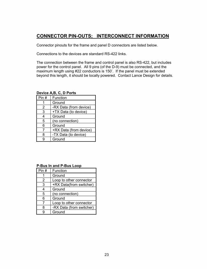
Connector pinouts for the frame and panel D connectors are listed below.
Connections to the devices are standard RS-422 links.
The connection between the frame and control panel is also RS-422, but includespower for the control panel. All 9 pins (of the D-9) must be connected, and themaximum length using #22 conductors is 150’. If the panel must be extendedbeyond this length, it should be locally powered. Contact Lance Design for details.
Device A,B, C, D PortsPin # Function
1 Ground2 -RX Data (from device)3 +TX Data (to device)4 Ground5 (no connection)6 Ground7 +RX Data (from device)8 -TX Data (to device)9 Ground
P-Bus In and P-Bus LoopPin # Function
1 Ground2 Loop to other connector3 +RX Data(from switcher)4 Ground5 (no connection)6 Ground7 Loop to other connector8 -RX Data (from switcher)9 Ground
24
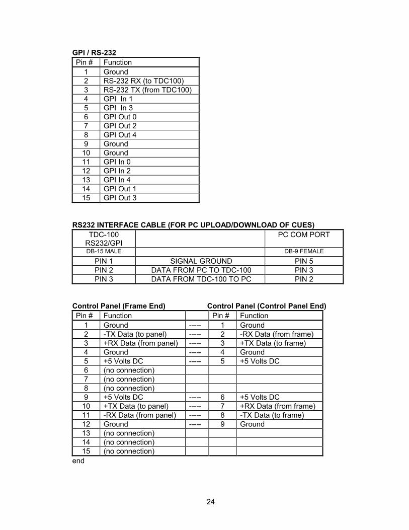
GPI / RS-232Pin # Function
1 Ground2 RS-232 RX (to TDC100)3 RS-232 TX (from TDC100)4 GPI In 15 GPI In 36 GPI Out 07 GPI Out 28 GPI Out 49 Ground
10 Ground11 GPI In 012 GPI In 213 GPI In 414 GPI Out 115 GPI Out 3
RS232 INTERFACE CABLE (FOR PC UPLOAD/DOWNLOAD OF CUES)TDC-100
RS232/GPIPC COM PORT
DB-15 MALE DB-9 FEMALE
PIN 1 SIGNAL GROUND PIN 5PIN 2 DATA FROM PC TO TDC-100 PIN 3PIN 3 DATA FROM TDC-100 TO PC PIN 2
Control Panel (Frame End) Control Panel (Control Panel End)Pin # Function Pin # Function
1 Ground ----- 1 Ground2 -TX Data (to panel) ----- 2 -RX Data (from frame)3 +RX Data (from panel) ----- 3 +TX Data (to frame)4 Ground ----- 4 Ground5 +5 Volts DC ----- 5 +5 Volts DC6 (no connection)7 (no connection)8 (no connection)9 +5 Volts DC ----- 6 +5 Volts DC
10 +TX Data (to panel) ----- 7 +RX Data (from frame)11 -RX Data (from panel) ----- 8 -TX Data (to frame)12 Ground ----- 9 Ground13 (no connection)14 (no connection)15 (no connection)
end