td 200 operator interface - siemens · pdf fileallowing your program to have more control of...
TRANSCRIPT
Preface, Contents
Product Overview and Installation1
Configuring the TD 2002
Operating the TD 2003
Creating Sample Programs4
Appendices
Specifications and ReferenceA
Multiple CPU ConfigurationsB
TroubleshootingC
TD 200 Parameters and Messages
D
Index
10/99Edition 5
TD 200Operator Interface
User Manual
This manual has the order number:6ES7272-0AA00-8BA0
SIMATIC

This manual contains notices which you should observe to ensure your own personal safety, aswell as to protect the product and connected equipment. These notices are highlighted in the manual by a warning triangle and are marked as follows according to the level of danger:
!Danger
indicates that death, severe personal injury or substantial property damage will result if properprecautions are not taken.
!Warning
indicates that death, severe personal injury or substantial property damage can result if properprecautions are not taken.
!Caution
indicates that minor personal injury or property damage can result if proper precautions are nottaken.
Note
draws your attention to particularly important information on the product, handling the product,or to a particular part of the documentation.
Only qualified personnel should be allowed to install and work on this equipment. Qualifiedpersons are defined as persons who are authorized to commission, to ground, and to tag circuits,equipment, and systems in accordance with established safety practices and standards.
Note the following:
!Warning
This device and its components may only be used for the applications described in the catalog orthe technical description, and only in connection with devices or components from other manufacturers which have been approved or recommended by Siemens.
This product can only function correctly and safely if it is transported, stored, set up, and installed correctly, and operated and maintained as recommended.
SIMATIC, SIMATIC NETand SIMATIC HMI are registered trademarks of SIEMENS AG.
Third parties using for their own purposes any other names in this document which refer to trade-marks might infringe upon the rights of the trademark owners.
We have checked the contents of this manual for agreement with thehardware and software described. Since deviations cannot be pre-cluded entirely, we cannot guarantee full agreement. However, thedata in this manual are reviewed regularly and any necessary cor-rections included in subsequent editions. Suggestions for improve-ment are welcomed.
Disclaimer of LiabilityCopyright Siemens AG 1995 All rights reserved
The reproduction, transmission or use of this document or itscontents is not permitted without express written authority.Offenders will be liable for damages. All rights, including rightscreated by patent grant or registration of a utility model or design, arereserved.
Siemens AGBereich Automatisierungs- und AntriebstechnikGeschaeftsgebiet Industrie-AutomatisierungssystemePostfach 4848, D- 90327 Nuernberg
Siemens AG 1995Subject to technical change.
Siemens Aktiengesellschaft 6ES7272-0AA00-8BA0
Notes on Safety
Qualified Personnel
Correct Usage
Trademarks

iiiSIMATIC TD 200 Operator InterfaceC79000-G7076-C205-05
Preface
Purpose
The SIMATIC TD 200 Operator Interface User Manual is a combination user andreference manual that describes the operation of the TD 200 Operator InterfaceModule with an S7-200 programmable logic controller.
Audience
This manual is designed for engineers, programmers, and maintenance personnelwho have a general knowledge of programmable logic controllers and operatorinterfaces.
Scope of This Manual
This manual describes the operation of version 1.1 and later of the TD 200. Thisrelease includes new features and other operational enhancements.
Release Notes
Version 1.1 of the TD 200 includes the following new features:
Supports real (floating-point) numbers
Provides password protection for editable variables and for the Menu mode ofoperation
Supports multiple parameter blocks in a single S7-200 CPU (with a setup menufor entering the V memory address)
Supports 19.2 Kbaud communication rate (with a setup menu for changing thebaud rate)
Sets a bit in the parameter block every time an arrow key is pressed, thusallowing your program to have more control of the TD 200
Includes an alternative character set for creating bar charts
Other enhancements (such as using any key-not just the ESC key-to cancel thescrolling of the messages, or using SHIFT-ENTER to set a variable to 0) eitherimprove the performance of the TD 200 or make it easier to use. For example, youcan now use the SHIFT-UP/DOWN arrow keys to perform acharacter-by-character edit of a variable that is embedded in a message.
Version 1.2 of the TD 200 includes the following new features:
Corrects problems with multi-master networks
Makes the editors more consistent
For upgrades to version 1.2 of the TD 200, contact your distributor.

ivSIMATIC TD 200 Operator Interface
C79000-G7076-C205-05
Agency Approvals
The SIMATIC S7-200 series meets the standards and regulations of the followingagencies.
Underwriters Laboratories, Inc.: UL 508 Listed (Industrial Control Equipment)
Canadian Standards Association: CSA C22.2 Number 142 Certified (Process Control Equipment)
European Community EMC Directive 89/336/EEC and Low Voltage Directive 73/23/EEC
How to Use This Manual
If this is your first experience using an operator interface, read the entire manual. Ifyou are an experienced user, refer to the Table of Contents or Index to find specificinformation.
Related Information
Refer to the following documentation for more detailed information about selectedtopics:
SIMATIC S7-200 Programmable Controller System Manual: providesinformation about installing and programming the S7-200 Micro PLCs, includingthe following topics:
– Installing and wiring the S7-200 CPU and expansion I/O modules, andinstalling the STEP 7-Micro/WIN software
– Designing and entering a program
– Understanding features of the CPU, such as data types and addressingmodes, the CPU scan cycle, password-protection, and networkcommunication
This manual also includes descriptions and examples for the programminginstructions, typical execution times for the instructions, and the data sheets forthe S7-200 equipment.
SIMATIC STEP 7-Micro/DOS User Manual: describes how to use theSTEP 7-Micro/DOS programming software package for the SIMATIC S7-200series of programmable logic controllers.
Preface

vSIMATIC TD 200 Operator InterfaceC79000-G7076-C205-05
SIMATIC Customer Support Hotline
Open round the clock, worldwide:
Johnson City
Nuremberg
Singapore
SIMATIC Hotline
Nuremberg
SIMATIC BASIC Hotline
Johnson City
SIMATIC BASIC Hotline
Singapore
SIMATIC BASIC Hotline
Local time: Mo.-Fr. 7:00 to 17:00
Phone: +49 (911) 895-7000
Fax: +49 (911) 895-7002
E-Mail: [email protected]
GMT: +1:00
Local time: Mo.-Fr. 8:00 to 17:00
Phone: +1 423 461-2522
Fax: +1 423 461-2231
E-Mail: [email protected]
GMT: –5:00
Local time: Mo.-Fr. 8:30 to 17:30
Phone: +65 740-7000
Fax: +65 740-7376
E-Mail: [email protected]
GMT: +8:00
Nuremberg
SIMATIC Authorization Hotline
Local time: Mo.-Fr. 7:00 to 17:00
Phone: +49 (911) 895-7200
Fax: +49 (911) 895-7201
E-Mail: authorization@
nbgm.siemens.de
GMT: +1:00
SIMATIC
Premium Hotline
(fee based, only with
SIMATIC Card)
Local time: Mo.-Fr. 0:00 to 24:00
Phone: +49 (911) 895-7777
Fax: +49 (911) 895-7001
GMT: +01:00
The languages of the SIMATIC Hotlines are generally German and English, in addition, French, Italian and Spanish arespoken on the authorization hotline.
Preface

viSIMATIC TD 200 Operator Interface
C79000-G7076-C205-05
SIMATIC Customer Support Online Services
The SIMATIC Customer Support team offers you substantial additional informationabout SIMATIC products via its online services:
General current information can be obtained from:
– the Internet under http://www.ad.siemens.de/simatic
Current product information leaflets and downloads which you may find usefulare available:
– the Internet under unter http://www.ad.siemens.de/simatic-cs
– via the Bulletin Board System (BBS) in Nuremberg (SIMATIC CustomerSupport Mailbox) under the number +49 (911) 895-7100.
To access the mailbox, use a modem with up to V.34 (28.8 Kbps) withparameters set as follows: 8, N, 1, ANSI; or dial in via ISDN (x.75, 64 Kbps).
Preface

viiSIMATIC TD 200 Operator InterfaceC79000-G7076-C205-05
Contents
Preface iii. . . . . . . . . . . . . . . . . . . . . . . . . . . . . . . . . . . . . . . . . . . . . . . . . . . . . . . . . . . . . . . .
1 Product Overview and Installation 1-1. . . . . . . . . . . . . . . . . . . . . . . . . . . . . . . . . . . . . . .
1.1 Hardware Features 1-2. . . . . . . . . . . . . . . . . . . . . . . . . . . . . . . . . . . . . . . . . . . . . . . . . . . . . .
1.2 Installing the TD 200 1-4. . . . . . . . . . . . . . . . . . . . . . . . . . . . . . . . . . . . . . . . . . . . . . . . . . . . .
1.3 Connecting the Communication Cable 1-6. . . . . . . . . . . . . . . . . . . . . . . . . . . . . . . . . . . . .
1.4 Connecting a Power Cable 1-7. . . . . . . . . . . . . . . . . . . . . . . . . . . . . . . . . . . . . . . . . . . . . . .
1.5 Cleaning the Device 1-7. . . . . . . . . . . . . . . . . . . . . . . . . . . . . . . . . . . . . . . . . . . . . . . . . . . . .
2 Configuring the TD 200 2-1. . . . . . . . . . . . . . . . . . . . . . . . . . . . . . . . . . . . . . . . . . . . . . . . .
2.1 Starting the STEP 7-Micro/WIN TD 200 Configuration Wizard 2-2. . . . . . . . . . . . . . . . . .
2.2 Creating a Sample Program 2-20. . . . . . . . . . . . . . . . . . . . . . . . . . . . . . . . . . . . . . . . . . . . . .
3 Operating the TD 200 3-1. . . . . . . . . . . . . . . . . . . . . . . . . . . . . . . . . . . . . . . . . . . . . . . . . . .
3.1 Using the Display Message Mode 3-2. . . . . . . . . . . . . . . . . . . . . . . . . . . . . . . . . . . . . . . . .
3.2 Using the Menu Mode 3-5. . . . . . . . . . . . . . . . . . . . . . . . . . . . . . . . . . . . . . . . . . . . . . . . . . .
3.3 Viewing Messages 3-6. . . . . . . . . . . . . . . . . . . . . . . . . . . . . . . . . . . . . . . . . . . . . . . . . . . . . .
3.4 Viewing CPU Status Menu 3-7. . . . . . . . . . . . . . . . . . . . . . . . . . . . . . . . . . . . . . . . . . . . . . .
3.5 Forcing I/O 3-9. . . . . . . . . . . . . . . . . . . . . . . . . . . . . . . . . . . . . . . . . . . . . . . . . . . . . . . . . . . . .
3.6 Setting Time and Date in the CPU 3-13. . . . . . . . . . . . . . . . . . . . . . . . . . . . . . . . . . . . . . . . .
3.7 Releasing the Password 3-15. . . . . . . . . . . . . . . . . . . . . . . . . . . . . . . . . . . . . . . . . . . . . . . . .
3.8 Using the TD 200 Setup Menu Option 3-16. . . . . . . . . . . . . . . . . . . . . . . . . . . . . . . . . . . . . .
4 Creating Sample Programs 4-1. . . . . . . . . . . . . . . . . . . . . . . . . . . . . . . . . . . . . . . . . . . . . .
4.1 Using a Text Message to Create a Clock for a CPU 214 4-2. . . . . . . . . . . . . . . . . . . . . .
4.2 Using the Bar Graph Character Set 4-5. . . . . . . . . . . . . . . . . . . . . . . . . . . . . . . . . . . . . . . .
A Specifications and Reference A-1. . . . . . . . . . . . . . . . . . . . . . . . . . . . . . . . . . . . . . . . . . . .
A.1 Certificates, Directives and Declarations A-2. . . . . . . . . . . . . . . . . . . . . . . . . . . . . . . . . . . .
A.2 Approvals A-3. . . . . . . . . . . . . . . . . . . . . . . . . . . . . . . . . . . . . . . . . . . . . . . . . . . . . . . . . . . . . .
A.3 Technical Specifications for Model Number 6ES7 272-0AA00-0YA0 A-4. . . . . . . . . . . .
A.4 ASCII Characters A-7. . . . . . . . . . . . . . . . . . . . . . . . . . . . . . . . . . . . . . . . . . . . . . . . . . . . . . .
A.5 ALT Key Combinations for International and Special Characters A-8. . . . . . . . . . . . . . .
viiiSIMATIC TD 200 Operator Interface
C79000-G7076-C205-05
B Multiple CPU Configurations B-1. . . . . . . . . . . . . . . . . . . . . . . . . . . . . . . . . . . . . . . . . . . .
B.1 Configuring for Multiple CPU Communication B-2. . . . . . . . . . . . . . . . . . . . . . . . . . . . . . . .
B.2 Building a TD/CPU Cable B-4. . . . . . . . . . . . . . . . . . . . . . . . . . . . . . . . . . . . . . . . . . . . . . . .
C Troubleshooting C-1. . . . . . . . . . . . . . . . . . . . . . . . . . . . . . . . . . . . . . . . . . . . . . . . . . . . . . . .
D TD 200 Parameters and Messages D-1. . . . . . . . . . . . . . . . . . . . . . . . . . . . . . . . . . . . . . .
D.1 TD 200 Parameter Block D-2. . . . . . . . . . . . . . . . . . . . . . . . . . . . . . . . . . . . . . . . . . . . . . . . .
D.2 Building the Parameter Block D-4. . . . . . . . . . . . . . . . . . . . . . . . . . . . . . . . . . . . . . . . . . . . .
D.3 Formatting Messages D-9. . . . . . . . . . . . . . . . . . . . . . . . . . . . . . . . . . . . . . . . . . . . . . . . . . . .
D.4 Embedding Data Values in a Text Message D-11. . . . . . . . . . . . . . . . . . . . . . . . . . . . . . . . .
D.5 Understanding Message Types D-20. . . . . . . . . . . . . . . . . . . . . . . . . . . . . . . . . . . . . . . . . . .
D.6 Editing Variables with the TD 200 D-22. . . . . . . . . . . . . . . . . . . . . . . . . . . . . . . . . . . . . . . . . .
Index Index-1. . . . . . . . . . . . . . . . . . . . . . . . . . . . . . . . . . . . . . . . . . . . . . . . . . . . . . . . . . . . .
Contents

1-1SIMATIC TD 200 Operator InterfaceC79000-G7076-C205-05
Product Overview and Installation
The Text Display 200 (TD 200) is a text display and operator interface for theS7-200 family of programmable logic controllers. This manual uses the termsprogrammable logic controller and S7-200 CPU (or CPU) interchangeably.
The following is a list of TD 200 features:
Displays messages read from the S7-200 CPU.
Allows adjustment of designated program variables.
Provides ability to force/unforce I/O points.
Provides ability to set the time and date for CPUs that have real-time clocks.
The TD 200 receives its power either from the S7-200 CPU through the TD/CPUcable or from a separate power supply.
The TD 200 functions as a point-to-point interface (PPI) master when it isconnected to one or more S7-200 CPUs. The TD 200 is also designed to operatewith any other PPI master in a network. Multiple TD 200s can be used with one ormore S7-200 CPUs connected to the same network.
This manual provides you with hardware configuration directions and programmingexamples that require additional equipment. The following is a list of additionalequipment that is necessary to set up and use your TD 200:
S7-200 series programmable logic controller
S7-200 programming device
Programming cable appropriate for your programming device
Chapter Overview
Section Description Page
1.1 Hardware Features 1-2
1.2 Installing the TD 200 1-4
1.3 Connecting the Communication Cable 1-6
1.4 Connecting a Power Cable 1-7
1
1-2SIMATIC TD 200 Operator Interface
C79000-G7076-C205-05
1.1 Hardware Features
Components of the TD 200
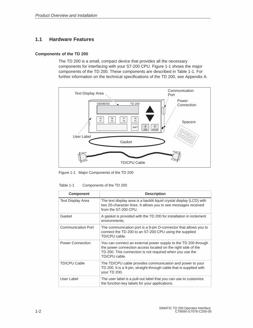
The TD 200 is a small, compact device that provides all the necessarycomponents for interfacing with your S7-200 CPU. Figure 1-1 shows the majorcomponents of the TD 200. These components are described in Table 1-1. Forfurther information on the technical specifications of the TD 200, see Appendix A.
Text Display Area
User Label
SIEMENS TD 200
TD/CPU Cable
PowerConnection
CommunicationPort
Gasket
Spacers
Figure 1-1 Major Components of the TD 200
Table 1-1 Components of the TD 200
Component Description
Text Display Area The text display area is a backlit liquid crystal display (LCD) withtwo 20-character lines. It allows you to see messages receivedfrom the S7-200 CPU.
Gasket A gasket is provided with the TD 200 for installation in inclementenvironments.
Communication Port The communication port is a 9-pin D-connector that allows you toconnect the TD 200 to an S7-200 CPU using the suppliedTD/CPU cable.
Power Connection You can connect an external power supply to the TD 200 throughthe power connection access located on the right side of theTD 200. This connection is not required when you use theTD/CPU cable.
TD/CPU Cable The TD/CPU cable provides communication and power to yourTD 200. It is a 9-pin, straight-through cable that is supplied withyour TD 200.
User Label The user label is a pull-out label that you can use to customizethe function key labels for your applications.
Product Overview and Installation

1-3SIMATIC TD 200 Operator InterfaceC79000-G7076-C205-05
Table 1-1 Components of the TD 200
Component Description
Keys The TD 200 has nine keys. Five of these keys providepredefined, context-sensitive functions, and four keys provideuser-defined functions.
Spacers Self-adhesive spacers are included for mounting the TD 200 to amounting surface. See Figure 1-4.
TD 200 Keyboard Features
The TD 200 keyboard has a total of nine keys. Table 1-2 describes the fivepredefined, context-sensitive command keys.
Table 1-2 Description of Command Keys
CommandKeys
Description
ENTER Use this key to write new data and to acknowledge a message(s).
ESC Use this key to toggle between Display Message mode and Menu modeor to abort an edit.
UP ARROW The UP arrow increments data and scrolls the cursor to the next higherpriority message.
DOWN ARROW The DOWN arrow decrements data and scrolls the cursor to the nextlower priority message.
SHIFT The SHIFT key modulates the value of all of the function keys. SeeTable 1-3 for examples. A flashing “S” is displayed in the lower right ofthe TD 200 display when you press the SHIFT key.
Table 1-3 describes the four user-defined function keys (F1, F2, F3, F4). Youdefine these four function keys in your S7-200 CPU program. Pressing a functionkey sets an M bit. Your program can use this bit to trigger a specific action.
Table 1-3 Description of Function Keys
Function Keys Description
F1 Function key F1 sets the Mx.0 bit.If you press the SHIFT key along with, or prior to, pressing the F1 key,F1 sets the Mx.4 bit.
F2 Function key F2 sets the Mx.1 bit.If you press the SHIFT key along with, or prior to, pressing the F2 key,F2 sets the Mx.5 bit.
F3 Function key F3 sets the Mx.2 bit.If you press the SHIFT key along with, or prior to, pressing the F3 key,F3 sets the Mx.6 bit.
F4 Function key F4 sets the Mx.3 bit.If you press the SHIFT key along with, or prior to, pressing the F4 key,F4 sets the Mx.7 bit.
Product Overview and Installation

1-4SIMATIC TD 200 Operator Interface
C79000-G7076-C205-05
1.2 Installing the TD 200
Preparing the Mounting Surface
Use the template in Figure 1-2 to cut a 138 mm x 68 mm or 5.4 in. x 2.7 in. hole inthe mounting surface (DIN 43700).
138 mm(5.4 in.)
68 mm(2.7 in.)
Figure 1-2 Mounting Surface Hole Dimensions
Preparing the TD 200 for Mounting
Use the following steps to prepare the TD 200 for mounting.
1. Remove the three screws from the rear of the TD 200 using a flat-headscrewdriver. See Figure 1-3.
2. Remove the backplate of the TD 200.
MountingScrews
Figure 1-3 Removing the Three Mounting Screws
Product Overview and Installation
1-5SIMATIC TD 200 Operator InterfaceC79000-G7076-C205-05
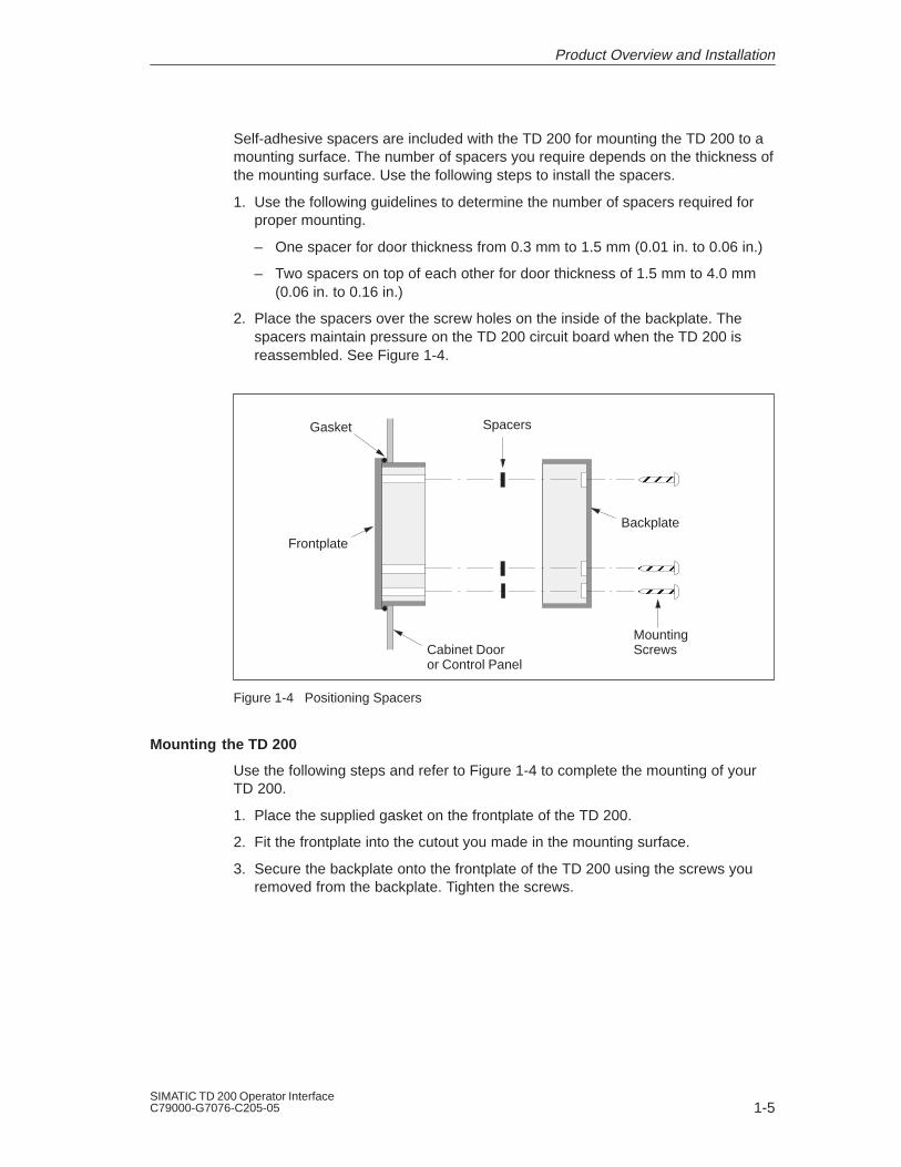
Self-adhesive spacers are included with the TD 200 for mounting the TD 200 to amounting surface. The number of spacers you require depends on the thickness ofthe mounting surface. Use the following steps to install the spacers.
1. Use the following guidelines to determine the number of spacers required forproper mounting.
– One spacer for door thickness from 0.3 mm to 1.5 mm (0.01 in. to 0.06 in.)
– Two spacers on top of each other for door thickness of 1.5 mm to 4.0 mm (0.06 in. to 0.16 in.)
2. Place the spacers over the screw holes on the inside of the backplate. Thespacers maintain pressure on the TD 200 circuit board when the TD 200 isreassembled. See Figure 1-4.
ÉÉÉÉÉÉ
ÉÉÉÉÉÉBackplate
Frontplate
Cabinet Dooror Control Panel
Gasket Spacers
MountingScrews
Figure 1-4 Positioning Spacers
Mounting the TD 200
Use the following steps and refer to Figure 1-4 to complete the mounting of yourTD 200.
1. Place the supplied gasket on the frontplate of the TD 200.
2. Fit the frontplate into the cutout you made in the mounting surface.
3. Secure the backplate onto the frontplate of the TD 200 using the screws youremoved from the backplate. Tighten the screws.
Product Overview and Installation

1-6SIMATIC TD 200 Operator Interface
C79000-G7076-C205-05
1.3 Connecting the Communication Cable
The TD 200 communicates to the S7-200 CPU through the TD/CPU cable. Youcan configure the TD 200 using the TD/CPU cable in the following ways:
One-to-one configuration
Multiple S7-200 CPU configuration
Installing Cable for One-to-One Communication
Use a one-to-one network configuration when you have just one S7-200 CPU toconnect to one TD 200. A one-to-one configuration consists of a TD 200, anS7-200 CPU, and a TD/CPU cable that is supplied with the TD 200.
Figure 1-5 shows you a one-to-one configuration. The TD 200 communicates toand is powered by the S7-200 CPU using the TD/CPU cable.
SIEMENS TD 200
TD 200SIMATICS7-200
S7-200 CPU
TD/CPU Cable
Figure 1-5 One-to-One Configuration
Installing a Multiple CPU Network
Use a multiple CPU network configuration when you have several S7-200 CPUs toconnect to one or more TD 200s. For more information on configuring for multipleCPU communication, refer to Appendix B.
NoteThe TD 200 defaults to address 1 and attempts to communicate to a CPU at address 2.See Section 3.8 to change the network address if other addresses are used.
Product Overview and Installation

1-7SIMATIC TD 200 Operator InterfaceC79000-G7076-C205-05
1.4 Connecting a Power Cable
The TD 200 receives power either from the S7-200 CPU or from an externalplug-in power supply unit.
NoteIf you are using the TD 200 with a network of S7-200 CPUs, special consideration must betaken with the communication and power connections. See Appendix B.
Supplying Power from the S7-200 CPU
Figure 1-6 shows you the TD 200 receiving its power from the CPU through theTD/CPU cable. Use this type of power supply when the distance between theTD 200 and the S7-200 CPU is less than 2.5 m (8.2 ft.).
SIEMENS TD 200
TD 200
SIMATICS7-200
S7-200 CPU
TD/CPU Cable
Figure 1-6 Supplying Power with the TD/CPU Cable
Supplying Power from an External Power Supply
Figure 1-7 shows the TD 200 receiving its power from an external power supply.Use this type of power supply when the distance between the TD 200 and theS7-200 CPU is greater than 2.5 m (8.2 ft.). If you choose to connect the TD 200 tothe CPU with a longer cable (2.5 m/8.2 ft.), use PROFIBUS components (see the SINEC IK10 Catalog). The power supply is available from your Siemensdistributor. See Appendix A for part numbers.
ACSIEMENS TD 200
TD 200 To CPU
Figure 1-7 Supplying Power Using an External Power Supply
1.5 Cleaning the Device
To clean the programming device and display, use only o soft cotton cloth and aneutral cleaning agent.
Product Overview and Installation

1-8SIMATIC TD 200 Operator Interface
C79000-G7076-C205-05
Product Overview and Installation

2-1SIMATIC TD 200 Operator InterfaceC79000-G7076-C205-05
Configuring the TD 200
The TD 200 is a text display device that displays messages enabled by theS7-200 CPU. You do not have to configure or program the TD 200. The onlyoperating parameters stored in the TD 200 are the address of the TD 200, theaddress of the CPU, the baud rate, and the location of the parameter block. Theconfiguration of the TD 200 is stored in a TD 200 parameter block located in thevariable memory (V memory) of the CPU. The operating parameters of theTD 200, such as language, update rate, messages, and message-enabled bits, arestored in the TD 200 parameter block in the CPU.
Upon power-up, the TD 200 reads the parameter block from the CPU. All of theparameters are checked for legal values. If everything is acceptable, the TD 200starts actively polling the message-enabled bits to determine what message todisplay, reads the message from the CPU, and then displays the message.
Chapter Overview
Section Description Page
2.1 Starting the STEP 7-Micro/WIN TD 200 Configuration Wizard 2-2
2.2 Creating a Sample Program 2-20
2

2-2SIMATIC TD 200 Operator Interface
C79000-G7076-C205-05
2.1 Starting the STEP 7-Micro/WIN TD 200 Configuration Wizard
STEP 7-Micro/WIN provides a “wizard” that makes it easy to configure theparameter block and the messages in the data memory area of the S7-200 CPU.The TD 200 Configuration Wizard automatically writes the parameter block andmessage texts to the data block editor after you finish choosing the options andcreating the messages. This data block can then be downloaded to the CPU. Fordetailed information about the TD 200 parameter block and message formats, seeAppendix D.
This chapter contains the procedure for creating a sample TD 200 application. Usethe instructions in this example to create a TD 200 parameter block and threemessages using the TD 200 Configuration Wizard. The first message is text only.The second message contains both text and embedded data. The third message isa text message that requires acknowledgement by the operator.
The example also shows how to use the function keys to enable a message andhow to use the acknowledge- and edit-notification bits within your program.
To open the wizard, select the menu command Tools > T D 200 Wizard... asshown in Figure 2-1.
To navigate through the dialog boxes of the wizard, click on “Next>.” At any timeduring the procedure, click on the “<Prev” button to go back to a previous dialogbox if you need to change or review any of the parameters you have defined. Inthe final dialog box, click on “Finish” to validate and save the parameter block andclose the wizard.
You can view the configured parameter block and messages by opening theSTEP 7-Micro/WIN data block editor.
Configuring the TD 200

2-3SIMATIC TD 200 Operator InterfaceC79000-G7076-C205-05
Project Edit View CPU Debug Tools Setup Window Help
STEP 7-Micro/WIN - c:\microwin\project1.prj
TD 200 Configuration Wizard
CancelNext >
This wizard will help you configure TD 200 messages quickly andeasily. When you are finished, the wizard will generate the supportingdata block code for you.
< Prev
To begin configuring TD 200 messages, click Next.
1, 1
Tools
Instruction Wizard..
TD 200 Wizard...Project Services ...Edit/Add Tools...
Figure 2-1 Accessing the TD 200 Configuration Wizard
Configuring the TD 200
2-4SIMATIC TD 200 Operator Interface
C79000-G7076-C205-05
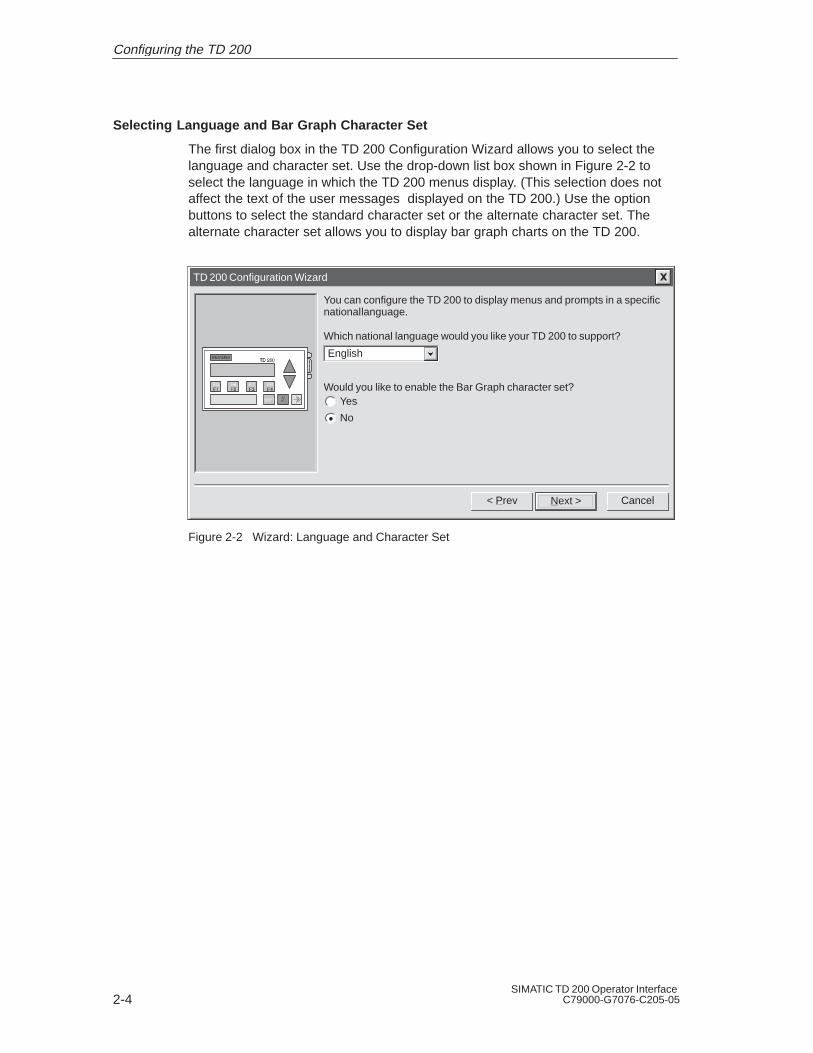
Selecting Language and Bar Graph Character Set
The first dialog box in the TD 200 Configuration Wizard allows you to select thelanguage and character set. Use the drop-down list box shown in Figure 2-2 toselect the language in which the TD 200 menus display. (This selection does notaffect the text of the user messages displayed on the TD 200.) Use the optionbuttons to select the standard character set or the alternate character set. Thealternate character set allows you to display bar graph charts on the TD 200.
TD 200 Configuration Wizard
CancelNext >
You can configure the TD 200 to display menus and prompts in a specificnational language.
< Prev
Would you like to enable the Bar Graph character set?Yes
No
Which national language would you like your TD 200 to support?
English
Figure 2-2 Wizard: Language and Character Set
Configuring the TD 200

2-5SIMATIC TD 200 Operator InterfaceC79000-G7076-C205-05
Enabling Time-of-Day, Force Function, and Password Protection
The dialog box shown in Figure 2-3 allows you to enable Menu mode options andset an edit password.
The Time-of-Day (TOD) and force menu selections allow you to selectively enablethe TOD Clock menu and/or the Force menu. Once a selection is enabled, you areallowed to access that menu in the TD 200. If the menu is not enabled, it does notappear in the TD 200 Menu mode.
The password protection selection allows you to enable a four-digit password (from0000 to 9999). The password controls the ability of the operator to edit variablesembedded in a message and to access the Menu mode. If you enable passwordprotection, a field appears in the dialog box for you to set the password. Thispassword is not the CPU password and it is stored in the TD 200 parameter block.
For this example, use the option buttons to select the modes shown in Figure 2-3.Set 1111 as your password.
TD 200 Configuration Wizard
CancelNext >
!!#! " ! #
!"$
!## $ "
< Prev
Would you like to enable the Time-of-Day (TOD) menu on your TD 200?Yes
No
Would you like to enable the force menu on your TD 200?Yes
No
Would you like to enable password protection?Yes
No 1111Password (0000 - 9999):
Figure 2-3 Wizard: Time-of-Day Clock, Force I/O, and Password Protection
Specifying Function Key Memory Bits and Display Update Rate
The dialog box shown in Figure 2-5 allows you to specify the marker byte(M memory) address for the TD 200 function keys and determine the update rateof the TD 200.
You must reserve eight bits of marker memory (M bits) for the TD 200 to use whena function key is pressed. Your program can inspect these bits and take an actionwhen a key is pressed. One M bit is set by the TD 200 each time thecorresponding function key is pressed. Always reserve an M Area address evenwhen your program does not utilize function keys. Valid address values for specificCPUs are defined in the SIMATIC S7-200 Programmable Controller SystemManual.
Configuring the TD 200

2-6SIMATIC TD 200 Operator Interface
C79000-G7076-C205-05
WarningThe TD 200 sets an M bit each time a function key is pressed. If you do not intend to usefunction keys, and so do not assign an M byte address for function keys, the TD 200defaults to byte M0 for the function keys. If your program uses bits in M0, and a userpresses any function key, the TD 200 sets the corresponding bit in M0, overwriting thevalue assigned to that bit by your program.
Inadvertent changes to M bits could cause your program to behave unexpectedly.Unpredictable controller operation could cause death or serious injury to personnel, and/ordamage to equipment.
Always reserve an M area address, even when your program does not utilize functionkeys.
Figure 2-4 shows a referenced byte (MBn) and shows which bit of the byte is setby each function key.
F4 F3 F2 F1ShiftF4
ShiftF3
ShiftF2
ShiftF1MBn
MSB7 6 5 4 3 2 1
LSB0
Figure 2-4 Bits Set by Each Function Key
The update rate selection determines how often the TD 200 polls the S7-200 CPUfor messages to display. The actual update time may be slower than the time thatyou select because of the size of the message, the processing required, ornetwork traffic.
For this example, select M0 and As fast as possible as shown in Figure 2-5.
TD 200 Configuration Wizard
CancelNext >
&("'#"+&'%#(" '%#(
''%(&'#&'!!#%+'&"'#(!(&'%&%)''&#!!#%+
'&#%''#&'*"("'#"+&$%&&"'&&'+
''!'#%%&$#""("'#"+&$%&&
< Prev
Which byte of M memory would you like to reserve for the TD 200?
($'%''%!"&#*#'"'$# &'#%!&&&'#
&$ + #*#'"*#( +#( ''#$# #%!&&&
0
As fast as possible
Figure 2-5 Wizard: Function Key Memory Bits and Update Rate
Configuring the TD 200
!

2-7SIMATIC TD 200 Operator InterfaceC79000-G7076-C205-05
Selecting Message Size and Number of Messages
The dialog box shown in Figure 2-6 allows you to set the message size andquantity of messages. Select a 20- or 40-character size for your messages. TheTD 200 supports up to 80 messages. Enter a number from 1 to 80 in the text fieldto specify the number of messages you want to create.
For this example, choose three 40-character messages.
TD 200 Configuration Wizard
CancelNext >
The TD 200 allows two message sizes, please select the message sizeyou wish to support.
< Prev
3
20 character message mode - displays two messages at a time
40 character message mode - displays one message at a time
The TD 200 allows you to configure up to 80 messages. How manymessages do you wish to configure?
Figure 2-6 Wizard: Message Size and Number of Messages
Configuring the TD 200

2-8SIMATIC TD 200 Operator Interface
C79000-G7076-C205-05
Specifying Parameter Block Address, Message Enable Address, and Message Location
The dialog box shown in Figure 2-7 allows you to specify starting addresses for theparameter block, the message enable flags, and the messages.
The TD 200 looks for a parameter block in the V memory of the CPU. The defaultlocation for the parameter block is VB0. The default location can be changed. SeeSection 3.8 and Section D.1 for information about placing the parameter block atother locations.
The starting byte for the message enable flags defines the location in V memory atwhich the message enable flags begin. There are eight message enable flagsstored in each byte. Whole bytes must be allocated for message enable flags evenif all the bits are not used. The text in the dialog box shown in Figure 2-7 specifieshow many bytes of V memory are needed for message enable flags based on thenumber of messages you set in the previous (Figure 2-6) dialog box.
The starting byte for message information defines the starting location of the firstmessage in V memory. Messages are placed consecutively in memory. Either 20or 40 bytes are reserved for each message based on your selection in the previousdialog box (Figure 2-6). The text in the dialog box shown in Figure 2-7 specifieshow many bytes are required for messages.
Values for the parameter block, enable flags, and message information startingaddresses are CPU specific. See the SIMATIC S7-200 Programmable ControllerSystem Manual for the valid address ranges for specific CPUs.
For this example, set the parameter block starting byte to 0, the enable flagsaddress to 12, and the message information starting address to 40 as shown inFigure 2-7.
TD 200 Configuration Wizard
CancelNext >
You must now define where you would like the 12 byte parameter definitionto reside in your data block. It is usually located at VB0.
< Prev
0Starting byte for 12 byte parameter block:
12Starting byte for enable flags:
40Starting byte for message information:
You have defined 3 messages requiring 1 consecutive bytes for messageenable flags. You must now define where you would like the enable flags toreside in your data block.
You have defined 3 messages requiring 120 consecutive bytes for themessage information. You must now define where you would like themessage information to reside in your data block.
Figure 2-7 Wizard: Block Address, Enable Flags, and Message Location
Configuring the TD 200
2-9SIMATIC TD 200 Operator InterfaceC79000-G7076-C205-05
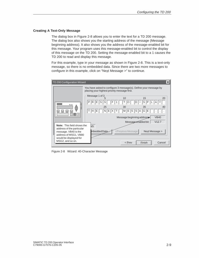
Creating A Text-Only Message
The dialog box in Figure 2-8 allows you to enter the text for a TD 200 message.The dialog box also shows you the starting address of the message (Messagebeginning address). It also shows you the address of the message-enabled bit forthis message. Your program uses this message-enabled bit to control the displayof this message on the TD 200. Setting the message-enabled bit to a 1 causes theTD 200 to read and display this message.
For this example, type in your message as shown in Figure 2-8. This is a text-onlymessage, so there is no embedded data. Since there are two more messages toconfigure in this example, click on “Next Message >” to continue.
TD 200 Configuration Wizard
CancelFinish
You have asked to configure 3 message(s). Define your message byplacing your highest priority message first.
< Prev
Embedded Data...
INS
<Previous Message Next Message >
VB40
V12.7
Message beginning address:
Message enabled bit:
10 15 20
P R E S S F 1 T O D I S P L A Y
Message 1 of 35
30 35 40
T H E N E X T M E S S A G E . . .
25
Note: This field shows theaddress of the particularmessage. VB40 is theaddress of MSG1, VB80would be displayed forMSG2, and so on.
Figure 2-8 Wizard: 40-Character Message
Configuring the TD 200

2-10SIMATIC TD 200 Operator Interface
C79000-G7076-C205-05
Embedding Data Values in a Text Message
You can place a data value within the message that displays on the TD 200. Inorder to display a data value, you must reserve space in the message for the datavalue and for format information. The format information tells the TD 200 how todisplay and edit the data value. The format information requires the space of twocharacters in your message. Word data values require the space of two charactersin addition to the format information (four characters total). Double word or real(floating point) values require the space of four characters in addition to the formatinformation (six characters total).
When you insert a data value into a message, you must be sure there are enoughcharacters to contain the format information and the embedded data value on thecurrent line of the display. For example, if you insert a word value, (two charactersfor the word value and two characters for the format information), you must allowat least four spaces between the starting position of the embedded data value andthe end of the current message line.
The right-most character of an embedded data value serves as the anchor pointfor that value in the TD 200 display. Data values are always right justified to thatanchor point within messages on the TD 200 display. As a data value grows inmagnitude, it utilizes more spaces to the left of the anchor point and can begin touse the spaces occupied by the message text. Be sure to leave sufficient spacebetween the end of your text and the anchor point to allow for the expected rangeof the data value.
The number of display characters used to display a value varies with the size ofthe value. This number of characters required to display a number is not the sameas the number of characters used to store the embedded data value in themessage. The number of display characters required depends on the range ofvalues for that number in a specific application. See Table D-1 for examples of thenumber of display characters required for different display formats.
The TD 200 displays all values as decimal numbers. Positive signed values aredisplayed without a sign. Negative signed values are displayed with a leadingminus sign. Unsigned values are displayed without a sign. A leading zero is usedfor all fractional numbers (for example, 0.5). Real numbers are displayed with thenumber of decimal places you specify. The value is rounded to the specifieddecimal place.
Configuring the TD 200

2-11SIMATIC TD 200 Operator InterfaceC79000-G7076-C205-05
For this example, type in the text shown in Figure 2-9. This example message hastwo embedded data values, one in the top line and one in the second line. Thedata value in the top line is an integer. The data value in the second line is a realnumber.
A word value requires two characters for the value plus two more characters forformat information. Place the cursor at the character position shown in Figure 2-9(four spaces from the right). Click on the “Embedded Data...” button to bring up theEmbedded Data dialog box.
TD 200 Configuration Wizard
CancelFinish
You have asked to configure 3 message(s). Define your message byplacing your highest priority message first.
< Prev
Embedded Data...
INS
<Previous Message Next Message >
VB80
V12.6
Message beginning address:
Message enabled bit:
10 15 20
P R E V . S E T P O I N T :
Message 2 of 35
30 35 40
N E W S E T P O I N T :
25
Place cursor at thecorrect position andclick “EmbeddedData...”
Figure 2-9 Wizard: Embedding Variable Data Value in a Message
Configuring the TD 200

2-12SIMATIC TD 200 Operator Interface
C79000-G7076-C205-05
Formatting the Embedded Data Value
Figure 2-10 shows the Embedded Data dialog box. This dialog box allows you tospecify the data type, format, and display characteristics of an embedded datavalue. You can also select whether or not the message requires acknowledgement,whether the data value can be edited, and whether or not editing requires apassword. Some options depend on the selections you make and do not appearwhen the dialog box opens.
The data format selection defines the size of the data value embedded in themessage:
Select “None” when a message requires acknowledgement but there is noembedded data value to be displayed on the TD 200.
Select “Word“ when the embedded data value is an integer. A word or integervalue requires the space of two characters within your message to hold thedata value.
Select “Double Word” when the embedded data value is a double word or a real(floating point) value. A double word or real value requires the space of fourcharacters within your message to hold the data value.
The display format selection tells the TD 200 whether the data value is signed orunsigned. The TD 200 uses this information when editing the data value. Signedvalues may be either positive or negative numbers. Unsigned values are restrictedto positive numbers.
The selection for digits to the right of the decimal provides scaling for the display ofthe data value. If the data value is an integer, this selection allows you to scale theinteger value for display by specifying the location of the decimal point. Forexample, if the data value is equal to 123 and you select 1 digit to the right of thedecimal, the TD 200 displays 12.3.
The Embedded Data dialog box contains a check box to require acknowledgementof the message. If a message requires acknowledgement, it flashes on the TD 200display until the operator presses ENTER. The dialog box also contains a checkbox for allowing editing of the data value. If this box is selected, the operator canedit the embedded data value. If the box is not checked, the data cannot be edited.
The Embedded Data dialog box also lists the address of the data value within themessage. The user program uses this address to write the data value in themessage.
For this example, make the selections shown in Figure 2-10 and click “OK.”
Configuring the TD 200

2-13SIMATIC TD 200 Operator InterfaceC79000-G7076-C205-05
Embedded Data
CancelOKDelete
None
Word
Double Word
Signed
Unsigned 1
Digits to the right of thedecimal
User must acknowledge message
Is the user allowed to edit this data?
VW98Address of Data Value:
Data Format: Display Format:
Figure 2-10 TD 200 Message: Creating a Word Embedded Data
Configuring the TD 200

2-14SIMATIC TD 200 Operator Interface
C79000-G7076-C205-05
Figure 2-11 shows the message dialog box after you have formatted the firstembedded data value. The grayed fields show the characters used by the formatinformation (always two) and the data value (two for word values).
The second data value in the message is a real number. Real numbers require fourcharacters plus two characters for format information. Move the cursor to position35 and click on “Embedded Data...” to enter the format information for the seconddata value.
TD 200 Configuration Wizard
CancelFinish
You have asked to configure 3 message(s). Define your message byplacing your highest priority message first.
< Prev
Embedded Data...
INS
<Previous Message Next Message >
VB80
V12.6
Message beginning address:
Message enabled bit:
10 15 20
P R E V . S E T P O I N T :
Message 2 of 35
30 35 40
N E W S E T P O I N T :
25
Note: Grayed fieldsare place holders forembedded datavalues.
Figure 2-11 Wizard: Embedded Data Value Place Holder in Message
This variable displays as a real number which requires a double word data format.After you select “Double Word,” the Display Format area allows selection of a real(floating point) number format. For real numbers, the field entitled Digits to the rightof the decimal defines the fixed decimal location of the real number in the TD 200display. The TD 200 rounds a real number to the specified decimal place. Forexample, if the real number value is 123.456 and you select 2 digits to the right ofthe decimal, the TD 200 displays this value as 123.46.
In this example, this variable should be editable by the user. Select the check boxthat allows the user to edit the data. Once the edit-allowed selection has beenmade, two new fields appear in the Embedded Data dialog box.
The Edit Notification Bit field specifies the location of a bit which the TD 200 sets to1 whenever the data value is edited and written to the CPU. The CPU programuses the edit-notification bit to recognize when an editable data value has beenchanged. The program can then read and make use of the edited value. The userprogram is responsible for resetting this bit to 0.
The password-protected check box asks you if you wish to require a password forediting this data value. If checked, the operator must enter a password beforebeing allowed to edit the data value. You selected the password at the beginning ofthe configuration process (see Figure 2-3); it is shown in the Password for Editfield.
Configuring the TD 200

2-15SIMATIC TD 200 Operator InterfaceC79000-G7076-C205-05
After you have made the selections shown in Figure 2-12, click “OK” to continuethe configuration for this example.
Embedded Data
CancelOKDelete
None
Word
Double Word
Signed
Unsigned 1
Digits to the right of thedecimal
User must acknowledge message
Is the user allowed to edit this data?
VD116Address of Data Value:
V114.2Edit Notification Bit:
Should the user edit of data be Password-protected?
Data Format: Display Format:
1111
Password for Edit:
Note: These fieldsappear only whencertain options arechosen.
Real (floating point)
Figure 2-12 Embedded Data: Making the Data Editable and Password Protected.
Figure 2-13 shows the message dialog box after you have completed yourselections for both embedded data values in this message. Click “Next Message>” to continue the example.
TD 200 Configuration Wizard
CancelFinish
You have asked to configure 3 message(s). Define your message byplacing your highest priority message first.
< Prev
Embedded Data...
INS
<Previous Message Next Message >
VB80
V12.6
Message beginning address:
Message enabled bit:
10 15 20
P R E V . S E T P O I N T :
Message 2 of 35
30 35 40
N E W S E T P O I N T :
25
Figure 2-13 Wizard: Completed Second Message
Configuring the TD 200

2-16SIMATIC TD 200 Operator Interface
C79000-G7076-C205-05
Creating a Message That Requires Acknowledgement
To ensure that important messages are displayed and acknowledged by anoperator, you can configure a message to require acknowledgement. Thismessage flashes when displayed on the TD 200. The operator must press theENTER key on the TD 200 to acknowledge the message.
When the message is acknowledged, the following things happen:
The message stops flashing.
The acknowledge-notification bit is set in the CPU.
The message-enabled bit for this message is reset in the CPU.
To force acknowledgement of a message, embed a format word in the message.The format word tells the TD 200 how to display the message. The format worduses two contiguous characters within your message. Since there is no dataassociated with this format word, the format word can be placed anywhere in yourmessage (not just at the end). The format characters appear as blank spaces onthe TD 200 display.
For this example, enter the message text as shown in Figure 2-14. Place thecursor on the 39th digit position and click on “Embedded Data...” button below.
TD 200 Configuration Wizard
CancelFinish
You have asked to configure 3 message(s). Define your message byplacing your highest priority message first.
< Prev
Embedded Data...
INS
<Previous Message Next Message >
VB120
V12.5
Message beginning address:
Message enabled bit:
10 15 20
A C K N O W L E D G E M E S S A G E
Message 3 of 35
30 35 40
B Y P R E S S I N G E N T E R . . .
25
Place cursor on the39th position and click“Embedded Data...”
Figure 2-14 Wizard: Embedding Data to Require Acknowledgement
Configuring the TD 200

2-17SIMATIC TD 200 Operator InterfaceC79000-G7076-C205-05
The Embedded Data dialog box is shown in Figure 2-15. For this message, selecta data format of “None” since there is no data to be displayed. To forceacknowledgement of the message, select the “User must acknowledge message”check box.
NoteIf you have more than one embedded data value in a message, you only need to selectthe acknowledgement check box for the first embedded data value in the message. TheTD 200 ignores the acknowledge bit in all subsequent data values of the message.
For this example, make the selections shown in Figure 2-15 and click on the “OK”button to return to the message configuration dialog box.
Embedded Data
CancelOKDelete
None
Word
Double Word
Signed
Unsigned 0
Digits to the right of thedecimal
User must acknowledge message
Is the user allowed to edit this data?
Data Format: Display Format:
Figure 2-15 Embedded Data: Requiring Acknowledgement of Message
Configuring the TD 200
2-18SIMATIC TD 200 Operator Interface
C79000-G7076-C205-05
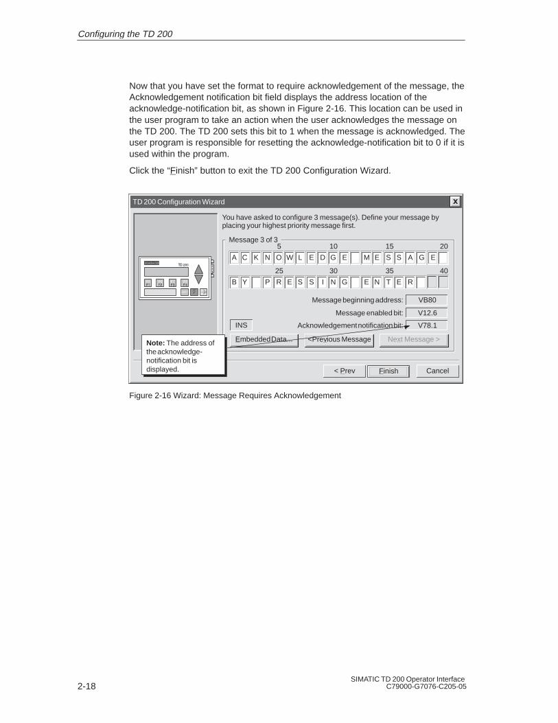
Now that you have set the format to require acknowledgement of the message, theAcknowledgement notification bit field displays the address location of theacknowledge-notification bit, as shown in Figure 2-16. This location can be used inthe user program to take an action when the user acknowledges the message onthe TD 200. The TD 200 sets this bit to 1 when the message is acknowledged. Theuser program is responsible for resetting the acknowledge-notification bit to 0 if it isused within the program.
Click the “Finish” button to exit the TD 200 Configuration Wizard.
TD 200 Configuration Wizard
CancelFinish
You have asked to configure 3 message(s). Define your message byplacing your highest priority message first.
< Prev
Embedded Data...
INS
<Previous Message Next Message >
VB80
V12.6
Message beginning address:
Message enabled bit:
10 15 20
A C K N O W L E D G E M E S S A G E
V78.1Acknowledgement notification bit:
Message 3 of 3
Note: The address ofthe acknowledge-notification bit isdisplayed.
5
30 35 40
B Y P R E S S I N G E N T E R
25
Figure 2-16 Wizard: Message Requires Acknowledgement
Configuring the TD 200

2-19SIMATIC TD 200 Operator InterfaceC79000-G7076-C205-05
Viewing the TD 200 Parameter Block and Messages
The TD 200 Configuration Wizard creates a data block containing the TD 200parameter block and messages. You can open the data block editor to view theTD 200 parameter block and messages that were formatted by the wizard.Figure 2-17 shows the data block for the example in this chapter.
Data Block EditorDB
// BEGIN TD200_BLOCK 0// (Comments within this block should not be edited or removed)VB0 ‘TD’ // TD 200 IdentificationVB2 16#10 // Set Language to English, set Update to As fast as possibleVB3 16#71 // Set the display to 40 character mode; Up key V3.2; Down key V3.3VB4 3 // Set the number of messagesVB5 0 // Set the Function Keys notification bits to M0.0 - M0VW6 40 // Set the starting address for messages to VW40VW8 12 // Set the starting address for message enable bits to VW12VW10 1111 // Global Password// MESSAGE 1// Message Enable Bit V12.7VB40 ‘PRESS F1 TO DISPLAY THE NEXT MESSAGE ...’// MESSAGE 2// Message Enable Bit V12.6VB80 ‘PREV. SETPOINT: ’VB96 16#00 // No Edit; No Acknowledgement; No PasswordVB97 16#11 // Signed Word; 1 Digits to the right of the decimal; VW98 16#00 // Embedded Data Value: Move data for display here. VB100 ‘NEW SETPOINT: ’VB114 16#18 // Edit Notification V114.2; No Acknowledgement; Edit Requires PasswVB115 16#51 // Real Double Word; 1 Digits to the right of the decimal;VD116 16#0000 // Embedded Data Value: Move data for display here.// MESSAGE 3// Message Enable Bit V12.5VB120 ‘ACKNOWLEDGE MESSAGE BY PRESSING ENTER:’VB158 16#01 // No Edit; Acknowledgement Notification V158.1; No PasswordVB159 16#00 // No Data; 0 Digits to the right of the decimal;// END TD200_BLOCK 0
Figure 2-17 Data Block Editor Showing a Sample TD 200 Parameter Block
Configuring the TD 200

2-20SIMATIC TD 200 Operator Interface
C79000-G7076-C205-05
2.2 Creating a Sample Program
Click on the Ladder Editor to create and view your program in Ladder Logic. Clickon the Statement List Editor to create and view your program in Statement Listformat. Figure 2-18 shows a sample program in both the Ladder and StatementList editors. This program uses the TD 200 configuration information from theexample created in this chapter.
Download the program and data block to a CPU. Attach a TD 200 to the CPU tosee the messages created with the wizard. Use the following keys on the TD 200:
Press F1 to go to the setpoint message.
Press ENTER to edit the setpoint. Press ENTER again to go to theacknowledge message.
Press ENTER to acknowledge the third message.
Press F2 to enable all three messages at once.
Press F3 to disable all the messages.
Configuring the TD 200

2-21SIMATIC TD 200 Operator InterfaceC79000-G7076-C205-05
NETWORK 1LD SM0.1 // if this is the first scanMOVB 16#80, VB12 // ...enable the first messageMOVB 0, MB0 // ...clear all function key bits
NETWORK 2LD M0.0 // if F1 has been pressedMOVB 16#40, VB12 // ...enable message 2 for displayR M0.0, 1 // ...reset F1 key M bit
NETWORK 3LD V114.2 // if new setpoint edit bit is setR V114.2, 1 // ...reset edit bitMOVR VD116, AC0 // ...get edited real value*R 10.00000, AC0 // ...times 10 for scalingTRUNC AC0, AC1 // ... convert to an integerMOVW AC1, VW98 // ... update prev. setpoint valueMOVB 16#20, VB12 // ...enable message 3 for display
NETWORK 4LD V158.1 // if message 3 acknowledge bit is setR V158.1, 1 // ...reset message 3 ack bitMOVB 16#80, VB12 // ...enable message 1 for display
NETWORK 5LD M0.1 // if F2 has been pressedMOVB 16#E0, VB12 // ...enable all 3 messages at onceR M0.1, 1 // ...reset F2 key M bit
NETWORK 6LD M0.2 // if F3 has been pressedMOVB 0, VB12 // ...disable all messagesR M0.2, 1 // ...reset F3 key M bit
NETWORK 7MEND
Network 1
Ladder Logic Statement List
SM0.1
ENDNetwork 7
IN1VD116
MUL_REN
IN210.00000 OUT AC0
IN16#80
MOV_BEN
OUT VB12
INAC0
TRUNCEN
OUT AC1
IN0
MOV_BEN
OUT MB0Network 2M0.0
IN16#80
MOV_BEN
OUT VB12
M0.0R1
Network 3V114.2 V114.2
R1
INAC1
MOV_WEN
OUT VW98
IN16#20
MOV_BEN
OUT VB12
Network 4V158.1 V158.1
R1
IN16#80
MOV_BEN
OUT VB12
Network 5M0.1
IN16#E0
MOV_BEN
OUT VB12
M0.1R1
Network 6M0.2
IN0
MOV_BEN
OUT VB12
M0.2R1
Figure 2-18 Sample Program in the Ladder and Statement List Editors
Configuring the TD 200

2-22SIMATIC TD 200 Operator Interface
C79000-G7076-C205-05
Configuring the TD 200

3-1SIMATIC TD 200 Operator InterfaceC79000-G7076-C205-05
Operating the TD 200
This chapter describes the two operating modes of the TD 200:
Display Message mode: This is the default operating mode of the TD 200. Thischapter contains a description of the functions available.
Menu mode: You can access up to six different TD 200 menu options. Thischapter contains a description of each menu and its function, steps to accesseach menu and a description of how you can use it.
Chapter Overview
Section Description Page
3.1 Using the Display Message Mode 3-2
3.2 Using the Menu Mode 3-5
3.3 Viewing Messages 3-6
3.4 Viewing CPU Status Menu 3-7
3.5 Forcing I/O 3-9
3.6 Setting Time and Date in the CPU 3-13
3.7 Releasing the Password 3-15
3.8 Using the TD 200 Setup Menu Option 3-16
3

3-2SIMATIC TD 200 Operator Interface
C79000-G7076-C205-05
3.1 Using the Display Message Mode
The Display Message mode is the default operating mode of the TD 200. Whenyou power up the TD 200, the TD 200 enters the Display Message mode andremains in this mode until you enter the Menu mode. The TD 200 returns to theDisplay Message mode from the Menu mode if you do not press any keys for oneminute.
Figure 3-1 shows you the default message of the Display Message mode.
SIEMENS TD 200
Figure 3-1 Display Message Mode
Functions Available
In the Display Message mode, you can perform the following functions:
Scroll through enabled messages
Edit values
Acknowledge a message
There is no cursor on the display in the Display Message mode. The cursor is onlydisplayed when a key is pressed. To show the cursor, you must press either theUP or the DOWN key.
Scrolling through Messages
If there are more messages enabled than the display can show, the TD 200displays the one or two (based on message size) highest priority messages andplaces a flashing DOWN arrow at the right-most character of the second line. Thisindicates that there are more messages available for display. Use the followingsteps to view additional messages:
1. Press the DOWN arrow. The TD 200 displays the next lower prioritymessage(s).
2. Press the UP arrow. The TD 200 displays the next higher priority message(s).
3. Press any key (except the UP or DOWN arrows). The TD 200 exits the scrollingmode.
Operating the TD 200

3-3SIMATIC TD 200 Operator InterfaceC79000-G7076-C205-05
Editing a Value
You can use the TD 200 to modify variables embedded in the messages. Theoperator uses the arrow keys and the ENTER key to select a message and to editvariables.
Use the following procedure to edit a variable:
1. Select a message by pressing either the UP or the DOWN arrow key to placethe cursor on the first character of the desired message.
2. Press ENTER to move the cursor to the least significant (right-most) characterof the first editable variable in the message.
3. If the variable is password-protected, enter the 4-digit password at the promptand press ENTER.
4. Press either the UP or the DOWN arrow key to increment or decrement thevariable. (Pressing and holding either the UP or the DOWN key accelerates theincrement or decrement operation.)
– To move the cursor to the next digit position, press either the SHIFT UP(left) or the SHIFT DOWN (right) keys.
– To reset the variable to 0, press the SHIFT ENTER keys.
5. Press ENTER to write the updated variable to the CPU.
At the same time the updated value is written to the CPU, the correspondingedit-notification bit is set to 1.
If you do not edit the message variable, or abort the edit by pressing ESC, themessage-enable bit is not cleared by the TD 200. The message-enable bit iscleared by the TD 200 only when you write the last editable variable to the CPU.
The UP and DOWN arrows that indicate higher and lower priority messages, if anyare present, are disabled while an edit is in progress. These functions are restoredwhen the edit is completed or aborted.
If there are more editable variables in the message, the cursor moves to the nextvariable. After all of the variables in the message have been edited, themessage-enable bit for the message is cleared in the CPU. The message is thenremoved from the display on the next update cycle.
NoteDue to restrictions in the format used to store real (floating-point) numbers in both theS7-200 CPU and the TD 200, the accuracy of the number is limited to six significant digits.Editing a real number with more than six digits may not change the value of the variable, ormay cause other digits within the number to change:
Changing the least significant (right-most) digit of a real-number variable withmore than six digits may have no effect. For example: if you try to change the“9” in “1234.56789”, the value of the variable does not change.
Changing the most significant (left-most) digit of a real-number variable withmore than six digits may cause other (less significant) digits in the variable tochange.
Operating the TD 200

3-4SIMATIC TD 200 Operator Interface
C79000-G7076-C205-05
You can abort an edit at any time by pressing ESC. This causes the TD 200 toreread the message from the CPU and to display the variables from the CPU.When the edit session is aborted, any values that have already been sent to theCPU (by pressing the ENTER key after modifying the value) are displayed; anyvalue that was modified but not saved is overwritten by the previous (original)value.
When you abort an edit, the cursor returns to the left-most character of themessage. (The message is not removed from the display until all of the edits arecompleted and written to the CPU.) If the message was configured foracknowledgement, the message starts to flash again, since the edit was notcompleted.
NoteAn edit is automatically aborted if you do not press a key after one minute.
Acknowledging a Message
Some messages require acknowledgement. To acknowledge a message, move thecursor to the first character of the message and press ENTER. Messages requiringacknowledgement are not replaced on the display until you acknowledge themessage.
Messages that do not require acknowledgement or editing are replaced on thedisplay if a higher priority message is enabled by the S7-200 CPU. For moreinformation on acknowledging a message, see Section D.5.
Operating the TD 200

3-5SIMATIC TD 200 Operator InterfaceC79000-G7076-C205-05
3.2 Using the Menu Mode
The Menu mode of the TD 200 allows you to view all messages, display theS7-200 CPU status information, view and set the time and date in CPUs withreal-time clocks, force I/O, release the password, and modify the configuration ofthe TD 200.
The TD 200 enters the Menu mode when you press ESC and the cursor is at theleft-most character of a line. The TD 200 immediately displays the first menu itemas shown in Figure 3-2 (providing that password protection is not enabled). If thepassword protection option is enabled, the TD 200 displays a prompt for enteringthe password (a four-digit integer from 0000 to 9999). Enter the correct passwordto view the first menu item as shown in Figure 3-2.
SIEMENS TD 200
Figure 3-2 Menu Mode
Menus Available
The menu items available in the Menu mode are:
View Messages
View CPU Status
Force I/O (if allowed in parameter block)
Set Time and Date (if allowed in parameter block)
Release Password (if enabled)
TD 200 Setup
Selecting Menu Options
To select a menu item, you scroll through the list of available items by pressing theUP and DOWN arrows. When the desired menu item is displayed, press ENTER.
Exiting Menu Mode
The TD 200 exits the Menu mode when you press ESC during the display of oneof the menu items. Also, the TD 200 exits the Menu mode automatically after oneminute and returns to the Display Message mode if you have not pressed anykeys.
Operating the TD 200

3-6SIMATIC TD 200 Operator Interface
C79000-G7076-C205-05
3.3 Viewing Messages
With the View Messages menu, you can sequentially view all of the messages andprocess values stored in the S7-200 CPU. Press the UP and DOWN arrows todisplay the second (and subsequent) message from the programmable logiccontroller.
NoteYou cannot edit process values while you are in the View Messages menu option.
Accessing the Menu
To access the View Messages menu, perform the following steps.
Key Action Display
1. ESC The TD 200 enters the Menu mode.
VIEW MESSAGES
MENU MODE:
2. ENTER The TD 200 enters the View Messagesmenu.
YOUR MESSAGE
Use the UP and DOWN arrows to scroll through messages stored in the S7-200CPU. You cannot edit values in this mode. You can only edit values in the displaymode.
NotePressing ESC at any time when you are viewing messages aborts the message displayand returns you to the Display Message mode. The TD 200 automatically returns to theDisplay mode after one minute if no keys are pressed.
Operating the TD 200

3-7SIMATIC TD 200 Operator InterfaceC79000-G7076-C205-05
3.4 Viewing CPU Status Menu
With the View CPU Status menu, you can verify the S7-200 CPU RUN/STOPstatus and check the CPU for fatal and non-fatal errors. The TD 200 displays theCPU mode first and then displays the fatal and non-fatal errors sequentially.
The TD 200 displays an error message only if an error exists in the S7-200 CPU.The CPU classifies errors as either fatal errors or non-fatal errors. Refer to theSIMATIC S7-200 Programmable Controller System Manual for more informationabout specific errors.
Accessing the Menu
To access the View CPU Status menu, perform the following steps.
Key Action Display
1. ESC The TD 200 enters the Menu mode.
VIEW MESSAGES
MENU MODE:
2. The TD 200 scrolls down the menuoptions one time.
VIEW STATUS
MENU MODE:
3. ENTER The TD 200 enters the View Statusmenu.
STATUS IS DISPLAYED
NotePressing ESC at any time when you are verifying the S7-200 CPU status returns you tothe Display Message mode. The TD 200 automatically returns to the Display mode afterone minute if no keys are pressed.
Viewing Fatal and Non-fatal Errors
If fatal and/or non-fatal errors are present, use the following process to view thefatal and non-fatal errors.
Key Action Display
The TD 200 scrolls down the list oferrors that are present.
ERRORS PRESENT
Operating the TD 200

3-8SIMATIC TD 200 Operator Interface
C79000-G7076-C205-05
Fatal Error Messages
The following is a list of possible fatal error messages, in order of importance:
FATAL WATCHDOG TIMEOUT
FATAL CHECKSUM ERROR
FATAL EEPROM FAILURE
FATAL MC FAILURE [MC is memory cartridge]
FATAL RUNTIME ADDR ERROR
Non-fatal Error Messages
The following is a list of possible non-fatal error messages, in order of importance:
NON-FATAL DIVIDE BY ZERO
NON-FATAL QUEUE OVERFLOW
NON-FATAL I/O ERROR MOD x [x = module number]
The NON-FATAL I/O ERROR MOD x failure message displays the number ofthe I/O module that has failed. In the case of multiple failures, this message isdisplayed multiple times, one time for each failed module. The modulenumbering is zero to six, corresponding to the CPU specification for expansionmodules. Failures in the I/O of the CPU are displayed as module C.
NON-FATAL RUNTIME PROG ERR
The non-fatal run-time program error includes:
– Indirect addressing
– HSC setup and execution errors
– Attempting to execute an illegal instruction (ENI, DISI, or HDEF) inside aninterrupt routine
– Subroutine nesting errors
– TODW data errors
– Simultaneous XMT and RCV errors
Operating the TD 200

3-9SIMATIC TD 200 Operator InterfaceC79000-G7076-C205-05
3.5 Forcing I/O
The Force I/O menu is only available if the force-menu enable is set in the TD 200configuration that is stored in the CPU. The Force I/O menu allows you to forceinputs, force outputs, or unforce all inputs and outputs.
In the S7-200 CPU, you can establish password protection for the force I/Ofunction. The TD 200 reads the password protection level from the CPU. If theforce function is password protected, the TD 200 asks you to enter the CPUpassword.
NoteThe CPU password restricts editing of the force information in the S7-200 CPU. Thispassword is different from the password protection offered by the TD 200, which restrictsthe editing of variables that are embedded in a message.
Accessing the Menu
To access the Force I/O menu, perform the following steps.
Key Action Display
1. ESC The TD 200 enters the Menu mode.
VIEW MESSAGES
MENU MODE:
2. The TD 200 scrolls down the menuoptions two times.
FORCE I/O
MENU MODE:
3. ENTER The TD 200 enters the Force I/Omenu. If a force function is passwordprotected, the TD 200 displays thefollowing.
PASSWORD ********
PASSWORD REQUIRED
NotePressing ESC at any time while you are forcing I/O returns you to the Display Messagemode. The TD 200 automatically returns to the Display Message mode after one minute ifno keys are pressed.
Operating the TD 200
3-10SIMATIC TD 200 Operator Interface
C79000-G7076-C205-05
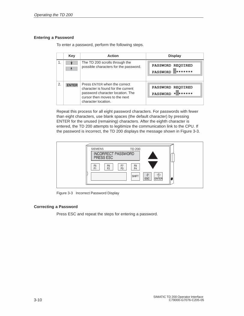
Entering a Password
To enter a password, perform the following steps.
Key Action Display
1. The TD 200 scrolls through thepossible characters for the password.
PASSWORD ********
PASSWORD REQUIRED
2. ENTER Press ENTER when the correctcharacter is found for the currentpassword character location. Thecursor then moves to the nextcharacter location.
PASSWORD ********
PASSWORD REQUIRED
Repeat this process for all eight password characters. For passwords with fewerthan eight characters, use blank spaces (the default character) by pressingENTER for the unused (remaining) characters. After the eighth character isentered, the TD 200 attempts to legitimize the communication link to the CPU. Ifthe password is incorrect, the TD 200 displays the message shown in Figure 3-3.
SIEMENS TD 200
Figure 3-3 Incorrect Password Display
Correcting a Password
Press ESC and repeat the steps for entering a password.
Operating the TD 200

3-11SIMATIC TD 200 Operator InterfaceC79000-G7076-C205-05
Selecting a Force I/O Option
When you enter the correct password, you are allowed into the Force I/O menu.The Force I/O menu allows you to force inputs, force outputs, or unforce all inputsand outputs.
To select a Force I/O option, follow these steps.
1. Scroll through the following options by pressing the UP or DOWN arrow.
FORCE INPUTS?
FORCE OUTPUTS?
UNFORCE ALL I/O?
2. Press ENTER when the desired option is displayed on the second line of thedisplay.
Figure 3-4 shows you one of the Force I/O options that you can select.
SIEMENS TD 200
Figure 3-4 Force I/O Menu Display
NoteUnforcing the I/O points does not place them in the OFF state. Unforcing only removesforce. The points remain in their last state until you manually change them or they arechanged by the program.
CautionA fatal error can occur in the S7-200 CPU if power is removed before the force informationis written to the EEPROM of the CPU.
Such a failure could result in the CPU going into fatal error mode upon next power-up.
To clear the fatal error, rewrite the force information to the CPU or unforce all I/O points,then power cycle the CPU to clear the fatal error.
Operating the TD 200
!

3-12SIMATIC TD 200 Operator Interface
C79000-G7076-C205-05
Forcing and Unforcing an I/O Point
If you select the force outputs option, the display appears as shown in Figure 3-5.The cursor appears on the right-most character of the I/O address.
To change the force status of an I/O point, perform the following steps.
1. Press either the UP or DOWN arrow to change the I/O address to the desiredvalue. The second line of the display shows the force status of the currentaddress.
2. When you reach the desired address, press ENTER to move the cursor to thesecond line.
3. Press either the UP or DOWN arrow to change the force status to one of thefollowing choices:
NOT FORCED
FORCED ON
FORCED OFF
4. When you reach the desired status, press ENTER to write that status to theS7-200 CPU. The cursor moves back to the I/O address.
SIEMENS TD 200
Figure 3-5 Changing the Force Status of an I/O Point
NoteIf you wish to change the force status, press ESC to return the cursor to the I/O address.
With the cursor on the I/O address, press ESC to return to the Force I/O menu.
Operating the TD 200

3-13SIMATIC TD 200 Operator InterfaceC79000-G7076-C205-05
3.6 Setting Time and Date in the CPU
The Set Time and Date option is only available if you set the time-of-day (TOD)menu enable in the TD 200 configuration and if you are using a CPU that supportsthe TOD clock. If the configuration is not set to allow changes to the time, or if yourCPU does not support the TOD clock, you cannot modify the date or time of theCPU.
Figure 3-6 shows you what the TD 200 displays if you try to set the time on anS7-200 CPU that does not contain a clock.
SIEMENS TD 200
Figure 3-6 No Clock in CPU Display
Accessing the Menu
If the TOD menu enable is set and you are using a CPU that supports a TODclock, you can access the Set Time and Date menu by performing the followingsteps.
Key Action Display
1. ESC The TD 200 enters the Menu mode.
VIEW MESSAGES
MENU MODE:
2. The TD 200 scrolls down the menuoptions three times.
SET TIME AND DATE
MENU MODE:
3. ENTER The TD 200 enters the Set Time andDate menu.
28–FEB–95 14:34:12
MONDAY
Operating the TD 200

3-14SIMATIC TD 200 Operator Interface
C79000-G7076-C205-05
The TD 200 reads the current date and time from the CPU and displays it. The firstline of the display contains the date and time. The second line of the displaycontains the day of the week.
NotePressing ESC at any time while you are setting the time and date returns you to theDisplay Message mode. The TD 200 automatically returns to the Display Message modeafter one minute if no keys are pressed.
Editing the Time and Date
After reading the time from the S7-200 CPU, the cursor is placed on theday-of-the-month field.
To change the time and date, perform the following steps.
1. Use the UP and DOWN arrows to increment or decrement the field under thecursor.
2. Press ENTER when the value is correct. The cursor then moves to the nextfield.
NotePressing ENTER when the cursor is on the day-of-the-week field writes the new time anddate to the CPU.
Pressing ESC at any time aborts the edit, rereads the time from the CPU, and returns thecursor to the day field.
Pressing ESC with the cursor on the day field returns you to the Display Message mode.
NoteThe TD 200 does not check for illegal dates. Illegal dates can be written to the CPU.
Operating the TD 200
3-15SIMATIC TD 200 Operator InterfaceC79000-G7076-C205-05
3.7 Releasing the Password
The Release Password option only appears if you have defined a password for theTD 200.
The Release Password option allows the operator to end or pause an editingsession and to return the TD 200 to password protection. The password must thenbe reentered before any editing is allowed.
The TD 200 also has a 2-minute time-out feature which automatically releases thepassword, thereby restoring password protection. If the keypad is inactive (no keysare pressed) for 2 minutes, the TD 200 prompts the operator to enter the passwordagain before editing.
NoteThe Release Password option affects only the password protection offered by the TD 200,which restricts the editing of data values that are embedded in a message. The ReleasePassword option is set in the parameter block for the TD 200. The Release Passwordoption does not affect the CPU password that restricts the editing of a user programrunning on an S7-200 CPU.
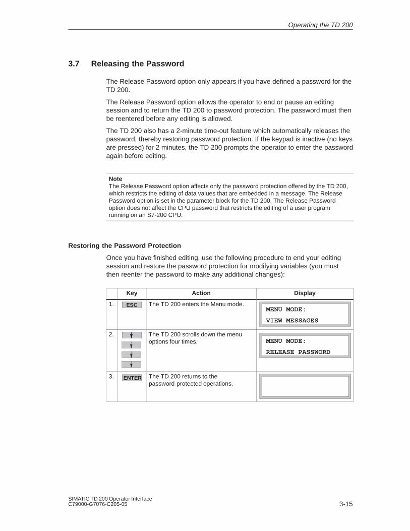
Restoring the Password Protection
Once you have finished editing, use the following procedure to end your editingsession and restore the password protection for modifying variables (you mustthen reenter the password to make any additional changes):
Key Action Display
1. ESC The TD 200 enters the Menu mode.
VIEW MESSAGES
MENU MODE:
2. The TD 200 scrolls down the menuoptions four times.
RELEASE PASSWORD
MENU MODE:
3. ENTER The TD 200 returns to thepassword-protected operations.
Operating the TD 200

3-16SIMATIC TD 200 Operator Interface
C79000-G7076-C205-05
3.8 Using the TD 200 Setup Menu Option
The TD 200 Setup menu allows you to set the network address of the TD 200 andthe S7-200 CPU, the address of the parameter block (stored in V memory of theCPU), and the baud rate for communication. The network addresses allow theTD 200 to be connected to a network with multiple master and slave devices.Entering the address where the TD 200 looks for its parameter block allows you tohave several TD 200 devices connected to a single CPU.
NotePressing ESC with the cursor on the left-most character returns you to the DisplayMessage mode. If you change either of the setup values, the TD 200 reinitializes thecommunications to the CPU.
Setting the Network Address of the TD 200
The Setup Menu allows you to enter the network address for the TD 200. (Thedefault address for the TD 200 is 1.) Use the following procedure to change thenetwork address for the TD 200:
Key Action Display
1. ESC The TD 200 enters the Menu mode.
VIEW MESSAGES
MENU MODE:
2. The TD 200 scrolls down the menuoptions five times.
TD 200 ADDRESS 1
SETUP MENU:
3. ENTER Press ENTER to move the cursor to theaddress field. Use the up or downarrow keys to display the correctaddress.
SETUP MENU:
TD 200 ADDRESS 1
4. ENTER Press ENTER to store the new addressfor the TD 200.
SETUP MENU:
TD 200 ADDRESS 2
NotePressing ESC at any time while setting the network address for the TD 200 aborts the editand returns the cursor to the left-most character of the line.
Operating the TD 200

3-17SIMATIC TD 200 Operator InterfaceC79000-G7076-C205-05
Selecting the CPU Address
The Setup Menu allows you to enter the network address for the CPU. (The defaultaddress for the CPU is 2.) Use the following procedure to change the networkaddress for the CPU:
Key Action Display
1. ESC The TD 200 enters the Menu mode.
VIEW MESSAGES
MENU MODE:
2. The TD 200 scrolls down the menuoptions five times.
TD 200 ADDRESS 1
SETUP MENU:
3. The TD 200 scrolls down the SetupMenu to the CPU address option.
CPU ADDRESS 2
SETUP MENU:
4. ENTER Press ENTER to move the cursor to theaddress field. Use the up or downarrow keys to display the correctaddress.
SETUP MENU:
CPU ADDRESS 2
5. ENTER Press ENTER to store the new addressfor the CPU.
SETUP MENU:
CPU ADDRESS 3
NotePressing ESC at any time while setting the network address for the CPU aborts the editand returns the cursor to the left-most character of the line.
Operating the TD 200

3-18SIMATIC TD 200 Operator Interface
C79000-G7076-C205-05
Entering the Parameter Block Address
The Setup Menu allows you to designate a V memory location where theparameter block (or an offset to the location of the parameter block) is stored in theCPU. The default parameter block address is V0. You can enter any V memoryaddress up to V999.
Use the following procedure to enter the V memory address of the parameter block(or the location of the offset to the parameter block):
Key Action Display
1. ESC The TD 200 enters the Menu mode.
VIEW MESSAGES
MENU MODE:
2. The TD 200 scrolls down the menuoptions five times.
TD 200 ADDRESS 1
SETUP MENU:
3. The TD 200 scrolls down the SetupMenu to the parameter block addressoption.
PARM ADDRESS 0
SETUP MENU:
4. ENTER Press ENTER to move the cursor to theaddress field. Use the up or downarrow keys to display the correctaddress.
SETUP MENU:
PARM ADDRESS 0
5. ENTER Press ENTER to store the V memoryaddress of the parameter block.
SETUP MENU:
PARM ADDRESS 30
NotePressing ESC at any time while entering the address of the parameter block aborts the editand returns the cursor to the left-most character of the line.
Operating the TD 200
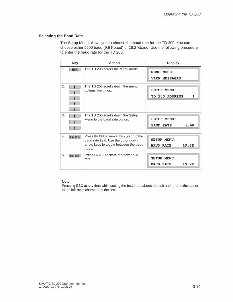
3-19SIMATIC TD 200 Operator InterfaceC79000-G7076-C205-05
Selecting the Baud Rate
The Setup Menu allows you to choose the baud rate for the TD 200. You canchoose either 9600 baud (9.6 Kbaud) or 19.2 Kbaud. Use the following procedureto enter the baud rate for the TD 200:
Key Action Display
1. ESC The TD 200 enters the Menu mode.
VIEW MESSAGES
MENU MODE:
2. The TD 200 scrolls down the menuoptions five times.
TD 200 ADDRESS 1
SETUP MENU:
3. The TD 200 scrolls down the SetupMenu to the baud rate option.
BAUD RATE 9.6K
SETUP MENU:
4. ENTER Press ENTER to move the cursor to thebaud rate field. Use the up or downarrow keys to toggle between the baudrates.
SETUP MENU:
BAUD RATE 19.2K
5. ENTER Press ENTER to store the new baudrate.
SETUP MENU:
BAUD RATE 19.2K
NotePressing ESC at any time while setting the baud rate aborts the edit and returns the cursorto the left-most character of the line.
Operating the TD 200

3-20SIMATIC TD 200 Operator Interface
C79000-G7076-C205-05
Operating the TD 200

4-1SIMATIC TD 200 Operator InterfaceC79000-G7076-C205-05
Creating Sample Programs
This chapter provides sample programs that can be used for understanding howthe TD 200 performs various tasks.
The first program demonstrates how several variables can be placed on oneTD 200 display using ASCII text. A TD 200 and a CPU 214 are used to create aclock. The second program illustrates the bar graph character set.
Chapter Overview
Section Description Page
4.1 Using a Text Message to Create a Clock for a CPU 214 4-2
4.2 Using the Bar Graph Character Set 4-5
4
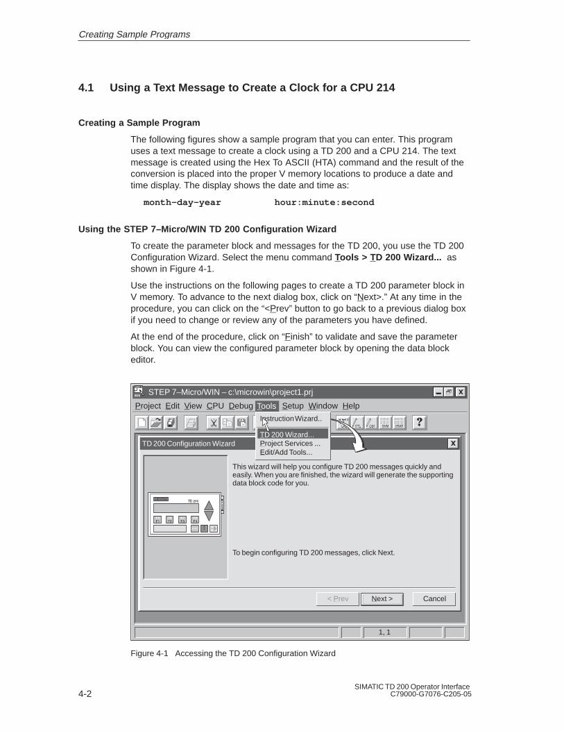
4-2SIMATIC TD 200 Operator Interface
C79000-G7076-C205-05
4.1 Using a Text Message to Create a Clock for a CPU 214
Creating a Sample Program
The following figures show a sample program that you can enter. This programuses a text message to create a clock using a TD 200 and a CPU 214. The textmessage is created using the Hex To ASCII (HTA) command and the result of theconversion is placed into the proper V memory locations to produce a date andtime display. The display shows the date and time as:
month–day-year hour:minute:second
Using the STEP 7–Micro/WIN TD 200 Configuration Wizard
To create the parameter block and messages for the TD 200, you use the TD 200Configuration Wizard. Select the menu command Tools > T D 200 Wizard... asshown in Figure 4-1.
Use the instructions on the following pages to create a TD 200 parameter block inV memory. To advance to the next dialog box, click on “Next>.” At any time in theprocedure, you can click on the “<Prev” button to go back to a previous dialog boxif you need to change or review any of the parameters you have defined.
At the end of the procedure, click on “Finish” to validate and save the parameterblock. You can view the configured parameter block by opening the data blockeditor.
Project Edit View CPU Debug Tools Setup Window Help
STEP 7–Micro/WIN – c:\microwin\project1.prj
TD 200 Configuration Wizard
CancelNext >
This wizard will help you configure TD 200 messages quickly andeasily. When you are finished, the wizard will generate the supportingdata block code for you.
< Prev
To begin configuring TD 200 messages, click Next.
1, 1
Tools
Instruction Wizard..
TD 200 Wizard...Project Services ...Edit/Add Tools...
Figure 4-1 Accessing the TD 200 Configuration Wizard
Creating Sample Programs

4-3SIMATIC TD 200 Operator InterfaceC79000-G7076-C205-05
To create the parameter block for this example, use the TD 200 ConfigurationWizard and make the following selections:
1. Select English, disable bar graph character set.
2. Enable time-of-day menu, disable force menu, and disable password protection.
3. Reserve marker byte M0 for function keys, update as fast as possible.
4. Select one 20-character message.
5. Select parameter block starting byte at 0, message enables at 12, messageinformation at 20.
6. Set message text: bb-bb-bbbbbbbb:bb:bb, where “b” is a blank space.
Figure 4-2 shows the resulting data block for this clock sample.
// BEGIN TD200_BLOCK 0// (Comments within this block should not be edited or removed)VB0 ’TD’ // TD 200 IdentificationVB2 16#10 // Set Language to English, set Update to As fast as possibleVB3 16#20 // Set the display to 20 character mode; Up key V3.2; Down key V3.3VB4 1 // Set the number of messagesVB5 0 // Set the Function Keys notification bits to M0.0 – M0.7VW6 20 // Set the starting address for messages to VW20VW8 12 // Set the starting address for message enable bits to VW12// MESSAGE 1// Message Enable Bit V12.7VB20 ’ – – : : ’// END TD200_BLOCK 0
Figure 4-2 Data Block of the Clock Message
Creating Sample Programs

4-4SIMATIC TD 200 Operator Interface
C79000-G7076-C205-05
The program displayed in Figure 4-3 generates the clock when you download all ofthe blocks to the CPU and put the CPU in RUN mode.
NETWORK 1LD SM0.0 // on every scanTODR VB100 // ...get the clock dataHTA VB101, VB20, 2 // ...convert the monthHTA VB102, VB23, 2 // ...convert the dayHTA VB100, VB26, 2 // ...convert the yearHTA VB103, VB32, 2 // ...convert the hourHTA VB104, VB35, 2 // ...convert the minuteHTA VB105, VB38, 2 // ...enable the message
NETWORK 2MEND
Network 1
Ladder Logic Statement List
TVB100
READ-RTC
EN
SM0.0
INVB101
HTAEN
LEN2
END
OUT VB20
Network 2
INVB102
HTAEN
LEN2 OUT VB23
INVB100
HTAEN
LEN2 OUT VB26
INVB103
HTAEN
LEN2 OUT VB32
INVB104
HTAEN
LEN2 OUT VB35
INVB105
HTAEN
LEN2 OUT VB38
IN16#80
MOV_BEN
OUT VB12
Figure 4-3 Sample Program for Creating a Clock
Creating Sample Programs

4-5SIMATIC TD 200 Operator InterfaceC79000-G7076-C205-05
4.2 Using the Bar Graph Character Set
This sample program illustrates the bar graph character set. Version 1.1 and higherof the TD 200 support the alternate character set for creating a bar graph. Selectthe menu command Tools > T D 200 Wizard... , as shown in Figure 4-1, and usethe TD 200 Configuration Wizard to make the following selections:
1. Select English, Enable bar graph character set.
2. Disable time-of-day menu, force menu, and password protection.
3. Reserve marker byte M0 for function keys, update as fast as possible.
4. Select one 40-character message.
5. Select the parameter block starting byte at VB0, message enables at VB12,and message information at VB20.
6. Set message text: bbbbbbbbbbbbbbbbbbbb (where b is a blank)BAR GRAPH SAMPLE
Figure 4-4 shows the data block generated in this sample.
// BEGIN TD200_BLOCK 0// (Comments within this block should not be edited or removed)VB0 ’TD’ // TD 200 IdentificationVB2 16#90 // Set Language to English, set Update to As fast as possibleVB3 16#01 // Set the display to 40 character mode; Up key V3.2; Down key V3.3VB4 1 // Set the number of messagesVB5 0 // Set the Function Keys notification bits to M0.0 – M0.7VW6 20 // Set the starting address for messages to VW20VW8 12 // Set the starting address for message enable bits to VW12// MESSAGE 1// Message Enable Bit V12.7VB20 ’ BAR GRAPH SAMPLE ’// END TD200_BLOCK 0
Figure 4-4 Data Block of the Bar Graph Sample Program
Creating Sample Programs

4-6SIMATIC TD 200 Operator Interface
C79000-G7076-C205-05
After you finish entering the parameters in the wizard, create the program shown inFigure 4-5, download the data block and the program to a CPU, and place theCPU in RUN mode. Adjust potentiometer 0 to display the bar graph.
NoteThis example does not produce an exact representation of the analog potentiometer value.The partial bars are approximate.
Creating Sample Programs

4-7SIMATIC TD 200 Operator InterfaceC79000-G7076-C205-05
NETWORK 1
LD SM0.0 // on every scan...MOVB 16#80, VB12 // enable the messageFILL 16#2020, VW20, 10 // fill entire message with blanksMOVD +0, AC0 // clear a space to workMOVD +0, AC1 // ...MOVB SMB28, AC0 // get the pot valueDIV +13, AC0 // divide pot value by 13 (20*13>256)MOVB 16#FF, VB19 // create the full bar characterBMB VB19, VB20, AC0 // move full bars to messageMOVD AC0, AC1 // put remainder into accumulator 1SRD AC1, 16 // move remainder to lower wordDIV +3, AC1 // divide remainder by 3 to get fifths+I 16#FA, AC1 // create character (number of fifths)MOVD &VB20, AC2 // point to start of message+I AC0, AC2 // offset to first blank spaceMOVB AC1, *AC2 // store partial block to buffer
NETWORK 2MEND
Network 1Ladder Logic Statement List
SM0.0
IN16#2020
FILL_NEN
N10
END
OUT VW20
Network 2
IN+0
MOV_DWEN
OUT AC0
IN1AC0
DIVEN
IN2+13 OUT AC0
INVB19
BLKMOV_BEN
NAC0 OUT VB20
INAC0
SHR_DWEN
N16 OUT AC1
IN1AC1
DIVEN
IN2+3 OUT AC1
IN16#80
MOV_BEN
OUT VB12
IN+0
MOV_DWEN
OUT AC1
INSMB28
MOV_BEN
OUT AC0
IN16#FF
MOV_BEN
OUT VB19
IN116#FA
ADD_IEN
IN2AC2 OUT AC2
IN&VB20
MOV_DWEN
OUT AC2
IN1AC0
ADD_IEN
IN2AC2 OUT AC2
INAC1
MOV_BEN
OUT *AC2
Figure 4-5 Sample Program for Creating a Bar Graph
Creating Sample Programs

4-8SIMATIC TD 200 Operator Interface
C79000-G7076-C205-05
Creating Sample Programs
A-1SIMATIC TD 200 Operator InterfaceC79000-G7076-C205-05
Specifications and Reference
This appendix contains the technical specifications and requirements for theTD 200. It also lists ASCII characters and special ALT key combinations forentering international and special characters.
Chapter Overview
Section Description Page
A.1 Certificates, Directives and Declarations A-2
A.2 Approvals A-3
A.3 Specifications for Model Number 6ES7 272-0AA00-0YA0 A-4
A.4 ASCII Characters A-6
A.5 ALT Key Combinations for International and Special Characters A-7
A

A-2SIMATIC TD 200 Operator Interface
C79000-G7076-C205-05
A.1 Certificates, Directives and Declarations
Notes on the CE Symbol
The following applies to the SIMATIC product described in this operatinginstruction:
EMC Directive
This product fulfils the requirements for the EC directive 89/336/EEC on“electromagnetic compatibility” and the following fields of application applyaccording to this CE symbol:
Field of Application Requirement For
Emitted Interference Noise Immunity
Residential and commercial areas andsmall businesses.
EN 50081-1: 1992 EN 50082-1: 1992
Industry EN 50081-2: 1993 EN 50082-2: 1995
Low Voltage Directive
This product fulfils the requirements for the EC directive 73/23/EEC on “lowvoltage” and was tested to EN60950.
Declaration of Conformity
The EC declarations of conformity and the documentation relating to this areavailable to the authorities concerned, according to the above EC directive, from:
Siemens AG
Bereich Automatisierungs- und Antriebstechnik
A&D AS E4
Fr. Zisler
Postfach 1963
D-92209 Amberg
Tel.: 09621 80 3283
Fax: 09621 80 3278
Observing the Setup Guidelines
The setup guidelines and notes on safety given in the manual must be observedon startup and during operation.
Specifications and Reference

A-3SIMATIC TD 200 Operator InterfaceC79000-G7076-C205-05
A.2 Approvals
Approval for USA and Canada
UL/CSA approval
Important for the U.S.A. and Canada:
The characters stamped on a device are indicative of the requirements which that devicemeets:
Underwriters Laboratories (UL) to the UL 1950 standard, Report E11 5352
Underwriters Laboratories (UL) to the Canadian standard C22.2 No. 950
UL recognition mark
Canadian Standard Association (CSA) to standard C22.2 No. 950 or C22.2 No. 220,Report LR 81690
FM approval to Factory Mutual Approval Standard Class Number 3611, Class I, Division 2,Group A, B, C, D
FM Approval
FM approval to Factory Mutual Approval Standard Class Number 3611, Class I,Division 2, Group A, B, C, D.
Temperature class T4A is adhered to when the ambient temperature duringoperation does not exceed 45°C.
!Warning
Personal injury or property damage can result.
In hazardous areas, personal injury or property damage can result if you close or disconnectan electrical circuit during operation (e.g. plug-in connections, fuses, switches).
Do not close or disconnect any live circuits unless explosion hazards can be definitelyexcluded.
!Warning
WARNING - DO NOT DISCONNECT WHILE CIRCUIT IS LIVE
UNLESS LOCATION IS KNOWN TO BE NON-HAZARDOUS
C
FM
APPROVED
Specifications and Reference

A-4SIMATIC TD 200 Operator Interface
C79000-G7076-C205-05
A.3 Technical Specifications for Model Number 6ES7 272-0AA00-0YA0
Table A-1 Technical Specifications
Description Technical Specifications
TD 200
Order number 6ES7 272-0AA00-0YA0
Dimensions(H x W x D)
76 x 148 x 27 mm (2.8 x 5.6 x 1.1 in.)
Weight approx. 0.22kg
Display STN-Display / 2 lines of 20 characters each. 5 mm character height / LEDbacklight / normal temperature range
Keyboard Membrane keypad / 9 keys
PG - PLC interface RS 485 (PPI); 9,6 / 19,2 kbit/s
Supply voltage (UN) 24VDC 1), (15VDC...30VDC, safety extra low voltage, supplied by PLC,mains adapter or a 24VDC external supply). The TD 200 has no integratedmeans of protection against strong interference pulses in the s range(surge impulse). If the power being supplied has no appropriate means ofprotection then a surge voltage protector should be preconnected.
1) The 24VDC power supply must be limited either through an overloadlimiter or by a 3 A or under rated fuse.
Current consumption (IN) typ. 60 mA, (terminating resistors swiched off), max. 100 mA at UN 24V (no fuse in TD 200).
Making current I2t value max. 0,02 A2s (at UN=24V)
Degree of protection IP 65 (mounted on the front of the panel)IP 30 ( mounted on the casing)
Safety
VDE regulation VDE 0805 EN 60950 IEC 950
Noise emission <45dB(A) to DIN 45635 (no fan)
Electromagnetic compatibility (EMC)
Emitted interference
Limit class B to EN 55022 = CIS PR 22
Noise immunity on signallines
2kV (to IEC 1000-4-4; Burst)
Noise immunity to dis-charge of static electricity
6kV Contact discharge (to IEC 1000-4-2; ESD)8kV Air discharge (to IEC 1000-4-2; ESD)
Conducted interferenceon AC power supply line
2kV (to IEC 1000-4-4; Burst)1kV2) (to IEC 1000-4-5; µs-impulse (Surge);
(line against line))2kV2) (to IEC 1000-4-5; µs-impulse (Surge);
(line against earth))2) Power supplies with the same voltage can only be used with additional means of protection. For examle, a surge voltage protector available from the Dehn company, type RZ/E 24 V-, order No. 917 204
Specifications and Reference

A-5SIMATIC TD 200 Operator InterfaceC79000-G7076-C205-05
Table A-1 Technical Specifications
Description Technical Specifications
Noise immunity to highfrequency emission
10 V/m at 80% amplitude modulation at 1 kHz, 9 kHz - 80 MHz (to IEC 1000-4-3)10 V/m at 80% amplitude modulation at 1 kHz, 80 MHz - 1 GHz (to IEC 1000-4-6)10 V/m pulse modulated 50% duty cycle at 900 MHz (to IEC 1000-4-3)
Climatic conditions
Temperature
Operation
Storage/Transport
Tested to DIN IEC 68-2-1, DIN IEC 68-2-2
0° C to +45 °C(+32° F to +113 °F(rate of temperature change max. 10 °C/h)
- 20° C to +60 °C(–4° F to +140 °F(rate of temperature change max. 20 °C/h)
Relative humidity
Operation
Storage/Transport
Tested to DIN IEC 68-2-3
5% to 85% at 30 °C (no condensation)
5% to 93% at 40 °C (no condensation)
Mechanical environmental conditions
Vibration
Operation
Transport (packaged)
Tested to DIN IEC 68-2-6
10 to 58 Hz, amplitude 0,075 mm
58 to 150 Hz, acceleration 9,8 m/s2
5 - 9 Hz, amplitude 3,5 mm9 - 500 Hz, acceleration 9,8 m/s2
ShockOperationTransport (packaged)
Tested to DIN IEC 68-2-27/29Semisinusoidal: 150 m/s2 (15g), 11 msSemisinusoidal: 250 m/s2 (25g), 6 ms
Special features
Quality assurance In accordance with ISO 9001
Servicing Maintenance-free (no battery)
Panel mounting Accessories for panel mounting are enclosed
Specifications and Reference

A-6SIMATIC TD 200 Operator Interface
C79000-G7076-C205-05
A.4 ASCII Characters
Table A-2 ASCII Characters for the TD 200
Char Hex Dec Char Hex Dec Char Hex Dec Char Hex Dec AlternateCharacter
20 32 > 3E 62 5C 92 z 7A 122 When you selectthe
! 21 33 ? 3F 63 ] 5D 93 7B 123 alternatecharacter
” 22 34 @ 40 64 ^ 5E 94 | 7C 124 set, the following
# 23 35 A 41 65 _ 5F 95 7D 125 ASCII codes are
$ 24 36 B 42 66 ‘ 60 96 → 7E 126 remapped todisplay
% 25 37 C 43 67 a 61 97 ← 7F 127 differentcharacters.
& 26 38 D 44 68 b 62 98 81 129 The other ASCII
’ 27 39 E 45 69 c 63 99 84 132 codes are not
( 28 40 F 46 70 d 64 100 8E 142 changed. See
) 29 41 G 47 71 e 65 101 90 144 Section D.2 for
* 2A 42 H 48 72 f 66 102 91 145 information about
+ 2B 43 I 49 73 g 67 103 93 147 selecting the
, 2C 44 J 4A 74 h 68 104 94 148 alternate ASCII
- 2D 45 K 4B 75 i 69 105 95 149 characters.
. 2E 46 L 4C 76 j 6A 106 99 153 90 144
/ 2F 47 M 4D 77 k 6B 107 9A 154 91 145
0 30 48 N 4E 78 l 6C 108 ° DF 223 92 146
1 31 49 O 4F 79 m 6D 109 α E0 224 93 147
2 32 50 P 50 80 n 6E 110 E1 225 95 149
3 33 51 Q 51 81 o 6F 111 E3 227 F9 249
4 34 52 R 52 82 p 70 112 E4 228 FB 251
5 35 53 S 53 83 q 71 113 E5 229 FC 252
6 36 54 T 54 84 r 72 114 EC 236 FD 253
7 37 55 U 55 85 s 73 115 EE 238 FE 254
8 38 56 V 56 86 t 74 116 EF 239 FF 255
9 39 57 W 57 87 u 75 117 Ω F4 244
: 3A 58 X 58 88 v 76 118 F5 245
; 3B 59 Y 59 89 w 77 119 Σ F6 246
< 3C 60 Z 5A 90 x 78 120 Π F7 247
= 3D 61 [ 5B 91 y 79 121
Specifications and Reference
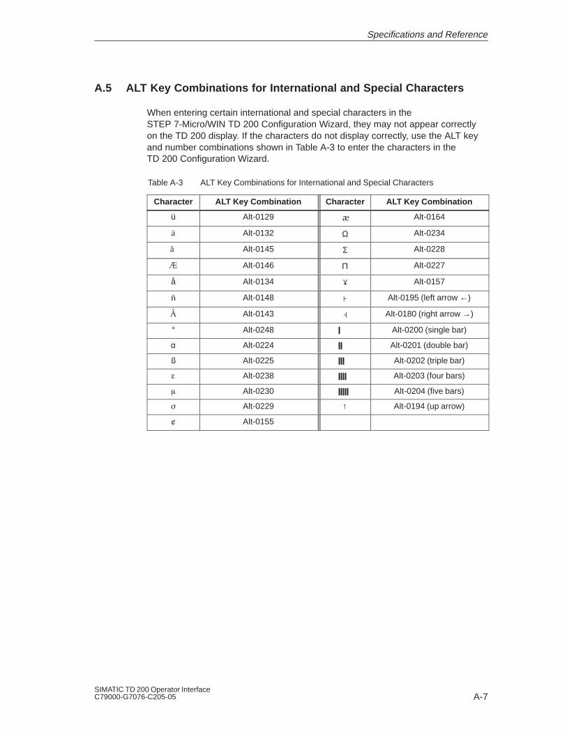
A-7SIMATIC TD 200 Operator InterfaceC79000-G7076-C205-05
A.5 ALT Key Combinations for International and Special Characters
When entering certain international and special characters in theSTEP 7-Micro/WIN TD 200 Configuration Wizard, they may not appear correctlyon the TD 200 display. If the characters do not display correctly, use the ALT keyand number combinations shown in Table A-3 to enter the characters in theTD 200 Configuration Wizard.
Table A-3 ALT Key Combinations for International and Special Characters
Character ALT Key Combination Character ALT Key Combination
ü Alt-0129 Alt-0164
Alt-0132 Ω Alt-0234
Alt-0145 Σ Alt-0228
Alt-0146 Π Alt-0227
å Alt-0134 Alt-0157
Alt-0148 Alt-0195 (left arrow ←)
Alt-0143 Alt-0180 (right arrow →)
° Alt-0248 Alt-0200 (single bar)
α Alt-0224 Alt-0201 (double bar)
Alt-0225 Alt-0202 (triple bar)
Alt-0238 Alt-0203 (four bars)
Alt-0230 Alt-0204 (five bars)
Alt-0229 ↑ Alt-0194 (up arrow)
Alt-0155
Specifications and Reference

A-8SIMATIC TD 200 Operator Interface
C79000-G7076-C205-05
Specifications and Reference

B-1SIMATIC TD 200 Operator InterfaceC79000-G7076-C205-05
Multiple CPU Configurations
This appendix explains how to connect multiple TD 200s and S7-200 CPUstogether on one communication network. The TD 200s act as network masters anddo not interfere with one another. The CPUs can be either masters or slaves onthe network.
Chapter Overview
Section Description Page
B.1 Configuring for Multiple CPU Communication B-2
B.2 Building a TD/CPU Cable B-4
B
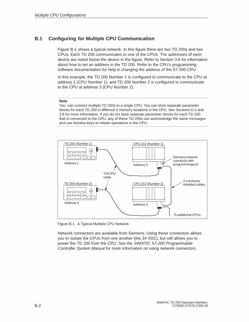
B-2SIMATIC TD 200 Operator Interface
C79000-G7076-C205-05
B.1 Configuring for Multiple CPU Communication
Figure B-1 shows a typical network. In this figure there are two TD 200s and twoCPUs. Each TD 200 communicates to one of the CPUs. The addresses of eachdevice are noted below the device in the figure. Refer to Section 3.8 for informationabout how to set an address in the TD 200. Refer to the CPU’s programmingsoftware documentation for help in changing the address of the S7-200 CPU.
In this example, the TD 200 Number 1 is configured to communicate to the CPU ataddress 2 (CPU Number 1), and TD 200 Number 2 is configured to communicateto the CPU at address 3 (CPU Number 2).
NoteYou can connect multiple TD 200s to a single CPU. You can store separate parameterblocks for each TD 200 in different V memory locations in the CPU. See Sections D.1 and3.8 for more information. If you do not store separate parameter blocks for each TD 200that is connected to the CPU, any of these TD 200s can acknowledge the same messagesand use function keys to initiate operations in the CPU.
TD 200 (Number 1) CPU 212 (Number 1)
TD 200 (Number 2) CPU 212 (Number 2)
Address 1
Address 4
Address 2
Address 3
To additional CPUs
2-conductorshielded cables
Siemens networkconnector withprogramming port
TD/CPUcable
Figure B-1 A Typical Multiple CPU Network
Network connectors are available from Siemens. Using these connectors allowsyou to isolate the CPUs from one another (the 24 VDC), but still allows you topower the TD 200 from the CPU. See the SIMATIC S7-200 ProgrammableController System Manual for more information on using network connectors.
Multiple CPU Configurations

B-3SIMATIC TD 200 Operator InterfaceC79000-G7076-C205-05
WarningThe CPUs provide 24 VDC on the communication connector to power devices such as theTD 200.
You must not connect the 24 VDC lines between CPUs. Doing so could result in damageto the CPUs.
You must only connect communication lines (pins 3, 5, and 8), not power lines (pins 2and 7), when networking CPUs.
NoteWhen you connect a PG 702 to a network of CPUs and TD 200s, the PG 702 does notfunction if there are more than three TD 200s.
NoteThe display update time slows as more TD 200s are added to the network.
Multiple CPU Configurations
!

B-4SIMATIC TD 200 Operator Interface
C79000-G7076-C205-05
B.2 Building a TD/CPU Cable
The TD/CPU cable is used for connecting a display device to an S7-200 CPU. Ifyou do not have a TD/CPU cable, refer to Figures B-2 and B-3 to create your owncable.
Making a Cable That Supplies Power to the TD 200
Figure B-2 shows you the pin-out of TD/CPU cable with power supplied to theTD 200. Use this option when you want the TD 200 to receive power from anS7-200 CPU.
NC24 VDC Return
Transmit/Receive Data +
NC
Logic Ground
NC24 VDC
Transmit/Receive Data –
NC
24 VDC Return
Transmit/Receive Data +
Logic Ground
24 VDC
Transmit/Receive Data –
Shield
12
3
4
5
67
8
9
12
3
4
5
67
8
9
TD 200 Side S7-200 Side
Figure B-2 TD/CPU Cable with Power Connections
Making a Cable That Does Not Supply Power to the TD 200
Figure B-3 shows you the pin-out of a TD/CPU cable without power supplied to theTD 200. Use this option when you want the TD 200 to receive power from anexternal power supply. The maximum length for the cable is 1200 meters.
Transmit/Receive Data +
Logic Ground
Transmit/Receive Data –
Transmit/Receive Data +
Logic Ground
Transmit/Receive Data –
Shield
12
3
4
5
67
8
9
12
3
4
5
67
8
9
TD 200 Side S7-200 Side
Figure B-3 TD/CPU Cable without Power Connections
Multiple CPU Configurations

C-1SIMATIC TD 200 Operator InterfaceC79000-G7076-C205-05
Troubleshooting
Refer to Table C-1 for a list of the problems that could occur with the TD 200 andpossible causes and solutions.
Table C-1 Troubleshooting Table
Problem Possible Cause Solution
NO PARAMETER BLOCK The TD 200 could not find aparameter block in theprogrammable logic controller.
Configure a parameter block forthe TD 200 in the programmablelogic controller. Refer to Chapter 2.
Be sure the parameter blockaddress in the TD 200 matchesthe actual address of theparameter block. Refer to Section 3.8.
The TD 200 found a parameterblock in the programmable logic
t ll b t it t i
Be sure all fields are withinrange.
controller, but it contains errors.Be sure all addresses are legalfor the CPU. Refer to Section D.2.
CPU NOT RESPONDING Address of the CPU is incorrect. Correct the address errors. Referto Section 3.8.
CPU does not have power. Power up the CPU.
Cable problems. Check the cable connections.
Wrong baudrate configured. Correct the baud rateconfiguration. Refer to Section 3.8.
Multiple CPUs at the sameaddress.
Remove other CPUs and retry.
May need network terminations. See SIMATIC S7-200Programmable Controller SystemManual.
Network too long or too manydevices on network.
See SIMATIC S7-200Programmable Controller SystemManual.
HARDWARE ERROR TD 200 is inoperable. The TD 200 module could bedefective. Replace with a newmodule.
C

C
C-2SIMATIC TD 200 Operator Interface
C79000-G7076-C205-05
Table C-1 Troubleshooting Table
Problem SolutionPossible Cause
NETWORK ERROR(TD 200 cannot establish a
t k ti t
May be multiple masters with thesame address.
Remove other masters and retry.
network connection or enter anexisting network.)
Cable problems. Check the cable connections.existing network.)
Multiple CPUs at the sameaddress.
Remove other CPUs and retry.
CPU BUSY Some other master has lockedthe CPU by uploading ordownloading a program to thatCPU.
Wait — it disappears in a fewseconds.
CPU IN STOP MODE RUN/STOP switch is in STOP. Put CPU in RUN mode.
Troubleshooting

D-1SIMATIC TD 200 Operator InterfaceC79000-G7076-C205-05
TD 200 Parameters and Messages
Software Support for Configuring a TD 200
Some programming packages include a configuration utility for entering theparameter block and messages for the TD 200. For example, version 1.2.1 ofSTEP 7-Micro/DOS uses Utility 24 for configuring the TD 200. STEP 7-Micro/WINprovides a “wizard” that makes it easy to configure the parameter block and themessages in the data memory area of the S7-200 CPU (see Chapter 2). Refer toyour programming software and its documentation to determine whether itsupports a TD 200 configuration utility.
Chapter Overview
Section Description Page
D.1 TD 200 Parameter Block D-2
D.2 Building the Parameter Block D-4
D.3 Formatting Messages D-9
D.4 Embedding Data Values in a Text Message D-11
D.5 Understanding Message Types D-20
D.6 Editing Variables with the TD 200 D-22
D

D-2SIMATIC TD 200 Operator Interface
C79000-G7076-C205-05
D.1 TD 200 Parameter Block
Understanding How Messages Are Displayed
The messages that the TD 200 displays are stored in the CPU. These messagescontain ASCII text, embedded values, and format information. The CPU enablesthe messages through the use of a table of message-enable bits. There must beone message bit allocated in V memory for each configured message. When theprogram in the CPU says to display a message, the program sets that particularmessage-enable bit. The TD 200 continuously polls the message-enable bits, andif one of the bits is set, the TD 200 reads the corresponding message from theCPU and writes the message to the display.
Understanding How the TD 200 Uses the Parameter Block
A TD 200 parameter block contains the TD 200 configuration information, andmust be created in the data memory (V memory) area of the S7-200 CPU in orderto establish an interface between the CPU and the TD 200. The TD 200 monitorsthe CPU for either a parameter block identifier (ASCII characters “TD”) or an offsetto the parameter block.
If the TD 200 does not find the parameter block identifier (“TD”) in VW0, it uses thevalue stored in VW0 as an offset to the TD 200 parameter block (see example inSection 2.1). When the parameter block identifier is found, the next 8 or 10 bytesprovide the TD 200 with configuration information.
You can change the V memory address for the parameter block by means of asetup menu. (See Section 3.8.) This allows you to connect two TD 200 units to oneCPU, with each TD 200 displaying different messages. Figure D-1 shows twoTD 200s connected to a single CPU. The parameter blocks for each of the TD 200are stored in different V memory locations.
SIEMENS TD 200
SIMATICS7-200
SIEMENS TD 200
TD 200 Unit 1Parameter block at VW0
V Memory
TD 200 Unit 2Parameter block at VW40
VW0 Parameter blockfor unit 1
VW40 Parameter blockfor unit 2
Figure D-1 Displaying Different Messages on Two TD 200 Units
TD 200 Parameters and Messages

D-3SIMATIC TD 200 Operator InterfaceC79000-G7076-C205-05
The default location of the parameter block is VW0, but you can store theparameter block (or the offset to the parameter block) in any V memory locationbetween VW0 and VW999. (Use the Setup menu to change the location of theparameter block. See Section 3.8.) If you change the location of the parameterblock, the TD 200 looks to that location for either the parameter block or the offsetto the parameter block.
If the parameter block identifier cannot be found, the error messageNO PARAMETER BLOCK is displayed. The TD 200 continues to monitor VW0 (orthe V memory location entered by means of the Setup menu) for either a validparameter block ID or an offset to a parameter block with a valid parameter blockID.
NoteThe TD 200 defaults to address 1 and attempts to communicate to a CPU at address 2.See Section 3.8 to change the network addresses if other addresses are used.
Description of the Parameter Block Format
The parameter block consists of 10 or 12 bytes of memory which define the modesof operation and point to the location in CPU memory where the actual messagesare stored, as shown in Figure D-2. When you power up the TD 200, it looks for aparameter block identifier in the CPU at VW0, either the ASCII characters “TD” oran offset to the parameter block location, and it reads the data contained in theblock.
Byte 0 Byte 1 Byte 2 Byte 3 Byte 4 Byte 5 Byte 6 Byte 7 Byte 8 Byte 9
ParameterBlock ID
TD 200Configuration
No. ofMsgs.
M AreaAddress
MessageAddress
MessageEnable
Address
Language DisplayUpdate Rate
Display Mode:20 or 40 characters per message
Disable/Enable Force Function
Disable/Enable Time-of-Day Clock Menu
CPU Memory
“T” “D”
Select Standard orAlternate (Bar Graph)character set
Disable/Enable Edit Password.Note: If enabled, password is stored in bytes 10 and 11of extended parameter block.
Points to messages
A L L L U U U U 0 P C F D
Byte 10 Byte 11
Password(optional)
7 6 5 4 3 2 1 0 7 6 5 4 3 2 1 0
Figure D-2 TD 200 Parameter Block
TD 200 Parameters and Messages

D-4SIMATIC TD 200 Operator Interface
C79000-G7076-C205-05
D.2 Building the Parameter Block
Parameter Block ID Bytes 0 and 1
The TD 200 monitors the CPU for messages. To display the messages, it must firstlocate the parameter block that contains the block ID information “TD”. The TD 200parameter block is identified by two bytes; byte 0 must be the ASCII character “T”and byte 1 must be the ASCII character “D”.
TD 200 Configuration Bytes 2 and 3
Byte 2 of the TD 200 parameter block allows you to configure the desired languageand the update time. Figure D-3 shows the information contained in Byte 2 of theparameter block.
(L) Language The language selection determines the display language of theTD 200 menus.
(U) Update Rate The update rate selection determines how often the TD 200polls the S7-200 CPU for messages to display. The actual update time may beslower depending on the size of the message and the processing required.
(A) Alternate Character Set The character set selection enables the use ofan alternate character set designed for displaying bar charts on the TD 200.See Appendix A.
A L L U U U U7 6 5 4 3 2 1 0
MSB LSB
TD 200 Configuration
Byte 2 Byte 3
LSB ofConfig.
L - Language*0 - Not defined 4 - Italian1 - English 5 - Spanish2 - German 6 - Not defined3 - French 7 - Not defined
U - Display Update Rate*0 - As fast as possible 8 - 8 seconds1 - Every 1 second 9 - 92 - 2 seconds A - 103 - 3 B - 114 - 4 C - 125 - 5 D - 136 - 6 E - 147 - 7 F - 15
* Values given as hexadecimal values
MSB ofConfig.
0 1 4 5 6 7 8 9 10 11
A - Alternate character set0 - Standard character set1 - Alternate character set
Figure D-3 Information Contained in Byte 2 of the TD 200 Parameter Block
TD 200 Parameters and Messages

D-5SIMATIC TD 200 Operator InterfaceC79000-G7076-C205-05
Byte 3 of the TD 200 parameter block allows you to enable the Time-of-Day (TOD)and Force menus, to select either 20- or 40-character display mode, and/or toenable password protection (before allowing any editing). It also contains bitswhich are set when either the UP or DOWN arrow keys are pressed.
(C) TOD Clock and (F) Force The TOD Clock and Force selections allow youto selectively enable the TOD Clock menu and/or the Force menu. Once eitheris enabled, you are allowed to access that function in the TD 200. If the functionis not enabled, it does not appear in the TD 200 Menu mode.
(D) Display Mode The display mode selection allows you to choose whetherdisplay messages are one line (20 characters) or two lines (40 characters).
(P) Edit Password The edit password selection allows you to enable afour-digit password (using 0000-9999) to authorize an operator to edit variablesembedded in a message. The password itself is stored in bytes 10 and 11 ofthe parameter block.
(UA and DA) Up Arrow and Down Arrow The up/down arrow status bitsallow your program additional control of the TD 200 display. The TD 200 setsthese bits in the controller if you press these keys while the TD 200 is in displaymode, assuming there is no more than one message active. If your programuses these bits, the program must reset these bits after they are used.
Figure D-4 shows the information contained in Byte 3.
D - Display Mode0 - 20 characters per message1 - 40 characters per message
F - Force Function0 - Disable the force function menu1 - Enable the force function menu
C - TOD Clock Menu0 - Disable the TOD
clock menu1 - Enable the TOD
clock menu
*Note: Values are given in hexadecimal values.
MSB ofConfig.
TD 200 Configuration
Byte 2 Byte 3
LSB ofConfig.
0 C F UA DA 0 D7 6 5 4 3 2 1 0
MSB LSB
0 1 4 5 6 7 8 9
P - Edit Password0 - disable1 - enable
DA- Down arrow key0 - Key was not pressed1 - Key was pressed
UA - Up arrow key0 - Key was not pressed1 - Key was pressed
10 11
Figure D-4 Information Contained in Byte 3 of the TD 200 Parameter Block
Number of Messages Byte 4
Byte 4 of the TD 200 parameter block defines the number of messages you haveconfigured. The TD 200 accepts values 0 to 80.
TD 200 Parameters and Messages

D-6SIMATIC TD 200 Operator Interface
C79000-G7076-C205-05
Prioritizing Messages
To ensure that you receive the most important message first, the TD 200 uses afixed priority scheme. In this scheme, a higher priority message displaces a lowerpriority message. There is one message-enable bit for each message. Therefore,you can have from 0 to 80 message-enable bits corresponding to the number ofmessages. You must not use message-enable bits for any other purpose otherthan enabling messages. The TD 200 requires that you allocate full bytes formessage-enable bits.
Messages are numbered in ascending order starting with message 1. Message 1is located at the message address specified by configuration bytes 6 and 7 of theTD 200 parameter block. Byte 0 of the message-enable bits is located at themessage-enable address specified by configuration bytes 8 and 9 of the TD 200parameter block. The highest priority message is message 1 and the lowest prioritymessage is message 80. See Section D.5 for more information on messagepriorities and the display of messages.
Figure D-5 shows the prioritization scheme and the correspondence betweenmessage-enable bits and messages.
Byte 0Byte 1Byte 2Byte 3Byte 4Byte 5Byte 6Byte 7Byte 8Byte 9
Message 1 - Priority 1 - (Highest)7 6 5 4 3 2 1 0
9 10 11 12 13 14 15 161725334149576573
1826344250586674
1927354351596775
2028364452606876
2129374553616977
2230384654627078
2331394755637179
2432404856647280
MSB LSB
1 2 3 4 5 6 7 8
Message 80 - Priority 80 - (Lowest)
Figure D-5 Message-Enable Bits for up to 80 Messages
M Area Address Byte 5
You must reserve eight bits of marker memory (M bits) for the TD 200 to use whena function key is pressed. Your program can inspect these bits and take theappropriate action when a key is pressed. One M bit is set by the TD 200 eachtime the corresponding function key is pressed.
NoteThe TD 200 does not automatically reset the function-key M bits after they are set. If youuse these bits within your program, you must then reset them from within your program.
Byte 5 of the TD 200 parameter block defines the address of the byte of M bits.Valid address values for specific CPUs are defined in the SIMATIC S7-200Programmable Controller System Manual.
TD 200 Parameters and Messages

D-7SIMATIC TD 200 Operator InterfaceC79000-G7076-C205-05
Figure D-6 shows a referenced byte (MBn) and shows which bit of the byte is setby each function key.
WarningThe TD 200 sets an M bit each time a function key is pressed. If you do not intend to usefunction keys, and therefore do not assign an M byte address for function keys, the TD 200defaults to byte M0 for the function keys. If your program uses bits in M0, and a userpresses any function key, the TD 200 sets the corresponding bit in M0, overwriting thevalue assigned to that bit by your program.
Inadvertent changes to M bits could cause your program to behave unexpectedly.Unpredictable controller operation could cause death or serious injury to personnel, and/ordamage to equipment.
Always reserve an M area address, even when your program does not utilize functionkeys.
M Area Address
F4 F3 F2 F1ShiftF4
ShiftF3
ShiftF2
ShiftF1MBn
MSB7 6 5 4 3 2 1
LSB0
1 2 4 6 7 8 9Byte 5
MOffset
30
Figure D-6 Bits Set by Each Function Key
Message Address Bytes 6 and 7
Bytes 6 and 7 of the TD 200 parameter block define an integer-word offset inV memory where the TD 200 looks for the first message. Valid offset values forspecific CPUs are defined in the SIMATIC S7-200 Programmable ControllerSystem Manual.
NoteEach 20-character message uses 20 VB memory locations; each 40-character messageuses 40 VB memory locations.
Message-Enable Address Bytes 8 and 9
Bytes 8 and 9 of the TD 200 parameter block define the integer-word offset in Vmemory where the TD 200 looks for the first byte of the message-enable bits. Validoffset values for specific CPUs are defined in the SIMATIC S7-200 ProgrammableController System Manual.
For example: if you assign VB50 as the message-enable address, the firstmessage is enabled by bit V50.7, the second message by V50.6, the thirdmessage by V50.5, and the eighth message by V50.0.
TD 200 Parameters and Messages
!
D-8SIMATIC TD 200 Operator Interface
C79000-G7076-C205-05
You must not use message-enable bits for any purpose other than enablingmessages. The TD 200 requires that you allocate full bytes for message-enablebits.
NoteYou can set or clear the message-enable bits from within your program. The TD 200 mayalso clear the message-enable bit following an acknowledge or an edit. See Section D.6for more information.
Edit Password Byte 10 and 11 (Optional)
Bytes 10 and 11 of the TD 200 parameter block store a password that allows youto edit the configuration of the TD 200 or to change variables. This password is afour-digit integer (from 0000 to 9999). Byte 3 of the parameter block enables thepassword protection. If you enable the password protection by setting thepassword bit in byte 3, you must enter a password in bytes 10 and 11; however, ifyou do not enable password protection in byte 3, you are not required to store apassword in bytes 10 and 11.
TD 200 Parameters and Messages

D-9SIMATIC TD 200 Operator InterfaceC79000-G7076-C205-05
D.3 Formatting Messages
Messages can contain multiple text fields, format words, and variables. TheTD 200 allows two message sizes.
20-character message mode - displays two messages at a time
40-character message mode - displays one message at a time
Once you choose a message size, all messages must correspond to that size. Thesize is selected on a system basis in the parameter block, and not on aper-message basis. The TD 200 uses the setting of the message size to index themessages stored in the S7-200 CPU V memory.
In applications where alarm or fault conditions can occur and notification isessential, you can configure the TD 200 to display multiple messages.
This section shows you how to create a 20- or 40-character message.
NoteA message cannot have more than six variables. Additional variables are ignored and thevariable positions in the display remain blank.
Twenty-Character Message Format
The 20-character message format requires 20 bytes of V memory storage in theS7-200 CPU for each message. Each message is displayed on one line of theTD 200 display, allowing two messages to be shown at the same time. Figure D-7shows an example of how a 20-character message can be formatted in the CPUand displayed on the TD 200.
P R E S S U R E f f Value P S I
P R E S S U R E 1 2 3 4 P S I
Text 1 FormatWord
VariableData (word)
Text 2
How the Message Looks in V Memory
How the Message Is Displayed on the TD 200
Figure D-7 Twenty-Character Message Format
TD 200 Parameters and Messages

D-10SIMATIC TD 200 Operator Interface
C79000-G7076-C205-05
Forty-Character Message Format
The 40-character message format requires 40 bytes of V memory storage in theS7-200 CPU for each message. Each message requires both lines of the TD 200display, allowing only one message to be shown at a time. Figure D-8 shows anexample of how a 40-character message can be formatted in the CPU anddisplayed on the TD 200.
P R E S S U R E P S If f Value
Text 1
FormatWord
VariableData
(word) Text 2
How the Message Looks in V Memory
P 1 = f f m P 2 = m mf Valuem
P R E S S U R E P S I1 2 3
Text 3
P 1 = 1 2 3 4 m P 2 = 7 m m5 6m
How the Message Is Displayed on the TD 200
4
f
FormatWord
VariableData
(word)
Text 4 FormatWord
VariableData
(word)
Text 5
Value
Figure D-8 Forty-Character Message Format
TD 200 Parameters and Messages

D-11SIMATIC TD 200 Operator InterfaceC79000-G7076-C205-05
D.4 Embedding Data Values in a Text Message
The TD 200 allows you to place data values within the message that you want todisplay. You can display and edit these embedded values. Each embedded valuemust be preceded by a format word which defines how the value is displayed andwhether the message requires acknowledgement.
Data Value Format Options
The format word in a message provides the following information:
How the value is displayed-signed or unsigned; word, double word, or real(floating-point); and decimal position
Whether or not the message requires acknowledgement
Whether the optional data value is editable
Whether editing requires a password
You can use format words alone, with an optional word value, with an optionaldouble word value, or with an optional real (floating-point) value. The format worduses two bytes of your message if it is not followed by a data value, four bytes ofyour message if the format word is followed by a word value, and six bytes of yourmessage if the format word is followed by a double word value or a real(floating-point) value. Figure D-9 shows each type of format word usage.
Byte 0 Byte 1
MSB ofFormat
LSB ofFormat
Byte 0 Byte 1
MSB ofFormat
LSB ofFormat
Byte 2 Byte 3
MSB ofWord
LSB ofWord
Byte 0 Byte 1
MSB ofFormat
LSB ofFormat
Byte 2 Byte 3
MSB ofDWord
Byte 4 Byte 5
LSB ofDWord
Format Word without an Optional Data Value
Format Word with an Optional Word Value
Format Word with an Optional Double Word Value or Real (Floating-Point) Value
NOTE: This allows you to configure a message foracknowledgement (to be flashing), but to have no datato display.
Figure D-9 Format Word Usage
TD 200 Parameters and Messages

D-12SIMATIC TD 200 Operator Interface
C79000-G7076-C205-05
Defining the Data Value Format
Figure D-10 shows the bit values of Byte 0 and Byte 1 of the format word. Byte 0uses only five bits (bits 0 through 4). Byte 1 uses only six bits (bits 0, 1, 2, and 4,5, 6). All other bits of the byte (for both Byte 0 and Byte 1) must be set to zero.
Format Word Optional Data Value
Byte 0 Byte 1 Byte 2 Byte 3 Byte 4 Byte 5
MSB ofFormat
LSB ofFormat
MSB ofData
LSB ofData
0 0 E P EN A
7 6 5 4 3 2 1 0MSB LSB
AN
E - Edit Allowed
EN - Edit-Notification
A - Acknowledgement
AN - Acknowledgement-Notification
P - Password Protected
0
Format Word Optional Data Value
Byte 0 Byte 1 Byte 2 Byte 3 Byte 4 Byte 5
MSB ofFormat
LSB ofFormat
MSB ofData
LSB ofData
S S 0 D D7 6 5 4 3 2 1 0
MSB LSB
D
D - Placement of the Decimal PointS - Data Size/Format
Byte 0
Byte 1
Figure D-10Bit Values of the Format Word
Do not use non-printable characters in your message text: the TD 200 uses thesecharacters to identify the start of a format word. The non-printable characters areASCII codes 0 to 31 (0 to 1F hexadecimal).
Acknowledgement Bit 0
To ensure that important messages are displayed and acknowledged by anoperator, you can program a message to require acknowledgement. You do this bysetting the acknowledgement bit in the most significant byte of the format word.Figure D-11 shows the placement of the acknowledgement bit in byte 0 of theformat word.
A - Acknowledgement0 - No acknowledgement1 - Acknowledgement required
Format Word Optional Data Value
Byte 0 Byte 1 Byte 2 Byte 3 Byte 4 Byte 5
MSB ofFormat
LSB ofFormat
MSB ofData
LSB ofData
0 0 E P EN A7 6 5 4 3 2 1 0
MSB LSB
AN
Figure D-11 Acknowledgement Bit of Byte 0 of the Format Word
TD 200 Parameters and Messages
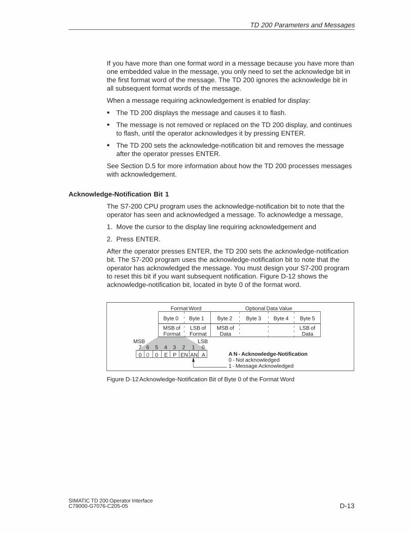
D-13SIMATIC TD 200 Operator InterfaceC79000-G7076-C205-05
If you have more than one format word in a message because you have more thanone embedded value in the message, you only need to set the acknowledge bit inthe first format word of the message. The TD 200 ignores the acknowledge bit inall subsequent format words of the message.
When a message requiring acknowledgement is enabled for display:
The TD 200 displays the message and causes it to flash.
The message is not removed or replaced on the TD 200 display, and continuesto flash, until the operator acknowledges it by pressing ENTER.
The TD 200 sets the acknowledge-notification bit and removes the messageafter the operator presses ENTER.
See Section D.5 for more information about how the TD 200 processes messageswith acknowledgement.
Acknowledge-Notification Bit 1
The S7-200 CPU program uses the acknowledge-notification bit to note that theoperator has seen and acknowledged a message. To acknowledge a message,
1. Move the cursor to the display line requiring acknowledgement and
2. Press ENTER.
After the operator presses ENTER, the TD 200 sets the acknowledge-notificationbit. The S7-200 program uses the acknowledge-notification bit to note that theoperator has acknowledged the message. You must design your S7-200 programto reset this bit if you want subsequent notification. Figure D-12 shows theacknowledge-notification bit, located in byte 0 of the format word.
A N - Acknowledge-Notification0 - Not acknowledged1 - Message Acknowledged
Format Word Optional Data Value
Byte 0 Byte 1 Byte 2 Byte 3 Byte 4 Byte 5
MSB ofFormat
LSB ofFormat
MSB ofData
LSB ofData
0 0 E P EN A7 6 5 4 3 2 1 0
MSB LSB
AN
Figure D-12Acknowledge-Notification Bit of Byte 0 of the Format Word
TD 200 Parameters and Messages

D-14SIMATIC TD 200 Operator Interface
C79000-G7076-C205-05
You can design your S7-200 program to take other actions as a result of setting theacknowledge-notification bit. Figure D-13 shows how you can use theacknowledge-notification bit. For this example, VB21 is assumed to be the mostsignificant byte of the first format word of the message.
Ladder Logic Statement List
// Resetting the acknowledge-notification // bit and using it to enable the next// message
LD V21.1 // When the operator acknowledges the R V21.1,1 // message, reset the bit and enable
// the next message MOVB . . . // Move ...
Network #
MOV_BEN
OUT . . .. . . IN
V21.1 V21.1 1
R
Figure D-13Sample Program for Using the Acknowledge-Notification Bit
Edit-Notification Bit 2
The TD 200 sets the edit-notification bit to 1 after an edit. The CPU can read thisedit-notification bit value to recognize when an editable data value has beenchanged. The program can then read and make use of the edited value.
NoteThe edit-notification bit does not reset automatically when subsequent edits are performed.If you want the TD 200 to detect and notify you of a second edit operation, you mustdesign your program to reset the edit-notification bit to zero. Figure D-14 shows theplacement of the edit-notification bit, located in byte 0 of the format word.
EN- Edit-Notification0 - Not edited1 - Message edited
Format Word Optional Data Value
Byte 0 Byte 1 Byte 2 Byte 3 Byte 4 Byte 5
MSB ofFormat
LSB ofFormat
MSB ofData
LSB ofData
0 0 E P EN A7 6 5 4 3 2 1 0
MSB LSB
AN
Figure D-14Edit-Notification Bit of Byte 0 of the Format Word
If an embedded value is set to allow editing, you must design your S7-200 programto check the edit-notification bit. When the embedded value is modified by theuser, your program must read the value and take any necessary action with it.
TD 200 Parameters and Messages

D-15SIMATIC TD 200 Operator InterfaceC79000-G7076-C205-05
CautionThe edited (new) value that the user enters in an embedded message can be overwrittenby the value that was displayed in the message before the edit.
This could cause you to lose the newly edited value.
If you allow an embedded value to be edited, you must design your program to check theedit-notification bit and to move and/or save the edited (new) value each time there is anedit.
If a value is set to allow editing, you can move the cursor to the embedded valueand increment or decrement the value by using the UP and DOWN arrows. TheSHIFT-UP/DOWN arrow keys allow you to move to specific characters within thevariable. The longer you press the arrow key, the faster the value changes.
After you have changed the embedded value to the desired value, you must pressENTER. Pressing ENTER causes the TD 200 to send the edited value to theS7-200 CPU and sets the edit-notification bit in the format word preceding theembedded value.
Figure D-15 shows an example of how you can use the edit-notification bit. For thisexample, VB21 is assumed to be the most significant byte of the first format wordof the message, and the embedded value is a word-sized value immediatelyfollowing the format word (located in VW23).
Ladder Logic Statement List
//Using the edit-notification bit to copy // the edited value, and then resetting // the notification bit. //
LD V21.2 // When the operator edits the embedded R V21.2, 1 // value, reset the bit and copy the edited MOVWVW23,VW250 // value to the variable location.
// LD SM0.0 // On each scan ...MOVWVW250,VW23 // copy the variable to the location of the
// embedded value.SM 0.0 MOV_W
EN
OUT VW23VW250 IN
Network #
MOV_WEN
OUT VW250VW23 IN
V21.2 V21.2 1
R
Network #
Figure D-15Sample Program for Using the Edit-Notification Bit
TD 200 Parameters and Messages
!

D-16SIMATIC TD 200 Operator Interface
C79000-G7076-C205-05
Password Protection Bit 3
Setting bit 3 in byte 0 of the format word (see Figure D-16) enables you to requirethat a password be entered before allowing a variable to be edited from theTD 200. This password (a four-digit integer from 0000 to 9999) is stored in bytes10 and 11 of the parameter block.
P - Password Protection0 - Password not enabled1 - Password enabled
Format Word Optional Data Value
Byte 0 Byte 1 Byte 2 Byte 3 Byte 4 Byte 5
MSB ofFormat
LSB ofFormat
MSB ofData
LSB ofData
0 0 E P EN A7 6 5 4 3 2 1 0
MSB LSB
AN
Figure D-16Password Protection Bit of Byte 0 of the Format Word
Edit-Allowed Bit 4
Figure D-17 shows the edit-allowed bit that is used by the TD 200 to determinewhether or not you can edit a data value. If the edit-allowed bit is set, the TD 200sets the edit-notification bit (bit 2 in byte 0 of the format word) after you haveedited the data value.
E - Edit-Allowed0 - Edit not allowed1 - Edit allowed
Format Word Optional Data Value
Byte 0 Byte 1 Byte 2 Byte 3 Byte 4 Byte 5
MSB ofFormat
LSB ofFormat
MSB ofData
LSB ofData
0 0 E P EN A7 6 5 4 3 2 1 0
MSB LSB
AN
Figure D-17Edit-Allowed Bit of Byte 0 of the Format Word
TD 200 Parameters and Messages

D-17SIMATIC TD 200 Operator InterfaceC79000-G7076-C205-05
Data Size/Format, and Decimal Bits 0, 1, 2 and 4, 5, 6
The least significant byte of the format word is used to specify the size, the format,and the position of the decimal point in a displayed value. The selection of signedor unsigned affects the editing range of a value. Unsigned values are restricted topositive numbers. Signed values can be either positive or negative. Figure D-18shows the placement of the data size/format and decimal point bits in byte 1 of theformat word.
Unsigned words have a range from 0 to 32,767
Signed words have a range from -32,768 to 32,767
Unsigned double words have a range from 0 to 2,147,483,647
Signed double words have a range from -2,147,483,648 to 2,147,483,647
Real (floating-point) numbers have a range from 1.7549*10-38 to3.40282*1038.
NoteDue to the size of the display, the TD 200 can display real numbers between 1*10-7 and9.99999*1019. Values smaller than 1*10-7 are displayed as “0”, and values larger than9.99999*1019 are displayed as “eeeeee”.
D- Placement of the Decimal Point0 - No decimal point1 - One digit to the right of the decimal point2 - Two digits to the right of the decimal point3 - Three digits to the right of the decimal point4 - Four digits to the right of the decimal point5 - Five digits to the right of the decimal point6 - Six digits to the right of the decimal point7 - Seven digits to the right of the decimal point
S- Data Size/Format0 - No data value1 - Signed word value2 - Signed double word value3 - Unsigned word value4 - Unsigned double word value5 - Real (floating-point) value6 - Reserved7 - Reserved
Format Word Optional Data Value
Byte 0 Byte 1 Byte 2 Byte 3 Byte 4 Byte 5
MSB ofFormat
LSB ofFormat
MSB ofData
LSB ofData
0 S S 0 D D7 6 5 4 3 2 1 0
MSB LSB
D
Figure D-18Bit Values of Byte 1 of the Format Word
TD 200 Parameters and Messages

D-18SIMATIC TD 200 Operator Interface
C79000-G7076-C205-05
The TD 200 displays all values as decimal numbers. Various types of data aredisplayed in the following manner:
Positive signed values are displayed without a sign.
Negative signed values are displayed with a leading minus sign.
Unsigned values are displayed without a sign.
Values without non-zero digits to the left of the decimal point are displayed witha leading zero on the left side of the decimal point.
Real (floating point) numbers are displayed with the number of decimal placesthat you specified (see Figure D-18). The value is rounded to the designatedlevel of precision. For example, if one decimal place were specified for thevalue 12.567, the TD 200 would display “12.6”.
TD 200 Parameters and Messages

D-19SIMATIC TD 200 Operator InterfaceC79000-G7076-C205-05
The number of display characters that are used to display a value varies. Thisvariation is not reflected in the number of bytes that are required to store the valuein the S7-200 CPU memory. In the CPU memory, two bytes are required to store aword value, and four bytes are required to store a double word or a real (floatingpoint) value.
Table D-1 shows you how many display characters are required for each displayformat and the maximum number of display characters required for each format.For example, if you know that the size of the value will never exceed three digitsand will always be positive, then the number of display characters required willalways be less than the maximum values given in Table D-1.
For real (floating point) numbers, the TD 200 uses up to 20 digits to represent thenumber. (This includes the number of decimal places that were specified in theformat word. See Figure D-18.) If a number cannot be displayed within the numberof digits available, the TD 200 displays “eeeeee” for that value.
Table D-1 Required Display Characters for Each Display Format
Value Size
Number ofDigits to theRight of the
Decimal Point
Number of DisplayCharacters(maximum)
Example
0 5 12345
1 to 4 6 1234.5 to 1.2345
Unsigned Word 5 7 0.12345g
6 8 0.012345
7 9 0.0012345
0 6 -12345
1 to 4 7 -1234.5 to -1.2345
Signed Word 5 8 -0.12345g
6 9 -0.012345
7 10 -0.0012345
0 10 1234567891
Unsigned DWord1 to 7 11
123456789.1 to123.4567891
0 11 -1234567891
Signed DWord1 to 7 12
-123456789.1 to-123.4567891
Real 0 Up to 20 -1234567Real(FloatingPoint)
DWord1 to 7 Up to 20
12345.6 to0.0123456
TD 200 Parameters and Messages
D-20SIMATIC TD 200 Operator Interface
C79000-G7076-C205-05
D.5 Understanding Message Types
Every message falls into one of four possible message acknowledgement andediting types. This section explains specifically how each message type is handledby the TD 200. The four message types follow:
No acknowledgement required. No edits allowed.
Acknowledgement required. No edits allowed.
No acknowledgement required. Edits allowed.
Acknowledgement required. Edits allowed.
No Acknowledgement, No Edits Allowed
In this combination of no acknowledgement required and no edits allowed, theTD 200 simply displays the message. The ENTER key has no function since thereare no editable variables within the message. The message can contain variablesthat are updated at the update rate of the TD 200. This type of message isreplaced on the display if a higher priority message is enabled by the S7-200 CPU.The operator can either press the UP or the DOWN arrow key to scroll throughother messages or press ESC to return to the Menu mode.
The TD 200 does not clear the corresponding message-enable bit in the S7-200CPU.
Acknowledgement, No Edits Allowed
In this combination of acknowledgement required and no edits allowed, the TD 200displays the message and makes the entire message flash (blink) until the operatorpresses ENTER to acknowledge the message. Variable values are updated fromthe S7-200 CPU at the normal update rate while the message is flashing.
When the operator presses ENTER, the TD 200:
Sets the acknowledgement-notification bit in the first format byte of themessage.
Clears the message-enable bit for this particular message. This causes themessage to be removed from the display on the next update cycle.
Another message cannot replace the one flashing until the operator acknowledgesthe flashing message. This is also true even if a higher priority message is enabledin the S7-200 CPU. If the TD 200 is configured for 20-character messages and theCPU enables a higher priority message, the flashing message shifts to the secondline of the display. The operator cannot press the UP or the DOWN key to scrollthrough other enabled messages until s/he acknowledges the current message.
TD 200 Parameters and Messages

D-21SIMATIC TD 200 Operator InterfaceC79000-G7076-C205-05
No Acknowledgement, Edits Allowed
In this combination of no acknowledgement required and edits allowed, the TD 200displays a message and then waits for the operator to edit it. All of the variableswithin the message are updated at the update rate. Since the message does notrequire acknowledgement, this type of message is removed from the TD 200display if a higher priority message is enabled in the S7-200 CPU. An up or downarrow in the right-most character position indicates more messages. The operatorcan press either the UP or the DOWN arrow key to scroll through the otherenabled messages.
For more information about editing variables, see Section D.6.
Acknowledgement, Edits Allowed
In this combination of acknowledgement required and edits allowed, the TD 200displays the message, causes the entire message to flash (blink), and then waitsuntil the operator acknowledges the message and edits the variables. Thiscombination requires that the operator edit the variables. If the operator attemptsto exit before editing all the variables in the message, the message flashes toindicate that edits are pending.
When the message is enabled in the S7-200 CPU, the TD 200 notes this and, ifthere is space available on the display, gets the message from the CPU. TheTD 200 then displays the message and causes the entire message to flash tonotify the operator that the message is present and must be acknowledged.
For more information about editing variables, see Section D.6.
TD 200 Parameters and Messages

D-22SIMATIC TD 200 Operator Interface
C79000-G7076-C205-05
D.6 Editing Variables with the TD 200
You can use the TD 200 to modify variables embedded in the messages. You canalso configure a message to require that an operator acknowledge the message(see Section D.5). Messages that must be acknowledged flash when displayed onthe TD 200. The operator uses the arrow keys and the ENTER key toacknowledge messages and to edit variables.
NoteDue to restrictions in the format used to store real (floating-point) numbers in both theS7-200 CPU and the TD 200, the accuracy of the number is limited to six significant digits.Editing a real number with more than six digits may not change the value of the variable, ormay cause other digits within the number to change:
Changing the least significant (right-most) digit of a real-number variable withmore than six digits may have no effect. For example: if you try to change the“9” in “1234.56789”, the value of the variable does not change.
Changing the most significant (left-most) digit of a real-number variable withmore than six digits may cause other (less significant) digits in the variable tochange.
Acknowledging and Editing a Message
Use the following procedure to edit a variable:
1. If the message does not require acknowledgement (is not flashing), select themessage by pressing either the UP or the DOWN arrow key to place the cursoron the first character of the desired message.
2. Press ENTER to move the cursor to the least significant (right-most) characterof the first editable variable.
For messages that require acknowledgement, pressing ENTER also sets theacknowledge-notification bit in the CPU and halts the flashing of the messageon the display.
3. If the variable is password-protected, enter the 4-digit password at the promptand press ENTER.
4. Press either the UP or the DOWN arrow key to increment or decrement thevariable. (Pressing and holding either the UP or the DOWN key accelerates theincrement or decrement operation.)
– To move the cursor to the next digit position, press either the SHIFT UP(left) or the SHIFT DOWN (right) keys.
– To reset the variable to 0, press the SHIFT ENTER keys.
5. Press ENTER to write the updated variable to the CPU.
On the same program scan, the edit-notification bit is set in the format wordcorresponding to the variable being edited.
TD 200 Parameters and Messages
D-23SIMATIC TD 200 Operator InterfaceC79000-G7076-C205-05
If there are more editable variables in the message, the cursor moves to the nextvariable. After all of the variables in the message have been edited, themessage-enable bit for the message is cleared in the CPU. The message is thenremoved from the display on the next update cycle.
If you do not edit the message variable, or if you abort the edit by pressing ESC,the message-enable bit is not cleared by the TD 200. The message-enable bit iscleared by the TD 200 only when you write the last editable variable to the CPU.
The UP and DOWN arrows that indicate higher and lower priority messages, if anyare present, are disabled while an edit is in progress. These functions are restoredwhen the edit is completed or aborted.
Aborting an Edit
You can abort an edit at any time by pressing ESC. This causes the TD 200 toreread the message from the CPU and to display the variables from the CPU.When the edit session is aborted, any values that have already been sent to theCPU (by pressing the ENTER key after modifying the value) are displayed; anyvalue that was modified but not saved is overwritten by the previous (original)value.
When you abort an edit, the cursor returns to the left-most character of themessage. (The message is not removed from the display until all of the edits arecompleted and written to the CPU.) If the message was configured foracknowledgement, the message starts to flash again, since the edit was notcompleted.
NoteAn edit is automatically aborted if you do not press a key after one minute.
TD 200 Parameters and Messages

D-24SIMATIC TD 200 Operator Interface
C79000-G7076-C205-05
TD 200 Parameters and Messages

Index-1SIMATIC TD 200 Operator InterfaceC79000-G7076-C205-05
IndexAAcknowledge message
not required, D-20, D-21required, 2-16, D-20, D-21
Acknowledge-notification bit, D-13Acknowledgement bit, D-12Acknowledging messages, D-22–D-24Address, network, setting, 3-16Arrow keystrokes, recorded in the parameter
block, D-5ASCII character set, A-7ASCII characters, TD 200 display, A-7
BBar graph character set, 2-4, 4-5, D-4
ALT key combinations, A-8ASCII characters, A-7
CCable, TD/CPU, creating a pin-out, B-4Clock, enabling, 2-5, D-5Command keys, description, 1-3Communication
multiple CPUs, 1-6, B-1one-to-one, 1-6
Communication connections, 1-6Configuration
messages, 2-7–2-11multiple CPUs, B-1one-to-one, 1-6parameter block, D-4
Configuration Wizard, D-1introduction, 2-2
CPU address, selecting, 3-17
DData size/format bits, D-17–D-20Data value
acknowledge-notification bit, D-13acknowledgement bit, D-12
data size/format bits, D-17–D-20decimal (scaled) display, 2-12decimal bits, D-17–D-20edit-notification bit, D-14editing, D-16embedding in text messages, D-11format word, D-11real numbers, D-17–D-20
Date, setting, 3-13Decimal bits, D-17–D-20Defining messages, 2-9, D-9Display message mode, 3-2Display update rate, 2-5
selecting, 2-5Displaying different messages, 3-18, D-2
EEdit, aborting, 3-4Edit allowed, messages, D-21Edit not allowed, messages, D-20Edit value bit, D-16Edit-notification bit, D-14Editing variables, 3-3–3-5, D-22–D-24
configuring password protection, 2-5, D-5enabling a password, D-16releasing the password, 3-15storing a password, D-8
Embedded data, 2-16, D-11dialog box, 2-12
Embedded data values (text messages), for-matting, 2-12, D-11–D-19
Embedded variables, acknowledging andediting, 3-3–3-5, D-22–D-24
Error messagesfatal, 3-8non-fatal, 3-8viewing, 3-7
FFloating point numbers. See Real numbersForce function, 2-5
enabling, 2-5, D-5

Index-2SIMATIC TD 200 Operator Interface
C79000-G7076-C205-05
Force I/O menu, 3-9accessing, 3-9changing status, 3-12correcting a password, 3-10entering a password, 3-10options, 3-11
Format worddata value, D-11password protection, D-16
Function keys, 1-3description, 1-3enabling, 2-5specifying memory bits, 2-5
HHardware features, 1-2
II/O
changing force status, 3-12forcing/unforcing, 3-9, 3-12
Installation, TD 200, 1-4International characters, A-8
ALT key combinations, A-8
KKeyboard, 1-3
LLadder editor, 2-20, 4-4, 4-6Language, operator interface, 2-4, D-4
MM area address, parameter block, 2-5, D-6Manuals, iv
finding topics in manual set, ivMenu language, 2-4Menu mode, 3-5
force I/O, 3-9release password, 3-15set time and date, 3-13Setup menu
baud rate, 3-19CPU network address, 3-17
parameter (V memory) address, 3-18TD 200 network address, 3-16
TD 200 Setup Menu, 3-16–3-20viewing CPU status, 3-7viewing messages, 3-6
Message address, parameter block, D-7Message enable address, parameter block,
D-8Message enable flags, 2-8Message format
20-character, D-940-character, D-9size, D-9
Messages, 2-7–2-11acknowledge and edit, D-21acknowledge, no edits, D-20acknowledgement required, 2-16acknowledgement required, edits al-
lowed, D-21creating, 2-9data values in text, 2-10defining, 2-9embedded data, 2-16, D-11embedding data values, 2-10, D-11enable flags, 2-8, D-8formatting embedded data value, 2-12,
D-11location, 2-8no acknowledgement, edits allowed,
D-21no acknowledgement, no edits, D-20number of, D-5prioritizing, D-6size/number, 2-7text-only, 2-9viewing, 3-6viewing errors, 3-7
Mode of operationdisplay message, 3-2menu, 3-5
Mounting, TD 200, 1-4
NNetwork address, setting, 3-16Number of messages, parameter block, D-5
Index

Index-3SIMATIC TD 200 Operator InterfaceC79000-G7076-C205-05
OOperating mode
display message mode, 3-2menu mode, 3-5
PParameter block, D-2
20-character message format, D-940-character message format, D-9address, 2-8description, D-2display mode configuration, D-5Force function configuration, D-5M area address, 2-5, D-6message address, D-7message enable address, D-8message size, D-9multiple, 3-18, D-2number of messages, D-5password protection, D-5recording up/down arrows in, D-5sample, 2-19saving/viewing, 2-19TD 200 configuration, D-4TOD clock configuration, D-5V memory location of, 3-18, D-2
Passwordcorrecting, 3-10enabling password protection, 2-5entering, 3-10
Password protection, 2-5configuring the parameter block, 2-5, D-5enabling a password, D-16releasing the password, 3-15storing a password, D-8
Pin-out, TD/CPU cable, B-4Power
external supply, 1-7TD/CPU cable, 1-7
Program, samplegenerating a bar graph, 4-5using text message to create a clock for
CPU 214, 4-2
Programmable logic controller. See S7–200CPU
RReal numbers, D-17–D-20
editing variables in a message, 3-3, D-22Related manuals, iv
finding topics in manual set, iv
SS7–200 CPU, 1-1Scaled display of data, 2-12Set time and date menu, 3-13Special characters, A-8
ALT key combinations, A-8Statement List editor, 2-20, 4-6STEP 7–Micro/WIN, 2-2
TD 200 Configuration Wizard, 2-2, 4-2
TTD 200, defined, 1-1TD 200 Configuration Wizard
introduction, 2-2starting, 2-2
TD 200 Setup menu, 3-16–3-20TD/CPU cable, creating a pin-out, B-4Technische Daten, TD 200, A-4Text Display 200. See TD 200Time, setting, 3-13Time-of-Day (TOD) menu, enabling, 2-5Troubleshooting, TD 200, C-1
VV memory, storing different parameter
blocks in, 3-18, D-2Variable data, editing, 3-3, D-22Variables, acknowledging and editing,
3-3–3-5, D-22–D-24Viewing CPU status menu, 3-7Viewing messages menu, 3-6
Index

Index-4SIMATIC TD 200 Operator Interface
C79000-G7076-C205-05
Index

SIMATIC TD 200 Operator Interface6ES7272-0AA00-8BA0-05 1
Siemens AG
A&D AS E 81
Oestliche Rheinbrueckenstr. 50
D-76181 Karlsruhe
Federal Republic of Germany
Please check any industry that applies to you:
Automotive
Chemical
Electrical Machinery
Food
Instrument and Control
Nonelectrical Machinery
Petrochemical
Pharmaceutical
Plastic
Pulp and Paper
Textiles
Transportation
Other _ _ _ _ _ _ _ _ _ _ _
From:
Your Name: _ _ _ _ _ _ _ _ _ _ _ _ _ _ _ _ _ _ _ _ _ _ _ _ _ _ _ _ _
Your Title: _ _ _ _ _ _ _ _ _ _ _ _ _ _ _ _ _ _ _ _ _ _ _ _ _ _ _ _ _
Company Name: _ _ _ _ _ _ _ _ _ _ _ _ _ _ _ _ _ _ _ _ _ _ _ _ _ _
Street: _ _ _ _ _ _ _ _ _ _ _ _ _ _ _ _ _ _ _ _ _ _ _ _ _ _
City, Zip Code _ _ _ _ _ _ _ _ _ _ _ _ _ _ _ _ _ _ _ _ _ _ _ _ _ _
Country: _ _ _ _ _ _ _ _ _ _ _ _ _ _ _ _ _ _ _ _ _ _ _ _ _ _
Phone: _ _ _ _ _ _ _ _ _ _ _ _ _ _ _ _ _ _ _ _ _ _ _ _ _ _

2SIMATIC TD 200 Operator Interface
6ES7272-0AA00-8BA0-05
Additional comments:
_ _ _ _ _ _ _ _ _ _ _ _ _ _ _ _ _ _ _ _ _ _ _ _ _ _ _ _ _ _ _ _ _ _ _ _ _ _ _ _
_ _ _ _ _ _ _ _ _ _ _ _ _ _ _ _ _ _ _ _ _ _ _ _ _ _ _ _ _ _ _ _ _ _ _ _ _ _ _ _
_ _ _ _ _ _ _ _ _ _ _ _ _ _ _ _ _ _ _ _ _ _ _ _ _ _ _ _ _ _ _ _ _ _ _ _ _ _ _ _
_ _ _ _ _ _ _ _ _ _ _ _ _ _ _ _ _ _ _ _ _ _ _ _ _ _ _ _ _ _ _ _ _ _ _ _ _ _ _ _
_ _ _ _ _ _ _ _ _ _ _ _ _ _ _ _ _ _ _ _ _ _ _ _ _ _ _ _ _ _ _ _ _ _ _ _ _ _ _ _
_ _ _ _ _ _ _ _ _ _ _ _ _ _ _ _ _ _ _ _ _ _ _ _ _ _ _ _ _ _ _ _ _ _ _ _ _ _ _ _
_ _ _ _ _ _ _ _ _ _ _ _ _ _ _ _ _ _ _ _ _ _ _ _ _ _ _ _ _ _ _ _ _ _ _ _ _ _ _ _
_ _ _ _ _ _ _ _ _ _ _ _ _ _ _ _ _ _ _ _ _ _ _ _ _ _ _ _ _ _ _ _ _ _ _ _ _ _ _ _
_ _ _ _ _ _ _ _ _ _ _ _ _ _ _ _ _ _ _ _ _ _ _ _ _ _ _ _ _ _ _ _ _ _ _ _ _ _ _ _
_ _ _ _ _ _ _ _ _ _ _ _ _ _ _ _ _ _ _ _ _ _ _ _ _ _ _ _ _ _ _ _ _ _ _ _ _ _ _ _
_ _ _ _ _ _ _ _ _ _ _ _ _ _ _ _ _ _ _ _ _ _ _ _ _ _ _ _ _ _ _ _ _ _ _ _ _ _ _ _
_ _ _ _ _ _ _ _ _ _ _ _ _ _ _ _ _ _ _ _ _ _ _ _ _ _ _ _ _ _ _ _ _ _ _ _ _ _ _ _
Remarks Form
Your comments and recommendations will help us to improve the quality and usefulness of ourpublications. Please take the first available opportunity to fill out this questionnaire and return itto Siemens.
Please give each of the following questions your own personal mark within the range from 1 (verygood) to 5 (poor).
1. Do the contents meet your requirements?
2. Is the information you need easy to find?
3. Is the text easy to understand?
4. Does the level of technical detail meet your requirements?
5. Please rate the quality of the graphics/tables: