td-107™ oil content monitor imo mepc 107(49)-certifiedtd107.com/td107 operation manual.pdf ·...
TRANSCRIPT

Operation Manual
TD-107™ Oil Content Monitor IMO MEPC 107(49)-Certified
February 15, 2009 P/N NAG2501 REV A Global Sales & Service Support: Naval Automation Group (NAG) Marine 2511 Walmer Avenue Norfolk, VA 23513 +1 757 852 3998 www.nagmarine.com

TD-107™ Oil Content Monitor Operation Manual
2
THIS PAGE INTENTIONALLY LEFT BLANK
TD-107™ Oil Content Monitor Operation Manual
3
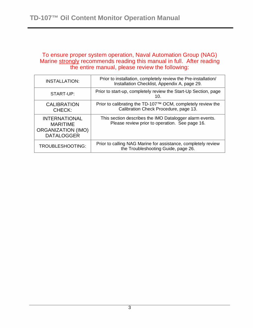
To ensure proper system operation, Naval Automation Group (NAG) Marine strongly recommends reading this manual in full. After reading
the entire manual, please review the following:
INSTALLATION: Prior to installation, completely review the Pre-installation/ Installation Checklist, Appendix A, page 29.
START-UP: Prior to start-up, completely review the Start-Up Section, page 10.
CALIBRATION CHECK:
Prior to calibrating the TD-107™ OCM, completely review the Calibration Check Procedure, page 13.
INTERNATIONAL MARITIME
ORGANIZATION (IMO) DATALOGGER
This section describes the IMO Datalogger alarm events. Please review prior to operation. See page 16.
TROUBLESHOOTING: Prior to calling NAG Marine for assistance, completely review the Troubleshooting Guide, page 26.

TD-107™ Oil Content Monitor Operation Manual
4
TABLE OF CONTENTS
1.0. INTRODUCTION.............................. 6
2.0. THEORY OF OPERATION .............. 6
2.1. Light Source ......................... 6
2.2. Excitation Filter ..................... 6
2.3. Sample Cell .......................... 6
2.4. Emission Filter ...................... 7
2.5. Light Detector ....................... 7
3.0. SPECIFICATIONS ........................... 8
4.0. INSTALLATION ............................... 8
4.1. Pre-Installation/Installation ......... 8 4.2. Power & Utility Requirements..... 8 4.3. Required Tools & Accessories.... 9 4.4. Location & Sampling Point ......... 9 4.5. Mechanical Connections ............ 9 4.6. Electrical Connections.............. 10
5.0. START-UP ..................................... 10
5.1. Start-Up Procedure .................. 10 6.0. FLUORESCENCE CALIBRATION CHECK ................................................. 13
6.1. Fluorescence Calibration Check Procedure ....................................... 13
6.2. Calibration Data Screen ........... 13 7.0. CELL CONDITION CALIBRATION ..................................... 14 7.1. Cell Condition Calibration Procedure ....................................... 14
7.2. Notes on Cell Condition Calibrating....................................... 14
8.0. IMO DATALOGGER …….……… ...16 8.1. IMO Datalogger Data Retrieval. 16 8.2. EVENTS.txt Example ............... 18 9.0. PREVENTATIVE MAINTENANCE . 19
9.1. Cleaning Flow-cell .................... 19 9.2. Desiccant Plug Replacement.... 20 9.3. Calibration ................................ 20 9.4. Replacement Parts................... 20
10.0. INTERNAL ALARMS ................... 21
10.1. Internal Alarm Delay............... 21 10.2. Internal Alarm Activation ........ 21 10.3. Multiple Internal Alarms.......... 21 10.4. Internal Alarm History............. 21 10.5. Notes About Alarms ............... 21
10.6. System Function Alarms Definitions....................................... 22 10.7. Function Alarm Definitions ..... 22
11.0. TROUBLESHOOTING ................. 24
11.1. Diagnostics ............................ 24 11.2. IMO Datalogger Failure .......... 25 11.3. Service Assistance................. 25 11.4. Troubleshooting Guide ........... 26
12.0. RESPONSIBILITY FOR SAFE DELIVERY............................................ 28
APPENDICIES
A: INSTALLATION CHECKLIST ........... 29
B: CONFIGURATION RECORD........... 31
C: TD-107™ OCM CONTROL FUNCTIONS......................................... 32
D: TD-107™ OCM SOFTWARE FUNCTIONS......................................... 34
E: SCREEN FLOW CHARTS................ 35
F: SYSTEM, CLOCK, AND ALARM VALUES ............................................... 37
G: TD-107™ OCM TROUBLESHOOTING WORKSHEET....................................... 39
FIGURES & DIAGRAMS ...................... 41
Figure (1) Front View ...................... 41 Figure (2) Bottom View ................... 42 Figure (3) Left View......................... 43 Figure (4) Right View ...................... 44 Figure (5) Back View....................... 45 Figure (6) Wiring Schedule.............. 46 INDEX .................................................. 47
TD-107™ Oil Content Monitor Operation Manual
5
TABLES Table 1. 15ppm Check Solution Values ........................................................ 11 Table 2. Calibration Data................. 13 Table 3. System Function Alarms.... 21 Table 4. Function Alarms................. 22 Table 5. System Default Values and Ranges..................................... 37
TD-107™ Oil Content Monitor Operation Manual
6
1.0. INTRODUCTION
IMPROPER INSTALLATION, USE, APPLICATION OR UNAUTHORIZED SERVICING OF THIS EQUIPMENT VOIDS ALL WARRANTIES.
CAUTION: The TD-107™ must be installed, operated, and maintained according to this manual to remain in compliance with IMO regulations. Any activities regarding the TD-107™ other than described here may jeopardize compliance with IMO regulations and may be documented by the TD-107™.
CAUTION: Failure to install, operate, and maintain the TD-107™ Oil Content Monitor according to these directions may cause oil discharges in violation of IMO regulations. All directions in this manual must be followed exactly to remain in compliance.
CAUTION: High concentrations (greater than 100 ppm oil content) can cause false readings and may cause accidental discharge of high oil content water. This monitor is to be used in conjunction with a 15 ppm certified bilge separation system. We suggest a latch system on the vessel’s diverter valve and an independent analysis to determine recovery from extreme upset conditions.
The TD-107™ Oil Content Monitor (OCM) detects hydrocarbons in water using fluorescence in combination with a proprietary flow-cell. The TD-107™ OCM is able to activate discharge control devices to divert bilge water discharge, and permits process monitoring through system-function alarm contacts, oil content alarm contacts, and analog sample concentration outputs. Compared with other oil content detection technologies such as turbidity and light scatter, the TD-107™ OCM offers:
1. High resistance to false alarms due to suspended solids.
2. High selectivity, by “targeted hydrocarbon” optical tuning, minimizing chemical interferences.
3. Low maintenance due to the flow-
cell condition monitor.
2.0. THEORY OF OPERATION
TD-107™ OCM measures the oil content via fluorescence. Fluorescent hydrocarbons absorb light at one wavelength and emit light at a longer wavelength. Fluorometers contain five important components: 1. Light Source 2. Excitation Filter 3. Sample Cell 4. Emission Filter 5. Light Detector 2.1. Light Source The TD-107™ OCM light source emits photons over a broad wavelength range. The photons from this light source pass through an Excitation Filter, which reduces the range of wavelengths illuminating the oil in water flowing through the Sample Cell. 2.2. Excitation Filter The range of wavelengths transmitted through the Excitation Filter is selected by the factory to excite the “targeted hydrocarbon” and minimize the impact of other constituents in the water. 2.3. Sample Cell While flowing through the Sample Cell, the “target hydrocarbon” and possibly other constituents in the water absorb the excitation light and emit longer wavelength light called “fluorescence light”.
TD-107™ Oil Content Monitor Operation Manual
7
2.4. Emission Filter The emitted light passes through an emission filter, which narrows the range of wavelengths reaching the detector. The range of wavelengths transmitted through the emission filter is selected by the factory to optimize “targeted hydrocarbon” response while meeting IMO MEPC 107(49) performance regulations. 2.5. Light Detector When a photon reaches the Light Detector, a pulse of electricity is produced. The TD-107™ OCM counts these pulses to determine the “targeted hydrocarbon” concentration in the water passing through the Flow-cell.
TD-107™ Oil Content Monitor Operation Manual
8
3.0. SPECIFICATIONS
NAG MARINE Part Number: NAG2500
• Power: 20-240 VAC/VDC, 50/60 Hz, 15 watts
• Dry Contact Alarm Relays (5), including 15 ppm alarm, 240 VAC or 28 VDC, 6 A maximum. Normally open and normally closed connections.
• System Status Inputs (2), continuity or 3–28 VDC, 10 mA minimum, 100 mA maximum
• Signal Output: One internally-powered 4–20 mA (isolated), (0 - 30 ppm).
• USB (2.0) port for retrieving data files. • Dimensions: 14.625 in. W x 6.6875 in.
D x 12 in. H [371.5 mm W x 169.9 mm D x 304.8 mm H]
• Weight: 12 lbs. [5.4 kg] • Enclosure: Approximates NEMA 4 • Maximum Sample Pressure: 100 psig
[689.5 kPa(g)] • Inlet Valve Pipe Size: 0.25 in. [6.35
mm] FNPT • Outlet Pipe Size: 0.25 in. [6.35 mm]
Swagelok® tube fitting • Ambient Temperature: 40-120 °F [4–49
°C] • Maximum Sample Temperature: 140 °F
[71 °C] • Relative Humidity: 0–100 %
4.0. INSTALLATION
4.1. Pre-Installation/Installation
CAUTION: Do not break the provided tamper evident IMO certification seals for any reason. Breaking such seals will invalidate the IMO certification of the monitor.
The pre-installation/installation checklist found in Appendix A provides important guidelines and information to aid in preparing for installation.
4.2. Power & Utility Requirements
See Figure (7) on page 45 of the manual for details.
4.2.1. Power: 20-240 VAC, 50/60 Hz, 15 watts. Power must be connected to the monitor at all times. 4.2.2. Bilge Separator Status This input requires either continuity or a 3–28 VDC, min 10 mA, max 100 mA signal to indicate the Bilge Separator System is operational. This input is required and is recorded in the IMO Datalogger. 4.2.3. Sample Flow Status This input requires either continuity or a 3–28 VDC, min 10 mA, max 100 mA signal to indicate the Bilge Water is flowing through the Bilge Separation System. This input is required and is recorded in the TD-107™. 4.2.4. High Signal Alarm Relay (15.0 ppm) to Vessel’s Diverter Valve A Normally Open (NO) and Normally Closed (NC) dry contact is provided. Relay contact rating: 240 VAC or 28 VDC, 6 A. This output is required and is recorded in TD-107™. This output must be connected to the vessel’s diverter valve. 4.2.5. Early Warning Alarm Relay A NO and NC dry contact is provided. Relay contact rating: 240 VAC or 28 VDC, 6 A. This alarm relay activates if the recorded ppm value is 10.0 or greater. This output is optional but is recorded in the TD-107™. 4.2.6. Zero Signal Alarm Relay A NO and NC dry contact is provided. Relay contact rating: 240 VAC or 28 VDC, 6 A. This alarm relay activates if the recorded value is 0.00 ppm or less. This output is optional but is recorded in the TD-107™.
TD-107™ Oil Content Monitor Operation Manual
9
4.2.7. System Alarm Relay A NO and NC dry contact is provided. Relay contact rating: 240 VAC or 28 VDC, 6 A. This alarm relay activates if the TD-107™ OCM has an internal system alarm event. This output is optional but is recorded in the TD-107™. 4.2.8. Cell Condition Alarm Relay A NO and NC dry contact is provided. Relay contact rating: 240 VAC or 28 VDC, 6 amps. This alarm relay activates if the TD-107™ OCM requires the flow-cell to be cleaned based upon the user defined Cell Condition Threshold value (30–90 %). 4.2.9. Signal Output One internally-powered 4–20 mA signal (isolated), 0.0–30.0 ppm. 4.2.10. USB The port must be accessible for data retrieval. 4.2.11. Recirculating Water Sample Supplied to oil content monitor at 0.13 U.S. gal/min [0.5 L/min] minimum, 1.0 U.S. gal/min (3.78L/min) maximum and less than 100 psig [689.5 kPa(g)]. The recommended maximum sample tubing diameter and length are 0.25 in. [6.35 mm] x 25 ft [7.62 m].
NOTE: Higher flow rates may require more frequent cleaning of the Flow-cell.
4.2.12. Drain/Outlet
Sample outlet from the TD-107™ OCM should be piped to either an atmospheric drain with no back pressure or a pressurized system. Atmospheric drains must have the drain pipes terminate below the unit. Pressurized system discharge must create sufficient pressure drops to create flow through the instrument. Do not combine the discharge from other devices to the TD-107™ OCM discharge. In installations where this is not feasible, contact NAG Marine for assistance.
4.3. Required Tools & Accessories
• Standard plumbing and electrical tools are required for installation.
• NAG Marine recommends that stainless steel flexible tubing be used on the inlet and outlet connections. This will facilitate future maintenance needs and prevent damage to the monitor due to transmitted vibration and/or pipe strain.
• IMO Certified Oily Water Separator system including diverter valve.
4.4. Location & Sampling Point
The sampling point should be located such that the sample approximates the bulk oil concentrations of the treated bilge water, is homogeneous and free of all entrained air.
It is extremely important to eliminate air entrapment in the sample line. The best way to accomplish this is to sample from the center of the pipe or from the side of the pipe.
The recommended maximum sample tubing diameter and length are 0.25 in. [6.35 mm] x 25 ft [7.62 m].
The unit should not be installed adjacent to known heat sources or in direct sunlight; this could cause the internal temperature of the unit to be significantly higher than ambient temperature and produce errors or damage the components.
Do not install within 10 feet [3.048 m] of devices such as large generators or transformers, which generate a strong electromagnetic field; cooling water recirculating pumps are not a problem.
NOTE: The maximum environment temperature is specified at 120 °F [49 °C].
4.5. Mechanical Connections

TD-107™ Oil Content Monitor Operation Manual
10
Refer to Figures (1) and (2) respectively for the location of the required mechanical connections. The TD-107™ OCM must be mounted to a vertical surface with the mounting tabs. The mounting tabs accept a maximum 0.375 in. [9.53 mm] diameter bolt.
Two 0.25 in. [6.35 mm] connections are provided for pipe hook-up. The sample inlet line is 0.25 in. [6.35 mm] FNPT; the sample outlet line is 0.25 in. [6.35 mm] Swagelok® tube fitting. The optional vent connection is a 0.25 in. [6.35 mm] Swagelok® tube fitting.
CAUTION: The outlet plumbing connections MUST NOT place stress on the 0.25 in. [6.35 mm] tube drain connection point. Damage to the instrument may occur if plumbed incorrectly.
NOTE: Pipe rises greater than 10 ft [3.048 m] should be avoided. In installations where this is not feasible, contact NAG Marine for further assistance.
NOTE: Mounting the unit at eye level is recommended.
4.6. Electrical Connections Only trained personnel should make electrical connections.
Refer to Figure (7) for the "Terminal Connections", showing the pre-wired cabling for the Inputs/Outputs required of the power, alarm outputs, process status inputs, and 4–20 mA connections.
NOTE: The 4–20 mA output is internally powered and internally shielded. DO NOT connect customer end of shield to ground.
CAUTION: Do not break the provided tamper evident IMO certification seals for
any reason. Breaking such seals will invalidate the IMO certification of the monitor.
To connect a wire to the pre-wired cabling:
1. Turn off main power to the instrument at the breaker.
2. Verify all process inputs and switched outputs are off.
3. Terminate the wire cabling as mandated by shipboard requirements in junction boxes.
To disconnect a wire from the pre-wired cabling:
1. Turn off main power to the instrument at the breaker.
2. Verify all process inputs and switched outputs are off.
3. Access the junction box to disconnect the wire.
NOTE: Signal wires and power wiring should not be run in the same conduit. Failure to separate or shield these wires will result in electrical interference.
5.0. START-UP
The TD-107™ OCM (P/N NAG2500) includes the following components: • TD-107™ OCM Instrument
Assembly • Accessory Kit: P/N NAG2502 • Operation Manual: P/N NAG2501
Information & components supplied by the user:
• IMO Certified Oily Water Separator with Diverter Valve
These items are not included with the TD-107™ OCM but should be obtained before start-up:
• Clean De-Ionized (DI) Water

TD-107™ Oil Content Monitor Operation Manual
11
If necessary, please contact your NAG Marine representative or contact NAG Marine at +1 757 852 3998 for additional information.
5.1. Start-Up Procedure
NOTE: A diagram of the screens is located in Appendix E. Perform the following steps to start the TD-107™ OCM:
1. Bring sample flow to and from the TD-107™ OCM; check for leaks in plumbing.
2. Depress the Main Power Switch on the left hand face to power the TD-107™ OCM (see Figure (1)).
NOTE: When power is first turned on, an identification screen will appear for a few seconds, showing the software version and date. After 10 seconds (press <ENT> or <HOME> for immediate access), the HOME screen will appear. The HOME screen will display the oil content, the bilge water temperature, and the Cell Condition %.
XX.X PPM T: XXC Cell: XX%
Sample HOME Screen
If the screen appears blank or dark, try adjusting the screen contrast using the UP [�] and DOWN [�] AROWS.
NOTE: The user must return to the HOME screen (by pressing either the <HOME> or <ESC> key) after verifying each value. Jumping between screens without returning to the HOME screen is not permitted.
3. During start-up, verify the following settings:
<0> HIGH STANDARD VALUE AND LOW STANDARD VALUE
• This value relates the fluorescence measurement standard to a reference oil content fluorescence measurement. The value is printed on the label of the calibration solution and listed in Table
1. The value is programmed into the TD-107 and cannot be changed.
• Press <0><1> to display the High Standard calibration solution value.
• Press <0><2> to display the Low Standard calibration solution value.
Table 1. Check Solution Values
Solution Concentration Value
Part Number
15.0 ppm NAG2503*
0.0 ppm (DI Water)
Customer Supplied
* 1.0 L Container
<1> HIGH SIGNAL ALARM CONCENTRATION
The high signal alarm relay is factory set at 15.0 ppm and cannot be changed.
• Press <1> to display the programmed value.
<2> EARLY WARNING ALARM CONCENTRATION
The early warning alarm indicates possible Oily Water Separator (OWS) maintenance requirements or process upset conditions. The early warning alarm level is set at 10.0 ppm and cannot be changed.
• Press <2> to display the programmed value.
<3> ZERO SIGNAL ALARM CONCENTRATION
The zero signal alarm concentration indicates possible OWS maintenance conditions or bypassing with clean water. The zero signal alarm level is set at 0.0 ppm and cannot be changed.
• Press <3> to display the programmed value.
<4> 4 mA OUTPUT

TD-107™ Oil Content Monitor Operation Manual
12
The 4 mA output is factory set at 0.0 ppm and connected to the IMO Datalogger. It cannot be changed.
• Press <4> to display the programmed value.
<5> MASTER ID
For security, an End-User ID is required to change the cell condition threshold, cell delay, and calibrate the cell condition system. The original or default value is 0258. To change the End-User ID, contact your NAG Marine representative for assistance with the Master ID.
• Press <5>. • Key in Master ID. • Press <ENT>. • Key in new End-User ID. • Press <ENT>. • Press <HOME>. NOTE: The Master ID and End-User ID will intentionally not allow access to features of the monitor which would compromise its application performance or data storage. <6> 20 mA OUTPUT
The 20 mA output is factory set to 30.0 ppm and connected to the IMO Datalogger. It cannot be changed.
• Press <6> to display the programmed value.
NOTE: During an internal alarm condition, the 4–20 mA output will still transmit the oil content concentration.
<7> CELL THRESHOLD
This value determines the specific flow-cell transmission degradation for activating the Cell Condition Alarm. The range of user definable values is 30 to 90 % which are selectable in 10 % increments.
NOTE: Cell condition alarms at 30 % or below will also report to the monitor’s
System alarm since cleaning is required to meet IMO measurement tolerances.
• Press <7>. • Press <ENT>. Before entering /
changing the value, the monitor will prompt for the End-User ID. Enter a valid End-User ID (default is 0258) and then <ENT>.
• Key in new Cell Threshold by pressing <ENT> until the appropriate value appears.
• Press <HOME>.
<8> CELL DELAY
This value determines the time interval delay for activating the Cell Condition Alarm. The cell delay is activated when the Cell Threshold % value is exceeded (lower value) for the Cell Delay period.
NOTE: This delay does not affect the System Alarm when the System Alarm is due to an excessively fouled flow-cell.
• Press <8>. • Press <ENT>. Before entering /
changing the value, the monitor will prompt for the End-User ID. Enter a valid End-User ID (default is 0258) and then <ENT>.
• Key in new Cell Delay by pressing <ENT> until the appropriate value appears.
• Press <HOME>.
NOTE: The date and time are set in the TD-107™ OCM to Greenwich Mean Time (GMT) and cannot be changed.
The TD-107™ OCM start-up is now complete.
NOTE: After start-up, wait a minimum of 15 minutes before operating to allow the unit to come to equilibrium.

TD-107™ Oil Content Monitor Operation Manual
13
6.0. FLUORESCENCE CALIBRATION CHECK
6.1. Fluorescence Calibration Check Procedure
Refer to Figure (1) for locations of items. A diagram of display screens is located in Appendix E.
Perform the following steps to check the Fluorescence Calibration:
1. Move the inlet Valve 1 to the maintenance position. A Maintenance Alarm event will be recorded by the IMO Datalogger. Confirm discharge piping is not pressurized. If the monitor is equipped with optional outlet Valve 2, move Valve 2 to the vent position.
2. Clean unit by injecting cleaning solution with a syringe into the flow-cell. The syringe screws onto the Luer-Lok™ fitting on the inlet valve (see Figure (1)). Fill syringe with 60 mL of cleaning solution. Screw syringe onto fitting. Inject cleaning solution at a slow, steady rate into flow-cell and allow to stand for 3–5 minutes. Using a clean 60 mL syringe, flush flow-cell thoroughly with 60 mL of clean water.
NOTE: A syringe is provided in the TD-107™ OCM Accessory Kit (NAG MARINE P/N NAG2502).
3. Using the syringe for the clean water, flush the flow-cell with 60 mL of clean water via the Luer-Lok™ Injection Port. Then inject a second 60 mL syringe of clean water and allow it to remain in the flow-cell by leaving the syringe attached. Note the HOME screen reading for the clean water. Although unlikely, note that variations up to ± 5 ppm are allowed.
0.100 PPM
T: 23C Cell: 100%
Example HOME screen
NOTE: Bubbles trapped during injection are a possible source of instrument error. With the syringe in a vertical position, tap against a solid object to move bubbles to
the needle end of the syringe. Then, force bubbles out by pushing a small amount of solution through the needle end of the syringe.
4. Using a clean syringe, flush flow-cell with 60 mL of 15 ppm check solution via the Luer-Lok™ Injection Port. Then, inject another 60 mL calibration 15 ppm check solution and allow it to remain in the flow-cell by leaving the syringe attached.
Note the HOME screen reading for the 15ppm check solution. It should be within ± 5 ppm of 15.0 ppm. If not, clean the flow-cell and repeat steps 1 through 4.
14.7 PPM T: 23C Cell: 100%
Example HOME screen
5. Remove the syringe. Move inlet Valve 1 to the sample flow position. The maintenance event will stop.
6.2. Calibration Data Screen
This screen provides a check on fluorescence calibration settings but does not allow the settings to be changed. It is accessed from the HOME screen by pressing <ENT> and then <2>.
Table 2. Calibration Data
Low Std High Std
Access Key <ENT> and <2>
Default 0.000 ppm
100.000 ppm
Range 0–250 ppm
0–1000 ppm
Low Std: Shows raw data output for Low Standard solution as set during calibration. This cannot be changed.
TD-107™ Oil Content Monitor Operation Manual
14
High Std: Shows raw data output for the High Standard solution as set during calibration. This cannot be changed.
TD-107™ Oil Content Monitor Operation Manual
15
7.0. CELL CONDITION CALIBRATION
7.1. Cell Condition Calibration Procedure
The cell condition calibration allows setting of conditions which correspond to a clean flow-cell.
Refer to Figure (1) for locations of items. A diagram of display screens is located in Appendix E. Perform the following steps for Cell Condition Calibration:
1. Move the inlet valve (Valve 1) to the maintenance position. A Maintenance Alarm event will be recorded by the IMO Datalogger. Move the optional outlet valve (Valve 2) to the vent position.
2. Clean unit by injecting cleaning solution with a syringe into the flow-cell. The syringe screws onto the Luer-Lok™ fitting (see Figure 1). Fill the syringe with 60 mL of cleaning solution. Screw the syringe onto fitting. Inject cleaning solution at a slow, steady rate into the flow-cell and allow to stand for 3–5 minutes. Using a clean 60 mL syringe, flush the flow-cell thoroughly with 60 mL of clean tap water.
NOTE: A syringe is provided in the TD-107™ OCM Accessory Kit (NAG Marine P/N NAG2502).
3. Ensure the optional outlet Valve 2 is still in the vent position. Move the inlet Valve 1 to the sample flow position. The maintenance alarm event will stop.
4. Press <.> from the HOME screen:
Cell Calibration <ENT> to start
5. Press <ENT>. The TD-107™ OCM will request the End-User ID entry (unless recently entered).
Please input ID:
Enter valid End-User ID (originally 0258) on the keypad if requested.
6. Press <ENT>:
FLOW-CELL CLEAN?
<ENT> TO CONT.
7. Press <ENT>:
PROCESS WATER?
<ENT> TO CONT.
8. Press <ENT>:
CELL CAL. 0.XXX V
<*> TO CONT.
9. Press <*> while typical bilge water is flowing through the monitor:
CELL CALLIBRATION
X.XXX V wait/WAIT
Process water will be flowing through the instrument during the Cell Condition Calibration. Any value above 0.500 V is acceptable.
When the reading is stable, press <*>. The unit will display a flashing “wait/WAIT” message in the lower right-hand corner of the screen while the unit registers the cell condition value.
10. Upon completion of the cell condition measurement, the unit will display:
PRESS <1> TO END
CALIBRATION
11. Return to the HOME screen for normal operations
7.2. Notes on Cell Condition Calibrating
1. Calibrate the TD-107™ OCM unit when you have time to go through all steps without interruption (approximately 10 minutes). If the keypad is not used for 15 minutes, the unit will automatically return to the HOME screen. The

TD-107™ Oil Content Monitor Operation Manual
16
previous cell condition calibration will be maintained.
2. All calibration steps must be completed for changes to be registered!
3. Do not perform the cell condition calibration when the oil content is above 15.0 ppm.
4. A request to begin cell condition calibration when an internal alarm is activated will be denied, unless the alarm is for Cell Threshold Alarm (C-C)
5. The Cell Threshold Alarm (C-C) will not be monitored during calibration.
6. If an internal unit function alarm (F-A) occurs during calibration, the HOME screen will display "ALM" blinking in the upper left-hand corner of the screen. If this occurs, contact the dealer from whom you purchased the monitor.
7. During cell condition calibration, the 4–20 mA output will send out a 4 mA signal.
8. Use only NAG Marine Check Solutions. These solutions meet strict specifications that cannot be achieved if made at the customer's site. Use of solutions produced by other than NAG Marine may result in inaccurate oil content measurements.
9. All solutions are injected with a syringe into the stainless steel Luer-Lok™ Injection Port. Depress plunger at a steady, slow rate.
10. Use separate syringes for 0ppm, 15 ppm, and cleaning solutions. Do not put contaminated water into the syringe as it may permanently contaminate the syringe.
11. Avoid injecting bubbles into the unit. Bubbles trapped when injecting the clean water and calibration check solution are a possible cause of measurement error. With the syringe in a vertical position, tap the syringe against a solid object to move the bubbles to the needle end of the syringe. Then, force the bubbles out by
pushing a small amount of solution through the needle end of the syringe.
12. The LEFT ARROW [�] may be used to return to previous calibration screens.
13. Do not allow 15 ppm check solution to sit in flow-cell longer than necessary (approximately 2 minutes).
14. To abort the cell condition calibration and maintain current cell condition calibration settings, press <ESC> before step 9 is completed. The unit will revert to the initial Cell Calibration Screen:
CELL CALIBRATION <ENT> TO START

TD-107™ Oil Content Monitor Operation Manual
17
8.0. IMO DATALOGGER
The IMO Datalogger maintains alarm events and concentration readings for a minimum of 18 months. Although the data can be retrieved at any time, data cannot be deleted or edited from the memory of the TD-107™ OCM. Data are retrieved by inserting a USB data key into the USB data port underneath the instrument. The “EVENTS.txt” and “ALLDATA.txt” files which are transferred to the USB data key can then be reviewed via computer. Data exceeding the large storage capacity (more than 18 months) will be overwritten on a first in-first overwrite basis. All dates and times are set to Greenwich Mean Time (GMT) and cannot be changed.
The following alarms and indications are possible logged events within the IMO Datalogger:
• POWER ON - Indicates that the power has been turned on.
• SAMPLE FLOW STATUS - Indicates that bilge water is flowing to the monitor.
• BILGE SEPARATOR STATUS - Indicates that the bilge separator is operating.
• HIGH SIGNAL ALARM - Indicates that the oil content is 15.0 ppm or higher.
• EARLY WARNING ALARM - Indicates that the oil content is 10.0 ppm or higher.
• ZERO SIGNAL ALARM - Indicates that clean water or no water is flowing through the monitor.
• CELL FOULING ALARM- Indicates the flow-cell requires maintenance.
• MAINTENANCE ALARM – Indicates that the monitor is being maintained when the valve is the maintenance position. Note that all alarm relays are in alarm state during the maintenance alarm.
8.1. IMO Datalogger Data Retrieval :
Perform the following steps to retrieve data from the IMO Datalogger:
1. Move Valve 1 to the maintenance position. This will log a Maintenance Alarm in the retrieved IMO data logger file.
2. Remove the USB data port water- tight cover located underneath the TD-107™ OCM.
3. Insert a USB data key into the USB data port. The green LED located within the power switch on the left hand face of the TD-107™ OCM will flash to indicate data are being written to the USB data key.
4. A continuous illuminated green LED indicates that the IMO “EVENTS.txt” Alarm condition file is being written to the USB key. This process may take some time if a key has been recently installed.
5. A fast blinking LED indicates that the IMO “ALLDATA.txt” historical data is being written to the USB key. This process may take longer than Step 4 due to the larger file size.
6. When the LED is not illuminated the USB key can be safely removed.
NOTE: During normal operation the green LED located within the power switch will blink every 10 seconds.
NOTE: When using a new USB data key, the “EVENTS.txt” Alarm condition file is written first, followed by the “ALLDATA.txt” Historical data file. We suggest using a 512 MB minimum size data key for file retrieval.
NOTE: Any existing data logger files on the USB data key will be overwritten by current stored data in memory.

TD-107™ Oil Content Monitor Operation Manual
18
NOTE: Electronic files generated by other programs will not be erased from the USB data key.
NOTE: Removal of the USB data key when the LED is illuminated will prevent writing of the alarm file or historical files to the USB data key – whichever is being written at that time.
NOTE: For IMO Alarm condition file retrieval only, remove the USB data key when the LED begins flashing continuously.
The data files are text files that can be imported into a computer. The alarm condition file includes time and date upon which alarm events occurred, but not concentration information. The historical data file contains alarm events as well as periodic concentration measurements.

TD-107™ Oil Content Monitor Operation Manual
19
8.2. Example: TD-107™ OCM “EVENTS.txt”
Turner Designs Hydrocarbon Instruments:
Datalogger V0.062408.0
TD-107
Firmware V2.0724
SN# 1000000
Last Power-Up: 21:31:49 07/29/08
LastCal:07/29/08, CalSlope:3.0769, CalInt:0.0069
HiConc:15.000PPM, LoConc:0.000PPM, HiSTD:4.873, LoSTD:-0.002
CellCal:1.050V, CellCalTemp:24.000C, CellCalTempco:0.643%/C
OnTime:00115 Hrs, H20TempMAX:50.0C
HiAlarm Setpoint 15.0ppm, EarlyAlarm Setpoint 11.0ppm, ZeroAlarm Setpoint 0.0ppm
Events Legend:
P=PowerUp, F=Flow Alarm, S=Separator Alarm, M=Maint. Door Open,
I=Instrument Failure, H=High Alarm, Z=Zero Alarm,
E=Early Warning Alarm, C=Cell Fouling Alarm
07/07/2008 16:33:20 PFSM 12.5 (PowerUp, Flow Alarm, Separator Alarm, Maintenance)
07/07/2008 16:33:33 FS IH EC 87.0 (Flow Alarm, Separator Alarm, Instrument Failure, High Alarm,
Early Warning Alarm and Cell Fouling Alarm)
07/10/2008 17:00:32 FSMIH EC 21.7 (Flow Alarm, Separator Alarm, Maintenance, Instrument
Failure, High Alarm)
07/11/2088 21:26:40 FSH 99.80 (Flow Alarm, Separator Alarm, High Alarm)

TD-107™ Oil Content Monitor Operation Manual
20
9.0. PREVENTATIVE MAINTENANCE
CAUTION: Do not break the provided IMO tamper evident seals for any reason. Breaking such seals will invalidate the IMO certification of the monitor.
CAUTION: When performing maintenance, always move Valve 1 to the maintenance position. Failure to do so will be recorded as questionable or incorrect operation of the oil content meter system.
IMPROPER INSTALLATION, USE, APPLICATION OR UNAUTHORIZED SERVICING OF THIS EQUIPMENT VOIDS ALL GUARANTEES.
Proper preventative maintenance is critical to the success of the TD-107™ OCM. Once the unit is installed, started-up, and checked, the initial settings will not require change. Any start-up or shutdown must be made using the TD-107™ OCM Main Power Switch (see Figure (1)).
• This unit has been assembled with a new desiccant plug to ensure the area surrounding the flow-cell is free of any moisture. As this plug absorbs moisture, it will change from a light blue to a light pink at the saturation point. The flow-cell desiccant should be promptly replaced upon turning pink or annually (from the date of installation) if no color change is noted. Refer to the Replacement Parts Section for replacement desiccant plugs.
• TD-107™ System Values are retained in battery back-up memories for up to five years. However, the Start-Up procedure should be followed to ensure oil content monitor calibration and control settings are correct if the unit has been disconnected for any length of time. The battery is not
user-serviceable. The back-up battery should be replaced during re-calibration of the TD-107™ OCM by a factory-authorized dealer.
• The IMO Datalogger data are retained in battery back-up memories for up to seven years. The battery is not user-serviceable. The back-up battery should be replaced during re-calibration of the TD-107™ OCM by a factory-authorized dealer.
The following preventative maintenance should be performed to ensure optimum monitor operation and maximum life:
1. The flow-cell should be cleaned periodically. The cell condition % as shown on the HOME screen should be used as a primary reference in determining a cleaning schedule. If the cell condition drops below 30% or the cell condition alarm occurs, then the flow-cell should be cleaned.
2. The flow-cell desiccant should be replaced upon turning pink or annually if no color change is noted.
NOTE: Failure to regularly replace the desiccant plug can result in incorrect operation and measurement.
9.1. Cleaning the Flow-cell
Flow-cell cleaning frequency is dependent on the quality of the water sample being monitored. The flow-cell is unlikely to clog, but over time residue can build up on the inside of the quartz cuvette, especially where oily water is involved. A fouled or discolored flow-cell can result in low or erratic readings. For routine cleaning, follow Steps 1, 2, and 3 in the Cell Calibration Procedure. Be sure to move the sample valve to the flow position after completing the cleaning.
For cleaning the flow-cell with a brush, perform the following steps; refer to Figure (1):
1. Move Valve 1 to the maintenance position. A maintenance event will
TD-107™ Oil Content Monitor Operation Manual
21
be recorded in the IMO datalogger. Ensure the discharge plumbing is not pressurized. If equipped with the optional outlet Valve 2, move Valve 2 to the vent position.
2. Remove clean-out plug. See Figure (1).
CAUTION: After injecting cleaning solution into the flow-cell, be sure to flush it out completely BEFORE removing the clean-out plug.
3. Dip flow-cell brush into cleaning solution and insert gently into clean-out opening.
4. Slide brush gently up and down in the opening to remove any coating on the quartz cuvette.
5. Replace flow-cell clean-out plug.
6. Move Valve 1 to the sample flow position. The maintenance event will stop as recorded by the IMO Datalogger. Move the optional outlet Valve 2 to the drain position.
9.2. Desiccant Plug Replacement
For replacement of the desiccant plug, perform the following steps; refer to Figure (1):
1. Move Valve 1 to the maintenance position.
2. Unscrew the existing desiccant plug.
3. Remove the new desiccant plug from its packaging.
4. Install the new desiccant plug by hand-tightening onto the monitor.
5. Move Valve 1 to the flow position.
9.3. Calibration
Calibration should be checked every month using the provided 15 ppm Check Solution. If the 15 ppm Check Solution does not read within the allowed tolerance, clean the flow-cell. If the calibration discrepancy persists, contact the factory-authorized dealer. The
TD-107™ OCM must be re-calibrated on a periodic basis as indicated on the calibration certificate. Per IMO MEPC 107(49) regulations this calibration must be conducted by the factory-authorized dealer. Contact the factory-authorized dealer within the two months prior to the expiration of the calibration certificate to arrange re-calibration.
9.4. Replacement Parts
TD-107™ OCM replacement parts can be obtained from your NAG Marine representative or by calling NAG Marine at +1 757 852 3998.
Common Replacement Parts:
NAG2504 60 mL Syringe
NAG2502 TD-107™ OCM Accessory Kit
NAG2503 15ppm Check Solution
NAG2505 Desiccant Plugs (Pkg. 3)
NAG2506 Flow-cell Brushes (3ea.)
NAG2507 Clean Out Plugs (3ea.)
NAG2508 0ppm Check Solution Cap w/Luer-Lok™
NAG2509 15ppm Check Solution Cap w/Luer-Lok™
NAG2510 0ppm Check Solution Carboy NAG2501 Operation Manual NAG2520 2 Year Spares Kit
TD-107™ Oil Content Monitor Operation Manual
22
10.0. INTERNAL ALARMS
Internal alarms have been built into the TD-107™ OCM to warn about conditions relating to internal monitor functions. These alarms are different than the IMO Datalogger alarms, but may be related. See IMO Datalogger section for IMO Datalogger alarms. The general types of alarms are System Function Alarms: Fluorometer (F-A), Cell Failure (C-F) and High Temp (H-T) alarms and Function Alarms: Cell Threshold (C-C), High Signal (H-S), Early Warning (E-W), Zero Signal Alarm (Z-A) and Maintenance Alarm (M-A). Refer to Table 3 and 4 and Appendix F (Table 5) for alarm default values.
10.1. Internal Alarm Delay
To avoid unnecessary triggering of alarms, the condition must be in effect for a certain delay period (see Table 3).
10.2. Internal Alarm Activation
When an alarm is triggered, "ALM" will blink in the upper left-hand corner of the HOME screen. From any other screen, when the alarm is first activated, the unit will return to the HOME screen, where it will display the “ALM” message in the upper left-hand corner. Pressing the <ESC> key will display the current alarm. Take the appropriate action to clear the condition (see Troubleshooting Section).
When the condition triggering the alarm is cured, "ALM" will disappear from the HOME screen.
Alarms cannot be aborted without curing the problem.
10.3. Multiple Internal Alarms
If multiple alarms are triggered, alarms will be listed on the alarm screen when <ESC> is pressed from the HOME screen. Alarms are not listed in the order they occur. For example, the alarm screen might display:
C-C H-T F-A
Certain alarms will trigger other alarms because a failure in one part of the unit causes what appears to be a failure in another part of the unit. For example: If the lamp light source is bad (F-A), this condition may also trigger the Cell Threshold (C-C) even if there is really nothing wrong with the cell condition %.
10.4. Internal Alarm History
The alarm history can be viewed, by pressing <�> (Left Arrow) from the HOME screen. This shows which alarms have been activated since the alarm history screen was last cleared. To clear this screen, press <*> five times while the alarm history screen is displayed; "No Alarm Since Last Reset" will be displayed.
10.5. Notes About Alarms
1. No internal alarms are monitored when the unit is turned OFF.
2. Certain alarms are not monitored during cell condition calibration (see Notes on Calibrating in Cell Condition Calibration Section).
3. During an alarm condition, the 4–20 mA will still send out the oil content concentration.
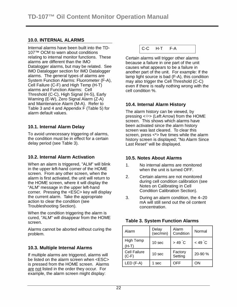
Table 3. System Function Alarms
Alarm Delay (sec/min)
Alarm Condition Normal
High Temp
(H-T) 10 sec > 49 °C < 49 °C
Cell Failure (C-F) 10 sec Factory
Setting 20-90 %
LED (F-A) 1 sec OFF ON

TD-107™ Oil Content Monitor Operation Manual
23
10.6. System Function Alarm Definitions
10.6.1. LED (F-A): Indicates the status of the excitation light source. Reports whether the LED is OFF or ON. If the power is on and the LED is functional, the diagnostic screen will display “LED: ON”.
NOTE: An extremely dirty cell condition can cause an apparent LED failure alarm.
10.6.2. Cell Failure (C-F): Indicates the flow-cell is excessively dirty, a process condition exists that will no longer allow accurate measurements to be taken, or an electronics failure has occurred.
10.6.3. High Temperature (H-T): If the bilge water exceeds 60 °C (140 °F) for 10 seconds time an H-T alarm will be displayed. Check the temperature reduction system (if installed) to determine cause of high temperature.
If a system function alarm is activated, the screen will display F-A (LED), C-F (cell failure) or H-T (high temperature) when <ESC> is pressed from the HOME screen.
F-A C-F H-T
Press <*> from the HOME screen to access the diagnostic screens (refer to Appendix F, Table 5, for default values).
If the LED displays "OFF" but there is still power to the unit and the flow-cell has been cleaned, contact your NAG Marine representative or NAG Marine at +1 757 852 3998.
Pressing <ESC> from the HOME screen allows the user to determine which function alarm is activated.
10.7. Function Alarm Definitions
Table 4. Function Alarms
Alarm Delay (sec/min)
Range Default
High Signal (H-S) 0 sec Factory
Set 15.0 ppm
Early Warning (E-W) 0 sec 0-14.9
ppm 10.0 ppm
Zero Signal (Z-A) 0 sec N/A 0.0
ppm
Maintenance (M-A) 0 sec N/A N/A
Cell Threshold (C-C)
30 sec – 30 min
OFF ON
10.7.1. High Signal Alarm (H-S)
If the measured oil in water concentration exceeds 15.0 ppm an H-S alarm will be displayed. A High Signal Alarm will be logged in the IMO Datalogger.
10.7.2. Early Warning Alarm (E-W)
If the measured oil in water concentration exceeds the Early Warning Alarm set point (default is 10.0 ppm) an E-W alarm will be displayed. An Early Warning Alarm will be logged in the IMO Datalogger.
10.7.3. Zero Signal Alarm (Z-A)
If the measured oil in water concentration equals 0.0 ppm a Z-A alarm will be displayed. A Zero Signal Alarm will be logged in the IMO Datalogger.
10.7.4. Maintenance Alarm (M-A)
If the inlet valve handle is moved to the maintenance position (handle horizontal) a M-A alarm will be displayed. A Maintenance Alarm will be logged into the
TD-107™ Oil Content Monitor Operation Manual
24
IMO Datalogger indicating maintenance is being performed.
10.7.5. Cell Threshold Alarm (C-C)
If the cell transmission % falls below the cell threshold alarm level (see Appendix B), and remains there for the Cell Delay period, a C-C alarm will be displayed. Cell transmission % values below 30 % will also generate a System Function (F-A) alarm.
If there is a C-C alarm perform the following steps:
1. Check the cell threshold alarm level to determine if it is set too high.
2. Verify that cell calibration has been performed properly.
3. Verify that the flow-cell is clean.

TD-107™ Oil Content Monitor Operation Manual
25
11.0. TROUBLESHOOTING
Because the TD-107™ OCM includes hardware, software, and chemical elements, it is important to collect all diagnostic data first. A troubleshooting worksheet is provided in Appendix G to facilitate data collection. After collecting all data on the worksheet, most problems can be solved over the phone. Refer to the Service Assistance Section for the appropriate telephone numbers.
This guide assumes that all problems associated with internal alarms have been resolved first. Something as simple as a clogged inlet line can lead to other alarm messages, which could all be solved at one time simply by clearing the obstruction. If there is no System Function Alarm (F-A), it is highly probable that the electronics of the instrument are functioning properly. In that case, it is likely that the problem is either mechanical, or has resulted from another system problem, or from the operator's unfamiliarity with the unit.
The troubleshooting procedure works best in this sequence:
1. HANDLE ANY INTERNAL ALARMS FIRST (see Internal Alarms Section)
2. Determine whether or not System Values have been entered correctly (see recorded values in Appendix B, and the System Default Values in Appendix F, Table 5).
3. Perform the Diagnostics procedure as described in the following section.
4. Determine whether or not the bilge water process is behaving as expected. Does the clean water read close to zero on the HOME screen and 15 ppm check solution read between 0–208 on the FS% diagnostic screen? Check the "CAL DATA" screen (see Calibration Data Screen) to determine whether the last calibration seems correct.
5. Complete the Troubleshooting Worksheet (Appendix G).
6. Contact your NAG Marine representative or NAG Marine at +1
757 852 3998 (see Service Assistance/Returned Goods Section).
11.1. Diagnostics
The TD-107™ OCM contains diagnostic screens and functions to aid in troubleshooting. These functions are accessed from the HOME screen by pressing <DIAG>, then <ENT> to page through the series of 7 screens. Press the <LEFT ARROW> to return to a previous screen, or <ESC> or <HOME> to return to the HOME screen.
1. From the HOME screen, press <DIAG>:
TD107
SW: V2 0730
2. From the above screen, press <ENT>:
Raw: X.XX FS% X.XXX
Raw: The "raw" signal output from the unit's light detector. This is the output the TD-107™ OCM uses (in conjunction with the Cal Solution Value and Offset) to arrive at the readout on the HOME screen. It can be used to diagnose problems with the unit. For example, if the HOME screen always reads zero, and the raw reading is also zero, there may be an optics problem. If the HOME screen reads zero but the Raw reading does not read zero, then check the Cal Solution Value to make sure the proper value is entered.
FS%: Acts like an analog meter. Indicates the raw signal output as a percentage of the maximum that can be read.

TD-107™ Oil Content Monitor Operation Manual
26
Value Range
Raw 0.00 to 1000.00 (reading >1000.00 will display "OVER")
FS% 0 to 208 (if Blank equals 0)
3. From the above screen, press <ENT>
LED: ON
LED: Indicates whether the LED light source is operational. ON is operational. OFF indicates a failure of the LED light source.
4. From the above screen, press <ENT>
FL: 0.418V
FL: Indicates the current “raw” fluorescent value as measured in the flow-cell in volts.
5. From the above screen, press <ENT>
Ref: X.XXXV Ref Cal:: X.XXXV
Ref: This value is the current reference measurement.
Ref Cal: This value is the measurement taken during the last cell calibration procedure.
6. From the above screen, press <ENT>
Cal Temp: XX.XC Max Temp: XX.XC
Cal Temp: This is the temperature of the calibration solution during the calibration procedure measured in degrees Celsius.
Max Temp: This is the maximum process water temperature the instrument has measured since the original installation.
7. From the above screen, press <ENT>
High Std: XXX.X Low Std: X.XXX
High Std: This is the stored “High Std” fluorescence value taken during the calibration procedure.
Low Std: This is the stored “Low Std” fluorescence value taken during the calibration procedure.
For definitions, ranges, and default values of these items, see Calibration Data Screen Section.
11.2. IMO Datalogger Failure
The IMO Datalogger is set-up and configured by the factory. Moving the inlet Valve 1 to the maintenance position will cause Relays 1-5 to go into alarm state and can be used for alarm circuit testing. Failure of the IMO Datalogger to retain data may be due to the back-up battery being exhausted. This battery is replaced by a factory-authorized representative during re-calibration and cannot be replaced by the end-user. There are no user-changeable features other than described here. Changing features other than described here will violate the IMO certification. There are no user serviceable components within the IMO Datalogger other than described here.
11.3. Service Assistance
The experienced technical staff of NAG Marine is available to assist you in troubleshooting the TD-107™ OCM instrument.
NAG MARINE
Telephone USA: +1 757 852 3998
E-mail: [email protected].
Hours: 8:00 am - 5:00 pm Eastern Standard Time
TD-107™ Oil Content Monitor Operation Manual
27
IMPROPER INSTALLATION, USE, APPLICATION OR UNAUTHORIZED SERVICING OF THIS EQUIPMENT VOIDS ALL GUARANTEES.

TD-107™ Oil Content Monitor Operation Manual
28
11.4. Troubleshooting Guide
[HANDLE ANY ALARMS FIRST]
SYMPTOM POSSIBLE CAUSE SOLUTION
1. System Values are incorrect (i.e .Fluor Temp Compensation, Cal Sol’n Value, etc.).
Check the Configuration Record for the site. Access the System Values and verify that they are entered correctly.
2. Incorrect calibration Check the Calibration Data screen. Contact a factory-authorized dealer for re-calibration.
HOME screen displays over/OVER (blinking from over to OVER).
A blinking 'over/OVER' is a different symptom than a steady 'OVER' and indicates that the sample reading exceeds 999. This is most likely related to the System Values entered for the site. If, for example, a Cal Sol’n Value of 200 was erroneously entered, the unit's numerical calculation of the sample reading might exceed 999. (NOTE: Examine "Possible Cause"/"Solution" in the numbered order.)
3. Controller is, or has been, in alarm
Check active alarms and correct as required.
1. Possible optics problem.
Check the FS% reading in the Diagnostics sequence.
2. Incorrect calibration. Check the Calibration Data screen. Contact a factory-authorized dealer for re-calibration.
HOME screen displays OVER (not blinking from over to OVER).
A steady 'OVER' is a different symptom than a blinking 'over/OVER' and indicates that the sample reading is too high for the unit's light detector. This is related to the chemistry of the sample and displays that the sample readings are too high for the unit at the current sensitivity level. (NOTE: Examine the "Possible Cause"/"Solution" in the numbered order.)
3. System Values are incorrect (i.e. Cal Sol’n Value, Fluor Temp Compensation etc.).
Check the Configuration Record. Access the System Values and verify they are entered correctly.
HOME screen displays minus sign (negative readings), i.e., sample is reading less concentrated than blank as set during last calibration.
1. Fouled flow-cell. Thoroughly clean and rinse flow-cell with recommended solution, using a flow-cell cleaning brush if necessary.
2. Incorrect calibration. Note: some negative measurements may occur in normal operation and can be expected.
Contact a factory-authorized dealer for re-calibration.

TD-107™ Oil Content Monitor Operation Manual
29
Troubleshooting Guide Continued
SYMPTOM POSSIBLE CAUSE SOLUTION
HOME screen reads zero. System Values incorrectly set, no water or clean water running through the monitor.
Make sure valid System Values were entered (see Appendix F).
Screen blank or black. LCD screen contrast too high or too low
If screen is blank, adjust contrast by pressing UP ARROW (if screen is black, use the DOWN ARROW) continuously until screen is visible. Use �� arrows to fine adjust.
Offset value ineffective (i.e. HOME screen reading does not change when the Offset value is changed).
This is not usually cause for alarm as the HOME screen reading is a result of a combination of factors.
Contact a factory-authorized dealer for re-calibration.
Unit does not respond to Calibration Check Solution.
System Values incorrectly entered
Ensure correct Cal Soln and Offset have been entered (see Appendix F).
Cell calibration alarm Dirty flow-cell Clean flow-cell. Re-calibrate cell condition after cleaning.
Zero Alarm (IMO Datalogger)
Clean water in flow-cell This is a normal situation. Note that a zero alarm with treated bilge water may be possible.
Data key was pulled from USB port prior to completion of downloading data.
Keep data key in USB port until LED indicates that data download has been completed.
No IMO Datalogger data on USB key
Defective data key Try another data key.

TD-107™ Oil Content Monitor Operation Manual
30
12.0. RESPONSIBILITY FOR SAFE DELIVERY
NAG Marine has done everything possible to protect this equipment from damage due to normal transportation hazards. After the product leaves the manufacturing site, responsibility for its safe handling, and delivery is assumed by the transportation company handling the equipment.
If the crated unit shows evidence of rough handling, request that the person making the delivery write "Received In Damaged Condition" on the delivery receipt. If concealed damage is revealed after the shipment is unpacked, contact a representative of the transportation company and request that a "Damaged Goods" report be completed.
In either event, the transportation company should be notified immediately of any damage to the shipment to protect your rights of recovery.
TD-107™ Oil Content Monitor Operation Manual
31
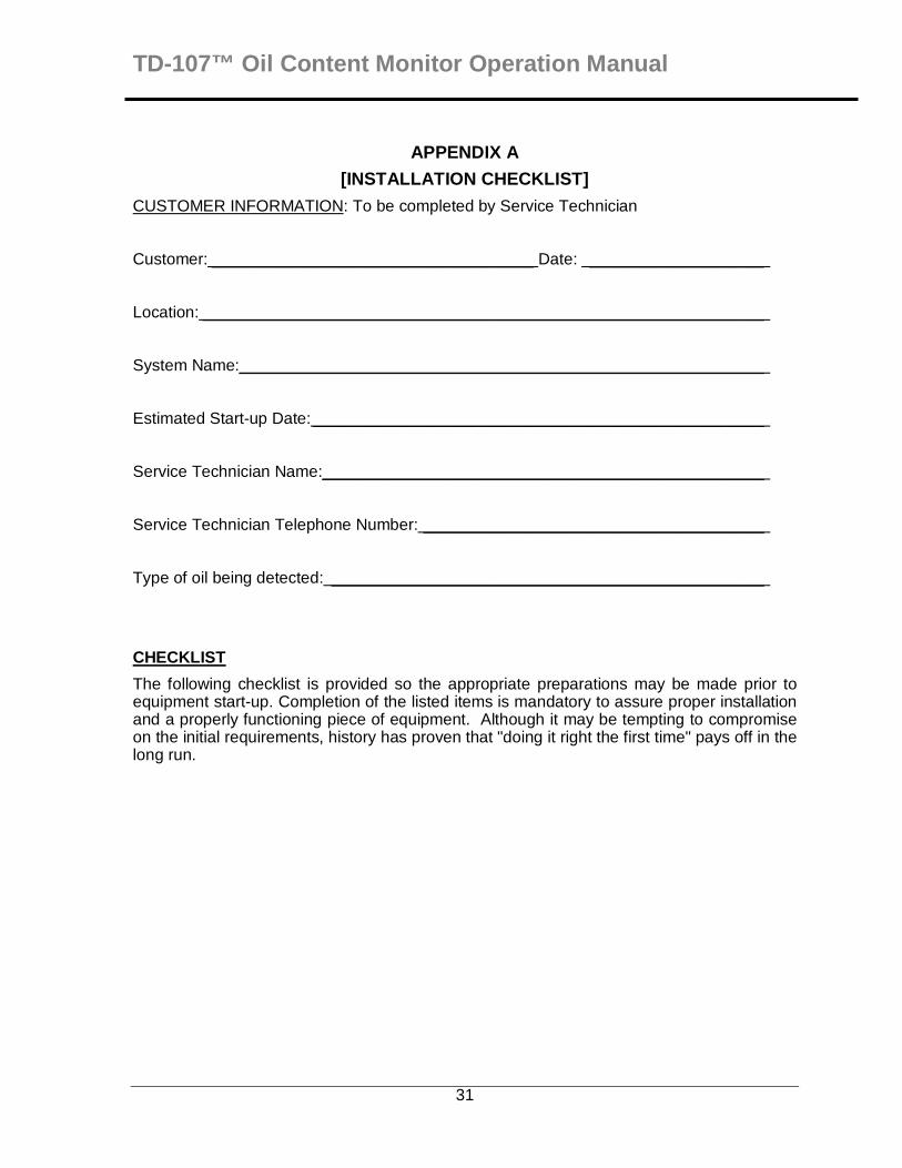
APPENDIX A
[INSTALLATION CHECKLIST]
CUSTOMER INFORMATION: To be completed by Service Technician
Customer: ___________________________________ Date: ___________________
Location: _____________________________________________________________
System Name:_________________________________________________________
Estimated Start-up Date:_________________________________________________
Service Technician Name:________________________________________________
Service Technician Telephone Number: _____________________________________
Type of oil being detected: _______________________________________________
CHECKLIST
The following checklist is provided so the appropriate preparations may be made prior to equipment start-up. Completion of the listed items is mandatory to assure proper installation and a properly functioning piece of equipment. Although it may be tempting to compromise on the initial requirements, history has proven that "doing it right the first time" pays off in the long run.

TD-107™ Oil Content Monitor Operation Manual
32
INSTALLATION CHECKLIST
To Do Complete Requirements
INITIAL REQUIREMENTS -- WATER ENGINEER
1. Ensure turbidity is less than 50 NTU. (NOTE: Install appropriate filter/strainer on inlet if
required).
2. Assure bilge water temperatures of 32–140 °F [0–60 °C].
INSTALLATION REQUIREMENTS -- WATER ENGINEER
1. Locate unit within 25 ft [7.62 m] from sample point.
2. Locate unit out of direct sunlight.
3. Locate unit where ambient temperatures are 40–120 °F [4–49 °C].
4. Locate unit at least 10 ft [3.048 m] from devices such as large generators, which require
a great deal of electrical power, or generate a strong electromagnetic field.
CUSTOMER REQUIREMENTS – PLUMBER
1.
Sample stream must be plumbed to the unit to deliver at a rate greater than 0.13 U.S. gal/min [0.5 L/min], less than 1.0 U.S. gal/min [3.78 L/min] and less than 100 psig [689.5 kPa(g)]. One 0.25 in. FNPT pipe connections is provided for pipe inlet hook-up. One ¼ inch Swagelok is provided discharge water (see Figure 1). NAG Marine recommends flex lines for the inlet/outlet connections. Ensure sampling point avoids air entrapment.
2. Sample from side of water line to avoid air entrapment (if appropriate).
3. Provide free, unrestricted drain for sample stream if possible.
CUSTOMER REQUIREMENTS – ELECTRICIAN
1. Ensure environment will support a NEMA 4-type enclosure.
2.
Provide continuous 20–240 VAC/VDC, 50/60 Hz, 15 watt electrical service to the TD-107™ OCM.
Connect the High Signal (15 ppm) Alarm Relay to the bilge water treatment system diverter valve.
3.
Connect the separator system status input and flow status input to the TD-107™ OCM.
FINAL REQUIREMENTS -- WATER ENGINEER AND CUSTOMER
1. If the unit is to be installed by a third party arrange a time during start-up when you and the customer can be trained together.
Obtain needed materials (15 ppm check solution, 0ppm clean water, cleaning solutions, accessory kit, and flow-cell cleaning brushes) prior to commissioning the System.
Customer Responsibilities: This checklist outlines work required prior to start-up. This work is necessary to ensure quality and proper operation. However, if any of these requirements cannot be met, contact your NAG Marine representative or NAG Marine.

TD-107™ Oil Content Monitor Operation Manual
33
APPENDIX B
[CONFIGURATION RECORD]
Date Configured:__________________________________________________________
Factory Authorized Company:_________________________________________________
Service Engineer Name: ____________________________________________________
System Name:____________________________________________________________
System S/N: ____________________
System
Value
Access
Keys Range Value
High Std. Conc. <HOME> <0><1> 15.0 ppm
Low Std. Conc. <HOME> <0><2> 0.0 ppm
High Signal Alarm <HOME> <1> 15.0 ppm
Early Warning Alarm <HOME> <2> 10.0-14.9 ppm
Zero Signal Alarm <HOME> <3> 0.0 to 2.0 ppm
4mA Output <HOME> <4> 0.0 ppm
20mA Output <HOME> <6> 30.0 – 100.0 ppm
Cell Threshold Value <HOME> <7> 10-90%
Cell Delay <HOME> <8> 30 sec to 30 min

TD-107™ Oil Content Monitor Operation Manual
34
APPENDIX C
[TD-107™ OCM CONTROL FUNCTIONS]
TD-107™ OCM provides the following control function s:
1. Activates the High Signal Alarm upon the concentration reaching 15.0 ppm.
2. Activates the Early Warning Alarm upon the concentration reaching 10.0 ppm.
3. Activates the Zero Signal Alarm when the concentration is measured at approximately 0.0ppm.
4. Activates a System Alarm when there is a monitor failure.
5. Activates High Signal Alarm, Early Warning Alarm, Zero Signal Alarm, and System Alarm Relays when Valve 1 is put into the maintenance position.
6. Activates the Cell Condition Alarm when the cell condition is below the Cell Threshold limit. In addition to the Cell Condition Alarm, a System alarm will also be activated if the Cell Condition falls below a minimum setting that cannot be adjusted.
The unit is a microprocessor-based instrument designed to measure the oil content in the sample, display the current oil content, and report the value to the IMO Datalogger. The digital display shows the oil content (0.000–999 ppm), any internal alarm notification, process water temp and the cell condition %. Additional information is displayed or changed by pressing various keys on the keypad on the unit. Additional information is also recorded in the IMO Datalogger. See Figures (1) through (6) for the location of the following controls on the unit:
LCD Digital Display
Continuously displays HOME screen when values are not being entered or viewed. Except during cell condition calibration, the contrast of the LCD can be adjusted on any screen by pressing the UP or DOWN ARROW.
Keypad Used to enter new unit values and to move between screens.
Main Power Switch
Main power switch for entire unit -- When ON, the LCD will illuminate.
Inlet Valve 1 Directs sample flow to unit or allows injection of solutions into the monitor. When Valve 1 is moved to the maintenance position, sample flow is stopped, permitting solutions to be injected into unit via the Luer Lock injection port. This valve also contains the maintenance mode switch, which is active when flow is stopped to the monitor.
Outlet Valve 2
(Optional)
Directs sample flow from the outlet of the flow-cell. When the green handle is vertical, the valve is open and sample flows into the process. When green handle is horizontal, sample flow into the process is stopped, permitting atmospheric drain conditions required of calibration or cleaning of the flow-cell. Warning ! Cleaning solutions should not be reintroduced to process streams.
Luer-Lok™ Injection Port
During instrument calibration checking, solutions are injected into the unit using a syringe at the Luer-Lok™ connection point.
Clean-out Plug Permits access to flow-cell for cleaning with a brush when flushing with acid alone is not effective. Several spare plugs are provided.
Sample In Where sample intake line is attached to allow sample to flow through unit.
Sample Out Sample outlet line attaches here.
Sample Block Houses flow-cell and optical filters. The sample block must be replaced by a factory authorized dealer.

TD-107™ Oil Content Monitor Operation Manual
35
Input/Output Cabling
Pre terminated cabling is provide with the TD-107™ OCM for the power, IMO Datalogger Relays, Bilge Separator Status input, Sample Flow Status input, and 4–20 mA analog out connections are made on this strip (see Figure (7)). Only trained personnel should make electrical connections.
USB Data Key Port
Located on the bottom face of the electrical enclosure. Provides access for retrieving IMO Datalogger data.
Data Status Indicator
An LED which indicates the status of the data downloading and data recording.

TD-107™ Oil Content Monitor Operation Manual
36
APPENDIX D
[TD-107™ OCM SOFTWARE FUNCTIONS]
The unit has a software interface that simplifies evaluation (see Screens Flow Charts in Appendix E). The following descriptions of the unit's software functions will help provide a better understanding of the unit:
D.1. Screens A series of computerized screens built into the unit are called up using the keypad and shown on the digital display.
D.1.1. Home Screen
Once the unit has been activated, the HOME screen is continuously displayed, except when accessing other screens.
From the HOME screen, access the calibration data by pressing <ENT>. Other screens are accessed from the HOME screen by pressing various keys on the keypad (Appendix E).
Go to the HOME screen by pressing the <HOME> key, except during the calibration procedure.
D.1.2. Warning Screens
There are warning screens throughout the software, which inform of invalid entries (for values or ID).
D.1.3. Internal Alarms
When an internal alarm occurs, "ALM" blinks in the upper left-hand corner of the HOME screen. The nature of the alarm can be discovered by pressing <ESC> from the HOME screen (see Alarms and Troubleshooting Sections).
D.2. Keypad Functions D.2.1. Left Arrow
The left arrow can be used to correct typing errors when data is being entered or changed. It acts as a backspace or delete key. It is also used from the HOME screen to view the alarm history.
D.2.2. Up & Down Arrows
From HOME screen, these arrows can be used to change screen contrast.
D.2.3. Escape & Enter
You can escape to the previous screen or abort the calibration sequence by pressing the <ESC> key. While viewing a System Value, press <ENT> to access the screen to change that value. After entering a new System Value, press <ENT> to accept the new value.
D.3. User Identification The TD-107™ OCM is protected from unauthorized changes by passwords. These passwords are not available or provided to the end-user.
D.4. Fluorescence Display After the unit is powered-up or after cell calibration, the oil content displayed will not react immediately, but will respond after a delay of about 10 seconds.
D.5. LCD Contrast The contrast of the Liquid Crystal Display (LCD) can be adjusted on any screen (except during calibration) by pressing the up & down arrows.

TD-107™ Oil Content Monitor Operation Manual
37
APPENDIX E
[SCREEN FLOW CHARTS]
E.1. System Value Screens E.2. Diagnostic Screens
Home 0.123 PPM T: 23C Cell: 100%
Home shows fluorescent response, water temperature, cell transmission %
DIAG
TD-107 SW: V2. 0730
0 <1> Hi Std Conc <2> Low Std Conc
Relates calibration standard to a fluorescence measurement
ENT
Raw: XXX FS%: XXXX
1 High Sig Alarm 15.000 PPM
Active if fluorescent measurement is above 15.0 ppm
ENT
LED: ON
2 Early Warning 10.000 PPM
Active if fluorescent measurement is above the Early Warning set point.
ENT
FL: XXX.X V
3 Zero Sig Alarm 0.000 PPM
Active if fluorescent measurement is above the Zero Sig set point.
ENT
REF: X.XXX V REF CAL: XXX.X V
4 4mA Output 0.000 PPM Set output to a desired
level of fluorescence ENT
CAL TEMP: XX.X C MAX TEMP: XX.X C
5 Change User ID To change user ID.
ENT
High Std: XXX.X Low Std: X.XXX
6 20mA Output 30.000 PPM
Set output to desired level of fluorescence
7 Cell Threshold Set cell transmission threshold
8 Cell Delay Set cell transmission alarm delay
. Cell Calibration Initiate Cell calibration
← Alarm History Displays past alarm history

TD-107™ Oil Content Monitor Operation Manual
38
ESC View Current Alarms Displays current active alarms
From the HOME screen, press <�> to access the Date & Time functions. The date and time functions are not end-user accessible.
E.3. Cell Calibration Screens
HOME
XXXX PPM T: 23C Cell: 100%
1. From the HOME Screen press <.>
.
CELL CALIBRATION <ENT> TO START
2. Press <NET> to initiate the cell calibration sequence
ENT
FLOW-CELL CLEAN? <ENT> TO CONT.
3. Press <ENT> if the flow-cell is clean. Press <HOME> and clean flow-cell if flow-cell if necessary. Restart cell calibration after cleaning flow-cell.
ENT
PROCESS WATER? <ENT> TO CONT.
4. Press <ENT> Open inlet process water valve to the open position (handle vertical). Verify outlet valve is open to process (handle is vertical).
ENT
CELL CAL. 0.XXX V <*> TO CONT.
5. Press <*> when ready to start.
*
CELL CALIBRATION X.XXX V wait/WAIT
6. Wait until the measurement has been completed. The screen then will advance to the next screen below.
1
PRESS <1> TO END CALIBRATION
7. Press <1> to accept the cell calibration.

TD-107™ Oil Content Monitor Operation Manual
39
APPENDIX F
[SYSTEM, CLOCK, AND ALARM VALUES]
System Values are accessed from the HOME screen (see Appendix E). Default values are listed in Table 5 below. Refer to Appendix B to determine how the unit was configured at the time of installation.
• View the System Values by pressing the appropriate access key while on the HOME screen.
• These values can only be changed by a factory-authorized service engineer and are not user-changeable.
Table 5. System Default Values and Ranges
System Value Access Key Default Value Range
High Std Conc <0><1> 15.0 15.0
Low Std Conc <0><2> 0.000 ± 10
High Signal Value <1> 15.0 15.0
Early Warning <2> 10.0 10.0-14.9
Zero Sig Alarm <3> 0.0 0.0 – 2.0
4 mA Output <4> 0.000 0.000 ppm
End User ID <5> 0258 0000 to 9999
20 mA Output <6> 30.0 30 ppm
Cell Threshold % <7> 80%
10 to 90% Note: values of 30% or lower will generate a System alarm.
Cell Delay Interval <8> 20 sec 20 sec
Software Version <DIAG> NA Fixed
F.1. System Value Definitions
<0> <1> HIGH STD CONC
Relates the fluorescence measurement value to a high standard concentration reference oil content fluorescence measurement.
<0> <2> LOW STD CONC
Relates the fluorescence measurement value to a low standard concentration reference oil content fluorescence measurement.
<1> HIGH SIGNAL VALUE
If the oil content rises above 15.0 ppm a high signal alarm will be triggered and sent to the IMO Datalogger. There is no delay.
<2> EARLY WARNING ALARM
If the oil content rises above this level, an early warning alarm will be triggered and sent to the IMO Datalogger. There is no delay.
<3> ZERO SIGNAL ALARM
If the oil content decreases to approximately 0.0 ppm, a zero signal alarm will be triggered and sent to the IMO Datalogger. There is no delay.
<4> 4 MA OUTPUT
The lower limit of the analog output sent to the IMO Datalogger, which is 0 ppm.
During an alarm condition, the 4–20 mA output will still send out the measurement

TD-107™ Oil Content Monitor Operation Manual
40
level. During cell calibration the 4–20 mA output will send out a 4 mA signal.
<5> END-USER ID
Allows the End-User ID to be changed by entering in the Master ID. Must be obtained from factory-authorized representative.
<6> 20 MA OUTPUT
The upper limit of the analog output sent to the IMO Datalogger, which is 30 ppm.
<7> Cell Threshold Value
This value defines the transmission % at which the operator should clean the flow-cell. The real time cell condition % is compared to the Cell Condition % measured during Cell Calibration.
<8> CELL DELAY
This value defines how much time the Cell Condition % must exceed the minimum Cell Threshold % before trigging the Cell Condition Alarm.
NOTE: The date and time values are accessed under the <�> menu. The IMO Datalogger date and time are set to Greenwich Mean Time (GMT) regardless of the date and time setting in the TD-107™ OCM. The time and date cannot be changed.
Pressing the <�> key will display the current date and time.
Example <�> screen:
<0> to 02/21/07 <5> xx:xx:xxam
TD-107™ Oil Content Monitor Operation Manual
41
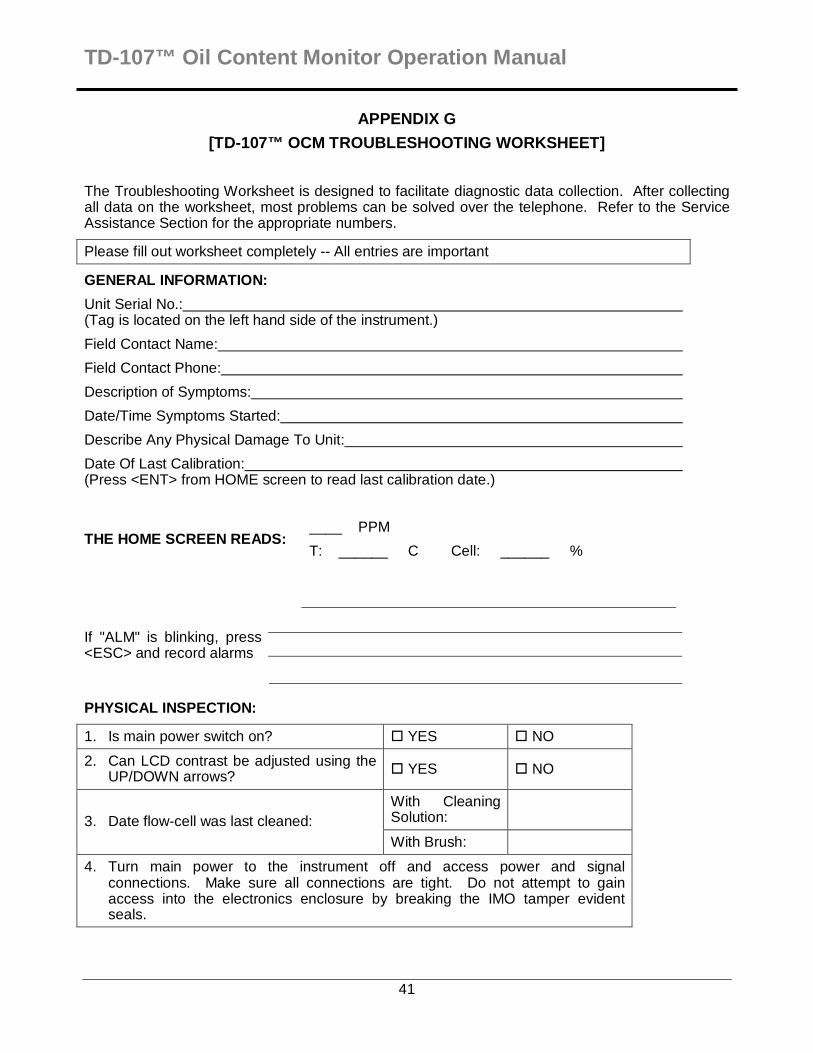
APPENDIX G
[TD-107™ OCM TROUBLESHOOTING WORKSHEET]
The Troubleshooting Worksheet is designed to facilitate diagnostic data collection. After collecting all data on the worksheet, most problems can be solved over the telephone. Refer to the Service Assistance Section for the appropriate numbers.
Please fill out worksheet completely -- All entries are important
GENERAL INFORMATION:
Unit Serial No.: (Tag is located on the left hand side of the instrument.)
Field Contact Name:
Field Contact Phone:
Description of Symptoms:
Date/Time Symptoms Started:
Describe Any Physical Damage To Unit:
Date Of Last Calibration: (Press <ENT> from HOME screen to read last calibration date.)
THE HOME SCREEN READS: ____ PPM
T: ______ C Cell: ______ %
If "ALM" is blinking, press <ESC> and record alarms
PHYSICAL INSPECTION:
1. Is main power switch on? � YES � NO
2. Can LCD contrast be adjusted using the UP/DOWN arrows? � YES � NO
With Cleaning Solution:
3. Date flow-cell was last cleaned:
With Brush:
4. Turn main power to the instrument off and access power and signal connections. Make sure all connections are tight. Do not attempt to gain access into the electronics enclosure by breaking the IMO tamper evident seals.
. 42
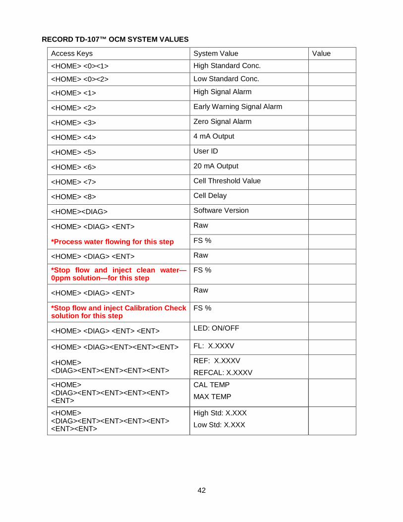
RECORD TD-107™ OCM SYSTEM VALUES
Access Keys System Value Value
<HOME> <0><1> High Standard Conc.
<HOME> <0><2> Low Standard Conc.
<HOME> <1> High Signal Alarm
<HOME> <2> Early Warning Signal Alarm
<HOME> <3> Zero Signal Alarm
<HOME> <4> 4 mA Output
<HOME> <5> User ID
<HOME> <6> 20 mA Output
<HOME> <7> Cell Threshold Value
<HOME> <8> Cell Delay
<HOME><DIAG> Software Version
<HOME> <DIAG> <ENT> Raw
*Process water flowing for this step FS %
<HOME> <DIAG> <ENT> Raw
*Stop flow and inject clean water—0ppm solution—for this step
FS %
<HOME> <DIAG> <ENT> Raw
*Stop flow and inject Calibration Check solution for this step
FS %
<HOME> <DIAG> <ENT> <ENT> LED: ON/OFF
<HOME> <DIAG><ENT><ENT><ENT> FL: X.XXXV
<HOME> <DIAG><ENT><ENT><ENT><ENT>
REF: X.XXXV
REFCAL: X.XXXV
<HOME> <DIAG><ENT><ENT><ENT><ENT> <ENT>
CAL TEMP
MAX TEMP
<HOME> <DIAG><ENT><ENT><ENT><ENT> <ENT><ENT>
High Std: X.XXX
Low Std: X.XXX