tcp behavior in quality of service networks
TRANSCRIPT

TCP Behavior in Quality of Service Networks
by
Sanjeewa Athuraliya
A thesis submitted in conformity with the requirementsfor the degree of Doctor of Philosophy
Department of Electrical and Computer EngineeringUniversity of Canterbury
Copyright c© 2007 by Sanjeewa Athuraliya

Abstract
TCP Behavior in Quality of Service Networks
Sanjeewa Athuraliya
Doctor of Philosophy
Department of Electrical and Computer Engineering
University of Canterbury
2007
Best effort networks fail to deliver the level of service emerging Internet applications
demand. As a result many networks are being transformed to Quality of Service (QoS)
networks, of which most are Differentiated Services (DiffServ) networks. While the de-
ployment of such networks has been feasible, it is extremely difficult to overhaul the
transport layer protocols such as Transmission Control Protocol (TCP) running on hun-
dreds of millions of end nodes around the world. TCP, which has been designed to run
on a best effort network, perform poorly in a DiffServ network. It fails to deliver the
performance guarantees expected of DiffServ. In this thesis we investigate two aspects of
TCP performance in a DiffServ network unaccounted for in previous studies. We develop
a deterministic model of TCP that intrinsically captures flow aggregation, a key com-
ponent of DiffServ. The other important aspect of TCP considered in this thesis is its’
transient behavior. Using our deterministic model we derive a classical control system
model of TCP applicable in a DiffServ network.
Performance issues of TCP can potentially inhibit the adoption of DiffServ. A DiffServ
network commonly use token buckets, that are placed at the edge of the network, to
mark packets according to their conformance to Service Level Agreements (SLA). We
propose two token bucket variants designed to mitigate TCP issues present in a DiffServ
network. Our first proposal incorporates a packet queue alongside the token bucket. The
other proposal introduces a feedback controller around the token bucket. We validate
ii

both analytically and experimentally the performance of the proposed token buckets.
By confining our changes to the token bucket we avoid any changes at end-nodes. The
proposed token buckets can also be incrementally deployed.
Most part of the Internet still remains as a best effort network. However, most nodes
run various QoS functions locally. We look at one such important QoS function, i.e.
the ability to survive against flows that are non-responsive to congestion, the equiva-
lent of a Denial of Service (DoS) attack. We analyze existing techniques and propose
improvements.
iii

Dedication
For my family, who offered me unconditional love and support throughout the course of
this thesis. I would like to dedicate this thesis in the loving memory of my father.
iv

Acknowledgements
Firstly, I would like to thank my advisor, Prof. Harsha Sirisena. Drawing on years of
experience and wisdom, he was the best advisor and mentor I could have ever asked
for. He held no reservations in approving my part-time candidature. It helped instill
confidence within me. Without his sound advice and careful guidance I would not have
been able to complete this.
Financial assistance provided by the Foundation for Research Science and Technology
of New Zealand (FRSTNZ) is acknowledged with great appreciation.
I have been so fortunate to have worked at Allied Telesis Labs (ATL) during most
part of my candidature. It was a memorable educational experience. Though I can’t be
certain, that experience must have helped shape this thesis in some way. I was privileged
to have great colleagues at ATL. I would like to thank them, not so much for any technical
input, but being such a wonderful bunch of people.
I am extremely fortunate to have in-laws who were willing to leave their familiar
surroundings thousands of miles away and help us look after children and take care of
household chores. Their help and support gave me the precious time and energy to
complete this thesis. I am forever indebted for their kindness.
Finally, a big thank you to my wife and two daughters. This is a PhD completed
after-hours, the time I should have spent with them. Every minute I was working on my
thesis, is a minute they missed being with me. Thank you for your endless patience and
encouragement.
v

Contents
1 Introduction 1
1.1 Motivation . . . . . . . . . . . . . . . . . . . . . . . . . . . . . . . . . . . 1
1.2 Thesis Outline . . . . . . . . . . . . . . . . . . . . . . . . . . . . . . . . . 4
1.3 Publication List . . . . . . . . . . . . . . . . . . . . . . . . . . . . . . . . 5
2 Background 6
2.1 Internet - Historical Perspective . . . . . . . . . . . . . . . . . . . . . . . 6
2.2 Quality of Service Architectures . . . . . . . . . . . . . . . . . . . . . . . 7
2.2.1 Intserv . . . . . . . . . . . . . . . . . . . . . . . . . . . . . . . . . 7
2.2.2 DiffServ . . . . . . . . . . . . . . . . . . . . . . . . . . . . . . . . 9
2.3 Transmission Control Protocol . . . . . . . . . . . . . . . . . . . . . . . . 13
3 Modeling TCP Behavior in a DiffServ Network 16
3.1 Related Work: TCP Behavior in a Best Effort Network . . . . . . . . . . 17
3.2 Related Work: TCP Behavior in a DiffServ Network . . . . . . . . . . . . 19
3.3 Our Contributions . . . . . . . . . . . . . . . . . . . . . . . . . . . . . . 22
3.4 The Network Model . . . . . . . . . . . . . . . . . . . . . . . . . . . . . . 23
3.5 Aggregate TCP Congestion Window Behavior . . . . . . . . . . . . . . . 26
3.5.1 Behavior 1 . . . . . . . . . . . . . . . . . . . . . . . . . . . . . . . 26
3.5.2 Behavior 2 . . . . . . . . . . . . . . . . . . . . . . . . . . . . . . . 28
3.5.3 Behavior 3 . . . . . . . . . . . . . . . . . . . . . . . . . . . . . . . 29
vi

3.5.4 Behavior 4 . . . . . . . . . . . . . . . . . . . . . . . . . . . . . . . 32
3.5.5 Behavior 5 . . . . . . . . . . . . . . . . . . . . . . . . . . . . . . . 32
3.6 Steady State Behavior . . . . . . . . . . . . . . . . . . . . . . . . . . . . 33
3.6.1 Multiple Packet Drops . . . . . . . . . . . . . . . . . . . . . . . . 36
3.7 Transient Behavior . . . . . . . . . . . . . . . . . . . . . . . . . . . . . . 38
3.8 Simulation Studies . . . . . . . . . . . . . . . . . . . . . . . . . . . . . . 40
3.8.1 Experiment 1 . . . . . . . . . . . . . . . . . . . . . . . . . . . . . 41
3.8.2 Experiment 2 . . . . . . . . . . . . . . . . . . . . . . . . . . . . . 42
3.8.3 Experiment 3 . . . . . . . . . . . . . . . . . . . . . . . . . . . . . 42
4 Improving TCP Behavior in a DiffServ Network 45
4.1 Related Work . . . . . . . . . . . . . . . . . . . . . . . . . . . . . . . . . 45
4.2 Our Contributions . . . . . . . . . . . . . . . . . . . . . . . . . . . . . . 48
4.3 Token Bucket and a Queue . . . . . . . . . . . . . . . . . . . . . . . . . . 48
4.3.1 Network Model and Analysis . . . . . . . . . . . . . . . . . . . . . 50
4.3.2 Low Delay Packet Marker . . . . . . . . . . . . . . . . . . . . . . 54
4.3.3 Simulation Studies - TBQ . . . . . . . . . . . . . . . . . . . . . . 55
4.4 Continuous Active Rate Management . . . . . . . . . . . . . . . . . . . . 63
4.4.1 Network Model . . . . . . . . . . . . . . . . . . . . . . . . . . . . 65
4.4.2 Controller Design . . . . . . . . . . . . . . . . . . . . . . . . . . . 67
4.4.3 Simulation Studies - CARM . . . . . . . . . . . . . . . . . . . . . 70
5 Promoting Conformance to TCP 81
5.1 Our Contributions . . . . . . . . . . . . . . . . . . . . . . . . . . . . . . 82
5.2 Related Work . . . . . . . . . . . . . . . . . . . . . . . . . . . . . . . . . 82
5.3 Protective Queue Management . . . . . . . . . . . . . . . . . . . . . . . . 86
5.4 Simulation Studies . . . . . . . . . . . . . . . . . . . . . . . . . . . . . . 91
5.4.1 Experiment 1 . . . . . . . . . . . . . . . . . . . . . . . . . . . . . 91
vii

5.4.2 Experiment 2 . . . . . . . . . . . . . . . . . . . . . . . . . . . . . 93
5.4.3 Experiment 3 . . . . . . . . . . . . . . . . . . . . . . . . . . . . . 94
6 Conclusion 95
Bibliography 98
viii

List of Figures
2.1 Color-Aware mode of SRTCM . . . . . . . . . . . . . . . . . . . . . . . . 12
3.1 A Simplified DiffServ Network Model . . . . . . . . . . . . . . . . . . . . 19
3.2 Non-Overlapping Drop Precedence Curves in a DiffServ Network . . . . . 22
3.3 The Aggregate TCP Congestion Window. . . . . . . . . . . . . . . . . . 24
3.4 The Aggregate TCP Congestion Window for A = 40000, pr = 0.2, n = 20,
B = 50, T = 0.1 . . . . . . . . . . . . . . . . . . . . . . . . . . . . . . . . 27
3.5 The Aggregate TCP Congestion Window for A = 24000, pr = 0.2, n = 20,
B = 50, T = 0.1 . . . . . . . . . . . . . . . . . . . . . . . . . . . . . . . . 29
3.6 The Aggregate TCP Congestion Window for A = 16000, pr = 0.2, n = 20,
B = 50, T = 0.1 . . . . . . . . . . . . . . . . . . . . . . . . . . . . . . . . 31
3.7 The Aggregate TCP Congestion Window for A = 6000, pr = 0.2, n = 20,
B = 50, T = 0.1 . . . . . . . . . . . . . . . . . . . . . . . . . . . . . . . . 31
3.8 The Aggregate TCP Congestion Window for A = 4000, pr = 0.2, n = 20,
B = 50, T = 0.1 . . . . . . . . . . . . . . . . . . . . . . . . . . . . . . . . 33
3.9 The Aggregate TCP Congestion Window for A = 500, pr = 0.2, n = 20,
B = 50, T = 0.1 . . . . . . . . . . . . . . . . . . . . . . . . . . . . . . . . 34
3.10 The Effect of Network Parameters on TCP Excess Bandwidth . . . . . . 37
3.11 Modeling TCP Behavior: Simulation Network Topology . . . . . . . . . . 40
3.12 Model predicted aggregate TCP Rate for Different Contract Rates . . . . 41
3.13 Aggregate TCP Rate for Different Numbers of Flows per Aggregate . . . 42
ix

3.14 Aggregate TCP Rate for Different Network Parameters . . . . . . . . . . 44
4.1 The Aggregate TCP Congestion Window . . . . . . . . . . . . . . . . . . 52
4.2 TBQ Performance: Simulation Network Topology . . . . . . . . . . . . . 57
4.3 TBQ Performance for Different Values of A. . . . . . . . . . . . . . . . . 58
4.4 TBQ Performance in an Exact-Provisioned Network . . . . . . . . . . . . 59
4.5 TBQ Performance in a 20% Over-Provisioned Network . . . . . . . . . . 60
4.6 TBQ Performance in a 20% Under-Provisioned Network . . . . . . . . . 61
4.7 TBQ Performance in an Exact-Provisioned Network with Background Traffic 62
4.8 TBQ Performance in a 20% Over-Provisioned Network with Background
Traffic . . . . . . . . . . . . . . . . . . . . . . . . . . . . . . . . . . . . . 63
4.9 The Aggregate TCP Congestion Window. . . . . . . . . . . . . . . . . . 66
4.10 CARM: Feed Back Control System. . . . . . . . . . . . . . . . . . . . . . 68
4.11 CARM Performance: Simulation Network Topology . . . . . . . . . . . . 69
4.12 CARM Performance for Different Values of A. . . . . . . . . . . . . . . . 71
4.13 CARM Performance for Different Values of Kc. . . . . . . . . . . . . . . 72
4.14 CARM Performance in an Exact-Provisioned Network. . . . . . . . . . . 74
4.15 CARM Performance in a 20% Over-Provisioned Network. . . . . . . . . . 75
4.16 CARM Performance in a 20% Under-Provisioned Network. . . . . . . . . 76
4.17 CARM Performance in an Exact-Provisioned Network with Background
Traffic. . . . . . . . . . . . . . . . . . . . . . . . . . . . . . . . . . . . . . 77
4.18 CARM Performance in an Over-Provisioned Network with Background
Traffic. . . . . . . . . . . . . . . . . . . . . . . . . . . . . . . . . . . . . . 78
4.19 CARM Performance under a Varying Network Load. . . . . . . . . . . . 80
5.1 PQM Performance: Extreme Traffic Load . . . . . . . . . . . . . . . . . . 92
5.2 PQM Performance: Moderate Traffic Load . . . . . . . . . . . . . . . . . 93
5.3 PQM Performance: Different Packet Sizes . . . . . . . . . . . . . . . . . 94
x

Chapter 1
Introduction
1.1 Motivation
The migration of a raft of diverse applications in recent years has transformed the Inter-
net to a convergent network carrying triple play services of voice, video and data. In large
measure, this has been realised due to the deployment of Quality of Service (QoS) archi-
tectures such as Integrated Services (IntServ) [21], Differentiated Services (DiffServ) [19]
and more recently Multi Protocol Label Switching (MPLS) [84]. Users, who increasingly
rely on the Internet for communication needs, seek guaranteed service levels. Service
providers, on the other hand, increase profitability with an assortment of higher margin
differentiated services. As a result, the last few years have seen a widespread deployment
of QoS networks. Given the decentralised nature of the Internet protocols and the lack
of signaling within the network, no single node can exert absolute control over the entire
communication path. For example, nodes in the network core, routers and switches,
have only loose control over the rate of packet transmission of end devices. Therefore,
guaranteeing specific levels of service for Internet applications has become a challenging
task.
The Internet carries traffic belonging to many different applications that have diverse
1

Chapter 1. Introduction 2
requirements. There has been a proliferation of fixed bandwidth and delay sensitive real-
time applications that deploy aggressive transport layer protocols; e.g. Voice over IP
(VoIP), Video on Demand (VoD), Internet Protocol Television (IPTV). They clutter the
bandwidth space and can potentially deprive mission-critical business applications of the
necessary bandwidth to maintain application performance. Increasingly these applica-
tions rely on services that provide minimum guaranteed bandwidths. However, providing
per-flow service guarantees is not scalable in a large network like the Internet. Aggre-
gation of flows at the network edge and processing the aggregates in the network core
as done in DiffServ has, however, gained popularity. DiffServ has defined the Assured
Forwarding (AF) Per-Hop-Behavior (PHB) [43] for applications that require guaranteed
minimum bandwidths. Though a certain bandwidth is guaranteed, in most cases ap-
plications are allowed access to the full network bandwidth to make efficient use of the
available network bandwidth. In either case, limiting the bandwidth at the guaranteed
minimum bandwidth level or allowing expansion up to the available network capacity,
routers use network congestion events such as dropping packets or marking the Explicit
Congestion Notification (ECN) [81], [39] bit to regulate the rate of packets transmission
at the edge of the network. Congestion reactive protocols at the transport layer such
as Transmission Control Protocol (TCP) help end nodes regulate the rate because of
these congestion events in the network core. Due to the lack of precise feedback avail-
able on the level of congestion, as in the Internet, end nodes take drastic preventive
action in response to congestion events. TCP infers incipient congestion through ECN,
duplicate acknowledgments or timeouts and in turn varies the congestion window, which
is the allowed number of unacknowledged packets in transit across the network. Most
implementations of TCP increase the congestion window by one per round trip time in
the absence of any congestion notifications but otherwise attempt to ease congestion by
halving the congestion window. To achieve guaranteed minimum bandwidths, DiffServ
capable routers at the edge of the network embed code points in the packets to indicate

Chapter 1. Introduction 3
compliance to SLAs. Routers in the network core handle packets according to this code
point. Packets that are in-profile are less likely to be dropped or marked compared to
out-of-profile packets. Despite the use of a marking scheme, due to the complex way TCP
reacts to congestion, TCP flow aggregates often fall short of guaranteed bandwidths in
realistic network scenarios.
This weakness of TCP has been an impediment for the successful deployment of
DiffServ. This has motivated several studies that have explored ways to overcome this
limitation. However, proposed algorithms, as our analysis shows, either distort Diff-
Serv functionality or impose major changes across the Internet including end nodes.
This dissertation presents two new packet markers that eliminate these limitations while
effectively enabling TCP flow aggregates to reach contract rates. Their performance is
validated both theoretically and experimentally. The DiffServ induced code point change
in the IP header effectively alters TCP dynamics. Many studies have characterized, to
varying degrees, the steady state throughput of a Diffserv controlled TCP aggregate.
Studying the transient behavior, which hasn’t so far been dealt with in any previous
work, is equally important. For example, the ability to represent dynamics in a con-
trol system model allows analysis-based guidelines for choosing optimal parameters of
DiffServ elements, such as packet markers. We develop from first principles a model
of a DiffServ controlled TCP flow aggregate in an over-provisioned network, providing
insights to both the transient and steady state behavior. We represent this in a control
system model and as a practical application use it to derive optimal parameter values of
one of the proposed markers.
Though QoS networks such as DiffServ networks are fast gaining popularity, most
of the Internet still provides a best effort service. It is vital that nodes of a best effort
network run QoS functions. One such important QoS function is survival in the pres-
ence of congestion non-responsive flows. Buffer acceptance techniques are designed to
perform that functionality. This dissertation proposes a new buffer acceptance algorithm

Chapter 1. Introduction 4
that also behaves as a penalty box, which promotes conformance to a bandwidth used by
a TCP flow. Buffer acceptance algorithms look more attractive as they bear less over-
head compared to packet scheduling algorithms. Previously proposed algorithms rely on
various statistical measurements such as buffer occupancy and packet drop history to
identify misbehaving flows. We investigate their effectiveness. Our analysis shows that
buffer occupancy or packet drop history can distort the bandwidth share estimation of a
flow. This motivates our alternative approach.
The summary of the main contributions of this thesis can be stated as:
• Develop a model of TCP that intrinsically captures DiffServ flow aggregation. This
allows us to accurately measure the effect that the number of flows per aggregate
imparts on TCP throughput.
• Analyze convergence properties of the aggregate TCP congestion window size in
wide-ranging conditions. This provides insights to TCP congestion window’s oscil-
latory behavior.
• Study both the transient and steady state TCP behavior. We represent DiffServ
controlled TCP dynamics in a classical control system model. It allows use of
standard techniques to analyze various mechanisms and propose improvements to
algorithms as well as analysis-backed guidelines for choosing parameters of the
algorithms.
• Derive more complete expressions for excess bandwidth distribution in terms of
number of flows per aggregate, RTT, contract rate, and token bucket size.
• Investigate the benefits of using a packet queue at the token bucket to improve
TCP performance in a DiffServ network. We show that the required size of the
token bucket grows exponentially with the contract rate, whereas a packet queue
needs to be only linearly proportional to the contract rate to prevent TCP flow
aggregates falling short of contract rates.

Chapter 1. Introduction 5
• Propose improvements to a proposed feedback controller around the token bucket.
We show that its performance can be drastically improved by comparing the rate
of only in-profile packet transmissions to the contract rate as opposed to using
the total rate of packet transmissions. This modification also simplifies network
dynamics. It allows us to develop a network model in which standard techniques
are applied for choosing optimal Proportional Integral (PI) controller parameters
of the feedback controller.
• Identify limitations in current algorithms designed to protect TCP flows from con-
gestion non-responsive flows. We show that the use of buffer occupancy as a means
of detecting misbehaving flows as done in previously proposed techniques can limit
TCP throughput. We also show that the use of packet drop history does not form
an accurate measure of bandwidth share when packets are of different sizes.
• Propose an algorithm that accurately estimates bandwidth share of flows and incor-
porates mechanisms that encourage conformance to the throughput of an idealized
TCP flow.
1.2 Thesis Outline
The structure of the thesis is as follows:
Chapter 2 presents background material. We review the Internet, QoS architectures,
and TCP.
Chapter 3 introduces our deterministic model of TCP [10] applicable in a DiffServ
network. We study both the steady state and transient TCP behavior. The chapter
concludes with simulation studies that validate the developed model.
Chapter 4 presents our proposed mechanisms that are designed to mitigate TCP
issues faced with in a DiffServ network. The first mechanism, TBQ [6, 7], introduces
a packet queue along-side the token bucket. The second mechanism, CARM [9], is an

Chapter 1. Introduction 6
enhanced version of a proposed feedback controller around the token bucket. We also
present an analytical design of the feedback controller [11]. The Chapter includes results
of simulation studies that evaluate the proposed mechanisms.
A simple technique, PQM [8], that can potentially protect TCP flows from congestion
non-responsive flows is presented in Chapter 5.
Finally Chapter 6 presents the overall conclusions.
1.3 Publication List
Our research outcomes appear in the following publications.
1. S. Athuraliya and H. Sirisena. An enhanced token bucket marker for DiffServ
networks. International Journal of Wireless and Optical Communications, 2(1):99–
114, June 2004.
2. S. Athuraliya and H. Sirisena. An enhanced token bucket marker for Diffserv
networks. In Proc. of IEEE ICON, volume 2, pages 559–565, Singapore, November
2004.
3. S. Athuraliya and H. Sirisena. PQM: Protective queue mangement of TCP flows.
In Proc. of IEEE HSNMC, pages 213–223, Toulouse, France, 2004. Springer LNCS
3079.
4. S. Athuraliya and H. Sirisena. Active rate management in DiffServ. IEEE Com-
munications Letters, 10(6):501–503, June 2006.
5. S. Athuraliya and H. Sirisena. Excess bandwidth distribution in DiffServ networks.
In Proc. of IEEE IPCCC, pages 119–126, Phoenix, USA, April 2006.
6. S. Athuraliya and H. Sirisena. Controller design for TCP rate management in QoS
networks. In Proc. of IEEE BROADNETS, Raleigh, USA, September 2007.

Chapter 2
Background
2.1 Internet - Historical Perspective
The current Internet has its roots in the Advanced Research Projects Agency Network
(ARPANET), an experimental data network funded by the United States Defence Ad-
vanced Research Projects Agency (DARPA) in the early 1960s. An important goal
was to build a robust network that could endure large-scale catastrophes. Therefore
ARPANET’s main strengths were robustness and survivability, including the capability
to withstand losses of large portions of the underlying network. To achieve this, the
ARPANET was built on the datagram model, where each individual packet is forwarded
independently to its destination. Three schools of thought exist with regard to the origin
of the datagram concept. The researchers, Leonard Kleinrock at Massachusetts Institute
of Technology (MIT) (1961-1967), Donald Davies and Roger Scantlebury at National
Physical Laboratory (NPL) (1964-1967) and Paul Baran at RAND (1962-1965) had all
proposed the datagram concept in parallel without any of the researchers knowing about
the other’s work. However, Leonard Kleinrock’s work was the most influential on the
subsequent development of ARPANET.
At its inception ARPANET used an early version of the Network Control Proto-
7

Chapter 2. Background 8
col (NCP) [28], which is a host-to-host communication protocol. Later TCP [76] was
introduced for cross-network connections. Fragmentation and reassembly of messages,
formerly done by node computers on the network, became the responsibility of host com-
puters. TCP was faster, easier to use, and less expensive to implement than NCP. In 1978
IP [75] was added to TCP to take over the routing functionality. The TCP/IP protocol
suite became ARPANET’s networking protocol of choice and gradually replaced NCP.
ARPAnet and its growing number of affiliated networks became known as the Internet.
For many years, the Internet was primarily used by scientists for networking research
and for exchanging information between each other. Remote access [79, 52], file transfer
[80], and e-mail [78, 77] were among the most popular applications. The World Wide
Web (WWW), however, has fundamentally changed the Internet landscape. It is now
the world’s largest public network. New applications, such as video conferencing, Web
searching, electronic media, discussion boards, and Internet telephony are being devel-
oped at an unprecedented speed. E-commerce is revolutionizing the way we do business.
Advances in Virtual Private Network (VPN) technologies have enabled on-demand secure
connectivity anywhere anytime.
The datagram model inherently provides only a best effort packet delivery service
and that has been adequate for traditional Internet applications such as remote access,
file transfer and email. However, a majority of emerging applications demand stringent
guarantees on bandwidth, packet loss, latency and jitter that a best effort packet delivery
service cannot deliver. This has motivated the development of mechanisms capable of
providing service guarantees in a network such as the Internet built on the datagram
model. IntServ [21] and DiffServ [19] represent two major initiatives of the Internet
Engineering Task Force (IETF) in this regard.

Chapter 2. Background 9
2.2 Quality of Service Architectures
2.2.1 Intserv
The IntServ model was the first major initiative. It proposed two service classes to
augment best effort Service. They are:
1. Guaranteed Service (GS) [86] for applications requiring a fixed delay bound,
2. Controlled Load Service (CLS) [99] for applications requiring reliable and enhanced
best effort service.
The philosophy of this model is that “there is an inescapable requirement for routers
to be able to reserve resources in order to provide special QoS for specific user packet
streams, or flows. This in turn requires flow-specific state in the routers” [21]. RSVP
[20] was invented as a signaling protocol for applications to reserve resources.
The sender sends a PATH Message to the receiver specifying the characteristics of the
traffic. Every intermediate router along the path forwards the PATH Message to the next
hop determined by the routing protocol. Upon receiving a PATH Message, the receiver
responds with a RESV Message to request resources for the flow. Every intermediate
router along the path can reject or accept the request of the RESV Message. If the request
is rejected, the router will send an error message to the receiver, and the signaling process
will terminate. If the request is accepted, link bandwidth and buffer space are allocated
for the flow and the related flow state information will be installed in the router. IntServ
is implemented by four components: the signaling protocol (e.g. RSVP), the admission
control routine, the classifier and the packet scheduler. Applications requiring GS or CLS
must set up the paths and reserve resources before transmitting their data. The admission
control routines will decide whether a request for resources can be granted. When a router
receives a packet, the classifier will perform a Multi-Field (MF) classification and put the
packet in a specific queue based on the classification result. The packet scheduler will
Chapter 2. Background 10
then schedule the packet accordingly to meet its QoS requirements. The IntServ/RSVP
architecture is influenced by the work of Ferrari et al. [34]. It represents a fundamental
change to the current Internet architecture, which is founded on the concept that all flow
related state information should be in the end systems [26]. The problems with IntServ
are:
1. The amount of state information increases proportionally with the number of flows.
This places a huge storage and processing overhead on the routers. Therefore, this
architecture does not scale well in the Internet core.
2. The requirement on routers is high. All routers must implement RSVP, admission
control, MF classification and packet scheduling.
3. Ubiquitous deployment is required for Guaranteed Service. Incremental deployment
of CLS is possible by deploying CLS and RSVP functionality at the bottleneck
nodes of a domain and tunneling the RSVP messages over other part of the domain.
4. Resource reservation requires the support of accounting and settlement between
different service providers. Since those who request reservation have to pay for
such services, any reservations must be authorized, authenticated, and accounted.
Such supporting infrastructures simply do not exist in the Internet.
5. Every device along the path of a packet, including the end systems such as servers
and PCs, need to be fully aware of RSVP and capable of signaling the required
QoS.
6. Reservations in each device along the path are “soft”, which means they need to be
refreshed periodically, thereby adding to the traffic on the network and increasing
the chance that the reservation may time out if refresh packets are lost.
7. Maintaining soft-states in each router, combined with admission control at each

Chapter 2. Background 11
hop and increased memory requirements to support a large number of reservations,
adds to the complexity of each network node along the path.
The IntServ architecture, developed prior to the emergence of the World Wide Web,
focused primarily on long-lasting and delay-sensitive applications. Today web-based ap-
plications dominate the Internet, and much of the Web traffic comprises short-lived trans-
actions. Although per-flow reservation makes sense for long-lasting sessions, such as video
conferencing, it is not appropriate for Web traffic. The overheads for setting up a reser-
vation for each session are simply too high and, as a result, IntServ never gained wide
acceptance. However, the ideas, concepts, and mechanisms developed in IntServ found
their ways into later work on QoS. For example, CLS has influenced the development of
DiffServ, and a similar resource reservation capability has been incorporated into MPLS
for bandwidth guarantees over traffic trunks in the backbones.
2.2.2 DiffServ
DiffServ provides a scalable QoS architecture. It aggregates flows at the edge and pro-
cesses these aggregates in the core. In other words it pushes complexity to the edges of
the network and keeps the forwarding path simple.
In order to deliver end-to-end QoS, this architecture (RFC-2475) has two major com-
ponents, packet marking and Per Hop Behaviors (PHBs). A small bit-pattern in each
packet, in the IPv4 Type of Service (ToS) octet or the IPv6 [31] traffic class octet, is used
to mark a packet to receive a particular PHB at each network node. A common under-
standing about the use and interpretation of this bit-pattern is required for inter-domain
use, multi-vendor interoperability, and consistent reasoning about expected aggregate
behaviors in a network. Thus, the DiffServ working group has standardized a common
layout for a six-bit field of both octets, called the Differentiated Services Code Point
(DSCP).
The PHBs standardized so far are as follows:

Chapter 2. Background 12
• Default behavior: here the DSCP value is zero and the service to be expected is
exactly today’s default Internet service with congestion and loss completely uncon-
trolled.
• Class Selector behavior [18]: here seven DSCP values run from 001000 to 111000
and are specified to select from these seven behaviors, each of which has a higher
probability of timely forwarding than its predecessor. The default behavior plus
the class selectors exactly mirror the original eight IP Precedence values.
• Expedited Forwarding (EF) behavior [29]: the recommended DSCP value is 101110
and the behavior is defined as being such that the departure rate of EF traffic must
equal or exceed a configurable rate. EF is intended to allow the creation of real-time
services with a configured throughput rate.
• Assured Forwarding (AF) behavior [43]: an AF behavior actually consists of three
sub-behaviors; for convenience let them be denoted by AFx1, AFx2, and AFx3.
When the network is congested, packets marked with the DSCP AFx1 have the
lowest probability of being discarded by any router, and packets marked AFx3
have the highest such probability. Thus, within the AF class, differential drop
probabilities are available, but otherwise the class behaves as a single PHB. The
standard actually defines four independent AF classes. Quite complex service offer-
ings can be constructed using AF behaviors, and much remains to be understood
about them. However, AF PHB is most commonly used for providing bandwidth
guarantees.
DiffServ carves out the whole network into domains. A DiffServ domain is a contin-
uous set of nodes which support a common resource provisioning and PHB policy. It
has a well defined boundary and there are two types of nodes associated with a Diff-
Serv domain - Boundary nodes and Interior nodes. Boundary nodes connect the DiffServ
cloud to other domains. Interior nodes are connected to other interior nodes or boundary

Chapter 2. Background 13
nodes within the same DiffServ domain. A DiffServ domain is generally made up of an
organization’s intranet or an ISP, i.e. networks controlled by a single entity. DiffServ is
extended across domains by SLAs between them.
Typically, the DiffServ boundary node performs traffic conditioning. A traffic condi-
tioner performs MF classification on the incoming packets, aggregates them to pre-defined
traffic classes, meters them to determine compliance to traffic parameters and determines
whether the packet is in profile, or out of profile. It passes the result to a marker and
shaper/dropper to trigger action for in/out-of-profile packets. Interior nodes map the
DSCP of each packet into the set of PHB’s and impart appropriate forwarding behavior.
A single-rate two-color token bucket marker represents the most basic DiffServ marker.
Hereon, we refer to this as the classical token bucket. It marks packets green (in-profile)
or red (out-of-profile). It has the traffic parameters Committed Information Rate (CIR)
and its associated Committed Burst Size (CBS). The token bucket is filled with tokens
at the rate of CIR and is capable of storing tokens up to the limit of CBS. Each arriving
packet queries the token bucket. The packet is marked green if the token bucket has
got at least the packet’s size of tokens. Otherwise the packet is marked red. In addition
to the classical token bucket the DiffServ working group has standardized three other
types of markers; Single-Rate Three-Color Marker (SRTCM) [44], Two-Rate Three-Color
Marker (TRTCM) [45], Time-Sliding-Window (TSW) [33]. The TRTCM marks packets
green, yellow, or red based on two rates and two burst sizes and is useful when the
peak rate needs to be enforced. The SRTCM marker also marks packets green, yellow
or red. However, it is based on a single rate and two burst sizes and is useful when
only burst size matters. Both these markers can operate in two modes, called color-blind
and color-aware, that allow the new color to be dependent on its previous color. The
SRTCM marker is configured by setting the mode and assigning values to three traffic
parameters; CIR and its associated CBS, Extended Burst Size (EBS). On the other hand
the TRTCM marker is configured by setting the mode and assigning values to four traffic

Chapter 2. Background 14
Red or not enough green nor yellow tokens
Green or yellow and enough yellow tokens, but not enough green tokens
Green and enoughgreen tokens
Overflow tokensfrom CBS
New tokens CIR times/sec
EBSCBS
?
Figure 2.1: Color-Aware mode of SRTCM
parameters; Peak Information Rate (PIR) and its associated Peak Burst Size (PBS),CIR
and its associated CBS. Figure 2.1 illustrates the operation of a color-aware SRTCM.
DiffServ enables scalable and coarse-grained QoS throughout the network but has
some drawbacks. Some of the challenges for tomorrow and opportunities for enhance-
ments and simplification are:
• Provisioning - Unlike RSVP/IntServ, DiffServ needs to be provisioned. Setting up
the various classes throughout the network requires knowledge of the applications
and traffic statistics for aggregates of traffic on the network
• Loss of Granularity - Even though QoS assurances are being made at the class
level, it may be necessary to drill down to the flow-level to provide the requisite
QoS. For example, although all Hyper Text Transfer Protocol (HTTP) traffic may
have been classified as gold, and a bandwidth of 100Mbps assigned to it, there is
no inherent mechanism to ensure that a single flow does not use up that allocated
bandwidth.

Chapter 2. Background 15
• QoS and Routing - One of the biggest drawbacks of both the IntServ and Diff-
Serv models is the fact that signaling and provisioning happens separately from
the routing process. There may exist a path other than the non-default Interior
Gateway Protocol [IGP], such as Open Shortest Path First (OSPF) [67] and Inter-
mediate System - Intermediate System (IS-IS) [24] or Exterior Gateway Protocol
[EGP], such as Border Gateway protocol (BGP-4) [82], path in the network that
has the required resources, even when RSVP/DiffServ fails to find the resources.
This is where Traffic Engineering (TE) and MPLS come into service. True QoS,
with maximum network utilization, will arrive with the combination of traditional
QoS and routing.
• TCP complexities - TCP provides the mechanisms to signal hosts of congestion. It
also defines the way hosts respond to congestion. TCP, which has been designed
for a best effort service network, performs poorly in a DiffServ network. This is
primarily because TCP remains unaware of the different levels of service tags each
packet gets assigned in a DiffServ network. Internet traffic is predominantly TCP,
and therefore performance issues of TCP in a DiffServ network can potentially
inhibit the adoption of DiffServ. This is the central motivation of this thesis. In
this thesis we investigate TCP performance issues in a DiffServ network and propose
techniques to mitigate these issues.
2.3 Transmission Control Protocol
TCP builds on IP’s best effort packet delivery service a reliable in-order byte stream
transfer service for use by applications. It also implements congestion control, which
prevents persistent network congestion. Congestion control mechanisms [50] were inte-
grated after a series of congestion induced network problems in the late 1980s. Since then
TCP congestion control has been one of the most active areas of computer networking

Chapter 2. Background 16
research [89, 98]. Many refinements have been added [50, 62, 35], analytical models have
been developed [63, 69, 3, 65, 61, 57, 59, 55], and comprehensive network simulations of
TCP have been carried out [74, 1, 32].
The mechanisms introduced the notion of a sending window, which is the actual limit
on the amount of outstanding data, and is computed as the minimum of the receiver
window and a congestion window that is dynamically changed according to network con-
ditions. The receiver window is advertised by the receiver and indicates the amount of
buffer space available for packet reception. In the absence of explicit congestion notifica-
tion from the network, TCP primarily relies on packet loss as an indication of network
congestion. Thus, when TCP detects packet loss, it considers that the network is con-
gested, and throttles its sending rate by decreasing the congestion window value. TCP
considers two indications of packet loss. The first is the expiry of the retransmit timeout.
The second indication is the receipt of multiple acknowledgments which carry the same
sequence number. These acknowledgements are sent by the receiver when out-of-order
segments arrive, and thereby indicate a gap in the received sequence space. Therefore,
the receipt of several such acknowledgements constitutes a likely indication that packet
loss has occurred. More precisely, the TCP sender considers that loss has occurred when
at least 3 such acknowledgments are received, and retransmits the apparently lost seg-
ments. This procedure is called Fast Retransmit (FR). The requirement that a number
of such acknowledgements be received is an attempt to filter out cases where temporary
gaps result due to packet re-ordering.
Beginning transmission into a network with unknown conditions requires TCP to
slowly probe the network to determine the available capacity, in order to avoid congesting
the network with an inappropriately large burst of data. The slow start algorithm is used
for this purpose at the beginning of a transfer, or after repairing loss detected by the
retransmission timer. During periods where no packet loss is observed, TCP continuously
increases the congestion window in order to determine whether a higher throughput can

Chapter 2. Background 17
be achieved under the current network conditions. The rate of increase of the congestion
window is exponential when a connection is started, where each new acknowledgment
prompts the sender to increase the window size by one segment. However, it is slowed
down to an additive increase when the window value exceeds a certain threshold. The
exponential increase phase is called Slow Start (SS), while the additive increase phase
is called Congestion Avoidance (CA). The threshold at which the transition happens is
dynamically varied as the transfer progresses. More precisely, it is set to half the current
congestion window size when packet loss is detected. When packet loss is detected, the
congestion window size is decreased as well. Following a retransmit timeout, considered
an indication of severe congestion, the window is reset to 1 segment.
When TCP’s congestion control mechanisms were first implemented [50], the window
size would be set to 1 segment following the reception of multiple acknowledgements of
the same sequence number, similarly to following a retransmit timeout. This behavior
has been changed in subsequent revisions of the mechanism, on the basis that a Fast
Retransmit corresponds to a milder congestion indication than a retransmit timeout as
it implies that packets are still leaving the network. In fact, TCP’s congestion control
mechanisms have evolved over time, as more became known about their behavior and
performance in the network, resulting in the current TCP versions. The second version,
called TCP Reno [2], differed from the first in terms of its behavior following a Fast
Retransmit. Thus, instead of reducing the window to one segment, TCP Reno reduces
it by half, resulting in a higher sending rate after the loss is recovered. The procedure
followed to implement this change is called Fast Recovery. TCP enhancements like Selec-
tive Acknowledgement (SACK) [62] let the receiver notify exactly what has arrived and
what has not. TCP Reno is known to generally not recover very efficiently from multiple
losses in a single flight of packets [32] when the SACK option of TCP is not used. [35]
proposed a set of modifications to address this problem.
A vast majority of TCP implementations adopt the above described mechanisms.

Chapter 2. Background 18
Internet links’ speeds range from 56 Kbps dialup to 10 Gbps fiber-optic links. Links
also differ greatly in other aspects such as bit error rate and propagation delay. The
above described congestion control mechanisms fail to deliver a consistent level of perfor-
mance under these wideranging conditions. [97, 54, 100, 22, 36, 83, 53, 17, 48] propose
mechanisms that have been developed for use in these different contexts.
Chapter 3
Modeling TCP Behavior in a
DiffServ Network
A DiffServ network is a complex system comprising packet meters, markers and queue
management techniques. An accurate model of TCP is of great importance when deal-
ing with such a complex system. It helps determine the performance expected of these
networks. TCP in a best effort service network, in particular its congestion avoidance
aspects, has been extensively studied and many analytical models have been developed,
for example [63, 69, 3, 65, 61, 57, 59, 55]. For the most commonly used flavors of TCP
[62, 2, 37, 51], congestion avoidance evolves around an Additive Increase and Multiplica-
tive Decrease (AIMD) congestion window algorithm. Most models are centered on this
AIMD congestion window behavior with refinements that capture other mechanisms of
congestion control, namely slow start, timeout, fast retransmit, fast recovery and receiver
limited window. Some of these models are extended in [102, 85, 14, 92, 13] to a DiffServ
network.
At the edge of a DiffServ network, flows are aggregated and that makes it distinctly
different from a best effort network. Inherently flow-based models developed for a best
effort network fail to accurately capture this flow aggregation. This is a major limitation
19
Chapter 3. Modeling TCP Behavior in a DiffServ Network 20
of currently proposed models of DiffServ controlled TCP. Moreover, these models are
limited to studying the steady state behavior. We develop from first principles a dynamic
model of a DiffServ controlled TCP flow aggregate and use it to analyse both the steady
state and transient behavior.
In the next two sections we review currently proposed models of TCP in Best Effort
and DiffServ networks. Section 3.3 lists our contributions. In section 3.4 we introduce the
network model and preliminary derivations followed by analysis of convergence properties
of the congestion window in section 3.5. Steady state and transient behaviors are studied
in sections 3.6 and 3.7, respectively. Simulation studies are presented in section 3.8.
3.1 Related Work: TCP Behavior in a Best Effort
Network
One of the first analytical models of TCP appears in [63]. They derive the station-
ary distribution of the congestion window size assuming losses of packets constitute an
independent and identically distributed (iid) random variable. They use a fluid flow,
continuous time approximation to the discrete time process. The congestion avoidance
mechanism they model is idealized in the sense that the effects of TCP timeout or a
receiver limited window are ignored. They show that if every packet is lost with a prob-
ability p, assumed to be small, then the average window size and long range throughput
are of the order of 1/√
p.
[69] develops a more complete analytical characterization of TCP throughput that
also captures the behavior of TCP’s fast retransmit, timeout and receiver limited window.
They derive the following expression for the steady state throughput, r,
r = min
Wmax
RTT,
1
RTT√
2bp3
+ TO min
(1, 3√
3bp8
)p (1 + 32p2)

Chapter 3. Modeling TCP Behavior in a DiffServ Network 21
where p is the packet loss probability, b is the number of packets that are acknowledged
by a received TCP ACK packet, RTT is the average round trip time and TO is the TCP
timeout value.
A TCP throughput model under a more generalized loss model is developed in [3].
A random process, only assumed to be stationary, characterizes the packet loss. This
allows them to account for any correlation and any distribution of inter-loss times.
Assuming loss events arriving at the source as a Poisson stream, [65] models the
window size behavior as a Poisson counter driven stochastic differential equation. They
also use a fluid flow, continuous time approximation to the discrete time process as done
in [63]. They extend this in [66, 47, 46] where the packet loss rate is made dependent on
the data flow. Jump process driven stochastic differential equations are used to model
the interactions of a set of TCP flows and Active Queue Management (AQM) routers
in a network setting. This model relates the average value of key network variables. A
simplified version of that model which ignores the TCP timeout mechanism is described
by the following coupled, nonlinear differential equations:
W (t) =1
R(t)− W (t)W (t−R(t))
2R(t−R(t))p(t−R(t)),
q(t) =W (t)
R(t)N(t)− C,
where x denotes the time-derivative of x, W denotes the expected TCP window size in
packets, q denotes the expected queue length in packets, R(= qC
+Tp) denotes the round-
trip time, C denotes the link capacity, Tp denotes the propagation delay, N denotes the
number of TCP sessions and p denotes the probability of packet mark/drop. In [47],
these non-linear differential equations are transformed into a set of Ordinary Differential
Equations described below, around the operating point (W0, q0, p0).
δW (t) = − 2N
R20C
δW (t)− R0C2
2N2δp(t−R0),
δq(t) =N
R0
δW (t)− 1
R0
δq(t).

Chapter 3. Modeling TCP Behavior in a DiffServ Network 22
Where
δW = W −W0,
δq = q − q0,
δp = p− p0,
W0 =R0C
N,
R0 =q0
C+ Tp,
and Tp is the round trip propagation delay. They map this differential equation based
system into a classical control system model. The control system model has been exten-
sively used in wideranging applications, in particular, for analysis and design of enhanced
AQM techniques.
Some other models of TCP include [61, 57, 59, 55].
3.2 Related Work: TCP Behavior in a DiffServ Net-
work
DiffServ fundamentally changes the closed-loop TCP behavior. The packet loss model
becomes more complicated as core routers treat each arriving packet according to its
level of conformance. In the presence of congestion, out-of-profile packets are more likely
to be dropped compared to in-profile packets. Basically this impacts both the transient
and the steady state TCP throughput. The steady state throughput of a TCP flow
in a DiffServ network is studied in [102, 85, 14, 92, 13]. These studies can be seen as
extensions of TCP models developed in [63, 69, 3].
These throughput models are based around similar network models. They all consider
DiffServ Assured Forwarding (AF) Per-Hop-Behavior (PHB). Figure 3.1 shows a typical
DiffServ network model in which a sender gains access to the network core through an
edge router which marks packets. We confine our study to a 2-color marking edge, and

Chapter 3. Modeling TCP Behavior in a DiffServ Network 23
sender/receiver
sender/receiver
core router
edge router
Figure 3.1: A Simplified DiffServ Network Model
a two drop precedence core, a common DiffServ network scenario considered in all of
the previous studies. If the sending rate of a flow conforms to its marking profile, the
packets are marked in-profile (green) and otherwise out-of-profile (red). [102, 13] use a
time sliced window estimator and [102, 92] use a token bucket marker at the edge. The
time sliced window estimator is modeled by two parameters, contract rate, A, and the
size of the estimation window, wlen. [102] uses a window size which is in the order of a
Round Trip Time (RTT ) and [13] uses an infinity sized estimation window producing a
long-term rate estimate. The token bucket marker used in [85, 92] is parameterized by
the contract rate, A, and the token bucket size, B. All of these studies, except for [92],
primarily focus on a single TCP flow. [92] uses a single TCP aggregate consisting of n
flows. The interference of other flows sharing the same bottleneck path is modeled by
induced losses in the flow under study in the bottleneck path. It can be either an
• Over-provisioned path; a flow experiences no in-profile packet drops but experiences
some OUT packet drops, or an
• Under-provisioned path; a flow fails to transmit any OUT packets either because
every OUT packet is dropped or because the sending rate is less than the contract
rate.

Chapter 3. Modeling TCP Behavior in a DiffServ Network 24
When a non-overlapping drop precedence is used in the network core, as illustrated in
Figure 3.2, the in-profile (green) and out-of-profile (red) packet drop probabilities, pg and
pr respectively, satisfy
• pg = 0, pr > 0 in an over-provisioned network path, and
• pg ≥ 0, pr = 1 in an under-provisioned network path.
Within a non-overlapping drop precedence network core, the throughput of a TCP flow
through an under-provisioned network path closely resembles that of a best effort net-
work. We confine our study to an over-provisioned network. A well-engineered DiffServ
network with proper admission control is most likely to operate in this regime. All of the
studies assume that flows experience a constant RTT, T .
[102] derives fairly simple expressions for the bandwidth of a single connection, r, in
an over-provisioned network assuming low drop probabilities and high contract rates.
r =
(A+
√A2+ 6
prT2
)
2A ≤ 1
T
√2pr
3A4
+3√
1pr
2√
2TA ≥ 1
T
√2pr
(3.1)
From the above equations it can be observed that;
• If A is greater than 3
√2/pr
T, the flow cannot reach its contract rate.
• When a flow reserves relatively lower bandwidth A <
√2/pr
Tit always realizes
at least its contract rate. As it contracts less bandwidth, it obtains more excess
bandwidth. TCP’s multiplicative decrease of sending rate after observing a packet
drop results in a higher loss of bandwidth for flows with higher contract rates.
• As the probability of OUT packet drop decreases, the flows with smaller contract
rates benefit more than the flows with larger contract rates.
• The realized bandwidth is observed to be inversely related to the RTT of the flow.
• For best-effort flows, A = 0. Hence, r =√
6/pr/2T .
Chapter 3. Modeling TCP Behavior in a DiffServ Network 25
• Excess bandwidth is not equally shared by flows with different contract rates.
[13] also presents an analytical model similar to [102], with the notable difference
of using a long-term rate based time sliding window estimator and an idealized TCP
window. This basically extends the TCP model in [63] to a DiffServ environment.
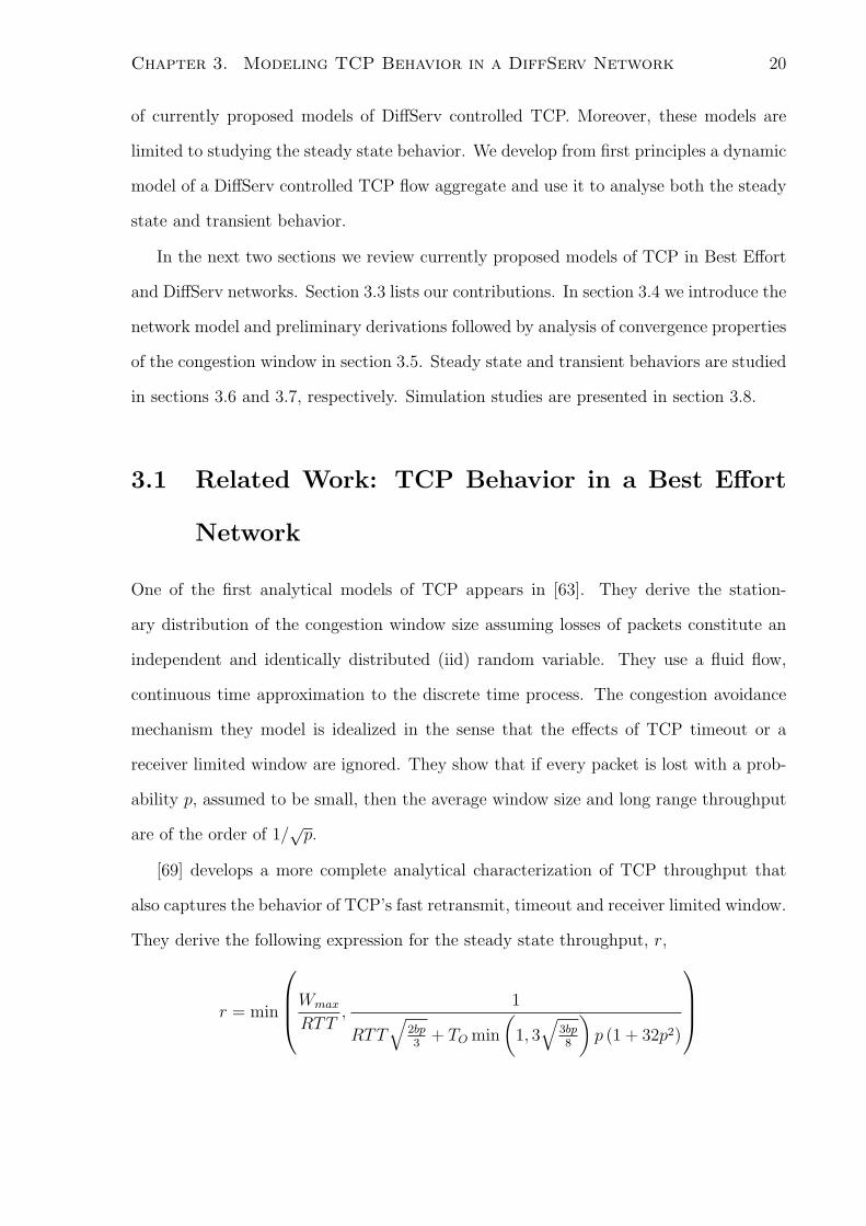
[85] considers the steady state throughput of a TCP flow when token bucket markers
are used at the network edge, and as a result the model accounts for the important
DiffServ network parameter token bucket size. Let B denote the token bucket size. For
an over-provisioned network they derive the bandwidth as
r =
(A+
√A2+ 6
prT2
)
2A ≤ 1
T
(√2(B + 1
pr
)+ 2√
2B
)
3A4
+3√
B+ 1pr
2√
2TA > 1
T
(√2(B + 1
pr
)+ 2√
2B
) (3.2)
This reduces to equation (3.1) when B = 0 and therefore similar conclusions can be
drawn. However, as the token bucket size is accounted for, they identify conditions under
which the achieved rate is sensitive to the choice of the bucket size and, determine what
profile rates are achievable and what are not. From their expressions for the bandwidth,
it can be seen that the condition
A >1
T
(√2
(B +
1
pr
)+ 2√
2B
)
leads to the case where the achieved rate is influenced by the choice of bucket size. This
condition refers to the case where the bucket size imposes a constraint, i.e., more tokens
are generated than can be stored in the bucket. On the other hand, whenever
A ≤ 1
T
(√2
(B +
1
pr
)+ 2√
2B
)
the achieved rate is not affected by the choice of bucket size.
[92] extends the work in [63] to derive the steady state throughput of a TCP aggregate
with n flows when token bucket markers are deployed at the network edge. They derive

Chapter 3. Modeling TCP Behavior in a DiffServ Network 26
Packet Drop Probability
Average Queue Length
100%50%30%
1.0
Out−of−Profile In−Profile
Figure 3.2: Non-Overlapping Drop Precedence Curves in a DiffServ Network
the bandwidth as
r =
(A+
√A2+ 6n2
prT2
)
2A ≤ 1
T
(√2(nB + n2
pr
)+ 2√
2nB
)
3A4
+3√
nB+n2
pr
2√
2TA > 1
T
(√2(nB + n2
pr
)+ 2√
2nB
) (3.3)
Even though the above equation is for a flow aggregation, this model fails to accurately
capture flow aggregation, which is central to DiffServ functionality. This is clearly evident
as this equation (3.3) can be derived from the equation (3.2), by adding the rate of n
separate flows with a contract rate equal to An
and a token bucket size of Bn.
[14] proposes a stochastic model of DiffServ controlled TCP based on a Markovian
fluid approach. They build a framework within which different token bucket variants
[101] are evaluated.
3.3 Our Contributions
All of the previous studies are limited to characterizing the steady state behavior. An-
other notable limitation is their primary focus being on a single TCP flow. As noted
earlier the model in [92], although it derives the rate of a TCP flow aggregate, it fails to
accurately capture flow aggregation.

Chapter 3. Modeling TCP Behavior in a DiffServ Network 27
We develop an analytical model from first principles and use it to analyse both the
steady state and transient TCP throughput in an over-provisioned DiffServ network.
We make the following contributions;
• We develop a model that intrinsically captures DiffServ flow aggregation. This
allows us to accurately measure the effect that the number of flows per aggregate
imparts on TCP throughput.
• Analyze convergence properties of the aggregate TCP congestion window size in
wide-ranging conditions. This provides insights to TCP congestion window’s oscil-
latory behavior.
• Study both the transient and steady state TCP behavior. We represent DiffServ
controlled TCP dynamics in a classical control system model. It allows use of
standard techniques to analyze various mechanisms and propose improvements to
algorithms as well as analysis-backed guidelines for choosing parameters of the
algorithms.
• Derive more complete expressions for excess bandwidth distribution in terms of
number of flows per aggregate, RTT, contract rate, and token bucket size.
3.4 The Network Model
In this section we introduce the network model. We consider a DiffServ network with
two color token bucket markers at the edge and a two drop precedence core. We confine
our study to an over-provisioned network.
The total congestion window size of aggregate a in the ith cycle is denoted by the
variable wa,i, where i ∈ Z∗. Each packet drop marks the renewal of a cycle. Da,i denotes
the drop in the window size in cycle (i), in response to a packet drop. Bi is the maximum
number of tokens accumulated in the bucket. We call Wa(= AaTa) the contract window

Chapter 3. Modeling TCP Behavior in a DiffServ Network 28
���������������������������������������������
���������������������������������������������
��������������������������
��������������������������
���������������������������������������������
���������������������������������������������
cycle i
wa,i−1
wv
a,i
wa,i+1^
i+1B
Da,i−1
w^
a,i
Da,i
Contract Window Size (Wa)
B
a,i−1wv
Aggregate Congestion Window
# RTT
a,i+1wv
a,im
cycle i−1 cycle i cycle i+1
Figure 3.3: The Aggregate TCP Congestion Window.
size of the ath aggregate, where Aa is the contract rate and Ta the Round-Trip-Time
(RTT) of flows belonging to that aggregate. Let wa,i and wa,i denote the deviation of
wa,i from Wa at the beginning and end of each cycle. The number of RTTs required for
wa,0 to reach wa,0 from Wa is denoted by ma,0. For subsequent cycles ma,i denotes the
number of RTTs per cycle. na denotes the number of flows of the ath aggregate and pg
and pr denote, respectively, the in-profile and out-of-profile packet dropping probabilities
at the core router. To simplify the analysis we make the following further assumptions.
1. Flows of each aggregate are TCP. We adopt an idealized TCP congestion avoidance
behavior. Each flow simply increases the congestion window by one per RTT in
the absence of any packet loss and halves the congestion window in response to a
packet loss, without invoking slow start or fast retransmit/recovery mechanisms.
2. RTTs of all flows within an aggregate are equal and constant (=Ta). Therefore the
increment in the total congestion window per RTT of an aggregate is na.

Chapter 3. Modeling TCP Behavior in a DiffServ Network 29
3. The core router has non-overlapping packet dropping curves for green and red
packets. This implies that pg = 0 and pr ≥ 0 as the network is over-provisioned.
We also assume that pr does not change over time.
4. Each aggregate gets through the number 1/pr of red packets before experiencing a
packet loss. This is actually the mean number of red packet transmissions between
consecutive packet losses [85]. If it is further assumed that packet drop events
constitute a Poisson process, then the standard deviation of this number is 1/√
pr ≪
1/pr for small pr. This leads to our deterministic model.
5. wa,i is shared equally among flows within that aggregate. This assumption simplifies
calculation of the reduction in wa,i in response to a packet loss.
If wa,i starts from below Wa (wa,i < 0), during the period wa,i < Wa the token bucket
generates more tokens than the number of packet arrivals. The token bucket stores up to
B excess tokens before tokens get discarded. Cycle (i−1) in Figure 3.3 illustrates a TCP
renewal cycle in which the token bucket overflows. When wa,i > Wa, the rate of packet
arrival exceeds the token generation rate, and therefore stored tokens are used. When
the token bucket is exhausted, it starts marking packets out-of-profile. This behavior is
represented by the following equations
wa,i−1 < 0,
w2a,i−1
2na
= B +1
pr
, (3.4)
Da,i−1 =Wa + wa,i−1
2na
,
=AaTa +
√2na(B + 1
pr)
2na
. (3.5)
In some cycles, the number of accumulated excess tokens is less than the size of the token
bucket. This prevents a token bucket overflow. The token bucket starts marking packets
out-of-profile earlier as a full bucket of tokens is not available. Cycle (i+1) in Figure 3.3

Chapter 3. Modeling TCP Behavior in a DiffServ Network 30
illustrates this situation. We have,
wa,i+1 < 0,
w2a,i+1
2na
= Bi+1 +1
pr
,
=w2
a,i+1
2na
+1
pr
, (3.6)
Da,i+1 =Wa + wa,i+1
2na
,
=AaTa +
√w2
a,i+1 + 2na
pr
2na
. (3.7)
In some other situations, for example cycle (i) in Figure 3.3, the congestion window drop
in response to a packet loss does not take the congestion window below Wa. No excess
tokens are generated in this case. This can be represented by the following equations,
wa,i > 0,
w2a,i
2na
=w2
a,i
2na
+1
pr
, (3.8)
Da,i =Wa + wa,i−1
2na
,
=AaTa +
√w2
a,i + 2na
pr
2na
. (3.9)
3.5 Aggregate TCP Congestion Window Behavior
We first consider the TCP renewal cycle for i = 0. During each RTT, wa,i increases by na.
Therefore, wa,0 = ma,0na. The number of packets generated in this cycle, for wa,0 > Wa
is equal to the total of in-profile packets generated at the contract rate, in-profile packets
generated (= B) because of the tokens accumulated during wa,0 ≤ Wa and 1/pr OUT
packets. Therefore we have,
1/pr + B =w2
a,0
2na
.
Chapter 3. Modeling TCP Behavior in a DiffServ Network 31
Solving for wa,0 gives
wa,0 =
√2na
(1
pr
+ B
). (3.10)
At the first packet loss, the drop of wa,0 is equal to
Da,0 =
AaTa +
√2na
(1pr
+ B)
2na
.
Different behaviors of wa,i are produced depending on the size of this reduction in wa,0.
3.5.1 Behavior 1
If the fall in the window in response to the first packet drop is at least the size of wa,0,
the next renewal cycle starts from below Wa, i.e. wa,1 < 0. This requires,
AaTa
2na
+
√1
2na
(1
pr
+ B
)≥
√2na
(1
pr
+ B
),
Aa ≥(2na − 1)
√2na
(1pr
+ B)
Ta
.
We have,
wa,1 ≤ 0,
=
(1− 1
2na
)√2na
(1
pr
+ B
)− AaTa
2na
.
Excess tokens are generated in this TCP renewal cycle. If it leads to a token bucket
overflow we have, wa,1 =
√2na
(1pr
+ B)
= wa,0. This results in wa,i = wa,0 for all i, i.e.
the aggregate congestion window converges to a limit cycle as depicted in Figure 3.4. A
token bucket overflow at the first renewal cycle requires,
w2a,1
2na
≥ B.
Therefore, we have
AaTa
2na
−(
1− 1
2na
)√2na
(1
pr
+ B
)≥√
2naB,

Chapter 3. Modeling TCP Behavior in a DiffServ Network 32
3900 3950 4000 4050 4100 4150 4200 4250 4300 4350
3500
3600
3700
3800
3900
4000
4100
4200
4300
time
aggr
egat
e co
nges
tion
win
dow
siz
e
Figure 3.4: The Aggregate TCP Congestion Window for A = 40000, pr = 0.2, n = 20,
B = 50, T = 0.1

Chapter 3. Modeling TCP Behavior in a DiffServ Network 33
Aa ≥(2na − 1)
√2na
(1pr
+ B)
+ 2na
√2naB
Ta
.
3.5.2 Behavior 2
Failure to overflow the token bucket during the first TCP renewal cycle means that it
accumulates B1 =w2
a,1
2na< B excess tokens while wa,1 ≤ Wa. In general, for cycle i,
assuming it accumulates Bi < B tokens while wa,i ≤ Wa, we have,
w2a,i = 2na
(1
pr
+ Bi
). (3.11)
Therefore,
wa,i ≤√
2na
(1
pr
+ B
)= wa,0 ∀i. (3.12)
We also have
w2a,i = w2
a,i −2na
pr
.
An upper bound on wa,i can be derived using the inequality (3.12), i.e.
w2a,i ≤ w2
a,0 −2na
pr
,
= 2naB ∀i. (3.13)
As the above inequality implies, the failure to overflow the token bucket in the first TCP
renewal cycle prevents any subsequent token bucket overflows. We have,
wa,i = wa,i−1
(1
2na
− 1
)+
Wa
2na
, (3.14)
w2a,i = w2
a,i +2na
pr
. (3.15)
We can prove that the sequence wa,i converges to a fixed point wa using the contraction
mapping theorem. From the above equations we get,
w2a,i =
[wa,i−1
(1− 1
2na
)− Wa
2na
]2
+2na
pr
.

Chapter 3. Modeling TCP Behavior in a DiffServ Network 34
Let
f(z) =
√[z
(1− 1
2na
)− Wa
2na
]2
+2na
pr
.
We have
f ′(z) =2[z(1− 1
2na
)− Wa
2na
](1− 1
2na)
2
√[z(1− 1
2n
)− Wa
2na
]2+ 2na
pr
,
<
[z(1− 1
2na
)− Wa
2na
](1− 1
2na)
[z(1− 1
2na
)− Wa
2na
] ,
< 1.
Therefore, from the Mean Value Theorem [42] we have,
|wa,i − wa,i−1| < K|wa,i−1 − wa,i−2|
where K < 1. It follows that f : I → I is a contraction and the contraction mapping
theorem [42] establishes the convergence of the sequence wa,i. Therefore values of Aa,
(2na − 1)
√2na
(1pr
+ B)
+ 2na
√2naB
Ta
> Aa >
(2na − 1)
√2na
(1pr
+ B)
Ta
lead to a congestion window trace as depicted in Figure 3.5.
3.5.3 Behavior 3
When
(2na − 1)
√2na
(1pr
+ B)
Ta
> Aa
the congestion window in the first TCP renewal cycle starts from above Wa. The con-
gestion window in the following TCP renewal cycles depends on the size of wa,1. If
wa,1 < wa,0, we can prove that wa,i is monotonically decreasing while wa,i ≥ 0. We have
w2a,1 = w2
a,1 +2na
pr
,
w2a,0 = 2naB +
2na
pr
.

Chapter 3. Modeling TCP Behavior in a DiffServ Network 35
2000 2100 2200 2300 2400 2500 2600 2700
1850
1900
1950
2000
2050
2100
2150
2200
time
aggr
egat
e co
nges
tion
win
dow
siz
e
Figure 3.5: The Aggregate TCP Congestion Window for A = 24000, pr = 0.2, n = 20,
B = 50, T = 0.1

Chapter 3. Modeling TCP Behavior in a DiffServ Network 36
1600 1700 1800 1900 2000 2100 2200
1560
1580
1600
1620
1640
1660
time
aggr
egat
e co
nges
tion
win
dow
siz
e
Figure 3.6: The Aggregate TCP Congestion Window for A = 16000, pr = 0.2, n = 20,
B = 50, T = 0.1
580 600 620 640 660 680 700 720 740560
580
600
620
640
660
time
aggr
egat
e co
nges
tion
win
dow
siz
e
Figure 3.7: The Aggregate TCP Congestion Window for A = 6000, pr = 0.2, n = 20,
B = 50, T = 0.1

Chapter 3. Modeling TCP Behavior in a DiffServ Network 37
Therefore, wa,1 < wa,0 requires
√2naB > wa,1 ≥ 0,
√2naB > wa,0 −
Wa + wa,0
2na
≥ 0.
Solving for Aa we get,
(2na − 1)
√2na
(1pr
+ B)
Ta
≥ Aa >
(2na − 1)
√2na
(1pr
+ B)− 2na
√2naB
Ta
. (3.16)
To prove that wa,i is monotonically decreasing we use the principle of mathematical
induction. We have the initial condition wa,1 < wa,0. We now make the induction
hypothesis, wa,k ≤ wa,k−1. wa,k and wa,k+1 are equal to,
wa,k = wa,k−1
(1− 1
2na
)− Wa
2na
,
wa,k+1 = wa,k
(1− 1
2na
)− Wa
2na
.
Therefore,
wa,k+1 − wa,k = (wa,k − wa,k−1)
(1− 1
2na
).
We have wa,k ≤ wa,k−1 from the induction hypothesis, hence wa,k+1 ≤ wa,k as the above
equation implies. To prove wa,k+1 ≤ wa,k we note that
w2a,i − w2
a,i =2na
pr
.
wa,k+1 ≤ wa,k implies wa,k+1 ≤ wa,k. Then by induction we have that wa,i+1 ≤ wa,i ∀i.
For some values of Aa within the above range, wa,i dips below Wa in its descent. This
complicates the congestion window behavior. When the congestion window dips below
Wa, the next TCP renewal cycle starts above the start of the previous TCP renewal cycle
because of excess tokens generated while wa,i < Wa. Therefore, this breaks the decrease
in the congestion window. Let wa = limi→∞ wa,i denote the equilibrium window size,

Chapter 3. Modeling TCP Behavior in a DiffServ Network 38
Equation (3.21), which is equal to
wa =−2na + (2na − 1)
√1 + 2na(4na−1)
A2aT 2
a pr
AaTa(4na − 1).
For values of,
Aa ≥(2na − 1)
√2na
pr
Ta
,
we have wa ≤ 0 and the congestion window dips below the contract window size. Figures
3.6 and 3.7 show the congestion window traces for two values of Aa in this range,
(2na − 1)
√2na
(1pr
+ B)
Ta
> Aa >(2na − 1)
√2na
pr
Ta
.
3.5.4 Behavior 4
When
(2na − 1)√
2na
pr
Ta
> Aa >
(2na − 1)
√2na
(1pr
+ B)− 2na
√2naB
Ta
,
the congestion window converges above Wa. The congestion window trace for a contract
rate in this range is depicted in the Figure 3.8.
3.5.5 Behavior 5
For
(2na − 1)
√2na
(1pr
+ B)− 2na
√2naB
Ta
≥ Aa
we have
wa,1 ≥ wa,0.
We can prove that wa,i converges by showing that the sequence wa,i is bounded and
monotonically increasing, which is sufficient for proving convergence [42]. We have that
wa,i ≤ 1/pr. To prove that wa,i is monotonically increasing we follow similar reasoning

Chapter 3. Modeling TCP Behavior in a DiffServ Network 39
430 440 450 460 470 480 490380
390
400
410
420
430
440
450
460
time
aggr
egat
e co
nges
tion
win
dow
siz
e
Figure 3.8: The Aggregate TCP Congestion Window for A = 4000, pr = 0.2, n = 20,
B = 50, T = 0.1

Chapter 3. Modeling TCP Behavior in a DiffServ Network 40
80 85 90 95 100
40
45
50
55
60
65
70
75
80
85
90
Figure 3.9: The Aggregate TCP Congestion Window for A = 500, pr = 0.2, n = 20,
B = 50, T = 0.1
to that presented in section 3.5.3. We have wa,1 > wa,0. From the induction hypothesis
we also have, wa,k ≥ wa,k−1. Then for i = k, k + 1, following from the analysis in section
3.5.3, we have,
wa,k+1 − wa,k = (wa,k − wa,k−1)
(1− 1
2na
).
From the above wa,k ≥ wa,k−1 implies that wa,k+1 ≥ wa,k. To prove wa,k+1 ≥ wa,k we note
that
w2a,i − w2
a,i =2na
pr
.
Therefore wa,k+1 ≥ wa,k implies wa,k+1 ≥ wa,k. Then by induction we have that wa,i+1 ≥
wa,i. Therefore the sequence wa,i converges ∀i, i.e. limi→∞ wa,i = wa, wa,i = wa and
wa,i = wa. Figure 3.9 shows the window trace for a value of Aa in this range.

Chapter 3. Modeling TCP Behavior in a DiffServ Network 41
3.6 Steady State Behavior
Having established the convergence properties of wa,i we now consider the steady state
behavior and derive the average rate of packet generation at steady state, r. Loss of
tokens occurs only during the first behavior of the five different TCP congestion window
behaviors considered above. For this particular congestion window behavior we have,
Wa + wa =
(1− 1
2na
)(Wa + wa) , (3.17)
B +1
pr
=w2
a
2na
. (3.18)
Solving for wa, wa we obtain,
wa =
√2na
(B +
1
pr
),
wa =
(1− 1
2na
)√2na
(B +
1
pr
)− Wa
2na
.
Therefore,
wa = Wa +wa + wa
2,
=
(1− 1
4na
)(AaTa +
√2na
(B +
1
pr
)),
r =wa
Ta
,
=
(1− 1
4na
)Aa +
√2na
(B + 1
pr
)
Ta
,
ma =wa − wa
na
,
=1
2n2a
√2na
(B +
1
pr
)+
Wa
2n2a
.
No tokens are lost for other values of the contract rate, given by
Aa ≤(2na − 1)
√2na
(1pr
+ B)
+ 2na
√2naB
Ta
.

Chapter 3. Modeling TCP Behavior in a DiffServ Network 42
We have,
Wa + wa =
(1− 1
2na
)(Wa + wa) , (3.19)
w2a
2na
+1
pr
=w2
a
2na
. (3.20)
Solving the above we get,
wa =−2naAaTa + (2na − 1)
√A2
aT2a + 2na(4na−1)
pr
(4na − 1), (3.21)
wa =−(2na − 1)AaTa + 2na
√A2
aT2a + 2na(4na−1)
pr
(4na − 1), (3.22)
wa =AaTa +
√A2
aT2a + 2na(4na−1)
pr
2, (3.23)
r =Aa +
√A2
a + 2na(4na−1)prT 2
a
2, (3.24)
ma =AaTa +
√A2
aT2a + 2na(4na−1)
pr
na(4na − 1). (3.25)
The above expressions for the aggregate TCP rate can be summarised as,
r =
Aa+
√A2
a+2na(4na−1)
prT2a
2Aa ≤
(2na−1)√
2na( 1pr
+B)+2na
√2naB
Ta(1− 1
4na
)(Aa +
√2na(B+ 1
pr)
T
)Aa >
(2na−1)√
2na( 1pr
+B)+2na
√2naB
Ta
For na = 1 this gives the same expression as in [85]. However, this deviates from that
of [92] as we model flow aggregation differently. From the equations, it can be seen that
the condition,
Aa >
(2na − 1)
√2na
(1pr
+ B)
+ 2na
√2naB
Ta
, (3.26)
leads to the case where the achieved rate is influenced by the choice of bucket size. If
B <
(Aa
na(4na − 1)
)2
Ta −1
pr
, (3.27)
TCP cannot reach the contract rate. Equation (3.27) indicates that a higher number of
flows per aggregate, lower RTT and lower contract rate can possibly compensate this.

Chapter 3. Modeling TCP Behavior in a DiffServ Network 43
On the other hand, when
Aa ≤(2na − 1)
√2na
(1pr
+ B)
+ 2na
√2naB
Ta
, (3.28)
the achieved rate exceeds the contract rate. Let re denote the excess bandwidth, which
is equal to
re =−Aa +
√A2
a + 2na(4na−1)prT 2
a
2.
Here we have,
∂re
∂Aa
= −0.5 +Aa
2√
A2a + 2na(4na−1)
prT 2a
,
∂re
∂na
=(16na − 1)
√A2
a + 2na(4na−1)prT 2
a
prT 2a
,
∂re
∂Ta
=−4na(4na − 1)
√A2
a + 2na(4na−1)prT 2
a
prT 3a
.
Therefore −0.5 < ∂re
∂Aa< 0, ∂re
∂na> 0, ∂re
∂Ta< 0. Excess bandwidth distribution favors lower
contract rate aggregates with many low delay connections. In practice a higher contract
rate aggregate is expected to carry more flows and therefore may offset any disadvantage
it inherits due to contract rate. Indeed, the effect of change in the number of flows is
more dominant according to the above partial derivatives. Figure 3.10 illustrates the
dependence of excess bandwidth distribution on contract rate, number of flows and RTT
for different values of packet drop probability.
3.6.1 Multiple Packet Drops
The above analysis assumes that 1/pr out-of-profile packets are transmitted between
each packet drop. This basically ignores concurrent packet drops. However, in realistic
network scenarios it is likely that packets belonging to multiple flows are dropped. This
triggers multiple flow back-offs. We incorporate this in our model by simply increasing

Chapter 3. Modeling TCP Behavior in a DiffServ Network 44
1000 2000 3000 4000 5000 60000
1000
2000
3000
4000
5000
6000
Minimum Guaranteed Rate (MGR) pkts/sec
Exc
ess
Ban
dwid
th (
pkts
/sec
)
p=0.02
p=0.05
p=0.1
p=0.4
p=0.8
10 20 30 40 50 600
2000
4000
6000
8000
10000
12000
Number of flows per aggregate
Exc
ess
Ban
dwid
th (
pkts
/sec
)
p=0.02
p=0.05
p=0.1
p=0.4
p=0.8
0.02 0.04 0.06 0.08 0.10
0.5
1
1.5
2
2.5
3x 10
4
Round Trip Time (sec.)
Exc
ess
Ban
dwid
th (
pkts
/sec
)
p=0.02
p=0.05
p=0.1
p=0.4
p=0.8
Figure 3.10: The Effect of Network Parameters on TCP Excess Bandwidth

Chapter 3. Modeling TCP Behavior in a DiffServ Network 45
the drop in the congestion window proportional to the number of flows affected by one
congestion epoch. Let h denote the number of flows affected. Therefore the steady state
TCP throughput for the first congestion window behavior considered above, which fails
to reach contract rates and is the most likely to experience concurrent packet drops due
to its large congestion window, is equal to
r =
(1− h
4n
)Aa +
√2na
(B + 1
pr
)
T
.
This is true for contract rates given by,
Aa >
(2na − h)
√2na
(1pr
+ B)
+ 2na
√2naB
Tah.
3.7 Transient Behavior
We use our deterministic model developed in the previous section to study TCP transient
behavior. For simplicity we confine our study to the congestion window behaviors in
which the TCP rate exceeds the contract rate. From equations (3.14),(3.15) we get
(2nawk+1 + Wa)2 − (2na − 1)2w2
k = (2na − 1)2 2na
pr
.
Considering small perturbations in pr, wk and wk+1 from the steady state condition, we
have,
δwk+1 =(2na − 1)2wa
2na(2nawa + Wa)δwk
− (2na − 1)2
2p2r(2nawa + Wa)
δpr. (3.29)
This is a first-order discrete-time system with a pole in the z-plane at
z0 =(2na − 1)2wa
2na(2naw + Wa).

Chapter 3. Modeling TCP Behavior in a DiffServ Network 46
Substituting for wa using (3.21) and simplifying, we get
z0 =−2na(2na − 1) + (2na − 1)2
√1 + 2na(4na−1)
W 2a pr
−2na(2na − 1) + (2na)2
√1 + 2na(4na−1)
W 2a pr
.
Mapping from the z-plane to the s-plane gives the corresponding continuous domain pole
as
s0 =1
maTa
ln(z0).
where ma is given by (3.25). The time-constant, denoted by τ is
τ = − 1
s0
= −maTa
ln(z0). (3.30)
For a TCP aggregate with one flow (na = 1) without DiffServ Control (Wa = 0), accord-
ing to the above deterministic model we have
ma =
√2
3pr
=2
3wa,
τ = −2
3wa
Ta
ln (1/4)=
waTa
2.08.
This differs slightly from the TCP time constant, τ = waTa
2, derived in [64] using a
stochastic model of TCP.
z0 becomes zero when
Aa =(2na − 1)
Ta
√2na
pr
,
and τ → 0 .This is the critical value of Aa in the condition (3.5.3) governing the transition
in the window behavior from one to two.
Mapping the discrete-time equation (3.29) to the continuous domain, we obtain the
continuous domain transfer function:
δwa(s)
δpr(s)=
g0
s− s0
, (3.31)
where
g0 = − s0na(2na − 1)
p2r
√W 2
a + 2na(4na−1)pr
.
Chapter 3. Modeling TCP Behavior in a DiffServ Network 47
Finally, the transfer function between the mean window size, wa, and the out-of-profile
packet dropping probability, pr, can be found from equation (3.31) using equations (3.21)
and (3.23) as
δwa(s)
δpr(s)=
g0
s− s0
(3.32)
where
g0 = −g0(4na − 1)
(1 +
√1 + 2na(4na−1)
prW 2a
)
2(−2na + (2na − 1)
√1 + 2na(4na−1)
prW 2a
) .
Equation (3.32) represents the generalisation of the TCP Reno model to TCP Reno with
Token Bucket rate regulation. Note that previous studies [25] have used the unmodified
TCP Reno transfer function in the DiffServ environment, which may have led to incorrect
parameter choices.
3.8 Simulation Studies
In this section we present ns-2 simulation studies that validate the TCP model developed
in the previous section.
We use a network topology, depicted in Figure 3.11, similar to the one used in [25].
TCP aggregates feed into a congested core with service differentiation ability. Each
TCP flow is running FTP [80] over TCP SACK. The start times of the flows are
uniformly distributed in [0,50] sec. The RED-In-Out (RIO) queue management tech-
nique [27] provides the differentiation ability at the core. It has minthreshin = 150,
maxthreshin = 300, minthreshout = 50, maxthreshout = 250, maxprobabilityin = 0.1, and
maxprobabilityout = 0.15. We use a packet size of 500 Bytes. Each edge has a token
bucket with a depth of 500 packets.

Chapter 3. Modeling TCP Behavior in a DiffServ Network 48
Bottleneck link
N1
Ni 100 Mbps[15−25] ms
100 Mbps [15−25] ms
DiffServ Domain
Senders
Receivers
100 Mbps, 5 ms
32 Mbps, 20ms
Aggregate i
100 Mbps 15 ms
15 ms100 Mbps
Figure 3.11: Modeling TCP Behavior: Simulation Network Topology
3.8.1 Experiment 1
In this experiment we study the effect of contract rate on the aggregate TCP rate. We
consider two TCP aggregates of which one aggregate has no contract rate. It emulates
background traffic. We vary the contract rate of the DiffServ controlled TCP aggregate.
Each aggregate consists of 30 flows. The propagation delays of access links are all uniform
in the range [15-25] ms. For each value of the contract rate we select the core link
capacity to provide 20 Mbps of excess bandwidth for background traffic. This minimizes
any change in the packet drop probability at the congested core as the contract rate
of the DiffServ controlled TCP aggregate is varied. Simulation results, average values
computed over 10 iterations, are presented in Figure 3.12. The inability of TCP to reach
contract rates is clearly evident. It fairly accurately predicts the TCP rate obtained
through simulations, in particular for contract rates where the TCP rate exceeds the
contract rate. For large values of the contract rate the simulation results follow increasing

Chapter 3. Modeling TCP Behavior in a DiffServ Network 49
0 5 10 15 20 25 30 35 400
5
10
15
20
25
30
35
40
Contract Rate (Mbps)
TC
P T
hrou
ghpu
t (M
bps)
simulationh=1h=2h=3h=4h=5h=6h=7
Figure 3.12: Model predicted aggregate TCP Rate for Different Contract Rates
number of concurrent packet drops. This is expected. As the contract rate increases, the
congestion window increases. This has the effect of more packet transmissions through
the congested core for the same level of feedback delay, which is likely to trigger multiple
packet drops.
3.8.2 Experiment 2
This studies the effect of number of flows per aggregate. We vary the number of flows
of the TCP aggregate which is DiffServ controlled. Simulation results, average values
computed over 10 iterations, are presented in Figure 3.13. As the model predicts, TCP
fails to reach contract rates as the number of flows per aggregate decreases. Simulation
results show a dip in the TCP throughput compared to model predictions for some
values. Instability of RED Queue Management is a main reason, as these particular
values correspond to increased oscillations of the instantaneous queue at the congested

Chapter 3. Modeling TCP Behavior in a DiffServ Network 50
0 2 4 6 8 10 12 14 16 18 2012
13
14
15
16
17
18
19
Number of Sources
TC
P T
hrou
ghpu
t (M
bps)
p=0.05,T=0.25secp=0.03,T=0.25secp=0.01,T=0.25secp=0.005,T=0.25secp=0.05,T=0.35secp=0.05,T=0.15secsimulation
Figure 3.13: Aggregate TCP Rate for Different Numbers of Flows per Aggregate
router.
3.8.3 Experiment 3
In this simulation study we consider three DiffServ controlled TCP aggregates. Unless
otherwise specified each aggregate has a contract rate equal to 8 Mbps, and carries 30
TCP flows. The access links have a delay of 15 msec. We study the change in the
rate of packet transmission as network parameters of the aggregates are changed. We
perform four experiments each with a different set of aggregates. We plot the one second
average rate of packet transmission seen at each edge. Simulation results are in Figure
3.14. According to the model token loss is absent for the chosen network parameters.
We calculate pr, assuming a fully utilized core link:
3∑
i=1
Ai +√
A2i + 2ni(4ni−1)
prT 2i
2= C,

Chapter 3. Modeling TCP Behavior in a DiffServ Network 51
and compute the rate of packet transmission at each edge according to,
ri =Ai +
√A2
i + 2ni(4ni−1)
prT 2i
2.
First we set the contract rate of each aggregate such that, A1=4 Mbps, A2=8 Mbps,
A3=12 Mbps. As predicted from the model, the lowest contract rate aggregate receives
the largest share of excess bandwidth when all the aggregates have the same number of
flows and the model accurately predicts the actual rate of packet transmission of each
aggregate. Next we change the number of flows of each aggregate such that N1=45,
N2=30, N3=15. As expected the aggregate with the largest number of flows grabs the
largest share of excess bandwidth. Now we change the access links’ delay. Again the
model accurately predicts the rates of packet transmission. Previous studies, which did
not account for the presence of multiple flows per aggregate, have reported the bias of
excess bandwidth distribution as being toward lower contract rate aggregates. This has
created the presumption that the highest contract rate aggregate receives the smallest
share of excess bandwidth regardless of the number of flows it carries. As we pointed out
earlier an increase in contract rate is usually accompanied by an increased number of flows
sharing that aggregate. Finally we consider this particular scenario. The contract rates
of the aggregates are chosen proportional to the number of flows. We have A1=12 Mbps,
A2=8 Mbps, A3=4 Mbps, N1=45, N2=30, and N3=15. As our model predicts, defying
the common belief, the first aggregate receives the largest share of excess bandwidth
despite having the largest contract rate. The effect of the change in number of flows
dominates.

Chapter 3. Modeling TCP Behavior in a DiffServ Network 52
0 50 100 150 2000
5
10
15
20
25
A1=12 Mbps, A
2=8 Mbps, A
3=4 Mbps
Time (seconds)
Sen
ding
rat
e (M
bps)
0 50 100 150 2000
5
10
15
20
25
(Ni, A
i Mbps) {(45,12), (30,8), (15,4)} for i=1,2,3
Time (seconds)
Sen
ding
rat
e (M
bps)
0 50 100 150 2000
5
10
15
20
25
N1=45, N
2=30, N
3=15
Time (seconds)
Sen
ding
rat
e (M
bps)
0 50 100 150 2000
5
10
15
20
T1=0.12, T
2=0.15, T
3=0.18 sec.
Time (seconds)
Sen
ding
rat
e (M
bps)
Figure 3.14: Aggregate TCP Rate for Different Network Parameters

Chapter 4
Improving TCP Behavior in a
DiffServ Network
4.1 Related Work
Early network traffic measurement research [23] showed that TCP was the dominant
protocol on the Internet in the early 1990’s. Several recent and popular Internet appli-
cations, such as multimedia streaming, IP telephony, and multicast, rely predominantly
on the User Datagram Protocol (UDP) rather than TCP, and may gradually shift the
balance of traffic away from TCP. However, the measurements presented in [95] suggest
that TCP is still the dominant traffic force on the Internet, and is likely to remain so
for the foreseeable future. The primary reason is the advent of the World Wide Web:
the growing number of Internet users, the widespread availability of easy-to-use Web
browsers, and the proliferation of Web sites with rich multimedia content combine to
contribute to the exponential growth of Internet TCP traffic. Web caching and content
distribution networks help to soften this impact, but the overall growth is still dramatic.
Given this widespread deployment of TCP, the inability of DiffServ controlled TCP to
reach contract rates in realistic network conditions [85, 102, 14, 92, 13] is an impediment
53

Chapter 4. Improving TCP Behavior in a DiffServ Network 54
for successful deployment of DiffServ. This has motivated several studies [101, 94, 25].
[101] consider modifying (a) the dropping policies at the core router, (b) the marking
strategies at the meter and (c) the transport protocol at the sender. They propose
modifying the core router packet drop probability to be inversely proportional to the
contract rate. The packet drop probability is calculated as
p = k/(mk + ri/rmin)
where k,m and rmin are suitably chosen constants. rmin is the smallest contract rate. m
is chosen based on the target drop probability for a flow with zero reservation. Similarly,
the parameter k is chosen based on the target drop probability required for the flow
with rmin reservation. The DiffServ architecture does not associate any packet with a
specific flow or aggregate inside the network core. Moreover, core routers are unaware
of each aggregate’s contract rate. Therefore, this modification requires changes to the
DiffServ architecture. It can also potentially impair DiffServ scalability properties. At
the meter they propose a three drop precedence packet marking much like the TRTCM
marker proposed in [45]. Apart from the extra burden of tuning new parameters, it is also
largely dependent on the performance of multi level AQMs of core routers. It is extremely
difficult to tune RED, the AQM most DiffServ core routers deploy, or any other AQM
technique to operate without any considerable fluctuations in the queue length. RED
invariably exhibits oscillations and that renders a three drop precedence ineffective. They
also propose to modify the sender to react differently depending on the lost packet’s level
of conformance. Within the DiffServ architecture there is no feedback mechanism for the
sender to infer the level of conformance its packets receive. Therefore, this modification
demands changes at the DiffServ architectural level similar to their proposed changes in
the core routers.
Recently, [25] introduced an Active Rate Management (ARM) mechanism. The basic
idea is that the edge routers maintain ARMs which are responsible for adaptively setting
token bucket rates in order to achieve contract rates in the face of changing network

Chapter 4. Improving TCP Behavior in a DiffServ Network 55
parameters. This is achieved through a feedback structure around a token bucket. The
aim of ARM is to regulate the token bucket rate such that aggregate rates converge to
the contract rates. ARM compares the aggregate input rate to its contract rate. Though
with ARM throughputs converge to contract rates in an exact-provisioned network, in an
over-provisioned network the need to exceed contract rates creates a dilemma, namely a
persistent non-zero control loop error at the desired network equilibrium. To overcome
this drawback, [25] complicates the simple feedback structure such that some of the
ARMs deactivate and rely on the native TCP congestion control protocol to regulate the
throughput in excess of the contract rate. As most networks would be over-provisioned
due to admission control actions, this would be a common occurrence. Ironically this
change to make ARM feasible in an over-provisioned network introduces adverse compli-
cations. The ARMs that remain active in an over-provisioned network have their rates
locked at the contract rates while the deactivated ARMs grab the excess bandwidth. This
disparity in excess bandwidth distribution is not seen with the classical token bucket
markers. Furthermore, inactive ARMs mark all packets as out-of-profile regardless of
their contract rates. Though other ARMs continue marking packets as in-profile, they
operate at below the contract rate. Moreover, the information a marked packet carries
may not only be used for rate regulation in a DiffServ network. For example, it may
also be used to determine the mark a packet carries once it enters a neighboring DiffServ
domain, i.e. domains need to trust each other. It could also be used to give in-profile
packets other preferential treatments like low latency queuing. Therefore the loss of this
information greatly limits DiffServ functionality. Deployment of ARM also requires ma-
jor changes in the network core as it requires core routers to do ECN marking instead
of dropping packets to signal network congestion. As a consequence, end nodes need
to be ECN capable. As the aggregates rate of packet arrivals is compared to contract
rate in the controller, any subsequent packet drops inside the network core over-estimate
actual rate of packet transmissions and can possibly prevent TCP aggregates from reach-

Chapter 4. Improving TCP Behavior in a DiffServ Network 56
ing their contract rates. In a traditional DiffServ network core out-of-profile packets are
dropped before any in-profile packets are marked or dropped. Otherwise, for example
in a correctly provisioned network out-of-profile packet transmissions may use the net-
work bandwidth large enough only to accommodate in-profile packets generated at the
contract rate.
Another proposal aimed at solving TCP issues in a DiffServ network is TB-REM [94].
It modifies the token bucket such that it proactively signals a depleting token bucket
by marking packets out-of-profile before the token bucket becomes completely empty.
Basically it avoids too many flows simultaneously responding to network congestion,
conceptually similar to RED functionality. In fact this kind of behavior is expected from
an idealized core router, so TB-REM can be thought of as aiding core router functionality.
Our analysis in the previous chapter which assumed an idealized core router established
the failure of TCP flow aggregates to reach contract rates. Therefore a mechanism
that just aids core router functionality simply cannot prevent TCP flows falling short
of contract rates. The marking of packets with a non-empty token bucket can actually
increase the likelihood of a token bucket overflow, which is precisely what should be
avoided. For example a half-full token bucket only takes half the time to overflow for the
same drop in the congestion window as compared to an empty token bucket.
4.2 Our Contributions
None of the techniques proposed so far provides an effective solution that aligns with the
DiffServ architecture. We propose two algorithms that are scalable and effective. More
importantly they can be incrementally deployed without any changes to the DiffServ
architecture. Our contributions are as follows;
• We investigate the benefits of using a packet queue at the token bucket. According
to our analysis in Chapter 3 the required size of the token bucket grows exponen-

Chapter 4. Improving TCP Behavior in a DiffServ Network 57
tially with the contract rate. We show that a packet queue needs to be only linearly
proportional to the contract rate to prevent TCP flow aggregates falling short of
contract rates.
• We propose improvements to ARM. We show that the ARM’s performance can be
drastically improved by comparing the rate of only in-profile packet transmissions
to the contract rate as opposed to using the total rate of packet transmissions. This
modification also simplifies network dynamics. It allows us to develop a network
model in which standard techniques are applied for choosing optimal Proportional
Integral (PI) controller parameters of the feedback controller.
In the next section, we introduce our first algorithm, Token Bucket with Queue
(TBQ). Its analysis is given in section 4.3.1. Section 4.3.2 proposes an improved ver-
sion of TBQ. Simulation studies that compare TBQ to classical token bucket are pre-
sented in section 4.3.3. An improved version of ARM, termed Continuous Active Rate
Management (CARM), is detailed in section 4.4 followed by its associated simulation
studies.
4.3 Token Bucket and a Queue
Our analysis in Chapter 3 reveals that TCP flow aggregates fail to reach contract rates
when tokens are lost and any subsequent out-of-profile packet transmissions fail to com-
pensate for the lost tokens. As the rate of packet transmissions drop in response to a
congestion event the token buckets are likely to overwhelm with excess tokens leading to
an overflow. Our proposed mechanism tries to avoid this by inflating the congestion win-
dow over its normal equilibrium value. To achieve this we use a finite sized packet queue
at the token bucket that holds packets arriving at an empty bucket. In the classical token
bucket marker, for example the SRTCM, when a packet arrives at an empty bucket, the
arriving packet is marked out-of-profile. That behavior in our scheme is changed such
Chapter 4. Improving TCP Behavior in a DiffServ Network 58
that the packet is instead held in a queue. Packets are marked out-of-profile only if an
arriving packet encounters a full queue. The arriving packet is held in the queue by re-
leasing, marked out-of-profile, the packet at the head of the queue. Otherwise, packets in
the queue are released, marked in-profile as tokens become available. While the queue is
being filled with packets, no out-of-profile packets are generated. Therefore the contract
window size is equal to the congestion window size during this period. However, once the
queue reaches its capacity and as each arriving packet dequeues the packet at the head of
the queue, packets are drained from the queue faster and as a result decreases the RTT.
This in turn decreases the contract window size. This delayed generation of out-of-profile
packets effectively inflates the congestion window. As a result the congestion window in
response to a congestion event does not drop as much as without TBQ. This prevents
the possibility of a token bucket overflow. Our algorithm improves TCP performance at
the expense of an increase in the RTT experienced by some packets. Such an impact on
latency is not significant for the type of traffic relying on AF PHB. For this type of traffic
the ability to reach contract rates is much more important. In fact the increase in latency
can potentially be used to the advantage for TCP. Within the DiffServ architecture a
sender is unaware of the marked profile of its packets. The increase in latency effected by
TBQ can potentially be used to infer a particular flow’s packets exceeding contract rates.
Many service providers offer capped data rates. TBQ can also be used very effectively in
this scenario. When used in that context, each arriving packet at an empty token bucket
and a full queue is simply dropped. With TBQ, TCP flows can maintain a rate close to
the allowed maximum rate. Moreover, the increase in queuing delay can also be used as
a congestion signal. A pseudo code representation of TBQ is given in Algorithm 4.3.1.

Chapter 4. Improving TCP Behavior in a DiffServ Network 59
Algorithm 4.3.1: TBQ(A,BT , BP )
comment: At the arrival of packet k
if (Queue is empty)
then
if (tokens > packet size)
then
{Mark the packet in-profile and release.
else
then
{Hold the packet.
else if (Queue is not full)
then
{Hold the packet.
else
then
Mark the packet at the head of
the queue out-of-profile and release.
Hold the arriving packet.
while (Queue is not empty)
then
A timer is pending.
At the expiration if tokens generated
exceed the size of the packet at the head of the queue,
mark it in-profile and release.
4.3.1 Network Model and Analysis
We adopt a very similar network model as used for modeling TCP behavior in a DiffServ
network in Chapter 3.
We consider an over-provisioned DiffServ network with single rate two color token

Chapter 4. Improving TCP Behavior in a DiffServ Network 60
buckets at the edge and a two drop precedence core. Figure 4.1 depicts a TCP renewal
cycle at steady state with TBQ. Let ma denote the number of RTTs for this TCP renewal
cycle. The total congestion window size of aggregate a is denoted by the variable wa,i,
where i ∈ [0,ma]. We call Wa,i(= AaTa,i) the contract window size of the ath aggregate,
where Aa is the contract rate and Ta,i the round-trip-time (RTT) of flows belonging to
that aggregate. Unlike the analysis in section 3.4, Ta,i is no longer considered a constant.
Let Ta denote the component of RTT assumed to be constant that excludes the increase
in RTT introduced by delayed packet transmissions in TBQ. Let Wa = AaTa. wa and wa
denotes the deviation of wa,i from Wa at the beginning and end of each cycle. na denote
the number of flows of the ath aggregate and pg and pr denote, respectively, the in-profile
and out-of-profile packet dropping probabilities at the core router. Token bucket depth
is equal to B. TBQ is capable of holding up to BP packets. We consider TCP steady
state behavior for
Aa >
(2na − 1)
√2na
(1pr
+ B)
+ 2na
√2naB
Ta
,
in which TCP flows fail to reach contract rates. To simplify the analysis we make the
following further assumptions as in section 3.4 of Chapter 3.
1. Flows of each aggregate are TCP. We adopt an idealized TCP congestion avoidance
behavior. Each flow simply increases the congestion window by one per RTT in
the absence of any packet loss and halves the congestion window in response to a
packet loss, without invoking slow start or fast retransmit/recovery mechanisms.
2. All flows experience the same RTT (=Ta). Therefore the increment in the total
congestion window per RTT of an aggregate is na.
3. The core router has non-overlapping packet dropping curves for green and red
packets. This implies that pg = 0 and pr ≥ 0 as the network is over-provisioned.
We also assume that pr does not change over time.

Chapter 4. Improving TCP Behavior in a DiffServ Network 61
��������������������������������������������������������������������������������
��������������������������������������������������������������������������������
��������������������������������������������������������������������������������������������������������������������������������������������
��������������������������������������������������������������������������������������������������������������������������������������������
Out−of−profilepackets
W^
2nB
BP
I1 I2 I3 I4
N
Wa=ATa
# RTT
Window Size
Wv
Figure 4.1: The Aggregate TCP Congestion Window
4. Each aggregate gets through a total of 1/pr of red packets before experiencing a
packet loss. This is actually the mean number of red packet transmissions between
consecutive packet losses [85].
5. wa,i is shared equally among flows within that aggregate. This assumption simplifies
calculation of the reduction in wa,i in response to a packet loss.
To simplify the analysis the TCP renewal cycle is partitioned as shown in Figure 4.1.
We have wa,i∈I1 ≤ Wa and as a result the token bucket generates more tokens than
packet arrivals and the token bucket is filled with excess tokens. We have wa,i∈I2 > Wa.
However, the queue remains empty as tokens accumulated previously continue marking
packets in-profile. For i ∈ I3, packets are enqueued as some arriving packets see an
empty token bucket. We have Ta,i∈I3 ≤ Ta + BP /Aa and Wa,i∈I3 = wa,i∈I3 . Once the
queue reaches its capacity each arriving packet triggers a dequeue. We have
wa,i∈I4 ≥ AaTa + BP .
If BP <√
2naB, the token bucket has enough excess tokens to continue generating in-

Chapter 4. Improving TCP Behavior in a DiffServ Network 62
profile packets past wa,i = AaTa + BP and as a result, delays the queue from reaching
its capacity. The queue is drained at a rate faster than the token generation rate when
packets at the head of the queue are released and marked out of profile, in order to
accommodate packets arriving at an empty token bucket. Indeed, it drains at the packet
arrival rate. Let r denote the rate at which packets are drained from the queue. Since
the maximum window size is Wa + wa, and the round trip time is bounded below by Ta
we have
r <wa + Wa
Ta
. (4.1)
We also have
wa < 0.
This requires, from Equation (3.4),
1
2na
(Wa + wa) > wa,
wa <Wa
2na − 1. (4.2)
From equations (4.1) and (4.2) we have that
r <2na
2na − 1Aa.
With the upper bound of r derived above, we have
Ta,i∈I4 > Ta +(2na − 1)BP
2naAa
,
Wa,i∈I4 > AaTa +(2na − 1)BP
2na
.
This can be used to derive an upper bound on the number of generated out-of-profile
packets, N , as depicted in Figure 4.1.
N =
[(wa−BP )
na
] [(wa − (2na−1)BP
2na
)+(BP − (2na−1)BP
2na
)]
2
=(wa −BP )
(wa − (na−1)BP
na
)
2na
.

Chapter 4. Improving TCP Behavior in a DiffServ Network 63
1pr
out-of-profile packets are generated per TCP renewal cycle. Therefore we have,
1
pr
≤(wa −BP )
(wa − (na−1)BP
na
)
2na
.
Simplifying we get,
wa ≥(2na − 1)
na
BP +
√B2
P
n2a
+8na
pr
. (4.3)
The number of tokens accumulated for i ∈ I1 is equal to,
w2a
2na
.
Specifically, if this is contained below the token bucket size, the loss of tokens is avoided.
We need
w2a
2na
≤ B. (4.4)
We have
Wa − wa = (Wa + wa)
(1− 1
2na
),
wa =Wa
2na
− wa
(1− 1
2na
). (4.5)
From equations (4.4) and (4.5) we get,
[Wa
2na
− wa
(1− 1
2na
)]2
≤ 2naB,
wa ≥ATa −
√8n3B
(2na − 1). (4.6)
As implied by equations (4.3) and (4.6), to prevent any token loss BP should be chosen
to satisfy
(2na − 1)
na
BP +
√B2
P
n2a
+8na
pr
≥ ATa −√
8n3B
(2na − 1). (4.7)
For example
BP =ATa −
√8n3B
2(2na − 1), (4.8)

Chapter 4. Improving TCP Behavior in a DiffServ Network 64
prevents any token loss, and as a consequence TCP flows achieve their contract rates.
The dependence of BP on A is approximately linear. Interestingly, the token bucket
depth can also be made zero without materially affecting the performance. Usually the
token bucket does not keep track of the number of flows per aggregate. Therefore, a
more conservative choice of BP that is invariant to the number of flows can be obtained
by choosing n = 1;
BP =ATa −
√8B
2.
4.3.2 Low Delay Packet Marker
One of the drawbacks of TBQ is the imposed requirement for delayed transmission of
some packets. The target traffic profile of AF PHB, mainly transactional TCP flows, does
not have stringent delay requirements. It is mostly UDP flows, which form multimedia
sessions that are sensitive to any increase in latency. This type of traffic relies on EF
PHB. Therefore it is unlikely that the increase in queuing delay affected by TBQ adversely
affects applications relying on AF PHB. Nevertheless, it is possible to further refine the
marker in terms of reducing queuing delay.
From equation (4.8) it is clear that an idealized core router at the presence of many
flows per aggregate significantly reduces the required size of the packet queue. The
above proposed algorithm can generate bursts of out-of-profile packets. Given that it is
extremely difficult to rely on the core router to realize the benefits of many flows per
aggregate, we propose probabilistic packet marking much like in TB-REM to aid the core
router to realize the advantage of multiple flows. We use a marking scheme very similar to
that used in RED [38]. At the arrival of each packet, the packet at the head of the queue is
marked out-of-profile and released with a probability determined by the queue length. For
simplicity we use the instantaneous queue length rather than an exponentially averaged
value as in RED. Also, we mark the DSCP rather than dropping or marking the ECN bit.
With RED, every mark or drop is an indication of network congestion and signals flows to

Chapter 4. Improving TCP Behavior in a DiffServ Network 65
slow down. Therefore the probability of packet marking/dropping needs to be kept low.
The RED curve has a discontinuity, at which the marking probability jumps to one from
a fairly small value. The queue stabilizes around a point away from this discontinuity. In
our scheme, marking the packet out-of-profile only increases the likelihood of a flow rate
reduction when the network is congested. Thus we choose a scheme in which the marking
probability, beyond a threshold called MinThresh, increases linearly all the way from zero
to one as the queue reaches capacity. When the queue length is below MinThresh, an
arriving packet does not trigger marking out-of-profile the packet at the head of the
queue. One of the most important and influential parameters is the MinThresh. On one
hand, a small threshold decreases the average queue length at the marker and cuts down
delay but, on the other hand, it is an indication of many flows and therefore has the
risk of overestimating the number of flows, which usually continues varying. Its influence
in RED is also critical as it trades off delay with link utilization. More generally the
parameter target queue length, in other AQMs such as REM [5], PI [47] has a similar
effect. Interestingly, studies on the choice of this critical parameter in different contexts
are quite limited. The presence of different varieties of congestion avoidance schemes as
well as the increased number of short-lived flows hinder such an investigation. A pseudo
code of this low delay marker is presented in algorithm 4.3.2.
It is the presence of multiple flows that made possible this low delay variant. That
dependence makes it less robust. However if the number of flows can be estimated, this
weakness can be eliminated by an adaptive marker, which adjusts the minimum threshold
as the number of flows change.
4.3.3 Simulation Studies - TBQ
In this section we present ns-2 simulation studies that compare TBQ to the classical
token bucket. The network topology is shown in Figure 4.2. TCP aggregates feed into a
congested core with service differentiation ability. Each TCP flow is running FTP over

Chapter 4. Improving TCP Behavior in a DiffServ Network 66
Algorithm 4.3.2: Low Delay TBQ(A,BT , BP ,MinThresh)
comment: At the arrival of packet k
if (Queue is empty)
then
if (tokens > packet size)
then
{Mark the packet in-profile and release.
else
then
{Hold the packet.
else if (Queue length is less than MinThreshold)
then
{Hold the packet.
else if (Queue is not full)
then
compute packet marking probability p.
if (Uniform[0, 1] < p)
then
Mark the packet at the head of
the queue out-of-profile and release.
Hold the arriving packet.
else
then
{Hold the packet.
else
then
Mark the packet at the head of
the queue out-of-profile and release.
Hold the arriving packet.
while (Queue is not empty)
then
A timer is pending.
At the expiration if tokens generated
exceed the size of the packet at the head of the queue,
mark it in-profile and release.

Chapter 4. Improving TCP Behavior in a DiffServ Network 67
Bottleneck link
N1
Ni 100 Mbps
100 Mbps
DiffServ Domain
Senders
Receivers
100 Mbps, 5 ms
32 Mbps, 20ms
Aggregate i
100 Mbps 15 ms
15 ms100 Mbps
p1
Tpi
T
Figure 4.2: TBQ Performance: Simulation Network Topology
TCP SACK. The start times of the flows are uniformly distributed in [0,50] sec. The
RIO queue management technique [27] provides the differentiation ability at the core.
It has minthreshin = 150, maxthreshin = 300, minthreshout = 50, maxthreshout = 250,
maxprobabilityin = 0.1, and maxprobabilityout = 0.15. We used a packet size of 500
Bytes. Each edge router has a token bucket marker with a depth of 50 packets. TBQ
uses a token bucket with a depth of 20 packets and a 30 packets long packet queue.
Experiment 1
In the first experiment we compare the performance of TBQ and the token bucket for
different contract rates. We consider two TCP aggregates of which one aggregate has no
contract rate. It emulates background traffic. We vary the contract rate of the DiffServ
controlled TCP aggregate. Each aggregate consists of 30 flows. The propagation delays of
access links Tpi are all uniform in the range [15-25] ms. For each value of the contract rate
we select the core link capacity to provide 20 Mbps of excess bandwidth for background

Chapter 4. Improving TCP Behavior in a DiffServ Network 68
0 5 10 15 20 25 30 35 400
5
10
15
20
25
30
35
40
Contract Rate (Mbps)
TC
P T
hrou
ghpu
t (M
bps)
TBQClassical TB
Figure 4.3: TBQ Performance for Different Values of A.
traffic. This minimizes any change in the packet drop probability at the congested core as
the contract rate of the DiffServ controlled TCP aggregate is varied. Simulation results
are presented in Figure 4.3. The Figure clearly shows the marked improvement the packet
queue of TBQ generates.
The remainder of the simulation studies have three TCP aggregates with non-zero
contract rates. The propagation delays Tpi are all uniform in the ranges: Tp1 ∈ [50− 90]
msec, Tp2 ∈ [15 − 25] msec and Tp3 ∈ [0 − 10] msec. Each sender consists of Ni FTP
flows, all starting uniformly in [0, 50] sec, with N1 = 20, N2 = 30 and N3 = 25. The edge
routers have contract rates equal to 8 Mbps, 2 Mbps and 5 Mbps. For TBQ we use 64,
16 and 40 packets long queues, proportional to their contract rates. The token bucket
depth is chosen such that the total of packet queue length and the token bucket depth
is 50 packets. The classical token bucket depth is 50 packets. The parameter settings
remain fixed in all experiments.

Chapter 4. Improving TCP Behavior in a DiffServ Network 69
0 50 100 150 2000
2
4
6
8
10
Time (seconds)
Sen
ding
rat
e (M
bps)
Classical TB − Total packet rate
Aggregate 1Aggregate 2Aggregate 3
0 50 100 150 2000
2
4
6
8
10
Time (seconds)
Sen
ding
rat
e (M
bps)
Classical TB − In−profile packet rate
Aggregate 1Aggregate 2Aggregate 3
0 50 100 150 2000
2
4
6
8
10
Time (seconds)
Sen
ding
rat
e (M
bps)
TBQ − Total packet rate
Aggregate 1Aggregate 2Aggregate 3
0 50 100 150 2000
2
4
6
8
10
Time (seconds)
Sen
ding
rat
e (M
bps)
TBQ − In−profile packet rate
Aggregate 1Aggregate 2Aggregate 3
Figure 4.4: TBQ Performance in an Exact-Provisioned Network
Experiment 2
In this experiment we compare the dynamics of TBQ and the classical token bucket for
an exact-provisioned network, i.e the core link capacity is 15 Mbps. Figure 4.4 presents
simulation results. With just the token bucket the TCP aggregate with the highest
contract rate fails to reach its contract rate. On the other hand its rate is very close to
contract rate with TBQ.

Chapter 4. Improving TCP Behavior in a DiffServ Network 70
0 50 100 150 2000
2
4
6
8
10
Time (seconds)
Sen
ding
rat
e (M
bps)
Classical TB − Total packet rate
Aggregate 1Aggregate 2Aggregate 3
0 50 100 150 2000
2
4
6
8
10
Time (seconds)
Sen
ding
rat
e (M
bps)
Classical TB − In−profile packet rate
Aggregate 1Aggregate 2Aggregate 3
0 50 100 150 2000
2
4
6
8
10
Time (seconds)
Sen
ding
rat
e (M
bps)
TBQ − Total packet rate
Aggregate 1Aggregate 2Aggregate 3
0 50 100 150 2000
2
4
6
8
10
Time (seconds)
Sen
ding
rat
e (M
bps)
TBQ − In−profile packet rate
Aggregate 1Aggregate 2Aggregate 3
Figure 4.5: TBQ Performance in a 20% Over-Provisioned Network
Experiment 3
We repeat the same experiment as above except for an increase of 20% in the core
router egress capacity making the network over-provisioned. The simulation results are
presented in Figure 4.5. Again with the token bucket the TCP aggregate with the highest
contract rate fails to reach its contract rate while with TBQ it exceeds its contract rate.
Experiment 4
We now consider an under-provisioned network. The experimental setup is identical to
Experiment 1 except for a 20% decrease in the core router egress capacity. Simulation

Chapter 4. Improving TCP Behavior in a DiffServ Network 71
0 50 100 150 2000
2
4
6
8
10
Time (seconds)
Sen
ding
rat
e (M
bps)
Classical TB − Total packet rate
Aggregate 1Aggregate 2Aggregate 3
0 50 100 150 2000
2
4
6
8
10
Time (seconds)
Sen
ding
rat
e (M
bps)
Classical TB − In−profile packet rate
Aggregate 1Aggregate 2Aggregate 3
0 50 100 150 2000
2
4
6
8
10
Time (seconds)
Sen
ding
rat
e (M
bps)
TBQ − Total packet rate
Aggregate 1Aggregate 2Aggregate 3
0 50 100 150 2000
2
4
6
8
10
Time (seconds)
Sen
ding
rat
e (M
bps)
TBQ − In−profile packet rate
Aggregate 1Aggregate 2Aggregate 3
Figure 4.6: TBQ Performance in a 20% Under-Provisioned Network
results are presented in Figure 4.6. Both schemes, TBQ and the classical token bucket
perform similarly.
Experiment 5
In this experiment we evaluate the performance impact of background traffic. Short-lived
TCP sessions with random size data transfers, Pareto distributed with a shape of 1.5 and
a mean of 500 Kbytes, traverse through the congested core. The starting times of these
sessions are exponentially distributed with a 1 second average time between arrivals.
These flows have round trip propagation delays uniformly distributed in [70,90] msec.
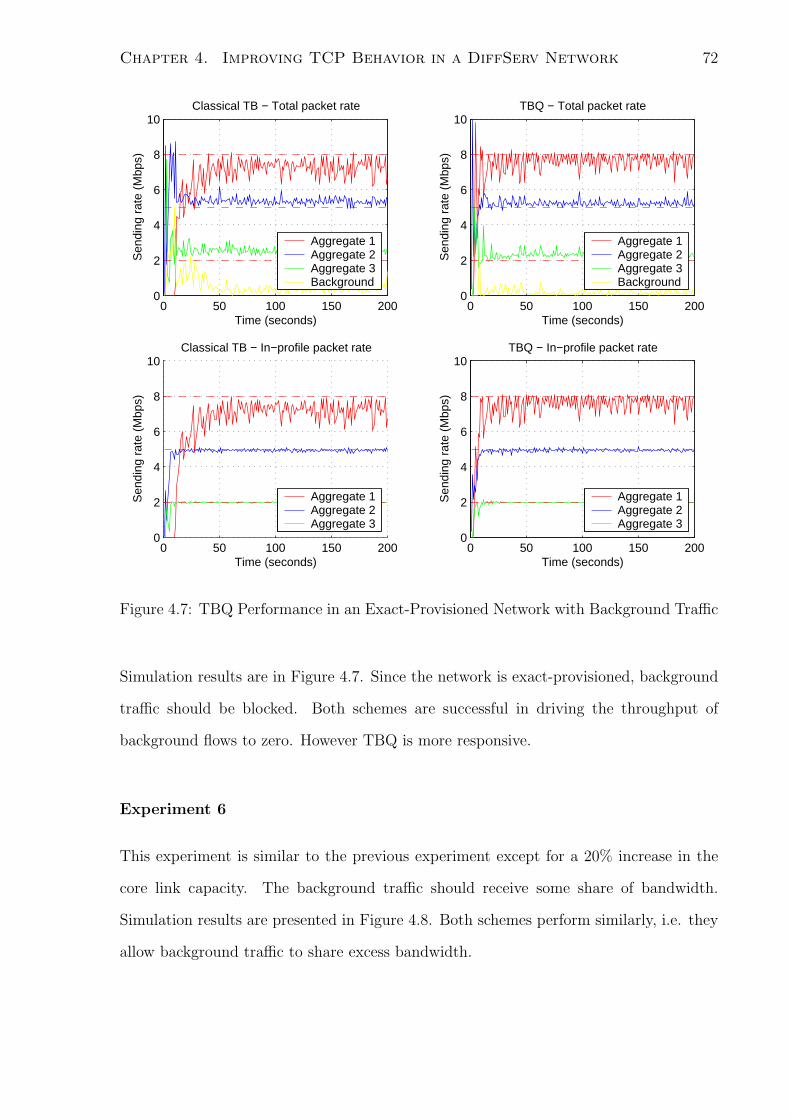
Chapter 4. Improving TCP Behavior in a DiffServ Network 72
0 50 100 150 2000
2
4
6
8
10
Time (seconds)
Sen
ding
rat
e (M
bps)
Classical TB − Total packet rate
Aggregate 1Aggregate 2Aggregate 3Background
0 50 100 150 2000
2
4
6
8
10
Time (seconds)
Sen
ding
rat
e (M
bps)
Classical TB − In−profile packet rate
Aggregate 1Aggregate 2Aggregate 3
0 50 100 150 2000
2
4
6
8
10
Time (seconds)
Sen
ding
rat
e (M
bps)
TBQ − Total packet rate
Aggregate 1Aggregate 2Aggregate 3Background
0 50 100 150 2000
2
4
6
8
10
Time (seconds)
Sen
ding
rat
e (M
bps)
TBQ − In−profile packet rate
Aggregate 1Aggregate 2Aggregate 3
Figure 4.7: TBQ Performance in an Exact-Provisioned Network with Background Traffic
Simulation results are in Figure 4.7. Since the network is exact-provisioned, background
traffic should be blocked. Both schemes are successful in driving the throughput of
background flows to zero. However TBQ is more responsive.
Experiment 6
This experiment is similar to the previous experiment except for a 20% increase in the
core link capacity. The background traffic should receive some share of bandwidth.
Simulation results are presented in Figure 4.8. Both schemes perform similarly, i.e. they
allow background traffic to share excess bandwidth.

Chapter 4. Improving TCP Behavior in a DiffServ Network 73
0 50 100 150 2000
2
4
6
8
10
Time (seconds)
Sen
ding
rat
e (M
bps)
Classical TB − Total packet rate
Aggregate 1Aggregate 2Aggregate 3Background
0 50 100 150 2000
2
4
6
8
10
Time (seconds)
Sen
ding
rat
e (M
bps)
Classical TB − In−profile packet rate
Aggregate 1Aggregate 2Aggregate 3
0 50 100 150 2000
2
4
6
8
10
Time (seconds)
Sen
ding
rat
e (M
bps)
TBQ − Total packet rate
Aggregate 1Aggregate 2Aggregate 3Background
0 50 100 150 2000
2
4
6
8
10
Time (seconds)
Sen
ding
rat
e (M
bps)
TBQ − In−profile packet rate
Aggregate 1Aggregate 2Aggregate 3
Figure 4.8: TBQ Performance in a 20% Over-Provisioned Network with Background
Traffic

Chapter 4. Improving TCP Behavior in a DiffServ Network 74
4.4 Continuous Active Rate Management
The purpose of ARM is to regulate the token bucket rate such that aggregate rates
converge to the contract rates. The following equations give a complete description of
ARM at the ith edge:
d
dtxavg,i = −kxavg,i + kxi, (4.9)
d
dtζi = max [x− xavg,i, 0] , (4.10)
ξi = kIiζi + kpi (x− xavg,i) . (4.11)
ξ denotes the token rate, x denotes the contract rate and x denotes an estimate of the
aggregate rate computed by counting the total number of sent packets in a fixed period
divided by that period. This estimate is passed through a low-pass filter with time
constant 1/k to produce a smooth rate-estimate xavg. This estimate is the input to the
proportional-integral part of ARM.
We propose a feedback structure around a token bucket similar to that of ARM, but
using a different error measure. Specifically, it compares the rate of only the in-profile
packets to the contract rate. This simple change makes ARM behave as a perfect token
bucket marker, i.e. it marks in-profile packets at precisely the contract rate. This is
an improvement over the classical token bucket marker with TCP flows. Though the
latter generates tokens at the contract rate, due to the complexities of TCP congestion
control, many tokens are wasted. Therefore the network sees in-profile packets at below
contract rates. The marking of in-profile packets at the contract rate does not disturb the
network equilibrium of an over-provisioned network. Indeed it allows TCP aggregates
to exceed contract rates in an over-provisioned network. Importantly, the information
a marked packet carries can be used for purposes other than rate regulation. We call
this mechanism Continuous Active Rate Management (CARM) due to the absence of
deactivation, in contrast to ARM. The following equations give a complete description

Chapter 4. Improving TCP Behavior in a DiffServ Network 75
of CARM at the ith edge:
d
dtxavg,i = −kxavg,i + kxi, (4.12)
d
dtζi = (x− xavg,i) , (4.13)
ξi = kIiζi + kpi (x− xavg,i) . (4.14)
where xi denotes an estimate of the aggregate in-profile packet rate computed by counting
the total number of sent in-profile packets in a fixed period divided by that period.
Similar to ARM, this estimate is passed through a low-pass filter with time constant 1/k
to produce a smooth rate-estimate xavg,i which becomes the input to the proportional-
integral part of the CARM. Because with the classical token bucket, the actual TCP
throughput is less than the token rate (due to TCP congestion control action), what is
needed is a token rate that is sufficiently higher than the contract rate so that the TCP
throughput becomes equal to the contract rate. The required higher rate may be achieved
by integral control action, equation (4.13), which produces a token rate that is a weighted
integral of the difference (error) between the contract rate and the in-profile (green) TCP
packet throughput. Adding a term that is proportional to the error, as done in equation
(4.14), yields proportional-integral (PI) [4] control which is known from control theory to
be more stable than pure integral control. PI control action is also present in (4.11) but
with an error measure that results in deactivation of any control loop where the aggregate
TCP throughput exceeds the contract rate, as seen in equation (4.10). Thus CARM may
be viewed as an adaptive version of the classical token bucket with a token rate that
automatically adjusts to the rate required to make the in-profile TCP packet throughput
equal to the contract rate. In ARM, however, the difference between the contract rate
and the sum of both in-profile and out-of-profile TCP packet throughputs is integrated,
which achieves a different outcome from the goal of the classical token bucket.
We present an analytical design of the PI controller employed in CARM. First we
model the TCP aggregate using our DiffServ controlled TCP model in chapter 3. We use

Chapter 4. Improving TCP Behavior in a DiffServ Network 76
������������������������������������������������������
������������������������������������������������������ ���������
������������������������������������������������������������������������������������������������������������������������������������������������������������������
���������������������������������������������������������������������������������������������������������������������������������������������������������������������������
W^
# RTT
Window Size
packetsOut−of−profile
2nB
vW
Lost Packets
B
Figure 4.9: The Aggregate TCP Congestion Window.
that to design the PI controller analytically.
4.4.1 Network Model
We use the same network model and notation as in section 4.3.1. We again consider the
steady state TCP behavior for
Aa >
(2na − 1)
√2na
(1pr
+ B)
+ 2na
√2naB
Ta
,
in which TCP flows fail to reach contract rates. Figure 4.9 depicts the aggregate TCP
congestion window. Once the token bucket starts marking packets out-of-profile, 1/pr of
them are transmitted before the first packet gets dropped at the congested core router.
Therefore we have
w2a
2na
= B + 1/pr,
wa =√
2na(B + 1/pr).
When a packet is lost, the congestion window of the corresponding flow is halved. There-
fore with assumption (5), the aggregate TCP congestion window is reduced by w/2na

Chapter 4. Improving TCP Behavior in a DiffServ Network 77
and we have,
wa =Wa
2na
+ wa
(1− 1
2na
)
= −Wa
2na
+
(1− 1
2na
)√2na(B + 1/pr).
If w2 > 2naB, the token bucket cannot accommodate all of the excess tokens and some
tokens are dropped. The required size of the token bucket, which prevents any token
loss, grows approximately exponential with the aggregate window size. On the other
hand the token bucket size should be chosen small to prevent any bursts of in-profile
packets that could destabilize the network. Therefore token loss is common in realistic
network scenarios. Let C denote the number of lost tokens. We have
C =w2
a
2na
−B,
=
(Wa − (2na − 1)
√2na(B + 1/pr)
)2
8n3a
−B.
The rate of in-profile (green) packets transmission, rG, averaged over a TCP congestion
window cycle is equal to
rG = Aa −naC
(w − w)T.
To simplify the calculations, we assume that 1/pr is negligible compared to B, i.e. the
network is almost exact-provisioned. Therefore we have
rG = Aa −(Wa − (2na − 1)
√2naB
)2 − 8n3aB
4naT (Wa +√
2naB),
(4.15)
Taking small deviations, the above simplifies to
δrG =
(1− 1
4ni
)δAi. (4.16)
On the other hand, if w ≥ Wa or w < Wa but (Wa−w)2
2ni< B no tokens are lost and we
have
rG = Ai.
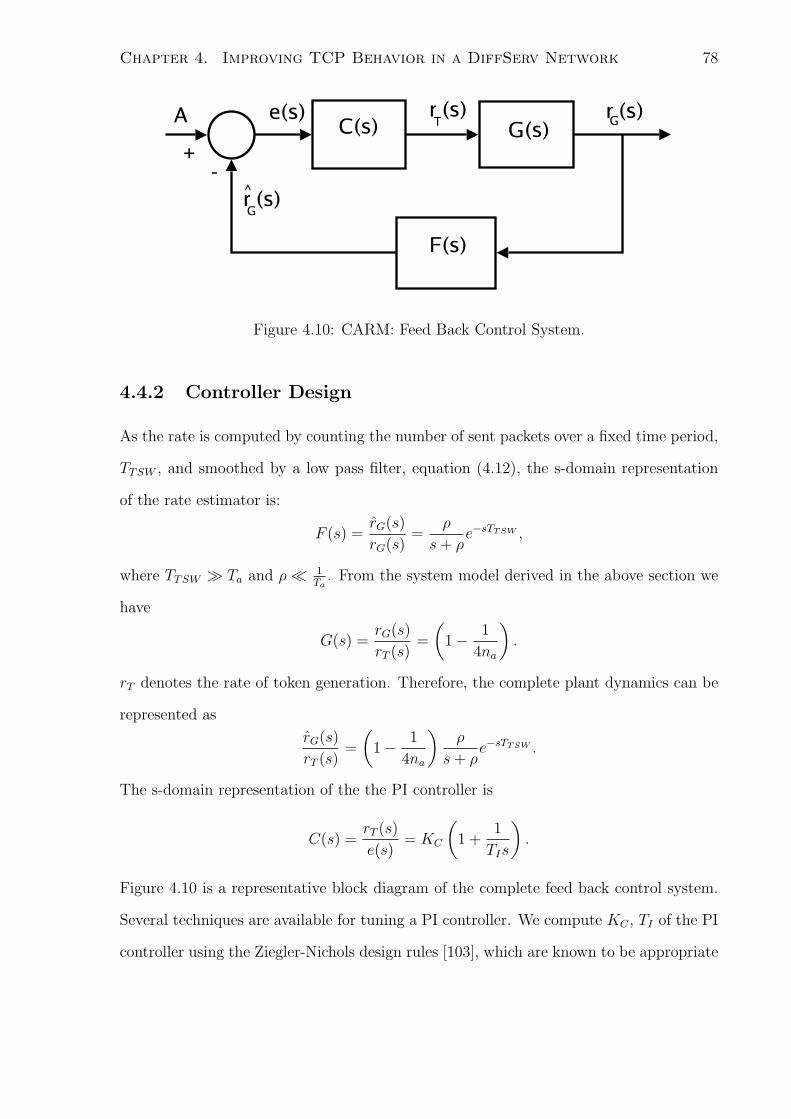
Chapter 4. Improving TCP Behavior in a DiffServ Network 78
Figure 4.10: CARM: Feed Back Control System.
4.4.2 Controller Design
As the rate is computed by counting the number of sent packets over a fixed time period,
TTSW , and smoothed by a low pass filter, equation (4.12), the s-domain representation
of the rate estimator is:
F (s) =rG(s)
rG(s)=
ρ
s + ρe−sTTSW ,
where TTSW ≫ Ta and ρ≪ 1Ta
. From the system model derived in the above section we
have
G(s) =rG(s)
rT (s)=
(1− 1
4na
).
rT denotes the rate of token generation. Therefore, the complete plant dynamics can be
represented as
rG(s)
rT (s)=
(1− 1
4na
)ρ
s + ρe−sTTSW .
The s-domain representation of the the PI controller is
C(s) =rT (s)
e(s)= KC
(1 +
1
TIs
).
Figure 4.10 is a representative block diagram of the complete feed back control system.
Several techniques are available for tuning a PI controller. We compute KC , TI of the PI
controller using the Ziegler-Nichols design rules [103], which are known to be appropriate

Chapter 4. Improving TCP Behavior in a DiffServ Network 79
Bottleneck link
N1
Ni 100 Mbps
100 Mbps
DiffServ Domain
Senders
Receivers
100 Mbps, 5 ms
32 Mbps, 20ms
Aggregate i
100 Mbps 15 ms
15 ms100 Mbps
p1
Tpi
T
Figure 4.11: CARM Performance: Simulation Network Topology
for the type of system transfer function at hand. To apply these design rules we need to
first find analytically the KC that makes the system unstable without integral control,
i.e. TI → ∞, and record the corresponding oscillation period. Clearly the oscillation
frequency is the root of the following equation in angular frequency ω,
ωTTSW + tan−1
(ω
ρ
)= π. (4.17)
Let ω = ω0 satisfy the above. For ρ≪ 1TI
, this can be approximated as
ωTTSW +π
2− ρ
ω= π.
This yields a quadratic equation in ω that has the positive solution
ω =1
TTSW
(π
4+
√π2
16+ ρTTSW
).
The Ziegler-Nichols rule then gives the appropriate integral time as
TI =1
1.2
2π
ω0
,
=2π
1.2
TTSW(π4
+√
π2
16+ ρTTSW
) . (4.18)

Chapter 4. Improving TCP Behavior in a DiffServ Network 80
To find the corresponding appropriate value of KC , we need to determine the value Ku
of KC that makes the system unstable with TI → ∞. This is obtained by setting the
magnitude of∥∥∥∥
(1− 1
4na
)Kuρe−sTTSW
1 + ρs
∥∥∥∥ = 1.
As s = jω, this yields
Ku =
√1 + (ρω0)2
ρ(1− 1
4na
)
where ω0 is given by equation (4.17). The Ziegler-Nichols rule then gives the following
value for KC :
KC = 0.45Ku,
= 0.45
√1 + (ρω)2
ρ(1− 1
4na
) . (4.19)
The above value of KC yields a system that is fast but under-damped. A less aggressive
response can be obtained by adopting a smaller value of KC . Usually na ≫ 1, so a good
approximation, that is invariant to the number of TCP flows, is obtained by replacing(1− 1
4na
)by 1. This approximation is conservative with regard to stability because it
slightly decreases the controller’s gain.
Finally, for practical implementation, we obtain the discrete-time versions of the
above estimator and controller using Tustin’s approximation, s ← 2h
z−1z+1
. where h is the
sampling interval. The token rate update becomes,
rT [k] = rT [k − 1] + ∆rT [k] (4.20)
where
∆r[k] = Kc
(1 +
h
2TI
)e[k]−Kc
(1− h
2TI
)e[k − 1],
e[k] = A− rG.
When the network is under-provisioned, the resulting rates of green packet transmission
fall below contract rates regardless of the controller. The persistent error keeps increasing

Chapter 4. Improving TCP Behavior in a DiffServ Network 81
the input to the controller and can possibly overshoot the system response when excess
bandwidth becomes available. To prevent this, we constrain the controller output. The
revised update is given in equation (4.21). This update, which is in the so-called velocity
form, prevents any integral windup due to saturated system outputs.
rT [k] = min(Amaxa , max(Amin
a , rT [k − 1] + ∆rT [k])) (4.21)
4.4.3 Simulation Studies - CARM
In this section we present ns-2 simulation studies that evaluate the performance of the
CARM token bucket. The network topology is shown in Figure 4.11. TCP aggregates
feed into a congested core with service differentiation ability. Each TCP flow is running
FTP over TCP SACK. The start times of the flows are uniformly distributed in [0,50] sec.
The RIO queue management technique [27] provides the differentiation ability at the core.
It has minthreshin = 150, maxthreshin = 300, minthreshout = 50, maxthreshout = 250,
maxprobabilityin = 0.1, and maxprobabilityout = 0.15. We used a packet size of 500
Bytes. Each edge router has a token bucket marker with a depth of 50 packets. Estimated
rates are generated by counting the number of packets in a 1 second interval. We choose
ρ = 1 rad/sec in the estimator. A sampling rate of 37.5 Hz is used in the discretization.
We have Amax = 1.25A and Amin = 0. ARM adopts the same parameters as in [25]
Experiment 1
In the first experiment we compare the performance of CARM and the token bucket
for different contract rates. We consider two TCP aggregates of which one aggregate
has no contract rate. It emulates background traffic. We vary the contract rate of the
DiffServ controlled TCP aggregate. Each aggregate consists of 30 flows. The propagation
delays of access links Tpi are all uniform in the range [15-25] ms. For each value of the
contract rate we select the core link capacity to provide 20 Mbps of excess bandwidth
for background traffic. This minimizes any change in the packet drop probability at the

Chapter 4. Improving TCP Behavior in a DiffServ Network 82
0 5 10 15 20 25 30 35 400
5
10
15
20
25
30
35
40
Contract Rate
TC
P T
hrou
ghpu
t (M
bps)
CARMClassical TB
Figure 4.12: CARM Performance for Different Values of A.
congested core as the contract rate of the DiffServ controlled TCP aggregate is varied.
Simulation results are presented in Figure 4.12. It clearly shows the marked improvement
CARM generates.
The rest of the simulation studies have three TCP aggregates with non-zero contract
rates. The propagation delays Tpi are all uniform in the ranges: Tp1 ∈ [50 − 90] msec,
Tp2 ∈ [15− 25] msec and Tp3 ∈ [0− 10] msec. Each sender consists of Ni FTP flows, all
starting uniformly in [0, 50] sec, with N1 = 20, N2 = 30 and N3 = 25. The edge routers
have contract rates equal to 8 Mbps, 2 Mbps and 5 Mbps. The parameter settings remain
fixed in all experiments.
Experiment 2
Here we compare the response in packet transmission rates for different values of α, where
Kc = αKu. Figure 4.13 plots the packet transmission rates for α=0.45, 0.2 and 0.05. We

Chapter 4. Improving TCP Behavior in a DiffServ Network 83
0 100 2000
1
2
3
4
5
6
7
8
9
10
Time (seconds)
Sen
ding
rat
e (M
bps)
Kc=0.45K
u
0 100 2000
1
2
3
4
5
6
7
8
9
10
Time (seconds)
Sen
ding
rat
e (M
bps)
Kc=0.20K
u
0 100 2000
1
2
3
4
5
6
7
8
9
10
Time (seconds)
Sen
ding
rat
e (M
bps)
Kc=0.05K
u
Figure 4.13: CARM Performance for Different Values of Kc.
have the core link capacity equal to 15 Mbps resulting in an exact-provisioned network.
A less aggressive damped response is achieved with the lowest value of α(=0.05).
Experiment 3
We consider an exact-provisioned network. Figure 4.14 plots the rates of total and in-
profile packet transmission rates seen at each edge, averaged over 1 second time intervals.
With ARM, the total rates of the aggregates slowly converge to the contract rates, but
packets are marked in-profile at a reduced rate. For CARM the total rates of packet
transmission seen in the figures are slightly over-estimated as we plot the rates of packet
Chapter 4. Improving TCP Behavior in a DiffServ Network 84
transmission seen at the edge, which includes packets that may subsequently be dropped
at the congested core. However this does not affect the rate of in-profile packet trans-
mission as these packets are not dropped in either over-provisioned or exact-provisioned
networks. This is not seen with ARM; as described above it relies on ECN marking
to signal congestion as compared to dropping packets. With CARM the rate of packet
transmission of the aggregate, that has a contract rate of 8 Mbps, exhibits more oscil-
lations for the exact-provisioned network as compared to the over-provisioned network.
Out-of-profile packets are dropped with a probability close to one in an exact-provisioned
network. Given that flows of this particular aggregate maintain very large windows, close
to 50 packets, the dropping of out-of-profile packets mostly in bursts is likely to generate
oscillations. Therefore this kind of behavior is expected.
Experiment 4
Experiment 4 compares packet transmission rates in a 20% over-provisioned network.
Figure 4.15 presents simulation results.With ARM we clearly see excess bandwidth being
accessed by just one aggregate. Moreover, aggregates mark packets at a reduced rate. In
contrast, CARM lets all aggregates share the excess bandwidth and continues marking
packets as in-profile at precisely the contract rate.
Experiment 5
Performance for an under-provisioned network is quite similar for the two token bucket
variants. Simulation results are presented in Figure 4.16.
Experiment 6
Experiment 6 investigates the effects of introducing background traffic. Short-lived TCP
sessions with random size data transfers, Pareto distributed with a shape of 1.5 and a
mean of 500 Kbytes, traverse through the congested core. The starting times of these ses-
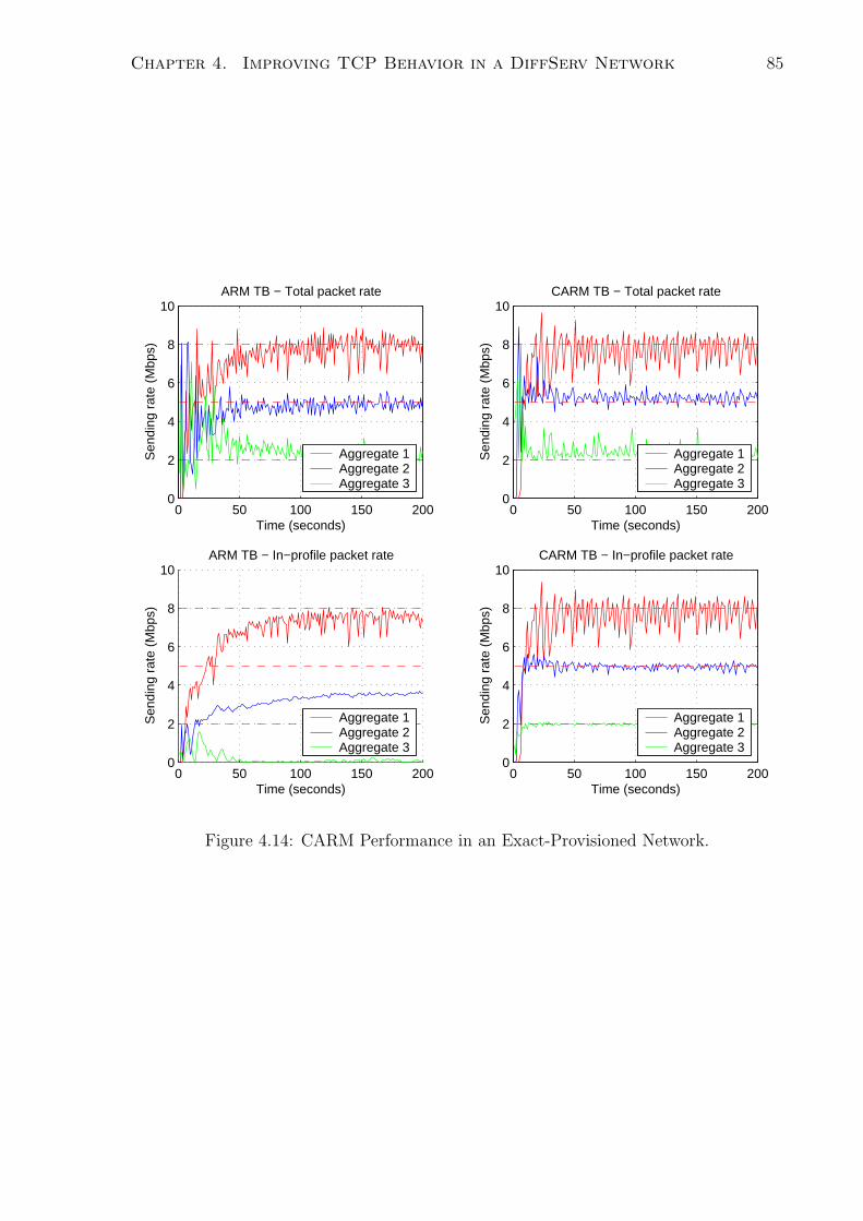
Chapter 4. Improving TCP Behavior in a DiffServ Network 85
0 50 100 150 2000
2
4
6
8
10
Time (seconds)
Sen
ding
rat
e (M
bps)
ARM TB − Total packet rate
Aggregate 1Aggregate 2Aggregate 3
0 50 100 150 2000
2
4
6
8
10
Time (seconds)
Sen
ding
rat
e (M
bps)
ARM TB − In−profile packet rate
Aggregate 1Aggregate 2Aggregate 3
0 50 100 150 2000
2
4
6
8
10
Time (seconds)
Sen
ding
rat
e (M
bps)
CARM TB − Total packet rate
Aggregate 1Aggregate 2Aggregate 3
0 50 100 150 2000
2
4
6
8
10
Time (seconds)
Sen
ding
rat
e (M
bps)
CARM TB − In−profile packet rate
Aggregate 1Aggregate 2Aggregate 3
Figure 4.14: CARM Performance in an Exact-Provisioned Network.

Chapter 4. Improving TCP Behavior in a DiffServ Network 86
0 50 100 150 2000
2
4
6
8
10
Time (seconds)
Sen
ding
rat
e (M
bps)
ARM TB − Total packet rate
Aggregate 1Aggregate 2Aggregate 3
0 50 100 150 2000
2
4
6
8
10
Time (seconds)
Sen
ding
rat
e (M
bps)
ARM TB − In−profile packet rate
Aggregate 1Aggregate 2Aggregate 3
0 50 100 150 2000
2
4
6
8
10
Time (seconds)
Sen
ding
rat
e (M
bps)
CARM TB − Total packet rate
Aggregate 1Aggregate 2Aggregate 3
0 50 100 150 2000
2
4
6
8
10
Time (seconds)
Sen
ding
rat
e (M
bps)
CARM TB − In−profile packet rate
Aggregate 1Aggregate 2Aggregate 3
Figure 4.15: CARM Performance in a 20% Over-Provisioned Network.

Chapter 4. Improving TCP Behavior in a DiffServ Network 87
0 50 100 150 2000
2
4
6
8
10
Time (seconds)
Sen
ding
rat
e (M
bps)
ARM TB − Total packet rate
Aggregate 1Aggregate 2Aggregate 3
0 50 100 150 2000
2
4
6
8
10
Time (seconds)
Sen
ding
rat
e (M
bps)
ARM TB − In−profile packet rate
Aggregate 1Aggregate 2Aggregate 3
0 50 100 150 2000
2
4
6
8
10
Time (seconds)
Sen
ding
rat
e (M
bps)
CARM TB − Total packet rate
Aggregate 1Aggregate 2Aggregate 3
0 50 100 150 2000
2
4
6
8
10
Time (seconds)
Sen
ding
rat
e (M
bps)
CARM TB − In−profile packet rate
Aggregate 1Aggregate 2Aggregate 3
Figure 4.16: CARM Performance in a 20% Under-Provisioned Network.

Chapter 4. Improving TCP Behavior in a DiffServ Network 88
0 50 100 150 2000
2
4
6
8
10
Time (seconds)
Sen
ding
rat
e (M
bps)
ARM TB − Total packet rate
Aggregate 1Aggregate 2Aggregate 3Background
0 50 100 150 2000
2
4
6
8
10
Time (seconds)
Sen
ding
rat
e (M
bps)
ARM TB − In−profile packet rate
Aggregate 1Aggregate 2Aggregate 3
0 50 100 150 2000
2
4
6
8
10
Time (seconds)
Sen
ding
rat
e (M
bps)
CARM TB − Total packet rate
Aggregate 1Aggregate 2Aggregate 3Background
0 50 100 150 2000
2
4
6
8
10
Time (seconds)
Sen
ding
rat
e (M
bps)
CARM TB − In−profile packet rate
Aggregate 1Aggregate 2Aggregate 3
Figure 4.17: CARM Performance in an Exact-Provisioned Network with Background
Traffic.
sions are exponentially distributed with a 1 second average time between arrivals. These
flows have round-trip times uniformly distributed in [70,90] msec. The first simulation
run is for an exact-provisioned network. The rate of background traffic tends to zero
as expected with both token buckets, but takes a considerably longer time with ARM.
When the network is over-provisioned as presented in Figure 4.18, background traffic
grabs a sizable portion of the excess bandwidth with ARM, whereas CARM distributes
excess bandwidth among all the aggregates. This disparity seen in excess bandwidth
distribution with ARM is a major limitation.

Chapter 4. Improving TCP Behavior in a DiffServ Network 89
0 50 100 150 2000
2
4
6
8
10
Time (seconds)
Sen
ding
rat
e (M
bps)
ARM TB − Total packet rate
Aggregate 1Aggregate 2Aggregate 3Background
0 50 100 150 2000
2
4
6
8
10
Time (seconds)
Sen
ding
rat
e (M
bps)
ARM TB − In−profile packet rate
Aggregate 1Aggregate 2Aggregate 3
0 50 100 150 2000
2
4
6
8
10
Time (seconds)
Sen
ding
rat
e (M
bps)
CARM TB − Total packet rate
Aggregate 1Aggregate 2Aggregate 3Background
0 50 100 150 2000
2
4
6
8
10
Time (seconds)
Sen
ding
rat
e (M
bps)
CARM TB − In−profile packet rate
Aggregate 1Aggregate 2Aggregate 3
Figure 4.18: CARM Performance in an Over-Provisioned Network with Background
Traffic.

Chapter 4. Improving TCP Behavior in a DiffServ Network 90
Experiment 7
We investigate network dynamics when it transitions from an under-provisioned network
to an over-provisioned network. We increase the contract rate of the second aggregate to
6 Mbps when the core link capacity remains at 15 Mbps, resulting in an under-provisioned
network. At 120 sec the second aggregate stops sending any traffic. We consider two
scenarios with the contract rate of the third aggregate equal to 5 Mbps and 7 Mbps. This
results in over-provisioned and exact-provisioned networks, respectively, beyond 120 sec.
Figure 4.19 plots the rate of in-profile and total packet transmissions averaged over 10
second intervals. The results show the ability of CARM to quickly adapt to varying
overall network subscription levels with the designed controller.

Chapter 4. Improving TCP Behavior in a DiffServ Network 91
0 50 100 150 2000
1
2
3
4
5
6
7
8
9
10
Time (seconds)
Sen
ding
rat
e (M
bps)
Total packet transmission rate
CARMClassical TB
0 50 100 150 2000
1
2
3
4
5
6
7
8
9
10
Time (seconds)
Sen
ding
rat
e (M
bps)
In−profile packet transmission rate
CARMClassical TB
0 50 100 150 2000
1
2
3
4
5
6
7
8
9
10
Time (seconds)
Sen
ding
rat
e (M
bps)
Total packet transmission rate
CARMClassical TB
0 50 100 150 2000
1
2
3
4
5
6
7
8
9
10
Time (seconds)
Sen
ding
rat
e (M
bps)
In−profile packet transmission rate
CARMClassical TB
Figure 4.19: CARM Performance under a Varying Network Load.

Chapter 5
Promoting Conformance to TCP
For the most part, the Internet still remains a best effort network. Despite the phenom-
enal growth the Internet has experienced over the years, it has been able to successfully
meet the demands of most of its users. At the heart of this success is the ability to deliver
service at times of extremely high demand. The key reasons for this are the congestion
control mechanisms of TCP. The many flavors of the additive increase multiplicative
decrease (AIMD) type of TCP algorithms at end-nodes and Tail-Drop (TD) or RED
queues at links, have been the central feature of the successful Internet Congestion Con-
trol mechanisms. Recent measurements [95] reaffirm the continued dominance of TCP as
a transport layer protocol. Therefore, most Internet traffic is thus congestion controlled.
This is remarkable given the lack of widespread deployment of any mechanisms that pro-
vide incentives for end-nodes to be TCP conformant. However, it cannot be anticipated
that this state of affairs will remain unchanged as the Internet accommodates the needs
of more and more users and applications.
The packet delivery mechanisms of TCP cannot meet the demands of a range of
applications, in particular, real-time applications. As a result, an increasing number of
applications avoid TCP, and leave the congestion control responsibility to the application
layer software. This has resulted in either limited or no congestion control mechanisms
92
Chapter 5. Promoting Conformance to TCP 93
in a large number of applications. Therefore end-nodes react to congestion differently
depending on the algorithm employed, and as a result achieve different bandwidths for
the same level of congestion. Given the fundamental heterogeneity of the Internet, and
its enormous scale, it is impossible to impose constraints directly on the end-nodes to
be TCP conformant. But routers at the edge and inside of the network can deploy
mechanisms that discourage and penalize end-nodes that are not conformant.
Algorithms such as CHOKe (CHOose and Keep for responsive flows and CHOose
and Kill for non-responsive flows) [71], RED with Preferential Dropping (RED-PD) [60],
Core-Stateless Fair Queuing (CSFQ) [91] provide such mechanisms. But as we detail
later they inherently have major limitations. We propose a mechanism that is similar in
computational complexity to CHOKE and RED-PD but is fairer and effective.
The rest of the chapter is structured as follows. Next we highlight our contributions.
Section 5.2 reviews related work. The proposed algorithm is presented in section 5.3
followed by simulation studies in section 5.4.
5.1 Our Contributions
We make the following contributions.
• We identify limitations in current algorithms designed to protect TCP flows from
congestion non-responsive flows. We show that the use of buffer occupancy as a
means of detecting misbehaving flows as done in [71] can limit TCP throughput.
On the other hand the use of packet drop history [60] does not form an accurate
measure of bandwidth share when packets are of different sizes.
• We propose an algorithm that accurately estimates bandwidth share of flows and
incorporates mechanisms that encourage conformance to the throughput of an ide-
alized TCP flow.

Chapter 5. Promoting Conformance to TCP 94
5.2 Related Work
Best effort networks deploy various techniques to improve efficiency and fairness of packet
delivery. Predominantly this includes AQM and Packet Scheduling algorithms. AQMs
such as RED [38], REM [5] and others [56, 96, 70, 47, 68, 58, 12] have improved perfor-
mance over traditional TailDrop queues. AQM help increase link utilization but lacks any
per-flow bandwidth allocation mechanisms. On the other hand packet Scheduling algo-
rithms such as Weighted Round Robin (WRR), Deficit-Weighted Round Robin (DWRR)
[87], Weighted Fair Queueing (WFQ) [72, 73], Self Clocked Fair Queueing (SFQ) [30, 40],
Worst Case Fair Weighted Fair Queueing (W2FQ) [15], Worst Case Fair Weighted Fair
Queueing + (W2FQ+) [16], Start-time Fair Queueing [41], Frame-based Fair Queueing
[90] and Starting Potential-based Fair Queueing [90] provide fine control of bandwidth
allocation.
Queue management algorithms estimate congestion and feed that information back
to end-nodes either through packet dropping or ECN. They were designed under the
assumption that end nodes are cooperative, reacting to congestion by decreasing their
sending rates. Hence they don’t have mechanisms to avoid non-responsive flows from
grabbing an unfair share of the bandwidth. These flows simply increase congestion at the
link and in turn the congestion measures of these algorithms. But being non-responsive
to congestion, their rates remain constant while conformant TCP nodes contract.
For example, consider a case in which both TCP conformant and non-responsive
flows share a link that has a queue management scheme such as RED or REM deployed.
Consider N TCP conformant end-nodes that have round trip times equal to ds and packet
size ls, and M constant rate non-responsive sources that have sending rates equal to rs
sharing a link of capacity C. We assume that this link is the only bottleneck link in its
path for all the sources and∑M
s=1 rs < C. TCP conformant nodes react to congestion
that they experience along the path by adjusting their rates. We assume that for such a
node, the congestion measure ps (packet dropping probability) relates to its sending rate
Chapter 5. Promoting Conformance to TCP 95
xs according to
xs =lsds
√3/2ps. (5.1)
This can be derived by modeling TCP’s congestion avoidance phase, ignoring other as-
pects such as slow-start and fast retransmit/fast recovery. All sources experience the
same level of congestion, and hence packet dropping probability p, due to this link being
the only bottleneck link in their path. Hence, at equilibrium, we have
N∑
s=1
lsds
√3/2p + (1− p)
M∑
s=1
rs = C. (5.2)
In summary, when TCP conformant and non-responsive flows coexist, TCP conformant
nodes are left to compete for the bandwidth share unused by the non-responsive flows.
As the rates of the non-responsive flows increase, the congestion measure keeps increasing
in tandem. As a result, the throughputs of TCP conformant nodes go down.
Scheduling algorithms, which are computationally more complex than queue man-
agement schemes, provide a fair allocation of bandwidth among competing connections.
They achieve this through flow isolation, which requires per flow state maintenance. The
high computational complexity of these algorithms limit their applicability to slow speed
interfaces.
Schemes such as CHOKe, RED-PD and CSFQ try to bridge the gap between simple
queue management schemes and computationally complex packet scheduling algorithms.
CHOKe [71] uses buffer occupancy to detect the presence of misbehaving flows and
penalize them. However buffer occupancies do not necessarily reflect the true bandwidth
share of connections. The sending rates of TCP connections with large window sizes
exhibit large variances. This shows up as a flow buffer occupancy with a commensu-
rately large variance. When global synchronization effects are no longer present, it is
possible, at a given moment, for a TCP conformant flow to have a large buffer occu-
pancy while other connections account for only a small fraction of the buffer. The bursty
nature of Internet traffic further aggravates this situation. This disproportionate buffer

Chapter 5. Promoting Conformance to TCP 96
occupancy can trigger false detections, and, as a result, conformant TCP nodes may
back-off unnecessarily. The mechanisms of TCP are such that the reaction to packet loss
is drastic, leaving TCP nodes with only a small bandwidth share under CHOKE. Using
a deterministic model of TCP, we shall illustrate this in more detail.
In CHOKe, when a packet arrives at a congested router, it draws a packet at random
from the FIFO (First In First Out) buffer and compares it with the arriving packet.
If they both belong to the same flow, then they are both dropped; else the randomly
chosen packet is left intact and the arriving packet is admitted into the buffer with a
probability that is computed exactly as in RED. In [93] it is shown that CHOKe can
bound the bandwidth share of a single non-responsive flow regardless of its arrival rate
under some conditions. However, as we explain below, CHOKe in doing so overly restricts
the bandwidth share of conformant TCP flows. When buffers are not large, it makes TCP
flows operate in a very low window regime where timeouts are frequent. We consider a
TCP conformant node that shares a one-way congested link operating CHOKe. We
make a few assumptions. We assume that the links’ propagation delays are negligible
compared with the queuing delays at the links. This allows us to assume that close to
a full window of packets resides in the link buffer. We also assume that congestion at
the link persists and as a consequence the average queue length always exceeds minth.
This implies that CHOKe is always active at the link. For simplicity we assume that the
computed probability using RED is negligible when compared to the CHOKe induced
probability. In [93], it is shown that the overall probability that packets of flow i are
dropped before they get through, either by CHOKe or congestion based dropping, is
equal to:
pi = 2hi + r − 2rhi, (5.3)
where hi is the probability of an incoming packet being dropped by CHOKe for flow i
and r is the congestion-based (RED) dropping probability. hi is equal to bi/b, where
bi is flow i’s buffer length and b is the total buffer length. With the assumptions made

Chapter 5. Promoting Conformance to TCP 97
above, the packet dropping probability equals 2hi = 2wi/b, where wi is the window size of
flow i. This is the probability that an arriving packet is matched with a randomly drawn
packet from the buffer, and the resulting loss of both packets. The effective probability of
congestion window reduction is wi/b, since multiple packet losses within a single window
will only halve the window once. This probability in turn determines the equilibrium
window size, hence we have:
wi =
√3b
2wi
. = (3b/2)1/3. (5.4)
This approximation is very conservative, since we have neglected any causes of packet
drops other than CHOKe, such as buffer overflow and RED. Moreover, in calculating the
window size we used the equation that models the congestion avoidance phase ignoring
the slow start. The above expression (5.4) for window size implies that with CHOKe
large buffers need to be maintained to avoid the window size getting too small, and
keep it away from timeouts. Since CHOKe drops two packets in a row, the minimum
window size to avoid a timeout becomes five, if a TCP Reno like implementation is used.
However, maintaining large buffers increases queuing delay. Moreover, the queuing delay
increases linearly with the buffer size, but as equation (5.4) implies, the growth of the
window is slower than linear. This has an overall effect of reducing the rate of TCP flows.
Beside this weakness, as simulation results in Section 5.4 show, CHOKe’s performance
degrades as the number of misbehaving flows increases, even though the aggregate load
remains unchanged.
A different approach is adopted in RED-PD [60]. Rather than using the buffer oc-
cupancy, it relies on the packet drop history to detect non-responsive flows and regulate
their rates. High-bandwidth flows are identified using the RED packet drop history and
flows above a configured target bandwidth are monitored. RED-PD controls the through-
put of the monitored flows by probabilistically dropping packets belonging to them at
a prefilter placed before the output queue. As we show below, the RED packet drop
history cannot itself give an unbiased estimate of the flow rate. As in equation (5.1) the

Chapter 5. Promoting Conformance to TCP 98
rate of a TCP node depends on the packet size. To mitigate this effect, many AQMs,
including RED, adopt the byte mode of operation when the packet sizes differ among
flows. In this mode of operation, a packet’s dropping probability gets scaled by the ratio
of ls/lmean, where lmean is the average packet size. Hence the rate becomes:
x =lsds
√3lmean
2pls. (5.5)
Due to the rate’s non-linear dependence on the congestion measure, effects of packet
size do not diminish even in this mode of operation. As a consequence, the flow rate
cannot be estimated by packet drop history alone. In addition to different flows with
varying packet sizes, it is also common to have different packet sizes within a single flow.
Apart from this, as [66], [46] show, RED queues are known to oscillate wildly in many
instances. A wildly oscillating queue often produces bursty packet drops, making packet
drop history an unreliable reference.
CSFQ tries to achieve a fair bandwidth allocation within a network of interconnected
edge and core routers. CSFQ is based on the interdependence between edge routers and
core routers. At ingress, edge routers mark packets with an estimate of their current
sending rate. A core router estimates a flow’s fair share and preferentially drops a packet
from a flow based on the fair share and the rate estimate carried by the packet. This
interdependence is a major limitation of CSFQ, because it is a deviation from the Internet
architecture where each node makes independent decisions on how to react to congestion.
If an edge router either maliciously or by mistake underestimates some of the rates,
then core routers will drop less packets from these flows based on the probabilistic drop
decision. CSFQ also requires an extra field in the packet headers.
We present a mechanism called Protective Queue Management (PQM) that falls be-
tween simple queue management techniques and complex scheduling algorithms, much
like CHOKe or RED-PD, but one that avoids the inherent limitations of these techniques.

Chapter 5. Promoting Conformance to TCP 99
5.3 Protective Queue Management
We build the mechanisms on top of REM, which achieves high link utilization while
maintaining low queues. We keep limited flow states thus avoiding an increase in compu-
tational complexity. The packet arrival rates of likely misbehaving flows are measured,
using the packet’s arrival time and size as done in [91]. It gives an accurate estimate of
the flow’s rate irrespective of the packet size, unlike in RED-PD. Given the congestion
measure at the link, the upper bound of a TCP conformant flow’s rate is computed.
This together with the estimated rate of the flows traversing the link are used to detect
non-responsive flows and penalize them. By using the flow’s arrival rate, we don’t rely on
buffer occupancies and hence avoid problems associated with schemes such as CHOKe.
Using equation (5.1) that models the congestion avoidance phase of TCP, the rate
of a TCP conformant end-node can be estimated using its RTT ds, packet size ls and
the congestion measure p at the link. Assuming a lower bound on the round trip time
(e.g. target queuing delay plus twice the link propagation delays) and an upper bound
on the mean packet size, we can derive an upper bound on the sending rate of a TCP
conformant end-node. It may be considered to be the fair rate of a flow traversing the link
at its current level of congestion. This knowledge allows easy detection of non-responsive
flows. All the flows that inject packets at a rate exceeding the fair share need penalizing.
Otherwise the non-responsive flows are not enjoying an unfair share of the bandwidth at
the current level of congestion and need not be penalized.
To estimate the arrival rate, we use the same exponential averaging formula as in
CSFQ. Let tki and lki be the arrival time and length of the kth packet of flow i. The
estimated rate of flow i is calculated as:
rnewi = (1− exp−T k
i /K)lkiT k
i
+ exp−T ki /K rold
i (5.6)
where T ki = tki −tk−1
i and K is a constant. If the Exponentially Weighted Moving Average
(EWMA) formula with constant weights is used instead, it artificially increases the esti-
Chapter 5. Promoting Conformance to TCP 100
mated rate when T ki becomes smaller than the average. This is a common occurrence due
to bursty sources present in the Internet. In the above formula the term (1− exp−T ki /K)
counteracts such an effect. A small K increases the system response, while a large K
filters noise and avoids system instability. However, K should be no larger than the
average flow duration.
On each packet arrival, the rate of the flow that owns the packet is computed and
compared against the fair rate. If the computed rate is more than the fair rate, the
arriving packet is discarded. Two entirely different bandwidth allocation schemes among
competing connections result, depending on whether the flow state is updated when a
packet is discarded. If it is updated, all packets of a constant rate flow that exceeds the
fair rate get discarded at the queue. We call this Protective Queue Management with a
Penalty Box (PQM-PB). This implies that a flow needs to be responsive to congestion for
it to receive a continuous non-zero share of the bandwidth. Since the level of congestion
continuously changes, so does the fair rate. Unless an end-node sending at a rate close
to fair rate, responds to congestion and reduces its rate, it may receive zero bandwidth
because the new fair rate falls below its current rate. If the flow state is not updated
when a packet is discarded, the flow’s rate approaches the fair rate. This is similar to
the behavior of traditional scheduling algorithms. The former approach looks attractive
for many reasons. It encourages end-nodes to be responsive and, on the other hand,
when a large fraction of a connection’s data is lost and never gets retransmitted, as with
multimedia applications, whatever is left may not constitute a comprehensible message.

Chapter 5. Promoting Conformance to TCP 101
Algorithm 5.3.1: Link Algorithm(ri, Tki , lki )
At the arrival of packet k belonging to flow i
if flow i is monitored
then
comment: compute flow arrival rate
T ki ← tki − tk−1
i
ri ← (1− exp−T ki /K)
lkiT k
i
+ exp−T ki /K ri
comment: penalize misbehaving flows
if (ri(1− p) > rfair)
then
drop packet
if PQM-PB
then
{update flow state
goto END
update flow state
if Buffer is full
then
drop packet
goto END
if (uniform[0, 1] < plk/lmean)
then
drop packet
include i in U
goto END
enqueue packet
:END
periodically
comment: Update dropping probability p
pl ← pl + γ(in + α(bl − btargetl )− capacity)
pl ← max(0, pl)
p← 1− φ−pl
rfair ← lmeand√
32p

Chapter 5. Promoting Conformance to TCP 102
Saved variables
ri: estimated arrival rate of flow i, tki : arrival time of
packet k of flow i, rfair: fair rate of a flow, bl: buffer level at the link, pl: link price,
p: current dropping probability, U : list of monitored flows
Fixed variables
γ: stepsize in price adjustment, α: weight of buffer in price adjustment
btargetl : target queue length, lmean: average packet size
Temporary variables
T ki : packet (k, k − 1) interarrival time of flow i, lk: length of packet k,
in: aggregate input rate estimate
Clearly we only need to compute and compare the arrival rate of congestion non-
responsive flows. Moreover, computing the arrival rate of each and every flow, including
TCP conformant short-lived flows, adds unnecessary computational overhead. A large
number of flows that traverse the link can be short lived, with only few packets in them;
hence excluding these flows from the monitoring process potentially leads to considerable
computational savings. To achieve that, we keep a list of likely misbehaving flows whose
rates need to be computed and compared against the fair rate. Several methods can
be used to construct such a list, such as examination of a flow’s packet drop history as
done in [60]. We adopt a similar method, since it requires only a small processing power
and can be run in the background. Periodically we run through the packet drop history
over a few past round-trip times, and identify flows that have lost more packets than the
congestion measure at the link would indicate, because a misbehaving flow gets a large
share of the bandwidth, it would also lose more packets than a conformant TCP end-node.
This also avoids flows from being monitored unnecessarily, if they become conformant

Chapter 5. Promoting Conformance to TCP 103
after being detected and penalized previously. Since the identification process needs to
be continuously run at the link, such a simple method is more suitable. However, the
method adopted does not affect the performance of the algorithm but only its processing
requirements. Pseudo code is presented in algorithm 5.3.1. PQM can also be used for
protecting protocols other than TCP, by using the corresponding relation of transmission
rate to packet drops for the specific protocol, in calculating the fair share.
Another application of this scheme can be rate estimation on a per-subnet or per ISP
granularity and to apply fair allocations at that level. This also means using a different
utility function [59] to that of a TCP conformant end-node, in calculating the fair rate.
As we mentioned previously, an effective identification process can reduce the state
and processing requirements of PQM. Unlike schemes such as CSFQ, not every flow
under all conditions need rate estimation, rather only the non-responsive flows present at
a congested link. When PQM starts monitoring flows, packets belonging to these flows
can be removed from the fast forwarding path of other flows and go for rate computation
and comparison, thus having a minimal effect on conformant flows.
5.4 Simulation Studies
Extensive simulation studies are conducted using a single bottleneck link shared by con-
gestion responsive TCP and congestion non-responsive constant rate UDP flows. Simu-
lations are done using ns-2.26. The link has a bandwidth equal to 64 Mbps. Throughout
the simulation run, 20 TCP flows with a round trip time equal to 30 ms share the link.
5.4.1 Experiment 1
In this simulation study we examine the effectiveness of each scheme in protecting TCP
flows under an extreme load of non-responsive flows. During 20 to 60 seconds of simula-
tion time, a UDP blast is present. It has a total accumulated rate of 96 Mbps, which is 1.5

Chapter 5. Promoting Conformance to TCP 104
0 20 40 60 80 1000
0.2
0.4
0.6
0.8
1
time (sec.)
TC
P th
roug
hput
sha
re
PQM
eight 12Mbpssix 16Mbpsfour 24Mbpstwo 48Mbps
0 20 40 60 80 1000
0.2
0.4
0.6
0.8
1
time (sec.)
TC
P th
roug
hput
sha
re
PQM−PB
eight 12Mbpssix 16Mbpsfour 24Mbpstwo 48Mbps
0 20 40 60 80 1000
0.2
0.4
0.6
0.8
1
time (sec.)
TC
P th
roug
hput
sha
re
RED
eight 12Mbpssix 16Mbpsfour 24Mbpstwo 48Mbps
0 20 40 60 80 1000
0.2
0.4
0.6
0.8
1
time (sec.)
thro
ughp
ut s
hare
CHOKE
eight 12Mbpssix 16Mbpsfour 24Mbpstwo 48Mbps
Figure 5.1: PQM Performance: Extreme Traffic Load
times the link rate. There are four simulation runs with the UDP blast consisting of two
48 Mbps, four 24 Mbps, six 16 Mbps and eight 12 Mbps UDP flows, respectively. Both
UDP and TCP flows have a packet size equal to 1000 bytes. Following the parameter
settings of [71], we have for both RED and CHOKe, minth equal to 100 packets, maxth
equal to twice that and the queue size fixed at 300 packets. For PQM, we have REM
parameter settings as used in the simulation studies presented in [5], γ = 0.005, α = 0.1,
and φ = 1.001. As for the extra parameters required in PQM we use 30 ms as the upper
limit of round-trip-time and 1000 bytes as the upper limit of packet size. Figure 5.1
presents simulation results. Among the four schemes considered, RED, CHOKe, PQM
and PQM-PB, RED has the worst performance. This is expected as RED incorporates
no techniques to protect TCP flows in the face of a UDP blast of this scale. Consis-

Chapter 5. Promoting Conformance to TCP 105
tent with the expressions derived in equation (5.2) RED’s performance is similar for all
four different types of the UDP blast, since only the aggregate UDP flow rate affects it.
However, the performance of CHOKe is not far different from that of RED: the TCP
end-nodes receive only a small fraction of the bandwidth share consistent with the anal-
ysis presented in section 5.2. In contrast, TCP end-nodes receive a significant share of
the bandwidth (0.3-0.5) when PQM is operating and an even bigger share (0.9) with
PQM-PB.
5.4.2 Experiment 2
This simulation is identical to the first, except for the presence of a less intensive UDP
blast. Here the aggregate rate is the same as the link rate. Again we do four runs of
the simulation with the UDP blast consisting of two 32 Mbps, four 16 Mbps, six 10.66
Mpbs and eight 8 Mpbs UDP flows, respectively. The simulation results are very similar
to the previous ones, except for a small increase in the TCP throughput share under all
schemes due to the less intensive UDP blast.
5.4.3 Experiment 3
We consider the effectiveness of each scheme when connections have different packet
sizes. We make the packet size of the TCP flows 400 bytes and of the UDP flows 800
bytes. Everything else is kept the same as in the first simulation. The simulation results
show that RED and CHOKe favor flows with large packets whereas PQM is unbiased, as
expected.

Chapter 5. Promoting Conformance to TCP 106
0 20 40 60 80 1000
0.2
0.4
0.6
0.8
1
time (sec.)
TC
P th
roug
hput
sha
re
PQM
eight 12Mbpssix 16Mbpsfour 24Mbpstwo 48Mbps
0 20 40 60 80 1000
0.2
0.4
0.6
0.8
1
time (sec.)
TC
P th
roug
hput
sha
re
PQM−PB
eight 12Mbpssix 16Mbpsfour 24Mbpstwo 48Mbps
0 20 40 60 80 1000
0.2
0.4
0.6
0.8
1
time (sec.)
TC
P th
roug
hput
sha
re
RED
eight 12Mbpssix 16Mbpsfour 24Mbpstwo 48Mbps
0 20 40 60 80 1000
0.2
0.4
0.6
0.8
1
time (sec.)
thro
ughp
ut s
hare
CHOKE
eight 12Mbpssix 16Mbpsfour 24Mbpstwo 48Mbps
Figure 5.2: PQM Performance: Moderate Traffic Load

Chapter 5. Promoting Conformance to TCP 107
0 20 40 60 80 1000
0.2
0.4
0.6
0.8
1
time (sec.)
TC
P th
roug
hput
sha
re
PQM
eight 12Mbpssix 16Mbpsfour 24Mbpstwo 48Mbps
0 20 40 60 80 1000
0.2
0.4
0.6
0.8
1
time (sec.)
TC
P th
roug
hput
sha
re
PQM−PB
eight 12Mbpssix 16Mbpsfour 24Mbpstwo 48Mbps
0 20 40 60 80 1000
0.2
0.4
0.6
0.8
1
time (sec.)
TC
P th
roug
hput
sha
re
RED
eight 12Mbpssix 16Mbpsfour 24Mbpstwo 48Mbps
0 20 40 60 80 1000
0.2
0.4
0.6
0.8
1
time (sec.)
thro
ughp
ut s
hare
CHOKE
eight 12Mbpssix 16Mbpsfour 24Mbpstwo 48Mbps
Figure 5.3: PQM Performance: Different Packet Sizes

Chapter 6
Conclusion
The central motivation of this thesis was to investigate and improve TCP performance
in a DiffServ network. We developed a deterministic model of a DiffServ controlled
TCP congestion window. Our model, derived from first principles, intrinsically captures
Diffserv flow aggregation. It allowed us to account for an important network parameter,
the number of flows per aggregate. Previous models, being extensions of TCP models
of a best effort network, fail to account for this important network parameter. Using
our model we derived more complete expressions of TCP steady state throughput. We
showed that the number of flows per aggregate has a profound effect on aggregate TCP
throughput. It can potentially override the effect of other network parameters such as
contract rate and round trip delay. Another important byproduct of our model is the
characterization of TCP transient behavior. We represented DiffServ controlled TCP
dynamics in a classical control system model. It allowed use of standard techniques to
analyze various mechanisms and propose improvements to algorithms as well as analysis-
backed guidelines for choosing parameters of the algorithms.
Our results reconfirm the issues TCP encounters in a DiffServ network, i.e. TCP fails
to realize contract rates under certain conditions. It cannot be expected that changing
the TCP stacks running on hundreds of millions of end nodes would be a viable solution
108

Chapter 6. Conclusion 109
to these issues. DiffServ itself needs to incorporate mechanisms that mitigate these
issues while being simple and scalable to be consistent with the DiffServ architecture.
We proposed two DiffServ markers that help TCP realize contract rates in a DiffServ
network. We proved their superior performance both analytically and experimentally.
Traditional DiffServ markers are based on token buckets. Our analysis showed that
the required token bucket depth increases exponentially with the contract rate. We
proposed augmenting the token bucket with a packet queue that holds packets arriving
at an empty token bucket. The required size of this packet queue was shown to have
a linear dependence on the contract rate. Our second marker, CARM, is an enhanced
version of ARM, a PI controller around the token bucket. It adapts the rate of token
generation, in response to the measured aggregate TCP in-profile packet transmission
rate. We presented an analytical design of the proposed PI controller, and validated the
performance of our proposed algorithms through extensive ns-2 simulation studies.
QoS networks like DiffServ are becoming increasingly popular. However, most parts
of the Internet still only provide a best effort service. Nodes rely on various QoS functions
run locally. We looked at one such QoS function, i.e. the ability to survive against flows
that are non-responsive to congestion. We highlighted deficiencies of existing mechanisms
and proposed an alternative mechanism.
It is always exciting to look ahead. We now conclude by discussing some possible
future directions of our research.
Our deterministic model of TCP can equally be applied for analysis of other congestion
reactive transport layer protocols. One obvious application is studying the performance
of new generation TCP protocols, e.g. scalable TCP, FAST TCP, in both DiffServ and
best effort networks. The model can also be extended to a three drop precedence core.
The model can be further enhanced by relaxing the assumptions we made.
TCP remains unaware of the different levels of service tags each packet receives,
and is partly responsible for its poor performance in a DiffServ network. Our proposed

Chapter 6. Conclusion 110
packet queue at the token bucket holds packets arriving at an empty token bucket. This
effectively increases the RTT of packets likely to be marked out-of-profile. This increase
in RTT can potentially be used by TCP to infer packets being marked out-of-profile
in its forwarding path. Subsequently this can be used to improve TCP’s response to
congestion.
Simulation studies done for an exact-provisioned network showed increased oscilla-
tions in packet transmission rates. This is due to the equilibrium packet drop probability
being close to the discontinuity present in the packet drop probability curve of a multiple
drop precedence core. Most networks are likely to be over-provisioned. Nevertheless this
is an area of DiffServ that requires further investigation. Though studies [88] exist for
tuning RED, the same cannot be said for multi-level RED curves used in DiffServ.
Our performance validation was confined to ns-2 simulation studies. A natural ex-
tension of this is to integrate our mechanisms into a real network testbed. This can be
accomplished using a QoS control tool like Traffic Control (TC) [49] available with the
Linux operating system.

Bibliography
[1] H. Abrahmsson, O. Hagsand, and I. Marsh. TCP over variable capacity links: A
simulation study. In Proc. of IFIP/IEEE International Workshop on Protocols for
High Speed Networks, pages 117–129, Berlin, Germany, 2002.
[2] M. Allman, V. Paxson, and W. Stevens. TCP congestion control. RFC 2581, April
1999.
[3] Eitan Altman, Konstantin Avrachenkov, and Chadi Barakat. A stochastic model
of tcp/ip with stationary random losses. IEEE/ACM Transactions on Networking,
13(2):356–369, 2005.
[4] K. J. Astrom and H. Wittenmark. Computer Controlled Systems, page 306. Prentice
Hall, 1997.
[5] S. Athuraliya, V. H. Li, S. H. Low, and Q. Yin. REM: Active queue management.
IEEE Network, 15(3):48–53, May/Jun 2001. Also in Proceedings of International
Teletraffic Congress, Salvador da Bahia, Brazil, September 2001.
[6] S. Athuraliya and H. Sirisena. An enhanced token bucket marker for DiffServ
networks. International Journal of Wireless and Optical Communications, 2(1):99–
114, June 2004.
111

Bibliography 112
[7] S. Athuraliya and H. Sirisena. An enhanced token bucket marker for Diffserv
networks. In Proc. of IEEE ICON, volume 2, pages 559–565, Singapore, November
2004.
[8] S. Athuraliya and H. Sirisena. PQM: Protective Queue Mangement of TCP flows.
In Proc. of IEEE HSNMC, pages 213–223, Toulouse, France, 2004. Springer LNCS
3079.
[9] S. Athuraliya and H. Sirisena. Active rate management in DiffServ. IEEE Com-
munications Letters, 10(6):501–503, June 2006.
[10] S. Athuraliya and H. Sirisena. Excess bandwidth distribution in DiffServ networks.
In Proc. of IEEE IPCCC, pages 119–126, Phoenix, USA, April 2006.
[11] S. Athuraliya and H. Sirisena. Controller design for TCP rate management in QoS
networks. In Proc. of IEEE BROADNETS, Raleigh, USA, September 2007.
[12] James Aweya, Michel Ouellette, and Delfin Y. Montuno. A control theoretic ap-
proach to active queue management. Computer Networks, 36(2-3):203–235, 2001.
[13] M. Baines, B. Nandy, P. Pieda, N. Seddigh, and M. Devetsikiotis. Using TCP
models to understand bandwidth assurance in a differentiated services network.
Technical report, Nortel, July 2000.
[14] C. Barakat and E. Altman. A markovian model for TCP analysis in a differentiated
services network. Telecommunication Systems, 25:129–155, 2004.
[15] J. C. R. Bennett and H. Zhang. WF2Q: Worst-case fair weighted fair queueing. In
Proc. IEEE INFOCOM, volume 1, pages 24–28, San Francisco, USA, March 1996.
[16] Jon C. R. Bennett and Hui Zhang. Hierarchical packet fair queueing algorithms.
IEEE/ACM Transactions on Networking, 5(5):675–689, 1997.

Bibliography 113
[17] S. Bhandarkar, S. Jain, and A. L. N. Reddy. LTCP: improving the performance of
TCP in highspeed networks. ACM Computer Communication Review, 36(1):41–50,
2006.
[18] D. Black, B. Carpenter, and F. Le Faucheur. Per hop behavior identification codes.
RFC 3140, June 2001.
[19] S. Blake, D. Black, M. Carlson, E. Davies, Z. Wang, and W. Weiss. An architecture
for differentiated service. RFC 2475, December 1998.
[20] R. Braden, , L. Zhang, S. Berson, S. Herzog, and S. Jamin. Resource reservation
protocol (RSVP) – version 1 functional specification. RFC 2205, September 1997.
[21] R. Braden, D. Clark, and S. Shenker. Integrated services in the internet architec-
ture: an overview. RFC 1633, June 1994.
[22] L. Brakmo and L. Peterson. TCP Vegas: End to end congestion avoidance on a
global internet. IEEE Journal on Selected Areas in Communications, 13(8):1465–
1480, 1995.
[23] Ramon Caceres, Peter B. Danzig, Sugih Jamin, and Danny J. Mitzel. Character-
istics of wide-area tcp/ip conversations. In Proc. of SIGCOMM, pages 101–112,
Zurich, Switzerland, 1991. ACM.
[24] R. Callon. Use of OSI IS-IS for routing in TCP/IP and dual environments. RFC
1195, December 1990.
[25] Y. Chait, C. V. Hollot, V. Misra, D. Towsley, H. Zhang, and Y. Cui. Throughput
differentiation using coloring at the network edge and preferential marking at the
core. IEEE/ACM Transactions on Networking, 13(4):743–754, 2005.
[26] D. Clark. The design philosophy of the darpa internet protocols. In Proc. of
SIGCOMM, pages 106–114, Stanford, United States, 1988. ACM.

Bibliography 114
[27] D. Clark and W. Fang. Explicit allocation of best-effort packet delivery service.
IEEE/ACM Transactions on Networking, 6(4):362–373, August 1998.
[28] S. Crocker, S. Carr, and V. Cerf. New host-host protocol. RFC 33, February 1973.
[29] B. Davie, A. Charny, J. C. R. Bennett, K. Benson, J. Y. Le Boudec, W. Courtney,
S. Davari, and V. Firoin. An expedited forwarding PHB. RFC 3246, March 2002.
[30] James R. Davin and Andrew T. Heybey. A simulation study of fair queueing and
policy enforcement. ACM Computer Communication Review, 20(5):23–29, 1990.
[31] S. Deering and R. Hinden. Internet Protocol, version 6 (IPv6) specification. RFC
2460, December 1998.
[32] Kevin Fall and Sally Floyd. Simulation-based comparisons of tahoe, reno and sack
tcp. ACM Computer Communication Review, 26(3):5–21, 1996.
[33] W. Fang, N. Seddigh, and B. Nandy. A time sliding window three colour marker
(TSWTCM). RFC 2859, June 2000.
[34] D. Ferrari and D. Verma. A scheme for real-time channel establishment in wide-
area networks. IEEE Journal on Selected Areas in Communications, 8(3):368–379,
1990.
[35] S. Floyd. The NewReno Modification to TCP’s Fast Recovery Algorithm. RFC
2582, 1999.
[36] S. Floyd. Highspeed TCP for large congestion windows. RFC 3649, December
2003.
[37] S. Floyd and T. Henderson. The newreno modification to TCP’s fast recovery
algorithm. RFC 2582, April 1999.

Bibliography 115
[38] S. Floyd and V. Jacobson. Random early detection gateways for congestion avoid-
ance. IEEE/ACM Transactions on Networking, 1(4):397–413, 1993.
[39] S. Floyd and V. Jacobson. TCP and explicit congestion notification. ACM Com-
puter Communication Review, 24(5):10–23, 1994.
[40] S. J. Golestani. A self-clocked fair queueing scheme for high speed applications. In
Proc. of IEEE INFOCOM, pages 636–646, Toronto, Canada, 1994.
[41] Pawan Goyal, Harrick M. Vin, and Haichen Cheng. Start-time fair queueing: a
scheduling algorithm for integrated services packet switching networks. IEEE/ACM
Transactions on Networking, 5(5):690–704, 1997.
[42] G. H. Hardy. A Course of Pure Mathematics, page 398. Cambridge University
Press, London, 1938.
[43] J. Heinanen, F. Baker, W. Weiss, and J. Wroclawski. Assured forwarding PHB.
RFC 2597, June 1999.
[44] J. Heinanen, T. Finland, and R. Guerin. A single rate three color marker. RFC
2697, September 1999.
[45] J. Heinanen, T. Finland, and R. Guerin. A two rate three color marker. RFC 2698,
September 1999.
[46] C. V. Hollot, Vishal Misra, Donald F. Towsley, and Weibo Gong. A control theoretic
analysis of RED. In Proc. of IEEE INFOCOM, pages 1510–1519, Alaska, 2001.
[47] C.V. Hollot, V. Misra, D. Towsley, and W. Gong. On designing improved controllers
for AQM routers supporting TCP flows. In Proc. of IEEE INFOCOM, volume 3,
pages 1726–1734, Alaska, 2001.

Bibliography 116
[48] H. Hsieh and R. Sivakumar. pTCP: An end-to-end transport layer protocol for
striped connections. In Proc. of IEEE ICNP, pages 24–33, Washington, DC, USA,
2002. IEEE Computer Society.
[49] B. Hubert. Linux Advanced Routing and Traffic Control HOWTO.
[50] V. Jacobson. Congestion avoidance and control. ACM Computer Communication
Review, 18(4):314–329, 1988.
[51] V. Jacobson. Modified TCP congestion avoidance algorithm. end2end-interest
mailing list, April 1990. ftp://ftp.isi.edu/end2end/end2end-interest-1990.mail.
[52] B. Kantor. BSD Rlogin. RFC 1258, September 1991.
[53] Dina Katabi, Mark Handley, and Charlie Rohrs. Congestion control for high
bandwidth-delay product networks. In Proc. of SIGCOMM, pages 89–102, Pitts-
burgh, USA, 2002. ACM.
[54] T. Kelly. Scalable TCP: Improving performance in highspeed wide area networks.
ACM Computer Communication Review, 32(2), 2003.
[55] S. Kunniyur and R. Srikant. End-to-end congestion control schemes: Utility func-
tions, random losses and ECN marks. In Proc. of IEEE INFOCOM, pages 1323–
1332, Tel-Aviv, 2000.
[56] S. Kunniyur and R. Srikant. An adaptive virtual queue (AVQ) algorithm for active
queue management. IEEE/ACM Transactions on Networking, 12(2):286–299, 2004.
[57] T. Lakshman and U. Madhow. The performance of TCP/IP for networks with
high bandwidth-delay products and random loss. IEEE/ACM Transactions on
Networking, 5(3):336–350, July 1997.

Bibliography 117
[58] A. Lakshmikantha, C. L. Beck, and R. Srikant. Robustness of real and virtual
queue-based active queue management schemes. IEEE/ACM Transactions on Net-
working, 13(1):81–93, 2005.
[59] S. H. Low. A duality model of TCP and queue management algorithms.
IEEE/ACM Transactions on Networking, 11(4):525–536, August 2003.
[60] R. Mahajan, S. M. Bellovin, S. Floyd, J. Ioannidis, V. Paxson, and S. Shenker.
Controlling high bandwidth aggregates in the network. ACM Computer Commu-
nication Review, 32(3):62–73, 2002.
[61] S. Mascolo. Congestion control in high-speed communication networks using the
Smith principle. Automatica, 35(12):1921–1935, December 1999.
[62] M. Mathis, J. Mahdavi, S. Floyd, and A. Romanow. TCP selective acknowledge-
ment options. RFC 2018, April 1996.
[63] M. Mathis, J. Semke, and J. Mahdavi. The macroscopic behavior of the TCP con-
gestion avoidance algorithm. ACM Computer Communication Review, 27(3):67–82,
1997.
[64] Archan Misra and Teunis J. Ott. The window distribution of idealized TCP con-
gestion avoidance with variable packet loss. In Proc. of IEEE INFOCOM, pages
1564–1572, New York, 1999.
[65] V. Misra, W. Gong, and D. Towsley. Stochastic differential equation modeling and
analysis of TCP-windowsize behavior. In Proc. of PERFORMANCE, 1999.
[66] Vishal Misra, Wei-Bo Gong, and Donald F. Towsley. Fluid-based analysis of a
network of AQM routers supporting TCP flows with an application to RED. In
Proc. of ACM SIGCOMM, pages 151–160, Stockholm, Sweden, 2000.
[67] J. Moy. OSPF version 2. RFC 2328, April 1998.

Bibliography 118
[68] T. J. Ott, T. V. Lakshman, and L. H. Wong. Sred: Stabilized red. In Proc. of
IEEE INFOCOM, volume 3, pages 1346–1355, New York, 1999.
[69] J. Padhye, V. Firoiu, D. Towsley, and J. Krusoe. Modeling TCP throughput: A
simple model and its empirical validation. In ACM SIGCOMM, pages 303–314,
Vancouver, 1998.
[70] F. Paganini, Z. Wang, S.H. Low, and J.C. Doyle. A new TCP/AQM for stable
operation in fast networks. In Proc. of IEEE INFOCOM, volume 1, pages 96–105,
San Francisco, USA, 2003.
[71] R. Pan, B. Prabhakar, and K. Psounis. CHOKE, a stateless active queue man-
agement scheme for approximating fair bandwidth allocation. In Proc. of IEEE
INFOCOM, pages 942–951, Tel-Aviv, 2000.
[72] Abhay K. Parekh and Robert G. Gallager. A generalized processor sharing
approach to flow control in integrated services networks: the single-node case.
IEEE/ACM Transactions on Networking, 1(3):344–357, 1993.
[73] Abhay K. Parekh and Robert G. Gallagher. A generalized processor sharing ap-
proach to flow control in integrated services networks: the multiple node case.
IEEE/ACM Transactions on Networking, 2(2):137–150, 1994.
[74] K. Poduri and K. Nichols. Simulation studies of increased initial TCP window size.
RFC 2415, September 1998.
[75] J. Postel. Internet Protocol. RFC 791, September 1981.
[76] J. Postel. Transmission Control Protocol. RFC 793, September 1981.
[77] J. Postel. Simple mail transfer protocol. RFC 821, August 1982.
[78] J. Postel. Summary of computer mail services meeting held at bbn on 10 january
1979. RFC 808, March 1982.

Bibliography 119
[79] J. Postel and J. Reynolds. Telnet protocol specification. RFC 854, May 1983.
[80] J. Postel and J. Reynolds. File Transfer Protocol. RFC 959, October 1985.
[81] K. Ramakrishnan, S. Floyd, and D. Black. The addition of explicit congestion
notification (ECN) to IP. RFC 3168, September 2001.
[82] Y. Rekhter and T. Li. A border gateway protocol 4. RFC 1771, March 1995.
[83] D.J.Leith R.N.Shorten. H-TCP: Tcp for high-speed and long-distance networks.
In Proc. of PFLDnet, 2004.
[84] E. Rosen, A. Viswanathan, and R. Callon. Multi-Protocol Label Switching archi-
tecture. RFC 3031, January 2001.
[85] Sambit Sahu, Philippe Nain, Christophe Diot, Victor Firoiu, Don Towsley, and
Don Iowsley. On achievable service differentiation with token bucket marking for
TCP. In Proc. of SIGMETRICS, pages 23–33, Santa Clara, United States, 2000.
ACM Press.
[86] S. Shenker, C. Partridge, and R. Guerin. Specification of guaranteed quality of
service. RFC 2212, September 1997.
[87] M. Shreedhar and George Varghese. Efficient fair queueing using deficit round
robin. ACM Computer Communication Review, 25(4):231–242, 1995.
[88] H. Sirisena, Aun Haider, and Krzysztof Pawlikowski. Auto-tuning RED for accurate
queue control. In Proc. of IEEE GLOBECOM, volume 2, pages 2010–2015, Taipei,
November 2002.
[89] W. R. Stevens. TCP/IP Illustrated, Volume 1: The Protocols. Addison-Wesley,
1994.

Bibliography 120
[90] Dimitrios Stiliadis and Anujan Varma. Efficient fair queueing algorithms for packet-
switched networks. IEEE/ACM Transactions on Networking, 6(2):175–185, 1998.
[91] I. Stoica, S. Shenker, and H. Zhang. Core-Stateless Fair Queueing: Achieving
approximately fair bandwidth allocations in high speed networks. In ACM SIG-
COMM, pages 118–130, Vancouver, 1998.
[92] H. Su and M. Atiquzzaman. Comprehensive performance model of differentiated
service with token bucket marker. Communications, IEE Proceedings, 150:347–353,
2003.
[93] A. Tang, J. Wang, and S. H. Low. Understanding CHOKe. In Proc. of IEEE
INFOCOM, volume 1, pages 114–124, San Francisco, Mar/Apr 2003.
[94] S. Tartarelli and A. Banchs. Random Early Marking: improving TCP performance
in DiffServ assured forwarding. In Proc. of IEEE ICC, pages 970– 975, New York,
2002.
[95] K. Thompson, G. Miller, and R. Wilder. Wide-area internet traffic patterns and
characteristics. IEEE Network, 11(6):10–23, Nov/Dec 1997.
[96] C. Wang, B. Li, Y.T. Hou, K. Sohraby, and Y. Lin. LRED: a robust active queue
management scheme based on packet loss rate. In Proc. of IEEE INFOCOM,
volume 1, pages 7–11, 2004.
[97] D. X. Wei, C. Jin, S. H. Low, and S. Hegde. FAST TCP: motivation, architecture,
algorithms, performance. IEEE/ACM Transactions on Networking, 14(6):1246–
1259, December 2006.
[98] G. R. Wright and W. R. Stevens. TCP/IP Illustrated, Volume 2: The Implemen-
tation. Addison-Wesley, 1995.

Bibliography 121
[99] J. Wroclawski. Specification of the controlled-load network element service. RFC
2211, September 1997.
[100] L. Xu, K. Harfoush, and I. Rhee. Binary increase congestion control for fast long-
distance networks. In Proc. of IEEE INFOCOM, volume 4, pages 2514–2524, Hong
Kong, 2004.
[101] I. Yeom and A. L. N. Reddy. Realizing throughput guarantees in a differentiated
services network. In Proc. of ICMCS, page 372, Washington, DC, USA, 1999. IEEE
Computer Society.
[102] I. Yeom and A. L. Narasimha Reddy. Modeling TCP behavior in a differentiated
services network. IEEE/ACM Transactions on Networking, 9(1):31–46, 2001.
[103] J. G. Ziegler and N. B. Nichols. Optimum settings for automatic controllers. Trans-
actions of the ASME, 64:759–768, 1942.