tcox . installation instructions field installed staged electric heat for lennox elite 10"...
TRANSCRIPT

zEA,tcOx ._;_,1997 Lennox Industries {nc,
Dallas, Texas, USA
/
II
The EvenHeater'" ECB29EH electric heat sections pro-vide field installed staged electric heat for Lennox Elite 10"CB29M, Elite 12" CB30M, Elite 12" CB30U, and Power-Mate" CB31MV blower coil units.
In heat pump applications, the electric heat is staged toprovide supplemental heat to meet desired comfort levels.When the electric heat section is used in applications thatdo not have a heat pump, the elements are staged to limitheat so that it meets heating demands only.
Adjust element staging by changing the location of thesupply air temperature-selection jumper on the ECH1control board.
ECB29EH heat sections are available in single-phase9kW, 12.5 kW, 15 kW, and 20kW sizes. Heaters areequipped with circuit breakers. Refer to the engineeringhandbook for specific heat section applications.
INSTALLATIONINSTRUCTIONS
EVENHEATER TM ELECTRICHEAT SECTIONS
ELECTRIC HEAT SECTIONS F_-_ Technical503,675M _'LLL. Publications5/99Supersedes 7/97 Lithe U.S.A.
ECB29EH Electric Heat Sections ................. 1Shipping & Packing List ......................... 1General Information ............................ 1Heat Section Installation ........................ 2Circuit Breaker Installation ....................... 2Thermistor Installation .......................... 4EHCl Control Board Installation .................. 4Electrical Connections .......................... 5Blower Speed Connections ...................... 6Discharge Air Temperature Adjustment ............ 6Unit Start-Up .................................. 6Troubleshooting ................................ 6Wiring Diagrams ............................... 7
RETAIN THESE INSTRUCTIONSFOR FUTURE REFERENCE
These instructions are intended as a general guide and donot supersede local codes in any way. Consult authorities
having jurisdiction before installation. Read these instruc-tions thoroughly before installing the heater section.
The electric heat section and all other equipment used inHVAC systems must only be installed by qualified installersor technicians. You must follow federal, state, and localcodes while installing this or any other HVAC equipment.
,& WARNING
Package 1 of 1 contains:
1 - Assembled electric heat section
1 - Bag assembly containing the following:10-Screws; 1-Wiring diagram; 2-Wire nuts
1 - EHC1 control board assembly
1 - Supply air plenum thermistor2 - Adhesive-backed foam seals
1 - Control bracket
Inspect the heater section for shipping damage. If you findany damage, immediately contact the last carrier.
Be sure to disconnect all power to unit while installing andservicing the equipment. Use proper tools and protectiveequipment during installation and service.
Installation of Lennox blower sections with or without op-tional electric heat must conform with standards in the Na-
tional Fire Protection Association (NFPA) "Standard for
Installation of Air Conditioning and Ventilation SystemsNFPA No. 90A," and "Standard for Installation of Resident
Type Warm Air Heating and Air Conditioning System, No.90B," manufacturer's installation instructions, and localmunicipal building codes.
Page 1

Before installing the unit, check information on unit rat-ing plate to ensure unit meets job specification, properelectrical power is available and that proper duct clear-ances are maintained.
WARNING
NOTE-It is easier to install the ECB29EH heat section in
the blower coil unit before the unff is set and the plenum isattached.
1 - Shut off all power to blower coil unit, More thanone disconnect may be required.
2 - Remove blower section access panel.
3 - Remove electric heat knockout in blower coil vesti-bule panel for the appropriate size of heater used.Remove extended width knockout to allow forinstallation of 20kW heater. See figure 1.
BLOWER COIL KNOCKOUTS
KNOCKOUT FOR:
(_ CB29M-21/26,-31 _)1_ CB30M-21/26 _)
""\ Holes In knockout allow• room for dtagonal cutters
used to cut through
sheet metal.
JJ CB29M-41, -46, -51, -55
CB31MV-41, -51, -65
II II
a 20kW el_rlC heater.
FIGURE 1
4- Slide electric heat section into blower section. Becareful that heating elements do not rub againstsheet metal opening when sliding into blower sec-tion. Hole(s) on each side of the heater line up withholes in the blower coil control box. Secure elec-tric heater into place with screws provided in bagassembly.
1 - Install circuit breaker on blower deck flange. Useprovided screws to secure. See figure 2.
ELECTRIC HEAT SECTIONWITH CIRCUIT BREAKERS
In downflow applications, circuit breakersmust be rotated 180 ° to the UP position.
BLOWER DECK\/ CIRCUIT -\ •
A v BREAKERS
CIRCUIT ._-"__._-_
BRE_KE__R ,,,_- .--_._J IBRACKET _r
CIRCUIT BREAKERMOUNTING SCREW
(Remove screw and slide breakers offmounting rail. Rotate breakers 180 ° and
slide bark on rail. Secure with screw.)
NOTE - When applied in the downflow position, the cir.cuit breakers must be rotated to the UP position. Seefigure 2 and follow the procedure below.
a - Disconnect power to the unit if present.b - Remove screw and slide breakers off mount-
ing rail.
NOTE- Wire tie closest to the circuit breaker mayneed to be removed to allow for rotation.
c - Rotate circuit breaker 180 °.d - Slide circuit breaker back on rail and secure in
place with previously removed screw.
2- Blower coil access panels are factory suppliedwith a patch plate over the circuit breaker open-ing. Remove the circuit breaker patch plate fromthe blower access panel. See figure 3
3 - Replace the unit blower access door.
4 - Choose the appropriately sized adhesive-backedcircuit breaker seal and remove any perforatedsections (if needed). Apply the seal to the outsideof the blower access panel so that the seal is snugaround the circuit breakers.
5 - Break the patch plate for the specific size of elec-tric heat unit/blower coil unit being installed. Dis-card unused piece of patch plate. Refer to figure4 for CB29M-21/26, CB29M-31, CB30M-21/26,CB30U-21/26 units; refer to figure 5 for all otherblower coil units.
6 - Secure the patch plate on the blower access door.
Page 2

CIRCUIT BREAKER SEALAND PATCH PLATE INSTALLATION
CIRCUITBREAKERS
CIRCUITBREAKER SEAL
\PATCH PLATE BLOWER DECK
CIRCUITBREAKERBRACKET
! DISCARD
PATCH L..._.__j
BREAK AT THIS POINT
FIGURE 3
PATCH PLATE(Shipped installed on CB unit)
I I I /S °;o n/
f I i /
Patch plateshown with longest section onright side, Patch plate may be
factory installed with long sec-tion on left side.
CIRCUIT BREAKER SEAL(Shipped with electrical heat
and Field installed)
Dotted lines'are perforations
CIRCUIT BREAKER HEATERAND PATCH PLATE CONFIGURATION
CB29M-21126, CB29M-31, CB30M-21/26_26
ECB29EH-gCB
SideOf
Unit
ECB29EH-12.5CBECB29EH-15CB
SideOf
Unit
ROTATE 180 ° andinstall over opening
I I
I LongSection
Break at this point
FIGURE 4
ROTATE 180 ° andinstall over opening
r-.-3-_- _:_ ....I I II I I LongI { I Section
L _L_I_ _ ..........
Break at this point
Page 3

CIRCUIT BREAKER HEATERAND PATCH PLATE CONFIGURATION
CB29M-41, CB29M-46, CB29M-51, CB29M-65 ANDCB30M-31, CB30M-41, CB30M-46, CB30M-51 CB30M-65 AND
CB31M-41, CB31M-51, CB31M-65 ANDC830U-31, CB30U-41/46, CB30U-51/65
PATCH PLATE(Shipped installed on CB unit)
Patch plateshown with longest section on right
side, Patch plate may be factoryinstalled with long section on Left side.
CIRCUIT BREAKER SEAL(Shipped with electrical heat
and Field installed)
Dotted linesare perforations
ECB29EH-gCB
SideOf
ROTATE 180 ° andinstall over o
f-- -_-=qI II [I 1L c=/
Break at this point
ECB31EH-gCB, ECB29EH-12.SCBECB29EH-15CB, ECB29EH-20CB
SideOf
install over opening
-1I I
I I iL_,J _J
I DISCARD ]_Break at this point
FIGURE 5
See figure 6 for thermistor installation.
1 - Drill a 5/8" hole in supply air plenum front. Locatehole 10" (254mm) above blower coil cabinet top,centered side to side.
2- Insert thermistor probe into the hole and securewith two provided #8-18 self-drill self-tap screws.
3 - Adjust the probe depth as shown in figure 6.
4- Before installing the EHC1 control board assem-bly, run the two thermistor leads through low volt-age cabinet knockout opening and connect to"DAT" terminals on control board.
Refer to figure 7 for control board assembly installation.
1- Assemble ECH1 control board with mountingbracket. See figure 7 for orientation.
2 - On CB29M, CB3OM & CB3OU units -Align EHC1 control board assembly bracket holeswith existing blower deck flange holes (located onthe right side of the flange) and secure controlboard assembly with two provided screws.
3 - On CB31MV units -Use the two existing screws that secure the vari-able speed motor control board bracket to blowerdeck flange to install the EHC1 control board as-sembly to blower deck flange.
THERMISTOR INSTALLATIONTHERMISTOR
(center side to side) _
Probe* 5-9/16 L1012541 depth 11411 p"
SUPPLYAIR PLENUM
UNIT SUPPLYAIR OPENING
OPTIONALELECTRIC
HEAT(Reid
Installed)
* Thermistor probe depth is measured from frontof blower coil unit supply air opening - not supplyair plenum front (unless they are identical).
RGURE 6
Page 4

EHC1CONTROLBOARDINSTALLATION
f f
II
I, Blower
Existing blower deckflange holesI
_\ EHCl Control board assembly_. _/ \ Thermostat terminal strip this side
FIGURE 7
EHCl CONTROL BOARD WITH WIRE HARNESSThermistor terminals Thermostat
.... .terminal strip/ /nermostat
terminals _
DAT W1
; ..........J°* 00.wi o,_G 2G eo............./O 130oEG
100 DEG85 DEG
Heater indicator Diagnosticlights indicator
Temperature lightsselection jumper
Wire harness jack Wire harness p
FIGURE 8
A WARNING
NOTE-Refer to nameplate on blower coil unit for mini-mum circuit ampacity and maximum overcurrent protec-tion size.The blower coil units are provided with openings for usewith 1-1/2 inch trade size (1-31/32 inch diameter) con-duit. A conduit reducer washer has been provided foruse if installing smaller conduit.Refer to figure 9 for typical condensing unit applicationand figure 10 for typical heat pump application with ablower coil unit and an electric heat section.
Refer to figure 11 and 12 for typical system diagram forthe CB29M/CB30M/CB30U unit with installed electricheat sections and figure 13 and 14 for typical systemdiagram for the CB31MV unit with installed electricheat section,
Make wiring connections as follows -Refer to figures 8 and 9 for condensing unit applica-tion and to figures 8 and 10 for heat pump applica-tion.
1 - Connect field power supply wiring to circuit break-er(s).
2 - Connect heater section wire harness plug "P2" toEHC1 control board left side wire harness jack"J166."
3- Remove interface harness from blower coil sec-tion. Connect blower coil section wire harness jack"J2" to EHC1 control board right side wire harnessplug "P166."
4 - Use provided wire nut to connect stripped yel-low wire from "Y" terminal of EHC1 controlboard to wire from "Y1" terminal of indoor ther-mostat inside blower coil cabinet.
5 - In heat pump applications only -Use provided wire nut to connect strippedorange wire from "O" terminal of EHC1 controlboard to wire from "0" terminal of indoor ther-mostat inside control box. Remove the factoryinstalled jumper between EHC1 control boardterminals "O" and "R."
6- Disconnect existing red wire from terminal "R" ofTB1 terminal block. Connect this wire to tab of tab/receptacle combination of red wire from terminal"R" of EHC1 control board. Then connect thiswire-assembly to terminal "R" of TB1 terminal block.
7 - In applications where outdoor thermostat is usedonly -Remove jumper between "W2" and "R" of TB1 ter-minal block and connect outdoor thermostat leadsto "W2" and "'R."
Page 5

When using the ECB29EH heat section with the CB29M,CB30M, CB30U or CB31MV series blower coil units, the
blower speed must be adjusted according to the size ofelectric heat and blower coil unit. The minimum blow-
er setting for each blower size, with any heat sectionsin any application is HIGH. See specific blower coilinstallation instructions for blower speed adjustmentprocedure and location.
The EHC1 control board can be adjusted to providefour different discharge air temperatures: 85°F(29.5°C), 100°F (37.8°C), 115°F (46.1°C) and 130°F
(54.4°C). To adjust the factory setting of 85°F (29.5°C),move the temperature selection jumper on the EHC1control board to the desired setting (see figure 8).The EHC1 control board uses the discharge air temper-atu re value provided by the thermistor to maintain theselected discharge air temperature by staging on therequired number of heating elements.
When higher discharge air temperatures are requiredfor comfort or to satisfy the heating load, change thetemperature selection jumper on the EHC1 controlboard to a higher setting. In heat pump applications,when the heat pump is on and a "Wl" demand is pres-
ent from the indoor thermostat, the control board tem-
perature setting will automatically increase to the nexthigher setting. Once the "Wl" demand is satisfied orremoved, the control board temperature setting willautomatically return to the jumper setting.
1 - Replace blower compartment access cover.
2 - Restore power to unit.
3 - Set thermostat heat anticipator to 0.4 amps.
4 - Set thermostat above room temperature.
5 - Verify that element staging and supply air tempera-tures are correct for the given application. If unex-pected results are obtained, check heat pump andheat section for normal operation. A table show-ing diagnostic codes for the EHC1 control board isgiven in the troubleshooting section of theseinstructions.
6 - Set thermostat to desired setting.
7-Affix wiring diagram sticker to blower scroll,aligned with existing CB unit wiring diagramsticker.
Refer to table 1 for EHC1 control board diagnosticcodes.
See figure 8 for location of diagnostic and operationindicator LEDs.
Page 6

TABLE1EHC1 CONTROLBOARDDIAGNOSTICCODES
BOARD DIAGNOSTIC PATTERNS
DIAG 1 _ Flashing SlowDIAG 2 • On
DIAG 1 • On
DIAG 2 _ Flashing Slow
DIAG 1 _1_ Fleshing Alternately fast
DIAG 2 -_ Flashing Alternately Slow
DIAG 1 1"_ Fleshing Alternately Slow
DIAG 2 1_ _ Fleshing Alternately Fast
DIAG 1 • Continuously On
DIAG 2 O Continuously Off
DIAG 1 O Continuously Off
DIAG 2 • Continuously On
DIAG 1 • Continuously On
DIAG 2 • Continuously On
MODE INDICATION
Normal Operation
Shorted Thermistor*
REMEDY
None. Slow fleshing LED signifies normsl operation.
General Failure
General Failure
General Failure
Check thermistor for short circuit
Open Thermistor* Check thermistor for open circuit.
Jumper Error Resistor fault on board, Board must be replaced.
No Jumper** No temperature-seloctlon jumper installed. Install jumper
Component fault on board. Board must be replaced.
Component fault on board. Board must be replaced.
Component fault on board. Board must be replaced,
Component fault on board. Board must be replaced.DIAG 1 O Continuously Off General FailureDIAG 2 O Continuously Off
* This mode of operation is indicated b_ elements staging on every 4 minutes until "WI" demand is satisfied.** Last setting retained by board if jumper removed while unit operating; if no jumper present on
power-up,the default setting of 85°F is used by the board.
LI208-240/60/I
K3 INDOORCIRCUIT BREAKERS BLOWER RELAY
HEATING ELEMENTS
| ((_Z'Z_x_.-._'x/'''''_z_HEATRELAYs []' 'lJi-- ............_-- "L__r
EHC1 CONTROL BOARD IO O O O O O
\ L LI_JFJ \ I _t j
I \ ................. td
Avlg
COOLING APPLICATION WITH ELECTRIC HEATNOTE-USE COPPERC0_CTORS ONLY,
REFER TO UNIT RATING PLATEFOR MINIMUM CIRCUIT AMPACITYAND MAXIMUM OVERCURRENTPROTECTION SIZE
LINE VOLTAGE FIELD INSTALLED
CLASS 2 VOLTAGE FIELD INSTALLED
NEC/CEC
L_ TO EXTERNAL LOAD 24VACAT .50 AMP MAXIMUM
,,t,,THERMOSTAT HEAT ANTICIPATION
SETTING .4 AMP (ELECTRIC HEAT)
FACTORY INSTALLED JUMPER
SEE UNIT FOR QUANTITY OF ELEMENTSOR HEAT RELAYS
WHEN OUTDOOR THERMOSTAT IS USED,CONNECT LEADS TO TERMINALS"R" AND "W2 _AND REMOVE JUMPER BE-TWEEN TERMINALS "R' AND "W2,"
FIGURE 9
Page 7

L2 LI
r1,o,,o,,oI C,RC,.,,rB,'=.'.,,:ERS,_L_ -- ,E,,,"r,N,_EW.,EN',',,
.EZ
,_k--
K3 INDOOR
BLOWER RELAY
EHCICONTROLBOARD
II I II II
J IJ
K22BI ItEAT
II!III
J
HEAT PUMP APPLICATIONWITH ELECTRIC HEATLINE VOLTAGE FIELD INSTALLED
CLASS 2 VOLTAGE FIELD INSTALLEDNEC/CEC
THERMOSTAT HEAT ANTICIPATIONSETTING 0.4 AMP ELECTRIC HEAT
FACTORY INSTALLED JUMPERS
WHEN OUTDOOR THERMOSTAT IS USED,CONNECT LEADS TO TERMINALS"R" AND "W2" AND REMOVE JUMPER BE-TWEEN TERMINALS "R' AND "W2,"
EMERGENCY HEAT RELAY (USED ONLY IF OUT-DOOR T'STAT IS USED) FIELD PROVIDEDAND INSTALLED NEAR INDOOR UNIT. 24VAC5VA MAX NEC/CEC CLASS 2
= R
$23m
USING SERVICE UGHT OPTION ($54) WITH SOME ELECTRONIC THERMOSTATSMAY REQUIRE MOVING $54 COMMON WIRE TO Y1 IN HEAT PUMP UNIT.
,A,_ COMMON USED ONLY ON SOME THERMOSTATS.
,_ Y2 USED ONLY WHEN TWO SPEED COMPRESSOR IS USED (HP21). _
,/_ AMBIENT COMPENSATING THERMISTOR CONNECTION USED ONLY ON SOME THERMOSTATS. _SEE UNIT FOR QUANTITY OF ELEMENTSOR HEAT RELAYS
_ REMOVE_ACTOR_JUMPER .._
Y
FIGURE 10
Page 8
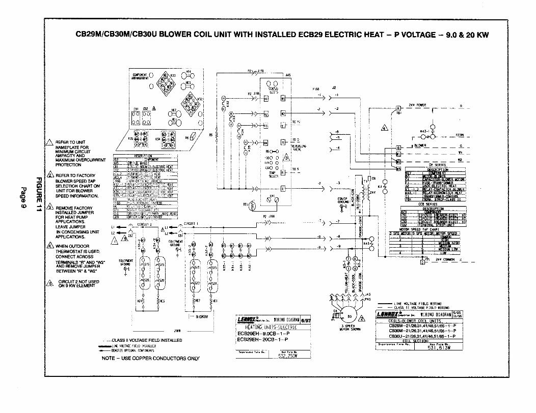
CB29M/CB30M/CB30UBLOWERCOIL UNITWITHINSTALLEDECB29ELECTRICHEAT - P VOLTAGE- 9.0 & 20 KW
_ REFER TO UNITNAMEPLATE FORMINIMUM CIRCUITAMPACITY ANDMAXIMUM OVERCURRENTPROTECTION
REFER TO FACTORY
BLOWER SPEED TAPSELECTION CHART ONUNIT FOR BLOWER
SPEED INFORMATION.
_ REMOVE FACTORYINSTALLED JUMPERFOR HEAT PUMPAPPLICATIONS,LF.JWE JUMPER
IN CONDENSING UNITAPPLICATIONS.
_WHEN OLKIX)OR
THERMOSTAT IS USED,
CONNECT ACROSS
TERMINALS =R* AND "W2"AND REMOVE JUMPERBEIWEEN "R" & "W2*
CIRCUIT 2 NOT USEDON 9 KW ELEMENT
PI{,6 J2

K:I
CB29M/CB30M/CB30U BLOWER COIL UNIT WITH INSTALLED ECB29 ELECTRIC HEAT - P VOLTAGE - 12.5 & 15 KW
_ REFER TO UNITNAMEPLATE FORMiNiMUM CIRCUITAMPACITY ANDMAXIMUM OVERCURRENTPROTECTION
/_ REFER TO FACTORY
BLOWER SPEED TAPSELECTION CHART ONUNIT FOR BLOWERSPEED INFORMATION,
/_ REMOVE FACTORY
INSTALLED JUMPERFOIl HEAT PUMPAPPUCATIONS.
LEAVE JUMPER
IN CONDENSING UNiTAPPLICATIONS.
_WHEN OUTDOOR
THERMOSTAT IS USED,CONNECT ACROSS
TERMINALS "R" AND =W2"AND REMOVE JUMPERBETWEEN "R" & "W2"
-- --CLASS II VOLTAGE FIELD INSTALLED
_LI_ V_lkSE EIEtOINSTALLED
NOTE - USE COPPER CONDUCTORS ONLY
ILB#IBI,_,,,.,..liFE16
HEATINGUNITS-ELECTRIC
ECB29EH- 12.5CB- 1 - P i
i ECB29EH - 15CB - t - P
532,582W
2€V pGli_R R
P*3
p
IdOTOR5H(3'lf_
[_TOR SPEED "rAP CHART
-_ ZCV CBVt_0N C
LIN_ VOLTAGE FIEIO WIRINGCLA_S IT VOLTAGE FIELD WIRINB
H s/gsLI_IN_X_*._,.x. IIRI 6 DIAGRAH (o/9s)
COILS-BLOYIER COIL UNITS i
CB29M-21/26,31,41/46,51/65-1 -PCB30M-21/2_,31,41/46,51/65-1 -PCB3OU -21/26,31,41/46,51/65-1 -P
i COIL _CTION-
s.,,,.,., r...., ( 531,613W='"r.. N.. (
*_9 > f
"-- ..... "-'
CB 4. I_,_pi,_TI_R-I_L_R I_ITOR
K3 _,12 MAC_-ELECTRICH AT
/ " i_ > ; Z4v _ I.L^Y*E(mNOulzER HE*T I
ii_['_ ECB S_L_IED
/ _ ! _T82 ITER_IIiN_LSTRIP-LINIT j

m

K_
CB31MV BLOWER COIL UNIT WITH INSTALLED ECB29 ELECTRIC HEAT - P-VOLTAGE - 12.5 & 15 KW
=to DB_ _ K_
A RE_RTOU.ITI_!_l_TE,O_ )iOOi_ _ OIMINIMUM CIRCUIT _ --
MAXIMUM OVERCURRENTPROTECTION K34 t:_
Z_ REFER TO F/_-_TORY _i(_i
BLOWER SPEED TAP _T_IPTION iSELECTION CHART ON _EY i C_h_Nl
bk45 _IROL_LE --'_)UNIT FOR B LO VIrF_R , _ _
REMOVE FACTORYiNSTALLED JUMPERFOR HEAT PUMPAPPUCAllONS,LEAVE JUMPER
IN CONDENSING UNffAPPUC_T1ONS,
/_ WHEN OLITIX)ORTHERMOSTAT IS USED,
CONNECT ACR06S
TERMINALS "R" AND =W2"AND REMOVE JUMPERBETWEEN "R" & "W2*
'b_ m-_ ,,_
iooiiI STATU'£P2 Jle_ LEO'S [
! ,,_ ^ )v,._e( ,oooo( _,io o ) (i TE_PIR)- _-- --
_LECT --i L
i OAT i
_ . 0,,0r,le,o!)LEJ_'X,,_=.......|IR]XG
i_'ING UNITSELECTRIC
I ECB29EH - 12.5CB- I - P
ECB29EH- 15CB- I -P
IIIH{NI'&IiIOITYCONTROL (k2'O) 15 NOT _ INCOWBINATIDN TilTH TlmilOSPF.F.O_5011,CLW'iECT JUk_ER BE_€ "Y2" AND "(_3"
i/_ _'_N HUMIDITY CONTROL (kZO IS NOt Ur_ INCOk_BIN_TIO_ WITH SINOLE ISLED CO_RE&_.
CD_WECT JUI_=ER _Tt_EN "YI" ANO "OS =
_,,..,,, _or,,,.) 532,582W_'r., ,,.
_LASS IIVOLTAGE FIELD INSTALLED
mLIN_ VOLT_E FIELD INSTALLED
_NOIES OPTI(}_kLCO_NIS
NOTE - USE COPPER CONDUCTORS ONLY
)