tbr 21 - edition 01 - attachment requirements for pan - etsi
TRANSCRIPT
TECHNICAL TBR 21
BASIS for January 1998
REGULATION
Source: ATA Reference: DTBR/ATA-005055
ICS: 33.020
Key words: PSTN, terminal equipment
Terminal Equipment (TE);Attachment requirements for pan-European approval
for connection to the analogue Public Switched TelephoneNetworks (PSTNs) of TE (excluding TE supporting the voice
telephony service) in which network addressing, if provided, isby means of Dual Tone Multi Frequency (DTMF) signalling
ETSI
European Telecommunications Standards Institute
ETSI Secretariat
Postal address: F-06921 Sophia Antipolis CEDEX - FRANCEOffice address: 650 Route des Lucioles - Sophia Antipolis - Valbonne - FRANCEX.400: c=fr, a=atlas, p=etsi, s=secretariat - Internet: [email protected]
Tel.: +33 4 92 94 42 00 - Fax: +33 4 93 65 47 16
Copyright Notification: No part may be reproduced except as authorized by written permission. The copyright and theforegoing restriction extend to reproduction in all media.
© European Telecommunications Standards Institute 1998. All rights reserved.

Page 2TBR 21: January 1998
Whilst every care has been taken in the preparation and publication of this document, errors in content,typographical or otherwise, may occur. If you have comments concerning its accuracy, please write to"ETSI Editing and Committee Support Dept." at the address shown on the title page.

Page 3TBR 21: January 1998
Contents
Foreword .......................................................................................................................................................7
Introduction....................................................................................................................................................9
1 Scope ................................................................................................................................................11
2 Normative references........................................................................................................................11
3 Definitions and abbreviations ............................................................................................................123.1 Definitions ..........................................................................................................................12
3.1.1 General terms................................................................................................123.1.2 States ............................................................................................................13
3.2 Abbreviations .....................................................................................................................13
4 Requirements....................................................................................................................................144.1 General requirement..........................................................................................................144.2 Physical characteristics of the connection to the PSTN ....................................................144.3 Requirements under all conditions ....................................................................................15
4.3.1 Polarity...........................................................................................................154.4 General requirements in quiescent state ...........................................................................15
4.4.1 DC resistance................................................................................................154.4.2 Characteristics of TE for ringing signals........................................................15
4.4.2.1 Impedance...........................................................................154.4.2.2 Transient response..............................................................154.4.2.3 DC current ...........................................................................16
4.4.3 Impedance unbalance about earth................................................................164.4.4 Resistance to earth .......................................................................................16
4.5 Ringing signal detector sensitivity ......................................................................................174.6 Transition from quiescent to loop state..............................................................................17
4.6.1 Acceptance of breaks in the loop in a call attempt........................................174.6.2 Loop current characteristics ..........................................................................18
4.7 General loop steady state requirements............................................................................194.7.1 DC characteristics .........................................................................................194.7.2 Impedance.....................................................................................................204.7.3 Sending level limitations................................................................................21
4.7.3.1 Mean sending level..............................................................214.7.3.2 Instantaneous voltage..........................................................214.7.3.3 Sending level in a 10 Hz bandwidth.....................................214.7.3.4 Sending level above 4,3 kHz ...............................................22
4.7.4 Impedance unbalance about earth................................................................234.7.4.1 Longitudinal Conversion Loss..............................................234.7.4.2 Output Signal Balance .........................................................23
4.7.5 Resistance to earth .......................................................................................244.8 Call attempt........................................................................................................................24
4.8.1 Automatic dialling ..........................................................................................244.8.1.1 Dialling without dial tone detection.......................................244.8.1.2 Dialling with dial tone detection............................................25
4.8.2 DTMF signalling ............................................................................................254.8.2.1 Frequency combinations......................................................254.8.2.2 Signalling levels ...................................................................25
4.8.2.2.1 Absolute levels......................................254.8.2.2.2 Level difference ....................................26
4.8.2.3 Unwanted frequency components .......................................264.8.2.4 Tone duration.......................................................................264.8.2.5 Pause duration.....................................................................26
4.8.3 Automatically repeated call attempts.............................................................264.9 Transition from loop to quiescent state..............................................................................27

Page 4TBR 21: January 1998
4.10 Safety ................................................................................................................................ 274.11 EMC .................................................................................................................................. 27
Annex A (normative): Test methods ..................................................................................................... 28
A.1 General ............................................................................................................................................. 28A.1.1 Equipment connection....................................................................................................... 28A.1.2 Test environment .............................................................................................................. 28A.1.3 Powered state ................................................................................................................... 29A.1.4 Measurements to earth ..................................................................................................... 29A.1.5 Equivalent test methods.................................................................................................... 29A.1.6 Additional information to support the test.......................................................................... 29
A.2 Test impedances .............................................................................................................................. 30A.2.1 Reference impedance ....................................................................................................... 30A.2.2 Non-reactive line termination............................................................................................. 30
A.3 Feeding bridge.................................................................................................................................. 30
A.4 Test methods.................................................................................................................................... 30A.4.1 General requirement ......................................................................................................... 30A.4.2 Physical characteristics of connection to the PSTN.......................................................... 30A.4.3 Requirements in all conditions .......................................................................................... 31
A.4.3.1 Polarity .......................................................................................................... 31A.4.4 General requirements in quiescent state .......................................................................... 31
A.4.4.1 DC Resistance.............................................................................................. 31A.4.4.2 Characteristics of TE for ringing signals ....................................................... 32
A.4.4.2.1 Impedance .......................................................................... 32A.4.4.2.2 Transient response ............................................................. 33A.4.4.2.3 DC current........................................................................... 33
A.4.4.3 Impedance unbalance about earth ............................................................... 34A.4.4.4 Resistance to earth....................................................................................... 35
A.4.5 Ringing signal detector sensitivity ..................................................................................... 36A.4.6 Transition from quiescent to loop state ............................................................................. 37
A.4.6.1 Acceptance of breaks in the loop in a call attempt ....................................... 37A.4.6.2 Loop current characteristics ......................................................................... 37
A.4.7 General loop state requirements....................................................................................... 38A.4.7.1 DC characteristics......................................................................................... 38A.4.7.2 Impedance.................................................................................................... 39A.4.7.3 Sending level limitations ............................................................................... 40
A.4.7.3.1 Mean sending level ............................................................. 40A.4.7.3.2 Instantaneous voltage......................................................... 41A.4.7.3.3 Sending level in a 10 Hz bandwidth .................................... 42A.4.7.3.4 Sending level above 4,3 kHz............................................... 43
A.4.7.3.4.1 Sending level above 4,3 kHz duringDTMF dialling ....................................... 43
A.4.7.3.4.2 Sending level above 4,3 kHz duringcommunication ..................................... 44
A.4.7.4 Impedance unbalance about earth ............................................................... 45A.4.7.4.1 Longitudinal Conversion Loss ............................................. 45A.4.7.4.2 Output Signal Balance ........................................................ 46
A.4.7.5 Resistance to earth....................................................................................... 47A.4.8 Call attempt ....................................................................................................................... 48
A.4.8.1 Automatic dialling.......................................................................................... 48A.4.8.1.1 Dialling without dial tone detection...................................... 48A.4.8.1.2 Dialling with dial tone detection........................................... 48
A.4.8.2 DTMF signalling............................................................................................ 49A.4.8.2.1 Frequency combinations..................................................... 49A.4.8.2.2 Signalling levels .................................................................. 50A.4.8.2.3 Unwanted frequency components ...................................... 51A.4.8.2.4 Tone duration...................................................................... 52A.4.8.2.5 Pause duration .................................................................... 54
A.4.8.3 Automatically repeated call attempts ............................................................ 55
Page 5TBR 21: January 1998
A.4.9 Transition from loop to quiescent state..............................................................................56
Annex B (normative): TBR Requirements Table (TBR-RT) ..................................................................57
B.1 Guidance for completion of the TBR-RT...........................................................................................57B.1.1 Condition table ...................................................................................................................57B.1.2 Requirements table............................................................................................................57
Annex C (informative): Bibliography........................................................................................................60
History..........................................................................................................................................................61

Page 6TBR 21: January 1998
Blank page

Page 7TBR 21: January 1998
Foreword
This Technical Basis for Regulation (TBR) has been produced by the ETSI Project Analogue Terminalsand Access (ATA).
The present document has been produced by ETSI in response to a mandate from the EuropeanCommission issued under Council Directive 83/189/EEC (as amended) laying down a procedure for theprovision of information in the field of technical standards and regulations.
The present document is intended to become a Harmonized Standard as requested by the abovementioned mandate, the reference of which will be published in the Official Journal of the EuropeanCommunities referencing the Council Directive on the approximation of the laws of the Member Statesconcerning telecommunications terminal equipment, including the mutual recognition of their conformity(Directive 91/263/EEC, known as "the TTE Directive").
A common technical regulation may be established by the European Commission in accordance with theDirective.
Technical specifications relevant to the 91/263/EEC Directive are given in the TBR-Requirements Table(TBR-RT) in annex B.
The voting phase for this TBR was undertaken on the understanding that the arrangements describedbelow will apply within the EU and that all necessary obligations will be laid down in any CommissionDecision for a Common Technical Regulation (CTR 21). These arrangements were agreed in a meetingof the ACTE Heads of Delegation on 16th September 1997.
It is the intention that a pan-European approval scheme using TBR 21 as the basis will be legitimised, butthe scheme will recognize that nationally, technical differences exist and are described in Advisory Notes.The Advisory Notes themselves will not be mandatory, however manufacturers will be encouraged toensure that their products conform to the relevant Advisory Notes. This recommendation will be reflectedin any Decision.
In the interests of transparency, the above mentioned Advisory Notes are contained in an ETSI Guide (EG201 121). This ETSI Guide in no way changes the voluntary nature of Advisory Notes either de jure or defacto. Initially, all Advisory Notes have been included and the adoption of the ETSI Guide has taken placein parallel to the adoption of this TBR.
The maintenance of both the TBR and the ETSI Guide will follow the normal ETSI maintenanceprocedures, based on experience.
Page 8TBR 21: January 1998
Transition Arrangements
A transition period of 12 months will permit parallel approval procedures for equipment falling within thescope of the CTR. Thereafter national approvals for new equipment falling within the scope of the CTR willnot be permitted. However, national approvals may continue for equipment intended for applicationsoutside the scope of the CTR, e.g. terminals intended for series or parallel connection. Only suchequipment may be marked with national marks. Equipment, falling within the scope of TBR 21, andapproved against national regulations before the end of the transition period may continue to be placed onthe market after the end of the transition period.
Obligations of the manufacturer
a) During the transition period, manufacturers will be obliged to associate a notice with allpan-European approval products.
The text of this notice is proposed as follows:
"The equipment has been approved to [Commission Decision “CTR 21”] for pan-European singleterminal connection to the Public Switched Telephone Network (PSTN). However, due todifferences between the individual PSTNs provided in different countries the approval does not, ofitself, give an unconditional assurance of successful operation on every PSTN networktermination point.
In the event of problems, you should contact your equipment supplier in the first instance."
The manufacturer should ensure that the seller and user of the equipment is clearly informed ofthe above information by means of packaging and/or user-manuals.
The necessity of continuing to oblige manufacturers to use this notice after the transition periodhas expired, shall be subject to a review in ACTE, based on experience with the CommissionDecision.
b) In addition, manufacturers must make a network compatibility declaration to the Notified Body, theseller and user.This declaration will indicate the networks with which the equipment is designed to work and anynotified networks with which the equipment may exhibit interworking difficulties.
The manufacturer shall also make it clear where network compatibility is dependent on physicaland software switch settings.
Obligations of the Notified Body
Notified Bodies shall ensure that the manufacturer complies with the provisions of the paragraph coveringthe obligations of the manufacturer and that the network compatibility declarations referred to in a) and b)above are made in the correct form.
The Notified Bodies should also ensure that manufacturers are aware of the applicable Advisory Notesconcerning the specific requirements of certain networks.
The Notified Body does not evaluate equipment against applicable Advisory Notes, since they arevoluntary. The role of the Notified Body in this respect is to clarify with the manufacturer the intendedpurpose of the equipment.
During the transition period the National Authorities shall ensure that the Notified Bodies inform otherNotified Bodies of the network compatibility declarations whenever the approval is granted.

Page 9TBR 21: January 1998
Introduction
The existing analogue presentation of Public Switched Telephone Networks (PSTNs) in Europeancountries are technically somewhat different, due to historical reasons. The services being offered to theend users also differ to a certain extent.
The increasing use of analogue terminals in the European networks, and especially terminals offeringnon-voice services, such as modems and facsimile, is a measure of the need for such equipment seen byEuropean business companies. This type of equipment is undergoing constant and rapid development,and it is therefore imperative that the delay in, and cost of, market introduction caused by the approvalprocedures is the minimum possible. Otherwise, new innovative products may be available to Europe atlater dates than to other regions in the world. Also, countries in Europe where the market is comparativelysmall may never benefit from these products, if the cost of market introduction is too high.
According to Directive 91/263/EEC, Terminal Equipment (TE) is required, among other things, to:
- not cause harm to the network - Article 4(d);
- be able to interwork with the network in order to set up, hold, modify, charge for and clear down aconnection - Article 4(f);
- interwork via the public telecommunications network, in justified cases - Article 4(g).
Although different, the networks have some basic commonalities. By restricting the requirements to coveronly the interworking that is essential for the establishment of a call to/from a terminal, the signallingaspects can be simplified and harmonized.
This TBR specifies a harmonized set of requirements which will allow terminals, excluding voice telephonyterminals subject to Article 4(g) requirements, to be analogue connected to the existing European PSTNs.It covers all relevant essential requirements in Directive 91/263/EEC. All safety requirements are coveredby the Low Voltage Directive (LVD) and therefore there are no requirements for Articles 4(a) and 4(b). AllElectroMagnetic Compatibility (EMC) requirements are covered by the EMC Directive and therefore norequirements for Articles 4(c) are included in this TBR. Article 4(e) is not applicable for a non-radiosystem. Article 4(g) is not applicable for non-voice terminals.
This TBR specifies the connection arrangements (plug or socket, of the supplier’s choice) to be providedby the terminal equipment. An adapter may be required between the terminal and the existing nationalnetwork termination point in individual countries. Such an adapter is outside the scope of this TBR.
The pan-European approval requirements for TE access to an analogue presented PSTN are related tothe network's capabilities. A single terminal may consume all of this (given) capability, or it can be sharedby a number of terminals all being connected to the Network Termination Point (NTP) in an arbitrarycombination of parallel and/or series connections. In this case the performance of each individual terminalwill need to be better than required by this TBR to ensure satisfactory interworking with the network.Connection of terminal equipment in series and/or parallel is a national matter. Guidance on this subjectcan be found in EG 201 120.

Page 10TBR 21: January 1998
Blank page

Page 11TBR 21: January 1998
1 Scope
This Technical Basis for Regulation (TBR) specifies the technical characteristics (electrical andmechanical interface requirements and access control protocol) under Articles 4(d) and 4(f) of Directive91/263/EEC to be provided by a single Terminal Equipment (TE) which is:
- intended for pan-European approval; and
- capable of 2-wire access to an analogue Public Switched Telephone Network (PSTN) line at theNetwork Termination Point (NTP); but
- excluding TE which is capable of supporting the voice telephony justified case service as specifiedin Article 4(g) of Directive 91/263/EEC.
The objective of this TBR is to ensure that no harm occurs to the public network, and to ensureinterworking between network and terminal so that calls can be routed successfully through the network,but without any guarantee of terminal to terminal interoperability. There are no requirements in this TBRunder Article 4(g) of Directive 91/263/EEC.
This TBR covers TE which is capable of originating a circuit-switched call using Dual Tone MultiFrequency (DTMF) signalling and/or receiving an incoming circuit-switched call. Other signalling methods(e.g. loop disconnect signalling), if provided in the terminal and intended to be used in certain Europeancountries, are subject to appropriate national regulations in addition to this TBR, in respect of that feature.Also, signalling for supplementary features (e.g. register recall, reception of metering pulses from thenetwork) if provided in the terminal, and intended to be used in certain European countries, are subject tothe appropriate national regulations.
For each requirement in this TBR a test is given, including measurement methods. Requirements apply atthat interface of the TE which connects directly (by galvanic means) to the PSTN via a network terminationpoint. The TE may be stimulated to perform the test by additional equipment if necessary.
This TBR specifies the connection arrangements (plug or socket, of the supplier's choice) to be providedby the TE. An adapter may be required between the terminal and the existing national network terminationpoint in individual countries. Such an adapter is outside the scope of this TBR.
Where the origination or reception of calls by the TE is invoked, or otherwise controlled, by otherequipment external to the TE, the TE still needs to be capable of fulfilling the essential requirements underArticles 4d) and 4f) at the interface to the public network. This TBR requires the manufacturer or supplierof the TE to declare the conditions met by such external devices so that their use does not cause the TEto fail to meet the essential requirements.
2 Normative references
This TBR incorporates by dated and undated reference, provisions from other publications. Thesenormative references are cited at the appropriate places in the text and the publications are listedhereafter. For dated references, subsequent amendments to or revisions of any of these publicationsapply to this TBR only when incorporated in it by amendment or revision. For undated references thelatest edition of the publication referred to applies.
[1] Miniature 6-position plug as described in FCC 47, CFR 68.500: "Code ofFederal Regulations (USA); Title 47 Telecommunication; Chapter 1 FederalCommunications Commission, Part 68 Connection of Terminal Equipment to theTelephone Network; Subpart F Connectors; Section 68.500 Specification".
NOTE: The above document can be obtained from:
Superintendent of DocumentsWashington DC 20402United StatesTel: + 1 202 512 18003

Page 12TBR 21: January 1998
[2] CCITT Recommendation G.117 (1990): "Transmission aspects of unbalanceabout earth (definitions and methods)".
[3] ITU-T Recommendation G.100 (1993): "Definitions used in Recommendationson general characteristics of international telephone connections and circuits".
3 Definitions and abbreviations
3.1 Definitions
For the purposes of this TBR, the following definitions apply:
3.1.1 General terms
automatic repeat call attempts: An automatic repeat call attempt made by the TE to the same networkaddress as the result of the failure of the previous call attempt and not as a result of an external stimulusto the TE.
call attempt: The process by which the TE seizes the PSTN line and sends signalling characters of thenetwork address with which the TE wishes to communicate.
connection to earth: Connection to earth means that all the following points, as applicable are connectedto the earth point during measurement:
- a point in the TE which is intended to be connected to mains earth (in practice this might becarried out by connecting to the earth of the mains source which is supplying the TE);
- connector points which are intended to be connected to earth during the normal operation ofthe apparatus.
dBV: Absolute voltage level expressed in decibels with respect to 1 volt.
Longitudinal Conversion Loss: As described in CCITT Recommendation G.117 [2] subclause 4.1.3.
Network Termination Point (NTP): The physical point at the boundary of the PSTN intended to acceptthe connection of a TE. See figure 1.
Output Signal Balance (OSB): As described in CCITT Recommendation G.117 [2] subclause 4.3.1.
peak to peak voltage: Peak to peak voltage in this TBR is the difference between the maximum andminimum voltage during any 10 ms window.
Public Switched Telephone Network (PSTN): The term is used to describe the ordinary telephonesystem including subscriber lines, local exchanges and the complete system of trunks and the exchangehierarchy which makes up the network.
reference impedance Z R: A complex impedance made up of 270 ohms in series with a parallelcombination of 750 ohms and 150 nF. This is shown in annex A, figure A.1.
repeat call attempt: A further call attempt to the same network address resulting from a failure toestablish connection during the previous call attempt.
repeat call attempt sequence: A series of internally generated automatic repeat call attempts made inresponse to an initial call attempt.
NOTE 1: Additional, but separate, call requests are permitted to initiate separate repeat callattempt sequences.
return loss: As described in ITU-T Recommendation G.100 [3] subclause 1.5.

Page 13TBR 21: January 1998
Terminal Connection Point (TCP): The point of the TE intended to be connected to the PSTN. Anadapter may be required between the terminal and the existing national network termination point inindividual countries. Such an adapter is outside the scope of this TBR (see figure 1).
Suitable adapter and/orinstallation facilities
TE
TCPNTP
TBR 21interface
Nationalinterface
PSTN
Figure 1: Terminal Connection Point and Network Termination Point
Terminal Equipment (TE): Equipment intended to be connected to the public telecommunicationnetwork; i.e.:
- to be connected directly to the termination of a public telecommunication network; or- to interwork with a public telecommunication network being connected directly or indirectly to the
termination of a public telecommunication network,
in order to send, process or receive information. The system of connection may be wire, radio, optical orother electromagnetical system.
NOTE 2: This definition is copied from the Directive 91/263/EEC.
3.1.2 States
loop state: The state where the TE draws sufficient DC current to activate the exchange.
loop steady state: A loop state excluding the transitions from and to quiescent state.
quiescent state: The state where the TE draws insufficient DC current to activate the exchange.
3.2 Abbreviations
For the purposes of this TBR, the following abbreviations apply:
AC Alternating CurrentADSI Analogue Display Services InterfaceDC Direct CurrentDTMF Dual Tone Multi-FrequencyEMC ElectroMagnetic CompatibilityLCL Longitudinal Conversion LossLVD Low Voltage DirectiveNTP Network Termination PointOSB Output Signal BalancePSTN Public Switched Telephone Networkrms root mean squareSCWID Spontaneous Call Waiting IdentificationTCP Terminal Connection PointTBR-RT TBR Requirements TableTE Terminal Equipment

Page 14TBR 21: January 1998
4 Requirements
The TE shall comply with the provisions of this TBR when tested via contact pins 3 and 4 as shown intable 1.
NOTE 1: The pan-European approval requirements for TE access to an analogue presentedPSTN are related to the network's capabilities. A single terminal may consume all ofthis (given) capability, or it can be shared by a number of terminals all being connectedto the NTP in an arbitrary combination of parallel and/or series connections. In thiscase the performance of each individual terminal will need to be better than requiredby this TBR to ensure satisfactory interworking with the network. Connection ofterminal equipment in series and/or parallel is a national matter. Guidance on thissubject can be found in EG 201 120.
NOTE 2: The feeding voltage value of 50 VDC in the requirement and test parts is only aharmonized test value. It does not necessarily reflect the real PSTN supply voltages.
4.1 General requirement
Justification: Where the origination or reception of calls by the TE is invoked, or otherwise controlled byother equipment external to the TE, the TE shall still be capable of fulfilling the essential requirementsunder Articles 4(d) and 4(f) of Directive 91/263/EEC at the interface to the public network.
Requirement: Where the origination or reception of calls by the TE is invoked, or otherwise controlled byother equipment external to the TE, the manufacturer or supplier of the TE shall declare the conditionsthat need to be met by such external devices so as to enable the user to ensure that their use does notcause the TE to fail to meet the essential requirements.
Test: By confirming the presence of such declaration.
4.2 Physical characteristics of the connection to the PSTN
Justification: 91/263/EEC, Article 4(f); Interworking with the PSTN is assured by requiring the TE tointerwork with different European networks, where different features may be offered, but where allnetworks can perform the basic interworking on two wires. To facilitate the use of adapters, the TErequires a known type of connection arrangement.
Requirement: The TE shall provide a connector either as a plug or as a socket. The connector, if a plug,shall be capable of connecting with a miniature 6-position socket as specified in FCC 47, CFR 68.500 [1]clause (b) and if a socket, shall be capable of connecting with a miniature 6-position plug as specified inFCC 47, CFR 68.500 [1] clause (a).
NOTE 1: The TE may include a means (e.g. a lead) which adapts an interface of the TE to theconnector described in this clause upon which the TCP is presented. Therequirements of this TBR apply at the TCP and this means is considered to be anintegral part of the TE.
NOTE 2: This connector is often referred to as RJ 11/12.
Table 1: Contact assignments
Contact number Contact function1 Unspecified2 Unspecified3/4 TCP5 Unspecified6 Unspecified
Test: By visual inspection. The interworking capability shall be verified through the tests in annex A.

Page 15TBR 21: January 1998
4.3 Requirements under all conditions
4.3.1 Polarity
Justification: 91/263/EEC, Article 4(f); Interworking with the PSTN is assured by requiring the TE tooperate with both polarities, since a fixed polarity is not guaranteed.
Requirement: The TE shall conform to the requirements of this TBR for both polarities of line feedingvoltage.
Test: Where tests with both polarities are needed this is indicated in relevant clauses in annex A.
4.4 General requirements in quiescent state
4.4.1 DC resistance
Justification: 91/263/EEC, Article 4(f); Interworking with the PSTN is assured by requiring the TE topresent a sufficiently high DC resistance in quiescent state so as not to disturb the basic call control and toprevent the malfunction of network call control equipment.
Requirement: The current drawn by the TE when connected to a source of:
- 100 VDC;- 50 VDC;- 25 VDC,
shall not exceed that which would be drawn by a 1 MΩ resistor replacing the TE. This requirement applies30 seconds after the voltage has been applied.
Test: The test shall be conducted according to annex A, subclause A.4.4.1.
4.4.2 Characteristics of TE for ringing signals
4.4.2.1 Impedance
Justification: 91/263/EEC, Article 4(f); Interworking with the PSTN is assured by requiring the TE topresent an impedance to ringing signals that is sufficiently high.
Requirement: The impedance of the TE at frequencies of 25 Hz and 50 Hz shall not be less than 4 kΩwhen tested at 30 V rms.
Test: The test shall be conducted according to annex A, subclause A.4.4.2.1.
4.4.2.2 Transient response
Justification: 91/263/EEC, Article 4(f); Interworking with the PSTN is assured by limiting the currenttransient at the beginning of a ringing signal.
Requirement: When ringing signals are applied to the terminal equipment in the quiescent state, theresulting current shall not cause the public exchange to detect a loop state. This shall be verified by DCexcitation of the TE in quiescent state. The current shall be equal to or less than 25 mA, 1 ms aftercommencement of the excitation, and equal to or less than 10 mA, 6 ms after commencement.
Test: The test shall be conducted according to annex A, subclause A.4.4.2.2.
Page 16TBR 21: January 1998
4.4.2.3 DC current
Justification: 91/263/EEC, Article 4(f); Interworking with the PSTN is assured by requiring the TE to avoidcreating DC current due to asymmetric load of the ringing signal (e.g. caused by the use of overvoltagearrestors). This requirement avoids false seizure of the PSTN.
Requirement: The resulting DC current during the ringing signal, tested with a 25 Hz and 50 Hz AC signalat a voltage of 90 V rms superimposed on a DC voltage of 60 V, shall be less than 0,6 mA.
Test: The test shall be conducted according to annex A, subclause A.4.4.2.3.
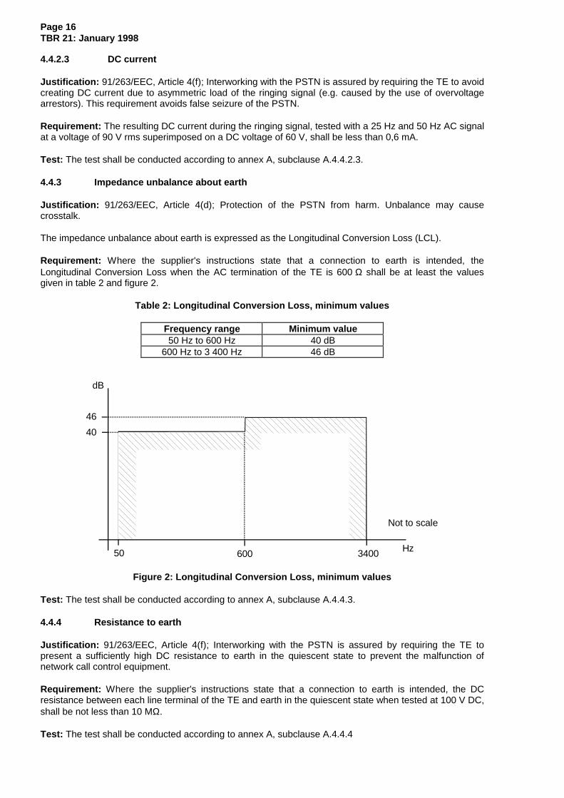
4.4.3 Impedance unbalance about earth
Justification: 91/263/EEC, Article 4(d); Protection of the PSTN from harm. Unbalance may causecrosstalk.
The impedance unbalance about earth is expressed as the Longitudinal Conversion Loss (LCL).
Requirement: Where the supplier's instructions state that a connection to earth is intended, theLongitudinal Conversion Loss when the AC termination of the TE is 600 Ω shall be at least the valuesgiven in table 2 and figure 2.
Table 2: Longitudinal Conversion Loss, minimum values
Frequency range Minimum value50 Hz to 600 Hz 40 dB
600 Hz to 3 400 Hz 46 dB
40
46
dB
50 600 3400 Hz
Not to scale
Figure 2: Longitudinal Conversion Loss, minimum values
Test: The test shall be conducted according to annex A, subclause A.4.4.3.
4.4.4 Resistance to earth
Justification: 91/263/EEC, Article 4(f); Interworking with the PSTN is assured by requiring the TE topresent a sufficiently high DC resistance to earth in the quiescent state to prevent the malfunction ofnetwork call control equipment.
Requirement: Where the supplier's instructions state that a connection to earth is intended, the DCresistance between each line terminal of the TE and earth in the quiescent state when tested at 100 V DC,shall be not less than 10 MΩ.
Test: The test shall be conducted according to annex A, subclause A.4.4.4
Page 17TBR 21: January 1998
4.5 Ringing signal detector sensitivity
Justification: 91/263/EEC, Article 4(f); Interworking with the PSTN is assured by requiring the TE todetect valid ringing signals.
Requirement: If a ring detect function is provided and enabled, the TE shall be able to respond to ringingsignals of 30 V rms at 25 Hz and 50 Hz with a cadence of 1 s ON and 5 s OFF, superimposed on a50 VDC feeding voltage.
The response shall be as stated by the supplier.
Test: The test shall be conducted according to annex A, subclause A.4.5.
NOTE 1: For example, a TE might:
- generate a signal denoting an incoming call in accordance with the supplier’sinstructions; or
- be configured to seize the line according to subclause 4.6.
NOTE 2: A TE designer should be aware that a number of different ringer voltages, frequencies,harmonic contents and cadences are in use, and more are likely to be brought into usewithin the countries of Europe. Also, non-polarized ringing signals exist. To ensureoperation within the countries in which the TE is intended to be used, the designer willneed to choose the appropriate combination of parameters. An incorrect choice ofparameters could lead to unsatisfactory operation.
A TE with a ringing detector facility should be capable of responding to all the ringingvoltages, frequencies and cadences in Europe. This could be achieved by either, theTE having a single universal mode of operation, or by the TE having a number ofselective modes of operation, which together embrace the range of ringing conditions.
NOTE 3: In some countries the PSTN generates signals as low as 24 V rms. Particularly forelectro-acoustic ringers without local power supply, It is recognized that this voltagemay be insufficient to produce an acoustic output expected from some users orsuitable for applications in noisy surroundings.
NOTE 4: PSTN test signals and unintended induction from power lines may cause significantsignal levels to appear on the line. Such conditions may cause incorrect interworking, ifthe TE does not provide sufficient immunity.
4.6 Transition from quiescent to loop state
4.6.1 Acceptance of breaks in the loop in a call attempt
Justification: 91/263/EEC, Article 4(f); Interworking with the PSTN is assured by requiring the TE toaccept breaks in the loop current during establishment of loop state.
Requirement: If, during the transition from quiescent to the loop state for the purpose of making a call,the line feeding current has first reached and remained at a value greater than 12,8 mA for a duration ofbetween 30 ms and 500 ms, the current is interrupted for a period of 400 ms. When the source of thefeeding current is reconnected:
- the line current shall have reached a value greater than 12,8 mA within 20 ms of the reconnectionof the feeding source;
- during the period between 20 ms and 100 ms following the reconnection of the feeding source, thecurrent shall not drop below 12,8 mA for more than 7 ms. For the purpose of this requirement, anyperiods during which the current is less than 12,8 mA are aggregated and the total shall not exceedthe limit stated.
This requirement applies when the line feeding current is provided by a source of 50 V DC in series with aresistance of 850 Ω.

Page 18TBR 21: January 1998
Test: The test shall be conducted according to annex A, subclause A.4.6.1.
4.6.2 Loop current characteristics
Justification: 91/263/EEC, Article 4(f); Interworking with the PSTN is assured by requiring the TE to seizethe line.
Requirement: The loop current determined by the TE shall:
a) exceed the value of If1 before t1 after the seizure; andb) remain above If1 for at least a further (t2 - t01) time; andc) remain above If2 between t2 and t3, for conditions of the table 4 and figure 4.
The limit values (t1 - t0), (t2 - t01), (t3 - t01), If1 and If2 are given in tables 3 and 4 and shown in figures 3and 4 and:
- « t0 » is the reference moment of seizure, when the loop current exceeds 0,1 mA for the first timewith a feeding voltage of 50 VDC and stays above this value for more than 5 ms;
- « t01 » is the reference moment, when the loop current exceeds the current If1 for the first time witha feeding voltage of 50 VDC and stays above this value for more than 5 ms; and
- transient periods are permitted during which the loop current drops below the limits stated in thisclause, as long as when aggregated, they do not exceed 7 ms.
Table 3: TE current characteristics with feeding resistorswhich are not used during the loop steady state
Condition RequirementsFeedingvoltage
Feedingresistance
Time (ms) Current (mA)
Vf Rf t1 - t0 t2 - t01 If150VDC 150 kΩ. 400 400 0,3050VDC 36 kΩ. 400 400 1,2550VDC 24 kΩ. 400 400 1,8650VDC 8 kΩ. 400 400 5,00
0,1
t01
I (mA)
t 0 t 2
Not to scale
If 1Example of TE behaviour
t 1
Figure 3: TE current characteristics with feeding resistorswhich are not used during the loop steady state

Page 19TBR 21: January 1998
Table 4: TE current characteristics with feeding resistorswhich are used during the loop steady state
Condition RequirementsFeedingvoltage
Feedingresistance
Time (ms) Current (mA)
Vf Rf t1-t0 t2-t01 t3-t01 If1 If250VDC 3,2 kΩ 30 500 1 200 13,1 12,850VDC 230 Ω 20 500 1 200 49,6 49,6
0,1
t01
I (mA)
t 0 t 2
Not to scale
t 3
If 1
If 2
Example of TE behaviour
t 1
Figure 4: TE current characteristics with feeding resistorswhich are used during the loop steady state
Test: The test shall be conducted according to annex A, subclause A.4.6.2.
4.7 General loop steady state requirements
The requirements during the loop steady state apply when the TE has been in the loop state for aminimum of 1,2 s with a line feeding current which can be obtained when the TE is connected to a sourceof 50 VDC in series with a resistor within the range of 3 200 Ω to 230 Ω.
4.7.1 DC characteristics
Justification: 91/263/EEC, Article 4(f); Interworking with the European PSTN, some of which havingdifferent DC characteristics, is assured by requiring the TE to present a sufficiently low DC resistance inloop state.
Requirement: The DC voltage/current characteristics of the TE within the operating range as stated insubclause 4.7 shall not exceed the limits given in table 5 and shown in figure 5.

Page 20TBR 21: January 1998
Table 5: TE voltage/current characteristics
Point Voltage (V) Current (mA)A 9,0 0B 9,0 20,0C 14,5 42,0D 40,0 50,0E 40,0 60,0F 0 60,0G 0 0
NOTE: Limits for intermediate currents can be found by drawing astraight line between the break points on a linear voltage/currentscale.
0
9,0
14,5
0 6020 42 I (mA)
U(V)
A B
C
D E
F
40
Not to scale
50
G
Figure 5: TE voltage/current characteristics
Test: The test shall be conducted according to annex A, subclause A.4.7.1.
4.7.2 Impedance
Justification: 91/263/EEC, Article 4(f); Interworking with the PSTN is assured by requiring the TE topresent an impedance which allows proper functioning of call control and to maintain stability in the PSTN.
Requirement: The TE shall meet the following requirements:
- at frequencies greater than 300 Hz, but less than or equal to 4 000 Hz, the return loss calculatedwith respect to the reference impedance ZR (at the same frequency) shall not be less than 8 dB;and
- at frequencies that are greater than or equal to 200 Hz and less than or equal to 300 Hz:
a) the return loss calculated with respect to the reference impedance ZR (at the samefrequency) shall not be less than 6 dB; and
b) the reactive component of the impedance shall not be greater than 500 Ω inductive (+j 500).
Test: The test shall be conducted according to annex A, subclause A.4.7.2.
Page 21TBR 21: January 1998
4.7.3 Sending level limitations
4.7.3.1 Mean sending level
Justification: 91/263/EEC, Article 4(d); Protection of the PSTN from harm is assured by limiting thesignal sent into the PSTN by the TE so that the interfering effects of the signal can be predicted andavoided.
Requirement: The mean sending level in the frequency range 200 Hz to 3 800 Hz over a one-minuteperiod shall not be greater than -9,7 dBV when the TE interface is terminated with the referenceimpedance ZR. This requirement does not apply to DTMF signals.
Test: The test shall be conducted according to annex A, subclause A.4.7.3.1.
4.7.3.2 Instantaneous voltage
Justification: 91/263/EEC, Article 4(d); Protection of the PSTN from harm is assured by limiting thesignal sent into the PSTN by the TE so that the interfering effects of the signal can be predicted andavoided.
Requirement: The peak to peak voltage in the frequency range 200 Hz to 3 800 Hz shall not exceed5,0 volts when the TE interface is terminated with the reference impedance ZR.
Test: The test shall be conducted according to annex A, subclause A.4.7.3.2.
4.7.3.3 Sending level in a 10 Hz bandwidth
Justification: 91/263/EEC, Article 4(d); Protection of the PSTN from harm is assured by limiting thesignal sent into the PSTN by the TE so that the interfering effects of the signal can be predicted andavoided.
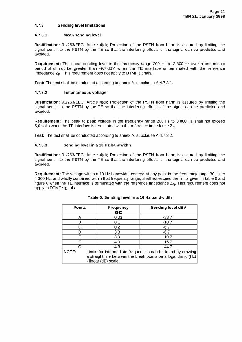
Requirement: The voltage within a 10 Hz bandwidth centred at any point in the frequency range 30 Hz to4 300 Hz, and wholly contained within that frequency range, shall not exceed the limits given in table 6 andfigure 6 when the TE interface is terminated with the reference impedance ZR. This requirement does notapply to DTMF signals.
Table 6: Sending level in a 10 Hz bandwidth
Points FrequencykHz
Sending level dBV
A 0,03 -33,7B 0,1 -10,7C 0,2 -6,7D 3,8 -6,7E 3,9 -10,7F 4,0 -16,7G 4,3 -44,7
NOTE: Limits for intermediate frequencies can be found by drawinga straight line between the break points on a logarithmic (Hz)- linear (dB) scale.

Page 22TBR 21: January 1998
0,03 0,1 0,2 3,8 3,9 4,3kHz
dBV
-16,7
-10,7
-6,7
-44,7
-33,7
Measurement bandwidth 10Hz
A
B
C D
E
F
4,0
G Not to scale
Figure 6: Sending level in a 10 Hz bandwidth
Test: The test shall be conducted according to annex A, subclause A.4.7.3.3.
4.7.3.4 Sending level above 4,3 kHz
Justification: 91/263/EEC, Article 4(d); Protection of the PSTN from harm is assured by limiting thesignal sent into the PSTN by the TE so that the interfering effects of the signal can be predicted andavoided.
Requirement : The total voltage level in a bandwidth, defined in table 7, wholly contained within thefrequency range 4,3 kHz to 200 kHz, arising from normal operation of the TE when in an on-line,non-dialling state, and when terminated with ZR, shall not exceed the limits shown in table 7 and figure 7.
During tone signalling the limits given in table 7 and figure 7 do not apply and are replaced by thefollowing:
In the range 4,3 kHz to 20 kHz, the individual level of any single frequency component shall not exceed-35,7 dBV.
In the range 20 kHz to 200 kHz, the individual level of any single frequency component shall not exceed-40,7 dBV.
NOTE: "Normal operation of the TE" is defined in the test, see annex A, subclause A.1.3.
Table 7: Sending level above 4,3 kHz
Points Frequency rangekHz
Sending level in a specifiedbandwidth
dBV
Measurementbandwidth
G to H 4,3 to 5,1 -40 decreasing to -44 300 HzH to I 5,1 to 8,9 -44 300 HzI to J 8,9 to 11 -44 decreasing to -58,5 300 HzJ to K 11 to 200 -58,5 1 kHz
NOTE: Limits for intermediate frequencies can be found by drawing a straight linebetween the break points on a logarithmic (Hz) - linear (dB) scale.

Page 23TBR 21: January 1998
-40
-44
-58,5
dBV
kHz4,3 5,1 8,9 200
G
H I
J K
300Hz 1kHz Measurementbandwidth
Maximum sending level (dBV)in measurement bandwidth
Not to scale
11
Figure 7: Sending level above 4,3 kHz
Test: The test shall be conducted according to annex A, subclauses A.4.7.3.4.1 and A.4.7.3.4.2.
4.7.4 Impedance unbalance about earth
Justification: 91/263/EEC, Article 4(d); Protection of the PSTN from harm. Unbalance may causecrosstalk.
The impedance unbalance about earth is expressed as Longitudinal Conversion Loss (LCL) when in thereceiving mode and Output Signal Balance (OSB) when in the transmitting mode.
4.7.4.1 Longitudinal Conversion Loss
Requirement: Where the supplier's instructions state that a connection to earth is intended, the LCLwhen the AC termination of the TE is 600 Ω shall be at least the values given in table 8 and figure 8.
Test: The test shall be conducted according to annex A, subclause A.4.7.4.1.
4.7.4.2 Output Signal Balance
Requirement: Where the supplier's instructions state that a connection to earth is intended, the OSBwhen the AC termination of the TE is 600 Ω shall be at least the values given in table 8 and figure 8. Thisrequirement only applies at frequencies where the unbalance level exceeds -70 dBV with the test methodshown in subclause A.4.7.4.2.
Table 8: Output Signal Balance and Longitudinal Conversion Loss, minimum values
Frequency range Minimum value50 Hz to 600 Hz 40 dB
600 Hz to 3 400 Hz 46 dB3 400 Hz to 3 800 Hz 40 dB

Page 24TBR 21: January 1998
40
46
dB
50 600 3400 Hz
Not to scale
3800
Figure 8: Output Signal Balance and Longitudinal Conversion Loss, minimum values
Test: The test shall be conducted according to annex A, subclause A.4.7.4.2.
4.7.5 Resistance to earth
Justification: 91/263/EEC, Article 4(f); Interworking with the PSTN is assured by requiring the TE topresent a sufficiently high DC resistance to earth in loop state so as not to disturb the basic call controlfunction.
Requirement: Where the supplier's instructions state that a connection to earth is intended, the DCresistance between each line terminal of the TE and earth in loop state when tested at 100 V DC shall benot less than 1 MΩ.
Test: The test shall be conducted according to annex A, subclause A.4.7.5.
4.8 Call attempt
All requirements in subclause 4.7 will also apply during a call attempt.
This clause only applies for terminals intended for outgoing calls.
4.8.1 Automatic dialling
This requirement applies only to a TE with an automatic seizing and dialling function. It applies when theTE is in automatic dialling mode.
4.8.1.1 Dialling without dial tone detection
Justification: 91/263/EEC, Article 4(f); Interworking with the PSTN is assured by requiring a TE withautomatic dialling to start sending its digits during the time period when the network is ready to receivedigits under normal conditions.
Requirement: The TE shall start dialling not earlier than 2,7 s and before 8 s has elapsed after the loopstate is established. Where adjustments are available to the user, resulting in a lower value, this isacceptable as long as the 2,7 s limit remains within the available range.
NOTE: It is recognized that, in some rare cases, the network may not be able to receivedialling signals within 3 s Also, some networks will not accept addressing informationafter 5 s has elapsed.
Test: The test shall be conducted according to annex A, subclause A.4.8.1.1.

Page 25TBR 21: January 1998
4.8.1.2 Dialling with dial tone detection
Justification: 91/263/EEC, Article 4(f); Interworking with the PSTN is assured by requiring a TE withautomatic dialling to start sending its digits during the time period when the network is ready to receivedigits.
Requirement: If the TE is intended for automatic dialling with an automatic dial tone detection, and thisfacility is enabled in accordance with the supplier's instruction, it shall start dialling within 8 s of the start ofthe application of:
- a continuous dial tone; and
- a cadenced dial tone whose cadence comprises a repeated sequence of:200 ms ON, followed by 200 ms OFF, followed by 600 ms ON, followed by 1 000 ms OFF.
For the purposes of this requirement, the dial tone is defined as a single tone signal, delivered from agenerator with a source impedance equal to ZR, in the frequency range 300 Hz to 500 Hz, whose level isbetween -35,7 dBV and -0,7 dBV when measured across the reference impedance ZR which substitutesthe TE.
Test: The test shall be conducted according to annex A, subclause A.4.8.1.2.
4.8.2 DTMF signalling
4.8.2.1 Frequency combinations
Justification: 91/263/EEC, Article 4(f); Interworking with the PSTN is assured by requiring the TE to senddigits that the network accepts.
Requirement: The TE shall use DTMF signalling characters according to table 9. However, the number ofcharacters supported by the TE can be restricted, in which case only those frequencies assigned to thesupported characters shall be used. The tolerances on the frequencies for the characters supported shallbe ± 1,5 %.
Table 9: DTMF signalling frequency combinations
Low groupHz
High groupHz
1 209 1 336 1 477 1 633697 1 2 3 A770 4 5 6 B852 7 8 9 C941 * 0 # D
Test: The test shall be conducted according to annex A, subclause A.4.8.2.1.
4.8.2.2 Signalling levels
4.8.2.2.1 Absolute levels
Justification: 91/263/EEC, Article 4(f); Interworking with the PSTN is assured by requiring the TE to senddigits that the network accepts.
Requirement: The level of any tone in the DTMF high frequency group shall be -9,0 dBV +2,0/-2,5 dB andthe level of any tone in the low frequency group shall be -11,0 dBV +2,5/-2,0 dB when the TE interface isterminated with the reference impedance ZR.
Test: The test shall be conducted according to annex A, subclause A.4.8.2.2.

Page 26TBR 21: January 1998
4.8.2.2.2 Level difference
Justification: 91/263/EEC, Article 4(f); Interworking with the PSTN is assured by requiring the TE to senddigits that the network accepts.
Requirement: During sending of any DTMF frequency combination, the level of the tone in the highfrequency group shall be 1 dB to 4 dB higher than the level of the tone in the low frequency group.
Test: The test shall be conducted according to annex A, subclause A.4.8.2.2.
4.8.2.3 Unwanted frequency components
Justification: 91/263/EEC, Article 4(f); Interworking with the PSTN is assured by requiring the TE to senddigits that the network accepts.
Requirement: When transmitting any DTMF tone combination during a call attempt, the total sendinglevel of all unwanted frequency components in the frequency range 250 Hz to 4 300 Hz shall be at least20 dB below the low frequency group component.
Test: The test shall be conducted according to annex A, subclause A.4.8.2.3.
4.8.2.4 Tone duration
This requirement applies where the DTMF signalling tone duration is controlled automatically by the TE.
Justification: 91/263/EEC, Article 4(f); Interworking with the PSTN is assured by requiring the TE to sendDTMF tones for a minimum period of time in order that the receivers in the exchange can recognize thedigit being sent.
Requirement: The TE shall provide a setting whereby the duration for which any individual DTMF tonecombination sent is not less than 65 ms. The time shall be measured from the time when the tonereaches 90 % of its steady-state value, until it has dropped to 90 % of its steady-state value.
NOTE: For correct operation of supplementary services such as SCWID (Spontaneous CallWaiting Identification) and ADSI (Analogue Display Services Interface), DTMF tonebursts will need to be no longer than 90 ms.
Test: The test shall be conducted according to annex A, subclause A.4.8.2.4.
4.8.2.5 Pause duration
This requirement applies where the DTMF signalling pause duration is controlled automatically by the TE.
Justification: 91/263/EEC, Article 4(f); Interworking with the PSTN is assured by requiring the TE toprovide a minimum period of "Tone Off" between DTMF digits in order that the receivers in the exchangecan determine the end of any digit from the start of the next.
Requirement: The TE shall provide a setting whereby the duration of the pause between any individualDTMF tone combination is not less than 65 ms. The time shall be measured from the time when the tonehas dropped to 10 % of its steady-state value, until it has risen to 10 % of its steady-state value.
NOTE: In order to ensure correct reception of all the digits in a network address sequence,some networks may require a sufficient pause after the last DTMF digit signalled andbefore normal transmission starts.
Test: The test shall be conducted according to annex A, subclause A.4.8.2.5.
4.8.3 Automatically repeated call attempts
Justification: 91/263/EEC, Article 4(d); Protection of the PSTN from harm is achieved by restrictingautomatically repeated call attempts from the TE.

Page 27TBR 21: January 1998
Requirement: The TE shall not automatically initiate an internally generated repeat call attempt less than5 s after the termination of the previous call attempt in the same repeat attempt sequence. The previouscall attempt is considered to be terminated when the TE returns to the quiescent state. There shall be nomore than 15 repeated call attempts in a repeated call attempt sequence.
NOTE: Although this TBR permits repeat call attempts to be made after an interval of 5 s, theinterval between repeat call attempts, in most practical applications, will usually be setto a value considerably greater than this so as to provide an appropriate compromisebetween the rate of redialing and the likelihood of the repeat call attempt beingsuccessful. Where this interval is user adjustable, TE supplier's are recommended toprovide guidance to users on how to select a setting that would best suit the types ofapplications for which the TE is intended (e.g. taking into account the typical holdingtimes for calls).
Test: The test shall be conducted according to annex A, subclause A.4.8.3.
4.9 Transition from loop to quiescent state
Justification: 91/263/EEC, article 4(f); Interworking with the PSTN is assured by requiring the TE tocorrectly release the line.
Requirement : When the TE is connected to a source of 50 VDC in series with a resistor of 2 050 Ω andinitiates the transition from the loop to the quiescent state in order to release a call, the current drawn bythe TE shall:
- drop to a value below 0,5 mA not later than 200 ms after the reference moment of the release; and
- in the case of automatic release and subsequent automatic reseizure for the purposes of making anew call, remain below a value of 0,5 mA for a minimum of a further 1,5 s. In this case, it ispermitted for there to be transient periods during which the current exceeds 0,5 mA, as long as,when aggregated, they do not exceed 20 ms.
The reference moment of the release is defined as the moment when, for the first time, the current hasdropped to a value below 10 mA and has remained at a value below 10 mA for a period or periods which,when aggregated, exceed 20 ms.
NOTE: Subclause 4.4 states the requirements for the quiescent state, including the DCresistance (subclause 4.4.1).
Test: The test shall be conducted according to annex A, subclause A.4.9.
4.10 Safety
There are no safety requirements under this TBR.
NOTE: Safety requirements are imposed under Directive 73/23/EEC, and Articles 4(a) and4(b) of Directive 91/263/EEC.
4.11 EMC
There are no EMC requirements under this TBR.
NOTE: There are no specific EMC requirements arising from Article 4(c) in Directive91/263/EEC and consequently, all EMC aspects are covered by Directive 89/336/EEC.

Page 28TBR 21: January 1998
Annex A (normative): Test methods
A.1 General
This annex describes the test principles to determine the compliance of a TE against the requirements ofthis TBR.
TE may require the provision of external termination or stimuli in order to assess its conformity with thisTBR. In this case, such termination or stimuli shall need to be provided in order for the tests to be carriedout but shall not influence the results of measurements which shall be obtained under the normaloperating condition of the TE. In order to do this, it may be necessary for the supplier to provide additionalequipment or information for the purpose of test.
The test configurations given do not imply a specific realization of test equipment or arrangement or use ofspecific test devices for conformance testing. The test parameters defined in this annex are "ideal"parameters. Equipment accuracies or component tolerances are not prescribed for test implementations,with the exception of guidance and information notes. Any deviations from the ideal which are presentwhen using real test implementations shall be taken into account in calculating measurement uncertainty.Correction of systematic effects may be used to reduce measurement uncertainty.
The test equipment shall be a device, or group of devices, generating a stimulus signal and providing thetest conditions (e.g. feeding conditions) conforming to this annex and capable of monitoring the receivedsignal from the interface.
If inconsistencies are discovered between the test annex and the requirements, then the requirementsshall take precedence in problem resolution.
A.1.1 Equipment connection
The tests shall be applied at the Terminal Connection Point (see figure 1).
Contact number Test socket connected to1 Unconnected, see note2 Unconnected, see note3/4 TCP5 Unconnected, see note6 Unconnected, see note
NOTE: For a special application, pins (other than 3and 4) may be intended to be additionally incontact with the NTP. In this case the suppliershall indicate the function of such pins andduring the test they will be connected as wouldbe intended during normal operation.
NOTE 1: See subclause A.1.4 for additional connections for performing measurements to earth.
NOTE 2: A special test adapter may be needed to connect the TE with the test instruments,however this adapter should not modify the characteristics of the TE.
A.1.2 Test environment
All tests shall be performed under non-condensing conditions at:
- an ambient temperature in the range from + 15°C to + 35°C;
- a relative humidity in the range from 5 % to 85 %;
- an air pressure in the range 86 kPa to 106 kPa.
For TE which is not designed to operate over the entire specified environmental range, all tests shall beperformed at any point within the operational range specified by the supplier.

Page 29TBR 21: January 1998
For TE which is directly powered (either wholly or partly) from the mains supply, all tests shall be carriedout within ± 5 % of the rated voltage of the TE. If the equipment is powered by other means and thosemeans are not supplied as part of the apparatus (e.g. batteries, DC supplies and stabilized AC supplies)all tests shall be carried out within the power supply limit declared by the supplier. If the power supply isAC, the test shall be conducted within ± 4 % of the rated frequency.
A.1.3 Powered state
Tests shall be carried out with the TE powered on, under normal operating conditions defined by thesupplier.
A.1.4 Measurements to earth
Where a measurement to earth is defined and the supplier's instructions state that a connection to earth isintended, then all the following points, as applicable, shall be connected to the earth point:
- a point in the TE which is intended to be connected to mains earth (in practice this might be carriedout by connecting to the earth of the mains source which is supplying the TE);
- connector points which are intended to be connected to earth during the normal operation of theTE.
Where the TE has no facility for connection to earth, for example by one of the above points, then the testdoes not apply.
A.1.5 Equivalent test methods
Laboratories may use other test methods provided they are electrically equivalent to those specified.
Where test methods other than those specified are used the test report shall include statements that uniquelyidentify the selected test methods. However full technical details of the test methods need not be included inthe test report.
NOTE: This is intended to allow traceability where alternative test methods are used
A.1.6 Additional information to support the test
It is necessary for the supplier to provide facilities to allow all tests to be carried out. Examples of thesefacilities could be the following:
a) a facility to remain in the loop state without transmitting signals; and
b) a facility to transmit all types of signal (e.g. all data rates) that the TE transmits while not receivingany signal.
NOTE: The special test facilities such as those in a) and b) above need not to be provided inthe product finally marketed, but provided by the supplier when needed.
However if alternative methods are feasible these are also acceptable.
Page 30TBR 21: January 1998
A.2 Test impedances
A.2.1 Reference impedance
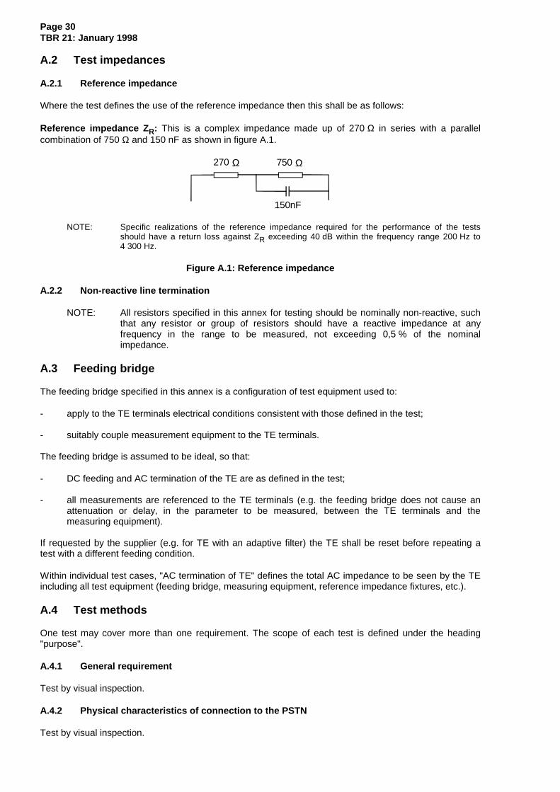
Where the test defines the use of the reference impedance then this shall be as follows:
Reference impedance Z R: This is a complex impedance made up of 270 Ω in series with a parallelcombination of 750 Ω and 150 nF as shown in figure A.1.
150nF
270 750 ΩΩ
NOTE: Specific realizations of the reference impedance required for the performance of the testsshould have a return loss against ZR exceeding 40 dB within the frequency range 200 Hz to4 300 Hz.
Figure A.1: Reference impedance
A.2.2 Non-reactive line termination
NOTE: All resistors specified in this annex for testing should be nominally non-reactive, suchthat any resistor or group of resistors should have a reactive impedance at anyfrequency in the range to be measured, not exceeding 0,5 % of the nominalimpedance.
A.3 Feeding bridge
The feeding bridge specified in this annex is a configuration of test equipment used to:
- apply to the TE terminals electrical conditions consistent with those defined in the test;
- suitably couple measurement equipment to the TE terminals.
The feeding bridge is assumed to be ideal, so that:
- DC feeding and AC termination of the TE are as defined in the test;
- all measurements are referenced to the TE terminals (e.g. the feeding bridge does not cause anattenuation or delay, in the parameter to be measured, between the TE terminals and themeasuring equipment).
If requested by the supplier (e.g. for TE with an adaptive filter) the TE shall be reset before repeating atest with a different feeding condition.
Within individual test cases, "AC termination of TE" defines the total AC impedance to be seen by the TEincluding all test equipment (feeding bridge, measuring equipment, reference impedance fixtures, etc.).
A.4 Test methods
One test may cover more than one requirement. The scope of each test is defined under the heading"purpose".
A.4.1 General requirement
Test by visual inspection.
A.4.2 Physical characteristics of connection to the PSTN
Test by visual inspection.
Page 31TBR 21: January 1998
A.4.3 Requirements in all conditions
A.4.3.1 Polarity
Where tests with both polarities are needed this is indicated in relevant clauses in this annex.
A.4.4 General requirements in quiescent state
A.4.4.1 DC Resistance
Requirement: Subclause 4.4.1.
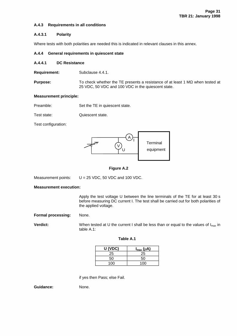
Purpose: To check whether the TE presents a resistance of at least 1 MΩ when tested at25 VDC, 50 VDC and 100 VDC in the quiescent state.
Measurement principle:
Preamble: Set the TE in quiescent state.
Test state: Quiescent state.
Test configuration:
U
Terminal
equipment
A
Figure A.2
Measurement points: U = 25 VDC, 50 VDC and 100 VDC.
Measurement execution:
Apply the test voltage U between the line terminals of the TE for at least 30 sbefore measuring DC current I. The test shall be carried out for both polarities ofthe applied voltage.
Formal processing: None.
Verdict: When tested at U the current I shall be less than or equal to the values of Imax intable A.1:
Table A.1
U (VDC) Imax (µA)25 2550 50100 100
if yes then Pass; else Fail.
Guidance: None.

Page 32TBR 21: January 1998
A.4.4.2 Characteristics of TE for ringing signals
A.4.4.2.1 Impedance
Requirement: Subclause 4.4.2.1.
Purpose: To determine whether the TE presents an impedance in the quiescent stateduring ringing within the specified range.
Measurement principle:
Preamble: Set the TE in quiescent state with any auto answering facility disabled.
Test state: Quiescent state.
Test configuration:
~TerminalequipmentU
I
TE
TE50VDC
V
A2050 Ω
Figure A.3
DC feeding arrangement: Feed Voltage = 50 V DC.
AC feeding arrangement: Sinusoidal source U0 25 Hz and 50 Hz, 30 V rms UTE measured across the TE.
Measurement points: Voltage UTE and current ITE measured for the frequencies of 25 Hz and 50 Hz.
Safety Warning : This test presents the potential for a shock hazard. Ensure that satisfactorysafety precautions are implemented to reduce the risk of electric shock.
Measurement execution:
Using the test configuration shown, apply the ringing signal continuously to theTE. Adjust the source voltage (U0) to set the voltage across the TE (UTE) to30 V rms. However, if UTE is less than 30 V rms for a source voltage of90 V rms then the source voltage is not increased further and the test is deemedcompleted. Otherwise, measure the current (ITE) flowing in the circuit.
Formal processing: The impedance of the TE during ringing can be calculated using the followingformula:
ZU
IRiTE
TE=
Verdict: If it is possible to apply 30 V rms at the TE terminals with a source voltage ofless than or equal to 90 V rms and if |ZRi| is equal to or greater than 4 kΩ thenPass; else Fail.
Guidance: True rms reading instruments should be used because voltages and currentsacross the TE may not be sinusoidal.

Page 33TBR 21: January 1998
A.4.4.2.2 Transient response
Requirement: Subclause 4.4.2.2.
Purpose: To check that the transient DC characteristics of the TE in quiescent statecomply with subclause 4.4.2.2.
Measurement principle:
Preamble: Set the TE in quiescent state with the line terminals shorted together.
Test state: Quiescent state. The TE shall have been in the quiescent state for not less than1 minute.
Test configuration:
Terminal
equipment
sA
200
60VDC
Ω
I
Figure A.4
DC feeding arrangement: Feed Voltage = 60 V DC.
Measurement points: Measure current 1 ms and 6 ms after the connection of the voltage source.
Measurement execution:
Connect the voltage source to the TE with the switch S and monitor the linecurrent.
Verdict: If the line current is less than or equal to 25 mA 1 ms after the connection andless than or equal to 10 mA 6 ms after the connection then Pass; else Fail.
Guidance: None.
A.4.4.2.3 DC current
Requirement: Subclause 4.4.2.3.
Purpose: To determine whether the DC component of the ringing current exceeds 0,6 mA.
Measurement principle:
Preamble: Set the TE in quiescent state with any auto answer facility disabled.
Test state: Quiescent state.

Page 34TBR 21: January 1998
Test configuration:
Terminalequipment
60VDC I
~
850
DC
ΩA
U0
Figure A.5
DC feeding arrangement: Feed Voltage = 60V DC.
AC feeding arrangement: Sinusoidal source U0 = 90 V rms, 25 Hz and 50 Hz .
Safety Warning : This test presents the potential for a shock hazard. Ensure that satisfactorysafety precautions are implemented to reduce the risk of electric shock.
Measurement execution:
Using the test configuration shown, apply the ringing signal. After 400 msmeasure the current IDC for one or more complete cycles of the DC voltage. Thetest shall be carried out for both polarities of the feeding voltage.
Formal processing: Calculate the average value (IDC).
Verdict: If the magnitude of IDC is less than or equal to 0,6 mA then Pass; else Fail.
Guidance: The sampling rate should be chosen to give an even integer of samples in onecycle.
A.4.4.3 Impedance unbalance about earth
Requirement: Subclause 4.4.3.
Purpose: To ensure that the impedance unbalance about earth expressed as LongitudinalConversion Loss meets the requirements.
Measurement principle:
Preamble: Set the TE in quiescent state.
Test state: Quiescent state.
Test configuration:
Terminalequipment
Earth point
U
U0~
FeedingbridgeRR t
Figure A.6
DC feeding arrangement: Feed voltage: 50 V. Feed resistance: 230 Ω. The test shall be made with bothpolarities.

Page 35TBR 21: January 1998
Measurement points: The resistors R shall be 300 Ω.
Uo shall be a sinusoidal signal with a constant voltage of 0,775 V rms throughoutthe specified frequency range (50 Hz to 3 400 Hz in 1/3th octave steps).Measurement of the transverse voltage Ut shall be performed with a suitablefrequency selective voltmeter.
Measurement execution:
Measure the voltage Ut across the specified frequency range. The test shall becarried out for both polarities of feeding.
Formal processing: The measured value of Ut is used to calculate the Longitudinal Conversion Lossby using the following equation at all the measurement points:
Longitudinal Conversion Loss = 20logU
U dB10
o
t
Verdict: If the Longitudinal Conversion Loss is greater than or equal to the specifiedlimits in table 2 and figure 2 then Pass; else Fail.
Guidance: The test sender output impedance should be less than 500 Ω.The voltmeter input impedance should be greater than 100 kΩ.
A.4.4.4 Resistance to earth
Requirement: Subclause 4.4.4.
Purpose: To check whether the TE complies with subclause 4.4.4 in the quiescent state.
Measurement principle:
Preamble: Set the TE in quiescent state.
Test state: Quiescent state.
Test configuration:
Terminal
equipment
I
Earth point
A
Feedingbridge
Figure A.7
DC feeding arrangement: Feed voltage: 50 V. Feed resistance: 230 Ω.
Measurement points: U = 100 volts DC.

Page 36TBR 21: January 1998
Measurement execution:
Apply test voltage U between one of the line terminals and the earth connectionpoint or points specified by the supplier's instructions for at least 30 s beforemeasuring current I. The test shall be carried out for both line terminals and forboth polarities of the applied test voltage and applied feeding voltage.
Formal processing: Resistance to earth (R) = U/I.
Verdict: If R is greater than or equal to 10 MΩ then Pass; else Fail.
Guidance: None.
A.4.5 Ringing signal detector sensitivity
Requirement: Subclause 4.5.
Purpose: To determine the ability of the TE to respond as stated to ringing signals asspecified by the supplier.
Measurement principle:
Preamble: Set the TE in quiescent state with answering facility enabled.
Test state: Quiescent state.
Test configuration:
U
Terminalequipment
50VDC
TE~V
850 Ω
Figure A.8
DC feeding arrangement: Feed Voltage = 50 V DC.
Measurement points: The ringing signal shall have a sinusoidal source of 25 Hz and 50 Hz and acadence of 1 s ON and 5 s OFF.
UTE = 30 V rms
Safety Warning: This test presents the potential for a shock hazard. Ensure that satisfactorysafety precautions are implemented to reduce the risk of electric shock.
Measurement execution:
Using the test configuration shown in figure A.8, apply, one at a time, each oneof the ringing signals described in "Measurement points" to the circuit todetermine whether they are detected by the TE as stated by the supplier.
Formal processing: None.
Verdict: If TE detects all the ringing signals above described in "Measurement points"then Pass; else Fail.
Guidance: For automatic answering TE, after the stimulation to cause the seizure, therequirement stated in subclause 4.6.2 and its associated test case apply.

Page 37TBR 21: January 1998
A.4.6 Transition from quiescent to loop state
A.4.6.1 Acceptance of breaks in the loop in a call attempt
Requirement: Subclause 4.6.1.
Purpose: To check that the DC characteristics of the TE during the transition fromquiescent to loop state comply with subclause 4.6.1.
Measurement principle:
Preamble: Set the TE in quiescent state.
Test state: In transition from quiescent to loop state.
Test configuration:
Terminal
equipment
sA
850
50VDC
Ω
Figure A.9
DC feeding arrangement: Feed voltage: 50 VDC.
Measurement points: as in test configuration.
Measurement execution:
Monitor the current across the TE line termination. Cause the TE to make atransition from the quiescent to the loop state. When the line feeding current hasfirst reached and remained at a value greater than 12,8 mA for:
test 1: 30 ms;
test 2: 500 ms.
interrupt the current for a period of 400 ms. Continue to monitor the current for aperiod of 100 ms after restoration.
Formal processing: If the current drops below 12,8 mA for more than one period of time, then sumall the periods to obtain the total time for comparison with the limit.
Verdict: If the line current has reached a value greater than 12,8 mA within 20 ms of therestoration AND if, during the period between 20 ms and 100 ms after therestoration, the current does not drop below 12,8 mA for more than 7 ms, thenPass; else Fail.
Guidance: None.
A.4.6.2 Loop current characteristics
Requirement: Subclause 4.6.2.
Purpose: To check that the current/time characteristics of the TE during the transitionfrom quiescent to loop state comply with subclause 4.6.2.

Page 38TBR 21: January 1998
Measurement principle:
Preamble: Set the TE in quiescent state for a time greater than 1 minute.
Test state: Cause the TE to make a transition to loop state.
Test configuration:
Terminal
equipment
A
50VDC
Rf
Figure A.10
DC feeding arrangement: Feed voltage: 50 VDC. Feed resistance Rf, each of the following: 150 kΩ,36 kΩ, 24 kΩ, 8 kΩ 3,2 kΩ, 230 Ω.
Measurement points: Feed resistances listed above in the DC feeding arrangement.
Measurement execution:
Before measuring for each resistance value, keep the TE in quiescent state for1 minute. In sequence, select a Rf resistance value according to the selectedfeeding resistance and then cause the TE to make a transition from thequiescent to the loop state.
Test 1: For Rf : 150 kΩ, 36 kΩ, 24 kΩ and 8 kΩ, monitor I for the period from t0to t2 as indicated in table 3 and figure 3.
Test 2: For Rf : 3,2 kΩ and 230 Ω, monitor I for the period from t0 to t3 asindicated in table 4 and figure 4.
Formal processing: For each feeding resistance, calculate the sum of the transient periods wherethe current I falls under the limit of figure 3 or figure 4 as relevant.
Verdict: If for test 1 the TE complies with the limits stated in table 3 and in figure 3 apartfrom transients whose aggregated period is less than 7 ms and if for test 2 theTE complies with the limits stated in table 4 and in figure 4 apart from transientswhose aggregated period is less than 7 ms then Pass; else Fail.
Guidance: None.
A.4.7 General loop state requirements
A.4.7.1 DC characteristics
Requirement: Subclause 4.7.1.
Purpose: To verify that the steady-state DC loop characteristics are within the limits givenin table 5, and shown in figure 5. The test only applies to TE which are capableof reaching the loop state.
Measurement principle:
Preamble: Set the TE in quiescent state.
Test state: Loop state.

Page 39TBR 21: January 1998
Test configuration:
Terminal
equipment
A
50VDC
RfU
V
Figure A.11
DC feeding arrangement: Feed voltage: 50 V. Feed resistance: each of the following: 230 Ω, 850 Ω,2 050 Ω, and 3 200 Ω. Polarity shall be switched between each feed resistance.
Measurement execution:
In sequence, select a feed resistance value according to the DC feedingarrangement and then cause the TE to enter the loop state after making surethat the TE has been held at least 1 minute in quiescent state. When theterminal has been in the loop state for at least 1,2 s, measure the DC currentdrawn by the TE and the DC voltage across the TE for each of the feedconditions. Allow sufficient settling time, to a maximum of 3 s, to ensure that themeasured value is stable to within ± 0,5 % for at least 0,2 s. Then repeat thesequence for other measurement points, repeating each time a transition fromquiescent state to loop state.
Formal processing: None.
Verdict: If the DC voltage/current characteristics are within the limits given in table 5, andshown in figure 5 then Pass; else Fail.
Guidance: Allowing "sufficient settling time" is useful to ensure test repeatability andreproducibility. Nevertheless if the stated stability cannot be found, the settlingtime shall be limited to 3 s. In this latter case a measurement accuracyimprovement may be obtained by averaging several measurement readingsmade during the settling time.
A.4.7.2 Impedance
Requirement: Subclause 4.7.2.
Purpose: To verify that the return loss of the input impedance (Zi) of the TE in relation tothe reference impedance ZR is within the limits specified below.
Measurement principle:
Preamble: Set the TE in loop state.
Test state: Loop state.
Test configuration:
Terminal
equipment
Feedingbridge
Measuringequipment RZ
Figure A.12
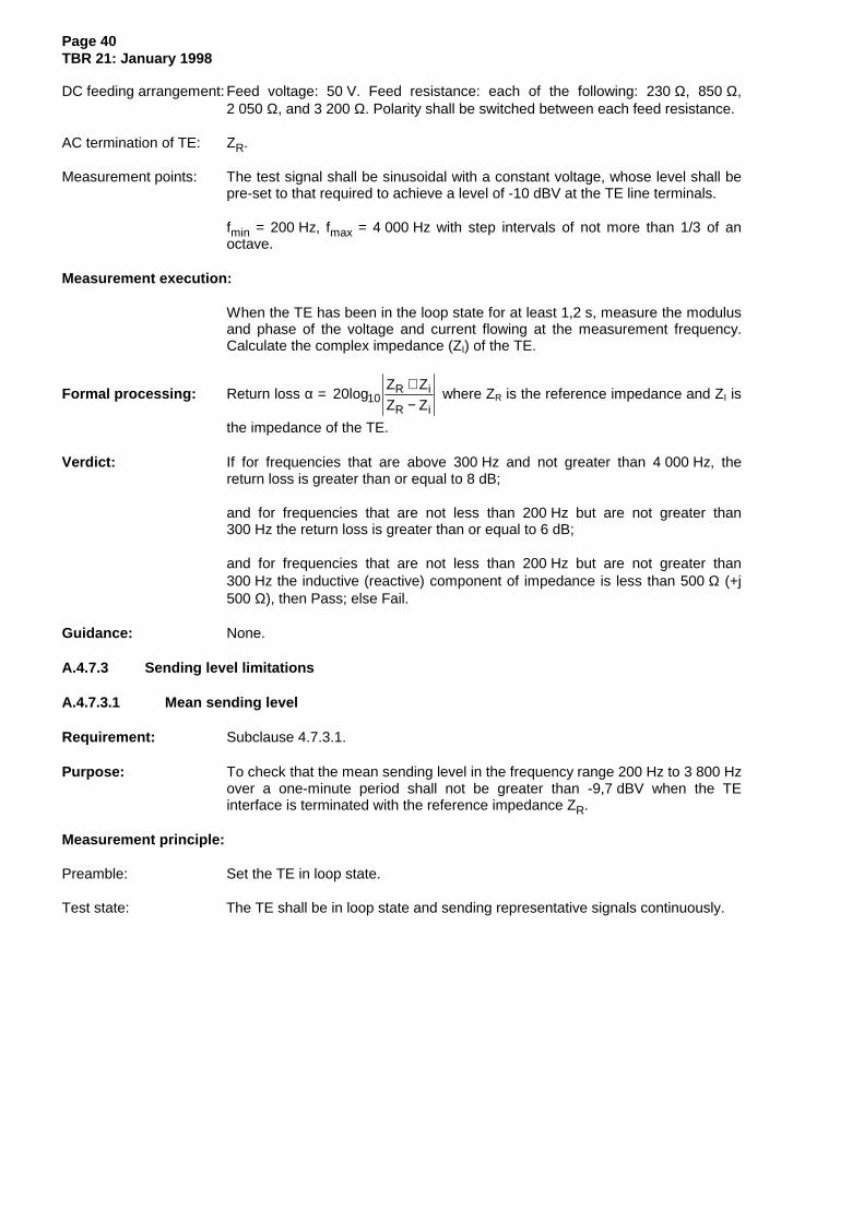
Page 40TBR 21: January 1998
DC feeding arrangement: Feed voltage: 50 V. Feed resistance: each of the following: 230 Ω, 850 Ω,2 050 Ω, and 3 200 Ω. Polarity shall be switched between each feed resistance.
AC termination of TE: ZR.
Measurement points: The test signal shall be sinusoidal with a constant voltage, whose level shall bepre-set to that required to achieve a level of -10 dBV at the TE line terminals.
fmin = 200 Hz, fmax = 4 000 Hz with step intervals of not more than 1/3 of anoctave.
Measurement execution:
When the TE has been in the loop state for at least 1,2 s, measure the modulusand phase of the voltage and current flowing at the measurement frequency.Calculate the complex impedance (ZI) of the TE.
Formal processing: Return loss α = 20logZ ZZ Z10
R i
R i
+−
where ZR is the reference impedance and ZI is
the impedance of the TE.
Verdict: If for frequencies that are above 300 Hz and not greater than 4 000 Hz, thereturn loss is greater than or equal to 8 dB;
and for frequencies that are not less than 200 Hz but are not greater than300 Hz the return loss is greater than or equal to 6 dB;
and for frequencies that are not less than 200 Hz but are not greater than300 Hz the inductive (reactive) component of impedance is less than 500 Ω (+j500 Ω), then Pass; else Fail.
Guidance: None.
A.4.7.3 Sending level limitations
A.4.7.3.1 Mean sending level
Requirement: Subclause 4.7.3.1.
Purpose: To check that the mean sending level in the frequency range 200 Hz to 3 800 Hzover a one-minute period shall not be greater than -9,7 dBV when the TEinterface is terminated with the reference impedance ZR.
Measurement principle:
Preamble: Set the TE in loop state.
Test state: The TE shall be in loop state and sending representative signals continuously.

Page 41TBR 21: January 1998
Test configuration:
Terminal
equipment
Feedingbridge
Measuringequipment RZ
Figure A.13
DC feeding arrangement: Feed voltage: 50 V. Feed resistance: each of the following: 230 Ω, and 3 200 Ω.Polarity shall be switched between each feed resistance.
AC termination of TE: ZR
Measurement points: The TE is exercised to send to line representative combinations of its declaredoutput capabilities.
Measurement execution:
The TE shall be set in loop state, transmitting representative signalscontinuously. The mean sending level in the frequency range 200 Hz to3 800 Hz transmitted across the termination points of the TE shall bedetermined over a one-minute period.
Formal processing: None.
Verdict: If the mean level over a one-minute period is less than or equal to -9,7 dBV thenPass; else Fail.
Guidance: TE with adjustable output level is set up in accordance with the supplier'sinstructions for intended use, or in the absence of instructions, is set to send atits maximum level. The TE is then operated in accordance with its intended use.For data equipment (e.g. modems), any output signal may be a test messageconsisting of a representative bit pattern or a scrambled signal. For answeringmachines or similar equipment where the output is derived from recordedspeech, any recorded signal shall have been prepared in accordance with thesupplier's instruction for intended use.
A.4.7.3.2 Instantaneous voltage
Requirement: Subclause 4.7.3.2.
Purpose: To check that the peak to peak voltage of the TE complies with subclause4.7.3.2.
Measurement principle:
Preamble: Set the TE in loop state.
Test state: The TE shall be in loop state and sending representative signals.

Page 42TBR 21: January 1998
Test configuration:
Terminal
equipment
Feedingbridge
Measuringequipment RZ
Figure A.14
DC feeding arrangement: Feed voltage: 50 V. Feed resistance: each of the following: 230 Ω, and 3 200 Ω.Polarity shall be switched between each feed resistance.
AC termination of TE: ZR.
Measurement points: The TE is exercised to send to the line:
- representative combinations of its declared output capabilities;- DTMF signals.
Measurement execution:
The TE shall be set in the loop state, transmitting representative signals. Thepeak to peak voltage transmitted across the termination points of the TE, shallbe measured.
Formal processing: None.
Verdict: If the peak to peak voltage is not higher than 5,0 V then Pass; else Fail.
Guidance: TE with adjustable output level is set up in accordance with supplier'sinstructions to send at its maximum intended level.
A.4.7.3.3 Sending level in a 10 Hz bandwidth
Requirement: Subclause 4.7.3.3.
Purpose: To check that the TE complies with subclause 4.7.3.3.
Measurement principle:
Preamble: Set the TE in loop state.
Test state: The TE shall be in loop state and sending representative signals continuously.
Test configuration:
Terminal
equipment
Feedingbridge
Measuringequipment RZ
Figure A.15
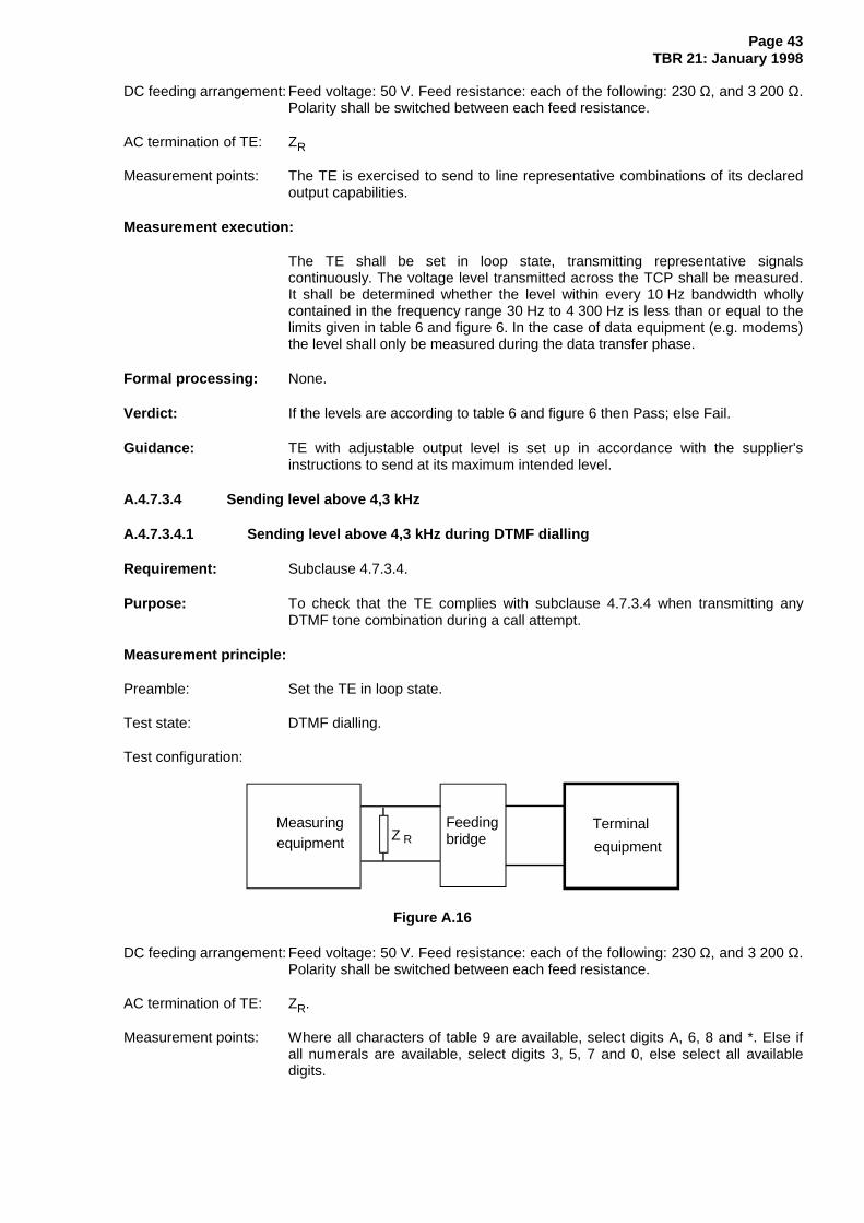
Page 43TBR 21: January 1998
DC feeding arrangement: Feed voltage: 50 V. Feed resistance: each of the following: 230 Ω, and 3 200 Ω.Polarity shall be switched between each feed resistance.
AC termination of TE: ZR
Measurement points: The TE is exercised to send to line representative combinations of its declaredoutput capabilities.
Measurement execution:
The TE shall be set in loop state, transmitting representative signalscontinuously. The voltage level transmitted across the TCP shall be measured.It shall be determined whether the level within every 10 Hz bandwidth whollycontained in the frequency range 30 Hz to 4 300 Hz is less than or equal to thelimits given in table 6 and figure 6. In the case of data equipment (e.g. modems)the level shall only be measured during the data transfer phase.
Formal processing: None.
Verdict: If the levels are according to table 6 and figure 6 then Pass; else Fail.
Guidance: TE with adjustable output level is set up in accordance with the supplier'sinstructions to send at its maximum intended level.
A.4.7.3.4 Sending level above 4,3 kHz
A.4.7.3.4.1 Sending level above 4,3 kHz during DTMF dialling
Requirement: Subclause 4.7.3.4.
Purpose: To check that the TE complies with subclause 4.7.3.4 when transmitting anyDTMF tone combination during a call attempt.
Measurement principle:
Preamble: Set the TE in loop state.
Test state: DTMF dialling.
Test configuration:
Terminal
equipment
Feedingbridge
Measuringequipment RZ
Figure A.16
DC feeding arrangement: Feed voltage: 50 V. Feed resistance: each of the following: 230 Ω, and 3 200 Ω.Polarity shall be switched between each feed resistance.
AC termination of TE: ZR.
Measurement points: Where all characters of table 9 are available, select digits A, 6, 8 and *. Else ifall numerals are available, select digits 3, 5, 7 and 0, else select all availabledigits.

Page 44TBR 21: January 1998
Measurement execution:
The TE shall be set in the loop state, transmitting DTMF characters to line.
Measurement shall be made during the tone duration as defined in subclause4.8.2.4 (minimum duration 65 ms).
It shall be determined whether all single frequency components individually havea sending level less than or equal to -35,7 dBV in the range 4,3 kHz to 20 kHzand -40,7 dBV in the range 20 kHz to 200 kHz.
Formal processing: None.
Verdict: If the voltage level of each single frequency component is less than or equal to-35,7 dBV in the range 4,3 kHz to 20 kHz and -40,7 dBV in the range 20 kHz to200 kHz then Pass; else Fail.
Guidance: All characteristics of the TE are captured for practical purposes when thediagonal in table 9 is used, going from the digit with the largest frequencydifference in its combination (highest/lowest frequency) up to the digit with thesmallest frequency difference.
A.4.7.3.4.2 Sending level above 4,3 kHz during communication
Requirement: Subclause 4.7.3.4.
Purpose: To check that the TE complies with subclause 4.7.3.4 in loop state.
Measurement principle:
Preamble: Set the TE in loop state.
Test state: The TE shall be in loop state and sending representative signals continuously.
Test configuration:
Terminal
equipment
Feedingbridge
Measuringequipment RZ
Figure A.17
DC feeding arrangement: Feed voltage: 50 V. Feed resistance: each of the following: 230 Ω, and 3 200 Ω.Polarity shall be switched between each feed resistance.
AC termination of TE: ZR.
Measurement points: The TE is exercised to send to line representative combinations of its declaredoutput capabilities.

Page 45TBR 21: January 1998
Measurement execution:
The TE is set in loop state, transmitting representative signals continuously. Thesending level across the termination points of the TE shall be measured. It isdetermined whether the level in a bandwidth defined in table 7, wholly containedin the frequency range 4,3 kHz to 200 kHz, is less than or equal to the limits oftable 7 and figure 7. Where these limits are exceeded it is determined whetherexceeding the limits is caused by tone signals having one or more singlefrequency component whose individual voltage level is less than or equal to-35,7 dBV in the range 4,3 kHz to 20 kHz and -40,7 dBV in the range 20 kHz to200 kHz.
Formal processing: None.
Verdict: If the sending level complies with table 7 and figure 7 then Pass.
If the only non-compliance with table 7 and figure 7 is due to a tone signal withone or more single frequency components whose individual levels are less thanor equal to -35,7 dBV in the range 4,3 kHz to 20 kHz and -40,7 dBV in the range20 kHz to 200 kHz then Pass; else, Fail.
Guidance: TE with adjustable output level is set up in accordance with supplier'sinstructions to send at its maximum level.
A.4.7.4 Impedance unbalance about earth
A.4.7.4.1 Longitudinal Conversion Loss
Requirement: Subclause 4.7.4.1.
Purpose: To ensure that the impedance unbalance about earth, expressed asLongitudinal Conversion Loss, meets the requirements.
Measurement principle:
Preamble: Set the TE in loop state.
Test state: Loop state.
Test configuration:
Terminalequipment
Earth point
U
U0~
FeedingbridgeRR t
Figure A.18
DC feeding arrangement: Feed voltage: 50 V. Feed resistance: each of the following: 230 Ω, 850 Ω,2 050 Ω, and 3 200 Ω. Polarity shall be switched between each feed resistance.

Page 46TBR 21: January 1998
Measurement points: The resistors R shall be 300 Ω.
Uo shall be a sinusoidal signal with a constant voltage of 0,775 V throughout thespecified frequency range (50 Hz to 3 800 Hz in 1/3th octave steps).Measurement of the transverse voltage Ut shall be performed with a suitablefrequency selective voltmeter.
Measurement execution:
Measure the transversal voltage Ut across the specified frequency range foreach of the feed conditions. Allow sufficient settling time at each feed conditionto ensure that the measured value is stable to within ± 0,5 % for at least 0,2 s.
Formal processing: The measured value of Ut is used to calculate the Longitudinal Conversion Lossby using the following equation:
Longitudinal Conversion Loss = 20logU
U dB10
o
t.
Verdict: If the Longitudinal Conversion Loss is greater than the specified limit in table 8and figure 8 then Pass; else Fail.
Guidance: The test sender output impedance should be less than 500 Ω. The voltmeterinput impedance should be greater than 100 kΩ.
A.4.7.4.2 Output Signal Balance
Requirement: Subclause 4.7.4.2.
Purpose: To ensure that the impedance unbalance about earth, expressed as outputsignal balance, meets the requirements.
Measurement principle:
Preamble: Set the TE in loop state.
Test state: Loop state.
Test configuration:
Terminal
equipment
U0
FeedingbridgeR R Ut
150 Ω
Earth point
Figure A.19
DC feeding arrangement: Feed voltage: 50 V. Feed resistance: each of the following: 230 Ω, 850 Ω,2 050 Ω, and 3 200 Ω. Polarity shall be switched between each feed resistance.
Measurement points: The resistors R shall be 300 Ω. Measurement of the voltages Uo and Ut shall beperformed with a suitable frequency selective voltmeter.

Page 47TBR 21: January 1998
Measurement execution:
The TE is set in the loop state transmitting representative signals to line.
Formal processing: The measured values of Uo and Ut are used to calculate the OSB by using thefollowing equation:
Output Signal Balance = 20 10logUU
dBt
o.
For frequencies at which Uo is less than -70 dBV the OSB is not calculated.
Verdict: If the OSB is greater than the specified limit in table 8 and figure 8 then Pass;else Fail. For frequencies at which Uo is less than -70 dBV there is no OSBrequirement.
Guidance: The voltmeter input impedance should be greater than 100 kΩ.
A.4.7.5 Resistance to earth
Requirement: Subclause 4.7.5.
Purpose: To check whether the TE complies with subclause 4.7.5 in the loop state.
Measurement principle:
Preamble: Set the TE in loop state.
Test state: Loop state.
Test configuration:
Terminal
equipment
I
Earth point
A
Feedingbridge
Figure A.20
DC feeding arrangement: Feed voltage: 50 V. Feed resistance: 230 Ω.
Measurement points: U = 100 VDC.
Measurement execution:
Apply test voltage U between one of the line terminals and the earth connectionpoint or points specified by the supplier's instructions for at least 30 s beforemeasuring current I. The test shall be carried out for both polarities of theapplied test voltage and applied feeding voltage.
Formal processing: Resistance to earth (R) = U/I.

Page 48TBR 21: January 1998
Verdict: If R is greater than or equal to 1 MΩ then Pass; else Fail.
Guidance: None.
A.4.8 Call attempt
A.4.8.1 Automatic dialling
A.4.8.1.1 Dialling without dial tone detection
Requirement: Subclause 4.8.1.1.
Purpose: To check that the TE starts dialling within the allowed period after seizure.
Measurement principle:
Preamble: Set the TE in quiescent state, tone-detector if any, disabled. If the pause beforedialling is adjustable by the user, set it in accordance with the supplier’sinstructions to the closest available value to the midpoint between 3 and 8 s. Iftwo values are equally close to the mid point, then use the lower value.
Test state: Automatic DTMF dialling.
Test configuration:
Terminal
equipment
Feedingbridge
Measuringequipment RZ
Figure A.21
DC feeding arrangement: Feed voltage: 50 V. Feed resistance: 850 Ω.
AC termination of TE: ZR.
Measurement execution:
The TE is set in the loop state, transmitting signalling characters to line. Thetime shall be measured from seizure up to the start of the first digit.
Formal processing: None.
Verdict: If the time delay is equal to or greater than 2,7 s and dialling has started within8 s then Pass; else Fail.
Guidance: None.
A.4.8.1.2 Dialling with dial tone detection
Requirement: Subclause 4.8.1.2.
Purposes: To check whether, after seizure, the TE starts dialling within the allowed periodafter the start of the dial tone.
Measurement principle:
Preamble: Set the TE in quiescent state with dial tone detector enabled.
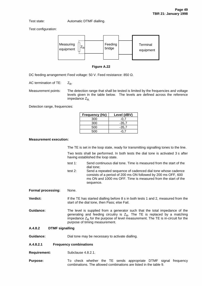
Page 49TBR 21: January 1998
Test state: Automatic DTMF dialling.
Test configuration:
Terminal
equipment
Feedingbridge
Measuringequipment RZ
Figure A.22
DC feeding arrangement: Feed voltage: 50 V. Feed resistance: 850 Ω.
AC termination of TE: ZR.
Measurement points: The detection range that shall be tested is limited by the frequencies and voltagelevels given in the table below. The levels are defined across the referenceimpedance ZR.
Detection range, frequencies:
Frequency (Hz) Level (dBV)300 -0,7300 -35,7500 -35,7500 -0,7
Measurement execution:
The TE is set in the loop state, ready for transmitting signalling tones to the line.
Two tests shall be performed. In both tests the dial tone is activated 3 s afterhaving established the loop state.
test 1: Send continuous dial tone. Time is measured from the start of the dial tone;
test 2: Send a repeated sequence of cadenced dial tone whose cadence consists of a period of 200 ms ON followed by 200 ms OFF, 600 ms ON and 1000 ms OFF. Time is measured from the start of the sequence.
Formal processing: None.
Verdict: If the TE has started dialling before 8 s in both tests 1 and 2, measured from thestart of the dial tone, then Pass; else Fail.
Guidance: The level is supplied from a generator such that the total impedance of thegenerating and feeding circuitry is ZR. The TE is replaced by a matchingimpedance ZR for the purpose of level measurement. The TE is in-circuit for thepurpose of timing measurement.
A.4.8.2 DTMF signalling
Guidance: Dial tone may be necessary to activate dialling.
A.4.8.2.1 Frequency combinations
Requirement: Subclause 4.8.2.1.
Purpose: To check whether the TE sends appropriate DTMF signal frequencycombinations. The allowed combinations are listed in the table 9.
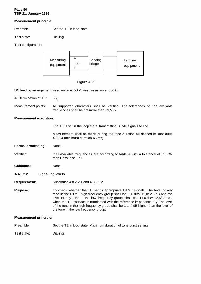
Page 50TBR 21: January 1998
Measurement principle:
Preamble: Set the TE in loop state
Test state: Dialling.
Test configuration:
Terminal
equipment
Feedingbridge
Measuringequipment RZ
Figure A.23
DC feeding arrangement: Feed voltage: 50 V. Feed resistance: 850 Ω.
AC termination of TE: ZR.
Measurement points: All supported characters shall be verified. The tolerances on the availablefrequencies shall be not more than ±1,5 %.
Measurement execution:
The TE is set in the loop state, transmitting DTMF signals to line.
Measurement shall be made during the tone duration as defined in subclause4.8.2.4 (minimum duration 65 ms).
Formal processing: None.
Verdict: If all available frequencies are according to table 9, with a tolerance of ±1,5 %,then Pass; else Fail.
Guidance: None.
A.4.8.2.2 Signalling levels
Requirement: Subclause 4.8.2.2.1 and 4.8.2.2.2
Purpose: To check whether the TE sends appropriate DTMF signals. The level of anytone in the DTMF high frequency group shall be -9,0 dBV +2,0/-2,5 dB and thelevel of any tone in the low frequency group shall be -11,0 dBV +2,5/-2,0 dBwhen the TE interface is terminated with the reference impedance ZR. The levelof the tone in the high frequency group shall be 1 to 4 dB higher than the level ofthe tone in the low frequency group.
Measurement principle:
Preamble Set the TE in loop state. Maximum duration of tone burst setting.
Test state: Dialling.
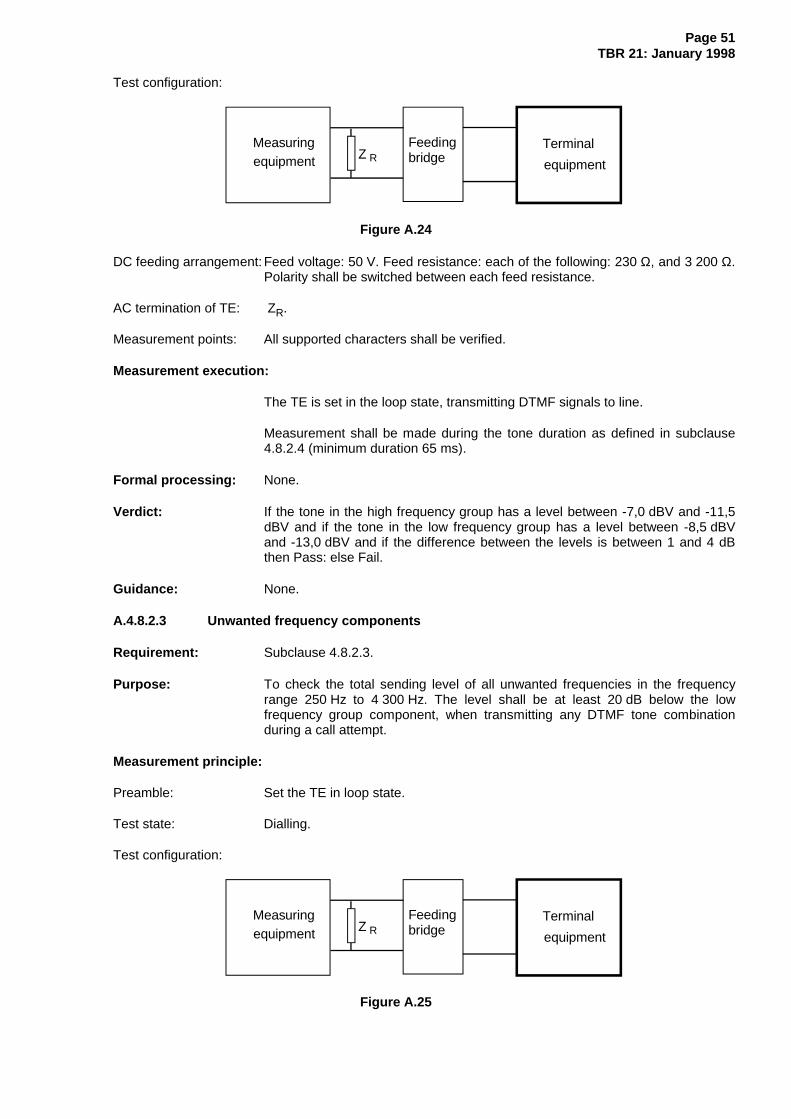
Page 51TBR 21: January 1998
Test configuration:
Terminal
equipment
Feedingbridge
Measuringequipment RZ
Figure A.24
DC feeding arrangement: Feed voltage: 50 V. Feed resistance: each of the following: 230 Ω, and 3 200 Ω.Polarity shall be switched between each feed resistance.
AC termination of TE: ZR.
Measurement points: All supported characters shall be verified.
Measurement execution:
The TE is set in the loop state, transmitting DTMF signals to line.
Measurement shall be made during the tone duration as defined in subclause4.8.2.4 (minimum duration 65 ms).
Formal processing: None.
Verdict: If the tone in the high frequency group has a level between -7,0 dBV and -11,5dBV and if the tone in the low frequency group has a level between -8,5 dBVand -13,0 dBV and if the difference between the levels is between 1 and 4 dBthen Pass: else Fail.
Guidance: None.
A.4.8.2.3 Unwanted frequency components
Requirement: Subclause 4.8.2.3.
Purpose: To check the total sending level of all unwanted frequencies in the frequencyrange 250 Hz to 4 300 Hz. The level shall be at least 20 dB below the lowfrequency group component, when transmitting any DTMF tone combinationduring a call attempt.
Measurement principle:
Preamble: Set the TE in loop state.
Test state: Dialling.
Test configuration:
Terminal
equipment
Feedingbridge
Measuringequipment RZ
Figure A.25

Page 52TBR 21: January 1998
DC feeding arrangement: Feed voltage: 50 V. Feed resistance: each of the following: 230 Ω, and 3 200 Ω.Polarity shall be switched between each feed resistance.
AC termination of TE: ZR.
Measurement points: Where all characters of table 9 are available, select digits A, 6, 8 and *. Else ifall numerals are available, select digits 3, 5, 7 and 0, else select all availabledigits.
Measurement execution:
The TE is set in the loop state, transmitting DTMF characters to the line.
Measurement in Volts shall be made during the sending period as defined insubclause 4.8.2.4 (minimum duration 65 ms).
Formal processing: Integration of all signal levels is divided in 3 parts:
- from 250 Hz up to the lower DTMF component;- from the lower DTMF component up to the higher DTMF component;- from the higher DTMF component up to 4 300 Hz.
Summation of all three parts gives the total unwanted sending level result.Frequencies up to 50 Hz on either side of the DTMF components shall beexcluded from the summation. This result is compared with the level of the lowerDTMF component.
Verdict: If the total unwanted signal level is at least 20 dB below the level of the lowerDTMF component for all available digits then Pass; else Fail.
Guidance The total unwanted sending level is calculated from the following formula:
Σ = + +a b c2 2 2
A.4.8.2.4 Tone duration
Requirement: Subclause 4.8.2.4.
Purpose: To check whether the TE sends DTMF signals of the appropriate duration. Thisrequirement applies only to a TE with an automatic dialling function. It applieswhen the TE is in automatic dialling mode.
The TE shall provide a setting whereby the duration of any individual DTMF tonecombination shall be at least 65 ms measured from the time when the tone levelhas reached 90 % of its steady-state value (without interruption), until it hasdropped to 90 % of its steady-state value.
Measurement principle:
Preamble: Set the TE in loop state.
Test state: Automatic dialling. Tone signal duration according to supplier's instructions.

Page 53TBR 21: January 1998
Test configuration:
Terminal
equipment
Feedingbridge
Measuringequipment RZ
Figure A.26
DC feeding arrangement: Feed voltage: 50 V. Feed resistance: 850 Ω.
AC termination of TE: ZR.
Measurement points: Where all characters of table 9 are available, select digits A, 6, 8 and *. Else ifall numerals are available, select digits 3, 5, 7 and 0, else select all availabledigits.
Measurement execution:
Set tone signalling duration according to supplier's instructions.
The TE is set in the loop state, transmitting DTMF signals to the line. Capturethe waveform of the DTMF signal.
Formal processing: In this formal processing, three waveforms derived from the measuredwaveform are used. These are referred to as waveforms A, B and C.
Determine waveform A such that at any time the instantaneous value ofwaveform A is equal to the absolute value of difference between the value of themeasured waveform at that time and the mean value of the measured waveformover a period of 10 ms centred on that time.
Determine waveform B such that at any time its value is the greater of the linearinterpolation of the maxima of waveform A, and waveform A.
Determine waveform C such that at any time its value is the greater of the linearinterpolation of the maxima of waveform B, and waveform B.
Determine the reference level such that it is 90% of the highest level whichwaveform C exceeds for 20 ms during the burst.
The duration of the burst is the duration of the greatest period of time for whichwaveform C exceeds the reference level.
Verdict: If all bursts have a duration greater than or equal to 70 ms then Pass. If anyburst has a duration of less than 60 ms then Fail;
The test shall be repeated ten times for any burst for which the duration isbetween 60 and 70 ms and the mean duration calculated. If the mean durationfor all such bursts is greater than or equal to 65 ms then Pass; else Fail.
Guidance: The repeatability of this test is intrinsically poor because the measured durationof the burst depends on the phase relationship of the tones. Thereforeaveraging is needed for borderline cases.
The relationship between the measured waveform and waveforms A, B and C isshown in figure A.27.

Page 54TBR 21: January 1998
-1
-0.8
-0.6
-0.4
-0.2
0
0.2
0.4
0.6
0.8
1
5.0 10.0 12.0
Measured
Wave A
Wave B
Reference level
Wave C
Figure A.27
A.4.8.2.5 Pause duration
Requirement: Subclause 4.8.2.5.
Purpose: To check whether the TE sends DTMF signals with the appropriate pauses. Thisrequirement applies only to a TE with an automatic dialling function.
The TE shall provide a setting whereby the duration of the pause between theDTMF tone combinations shall be at least 65 ms. Time is measured from themoment when the tone has dropped to 10 % of its steady-state value, until it hasrisen to 10 % of its steady-state value.
Measurement principle:
Preamble: Set the TE in loop state.
Test state: Automatic dialling.
Test configuration:
Terminal
equipment
Feedingbridge
Measuringequipment RZ
Figure A.28
DC feeding arrangement: Feed voltage: 50 V. Feed resistance: 850 Ω.
AC termination of TE: ZR.
Measurement points: Where all characters of table 9 are available, select digits A, 6, 8 and *. Else ifall numerals are available, select digits 3, 5, 7 and 0, else select all availabledigits.
Measurement execution:
The TE is set in the loop condition, transmitting DTMF signals to line. Set pauseduration in accordance with the supplier's instructions. Capture the waveform ofthe sequence of bursts.

Page 55TBR 21: January 1998
Formal processing: In this formal processing, a number of waveforms derived from the measuredwaveform are used. These shall be calculated independently for each burstThese are referred to as waveforms A, B, C etc.
Determine waveform A such that at any time the instantaneous value ofwaveform A is equal to the absolute value of difference between the value of themeasured waveform at that time and the mean value of the measured waveformover a period of 10 ms centred on that time.
Determine waveform B such that at any time its value is the greater of the linearinterpolation of the maxima of waveform A, and waveform A.
Determine waveform C such that at any time its value is the greater of the linearinterpolation of the maxima of waveform B, and waveform B.
Determine the reference level such that it is 10% of the highest level whichwaveform C exceeds for 20 ms during the burst.
The pause between two bursts is the time between the last instant thatwaveform C is greater than the reference level for the first burst and the firstinstant that waveform C is greater than the reference level for the second burst.
Verdict: If all pauses have a duration greater than or equal to 70 ms then Pass;
If any pause has a duration of less than 60 ms then Fail;
If any pause has a duration of between 60 ms and 70 ms then the test shall berepeated 10 times, and the mean duration of the pause between each of thepairs on characters calculated. If each mean duration is greater than 65 ms thenPass; otherwise Fail.
Guidance: The repeatability of this test is intrinsically poor because the measured durationof the burst depends on the phase relationship of the tones. Thereforeaveraging is needed for borderline cases.
A.4.8.3 Automatically repeated call attempts
Requirement: Subclause 4.8.3.
Purpose: To check that the TE complies with subclause 4.8.3.
Measurement principle:
Preamble: Set TE for automatic repeat call attempts to the same number. Set number ofrepeat call attempts to the maximum. Put TE in quiescent state.
Test state: Alternates between DTMF dialling, loop state and quiescent state.
Test configuration:
Terminal
equipment
Testequipment
FeedingbridgeRZ
Figure A.29
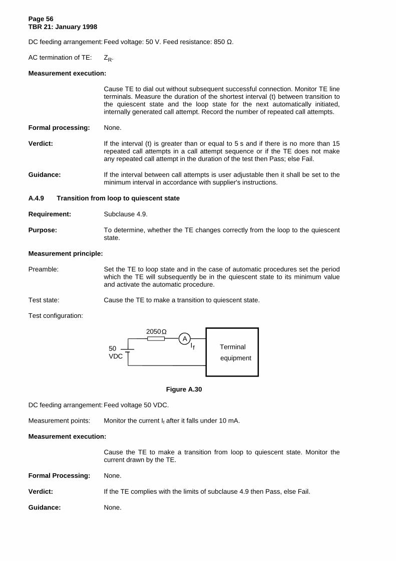
Page 56TBR 21: January 1998
DC feeding arrangement: Feed voltage: 50 V. Feed resistance: 850 Ω.
AC termination of TE: ZR.
Measurement execution:
Cause TE to dial out without subsequent successful connection. Monitor TE lineterminals. Measure the duration of the shortest interval (t) between transition tothe quiescent state and the loop state for the next automatically initiated,internally generated call attempt. Record the number of repeated call attempts.
Formal processing: None.
Verdict: If the interval (t) is greater than or equal to 5 s and if there is no more than 15repeated call attempts in a call attempt sequence or if the TE does not makeany repeated call attempt in the duration of the test then Pass; else Fail.
Guidance: If the interval between call attempts is user adjustable then it shall be set to theminimum interval in accordance with supplier's instructions.
A.4.9 Transition from loop to quiescent state
Requirement: Subclause 4.9.
Purpose: To determine, whether the TE changes correctly from the loop to the quiescentstate.
Measurement principle:
Preamble: Set the TE to loop state and in the case of automatic procedures set the periodwhich the TE will subsequently be in the quiescent state to its minimum valueand activate the automatic procedure.
Test state: Cause the TE to make a transition to quiescent state.
Test configuration:
Terminal
equipment
A
50VDC
2050
f
Ω
Figure A.30
DC feeding arrangement: Feed voltage 50 VDC.
Measurement points: Monitor the current If after it falls under 10 mA.
Measurement execution:
Cause the TE to make a transition from loop to quiescent state. Monitor thecurrent drawn by the TE.
Formal Processing: None.
Verdict: If the TE complies with the limits of subclause 4.9 then Pass, else Fail.
Guidance: None.

Page 57TBR 21: January 1998
Annex B (normative): TBR Requirements Table (TBR-RT)
Copyright release for TBR-RT proformas
Users of this TBR may freely reproduce annex B which contains this TBR-RT proforma so that it may beused for its intended purpose. Users may further publish the completed TBR-RT.
B.1 Guidance for completion of the TBR-RT
B.1.1 Condition table
For the requirements, there is a table of condition questions.
The Reference column contains references in the form C.x where:
- C: means Condition;
- x: uniquely identifies the element of the table.
The Condition column contains a question, the answer to which determines whether the correspondingrequirement(s) in the Requirements Table shall be mandatory.
The Status column identifies whether a "Yes" or "No" answer causes relevant requirements to bemandatory for the TE. The following codes are used:
- M: means that the relevant requirements are mandatory;
- N: means that the relevant requirements are not applicable.
The Support column is blank for the user to complete.
B.1.2 Requirements table
The Number column provides an unique identifier to each requirement.
The Reference column lists the subclause reference in the TBR where the requirement may be found.
The TBR Requirement column gives the clause title of the relevant clause, supplemented by anyadditional information necessary to identify the requirement.
The Status column contains one of the following items:
- M: means that the requirement is mandatory;
- C.x: means that the requirement is mandatory if the relevant condition is met.
In some cases, two or more Conditions are included in the status column. The requirement shall bemandatory if the Boolean combination of them is true.
The Support column is blank for the user to complete.

Page 58TBR 21: January 1998
Table B.1: Condition table
Reference Condition Status Support(Y/N)
Comment
C.1. Is the TE controlled by an externaldevice for the origination and/or thereception of a call?
If YES then Melse N
C.2. Is the TE intended to have aconnection to earth?
If YES then Melse N
C.3. Is the TE intended to be in loop state? If YES then Melse N
C.4. Is the TE intended for call answer? If YES then Melse N
C.5. Is the TE intended for call set-up? If YES then Melse N
C.6. Is the TE intended for dialling withDTMF?
If YES then Melse N
C.7. Is the TE intended for automaticdialling without dial tone detection?
If YES then Melse N
C.8. Is the TE intended for automaticdialling with dial tone detection?
If YES then Melse N
C.9. Is the TE intended for use in receivingmode?
If YES then Melse N
C.10. Is the TE intended for use intransmitting mode?
If YES then Melse N
C.11. Is the TE intended for makinginternally generated automaticallyrepeated call attempts?
If YES then Melse N
C.12. Is the TE intended for automaticallycontrolled signalling tone duration?
If YES then Melse N
C.13. Is the TE intended for automaticallycontrolled signalling pause duration?
If YES then Melse N

Page 59TBR 21: January 1998
Table B.2: Requirements table
No. Reference TBR Requirement Status Support(Y/N)
R.1. 4.1 General requirement C.1 R.2. 4.2 Physical characteristics of connection to the
PSTN M
R.3. 4.3.1 Polarity M R.4. 4.4.1 DC resistance M R.5. 4.4.2.1 Impedance M R.6. 4.4.2.2 Transient response M R.7. 4.4.2.3 DC-current M R.8. 4.4.3 Impedance unbalance about earth C.2 R.9. 4.4.4 Resistance to earth C.2 R.10. 4.5 Ringing signal detector sensitivity C.4 R.11. 4.6.1 Acceptance of breaks in the loop in a call
attempt C.5
R.12. 4.6.2 Loop current characteristics C.3 R.13. 4.7.1 DC characteristics C.3 R.14. 4.7.2 Impedance C.3 R.15. 4.7.3.1 Mean sending level C.3 R.16. 4.7.3.2 Instantaneous voltage C.3 R.17. 4.7.3.3 Sending level in a 10 Hz bandwidth C.3 R.18. 4.7.3.4 Sending level above 4,3 kHz C.3 R.19. 4.7.4.1 Longitudinal Conversion Loss C.2 and C.3 and C.9 R.20. 4.7.4.2 Output Signal Balance C.2 and C.3 and
C.10
R.21. 4.7.5 Resistance to earth C.2 and (C.4 or C.5) R.22. 4.8.1.1 Dialling without dial tone detection C.7 R.23. 4.8.1.2 Dialling with dial tone detection C.8 R.24. 4.8.2.1 Frequency combinations C.6 R.25. 4.8.2.2 1 Absolute levels C.6 R.26. 4.8.2.2.2 Level difference C.6 R.27. 4.8.2.3 Unwanted frequency components C.6 R.28. 4.8.2.4 Tone duration C.6 and C.12 R.29. 4.8.2.5 Pause duration C.6 and C.13 R.30. 4.8.3 Automatically repeated call attempts C.11 R.31. 4.9 Transition from loop to quiescent state C.3
Page 60TBR 21: January 1998
Annex C (informative): Bibliography
- 73/23/EEC: "Council Directive of 19 February 1973 on the harmonisation of the laws of the MemberStates relating to electrical equipment designed for use within certain voltage limits". The LowVoltage Directive (LVD). (OJ L77 26.03.73).
- 89/336/EEC: "Council Directive of 3 May 1989 on the approximation of the laws of the MemberStates relating to electromagnetic compatibility". The EMC Directive. (OJ L139 23.05.89).
- 91/263/EEC: "Council Directive of 29 April 1991 on the approximation of the laws of the MemberStates concerning telecommunications terminal equipment, including the mutual recognition of theirconformity". The TTE Directive. (OJ L128 23.05.91).
- EG 201 120: "Public Switched Telephone Network (PSTN); Method of rating terminal equipment sothat it can be connected in series and/or in parallel to a Network Termination Point (NTP)".
- EG 201 121: "A guide to the application of TBR 21".

Page 61TBR 21: January 1998
History
Document history
July 1995 Public Enquiry PE 87: 1995-07-10 to 1995-11-03
June 1996 Vote V 105: 1996-06-10 to 1996-08-16
October 1997 Second Vote V 9750: 1997-10-14 to 1997-12-12
January 1998 First Edition
ISBN 2-7437-1923-0Dépôt légal : Janvier 1998