task 5: layered formations workshop littleton, co april 25 and 26, 2000
TRANSCRIPT

Task 5: Layered Formations Workshop
Littleton, COApril 25 and 26, 2000
ObjectivesReview entry effects in layered media,
during PWRI, due to formation property variation, such as permeability-dependent plugging.
Evaluation of the role of layering on fracturing efficiency and propagation.
Containment concepts need to be evaluated.
Both matrix and fracturing situations need to be considered.
Issue 1: Crossflow "Crossflow is a big issue for MOC. It is important to
carefully define the crossflow environment that you are considering."
There is wellbore crossflow (Heidrun). There is near-wellbore crossflow (close to or
immediately behind pipe). There are consequences for injecting and for ultimate recovery by misdirecting flow.
There is far-wellbore crossflow, occurring deeper in the reservoir. Injectivity and ultimate recovery should not be divorced.
Different wellbore scenarios and completions methods that affect/control/improve recovery.
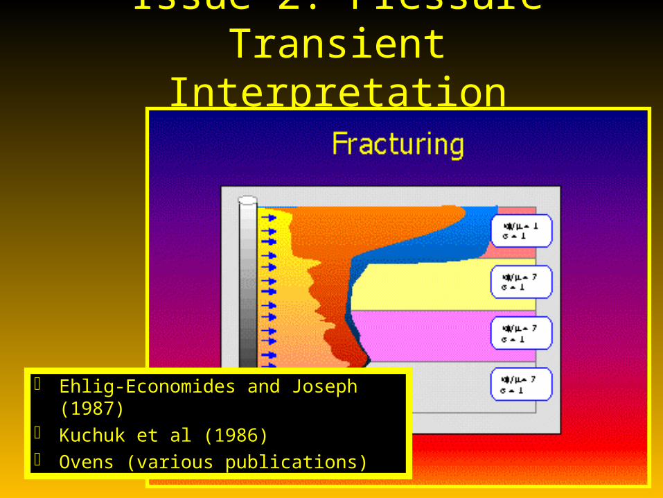
Issue 2: Pressure Transient Interpretation
Ehlig-Economides and Joseph (1987) Kuchuk et al (1986) Ovens (various publications)

Issue 3: Field ProceduresSpeculated that behavior during produced
water injection could be used as a conformance diagnostic.
"How do you control the well during its life?" Part of this relates to starting the operations out correctly!
"Are there situations where mechanical differences between formations can be overcome without using mechanical means for isolation? If so, how are these differences overcome?"
Issue 3a: Control Methods
Thermal pre-conditioningFormation pressure pre-conditioningTortuosityPerforating: BLANKET PERFORATING
SHOULD NOT BE USEDPerforating: DEMONSTRATED THE
IMPORTANCE OF CLEANING UP PERFORATIONS.
Perforating: Balance?

Issue 3b: Control MethodsA methodology for a formation breakdown was presented. • Cleaning perforations with backflow. The correct
perforation strategy was indicated to be important, as well as drilling.
• Inject at a rate for zero skin at fracturing pressure. The well will thermally fracture but you are still injecting below frac gradient.
• Inject at a constant rate at the uncooled fracturing pressure. If you do not know what this rate is, you need to do a SRT.
• Preferentially grow a fracture in one area without pressure being high enough to initiate fracturing elsewhere.
Issue 3c: Control Methods• Sometimes mechanical
methods may be only option.• Thermal fracturing.• Hybrid methods.• For A High Angle Well, There Is
A Minimum Rate For Cooldown And A Maximum Rate To Avoid All Of The Fluid From Going Into One Fracture.
• Seawater flushes• Low-cost smart wells

Issue 3d: Control Methods• "TO SEAL A HYDRAULIC FRACTURE IT IS NECESSARY TO
PUT IN GEL AND TO FOLLOW THIS WITH SOMETHING TO PLUG THE PERFORATIONS (for example, CaCO3).”
• Bacteria (membrane technology).• Cases shown where THERMAL FRACTURING IMPROVED
THE INJECTION PROFILE.• Nonconventional fracturing• Dual strings, nulilaterals, individual wells, wandering
wells• Sweep the high permeability and then flood it to
pressurize the low permeability zone• Multiple injection fluids

Issue 4: Prediction• Methods for predicting and inhibiting height
growth
• GOHFER• Warmback• Other Monitoring
)OIW,TSS,k(f75.0h
rln
PP
75.0r
rln
PP
2.141
khkQ
e
ri
w
e
rfrwi

Issue 4b: Prediction• Matrix flow in n
layers
• Wellbore Crossflow• Compartmentalization

Issue 4c: Prediction
Where do the solids go???What zones are most damaged?
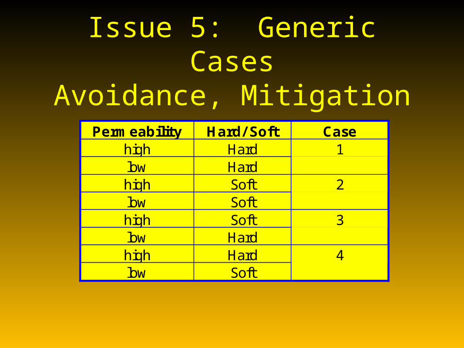
Issue 5: Generic CasesAvoidance, Mitigation
Permeability Hard/ Soft Casehigh Hardlow Hard
1
high Softlow Soft
2
high Softlow Hard
3
high Hardlow Soft
4

Action Items1. Summary of injection plugging relationships
(lessons learned and experience factor).2. Experience within the four generic layered
formation cases, including the type(s) of completions and fluids considered or used.
3. Discussion documents from this workshop. 4. Within the data that are available,
summarize what the data shows. Is there data that can be used that, for example, shows that water quality influences entry?
5. Revise the matrix model and circulate.6. Crossflow models as a diagnostic for
compartmentalization. 7. PEA-23 - Revisit the laboratory data
regarding where the solids go.

Task 1: Monitoring Workshop
April 27 and 28, 2000
Objectives• Monitoring and diagnostic methods for injectors
have not developed at the same rate as for producers. One reason is that hydraulic fracture closure during testing can complicate interpretation.
• PREDICTION. Just how good are available models. There are a number of codes around. It is important to identify the processes that need to be legitimately included in these predictive models.
• In addition to the modeling audit, an inventory of monitoring methods, citing limitations and applications, was requested.
Objectives• Procedures for fracture injector interpretation.
Falloff testing was indicated to be not completely accurate (closure during testing). What are the preferred test protocols and what data are required. Best Practices is a major goal - e.g. describe procedures for a multi-rate PLT followed by a falloff.
• What are the gaps in the methodologies and how can you optimize cost?
• Environmental issues - zero emission well testing.

Fractured Injector Well Test Gap Analysis
1. Inadequate representation of dynamic fractures, during falloff.
2. Single zone and single frac.3. Single frac and multi-layered (height/length
recession).4. Single zone and multiple fractures (co-located or
displaced).5. Multiple zone and multiple fractures.6. Pressure-dependent permeability.7. Radial and linear composite reservoir interpretation
when there is a fracture present.

Models
• What is it that really needs to be included in models, particularly in terms of storage?
• What steps are required to improve techniques and tools for measurement, surveillance and prediction?
• Are there improved methods for evaluating multilayered reservoirs? E.g. flow profile along with falloff. Need to do measurements in individual layers.
Models
• Fractured Injector Well Tests: What is the right protocol? For example, if you shut-in and do the SRT, it may be different than if you are injecting.
• A list of what should be done was requested.
• People should look in their own companies for forgotten/obsolete well test software that may be of value.

Models
• There is nothing? specifically available for falloff test analysis in fractured injectors.
• It was indicated that there was no commercial code available for it.
• Raise it at the next steering committee meeting and retain a third party to evaluate this. This is an urgent action item.
Fractured Injector Well Test Gap Analysis
Action Items
1. Allocation of JV funds for external party, if necessary.
2. Survey operators for methods being used and data.

Methods (Microseismic)• Shear versus hydraulic fractures• Permeability enhancement
ShMax
ShMax
Wate r Injection
Pre fe rred F looding Direction
Fractures a ligned para lle l to Sh Max open, inc reasing conduc tivity
in-s itu fa ults and fractures

Methods (Microseismic)• Depths of interest?• The signatures, to tell you more about what the signals mean
(origin)?• What have people tried to do for reprocessing microseismic
data to highlight events localized to the fracture?• Gas versus oil reservoirs• What are the current limitations. • “indicated that if the Sponsors see a need for this technology
to mature, maybe able the JIV should give direction to appropriate organizations.”
• MAJOR FOCUS ON WATERFLOODS.• Tomographic applications.

Methods (Tiltmeter)
• Key Restriction of Current Technology is Application in High Angle and Horizontal Well
• Using the technology in the same well in deviated and horizontal situations. Deviation and coupling with the formation are relevant and it would be reasonable to encourage the industry to accelerate current methods for doing this.
• Sponsors requested a review of what is currently the status of same-well tiltmeter usage.
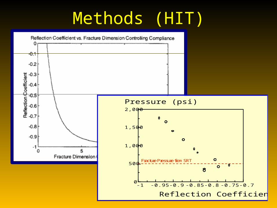
Methods (HIT)
-1 -0.95 -0.9 -0.85 -0.8 -0.75 -0.70
500
1,000
1,500
2,000
Reflection Coefficient
Pressure (psi)
Fracture Pressure from SRT
Methods (HIT)
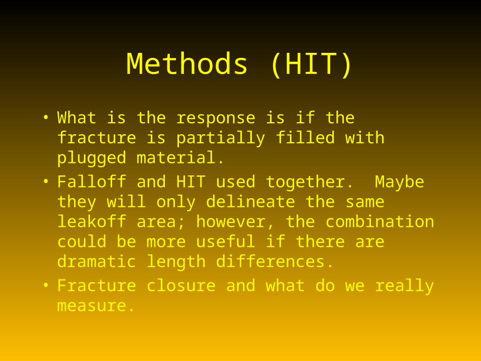
• What is the response is if the fracture is partially filled with plugged material.
• Falloff and HIT used together. Maybe they will only delineate the same leakoff area; however, the combination could be more useful if there are dramatic length differences.
• Fracture closure and what do we really measure.
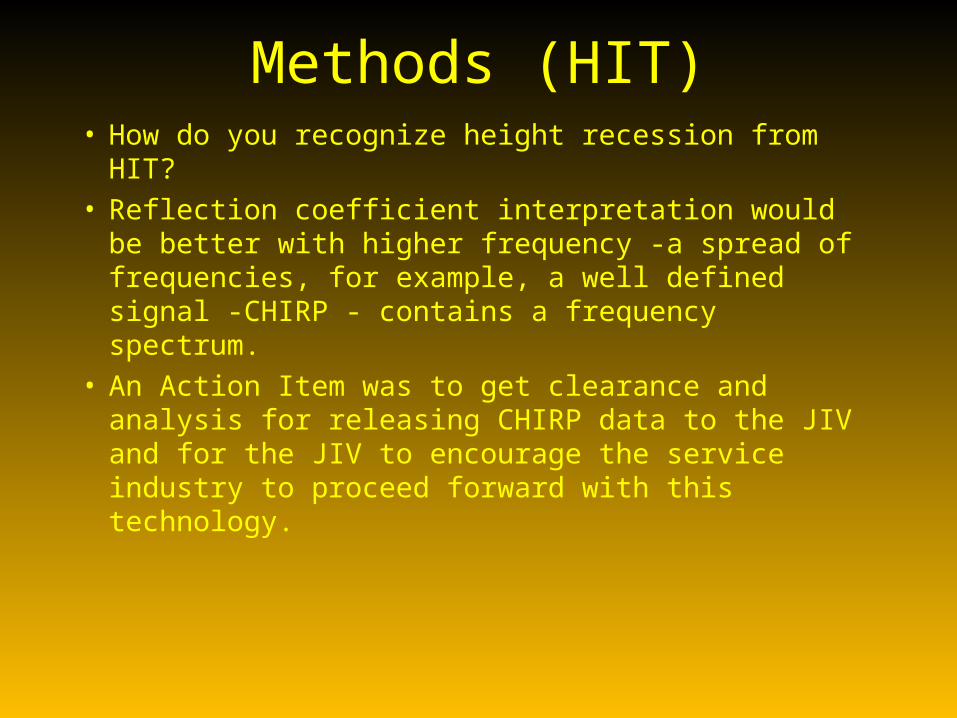
Methods (HIT)• How do you recognize height recession from
HIT? • Reflection coefficient interpretation would be
better with higher frequency -a spread of frequencies, for example, a well defined signal -CHIRP - contains a frequency spectrum.
• An Action Item was to get clearance and analysis for releasing CHIRP data to the JIV and for the JIV to encourage the service industry to proceed forward with this technology.
Predictive Methods
• New directions• Modified commercial reservoir
simulators• Disposal Domain Concept

Action Items
1. Disposal Domain Spreadsheet 2. SPE Produced Water Reinjection
Guidelines. - how the disposal domain mechanism impacts height growth - containment and storage.
3. The PEA-23 block test information needs to be put on the web site.

Action ItemsLayered and Monitoring Tasks:
Polling the Operators on what is their philosophy for mechanical control - for current service and for produced water.
Maersk has thought about the design issues for robust service.
What about smart wells for injectors? "Review of Operators on the Control Side for
Layered or High Angle Wells - Monitoring and Responding."
Action Items4. "Is the JIV at the point where it needs to decide about a
predictive tool?" Presuming that the disposal domain concept is reasonable, there may be a picture (semi-quantitative) of how injection growth occurs. This item needs to be put on the steering committee agenda. Preferably the model would be a spreadsheet approach. Individual modules could be built and subsequently put together or, at the end of the JIV, a third party could be chartered to put them together. The current contractors would have right of first refusal to develop this unified package. The four options that could be proposed at the Steering Committee Meeting are 1) adopt the spreadsheet and do nothing else, 2) is anyone in the contractor group willing to take this on and go forward - either funded or 3) licensed, or 4) finally give it to an external party. Agenda Item for the Steering Committee Meeting.