task 38 solar air-conditioning and refrigeration c1: state of the art
TRANSCRIPT

IEA SHC Task 38 Solar Air Conditioning and Refrigeration Subtask C1 Report, 31 October 2010
page 1
Task 38Solar Air -Conditioningand Refr igeration
C1: State of the art – Survey on new solar
cooling developments A technical report of subtask C Date: first draft: 26th October 2009, revised 31st October 2010
Subtask C1 coordinator: Michael Krause, Kassel University Report edited by: Robert Ghirlando, University of Malta Contributions from:
Erich Podesser, AEE-INTEC, Austria Robert Ghirlando, University of Malta Tomas Núñez, Fraunhofer, ISE, Germany Mustafa Jaradat, Kassel University Michael Krause, Fraunhofer, IBP, Germany Roland Heinzen, Kassel University, Germany Lucio Mesquita, Enerworks Inc. Canada Paul Bourdoukan, LOCIE-INES/CNRS, France Etienne Wurtz, LOCIE-INES/CNRS, France Klaus Ellehauge, Ellehauge and Kildermoos, Denmark Constanze Bongs, Fraunhofer ISE, Germany Clemens Pollerberg, Fraunhofer UMSICHT, Germany
Pietro Finocchiaro, DREAM, University of Palermo, Italy Marcelo Izquierdo Millán, CSIC, Spain José Daniel Marcos del Cano, UNED, Spain Note: Contact details are available at the end of the report in Appendix 1, page 75 .

IEA SHC Task 38 Solar Air Conditioning and Refrigeration Subtask C1 Report, 31 October 2010
page 2
Contents
1 Introduction…………………………………………………………………………… 4
2 Absorption Technologies…………………………………………………………….. 5 2.1 Introduction and historical review……………………………………..……… 5 2.2 Description of the technology…………………………………………..……… 5 2.2.1 Sorption refrigeration systems…………………………………..……… 5 2.2.2 Periodical sorption refrigeration processes……………………...……. 6 2.2.3 Continuous (ab)sorption refrigeration processes……………………... 7 2.2.3.1 Components and definitions…………………………………….. 7 2.2.3.2 Design of an absorption refrigeration process…………………. 9 2.3 Market situation – Ammonia/Water Systems…..…………………………… 12 2.4 Research and development – Ammonia/Water Systems...………………... 13 2.5 Relevant references – Ammonia/Water/Systems …..……………………… 15 2.6 Description of the technology – Water/Lithium Bromide Systems……….. 15 2.7 Market situation – Water/Lithium Bromide Systems………………………... 16 2.8 Research and development – Water/Lithium Bromide Systems………….. 18 2.9 Relevant reports and publications –Water/Lithium Bromide Systems…….. 20 2.10 New advances in absorption LiBr technologies for solar refrigeration…… 21 2.10.1 Introduction……………………………………………………………… 21 2.10.2 Flat sheet adiabatic absorber…………………………………………. 22 2.10.3 Single-double effect chiller prototype………………………………… 23 2.10.3.1 Description……………………………………………………….. 23 2-10.3.2 Experimental results……………………………………………. 24 2.10.4 Conclusions…………………………………………………………….. 25 2.10.5 Future work……………………………………………………………… 25 2.10.6 Acknowledgements…………………………………………………….. 25 2.10.7 References………………………………………………………………. 26 3 Adsorption chillers………………………………………………………………….… 27 3.1 General description of the technology………………………………………. 27 3.2 Main characteristics…………………………………………………………… 29 3.3 State of the art and present R&D topics……………………………………… 31 3.3.1 Heat and Mass Transfer………………………………………………. 31 3.3.2 Working pairs……………………………………………………………. 32 3.3.3 Classical working pairs………………………………………………… 32 3.3.4 Modern working pairs……………………………………………….….. 32 3.3.5 Component development………………………………………….…… 33 3.3.6 State-of-the-art chillers…………………………………………..……… 33 3.4 Suppliers.……………………………………………………………….………. 33 3.5 Literature list…………………………………………………………..………… 34 4 Liquid desiccant systems………………………………………………………..….. 37 4.1 Principles of operation…………………………………………………………. 37 4.2 Liquid desiccant systems for HVAC and cooling applications……………… 37 4.3 Applications…………………………………………………………………….. 40 4.4 Technology status…………………………………………………………….... 41 4.4.1 Desiccant materials…………………………………………………….. 41 4.4.2 Desiccant-air contactors………………………………………………… 42 4.4.2.1 Packing towers…………………………………………………… 42 4.4.2.2 Plate Type/Falling Film…………………………………………… 43 4.5 New developments of desiccant cooling systems…………………………… 46

IEA SHC Task 38 Solar Air Conditioning and Refrigeration Subtask C1 Report, 31 October 2010
page 3
4.6 Commercial products suppliers……………………………………………….. 47 4.7 References……………………………………………………………………… 48 5 Solid desiccant cooling systems……………………………………………….…… 51 5.1 Desiccant cooling principle……………………………………………….……. 51 5.1.1 Advantages………………………………………………………….…… 52 5.1.2 Disadvantages……………………………………………………….….. 53 5.2 What is in the market? ................................................................................ 53 5.3 Research and development and References………………………….…… 56 6 Thermo-mechanical chiller…………………………………………………………. 65 6.1 Brief description of the technology……………………………………….…… 65 6.2 Companies on the market……………………………………………………. 66 6.2.1 Designs based on the combined use of
solar thermal and thermo-mechanical cooling……………………….. 66 6.2.2 Designs using OCR in the thermo-mechanical cooling………..…….. 67 6.3 Research and development…………………………………………………… 68 6.4 Relevant reports and publications………………………………………….… 68 7 Steam jet chillers…………………………………………………………………....... 69 7.1 Brief description of the technology…………………………………………… 69 7.2 Main characteristics……………………………………………………………. 70 7.3 Research and development…………………………………………………… 71 7.4 References……………………………………………………………………… 73 Appendix 1 Contact details of contributors……………………………………….…… 75

IEA SHC Task 38 Solar Air Conditioning and Refrigeration Subtask C1 Report, 31 October 2010
page 4
1 Introduction
This report is the result of the work undertaken by one of the working groups set up as part of Task 38 of the Solar Heating and Cooling Programme of the International Energy Agency. The remit of Task 38 was to study Solar Air-conditioning and Refrigeration. The work was split into four sub-tasks and these were further sub-divided into smaller sub-tasks. One such sub-task CI, forming part of the sub-task C on Modelling and Fundamental Analysis, was set up to carry out a survey on new solar cooling developments, a State-of-the-Art report. This report documents the results of that work.
At the start of Task 38, it was decided that the work would be restricted to solar cooling systems that use solar energy in the form of heat, i.e. of systems that consist of solar heat collectors and thermally driven devices that produce the cooling effect using the heat from the sun. Systems consisting of photovoltaic panels producing electricity to drive conventional chillers were excluded a priori from the work of Task 38. It was also decided to restrict the work to the thermally driven devices, i.e. the technologies to capture the solar radiation (flat plate collectors, vacuum tube collectors, solar troughs, etc.) were not considered.
A number of participants in Task 38 were each assigned to research a particular technology and to report back. The technologies to be surveyed were:
Absorption chillers (ammonia/water, water/lithium bromide) Adsorption Solid desiccant Liquid desiccant Thermo-mechanical chillers Steam jet chillers During the half-yearly meeting of April 2009, it was decided that the report would include:
Brief description of the technology Thermodynamic cycle, characteristics, advantages and disadvantages, problematic areas
What is on the market? Names of companies selling machines and systems (including websites and contact details), details of products sold, sizes and other important parameters, new products on the market.
Research and Development Names of institutes, universities and companies involved in R&D; (including websites and contact details), names of researchers, what is being researched and developed.
Relevant reports and publications
Thanks are due to all who have contributed to this report. All contributors have dedicated time and effort to record the state-of-the art of these technologies, some of which are quite old, but all of which require more research and development in order for them to reach a state where they can compete realistically with the conventional vapour compression machine driven by electricity. It is encouraging to note the increased interest in these technologies, not only in academia but also in the market. This bodes well for the future.

IEA SHC Task 38 Solar Air Conditioning and Refrigeration Subtask C1 Report, 31 October 2010
page 5
2 ABSORPTION REFRIGERATION Erich Podesser (on behalf of AEE-INTEC)
2.1 Introduction and historical review The large field of applications of the sorption cooling technology, which uses heat as the driving energy for the cooling process, is the oldest cooling technique. It is worth mentioning that the first artificial cooling device of Edmond Carré follows the periodical absorption cooling technique and was put in operation around 1850.
Figure 1: World exhibition 1878 in Paris /1/. On September 29 Augustin Mouchot produces the first ice block with solar energy using a periodical absorption machine of Edmund Carré (Courtesy of Olynthus).
The period from 1850 to 1880 in France was marked by an energy crisis caused by a tremendous increase in costs of conventional fuel (wood, coal). The reason for that cost increase was the industrial development and an insufficient extension of coal mining in France. For one ton of steel about seven to ten tons of charcoal were needed and the price for energy rose about 10% per year. The government of France decided to subsidize the development of solar applications. It is only little known and should therefore be mentioned, that at that time (1850 to 1880) in France all solar technologies, except photovoltaic applications, were carried out using the available techniques [1].
The continuous increase of man-made CO2 concentration in the 20th century and the environmental pollution from energy conversion promote the utilization of renewable energy like solar and biomass to meet air-conditioning and refrigeration needs.
2. 2 Description of the technology 2.2.1 Sorption refrigeration systems A large variety of sorption processes are well known and tested. Most of them can be assigned to the structure in figure 2, which shows a compilation of possible processes.

IEA SHC Task 38 Solar Air Conditioning and Refrigeration Subtask C1 Report, 31 October 2010
page 6
Figure 2: Arrangement of different sorption processes
Sorption processes are divided at first into the two branches, the periodical sorption processes (a) and the continuous sorption processes (b).
2.2.2 Periodical sorption refrigeration processes Processes of this category (a) use either liquid refrigerants, like ammonia, and a suitable absorptive substance like water or calcium chloride, or water as a refrigerant and a solid adsorptive material, such as silica gel or zeolite.
The absorptive substances (water, calcium chloride) are capable of chemical bonding with refrigerant ammonia and in most cases bonding energy is released. Therefore the absorbent has to be cooled continuously in a period of the cooling process. Figure 3 shows the principle of a periodical refrigeration apparatus, such as it was invented by Edmund Carré in the Middle of the 19th century.

IEA SHC Task 38 Solar Air Conditioning and Refrigeration Subtask C1 Report, 31 October 2010
page 7
Figure 3: Principle of the periodical absorption refrigeration process.
a: first period, cooling of A and B: evaporation of the refrigerant in A, absorption of the refrigerant by an absorptive substance in D; b: second period, generation of refrigerant in A: boiling of a mixture refrigerant and absorptive substance in D and condensation in A.
The adsorptive substance (silica gel, zeolite) adsorbs the liquid refrigerant water with a physical bond onto its extremely large surface. It is worth mentioning that the surface of 1 gram of silica gel lies in the range of 300 to 400 m2. So in the case of adsorption, which is normally an exothermal process, bonding energy has to be rejected out of the system.
2.2.3 Continuous (ab)sorption refrigeration processes
2.2.3.1 Components and definitions These sorption processes use liquid absorbents and have one common characteristic feature, the continuously working thermal compressor. It replaces the mechanical compressor of a vapour compression cooling system. See the important components of the thermal compressor in Figure 4.
- Generator G: gaseous refrigerant is generated by boiling the working fluid - Absorber A: cool, gaseous refrigerant coming out of the evaporator is absorbed - Working fluid heat exchanger (WFHE): heat recovery from the hot and weak to the
cold and strong working fluid - Working fluid pump: in the case of ammonia/water, the pressure difference is in the
range of 8 to 11 bar - Working fluid control valve (WFCV): controls the level of the working fluid in the
generator
The single stage, continuous absorption refrigeration machine needs, in addition to the thermal compressor, a condenser C, an evaporator EV, a refrigeration control valve RCV and a working fluid control valve WFCV. This process is the basic process of all systems in group (b) of Figure 2.
Description of the thermal compressor: The working fluid, mainly ammonia and water (or another working fluid pair like water/lithium bromide) is boiled in the generator by supplying heat at a suitable temperature, e.g. at 70 …100°C. Mainly ammonia leaves the generator as vapour and is condensed at the cool condenser heat exchanger, e.g. at 25 … 35°C. The ammonia which leaves the generator leads to a decrease of the ammonia concentration in the generator; therefore the boiling working fluid in the generator has to be renewed continuously. This is managed by the working fluid pump, which delivers the strong working fluid with a concentration of, e.g. 40% ammonia, from the absorber via the working fluid heat exchanger into the generator. The working fluid heat exchanger heats up the strong WF from the absorber temperature, e.g. 30 … 35°C, by heat recovery to about 65°C. So, the WF enters the generator at 65°C and starts boiling after additional heating. After a certain time of boiling, the concentration of the WF is decreased from, e.g. 40% to 35%, and is led back as weak WF via the WFHE to the absorber. The weak WF leaves the generator with an outlet temperature of about 80°C and enters the WFHE at the same temperature. The weak WF is cooled down in the WFHE by the cold, strong WF, which comes from the absorber with a temperature of about 35°C. The WFCV is controlled by the WF level in the generator and

IEA SHC Task 38 Solar Air Conditioning and Refrigeration Subtask C1 Report, 31 October 2010
page 8
ensures that the same quantity of WF leaves the generator as it is delivered by the WF pump in the generator. That is why there is no danger that the generator becomes empty.
Figure 4: Single stage, continuous working absorption refrigeration system
A … absorber, G … generator, E…. evaporator, C … condenser, WFHE …working fluid heat exchanger, RCV ... refrigeration control valve, WFCV ...working fluid control valve, P... pump, R ... rectification
Description of the refrigeration process: The condensed refrigerant leaves the condenser C and is injected in the evaporator E via the RCV. The evaporator E works at the low pressure level, e.g. 2 bars, and the refrigerant boils and evaporates at temperatures of about 0 … to 5°C. The cold ammonia vapour leaves the evaporator E and flows to the absorber A, which absorbs the refrigerant vapour at an absorber working fluid temperature of about 35 to 40°C.
Heat ratio: Of high interest is the answer to the question: “What is the relation of the heat delivered to the cooling capacity of the system including the electric energy for the WF pump?” This question could be answered by the heat ratio, which is defined in the German literature [2] by the following equation.
elH PQ
Q+
= 0ζ
ζ … heat ratio
Q 0 …cooling capacity (kW)
Q H …heat for the generator (kW)
Pel ….electric energy for WF pump (kW)
Also the thermal coefficient of performance (COP thermal) is sometimes used
Hth Q
QCOP 0=

IEA SHC Task 38 Solar Air Conditioning and Refrigeration Subtask C1 Report, 31 October 2010
page 9
The heat ratio and the COP thermal for the various applications of an absorption refrigeration process depend on the kind of working fluid and the application of the process.
2.2.3.2 Design of an absorption refrigeration process The design of an absorption process will be demonstrated for the working fluid pair ammonia as refrigerant and water as the absorbent. The thermodynamic properties for the ammonia water mixture are well known. The tool for process configuration is the lgp,1/T-diagram for the basic process definition and the table of Merkel-Bosnjakovic for process design at a higher accuracy. A basic process definition is shown with the help of the lgp,1/T-diagram in Figure 5.
Figure 5: Basic design of a single stage, continuous absorption refrigeration process in the lgp,1/T-diagram for working fluids with positive heat of the chemical reaction.
The following items have to be determined for the basic design of a refrigeration process:
- Working pair (NH3/H2O; H2O/LiBr) - Evaporation temperature (To) - Temperature of cooling water (heat rejected at Ta,Tc)
The process starts in Figure 5 at point 4. The working fluid, an ammonia/water mixture, is pumped out of the absorber (30 … 40°C) at a pressure of about 3 to 4 bars to a pressure of 10 to 13 bars into the generator with the temperature Tg,in. In the generator the temperature rises to Tg,st and the working fluid starts boiling. The refrigerant (NH3) is separated from the working fluid by boiling from point 1 (Tg,st) to 6 (Tg,e). At point 6 the WF boils at the highest temperature Tg,e and the concentration reaches ξw. With the help of a pressure reduction valve (WFCV) the working fluid leaves the generator at point 6 and is reduced to the low pressure stage at point 5. On its way from 5 to 4 the weak WF absorbs the refrigerant, which comes from the evaporator 3 in the absorber 4. The absorber has to be cooled continuously.
The refrigerant (NH3) is separated from the working fluid in the generator between point 1 and 6, and is condensed in the condenser (point 2) on cooled surfaces at the high pressure stage. After condensing, a pressure reduction valve reduces the pressure of the liquid refrigerant before entering the evaporator at 3. The refrigerant receives heat at the low temperature (+5 … -30 °C) in the evaporator 2 and can now boil and evaporate at low temperature. The vapour of the refrigerant enters the absorber at point 4 and meets the weak working fluid. Further information on that matter is offered in Niebergall [2] and Bogard [3].

IEA SHC Task 38 Solar Air Conditioning and Refrigeration Subtask C1 Report, 31 October 2010
page 10
With the help of these definitions and the lgp,1/T-diagram the expected temperature of the boiling working fluid in the generator (expeller) can be found and a theoretical heat ratio can be calculated too. This first determination of the refrigeration process delivers rough numbers without the consideration of losses and limitations of the thermodynamic properties of the working fluid.
For higher accuracy of the process definition, the table of Merkel-Bosnjakovic or special computerized data should be used, which give reliable process data of temperatures, pressures, concentrations of the working fluid and the enthalpies of the various process states. A model machine, in which 1 kg of refrigerant circulates and all parameters of the outside conditions are involved, can be calculated with this thermodynamic tool. The enthalpy differences of the working fluid and the refrigerant at the inlet and at outlet of the apparatuses in Figure 4 allow the determination of the mass flow and the heat rejected or received by the heat exchangers.
The procedure of the process design is demonstrated by the sketch (not to scale) of the table of Merkel-Bosnjakovic in Figure 6, to explain and prepare the practical work with this graph.
Figure 6: Principle of a one stage, continuous absorption refrigeration process in the graph of Merkel-Bosnjakovic. h … enthalpy, ξ … concentration, ξst … c. of strong WF, ξw … c. of weak WF, ξsm … steam concentration, numbers 1a,1,6,5,5a,4 to 8… process stages corresponding with fig. 5, t … temperatures, p0 … absorber (evaporator) pressure, pc generator and condenser pressure, qg … spec. generator heat received, qa … spec. absorber heat rejected, qc … spec. condenser heat rejected, qwf … spec. WFHE heat recovered. T, A, K design help
The horizontal axis of the diagram in Figure 6 indicates the concentration ξ of the working fluid (ξ = 0 only water, left side; ξ = 1 only refrigerant, right side). From the vertical axis the enthalpy of the various thermodynamic stages can be read out. The enthalpy at the vertical axis is related to the circulation of 1 kg refrigerant in the process. “f” shows the necessary kg

IEA SHC Task 38 Solar Air Conditioning and Refrigeration Subtask C1 Report, 31 October 2010
page 11
of working fluid in order to adjust the concentration difference of the strong and the weak working fluid (ξst - ξa). The higher curve package in the graph is valid for the NH3/H2O-vapour and the lower curves for the NH3/H2O fluid.
The process stages (1a)–1–6–5–(5a)–4 indicate the circulation of the WF and can be compared with the numbers in the diagram in figure 5. Starting at the end of the absorber with point 4 the WF is pumped from the low pressure p0 out of the absorber to the pressure pC in the generator. With the help of the WFHEX (see figure 4) the temperature t a,e is raised to tg,in (generator inlet) and heated up to reach temperature of boiling tg,st (point 1). The concentration is lowered and point 6 is reached by boiling the working fluid with a small temperature rise from tg,in to tg,e. Refrigerant vapour leaves the generator with tg,st and appears in the condenser at the same temperature and with an enthalpy given by point 1” (hsm).
The refrigerant steam is cooled down in the condenser from 1” to 3´ by rejecting sensible heat. At 2 the condensation of 1 kg of NH3 is finished, the enthalpy stage of 3 is reached by reducing the temperature by some degrees centigrade. The enthalpy difference given by the distance qC is the sum of the heat which has to be rejected out of the condenser as the sum of sensible and latent heat. After the pressure reduction at the throttle valve (RCV) the evaporation starts in the evaporator at 3´. The specific heat for the evaporation of 1 kg refrigerant is qC minus the sensible heat given by the corresponding enthalpy differences. For the model process, which is characterized by circulating 1 kg of refrigerant and f kg of working fluid the corresponding heat can be read out of the diagram in figure 6.
Table 1: Characteristic data of the single stage, continuous working absorption refrigeration model machine for a circulation of 1 kg of refrigerant (NH3); Evaporation at minus 10 °C and cooling water temperature of 25 °C.,
specifics unit comments
generator qK 597 Wh/kg received
evaporator q0 294 Wh/kg received
absorber qA 486 Wh/kg rejected
WF-HEX qTW 561 Wh/kg recovered
condenser qC 406 Wh/kg rejected
WF pump qP 1,74 Wh/kg received
high pressure pC, pg 10 bar
low pressure pA, , po 1,85 bar
concentration weak WF ξw 26 %
concentration strong WF ξst 36 %
concentration difference Δξ 10 %
specific WF circulation f 7,4 kg/kg
heat ratio ζ 0,492 - q0/(qE +qp)
WF … working fluid, HEX … heat exchanger

IEA SHC Task 38 Solar Air Conditioning and Refrigeration Subtask C1 Report, 31 October 2010
page 12
Table 1 shows the results of the calculation of the model process following the procedure of Figure 6 for a continuous, single stage absorption refrigeration machine. The cooling tower works at 25/30 °C and the ammonia evaporates at minus 10 °C for brine cooling.
- qg specific heat received at the generator - qC specific heat rejected at the condenser - qa specific heat rejected at the absorber - qwf specific heat recovered from the weak hot WF - q0 specific heat received at the evaporator - ζl heat ratio, which can now be calculated
The basic data in Table 1 allows the design of a real absorption refrigeration machine. The factor of enlargement can be determined by dividing the desired evaporation capacity of the real machine (Qo) by the specific evaporation heat (qo) in table 1. With the knowledge of the heat and mass flows in the apparatuses the necessary surfaces for heat exchange and mass transfer, the diameters and length of the tubes, and the capacity and power of the working fluid pump of the absorption refrigeration machine can be calculated.
The specific data for every refrigeration application, like air-conditioning (+5 °C), brine cooling (-5 to –15 °C) and deep freezing (-30 to - 50 °C) can be taken from the Merkel-Bosnjakovic enthalpy-concentration graph. Further information on that matter is offered in Niebergall 2] and Bogard [3].
2.3 Market situation – Ammonia/Water Systems The small and medium size absorption refrigeration machines are generally able to fulfil all cooling demands. But at the moment only a modest market exists for these absorption refrigeration machines. A lot of interest for heat driven refrigeration technology could be received from the persons responsible in the food processing companies, hotels, office building and similar enterprises. The main reason for the modest turnover is the investment cost for absorption technology in comparison to the cost of conventional vapour compression technology. All components for the vapour compression technology are really mass-produced products. Every component of the vapour compression machine is produced in a separate company. By contrast the absorption refrigeration machines with the working fluid ammonia and water are manufactured in one company piece by piece.
In the air-conditioning sector the absorption refrigeration machines are able to cover the cooling load including the dehumidification of the air, due to the possible evaporation temperatures below zero.
An important area of implementation could be expected for cold storages especially of vegetables and all kind of food. The customers in this sector of activities could be companies in the food processing industry and chain stores.
In the cooling capacity sector below 100 kW, at present the companies Robur in Italy, Pink and ECONICsystems in Austria are producing small absorption units, using Ammonia as a refrigerant.
Company Robur was founded in 1956 in Verdelino/Zingonia (BG), Italy and produces equipment for heating and cooling, which uses natural gas as an energy source. Also the well known 16 kW absorption refrigeration unit is directly fired with natural gas and the heat rejection works with ambient air. A growing market could also be expected with the Robur absorption heat pump, which is used in some cases with heat from bore hole. More information is available at the website www.robur.com.
Company Pink is located in Langenwang, Austria. The main products of the company Pink are customer specific designed water tanks with volumes of more than 1.000 Litres. Since 2006 the company produces also ammonia absorption refrigeration units in the range of 10 kW. The Pink absorption refrigeration units operate normally with hot water from solar collectors or other hot water sources. The heat exchangers of the Pink absorbers are

IEA SHC Task 38 Solar Air Conditioning and Refrigeration Subtask C1 Report, 31 October 2010
page 13
designed for air-conditioning of rooms with thermal solar flat plate collectors in the temperature range of 70 to 80 °C under normal heat rejection conditions. But also other heat sources can be used. Brine temperatures below zero up to – 10 °C can be offered, if higher temperatures as mentioned above at the generator are available. Therefore Pink absorbers can also be used for providing process cooling for the production line in small companies. Company Pink plans to enlarge their cooling capacities of the units produced up to 20 kW. Additional information is available at Pink´s home page ( www.pink.co.at ).
Company ECONICsystems is located in Gars am Kamp, Austria. The company started in 2008 with very small refrigeration capacities of 3 kW for container cooling. Afterwards larger cooling units around 10 kW were produced. The products are designed both for air-conditioning including the dehumidification of the air and also for applications with temperatures below zero. The absorption refrigeration activities of ECONICsystems are now focused above all on commercial and industrial applications in the refrigeration capacity range of 20 to 200 kW. The absorption refrigeration equipment is customer specific designed for production lines and also for cold storages in the food and luxury food industry. ECONICsystems makes also some effort and invests money to reduce the operational cost of the small wet cooling towers by lowering the electric energy consumption and the water consumption by electric conductivity control. In addition to these measures, metal ion disinfection equipment for hygienic control of the open cooling water cycle has been developed and successfully tested. Furthermore the company is intensively working on “Reduction of the necessary electric energy for auxiliary drives in absorption refrigeration units”. Respective patents protect these efforts. Additional information is available at ECONICsystems´s home page www.econicsystems.com.
Company AOSOL
As part of the Polysmart project, AOSOL, a Portuguese company, developed an ammonia- water vapour absorption machine for domestic cooling to prototype stage. This machine had a cooling capacity of 6kW and a thermal COP of 0.55, required a hot water temperature above 850C, produced chilled water at 8-180C and was air-cooled.
2.4 Research and development – Ammonia/Water Systems The ammonia absorption refrigeration technology was developed already at the beginning of the 20th century for commercial applications. Above all, large refrigeration capacities (MW) were realized for industrial applications. The downscaling of this technology, developed to the low capacity range (10 kW), leads to big and heavy constructions. Only when the falling film technology for heat and mass transfer at the inner side of narrow tubes (12 mm) was successfully developed, could relatively small and light apparatus for this technology be designed and constructed. The above mentioned companies are able to deliver these absorption refrigeration units in the low capacity range. Both the technical realization by suitable process components and the control of the absorption refrigeration unit itself and also plant control systems have reached technical and market maturity. But the following improvements are desirable and recommendable.
Reduction of the production cost of absorption refrigeration units
The main problem for the market penetration of thermally driven cooling systems is the first cost. All imaginable measures have to be done to reduce these first costs for the customer. In Austria a 100 plant program with support for the cost difference between conventional vapor compression cooling plant and solar thermal driven cooling systems is suggested. Participating countries should also consider a similar proposal in their own countries.
Reduction of the electric consumption of the auxiliary drives
A 10 kW market available absorption refrigeration plant needs the following electrical power for the auxiliary drives:
o 450 W for the working fluid pump

IEA SHC Task 38 Solar Air Conditioning and Refrigeration Subtask C1 Report, 31 October 2010
page 14
o 60 W for the pump in the generator circuit o 60 W for the pump in the brine circuit o 500 W for cooling water in the cooling tower water circuit o 350 W for the fan of the cooling tower o 50 W for the control unit
This is in sum total 1970 W. The potential for reducing this amount lies in the electrical energy for the pumping of fluids. The power for pumping fluids in the internal and external circuits could be generated by a suitable thermodynamic process out of the driving heat of the absorption refrigeration unit. This means that 1070 W have to be generated with an efficiency of about 8% by using the driving heat with a temperature of around 80°C. Suitable concepts for those processes are already available at ECONICsystems.
The reduction of the electric energy consumption of the cooling tower fan could be realized by fan speed control led by the cooling water temperature. For solar cooling applications PV panels with a surface of about 12 to 15 m2 could also be used for a grid independent 10 kW solar cooling plant. These proposals have to put into practice for doing the first steps towards a CO2-free cold production.
Heat rejection
New possibilities for heat rejection from thermally driven sorption machines are limited. Despite the well known disadvantages (water consumption, electric power consumption, winter operation, hygienic problems) the wet cooling tower is from the thermodynamic point of view one of the best technical options.
Electrical consumption: Proposals for the reduction of the electrical consumption have already been discussed above.
Hygienic measures: A lot of measures for a hygienic cooling tower operation are technically proven and state-of-the-commerce. Beside chemical measures, like injection of biocides, also physical methods, like water treatment by UV-light or metal ion injection could be implemented. In particular, the metal ion disinfection was tested recently at ECONICsystems. Interesting results are already available.
Minimization of the water consumption of cooling towers: A wet cooling tower needs water to transfer the thermal load by evaporation to the ambient air. The evaporated water is replaced by fresh water and the content of calcium and magnesium rises constantly. If the content of magnesium and calcium rises above the maximum concentration, they fall out as a solid powder at the packing material in the cooling tower or as solid surface in heat exchangers or tubes. So, to avoid this effect, additional water has to be replaced during the operation of the cooling tower. The best technical solution for an economic water replacement in a wet cooling tower will be the measurement and the automatic control and limitation of the conductivity (μS/cm) of the water in the wet cooling tower.
Development of an air cooled absorption refrigeration unit: An interesting aim of a technical development is the replacement of water for the heat rejection. Hot and dry locations do not have in any case water in the necessary quality and quantity for wet heat rejection. Table 2 shows very generally the typical key data for four locations for a dry heat rejection operation.
All cases in table 2 have an evaporation start temperature of 0°C.
The process data of these four applications of absorption refrigeration units show that dry heat rejection needs higher temperatures of the heating medium and works at significantly higher process pressures. New components of the refrigeration unit and adaptation of the plant design would be necessary.

IEA SHC Task 38 Solar Air Conditioning and Refrigeration Subtask C1 Report, 31 October 2010
page 15
Table 2: Process data in case of dry heat rejection for four locations (single stage, continuous operation, evaporation at 0°C, NH3/H2O)
Location Outside air temp.
Low process temp.
High process temp.
Conden-sation
pressure
Heating medium temp.
WF concen-tration
°C °C °C bar °C %
Naples 30 40 98 16,0 105/95 47/41
Athen 33 43 112 18,0 117/109 43/37
Johannesburg 28 38 96 15,5 101/93 48/42
Abu Dhabi 41 51 118 22 123/115 40/34
2.5 Relevant references – Ammonia/Water Systems In particular, references [2] and [3] give the reader the answers to the key questions of absorption refrigeration technology.
[1] Mouchot, Augustin, La chaleur Solaire et ses Applications Industrielles, (German translation 1987, published in Olynthus Verlag, 1987)
[2] Niebergall, W., Sorptionskältemaschinen, Handbuch der Kältetechnik, Bd 7, Springer Verlag, 1959.
[3] Bogard, M., Ammonia Absorption Refrigeration in Industrial Processes, Gulf Publishing Company, Book Division, Housten, Paris, London, Tokyo
[4] Grosman, G., Bourne, J.R., Ben-Dror, J., Kimichi, Y., Vardi, I., Design improvements in LiBr absorption chillers for solar applications, Transactions ASME, Journal of Solar Energy Engineering, 103 56-61 (1981)
[5] Podesser, E., Solare Kühlung, Dissertation an der Technischen Universität Graz, Fakultät für Maschinenbau, Institut für Wärmetechnik (Prof. P. V. Gilli), 1984.
[6] Podesser, E., Enzinger, P., Gossar, H., Monschein, W., Taferner, I., Proceedings of the XVII International Congress of refrigeration, Vienna 1987.
2.6 Description of the technology – Water/Lithium Bromide Systems Robert Ghirlando (University of Malta)
The principle of operation of absorption cycles has already been described in detailed in the preceding sections. Hence this section will limit itself to pointing out some important differences between the two working fluid pairs, i.e. ammonia/water and water/lithium bromide.
The most common combinations of refrigerant and absorbent are ammonia/water and water/lithium bromide. Since in the water/lithium combination, the refrigerant is water, the condensing temperature cannot go below 00C; in fact the minimum temperature that can be reached is 30C. This is a problem in refrigeration, but not in air-conditioning. On the other hand, in the ammonia/water pair, the refrigerant is ammonia which can condense at temperatures below zero and can therefore be used in refrigeration applications. Water has a high latent heat and its use as a refrigerant in H2O/LiBr systems is an advantage. It is important to point out that in the H2O/LiBr system, for the water to evaporate at the very low temperatures required to produce the desired cooling effect, it needs to be at a very low pressure. At 40C, for example, water vapour pressure is only 0.8kPa, i.e. 8millibar. On the other hand, ammonia-water systems operate above atmospheric pressure. Also LiBr tends to crystallize, and methods have been devised to prevent this from happening. These
IEA SHC Task 38 Solar Air Conditioning and Refrigeration Subtask C1 Report, 31 October 2010
page 16
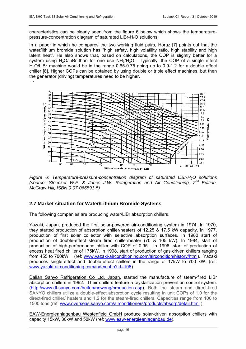
characteristics can be clearly seen from the figure 6 below which shows the temperature-pressure-concentration diagram of saturated LiBr-H2O solutions.
In a paper in which he compares the two working fluid pairs, Horuz [7] points out that the water/lithium bromide solution has “high safety, high volatility ratio, high stability and high latent heat”. He also shows that, based on calculations, the COP is slightly better for a system using H2O/LiBr than for one use NH3/H2O. Typically, the COP of a single effect H2O/LiBr machine would be in the range 0.65-0.75 going up to 0.9-1.2 for a double effect chiller [8]. Higher COPs can be obtained by using double or triple effect machines, but then the generator (driving) temperatures need to be higher.
Figure 6: Temperature-pressure-concentration diagram of saturated LiBr-H2O solutions (source: Stoecker W.F. & Jones J.W. Refrigeration and Air Conditioning, 2nd Edition, McGraw-Hill, ISBN 0-07-066591-5)
2.7 Market situation for Water/Lithium Bromide Systems The following companies are producing water/LiBr absorption chillers. Yazaki, Japan, produced the first solar-powered air-conditioning system in 1974. In 1970, they started production of absorption chiller/heaters of 12.25 & 17.5 kW capacity. In 1977, production of first solar collector with selective absorption surfaces. In 1980 start of production of double-effect steam fired chiller/heater (70 & 105 kW). In 1984, start of production of high-performance chiller with COP of 0.95. In 1996, start of production of excess heat fired chiller of 175kW. In 1998, start of production of gas driven chillers ranging from 455 to 700kW. (ref: www.yazaki-airconditioning.com/aircondition/history/html). Yazaki produces single-effect and double-effect chillers in the range of 17kW to 700 kW. (ref: www.yazaki-airconditioning.com/index.php?id=106) Dalian Sanyo Refrigeration Co Ltd, Japan, started the manufacture of steam-fired LiBr absorption chillers in 1992. Their chillers feature a crystallization prevention control system. (http://www.dl-sanyo.com/beifen/neweng/production.asp). Both the steam and direct-fired SANYO chillers utilize a double-effect absorption cycle resulting in unit COPs of 1.0 for the direct-fired chiller/ heaters and 1.2 for the steam-fired chillers. Capacities range from 100 to 1500 tons (ref: www.overseas.sanyo.com/airconditioners/products/absorp/detail.html ). EAW-Energieanlagenbau Westenfield GmbH produce solar-driven absorption chillers with capacity 15kW, 30kW and 50kW (ref: www.eaw-energieanlagenbau.de).

IEA SHC Task 38 Solar Air Conditioning and Refrigeration Subtask C1 Report, 31 October 2010
page 17
Trane, USA, produce hot-water absorption chillers, single stage from 112 to 1350 tons and two-stage from 380 to 1650 tons. (ref: www.trane.com/commercial/literaturesearchresults.aspx) Entropie, France, is an engineering company with expertise in the design of absorption chillers using Li Br. (www.entropie.com/en/about/ ). York, USA, produce single-stage absorption chillers from 120 to 1380 tons two-stage chillers from 200 to 700 tons. (ref: www.johnsoncontrols.com/publish/us/en/products/building_efficiency/integrated_hvac_systems/Industrial___Commercial_HVAC_Equipment/chiller_products.html ) ROTARTICA, Spain, are using rotation techniques to increase the efficiency of the absorption cycle, thereby reducing the size of the appliance and allowing it to be installed without the need for a cooling tower. They build a single-effect system specifically for solar application that gives a cooling power of 4.5 kW (in terms of solar cooling) with a COP of 0.7. (ref: http://www.rotartica.com) Broad, China, make two ranges of LiBr chillers:
(i) with a cooling capacity ranging from 233 to 11630 kW, with direct firing, as well as steam, hot water and waste heat firing.
(ii) With a cooling capacity from 23 to 115kW, direct firing. (ref: www.broad.com/english/include/en_index_pro.htm ) Carrier, USA, make LiBr chillers in the following configurations and sizes: single-effect, steam fired 100 to 700 tons single-effect hot water 75 to 525 tons double-effect, direct fired 100 to 1500 tons double-effect steam fired 98 to 1323 tons (ref:www.commercial.carrier.com/commercial/hvac/general/0,,11_CLI1_DIV12_ETI1508_MID4369,00.html ) Century, South Korea, produce hot-water driven absorption chillers from 28 to 650 tons, COP of 0.725; direct-fired two stage absorption chiller from 20 to 1500 tons, with crystallization prevention function; two-stage steam absorption chiller with crystallization prevention function from 70 to 1650 tons. (ref: www.century.co.kr:8080/product/in_wa_absorption.asp ) SolarNext have a 17.5kW LiBr chiller. (ref: www.solair-project.eu/uploads/media/10_Jakob_SolarNext.pdf ) Ebara Refrigeration Equipment and Systems Co Ltd, Japan, make double-effect LiBr absorption chiller from 528 to 2462, steam generated and single-effect hot water chillers from 158 to 1266 and single-effect steam or hot water from 334 to 5134 kW. (ref: www.ers.ebara.com/en/product/tantai/1.html ) Thermax, India, produce steam driven single and double-effect LiBr chillers from 50 to 4000 tons, low temperature (75ºC-110ºC) hot water driven chillers from 10-1159 tons, medium temperature (110ºC-150ºC) hot water driven from 100-2000 tons, high temperature (150ºC-200ºC) hot water driven from 100-2000 tons, gaseous or liquid fuel driven from 40-1500 tons, multi-energy (any combination of hot water, exhaust gases, fuel or steam) driven Vapor Absorption Machine from 50-4000 tons. (ref: www.thermxindia.com/v2/index.asp) Hitachi, Japan, produce steam double-effect LiBr machines from 422kW to 2708 kW; direct gas-fired double-effect from 527kW to 3165kW. (ref: www.hitachi-ap.com/acc/ref_v.html )

IEA SHC Task 38 Solar Air Conditioning and Refrigeration Subtask C1 Report, 31 October 2010
page 18
Sonnenklima, Germany, make a small LiBr m/c (10kW) that operates with low temperature heat (550C). (ref: www.sonnenklima.de ) A report on Absorption Chillers (dated May 2001) prepared under the SAVE II Programme called CHOSE, “Energy savings by CHCP plants in the Hotel Sector” includes a survey of Lithium Bromide machines. The report includes a list of suppliers, as well as a short discussion on single-effect machines, double-effect machines and small capacity low temperate machines. (ref: www.inescc.pt/urepe/chose/reports/B-absorption_chillers.pdf). The list includes many of the suppliers mentioned above as well as the following about which no information was found on the internet: LG Machinery, Korea McQuay, USA Mitsubishi, Japan Toshiba, Japan Kawasaki, Japan Kyung Won, Korea
2.8 Research and Development – Water/Lithium Bromide Systems This section lists organisations and individuals working in this field and projects relevant to LiBr, as well as some comments that were received in the course of this work. 1.The Department of Engineering Science of Martin-Luther University of Halle-Wittenberg have installed a 4.5 kW single-effect LiBr chiller with solar thermal collector. 2. Fundacion Cartif, Valladolid, Spain has been working on solar cooling since 1998, firstly through an ERDF (European Regional Development Funds) project, by means of which a solar air conditioning system was installed in its building and it has been kept working ever since 1999. The system is composed of a 40 m2 vacuum collector field (mounted on a solar tracking platform), and a 37.5 m2 flat collector field and a 35 kW absorption chiller for conditioning the administration area (200 m2). 3. ALONE Project, Small Scale Solar Cooling Device: University of Florence – CREAR (Italy, Coordinator), EURAC Research (Italy), DLR (Germany), Solitem (Turkey), AOSOL (Portugal), Ikerlan (Spain), Climatewell (Sweden) and Riello (Italy) are partners in a 7th Framework Projct ALONE, Small Scale Solar Cooling Device. The main aim of ALONE project is to overcome the lack of small scale units, developing fully automated and autonomous package-solutions for residential and small commercial or industrial solar cooling applications based on systems able to cope with low temperature cooling applications. Main efforts are on absorption chiller optimization for providing both heating and cooling in solar systems: in fact, adaptation of components and control logic optimization is a necessary step towards higher conversion performances and reduced costs. At four test sites three different solar cooling technologies will be applied (Ammonia system, Lithium bromide system, Lithium chloride system). The test sites are located in: Firenze (Italy) NH3 with MT, Alentejo (Portugal) NH3 with LT, Vitoria-Gasteiz (Spain) LiBr, and Bolzano (Italy) LiCl. 4. Ahmed Hamza H. Ali, PhD, Ibrahim M. Ismail PhD, M. G. Morsy PhD, and I. S. Taha PhD, Department of Mechanical Engineering, Faculty of Engineering, Assiut University, Egypt. 5.Prof. Felix Ziegler, Technische Universität Berlin, Institut für Energietechnik. http://www.eta.tu-berlin.de/felixziegler.html

IEA SHC Task 38 Solar Air Conditioning and Refrigeration Subtask C1 Report, 31 October 2010
page 19
6. Dr. Schweigler, ZAE Bayern, Dept I. http://www.zae.physik.tu-muenchen.de/deutsch/abteilung-1/arbeitsgebiete/kaeltemaschinen-und-waermepumpen.html 7. L. Richter, M. Kuhn, M. Safarik, ILK Dresden, www.ilk.de have worked on chilled water generation below 0 °C by a water-LiBr resorption cycle. 8. According to Peter Noeres (Fraunhofer UMSICHT), future R&D-perspectives are in the further development of small units to get better values of COP, better performance; air-cooled absorber/condenser, chiller with integrated recooling system; size/cost reduction; modification of the working pair to manage/avoid crystallization. 9. Report [9] by CHOSE for EU Directorate General for Energy (31/05/01) – Energy Savings by CHCP plants in the Hotel Sector – Absorption Chillers, already mentioned above. 10. Research group belonging to the Department of Habitability, Energy and Environmental Impact in Buildings of the Instituto de Ciencias de la Construcción Eduardo Torroja (CSIC) located in Madrid, Spain. They are working on three research projects on air cooled LiBr prototypes of small power and small size. The main results obtained are: Two air cooled double effect prototypes: one gas fired (2006-2007) and the other one driven by residual heat (2003-2006). One air cooled single effect prototype designed using recooling (1996). One Spanish patent (1999). One International Patent in edition phase (2007). 1982-1985. Solar cooling systems constructed in the Solar Energy Experimental Plant of CSIC in La Poveda, Arganda del Rey, Madrid. 1997-2004. Solar cooling system constructed in the Madrid Carlos III University R&D themes
• Development of absorbers of small size able to work with outdoor temperatures of around 40-42ºC.
• Simulation, design, construction and experimental evaluation of double effect lithium bromide-water, air cooled prototypes of small cooling power (below 10 kW).
• Simulation, design, construction and experimental evaluation of single effect lithium bromide-water, air cooled prototypes of small cooling power (below 10 kW).
• Air cooling lithium bromide systems driven by thermal solar energy. 11. Consortium for Alternative Cooling Technologies & Applications (ACTA), Center for Environmental Energy Engineering, University of Maryland. 12. Christopher Kren, Technical University of Munich – list of publications (1998-2007) indicates he is working on LiBr. 13. Powerpoint report by CSIRO Perspective on Renewable CHP & Absorption Refrigeration Laboratory, Dr Dong Chen and Dr Stephen White, National Energy Transformed Flagship, CSIRO, 14 May 2007, Renewable CHP. (ref: www.sustainability.vic.gov.au/resources/documents/CSIRO_Solar_Cooling.pdf ). 14. Infante Ferreira, C.A. [[email protected]], together with Dong-Seon Kim (now Arsenal Research) have been exploiting the advantages of half-effect LiBr-H2O absorption systems in combination with flat plate solar collectors to take advantage of the higher efficiencies at lower heating medium temperatures. 15. Egilegor Bakartxo [[email protected]], member of Ikerlan, which is an applied research center. Part of its Energy Group collaborates intensively with Rotartica in its products development. www.ikerlan.es. Latest innovations: The reliability of the systems

IEA SHC Task 38 Solar Air Conditioning and Refrigeration Subtask C1 Report, 31 October 2010
page 20
and control has been improved. Future R&D perspectives: the main R&D effort now is focused on the following topics: * Improved heat rejection systems in order to avoid cooling towers and improve the efficiency * Reduce the cost of the absorption units and the global installation * Definition of kits in order to make the installations easier and at lower cost
16. Polysmart, An Integrated Project partly funded by the European Commission under FP6, DG 'Energy and Transport' on POLYgeneration with advanced Small and Medium scale thermally driven Air-conditioning and Refrigeration Technology. The main purpose of the project was to support the development of the market for such technology. The work included a market analysis, the development of design models and tools, training and dissemination material, as well as a number of demonstration projects in various countries using different combinations of CHP and thermally driven chillers. http://www.polysmart.org
2.9 Relevant reports and publications – Water/Lithium Bromide Systems [7] Horuz I., A Comparison Between Ammonia-Water And Water-Lithium Bromide Solutions
in Vapour Absorption Refrigeration Systems, International Communications in Heat and Mass Transfer, vol. 25, No. 5, pp. 711-721, Elsevier, 1998.
[8] Kalogirou S., Florides G., Tassou S., Wrobel L., Design And Construction of a Lithium Bromide Water Absorption Refrigerator, 7th World Congress CLIMA 2000, Naples, 2001.
[9] Absorption Chillers, report prepared as part of the CHOSE (Energy Savings by CHCP plants in the Hotel Sector) project, SAVE II Progamme, Directorate-General for Energy, European Commission, May 2001.
[10] Estiot, E., Natzer, S., Harm, M., Kren, C., Schweigler, C., Heat Exchanger Development for Compact Water/Libr Sorption Systems, Proceedings of the International Sorption Heat Pump Conference, 2005, Denver, USA.
[11] Zogg R.A., Feng M.Y., Westphalen D., Guide to Developing Air-Cooled LiBr Absorption for Combined Heat and Power Applications, Distributed Energy Report, US Department of Energy, April 2005.
[12] Zogg, R. A., Feng, M., Westphalen, D., Developing Air-Cooled LiBr Absorption for Light Commercial Combined Heat and Power, Proceedings of the International Sorption Heat Pump Conference, 2005, Denver, USA.
[13] Killion, J., Garimella, S., Measurement of Local Absorption Rates in Films and Droplets in Lithium-Bromide/Water Absorbers, Proceedings of the International Sorption Heat Pump Conference, 2005, Denver, USA.
[14] Harm, M., Kren, C., Storkenmaier, F., Nogues, M., Schweigler, C., Experimental Evidence of the Vapor Surfactant Theory for Heat and Mass Transfer Enhancement in Water/Libr Absorption Chillers. Proceedings of the International Sorption Heat Pump Conference, 2005, Denver, USA.
[15] Estiot, E., S. Natzer, M. Harm, C. Kren, and S. Schweigler, Heat Exchanger Development for Compact Water/Libr Sorption Systems, American Society of Mechanical Engineers, Advanced Energy Systems Division (Publication) AES, 2006.
[16] Miyara, A., Islam, M.A, A Numerical Simulation of Steam Absorption by Wavy Falling Film of Libr Aqueous Solution, Proceedings of the 22nd International Congress of Refrigeration, 2007, Beijing.
[17] Takahashi, H., Koyama, S., Experimental Study of Falling Film Absorption Heat and Mass Transfer on the Horizontal Enhanced Heat Transfer Tube of Double Fluted Type with Libr Solution. Proceedings of the 22nd International Congress of Refrigeration 2007, Beijing.
[18] Clauß, V., Field Testing of a Compact 10 kW Water/LiBr Absorption Chiller, Proceedings of the 2nd International Conference on Solar Air-Conditioning, Tarragona, Spain, 2007.
[19] Macia A., Bujedo L.A., Vicente J., De Torre C., Development of a Model for the Simulation of an Absorption Chiller Air-Cooled “Rotartica” By TRNSYS, 3rd International Conference on Solar Air-conditioning, Palermo, 2009.

IEA SHC Task 38 Solar Air Conditioning and Refrigeration Subtask C1 Report, 31 October 2010
page 21
[20] Ajib S., Safarik M., Richter L., Kuhn M., Guenther W., Weidner G., Development of a 5 kW Absorption Chiller for Solar Installations, 3rd International Conference on Solar Air-conditioning, Palermo, 2009.
[21] El May S., Sayadi S., Bellagi A., Feasibility of Air-cooled Solar Air-conditioning in Hot Arid Climate Regions, 3rd International Conference on Solar Air-conditioning, Palermo, 2009.
[22] Marcos J.D., Izquiedo M., Lizarte R., Palacios E., Performance Optimization of a Water-Cooled Single-Effect Libr/Water Low Power Absorption Machine, 3rd International Conference on Solar Air-conditioning, Palermo, 2009.
[23] Rezai S.H., Witzig A., Wolf A., Pfeiffer M., Lacoste B., Modelling and Analyzing Solar Cooling Systems in Polysun, 3rd International Conference On Solar Air-Conditioning, Palermo, 2009.
[24] Jung S., Cagni A., Solar Cooling Application in Valle Susa Italy, 3rd International Conference on Solar Air-conditioning, Palermo, 2009.
[25] Asdrubali F., Baldinelli G., Presciutti A., An Experimental Solar Cooling System with a Small Size Absorption Chiller: Design and First Measurements, 3rd International Conference on Solar Air-conditioning, Palermo, 2009.
[26] Pospisil J., Chroboczek L., Skala Z., Small-Scale One Stage Libr-H2O Absorption Chiller with Identical Design of Desorber and Absorber, 3rd International Conference on Solar Air-conditioning, Palermo, 2009.
[27] Onda N., Yokoyama T., Oka M., Homma R., Kajiyama K., Demonstration and Field Test of a Solar Air Conditioning System with an Absorption Chiller/Heater Operated with Solar Thermal Energy and/or Gas Fuel for Commercial Buildings, 3rd International Conference on Solar Air-conditioning, Palermo, 2009.
2.10 New Advances In Absorption Lithium Bromide Technologies For Solar Refrigeration Marcelo Izquierdo Millán (Instituto de Ciencias de la Construcción Eduardo Torroja (CSIC), Universidad Carlos III de Madrid (UC3M)) and José Daniel Marcos del Cano (Universidad Nacional de Educación a Distancia (UNED)
2.10.1 Introduction The Eduardo Torroja Institute for Construction Science, a Spanish National Research Council (CSIC) body, is the sponsor of an "Energy Saving an Emissions Reduction in Buildings” research group. In 2006 the group set out to build several prototypes of low-power lithium bromide-water absorption chillers, capable of competing economically with mechanical compression chillers, an endeavour funded by Spain's Ministry of Science and Innovation under the INVISO (Industrialization of Sustainable Housing) sub-project "Generación Sostenible de Energía en Viviendas" (sustainable energy generation in housing). The first prototype was an air-cooled, direct-fired, double effect absorption chiller; the second a solar powered single effect air-cooled absorption chiller and the third a combination air-cooled, single-double-effect chiller, driven by solar power (or waste heat) while operating as a single-effect apparatus or by burning fuel in double-effect mode.
The development of such prototypes was contingent upon designing, building and testing a new generation absorber, smaller, more readily assembled and with higher mass and heat transfer coefficients than in place to date. This absorber was developed between 2003 and 2006 under research projects DPI 2002-02439 and ENE 2005-08255-CO2-01 with funding from Spain's Ministry of Industry. Once assembled and tested, the absorber was built into the 4.5kW; 7 kW and 10 kW power cooling prototypes.

IEA SHC Task 38 Solar Air Conditioning and Refrigeration Subtask C1 Report, 31 October 2010
page 22
2.10.2 Flat Sheet Adiabatic Absorber The falling film type absorbers presently used in lithium bromide absorption chillers are characterized by a number of problems: low mass transfer, low heat transfer and large volume.
The adiabatic spray absorber developed and patented by Ryan [28] as a solution, is not itself free of drawbacks. According to its inventor [29], these include:
a) Low liquid flow rate, calling for many spraying units. As a result, the absorber occupies a great deal of space.
b) Variable droplet diameter and a significant proportion with diameters under 150 µ. c) Droplets with diameters under 150 µ and, consequently, a substantial portion of the
pumped mass flow is of no use for absorption purposes [29]. d) Considerable head loss. High power demand in the pump that drives the solution.
In an attempt to solve these problems, Warnakulasuriya and Worek [30] developed a spray absorber with 400-micron diameter droplets. This device delivered higher mass transfer than Ryan's spray and multiplied the performance of commercial falling film absorbers by about four-fold.
Tackling the problem from a different angle, the Research Group modified the spray absorber, first by building a parallel droplet spray absorber, patented in Spain, able to generate droplets with no pressure loss and diameters of over 300 µ [31]. This absorber was not commercially viable because the mass of the solution was difficult to control and the mass transfer coefficient was similar to Ryan's. A jet absorber subsequently designed and built, also featuring no pressure loss, improved mass transfer but solution mass remained uncontrolled [32]. The next step was to develop a flat sheet absorber resting on a slanted surface [33] able to operate at a higher flow rate and therefore greater mass transfer. While it was also readily controlled, its need for material support constituted yet another difficulty. To solve these problems, two new adiabatic absorbers were studied: one generating a cone-shaped sheet [34 and 38] and the other a flat fan-shaped sheet with an oval nozzle [39].
This flat sheet adiabatic absorber, which consists of a bank of sprayers with an oval cross-section spaced at a minimum distance from one another, has been patented by Izquierdo et al. [37]. This arrangement increases both the mass transfer coefficient and the area available for mass transfer, significantly reducing volume. Moreover, since the flow rate is higher in sheet than in droplet sprays, absorber volume can be reduced even further. The process is readily controlled and pressure loss is small [39]. As an adiabatic unit, it transfers mass and heat separately [29].
Its operation involves pumping the solution from the absorber to the single generator in the single effect version or to the high and low temperature generators in the double-effect prototype. Similarly, the solution is pumped from the absorber and recirculated in a heat exchanger, where the absorption heat is transferred either to the outside air or to the water in a cooling tower. This characteristic affords adiabatic absorbers greater heat transfer capacity in a smaller exchange area than falling film absorbers [29].
After the device was tested, the results were published in the International Journal of Refrigeration [36], Energy Conversion and Management [38] and Applied Energy [39]. The paper “Evaluation of mass absorption in LiBr flat-fan sheets” [39] compared the mass transfer of a flat-sheet spray generated by an oval spray nozzle to Ryan's and Warnakulasuriya and Worek’s sprays. The conclusion drawn was that the mass transfer coefficient delivered by the flat-sheet spray was five times greater than by the Warnakulasuriya and Worek absorber. The improvement in mass transfer obtained with the flat-sheet absorber constitutes a significant development in absorber technology. This new generation of absorber is more efficient than Ryan's droplet spray and Warnakulasuriya and Worek's absorbers and than any commercial absorber in use today. The patent granted in 2009 in the European Union (PCT/EP2009/057061 and European Patent EP09162208.4)

IEA SHC Task 38 Solar Air Conditioning and Refrigeration Subtask C1 Report, 31 October 2010
page 23
was subsequently extended to the USA, Japan, China, Canada, Brazil, Argentina and Venezuela [37].
2.10.3 Single-Double Effect Chiller Prototype To the best of the authors’ knowledge, the first reference to a combination lithium bromide single-double effect absorption chiller appeared in US patent 4 439 999 entitled “Absorption Type Refrigeration System” and granted to Akio Mori, Shozo Watanabe, Mitsunubu Matshunada, Kenzy Machizawa and Ryohei Minowa. The patent protects a combination water-cooled single-double effect chiller in which the high-temperature double-effect chiller is powered by the heat released by internal combustion engine exhaust gases and the single-effect generator by the cooling heat from the same engine. Its claims include the use of exhaust gas in the double-effect high-temperature generator, cooling engine heat from the engine in the single-effect generator and spray in the absorber.
The new single-double effect prototype developed by this Research Group, patented in the European Union PCT/EP2009/057061 under European Patent EP09162208.4, features the following innovations:
Flat sheet adiabatic absorber able to operate in extreme outdoor temperatures (tested up to tex = 44 ºC), at which the solution does not crystallize.
Air-cooled (usable also for water-cooled systems) condensing to 54 ºC.
System for direct absorber and condenser cooling.
This combination single-double effect prototype, integrated into a solar cooling system, can use the heat from that renewable source (or the exhaust heat from an internal or external (turbine) combustion engine) to power the single-effect generator. When the renewable or exhaust heat is depleted, the system operates like a direct-fired double-effect facility in which fuel is burnt with maximum efficiency to supply heat to the high-temperature double-effect generator. Where a building’s demand is partially covered by renewable, solar or biomass energy or waste heat, the single-double-effect systems can be used simultaneously, burning fossil fuel in the double-effect system to meet all the building’s demand.
2.10.3.1 Description Figure 9 shows the absorption chiller prototype that alternates between single-double effect operation, in which a series of valves enables one system or the other. The prototype has three operating modes: single-effect, double-effect and simultaneous. The bold line represents fluid circulation in single-effect operation, in which only the valveS V1S, LEV, V3 AND V5, while the valves 1B, V2LG, V1, V2, V4 and HEV remain closed.
In double-effect mode, only the valves VIS, V3 and V5 are closed, while the valves 1B, V2LG, LEV, HEV, V1, V2 AND V4 remain closes. In simultaneous mode the solution pump (SP) feeds to all three generators.
The following components are common for the three operation modes: absorber (A), evaporator (E), condenser (C), solution pump (SP), recirculation solution pump (RSP), heat exchanger (HEX), fan (F). In the figure 4 we can see a photograph of the single-double effect.
Nominal cooling capacity of this prototype is 4,5kW in single effect mode operation; 7 kW working as double effect mode operation and 11 kW if the operation mode is single and double effect simultaneously.

IEA SHC Task 38 Solar Air Conditioning and Refrigeration Subtask C1 Report, 31 October 2010
page 24
Figure 9: Flow chart for the air-cooled single-double effect prototype
2.10.3.2 Experimental Results The prototype has been tested in single-effect operation mode during several days powered with thermal solar energy under environmental conditions of Madrid. The daily thermal COP obtained was between 0.55 and 0.7. The outlet evaporator chilled water temperature was between 15ºC and 17ºC when maximum outdoor temperature reached 38ºC. The maximum cooling power was 4.0 kW. No crystallization of the solution was observed.
Figure 8: Air-cooled, single-double effect lithium bromide absorption chiller prototype

IEA SHC Task 38 Solar Air Conditioning and Refrigeration Subtask C1 Report, 31 October 2010
page 25
2.10.4 Conclusions Today’s technology for thermally-driven domestic air-conditioning cannot compete with the cooling capacity of electric-powered air-cooled mechanical compression systems. Solar cooling systems use renewable energy, with a concomitant savings in fossil fuel. The initial investment is sizeable, however, while renewable energy is not always able to cover a building’s total demand and the power consumed by the ancillary equipment is excessive. As a result, cooling costs are higher than with the conventional system. Nonetheless, inasmuch as these technologies are environmentally friendly, a research effort should be made to solve the problems associated with their current state of development. Against this backdrop, the Subproject SP3, "Sustainable power generation in homes", part of a broader INVISO Project, proposes to modernize absorption cooling technology as a first move toward the development of viable solar-powered cooling systems, or systems fired by renewable energy in general, including waste heat.
The first step was to design and build a new adiabatic absorber that increases the mass transfer coefficient of falling film absorbers 18-fold and the Warnakulasuriya and Worek apparatus (an improved version of the Ryan absorber) five-fold. This absorber was then built into a prototype for an air-cooled, direct-fired, lithium bromide double effect absorption chiller of 7 kW nominal cooling capacity that has been experimentally proven to be competitive with the air-cooled mechanical compression chillers used for domestic air-conditioning. A second prototype was also developed, consisting of a similarly air-cooled, combination single-double effect chiller. In this prototype the heat from a renewable (solar) source or waste heat is supplied to the single-effect chiller. When this heat source is depleted, double-effect, fossil fuel-fired operation is enabled. The high efficiency of this facility reduces cooling costs. The prototype can also operate simultaneously as a single and double effect chiller, for the two share essential components such as the absorber, condenser, evaporator, pumps and so on. The research group presently plans to experiment with this mode of operation. The experimental results set out above show that lithium bromide solutions are effective in very high outdoor temperatures, up to 44 ºC, at which temperature they do not crystallize.
The conclusions that can be drawn from these results are:
Air-cooled, natural gas-fired double-effect facilities can compete with electric-powered air-cooled mechanical compression chillers.
Single-double-effect chillers fired by waste heat from trigeneration systems are competitive with mechanical compression chillers.
Integrated in a solar heating-cooling system, the present single-double effect chiller can significantly reduce cooling costs and is coming closer to being competitive with electric chillers.
2.10.5 Future Work The group’s future research will aim to:
Reduce the cost of collector fields, increasing their performance to reduce the area needed and raising energy generation.
Reduce the cost of auxiliary equipmentet used by absorption machines.
Increase absorption chiller efficiency.
2.10.6 Acknowledgements This research was funded by Spain's Ministry of Science and Innovation under the following projects: DPI 2002-02439; ENE 2005-08255-CO2-01 and the Subprogram SP3 of PSE INVISO. The authors wish to thank Emilio Martin, R&D Technician, for his enthusiastic contribution to this study.

IEA SHC Task 38 Solar Air Conditioning and Refrigeration Subtask C1 Report, 31 October 2010
page 26
2.10.7 References [28] William A. Ryan, System and process for operating an absorption cycle around a
crystallization curve of the solution Patent 5,255,534 (US), 1992. [29] William A. Ryan, Water absorption in an adiabatic spray of aqueous lithium bromide
solution, AES Vol. 31 International Absorption Heat Pump Conference, pp 155-162, (ASME 1993).
[30] Warnakulasuriya and Worek, International Journal of Heat and Mass Transfer 51, 3362–3368, 2008.
[31] M. Izquierdo, E. Martín, A. Lecuona, Absorbedor de gotas iguales de flujo paralelo. Spanish patent P9802674, Universidad Carlos III de Madrid (UC3M), 1998.
[32] Marcelo Izquierdo Millán, Emilio Martín Lázaro y Antonio Lecuona Neuman, Máquina de absorción de doble efecto enfriada por aire y alimentada por calor de los gases de escape de motores térmicos y su procedimiento de aplicación para climatización N. de solicitud: 9901979, Consejo Superior de Investigaciones Científicas (CSIC), 1999.
[33] D. Arzoz, P. Rodríguez and M. Izquierdo, Experimental study on the adiabatic absorption of water vapour into LiBr-H2O solutions, Applied Thermal Engineering, Vol 25/5-6, pp 797, 811, UK, 2005.
[34] E. Palacios, M. Izquierdo, R. Lizarte, J. D. Marcos, Water vapour absorption in lithium bromide aqueous solutions conical sheets, 8th IIR Gustav Lorentzen Conference, Copenhagen, September 2008, ISBN: 978-2-913149-63-2; ISSN: 0151.1637, 7-10.
[35] J.D. Marcos, M.Izquierdo, R.Lizarte, M.E Palacios, C.A. Infante-Ferreira, Experimental boiling heat transfer coefficients in the high temperature generator of a double effect absorption machine for the lithium bromide/water mixture Internacional Sorption Heat Pump Conference, Seoul (Korea), 23-26 September 2008.
[36] J. D. Marcos, M. Izquierdo, R. Lizarte, E. Palacios, C.A. Infante Ferreira, Experimental boiling heat transfer coefficients in the high temperature generator of a double effect absorption machine for the lithium bromide/water mixture, International Journal of Refrigeration, Vol. 32 pp. 627-637, 2009.
[37] M. Izquierdo, E. Martín and M.E. Palacios, Absorber and absorber-evaporator assembly for absorption machines and lithium bromide - water absorption machines that integrate said absorber and absorber-evaporator assembly, Patent PCT/EP2009/057061 y European Patent EP09162208.4 (extended to USA, Japan, China, Canadá, Brasil, Argentina, Venezuela), 2009.
[38] E. Palacios, M. Izquierdo, R. Lizarte, J.D. Marcos, Lithium bromide absorption machines: Pressure drop and mass transfer in solutions conical sheets, Energy Conversion and Management, 50 (2009) 1802–1809, 2009.
[39] E. Palacios, M. Izquierdo, J.D. Marcos, R. Lizarte, Evaluation of mass absorption in LiBr flat-fan sheets, Applied Energy 86 (2009) 2574–2582, 2009.
[40] M. Izquierdo; J. D. Marcos; M. E. Palacios; A. González; E. Martín, New advances in solar cooling and trigeneration systems, 8th expert meeting of Task 38 (IEA), Solar Air Conditioning and Refrigeration, April 26-27 Aarhus, Denmark, 2010.

IEA SHC Task 38 Solar Air Conditioning and Refrigeration Subtask C1 Report, 31 October 2010
page 27
3 Adsorption Chillers Tomas Núñez (Fraunhofer ISE)
3.1 General description of the technology Adsorption systems are very similar to absorption systems. The main difference is that the sorbent is a solid and not a liquid. The adsorption process is a physical process where the molecules of the working fluid or refrigerant are bound to the surface of the adsorbent by Van-der-Waals forces. Adsorbents used in adsorption chillers are very porous technical adsorbents like silica-gel, zeolites and activated carbons. The high porosity and thus extremely large internal surface of the adsorbents (several hundreds of m² per gram of material) allows the adsorption of a significant amount of refrigerant.
The main characteristic of the adsorbent-refrigerant pair is the amount of adsorbed refrigerant per unit of dry adsorbent.
),( pTxmm
xadsorbent
refrierant ==
The loading x is a function of refrigerant pressure and temperature and is represented in isosteric diagrams.
Figure 9 shows a typical isosteric diagram of the pair silica-gel / water.
The chilling cycle is carried out through four processes (Figure ):
1. isosteric heating: in section 1, the loaded adsorbent is heated at constant maximum loading xmax. The equilibrium pressure in the system increases until it reaches the condensation pressure of the refrigerant at condensation temperature Tcond.
2. isobaric desorption: the adsorbent is further heated up und thus desorbed at constant pressure. The desorption ends as soon as the maximum temperature Tmax provided by the external heat source is reached. This process is endothermic taking up the desorption heat. The released refrigerant is condensed in the condenser.
3. isosteric cooling: the desorbed material is cooled down until the equilibrium pressure reaches the evaporation pressure of the refrigerant in the evaporator.
4. isobaric adsorption: further cooling down of the adsorbent results in the adsorption process; refrigerant is evaporated in the evaporator, thus producing the cooling effect, and taken up by the adsorbent. The process ends as soon as the temperature of the adsorbent reaches the heat rejection temperature and closing the cycle.
The choice of the adsorbent depends on the affinity to the refrigerant and the envisioned application. The cooling energy Qcold in one cycle is proportional to the evaporation enthalpy hevap of the refrigerant and the loading difference xmax – xmin. These loading limits are given by the operation conditions: the minimum loading is given by the maximum desorption temperature TDes and the condensation temperature Tcond, the maximum loading by the evaporation temperature Tevap and the heat rejection temperature which is identical to the condenser temperature Tcond. The driving heat is given by the heat necessary for the isosteric heating Q1 and isobaric desorption Qdes. Thus, the thermal COP of an adsorption chiller is calculated as a first approximation through:
Des
evap
drive
coldth QQ
xxhQQ
COP+
−⋅==
1
minmax )(

IEA SHC Task 38 Solar Air Conditioning and Refrigeration Subtask C1 Report, 31 October 2010
page 28
280 300 320 340 360 380 400
1
10
Loading[gH2O
/gSiGel]
0.02 0.04 0.06 0.08 0.10 0.12 0.14 0.16 0.18 0.20 0.22 0.24 0.26 Ps(T)
Saturation curve water Ps(T)
Pres
sure
[kPa
]
Temperature [K]
Figure 9: Isosteric diagram of the adsorption pair silica-gel / water. The isosteres represent lines of constant loading x.
275 300 325 350 375 400
1
10
4
3
2
1
xmaxxmin
QEvap
QCond
QAds
Q3
QDes
Q1
TDesTDes,minTAds,maxTCond=TAds,minTEvap
pCond
Loading [g/g] 0.02 0.03 0.04 0.06 0.08 0.10 0.14 0.26 Ps(T)
Saturation curve water Ps(T)
Pres
sure
[kPa
]
Temperature [K]
pEvap
Figure 10: The adsorption cycle in the isosteric diagram of the silica gel / water adsorption pair.
In order to maximize the COP of an adsorption chiller the challenge is to increase the loading difference at the given boundary conditions and reduce the driving heat required from the external heat source. The first measure is achieved by specifically designed adsorption materials and adsorption pairs. This is still a research topic requiring basic material research. The second measure requires the reduction of the thermal masses for the adsorber and/or the implementation of an effective heat recovery in system designs with more than one adsorber. The typical design of an adsorption chiller is a two adsorber design. In this design two adsorbers are connected to a common evaporator and condenser via self-actuating flaps.
Figure shows a picture of a typical adsorption chiller.

IEA SHC Task 38 Solar Air Conditioning and Refrigeration Subtask C1 Report, 31 October 2010
page 29
Kühlwasser
Kühlwasser
Kaltwasser
Antriebswärme
KONDENSATOR
VERDAMPFER
ADSORBER DESORBER
Kältemittelrücklauf
automatische, innere Ventile
Wärmeübertrager mit SilicagelWärmeübertrager mit Silicagel
ADSORBER
CONDENSER
DESORBER
EVAPORATOR
chilled water
driving heat
cooling water
cooling water
heat exchanger with silica gelheat exchanger with silica gel
automatic internal valvescondensate return
Figure 11: Scheme of a typical adsorption chiller with two adsorption chambers, one evaporator and one condenser.
The two adsorber adsorption chiller is operated in four phases:
1. Phase 1: the left reactor is regenerated, the right reactor is in the adsorption phase.
2. Phase 2: heat from the left, hot adsorber is used to pre-heat the cold adsorber on the right hand side
3. Phase 3: is similar to phase 1 with exchanged adsorbers
4. Phase 4: similar to phase 2 with exchanged adsorbers.
Figure 12: The four phases of an adsorption chiller with two reactors.
3.2 Main characteristics
The time for the heat recovery is critical: on the one hand a very good heat recovery is necessary to achieve reasonable COPs, on the other hand during the heat recovery process normally no cold is produced, thus reducing the cooling power.
Desorption Adsorption
Kondensator
Verdampfer
Kondensator
Verdampfer
Kondensator
Verdampfer
Kondensator
Verdampfer
Phase 1
Phase 2
Phase 3
Phase 4
Adsorption Desorption
Wärmerückgewinnung Wärmerückgewinnung
condenser
condenser
condenser condenser
evaporator evaporator
evaporator
evaporator
desorption adsorption
adsorption desorption
heat recoveryheat recovery

IEA SHC Task 38 Solar Air Conditioning and Refrigeration Subtask C1 Report, 31 October 2010
page 30
Due to the intermittent, quasi continuous operation of such an adsorption chiller, the temperatures and thus the power in the three hydraulic circuits are fluctuating. Figure 13 shows a typical temperature curve of an adsorption chiller.
Depending on the construction type, the hydraulic circuits may be interrupted during the heat recovery phases.
hot water, in
hot water, out
cooling water, in
cooling water, outchilled water, in
chilled water, out
time [mm:ss]
tem
pera
ture
[°C
]
Figure 13: Typical temperature evolution in the forward and return lines of an adsorption chiller during operation.
Figure 14: Cooling capacity and COP of an adsorption chiller (Mycom ADR) as a function of hot water temperature for a chilled water temperature of 14°C / 9°C and different heat rejection temperatures.

IEA SHC Task 38 Solar Air Conditioning and Refrigeration Subtask C1 Report, 31 October 2010
page 31
The performance of an adsorption chiller depends on the operating conditions. High heat rejection temperatures reduce the COP and power of the machines. Typical COP values are around 0.6.
As normally there is no pump within the machine, the operation is almost noiseless. It is possible to modulate the power within a certain range but this affects the COP. Normally efficiencies are higher under part load operation.
The main advantages are:
• It is a robust technology with no risk of crystallization, no danger of damage due to temperatures.
• The materials used today (zeolite, silica gel) are environmentally friendly.
• Very low intrinsic electricity consumption due to the lack of a pump. Electricity is only required for the switching valves and the control unit.
• Very little moving parts with the potential of low maintenance effort and costs.
• High potential of cost reduction in series production due to the small amount of individual parts.
The main disadvantages are:
• High requirements of vacuum tightness of the container.
• Slightly lower COP than for comparable absorption technology.
• Cyclic temperature variation in the hydraulic circuits requires careful design of the external hydraulic circuits.
• Commercially available machines are expensive and only few suppliers on the market.
3.3 State of the art and present R&D topics The use of adsorption technology for cooling is a new technology compared to absorption technology. Thus, a lot of R&D is still going on in the field of material research, heat & mass transfer and component & machine development.
The next paragraphs describe the resent developments in the field of heat & mass transfer, working pairs, component development and projects involving state of the art chillers. A good overview of the techniques is also given in “Klimatisierung, Kühlung und Klimaschutz: Technologien, Wirtschaftlichkeit und C02 -Reduktionspotentiale: Materialsammlung“ [41] in German language. For a short English review see Wu et al. [41].
3.3.1 Heat & Mass Transfer A major focus of research in the field of adsorption chillers is on the topic of heat and mass transfer. Due to the fact that adsorption chillers are periodic working chillers, the COP is limited by the sensitive heat capacity of the adsorber. Therefore, the scope of the research is to reduce the weight of the chillers. This will lead to higher COPs. At the same time also the size of the chillers is in the focus of scientists. There is an urgent need of smaller and lighter adsorption chillers and therefore to increasing the specific cooling power per volume or mass. A good overview about the current state of the art in adsorber development can be found in Schnabel [47]. Research is now going on in the field of foams and sponges for compact adsorber development in order to increase the fraction of adsorbent coated surfaces to the required substrate mass; Bonaccorsi [49], Berg [48].

IEA SHC Task 38 Solar Air Conditioning and Refrigeration Subtask C1 Report, 31 October 2010
page 32
In order to increase the heat transfer coefficient between the substrate and the adsorbent two techniques are in the focus of research. One option is to glue the adsorbent onto the heat exchanger (see Zhu [58], and the patent of SorTech [76]. Moreover, several working groups work on the principle to directly crystallize adsorbent onto the heat exchanger substrate (Coronas [50] Beving [51], Yang [52], Scheffler [54], Tatlier [55] and SorTech [77]).
3.3.2 Working pairs A wide variety of working pairs are possible solutions for application in adsorption chillers. Wongsuwan [56], Srivastava [57] and Henninger [60] give an overview of possible working pairs. Most working pairs use water as the refrigerant due to the highest evaporation enthalpy of water compared to other possible working fluids. Furthermore, water is not toxic and easy to handle. The disadvantage of water is its limitation to applications above 0°C. For ice making or refrigeration below 0°C, methanol or ammonia as refrigerant is used with a variety of solid adsorbents; the main focus is on activated carbons.
The following section gives an overview of classical and modern adsorption materials as well as the latest developments. Here the first mentioned substance is the refrigerant, while the second mentioned is the adsorbent. With regards to the application in heat transformation processes, the main scope of research is the stability of materials – which means hydrothermal and mechanical stability of the pure material and possible composites and new synthesis routes, with regards to production costs. The focus is on template free syntheses and general investigations on the water vapour adsorption characteristics.
3.3.3 Classical working pairs Classical working pairs are water/zeolites, water/silica-gel and methanol/activated-carbon. A comparison between water/zeolite, water/silica-gel and methanol/activated-carbon can be found in San [72] or in the review of Dieng [71].
Zeolites are hydrated alumino-silicates which consist basically of SiO4 and AlO4. The coordination of these tethradrones form secondary building units which composes a 3- dimensional framework. Within this framework water can be adsorbed. In the “Atlas of Zeolite Framework Types” [62] 133 lattice types are known but the corresponding webpage now lists 179 different zeolite lattice types (June 2008). Hauer [61] and Henninger [60] give a good overview of zeolites and their properties.
Silica gels are solid, porous silicic acids produced by the synthetic dehydratisation of a hydro gel. Therefore, silica gel consists of more than 99% of SiO2. The porosity can be varied by the control of temperature and ph-value. Material properties can e.g. be found in Núñez [63], Ng [67] and Aristov [59].
Using methanol as the refrigerant, the solid adsorbent is in most cases activated carbon. This offers the possibility of refrigeration below 0°C. Physical properties are given in Carrott [68]. Wang [69] focuses on the heat and mass transfer in methanol/carbon working pairs. Stoeckli [73] also gives data about water/activated carbon.
3.3.4 Modern working pairs Modern working pairs are:
• water/selective-water-sorbents (SWS), • water/aluminium phosphates (AlPOs), • water/silica-aluminium phosphates (SAPOs) and • water/metal-aluminium phosphates (MAPOs).
Selective-water-sorbents (SWS) and selective-water-sorbents-like materials are a composition of an adsorbent and a salt, which means in principle that adsorption and

IEA SHC Task 38 Solar Air Conditioning and Refrigeration Subtask C1 Report, 31 October 2010
page 33
absorption occur at the same time, while the substrate is still solid. Aristov [59] introduced a salt impregnated silica gel. In Núñez [64] the potential of this material for heat storage was estimated.
AlPOs consist of alternating AlO2– and PO4
+ units, forming a similar structure like zeolites. The share of Al- and P-atoms is equal (besides lattice defects). The anion framework is electrically neutral but high electro-negativity leads to good adsorption characteristics. Properties are given e.g. Henninger [60]. In Jänchen [65] next to water also data for methanol as refrigerant are given.
SAPOs have a similar structure like AlPOs. They are based on AlO2– and PO4
+ units but some of the Al3+ ions are substituted by Si4+. Also, the embedding of FeO4 tetrahedrons is possible and already investigated (MeAPO). Information about these groups can be found in Jänchen [65] and Henninger [60]. A good overview of the embedding of metal ions into AlPOs is given by Rajic [66].
The most novel working pair is water/metal-organic-frameworks (MOFs). MOFs are based on an inorganic cluster, so to say, a coordinated network of inorganic compounds and connected together by a linker. The choice of the cluster and linker – the so called cluster/linker concept - allows varying the size of the cavity that is responsible for the uptake of refrigerant. MOFs are described by Henninger [60].
3.3.5 Component development Several working groups are working on the development of different components in adsorption chillers or in the enclosed system like evaporators, new heat storages, etc. The focus is on the development of adsorbers and the concept of heat & mass recovery between multiple adsorbers. The relevant documents for the development of adsorbers have already been mentioned in the paragraph about heat & mass transfer. In the area of heat & mass recovery during the switching process for adsorbers, two papers should be mentioned: Pons [82] reports about mass recovery – the recycling of refrigerant vapour, which is easily possible in adsorption chillers with two or more beds, and Schmidt [81] describes a new method to recycle heat with the help of stratified storage.
3.3.6 State-of-the-art Chillers Many projects demonstrate the working principle of adsorption chillers. The following is just a small list of applications.
The adsorption chiller described by Núñez [42] is now developed to the standard product of SorTech. Chwieduk et al [45] describe the SOCOOL project - two adsorption chillers working with heat sources at 200°C and 90°C. Working pairs are water/SWS1L and ammonia/activated-carbon.
De Boer [46] describes experiments with a 3,6 kW cooling power water/silica-gel adsorption chiller with hot water 80-90°C, cooling water 20-35°C and chilled water 6-10°C.
The group of Wang is working basically on two small scale adsorption chillers, a water/silica-gel adsorption chiller and an ammonia/activated-carbon adsorption chiller. A review is given in Wang [80]. Various reports (e.g. Wang [78] and Zhai [79]) show the development of the water/silica-gel adsorption chiller. More information about the ammonia/activated-carbon chiller, which is used for ice making can be found e.g. in Wang [70].
3.4 Suppliers The main suppliers of adsorption machines can be classified in two groups: suppliers of large machines with chilling powers above 70kW and suppliers of small machines. Today the only

IEA SHC Task 38 Solar Air Conditioning and Refrigeration Subtask C1 Report, 31 October 2010
page 34
provider of large adsorption chillers is the company Mayekawa from Japan offering Water-Zeolite machines with 108kW, 215kW and 429kW. For small machines two new players are offering their small-series products: SorTech from Germany (www.sortech.de) with an 8kW and 15kW water-silica gel chiller and the company Invensor also from Germany (www.invensor.de) with a 7kW and 10kW water-zeolite chillers. A further development has been carried out at the Shanghai Jiao Tong University in China but the status of the availability of a commercial machine is not known.
3.5 Literature list [41] SIMADER, Günter, RAKOS, Christian, Klimatisierung, Kühlung und Klimaschutz:
Technologien, Wirtschaftlichkeit und C02–Reduktionspotentiale – Materialsammlung. http://www.energyagency.at/(de)/publ/kkk_material.pdf - 7 March 2005 – Wien.
[42] WU, D.W., WANG, R.Z, Combined cooling, heating and power: A review. Progress in Energy and Combustion Science 32 (2006), p. 459-495.
[43] NÚÑEZ, T, MITTELBACH, W., HENNING, H-M., Development of a Small Capacity Adsorption System for Heating and Cooling Applications. International Sorption Heat Pump Conference (2005), June 22-24; Denver, Co, USA – proceedings.
[44] WANG, R.Z., KONG, X.Q., WU, J.Y., HUANGFU, Y., WU, D.W., Performance and Research of a Micro CCHP System with Adsorption Chiller. International Sorption Heat Pump Conference (2005), June 22-24, Denver, Co, USA – proceedings.
[45] CHWIEDUK, D., POMIERNY, W., CRITOPH, R.E., RESTUCCIA, G., FRENI, A., DE BOER, R., SMEDING, S.F., MALVICINO, C., Tri-generation in the tertiary sector. In: World Renewable Energy Congress VIII, 28.08.-03.09.2004, Denver, Colorado, USA – proceedings.
[46] DE BOER, R., SMEDING, S.F., GRISEL, R.J.H., Performance of silica-gel+water adsorption cooling system for use in small-scale tri-generation applications. Heat Powered Cycles Conference 2006 – proceedings.
[47] SCHNABEL, Lena, Experimentelle und numerische Untersuchung der Adsorptionskinetik von Wasser an Adsorbens-Metallverbundstrukturen. Technische Universität Berlin, Fakultät für Prozesswissenschaften, 2008, PhD-Thesis.
[48] BERG, A., BAUMEISER, J., RAUSCH, G., BUSSE, M., SCHNABEL, L., BAUER, J., Application of Aluminium Sponges in the Adsorption Refrigeration Engineering, 5th international Conference on Porous Metals and Metallic Foams (Montreal, Canada 2007) - conference proceedings.
[49] BONACCORSI, L., FRENI, A., PROVERBIO, E., RESTUCCIA, G., RUSSO, F., Zeolite coated copper foams for heat pumping applications. Microporous and Mesoporous Materials 91 (2006), p. 7-14.
[50] CORONAS, J., SANTAMARIA, J., The use of zeolite films in small-scale and micro-scale applications. Chemical Engineering Science 59 (2004), Vol. 22, p.4879-4885.
[51] BEVING, Derek E., O’NEILL, Cory R., YAN, Yushan, Hydrophilic and antimicrobial low-silica-zeolite LTA and high-silica-zeolite MFI hybrid coatings on aluminium alloys. Microporous and Mesoporous Materials 108 (Feb. 2008), p. 77-85.
[52] YANG, Guohui, ZHANG Xiongfu, LIU, Shuqin, YEUNG, King Lun, WANG, Jinqu, A novel method for the assembly of nano-zeolite crystals on porous stainless steel microchannel and then zeolite film growth. Journal of Physics and Chemistry of Solids 68 (2007), p. 26-31.
[53] BONACCORSI, Lucio, FRENI, Angelo, PROVERBIO, Edoardo, RESTUCCIA, Giovanni, RUSO, Fabio, Zeolite coated copper foams for heat pumping applications. Microporous and Mesoporous Materials 91 (2006), p.7-14.
[54] SCHEFFLER, Franziska, HERRMANN, Ralph, SCHWIEGER, Wilhelm, SCHEFFLER, Michael, Preparation and properties of an electrically heatable aluminium foam/zeolite composite. Microporous and Mesoporous Materials 67 (January 2004), pages 53-59.

IEA SHC Task 38 Solar Air Conditioning and Refrigeration Subtask C1 Report, 31 October 2010
page 35
[55] TATLIER, Melkon, DEMIR, Mesut, TOKAY, Begüm, ERDEM-ŞENATALAR, Ayşe, KIWI-MINSKER, Lioubov, Substrate heating method for coating metal surfaces with high-silica zeolites: ZSM-5 coatings on stainless steel plates. Microporous and Mesoporous Materials 101 (2007), p. 374-380.
[56] WONGSUWAN, W., KUMAR, S., NEVEU, P., MEUNIER, F., A review of chemical heat pump technology and applications. Applied Thermal Engineering 21 (2001), p. 1489-1519.
[57] SRIVASTAVA, N.C., EAMES, I.W., A review of adsorbents and adsorbates in solid-vapour adsorption heat pump systems. Applied Thermal Engineering 18 (1998), p. 707-717
[58] ZHU, Dongsheng, WANG, Shengwei, Experimental investigation of contact resistance in adsorber of solar adsorption refrigeration. Solar Energy 73 (2002), p. 177-185.
[59] ARISTOV, Yu. I., RESTUCCIA, G., CACCIOLA, G., PARMON, V.N., A family of new working materials for solid sorption air conditioning systems. Applied Thermal Engineering 22 (2002), p. 191-204.
[60] HENNINGER, Stefan, Untersuchung von neuen hochporösen Sorptionsmaterialien für Wärmetransformationsanwendungen. Albert-Ludwigs-Universität Freiburg, Fakultät für Mathematik und Physik, 2008, PhD thesis – http://www.freidok.uni-freiburg.de/volltexte/5264/
[61] HAUER, A., Thermal energy storage with zeolite for heating and cooling applications. International Sorption heat pump conference (2002), p. 385-390 – conference proceedings.
[62] BAERLOCHER, Ch., MEIER, W.M., OLSON, D.H., Atlas of Zeolite Framework Types. Elsevier, 5. edition, 2001. – http://www.iza-structures.org/databases
[63] NÚÑEZ, T., HENNING, H-M., MITTELBACH, W., Adsorption cycle modelling: Characterization and comparison of materials. ISHPC ’99, Proc. of the Int. Sorption Heat Pump Conference (1999) – conference proceedings.
[64] NÚÑEZ, T., HENNING, H-M., MITTELBACH, W., High energy density heat storage system – achievements and future work. 9th International Conference on Thermal Energy Storage, Futurestock 2003, Warsaw, Poland – conference proceedings.
[65] JÄNCHEN, Jochen, ACKERMANN, Dietrich, STACH, Helmut, Adsorption properties of aluminophosphate molecular sieves – potential applications for low temperature heat utilisation. ISHPC ’02 Proc. of Int. Sorption heat pump Conference (2002), p. 385-390.
[66] RAJIC, N., Open-framework aluminophosphates: synthesis, characterization and transition metal modifications. J. Serbian Chem. Soc. 70 (2005), p. 371-391.
[67] NG, K.C., CHUA, H.T., CHUNG, C.Y., LOKE, C.H., KASHIWAGI, T., AKISAWA, A., SAHA, B.B., Experimental investigation of the silica gel-water adsorption isotherm characteristics. Applied Thermal Engineering 21 (2001), p.1631-1624
[68] CARROTT, P.J.M., RIBEIRO CARROTT, M.M.L., CANSADO, I.P.P., Reference data for the adsorption of methanol on carbon materials. In: Carbon 39 (2001), p.193-200.
[69] WANG, L.W., WU, J.Y., WANG, R.Z., XU, Y.X., WANG, S.G., LI, X.R., Study of the performance of activated carbon-methanol adsorption systems concerning heat and mass transfer. Applied Thermal Engineering 23 (2003), p. 1605-1617
[70] WANG, L.W., WANG, R.Z., WU, J.Y., WANG, K., WANG, S.G., Adsorption ice makers for fishing boats driven by the exhaust heat from diesel engine: choice of adsorption pair. Energy Conversion and Management 45 (2004), p. 2043-2057.
[71] DIENG, A.O., WANG, R.Z., Literature review on solar adsorption technologies for ice-making and air-conditioning purposes and recent developments in solar technology. Renewable and Sustainable Energy Reviews 5 (2001), p. 313-342
[72] SAN, Jung-Yang, LIN, Wei-Min, Comparison among three adsorption pairs for using as the working substances in a multi-bed adsorption heat pump. Applied Thermal Engineering 28 (2008), p. 988-997.
[73] STOECKLI, F., Water adsorption in activated carbons of various degrees of oxidation described by the Dubinin equation. Carbon 40 (2002), p. 955-971.
[74] Industrial property rights EP 1391665-A3 (2003-08-19): ZAE Bayern. Pr.: DE 10237850-A1 2004-02-04. - Multistage absorption refrigerating apparatus or heat pump and the use of the apparatus in an energy conversion system.

IEA SHC Task 38 Solar Air Conditioning and Refrigeration Subtask C1 Report, 31 October 2010
page 36
[75] Industrial property rights WO 2008/ 034561 A2 (2008-03-27): Fraunhofer Gesellschaft. Pr.: DE 102006043715 A1 2008-03-27 - Adsorption Heat Pump With Heat Accumulator.
[76] Industrial property rights WO 2006/097198 A1 (2006-09-21): SorTech AG. Pr.: - Method For Producing An Adsorption Heat Exchanger.
[77] Industrial property rights WO 2006/048211 (2006-05-11): A2 SorTech AG. – Method For Production Of A Substrate Coated With A Zeolite Layer.
[78] WANG, D.C., WU, J.Y., WANG, R.R., XIA, Z.Z., Research on a novel adsorption chiller driven by low grade heat source. International Sorption Heat Pump Conference (2005), Denver, CO, USA – conference proceedings.
[79] ZHAI, X.Q., WANG, R.Z., WU, J.Y., DAI, Y.J., MA, Q., Design and performance of a solar-powered air-conditioning system in a green building. Applied Energy 85 (2008), p. 297-311.
[80] WANG, R.Z., Efficient adsorption refrigerators integrated with heat pipes. Applied Thermal Engineering 28 (2008), p. 317-326.
[81] SCHMIDT, Ferdinand P., FÜLDNER, Gerrit, SCHNABEL, Lena, HENNING, Hans-Martin, Novel cycle concept for adsorption chiller with advanced heat recovery utilising a stratified storage. Solar Air-Conditioning, Tarragona, Spain, 2007 – conference proceedings.
[82] PONS, M., POYELLE, F., Adsorptive machines with advanced cycles for heat pumping or cooling applications. International Journal of Refrigeration 22 (1999), p. 27-37.

IEA SHC Task 38 Solar Air Conditioning and Refrigeration Subtask C1 Report, 31 October 2010
page 37
4 Liquid Desiccant Systems Mustafa Jaradat (Kassel University), Michael Krause (Fraunhofer IBP),
Roland Heinzen (Kassel University), Lucio Mesquita (EnerWorks Inc.)
4.1 Principles of Operation
In liquid desiccant systems (LDS), air is dehumidified by being brought into contact with a strong solution of a liquid desiccant. Because of the dehumidification process, the solution is weakened by the absorption of moisture. In order to reuse the solution for further operation, it is directed to a regenerator where heat drives out the moisture. After that, the strengthened solution is returned to the dehumidifier. The main components of a liquid desiccant system are the absorber (dehumidifier) and the desorber (regenerator) shown in Figure 15.
Figure 15: Schematic diagram of a solar driven liquid desiccant air-conditioning system.
In order to use liquid desiccant systems for comfort air-conditioning, the system is extended by evaporative cooler or (cooling towers), which are either operated in the supply air stream to a building or using an additional heat exchanger in the return air. Usually, solution storage tanks that offer energy storage without energy losses are integrated in the system, making the system a very promising approach for the combination with solar thermal collectors.
4.2 Liquid desiccant systems for HVAC and cooling applications Liquid desiccant systems represent a particular configuration of a more generic class of cooling and air-conditioning systems called open-absorption systems. In such systems, the chemical solution used to absorb water is in direct contact with atmospheric air. This contact can occur at the regenerator/desorber, at the absorber/dehumidifier, or at both. The direct contact with atmospheric air is in contrast with closed absorption systems, which are referred to in the literature simply as absorption systems. Figure 16 shows a liquid desiccant system with desiccant storage operating as a ventilation cycle.

IEA SHC Task 38 Solar Air Conditioning and Refrigeration Subtask C1 Report, 31 October 2010
page 38
Figure 16: Liquid desiccant air-conditioning system, ventilation cycle. Source: Mesquita [83].
Herold et al. [84] presented the principles of operation and thermodynamic analysis of such systems. A schematic of a single-effect LiBr-H2O cycle is shown in Figure 17.
Figure 17: Schematic of a single-effect LiBr-H2O closed absorption cycle.
Source: Mesquita [83].

IEA SHC Task 38 Solar Air Conditioning and Refrigeration Subtask C1 Report, 31 October 2010
page 39
Figure 18: Schematic of an open-absorption system. Source: Mesquita [83].
Collier [85] analyzed what is commonly referred to as the open-absorption refrigeration system. In such a system, the closed desorber from a conventional absorption system is substituted for an open one, in this case an open solar collector. The author used a solution of LiCl-H2O, with water being the refrigerant. Since the system is open, water is spent in the desorber/collector and has to be reintroduced into the system in the evaporator. Figure 18 presents a schematic of such a system. Lowenstein et al. [86] suggested an LDS with a closed boiler as the desorber/regenerator. Such a system, represented in Figure 19, could also be classified as an open-absorption system. One could argue that such a system represents more closely the definition of open-absorption, since the absorption is open and the desorption is closed.
Figure 19: Schematic of a liquid-desiccant system with a closed desorber.
Source: Mesquita [83]

IEA SHC Task 38 Solar Air Conditioning and Refrigeration Subtask C1 Report, 31 October 2010
page 40
Perhaps a more appropriate nomenclature would be to call such systems semi-open absorption systems. Therefore, there would be a clear distinction between closed, semi-open and open-absorption, where both absorption and desorption are in direct contact with air. The fact that liquid-desiccant systems are usually used for dehumidification is not enough to clarify the nomenclature in the literature. For example, Grossman [87] proposed a system with an open regenerator and absorber, where the dehumidified air was directed to a cooling tower. This way, the system generated chilled water, as in a traditional vapour compression or closed absorption system. Bolzan and Lazzarin [88], Lazzarin et al. [89], and Johansson and Westerlund [90] presented systems that were liquid-desiccant cycles with open absorbers and regenerators, where the air running through the absorber was the air to be conditioned. Although this is an arrangement that has been mostly referred to as a desiccant system, the authors labelled the system as open-absorption.
One advantage of LDS over solid desiccant and closed absorption systems is the flexibility in terms of heat sources for regeneration and heat sinks for the dehumidification process. Heat can be supplied by any medium temperature source, usually above 60°C. Cooling can be accomplished by the use of heat sinks providing moderately low temperatures, usually between 5 and 25°C.
4.3 Applications Liquid desiccant systems are growing in popularity because of their ability to independently control humidity levels (latent loads) moisture without cooling the air to saturation, the supply air relative humidity falls below 70%. This keeps supply ducts dry and helps avoid mold and bacterial growth. In addition, the scavenging action of liquid desiccant systems could improve indoor air quality by removing airborne contaminants. Heinzen et al. [91] presented a comprehensive overview for the liquid desiccant applications.
Figure 20: Liquid desiccant air drying process, from source to application. Source: Heinzen et al. [91].
Figure 20 shows a schematic of the liquid desiccant air drying process in the dashed area. It presents possible driving heat sources (left), the coupling to different cooling technologies (center right) and possible applications where LDS can be technically viable and economically and ecologically useful (right).

IEA SHC Task 38 Solar Air Conditioning and Refrigeration Subtask C1 Report, 31 October 2010
page 41
Lowenstein [86] presented the applications of LDS coupled with cooling processes that can be used for:
● comfort air-conditioning in offices, public and residential buildings
● warehouses and production halls for preservation and archiving purposes
● condensation protection to prevent mould and rust destruction from equipment
● production processes e.g. in the food production, pharmaceutical production, semi-conductor production, rubber industry, confectioneries.
The air stream from the absorber can be used directly for:
● high efficiency heat recovery and indirect air heating in low energy buildings, Kerskes [92]
● low temperature drying of agricultural goods and industrial products (“gentle drying”), Rane [93]
● high efficiency heat recovery and humidity control for indoor swimming pools and greenhouses, Waldenmaier [94].
4.4 Technology status In the last years, significant progress has been made in the basic components of desiccant technology. These include:
4.4.1 Desiccant materials The behaviour of all desiccant system components is profoundly influenced by the operating characteristics of the desiccant materials they contain. Recognizing this fact, research institutions and manufacturers have focused on material science to develop desiccants which are especially suited to air-conditioning applications.
These efforts have had two primary goals; to develop desiccants which:
1. Use less energy for reactivation and therefore need less energy for cooling
2. Are more stable and fault-tolerant and therefore require less maintenance
Al-Farayedhi et al. [95] listed several important considerations in choosing or designing the optimal liquid desiccant solution for a dehumidification application:
• High vapor pressure of water in solution
• Low vapor pressure of solute
• Performance of solution steady over large concentration range
• Non-corrosive and chemically stable
• Low viscosity
• High solubility
• Low regeneration temperature
• Non-toxic, harmless
• Low cost
Lithium chloride (LiCl), Calcium Chloride (CaCl2), Lithium Bromide (LiBr), and tri-ethylene glycol (TEG) are common liquid desiccant materials meeting the above performance characteristics to varying degrees. LiCl and CaCl2 dominate the most recent research efforts into liquid desiccant dehumidification systems. Wimby and Berntsson [96] investigated aqueous solutions of various desiccants, including LiCl and CaCl2, producing experimental data of density as a function of temperature and mass fraction. This data is of critical importance when experimenting with liquid desiccant materials, providing concentration as a

IEA SHC Task 38 Solar Air Conditioning and Refrigeration Subtask C1 Report, 31 October 2010
page 42
function of density, which is relatively easy to measure in the laboratory. A mixture of LiCl and CaCl2 was the subject of a study by Ertas, Anderson, and Kiris [97]. LiCl has excellent regeneration performance and stability but high cost, while CaCl2 has lower performance but low cost. A mixture of the two at various ratios was analyzed to produce functions of vapor pressure for various temperatures. In an important study of aqueous LiCl and CaCl2, Conde [98] gathered data from 1850 and onwards and fitted empirical curves to selected data.
Functions of density, heat capacity, enthalpy of dilution, vapor pressure, solubility, and others, were presented. These correlations were used extensively in the present study. The concept of storage was explicitly investigated by Peng, Zhang, and Yin [99], with the conclusion that liquid desiccant regeneration equipment performance is improved with desiccant storage.
4.4.2 Desiccant-air contactors In desiccant systems, the component which presents the desiccant to the air stream (the desiccant contactor) is one of the most critical elements of the system, and the one which most influences the net energy consumption of the system.
Ideally, the desiccant contactor would have an infinitely large surface area for desiccant-air interaction, but infinitely low mass, so no excess material must be heated and cooled along with the desiccant. Further, the contact media must be very durable, as it is repeatedly wetted and dried as the desiccant moves through the sorption-desorption cycle.
There are many different technologies available for the absorber and regenerator. The regeneration can be built as a packed bed, heated coil, spray chamber, falling-film parallel plates, boiler or open solar collector. As for the absorbers, they are typically built as packed beds, cooled coils, spray chambers and falling-film parallel plates.
4.4.2.1 Packing towers A packed tower arrangement sprays liquid desiccant into the process air stream in counter flow, through a random or structured packing material. Figure 21 presents examples of random packings used in packed beds and columns. The bed or column is filled with such random packings, forming the contacting surface.
Figure 21: Commercially available random packings for packed beds. Source: Koch-Glitsch [100].
Packed bed design was first proposed by Lof [101] in 1955 using a triethylene glycol solution as the desiccant. This design incorporates a porous packing material, sprinklers, and a solution pump. The concentrated liquid desiccant is sprayed over the packing material, which forms a thin film along the bed. Similar to a cooling tower design, the inlet air is forced through the packed bed structure in a counter-flow direction, where the weight of the desiccant enables collection at the bottom of the bed. The packed bed structure has been

IEA SHC Task 38 Solar Air Conditioning and Refrigeration Subtask C1 Report, 31 October 2010
page 43
extensively studied by Factor and Grossman [102] with exit condition predictions using a one-dimensional model. Their analysis included a set of differential equations derived from energy and mass balances along a differential slice of the packed column. A finite difference scheme was used to solve these sets of differential equations, revealing the temperature and humidity profiles along the bed.
Industrial dehumidification systems usually employ packed bed regenerators and absorbers, with high flow rates of desiccant. In a review of liquid desiccant systems, Öberg and Goswami [103] showed that typical systems have an MR of between 0.5 and 2. On the other hand, low desiccant flow and internally cooled absorbers can use an MR above 100, as shown by Keßling et al. [104].
As pointed out by Dudukovic et al. [105], packed beds, packed towers or packed columns are widely used in the pharmaceutical, chemical and petroleum industries. Therefore, extensive research has been conducted on the design and operation of such technology. Strigle [106] and Billet [107] present extensive information on packed towers. This type of equipment is relatively cheap and easy to build, and provides elevated interfacial surface area per unit volume (specific surface area).
Regarding the specific application of packed beds for liquid-desiccant dehumidifiers and regenerators, Öberg and Goswami [103] presented a review of mass transfer performance correlations available in the literature, most of them using random packings. More recently, a number of studies, both theoretical and experimental, have been published on structured packing dehumidifiers and regenerators, e.g., Al-Farayedhi et al. [108], Gandhidasan et al.[109], Abdul-Wahab et al. [110], Dai and Zhang [111], Elsarrag et al.[112], Elsarrag [113] and Liu et al. [114]. Longo and Gasparella [115] experimentally compared the performance of structured and random packings. Their results showed dehumidification rates and an efficiency that was 20% to 30% higher for random packings, but a 65 to 75% lower air pressure drop with structured packings. Besides the high pressure drop, packed beds have a number of disadvantages associated with high desiccant flow rates.
Lowestein et al. [86] listed the most important disadvantages associated with packed beds:
• air passages within the packed bed are fairly wide to prevent the desiccant from restricting the airflow (flooding). This increases the size and cost of equipment;
• desiccant pumps are large and therefore have high energy consumption;
• the change in concentration of the desiccant is slight, making the desiccant storage not viable and less effective;
• desiccant flow is high leading to more heat being dumped back into the dehumidifier cooler by the regenerator; and
• air velocities are low to avoid high pressure drops and entrainment of droplets in the air stream.
4.4.2.2 Plate Type / Falling Film The problem of droplet entrainment and desiccant carry-over into building ducts can be a significant issue associated with packed beds. Mist eliminators require regular maintenance, which is usually not available in many buildings.
In order to avoid some of the shortcomings of packed beds, parallel-plate, internally-cooled or heated absorbers and regenerators have been proposed. In such systems, such as the one shown in Figure 22, the desiccant solution trickles down the surface of a plate, where it contacts the air to be dehumidified. Water flows inside a channel to remove the heat generated by the absorption process.

IEA SHC Task 38 Solar Air Conditioning and Refrigeration Subtask C1 Report, 31 October 2010
page 44
Figure 22: Parallel-plate, internally-cooled/heated absorber/regenerator, Krause et al. [116]
Different techniques, [117] Jaradat et al. and Hubliz [118], have been presented in order to introduce the liquid desiccant into the plates, the uneven horizontal distribution of the liquid desiccant as it enters the generator is undesirable because it reduces the effective area of contact between the liquid desiccant and air and thus decreases the mass transfer and heat exchange between the liquid and vapour. To ensure proper operation of the generator, it is also important to ensure that the ratio of liquid to vapour is constant over the cross-section of the plates. For this reason, it is important to have an even distribution of liquid as it enters the heat and mass exchanger. Figures 23 and 24 show different distribution techniques of the liquid desiccant over the heat and mass transfer plates.
Figure 23: Schematic diagrams of a liquid desiccant distributor; perforated pipes concept: Jaradat et al. [117]

IEA SHC Task 38 Solar Air Conditioning and Refrigeration Subtask C1 Report, 31 October 2010
page 45
Figure 24: Schematic diagrams of different liquid desiccant distributors; channel concept (upper) and outlet concept integrated into the heat and mass transfer plate (lower). Hublitz [118].
Another option is to provide cooling through an internal evaporative cooler. In such systems, as proposed by Saman and Alizadeh [119] and shown in Figure 25, the desiccant and evaporating water flow on opposite sides of the same wall. The air to be conditioned flows on the desiccant side. The scavenging air, which can also be the exhaust air from the building, flows on the water side. These absorbers are potentially more economical and compact than the water channel cooled varieties. The additional stream of air and the coupled evaporative cooler, however, make its construction significantly more complex. The additional complexity comes from building an absorber with two streams of air, one stream of desiccant and one stream of water, and ensuring no leakages/contamination between the two air streams.
Figure 25: Schematic of an evaporatively cooled absorber. Source: Saman and Alizadeh [119].
The main disadvantages and challenges of the plate-type liquid desiccant heat and mass exchanger are:
1. Difficult to construct, especially when internally cooled designs are used in a “three-way heat exchanger”. Here, a mixing of the different fluids has to be prevented

IEA SHC Task 38 Solar Air Conditioning and Refrigeration Subtask C1 Report, 31 October 2010
page 46
2. Difficult flow operation to ensure an even flow distribution over plates 3. Wetting difficulties when using low flow rates of desiccant solution 4. High material requirements, e.g. when used plastic material for plates
4.5 New developments of desiccant cooling systems • L-DCS (Germany, Singapore): Advanced open cooling system using liquid desiccant
in a plate heat and mass exchanger approach. Due to low flow rates, concentrated solution offers storage with high energy density. Three systems are currently in operation.
• Other liquid sorption developments: Kassel University (Germany), Stuttgart (Germany), Queens University (Canada), University of South Australia (Adelaide), Technion Haifa (Israel), Florida (U.S.), Genius (U.S.). Different prototypes, Figures 26 and 27, have been built with different materials and ideas in order to overcome the obstacles that hinder the progress and wide acceptance of such systems in the HVAC industry.
Figure 26: Non-adiabatic liquid desiccant absorber/regenerator made-out of polypropylene, University of South Australia, Krause [116]
Figure 27: Non-adiabatic liquid desiccant absorber/regenerator (left) and adiabatic liquid desiccant absorber (right) made-out of polycarbonate in the pilot plant stage in the laboratories of Kassel University. Jaradat et al [120].

IEA SHC Task 38 Solar Air Conditioning and Refrigeration Subtask C1 Report, 31 October 2010
page 47
4.6 Commercial products suppliers • Kathabar (USA): Packed bed (Raschig rings) Kathabar Systems has manufactured desiccant dehumidification equipment for over 70 years. This company provides a wide range of dehumidifiers and regenerators. A total of 14 different size conditioners is available, each capable of handling either horizontal or vertical air flow arrangements. The smallest in the series is designed to handle airflows from 1274 to 2548 m3/h, the largest from 71,358 to 142,716 m3/h. Kathabar offers a total of eight different size regenerators which are matched with the conditioners required for a given installation, Figure 28.
Figure 28: A commercially available packed bed liquid desiccant dehumidifier (Kathabar, 2007) [121].
• AIL Research: provide commercially liquid desiccant dehumidifiers and regenerators that are based on parallel-plate liquid-to-air heat exchanger. The dehumidifier is capable of handling airflows from 3398 to 10194 m3/h, Figure 29.
Figure 29: Rooftop Liquid-Desiccant Air Conditioner (left), schematic of an AIL Research Liquid Desiccant dehumidifier. Source: Lowenstein et al. [122].
• Liquid-Desiccant Air Conditioner Menerga (Germany): New air handling unit using liquid sorption, dehumidifier in combination with a standard indirect evaporator cooler. Four pilot plants are currently in operation, one is operated using solar thermal energy (Freiburg, Germany), Figure 30.

IEA SHC Task 38 Solar Air Conditioning and Refrigeration Subtask C1 Report, 31 October 2010
page 48
Figure 30: Menerga air handling unit using liquid sorption technology. Biel et al. [123].
4.7 References [83] Lucio Cesar De Souza Mesquita. Analysis of a Flat-Plate, Liquid-Desiccant, Dehumidifier
and Regenerator. PhD thesis, Queen’s University, 2007. [84] Herold, K.E., Radermacher, R., and Klein, S.A. (1996) Absorption Chillers and Heat
Pumps, CRC Press. [85] Collier, R.K. (1979) The Analysis and Simulation of an Open Cycle Absorption
Refrigeration System, Solar Energy Journal, vol. 23 (4), pp. 357-366. [86] Lowenstein, Slayzak, Ryan, Pesaran (1998), Advanced Commercial Liquid-Desiccant
Technology Development Study, Report Proj.-No. NREL/TP-550-24688, National Technical Information Service (NTIS) U.S. Department of Commerce, 5285 Port Royal Road Springfield, VA 22161, 703-605-6000 or 800-553-6847.
[87] Grossman, G. (2002), Solar-Powered Systems for Cooling, Dehumidification and Air-Conditioning, Solar Energy, vol. 72 (1), pp. 53-62.
[88] Bolzan, M. and Lazzarin, R. (1979), Comparison between Two Absorption Cooling Systems of The ‘Open’ Type Under Different Climatic Conditions, International Journal of Refrigeration, vol. 2 (3), pp. 143-149.
[89] Lazzarin, R.M., Longo, G.A. and Gasparella, A. (1996), Theoretical Analysis of an Open-Cycle Absorption Heating and Cooling System, Int. J. Refrig., vol.19 (3), pp. 160-167.
[90] Johansson, L. and Westerlund, L. (2000), An Open Absorption System Installed at a Sawmill - Description of Pilot Plant Used for Timber and Bio-Fuel Drying, Energy, vol.25, pp. 1067–1079.
[91] Heinzen R., Krause M., Jordan U., Vajen K., Technical Potential of Solar Thermal Driven Open Cycle Absorption Processes for Industrial and Comfort Air Conditioning, Proc. ISES Solar World Congress, Beijing, 18.09. - 21.09.2007, pp. 809 – 813
[92] Kerskes H., Heidemann W., Müller-Steinhagen H. (2004), MonoSorp- Ein weiterer Schritt auf dem Weg zur vollständig solarthermischen Gebädeheizung, 14. Symposium Thermische Solarenergie OTTI Energie-Kolleg.
[93] Rane M. V., Reddy S. V. K., Easow R. R. (2005), Energy efficient liquid desiccant-based dryer, Applied Thermal Engineering, Vol. 25, pp. 769 – 781.
[94] Waldenmaier M., A Sorption Heat Storage System for Dehumidification of Indoor Swimming Pools, IEA Annex 10, Phase Change Materials and Chemical Reactions for Thermal Energy Storage, First Workshop, 16 - 17 April 1998, Adana, Turkey.
[95] Al-Farayedhi A.A., Gandhidasan P. M., Antar A., and Abdul Gaffar M.S., Experimental study of an aqueous desiccant mixture system: air dehumidification and desiccant regeneration. Proceedings of the Institution of Mechanical Engineers, Part A (Journal of Power and Energy), 219(A8):669 – 80, 2005.

IEA SHC Task 38 Solar Air Conditioning and Refrigeration Subtask C1 Report, 31 October 2010
page 49
[96] J. Martin Wimby and Thore S. Berntsson. Viscosity and density of aqueous solutions of LiBr, LiCl, ZnBr2, CaCl2, and LiNO3. 1. single-salt solutions. Journal of Chemical and Engineering Data, 39:68 – 72, 1994.
[97] Ertas, E.E. Anderson, and I. Kiris. Properties of a new liquid desiccant solution-lithium chloride and calcium chloride mixture. Solar Energy, 49(3):205 – 12, 1992.
[98] Manuel R. Conde. Properties of aqueous solutions of lithium and calcium chlorides: Formulations for use in air conditioning equipment design. International Journal of Thermal Sciences, 43(4):367 – 382, 2004.
[99] Donggen Peng, Xiaosong Zhang, and Yonggao Yin. Theoretical storage capacity for solar air pre-treatment liquid collector/regenerator. Applied Thermal Engineering, 28(11-12):1259 – 66, 2008.
[100] Koch-Glitsch (2003), Intalox Packed Tower System, Plastic Random Packing, Wichita, Kansas.
[101] Löf, House heating and cooling with solar energy. Solar Energy Research, pages 33–46, 1955.
[102] Factor, H. M., Grossman, G., A packed bed dehumidifier/regenerator for solar air conditioning with liquid desiccants. Sol. Energy 1980, 24, 541.
[103] Öberg, V. and Goswami, D. (1998), A Review of Liquid-Desiccant Cooling, in Advances in Solar Energy, Böer, K., Ed. American Solar Energy Society, Boulder, Colorado.
[104] Keßling W., Lävemann, E. and Kapfhammer, C. (1998), Energy Storage for Desiccant Cooling Systems Component Development, Solar Energy, vol. 64 (4-6), pp. 209-221.
[105] Dudukovic, M.P., Larachi, F. and Mills, P.L. (1999), Multiphase Reactors Revisited, Chemical Engineering Science, vol. 54, pp. 1975-1995.
[106] Strigle, R.F. (1987), Random Packings and Packed Towers: Design and Applications, Gulf Pub. Corporation.
[107] Billet, R. (1995), Packed Towers: in Processing and Environmental Technology, VCH. [108] Al-Farayedhi, A.A., Gandhidasan, P. and Al-Mutairi, M.A. (2002), Evaluation of Heat and
Mass Transfer Coefficients in a Gauze-Type Structured Packing Air Dehumidifier Operating with Liquid Desiccant, International Journal of Refrigeration, vol. 25, pp. 330– 39.
[109] Gandhidasan, P., Al-Farayedhi, A.A. and Antar, M. A. (2002), Investigation of Heat and Mass transfer in a Gauze-Type Structured Packing Liquid Desiccant Dehumidifier, International Journal of Energy Research, vol. 26, pp. 1035-1044.
[110] Abdul-Wahab, S.A., Zurigat, Y.H. and Abu-Arabi, M.K. (2004), Predictions of Moisture Removal Rate and Dehumidification Effectiveness for Structured Liquid Desiccant Air Dehumidifier, Energy, vol. 29, pp. 19–34.
[111] Dai, Y.J. and Zhang, H.F. (2004), Numerical Simulation and Theoretical Analysis of Heat and Mass Transfer in a Cross Flow Liquid Desiccant Air Dehumidifier Packed with Honeycomb Paper, Energy Conversion and Management, vol. 45, pp.1343–1356.
[112] Elsarrag, E., Magzoub, E.E.M. and Jain, S. (2004), Mass-Transfer Correlations for Dehumidification of Air by Triethylene Glycol in a Structured Packed Column, Ind. Eng. Chem. Res., American Chemical Society, vol. 43, pp. 7676-7681, 2004.
[113] Elsarrag, E. (2006), Performance Study on a Structured Packed Liquid Desiccant Regenerator, Solar Energy, vol. 80, pp. 1624–1631.
[114] Liu, X.H., Zhang, Y, Qu, K.Y. and Jiang, Y. (2006), Experimental Study on Mass Transfer Performances of Cross Flow Dehumidifier Using Liquid Desiccant, Energy Conversion and Management, vol. 47, pp. 2682–2692.
[115] Longo, G.A. and Gasparella, A. (2005), Experimental Analysis on Chemical Dehumidification of Air in a Packed Column by Hygroscopic Salt Solution: Comparison between Structured and Random Packings, International Sorption Heat Pump Conference, Denver, Colorado.
[116] Krause, M., Heinzen, R., Saman, W., Vajen, K., Jordan, U. (2007), Validation and Comparison of Absorber and Regenerator Models for Liquid Desiccant Air Conditioning Systems. 2nd. Intern. Conference Solar Air Conditioning, Taragona (Spain), 18.-19.10.2007

IEA SHC Task 38 Solar Air Conditioning and Refrigeration Subtask C1 Report, 31 October 2010
page 50
[117] Jaradat, M., Heinzen, R., Jordan, U., Vajen, K., A Novel Generator Design for a Liquid Desiccant Air Conditioning System, EuroSun 2008, Lisbon (PO), 07.10 - 10.10. 2008.
[118] Astrid Hublitz. Efficient Energy Storage in Liquid Desiccant Cooling Systems. PhD thesis, Technische Universität München.
[119] Saman, W.Y. and Alizadeh, S. (2002), An Experimental Study of a Cross-Flow Type Plate Heat Exchanger for Dehumidification/Cooling, Solar Energy,vol.73(1), pp.59-71.
[120] Jaradat, M., Heinzen, R., Jordan, U., Vajen, K., Initial Experiments of a Novel Liquid Desiccant Dehumidifier for Industrial and Comfort Air Conditioning Systems, proceeding 3rd International Conference Solar Air-Conditioning 2009, Palermo (IT), 30.09 - 02.10 2009.
[121] Kathabar Systems (2007), website accessed: 07 September 2009 (www.kathabar.com/products/dehumidifiers/liquiddesiccant.html ).
[122] Lowenstein, A. I., A. S. Slayzak, E. Kozubal, A zero carryover liquid-desiccant air conditioner for solar applications, ISEC 2006.
[123] Biel, S.,et al. (1997), Sorption Entfeuchtung unde Temperaturabsenkung bei der klimatisierung, Final Report on the BMB+F Project 032 9151J.

IEA SHC Task 38 Solar Air Conditioning and Refrigeration Subtask C1 Report, 31 October 2010
page 51
5 Solid desiccant cooling systems
Paul Bourdoukan, Etienne Wurtz, (LOCIE-INES/CNRS) 5.1 Desiccant cooling principle Using solar energy appears to be an interesting option for cooling applications, as the building load almost matches the availability of the source. In a solar desiccant cooling cycle, solar energy is used to regenerate a desiccant that dehumidifies moist air; the resulting dry air is cooled in a sensible heat regenerator and then in an evaporative cooler. By associating different elementary changes in moist air (dehumidification, sensible cooling and evaporative cooling) the technique uses water as a refrigerant and solar energy as a driving heat; while electricity is only used in the auxiliaries, so the technique is environmentally friendly. It is a thermally driven open cooling cycle based on evaporative cooling and adsorption. With reference to figure 31, a desiccant cycle operates as follows: outside air (1) is dehumidified in a desiccant wheel (2); it is then cooled in the sensible heat regenerator (3) by the return cooled air before being further cooled in an evaporative process (4), finally, it is introduced into the building. The operating sequence for the return air (5) is as follows: it is cooled to its saturation temperature by evaporative cooling (6) and then it cools the fresh air in the rotary heat exchanger (7). It is then heated in the regeneration heat exchanger by solar energy (8) and finally regenerates the desiccant wheel (9) by removing the humidity before exiting the installation. The desiccant wheel is used to remove moisture from the outside air. Its function is first, to reduce the humidity of the outside air in order to match indoor air standards and second, to provide extra dehumidification to increase the cooling potential of the supply humidifier. Depending on load conditions this system can operate under different modes. Simple ventilation (fans only), indirect evaporative cooling for low cooling loads (fans, return evaporator cooler and the sensible heat regenerator) and desiccant mode (all components operational). For moderate summer conditions, in the morning when the outside temperature is low, the indirect evaporative cooling mode is able to keep the room in a comfortable range; there is thus no need for regeneration and the solar heated water can be stored in the tank. During the day with the outside temperature rising and increasing solar gains the indirect evaporative cooling cannot provide the cooling and so the desiccant mode is then required, while solar energy is needed for the regeneration of the desiccant wheel. The minimum temperature required for regeneration depends on the nature of the desiccant material. It varies from 50°C for lithium chloride to 60°C for silica gel. We chose silica gel for its higher dehumidification performances in spite of the higher temperature needed for its regeneration. The desiccant cooling process is well-suited to the requirements of non-residential buildings with high occupancy needing high air exchange rates, e.g. seminar rooms and banks. In these buildings the rooms are usually occupied during the day, so air-conditioning loads match solar energy availability; so coupling desiccant cooling with solar collectors would seem a very interesting option.

IEA SHC Task 38 Solar Air Conditioning and Refrigeration Subtask C1 Report, 31 October 2010
page 52
Figure 31: Desiccant cooling installation with corresponding evolution of moist air properties in the psychrometric chart. 5.1.1 Advantages The main advantages of the desiccant cooling system are the following:
• The minimum required driving temperature is 50°C which makes the coupling to solar collector a very interesting option.
• Different operating modes can be used depending on load conditions. This allows operations on partial loads while storing solar energy for peak loads.
• The use of electricity is limited to the auxiliaries. • The process uses water as a refrigerant.

IEA SHC Task 38 Solar Air Conditioning and Refrigeration Subtask C1 Report, 31 October 2010
page 53
5.1.2 Disadvantages The disadvantages of a desiccant cooling system are:
• The cooling potential depends intrinsically on operating conditions (outside temperature, outside humidity ratio and regeneration temperature).
• If the humidifiers are not carefully designed, they may cause hygienic problems. • Rotating elements (desiccant wheel, sensible heat regenerators) need maintenance.
5.2 What is on the market? In this section the market development concerning desiccant cooling technologies will be developed. A conventional desiccant air-handling unit consists of a desiccant wheel, a sensible heat regenerator, and evaporator coolers. For the sensible regenerator and the evaporator coolers, these components are conventionally used in the HVAC air-handling units. This market development section will consider only desiccant wheels as these are not conventionally used and the manufacturers are limited worldwide. This list is of course not exhaustive, it is the result of the author’s queries and research. USA Novel Air Address: 10132 Mammoth Ave., Baton Rouge, Louisiana 70815-8013, USA website: http://www.novelaire.com/technologies/desiccant.htm Tel: +1-(225)-924-0427 Fax: +1-(225)-930-0340 Germany Klingenburg GmbH Address: Boystraße 115, 45968 Gladbeck, Germany Website: http://www.klingenburg.de/en/index.html Tel.: +49 (0) 20 43 / 96 36-0 Fax: +49 (0) 20 43 / 7 23 62 Sweden Munters Europe AB Address: Östra Nygatan 104,931 35 Skellefteå, Sweden Website: http://www.munters.se Tel: +46 (0)10-451 54 69 Fax: +46 (0)910-521 99 Proflute Address: 18732 Täby, Sweden Website: www.proflute.se Tel: +46 8 511 87 800 Fax: +46 8 511 87 700 Japan Seibu Giken Co. Ltd. Address: 3108-3 Aoyagi, Koga-shi, Fukuoka, 811-3134 Japan Website: http://www.seibu-giken.co.jp/eg/products/dry_save.html Tel: +81-92-942-3511 Fax: +81-92-942-3761 Earth Clean Tohoku Co. Ltd. Address: Sendai City, Japan 984-0038 Website: http://www.earthclean.co.jp/products/desiccant/catalog.html

IEA SHC Task 38 Solar Air Conditioning and Refrigeration Subtask C1 Report, 31 October 2010
page 54
Tel: +81-22-288-2888 Fax: +81-22-288-2890 Amefrec Co. Ltd. Address: 8-15, Toyosaki 2-Chome, Kita-Ku, Osaka 531-0072, Japan Website: http://www.amefrec.co.jp/afceng/index.htm Tel: +81-6-6373-3201 Fax: +81-6-6373-3290 Panasonic Ecology Systems Co. Ltd. Address: 4017, Shimonakata, Takaki-cho, Kasugai-city, Aichi 486-8522 Japan Website: http://www.panasonic.net/corporate/segments/pes/ Tel: +81-6-6908-1121 Mitsubishi Plastics Inc. Address: 1-2-2, Nohonbashihongokucho, Chou-Ku, Tokyo, 103-0021, Japan Website: http://www.mpi.co.jp Tel: +81-3-3279-3700 China The major desiccant system producers are mainly located in southeast of China, where is nearing the application market as shown in Figure 1. There are also some companies located in Beijing, whose products are distributed all over the whole country. The information about the main companies is summarized and introduced below: Munters Air Treatment Equipment (Beijing) Co. Ltd. It is a subsidiary of world famous dehumidification products producer Munters group. Products of Munters entered China in 1970s. It is also one of the earliest foreign companies that established its manufacturing factory in China (in 1995), which is their biggest manufacturing base in Asia. They have branch offices in Beijing, Shanghai and Guangzhou to provide products and services in the most demanding markets of China. Their products are usually in the higher price and high quality bracket (better supply air accuracy and operational reliability). Their industry customers include ABB China, Shanghai Volkswagen, Towngas, Trane etc. Their commercial customers include Walmart, Nestle etc. Website: http://www.munters.cn/cn/cn/Contact/ Tel: +86-10-8041-8000 Fax: +86-10-8048-3493 Dryer Air-handling Equipment Co. Ltd. It was founded in 2001. It is a joint venture with the Swedish manufacturer and supplier of desiccant (adsorption) dehumidifiers and desiccant cooling equipment, DehuTech AB. The desiccant rotor, which is patented, is manufactured in Sweden. Their head office and manufacturing base are in Shanghai with branch offices located in Beijing, Guangzhou and Chongqing. Similar to Munters, the products of Dryer are in the higher price and high quality bracket. This company has been awarded dehumidification projects for some famous bridges in China such as Lupu Bridge in Shanghai, Jiangshu Runyang Bridge, Yichang Changjiang Bridge etc. Website: http://www.dryer-inc.com/cn/contact.asp Tel: +86-10-8225-1978 Fax: +86-10-8225-1978 Sat Air Treatment Co. Ltd. It was founded in 2000 and is a joint venture with the Swedish company PROFLUTE. It is located in Jiangying, Jiangshu Province. In the beginning, they made evaporative cooling

IEA SHC Task 38 Solar Air Conditioning and Refrigeration Subtask C1 Report, 31 October 2010
page 55
equipment for henhouses as well as workshops. This company started to manufacture desiccant dehumidification equipment in 2004 with rotors imported from PROFLUTE. Website: http://www.sat.net.cn/contact.asp Tel: +86-510-8660-5998 Fax: +86-510-8660-5978 Wuxi Shamo Dehumidifying Equipment Co. Ltd It was founded in 1990 and is one of the oldest dehumidifying equipment manufacturers. Their rotor is self made with paper as substrate. Their products are usually in the lower price and medium quality range. Hence, they have substantial market share among medium or low end users who do not require high accuracy/operational reliability but cost effective products. Website: http://www.shamo.cn/index_e.asp Tel: +86-510-8310-9612 Fax: + 86-510-8375-0058 Wuxi Aobo Dehumidifying Equipment Co. Ltd. They make their own brand equipment with rotors imported from the Swedish company PROFLUTE. Website: http://www.aobocs.com/english/ Tel: +86-510-8320-3593 Fax: +86-510-8320-3470 Hangzhou Dry Air Co. Ltd. It was established from a paper research institute in Zhejiang Province. They make their own brand equipment with rotors imported from Swedish company PROFLUTE and Japanese company NICHIAS. Their products have been used in some defence applications. Website: http://www.hzdryair.com/doce/index2_en.asp Tel: +86-571-8990-5556 Fax: +86-571-8990-5538 Hangzhou Fuda Co. Ltd. It was founded in 1995. Their employees include the first generation specialists in rotary desiccant equipment in China. This is a typical local desiccant dehumidification equipment producer with market mostly in east China. Their products are mainly for small and medium size industry application. Website: http://www.hzfdcs.com/# Tel: +86-571-8689-9396 Fax: +86-571-8689-9390 Shanghai Hanfu Air Treatment Equipment Co. Ltd. It is also a joint venture. Their rotors are from Swedish Proflute, Japanese Nichias, Swedish Enuentus. They have produced moveable products that can provide heating, cooling, dehumidification according to requirements. Website: http://www.hanfuair.com/ Tel: +86-21-5759-9990 Fax: +86-21-5759-6329 Guangzhou Huagongtai Dehumidification Equipment Co. Ltd. It is a subsidiary company of the National Science Park of South China University of Technology. Its market is mainly in South China Guangdong Province. Their rotors are self made with patent technology. Website: http://www.gdscw.com/company/com/index.php?newsid=19540 Tel: +86-20-8754-2392 Fax: +86-20- 8711-2101

IEA SHC Task 38 Solar Air Conditioning and Refrigeration Subtask C1 Report, 31 October 2010
page 56
5.3 Research and Development and References In this section the research and development worldwide will be reported. It concerns institutions, universities and companies involved in the field of solar desiccant cooling. The enumeration of institutions etc. will be on country basis. This list is of course not exhaustive; it is the result of the author’s query and research. France LEPTIAB: Université de La Rochelle Research: LEPTIAB carried out numerical and experimental investigation of a solar desiccant cooling system. Corresponding researchers:
Paul Bourdoukan: [email protected] Patrice Joubert: [email protected]
Relevant publications: [124] Bourdoukan, P., Wurtz, E., Joubert, P., and Sperandio, M., (2008) “Potential of solar
heat pipe vacuum collectors in the desiccant cooling process: modelling and experimental results." Solar Energy. 82(12), 1209-1219.
[125] Bourdoukan, P., Wurtz, E., Joubert, P., and Spérandio, M. (2008). "Overall cooling efficiency of a solar desiccant plant powered by direct flow vacuum tube collectors: simulation and experimental results" Journal of Building Performance Simulation 1(3), 149-162
[126] Bourdoukan, P., Wurtz, E., Joubert, P. (2009). "Comparison between the conventional and recirculation modes in desiccant cooling cycles and deriving critical efficiencies of components”. Energy an international journal, in press corrected proof.
[127] Bourdoukan, P., Wurtz, E., Joubert, P. (2009). "Experimental investigation of a solar desiccant cooling system" Solar Energy, accepted for publication
[128] Bourdoukan, P., Wurtz, E., Joubert, P., and Spérandio, M. (2008). "A control strategy to prevent the impact of outside and load conditions on the hygro-thermal performance of a desiccant cooling system." In proceedings of Indoor Air conference, Copenhagen, Denmark. CD-Rom
[129] Bourdoukan, P., Wurtz, E., Joubert, P., and Sperandio, M. (2008). "Critical efficiencies of components in desiccant cooling cycles and a comparison between the conventional mode and the recirculation mode." In proceedings of ECOS conference, 1, 435-443. Krakow, Poland.
[130] Bourdoukan, P., Wurtz, E., Joubert, P., and Spérandio, M. (2008). "A sensitivity analysis of a desiccant wheel" In proceedings of Eurosun conference, Lisbon, Portugal. CD-Rom
[131] Bourdoukan, P., Wurtz, E., Sperandio, M., and Joubert, P. (2007). "Global efficiency of direct flow vacuum collectors in autonomous desiccant cooling: simulation and experimental results." In proceedings of Building Simulation conference, 1, 342-347. Beijing, China.
LOCIE-INES/CNRS Research: In the field of desiccant cooling systems, LOCIE carries out numerical investigation of desiccant systems. Corresponding researchers:
Paul Bourdoukan: [email protected] Etienne Wurtz: [email protected]

IEA SHC Task 38 Solar Air Conditioning and Refrigeration Subtask C1 Report, 31 October 2010
page 57
Relevant publications: [132] Bourdoukan, P., Wurtz, E., Joubert, P. (2009). "Comparison between the conventional
and recirculation modes in desiccant cooling cycles and deriving critical efficiencies of components”. Energy an international journal, in press Corrected proof.
[133] Bourdoukan, P., Wurtz, E., Joubert, P. (2009). "Experimental investigation of a solar desiccant cooling system" Solar Energy, accepted for publication
CEA-INES Research: CEA-INES is investigating a new desiccant exchanger cooled by water besides some model development for desiccant wheel. Corresponding researchers:
Philippe Papillon: [email protected] François Boudéhenn: [email protected]
Relevant publications:
[134] Clausse M., Meunier F., Perigaud Y., Boudehenn F. & Demasles H., Experimental characterisation of a novel adsorber heat exchanger for desiccant cooling applications, Article, 22nd IIR International Congress of Refrigeration, Beijing (Chine), 21-26 August 2007.
[135] Demasles H., Boudehenn F. & Clausse M., Numerical and experimental studies of a novel adsorber heat exchanger for desiccant solar air conditioning, Article, 2nd International Conference Solar Air-Conditioning, Tarragone (Espagne), 18-19 October 2007.
[136] Boudehenn F. & Burgun F., Technical analysis of desiccant cooling systems, Article, 2nd Workshop of EMINENT project, Weszprem (Hongrie), 05-06 May 2008.
[137] Clausse M., Meunier F., Perigaud Y., Boudehenn F. & Demasles H., Experimental investigation and building integration of a novel adsorber heat exchanger for solar desiccant cooling applications, article, International Sorption Heat Pump Conference 2008, Seoul (Corée), 23-26 September 2008.
CETHIL-INSA Lyon Research: CETHIL developed mainly numerical model for desiccant cooling systems Corresponding researchers:
Jean Brau: [email protected] Relevant publications: [138] Thibaut Vitte, Jean Brau, Nadège Chatagnon and Monika Woloszyn, “Proposal for a
new hybrid control strategy of a solar desiccant evaporative cooling air handling unit”, Energy and Buildings, In Press, Corrected Proof , Available online 25 July 2007.
EDF, Electricité de France Research: In association with CETHIL, EDF research domain is the simulation of desiccant cooling systems. Corresponding researcher:
Nadège Chatagnon: [email protected] China In China, some research institutes have conducted extensive investigation work on solid desiccant cooling systems. Information about these institutes is listed below:

IEA SHC Task 38 Solar Air Conditioning and Refrigeration Subtask C1 Report, 31 October 2010
page 58
Shanghai Jiao Tong University Research: carried out lots of investigations in the past years relating to desiccant cooling systems, such as desiccant material, construction of solid desiccant wheel and desiccant cooling system. Corresponding researchers:
Prof. Ruzhu Wang ([email protected] ) Prof. Yanjun Dai ([email protected] ).
Relevant publications: [139] X.J. Zhang. Study on Dehumidification Performance of Silica Gel-Haloid Composite
Desiccant Wheel. PhD Thesis, Shanghai Jiao Tong University, Shanghai, China; 2003 [in Chinese].
[140] C.X. Jia, Y.J. Dai, J.Y. Wu, R.Z. Wang. Experimental comparison of two honeycombed desiccant wheels fabricated with silica gel and composite desiccant material, Energy Conversion and Management 2006, 47(15-16): 2523-2534.
[141] C.X. Jia, Y.J. Dai, J.Y. Wu, R.Z. Wang. Use of compound desiccant to develop high performance desiccant cooling system, International Journal of Refrigeration 2007, 30(2): 345-353.
[142] C.X. Jia, Y.J. Dai, J.Y. Wu, R.Z. Wang, Analysis on a hybrid desiccant air-conditioning system, Applied Thermal Engineering 2006, 26(17-18):2393-2400.
[143] Ge TS, Li Y, Wang RZ, Dai YJ. Experimental study on a two-stage rotary desiccant cooling system. International Journal of Refrigeration 2009; 32 (3): 498-508.
[144] Ge TS, Dai YJ, Wang RZ, Li Y. Experimental investigation on a one-rotor two-stage desiccant cooling system. Energy 2008; 33 (12): 1807-15.
[145] K. Daou, R.Z. Wang, Z.Z. Xia. Desiccant cooling air conditioning: a review. Renewable and Sustainable Energy Reviews 2006, 10(2): 55-77.
[146] Y.J. Dai, R.Z. Wang, Y.X. Xu. Study of a solar powered solid adsorption desiccant cooling system used for grain storage, Renewable Energy 2002, 25(3): 417-430.
South China University of Technology Research: investigated lots of different desiccant materials. Corresponding researcher:
Prof. Jing Ding ([email protected] ). Relevant publications: [147] J. Ding, X.X. Yang, G.Q. Li, S.Z. Liang, Y.K. Tan. Sorption equilibrium of microporous
active silica gel and the effect of sorption properties on the performance of the desiccant rotary dehumidifiers, Chemical Engineering 1998, 26:11-13. (in Chinese).
Beijing University of Aero & Astro Research: conducted some work on solid desiccant cooling systems recently. Corresponding researcher:
Weixing Yuan ([email protected] ). Relevant publications: [148] W.X. Yuan, Y. Zheng, X.R. Liu, X.G. Yuan. Study of a new modified cross-cooled
compact solid desiccant dehumidifier. Applied Thermal Engineering 2008, 28(17-18): 2257-2266.

IEA SHC Task 38 Solar Air Conditioning and Refrigeration Subtask C1 Report, 31 October 2010
page 59
[149] W.X. Yuan, Y. Zheng, H. Wang, X.G. Yuan, C.X. Yang. Study of transient dehumidifying performance of an internally cooling compact solid dehumidifier, Acta Energiae Solaris Sinica 2007, 28(1):7-11. (in Chinese).
[150] Y. Zheng, W.X. Yuan. Study of solar/waste heat driven solid desiccant cooling system. Refrigeration And Air-Conditioning 2006, 6(5):5-9. (in Chinese).
[151] Y. Zheng, W.X. Yuan, H. Wang, X.G. Yuan. Experiments on dynamic dehumidification of internally cooling compact solid dehumidifier. Journal of Beijing University of Aeronautics and Astronautics 2006, 32(9):1100-1103.
Tong Ji University Research: studied the performance of solid desiccant cooling system. Corresponding researcher:
Chaokui Qin ([email protected] ). Relevant publications: [152] Y. Xu, C.K. Qin. The Solar-driven Solid Desiccant Dehumidification Air-conditioning
System, Shanghai Gas 2007, 1:27-30. (in Chinese). Japan Tohoku University Research: Numerical simulation of desiccant cooling systems Corresponding researcher:
Hiroshi Yoshino: [email protected] Relevant publications: [153] N. Enteria, H. Yoshino, A. Mochida, R. Takaki, R. Yoshie, T. Mitamura, S. Baba,
Construction and Initial Operation of the Combined Solar Thermal and Electric Desiccant Cooling System, Solar Energy, Vol. 83, Issue 8, pp. 1300-1311 (2009).
[154] N. Enteria, H. Yoshino, A. Mochida, R. Takaki, R. Yoshie, T. Mitamura, S. Baba, Synergization of Clean Energy Utilization, Clean Technology Development and Controlled Clean Environment Through Thermally Activated Desiccant Cooling System, 2008 ASME International Conference on Energy Sustainability “ASME ES” (August 10-14, 2008), Jacksonville, Florida, USA. Proceedings of ASME ES 2nd International Conference (ISBN 0-7918-3832-3), Paper No. ES2008-54103.
Tokyo University of Agriculture and Technology Research: Corresponding researcher
Prof. Atsushi Akisawa Graduate School of Bio-Applications and Systems Engineering Tokyo University of Agriculture and Technology Naka-Cho 2-24-16, Koganei-shi, Tokyo, Japan Tel: +81-42-388-7076 Fax: +81-42-388-7226 Webpage: http://www.tuat.ac.jp/~akilab/index.html
Relevant Publications: [155] S. Elsayed, Y. Hamamoto, A. Akisawa, T. Kashiwagi, Using Air Cycle Refrigerator
Integrated with Desiccant System for Simultaneous Air Conditioning and Domestic Hot

IEA SHC Task 38 Solar Air Conditioning and Refrigeration Subtask C1 Report, 31 October 2010
page 60
Water Heating, Journal of Environment and Engineering, Vo. 2, No. 3, pp. 514-524 (2007).
[156] Y. Hamamato, T. Tran, A. Akisawa, T. Kashiwagi, Experimental and Numerical Study of Desiccant Rotor with Direct Heating Regeneration by Solar Energy, 6th ASME-JSME Thermal Engineering Joint Conference, March 16-20, 2003. Paper No. TED-AJ03-273.
Tokyo University Research: Corresponding researcher:
Shinsuke Kato Environmental Technology for Urban Architecture Institute of Industrial Science Tokyo University 4-6-1 Komaba, Meguro-Ku Tokyo, 153-8505 Japan Tel: +81-3-5452-6431 Fax: +81-3-5452-6432 Website: http://venus.iis.u-tokyo.ac.jp/english/default.htm
Relevant Publications: [157] Y. Tsay, S. Kato, R. Ooka, M. Koganei, N. Shoda, Study on the Applicability of
Combining Desiccant Cooling System with Heat Pump in Hot and Humid Climate, ASHRAE Transactions, Vol. 112, Part 1, pp. 189-194 (2006).
[158] Y. Tsay, S. Kato, R. Ooka, M. Koganei, N. Shoda, K. Nishida, K. kawamoto, Study on Non-Condensing Air-Conditioning System – Performance when Combining Desiccant Cooling System with CO2 Heat Pump, HVAC&R Research, Special Issue, Vol. 12, No. 3c, pp. 917-933 (2006).
Kanazawa University Research: Corresponding researcher:
Akio Kodama ([email protected] ) Technology and Human Communication Laboratory Department of Human and Mechanical Systems Engineering Kanazawa University Kanazawa, Ishikawa, 920-1192 Japan Tel: +81-76-234-4663 Fax: +81-76-234-4664 Website: http://www.hm.t.kanazawau.ac.jp/lab/people/kodama.html
Relevant Publications: [159] Kodama, M., Ohkura, T. Hirose, M. Goto, H. Okano, An Energy Flow Analysis of a
Solar Desiccant Cooling Equipped with a Honeycomb Adsorber, Adsorption Vol. 11, pp. 597-602 (2005).
[160] K. Ando, A. Kodama, T. Hirose, M. Goto, H. Okano, Experimental Study for Adsorption Desiccant Cooling Driven with a Low-Temperature Heat, Adsorption Vol. 11, pp. 631-636.
Germany Fraunhofer ISE Research: The ECOS System Concept (Contribution from Constanze Bongs)
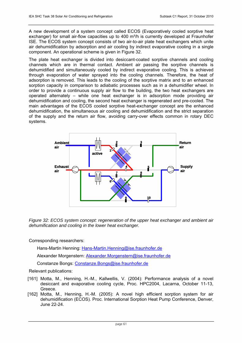
IEA SHC Task 38 Solar Air Conditioning and Refrigeration Subtask C1 Report, 31 October 2010
page 61
A new development of a system concept called ECOS (Evaporatively cooled sorptive heat exchanger) for small air-flow capacities up to 400 m³/h is currently developed at Fraunhofer ISE. The ECOS system concept consists of two air-to-air plate heat exchangers which unite air dehumidification by adsorption and air cooling by indirect evaporative cooling in a single component. An operational scheme is given in Figure 32.
The plate heat exchanger is divided into desiccant-coated sorptive channels and cooling channels which are in thermal contact. Ambient air passing the sorptive channels is dehumidified and simultaneously cooled by indirect evaporative cooling. This is achieved through evaporation of water sprayed into the cooling channels. Therefore, the heat of adsorption is removed. This leads to the cooling of the sorptive matrix and to an enhanced sorption capacity in comparison to adiabatic processes such as in a dehumidifier wheel. In order to provide a continuous supply air flow to the building, the two heat exchangers are operated alternately – while one heat exchanger is in adsorption mode providing air dehumidification and cooling, the second heat exchanger is regenerated and pre-cooled. The main advantages of the ECOS cooled sorptive heat-exchanger concept are the enhanced dehumidification, the simultaneous air cooling and dehumidification and the strict separation of the supply and the return air flow, avoiding carry-over effects common in rotary DEC systems.
Figure 32: ECOS system concept: regeneration of the upper heat exchanger and ambient air dehumification and cooling in the lower heat exchanger.
Corresponding researchers:
Hans-Martin Henning: [email protected]
Alexander Morgenstern: [email protected]
Constanze Bongs: [email protected]
Relevant publications:
[161] Motta, M., Henning, H.-M., Kallwellis, V. (2004): Performance analysis of a novel desiccant and evaporative cooling cycle, Proc. HPC2004, Lacarna, October 11-13, Greece.
[162] Motta, M., Henning, H.-M. (2005): A novel high efficient sorption system for air dehumidification (ECOS). Proc. International Sorption Heat Pump Conference, Denver, June 22-24.
1
2 3
4 5
7 8
9 10
6
Ambientair
Exhaustair
Supplyair
Returnair
active1
2 3
4 5
7 8
9 10
6
Ambientair
Exhaustair
Supplyair
Returnair
active

IEA SHC Task 38 Solar Air Conditioning and Refrigeration Subtask C1 Report, 31 October 2010
page 62
[163] Motta M., Henning, H.-M. (2006) : An Advanced Solar assisted sorption cycle for building air-conditioning: the ECOS potential and performance assessment, Proc. Eurosun 2006, Glasgow, June 27-39.
[164] Henning, H.-M. (2007): Solar assisted air-conditioning of buildings – an overview, Applied Thermal Engineering 27 (2007) 1734 – 1749.
[165] Morgenstern, A., Bongs, C., Henning, H.-M. (2007): ECOS- Ein neues, hocheffizientes Verfahren zur sorptiven Luftentfeuchtung im Vergleich mit sorptionsgestützten Klimatisierungsanlagen in Rotorbauweise. Proc. OTTI Solarenergie, Kloster Banz, Germany, April 23-25.
[166] Bongs, C., Henning, H.-M., Morgenstern, A. (2008): Modelling and exergetic assessment of a sorptive heat exchanger for the application in a novel desiccant evaporative cooling cycle. Proc. EuroSun 2008, Lisbon, October 7-10, Portugal.
[167] Bongs, C., Morgenstern, A., Henning, H.-M. (2009): Evaluation of Sorption Materials for the Application in an Evaporatively Cooled Sorptive Heat Exchanger, Proc. HPC2009, Berlin, September 7-9.
[168] Morgenstern, A., Bongs, C., Wagner, C., Henning, H.-M. (2009): Experimental evaluation of a sorptive-coated heat exchanger prototype for dehumidification purposes, Proc. OTTI Solar Air Conditioning, Palermo, September 30- October 2.
ZAE Bayern Research: An open adsorption system using Zeolite was installed for the air-conditioning of a Jazz Club in Munich/Germany. The system was used as a thermal driven chiller and a thermal energy storage system simultaneously. The thermal COP reached was about 0.85. The open system reduced room temperature and humidity at the same time. Corresponding researcher:
Dr. Andreas Hauer, [email protected]
Relevant publications [169] Hauer, Thermal Energy Storage with Zeolite for Heating and Cooling, Proceedings of
the 7th International Sorption Heat Pump Conference ISHPC ´02, Shanghai, China, 24.-27. September 2002.
Italy Polimi: Politechnico di Milano Research: Polimi is carrying on research in rotor based desiccant cooling. Both experimental and modelling activities are ongoing. One demonstrative AHU of 5,000 m3/h driven by CHCP is installed and monitored in the laboratory. Corresponding researchers:
Mario Motta – [email protected] Marcello Aprile – [email protected] Lorenzo Pistocchini – [email protected]
DREAM Research: Research activities at DREAM on desiccant cooling systems are focused on simulation in TRNSYS and SIMULINK environment and monitoring of a real desiccant cooling system. Main development and results of the experimental work are related to the detailed characterization of single components as well as the whole system in terms of energy performance and reliability, the control strategy, the heat rejection in coupling with conventional cooling machine and the calibration of the simulation models.

IEA SHC Task 38 Solar Air Conditioning and Refrigeration Subtask C1 Report, 31 October 2010
page 63
Corresponding researchers: Pietro Finocchiaro [email protected] Bettina Nocke [email protected] Marco Beccali [email protected]
Relevant publications [170] Beccali M., Finocchiaro P., Sorce M. – “Optimisation of Solar Desiccant Cooling
Systems for applications in the Mediterranean Climate: design and control issues” - International Conference Solar Air-Conditioning – OTTI Kloster Banz - 05.10.2005
[171] Beccali M., Finocchiaro P., Nocke B. – “Solar desiccant cooling systems with hybrid Air-PV solar collectors for applications in the Mediterranean climate” - 61st ATI National Congress – International Session “Solar Heating and Cooling” – pagg. 75-79 - Perugia 14.09.2006
[172] Beccali M., Finocchiaro P., Nocke B., Gioria S., “Solar desiccant cooling AHU coupled with chilled ceiling: description of a new installation at DREAM in Palermo”, Proceedings of the OTTI Conference Solar Air Conditioning, Tarragona (E), October 18th -19th., 2007, pp 389-394, ISBN 978-3-934681-61-3
[173] Beccali M., Finocchiaro P.; Luna M, Nocke B. “Un impianto di Solar Desiccant Cooling a Palermo. Programma di ricerca e primi risultati sperimentali”, Convegno AICARR Padova “Riduzione dei fabbisogni, recupero di efficienza e fonti rinnovabili per il risparmio energetico nel settore residenziale”, 5 Giugno 2008
[174] Beccali M, Finocchiaro P., Luna M, Nocke B. “Monitoraggio di un impianto di solar desiccant cooling a Palermo. Primi risultati e progetto dei test”. 63° Convegno ATI. Palermo, 23-26 Settembre 2008, pp. 07.024
[175] Beccali M., Finocchiaro P., Luna M., Nocke B. “Monitoring of a solar desiccant cooling system in Palermo (Italy). First results and test planning”. Intern. Conference EUROSUN 2008. Lisbona. 7-10 Oct 2008. (pp. 316-317).
[176] Beccali M., Finocchiaro P., Nocke B. “Energy and economic assessment of desiccant cooling systems coupled with single glazed air and hybrid PV/thermal solar collectors for applications in hot and humid climate” Solar Energy Elsevier 2009
DEC system with wet heat exchanger (contributed by Pietro Finocchiaro, DREAM, University of Palermo)
With the aim to increase the cooling effect due to water evaporation in the return air flow rate, standards DEC configuration can be modified replacing the heat recovery wheel (sensible heat exchanger) with one or more plate heat exchangers in series with continuous humidification of the secondary flow.
The wet heat exchanger used is similar to a closed loop wet cooling tower and consists of a cross flow flat plate heat exchanger, spray nozzles, basin and recirculation pump. Spray nozzles used operate with low water pressure and do not require special maintenance.
In the following figure a two-stage system is presented. In the configuration shown, return air is humidified in two steps and leaves the AHU after the heat exchange with supply air stream. In addition, desiccant wheel is regenerated by external air, which is heated before by the two heating coils. This means an additional fan, but at the same time, regeneration air flow can be reduced and no bypass is used (see following scheme). The exclusion of the by-pass across the desiccant rotor and the use of outside air for regenerating the desiccant rotor, can improve performances of the system also in terms of thermal COP and reduction on electricity consumption for the regeneration.
First experimental investigations confirm good performances of the system equipped with wet heat exchangers. Thanks to the optimization of the indirect evaporative cooling process, the contribution of auxiliary cooling coils can strongly reduced.

IEA SHC Task 38 Solar Air Conditioning and Refrigeration Subtask C1 Report, 31 October 2010
page 64
Furthermore, the use of the plate heat exchanger eliminate the moisture carryover that can occur in the rotative heat exchanger normally used in DEC systems.
The risk of fouling (limescale) in the wet heat exchangers has to be taken in consideration during the design phase.

IEA SHC Task 38 Solar Air Conditioning and Refrigeration Subtask C1 Report, 31 October 2010
page 65
6 Thermo-mechanical chillers
Klaus Ellehauge (Ellehauge and Kildermoos, Denmark)
6.1 Brief description of the technology Thermo-mechanical chillers are mechanically driven heat-pumps where the mechanical driving forces are provided by conversion of low temperature heat to mechanical energy.
The idea of providing cooling by combining a mechanical heat pump with a machine for conversion of low temperature heat to mechanical power has only been tried by very few companies. To be successful it would seem desirable to integrate the mechanical structure and the thermodynamics of the two processes.
Of course in separate processes, the mechanical driven heat pump is a well known technology, while the applicable technology for the conversion of low temperature heat, e.g from a solar collector, to mechanical power is not so well developed.
This technology is available only from a small number of larger companies, while a larger amount of smaller companies are researching the technology.
The conversion of thermal power to mechanical power follows the Rankine cycle. In order to keep the driving temperatures low it is most common to operate the Rankine machine with an organic liquid as the working fluid. The technology making use of organic Rankine cycles is often referred to as ORC technology. The temperature ranges in which the ORC machines run efficiently are however not low enough to fully suit low temperature solar collectors.
However a Danish system under development that uses water at low pressure, operates at temperatures suited for solar collectors and provides cooling as well.

IEA SHC Task 38 Solar Air Conditioning and Refrigeration Subtask C1 Report, 31 October 2010
page 66
6.2 Companies on the market
6.2.1 Designs based on the combined use of solar thermal and thermo-mechanical cooling
AC-Sun: AC-Sun is a Danish company developing a turbo/expander, which works with water as a process agent at low pressure and temperatures, and which is driven by thermal solar panels. The conventional thermal solar collector produces low temperature steam on vacuum.
Figure 33: Principle sketch of AC-Sun
The plant is a closed self-contained unit, and only needs to be connected to the thermal solar collector, which consists of a traditional thermal solar panel using water with temperatures between 75-95˚C. District heating or waste heat can also be used as a heat source in the same temperature range. An expander, based on a Rankine process, uses the energy from solar panels to operate a compressor, which through a Carnot process cools air in traditional air coolers.
In the expander (turbine) the energy of the steam is converted into rotational energy which drives the compressor on the same shaft. The compressor - maintaining a vacuum in the cooling circuit - allows for the water to boil at low temperature and low pressure. As the water boils and evaporates, energy is absorbed. This energy is delivered by the circulating air in the air cooler, whereby the temperature in the surrounding areas is lowered.
The steam produced in the cooling process and the solar collector is finally condensed in two air cooled condensers. Electrical power consumption for driving the fans for air distribution and the small water pumps is only 10% of normal AC consumption.
AC-Sun, design basis:
For industrial air-conditioning plants for the Mediterranean area, the following conditions are assumed: an inlet temperature of 17°C and an outdoor temperature of 35°C. These are kept in the upcoming turbine construction with or without water supply.
The design capacity is based on:
Outdoor air temperature 35˚C (Range 25 - 40˚C)

IEA SHC Task 38 Solar Air Conditioning and Refrigeration Subtask C1 Report, 31 October 2010
page 67
Solar collector temperature 85˚C (Range 80 - 100˚C)
Air inlet temperature 17˚C
Solar collector capacity 12 kW (set to 12 m 2 , Equator)
Cooling capacity 10 kW
Power consumption 0.4 kW
Contact & further information: www.ac-sun.com
6.2.2 Designs using ORC in the thermo-mechanical cooling process.
Turboden Turboden is an Italian based company specialized in the applications of Organic Rankine Cycle technology.
Main applications of the products of the company are stated as follows:
• Biomass cogeneration for district-heating or for sawmills and pellet manufacturing companies;
• Waste heat recovery: electric energy production from exhaust streams in industrial processes;
• Small combined cycles: electric energy production from residual heat of internal combustion engines, or gas turbines;
• Geothermal: mainly from low-temperature liquid-dominated wells (100-180 °C); • Solar thermodynamic conversion: electric energy production from medium high
temperature solar collectors.
Turboden ORC units are typically in the size of 2-10 MW (thermal input) and giving an electric power output with an efficiency around 20%.
Turboden units are chosen for the purpose and operate mainly with the following temperatures.
Biomass based cogeneration systems:
310/250°C (high temperature loop) 250/130°C (low temperature loop)
Plant in heat recovery process:
260/150°C
High efficiency units:
310/220°C (high temperature loop) 220/95°C (low temperature loop)
Website and contact: www.turboden.eu
Ormat Technologies, Inc. Ormat Technologies, Inc, is based in USA and claims to be the world leader in Organic Rankine Cycle (ORC) power systems. Most of Ormat's products and business activities are based on its Ormat Energy Converter (OEC), for the utilization of low and medium temperature heat sources. The OEC is a Closed Cycle Vapor Turbogenerator (CCVT) using an organic motive fluid and operating on the Organic Rankine Cycle (ORC).
Main applications are: Geothermal Power, Recovered Energy, Remote Power Units (heated by a burner)

IEA SHC Task 38 Solar Air Conditioning and Refrigeration Subtask C1 Report, 31 October 2010
page 68
Ormat power plants range from 250 kW to 130 MW.
• Brine temperature: from 95°C (203°F) to 315°C (600°F)
Website and contact: www.ormat.com
Furthermore a number of minor companies delivering ORC technology products exist on the market. Examples are:
LTi ADATURB GmbH (Germany) Plants for usage of energy in exhaust gasses or cooling energy of motors.
Range: 175 – 350 kW (thermal) – 30-60 kW (electricity)
Website and contact: http://adaturb.lt-i.com
6.3 Research and Development The above mentioned larger companies Turboden and Ormat Technologies, Inc. as well as AC-Sun are active on the development side. It is not known which universities and other institutes are active in research.
6.4 Relevant reports and publications (only examples)
[177] Søren Minds and Klaus Ellehauge, The AC-Sun, a new concept for air-conditioning, Eurosun 2008, Lisbon, proceedings http://www.iea-shc.org/publications/downloads/task38-AC-Sun.pdf
[178] A number of papers on ORC are published on the Turboden website:
http://www.turboden.eu/en/downloads/downloads.php
[179] and on the Ormat Technologies, Inc. website: http://www.ormat.com/media_center.php?did=147
[180] Other papers of interest:
GRC Annual Meeting 2005; Reno, NV, USA, Power Production from a Moderate -Temperature Geothermal Resource http://www.yourownpower.com/Power/grc%20paper.pdf

IEA SHC Task 38 Solar Air Conditioning and Refrigeration Subtask C1 Report, 31 October 2010
page 69
7 Steam jet chillers
Clemens Pollerberg (Fraunhofer UMSICHT, Germany)
7.1 Brief description of the technology The Steam Jet Ejector Chiller (SJEC) is a thermo-mechanical chiller for cold generation. A refrigerant boils at a low pressure in the evaporator. The necessary heat of evaporation is provided by the water to be chilled. The vapour refrigerant is then compressed by a steam jet ejector to a higher pressure level and fed into a condenser. The driving energy of the steam jet ejector is supplied by motive steam, which can be generated by solar energy. The motive steam and vapour refrigerant are mixed in the steam jet ejector and both are liquefied in the condenser. The condensation takes place at a higher temperature than the ambient temperature, so that the heat from the condensation process can be rejected to the atmosphere. The condensate from the condenser is fed back to the evaporator and to the motive steam generator. Figure 33 depicts the principle of a solar driven SJEC.
Figure 33: Principle sketch of a solar driven SJEC with water as working fluid and refrigerant.
A SJEC can use water as the working fluid, which is used for generating the motive steam and as a refrigerant. In that case, an open process can be constructed without hydraulic separation between the solar collector and the SJEC or the chilled water network and the SJEC. The evaporator can be designed as a flash evaporator and the condenser as a direct contact condenser, such that both devices are basically vessels. The steam jet ejector consists of a motive steam nozzle, a mixing chamber and a diffuser. Thus the whole solar cooling system is simple in design and a high reliability of operation can be expected.
Besides using water as both a working fluid and a refrigerant, different types of fluid have been discussed too. In particular, halocarbons, hydrocarbons and ammonia have been proposed for solar driven SJECs. The advantage of these proposed fluids is a reduction of the required temperature level of the driving heat, while still allowing adequate COP values to be reached. An overview of the possible types of fluid and an investigation of their applicability in a SJEC is given in [181].
SJECs in the higher cold capacity range are designed as two stage chillers and have several steam jet ejectors. In this case, the delivery rate of the ejectors could be different from each other in order to obtain a capacity control of the chiller by switching steam jet ejectors on/off. New approaches to increasing the efficiency of SJECs focus on the use of multiple ejectors in series and the use of two different types of fluid as working fluid and as refrigerant.

IEA SHC Task 38 Solar Air Conditioning and Refrigeration Subtask C1 Report, 31 October 2010
page 70
7.2 Main characteristics SJECs have a specific operational behaviour. The comparison between the reversible COPrev value and the real COP value of a SJEC points out this special operational behaviour, as shown in Figure 34. For this comparison, the COP is defined as the ratio of the cold energy produced in the evaporator QE to the motive heat energy QM required to operate the steam jet ejector, see equation 1. The reversible COPrev value is calculated according to equation 2 with the motive steam temperature TM (corresponding to the saturated steam pressure), the evaporator temperature TE and the condenser temperature TC. The evaporator temperature is 6 °C.
M
E
QQCOP &
&=
Equation 1
( )( )EC
E
M
CMrev TT
TT
TTCOP−
⋅−
= Equation 2
0
1
2
3
4
0 10 20 30 40Condenser temp. [°C]
COP [-]
Motive steam temp.=120°C, revMotive steam temp.=140°C, revMotive steam temp.=160°C, revMotive steam temp.=180°C, revMotive steam temp.=120°C, realMotive steam temp.=140°C, realMotive steam temp.=160°C, realMotive steam temp.=180°C, real
Evaporator temp. = 6°C
Figure 34: COP value of SJEC, reversible and real machine.
A higher motive steam temperature leads to a higher reversible COPrev value. Furthermore the reversible COPrev increases with decreasing condenser temperature. As a start, the COP value of a SJEC also increases with decreasing condenser temperature, but then remains constant below a certain condenser temperature. The reason for this behaviour is that the flow velocity in the steam jet ejector reaches supersonic speed and the mass flow through the ejector cannot be increased further. The comparison shows also that the motive steam temperature (corresponding to saturated steam pressure) can be reduced when the

IEA SHC Task 38 Solar Air Conditioning and Refrigeration Subtask C1 Report, 31 October 2010
page 71
condenser temperature is low enough as the COP value increases. This correlation is used for the controlling concept of a SJEC and leads to the fact that the COP value of a SJEC depends predominantly on the condenser temperature. Furthermore, the COP value depends on the evaporator temperature as well. Figure 35 shows the influence of the condenser and evaporator temperatures on the COP value of a SJEC.
0
0,5
1
1,5
2
2,5
0 10 20 30 40
Condenser temp. [°C]
COP [-]
Evaporator temp. 7°CEvaporator temp. 13°CEvaporator temp. 17°C
Figure 35: COP value as function of the condenser and evaporator temperature.
The COP value of the SJEC increases as the condenser temperature decreases or as the evaporator temperature increases. The condenser temperature is related to the cooling water temperature. The evaporator temperature is related to the chilled water temperature and may be raised when the cold load is lower. This means that at lower ambient temperatures or at part load the COP value of the SJEC increases. In view of a typical cold load curve for a comfort cooling system, which is characterised by long operation periods at low ambient temperatures and at part load of the system, a good mean COP value of SJEC can be expected.
7.3 Research and development There are many companies producing steam jet ejector chillers for industrial use. This technology is currently used for large continuous flows of chilled water in industrial applications. As it is a well established product, there is no necessity in listing down the companies that manfucture these products in this report.
Until now, it is not known whether any solar driven steam jet chiller has come into the market as yet. However, there have been some test rigs and prototypes developed and tested. In 1966 Kakabaev and Davletov described in [182] a first test rig with a cold capacity of 1 kWth with a total efficiency between 0.11 and 0.22. The motive heat is provided by a parabolic mirror sized 12 m². Freon is used as the working fluid and refrigerant. Huang, Petrenko and Chang describe in [183,184] a solar SJEC combined with flat plate collectors and R-141b as refrigerant. The temperature of the motive heat is 95 °C and the system reaches a total efficiency of 0.22 at a solar irradiation of 700 W/m². In [185] Wolpert and Riffat present a 7 kW test plant for air-conditioning of a hospital in Mexico. Water is used as the working fluid and refrigerant. In [186], a small test rig is described and its operational behaviour investigated. The SJEC has a cold capacity of 1 kWth and is solar thermally driven by a

IEA SHC Task 38 Solar Air Conditioning and Refrigeration Subtask C1 Report, 31 October 2010
page 72
parabolic trough collector with an aperture area of 10.5 m². Based on these results, a first completely automated prototype with a cold capacity of 5 kWth was developed and is presented in [187]. Besides the practical work on solar SJECs, a lot of theoretical work has been done to investigate and to optimise the process, as shown for example in [188,189,190,191,192,193,194,195,196,197,198,199,200]. A more detailed review of solar driven steam jet ejector technologies is given in [201].
Research institutes that are active in this field are (note: list is not complete):
1. Fraunhofer Institute UMSICHT Osterfelder Strasse 3, 46047 Oberhausen, Germany.
Researcher: Clemens Pollerberg
e-mail: [email protected]
2. AEE – Institute for Sustainable Technologies,
Feldgasse 19, 8200 Gleisdorf, Austria
Researcher: D. Jaehnig
e-mail: [email protected]
3. University of Stellenbosch Department of Mechanical and Mechatronic Engineering PO Box x1, Matieland 7602 South Africa
Researcher: A. J. Meyer
e-mail: [email protected]
4. University of Nottingham School of theBuilt Environment NG7 2RD United Kongdom
Researcher: Saffa Riffat
e-mail: [email protected]
5. Université catholique de Louvain UCL Ecole Polytechnique de Louvain, Mechanical Engineering Department, TERM Division Place du Levant 2, B-1348, Louvain-la-Neuve, Belgium
Researcher: A. Hemidi
e-mail: [email protected]
6. Selcuk University – Alaeddin Campus Department of Mechanical Engineering, Falculty of Engineering and Architecture

IEA SHC Task 38 Solar Air Conditioning and Refrigeration Subtask C1 Report, 31 October 2010
page 73
42250 Konya Turkey
Researcher: H. Kursad Ersoy
e-mail: [email protected]
7. National Taiwan University Department of Mechanical Engineering No.1 Roosevelt Rd. Sec 4 Taipei, Taiwan 106 Taiwan
Researcher: Bin-Juine Huang
e-mail: [email protected]
7.4 References
[181] Wimolsiri Pridasawas, Solar-Driven Refrigeration Systems with Focus on the Ejector Cycle, Doctoral Thesis, School of Industrial Engineering and Management – Royal Institute of Technology KTH, Stockholm, 2006.
[182] Kakabaev, A., Davletov, A., A Freon Ejector Solar Cooler, Geliotekhnika, Vol. 2, No. 5, pp. 42-48,. AS Turkmen SSR,1966.
[183] Huang, B.J., Petrenko, V.A., Chang, J.M., Zhuk, K.B., A High-Performance Solar Ejector Cooling System, Department of Mechanical Engineering, National Taiwan University, Taipei, Taiwan/Odessa State Academy of Refrigeration, Odessa, Ukraine, 2000.
[184] Huang, B.J., Petrenko, V.A., A combined Ejector Cooling and hot water supply system using solar and waste heat energy, Department of Mechanical Engineering, National Taiwan University, Taipei, Taiwan/Odessa State Academy of Refrigeration, Odessa, Ukraine, 2000.
[185] Wolpert, J.L., Riffat, S.B., Hybrid Solar/Gas Cooling Ejector Unit for a Hospital in Mexico, http://www.kenes.com/ises.abstracts/Htm/0171.htm, Institute of Building Technology, School of the Built Environment, University of Nottingham, Great Britain, 1999.
[186] Pollerberg, C. Ali, A.H.H., Dötsch, C: Solar driven steam jet ejector, Applied Thermal Engineering 29, pp. 1245–1252, 2009.
[187] Pollerberg C., Jaehnig D., Doetsch C., Prototype of a Solar Driven Steam Jet Ejector Chiller, Proceedings of the 3rd International Conference on Solar Air-Conditioning, Palermo, 30.09- 2.10.09, ISBN 978-3-941758-06-9, 2009.
[188] Anderson, H., Assessment of solar powered Vapor Jet Air-Conditioning Systems, Proc. Int. Solar Energy Congress and Exposition (ISES), UCLA, Los Angeles, Ca, pp. 408-409. USA, 1975.
[189] Zhadan, S., Z., Shchetinina, N., A., Selection of cycle Design Parameters for Solar Ejector Freon Refrigeration Machine (SEFRM), Geliotekhnika, Vol. 16, No.1, pp. 44-47, 1977.
[190] Sokolov, M., Hershgal, D., Solar-Powered Compression-enhanced Ejector Air Conditioner, Solar Energy Vol. 51, No. 6, pp. 183-194, 1993.
[191] Petrenko, V., A., Bulavin, I., V., Samofatov, I., YA., Investigation of the Methods increasing the efficiency of solar ejector cooling and refrigeration systems, Department of Mechanical Engineering, National Taiwan University, Taipei, Taiwan/Odessa State Academy of Refrigeration, Odessa, Ukraine, 2000.
[192] Vidal, H., Colle, S., Pereira, G. dos S., Modelling and hourly simulation of a solar ejector cooling system, Applied Thermal Engineering 26, pp. 663-672, 2006.

IEA SHC Task 38 Solar Air Conditioning and Refrigeration Subtask C1 Report, 31 October 2010
page 74
[193] Riffat, S., et al., Study of a gas-liquid ejector and its application to a solar-powered bi-ejector refrigeration system, Applied Thermal Engineering, Vol. 25, pp. 2891-2902, 2005.
[194] Khattab, N.M., Barakat, M.H., Modelling the design and performance characteristics of solar steam-jet cooling for comfort air conditioning, Solar Energy, Vol. 73, pp. 257-267, 2002.
[195] Hemidi, A., et al., Designing and Rating a Tritherm Solar Ejector System for Residential Cooling, Proceedings of the EUROSUN 2008, 1st International Conference on Solar Heating, Cooling and Buildings, 7th to 10th October Lisbon – Portugal, ISBN 978-972-95854-7-0, 2008.
[196] Ersoy, H.K., et al., Performance of a solar ejector cooling-system in the southern region of Turkey, Applied Energy, Vol. 84, pp. 971-983, 2007.
[197] Colle, S., et al., On the validity of a design method for a solar-assisted ejector cooling system, Solar Energy, Vol. 83, pp. 139-149, 2009.
[198] Vidal, H., et al., Modelling and hourly simulation of a solar ejector cooling system, Applied Thermal Engineering, Vol. 26, pp. 663-672, 2006.
[199] Guo, J., Shen, H.G., Modelling solar-driven ejector refrigeration system offering air conditioning for office buildings, Energy and Building, Vol. 41, pp. 175-181, 2009.
[200] Alexis, G.K., Karayiannis, E.K., A solar ejector cooling system using refrigerant R134a in the Athens area, Renewable Energy, Vol. 30, pp. 1457-1469, 2005.
[201] Abdulateef, J.M., Alghoul, M.A., et al., Review on solar-driven ejector refrigeration technologies, Renewable and Sustainable Energy Review, Vol. 13, pp. 1338-1349, 2009.

IEA SHC Task 38 Solar Air Conditioning and Refrigeration Subtask C1 Report, 31 October 2010
page 75
Appendix 1 Contact details of contributors Name: Michael Krause Institution: Fraunhofer Institute of Building Physics, Energy Systems Address: Gottschalkstr. 28a 34125 Kassel, Germany e-mail: [email protected] Name: Robert Ghirlando Institution: Faculty of Engineering
University of Malta Address: Msida Malta e-mail: [email protected] Name: Erich Podesser Institution: AEE-INTEC Address: Feldgasse 19
A-8200 Gleisdorf, Austria
e-mail: [email protected] Name: Tomas Núñez Institution: Fraunhofer Institute of Solar Energy Address: Heidenhofstr. 2 79110 Freiburg Germany e-mail: [email protected] Name: Mustafa Jaradat Institution: Kassel University, Solar and Systems Engineering Address: Kurt-Wolters-Str. 3, 34125 Kassel Germany e-mail: [email protected] Name: Roland Heinzen Institution: Kassel University, Solar and Systems Engineering Address: Kurt-Wolters-Str. 3, 34125 Kassel Germany e-mail: [email protected] Name: Lucio Mesquita Institution: Enerworks Inc., Applications Engineering Address: 252, Hamilton Crescent Dorchester Canada e-mail: [email protected] Name: Paul Bourdoukan Institution: LOCIE-INES/CNRS Address: LOCIE FRE CNRS 3220 Université de Savoie Institut National de l'Energie Solaire Parc technologique de Savoie Technolac 50 av. Lac Léman - BP 332 F-73377 Le Bourget du Lac CEDEX France email: [email protected]

IEA SHC Task 38 Solar Air Conditioning and Refrigeration Subtask C1 Report, 31 October 2010
page 76
Name: Etienne Wurtz Institution LOCIE-INES/CNRS Address: LOCIE FRE CNRS 3220 Université de Savoie Institut National de l'Energie Solaire Parc technologique de Savoie Technolac 50 av. Lac Léman - BP 332 F-73377 Le Bourget du Lac CEDEX France e-mail [email protected]
Name: Klaus Ellehauge Institution: Ellehauge and Kildermoos Address: Vestergade 48H, 2.tv.
8000 Århus C Denmark
e-mail: [email protected] Name: Constanze Bongs Institution: Fraunhofer Institute of Solar Energy Address: Heidenhofstr. 2 79110 Freiburg Germany e-mail: [email protected] Name: Clemens Pollerberg Insitution: Fraunhofer Institute UMSICHT Address: Osterfelder Strasse 3,
46047 Oberhausen, Germany.
e-mail: [email protected] Name: Pietro Finocchiaro Institution: Universita Degli Studi di Palermo Dipartimento di Ricerche Energetiche ed Ambientali Address: Viale delle Scienze 90128 Palermo, Italy e-mail: [email protected] Name: Marcelo Izquierdo Millán (M. Izquierdo) Institution: Instituto de Ciencias de la Construcción Eduardo Torroja (CSIC) Address: C/ Serrano Galvache, 4, 28033 Madrid, Spain e-mail: [email protected]
Name: José Daniel Marcos del Cano Institution: Escuela Técnica Superior de Ingenieros Industriales (UNED) Address: C/ Juan del Rosal 8, 28040 Madrid, Spain e-mail: [email protected]

IEA SHC Task 38 Solar Air Conditioning and Refrigeration Subtask C1 Report, 31 October 2010
page 77