taperloc hip - surgitech
TRANSCRIPT

Taperloc Hip Surgical Technique
Disclaimer
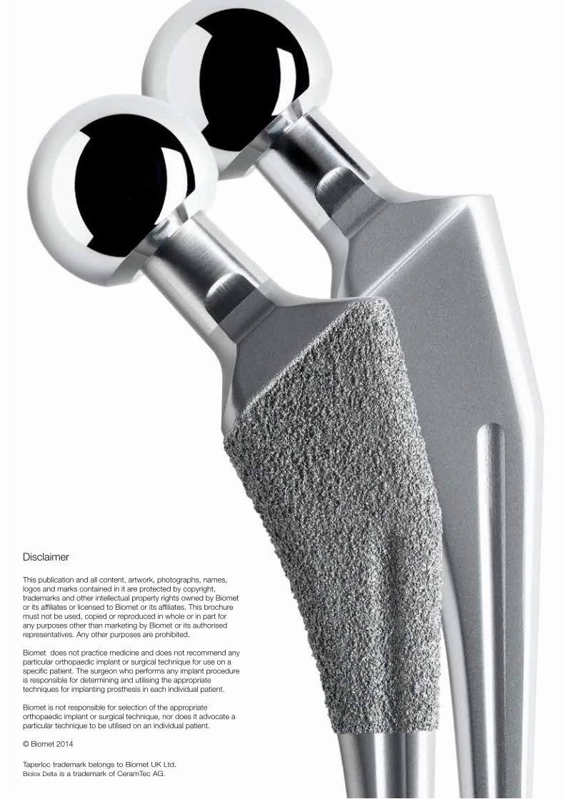
This publication and all content, artwork, photographs, names, logos and marks contained in it are protected by copyright, trademarks and other intellectual property rights owned by Biomet or its affiliates or licensed to Biomet or its affiliates. This brochure must not be used, copied or reproduced in whole or in part for any purposes other than marketing by Biomet or its authorised representatives. Any other purposes are prohibited.
Biomet does not practice medicine and does not recommend any particular orthopaedic implant or surgical technique for use on a specific patient. The surgeon who performs any implant procedure is responsible for determining and utilising the appropriate techniques for implanting prosthesis in each individual patient.
Biomet is not responsible for selection of the appropriate orthopaedic implant or surgical technique, nor does it advocate a particular technique to be utilised on an individual patient.
© Biomet 2014
Taperloc trademark belongs to Biomet UK Ltd. Biolox Delta is a trademark of CeramTec AG.

Taperloc Hip Surgical Technique

5
1. Pre-operative planning
Selection of the correct femoral component is
attained through careful pre-operative planning.
This can be achieved manually by means of x-ray
templates, or digitally by means of a PACS system.
Manual pre-operative planning
The Taperloc Hip provides a comprehensive
selection of femoral x-ray templates in 110%, 115%
and 120% magnification.
These templates are positioned over the AP and
Lateral x-rays to best decide the correct implant
size, modular head neck length and whether a
standard or lateralised Taperloc® stem is required to
restore the patient’s natural anatomy.
Digital pre-operative planning
The Taperloc Hip digital templates are available
through various digital template providers. When
using digital templating for a primary THR, it is
necessary to use a magnification marker with a
known dimension. This is required in order for the
system to calculate the correct magnification.
As soon as the correct magnification has been
determined, the system can be used to best decide
the correct implant size, modular head neck length
and whether a standard or lateralised Taperloc stem
is required to restore the patient’s natural anatomy.

6
2. Surgical exposure
The Taperloc femoral component can be implanted
using any of the standard approaches for total hip
replacement. The aim of the approach selected
is to provide adequate visualisation of both the
acetabulum and proximal femur.
3. Femoral neck osteotomy
Once the femoral head has been dislocated from
the acetabulum, the femoral neck resection can be
completed using the femoral resection template.
(Figure 3 & 4)
figure 3 figure 4

7
4. Preparation of the acetabulum and insertion of acetabular component
When complete visualization of the acetabulum
is achieved, preparation of the acetabulum and
acetabular component insertion must be carried out
as instructed in the appropriate operative technique.
5. Preparation of the femur
To help avoid undersizing, varus positioning and to
allow for correct alignment of the reamer and broach,
it may be necessary to remove a small section of the
medial cortex from the greater trochanter.
This can be achieved by one of two methods. The
first involves the use of the special box chisel (Figure
5), or by using the starter drill and intramedullary
reamer (Figures 6 & 7). Whatever technique is
employed, the aim is to provide a lateral starting
point for the intra-medullary reamer and broaches.
figure 5
figure 6 figure 7

8
5a. Reaming the distal femur
Once the femoral canal has been located, ream the
intramedullary canal with the tapered reamer. (Figure 8)
Reaming should not be carried out using power tools.
5b. Broaching the proximal femur
Starting with the smallest broach available, attach the
broach to the broach handle as shown (Figure 9) and
begin preparing the proximal femur (Figure 10). It is
important to ensure the broach is orientated so that
the medial/lateral axis of the broach is parallel with
that of the anatomic medial/lateral axis of the femoral
neck, as this will determine the angle of anteversion
for the implanted femoral component. Sequentially
larger broaches are then used until either complete
stability is achieved, or the stem size selected during
pre-operative planning has been reached. The angled
surface of the femoral broach should then be level with
the resected femoral neck. (Figure 11) If the femoral
broach has finished below the level of the resected
calcar, a calcar trimmer can then used to plane the
calcar flush with the angled surface of the broach.
(Figure 12)
figure 8
figure 9
figure 10 figure 11 figure 12
9
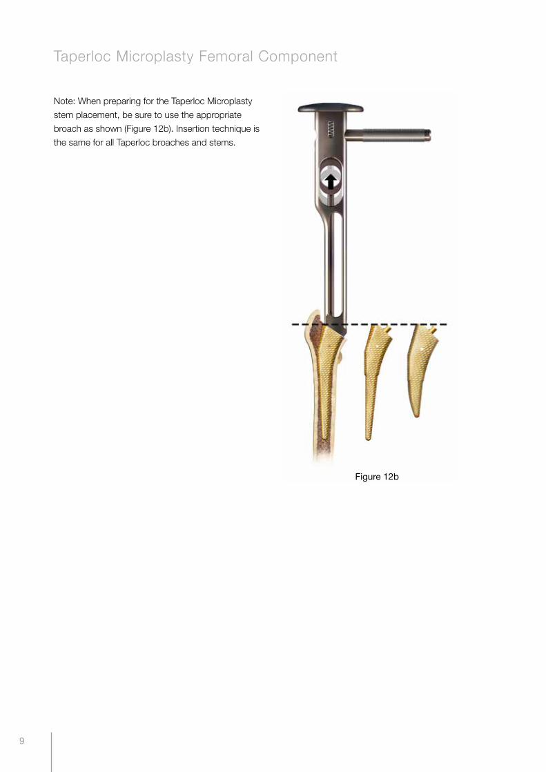
Note: When preparing for the Taperloc Microplasty
stem placement, be sure to use the appropriate
broach as shown (Figure 12b). Insertion technique is
the same for all Taperloc broaches and stems.
Figure 12b
Taperloc Microplasty Femoral Component

10
6. Trial reduction - Broach
For cementless and cemented implants the
final broach used corresponds with the femoral
component to be implanted. (i.e. 12.5mm broach =
12.5mm implant)
With the final broach in position, the trial neck can be
attached. (Figure 13) The desired trial modular head
is then attached to the trial neck and the hip joint
reduced. The joint is then assessed for joint stability
and leg length. Trial modular heads are available in
numerous offsets to facilitate a stable joint. However,
should it not be possible attain joint stability without
over increasing the leg length, the trial neck is
removed and the lateralised version of the trial
neck is attached to the broach. The trial reduction
procedure is repeated until joint stability and the
desired leg length has been achieved. (Figure 14 &
15)
Once the trial reduction has been completed,
carefully remove the trial modular head and trial
neck from the broach. The broach handle is then re-
attached to the broach and the complete assembly
carefully removed from the femur to avoid enlarging
the prepared canal. To promote the in-growth of
bone into the porous coating, irrigation and drying of
the femoral canal is not recommended.
figure 13
figure 14
figure 15
Standard offset Lateralised offset
(Standard +6mm)

11
7. Femoral component insertion – Cementless
When implanting a cementless implant, the definitive
implant is equivalent to the last broach used. (ie.
12.5mm broach = 12.5mm implant)
Select the desired stem and attach it to the inserter
handle. (Figure 16) The stem is then impacted until
the edge of the porous coating is aligned with the rim
of the planed calcar. (Figure 17) The inserter handle is
then removed.
figure 16
figure 17
12
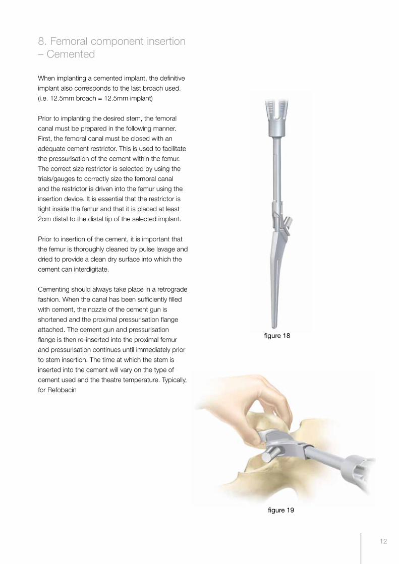
8. Femoral component insertion – Cemented
When implanting a cemented implant, the definitive
implant also corresponds to the last broach used.
(i.e. 12.5mm broach = 12.5mm implant)
Prior to implanting the desired stem, the femoral
canal must be prepared in the following manner.
First, the femoral canal must be closed with an
adequate cement restrictor. This is used to facilitate
the pressurisation of the cement within the femur.
The correct size restrictor is selected by using the
trials/gauges to correctly size the femoral canal
and the restrictor is driven into the femur using the
insertion device. It is essential that the restrictor is
tight inside the femur and that it is placed at least
2cm distal to the distal tip of the selected implant.
Prior to insertion of the cement, it is important that
the femur is thoroughly cleaned by pulse lavage and
dried to provide a clean dry surface into which the
cement can interdigitate.
Cementing should always take place in a retrograde
fashion. When the canal has been sufficiently filled
with cement, the nozzle of the cement gun is
shortened and the proximal pressurisation flange
attached. The cement gun and pressurisation
flange is then re-inserted into the proximal femur
and pressurisation continues until immediately prior
to stem insertion. The time at which the stem is
inserted into the cement will vary on the type of
cement used and the theatre temperature. Typically,
for Refobacin
figure 18
figure 19

13
+R bone cement with a theatre temperature of 21°C
mixed in the OptiVac cement-mixing system, the
stem can be introduced 4 - 5 minutes after mixing
has commenced.
Select the desired stem and attach it to the
inserter handle as shown. (Figure 18) The stem is
then inserted down the centre of the canal in one
continuous movement. During insertion of the stem,
pressure must be maintained within the canal by
sealing or closing the medial calcar. (Figure 19)
Pressure is then maintained on the stem through the
inserter handle until the cement has polymerised.
figure 20
figure 21
figure 22

14
9. Trial reduction - Implant
If desired, a further trial reduction can be completed
after the implantation of the femoral stem and prior
to placement of the modular head onto the taper.
(Figure 20) This is important because the femoral
component may not in every instance seat exactly
to the same depth as the broach and planed calcar.
If this is the case, then it is recommended that a
further trial reduction is carried out.
10. Modular head impaction
The selected modular head is positioned on the
clean male taper of the femoral stem with hand
pressure only. Alternatively, a combination of hand
pressure and a twisting motion can be used. The
modular head is finally seated in position by means
of a gentle tap utilising the femoral head impaction
device and mallet. (Figure 21)
Modular heads should never be heavily impacted
onto the trunnion as this may cause damage to
highly polished surface of the modular head.
Once the correct modular femoral head has been
attached to the femoral component, the hip joint can
be reduced. (Figure 22)
figure 23
figure 24

15
Neck Length
ABT CoCrMoM2A & UHMWPE
ABT CeramicBiolox Delta Ceramic
28mm 32mm 36mm 28mm 32mm 36mm
-6mm 650-0863 650-0870 650-0839 - -
-3mm 650-0864 650-0871 650-0840 164135 164185 650-0660
0mm 650-0865 650-0872 650-0841 164136 164186 650-0661
+3mm 650-0866 650-0873 650-0842 164137 164187 650-0662
+6mm 650-0867 650-0874 650-0843 - 12-115117 650-0663
Stem Diameter
mm
Stem Length
mm
Cementless Cemented
Porous Coated Porous & HA Coated Porous & BoneMaster® CoCrMo
Standard Lateralised Standard Lateralised Standard Lateralised StandardLateral-
ised
6.0 132 103201 11-103201 21-103201 21-123201 103201BM 11-130201BM - -
7.5 135 164400 103807 21-103202 21-123202 103202BM 11-130202BM 650-0325 650-0331
9.0 137 103203 11-103203 21-103203 21-123203 103203BM 11-130203BM - -
10.0 140 164401 103808 21-103204 21-123204 103204BM 11-130204BM 650-0326 650-0332
11.0 142 103205 11-103205 21-103205 21-123205 103205BM 11-130205BM - -
12.5 145 164402 103809 21-103206 21-123206 103206BM 11-130206BM 650-0327 650-0333
13.5 147 103207 11-103207 21-103207 21-123207 103207BM 11-130207BM - -
15.0 150 164403 103810 21-103208 21-123208 103208BM 11-130208BM 650-0328 650-0334
17.5 155 164404 103811 21-103209 21-123209 103209BM 11-130209BM 650-0329 650-0335
20.0 160 164405 103812 21-103210 21-123210 103210BM 11-130210BM 650-0330 650-0336
Ordering information
Taperloc Femoral Components - Type 1 Taper
Modular Femoral Head Components - Type 1 Taper (T1)
Catalogue Number
Description
31-600064 Taperloc Haptic General Instr Tray
31-600065 Taperloc Haptic Rasp Tray
31-600005 Modular Stem & Head Removal Tray
31-600066 Taperloc Haptic 28 & 32mm Trial Modular Head Tray Insert Complete (T1)
31-600432 Taperloc X-Ray Templates (T1)
31-601128 ABT Trial Modular Head Tray Insert Complete 22.2, 28, 32 & 36mm (T1)
Taperloc Femoral Instrumentation for Primary Components - Type 1 Taper (T1)
Taperloc Trial Head Tray Insert (T1)
Biomet Femoral Head and Stem Removal Instrument Tray
Taperloc Haptic General Instrument Tray
Taperloc Haptic Rasp Tray
The modular heads listed above are only suitable for Biomet Femoral Components with Biomet Type1 Taper(T1).

16
Stem Diam-etermm
Stem Length
mm
Cementless Cemented
Porous Coated Porous & HA Coated Porous & BoneMaster® CoCrMo
Standard Lateralised Standard Lateralised Standard Lateralised Standard Lateralised
6.0 132 650-0580 650-0590 650-0550 650-0560 650-0550BM 650-0560BM - -
7.5 135 650-0319 650-0349 650-0551 650-0561 650-0551BM 650-0561BM 650-0337 650-0343
9.0 137 650-0260 650-0263 650-0552 650-0562 650-0552BM 650-0562BM - -
10.0 140 650-0320 650-0350 650-0553 650-0563 650-0553BM 650-0563BM 650-0338 650-0344
11.0 142 650-0261 650-0264 650-0554 650-0564 650-0554BM 650-0564BM - -
12.5 145 650-0321 650-0351 650-0555 650-0565 650-0555BM 650-0565BM 650-0339 650-0345
13.5 147 650-0262 650-0265 650-0556 650-0566 650-0556BM 650-0566BM - -
15.0 150 650-0322 650-0352 650-0557 650-0567 650-0557BM 650-0567BM 650-0340 650-0346
17.5 155 650-0323 650-0353 650-0558 650-0568 650-0558BM 650-0568BM 650-0341 650-0347
20.0 160 650-0324 650-0354 650-0559 650-0569 650-0559BM 650-0569BM 650-0342 650-0348
Taperloc Femoral Components - 12/14 Taper (12/14)
Taperloc Trial Head Tray Insert
(12/14)
Taperloc Haptic General Instrument Tray
Taperloc Haptic Rasp TrayBiomet Femoral Head and Stem Removal Instrument Tray
Catalogue Number
Description
31-600064 Taperloc Haptic General Instr Tray
31-600065 Taperloc Haptic Rasp Tray
31-600005 Modular Stem & Head Removal Tray
31-600068 Taperloc Haptic 28 & 32mm Trial Modular Head Tray Insert Complete (12/14)
31-100377 Taperloc X-Ray Templates (12/14)
31-601130 ABT Trial Modular Head Tray Insert Complete 22.2, 28, 32 & 36mm (12/14)
Taperloc Femoral Instrumentation for Primary Components - 12/14 Taper (12/14)
Neck Length
ABT CoCrMoM2A & UHMWPE
ABT CeramicBiolox Delta Ceramic
28mm 32mm 36mm 28mm 32mm 36mm
-4mm - 650-0882 650-0887 - 650-0833 650-0836
-3.5mm 650-0877 - - 650-0830 - -
0mm 650-0878 650-0883 650-0888 - 650-0834 650-0837
+3.5mm 650-0879 - - 650-0832 - -
+4mm - 650-0884 650-0889 - 650-0835 650-0838
+8mm - - 650-0890 - - 650-0667
Modular Femoral Head Components - 12/14 Taper (12/14)
17
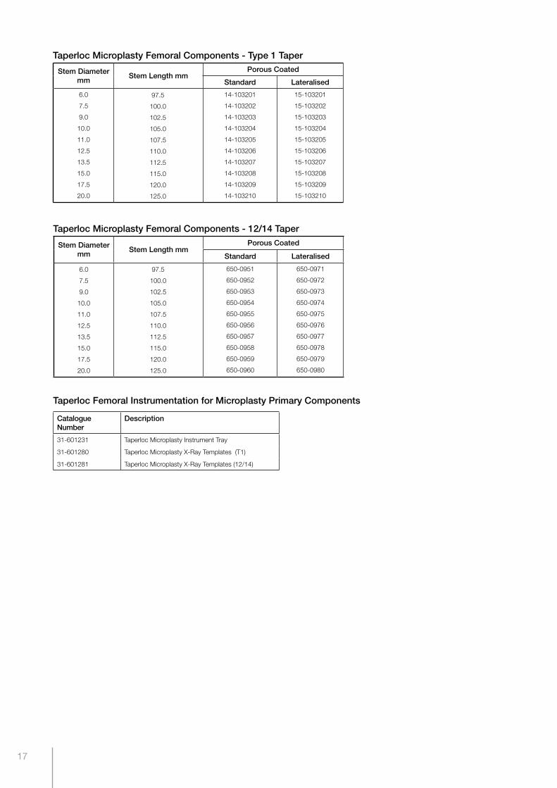
Taperloc Microplasty Femoral Components - Type 1 Taper
Stem Diametermm
Stem Length mmPorous Coated
Standard Lateralised
6.0
7.5
9.0
10.0
11.0
12.5
13.5
15.0
17.5
20.0
97.5
100.0
102.5
105.0
107.5
110.0
112.5
115.0
120.0
125.0
14-103201
14-103202
14-103203
14-103204
14-103205
14-103206
14-103207
14-103208
14-103209
14-103210
15-103201
15-103202
15-103203
15-103204
15-103205
15-103206
15-103207
15-103208
15-103209
15-103210
Taperloc Microplasty Femoral Components - 12/14 Taper
Stem Diametermm
Stem Length mmPorous Coated
Standard Lateralised
6.0
7.5
9.0
10.0
11.0
12.5
13.5
15.0
17.5
20.0
97.5
100.0
102.5
105.0
107.5
110.0
112.5
115.0
120.0
125.0
650-0951
650-0952
650-0953
650-0954
650-0955
650-0956
650-0957
650-0958
650-0959
650-0960
650-0971
650-0972
650-0973
650-0974
650-0975
650-0976
650-0977
650-0978
650-0979
650-0980
Catalogue Number
Description
31-601231 Taperloc Microplasty Instrument Tray
31-601280 Taperloc Microplasty X-Ray Templates (T1)
31-601281 Taperloc Microplasty X-Ray Templates (12/14)
Taperloc Femoral Instrumentation for Microplasty Primary Components

18
Notes

19
Notes

20

Legal Manufacturer:Biomet U.K., Ltd. Waterton Industrial Estates, Bridgend, South Wales CF31 3XA, U.K.
www.biomet.com©2014 Biomet Orthopedics • Form No. BMET0889.0-ENG • REV0214