tank inspection, repair, alteration, and reconstruction...
TRANSCRIPT

ttee Tank Inspection, Repair, Alteration,
and Reconstruction
ommi
OnlyAPI STANDARD 653THIRD EDITION, DECEMBER 2001ADDENDUM 1, SEPTEMBER 2003ADDENDUM 2, NOVEMBER 2005ADDENDUM 3, FEBRUARY 2008ERRATA, APRIL 2008
For C Use

For C
ommittee
Use O
nly

ee Tank Inspection, Repair, Alteration, and Reconstruction
ittDownstream Segment
mm nlyAPI STANDARD 653THIRD EDITION, DECEMBER 2001ADDENDUM 1, SEPTEMBER 2003ADDENDUM 2, NOVEMBER 2005ADDENDUM 3, FEBRUARY 2008ERRATA, APRIL 2008
For C
oUse
O

For C
ommittee
Use O
nly
SPECIAL NOTES
API publications necessarily address problems of a general nature. With respect to partic-ular circumstances, local, state, and federal laws and regulations should be reviewed.
Neither API nor any of API's employees, subcontractors, consultants, committees, or other assignees make any warranty or representation, either express or implied, with respect to the accuracy, completeness, or usefulness of the information contained herein, or assume any liability or responsibility for any use, or the results of such use, of any information or process disclosed in this publication. Neither API nor any of API's employees, subcontrac-tors, consultants, or other assignees represent that use of this publication would not infringe upon privately owned rights.
API publications may be used by anyone desiring to do so. Every effort has been made by the Institute to assure the accuracy and reliability of the data contained in them; however, theInstitute makes no representation, warranty, or guarantee in connection with this publication and hereby expressly disclaims any liability or responsibility for loss or damage resulting from its use or for the violation of any authorities having jurisdiction with which this publi-cation may conflict.
API publications are published to facilitate the broad availability of proven, sound engi-neering and operating practices. These publications are not intended to obviate the need for applying sound engineering judgment regarding when and where these publications should be utilized. The formulation and publication of API publications is not intended in any way to inhibit anyone from using any other practices.
Any manufacturer marking equipment or materials in conformance with the marking requirements of an API standard is solely responsible for complying with all the applicable requirements of that standard. API does not represent, warrant, or guarantee that such prod-ucts do in fact conform to the applicable API standard.
05
All rights reserved. No part of this work may be reproduced, stored in a retrieval system, or transmitted by any means, electronic, mechanical, photocopying, recording, or otherwise,
without prior written permission from the publisher. Contact the Publisher, API Publishing Services, 1220 L Street, N.W., Washington, D.C. 20005.
Copyright © 2001, 2003, 2005, 2008 American Petroleum Institute

For C
ommittee
Use O
nly
FOREWORD
This standard is based on the accumulated knowledge and experience of owners, operators, manufacturers, and repairers of steel storage tanks. The object of this publication is to pro-vide guidance in the inspection, repair, alteration, and reconstruction of steel storage tanks used in the petroleum and chemical industries. If tanks are inspected, repaired, altered, or reconstructed in accordance with this stan-dard, the owner/operator may elect to modify, delete, or amplify sections of this standard. It is strongly recommended that such modifications, deletions, or amplifications be made by supplementing this standard rather than by rewriting or incorporating sections into an-other complete standard.
The rules given in this standard are minimum requirements. This standard is not to be interpreted as approving, recommending, or endorsing any specific design nor limiting the methods of inspection, repair, alteration, or reconstruction.
Shall: As used in a standard, “shall” denotes a minimum rquirement in order to conform to the specification.
08 Should: As used in a standard, “should” denotes a recommendation or that which is advised but not required in order to conform to the specification.
Each edition, revision, or addenda to this API standard may be used beginning with the date of issuance shown on the cover page for that edition, revision, or addenda. Each edition, revision, or addenda to this API standard becomes effective six months after the date of issu-ance for equipment that is certified as being rerated, reconstructed, relocated, repaired, mod-ified (altered), inspected, and tested per this standard. During the six-month time between the date of issuance of the edition, revision, or addenda and the effective date, the purchaser and manufacturer shall specify to which edition, revision, or addenda the equipment is to be rated, reconstructed, relocated, repaired, modified (altered), inspected, and tested.
Nothing contained in any API publication is to be construed as granting any right, by implication or otherwise, for the manufacture, sale, or use of any method, apparatus, or prod-uct covered by letters patent. Neither should anything contained in the publication be con-strued as insuring anyone against liability for infringement of letters patent.
This document was produced under API standardization procedures that ensure appropri-ate notification and participation in the developmental process and is designated as an API standard. Questions concerning the interpretation of the content of this publication or com-ments and questions concerning the procedures under which this publication was developed should be 05 directed in writing to the Director of Standards, American Petroleum Institute, 1220 L Street, N.W., Washington, D.C. 20005. Requests for permission to reproduce or translate all or any part of the material published herein should also be addressed to the director.
Generally, API standards are reviewed and revised, reaffirmed, or withdrawn at least every five years. A one-time extension of up to two years may be added to this review cycle. Status of the publication can be ascertained from the API Standards Department, telephone (202) 682-8000. A catalog of API publications and materials is published annually and updated quarterly by API, 1220 L Street, N.W., Washington, D.C. 20005.
Suggested revisions are invited and should be submitted to the Standards and Publications Department, API, 1220 L Street, NW, Washington, DC 20005, [email protected].
iii

For C
ommittee
Use O
nly
NOTICE
INSTRUCTIONS FOR SUBMITTING A PROPOSED REVISION TO THIS STANDARD UNDER CONTINUOUS MAINTENANCE
03This standard is maintained under continuous maintenance procedures by the American Petroleum Institute for which the Standards Department. These procedures establish a docu-mented program for regular publication of addenda or revisions, including timely and docu-mented consensus action on requests for revisions to any part of the standard. Proposed revisions shall be submitted to the Director, Standards Department, American Petroleum Institute, 1220 L Street, NW, Washington, D.C. 20005-4070, [email protected].
iv
F
CONTENTS
Page
05
03
08
03
08
0508
0805
08
05
05
03
05
or Committ
ee
Use O
nly
1 SCOPE . . . . . . . . . . . . . . . . . . . . . . . . . . . . . . . . . . . . . . . . . . . . . . . . . . . . . . . . . . . . . . 1-11.1 Introduction . . . . . . . . . . . . . . . . . . . . . . . . . . . . . . . . . . . . . . . . . . . . . . . . . . . . . 1-11.2 Compliance with this Standard . . . . . . . . . . . . . . . . . . . . . . . . . . . . . . . . . . . . . . 1-11.3 Jurisdiction . . . . . . . . . . . . . . . . . . . . . . . . . . . . . . . . . . . . . . . . . . . . . . . . . . . . . . 1-11.4 Safe Working Practices . . . . . . . . . . . . . . . . . . . . . . . . . . . . . . . . . . . . . . . . . . . . 1-1
2 REFERENCES . . . . . . . . . . . . . . . . . . . . . . . . . . . . . . . . . . . . . . . . . . . . . . . . . . . . . 2-12.1 Referenced Publications . . . . . . . . . . . . . . . . . . . . . . . . . . . . . . . . . . . . . . . . . . . 2-12.2 Other References . . . . . . . . . . . . . . . . . . . . . . . . . . . . . . . . . . . . . . . . . . . . . . . . . 2-1
3 DEFINITIONS. . . . . . . . . . . . . . . . . . . . . . . . . . . . . . . . . . . . . . . . . . . . . . . . . . . . . . . . 3-1
4 SUITABILITY FOR SERVICE . . . . . . . . . . . . . . . . . . . . . . . . . . . . . . . . . . . . . . . . . . 4-14.1 General . . . . . . . . . . . . . . . . . . . . . . . . . . . . . . . . . . . . . . . . . . . . . . . . . . . . . . . . . 4-14.2 Tank Roof Evaluation . . . . . . . . . . . . . . . . . . . . . . . . . . . . . . . . . . . . . . . . . . . . . 4-14.3 Tank Shell Evaluation . . . . . . . . . . . . . . . . . . . . . . . . . . . . . . . . . . . . . . . . . . . . . 4-24.4 Tank Bottom Evaluation . . . . . . . . . . . . . . . . . . . . . . . . . . . . . . . . . . . . . . . . . . . 4-74.5 Tank Foundation Evaluation . . . . . . . . . . . . . . . . . . . . . . . . . . . . . . . . . . . . . . . . 4-9
5 BRITTLE FRACTURE CONSIDERATIONS . . . . . . . . . . . . . . . . . . . . . . . . . . . . . . 5-15.1 General . . . . . . . . . . . . . . . . . . . . . . . . . . . . . . . . . . . . . . . . . . . . . . . . . . . . . . . . . 5-15.2 Basic Considerations . . . . . . . . . . . . . . . . . . . . . . . . . . . . . . . . . . . . . . . . . . . . . . 5-15.3 Assessment Procedure . . . . . . . . . . . . . . . . . . . . . . . . . . . . . . . . . . . . . . . . . . . . . 5-1
6 INSPECTION . . . . . . . . . . . . . . . . . . . . . . . . . . . . . . . . . . . . . . . . . . . . . . . . . . . . . . . . 6-16.1 General . . . . . . . . . . . . . . . . . . . . . . . . . . . . . . . . . . . . . . . . . . . . . . . . . . . . . . . . . 6-16.2 Inspection Frequency Considerations . . . . . . . . . . . . . . . . . . . . . . . . . . . . . . . . . 6-16.3 Inspections from the Outside of the Tank . . . . . . . . . . . . . . . . . . . . . . . . . . . . . . 6-16.4 Internal Inspection . . . . . . . . . . . . . . . . . . . . . . . . . . . . . . . . . . . . . . . . . . . . . . . . 6-26.5 Alternative to Internal Inspection to Determine Bottom Thickness. . . . . . . . . . 6-36.6 Preparatory Work for Internal Inspection . . . . . . . . . . . . . . . . . . . . . . . . . . . . . . 6-36.7 Inspection Checklists . . . . . . . . . . . . . . . . . . . . . . . . . . . . . . . . . . . . . . . . . . . . . . 6-36.8 Records. . . . . . . . . . . . . . . . . . . . . . . . . . . . . . . . . . . . . . . . . . . . . . . . . . . . . . . . . 6-36.9 Reports . . . . . . . . . . . . . . . . . . . . . . . . . . . . . . . . . . . . . . . . . . . . . . . . . . . . . . . . . 6-46.10 Non-Destructive Examinations . . . . . . . . . . . . . . . . . . . . . . . . . . . . . . . . . . . . . . 6-4
7 MATERIALS. . . . . . . . . . . . . . . . . . . . . . . . . . . . . . . . . . . . . . . . . . . . . . . . . . . . . . . . . 7-17.1 General . . . . . . . . . . . . . . . . . . . . . . . . . . . . . . . . . . . . . . . . . . . . . . . . . . . . . . . . . 7-17.2 New Materials . . . . . . . . . . . . . . . . . . . . . . . . . . . . . . . . . . . . . . . . . . . . . . . . . . . 7-17.3 Original Materials for Reconstructed Tanks . . . . . . . . . . . . . . . . . . . . . . . . . . . . 7-17.4 Welding Consumables . . . . . . . . . . . . . . . . . . . . . . . . . . . . . . . . . . . . . . . . . . . . . 7-1
8 DESIGN CONSIDERATIONS FOR RECONSTRUCTED TANKS. . . . . . . . . . . . . 8-18.1 General . . . . . . . . . . . . . . . . . . . . . . . . . . . . . . . . . . . . . . . . . . . . . . . . . . . . . . . . . 8-18.2 New Weld Joints . . . . . . . . . . . . . . . . . . . . . . . . . . . . . . . . . . . . . . . . . . . . . . . . . 8-18.3 Existing Weld Joints . . . . . . . . . . . . . . . . . . . . . . . . . . . . . . . . . . . . . . . . . . . . . . 8-18.4 Shell Design . . . . . . . . . . . . . . . . . . . . . . . . . . . . . . . . . . . . . . . . . . . . . . . . . . . . . 8-18.5 Shell Penetrations. . . . . . . . . . . . . . . . . . . . . . . . . . . . . . . . . . . . . . . . . . . . . . . . . 8-18.6 Windgirders and Shell Stability. . . . . . . . . . . . . . . . . . . . . . . . . . . . . . . . . . . . . . 8-1
v
F
05
Page
08
010805
05
08
08
08
08
05
08
08
05
08
05
or Committ
ee
Use O
nly
8.7 Roofs . . . . . . . . . . . . . . . . . . . . . . . . . . . . . . . . . . . . . . . . . . . . . . . . . . . . . . . . . . 8-18.8 Seismic Design. . . . . . . . . . . . . . . . . . . . . . . . . . . . . . . . . . . . . . . . . . . . . . . . . . . 8-1
9 TANK REPAIR AND ALTERATION . . . . . . . . . . . . . . . . . . . . . . . . . . . . . . . . . . . . 9-19.1 General . . . . . . . . . . . . . . . . . . . . . . . . . . . . . . . . . . . . . . . . . . . . . . . . . . . . . . . . . 9-19.2 Removal and Replacement of Shell Plate Material . . . . . . . . . . . . . . . . . . . . . . 9-19.3 Shell Repairs Using Lap-Welded Patch Plates . . . . . . . . . . . . . . . . . . . . . . . . . . 9-29.4 Repair of Defects in Shell Plate Material . . . . . . . . . . . . . . . . . . . . . . . . . . . . . . 9-49.5 Alteration of Tank Shells to Change Shell Height . . . . . . . . . . . . . . . . . . . . . . . 9-49.6 Repair of Defective Welds. . . . . . . . . . . . . . . . . . . . . . . . . . . . . . . . . . . . . . . . . . 9-49.7 Repair of Shell Penetrations . . . . . . . . . . . . . . . . . . . . . . . . . . . . . . . . . . . . . . . . 9-49.8 Addition or Replacement of Shell Penetrations . . . . . . . . . . . . . . . . . . . . . . . . . 9-59.9 Alteration of Existing Shell Penetrations . . . . . . . . . . . . . . . . . . . . . . . . . . . . . . 9-59.10 Repair of Tank Bottoms. . . . . . . . . . . . . . . . . . . . . . . . . . . . . . . . . . . . . . . . . . . . 9-79.11 Repair of Fixed Roofs . . . . . . . . . . . . . . . . . . . . . . . . . . . . . . . . . . . . . . . . . . . . 9-119.12 Repair of Floating Roofs . . . . . . . . . . . . . . . . . . . . . . . . . . . . . . . . . . . . . . . . . . 9-119.13 Repair or Replacement of Floating Roof Perimeter Seals . . . . . . . . . . . . . . . . 9-119.14 Hot Taps . . . . . . . . . . . . . . . . . . . . . . . . . . . . . . . . . . . . . . . . . . . . . . . . . . . . . . . 9-12
10 DISMANTLING AND RECONSTRUCTION . . . . . . . . . . . . . . . . . . . . . . . . . . . . . 10-110.1 General . . . . . . . . . . . . . . . . . . . . . . . . . . . . . . . . . . . . . . . . . . . . . . . . . . . . . . . . 10-110.2 Cleaning and Gas Freeing . . . . . . . . . . . . . . . . . . . . . . . . . . . . . . . . . . . . . . . . . 10-110.3 Dismantling Methods. . . . . . . . . . . . . . . . . . . . . . . . . . . . . . . . . . . . . . . . . . . . . 10-110.4 Reconstruction . . . . . . . . . . . . . . . . . . . . . . . . . . . . . . . . . . . . . . . . . . . . . . . . . . 10-210.5 Dimensional Tolerances. . . . . . . . . . . . . . . . . . . . . . . . . . . . . . . . . . . . . . . . . . . 10-3
11 WELDING. . . . . . . . . . . . . . . . . . . . . . . . . . . . . . . . . . . . . . . . . . . . . . . . . . . . . . . . . . 11-111.1 Welding Qualifications . . . . . . . . . . . . . . . . . . . . . . . . . . . . . . . . . . . . . . . . . . . 11-111.2 Identification and Records . . . . . . . . . . . . . . . . . . . . . . . . . . . . . . . . . . . . . . . . 11-111.3 Preheat or Controlled Deposition Welding Methods as Alternatives to Postweld
Heat Treatment. . . . . . . . . . . . . . . . . . . . . . . . . . . . . . . . . . . . . . . . . . . . . . . . . . 11-1
12 EXAMINATION AND TESTING. . . . . . . . . . . . . . . . . . . . . . . . . . . . . . . . . . . . . . . 12-112.1 Nondestructive Examinations . . . . . . . . . . . . . . . . . . . . . . . . . . . . . . . . . . . . . . 12-112.2 Radiographs . . . . . . . . . . . . . . . . . . . . . . . . . . . . . . . . . . . . . . . . . . . . . . . . . . . . 12-212.3 Hydrostatic Testing . . . . . . . . . . . . . . . . . . . . . . . . . . . . . . . . . . . . . . . . . . . . . . 12-312.4 Leak Tests. . . . . . . . . . . . . . . . . . . . . . . . . . . . . . . . . . . . . . . . . . . . . . . . . . . . . . 12-512.5 Measured Settlement During Hydrostatic Testing . . . . . . . . . . . . . . . . . . . . . . 12-5
13 MARKING AND RECORDKEEPING . . . . . . . . . . . . . . . . . . . . . . . . . . . . . . . . . . . 13-113.1 Nameplates. . . . . . . . . . . . . . . . . . . . . . . . . . . . . . . . . . . . . . . . . . . . . . . . . . . . . 13-113.2 Recordkeeping . . . . . . . . . . . . . . . . . . . . . . . . . . . . . . . . . . . . . . . . . . . . . . . . . . 13-113.3 Certification . . . . . . . . . . . . . . . . . . . . . . . . . . . . . . . . . . . . . . . . . . . . . . . . . . . . 13-1
APPENDIX A BACKGROUND ON PAST EDITIONS OF API WELDED STORAGE TANK STANDARDS . . . . . . . . . . . . . . . . . . . . . . . . . . . . A-1
APPENDIX B EVALUATION OF TANK BOTTOM SETTLEMENT . . . . . . . . . . . B-1
APPENDIX C CHECKLISTS FOR TANK INSPECTION . . . . . . . . . . . . . . . . . . . . . C-1
vi

F
03
Page
08
05
08
05
01
03
08
08
or Committ
ee
Use O
nly
APPENDIX D AUTHORIZED INSPECTOR CERTIFICATION . . . . . . . . . . . . . . . . D-1
APPENDIX E TECHNICAL INQUIRIES . . . . . . . . . . . . . . . . . . . . . . . . . . . . . . . . . . .E-1
APPENDIX F NDE REQUIREMENTS SUMMARY . . . . . . . . . . . . . . . . . . . . . . . . . .F-1
APPENDIX G QUALIFICATION OF TANK BOTTOM EXAMINATION PROCEDURES AND PERSONNEL . . . . . . . . . . . . . . . . . . . . . . . . . . G-1
APPENDIX H SIMILAR SERVICE ASSESSMENT. . . . . . . . . . . . . . . . . . . . . . . . . . H-1
APPENDIX S AUSTENITIC STAINLESS STEEL STORAGE TANKS . . . . . . . . . .S-1
Figures4-1 Inspection of Corrosion Areas . . . . . . . . . . . . . . . . . . . . . . . . . . . . . . . . . . . . . . . 4-24-2 Pit Measurement. . . . . . . . . . . . . . . . . . . . . . . . . . . . . . . . . . . . . . . . . . . . . . . . . . 4-35-1 Brittle Fracture Considerations . . . . . . . . . . . . . . . . . . . . . . . . . . . . . . . . . . . . . . 5-25-2 Exemption Curve for Tanks Constructed from Carbon Steel of Unknown
Toughness . . . . . . . . . . . . . . . . . . . . . . . . . . . . . . . . . . . . . . . . . . . . . . . . . . . . . . . 5-39-1 Acceptable Details for Replacement of Shell Plate Material . . . . . . . . . . . . . . . 9-29-2 Lapped Patch Repair Plates at the External Shell-to-Bottom Joint. . . . . . . . . . . 9-39-3A Typical Details for Addition of Reinforcing Plate to Existing Shell
Penetration . . . . . . . . . . . . . . . . . . . . . . . . . . . . . . . . . . . . . . . . . . . . . . . . . . . . . . 9-59-3B Typical Details for Addition of “Tombstone” Shape Reinforcing Plate to
Existing Shell Penetration . . . . . . . . . . . . . . . . . . . . . . . . . . . . . . . . . . . . . . . . . . 9-59-4 Method for Raising Shell Nozzles . . . . . . . . . . . . . . . . . . . . . . . . . . . . . . . . . . . . 9-69-5A Details for Installing a New Bottom Through an Existing Tombstone
Reinforcing Plate . . . . . . . . . . . . . . . . . . . . . . . . . . . . . . . . . . . . . . . . . . . . . . . . . 9-79-5B Details for Installing a New Bottom Through an Existing Tombstone
Reinforcing Plate . . . . . . . . . . . . . . . . . . . . . . . . . . . . . . . . . . . . . . . . . . . . . . . . . 9-79-6 Typical Welded-on Patch Plates on Tank Bottom Plates. . . . . . . . . . . . . . . . . . . 9-89-7 Hot Tap for Tanks . . . . . . . . . . . . . . . . . . . . . . . . . . . . . . . . . . . . . . . . . . . . . . . . 9-1310-1 Tank Shell and Bottom Cut Locations . . . . . . . . . . . . . . . . . . . . . . . . . . . . . . . . 10-213-1 Nameplate. . . . . . . . . . . . . . . . . . . . . . . . . . . . . . . . . . . . . . . . . . . . . . . . . . . . . . 13-213-2 Certification Forms. . . . . . . . . . . . . . . . . . . . . . . . . . . . . . . . . . . . . . . . . . . . . . . 13-3B-1 Measurements of Shell Settlement (External) . . . . . . . . . . . . . . . . . . . . . . . . . . B-1B-2 Measurements of Bottom Settlement (Internal) Tank Out-of-Service . . . . . . . B-2B-3 Graphical Representation of Tank Shell Settlement . . . . . . . . . . . . . . . . . . . . . B-3B-4 Out-of-Plane Settlement Measurement Points. . . . . . . . . . . . . . . . . . . . . . . . . . B-4B-5 Edge Settlement . . . . . . . . . . . . . . . . . . . . . . . . . . . . . . . . . . . . . . . . . . . . . . . . . B-4B-6 Correction for Measured Edge Settlement. . . . . . . . . . . . . . . . . . . . . . . . . . . . . B-5B-7 Bottom Settlement Near Shell . . . . . . . . . . . . . . . . . . . . . . . . . . . . . . . . . . . . . . B-6B-8 Localized Bottom Depressions or Bulges Remote from Shell . . . . . . . . . . . . . B-7B-9 Localized Tank Bottom Settlement Limits for Single Pass Welds . . . . . . . . . . B-8B-10 Maximum Allowable Edge Settlement for Areas with Bottom Lap
Welds Approximately Parallel to the Shell . . . . . . . . . . . . . . . . . . . . . . . . . . . . B-9B-11 Maximum Allowable Edge Settlement for Areas with Bottom Lap
Welds Approximately Perpendicular to the Shell . . . . . . . . . . . . . . . . . . . . . . B-10B-12 Edge Settlement with a Lap Weld at an Arbitrary Angle to the Shell. . . . . . . .B-11H-1 Steps in Conducting Similar Service Assessment . . . . . . . . . . . . . . . . . . . . . . . . H-5H-2 Example Corrosion Rate Curves for Bottom of Storage Tank. . . . . . . . . . . . . . . H-6H-3 Example Corrosion Rate Curves for Top Course of Storage Tank . . . . . . . . . . . H-7
vii
F
Page
08
08
08
0308
or Committ
ee
Use O
nly
Tables4-1 Maximum Allowable Shell Stresses . . . . . . . . . . . . . . . . . . . . . . . . . . . . . . . . . . . 4-44-2 Joint Efficiencies for Welded Joints . . . . . . . . . . . . . . . . . . . . . . . . . . . . . . . . . . . 4-54-3 Joint Efficiencies for Riveted Joints . . . . . . . . . . . . . . . . . . . . . . . . . . . . . . . . . . . 4-74-4 Annular Bottom Plate Thicknesses . . . . . . . . . . . . . . . . . . . . . . . . . . . . . . . . . . . . 4-96-1 Bottom Plate Minimum Thickness . . . . . . . . . . . . . . . . . . . . . . . . . . . . . . . . . . . . 6-39-1 Hot Tap Connection Sizes and Shell Plate Thicknesses. . . . . . . . . . . . . . . . . . . 9-1210-1 Maximum Thicknesses on New Welds. . . . . . . . . . . . . . . . . . . . . . . . . . . . . . . . 10-310-2 Radii Tolerances . . . . . . . . . . . . . . . . . . . . . . . . . . . . . . . . . . . . . . . . . . . . . . . . . 10-311-1 Welding Methods as Alternatives to Postweld Heat Treatment Qualification
Thicknesses for Test Plates and Repair Grooves . . . . . . . . . . . . . . . . . . . . . . . . 11-2A-1 Editions of API Standard 650 and Its Precursor, Standard 12C. . . . . . . . . . . . . A-1G-1 Suggested Essential Variables for Qualification Tests . . . . . . . . . . . . . . . . . . . . G-4H-1 Similar Service Product Classification . . . . . . . . . . . . . . . . . . . . . . . . . . . . . . . . H-4
viii
05
05
03
03
08
For C
ommittee
Use O
nly
Tank Inspection, Repair, Alteration, and Reconstruction
1 Scope1.1 INTRODUCTION
1.1.1 This standard covers steel storage tanks built to API Standard 650 and its predecessor API 12C. It provides mini-mum requirements for maintaining the integrity of such tanks after they have been placed in service and addresses inspec-tion, repair, alteration, relocation, and reconstruction.
1.1.2 The scope is limited to the tank foundation, bottom, shell, structure, roof, attached appurtenances, and nozzles to the face of the first flange, first threaded joint, or first weld-ing-end connection. Many of the design, welding, examina-tion, and material requirements of API Std 650 can be applied in the maintenance inspection, rating, repair, and alteration of in-service tanks. In the case of apparent conflicts between the requirements of this standard and API Std 650 or its predeces-sor API 12C, this standard shall govern for tanks that have been placed in service.
1.1.3 This standard employs the principles of API Std 650; however, storage tank owner/operators, based on consider-ation of specific construction and operating details, may apply this standard to any steel tank constructed in accor-dance with a tank specification.
1.1.4 This standard is intended for use by organizations that maintain or have access to engineering and inspection personnel technically trained and experienced in tank design, fabrication, repair, construction, and inspection.
1.1.5 This standard does not contain rules or guidelines to cover all the varied conditions which may occur in an exist-ing tank. When design and construction details are not given, and are not available in the as-built standard, details that will provide a level of integrity equal to the level provided by the current edition of API Std 650 must be used.
1.1.6 This standard recognizes fitness-for-service assess-ment concepts for evaluating in-service degradation of pres-sure containing components. API RP 579, Recommended Practice for Fitness-for-Service, provides detailed assess-ment procedures or acceptance criteria for specific types of degradation referenced in this standard. When this standard does not provide specific evaluation procedures or accep-
tance criteria for a specific type of degradation or when this standard explicitly allows the use of fitness-for-service crite-ria, RP 579 may be used to evaluate the various types of deg-radation or test requirements addressed in this standard.
1.2 COMPLIANCE WITH THIS STANDARD
The owner/operator has ultimate responsibility for com-plying with the provisions of this standard. The application of this standard is restricted to organizations that employ or have access to an authorized inspection agency as defined in 3.5. Should a party other than the owner/operator be assigned certain tasks, such as relocating and reconstruct-ing a tank, the limits of responsibility for each party shall be defined by the owner/operator prior to commencing work.
1.3 JURISDICTION
If any provision of this standard presents a direct or implied conflict with any statutory regulation, the regulation shall govern. However, if the requirements of this standard are more stringent than the requirements of the regulation, then the requirements of this standard shall govern.
1.4 SAFE WORKING PRACTICES
An assessment shall be made of the potential hazards to which personnel may be exposed when conducting internal tank inspections, making repairs, or dismantling tanks. Pro-cedures shall be developed according to the guidelines given in API Standard 2015, Recommended Practice 2016, and Publication 2217A that will include safeguard for per-sonnel health and safety, prevention of accidental fires and explosions, and the prevention of property damage.
Special procedures may need to be developed for certain activities described in this standard that are not fully covered by the referenced API publications; for example, safety pre-cautions for personnel accessing floating roof tanks that are in service, or gas freeing the bottom side of a tank. Finally, pro-cedures must comply with any federal or state safety regula-tions pertaining to “confined spaces” or any other relevant provisions.
1-1

For C
ommittee
Use O
nly

03
03
01
05
03
For C
ommittee
Use O
nly
SECTION 2—REFERENCES
2.1 REFERENCED PUBLICATIONS
The following standards, codes, publications, and specifi-cations are cited in this standard. The latest edition or revisionshall be used unless otherwise noted.API
RP 579 Fitness-for-Service
Std 620 Design and Construction of Large,Welded, Low-Pressure Storage Tanks
Std 650 Welded Steel Tanks for Oil Storage
RP 651 Cathodic Protection of Aboveground Stor-age Tanks
RP 652 Lining of Aboveground Petroleum StorageTank Bottoms
Std 2000 Venting Atmospheric and Low-PressureStorage Tanks: Nonrefrigerated andRefrigerated
RP 2003 Protection Against Ignitions Arising Out ofStatic, Lightning, and Stray Currents
Std 2015 Safe Entry and Cleaning of PetroleumStorage Tanks
RP 2016 Recommended Practice for Entering andCleaning Petroleum Storage Tanks
Publ 2201 Procedures for Welding or Hot Tapping onEquipment in Service
Publ 2207 Preparing Tank Bottoms for Hot Work
Publ 2217A Guidelines for Work in Inert ConfinedSpaces in the Petroleum Industry
ASME1
Boiler and Pressure Vessel Code, Section V, “NondestructiveExamination”; Section VIII, “Pressure Vessels”Alternative Rules, Division 2; Section IX, “Weldingand Brazing Qualifications.”
ASNT2
SNT-TC-1A Personnel Qualification and Certificationin Nondestructive Testing
ASTM3
A 6 General Requirements for Rolled SteelPlates, Shapes, Sheet Piling, and Bars forStructural Use
A 20 General Requirements for Steel Plates forPressure Vessels
A 36 Structural Steel
A 370 Standard Test Methods and Definitions forMechanical Testing of Steel Products
A 992 Steel for Structural Shapes for use inBuilding Framing
AWS4
D1.1 Structural Welding Code—Steel
D1.6 Structural Welding Code—Stainless Steel
2.2 OTHER REFERENCES
Although not cited in this standard, the following publica-tions may be of interest.API
Std 2610 Design, Construction, Operation, Mainte-nance, and Inspection of Terminal & TankFacilities
1American Society for Mechanical Engineers, 345 East 47th Street, NewYork, New York 10017, www.asme.org.
2American Society for Nondestructive Testing, 1711 Arlingate Lane, Colum-bus, Ohio, 43228-0518, www.asnt.org.3American Society for Testing and Materials, 100 Barr Harbor Drive, WestConshohocken, Pennsylvania 19428-2959, www.astm.org.4American Welding Society, 550 N.W. LeJeune Road, Miami, Florida,33135, www.aws.org.
2-1

For C
ommittee
Use O
nly

05
08
01
08
08
08
03
08
05
For C
ommittee
Use O
nly
SECTION 3—DEFINITIONS
For the purposes of this standard, the following definitions apply:
3.1 alteration: Any work on a tank that changes its physi-cal dimensions or configuration.
3.2 Definition deleted.
3.3 Definition deleted.
3.4 as-built standard: The standard (such as API stan-dard or UL5 standard) used for the construction of the tank component in question. If this standard is not known, the as-built standard is the standard that was in effect at the date of the installation of the component. If the date of the installa-tion of the component is unknown, then the current applicable standard shall be considered to be the as-built standard. See Appendix A for a list of API welded storage tank standards. The standard used for repairs or alterations made after origi-nal construction is the as-built standard only for those repairs or alterations, so there may be more than one as-built stan-dard for a tank.
3.5 authorized inspection agency: One of the follow-ing organizations that employ an aboveground storage tank inspector certified by API.
a. The inspection organization of the jurisdiction in which the aboveground storage tank is operated.b. The inspection organization of an insurance company which is licensed or registered to and does write aboveground storage tank insurance.c. An owner/operator of one or more aboveground storage tank(s) who maintains an inspection organization for activi-ties relating only to his/her equipment and not for aboveground storage tanks intended for sale or resale.d. An independent organization or individual under contract to and under the direction of an owner/operator and recog-nized or otherwise not prohibited by the jurisdiction in which the aboveground storage tank is operated. The owner/opera-tor’s inspection program shall provide the controls necessary for use by authorized inspectors contracted to inspect above-ground storage tanks.
3.6 authorized inspector: An employee of an autho-rized inspection agency and is certified as an Aboveground Storage Tank Inspector per Appendix D of this standard.
3.7 breakover point: The area on a tank bottom where settlement begins.
3.8 candidate tank: The tank(s) for which corrosion rates are not known.
3.9 change in service: A change from previous operat-ing conditions involving different properties of the stored product such as specific gravity or corrosivity and/or different service conditions of temperature and/or pressure.
3.10 control tank: The tank(s) for which corrosion rates and service history are known and documented.
3.11 corrosion rate: The total metal loss divided by the period of time over which the metal loss occurred.
3.12 critical zone: The portion of the tank bottom or annular plate within 3 in. of the inside edge of the shell, mea-sured radially inward.
3.13 current applicable standard: The current edition of the standard (such as API standard or UL standard) that applies if the tank were built today.
3.14 external inspection: A formal visual inspection, as supervised by an authorized inspector, to assess all aspects of the tank as possible without suspending operations or requir-ing tank shutdown (see 6.3.2).
3.15 fitness-for-service assessment: A methodology whereby flaws contained within a structure are assessed in order to determine the adequacy of the flawed structure for continued service without imminent failure.
3.16 hot tap: Identifies a procedure for installing a nozzle in the shell of a tank that is in service.
3.17 hydrotest: A test performed with water, in which static fluid head is used to produce test loads.
3.18 inspector: A representative of an organization’s mechanical integrity department who is responsible for vari-ous quality control and assurance functions, such as welding, contract execution, etc.
3.19 internal inspection: A formal, complete inspec-tion, as supervised by an authorized inspector, of all accessi-ble internal tank surfaces (see 6.4.1).
3.20 major alteration/or major repair: An alteration or repair that includes any of the following:
a. Installing a shell penetration larger than NPS 12 beneath the design liquid level.b. Installing a bottom penetration within 12 in. of the shell.
5Underwriters Laboratories, 333 Pfingsten Road, Northbrook, Illi-nois, 60062-2096, www.ul.com.
3-1

3-2 API STANDARD 653
05
08
08
05
08
05
05
01
08
01
For Committee
Use O
nly
c. Removing and replacing or adding a shell plate beneath the design liquid level where the longest dimension of the replacement plate exceeds 12 in. d. Removing or replacing annular plate ring material where the longest dimension of the replacement plate exceeds 12 in.e. Complete or partial (more than one-half of the weld thick-ness) removal and replacement of more than 12 in. of vertical weld joining shell plates or radial weld joining the annular plate ring.f. Installing a new bottom, as described in 12.3.3.3, is notconsidered to be the installation of a new bottom). g. Removing and replacing part of the weld attaching the shell to the bottom, or to the annular plate ring, in excess of the amounts listed in 12.3.2.5.1a. h. Jacking a tank shell.
3.21 owner/operator: The legal entity having both con-trol of and/or responsibility for the operation and mainte-nance of an existing storage tank.
3.22 product-side: The side of the tank that is in contact with the stored liquid product.
3.23 recognized toughness: A condition that exists when the material of a component is deemed acceptable for use by the provisions of any of the following sections of this standard:
a. Section 5.3.2 (based on edition of standard of tank's origi-nal construction, or by coupon testing).b. Section 5.3.5 (based on thickness).c. Section 5.3.6 (based on lowest design metal temperature).d. Section 5.3.8 (based on exemption curves).
3.24 reconstruction: Any work necessary to reassemble a tank that has been dismantled and relocated to a new site.
3.25 reconstruction organization: The organization having assigned responsibility by the owner/operator to design and/or reconstruct a tank.
3.26 repair: Work necessary to maintain or restore a tank to a condition suitable for safe operation. Repairs include both major repairs (see 3.20) and repairs that are not major repairs. Examples of repairs include:
a. Removal and replacement of material (such as roof, shell, or bottom material, including weld metal) to maintain tank integrity.b. Re-leveling and/or jacking of a tank shell, bottom, or roof.c. Adding or replacing reinforcing plates (or portions thereof) to existing shell penetrations.d. Repair of flaws, such as tears or gouges, by grinding and/or gouging followed by welding.
3.27 repair organization: An organization that meets any of the following:
a. An owner/operator of aboveground storage tanks who repairs or alters his/her own equipment in accordance with this standard.b. A contractor whose qualifications are acceptable to the owner/operator of aboveground storage tanks and who makes repairs or alterations in accordance with this standard.c. One who is authorized by, acceptable to, or otherwise not prohibited by the jurisdiction, and who makes repairs in accordance with this standard.
3.28 similar service assessment: The process by which corrosion rates and inspection intervals are established for a candidate tank using corrosion rates and service history from a control tank for the purpose of establishing the next inspection date.
3.29 soil-side: The side of the tank bottom that is in con-tact with the ground.
3.30 storage tank engineer: One or more persons or organizations acceptable to the owner/operator who are knowledgeable and experienced in the engineering disci-plines associated with evaluating mechanical and material characteristics that affect the integrity and reliability of aboveground storage tanks. The storage tank engineer, by consulting with appropriate specialists, should be regarded as a composite of all entities needed to properly assess the tech-nical requirements.
3.31 unknown toughness: A condition that exists when it cannot be demonstrated that the material of a compo-nent satisfies the definition of recognized toughness.

03
08
08
05
For Committee
Use O
nly
SECTION 4—SUITABILITY FOR SERVICE
4.1 GENERAL
4.1.1 When the results of a tank inspection show that a change has occurred from the original physical condition of that tank, an evaluation shall be made to determine its suit-ability for continued use.
4.1.2 This section provides an evaluation of the suitability of an existing tank for continued service, or for a change of service, or when making decisions involving repairs, alter-ations, dismantling, relocating, or reconstructing an existing tank.
4.1.3 The following list of factors for consideration is not all-inclusive for all situations, nor is it intended to be a substi-tute for the engineering analysis and judgment required for each situation:
a. Internal corrosion due to the product stored or water bottoms.b. External corrosion due to environmental exposure.c. Stress levels and allowable stress levels.d. Properties of the stored product such as specific gravity, temperature, and corrosivity.e. Metal design temperatures at the service location of the tank.f. External roof live load, wind, and seismic loadings.g. Tank foundation, soil, and settlement conditions.h. Chemical analysis and mechanical properties of the mate-rials of construction.i. Distortions of the existing tank.j. Operating conditions such as filling/emptying rates and frequency.
4.2 TANK ROOF EVALUATION
4.2.1 General
4.2.1.1 The structural integrity of the roof and roof support system shall be verified.
4.2.1.2 Roof plates corroded to an average thickness of less than 0.09 in. in any 100 in.2 area or roof plates with any holes through the roof plate shall be repaired or replaced.
4.2.2 Fixed Roofs
4.2.2.1 Roof support members (rafters, girders, columns, and bases) shall be inspected for soundness by a method acceptable to the responsible inspector. Distorted (such as out-of-plumb columns), corroded, and damaged members shall be evaluated and repaired or replaced if necessary. Par-ticular attention must be given to the possibility of severe
internal corrosion of pipe columns (corrosion may not be evi-denced by external visual inspection).
4.2.2.2 When a frangible roof-to-shell joint is required, evaluate for items impacting compliance with requirements under API 650, Section 5.10.2. Examples of some items to evaluate include tank bottom-to-shell joint corrosion or tank roof-to-shell joint modification (such as reinforcement of the joint, attachment of handrail, or other frangible joint area change).
4.2.3 Floating Roofs
4.2.3.1 Areas of roof plates and pontoons exhibiting cracks or punctures shall be repaired or the affected sections replaced. Holes through roof plates shall be repaired or replaced.
4.2.3.2 Areas that are pitted shall be evaluated to deter-mine the likelihood of through-pitting occurring prior to the next scheduled internal inspection. If so, the affected areas shall be repaired or replaced.
4.2.3.3 Roof support systems, perimeter seal systems, appurtenances such as a roof rolling ladder, anti-rotation devices, water drain systems, and venting systems shall be evaluated for needed repairs or replacements.
4.2.3.4 Guidance for the evaluation of existing floating roofs shall be based on the criteria of API Std 650, Appendix C, for external floating roofs, and Appendix H for internal floating roofs. However, upgrading to meet this standard is not mandatory.
4.2.4 Change of Service
4.2.4.1 Internal Pressure
All requirements of the current applicable standard (for example, API Std 650, Appendix F) shall be considered in the evaluation and subsequent alterations to the tank roof and roof-to-shell junction.
4.2.4.2 External Pressure
As applicable, the roof support structure (if any), and the roof-to-shell junction shall be evaluated for the effects of a design partial vacuum. The criteria outlined in API Std 620 shall be used.
4.2.4.3 Operation at Elevated Temperature
All requirements of API Std 650, Appendix M, shall be considered before changing the service of a tank to operation at temperatures above 200°F.
4-1

4-2 API STANDARD 653
05
08
For C
ommittee
Use O
nly
4.2.4.4 Operation at Lower Temperature Than Original Design
If the operating temperature is changed to a lower tempera-ture than the original design, the requirements of the current applicable standard for the lower temperature shall be met.
4.2.4.5 Normal and Emergency Venting4.2.4.5.1 Effects of change in operating conditions (including product service and pumping rates) on normal and emergency venting shall be considered.
4.2.4.5.2 Vents shall be inspected for proper operation and screens shall be verified to be clear of obstruction.
4.3 TANK SHELL EVALUATION4.3.1 General4.3.1.1 Flaws, deterioration, or other conditions (for exam-ple, change of service, relocation, corrosion greater than the original corrosion allowance) that might adversely affect the performance or structural integrity of the shell of an existing tank must be evaluated and a determination made regarding suitability for intended service.4.3.1.2 The evaluation of the existing tank shell shall be conducted by a storage tank engineer and shall include an analysis of the shell for the intended design conditions, based on existing shell plate thickness and material. The analysis shall take into consideration all anticipated loading conditions and combinations, including pressure due to fluid static head, internal and external pressure, wind loads, seismic loads, roof live loads, nozzle loads, settlement, and attachment loads.4.3.1.3 Shell corrosion occurs in many forms and varying degrees of severity and may result in a generally uniform loss of metal over a large surface area or in localized areas. Pitting may also occur. Each case must be treated as a unique situa-tion and a thorough inspection conducted to determine the nature and extent of corrosion prior to developing a repair procedure. Pitting does not normally represent a significant threat to the overall structural integrity of a shell unless present in a severe form with pits in close proximity to one another. Criteria for evaluating both general corrosion and pitting are defined below.4.3.1.4 Methods for determining the minimum shell thick-ness suitable for continued operation are given in 4.3.2, 4.3.3, and 4.3.4. (See Section 6 for frequency of inspection.)
Figure 4-1—Inspection of Corrosion Areas
A
L
A
t2
tnom
tavg
tank diameter D
a b c d e
An area ofcorrosion
Legend:
Procedure:
SECTION A-Aa–-e are inspection planesselected by inspector.
t2 = least min. thicknessin entire area, exclusiveof pits.
1. Determine t2.2. Calculate L = 3.7 Dt2, but not more than 40 in.3. Locate L to get minimum tavg, which is t1.
Profile along plane c , theplane having the lowestaverage thickness, t1.
4.3.1.5 If the requirements of 4.3.3 (welded) or 4.3.4 (riv-eted) cannot be satisfied, the corroded or damaged areas shall be repaired, or the allowable liquid level of the tank reduced, or the tank retired. The allowable liquid level for the contin-ued use of a tank may be established by using the formulas for a minimum acceptable thickness (see 4.3.3.1 and 4.3.4.1) and solving for height, H. The actual thickness, as determined by inspection, minus the corrosion allowance shall be used to establish the liquid level limit. The maximum design liquid level shall not be exceeded.
4.3.2 Actual Thickness Determination
4.3.2.1 For determining the controlling thicknesses in each shell course when there are corroded areas of considerable size, measured thicknesses shall be averaged in accordance with the following procedure (see Figure 4-1):
a. For each area, the authorized inspector shall determine the minimum thickness, t2, at any point in the corroded area, excluding widely scattered pits (see 4.3.2.2).b. Calculate the critical length, L:
L 3.7 Dt2= , but not more than 40 in.
where
L = the maximum vertical length, in in., over which hoop stresses are assumed to “average out” around local discontinuities,Note: The actual vertical length of the corroded area may exceed L.
D = tank diameter, in ft,
t2 = the least thickness, in in., in an area of corro-sion, exclusive of pits.
TANK INSPECTION, REPAIR, ALTERATION, AND RECONSTRUCTION 4-3
01
03
01
03
01
For C
ommittee
Use O
nly
c. The authorized inspector shall visually or otherwise decide which vertical plane(s) in the area is likely to be the most affected by corrosion. Profile measurements shall be taken along each vertical plane for a distance, L. In the plane(s), determine the lowest average thickness, t1, averaged over a length of L, using at least five equally spaced measure-ments over length L.d. Refer to 4.3.3.1 for minimum permitted values for t1 and t2. The additional loads in 4.3.3.4 shall also be considered.e. The criteria for continued operation is as follows:
i. The value t1 shall be greater than or equal to tmin (see 4.3.3 or 4.3.4), subject to verification of all other loadings listed in 4.3.3.5; and
ii. The value t2 shall be greater than or equal to 60 per-cent of tmin; and
iii. Any corrosion allowance required for service until the time of the next inspection shall be added to tmin and 60 percent of tmin.
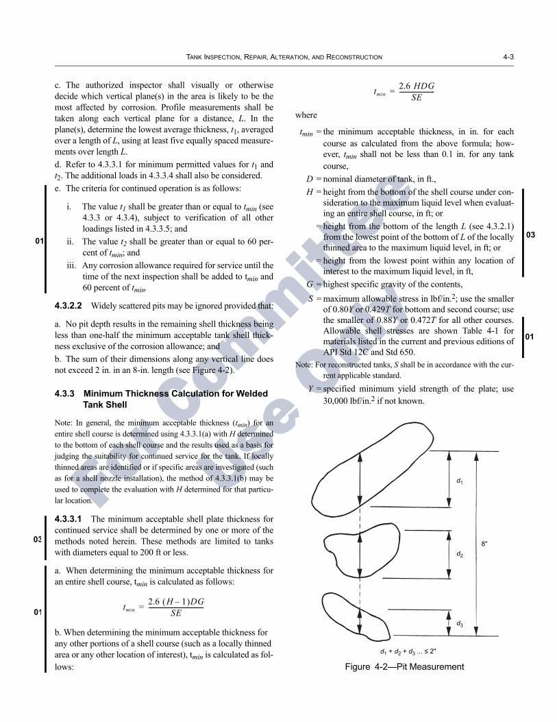
4.3.2.2 Widely scattered pits may be ignored provided that:
a. No pit depth results in the remaining shell thickness being less than one-half the minimum acceptable tank shell thick-ness exclusive of the corrosion allowance; andb. The sum of their dimensions along any vertical line does not exceed 2 in. in an 8-in. length (see Figure 4-2).
4.3.3 Minimum Thickness Calculation for Welded Tank Shell
Note: In general, the minimum acceptable thickness (tmin) for an entire shell course is determined using 4.3.3.1(a) with H determined to the bottom of each shell course and the results used as a basis for judging the suitability for continued service for the tank. If locally thinned areas are identified or if specific areas are investigated (such as for a shell nozzle installation), the method of 4.3.3.1(b) may be used to complete the evaluation with H determined for that particu-lar location.
4.3.3.1 The minimum acceptable shell plate thickness for continued service shall be determined by one or more of the methods noted herein. These methods are limited to tanks with diameters equal to 200 ft or less.
a. When determining the minimum acceptable thickness for an entire shell course, tmin is calculated as follows:
tmin2.6 H 1–( )DG
SE------------------------------------=
b. When determining the minimum acceptable thickness for any other portions of a shell course (such as a locally thinned area or any other location of interest), tmin is calculated as fol-lows:
tmin2.6 HDG
SE-----------------------=
where
tmin = the minimum acceptable thickness, in in. for each course as calculated from the above formula; how-ever, tmin shall not be less than 0.1 in. for any tank course,
D = nominal diameter of tank, in ft.,H = height from the bottom of the shell course under con-
sideration to the maximum liquid level when evaluat-ing an entire shell course, in ft; or
= height from the bottom of the length L (see 4.3.2.1) from the lowest point of the bottom of L of the locally thinned area to the maximum liquid level, in ft; or
= height from the lowest point within any location of interest to the maximum liquid level, in ft,
G = highest specific gravity of the contents,S = maximum allowable stress in lbf/in.2; use the smaller
of 0.80Y or 0.429T for bottom and second course; use the smaller of 0.88Y or 0.472T for all other courses. Allowable shell stresses are shown Table 4-1 for materials listed in the current and previous editions of API Std 12C and Std 650.
Note: For reconstructed tanks, S shall be in accordance with the cur-rent applicable standard.
Y = specified minimum yield strength of the plate; use 30,000 lbf/in.2 if not known.
Figure 4-2—Pit Measurement
d1
d2
d3
8"
d1 + d2 + d3

05
01
4-4 API STANDARD 653
01
01
08
05
For C
ommittee
Use O
nly
Material Specification and Grade
MinimumSpecified
Yield Stress, Y (lbf/in.2)
MinimumSpecifiedTensile
Strength, T (lbf/in.2)
Lower Two Courses Upper Courses Lower Two
Courses Upper Courses
A 283-C 30,000 55,000 23,600 26,000 26,000 27,000A285-C 30,000 55,000 23,600 26,000 26,000 27,000
A36 36,000 58,000 24,900 27,400 27,400 30,100A131-A, B, CS 34,000 58,000 24,900 27,400 27,400 30,100
A131-EH 36 51,000 71,000 30,500 33,500 33,500 36,800
A573-58 32,000 58,000 24,900 27,400 27,400 28,800A573-65 35,000 65,000 27,900 30,700 30,700 31,500A573-70 42,000 70,000 30,000 33,000 33,000 36,300
A516-55 30,000 55,000 23,600 26,000 26,000 27,000A516-60 32,000 60,000 25,600 28,200 28,200 28,800A516-65 35,000 65,000 27,900 30,700 30,700 31,500A516-70 38,000 70,000 30,000 33,000 33,000 34,200
A662-B 40,000 65,000 27,900 30,700 30,700 33,700A662-C 43,000 70,000 30,000 33,000 33,000 36,300
A537- Class 1 50,000 70,000 30,000 33,000 33,000 36,300A537- Class 2 60,000 80,000 34,300 37,800 37,800 41,500
A633-C, D 50,000 70,000 30,000 33,000 33,000 36,300A678-A 50,000 70,000 30,000 33,000 33,000 36,300A678-B 60,000 80,000 34,300 37,800 37,800 41,500A737-B 50,000 70,000 30,000 33,000 33,000 36,300
A841 50,000 70,000 30,000 33,000 33,000 36,300A10 (1) 30,000 55,000 23,600 26,000 26,000 27,000A7 (1) 33,000 60,000 25,700 28,300 28,300 29,700
A442-55 (1) 30,000 55,000 23,600 26,000 26,000 27,000A442-60 (1) 32,000 60,000 25,600 28,200 28,200 28,800
G40.21, 38W 38,000 60,000 25,700 28,300 28,300 31,100G40.21, 44W 44,000 65,000 27,900 30,700 30,700 33,700G40.21, 50W 50,000 65,000 27,900 30,700 30,700 33,700
G40.21, 50WT 50,000 70,000 30,000 33,000 33,000 36,300
Unknown (2) 30,000 55,000 23,600 26,000 26,000 27,000
Riveted Tanks:A7, A9 or A10 (1,3) NA NA 21,000 21,000 21,000 21,000
Known (4) Y T Note 4 Note 4 Note 4 Note 4Unknown (5) NA NA 21,000 21,000 21,000 21,000
ASTM Specifications
CSA Specifications
Stress, S (lbf/in.2) (7) Test Stress, St (lbf/in.2) (7)
(Not For Use For Reconstructed Tanks, see Note 6)
Allowable Product Allowable Hydrostatic
Table 4-1 Maximum Allowable Shell Stresses
Notes:
1. ASTM A7, A9, A10 and A442 are obsolete ASTM material spec-ifications previously listed in API Standards 12C and 650.
2. The yield stress and tensile strength values shown are per API 653 for welded AST material of unknown origin.
3. This provision is for riveted tanks, constructed of any grade of material, evaluated per 4.3.4.1 of this standard.
4. This provision is for riveted tanks, constructed of known grades of material, evaluated per 4.3.4.2 of this standard. For all courses, the
maximum allowable shell stress for both product and hydrostatic test conditions are listed under column for Allowable Product Stress, S.
5. This provision is for riveted tanks, constructed of unknown grades of material, evaluated per 4.3.4.2 of this standard.
6. The allowable stresses for reconstructed tanks are tabulated in API Std 650, Table 5-2 or calculated per 8.4 of this standard.
7. The allowable stresses are calculated per 4.3.3.1 and 4.3.3.2 of this standard, unless otherwise noted. The calculated allowable stresses are rounded to the nearest 100 lbf/in.2.

TANK INSPECTION, REPAIR, ALTERATION, AND RECONSTRUCTION 4-5
03
03
03
08
For C
ommittee
Use O
nly
T = the smaller of the specified minimum tensile strength of the plate or 80,000 lbf/in.2; use 55,000 lbf/in.2 if not known,
E = original joint efficiency for the tank. Use Table 4-2 if original E is unknown. E = 1.0 when evaluating the retirement thickness in a corroded plate, when away from welds or joints by at least the greater of 1 in. or twice the plate thickness.
4.3.3.2 If the tank will be hydrostatically tested, the hydro-static test height, Ht, shall be limited by one or more of the following methods. The tank shall not be filled above the level determined by the lesser value of Ht determined below:
a. After determining the controlling thickness of an entire shell course, Ht calculated as follows:
HtStEtmin
2.6D---------------- 1+=
b. After determining the controlling thickness by 4.3.2.1 for a locally thinned area, or at any other location of interest within a shell course, Ht is calculated as follows:
HtStEtmin
2.6D----------------=
where
Ht = Height from the bottom of the shell course under consideration to the hydrostatic test height when evaluating an entire shell course in ft; or
= Height from the bottom of the length, L, (see 4.3.2.1) for the most severely thinned area in each shell course to the hydrostatic test height in ft; or
= Height from the lowest point within any other location of interest to the hydrostatic test height in ft.
St = maximum allowable hydrostatic test stress in lbf/in.2; use the smaller of 0.88Y or 0.472T for bottom and second courses; use the smaller of 0.9Y or 0.519T for all other courses.
Notes: 1. Depending on the specific gravity of the content used to deter-mine tmin, Ht may be less than H. Testing the tank to H may yield the corroded area.2. If Ht is less than H, owner/operator shall determine the conse-quence and acceptability of operating the tank to H, its maximum design liquid level. Repairs to shell sections above Ht shall comply with the requirements of 12.3.2.3. For reconstructed tanks, St shall be per the current applicable stan-dard.
Table 4-2—Joint Efficiencies for Welded Joints
Edition& Year
Typeof Joint
JointEfficiency
EApplicability
or LimitsStandardAPI 650 7th & Later Butt 1.00 Basic Standard
(1980 – Present) Butt 0.85 Appendix A–Spot RT
Butt 0.70 Appendix A–No RT
1st – 6th Butt 0.85 Basic Standard
(1961 – 1978) Butt 1.00 Appendices D&G
API 12C 14th & 15th Butt 0.85
(1957 – 1958)
3rd – 13th Lapa 0.75 3/8 in. max. t
(1940 – 1956) Buttc 0.85
1st & 2nd Lapa 0.70 7/16 in. max. t
(1936 – 1939) Lapb 0.50 + k/5 1/4 in. max. t
Buttc 0.85
Unknown Lapa 0.70 7/16 in. max. t
Lapb 0.50 + k/5 1/4 in. max. t
Butt 0.70
Lapd 0.35
Notes: aFull double lap-welded.bFull fillet weld with at least 25 percent intermittent full fillet oppo-site side; k = percent of intermittent weld expressed in decimal form.cSingle butt-welded joints with a back-up bar were permitted from the years of 1936 to 1940 and 1948 to 1954.dSingle lap-welded only.
[Text removed.]
4.3.3.3 Alternatively, the minimum acceptable shell plate thickness for tanks with diameters equal to or less than 200 ft may be calculated in accordance with the variable design point method in API Std 650, 5.6.4, substituting “S x E” for “S”; E and S may be defined as in 4.3.3.1.
4.3.3.4 The variable design point method shall be used for tanks greater than 200 ft in diameter, with all variables defined as in 4.3.3.1.

4-6 API STANDARD 653
05
05
For C
ommittee
Use O
nly
4.3.3.5 The thickness determinations of 4.3.3.1, 4.3.3.2, and 4.3.3.3 consider liquid loading only. All other loads shall also be evaluated according to the original standard of con-struction; and engineering judgment shall be used to evaluate different conditions or new information. As applicable, the following loadings shall be taken into account:
a. Wind-induced buckling.
b. Seismic loads.
c. Operation at temperatures over 200°F.
d. Vacuum-induced external pressure.
e. External loads caused by piping, tank-mounted equip-ment, hold down lugs, etc.
f. Wind-induced overturning.
g. Loads due to settlement.
4.3.3.6 As an alternative to the procedures described above, any thinning of the tank shell below minimum required wall thickness due to corrosion or other wastage may be evaluated to determine the adequacy for continued service by employing the design by analysis methods defined in Section VIII, Division 2, Appendix 4 of the ASME Code; or API RP 579, Section 4, 5 or 6 as applicable. When using the ASME criteria, the stress value used in the original tank design shall be substituted for the Sm value of Division 2, if the design stress is less than or equal to the lesser of 2/3Y(specified minimum yield strength) or 1/3T (specified mini-mum tensile strength). If the original design stress is greater than 2/3Y or 1/3T, then the lesser of 1/3Y or 1/3T shall be substi-tuted for Sm
4.3.4 Minimum Thickness Calculation For Riveted Tank Shell
4.3.4.1 The minimum acceptable thickness for riveted tank shells shall be calculated using the formula of 4.3.3.1 except that the following allowable stress criteria and joint efficien-cies shall be used:
S = 21,000 lbf/in.2
E = 1.0 for shell plate 6 in. or more away from riv-ets. See Table 4-3 for joint efficiencies for loca-tions within 6 in. of rivets.
4.3.4.2 The rivet joint efficiencies given in Table 4-3 are conservative minimums for riveted tank construction details and are included to simplify riveted tank evaluations. How-ever, in some cases it may be advantageous to calculate the actual rivet joint efficiencies using computational methods
applicable to lap and butt type riveted joints. When this alter-native of calculated joint efficiencies is used, the following maximum allowable stresses shall apply:
a. For the maximum tensile stress in net section of plate, use the lesser of 0.80Y or 0.429T; use 21,000 lbf/in.2 if T or Y is unknown.
b. For the maximum shear in net section of rivet, use 16,000 lbf/in.2
c. For the maximum bearing stress on plates or rivets, use 32,000 lbf/in.2 for rivets in single shear, and 35,000 lbf/in.2for rivets in double shear.
4.3.4.3 For tanks with riveted joints, consideration shall be given to whether, and to what extent, corrosion affects such joints. If calculations show that excess thickness exists, this excess may be taken as corrosion allowance.
4.3.4.4 Non-liquid loads (see 4.3.3.5) shall also be consid-ered in the analysis of riveted tanks.
4.3.5 Distortions
4.3.5.1 Shell distortions include out-of-roundness, buckled areas, flat spots, and peaking and banding at welded joints.
4.3.5.2 Shell distortions can be caused by many conditions such as foundation settlement, over- or under-pressuring, high wind, poor shell fabrication, or repair techniques, and so forth.
4.3.5.3 Shell distortions shall be evaluated on an individual basis to determine if specific conditions are considered acceptable for continuing tank service and/or the extent of corrective action.
4.3.6 Flaws
Flaws such as cracks or laminations shall be thoroughly examined and evaluated to determine their nature and extent and need for repair. If a repair is needed, a repair procedure shall be developed and implemented. The requirement for repairing scars such as arc strikes, gouges, or tears from tem-porary attachment welds must be evaluated on a case-by-case basis. Cracks in the shell-to-bottom weld shall be removed.
4.3.7 Wind Girders and Shell Stiffeners
The evaluation of an existing tank shell for suitability for service must also consider the details and condition of any wind girders or shell stiffeners. Degradation by corrosion of these structural elements or their attachment welds to the shell may render these elements inadequate for the design conditions.
TANK INSPECTION, REPAIR, ALTERATION, AND RECONSTRUCTION 4-7
05
05
05
For C
ommittee
Use O
nly
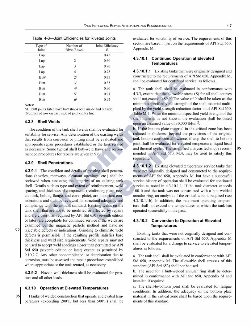
Table 4-3—Joint Efficiencies for Riveted Joints
Type of Joint
Number of Rivet Rows
Joint Efficiency E
Lap 1 0.45Lap 2 0.60Lap 3 0.70Lap 4 0.75Butta 2b 0.75Butt 3b 0.85Butt 4b 0.90Butt 5b 0.91Butt 6b 0.92
Notes: aAll butt joints listed have butt straps both inside and outside. bNumber of row on each side of joint center line.
4.3.8 Shell Welds
The condition of the tank shell welds shall be evaluated for suitability for service. Any deterioration of the existing welds that results from corrosion or pitting must be evaluated and appropriate repair procedures established or the tank rerated as necessary. Some typical shell butt-weld flaws and recom-mended procedures for repairs are given in 9.6.
4.3.9 Shell Penetrations
4.3.9.1 The condition and details of existing shell penetra-tions (nozzles, manways, cleanout openings, etc.) shall be reviewed when assessing the integrity of an existing tank shell. Details such as type and extent of reinforcement, weld spacing, and thickness of components (reinforcing plate, noz-zle neck, bolting flange, and cover plate), are important con-siderations and shall be reviewed for structural adequacy and compliance with the as-built standard. Existing welds on the tank shell that are not to be modified or affected by repairs and are closer than required by API Std 650 (seventh edition or later) are acceptable for continued service if the welds are examined by the magnetic particle method and have no rejectable defects or indications. Grinding to eliminate weld defects is permissible if the resulting profile satisfies base thickness and weld size requirements. Weld repairs may not be used to accept weld spacings closer than permitted by API Std 650 (seventh edition or later) except as permitted by 9.10.2.7. Any other noncompliance, or deterioration due to corrosion, must be assessed and repair procedures established where appropriate or the tank rerated, as necessary.
4.3.9.2 Nozzle wall thickness shall be evaluated for pres-sure and all other loads.
4.3.10 Operation at Elevated Temperatures
ITanks of welded construction that operate at elevated tem-peratures (exceeding 200ºF, but less than 500ºF) shall be
evaluated for suitability of service. The requirements of this section are based in part on the requirements of API Std. 650, Appendix M.
4.3.10.1 Continued Operation at Elevated Temperatures
4.3.10.1.1 Existing tanks that were originally designed and constructed to the requirements of API Std 650, Appendix M, shall be evaluated for continued service, as follows.
a. The tank shell shall be evaluated in conformance with 4.3.3, except that the allowable stress (S) for all shell courses shall not exceed 0.80 Y. The value of Y shall be taken as the minimum specified yield strength of the shell material multi-plied by the yield strength reduction factor in of API Std 650, Table M-1. When the minimum specified yield strength of the shell material is not known, the evaluation shall be based upon an assumed value of 30,000 lbf/in.2.b. If the bottom plate material in the critical zone has been reduced in thickness beyond the provisions of the original tank bottom corrosion allowance, if any, the shell-to-bottom joint shall be evaluated for elevated temperature, liquid head and thermal cycles. The simplified analysis technique recom-mended in API Std 650, M.4, may be used to satisfy this requirement.
4.3.10.1.2 Existing elevated temperature service tanks that were not originally designed and constructed to the require-ments of API Std 650, Appendix M, but have a successful service history of operation shall be evaluated for continued service as noted in 4.3.10.1.1. If the tank diameter exceeds 100 ft and the tank was not constructed with a butt-welded annular ring, an analysis of the critical zone is required (see 4.3.10.1.1b). In addition, the maximum operating tempera-ture shall not exceed the temperatures at which the tank has operated successfully in the past.
4.3.10.2 Conversion to Operation at Elevated Temperatures
Existing tanks that were not originally designed and con-structed to the requirements of API Std 650, Appendix M shall be evaluated for a change to service to elevated temper-atures as follows.
a. The tank shell shall be evaluated in conformance with API Std 650, Appendix M. The allowable shell stresses of this standard (API Std 653) shall not be used.b. The need for a butt-welded annular ring shall be deter-mined in conformance with API Std 650, Appendix M and installed if required.c. The shell-to-bottom joint shall be evaluated for fatigue conditions. In addition, the adequacy of the bottom plate material in the critical zone shall be based upon the require-ments of this standard.

4-8 API STANDARD 653
08
08
For C
ommittee
Use O
nly
4.4 TANK BOTTOM EVALUATION
4.4.1 General
Tank bottom inspection strategies shall provide suitable data which, when used with the procedures in this standard, will determine the tank bottom integrity necessary to pre-vent leakage of fluids that may cause environmental dam-age. Each aspect of corrosion phenomena, and other potential leak or failure mechanism must be examined. Peri-odic assessment of tank bottom integrity shall be performed in addition to the internal inspections specified in 6.4. The assessment period shall be less than or equal to the appro-priate internal inspection interval given in 6.4.2 or 6.4.3. The use of leak detection tests or monitoring systems (such as double bottoms or liners under tank bottoms with leak detection pipes) will satisfy the requirement for periodic assessment between internal inspections.
Excessive foundation settlement of storage tanks can affect the integrity of tank shells and bottoms. Therefore, monitor-ing the settlement behavior of tanks is a recognized practice to assess the integrity of tank bottoms. Refer to Appendix B for techniques for evaluating tank bottom settlement.
4.4.2 Causes of Bottom Failure
The following list gives some historical causes of tank bot-tom leakage or failure that shall be considered in the decision to line, repair, or replace a tank bottom:
a. Internal pitting and pitting rates in the anticipated service.b. Corrosion of weld joints (weld and heat affected zone).c. Weld joint cracking history.d. Stresses placed on the bottom plates by roof support loads and shell settlement.e. Underside corrosion (normally in the form of pitting).f. Inadequate drainage resulting in surface water flowing under the tank bottom.g. The lack of an annular plate ring when required.h. Uneven settlement that results in high localized stresses in the bottom plates.i. Roof support columns or other supports welded to the tank bottom where adequate allowance for movement was not made.j. Rock or gravel foundation pads with inadequately filled-in surface voids.k. Nonhomogeneous fill under the tank bottom (for example, a lump of clay in a sand foundation pad).l. Inadequately supported sumps.
4.4.3 Tank Bottom Release Prevention Systems
API supports the use of a Release Prevention System (RPS) to maintain the integrity of tank bottoms. The term RPS refers to the suite of API standards and recommended practices that are designed to maintain tank integrity and thus
protect the environment. With respect to tank bottoms, these include: internal inspection of the tank bottom; leak detection systems and leak testing of the tank; installing cathodic pro-tection for the underside of the tank bottom; lining the bottom of the tank interior; providing a Release Prevention Barrier (RPB) under the tank bottom; or some combination of these measures, depending on the operating environment and ser-vice of the tank.
4.4.3.1 Internal Inspection
Internal inspection of the tank bottom is intended to assess the current bottom integrity and identify problem conditions that may lead to future loss of integrity. Internal inspection techniques, such as bottom settlement monitoring, and con-siderations for determining appropriate inspection frequency, are found in 4.4.6., Section 6, Appendices B and C, and else-where.
4.4.3.2 Leak Detection Systems and Leak Testing
Tank leak detection systems and leak testing are intended to identify, quantify, and/or locate a tank bottom integrity fail-ure that is not detectable visually or through inventory recon-ciliation. Leak detection may be integral to the tank design, either as constructed or as modified (e.g., RPB with intersti-tial monitoring) or may operate separately (e.g., soil vapor monitoring and chemical marker); may be operated by the tank owner or as a third party test or service; and may detect leaks continuously or on a periodic basis. Tank leak detection systems and testing methods are listed and discussed in API RP 575.
4.4.3.3 Cathodic Protection
Cathodic protection systems are intended to mitigate corro-sion of steel surfaces in contact with soil, such as the under-side of tank bottoms. A selection basis for cathodic protection systems is covered by API RP 651.
4.4.3.4 Internal Lining Protection
Internal linings and coatings for the top side of the tank bottom are intended to mitigate corrosion by providing a bar-rier between the tank bottom and corrosion sources. Applied linings and coatings for internal surfaces of tank bottoms are covered by API RP 652.
4.4.3.5 Release Prevention Barriers
An RPB includes steel bottoms, synthetic materials, clay liners, concrete pads, and all other barriers or combinations of barriers placed in the bottom of or under a tank, which have the function of: 1) preventing the escape of released material, and 2) containing or channeling released material for leak

TANK INSPECTION, REPAIR, ALTERATION, AND RECONSTRUCTION 4-9
08
03
For C
ommittee
Use O
nly
detection. RPB design is covered in detail in Appendix I of API 650. Replacement of tank bottoms is covered in 9.10.2.
If a decision is made to replace an existing bottom, API supports the evaluation of installing an RPB or continued use of an RPS. The evaluation should consider the effectiveness of other RPS controls, the product stored, the location of the tank, and environmental sensitivities.
4.4.4 Bottom Plate Thickness MeasurementsVarious methods for determining tank bottom plate soilside
corrosion are available. The methods vary to the extent by which they can reliably measure general corrosion and pitting. A combination of these methods may be required along with extrapolation techniques and analysis to establish the probable conditions of the entire tank bottom. Magnetic flux leakage (MFL) tools are commonly used, along with ultrasonic (UT) thickness measurement tools, to examine tank bottoms. Ultra-sonic thickness measurement techniques are often used to confirm and further quantify data obtained by MFL examina-tion, but these techniques may not be required depending on the specific procedure and application. The quality of data obtained from both MFL and ultrasonic thickness techniques is dependent on personnel, equipment and procedures. Appendix G may be used to provide guidance in qualifying personnel and procedures for obtaining thickness data.
4.4.5 Minimum Thickness for Tank Bottom PlateQuantifying the minimum remaining thickness of tank bot-
toms based on the results of measurement can be done by the method outlined in 4.4.7.1. Other approaches such as the probabilistic method in 4.4.7.2 may be used.
4.4.5.1 An acceptable method for calculating the minimum acceptable bottom thickness for the entire bottom or portions thereof is as follows:
MRT = (Minimum of RTbc or RTip) – Or (StPr + UPr)
where
MRT = minimum remaining thickness at the end of interval Or. This value must meet the require-ments of Table 6-1 and 4.4.7.4 and 4.4.8,
Or = in-service interval of operation (years to next internal inspection) not to exceed that allowed by 6.4.2,
RTbc = minimum remaining thickness from bottom side corrosion after repairs,
RTip = minimum remaining thickness from internal corrosion after repairs,
StPr = maximum rate of corrosion not repaired on the top side. StPr = 0 for coated areas of the bottom.
The expected life of the coating must equal or exceed Or to use StPr = 0,
UPr = maximum rate of corrosion on the bottom side. To calculate the corrosion rate, use the minimum remaining thickness after repairs. Assume a linear rate based on the age of the tanks. UPr = 0 for areas that have effective cathodic protection.
Note: For areas of a bottom that have been scanned by the magnetic flux leakage (or exclusion) process, and do not have effective cathodic protection, the thickness used for calculating UPr must be the lesser of the MFL threshold or the minimum thickness of corrosion areas that are not repaired. The MFLthreshold is defined as the minimum remaining thickness to be detected in the areas inspected. This value should be predetermined by the tank owner based on the desired inspection interval. Areas of bottom side corrosion that are repaired should be evaluated with the corrosion rate for the repaired area unless the cause of corrosion has been removed. The evaluation is done by using the corro-sion rate of the repaired area for UPr, and adding the patch plate (if used) thickness to the term “minimum of RTbc or RTip.”
Note: Corrosion of the bottom plate includes loss of metal from iso-lated or general corrosion.
4.4.5.2 For the probabilistic method, a statistical analysis is made of thickness data from measurements (see 4.4.6) pro-jecting remaining thickness, based on sample scanning of the bottom.
4.4.5.3 If the minimum bottom thicknesses, at the end of the in-service period of operation, are calculated to be less than the minimum bottom renewal thicknesses given in Table 6-1, or less than the minimum bottom renewal thicknesses providing acceptable risk as determined by a risk-based inspection meth-odology, the bottom shall be lined, repaired, replaced, or the interval to the next internal inspection shortened.
4.4.5.4 Unless a stress analysis is performed, the minimum bottom plate thickness in the critical zone of the tank bottom defined in 9.10.1.2 shall be the smaller of 1/2 the original bot-tom plate thickness (not including the original corrosion allowance) or 50 percent of tmin of the lower shell course per 4.3.3.1 but not less than 0.1 in. Isolated pitting will not appre-ciably affect the strength of the plate.
4.4.5.5 The repair of internal pitting, when performed to extend the in-service period of operation, shall be by pit welding, overlay welding, or lap patching, followed by inspection and testing. The extent of weld repairs is limited in the critical zone in accordance with 9.10.1.2.

4-10 API STANDARD 653
08
08
For C
ommittee
Use O
nly
4.4.5.6 The treatment of bottom pitting by the use of non-welded repairs (for example, coatings, caulking) can not be used to increase RTip for calculating MRT.4.4.5.7 The thickness of the projection of the bottom plate beyond the shell as measured at the toe of the outside bottom-to-shell fillet weld shall not be less than 0.1 in. The projection of the bottom plate beyond the outside toe of the shell-to-bot-tom weld shell shall be at least 3/8 in.
4.4.6 Minimum Thickness for Annular Plate Ring4.4.6.1 Due to strength requirements, the minimum thickness of annular plate ring is usually greater than 0.10 in. Isolated pitting will not appreciably affect the strength of the plate. Unless a stress analysis is performed, the annu-lar plate thickness shall be in accordance with 4.4.8.2 or 4.4.8.3, as applicable.4.4.6.2 For tanks in service with a product specific gravity less than 1.0, which require annular plates for other than seis-mic loading considerations, the thickness of the annular plates shall be not less than the thicknesses given in Table 4-4, plus any specified corrosion allowance.4.4.6.3 For tanks in service with a product specific gravity of 1.0 or greater, which require annular plates for other than seismic loading considerations, the thickness of the annular plates shall be in accordance with API Std 650, Table 5-1, plus any specified corrosion allowance.4.4.6.4 For tanks that utilize thickened annular plates for seismic considerations, a seismic evaluation shall be performed in accordance with the requirements of the as built standard, using the actual thickness of the existing annular plate.4.4.6.5 For the thickness and projection of the annular plate beyond the shell refer to 4.4.7.7.
4.5 TANK FOUNDATION EVALUATION
4.5.1 General
Table 4-4—Annular Bottom Plate Thicknesses (in.)(Product Specific Gravity < 1.0)
Plate Thicknessa
of First ShellCourse (in.)
Stressb in First Shell Course(lbf/in.2)
< 24,300 < 27,000 < 29,700 < 32,400
t ≤ 0.75 0.17 0.20 0.23 0.30
0.75 < t ≤ 1.00 0.17 0.22 0.31 0.38
1.00 < t ≤ 1.25 0.17 0.26 0.38 0.48
1.25 < t ≤ 1.50 0.22 0.34 0.47 0.59
t > 1.50 0.27 0.40 0.53 0.68
Note: The thicknesses specified in the table are based on the founda-tion providing a uniform support under the full width of the annular plate. Unless the foundation is properly compacted, particularly at the inside of a concrete ringwall, settlement will produce additional stresses in the annular plate.aPlate thickness refers to the tank shell as constructed.bStresses are calculated from [2.34 D (H – 1)]/t.
4.5.1.1 The principal causes of foundation deterioration are settlement, erosion, cracking, and deterioration of con-crete initiated by: calcining, attack by underground water, attack by frost, and attack by alkalies and acids. To ensure suitability for service, all tank foundations shall be inspected periodically (see 6.3).
4.5.1.2 Some mechanisms of concrete deterioration are briefly described below:
a. Calcining (loss of water of hydration) can occur when con-crete has been exposed to sufficiently high temperature for a period of time. During intermediate cooling periods, the con-crete can absorb moisture, swell, lose its strength, and crack.
b. Deterioration of concrete exposed to underground water can be caused by chemical attack, by cyclic changes in tem-perature, and by freezing moisture.
c. Expansion of freezing moisture in porous concrete, or in concrete with minor settlement cracks or temperature cracks, can result in spalling and/or the development of serious struc-tural cracks.d. Sulfate-type alkalies, and to a lesser extent, chlorides, can act corrosively to destroy the bond of the concrete.e. Temperature cracks (hairline cracks of uniform width) do not seriously affect the strength of the concrete foundation structure; however, these cracks can be potential access points for moisture or water seepage that could eventually result in corrosion of the reinforcing steel.
4.5.1.3 When a tank is to be used in elevated temperature (> 90°C (200°F)) service, the provisions of API Std 650, Sec-tion B.6 shall be considered in the evaulatuion of the suitabil-ity for service of the tank foundation.
4.5.2 Foundation Repair or Replacement
4.5.2.1 If there is a need for foundation repair or replace-ment, foundations shall be restored to the tolerance limits of 10.5.6.
4.5.2.2 Concrete pads, ringwalls, and piers, showing evi-dence of spalling, structural cracks, or general deterioration, shall be repaired to prevent water from entering the concrete structure and corroding the reinforcing steel.
4.5.3 Anchor Bolts
Distortion of anchor bolts and excessive cracking of the concrete structures in which they are embedded may be indi-cations of either serious foundation settlement or a tank over-pressure uplift condition.

05
05
05
05
05
05
05
05
05
05
05
05
05
08
05
08
05
For C
ommittee
Use O
nly
SECTION 5—BRITTLE FRACTURE CONSIDERATIONS
5.1 GENERAL
This section provides a procedure for the assessment of existing tanks for suitability for continued operation or change of service with respect to the risk of brittle fracture and does not supplement or replace the requirements of Sec-tion 12 for the hydrostatic testing of repaired, modified, or reconstructed tanks. The procedure applies to both welded and riveted tanks; however, the procedure is based primarily on experience and data obtained from welded tanks.
5.2 BASIC CONSIDERATIONS
5.2.1 A decision tree, Figure 5-1, is used to present the assessment procedure for failure due to brittle fracture. The decision tree is based on the following principles:
5.2.2 In all reported incidents of tank failure due to brittle fracture, failure occurred either shortly after erection during hydrostatic testing or on the first filling in cold weather, after a change to lower temperature service, or after a repair/alter-ation. This experience shows that once a tank has demon-strated the ability to withstand the combined effects of maximum liquid level (highest stresses) and lowest operating temperature without failing, the risk of failure due to brittle fracture with continued service is minimal.
5.2.3 Any change in service must be evaluated to deter-mine if it increases the risk of failure due to brittle fracture. In the event of a change to a more severe service (such as oper-ating at a lower temperature or handling product at a higher specific gravity) it is necessary to consider the need for a hydrostatic test to demonstrate fitness for a new more severe service. The following aspects should be considered:
a. The likelihood of repairs/alterations since the original hydrostatic test not meeting requirements of this standard.b. Deterioration of the tank since original hydrostatic test.
5.3 ASSESSMENT PROCEDURE
5.3.1 The assessment procedure illustrated in Figure 5-1shall be used. Each of the key steps, numbered 1 through 11 on the decision tree, correspond sequentially to the explana-tions provided below.
5.3.2 Step 1—The tanks meet the requirements of API Std 650 (seventh edition or later) or API Std 650, Appendix G (fifth and sixth editions) to minimize the risk of failure due to brittle fracture. Alternatively, tanks may also be shown to meet the toughness requirements of API Std 650 (seventh edition or later) by impact testing coupon samples from a rep-resentative number of shell plates.
5.3.3 Step 2—Many tanks that continue to operate suc-cessfully in the same service were not built to the require-ments of API Std 650 (see editions and appendices named in 5.3.2). These tanks are potentially susceptible to failure due to brittle fracture and require an assessment as illustrated by the decision tree.
5.3.4 Step 3—For the purpose of this assessment, hydro-static testing demonstrates fitness for continued service with minimal risk of failure due to brittle fracture, provided that all governing requirements for repairs, alterations, reconstruction, or change in service are in accordance with this standard (including a need for hydrostatic testing after major repairs, major alterations or reconstruction). The effectiveness of the hydrostatic test in demonstrating fit-ness for continued service is shown by industry experience.
5.3.5 Step 4—If a tank shell thickness is no greater than 0.5 in., the risk of failure due to brittle fracture is minimal, provided that an evaluation for suitability of service in accordance with Section 4 has been performed. The original nominal thickness for the thickest tank shell plate shall be used for this assessment.
5.3.6 Step 5—No known tank failures due to brittle fracture have occurred at shell metal temperatures of 60°F or above. Similar assurance against brittle fracture can be gained by increasing the metal temperature by heating the tank contents.
5.3.7 Step 6—Industry experience and laboratory tests have shown that a membrane stress in tank shell plates of at least 7 ksi is required to cause failure due to brittle fracture.
5.3.8 Step 7—Tanks constructed from steels listed in Fig-ure 4-1 of API Std 650 can be used in accordance with their exemption curves, provided that an evaluation for suitability of service in conformance with Section 4 of this standard has been performed. Additionally, tanks constructed in accor-dance with another nationally recognized code or standard containing toughness rules (such as API Std 620) may be used in accordance with the current toughness rules of that stan-dard. Tanks fabricated from steels of unknown material speci-fications, thicker than 1/2 in. and operating at a shell metal temperature below 60°F, can be used if the tank meets the requirements of Figure 5-2. The original nominal thickness for thickest tank shell plate shall be used for the assessment. For unheated tanks, the shell metal temperature shall be the design metal temperature as defined in API Std 650, 4.2.9.1.
5.3.9 Step 8—The risk of failure due to brittle fracture is minimal once a tank has demonstrated that it can operate at a specified maximum liquid level at the lowest expected tem-perature without failing. For the purpose of this assessment,
5-1

5-2 API STANDARD 653
08
For C
ommittee
Use O
nly
Tank
mee
ts A
PI 6
50
(7th
edi
tion
or la
ter)
or A
PI 6
50,
Appe
ndix
G
(5th
or 6
th e
ditio
n).
Tank
cont
inue
sto
ope
rate
in s
ame
serv
ice
?
Alte
ratio
ns,
repa
irs a
ndre
cons
truct
ion
Mee
tsAP
I 653
?
Tank
doe
s no
tm
eet A
PI 6
50(1
980)
or A
PI 6
50,
Appe
ndix
G
(5th
or 6
th e
ditio
n).
Prio
rhy
dro
dem
onst
rate
sfit
ness
for
cont
inue
dse
rvic
e?
Tank
thic
knes
s 0
.5 in
ch?
Cha
nge
in s
ervi
ce
1 2 11
34
56
78
93
10
Is s
ervi
cem
ore
seve
re?
Ope
rate
sat
met
alte
mpe
ratu
reab
ove
60F ?
Mem
bran
est
ress
belo
w7
ksi
?
Tank full
at lo
wes
ton
e da
yte
mpe
ratu
re p
erAP
I 650
Fig.
4-2
?
Doe
s ta
nkm
eet t
here
quire
men
tsof
API
650
or e
qual
?
Tank
cont
inue
sto
ope
rate
in s
ame
serv
ice
?
Hyd
rote
st to
dem
onst
rate
fitne
ss fo
rco
ntin
ued
serv
ice
Yes
Yes
Yes
Yes
Yes
Yes
Yes
Yes
Yes
Yes
Yes
Use
Use
Use
Use
Use
Use
Use
Use
No
No N
o
(See
not
e)
No
Con
tinue
to u
se
Con
tinue
to u
se
Con
tinue
to u
se
No
No
No
No
No
Rer
ate
tank
bas
edon
prio
r ope
ratin
ghi
stor
y
met
al te
mpe
ratu
re
Not
e: T
his
does
not
exem
pt ta
nks
from
oth
erhy
drot
est r
equi
rem
ents
stip
ulat
ed in
this
sta
ndar
d.
Tank
st
eel e
xem
pt fr
om im
pact
test
ing
AP
I 650
Fig
4-1
or
AP
I 653
Fi
g. 5
-2?
Figu
re 5
-1—
Britt
le F
ract
ure
Con
side
ratio
ns
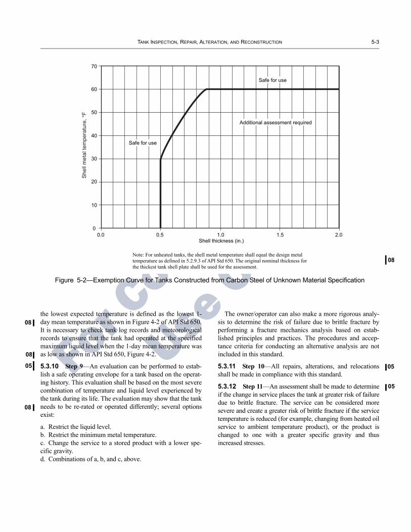
08
TANK INSPECTION, REPAIR, ALTERATION, AND RECONSTRUCTION 5-3
08
08
05
08
05
05
For C
ommittee
Use O
nlyFigure 5-2—Exemption Curve for Tanks Constructed from Carbon Steel of Unknown Material Specification
60
70
50
40
30
20
10
00.50.0 1.0 1.5 2.0
Shell thickness (in.)
Note: For unheated tanks, the shell metal temperature shall equal the design metal temperature as defined in 5.2.9.3 of API Std 650. The original nominal thickness for the thickest tank shell plate shall be used for the assessment.
Safe for use
Safe for use
Additional assessment required
the lowest expected temperature is defined as the lowest 1-day mean temperature as shown in Figure 4-2 of API Std 650. It is necessary to check tank log records and meteorological records to ensure that the tank had operated at the specified maximum liquid level when the 1-day mean temperature was as low as shown in API Std 650, Figure 4-2.
5.3.10 Step 9—An evaluation can be performed to estab-lish a safe operating envelope for a tank based on the operat-ing history. This evaluation shall be based on the most severe combination of temperature and liquid level experienced by the tank during its life. The evaluation may show that the tank needs to be re-rated or operated differently; several options exist:
a. Restrict the liquid level.b. Restrict the minimum metal temperature.c. Change the service to a stored product with a lower spe-cific gravity.d. Combinations of a, b, and c, above.
The owner/operator can also make a more rigorous analy-sis to determine the risk of failure due to brittle fracture by performing a fracture mechanics analysis based on estab-lished principles and practices. The procedures and accep-tance criteria for conducting an alternative analysis are not included in this standard.
5.3.11 Step 10—All repairs, alterations, and relocations shall be made in compliance with this standard.
5.3.12 Step 11—An assessment shall be made to determine if the change in service places the tank at greater risk of failure due to brittle fracture. The service can be considered more severe and create a greater risk of brittle fracture if the service temperature is reduced (for example, changing from heated oil service to ambient temperature product), or the product is changed to one with a greater specific gravity and thus increased stresses.

For C
ommittee
Use O
nly

08
For C
ommittee
Use O
nly
SECTION 6—INSPECTION
6.1 GENERAL
Periodic in-service inspection of tanks shall be performedas defined herein. The purpose of this inspection is to assurecontinued tank integrity. Inspections, other than those definedin 6.3 shall be directed by an authorized inspector.
6.2 INSPECTION FREQUENCY CONSIDERATIONS
6.2.1 Several factors must be considered to determineinspection intervals for storage tanks. These include, but arenot limited to, the following:
a. The nature of the product stored.b. The results of visual maintenance checks.c. Corrosion allowances and corrosion rates.d. Corrosion prevention systems.e. Conditions at previous inspections.f. The methods and materials of construction and repair.g. The location of tanks, such as those in isolated or high riskareas.h. The potential risk of air or water pollution.i. Leak detection systems.j. Change in operating mode (for example: frequency of fillcycling, frequent grounding of floating roof support legs).k. Jurisdictional requirements.l. Changes in service (including changes in water bottoms).m. The existence of a double bottom or a release preventionbarrier.
6.2.2 The interval between inspections of a tank (bothinternal and external) should be determined by its service his-tory unless special reasons indicate that an earlier inspectionmust be made. A history of the service of a given tank or atank in similar service (preferably at the same site) should beavailable so that complete inspections can be scheduled witha frequency commensurate with the corrosion rate of the tank.On-stream, nondestructive methods of inspection shall beconsidered when establishing inspection frequencies.
6.2.3 Jurisdictional regulations, in some cases, control thefrequency and interval of the inspections. These regulationsmay include vapor loss requirements, seal condition, leakage,proper diking, and repair procedures. Knowledge of such reg-ulations is necessary to ensure compliance with schedulingand inspection requirements.
6.3 INSPECTIONS FROM THE OUTSIDE OF THE TANK
6.3.1 Routine In-Service Inspections
6.3.1.1 The external condition of the tank shall be moni-tored by close visual inspection from the ground on a routine
basis. This inspection may be done by owner/operator per-sonnel, and can be done by other than authorized inspectorsas defined in 3.6. Personnel performing this inspection shouldbe knowledgeable of the storage facility operations, the tank,and the characteristics of the product stored.
6.3.1.2 The interval of such inspections shall be consistentwith conditions at the particular site, but shall not exceed onemonth.
6.3.1.3 This routine in-service inspection shall include avisual inspection of the tank’s exterior surfaces. Evidence ofleaks; shell distortions; signs of settlement; corrosion; andcondition of the foundation, paint coatings, insulation sys-tems, and appurtenances should be documented for follow-upaction by an authorized inspector.
6.3.2 External Inspection
6.3.2.1 All tanks shall be given a visual external inspectionby an authorized inspector. This inspection shall be called theexternal inspection and must be conducted at least every 5years or RCA/4N years (where RCA is the difference betweenthe measured shell thickness and the minimum requiredthickness in mils, and N is the shell corrosion rate in mils peryear) whichever is less. Tanks may be in operation during thisinspection.
6.3.2.2 Insulated tanks need to have insulation removedonly to the extent necessary to determine the condition of theexterior wall of the tank or the roof.
6.3.2.3 Tank grounding system components such as shuntsor mechanical connections of cables shall be visuallychecked. Recommended practices dealing with the preven-tion of hydrocarbon ignition are covered by API RP 2003.
6.3.3 Ultrasonic Thickness Inspection
6.3.3.1 External, ultrasonic thickness measurements of theshell can be a means of determining a rate of uniform generalcorrosion while the tank is in service, and can provide anindication of the integrity of the shell. The extent of suchmeasurements shall be determined by the owner/operator.
6.3.3.2 When used, the ultrasonic thickness measurementsshall be made at intervals not to exceed the following:
a. When the corrosion rate is not known, the maximum inter-val shall be 5 years. Corrosion rates may be estimated fromtanks in similar service based on thickness measurementstaken at an interval not exceeding 5 years.b. When the corrosion rate is known, the maximum intervalshall be the smaller of RCA/2N years (where RCA is the dif-ference between the measured shell thickness and the
6-1
6-2 API STANDARD 653
03
05
For C
ommittee
Use O
nly
minimum required thickness in mils, and N is the shell corro-sion rate in mils per year) or 15 years.
6.3.3.3 Internal inspection of the tank shell, when the tankis out of service, can be substituted for a program of externalultrasonic thickness measurement if the internal inspectioninterval is equal to or less than the interval required in6.3.3.2b.
6.3.4 Cathodic Protection Surveys
6.3.4.1 Where exterior tank bottom corrosion is controlledby a cathodic protection system, periodic surveys of the sys-tem shall be conducted in accordance with API RP 651. Theowner/operator shall review the survey results.
6.3.4.2 The owner/operator shall assure competency ofpersonnel performing surveys.
6.4 INTERNAL INSPECTION
6.4.1 General
6.4.1.1 Internal inspection is primarily required to:
a. Ensure that the bottom is not severely corroded andleaking.b. Gather the data necessary for the minimum bottom andshell thickness assessments detailed in Section 6. As applica-ble, these data shall also take into account external ultrasonicthickness measurements made during in-service inspections(see 6.3.3).c. Identify and evaluate any tank bottom settlement.
6.4.1.2 All tanks shall have a formal internal inspectionconducted at the intervals defined by 6.4.2 or 6.4.3. Theauthorized inspector who is responsible for evaluation of atank must conduct a visual inspection and assure the qualityand completeness of the NDE results. If the internal inspec-tion is required solely for the purpose of determining the con-dition and integrity of the tank bottom, the internal inspectionmay be accomplished with the tank in-service utilizing vari-ous ultrasonic robotic thickness measurement and other on-stream inspection methods capable of assessing the thicknessof the tank bottom, in combination with methods capable ofassessing tank bottom integrity as described in 4.4.1. Electro-magnetic methods may be used to supplement the on-streamultrasonic inspection. If an in-service inspection is selected,the data and information collected shall be sufficient to evalu-ate the thickness, corrosion rate, and integrity of the tank bot-tom and establish the internal inspection interval, based ontank bottom thickness, corrosion rate, and integrity, utilizingthe methods included in this standard. An individual, knowl-edgeable and experienced in relevant inspection methodolo-gies, and the authorized inspector who is responsible forevaluation of a tank must assure the quality and completenessof the in-service NDE results.
6.4.2 Inspection Intervals
6.4.2.1 Intervals between internal inspections shall bedetermined by the corrosion rates measured during previousinspections or anticipated based on experience with tanks insimilar service. Normally, bottom corrosion rates will controland the inspection interval will be governed by the measuredor anticipated corrosion rates and the calculations for mini-mum required thickness of tank bottoms (see 4.4.7). Theactual inspection interval shall be set to ensure that the bot-tom plate minimum thicknesses at the next inspection are notless than the values listed in Table 6-1. In no case, however,shall the internal inspection interval exceed 20 years.
6.4.2.2 When corrosion rates are not known and similarservice experience is not available to estimate the bottomplate minimum thickness at the next inspection, the internalinspection interval shall not exceed 10 years.
6.4.3 Alternative Internal Inspection Interval
As an alternative to the procedures in 6.4.2, an owner-oper-ator may establish the internal inspection interval using risk-based inspection (RBI) procedures. Combining the assess-ment of the likelihood of tank leakage or failure and the con-sequence of tank leakage or failure is the essential element ofRBI. A RBI assessment may increase or decrease the internalinspection intervals obtained using the procedures of 6.4.2.1.The RBI process may be used to establish as acceptable therisk of a minimum bottom plate thickness at the next inspec-tion interval independent of the values in Table 6-1. The RBIassessment may also increase or decrease the 20-year inspec-tion interval described in 6.4.2.1. The initial RBI assessmentshall be reviewed and approved by an authorized inspectorand an engineer(s), knowledgeable and experienced in tankdesign (including tank foundations) and corrosion. The RBIassessment shall be subsequently reviewed and approved byan authorized inspector and an engineer(s), knowledgeableand experienced in tank design (including tank foundations)and corrosion, at intervals not to exceed 10 years, or moreoften if warranted by changes in service.
Some of the factors that should be considered in a RBIassessment of a tank include the following:
a. The material of construction, including liners and coat-ings, relative to the product temperature and ambientconditions.b. The as-built standard.c. The methods used for determination of the shell and bot-tom plate thickness.d. The availability and effectiveness of the inspection meth-ods and quality of the data collected.e. The analysis methods used to determine the product side,soil side, and external corrosion rates and the accuracy ofthese methods and corrosion rates.

TANK INSPECTION, REPAIR, ALTERATION, AND RECONSTRUCTION 6-3
05
For C
ommittee
Use O
nlyf. The availability, accuracy, and need for leak detectionmethods and procedures.g. The effectiveness of corrosion mitigation methods, such ascathodic protection systems, liners, and coatings.h. The quality of the maintenance, including previousrepairs.i. The probability of and type of failure, i.e., slow leak to theenvironment, tank bottom rupture or tank shell brittlefracture.j. The environmental consequence and likelihood of a tankleak or failure.k. The presence or absence of a release prevention barrier(RPB) under the primary tank bottom (see 4.4.5, Note 5).
Historic tank leakage and failure data and information willalso be important for this assessment.
It is essential that all RBI assessments be conducted bytrained, qualified individuals knowledgeable in RBI method-ology, and knowledgeable and experienced in tank founda-tion design, construction, and corrosion. RBI assessmentsshall be thoroughly documented, clearly defining all the fac-tors contributing to both the likelihood and consequence oftank leakage or failure.
After an effective RBI assessment is conducted, the resultscan be used to establish a tank inspection strategy and betterdefine the most appropriate inspection methods, appropriatefrequency for internal, external and on-stream inspections,and prevention and mitigation steps to reduce the likelihoodand consequence of a tank leak or failure.
6.5 ALTERNATIVE TO INTERNAL INSPECTION TO DETERMINE BOTTOM THICKNESS
In cases where construction, size, or other aspects allowexternal access to the tank bottom to determine bottom thick-ness, an external inspection in lieu of an internal inspection is
allowed to meet the data requirements of Table 6-1. However,in these cases, consideration of other maintenance items maydictate internal inspection intervals. This alternative approachshall be documented and made part of the permanent recordof the tank.
6.6 PREPARATORY WORK FOR INTERNAL INSPECTION
Specific work procedures shall be prepared and followedwhen conducting inspections that will assure personnelsafety and health and prevent property damage in the work-place (see 1.4).
6.7 INSPECTION CHECKLISTS
Appendix C provides sample checklists of items for con-sideration when conducting in-service and out-of-serviceinspections.
6.8 RECORDS
6.8.1 General
Inspection records form the basis of a scheduled inspec-tion/maintenance program. (It is recognized that records maynot exist for older tanks, and judgments must be based onexperience with tanks in similar services.) The owner/opera-tor shall maintain a complete record file consisting of threetypes of records, namely: construction records, inspectionhistory, and repair/alteration history.
6.8.2 Construction Records
Construction records may include nameplate information,drawings, specifications, construction completion report, andany results of material tests and analyses.
6.8.3 Inspection History
The inspection history includes all measurements taken,the condition of all parts inspected, and a record of allexaminations and tests. A complete description of anyunusual conditions with recommendations for correction ofdetails which caused the conditions shall also be included.This file will also contain corrosion rate and inspectioninterval calculations.
6.8.4 Repair/Alteration History
The repair/alteration history includes all data accumulatedon a tank from the time of its construction with regard torepairs, alterations, replacements, and service changes(recorded with service conditions such as stored product tem-perature and pressure). These records should include theresults of any experiences with coatings and linings.
Table 6-1—Bottom Plate Minimum Thickness
Minimum Bottom Plate Thicknessa at
Next Inspection(in.)
Tank Bottom/Foundation Design
0.10 Tank bottom/foundation design with no means for detection and containment of a bottom leak.
0.05 Tank bottom/foundation design with means to provide detection and containment of a bottom leak.
0.05 Applied tank bottom reinforced lining, > 0.05 in. thick, in accordance with API RP 652.
Note: aSee 4.4.7

6-4 API STANDARD 653
08
08
For C
ommittee
Use O
nly
6.9 REPORTS
6.9.1 General
For each external inspection performed per 6.3.2 and eachinternal inspection performed per 6.4, the AuthorizedInspector shall prepare a written report. These inspectionreports along with inspector recommendations and docu-mentation of disposition shall be maintained by the owner/operator for the life of the tank. Local jurisdictions mayhave additional reporting and record keeping requirementsfor tank inspections.
6.9.2 Report Contents
Reports shall include at a minimum the following informa-tion:
a. Date(s) of inspection;b. Type of inspection (external or internal);c. Scope of inspection, including any areas that were notinspected, with reasons given (e.g., limited scope of inspec-tion, limited physical access;d. Description of the tank (number, size, capacity, year con-structed, materials of construction, service history, roof andbottom design, etc.), if available;e. List of components inspected and conditions found (a gen-eral checklist such as found in Appendix C may be used toidentify the scope of the inspection) and deficiencies found;f. Inspection methods and tests used (visual, MFL, UT, etc.)and results of each inspection method or test;g. Corrosion rates of the bottom and shell;h. Settlement survey measurements and analysis (ifperformed);i. Recommendations per 6.9.3.1;j. Name, company, API Std 653 certification number andsignature of the Authorized Inspector responsible for theinspection;
Drawings, photographs, NDE reports and other pertinentinformation shall be appended to the report.
6.9.3 Recommendations
6.9.3.1 Reports shall include recommendations for repairsand monitoring necessary to restore the integrity of the tankper this Standard and/or maintain integrity until the nextinspection, together with reasons for the recommendations.The recommended maximum inspection interval and basisfor calculation that interval shall also be stated. Additionally,reports may include other less critical observations, sugges-tions and recommendations.
6.9.3.2 It is the responsibility of the owner/operator toreview the inspection findings and recommendations, estab-lish a repair scope, if needed, and determine the appropriatetiming for repairs, monitoring, and/or maintenance activi-ties. Typical timing considerations and examples of repairsare:
a. Prior to returning the tank to service—repairs critical tothe integrity of the tank (e.g., bottom or shell repairs).
b. After the tank is returned to service—minor repairs andmaintenance activity (e.g., drainage improvement, painting,gauge repairs, grouting, etc.).
c. At the next scheduled internal inspection—predicted oranticipated repairs and maintenance (e.g., coating renewal,planned bottom repairs, etc.).
d. Monitor condition for continued deterioration—(e.g., roofand/or shell plate corrosion, settlement, etc.).
The owner/operator shall ensure that the disposition of allrecommended repairs and monitoring is documented in writ-ing and that reasons are given if recommended actions aredelayed or deemed unnecessary.
6.10 NON-DESTRUCTIVE EXAMINATIONS
Personnel performing nondestructive examinations shallmeet the qualifications identified in 12.1.1.2, but need not becertified in accordance with Appendix D. The results of anyNDE work, however, must be considered in the evaluation ofthe tank by an authorized inspector.

05
01
05
05
For C
ommittee
Use O
nly
SECTION 7—MATERIALS
7.1 GENERAL
This section provides general requirements for the selec-tion of materials for the repair, alteration, and reconstructionof existing tanks. Specific requirements for repairs and alter-ations are covered in Section 9.
7.2 NEW MATERIALS
All new materials used for repair, alterations, or recon-struction shall conform to the current applicable standard.
7.3 ORIGINAL MATERIALS FOR RECONSTRUCTED TANKS
7.3.1 Shell and Bottom Plates Welded To The Shell
7.3.1.1 All shell plate materials and bottom plates weldedto the shell shall be identified. Materials identified by originalcontract drawings, API name plates, or other suitable docu-mentation do not require further identification. Material notidentified shall be tested and identified by the requirements asoutlined in 7.3.1.2. After identification, determination shallbe made as to suitability of the material for intended service.
7.3.1.2 Each individual plate for which adequate identifi-cation does not exist shall be subjected to chemical analysisand mechanical tests as required in ASTM A 6 and A 370including Charpy V-Notch. Impact values shall satisfy therequirements of API Std 650. When the direction of rollingis not definitely known, two tension specimens shall betaken at right angles to each other from a corner of eachplate, and one of those test specimens must meet the specifi-cation requirements.
7.3.1.3 For known materials, all shell plates and bottomplates welded to the shell shall meet, as a minimum, thechemistry and mechanical properties of material specified forthe application with regard to thickness and design metaltemperature given in API Standard 650.
7.3.2 Structural
Existing rolled structural shapes that are to be reusedshall meet the requirement of ASTM A7 as a minimum.New structural material shall meet the requirements ofASTM A 36 or A 992 as a minimum.
Note: ASTM A 7 was a steel specification that was discontinued inthe Fourth Edition of API Std 650, 1970.
7.3.3 Flanges and Fasteners
7.3.3.1 Flange material shall meet the minimum require-ments of the material specifications in the as-built standard.
7.3.3.2 Fasteners shall meet the material specifications ofthe current applicable standard.
7.3.4 Roof, Bottom, and Plate Windgirders
If existing plates are to be used to reconstruct the tank, theyshall be checked for excessive corrosion and pitting. (SeeSections 4 and 6.)
7.4 WELDING CONSUMABLES
Welding consumables shall conform to the AWS classifi-cation that is applicable to the intended use.
7-1

For C
ommittee
Use O
nly

05
05
08
03
08
03
05
05
05
0805
05
For C
ommittee
Use O
nly
SECTION 8—DESIGN CONSIDERATIONS FOR RECONSTRUCTED TANKS
8.1 GENERAL
Any specific design considerations other than normal prod-uct loading shall be specified by the owner/operator. Refer to 4.4.5, footnote 3, for release prevention systems and release prevention barrier definition.
8.2 NEW WELD JOINTS
8.2.1 Weld joint details shall meet the welding require-ments of the current applicable standard.
8.2.2 All new shell joints shall be butt-welded joints with complete penetration and complete fusion.
8.3 EXISTING WELD JOINTS
Existing weld joints shall meet the requirements of the as-built standard.
8.4 SHELL DESIGN
8.4.1 Thickness to be used for each shell course when checking tank design shall be based on measurements taken within 180 days prior to relocation. (See 4.3.2 for measuring procedure, number, and locations of measured thicknesses.)
8.4.2 The maximum design liquid level for product shall be determined by calculating the maximum design liquid level for each shell course based on the specific gravity of the prod-uct, the actual thickness measured for each shell course, the allowable stress for the material in each course, and the design method to be used. The allowable stress for the mate-rial shall be determined using API Std 650, Table 5-2. For material not listed in Table 5-2, an allowable stress value of the lesser of 2/3 yield strength or 2/5 tensile strength shall be used.
8.4.3 The maximum liquid level for hydrostatic test shall be determined by using the actual thickness measured for each shell course, the allowable stress for the material in each course, and the design method to be used. The allowable stress for the material shall be determined using API Std 650, Table 5-2. For material not listed in Table 5-2, an allowable stress value of the lesser of 3/4 yield strength or 3/7 tensile strength shall be used.
8.4.4 If a corrosion allowance is required for the recon-structed tank, the required corrosion allowance shall be deducted from the actual thickness before calculating the maximum liquid level. If the actual thickness is greater than
that necessary to allow the liquid level required, the extra thickness can be considered as corrosion allowance.
8.4.5 The joint efficiency and allowable stress levels used for the design liquid level calculations shall be consistent with the design method used and with the degree and type of inspection made on welded joints. The joint efficiency and allowable stress levels for existing welded joints that are not to be removed and replaced shall be based on the original degree and type of inspection.
8.5 SHELL PENETRATIONS
8.5.1 Replacement and new penetrations shall be designed, detailed, welded, and examined to meet the requirements of the current applicable standard.
8.5.2 Existing penetrations shall be evaluated for compli-ance with the as-built standard.
8.6 WINDGIRDERS AND SHELL STABILITY
8.6.1 Top and intermediate windgirders for open top tanks shall meet the requirements of the current applicable stan-dard.
8.6.2 Tanks to be reconstructed shall be checked for wind-induced buckling in accordance with the procedures of the current applicable standard, using the wind requirements for the location where the tank will be reconstructed.
8.7 ROOFS
8.7.1 Roof designs shall meet the requirements of the as-built standard.
8.7.2 If the new site requires a larger design load than the original site, the adequacy of the existing roof shall be evalu-ated using the current applicable standard.
8.8 SEISMIC DESIGN
Tanks that will be reconstructed shall be checked for seis-mic stability based on the rules of the current applicable stan-dard using the dimensions and thicknesses of the reconstructed tank. Reconstructed tanks shall be built to meet the stability requirements of the current applicable standard. Thickened bottom plates under the bottom shell course or anchoring of the tank may be required even if not used on the original tank.
8-1

For C
ommittee
Use O
nly

01
01
05
08
05
08
For Committee
Use O
nly
SECTION 9—TANK REPAIR AND ALTERATION
9.1 GENERAL
9.1.1 The basis for repairs and alterations shall be an APIStd 650 equivalence.
9.1.2 Hydrostatic testing requirements, nondestructiveexamination requirements, acceptance criteria for the welds,and repairs to shell plate and existing welds are specified inSection 12.
9.1.3 All repair work must be authorized by the autho-rized inspector or an engineer experienced in storage tankdesign, before commencement of the work by a repair orga-nization. Authorization for alterations to storage tanks thatcomply with API Std 650 may not be given without priorconsultation with, and approved by, an engineer experi-enced in storage tank design. The authorized inspector willdesignate inspection hold points required during the repairor alteration sequence and minimum documentation to besubmitted upon job completion. The authorized inspectormay give prior general authorization for limited or routinerepairs as long as the authorized inspector is sure that therepairs will not require hydrostatic testing or do not requirean engineering evaluation.
9.1.4 All proposed design, work execution, materials,welding procedures, examination, and testing methodsmust be approved by the authorized inspector or by anengineer experienced in storage tank design. The autho-rized inspector or an engineer experienced in storage tankdesign shall approve all specified repair and alterationwork at the designated hold points and after repairs andalterations have been completed in accordance with therequirements of this standard.
9.1.5 Appendix F summarizes the requirements by methodof examination and provides the acceptance standards, exam-iner qualifications, and procedure requirements. Appendix Fis not intended to be used alone to determine the examinationrequirements for work covered by this document. The spe-cific requirements as listed in Sections 1 through 12 shall befollowed in all cases.
9.2 REMOVAL AND REPLACEMENT OF SHELL PLATE MATERIAL
9.2.1 Minimum Thickness of Replacement Shell Plate
The minimum thickness of the replacement shell platematerial shall be calculated in accordance with the as-builtstandard. The thickness of the replacement shell plate shallnot be less than the greatest nominal thickness of any plate inthe same course adjoining the replacement plate exceptwhere the adjoining plate is a thickened insert plate. Any
changes from the original design conditions, such as specificgravity, design pressure, liquid level, and shell height, shallbe considered.
9.2.2 Minimum Dimensions of Replacement Shell Plate
9.2.2.1 The minimum dimension for a replacement shellplate is 12 in. or 12 times the thickness of the replacementplate, whichever is greater. The replacement plate may be cir-cular, oblong, square with rounded corners, or rectangularwith rounded corners except when an entire shell plate isreplaced. Refer to Figure 9-1 for typical details of acceptablereplacement shell plates.
9.2.2.2 Where one or more entire shell plates or full heightsegments of shell plates are to be removed and replaced, theminimum spacing requirements specified in Figure 9-1 forvertical weld joints shall be maintained. It is acceptable toremove and replace entire shell plates or full height segmentsof shell plates by cutting and rewelding along the existing hor-izontal weld joints. Prior to welding the new vertical joints,the existing horizontal welds shall be cut for a minimum dis-tance of 12 in. beyond the new vertical joints. The verticaljoints shall be welded prior to welding the horizontal joints.
9.2.3 Weld Joint Design
9.2.3.1 Shell replacement plates shall be welded with buttjoints with complete penetration and complete fusion, exceptas permitted for lapped patch shell repairs.
9.2.3.2 Weld joint design for replacement shell plates shallbe in accordance with API Std 650, 5.1.5.1 through 5.1.5.3.Joints in lap-welded shell tanks may be repaired according tothe as-built standard. Lap-welded joint design for lappedpatch shell repairs shall meet the requirements of 9.3. Detailsof welding shall be in accordance with 7.2 of API Std 650,and Section 9 of this standard.
9.2.3.3 For existing shell plates over 1/2-in. thick, the outeredge of the butt weld attaching the replacement shell plateshall be at least the greater of 8 times the weld thickness or 10in. from the outer edge of any existing butt-welded shelljoints. For existing shell plates 1/2-in. thick and less, the spac-ing may be reduced to 6 in. from the outer edge of verticaljoints or 3 in. from the outer edge of horizontal joints. SeeFigure 9-1 for minimum dimensions.
For existing shell plates over 1/2-in. thick, the outer edgeof the butt weld attaching the replacement shell plate shallbe at least the greater of 8 times the weld size or 10 in. fromthe edge (toe) of the fillet weld attaching the bottom shellcourse to the bottom except when the replacement shellplate extends to and intersects the bottom-to-shell joint at
9-1

9-2 API STANDARD 653
05
05
For C
ommittee
Use O
nly
approximately 90 degrees. For existing shell plates1/2-in.thick and less, this spacing may be reduced to 6 in. For shellplates of unknown toughness not meeting the exemptioncriteria of Figure 5-2, the edge of any vertical weld jointattaching a replacement plate shall be at 3 in. or 5t. from theedge of a weld joint in the bottom annular ring or weldjoints in bottom plates under the tank shell. Figure 9-1 hasminimum dimensions.
9.2.3.4 To reduce the potential for distortion of an exist-ing tank due to welding a replacement plate into an existingtank shell, fit-up, heat input, and welding sequence must beconsidered.
9.3 SHELL REPAIRS USING LAP-WELDED PATCH PLATES
9.3.1 Lapped patch shell repairs are an acceptable formof repair for butt-welded, lap-welded, and riveted tankshells, under the conditions outlined in 9.3.2, 9.3.3, and9.3.4; only when specified by the owner. In addition, therepair details shall comply with the requirements of 9.3.1.1through 9.3.1.10. These repairs are permanent repairs sub-ject to an ongoing inspection and maintenance program.These requirements may be used to evaluate existinglapped patch shell repairs; however, the plate thicknesslimits need not apply.
R
A
V
V
V
R
V
A
Note 2
R
R
R
B
H
HB Weld joint
(annular orbottom plates)
C* See Note 3
Existing welds
Existingwelds
Greater ofR or H
Bottom plate
RBHVA
6 in.6 in.3 in.6 in.
12 in.
Dimension t t
Greater of 6 in. or 6tttt
Greater of 12 in. or 12t
t
Notes:1. All weld intersections shall be at approximately 90º.2. Prior to welding new vertical joints, cut existing horizontal weld for a minimum of 12 in. beyond the new vertical joints. Weld the horizontal joint last.3. Prior to welding new vertical joints, cut existing shell-to-bottom weld for a minimum of 12 in. beyond the new vertical joints. The cut shall extend past or stop short of existing bottom plate welds by at least 3 in. or 5t. Weld the shell-to-bottom weld last.
Greater of 3 in. tC
* * *
See
Figure 9-1—Acceptable Details for Replacement of Shell Plate Material
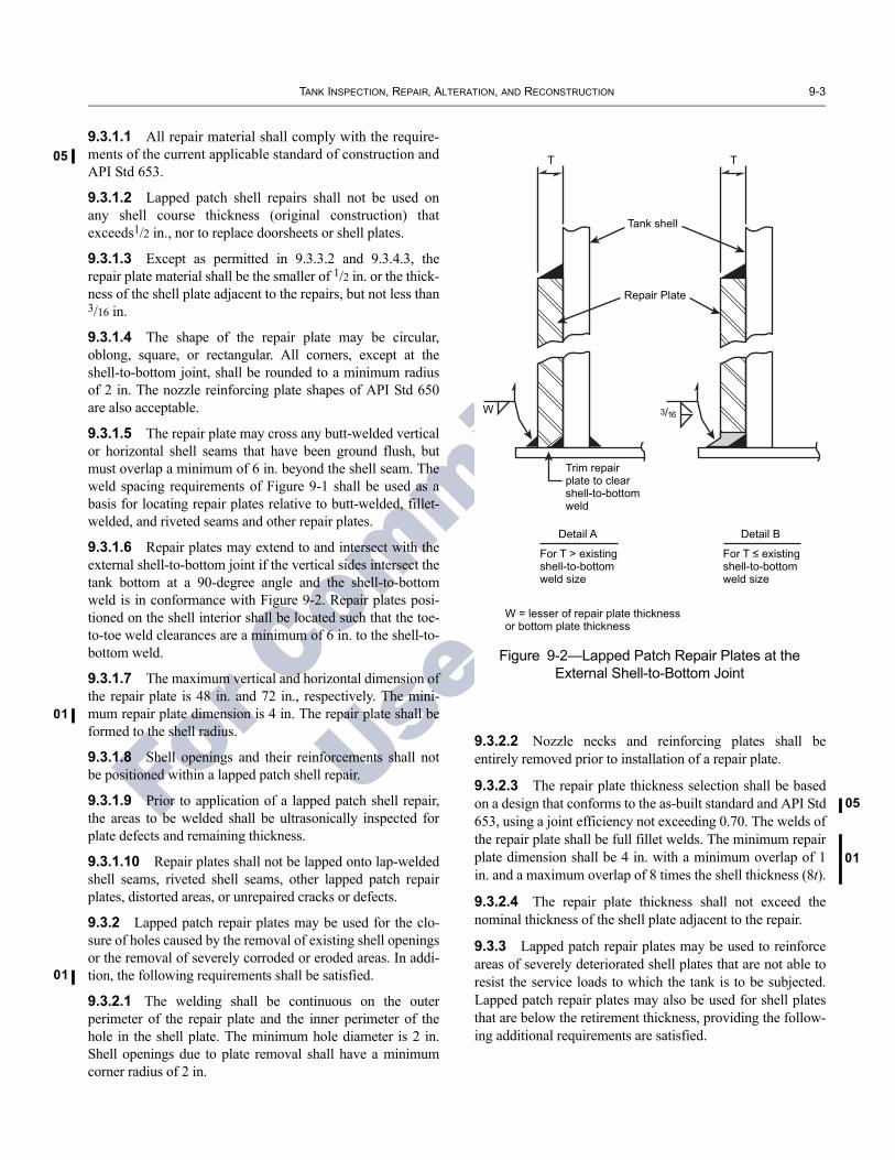
TANK INSPECTION, REPAIR, ALTERATION, AND RECONSTRUCTION 9-3
05
01
01
05
01
For C
ommittee
Use O
nly
9.3.1.1 All repair material shall comply with the require-ments of the current applicable standard of construction andAPI Std 653.
9.3.1.2 Lapped patch shell repairs shall not be used onany shell course thickness (original construction) thatexceeds1/2 in., nor to replace doorsheets or shell plates.
9.3.1.3 Except as permitted in 9.3.3.2 and 9.3.4.3, therepair plate material shall be the smaller of 1/2 in. or the thick-ness of the shell plate adjacent to the repairs, but not less than3/16 in.
9.3.1.4 The shape of the repair plate may be circular,oblong, square, or rectangular. All corners, except at theshell-to-bottom joint, shall be rounded to a minimum radiusof 2 in. The nozzle reinforcing plate shapes of API Std 650are also acceptable.
9.3.1.5 The repair plate may cross any butt-welded verticalor horizontal shell seams that have been ground flush, butmust overlap a minimum of 6 in. beyond the shell seam. Theweld spacing requirements of Figure 9-1 shall be used as abasis for locating repair plates relative to butt-welded, fillet-welded, and riveted seams and other repair plates.
9.3.1.6 Repair plates may extend to and intersect with theexternal shell-to-bottom joint if the vertical sides intersect thetank bottom at a 90-degree angle and the shell-to-bottomweld is in conformance with Figure 9-2. Repair plates posi-tioned on the shell interior shall be located such that the toe-to-toe weld clearances are a minimum of 6 in. to the shell-to-bottom weld.
9.3.1.7 The maximum vertical and horizontal dimension ofthe repair plate is 48 in. and 72 in., respectively. The mini-mum repair plate dimension is 4 in. The repair plate shall beformed to the shell radius.
9.3.1.8 Shell openings and their reinforcements shall notbe positioned within a lapped patch shell repair.
9.3.1.9 Prior to application of a lapped patch shell repair,the areas to be welded shall be ultrasonically inspected forplate defects and remaining thickness.
9.3.1.10 Repair plates shall not be lapped onto lap-weldedshell seams, riveted shell seams, other lapped patch repairplates, distorted areas, or unrepaired cracks or defects.
9.3.2 Lapped patch repair plates may be used for the clo-sure of holes caused by the removal of existing shell openingsor the removal of severely corroded or eroded areas. In addi-tion, the following requirements shall be satisfied.
9.3.2.1 The welding shall be continuous on the outerperimeter of the repair plate and the inner perimeter of thehole in the shell plate. The minimum hole diameter is 2 in.Shell openings due to plate removal shall have a minimumcorner radius of 2 in.
9.3.2.2 Nozzle necks and reinforcing plates shall beentirely removed prior to installation of a repair plate.
9.3.2.3 The repair plate thickness selection shall be basedon a design that conforms to the as-built standard and API Std653, using a joint efficiency not exceeding 0.70. The welds ofthe repair plate shall be full fillet welds. The minimum repairplate dimension shall be 4 in. with a minimum overlap of 1in. and a maximum overlap of 8 times the shell thickness (8t).
9.3.2.4 The repair plate thickness shall not exceed thenominal thickness of the shell plate adjacent to the repair.
9.3.3 Lapped patch repair plates may be used to reinforceareas of severely deteriorated shell plates that are not able toresist the service loads to which the tank is to be subjected.Lapped patch repair plates may also be used for shell platesthat are below the retirement thickness, providing the follow-ing additional requirements are satisfied.
T
Tank shell
Repair Plate
W 3/16
Trim repairplate to clearshell-to-bottomweld
T
Detail A
For T > existingshell-to-bottomweld size
Detail B
shell-to-bottomweld size
W = lesser of repair plate thicknessor bottom plate thickness
Figure 9-2—Lapped Patch Repair Plates at the External Shell-to-Bottom Joint

9-4 API STANDARD 653
05
05
For C
ommittee
Use O
nly
9.3.3.1 The selection of the repair plate thickness shall bebased on a design that conforms to the as-built standard andAPI Std 653, using a joint efficiency not exceeding 0.35. Theperimeter weld shall be a full fillet weld.
9.3.3.2 The repair plate thickness shall not exceed the shellplate thickness at the perimeter of the repair plate by morethan one-third, but no more than 1/8 in. The repair plate thick-ness shall not exceed 1/2 in.
9.3.3.3 The remaining strength of the deteriorated areasunder the repair plate shall not be considered as effective incarrying the calculated service or hydrotest loads.
9.3.4 Lapped patch repair plates may be used to repairsmall shell leaks, or minimize the potential from leaks fromseverely isolated or widely scattered pitting if the followingrequirements are satisfied.
9.3.4.1 The existing shell thickness, excluding the holesand pitting, meets the minimum acceptable shell thickness asdetermined by 4.3.2 and 4.3.3.
9.3.4.2 The repair plate is designed to withstand thehydrostatic pressure load between the repair plate and theshell assuming a hole exists in the shell using a joint effi-ciency of 0.35.
9.3.4.3 The repair plate thickness shall not exceed the shellplate thickness at the perimeter of the repair plate by morethan one-third, but no more than 1/8 in. The repair plate thick-ness shall be no thinner than 3/16 in. nor thicker than 1/2 in. Afull fillet perimeter weld is required.
9.3.4.4 This repair method shall not be used if exposure ofthe fillet welds to the product will produce crevice corrosionor if a corrosion cell between the shell plate and repair plate islikely to occur.
9.3.4.5 This repair method shall not be used to repair shellleaks if the presence of product between the shell plate andrepair plate will prevent gas freeing from the tank to performhot work.
9.3.4.6 The existing shell plate under the repair plate shallbe evaluated at each future inspection to ensure it satisfies therequirements of 9.3.4.1. If the existing shell plate thicknessdoes not satisfy 9.3.4.1 or the repair plate does not satisfy9.3.3, the area is to be repaired in accordance with 9.2 or 9.3.2.
9.4 REPAIR OF DEFECTS IN SHELL PLATE MATERIAL
The need for repairing indications such as cracks, gougesor tears (such as those often remaining after the removal oftemporary attachments), widely scattered pits, and corrodedareas discovered during an inspection of the tank shell shallbe determined on an individual case basis in accordance withSection 4. In areas where the shell plate thickness exceedsthat required by design conditions, it is permissible to grind
surface irregularities to a smooth contour so long as theremaining thickness is adequate for the design conditions.Where grinding to a smoothly contoured surface will resultin unacceptable shell plate metal thickness, the shell platemay be repaired by deposition of weld metal, followed byexamination and testing in accordance with 12.1.8. If moreextensive areas of shell plate require repair, use of buttwelded shell replacement plate or lap-welded patch plateshall be considered.
9.5 ALTERATION OF TANK SHELLS TO CHANGE SHELL HEIGHT
Tank shells may be altered by adding new plate material toincrease the height of the tank shell. The modified shellheight shall be in accordance with the requirements of thecurrent applicable standard and shall take into considerationall anticipated loadings such as wind and seismic.
9.6 REPAIR OF DEFECTIVE WELDS
Types of weld flaws and nonconformances that need repairare described in 9.6.1 through 9.6.4.
9.6.1 Cracks, lack of fusion, and rejectable slag and poros-ity that need repair shall be removed completely by gougingand/or grinding and the resulting cavity properly prepared forwelding.
9.6.2 Generally, it is not necessary to remove existing weldreinforcement in excess of that allowed by API Std 650 whendiscovered on an existing tank with a satisfactory service his-tory. However, if operating conditions are such that the exces-sive weld reinforcement may be deleterious (such as for afloating roof with flexible seals), consideration shall be givento repairing the welds by grinding.
9.6.3 Existing weld undercut deemed unacceptable basedon suitability for service considerations shall be repaired byadditional weld metal, or grinding, as appropriate.
9.6.4 Welded joints that have experienced loss of metal dueto corrosion may be repaired by welding.
9.6.5 Arc strikes discovered in or adjacent to welded jointsshall be repaired by grinding and/or welding. Arc strikesrepaired by welding shall be ground flush with the plate.
9.7 REPAIR OF SHELL PENETRATIONS
9.7.1 Repairs to existing shell penetrations shall be in com-pliance with API Std 650.
9.7.2 Reinforcing plates may be added to existing unrein-forced nozzles when deemed appropriate. The reinforcingplate shall meet all dimensional and weld spacing require-ments of API Std 650. See Figures 9-3A and 9-3B for accept-able details.
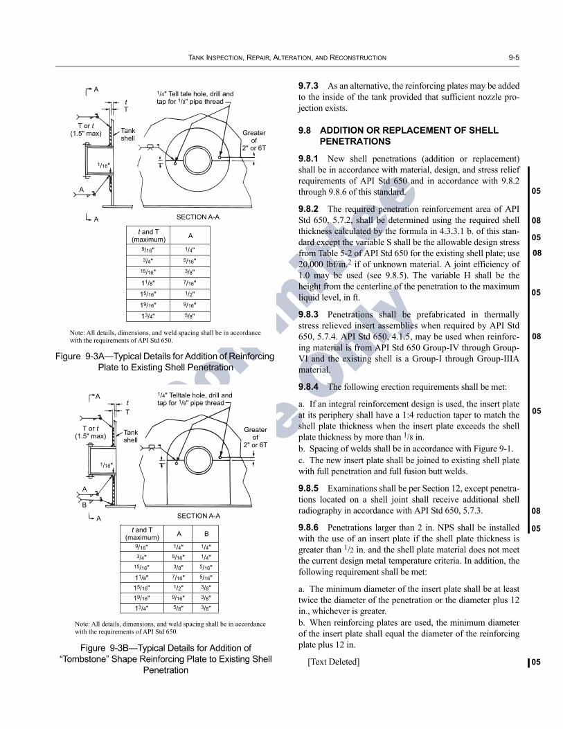
TANK INSPECTION, REPAIR, ALTERATION, AND RECONSTRUCTION 9-5
05
08
05
08
05
08
08
05
05
05
For C
ommittee
Use O
nly
9.7.3 As an alternative, the reinforcing plates may be addedto the inside of the tank provided that sufficient nozzle pro-jection exists.
9.8 ADDITION OR REPLACEMENT OF SHELL PENETRATIONS
9.8.1 New shell penetrations (addition or replacement)shall be in accordance with material, design, and stress reliefrequirements of API Std 650 and in accordance with 9.8.2through 9.8.6 of this standard.
9.8.2 The required penetration reinforcement area of APIStd 650, 5.7.2, shall be determined using the required shellthickness calculated by the formula in 4.3.3.1 b. of this stan-dard except the variable S shall be the allowable design stressfrom Table 5-2 of API Std 650 for the existing shell plate; use20,000 lbf/in.2 if of unknown material. A joint efficiency of1.0 may be used (see 9.8.5). The variable H shall be theheight from the centerline of the penetration to the maximumliquid level, in ft.
9.8.3 Penetrations shall be prefabricated in thermallystress relieved insert assemblies when required by API Std650, 5.7.4. API Std 650, 4.1.5, may be used when reinforc-ing material is from API Std 650 Group-IV through Group-VI and the existing shell is a Group-I through Group-IIIAmaterial.
9.8.4 The following erection requirements shall be met:
a. If an integral reinforcement design is used, the insert plateat its periphery shall have a 1:4 reduction taper to match theshell plate thickness when the insert plate exceeds the shellplate thickness by more than 1/8 in. b. Spacing of welds shall be in accordance with Figure 9-1.c. The new insert plate shall be joined to existing shell platewith full penetration and full fusion butt welds.
9.8.5 Examinations shall be per Section 12, except penetra-tions located on a shell joint shall receive additional shellradiography in accordance with API Std 650, 5.7.3.
9.8.6 Penetrations larger than 2 in. NPS shall be installedwith the use of an insert plate if the shell plate thickness isgreater than 1/2 in. and the shell plate material does not meetthe current design metal temperature criteria. In addition, thefollowing requirement shall be met:
a. The minimum diameter of the insert plate shall be at leasttwice the diameter of the penetration or the diameter plus 12in., whichever is greater.b. When reinforcing plates are used, the minimum diameterof the insert plate shall equal the diameter of the reinforcingplate plus 12 in.
[Text Deleted]
Figure 9-3A—Typical Details for Addition of Reinforcing Plate to Existing Shell Penetration
Figure 9-3B—Typical Details for Addition of “Tombstone” Shape Reinforcing Plate to Existing Shell
Penetration
A
A
A
Tt
T or t(1.5" max) Tank
shell
1/4" Tell tale hole, drill andtap for 1/8" pipe thread
Greaterof
2" or 6T
1/16"
SECTION A-A
9/16"3/4"
15/16"11/8"15/16"19/16"13/4"
1/4"5/16"3/8"
7/16"1/2"
9/16"5/8"
t and T(maximum) A
Note: All details, dimensions, and weld spacing shall be in accordancewith the requirements of API Std 650.
A
A
A
B
Tt
T or t(1.5" max) Tank
shell
1/4" Telltale hole, drill andtap for 1/8" pipe thread
Greaterof
2" or 6T
SECTION A-A
9/16"3/4"
15/16"11/8"15/16"19/16"13/4"
1/4"5/16"3/8"7/16"1/2"9/16"5/8"
t and T(maximum) A
1/4"1/4"
5/16"5/16"3/8"3/8"3/8"
B
Note: All details, dimensions, and weld spacing shall be in accordancewith the requirements of API Std 650.
1/16"

9-6 API STANDARD 653
05
05
08
08
08
01
01
05
For Committee
Use O
nly
9.9 ALTERATION OF EXISTING SHELL PENETRATIONS
9.9.1 Existing shell penetrations may be altered if thealtered details comply with the requirements of API Std 650,including the requirements for minimum reinforcing area andthe requirements for spacing of welds around connections.
9.9.2 When installing a new tank bottom above the existingbottom, it may be necessary to alter existing shell penetra-tions in the bottom course of a tank shell. If the new bottom isslotted through the tank shell several inches above the exist-ing bottom, the spacing between existing welds around pene-trations and the new bottom-to-shell weld may not complywith API Std 650 requirements. Options for altering the pene-trations and/or reinforcing plates are given in 9.9.2.1 through9.9.2.3.
9.9.2.1 The existing reinforcing plate may be trimmed toincrease the spacing between the welds provided that thealtered detail complies with the requirements of API Std 650.Care must be exercised during the trimming operation toavoid damaging the shell material beneath the reinforcingplate. The existing weld attaching the portion of the reinforc-ing plate to be removed shall be completely removed bygouging and grinding.
9.9.2.2 The existing reinforcing plate may be removed anda new reinforcing plate added except that reinforcement platereplacement is not permitted on existing stress relievedassemblies. If it is not known whether the assembly was ther-mally stressed relieved, then the alteration shall meet therequirements of API Std 650, Section 5.7.4. Care must beexercised when removing the existing reinforcing plate toavoid damaging the shell plate beneath the reinforcing plate.When the upper half of the existing reinforcing plate meetsall requirements of API Std 650, it can be left in place withapproval of the purchaser. In this case, only the lower half ofthe existing reinforcing plate need be removed and replacedwith the new one. The existing upper half of the reinforcingplate and the new lower section shall be provided with new atell tale hole, if needed, or drilled hole, and a welded pipecoupling for the pneumatic test. The shell plate thicknessunder the tell tale hole or drilled hole shall be checked afterdrilling and the thickness shall not be less than 1/2 tmin, as cal-culated in 4.3.3.1, plus any required corrosion allowance. Thewelds to be replaced around the perimeter of the reinforcingplate and between the reinforcing plate and neck of the pene-tration shall be completely removed by gouging and grinding.The new reinforcing plate shall be in accordance with Figure9-3A. If required to maintain weld spacing, a tombstoneshaped reinforcing plate may be used. (See Figure 9-3B).
9.9.2.3 The existing penetration may be moved by cuttingthe section of the shell containing the fitting and reinforcingplate, and raising the entire assembly to the correct elevation(see Figure 9-4).
9.9.3 Any components of the penetration (neck, flange, andreinforcing plate) that are in serviceable condition afterremoval may be reused.
9.9.4 A new bottom may be installed through an existingtombstone reinforcing plate, provided all weld spacing andreinforcement requirements, as specified in API Std 650, aremet. One of the following methods shall be used:
a. Remove only that portion of the existing reinforcing platenecessary to weld and test the new bottom-to-shell weld. Thelower edge of the reinforcing plate shall be cut reasonablystraight and horizontal and beveled to facilitate welding.Refer to Figure 9-5A for weld joint details. b. Bevel the shell from the inside to allow for a full pene-tration weld between the bottom and shell. This methodshall only be used on tanks where the annular plate or bot-tom sketch plate thickness is equal to or greater than10 mm (3/8 in.). This weld detail shall be used along thefull width of the reinforcing plate and shall extend a mini-mum of 25 mm (1 in.) beyond the edges of the reinforcingplate. Once beyond the reinforcing plate, the full penetra-tion weld shall tie in to the outside shell-to-bottom fillet
Figure 9-4—Method for Raising Shell Nozzles
Filler platesame thicknessas shell
Old bottom
6" radius+
+
Spacing per 5.7.3of API Standard650,or as permittedper 9.10.2.1.5
New bottom
6" radius
Old bottom Reinforcing plate
Top ofproposednew bottom
AFTER RAISING
BEFORE RAISING
Cut lines in shell plate

TANK INSPECTION, REPAIR, ALTERATION, AND RECONSTRUCTION 9-7
08
08
03
08
For C
ommittee
Use O
nly
weld to create a ‘water stop’ and then transition to the typ-ical shell-to-bottom weld detail. Refer to Figure 9-5B forweld joint details. c. The lower portion of the existing reinforcing plate may beremoved and re-installed after the new shell-to-bottom weld iscomplete. The existing reinforcing plate shall be cut at the hor-izontal centerline of the nozzle. Tell-tale holes are required inboth parts of the reinforcing plate. (See Figure 9-3B.)d. The existing reinforcing plate may be removed, modifiedand re-installed after the new shell-to-bottom weld is com-plete. (See Figure 9-3B.)
Notes:1. Options c and d are not permitted on existing post weld heat
treated nozzles or man-ways. 2. To minimize damage to the shell plate such that repairs can be
made, care must be exercised when removing the existing rein-forcing plate.
9.10 REPAIR OF TANK BOTTOMS
9.10.1 Repairing a Portion of Tank Bottoms
9.10.1.1 General Repair Requirements
The use of welded-on patch plates for repairing a portionof uniformly supported tank bottoms is permitted within thelimitations given in this section and 9.10.1.2. Refer to Figure9-6 for acceptable details for welded-on patch plates.
a. The minimum dimension for a welded-on patch plate thatoverlaps a bottom seam or existing patch is 12 in. Thewelded-on patch plate may be circular, oblong, or polygonalwith rounded corners.b. A welded-on patch plate smaller than 12 in. in diameter ispermitted if: it is equal to or exceeds 6 in. in diameter; it doesnot overlap a bottom seam; it is not placed fully or partiallyover an existing patch; and it extends beyond the corrodedbottom area, if any, by at least 2 in.c. Welded-on patch plates shall not be placed over areas ofthe tank bottom that have global dishing, local dishing(except as allowed by 9.10.1.1 d), settlement, or distortiongreater than the limits of Appendix B.
Note: If the tank is still undergoing settlement, the addition ofwelded-on patch plate may not be advisable.
d. A welded-on patch plate may be placed over a mechanicaldent or local dishing if: its unsupported dimension does notexceed 12 in. in any direction; it is at least 1/4 in. thick; it is atleast as thick as the existing bottom; and does not overlapseams nor other patches, except for tanks designed in accor-dance with API Std 650, Appendix M, which shall havewelded-on patch plates at least 3/8 in. thick.
[Text deleted.]e. These repairs are permanent repairs subject to an on-goinginspection and maintenance program.
Figure 9-5A—Details for Installing a New Bottom Through an Existing Tombstone Reinforcing Plate
Figure 9-5B—Details for Installing a New Bottom Through an Existing Tombstone Reinforcing Plate
Centerline of nozzle
Tank shell
Fillet weld sizes perAPI 650, 5.1.5.7
Not less than the greater of T/2or the fillet size determinedfrom API 650 5.1.5.7
New bottom orannular plate
Existing tombstonereinforcing plate
See note 1
Tt
Existing shell penetration(existing welds not shown)
Notes: 1. See API 650 Table 5-6 for weld spacing requirements. 2. All welds shown shall be individually examined to API 650 7.2.4.
Centerline of nozzle
Tank shell
Full penetrationweldFillet weld sizes per
API 650, 5.1.5.7
New bottom orannular plate ≥ 9.5mm (3/8")
Existing tombstonereinforcing plate
See note 1
Existing shell penetration(existing welds not shown)
Notes:1. See API 650 Table 5-6 for weld spacing requirements.2. All welds shown shall be individually examined to API 650 7.2.4.

9-8 API STANDARD 653
05
01
05
8
For C
ommittee
Use O
nly
Typi
cal “
tom
bsto
ne-s
hape
d”w
elde
d-on
pla
tes
2 in
.m
inim
umra
dius
A AL1
L2N
ote
3N
ote
3N
ote
2
2 in
.(m
in.)
6 in
.(m
in.)
2 in
. (m
in.)
2 in
. (m
in.)
12 in
. (m
in.)
12 in
.(m
in.)
2 in
. (m
in.)
see
note
4B
otto
m s
eam
Bot
tom
sea
m
Thre
e-pl
ate
lap
(see
not
e 5)
12 in
. (m
in.)
6 in
. (m
in.)
45°
(min
.)
She
ll pl
ate
3 in
.
Crit
ical
zone
Wel
ded-
on p
atch
pla
te(1
/ 4 in
. max
imum
thic
knes
s in
the
criti
cal z
one)
She
ll
Bot
tom
pla
te o
r ann
ular
pla
te ri
ng
Sect
ion
A-A
Plan
Vie
wN
otes
:1.
Dim
ensi
ons g
iven
are
from
toe
of fi
llet w
elds
or t
o ce
nter
line
of b
utt-w
eld
an
d al
so a
pply
to n
ew-to
-exi
stin
g w
elds
.2.
Min
imum
dis
tanc
e be
twee
n tw
o w
elde
d-on
pat
ch p
late
s in
the
cr
itica
l zon
e sh
all b
e on
e ha
lf of
the
less
er o
f L1
or L
2.3.
The
max
imum
dim
ensi
on a
long
the
shel
l for
wel
ded-
on p
atch
plat
es in
the
criti
cal z
one
is 2
4 in
ches
.4.
Whe
n th
e ed
ge o
f a w
elde
d-on
pat
ch p
late
is a
ppro
xim
atel
y
para
llel t
o a
botto
m se
am, t
he e
dge
shal
l be
held
at l
east
2 in
ches
from
wel
d se
am.
5. P
atch
es o
ver t
hree
-pla
te la
ps sh
all e
xten
d a
min
imum
of 1
2 in
ches
in a
ll
dire
ctio
ns a
long
all
laps
bey
ond
the
thre
e-pl
ate
lap.
6. T
hese
rule
s app
ly to
but
t-wel
ded
botto
ms,
whe
re a
pplic
able
.
12 in
.
(min
)
Thr
ee-p
late
lap
(see
not
e 5)
2 in
. (m
in)
12 in
. (m
in)
Bot
tom
cor
rode
dar
ea,
if an
y
For w
elde
d-on
pat
ch p
late
s le
ss th
an12
in. d
imen
sion
, see
9.1
0.1.
1b.
2 in
.(m
in.)
Thr
ee-p
late
lap
Figu
re9-
6—Ty
pica
l Wel
ded-
on P
atch
Pla
tes
on T
ank
Botto
m P
late
s
0

TANK INSPECTION, REPAIR, ALTERATION, AND RECONSTRUCTION 9-9
08
08
03
05
08
05
05
05
05
08
05
For C
ommittee
Use O
nly
9.10.1.2 Repairs within the Critical Zone
The use of welded-on patch plates is permitted for repair-ing a portion of tank bottoms within the critical zone (see3.12 for definition) provided 9.10.1.1 requirements and thefollowing additional requirements are met.
a. Maximum plate thickness for welded-on patch plateswithin the critical zone is 1/4-in. and must meet the toughnessrequirements of API Std 650, Section 4.2.9. b. When a welded-on patch plate is within 6 in. of the shell,the welded-on patch plate shall be tombstone shaped. Thesides of the tombstone shaped welded-on patch plate shallintersect the shell-to-bottom joint at approximately 90degrees.c. Perimeter welds on welded-on patch plates within the crit-ical zone shall be two-pass, minimum, and examined per12.1.1.3 and 12.1.7.2. d. Installation of a welded-on patch plate by butt-welding toan adjacent existing patch is not permitted in the critical zone.e. Welded-on patch plates over existing patches are notallowed in the critical zone.f. The bottom plate under the perimeter of a welded-on patchplate shall meet the thickness requirements in 4.4.
Note: The bottom plate thickness at the attachment weld must be atleast 0.1-in. thick before welding the welded-on patch plate to thebottom plate. Refer to API Publ 2207 for further information.
9.10.1.2.1 No welding or weld overlays are permittedwithin the critical zone except for the welding of: widely scat-tered pits (see 4.3.2.2), pinholes, cracks in the bottom plates,the shell-to-bottom weld, welded-on patch plates, or wherethe bottom plate welded to the shell is being replaced.
9.10.1.2.2 A welded-on patch plate shall not be used if thecovered bottom plate minimum remaining thickness at the toeof the internal shell-to-bottom weld will be less than the min-imum thickness required by 4.4.7 or 4.4.8 at the next internalinspection.
9.10.1.2.3 Welded-on patch plates are not permitted in thecritical zone on a tank bottom with an operating temperatureexceeding 200°F for carbon steel or 100°F for stainless steel.
9.10.1.2.4 If more extensive repairs are required withinthe critical zone than those listed in 9.10.1.2, the bottomplate welded to the shell shall be cut out and a new plateshall be installed. Weld spacing requirements shall be inaccordance with 9.10.2.3, and API Std 650, 5.1.5.4 and5.1.5.5. The shell-to-bottom weld shall be removed andreplaced for a minimum distance of 12 in. on each side of thenew bottom plate.
9.10.1.3 The use of welded-on patch plates that do notmeet the requirements of 9.10.1.1 or 9.10.1.2 is permitted ifthe repair method has been reviewed and approved by anengineer experienced in storage tank design in accordancewith API Std 650. The review shall consider brittle fracture,
stress due to settlement, stress due to shell-bottom discontinu-ity, metal temperature, fracture mechanics, and the extent andquality of nondestructive examination.
9.10.1.4 Unacceptable indications such as cracks,gouges, tears, and corroded areas discovered in bottomplates, located outside the critical zone, may be repaired bydeposition of weld metal followed by examination and test-ing in accordance with 12.1.7.3. Surface irregularities andcontamination within the area to be repaired shall beremoved before welding.
9.10.1.5 The repair of sumps located within the criticalzone shall be in accordance with 9.10.1.2.
9.10.1.6 The repair of corroded plates in the critical zone islimited to pit welding or overlay welding as noted in this sec-tion. The weld repair of bottom plate corrosion is permitted ifall of the following conditions are satisfied.
a. The sum of the pit dimensions along an arc parallel to theshell-to-bottom joint does not exceed 2 in. in an 8-in. length.b. There must be sufficient remaining bottom plate thicknessfor completion of a sound weld and to avoid burn-through.The minimum acceptable bottom plate thickness for weldrepairs is 0.10 in. A lesser thickness is permitted for weldrepairs only if reviewed and approved by an engineer experi-enced in storage tank design and repair.c. All weld repairs shall be ground flush with the surround-ing plate material and be examined in accordance with12.3.2.4.
9.10.2 Replacement of Tank Bottom Plates
9.10.2.1 Requirements governing the installation of areplacement bottom over an existing bottom are given in9.10.2.1.1 through 9.10.2.1.5.
9.10.2.1.1 Suitable noncorrosive material cushion such assand, gravel, or concrete shall be used between the old bot-tom and the new bottom.
9.10.2.1.2 The shell shall be slotted with a uniform cutmade parallel to the tank bottom. The cut edges in the slotshall be ground to remove all slag and burrs from cuttingoperations. The new bottom plate shall extend outside theshell as required by API Std 650. All rules for weld spacingshall be followed.
9.10.2.1.3 Voids in the foundation below the old bottomshall be filled with sand, crushed limestone, grout, or concrete.
9.10.2.1.4 Except as permitted in 9.10.2.7, existing shellpenetrations shall be raised or their reinforcing plates modi-fied if the elevation of the new bottom results in inadequatenozzle reinforcement details (see Figure 9-3B and API 650,5.7.2) or if the weld space requirements given in API Std 650,5.7.3 are not met.
[Text Deleted]

9-10 API STANDARD 653
05
05
05
05
05
05
05
08
05
05
03
08
For C
ommittee
Use O
nly
9.10.2.1.5 For floating roof tanks, the new bottom profilemust keep the roof level when it is resting on its support legs.The levelness of the floating roof can be adjusted by chang-ing the length of the support legs. The support legs can eitherremain the same length to maintain the original height abovethe bottom or be shortened by the same amount as the thick-ness of the cushion and new bottom plate.
9.10.2.2 New bearing plates for floating roof support legsand for fixed roof support columns shall be installed. Forinternal floating roofs with aluminum supports, new austen-itic stainless steel or acceptable non-metallic (e.g. Teflon®)spacers shall be added to isolate supports from the carbonsteel bottom.
9.10.2.3 When removing an existing tank bottom, the tankshell shall be separated from tank bottom either by:
a. Cutting the shell parallel to the tank bottom a minimum of1/2 in. above the bottom-to-shell weld (cut line B-B as shownin Figure 10-1), orb. Removing the entire shell-to-bottom attachment weld,including any penetration and heat affected zone by suitablemethods such as arc gouging and/or grinding.
All arc-gouged areas of the tank shell-to-bottom weld shallbe magnetic particle examined, and defective areas repairedand re-examined.
9.10.2.4 Installation of a new tank bottom, after removal ofthe existing tank bottom, shall meet all requirements of APIStd 650. Except as permitted in 9.10.2.7, existing shell pene-trations shall be raised or their penetration reinforcing platesmodified if the elevation of the new bottom results in inade-quate nozzle reinforcement (see Fig. 9-3B and API 650, 5.7.2)or if the weld spacing requirements given in API Std 650,5.7.3 are not met. For tanks with shell plate of unknown tough-ness as defined in Section 3, new weld joints in the bottom orannular ring shall be spaced at least the greater of 3 in. or 5tfrom existing vertical weld joints in the bottom shell course,where t is the thickness of the bottom shell course, in inches.
9.10.2.5 Replacement of portions of an existing tank bot-tom (entire rectangular plates or large segments of plates) notwithin the critical zone (see 3.12 for definition) are permittedunder the same rules that govern installation of bottoms innew tank construction per API Std. 650.
9.10.2.6 The following shall be considered for tanks withcathodic protection and under-bottom leak detection:
a. For tanks having cathodic protection (CP) installed underthe existing bottom, consideration shall be given to removalof the entire bottom and unused dead shell to prevent shield-ing of CP current to the new bottom. Removal of the oldbottom is also important in preventing galvanic corrosion(refer to API RP 651). Where this is possible, removal of theentire old bottom, except the unused dead shell and not more
than 18 in. of bottom annulus attached to the shell, shall beconsidered. b. Consideration shall be given to installing under-bottomleak detection at this time (such as a RPB) to contain andchannel any bottom leak to a location where it can readily beobserved from outside of the tank. See 4.4.5 and Footnote 5.
9.10.2.7 For tanks constructed from materials having50,000 lbf/in.2 yield strength or less, existing shell penetra-tions need not be raised if the following conditions are met:
a. For reinforced penetrations, including low-types, a mini-mum of 4 in. shall be maintained between the shell-to-bottomweld toe and the nearest penetration attachment weld toe(reinforcing plate periphery weld, or nozzle neck weld to lowtype reinforcing plate and shell welds).b. For self-reinforced penetrations, the greater of 3 in. or 21/2 tshall be maintained between the shell-to-bottom weld toe andthe nearest penetration attachment weld toe.c. The shell-to-bottom weld is to be welded with low hydro-gen electrodes and with welding procedures that are designedto limit distortion and residual stress.d. The toes of the welds shall be blend-ground to minimizestress concentrations as follows:
i. For circular reinforcing plates, blend-grind theperiphery attachment weld from the “four o'clock”position to the “eight o'clock” position. Blend-grindthe inside and outside of the shell-to-bottom weld aminimum of one penetration diameter length on eitherside of the penetration centerline.
ii. For diamond-shaped reinforcing plates, blend-grindthe lower horizontal length of the diamond shapedattachment weld. Blend-grind the inside and outsideof the shell-to-bottom weld a minimum of one pene-tration diameter length on either side of thepenetration centerline.
iii. For low-type penetrations, blend-grind the nozzleattachment weld (shell and reinforcing plate) from the“four o'clock” position to the “eight o'clock” position.Blend-grind the inside and outside of the shell-to-bot-tom weld a minimum of one penetration diameterlength on either side of the penetration centerline.
e. The blend-ground lengths of welds listed in 9.10.2.1.7dshall be magnetic particle examined before and after hydro-static test.
9.10.3 Additional Welded-on Plates
9.10.3.1 If other welded-on plates such as wear, isolation,striker, and bearing plates, are to be added to tank bottoms,they shall be installed in accordance with 9.10.1, and exam-ined in accordance with 12.1.7. For these additional welded-on plates, if the lap weld spacing requirements as set forth inFigure 9-6 are not met, magnetic particle (MT) or liquid pen-etrant (PT) examination is required for the exposed welds or

TANK INSPECTION, REPAIR, ALTERATION, AND RECONSTRUCTION 9-11
03
08
08
08
08
08
08
For C
ommittee
Use O
nly
portions of welds failing to meet minimum spacing criteria.See Section 12 for acceptance requirements.
9.10.3.2 Welded-on plates that fall within the critical zone(see 3.12 for definition) shall be installed in accordance with9.10.1.2 and comply with all of its requirements.
9.11 REPAIR OF FIXED ROOFS
9.11.1 Repairs
9.11.1.1 Roof repairs involving tank venting shall be madesuch that normal and emergency venting meet the require-ments of API Std 650, Section 5.8.5.
9.11.1.2 Roof repairs involving modification of the roofstructure and the frangible joint (if applicable) shall be incompliance with the requirements of API Std 650, Section5.10.
9.11.2 Supported Cone Roofs
9.11.2.1 The minimum thickness of new roof plates shallbe 3/16 in. plus any corrosion allowance as specified in therepair specifications. In the event roof live loads in excess of25 lbf/ft2 are specified (such as insulation, operating vacuum,high snow loads), the plate thickness shall be based on analy-sis using the allowable stresses in conformance with API Std650, Section 5.10.3 (see 9.11.2.2).
9.11.2.2 The roof supports (rafters, girders, columns, andbases) shall be repaired or altered such that under design con-ditions the resulting stresses do not exceed the stress levelsgiven in Section 5.10.3 of API Std 650.
9.11.3 Self-Supporting Roofs
9.11.3.1 The nominal thickness of new roof plate shall be3/16 in. or the required plate thickness given in API Std 650,Sections 5.10.5 or 5.10.6, plus any specified corrosion allow-ance, whichever is greater.
9.11.3.2 The details of the roof-to-shell junction shallmeet the requirements of API Std 650, Sections 5.10.5,5.10.6, or Appendix F, as applicable, for the intended ser-vice.
9.12 REPAIR OF FLOATING ROOFS
9.12.1 External Floating Roofs
Any method of repair is acceptable that will restore theroof to a condition enabling it to perform as required.
9.12.2 Internal Floating Roofs
Repairs to internal floating roofs shall be made in accor-dance with the original construction drawings, if available. Ifthe original construction drawings are not available, the roof
repairs shall be in compliance with the requirements of APIStd 650, Appendix H.
9.12.3 Repair of Leaks In Pontoons
All leaks in pontoons or compartments of double deckfloating roofs shall be repaired by rewelding the leakingjoints and/or use of patch plates.
9.13 REPAIR OR REPLACEMENT OF FLOATING ROOF PERIMETER SEALS
9.13.1 Primary Seals
Rim-mounted primary shoe seals and toroidal seal systemscan be removed, repaired, or replaced. To minimize evapora-tion losses and reduce potential hazard to the workers, nomore than one-fourth of the roof seal system should be out ofan in-service tank at one time. Temporary spacers to keep theroof centered shall be used during the repairs. Primary sealsystems mounted partly or fully below the bolting bar or topof the rim usually cannot be reached to allow removal in ser-vice. In this case, in-service repairs are limited to replacementof the primary seal fabric.
9.13.2 Secondary Seals
Rim-mounted and shoe-mounted secondary seals may bereadily installed, repaired, or replaced while the tank is inservice.
9.13.3 Seal-To-Shell Gap
Repair and other corrective actions to maintain seal-to-shell gap requirements, include:
a. Adjusting the hanger system on primary shoe seals, andadding foam filler in toroidal seals.b. Increasing the length of rim mounted secondary seals inthe problem area.c. Replacing all or part of the primary seal system along withpossible installation of a rim extension for a secondary seal.This step shall be taken only after checking the annular spacevariation at several levels from low pump out to high liquidlevel.
9.13.4 Mechanical Damage
Damaged parts shall be repaired or replaced. Prior to tak-ing this action, the cause of the damage shall be identified andcorrected. Buckled parts shall be replaced, not straightened.Torn seal fabric shall be replaced.
9.13.5 Deterioration of Seal Material
Material deterioration results from wear and corrosion onmetallic elements, and chemical and weather deterioration

9-12 API STANDARD 653
0508
08
05
08
08
05
For C
ommittee
Use O
nly
of seal fabric. The service life and inspection informationshall be used to determine whether a change of material iswarranted.
9.13.6 Installation of Primary and Secondary Seals
9.13.6.1 The replacement or addition of primary and sec-ondary seals shall be in accordance with the recommenda-tions of the seal manufacturer. In addition, the finalinstallation shall comply with all applicable jurisdictions.
9.13.6.2 If the roof rim thickness is less than 0.10-in. thick,it shall be replaced. The new roof rim shall be 3/16-in. thick-ness, minimum.
9.14 HOT TAPS
9.14.1 General
9.14.1.1 The requirements given herein cover the installa-tion of radial hot tap connections on existing in-service tanks.Hot taps are not permitted on shell material requiring thermalstress relief as specified in API Std 650, 5.7.4.
a. For tank shell plates of recognized toughness, as definedin Section 3, the connection size and shell thickness limita-tions are shown in Table 9-1.b. For tank shell plates of unknown toughness, as defined inSection 3, the following limitations apply.
1. Nozzles shall be limited to a maximum diameter of4 in. NPS.
2. The shell plate temperature shall be at or above theminimum shell design metal temperature for the entire hottapping operation.
3. All nozzles shall be reinforced. The reinforcementshall be calculated per API Std 650, 5.7.2. The minimumthickness of the reinforcing plate shall be equal to the shellplate thickness, and the minimum reinforcing plate diame-ter shall not be less than the diameter of the shell cutoutplus 2 in.
4. The maximum height of tank liquid above the hot taplocation during the hot tapping operation shall be suchthat the hydrostatic tank shell stress is less than 7,000 lbf/in.2 at the elevation of the hot tap.
9.14.1.2 The minimum height of tank liquid above thehot tap location shall be at least 3 ft during the hot tappingoperation.
9.14.1.3 Welding shall be done with low hydrogen elec-trodes.
9.14.1.4 Hot taps are not permitted on the roof of a tank orwithin the gas/vapor space of the tank.
9.14.1.5 Hot taps shall not be installed on laminated orseverely pitted shell plate.
9.14.1.6 Hot taps are not permitted on tanks where the heatof welding may cause environmental cracking (such as caus-tic cracking or stress corrosion cracking).
9.14.2 Hot Tap Procedures
A hot tap procedure specific to carrying out the work shallbe developed and documented. The procedure shall includethe practices given in API Publ 2201.
9.14.3 Preparatory Work
9.14.3.1 Minimum spacing in any direction (toe-to-toe ofwelds) between the hot tap and adjacent nozzles shall beequivalent to the square root of RT where R is the tank shellradius, in inches, and T is the shell plate thickness, in inches.
9.14.3.2 Shell plate thickness measurements shall be takenat a minimum of four places along the circumference of theproposed nozzle location.
9.14.4 Material Limitations
Only hot tap steels of recognized toughness, as defined inSection 3, unless the additional requirements of 9.14.1.1bare met.
9.14.5 Installation Procedure
9.14.5.1 Pipe nozzles shall be cut to the contour of theshell and beveled from the outside for a full penetration weld(see Figure 9-7). The nozzle neck-to-shell weld shall beexamined in accordance with 12.1.2.3.
9.14.5.2 After the pipe is welded, the reinforcing plateshall be installed either in one piece or two pieces with hori-zontal weld. The reinforcing plate to nozzle shall be installedwith a full penetration weld. Care shall be taken to limit theheat input to the welds.
9.14.5.3 After the reinforcing plate has been welded to theshell and nondestructive examination performed, the pad
Table 9-1—Hot Tap Connection Sizes and Shell Plate Thicknesses
Connection Size, NPS(in.)
Minimum ShellPlate Thickness
(in.)
≤ 6 3/16
≤ 8 1/4
≤ 14 3/8
≤ 18 1/2

TANK INSPECTION, REPAIR, ALTERATION, AND RECONSTRUCTION 9-13
8
8
8
8
For C
ommittee
Use O
nly
Figure 9-7—Hot Tap for Tanks (See Note 1)
Flange, Class 150W.N. or S.O.
Reinforcing plate (T = t )rolled to outside radiusof tank shell
Pipe nozzle, Schd extra strong
See Detail a
t
T
T
Grind out root andseal weld fornozzle size 10 in. NPSand larger
1/4 in.min
HOT TAP ASSEMBLY
DETAIL a
REINFORCING PLATE DETAIL(See Notes 1, 2)
12 in. min. Do
Verticalweld
Horizontal weld ifreinforcing plateis in two pieces
Spacing perAPI Std 650, Section 5.7.3
Horizontal weld
1 in. (typ.)
Equ
al
Equ
al
Notes:1. Refer to 12.1 for nondestructive examination requirements.2. Reinforcing plate dimensions are as given in API 650, Table 5-6.
1/4 in. tell tale hole,drill and tap for1/8-in. pipethread
0
0
0
0
9-14 API STANDARD 653
08
08
08
For C
ommittee
Use O
nly
shall be pneumatically tested by the procedure described inAPI Std 650, Section 7.3.4. After the valve has been installedon the flange, a pressure test at least 1.5 times the hydrostatichead shall be performed on the nozzle prior to mounting thehot tap machine, which shall be bolted to the valve. Therequired pressure for the pressure test shall be at least thevalue computed by the following formula:
where
H2 = Height of tank shell (in.).
G = Specific gravity of product stored, as specifiedby purchaser. The specific gravity shall not beless than 1.0.
γw = Density of water (lbf/in.3).
9.14.5.4 A qualified operator shall operate the hot tapmachine and cut the hole in the tank following the hot tapmachine manufacturer’s procedures.
P psi( ) 1.5H2Gγw=

01
08
01
For C
ommittee
Use O
nly
SECTION 10—DISMANTLING AND RECONSTRUCTION
10.1 GENERAL
10.1.1 This section provides procedures for dismantling and reconstructing existing welded tanks that are to be relo-cated from their original site.
10.1.2 Hydrostatic testing requirements, nondestructive examination requirements, and acceptance criteria for the quality of welds for reconstructed tanks are specified in Section 12.
10.1.3 All reconstruction work must be authorized by the authorized inspector or an engineer experienced in storage tank design, prior to commencement of the work by a recon-struction organization (see 3.25). The authorized inspector will designate inspection hold points required during the reconstruction process and minimum documentation to be submitted upon job completion.
10.1.4 The authorized inspector or an engineer experi-enced in storage tank design shall approve all reconstruction work at the designated hold points and after reconstruction has been completed in accordance with the requirements of this standard.
10.2 CLEANING AND GAS FREEING
The tank shall be cleaned and gas-freed prior to com-mencement of dismantling.
10.3 DISMANTLING METHODS
10.3.1 General
Roof, shell, and bottom plates may be cut into any size pieces that are readily transportable to the new site for recon-struction.
10.3.2 Bottoms
10.3.2.1 Bottom plates that will be reused shall be cut by deseaming of lapwelds; or by cutting alongside of the remain-ing welds at a minimum of 2 in. away from existing welds, except where cuts cross existing weld seams.
10.3.2.2 If the bottom is to be used, one of the following methods is acceptable:
a. The bottom plates may be cut from the shell along a line A-A and line B-B shown in Figure 10-1, scrapping the welds and the bottom plate directly attached to the shell.b. If the entire bottom is to be reused, the bottom may be cut from the shell on the line C-C leaving the shell with part of the bottom attached.
c. If the tank has an existing butt-welded annular ring, this ring can be left attached to the shell or removed from the shell by cutting out along line B-B or otherwise removing the existing shell to annular ring welds.
10.3.3 Shells
10.3.3.1 Tank shell plates may be dismantled using one of the following methods or a combination thereof:
a. Any shell ring may be dismantled by cutting out existing weld seams and the heat affected zone (HAZ) of the weld. For the purpose of this method, the minimum HAZ to be removed will be 1/2 of the weld metal width or 1/4 in., which-ever is less, on both sides of the weld seam.b. Any shell ring 1/2 in. thick or thinner may be dismantled by cutting through the weld without removing the HAZ.c. Shell rings may be dismantled by cutting vertical and/or horizontal cuts through the shell a minimum of 6 in. away from existing welds, except where cuts cross existing welds.
10.3.3.2 Shell stiffening rings, including wind girders and top angles, may be left attached to the shell plates or may be removed by cutting at the attachment welds. The area where temporary attachments are removed shall be ground flush with the shell plate.
10.3.3.3 The shell shall be cut from the bottom plate along line B-B as shown in Figure 10-1. The existing shell-to-bot-tom weld connection shall not be reused unless the entire bot-tom is to be reused intact.
10.3.4 Roofs
10.3.4.1 Roof plates shall be cut by deseaming of lap welds, or by cutting alongside of the remaining welds at a minimum of 2 in. away from existing welds, except where cuts cross existing welds.
10.3.4.2 Roof supporting structures shall be dismantled by removing bolts (if bolted) or deseaming the structural attach-ment welds.
10.3.5 Piece Marking
10.3.5.1 Shell, bottom, and roof plates shall be marked prior to dismantling for ready identification and placement when the tank is reconstructed. Marking material shall be of a durable type. Drawings showing piece mark locations are also a useful adjunct.
10.3.5.2 A minimum of two sets of matching center punch marks shall be located on the top and bottom edges of each shell plate to facilitate proper alignment during reconstruction.
10-1

10-2 API STANDARD 653
08
05
05
For C
ommittee
Use O
nlyFigure 10-1—Tank Shell and Bottom Cut Locations
Shell
B B
C
CBottomplate
1/2" min.
1/2" min.
A
A
12" min.
10.4 RECONSTRUCTION
10.4.1 General
10.4.1.1 The foundation for the reconstructed tank shall meet the construction tolerances given in 10.5.6.
10.4.1.2 Temporary attachments shall be removed, and the attachment area ground flush with the plate surface.
10.4.2 Welding
10.4.2.1 Provisions shall be made during the reconstruc-tion of a tank to ensure that weld spacing requirements of Figure 9-1 are maintained. New vertical joints in adjacent shell courses, made in accordance with 10.3.3.1, shall not be aligned but shall be offset from each other a minimum dis-tance of 5t, where t is the plate thickness of the thicker course at the point of the offset.
10.4.2.2 Tanks and their structural attachments shall be welded in accordance with the processes specified in API Std 650 and the requirements of 10.4.2.3 through 10.4.2.11.
10.4.2.3 No welding of any kind shall be performed when the surfaces of the parts to be welded are wet from rain, snow, or ice; when rain or snow is falling on such surfaces; or dur-ing periods of high winds unless the welder and the work are properly shielded. No welding of any kind shall be performed when the temperature of the base metal is less than 0°F. When the temperature of the base metal is between 0°F and 32°F or the thickness is in excess of 1 in., the base metal within 3 in. of the place where welding is to be started shall be heated to a
temperature warm to the hand (approximately 140°F) before welding. (See 10.4.4.3 for preheat requirements for shell platesover 11/2-in. thick.)
10.4.2.4 Each layer of weld metal of multilayer welding shall be cleaned of slag and other deposits before the next layer is applied.
10.4.2.5 The edges of all welds shall merge with the sur-face of the plate without a sharp angle. Maximum permissi-ble weld undercut shall be in accordance with API Std 650, Sections 7.2.1.4 and 8.5.1.b.
10.4.2.6 The reinforcement of the new welds on all butt joints on each side of the plate shall not exceed the thick-nesses shown in Table 10-1.
10.4.2.7 Tack welds used in the assembly of vertical joints of tank shells shall be removed and shall not remain in the finished joint when the joints are welded manually. When such joints are welded by the submerged-arc process, the tack welds shall be thoroughly cleaned of all welding slag but need not be removed provided that they are sound and are thoroughly fused into the subsequently applied weld beads. Tack welds shall be made using a fillet-weld or butt-weld pro-cedure qualified in accordance with Section IX of the ASME Code. Tack welds to be left in place shall be made by quali-fied welders.
10.4.2.8 If weldable primer coatings have been applied on surfaces to be welded, they shall be included in welding pro-cedure qualification tests for the brand, formulation, and maximum thickness of primer applied. All other coatings shall be completely removed from the weld area prior to welding.
10.4.2.9 Low-hydrogen electrodes shall be used for man-ual metal-arc welds, including the attachment of the first shell course to the bottom plates or annular plate ring, as follows:
a. For all welds in shell courses over 1/2-in. thick of API Std 650 Group I – III materials.b. For all welds in all shell courses of API Std 650 Group IV – VI materials.
10.4.2.10 Low-hydrogen electrodes shall be used for welding temporary and new permanent attachments to shells of API Std 650 Group IV, IVA, V, or VI materials. The welding procedure selected shall not cause underbead cracking; also, the need for preheat of thick plates and the effect of low ambient temperature during welding shall be considered.
10.4.2.11 If existing welds are found to be unsatisfactory by the as-built standard, they shall be repaired in accordance with 9.6.
TANK INSPECTION, REPAIR, ALTERATION, AND RECONSTRUCTION 10-3
05
For C
ommittee
Use O
nly
Table 10-1—Maximum Thicknesses on New Welds
Plate Thickness(in.)
Maximum Reinforcement Thickness(in.)
Vertical Joints Horizontal Joints
≤ 1/2 3/32 1/8
> 1/2 through 1 1/8 3/16
> 1 3/16 1/4
10.4.3 Bottoms
10.4.3.1 After the bottom plates are laid out and tacked, they shall be joined by welding the joints in a sequence that results in the least distortion from shrinkage and provides, as nearly as possible, a plane surface.
10.4.3.2 The welding of the shell to the bottom (except for door sheets) shall be completed prior to the welding of bot-tom joints.
10.4.3.3 Plates shall be held in close contact at all lap joints during welding.
10.4.4 Shells
10.4.4.1 Plates to be joined by butt welding shall be matched accurately and retained in position during welding. Misalignment in completed vertical joints over 5/8-in. thick shall not exceed 10 percent of the plate thickness, with a max-imum of 1/8 in. Misalignment in joints 5/8-in. thick or less shall not exceed 1/16 in. Vertical joints shall be completed before the lower horizontal weld is made.
10.4.4.2 In completed horizontal butt joints, the upper plate shall not project beyond the face of the lower plate at any point by more than 20 percent of the thickness of the upper plate, with a maximum projection of 1/8 in., except that a projection of 1/16 in. is acceptable for upper plates less than 5/16-in. thick.
10.4.4.3 For horizontal and vertical joints in tank shell courses constructed of material over 11/2-in. thick (based on the thickness of the thicker plate at the joint), multi-pass weld procedures are required, with no pass more than 3/4-in. thick permitted. A minimum preheat of 200°F is required of these welds.
Table 10-2—Radii Tolerances
Tank Diameter(ft)
Radius Tolerances(in.)
< 40 ± 1/2
40 to < 150 ± 3/4
150 to < 250 ± 1
≥ 250 ± 11/4
10.4.5 Roofs
This standard does not include special stipulations for reconstruction thereof, except that the structural framing (such as rafters and girders) must be reasonably true to line
and surface. Other requirements shall be in accordance with the as-built standard.
10.5 DIMENSIONAL TOLERANCES
10.5.1 General
10.5.1.1 The tolerances given in this section have been established to produce a reconstructed tank of acceptable appearance and structural integrity and to permit proper func-tioning of floating roofs and seals.
10.5.1.2 Measurements to verify these tolerances shall be taken before the hydrostatic test of the reconstructed tank.
10.5.2 Plumbness
10.5.2.1 The maximum out-of-plumbness of the top of the shell relative to the bottom of the shell shall not exceed 1/100of the total tank height, with a maximum of 5 in. The 1/100criteria, with a maximum of 5 in., shall also apply to fixed roof columns. For tanks with internal floating roofs, apply the criteria of this section or API Std 650, Appendix H, which-ever is more stringent.
10.5.2.2 The out-of-plumbness in one shell course shall not exceed the values specified for mill tolerances in ASTM A 6 or A 20, whichever is applicable.
10.5.3 Roundness
Radii measured at 1 ft above the shell-to-bottom weld shall not exceed the tolerances shown in Table 10-2.
Radius tolerances measured higher than one foot above the shell-to-bottom weld shall not exceed three times the toler-ances given in Table 10-2.
10.5.4 Peaking
With a horizontal sweep board 36-in. long, peaking shall not exceed 1/2 in. The sweep board shall be made to the true outside radius of the tank.

10-4 API STANDARD 653
For C
ommittee
Use O
nly
10.5.5 Banding
With a vertical sweep board 36-in. long, banding shall not exceed 1 in.
10.5.6 Foundations
10.5.6.1 To achieve the tolerances specified in 10.5.1 through 10.5.5, it is essential that foundations true to a plane be provided for the tank reconstruction. The foundation shall have adequate bearing capacity to maintain the trueness of the foundation.
10.5.6.2 Where foundations true to a horizontal plane are specified, tolerances shall be as follows:
a. Where concrete ringwalls are provided under the shell, the top of the ringwall shall be level within ± 1/8 in. in any 30 ft of the circumference and within ± 1/4 in. in the total circum-ference measured from the average elevation.
b. Where concrete ringwalls are not provided, the foundation under the shell shall be level within ± 1/8 in. in any 10 ft of circumference and within ± 1/2 in. in the total circumference measured from the average elevation.
10.5.6.3 For foundations specified to be sloped from a horizontal plan, elevation differences about the circumfer-ence shall be calculated from the specified high point. Actual elevation differences about the circumference shall be determined from the actual elevation of the specified high point. The actual elevation differences shall not deviate from the calculated differences by more than the following tolerances:
a. Where concrete ringwalls are provided ± 1/8 in. in any 30 ft of circumference and ± 1/4 in. in the total circumference.b. Where concrete ringwalls are not provided, ± 1/8 in. in any 10 ft of circumference and ± 1/2 in. in the total circumference.

05
08
08
For C
ommittee
Use O
nly
SECTION 11—WELDING
11.1 WELDING QUALIFICATIONS
11.1.1 Welding procedure specifications (WPS) and weld-ers and welding operators shall be qualified in accordance with Section IX of the ASME Code, the additional require-ments of API 650, and this standard. Welding procedures for ladder and platform assemblies, handrails, stairways, and other miscellaneous assemblies, but not their attachments to the tank, shall comply with either AWS D1.1, AWS D1.6, or Section IX of the ASME Code, including the use of SWPS's.
11.1.2 Weldability of steel from existing tanks shall be ver-ified. If the material specification for the steel from an exist-ing tank is unknown or obsolete, test coupons for the welding procedure qualification shall be taken from the actual plate to be used.
11.2 IDENTIFICATION AND RECORDS
11.2.1 Each welder and welding operator shall be assigned an identifying number, letter, or symbol. Records of this iden-tification, along with the date and results of the welder’s qual-ification tests shall be accessible to the inspector.
11.2.2 The welder or welding operator’s identification mark shall be hand- or machine-stamped adjacent to and at intervals not exceeding 3 ft along the completed welds. In lieu of stamping, a record may be kept that identifies the welder or welding operator employed for each welded joint; these records shall be accessible to the inspector. Roof plate welds and flange-to-nozzle-neck welds do not require welder identification.
11.3 PREHEAT OR CONTROLLED DEPOSITION WELDING METHODS AS ALTERNATIVES TO POSTWELD HEAT TREATMENT
Preheat and controlled deposition welding, as described in 11.3.1 and 11.3.2, may be used in lieu of postweld heat treat-ment (PWHT) for repairs to existing nozzles where PWHT is required by API Std 653 or was performed in the original construction but is inadvisable or mechanically unnecessary for the repair. Prior to using any alternative method, a metal-lurgical review conducted by a storage tank engineer shall be performed to assess whether the proposed alternative is suit-able for the application. The review shall consider the reason for the original PWHT of the equipment, susceptibility of the service to promote stress corrosion cracking, stresses in or near the weld, etc.
If materials are of unknown toughness and fall under the Figure 5-2 exemption curve, follow the requirements of 11.3.2. The storage tank engineer must concur in writing with
the PWHT exemption. Also, the tank owner/operator must authorize the exemption in writing.
Selection of the welding method used shall be based on technical consideration of the adequacy of the weld in the as-welded condition at operating and hydrotest conditions.
11.3.1 Preheating Method (Impact Testing Not Required)
a. This method is limited to use on P-1 materials that were not required to be impact tested as part of the original con-sturction or under current requiremetns of API 650.b. The welding shall be limited to the shielded-metal-arc welding (SMAW), gas-metal-arc welding (GMAW), flux-cored arc welding (FCAW) and gas-tungsten-arc welding (GTAW) processes.c. The welders and welding procedures shall be qualified in accordance with the applicable rules of the original code of construction, except that the post-weld heat treatment of the test coupon used to qualify the procedure shall be omitted. d. The weld area shall be preheated and maintained at a min-imum temperature of 150°C (300°F) during welding. The 150°C (300°F) temperature shall be checked to assure that 100 mm (4 in.) of the material or four times the material thickness (whichever is greater) on each side of the groove is maintained at the minimum temperature during welding. The maximum inter-pass temperature shall not exceed 315°C (600°F). When the weld does not penetrate through the full thickness of the material, the minimum preheat and maxi-mum inter-pass temperatures need only be maintained at a distance of 100 mm (4 in.) or four times the depth of the repair weld (whichever is greater) on each side of the joint.
11.3.2 Controlled-Deposition Welding Method (Impact Testing Required)
a. This method may be used when welding is to be per-formed on materials that were required to be impact tested per 4.2.8 and 4.2.9 of API Std 650 as part of the original con-struction or under current requirements of API 650, and is limited to P-1, P-3 and P-4 steels.b. The welding shall be limited to the shielded-metal-arc welding (SMAW), gas-metal-arc welding (GMAW), flux-cored arc welding (FCAW) and gas-tungsten-arc welding (GTAW) processes.c. A weld procedure specification shall be developed and qualified for each application. The welding procedure shall define the preheat temperature, the inter-pass temperature and the post heating temperature requirement in e(8) below. The qualification thickness for the test plates and repair grooves shall be in accordance with Table 11-1.
11-1
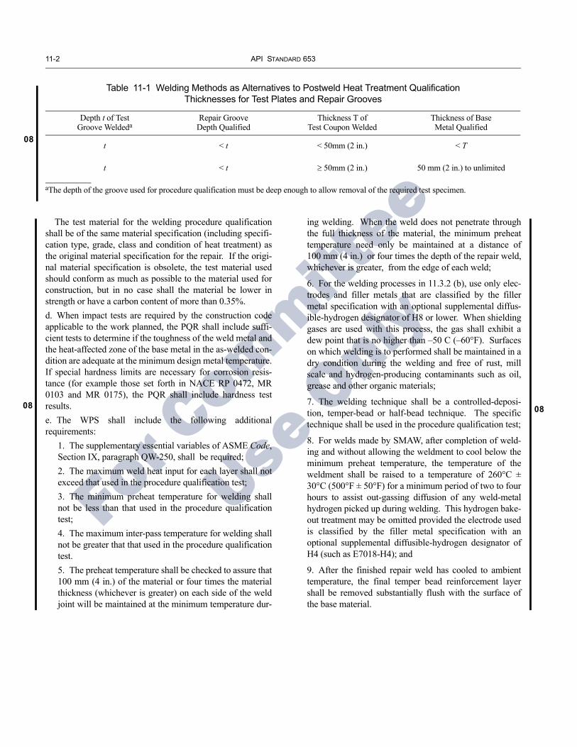
08
11-2 API STANDARD 653
08 08
For C
ommittee
Use O
nly
Table 11-1 Welding Methods as Alternatives to Postweld Heat Treatment Qualification Thicknesses for Test Plates and Repair Grooves
Depth t of Test Groove Weldeda
Repair Groove Depth Qualified
Thickness T of Test Coupon Welded
Thickness of Base Metal Qualified
t < t < 50mm (2 in.) < T
t < t ≥ 50mm (2 in.) 50 mm (2 in.) to unlimited
aThe depth of the groove used for procedure qualification must be deep enough to allow removal of the required test specimen.
The test material for the welding procedure qualification shall be of the same material specification (including specifi-cation type, grade, class and condition of heat treatment) as the original material specification for the repair. If the origi-nal material specification is obsolete, the test material used should conform as much as possible to the material used for construction, but in no case shall the material be lower in strength or have a carbon content of more than 0.35%.d. When impact tests are required by the construction code applicable to the work planned, the PQR shall include suffi-cient tests to determine if the toughness of the weld metal and the heat-affected zone of the base metal in the as-welded con-dition are adequate at the minimum design metal temperature. If special hardness limits are necessary for corrosion resis-tance (for example those set forth in NACE RP 0472, MR 0103 and MR 0175), the PQR shall include hardness test results. e. The WPS shall include the following additional requirements:
1. The supplementary essential variables of ASME Code, Section IX, paragraph QW-250, shall be required;2. The maximum weld heat input for each layer shall not exceed that used in the procedure qualification test;3. The minimum preheat temperature for welding shall not be less than that used in the procedure qualification test;4. The maximum inter-pass temperature for welding shall not be greater that that used in the procedure qualification test.5. The preheat temperature shall be checked to assure that 100 mm (4 in.) of the material or four times the material thickness (whichever is greater) on each side of the weld joint will be maintained at the minimum temperature dur-
ing welding. When the weld does not penetrate through the full thickness of the material, the minimum preheat temperature need only be maintained at a distance of 100 mm (4 in.) or four times the depth of the repair weld, whichever is greater, from the edge of each weld;
6. For the welding processes in 11.3.2 (b), use only elec-trodes and filler metals that are classified by the filler metal specification with an optional supplemental diffus-ible-hydrogen designator of H8 or lower. When shielding gases are used with this process, the gas shall exhibit a dew point that is no higher than –50 C (–60°F). Surfaces on which welding is to performed shall be maintained in a dry condition during the welding and free of rust, mill scale and hydrogen-producing contaminants such as oil, grease and other organic materials;
7. The welding technique shall be a controlled-deposi-tion, temper-bead or half-bead technique. The specific technique shall be used in the procedure qualification test;
8. For welds made by SMAW, after completion of weld-ing and without allowing the weldment to cool below the minimum preheat temperature, the temperature of the weldment shall be raised to a temperature of 260°C ± 30°C (500°F ± 50°F) for a minimum period of two to four hours to assist out-gassing diffusion of any weld-metal hydrogen picked up during welding. This hydrogen bake-out treatment may be omitted provided the electrode used is classified by the filler metal specification with an optional supplemental diffusible-hydrogen designator of H4 (such as E7018-H4); and
9. After the finished repair weld has cooled to ambient temperature, the final temper bead reinforcement layer shall be removed substantially flush with the surface of the base material.

01
03
03
05
03
03
01
03
03
For C
ommittee
Use O
nly
SECTION 12—EXAMINATION AND TESTING
12.1 NONDESTRUCTIVE EXAMINATIONS
12.1.1 General
12.1.1.1 Nondestructive examinations shall be performed in accordance with API Std 650 and any supplemental requirements given herein.
12.1.1.2 Personnel performing nondestructive examina-tions shall be qualified in accordance with API Std 650 and any supplemental requirements given herein.
12.1.1.3 Acceptance criteria shall be in accordance with API Std 650 and any supplemental requirements given herein.
12.1.1.4 Each newly deposited weld or any cavity result-ing from gouging or grinding operations shall be visually examined over its full length. Additional NDE of these welds may be required as described in the following relevant sec-tions.
12.1.1.5 Appendix G may be used to provide additional guidance in qualifying personnel and procedures when magnetic flux leakage (MFL) tools are used to examine tank bottoms. Owner/operators should determine specific requirements to meet their tank bottom integrity needs.
12.1.2 Shell Penetrations
12.1.2.1 Ultrasonic examination of shell plate for lamina-tions shall be made in the immediate area affected when:
a. Adding a reinforcing plate to an existing unreinforced penetration.b. Adding a hot tap connection.
12.1.2.2 Cavities resulting from gouging or grinding oper-ations to remove attachment welds of existing reinforcing plates shall be examined by magnetic particle or liquid pene-trant methods.
12.1.2.3 Completed welds attaching nozzle neck to shell, and reinforcing plate to shell and to nozzle neck, shall be examined by the magnetic particle or liquid penetrant meth-ods. Consider additional examination (e.g., fluorescent mag-netic particle examination and/or ultrasonic examination) for hot tap connections to shell plates of unknown toughness having a maximum thickness more than 1/2 in. or to shell plates of unknown toughness, as defined in Section 3.
12.1.2.4 Completed welds of stress-relieved assemblies shall be examined by the magnetic particle or liquid penetrant methods after stress relief, but before hydrostatic testing.
12.1.3 Repaired Weld Flaws
12.1.3.1 Cavities resulting from gouging or grinding oper-ations to remove weld defects shall be examined by the mag-netic particle or liquid penetrant methods.
12.1.3.2 Completed repairs of butt-welds shall be examined over their full length by radiographic or ultrasonic methods.
12.1.3.3 Completed repairs of fillet welds shall be exam-ined over their full length by the appropriate nondestructive examination method listed herein.
12.1.4 Temporary and Permanent Attachments to Shell Plates
12.1.4.1 The welds of permanent attachments (not includ-ing shell-to-bottom welds) and, areas where temporary attachments are removed and the remaining weld projections have been removed, shall be examined visually.
12.1.4.2 Completed welds of new permanent attachments (not including shell-to-bottom welds) and areas where tempo-rary attachments have been removed (API Std 650 tank shell materials of Groups IV, IVA, V, or VI), shall be examined by either the magnetic particle method (or, at the option of the purchaser, by the liquid penetrant method).
12.1.5 Shell Plate to Shell Plate Welds
12.1.5.1 New welds attaching existing shell plate to exist-ing or new shell plate shall be examined by radiographic methods (see 12.2). In addition, for plate thicknesses greater than 1 in., the back-gouged surface of the root pass and final pass (each side) shall be examined for its complete length by magnetic particle or liquid penetrant methods.
12.1.5.2 New welds joining new shell plate material to new shell plate material (partial or full shell course replace-ment or addition) need only be examined radiographically in accordance with API Std 650.
12.1.6 Shell-To-Bottom Weld
12.1.6.1 New welding on the shell-to-bottom joint shall be inspected for its entire length by using a right-angle vacuum box and a solution film, or by applying light diesel oil. Addi-tionally, the first weld pass shall be inspected by applying light diesel oil to the side opposite the first weld pass made. The oil shall be allowed to stand at least 4 hours (preferably overnight) and then the weld inspected for wicking action. The oil shall be removed before the weld is completed.
12.1.6.2 As an alternative to 12.1.6.1, the initial weld passes, inside and outside of the shell, shall have all slag and non-metals removed from the surface of the welds and exam-
12-1

12-2 API STANDARD 653
01
01
08
01
08
03
03
08
03
08
01
08
For C
ommittee
Use O
nly
ined visually. Additionally, after completion of the inside andoutside fillet or partial penetration welds, the welds shall betested by pressurizing the volume between the inside and out-side welds with air pressure to 15 psig and applying a solu-tion film to both welds. To assure that the air pressure reachesall parts of the welds, a sealed blockage in the annular pas-sage between the inside and outside welds must be providedby welding at one or more points. Additionally, a small pipecoupling communicating with the volume between the weldsmust be welded on each side of and adjacent to the blockages.The air supply must be connected at one end and a pressuregauge connected to a coupling on the other end of the seg-ment under test.
12.1.6.3 The existing weld at the shell-to-bottom joint shallbe examined by visual, as well as by magnetic particle or liq-uid penetrant methods, for the full length under a welded-onpatch plate. An additional 6 in. of the shell-to-bottom joint oneach side of the welded-on patch plate shall be examined sim-ilarly before placement of the repair plate to assure weldintegrity and to confirm the absence of weld cracks.
12.1.7 Bottoms
12.1.7.1 Upon completion of welding on a tank bottom,the plates and the entire length of new welds for tank bottomplates shall be examined visually for any potential defects andleaks. Particular attention shall apply to areas such as sumps,dents, gouges, three-plate laps, bottom plate breakdowns, arcstrikes, temporary attachment removal areas, and weldinglead arc burns. Visual examination acceptance and repair cri-teria are specified in API Std 650, 8.5. In addition, all newwelds, including the weld attaching a patch plate to the bot-tom, the areas of bottom plate restored by welding, and therestoration of welds found with defects during an internalinspection shall be inspected by one of the methods specifiedin API Std 650, 7.3.3. Leaking areas shall be repaired bygrinding and rewelding as required, and the repaired areashall be retested.
12.1.7.2 In addition to the requirements in 12.1.7.1, theroot and final pass of a welded-on patch plate weld in the crit-ical zone (see 3.12 for definition) shall be visually examinedand examined by either magnetic particle or liquid penetrantmethod over its full length.
12.1.7.3 In addition to the requirements in 12.1.7.1, areasof bottom plate repaired by welding shall be examined by themagnetic particle method or the liquid penetrant method. Inaddition, the repaired area shall also be tested using a vacuumbox and solution or a tracer gas and detector.
12.1.8 Shell Plate
12.1.8.1 Shell Plate Repairs by Weld Metal Deposit
Areas of shell plate to be repaired by welding shall beexamined visually. In addition, shell plate areas repaired bywelding shall be examined by the magnetic particle method(or the liquid penetrant method).
12.1.8.2 Shell Plate Repairs by Lap-Welded Patches
The attachment welds of new lap-welded shell patchesshall be visually examined, and shall be examined by eitherthe magnetic particle or liquid penetrant methods.
12.1.9 Fixed Roofs
Newly welded roof joints and repairs shall be examined inaccordance with API Std 650, 7.3.2.2 and 7.3.7.
12.1.10 Floating Roofs
12.1.10.1 Repair Work to Steel Floating Roofs
After repair work is complete: a. Perform a visual examination from the top and bottomside of the floating roof.b. Perform an air leak, vacuum box, penetrating oil, tracer gas,or other applicable non destructive test of the repaired welds.(Refer to Appendix F—NDE Requirements Summary).
As an alternative to (b), conduct a flotation test of therepaired roof.
Examination and acceptance criteria for NDT shall be inaccordance with 12.1.
12.2 RADIOGRAPHS
12.2.1 Number and Location of Radiographs
The number and location of radiographs shall be in accor-dance with API Std 650 and the following additional require-ments:
12.2.1.1 For vertical joints:
a. New replacement shell plates to new shell plates, no addi-tional radiographs required, other than those required by APIStd 650 for new construction.b. New replacement shell plates to existing shell plates, oneadditional radiograph shall be taken in each joint.c. Repaired joints in existing shell plates shall have one addi-tional radiograph taken in each joint.

TANK INSPECTION, REPAIR, ALTERATION, AND RECONSTRUCTION 12-3
01
01
03
08
05
05
08
05
08
For C
ommittee
Use O
nly
12.2.1.2 For horizontal joints:
a. New replacement shell plates to new shell plates, no addi-tional radiographs required, other than those required by API Std 650 for new construction.b. New replacement shell plates to existing shell plates, one additional radiograph for each 50 ft of repaired horizontal weld.c. Repaired joints in existing shell plates shall have one addi-tional radiograph taken for each 50 ft of repaired horizontal weld.
12.2.1.3 For intersections of vertical and horizontal joints:
a. New replacement shell plates to new shell plates, no addi-tional radiographs required, other than those required by API Std 650 for new construction.b. New replacement shell plates to existing shell plates, each intersection shall be radiographed.c. All repaired intersections in existing shell plates shall be radiographed.
12.2.1.4 For reconstructed tanks, each butt-welded annu-lar plate joint shall be radiographed in accordance with API Std 650.
12.2.1.5 For reconstructed tanks, radiographic inspection is required for 25 percent of all junctions of new welds over existing seams.
The owner/operator shall, with the consent of the contrac-tor, determine the extent of further inspection and repair that may be required.
Any further inspection or repair of existing welds will be handled by contractual agreement between the owner/opera-tor and tank reconstruction contractor.
12.2.1.6 New and replaced shell plate and door sheet welds shall be radiographed. All junctions between repair and existing welds shall be radiographed. If defects are found, 100% radiography shall be performed on the repaired weld.
12.2.1.6.1 For circular replacement plates, a minimum of one radiograph shall be taken regardless of thickness. When the circular replacement plate is located in a shell plate with thickness exceeding 1 in., the weld shall be fully radio-graphed.
12.2.1.6.2 For square and rectangular replacement plates, at least one radiograph shall be taken in a vertical joint, and at least one in a horizontal joint, and one in each corner. When the square or rectangular replacement plate is located in a shell plate with thickness exceeding 1 in., the vertical joints shall be fully radiographed.
12.2.1.7 The minimum diagnostic length of each radio-graph shall be 6 in.
12.2.1.8 For penetrations installed using insert plates as described in 9.8.6, the completed butt welds between the insert plate and the shell plate shall be fully radiographed.
12.2.2 Acceptance Criteria for Existing Shell Plate to Shell Plate Welds
If the radiograph of an intersection between a new and old weld detects unacceptable welds by the current applicable standard, the existing welds may be evaluated according to the as built standard.
12.2.3 Marking and Identification of Radiographs
12.2.3.1 Each film shall show an identification of the welder(s) making the weld. A weld map showing location of welds, weld number, radiograph number, welder identifica-tion, and grading of each weld is an acceptable alternative to this requirement.
12.2.3.2 Radiographs and radiograph records of all repaired welds shall be marked with the letter “R”.
12.3 HYDROSTATIC TESTING
12.3.1 When Hydrostatic Testing Is Required
A full hydrostatic test, held for 24 hours, shall be per-formed on:
a. A reconstructed tank.b. Any tank that has undergone major repairs or major alter-ations (see 3.20) unless exempted by 12.3.2 for the applicable combination of materials, design, and construction features.c. A tank where an engineering evaluation indicates the need for the hydrostatic test due to an increase in the severity of service. Examples of increased service severity are an increase in operating pressure (such as storing a product with a higher specific gravity), lowering the service temperature (see Figure 5-2), and using tanks that have been damaged.
[Text Deleted]
12.3.2 When Hydrostatic Teting is Not Required
12.3.2.1 General
A full hydrostatic test of the tank is not required for major repairs and major alterations if 12.3.2.2 is satisfied plus either of the following:
a. Appropriate parts of 12.3.2.3 through 12.3.2.6, or alternatively,b. Fitness-for-service evaluation per 12.3.2.7.

12-4 API STANDARD 653
08
08
08
08
08
03
08
08
For C
ommittee
Use O
nly
12.3.2.2 Review / Approval / Authorization Requirements
Items a and b below must be satisfied: a. The repair has been reviewed and approved by an engineer experienced in storage tank design in accordance with API Std 650. The engineer must concur in writing with taking the hydrostatic testing exemption.b. The tank owner/operator has authorized the exemption in writing.
12.3.2.3 Shell Repair
12.3.2.3.1 For welds to existing metal, develop welding procedure qualifications based on existing material chemis-try, including strength requirements. Welding procedures shall be qualified with existing or similar materials, and shall include impact testing. Impact testing requirements shall fol-low appropriate portions of API Std 650, 9.2.2 and shall be specified in the repair procedure.
12.3.2.3.2 New materials used for the repair shall meet the current edition of API Std 650 requirements.
12.3.2.3.3 Existing tank materials in the repair area shall meet at least one of the following requirements:
a. API Std 650 requirements (Seventh Edition or later).b. Fall within the “safe for use” area on Figure 5-2.c. Stress in the repair area shall not exceed 7000 lbf/in.2. This limiting stress shall be calculated as follows:
S 2.6 H D Gt
-------------------------=
where
S = shell stress in lbf/in.2,
H = tank fill height above the bottom of repair or alteration in ft,
t = shell thickness at area of interest in in.,
D = tank mean diameter in ft,
G = specific gravity of product.
12.3.2.3.4 New vertical and horizontal shell butt-welds shall have complete penetration and fusion.
12.3.2.3.5 The root pass and final pass examination shall be in accordance with 12.1.5. In addition, the finished weld shall be fully radiographed.
12.3.2.3.6 Shell welds for the reinforcing plate-to-nozzle neck and nozzle neck-to-shell joints shall have complete pen-etration and fusion. The root pass of the nozzle attachment weld shall be back-gouged and examined by magnetic parti-
cle or liquid penetrant methods. The completed weld shall be examined by magnetic particle or liquid penetrant methods and by the ultrasonic method. Examination and acceptance criteria for nondestructive examinations shall be in accor-dance with 12.1.
12.3.2.3.7 See 12.3.2.5 for shell-to-bottom weld restric-tions.
12.3.2.3.8 Door sheets shall comply with the requirements of this standard for shell plate installation, except they shall not extend to or intersect the bottom-to-shell joint.
12.3.2.4 Bottom Repair Within the Critical Zone
12.3.2.4.1 Repairs to the annular ring or bottom plates, within the critical zone (see 3.12) shall comply with the fol-lowing:
a. Meet the requirements of 12.3.2.3.1 through 12.3.2.3.3.b. Be examined visually prior to welding, and examined after the root pass and the final pass by the magnetic particle or liquid penetrant methods. Annular plate butt-welds shall also be examined by ultrasonic methods after the final pass. Examination and acceptance criteria for nondestructive examinations shall be in accordance with 12.1.
12.3.2.5 Shell-To-Bottom Weld Repair
12.3.2.5.1 Repair of the weld attaching the shell to the annular ring or the shell to the bottom plate shall meet one of the following requirements:
a. A portion of the weld (of any length) may be removed and replaced as long as the replaced weld meets the size require-ments of API Std 650, 5.1.5.7, and the portion replaced does not represent more than 50 percent of the required weld cross-sectional area.b. The weld on one side of the shell may be completely removed and replaced for a length not exceeding 12 in. Shell-to-bottom weld repairs replacing more than 50 per-cent of the required weld cross-sectional area shall not be closer than 12 in. to each other, including repairs on the opposite side of the shell.
12.3.2.5.2 Repairs shall be examined prior to welding, after the root pass, and after the final pass by visual, as well as magnetic particle or liquid penetrant methods. Examination and acceptance criteria for nondestructive examinations shall be in accordance with 12.1.
[Text moved to 12.3.3.3.]
12.3.2.6 Minor Shell Jacking
12.3.2.6.1 Tank shell and critical zone materials shall meet one of the requirements of 12.3.2.3.3.

TANK INSPECTION, REPAIR, ALTERATION, AND RECONSTRUCTION 12-5
05
05
08
08
For C
ommittee
Use O
nly
12.3.2.6.2 The engineer shall consider all pertinent vari-ables when exempting a minor shell jacking repair from hydrostatic testing, including but not limited to: the magni-tude of jacking required; material; toughness; quality control; inspection before and after repair; material temperature; future foundation stability; and jacking techniques (including controls and measurement). Careful consideration shall be given to potential stresses and damage that may result from jacking.
12.3.2.7 Fitness-For-Service Evaluation
The owner/operator may utilize a fitness-for-service or other appropriate evaluation methodology based on estab-lished principles and practices to exempt a repair from hydro-static testing. The procedures and acceptance criteria for conducting an alternative analysis are not included in this standard. This evaluation shall be performed by an engineer experienced in storage tank design and the evaluation meth-odologies used.
12.3.3 Other Cases Not Requiring Hydrostatic Testing
12.3.3.1 General
For clarity, the situations of 12.3.3.2 and 12.3.3.3 do not in themselves require a hydrostatic test because they are not major repairs or major alterations.
12.3.3.2 Repair or Alteration made to a Floating Roof
No hydrotest is required.
12.3.3.3 Bottom Repair or Replacement Outside the Critical Zone
Portions of new bottoms (any or all rectangular plates or large segments of plates) in tanks may be replaced without a hydrotest when the subgrade under the new plates is found to be in a condition acceptable to the authorized inspector or is restored to such condition and either of the following condi-tions is met:
1. For tanks with annular rings, the annular ring and the area of support under the annular ring (concrete founda-tion or grade material) remains intact.
2. For tanks without annular rings, the bottom repair or replacement does not result in welding on the remaining bottom within the critical zone and the shell and bottom support in the critical zone remains intact. See 3.12 for a definition of the critical zone.
12.4 LEAK TESTS
New or altered reinforcing plates of shell penetrations shall be given an air leak test in accordance with API Std 650.
12.5 MEASURED SETTLEMENT DURING HYDROSTATIC TESTING
12.5.1 Initial Survey
12.5.1.1 Where settlement is anticipated, a tank receiv-ing a hydrostatic test shall have the foundation checked for settlement.
12.5.1.2 Tank settlement shall initially be surveyed with the tank empty using the number of bottom plate projection elevation measurement points, N, uniformly distributed around the circumference, as indicated by the following for-mula:
N D10------=
where
N = minimum required number of settlement mea-surement points, but no less than eight. All frac-tional values shall be rounded to the next higher whole number. The maximum spacing between settlement measurement points shall be 32 ft.
D = tank diameter, in ft.
12.5.1.3 Tank settlement measurements in 12.5.1.2 shall be evaluated for acceptance in accordance with Appendix B.
12.5.2 Survey During Hydrostatic Testing
Settlement shall be measured during filling and when water reaches 100 percent of test level. Excessive settlement in accordance with Appendix B shall be cause to stop the test for foundation investigation and/or repair.

For C
ommittee
Use O
nly

05
05
For C
ommittee
Use O
nly
SECTION 13—MARKING AND RECORDKEEPING
13.1 NAMEPLATES
13.1.1 Tanks reconstructed in accordance with this stan-dard shall be identified by a corrosion-resistant metal name-plate similar to that shown in Figure 13-1. Letters and numerals not less than 5/32 in. high shall be embossed, engraved, or stamped in the plate to indicate information as follows:
a. Reconstructed to API 653.b. Edition and revision number.c. Year reconstruction was completed.d. If known, the as-built standard and the year of original construction.e. Nominal diameter.f. Nominal shell height.g. Design specific gravity.h. Maximum permissible operating liquid level.i. The name of the reconstruction contractor and the assigned serial number or contract number.j. The owner/operator’s tank number.k. Shell material for each shell course.l. Maximum operating temperature.m. Allowable stress used in calculations of each shell course.
13.1.2 The new nameplate shall be attached to the tank shell adjacent to the existing nameplate, if any. An existing nameplate shall be left attached to the tank. Nameplates shall be attached as specified in API Std 650.
13.2 RECORDKEEPING
When a tank is evaluated, repaired, altered, or recon-structed in accordance with this standard, the following infor-mation, as applicable, shall be made a part of the owner/operator’s records for the tank (see 6.8).
13.2.1 Calculations for:
a. Component evaluation for integrity, including brittle frac-ture considerations (Section 5).b. Rerating (including liquid level).c. Repair and alteration considerations.
13.2.2 Construction and repair drawings.
13.2.3 Additional support data including, but not limited to, information pertaining to:
a. Inspections (including thicknesses).b. Material test reports/certifications.c. Tests.d. Radiographs (radiographs shall be retained for at least one year).e. Brittle fracture considerations.f. Original tank construction data (date, as-built standard, etc.).g. Location and identification (owner/operator’s number, serial number).h. Description of the tank (diameter, height, service).i. Design conditions (liquid level, specific gravity, allowable stress, unusual design loadings, etc.).j. Shell material and thickness by course.k. Tank perimeter elevations.l. Construction completion record.m. Basis for hydrostatic test exemption.
13.3 CERTIFICATION
Tanks reconstructed in accordance with this standard shall require documentation of such reconstruction, and certifica-tion that the design, reconstruction, inspection, and testing was performed in compliance with this standard. The certifi-cation shall contain information as shown in Figure 13-2 for design and/or reconstruction as applicable.
13-1

13-2 API STANDARD 653
For C
ommittee
Use O
nlyFigure 13-1—Nameplate
RECONSTRUCTED TO API 653 EDITION
Original Standard
Tank No.
Tank Diam. Height
Specific Gravity
Design Pressure
Orig. Const. Date
Year Reconstructed
Liquid Level Max.
Capacity
Max. Operating Temp.
Date Completed
Serial No.
ShellCourse
AllowableStress Material
Reconstructed by:

TANK INSPECTION, REPAIR, ALTERATION, AND RECONSTRUCTION 13-3
For C
ommittee
Use O
nly
Figure 13-2—Certification Forms
CERTIFICATION FOR TANKRECONSTRUCTED TO API 653
We hereby certify that the tank reconstructed at ___________________________________________ and described as follows:Location
Serial No. Owner's No. Height Capacity Floating or Fixed Roof
Reconstruction Organization
Authorized Representative
Date
Reconstruction Organization
Authorized Representative
Date
was reconstructed, inspected, and tested in accordance with all applicable requirements of API Standard 653,
________________ Edition, ________________ Revision, Dated ________________ (including all material supplied by the
reconstruction organization).
CERTIFICATION FOR TANKDESIGNED TO API 653
We hereby certify that the design evaluation of the tank reconstructed at _______________________________________________ and described as follows: Location
Serial No. Owner's No. Height Capacity Floating or Fixed Roof
was performed by the undersigned organization in accordance with all design requirements of API Standard 653,
________________ Edition, ________________ Revision, Dated ________________.

For C
ommittee
Use O
nly

08
01
03
08
For C
ommittee
Use O
nly
APPENDIX A—BACKGROUND ON PAST EDITIONS OF API WELDED STORAGE TANK STANDARDS
API published a specification for welded steel storage tanks in 1936 entitled API Standard 12C, API Specification for Welded Oil Storage Tanks. Fifteen editions and seven supplements to Standard 12C were published between 1936 and 1961. API Std 12C was replaced by API Std 650, Welded Steel Tanks for Oil Storage; eleven editions and eighteen supplements, revisions or addenda to API Standard 650 have been issued. The current edition of API Std 650 is the Eleventh Edition, published in June 2007.
The table below provides a list of editions, supplements, and revisions to API Std 12C and API Std 650.
Table A-1—Editions of API Standard 650 and Its Precursor, Standard 12C
Standard 12C, API Specification for Welded Oil Storage Tanks Standard 650, Welded Steel Tanks for Oil Storage
Edition Date Edition Date
First July 1936 First December 1961
Second October 1937 Supplement 1963
Supplement 1 April 1938 Second April 1964
Supplement 2 September 1938 Third July 1966
Supplement 3 April 1939 Supplement 1 December 1967
Third April 1940 Fourth June 1970
Fourth March 1941 Supplement 1 April 1971
Fifth May 1942 Fifth July 1973
Sixth August 1944 Supplement 1 October 1973
Seventh August 1946 Supplement 2 April 1974
Supplement 1 September 1947 Supplement 3 March 1975
Eighth September 1948 Sixth April 1977
Supplement 1 December 1949 Revision 1 May 1978
Ninth October 1950 Revision 2 December 1978
Tenth September 1951 Revision 3 October 1979
Eleventh September 1952 Seventh November 1980
Supplement 1 September 1953 Revision 1 February 1984
Twelfth October 1954 Eighth November 1988
Thirteenth September 1955 Ninth July 1993
Supplement 1 October 1956 Addendum 1 December 1994
Fourteenth October 1957 Addendum 2 December 1995
Fifteenth 1958 Addendum 3 December 1996
Addendum 4 December 1997
Tenth November 1998
Addendum 1 March 2000
Addendum 2 November 2001
Addendum 3 August 2003
Addendum 4 December 2005
Eleventh June 2007
Note: Ordering information for past editions of API Std 12C and API Std 650 is available by calling Global Engineering Documents at 1-800-854-7179 (www.global.ihs.com).
A-1

For C
ommittee
Use O
nly

05
0503
For C
ommittee
Use O
nly
APPENDIX B—EVALUATION OF TANK BOTTOM SETTLEMENT
B.1 IntroductionB.1.1 In determining the effects of soil settlement on stor-age tanks, it is common practice to monitor settlement of the tank bottom. In most cases, such a monitoring program is initiated during the construction and continued during hydrostatic testing and operations. During operations, set-tlement measurements should be taken at a planned fre-quency, based on an assessment of soil settlement predictions. For existing tanks that do not have initial settle-ment data, a program of settlement monitoring should be based on prior service history.
B.1.2 If at any time settlement is deemed excessive, the tank should be emptied and re-leveled. Re-leveling of a siz-able tank is expensive and rather difficult to achieve. Thus, a decision to re-level a tank is a crucial one, and relies very much on the proper interpretation and evaluation of the moni-tored settlement data.
B.1.3 Approaches used to correct tank shell and bottom settlement include techniques such as localized repairs of the bottom plates, partial re-leveling of the tank periphery, and major re-leveling of the entire tank bottom. Major re-levelingof the tank, involving total lifting of the tank shell and bottom at one time, can introduce highly localized stresses in the structure and impair its integrity. Therefore, when choosing techniques for correcting settlement problems, an alternative to total lifting of the tank shell and bottom should be consid-ered as a first choice. If it is decided to lift the entire tank shell and bottom at one time, it should be done by personnel with demonstrated experience in this technique.
B.2 Types of SettlementB.2.1 ELEVATION MEASUREMENTS
The principal types of tank settlement consist of settle-ments that relate to the tank shell and bottom plate. These set-tlements can be recorded by taking elevation measurements around the tank circumference and across the tank diameter. Figures B-1 and B-2 show recommended locations on a tank shell and bottom plate for settlement measurements. Data obtained from such measurements should be used to evaluate the tank structure. Additional settlement readings may be required to define local depressions.
Figure B-1—Measurements of Shell Settlement (External)
011
10
9 3
1
7
8
65
4
2
Tank shell
Maximum spacing of 32 ft around circumference. There must be at least 4 equally spaced diametrical measurement lines.
Notes:1. There must be at least eight settlement points. The maximum spacing of the settlement points is 32 ft around the circumference.2. Points shall be equally spaced around the tank shell. See 12.5.1.2 formethod of determining the number of measurement points.
B.2.2 SHELL SETTLEMENT EVALUATION
Settlement of a tank is the result of either one, or a combi-nation of the following three settlement components.
B.2.2.1 Uniform settlement. This component often can be predicted in advance, with sufficient accuracy from soil tests.
It may vary in magnitude, depending on the soil characteris-tics. Uniform settlement of a tank does not induce stresses in the tank structure. However, piping, tank nozzles, and attach-ments must be given adequate consideration to prevent prob-lems caused by such settlement.
B.2.2.2 Rigid body tilting of a tank (planar tilt). This com-ponent rotates the tank in a tilted plane. The tilt will cause an increase in the liquid level and, therefore, an increase in the hoop stress in the tank shell. Also, excessive tilting can cause binding of peripheral seals in a floating roof and inhibit roof travel. This type of settlement could affect tank nozzles that have piping attached to them. Figure B-3 shows that the set-tled location of the tank shell, after rigid body tilt, can be rep-resented by either a cosine or sine wave with respect to its original position in a horizontal plane.
B.2.2.3 Out-of-plane settlement (differential settlement). Due to the fact that a tank is a rather flexible structure, chances are great that the tank shell will settle in a nonplanar configuration, inducing additional stresses in the tank shell. The out-of-plane settlements at the bottom edge lead to a lack of circularity at the top of the tank, and in the case of a float-
B-1

B-2 API STANDARD 653
05
03
For C
ommittee
Use O
nlyFigure B-2—Measurements of Bottom Settlement
(Internal) Tank Out-of-Service
Maximum spacingof 32 ft aroundcircumference.There must be atleast 4 equallyspaced diametricalmeasurement lines.
Tank shell
Maximum spacingof 10 ft acrossdiameter.
05 1
24
3 3
42
1 50
Note: See 12.5.1.2 for method of determining the number of measurement points.
ing roof tank, the extent of the induced ovality may impede the proper functioning of the floating roof in such a way that re-leveling is required. Also, such settlements may cause flat spots to develop in the tank shell. This type of settlement could affect tank nozzles that have piping attached to them.
B.2.2.4 While uniform settlement and rigid body tilt of a tank may cause problems as described above, the out-of-plane settlement is the important component to determine and evaluate in order to ensure the structural integrity of the shell and bottom. Based on this principle, a common approach is to determine the magnitudes of the uniform and rigid body tilt component (if any) for each data point on the tank periphery. Once this is carried out, the plane of rigid tilt is then impor-tant as a datum from which to measure the magnitudes of the out-of-plane settlements.
A graphical representation illustrating the effect of tank shell settlement components is shown in Figure B-3. The construction of this settlement plot has been developed in accordance with the following:
a. The actual edge settlement (in most cases an irregular curve) is plotted using points around the tank circumference as the abscissa.b. The vertical distance between the abscissa and the lowest point on this curve (point 22) is the minimum settlement, and
it is called the uniform settlement component. A line through this point, parallel to the abscissa, provides a new base or datum line for settlement measurements called adjusted settlements.c. The plane of rigid tilt settlement is represented by the opti-mum cosine curve between the maximum and minimum values of the actual edge settlements. Several methods exist for determining the optimum cosine curve. The least accurate method is by free hand drawing techniques, a kind of trial and error procedure to fit the best cosine curve through the data. A better method is to use the mathematical and graphical capabilities of a computer.d. The vertical distances between the irregular curve and the cosine curve represent the magnitudes of the out-of-plane set-tlements (Ui at data point i).e. The most commonly used and accepted method is to use a computer to solve for constants a, b, and c, to find the opti-mum cosine curve of the form:
Elevpred = a + b × cos (θ + c)
Where Elevpred is the elevation predicted by the cosine curve at angle theta. A typical starting point for a computer best-fit cosine curve is a least-squares fit where a, b, and c are chosen to minimize the sum of the square of the differences between measured and predicted elevations. The optimum cosine curve is only considered valid (i.e., accurately fits the measured data) if the value R2 is greater than or equal to 0.9.
R2 Syy SSE–( )Syy
---------------------------=
where
Syy = sum of the squares of the differences between average measured elevation and the measured elevations,
SSE = sum of the square of the differences between the measured and predicted elevations.
Obtaining a statistically valid cosine curve may require taking more measurements than minimums shown in Figure B-1. In many cases, the out-of-plane settlement may be con-centrated in one or more areas and the least-squares fit under predicts the local out-of-plane settlement and is not conser-vative. In these cases, R2 will typically be less than 0.9. Appropriately selecting a, b, and c will result in very little difference between predicted and measured elevation at all but one or two measurements points, and R2 will be greater than 0.9. One method of selecting a, b, and c in these cases is to ignore one or two points that do not appear to fit the ini-tially calculated cosine curve, and recalculate the optimum cosine curve. The remaining points will show a good esti-

TANK INSPECTION, REPAIR, ALTERATION, AND RECONSTRUCTION B-3
For C
ommittee
Use O
nly
Figure B-3—Graphical Representation of Tank Shell Settlement
U10
U11
U12
U13
Max. settlement at(Pt. 11)
Min.settlement
(Pt. 22)
Plane of rigid tiltrepresented by optimum cosine curve
Actual edgesettlement
Uniform or minimum settlement
Dat
um li
ne fo
r adj
uste
d se
ttlem
ent
Dat
um li
ne fo
r net
set
tlem
ent
N (23) data points, equally (L) spaced apart.
Tank circumference envelope ( D)
1 3 5 72 4 6
98
1110
1312
1514
1716
1918
2120
2322 1
Out-of-plane deflection for point “i” isSi = Ui 1/2 Ui + 1/2 Ui +1), for exampleS11 = U11
1/2U10 + 1/2U12)
Ui = out-of-plane settlement of point “i”,(+) when above cos. curve;
U11 = (+)U13
Note: See 12.5.1.2 for definition of “N.”
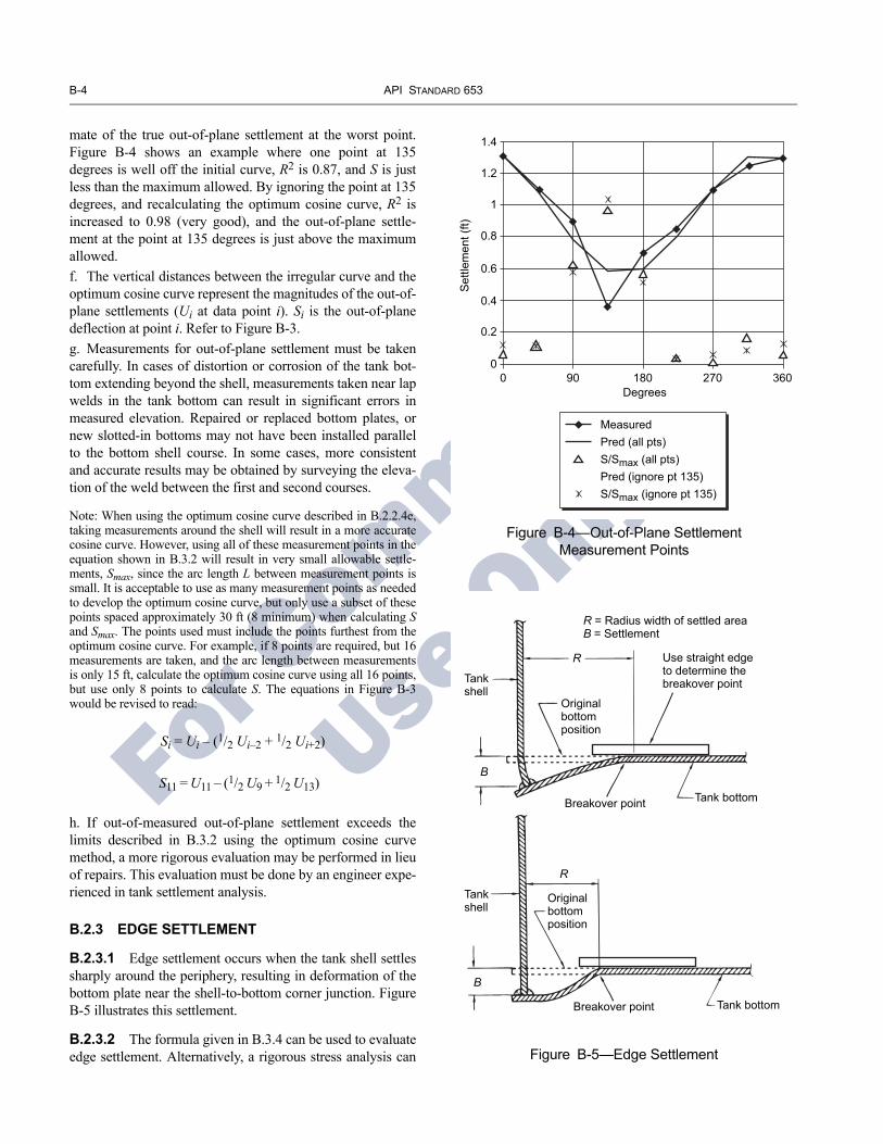
B-4 API STANDARD 653
For C
ommittee
Use O
nly
mate of the true out-of-plane settlement at the worst point. Figure B-4 shows an example where one point at 135 degrees is well off the initial curve, R2 is 0.87, and S is just less than the maximum allowed. By ignoring the point at 135 degrees, and recalculating the optimum cosine curve, R2 is increased to 0.98 (very good), and the out-of-plane settle-ment at the point at 135 degrees is just above the maximum allowed.f. The vertical distances between the irregular curve and the optimum cosine curve represent the magnitudes of the out-of-plane settlements (Ui at data point i). Si is the out-of-plane deflection at point i. Refer to Figure B-3.g. Measurements for out-of-plane settlement must be taken carefully. In cases of distortion or corrosion of the tank bot-tom extending beyond the shell, measurements taken near lap welds in the tank bottom can result in significant errors in measured elevation. Repaired or replaced bottom plates, or new slotted-in bottoms may not have been installed parallel to the bottom shell course. In some cases, more consistent and accurate results may be obtained by surveying the eleva-tion of the weld between the first and second courses.
Note: When using the optimum cosine curve described in B.2.2.4e, taking measurements around the shell will result in a more accurate cosine curve. However, using all of these measurement points in the equation shown in B.3.2 will result in very small allowable settle-ments, Smax, since the arc length L between measurement points is small. It is acceptable to use as many measurement points as needed to develop the optimum cosine curve, but only use a subset of these points spaced approximately 30 ft (8 minimum) when calculating Sand Smax. The points used must include the points furthest from the optimum cosine curve. For example, if 8 points are required, but 16 measurements are taken, and the arc length between measurements is only 15 ft, calculate the optimum cosine curve using all 16 points, but use only 8 points to calculate S. The equations in Figure B-3 would be revised to read:
Si = Ui – (1/2 Ui–2 + 1/2 Ui+2)
S11 = U11 – (1/2 U9 + 1/2 U13)
Figure B-4—Out-of-Plane Settlement Measurement Points
1.4
1.2
1
0.8
0.6
0.4
0.2
00 90 180 270 360
Set
tlem
ent (
ft)
Degrees
MeasuredPred (all pts)S/Smax (all pts)Pred (ignore pt 135)S/Smax (ignore pt 135)
h. If out-of-measured out-of-plane settlement exceeds the limits described in B.3.2 using the optimum cosine curve method, a more rigorous evaluation may be performed in lieu of repairs. This evaluation must be done by an engineer expe-rienced in tank settlement analysis.
B.2.3 EDGE SETTLEMENT
B.2.3.1 Edge settlement occurs when the tank shell settles sharply around the periphery, resulting in deformation of the bottom plate near the shell-to-bottom corner junction. Figure B-5 illustrates this settlement.
Figure B-5—Edge Settlement
Breakover point
Tankshell
Tankshell
Originalbottomposition
Originalbottomposition
R
R
Tank bottom
Tank bottom
B
B
R = Radius width of settled areaB = Settlement
Use straight edgeto determine thebreakover point
Breakover point
B.2.3.2 The formula given in B.3.4 can be used to evaluate edge settlement. Alternatively, a rigorous stress analysis can

TANK INSPECTION, REPAIR, ALTERATION, AND RECONSTRUCTION B-5
05
05
05
05
For C
ommittee
Use O
nly
be carried out for the deformed profile. Measure the edge set-tlement carefully, taking into account the following:
a. Measurements taken when the bottom is not in contact with the soil or foundation under the tank can overestimate or underestimate edge settlement significantly. If the measured settlement is near the maximum allowable settlement, con-sider repeating the measurement with the bottom forced down to the soil, e.g., standing on it, or take an additional set of measurements in the same area, where the bottom is in firm contact with the soil.b. Locating the breakover point where the settled area begins requires some judgment. Placing a straight edge on the unset-tled bottom as shown in Figure B-5, and observing where the bottom separates from the straight edge will help define the breakover point.
c. If the tank bottom is cone up or cone down, the settlement B, should be measured from a projection of the unsettled bot-tom, not from level. See Figure B-6.
Cone downbottom
Cone upbottom
Shell
Originalbottomposition
Settled bottomposition
Shell
Original bottom
Breakover
Settled bottom
B — Measured from originalbottom position
B — Incorrect!Measured from level line frombreakover point to shell
Figure B-6—Correction for Measured Edge Settlement
B.2.3.3 The measured edge settlement B is defined as shown in Figure B-5. Bew is defined as the allowable edge settlement in an area where there is a bottom lap weld in the settled area that is essentially parallel (± 20 degrees) to the shell. Be is defined as the allowable settlement in an area with no bottom welds, or only butt-welds in the bottom, or lap welds in the bottom that are essentially perpendicular (± 20 degrees) to the shell. Refer to Figure B-4.
B.2.3.4 Section B.3.4 provides methods for evaluation of measured edge settlement B against allowable edge settle-ment Bew and Be. Since Bew is more conservative than Be, the simplest approach is to initially evaluate measured settlement

B-6 API STANDARD 653
For C
ommittee
Use O
nly
B against Bew for all settled areas. If all areas meet this crite-rion, the settlement is acceptable and no further evaluation is necessary. If necessary, different settled areas can be evalu-ated separately against Bew and Be. For areas containing lap welds at an arbitrary angle to the shell, interpolation to find an allowable settlement between Bew and Be based on the angle of the weld to the shell is allowed.
B.2.4 BOTTOM SETTLEMENT NEAR THE TANK SHELL
B.2.4.1 Figure B-7 illustrates bottom settlement near the tank shell.
B.2.4.2 The formula given in B.3.3 can be used to evaluate settlement near the tank shell. Alternatively, a rigorous stress analysis can be carried out for the deformed profile.
B.2.5 LOCALIZED BOTTOM SETTLEMENT REMOTE FROM THE TANK SHELL
B.2.5.1 Localized bottom settlement remote from tank shell are depressions (or bulges) that occur in a random man-ner, remote from the shell (see Figure B-8).
B.2.5.2 Acceptability of these localized settlements is dependent on localized stresses in the bottom plate, design and quality of the lap welds (single-pass or multi-pass), and voids below the bottom plate. The formula given in B.3.3 can be used to evaluate localized settlement remote from the tank shell. These limits are applicable to tank bottoms that have single-pass lap-welded joints.
Figure B-7—Bottom Settlement Near Shell
R RB
B
Tank shell
A A
SECTION A-A
R = Radius of inscribed circle in bulged or depressed areaB = Settlement or depression depth or height of bulge
R
R R
R
R 2R
B.3 Determination of Acceptable Settlement
B.3.1 GENERAL
For existing tanks with history of successful service, it may be possible to accept greater settlement and distortion of the foundation from a true plane than new tank construction stan-dards allow. Each tank must be evaluated based on service conditions, materials of construction, soil characteristics, tank foundation design, and tank service history. The methods dis-cussed in following sections are not mandatory and approxi-mate the maximum permissible settlement. However, experience has shown that if settlements exceed the following requirements, further assessment or repair is required.
B.3.2 SHELL SETTLEMENT
From the measurements described in B.2, determine the maximum out-of-plane deflection. Use the following formula
to calculate the maximum permissible out-of-plane deflection (see note below.)
S L2 Y× 11×( )2 E H×( )[ ]
-----------------------------≤
where
S = deflection, in ft (out of plane distortion),
L = arc length between measurement points, in ft,
Y = yield strength, in lbf/in.2,
E = Young’s modulus, in lbf/in.2,
H = tank height, in ft.
Note: This formula is based on “Criteria for Settlement of Tanks,” W. Allen Marr, M. ASCE, Jose A. Ramos, and T. William Lambe, F. ASCE, Journal of Geotechnical Engineering Division, Proceedings of the American Society of Civil Engineers, Vol. 108, August 1982.

TANK INSPECTION, REPAIR, ALTERATION, AND RECONSTRUCTION B-7
05
05
05
05
05
For Committee
Use O
nly
Figure B-8—Localized Bottom Depressions or Bulges Remote from Shell
Localized depressionsor bulges in tankbottom plate
RR
B
B
Tank shell
A A
R
R
R
R = Radius of inscribed circle in bulged or depressed area
B = Settlement depth or height of bulge
B.3.3 INTERNAL BOTTOM SETTLEMENTS OR BULGES
Measure the bulge or depression. The permissible bulge or depression is given by the following formula (see note below).
BB = 0.37R
where
BB = maximum height of bulge or depth of local depression, in.,
R = radius of inscribed circle in bulged area or local depression, in ft.
Figure B-9 is a graphical representation of this formula.
Note: This formula is based on “Criteria for Settlement of Tanks,” W. Allen Marr, M. ASCE, Jose A. Ramos, and T. William Lambe, F. ASCE, Journal of Geotechnical Engineering Division, Proceedings of the American Society of Civil Engineers, Vol. 108, August 1982.
B.3.4 EDGE SETTLEMENT
B.3.4.1 Maximum allowable settlement Bew is shown in Figure B-10 for settled areas that include bottom lap welds essentially parallel to the shell (± 20 degrees). In settled areas where the measured settlement B exceeds 75 percent of allowed settlement Bew, all shell-to-bottom welds and bottom welds should be inspected visually and with mag-netic particle examination or liquid penetrant examination. All indications should be repaired, or evaluated for risk of brittle fracture, and/or fatigue failure prior to returning the tank to service.
B.3.4.2 For settled areas where measured settlement Bexceeds 75 percent of Bew, any welds within 12 in. of either side of the breakover area (see Figure B-5) should be exam-ined visually. Any suspect areas should be examined with either magnetic particle examination or liquid penetrant examination. All indications should be repaired or evaluated for risk of fatigue prior to returning the tank to service.
B.3.4.3 Maximum allowable settlement Be is shown in Figure B-11 for areas of edge settlement with no welds, butt welds, or lap welds in the bottom that are essentially radial to the shell (± 20 degrees). In settled areas where the measured settlement exceeds 75 percent of the allowed settlement, all shell-to-bottom welds and bottom welds should be inspected visually and with magnetic particle examination or liquid penetrant examination. All indications should be repaired or evaluated for risk of brittle fracture and/or fatigue prior to returning the tank to service.
B.3.4.4 Maximum allowable settlement for areas of edge settlement with a lap weld at an arbitrary angle to the shell may be interpolated from Be and Bew from Figures B-10 and B-11, and the following formula:
Bα = Be – (Be – Bew) x sin α
Where α is the angle of the weld to a tank centerline and Bα is the allowable settlement for an area with a weld at that angle (see Figure B-12).
B.3.4.5 In general, settlement occurs slowly, and for most existing tanks, the majority of settlement is presumed to have occurred in the first few years of service. Significant addi-tional settlement will not be expected after the initial inspec-tions. Therefore, typical practice is to compare the measured edge settlement with the maximum allowable edge settlement Bew and Be, and not include allowance for additional settle-

B-8 API STANDARD 653
For C
ommittee
Use O
nlyFigure B-9—Localized Tank Bottom Settlement Limits for Single Pass Welds
15
14
13
12
11
10
9
8
7
6
5
4
3
2
1
00 5 10 15 20 25 30 35 40 45
Repairs or a rigorous assessmentshould be conducted if the depthof the observed bulge ordepression is above this line
B
RRR RR
BR R R R
Partial ring-type depressionor bulge(at edge only)where R < 2R
Depressionor bulge(anywhere)
B =
Dep
th o
f dep
ress
ion
or b
ulge
at c
ente
r (in
ches
)
R = Radius of inscribed circle in depression or bulge (feet)
ment during subsequent operation. Note that erosion of the pad adjacent to the tank may cause local settlement. In this case the settlement will continue unless the pad is repaired and future erosion prevented. For cases where significant additional settlement is expected, an engineer experienced in tank settlement evaluation should evaluate the settlement expected at the next inspection with the limits in B.3.4. This is analogous to a corrosion allowance for components expected to corrode.
B.3.4.6 The edge settlement limits described in B.2.3.1 through B.2.3.5 were developed for typical 1/4-in. thick tank bottoms with minimal corrosion.
a. Edge settlement limits can be applied with reasonable accuracy to 5/16- and 3/8-in. thick tank bottoms.b. Edge settlement limits can be applied with reasonable accuracy to bottoms with general corrosion, as long as the areas near all welds are thicker than 3/16 in.c. Edge settlement limits can be applied with reasonable accuracy to bottoms with local corrosion, if all locally thin areas in the settled area (closer than “R” to the shell) thinner
than 3/16 in. are smaller than 12 in. in diameter and the thin area does not include a weld.d. Settlement is presumed to be slow, and a small amount of additional settlement is expected to occur prior to the next inspection.
B.3.4.7 Edge settlement increases secondary stress at the bottom-to-shell weld. If weld repairs are made to the bottom-to-shell weld in an area where settlement exceeds 1/2 of Be, these additional stresses should be evaluated by an engineer experienced in tank settlement evaluation before waiving a hydrostatic test per 12.3.
B.4 RepairsB.4.1 If it is determined that settlements have occurred which are beyond the permissible limits established in the previous sections, then consideration should be given to mak-ing repairs or a rigorous stress analysis should be performed to evaluate the deformed profile. Various repair techniques have been discussed above. The judgment on repairs should be tempered with knowledge of tank service history, previous

TANK INSPECTION, REPAIR, ALTERATION, AND RECONSTRUCTION B-9
05
05
5
For C
ommittee
Use O
nly
Figure B-10—Maximum Allowable Edge Settlement for Areas with Bottom Lap Welds Approximately Parallel to the Shell
10.00
9.00
8.00
7.00
6.00
5.00
4.00
3.00
2.00
1.00
0.000 1 2 3 4 5 6
Tanks with larger edge settlements are to be repaired, or have detailed analysis of bottom, and bottom-to-shell junction
Welds in tanks with settlement greater than or equal 75% of Bew,and larger than 2 in., are to be inspected with magnetic particle or liquid penetrant examination
Diameter, ft
Tanks with settlement less than 75% of Bew may be returned to service
160 & Larger
120
100
80
60504030
20
repairs, previous inspections, tank foundation conditions, soil characteristics, the material of construction, and estimates of future settlement. See 9.10 for suggested repair details.
B.4.2 For tanks with edge settlement exceeding the lim-its and assumptions given in B.2.3.1 through B.2.3.7, the tank should be repaired. Any plate exceeding acceptable strains (typically 2 percent – 3 percent) should be replaced. Re-leveling the tank will not remove the plastic strain, so leveling the tank without replacing the strain may not be a sufficient repair. Welds in the area of the high strains should be removed and replaced, or be subjected to a fitness-for-service evaluation by an engineer experi-enced in tank settlement evaluation. The condition leading
to the unacceptable settlement should be corrected. Depending on the severity and location of the settlement, required repairs may include regrading the soil under the tank bottom, and/or repairing the foundation. Jacking and re-leveling the shell may be required to prevent additional settlement damage. Jacking and leveling are usually done in conjunction with, not instead of, replacing damaged plate and welds. In lieu of repairs, a detailed analysis of the settled area may be performed by an engineer experi-enced in tank design and settlement evaluation. The analy-sis should consider primary and secondary stress and the risk of brittle fracture.
0

B-10 API STANDARD 653
05
For C
ommittee
Use O
nly
Figure B-11—Maximum Allowable Edge Settlement for Areas with Bottom Lap Welds Approximately Perpendicular to the Shell
10.00
9.00
8.00
7.00
6.00
5.00
4.00
3.00
2.00
1.00
0.000 1 2 3 4 5 6
Tanks with larger edge settlements are to be repaired, or have detailed analysis of bottom, and bottom-to-shell junction
Welds in tanks with settlement greater than or equal 75% of Bew,and larger than 2", are to be inspected with magnetic particle or liquid penetrant examination
Diameter, ft
Tanks with settlement less than 75% of Bew may be returned to service
160 & Larger
120
100
80
60
50
40
30
20

TANK INSPECTION, REPAIR, ALTERATION, AND RECONSTRUCTION B-11
5
For C
ommittee
Use O
nly
Figure B-12—Edge Settlement with a Lap Weld at an Arbitrary Angle to the Shell
Anglealpha
Settledarea
Tankcenterline
Bottom platelayout
0

For C
ommittee
Use O
nly

F
or Committ
ee
Use O
nlyAPPENDIX C—CHECKLISTS FOR TANK INSPECTION
Appendix C contains sample checklists illustrating tank components and auxiliary items that should be considered for internal and external inspection of tanks. This informa-tion is provided as guidance to the owner/operator for developing an inspection assess-ment schedule for any specific tank installation. The checklist format facilitates the recording of inspection findings.
C-1

For C
ommittee
Use O
nly

TANK INSPECTION, REPAIR, ALTERATION, AND RECONSTRUCTION C-3
05
For Committee
Use O
nly
TANK IN-SERVICE INSPECTION CHECKLIST
Item Completed √ Comments
C.1.1 FOUNDATION
Measure foundation levelness and bottom elevations (see Appendix B for extent of measurements).
C.1.1.1 Concrete Ring
a. Inspect for broken concrete, spalling, and cracks, particularly under backup bars used in welding butt-welded annular rings under the shell.
b. Inspect drain openings in ring, back of waterdraw basins and top surface of ring for indications of bottom leakage.
c. Inspect for cavities under foundation and vegetation against bottom of tank.
d. Check that runoff rainwater from the shell drains away from tank.
e. Check for settlement around perimeter of tank.
C.1.1.2 Asphalt
a. Check for settling of tank into asphalt base which would direct runoff rain water under the tank instead of away from it.
b. Look for areas where leaching of oil has left rock filler exposed, which indicates hydrocarbon leakage.
C.1.1.3 Oiled Dirt or Sand
Check for settlement into the base which would direct runoff rain water under the tank rather than away from it.
C.1.1.4 Rock
Presence of crushed rock under the steel bottom usually results in severe underside corrosion. Make a note to do additional bottom plate examination (ultrasonic, hammer testing, or turning of coupons) when the tank is out of service.
C.1.1.5 Site Drainage
a. Check site for drainage away from the tank and associated piping and manifolds.
b. Check operating condition of the dike drains.
C.1.1.6 Housekeeping
Inspect the area for buildup of trash, vegetation, and other inflammables buildup.
C.1.1.7 Cathodic Protection
Review cathodic protection potential readings.
C.1.2 SHELLS
C.1.2.1 External Visual Inspection
a. Visually inspect for paint failures, pitting, and corrosion.
b. Clean off the bottom angle area and inspect for corrosion and thinning on plate and weld.
c. Inspect the bottom-to-foundation seal, if any.
C.1.2.2 Internal (Floating Roof Tank)
Visually inspect for grooving, corrosion, pitting, and coating failures.
C.1.2.3 Riveted Shell Inspection
a. Inspect external surface for rivet and seam leaks.
b. Locate leaks by sketch or photo (location will be lost when shell is abrasive cleaned for painting).
c. Inspect rivets for corrosion loss and wear.
d. Inspect vertical seams to see if they have been full fillet lap-welded to increase joint efficiency.

C-4 API STANDARD 653
For C
ommittee
Use O
nly
TANK IN-SERVICE INSPECTION CHECKLIST—Continued
Item Completed √ Comments
e. If no record exists of vertical riveted seams, dimension and sketch (or photograph) the rivet pattern: number of rows, rivet size, pitch length, and note whether the joint is butt-riveted or lap-riveted.
C.1.2.4 Wind Girder (Floating Roof Tanks)
a. Inspect wind girder and handrail for corrosion damage (paint failure, pitting, corrosion product buildup), especially where it occurs at tack-welded junction, and for broken welds.
b. Check support welds to shell for pitting, especially on shell plates.
c. Note whether supports have reinforcing pads welded to shell.
C.1.3 SHELL APPURTENANCES
C.1.3.1 Manways and Nozzles
a. Inspect for cracks or signs of leakage on weld joint at nozzles, manways, and rein-forcing plates.
b. Inspect for shell plate dimpling around nozzles, caused by excessive pipe deflection.
c. Inspect for flange leaks and leaks around bolting.
d. Inspect sealing of insulation around manways and nozzles.
e. Check for inadequate manway flange and cover thickness on mixer manways.
C.1.3.2 Tank Piping Manifolds
a. Inspect manifold piping, flanges, and valves for leaks.
b. Inspect fire fighting system components.
c. Check for anchored piping which would be hazardous to the tank shell or bottom connections during earth movement.
d. Check for adequate thermal pressure relief of piping to the tank.
e. Check operation of regulators for tanks with purge gas systems.
f. Check sample connections for leaks and for proper valve operation.
g. Check for damage and test the accuracy of temperature indicators.
h. Check welds on shell-mounted davit clips above valves 6 in. and larger.
C.1.3.3 Autogauge System
a. Inspect autogauge tape guide and lower sheave housing (floating swings) for leaks.
b. Inspect autogauge head for damage.
c. Bump the checker on autogauge head for proper movement of tape.
d. Identify size and construction material of autogauge tape guide (floating roof tanks).
e. Ask operator if tape tends to hang up during tank roof movement (floating roof tanks).
f. Compare actual product level to the reading on the autogauge (maximum variation is 2 in.).
g. On floating roof tanks, when the roof is in the lowest position, check that no more than two ft of tape are exposed at the end of the tape guide.
h. Inspect condition of board and legibility of board-type autogauges.
i. Test freedom of movement of marker and float.
C.1.3.4 Shell-Mounted Sample Station
a. Inspect sample lines for function of valves and plugging of lines, including drain or return-to-tank line.
b. Check circulation pump for leaks and operating problems.
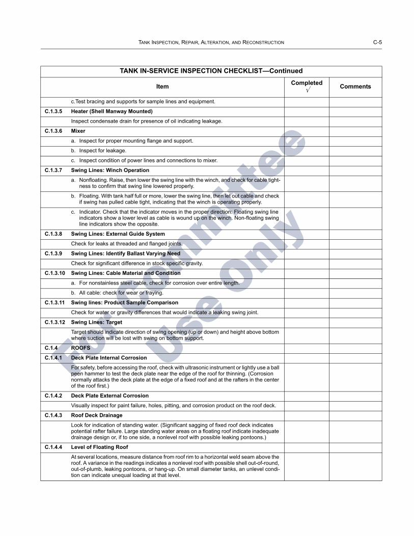
TANK INSPECTION, REPAIR, ALTERATION, AND RECONSTRUCTION C-5
For C
ommittee
Use O
nly
TANK IN-SERVICE INSPECTION CHECKLIST—Continued
Item Completed √ Comments
c.Test bracing and supports for sample lines and equipment.
C.1.3.5 Heater (Shell Manway Mounted)
Inspect condensate drain for presence of oil indicating leakage.
C.1.3.6 Mixer
a. Inspect for proper mounting flange and support.
b. Inspect for leakage.
c. Inspect condition of power lines and connections to mixer.
C.1.3.7 Swing Lines: Winch Operation
a. Nonfloating. Raise, then lower the swing line with the winch, and check for cable tight-ness to confirm that swing line lowered properly.
b. Floating. With tank half full or more, lower the swing line, then let out cable and check if swing has pulled cable tight, indicating that the winch is operating properly.
c. Indicator. Check that the indicator moves in the proper direction: Floating swing line indicators show a lower level as cable is wound up on the winch. Non-floating swing line indicators show the opposite.
C.1.3.8 Swing Lines: External Guide System
Check for leaks at threaded and flanged joints.
C.1.3.9 Swing Lines: Identify Ballast Varying Need
Check for significant difference in stock specific gravity.
C.1.3.10 Swing Lines: Cable Material and Condition
a. For nonstainless steel cable, check for corrosion over entire length.
b. All cable: check for wear or fraying.
C.1.3.11 Swing lines: Product Sample Comparison
Check for water or gravity differences that would indicate a leaking swing joint.
C.1.3.12 Swing Lines: Target
Target should indicate direction of swing opening (up or down) and height above bottom where suction will be lost with swing on bottom support.
C.1.4 ROOFS
C.1.4.1 Deck Plate Internal Corrosion
For safety, before accessing the roof, check with ultrasonic instrument or lightly use a ball peen hammer to test the deck plate near the edge of the roof for thinning. (Corrosion normally attacks the deck plate at the edge of a fixed roof and at the rafters in the center of the roof first.)
C.1.4.2 Deck Plate External Corrosion
Visually inspect for paint failure, holes, pitting, and corrosion product on the roof deck.
C.1.4.3 Roof Deck Drainage
Look for indication of standing water. (Significant sagging of fixed roof deck indicates potential rafter failure. Large standing water areas on a floating roof indicate inadequate drainage design or, if to one side, a nonlevel roof with possible leaking pontoons.)
C.1.4.4 Level of Floating Roof
At several locations, measure distance from roof rim to a horizontal weld seam above the roof. A variance in the readings indicates a nonlevel roof with possible shell out-of-round, out-of-plumb, leaking pontoons, or hang-up. On small diameter tanks, an unlevel condi-tion can indicate unequal loading at that level.

C-6 API STANDARD 653
05
For C
ommittee
Use O
nly
TANK IN-SERVICE INSPECTION CHECKLIST—Continued
Item Completed √ Comments
C.1.4.5 Gas Test Internal Floating Roof
Test for explosive gas on top of the internal floating roof. Readings could indicate a leak-ing roof, leaking seal system, or inadequate ventilation of the area above the internal floating roof.
C.1.4.6 Roof Insulation
a. Visually inspect for cracks or leaks in the insulation weather coat where runoff rain water could penetrate the insulation.
b. Inspect for wet insulation under the weather coat.
c. Remove small test sections of insulation and check roof deck for corrosion and holes near the edge of the insulated area.
C.1.4.7 Floating Roof Seal Systems
a. Inspect the condition of the seal, measure and record maximum rim spaces and seal-to-shell gaps around the full roof circumference at the level of inspection (Note: In-spection of the seal and measurement of the rim spaces and seal-to-shell gaps at more than one level may be necessary to more fully determine if any problems exist at other levels of tank operation)
b. Measure and record annular space at 30-ft spacing (minimum of four quadrants) around roof and record. Measurements should be taken in directly opposite pairs.
1. _______ _______ Opposite pair 1.2. _______ _______ Opposite pair 2.
c. Check if seal fabric on primary shoe seals is pulling shoes away from shell (fabric not wide enough).
d. Inspect fabric for deterioration, holes, tears, and cracks.
e. Inspect visible metallic parts for corrosion and wear.
f. Inspect for openings in seals that would permit vapor emissions.
g. Inspect for protruding bolt or rivet heads against the shell.
h. Pull both primary and secondary seal systems back all around the shell to check their operation.
i. Inspect secondary seals for signs of buckling or indications that their angle with the shell is too shallow.
j. Inspect wedge-type wiper seals for flexibility, resilience, cracks, and tears.
C.1.5 ROOF APPURTENANCES
C.1.5.1 Sample Hatch
a. Inspect condition and functioning of sample hatch cover.
b. On tanks governed by Air Quality Monitoring District rules, check for the condition of seal inside hatch cover.
c. Check for corrosion and plugging on thief and gauge hatch cover.
d. Where sample hatch is used to reel gauge stock level, check for marker and tab stating hold-off distance.
e. Check for reinforcing pad where sample hatch pipe penetrates the roof deck.
f. On floating roof sample hatch and recoil systems, inspect operation of recoil reel and condition of rope.
g. Test operation of system.
h. On ultra clean stocks such as JP4, check for presence and condition of protective coating or liner inside sample hatch (preventing rust from pipe getting into sample).

TANK INSPECTION, REPAIR, ALTERATION, AND RECONSTRUCTION C-7
For C
ommittee
Use O
nly
TANK IN-SERVICE INSPECTION CHECKLIST—Continued
Item Completed √ Comments
C.1.5.2 Gauge Well
a. Inspect visible portion of the gauge well for thinning, size of slots, and cover condition.
b. Check for a hold-off distance marker and tab with hold-off distance (legible).
c. On floating roofs, inspect condition of roof guide for gauge well, particularly the con-dition of the rollers for grooving.
d. If accessible, check the distance from the gauge well pipe to the tank shell at different levels.
e. If tank has a gauge well washer, check valve for leakage and for presence of a bull plug or blind flange.
C.1.5.3 Fixed Roof Scaffold Support
Inspect scaffold support for corrosion, wear, and structural soundness.
C.1.5.4 Autogauge: Inspection Hatch and Guides (Fixed Roof)
a. Check the hatch for corrosion and missing bolts.
b. Look for corrosion on the tape guide’s and float guide’s wire anchors.
C.1.5.5 Autogauge: Float Well Cover
a. Inspect for corrosion.
b. Check tape cable for wear or fraying caused by rubbing on the cover.
C.1.5.6 Sample Hatch (Internal Floating Roof)
a. Check overall conditions.
b. When equipped with a fabric seal, check for automatic sealing after sampling.
c. When equipped with a recoil reel opening device, check for proper operations.
C.1.5.7 Roof-Mounted Vents (Internal Floating Roof)
Check condition of screens, locking and pivot pins.
C.1.5.8 Gauging Platform Drip Ring
On fixed roof tanks with drip rings under the gauging platform or sampling area, inspect for plugged drain return to the tank.
C.1.5.9 Emergency Roof Drains
Inspect vapor plugs for emergency drain: that seal fabric discs are slightly smaller than the pipe ID and that fabric seal is above the liquid level.
C.1.5.10 Removable Roof Leg Racks
Check for leg racks on roof.
C.1.5.11 Vacuum Breakers
Report size, number, and type of vacuum breakers. Inspect vacuum breakers. If high legs are set, check for setting of mechanical breaker in high leg position.
C.1.5.12 Rim Vents
a. Check condition of the screen on the rim vent cover.
b. Check for plating off or removal of rim vents where jurisdictional rules do not permit removal.
C.1.5.13 Pontoon Inspection Hatches
a. Open pontoon inspection hatch covers and visually check inside for pontoon leakage.
b. Test for explosive gas (an indicator of vapor space leaks).

C-8 API STANDARD 653
For C
ommittee
Use O
nly
TANK IN-SERVICE INSPECTION CHECKLIST—Continued
Item Completed √ Comments
c. If pontoon hatches are equipped with locked down coves, check for vent tubes. Check that vent tubes are not plugged up. Inspect lock-down devices for condition and operation.
C.1.6 Accessways
See Tank Out-of-Service Inspection Checklist, item C.2.12.
Notes:
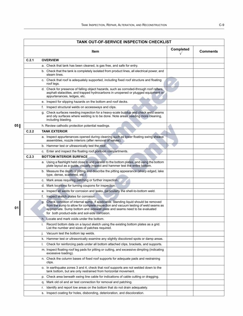
05
01
TANK INSPECTION, REPAIR, ALTERATION, AND RECONSTRUCTION C-9
For C
ommittee
Use O
nly
TANK OUT-OF-SERVICE INSPECTION CHECKLIST
Item Completed √ Comments
C.2.1 OVERVIEWa. Check that tank has been cleaned, is gas free, and safe for entry.
b. Check that the tank is completely isolated from product lines, all electrical power, and steam lines.
c. Check that roof is adequately supported, including fixed roof structure and floating roof legs.
d. Check for presence of falling object hazards, such as corroded-through roof rafters, asphalt stalactites, and trapped hydrocarbons in unopened or plugged equipment or appurtenances, ledges, etc.
e. Inspect for slipping hazards on the bottom and roof decks.
f. Inspect structural welds on accessways and clips.
g. Check surfaces needing inspection for a heavy-scale buildup and check weld seams and oily surfaces where welding is to be done. Note areas needing more cleaning, including blasting.
h. Review cathodic protection potential readings.
C.2.2 TANK EXTERIORa. Inspect appurtenances opened during cleaning such as lower floating swing sheave
assemblies, nozzle interiors (after removal of valves).
b. Hammer test or ultrasonically test the roof.
c. Enter and inspect the floating roof pontoon compartments.
C.2.3 BOTTOM INTERIOR SURFACEa. Using a flashlight held close to and parallel to the bottom plates, and using the bottom
plate layout as a guide, visually inspect and hammer test the entire bottom.
b. Measure the depth of pitting and describe the pitting appearance (sharp edged, lake type, dense, scattered, etc.)
c. Mark areas requiring patching or further inspection.
d. Mark locations for turning coupons for inspection.
e. Inspect all welds for corrosion and leaks, particularly the shell-to-bottom weld.
f. Inspect sketch plates for corrosion.
g. Check condition of internal sump, if applicable. Standing liquid should be removed from the sump to allow for complete inspection and vacuum testing of weld seams as appropriate. Sump bottom and sidewall plate and seams need to be evaluated for both product-side and soil-side corrosion.
h. Locate and mark voids under the bottom.
i. Record bottom data on a layout sketch using the existing bottom plates as a grid. List the number and sizes of patches required.
j. Vacuum test the bottom lap welds.
k. Hammer test or ultrasonically examine any slightly discolored spots or damp areas.
l. Check for reinforcing pads under all bottom attached clips, brackets, and supports.
m. Inspect floating roof leg pads for pitting or cutting, and excessive dimpling (indicating excessive loading).
n. Check the column bases of fixed roof supports for adequate pads and restraining clips.
o. In earthquake zones 3 and 4, check that roof supports are not welded down to the tank bottom, but are only restrained from horizontal movement.
p. Check area beneath swing line cable for indications of cable cutting or dragging.
q. Mark old oil and air test connection for removal and patching.
r. Identify and report low areas on the bottom that do not drain adequately.
s. Inspect coating for holes, disbonding, deterioration, and discoloration.

C-10 API STANDARD 653
For C
ommittee
Use O
nly
TANK OUT-OF-SERVICE INSPECTION CHECKLIST—Continued
Item Completed √ Comments
C.2.4 SHELL SEAMS AND PLATE
a. On cone up bottoms, closely inspect and gauge the depth of metal loss on the lower 2 in. to 4 in. of the shell (area of standing water).
b. Measure the depth of pitting on each course.
c. Inspect and estimate the amount of metal loss on the heads of rivets and bolts.
d. Inspect shell-to-bottom riveted lap joints.
e. Inspect for vertical grooving damage from seal assembly protrusions.
f. Inspect existing protective coatings for damage, deterioration, and disbonding.
g. Check for areas of rubbing (indicating too much pressure by the seal assembly shoes or inadequate annular space).
h. Visually inspect the shell plates and seams for indications of leakage.
i. If the shell has riveted or bolted seams, record the leak locations by film or chart in case the locations are lost during surface preparation for painting.
j. Measure annular space at 40-ft intervals.
k. Survey the shell to check for roundness and plumb.
C.2.5 SHELL-MOUNTED OVERFLOWS
a. Inspect overflow for corrosion and adequate screening.
b. Check location of overflow that it is not above any tank valves or equipment.
C.2.6 ROOF INTERIOR SURFACE
C.2.6.1 General
a. Visually inspect the underside surface of the roof plates for holes, scale buildup, and pitting.
b. Hammer test or ultrasonically examine to check for thin areas, particularly in the vapor space of floating roofs and at edge of roof on cone roof tank.
c. Check all clips, brackets, braces, etc., welded to the roof deck plate for welded reinforcing pads and see that they have not broken free.
d. If no pad is present, penetrant test for cracking of the weld or deck plate.
e. Inspect for protective coating for breaks, disbondment, and deterioration.
f. Spark test the interior surface coating if recoating is not planned.
C.2.6.2 Fixed Roof Support Structure
a. Inspect the support columns for thinning in the upper 2 ft.
b. On API columns (two channels welded together) check for corrosion scale breaking the tack welds, unless the joint between the channels is completely seal welded.
c. Check that the reinforcing pad on the bottom is seal-welded to the tank bottom with horizontal movement restraining clips welded to the pad.
d. Determine if pipe column supports are concrete filled or open pipe. If open pipe, check for a drain opening in the bottom of the pipe.
e. Inspect and gauge rafters for thinning, particularly near the center of the roof. Report metal loss.
f. Check for loose or twisted rafters.
g. Inspect girders for thinning and check that they are attached securely to the top of the columns.

TANK INSPECTION, REPAIR, ALTERATION, AND RECONSTRUCTION C-11
For C
ommittee
Use O
nly
TANK OUT-OF-SERVICE INSPECTION CHECKLIST—Continued
Item Completed √ Comments
h. Report if the columns have cross bracing in the area between the low pump out of the top of the shell (for future internal floating roof installation).
i. Inspect and report presence of any roof-mounted swing line bumpers.
j. Photograph the roof structure if no rafter layout drawing exists.
C.2.7 FIXED ROOF APPURTENANCES
C.2.7.1 Inspection and Light Hatches
a. Inspect the hatches for corrosion, paint and coating failures, holes, and cover sealing.
b. On loose covers, check for a safety chain in good condition.
c. On light hatches over 30 in. across, check for safety rods.
d. Inspect the condition of the gaskets on bold or latched down hatch covers.
C.2.7.2 Staging Support Connection
Inspect the condition of the staging support for corrosion.
C.2.7.3 Breathers and Vents
a. Inspect and service the breather.
b. Inspect screens on vents and breathers.
C.2.7.4 Emergency P/V Hatches
a. Inspect and service pressure/vacuum hatches. (Setting should be high enough to pre-vent chattering of breather during normal operation. See breather manufacturer’s guide.)
b. Inspect liquid seal hatches for corrosion and proper liquid level in the seal.
C.2.7.5 Sample Hatch
a. Inspect sample hatch for corrosion.
b. Check that the cover operates properly.
c. If the tank has no gauge well, check for a hold-off distance marker and check mea-surement.
C.2.8 FLOATING ROOF
C.2.8.1 Roof Deck
a. Hammer test the area between roof rim and shell. (If access for hammer testing is inadequate, measure the distance from the bottom edge of the roof to the corroded area and then hammer test from inside the pontoon.)
b. In sour water service, clean and test all deck plate weld seams for cracking unless the lower laps have been seal-welded.
c. Check that either the roof drain is open or the drain plug in the roof is open in case of unexpected rain.
d. On flat bottomed and cone bottom roof decks, check for a vapor dam around the periphery of the roof. The dam should be continuous without break to prevent escape of vapors to the seal area from under the center of the roof.
C.2.8.2 Floating Roof Pontoons
a. Visually inspect each pontoon for liquid leakage.
b. Run a light wire through the gooseneck vents on locked down inspection hatch covers to make sure they are open.
c. Inspect lockdown latches on each cover.

C-12 API STANDARD 653
For C
ommittee
Use O
nly
TANK OUT-OF-SERVICE INSPECTION CHECKLIST—Continued
Item Completed √ Comments
d. Check and report if each pontoon is:
1. Vapor tight (bulkhead seal welded on one side on bottom, sides, and top),
2. Liquid tight (seal-welded on bottom and sides only), or
3. Unacceptable (minimum acceptable condition is liquid tight).
C.2.8.3 Floating Roof Cutouts
a. Inspect underside of cutouts for mechanical damage.
b. Inspect welds for cracks.
c. Inspect plate for thinning, pitting, and erosion.
d. Measure mixer cutouts and record plate thickness for future mixer installation or replacement. Plate thickness ______ .
C.2.8.4 Floating Roof Supports
a. Inspect fixed low and removable high floating roof legs for thinning.
b. Inspect for notching at bottom of legs for drainage.
c. Inspect for leg buckling or felling at bottom.
d. Inspect pin hole in roof guide for tears.
e. Check plumb of all legs.
f. Inspect for adequate reinforcing gussets on all legs through a single portion of the roof.
g. Inspect the area around the roof legs for cracking if there is no internal reinforcing pad or if the topside pad is not welded to the deck plate on the underside.
h. Inspect the sealing system on the two-position legs and the vapor plugs in the fixed low leg for deterioration of the gaskets.
i. On shell-mounted roof supports, check for adequate clearance based on the maxi-mum floating roof movement as determined by the position of the roof relative to the gauge well and/or counter-rotational device.
C.2.9 FLOATING ROOF SEAL ASSEMBLIES
C.2.9.1 Primary Shoe Assembly
a. Remove four sections of foam log (foam-filled seals) for inspection on 90° locations.
b. Inspect hanger attachment to roof rim for thinning, bending, broken welds, and wear of pin holes.
c. Inspect clips welded to roof rim for thinning.
d. Shoes—inspect for thinning and holes in shoes.
e. Inspect for bit-metal bolts, clips, and attachments.
f. Seal fabric—inspect for deterioration, stiffening, holes, and tears in fabric.
g. Measure length of fabric from top of shoe to roof rim, and check against maximum anticipated annular space as roof operates.
h. Inspect any modification of shoes over shell nozzles, mixers, etc., for clearance.
i. Inspect shoes for damage caused by striking shell nozzles, mixers, etc.
C.2.9.2 Primary Toroidal Assembly
a. Inspect seal fabric for wear, deterioration, holes, and tears.

TANK INSPECTION, REPAIR, ALTERATION, AND RECONSTRUCTION C-13
For C
ommittee
Use O
nly
TANK OUT-OF-SERVICE INSPECTION CHECKLIST—Continued
Item Completed √ Comments
b. Inspect hold-down system for buckling or bending.
c. Inspect foam for liquid absorption and deterioration.
C.2.9.3 Rim-Mounted Secondaries
a. Inspect the rim-mounted bolting bar for corrosion and broken welds.
b. Measure and chart seal-to-shell gaps.
c. Visually inspect seam from below, looking for holes as evidenced by light.
d. Inspect fabric for deterioration and stiffness.
e. Inspect for mechanical damage, corrosion, and wear on tip in contact with shell.
f. Inspect for contact with obstructions above top of shell.
C.2.10 FLOATING ROOF APPURTENANCES
C.2.10.1 Roof Manways
a. Inspect walls of manways for pitting and thinning.
b. On tanks with interface autogauges, check seal around gauge tape cable and guide wires through manway cover.
c. Inspect cover gasket and bolts.
C.2.10.2 Rim Vent
a. Check rim vent for pitting and holes.
b. Check vent for condition of screen.
c. On floating roof tanks where the environmental rules require closing off the vent, check the vent pipe for corrosion at the pipe-to-rim joint and check that the blinding is adequate.
C.2.10.3 Vacuum Breaker, Breather Type
a. Service and check operation of breather valve.
b. Check that nozzle pipe projects no more than 1/2 in. below roof deck.
C.2.10.4 Vacuum Breaker, Mechanical Type
Inspect the stem for thinning. Measure how far the vacuum breaker cover is raised off the pipe when the roof is resting on high or low legs.
a. On high legs: _________ .
b. On low legs: _________ .
C.2.10.5 Roof Drains: Open Systems, Including Emergency Drains
a. Check liquid level inside open roof drains for adequate freeboard. Report if there is insufficient distance between liquid level and top of drain.
b. If tank comes under Air Quality Monitoring District rules, inspect the roof drain vapor plug.
c. If emergency drain is not at the center of the roof, check that there are at least three emergency drains.
C.2.10.6 Closed Drain Systems: Drain Basins
a. Inspect for thinning and pitting.
b. Inspect protective coating (topside).
c. Inspect basin cover or screen for corrosion.
d. Test operation of check valve.
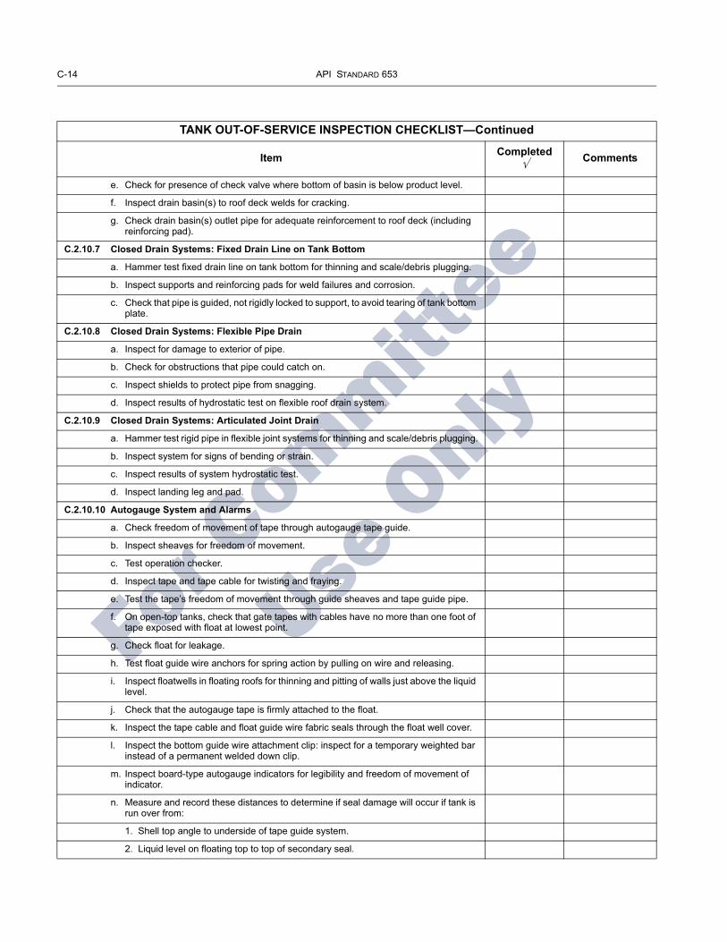
C-14 API STANDARD 653
For C
ommittee
Use O
nly
TANK OUT-OF-SERVICE INSPECTION CHECKLIST—Continued
Item Completed √ Comments
e. Check for presence of check valve where bottom of basin is below product level.
f. Inspect drain basin(s) to roof deck welds for cracking.
g. Check drain basin(s) outlet pipe for adequate reinforcement to roof deck (including reinforcing pad).
C.2.10.7 Closed Drain Systems: Fixed Drain Line on Tank Bottom
a. Hammer test fixed drain line on tank bottom for thinning and scale/debris plugging.
b. Inspect supports and reinforcing pads for weld failures and corrosion.
c. Check that pipe is guided, not rigidly locked to support, to avoid tearing of tank bottom plate.
C.2.10.8 Closed Drain Systems: Flexible Pipe Drain
a. Inspect for damage to exterior of pipe.
b. Check for obstructions that pipe could catch on.
c. Inspect shields to protect pipe from snagging.
d. Inspect results of hydrostatic test on flexible roof drain system.
C.2.10.9 Closed Drain Systems: Articulated Joint Drain
a. Hammer test rigid pipe in flexible joint systems for thinning and scale/debris plugging.
b. Inspect system for signs of bending or strain.
c. Inspect results of system hydrostatic test.
d. Inspect landing leg and pad.
C.2.10.10 Autogauge System and Alarms
a. Check freedom of movement of tape through autogauge tape guide.
b. Inspect sheaves for freedom of movement.
c. Test operation checker.
d. Inspect tape and tape cable for twisting and fraying.
e. Test the tape’s freedom of movement through guide sheaves and tape guide pipe.
f. On open-top tanks, check that gate tapes with cables have no more than one foot of tape exposed with float at lowest point.
g. Check float for leakage.
h. Test float guide wire anchors for spring action by pulling on wire and releasing.
i. Inspect floatwells in floating roofs for thinning and pitting of walls just above the liquid level.
j. Check that the autogauge tape is firmly attached to the float.
k. Inspect the tape cable and float guide wire fabric seals through the float well cover.
l. Inspect the bottom guide wire attachment clip: inspect for a temporary weighted bar instead of a permanent welded down clip.
m. Inspect board-type autogauge indicators for legibility and freedom of movement of indicator.
n. Measure and record these distances to determine if seal damage will occur if tank is run over from:
1. Shell top angle to underside of tape guide system.
2. Liquid level on floating top to top of secondary seal.

TANK INSPECTION, REPAIR, ALTERATION, AND RECONSTRUCTION C-15
For C
ommittee
Use O
nly
TANK OUT-OF-SERVICE INSPECTION CHECKLIST—Continued
Item Completed √ Comments
o. Identify floating roofs where the tape is connected directly to the roof.
p. Overfill alarm: Inspect tank overfill prevention alarm switches for proper operation.
C.2.11 COMMON TANK APPURTENANCES
C.2.11.1 Gauge Well
a. Inspect gate well pipe for thinning at about two-thirds distance above the bottom: look for thinning at the edge of the slots.
b. Check for corrosion on the pipe joint. Check that sample cords, weights, thermome-ters, etc., have been removed from the pipe.
c. Check for cone at bottom end of pipe about one foot above the bottom.
d. Check condition of well washer pipe and that its flared end is directed at the near side of the hold off pad.
e. Check that supports for gauge well are welded to pad or to shell and not directly to bottom plate.
f. Check operation of gauge well cover.
g. Check presence of a hold-off distance marker in well pipe and record hold-off distance. Hold-off distance _________ .
h. Identify and report size and pipe schedule, and whether pipe is solid or slotted. Report slot size.
i. Check that the hold-off distance plate is seal-welded to the bottom and that any gauge well supports are welded to the plate and not directly to the bottom.
j. Inspect vapor control float and cable.
k. Check for presence and condition of gauge well washer.
l. Check for bull plug or plate blind on gauge well washer valve.
m. Inspect gauge well guide in floating roof for pitting and thinning.
n. Inspect the guide rollers and sliding plates for freedom of movement.
o. Inspect condition of gauge well pipe seal system.
p. On black oil and diesel services: if gauge well is also used for sampling, check for presence of a thief- and gauge-type hatch to avoid spillage.
q. Visually inspect inside of pipe for pipe weld protrusions which could catch or damage vapor control float.
C.2.11.2 Sampling Systems: Roof Sample Hatches
a. Inspect roof-mounted sample hatches for reinforcing pads and cracking.
b. Inspect cover for operation.
c. For tanks complying with Air Quality Monitoring District rules, inspect sample hatch covers for adequate sealing.
d. Check horizontal alignment of internal floating roof sample hatches under fixed roof hatches.
e. Inspect the sealing system on the internal floating roof sample hatch cover.
f. Inspect floating roof sample hatch cover recoil reel and rope.
C.2.11.3 Shell Nozzles
a. Inspect shell nozzles for thinning and pitting.
b. Inspect hot tap nozzles for trimming of holes.

C-16 API STANDARD 653
For C
ommittee
Use O
nly
TANK OUT-OF-SERVICE INSPECTION CHECKLIST—Continued
Item Completed √ Comments
c. Identify type of shell nozzles.
d. Identify and describe internal piping, including elbow-up and elbow-down types.
C.2.11.4 For Nozzles Extended Into the Tank
a. Inspect pipe support pads welded to tank bottom.
b. Inspect to see that pipe is free to move along support without strain or tearing action on bottom plate.
c. Inspect nozzle valves for packing leaks and damaged flange faces.
d. Inspect heater stream nozzle flanges and valves for wire cutting.
e. Report which nozzles have thermal pressure relief bosses and valves.
f. In internal elbow-down fill line nozzles, inspect the wear plate on the tank bottom.
g. On elbow-up fill lines in floating roof tanks, check that opening is directed against underside of roof, not against vapor space. Inspect impact are for erosion.
C.2.11.5 Diffusers and Air Rolling Systems
a. Inspect diffuser pipe for erosion and thinning.
b. Check holes in diffuser for excessive wear and enlargement.
c. Inspect diffuser supports for damage and corrosion.
d. Check that diffuser supports restrain, not anchor, longitudinal line movement.
e. Inspect air spiders on bottom of lube oil tanks for plugging and damaged or broken threaded joints.
C.2.11.6 Swing Lines
a. Inspect flexible joint for cracks and leaks.
b. Scribe the flexible joint across the two moving faces and raise end of swing line to check the joint’s freedom of movement, indicated by separation of scribe marks.
c. Check that flexible joints over 6 in. are supported.
d. Inspect the swing pipe for deep pitting and weld corrosion.
e. Loosen the vent plugs in the pontoons and listen for a vacuum. Lack of a vacuum indicates a leaking pontoon.
f. Check the results of air test on pontoons during repairs.
g. Inspect the pontoons for pitting.
h. Inspect the pull-down cable connections to the swing.
i. Inspect the condition of the bottom-mounted support, fixed roof limiting bumper, or shell-mounted limiting bumper for wood condition, weld and bolt corrosion, and seal welding to bottom or shell.
j. Inspect safety hold-down chain for corrosion and weak links.
k. Check that there is a welded reinforcing pad where the chain connects to the bottom.
l. If the floating swing in a floating or internal floating roof tank does not have a limiting device preventing the swing from exceeding 60 degrees, measure and calculate the maximum angle possible with the roof on overflow. Max. angle on overflow _____________ . (If the calculated angle exceeds 65 degrees, recommended installation of a limiting bracket.)
m. Inspect pull-down cable for fraying.

TANK INSPECTION, REPAIR, ALTERATION, AND RECONSTRUCTION C-17
For C
ommittee
Use O
nly
TANK OUT-OF-SERVICE INSPECTION CHECKLIST—Continued
Item Completed √ Comments
n. Inspect for three cable clamps where cable attaches to end of swing line (single-reeved) or to roof assembly (double-reeved). Inspect sheaves for freedom of move-ment.
o. Inspect winch operation and check the height indicator for legibility and accuracy.
p. Inspect bottom-mounted sheave assembly at end of pontoon for freedom of rotation of sheave.
q. Inspect shell-mounted lower sheave assembly for freedom of rotation of sheave, corrosion thinning, and pitting of sheave housing.
r. Inspect upper sheave assembly for freedom of movement of sheave.
s. Inspect the cable counterbalance assembly for corrosion and freedom of operation.
C.2.11.7 Manway Heater Racks
a. Inspect the manway heater racks for broken welds and bending of the sliding rails.
b. Measure and record the length of the heater and length of the track.
C.2.11.8 Mixer Wear Plates and Deflector Stands
a. Inspect bottom and shell plates and deflector stands.
b. Inspect for erosion and corrosion on the wear plates. Inspect for rigidity, structural soundness, corrosion, and erosion of deck plates and reinforcing pads that are seal-welded to the bottom under the deflector stand legs.
c. Measure for propeller clearance between the bottom of deflector stand and roof when the roof is on low legs.
C.2.12 ACCESS STRUCTURES
C.2.12.1 Handrails
a. Identify and report type (steel pipe, galvanized pipe, square tube, angle) and size of handrails.
b. Inspect for pitting and holes, paint failure.
c. Inspect attachment welds.
d. Identify cold joints and sharp edges. Inspect the handrails and midrails.
e. Inspect safety drop bar (or safety chain) for corrosion, functioning, and length.
f. Inspect the handrail between the rolling ladder and the gaging platform for a hazard-ous opening when the floating roof is at its lowest level.
C.2.12.2 Platform Frame
a. Inspect frame for corrosion and paint failure.
b. Inspect the attachment of frame to supports and supports to tank for corrosion and weld failure.
c. Check reinforcing pads where supports are attached to shell or roof.
d. Inspect the surface that deck plate or grating rests on, for thinning and holes.
e. Check that flat-surface-to-flat-surface junctures are seal-welded.
C.2.12.3 Deck Plate and Grating
a. Inspect deck plate for corrosion-caused thinning or holes (not drain holes) and paint failure.
b. Inspect plate-to-frame weld for rust scale buildup.
c. Inspect grating for corrosion-caused thinning of bars and failure of welds.
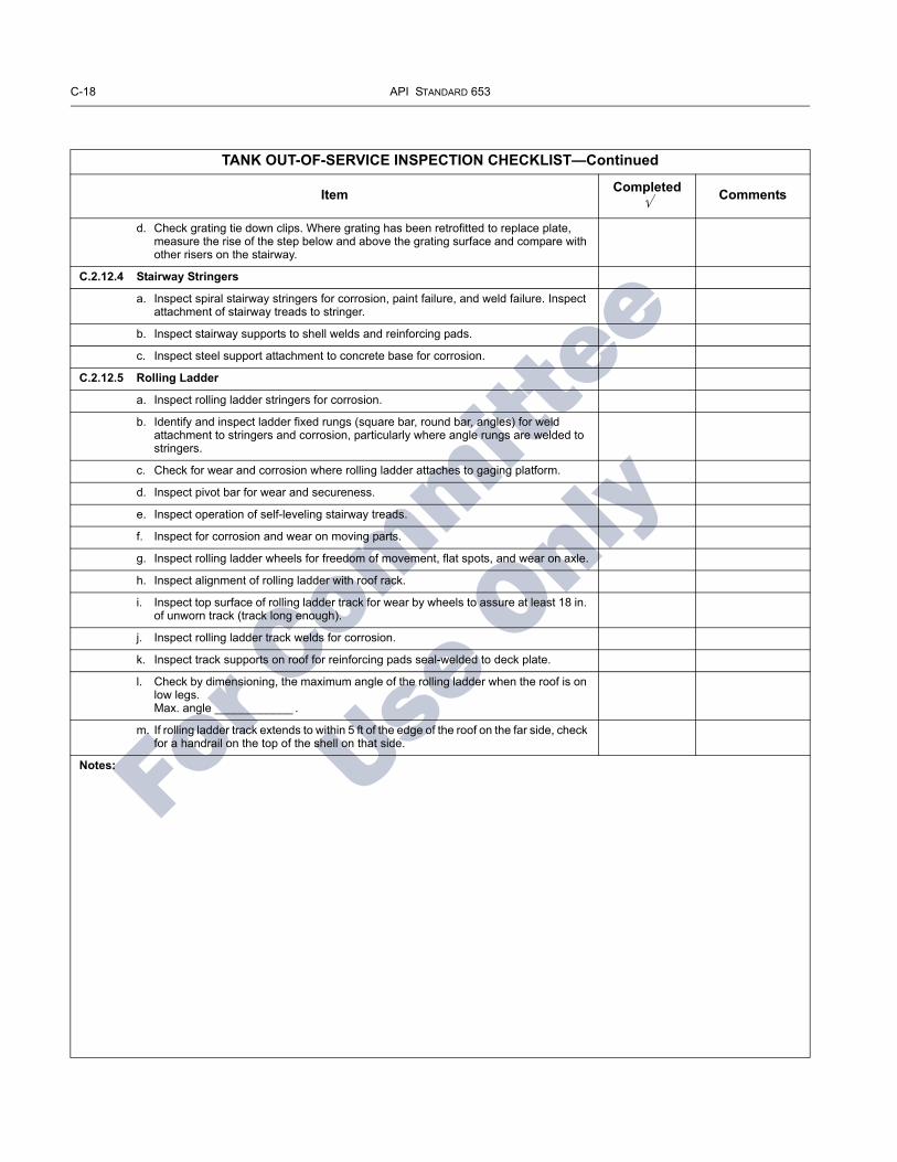
C-18 API STANDARD 653
For C
ommittee
Use O
nly
TANK OUT-OF-SERVICE INSPECTION CHECKLIST—Continued
Item Completed √ Comments
d. Check grating tie down clips. Where grating has been retrofitted to replace plate, measure the rise of the step below and above the grating surface and compare with other risers on the stairway.
C.2.12.4 Stairway Stringers
a. Inspect spiral stairway stringers for corrosion, paint failure, and weld failure. Inspect attachment of stairway treads to stringer.
b. Inspect stairway supports to shell welds and reinforcing pads.
c. Inspect steel support attachment to concrete base for corrosion.
C.2.12.5 Rolling Ladder
a. Inspect rolling ladder stringers for corrosion.
b. Identify and inspect ladder fixed rungs (square bar, round bar, angles) for weld attachment to stringers and corrosion, particularly where angle rungs are welded to stringers.
c. Check for wear and corrosion where rolling ladder attaches to gaging platform.
d. Inspect pivot bar for wear and secureness.
e. Inspect operation of self-leveling stairway treads.
f. Inspect for corrosion and wear on moving parts.
g. Inspect rolling ladder wheels for freedom of movement, flat spots, and wear on axle.
h. Inspect alignment of rolling ladder with roof rack.
i. Inspect top surface of rolling ladder track for wear by wheels to assure at least 18 in. of unworn track (track long enough).
j. Inspect rolling ladder track welds for corrosion.
k. Inspect track supports on roof for reinforcing pads seal-welded to deck plate.
l. Check by dimensioning, the maximum angle of the rolling ladder when the roof is on low legs. Max. angle ____________ .
m. If rolling ladder track extends to within 5 ft of the edge of the roof on the far side, check for a handrail on the top of the shell on that side.
Notes:

03
03
For Committee
Use O
nly
APPENDIX D—AUTHORIZED INSPECTOR CERTIFICATION
D.1 ExaminationA written examination to certify an authorized inspector
within the scope of API Std 653 shall be administered by a third party designated by API. The examination shall be based on the current API Std 653 Body of Knowledge as pub-lished by API.
D.2 CertificationD.2.1 An API Std 653 authorized inspector certificate will be issued when an applicant has successfully passed the API Std 653 certification examination, and satisfies the criteria for education and experience. Education and experience, when combined, shall be equal to at least one of the following:
a. A bachelor of science degree in engineering or technology plus 1 year of experience in supervision or performance of inspection activities as described in API Std 653.b. A 2-year degree or certificate in engineering or technol-ogy, plus 2 years of experience in the design, construction, repair, inspection, or operation of aboveground storage tanks, of which 1 year must be in supervision or performance of inspection activities as described in API Std 653.c. A high school diploma or equivalent, plus 3 years of expe-rience in the design, construction, repair, inspection, or operation of aboveground storage tanks, of which 1 year must be in supervision or performance of inspection activities as described in API Std 653.d. A minimum of 5 years of experience in the design, con-struction, repair, inspection, or operation of aboveground storage tanks, of which 1 year must be in supervision or per-formance of inspection activities as described in API Std 653.
D.2.2 An API certificate for an authorized inspector is valid for 3 years from its date of issuance.
D.2.3 An API Std 653 authorized inspector certificate is valid in all jurisdictions and any other location that accepts or other wise does not prohibit the use of API Std 653.
D.3 Certification AgencyThe American Petroleum Institute shall be the certifying
agency.
D.4 RetroactivityThe certification requirements of API Std 653 shall not be
retroactive or interpreted as applying before 12 months after the date of publication of this edition or addendum of API Std 653. The recertification requirements of API Std 653, Section D.5 shall not be retroactive or interpreted as apply-ing before 3 years after the date of publication of this edi-tion or addendum of API Std 653.
D.5 RecertificationD.5.1 Recertification is required three years from the date of issuance of the API Std 653 authorized inspector certifi-cate. Recertification by written examination will be required for authorized inspectors who have not been actively engaged as authorized inspectors within the most recent three-year certification period. Recertification exams will be in accor-dance with all of the provisions contained in API Std 653.
D.5.2 “Actively engaged” as an authorized inspector shall be defined as a minimum of 20 percent of time spent per-forming or supervising inspection activities as described in API Std 653 over the most recent 3-year certification period.
Note: Inspection activities common to other API inspection docu-ments (NDE, record keeping, review of welding documents, etc.) may be considered here.
D.5.3 Once every other recertification period (every six years), inspectors actively engaged as an authorized inspector shal demonstrate knowledge of revisions to API 653 that were instituted during the previous six years. This require-ment shall be effective six years from the inspector’s initial certification date. Inspectors who have not been actively engaged as an authorized inspector within the most recent three-year period shall recertify as required in D.5.1.
D-1

For C
ommittee
Use O
nly
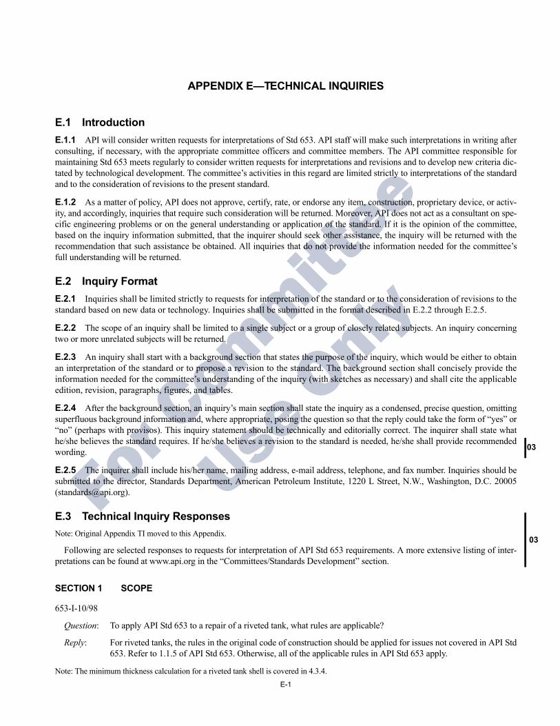
03
03
For C
ommittee
Use O
nly
APPENDIX E—TECHNICAL INQUIRIES
E.1 IntroductionE.1.1 API will consider written requests for interpretations of Std 653. API staff will make such interpretations in writing after consulting, if necessary, with the appropriate committee officers and committee members. The API committee responsible for maintaining Std 653 meets regularly to consider written requests for interpretations and revisions and to develop new criteria dic-tated by technological development. The committee’s activities in this regard are limited strictly to interpretations of the standard and to the consideration of revisions to the present standard.
E.1.2 As a matter of policy, API does not approve, certify, rate, or endorse any item, construction, proprietary device, or activ-ity, and accordingly, inquiries that require such consideration will be returned. Moreover, API does not act as a consultant on spe-cific engineering problems or on the general understanding or application of the standard. If it is the opinion of the committee, based on the inquiry information submitted, that the inquirer should seek other assistance, the inquiry will be returned with the recommendation that such assistance be obtained. All inquiries that do not provide the information needed for the committee’s full understanding will be returned.
E.2 Inquiry FormatE.2.1 Inquiries shall be limited strictly to requests for interpretation of the standard or to the consideration of revisions to the standard based on new data or technology. Inquiries shall be submitted in the format described in E.2.2 through E.2.5.
E.2.2 The scope of an inquiry shall be limited to a single subject or a group of closely related subjects. An inquiry concerning two or more unrelated subjects will be returned.
E.2.3 An inquiry shall start with a background section that states the purpose of the inquiry, which would be either to obtain an interpretation of the standard or to propose a revision to the standard. The background section shall concisely provide the information needed for the committee’s understanding of the inquiry (with sketches as necessary) and shall cite the applicable edition, revision, paragraphs, figures, and tables.
E.2.4 After the background section, an inquiry’s main section shall state the inquiry as a condensed, precise question, omitting superfluous background information and, where appropriate, posing the question so that the reply could take the form of “yes” or “no” (perhaps with provisos). This inquiry statement should be technically and editorially correct. The inquirer shall state what he/she believes the standard requires. If he/she believes a revision to the standard is needed, he/she shall provide recommended wording.
E.2.5 The inquirer shall include his/her name, mailing address, e-mail address, telephone, and fax number. Inquiries should be submitted to the director, Standards Department, American Petroleum Institute, 1220 L Street, N.W., Washington, D.C. 20005 ([email protected]).
E.3 Technical Inquiry ResponsesNote: Original Appendix TI moved to this Appendix.
Following are selected responses to requests for interpretation of API Std 653 requirements. A more extensive listing of inter-pretations can be found at www.api.org in the “Committees/Standards Development” section.
SECTION 1 SCOPE
653-I-10/98
Question: To apply API Std 653 to a repair of a riveted tank, what rules are applicable?
Reply: For riveted tanks, the rules in the original code of construction should be applied for issues not covered in API Std 653. Refer to 1.1.5 of API Std 653. Otherwise, all of the applicable rules in API Std 653 apply.
Note: The minimum thickness calculation for a riveted tank shell is covered in 4.3.4.
E-1
E-2 API STANDARD 653
05
03
For C
ommittee
Use O
nly
653-I-12/03
Question: When a tank is partially built and completed by the same or another fabricator after an extended period of time, which standard governs the finished tank, API 650 or API 653?
Reply: API 653 only applies to tanks that have been built and placed in service (see 1.1.1). Therefore, the tank will need to comply with all of the requirements of API 650.
SECTION 4 SUITABILITY FOR SERVICE
653-I-04/01
Question: Given that an inspection in accordance with API Std 653 is pending for selected tanks constructed in accordance with the 7th Edition of API Std 650, are these tanks required by API Std 653 to be upgraded to meet the require-ments of the current (11th) edition of API Std 650?
Reply: No. However, if there is a change in service involved, or there is a reconstruction, repair, or alteration required, then the requirements in API Std 653 generally invoke the current edition of API Std 650 for the evaluation/con-struction work required. Refer to the appropriate sections in API Std 653.
SECTION 4.4.3 MAXIMUM THICKNESS CALCULATION FOR WELDED TANK SHELL
653-I-09/00
Question 1: When evaluating the retirement thickness in a corroded plate away from welds at a distance of at least the greater of one inch or twice the plate thickness, should a joint efficiency of E = 1.0 to be used?
Reply 1: Yes.
Question 2: If the joint efficiency E, for an existing tank is less than 1.0, should this value for E be used in calculating the min-imum required thickness of the tank?
Reply 2: Yes.
SECTION 4.2.4 CHANGE OF SERVICE
653-I-10/00
Question: Shall the design requirements of the latest edition of API Std 650 be considered for tanks that will have their oper-ating temperature increased above 200°F?
Reply: Yes. See Sections 1.1.5 and 4.2.4.3.
653-I-03/01
Question 1: An existing tank greater than 100 ft in diameter with a lap-welded bottom is currently in heated service (> 200°F). This tank is removed from service for a routine internal inspection. Does this tank have to be retrofitted with an annular ring per API Std 650, Section M.4?
Reply 1: Yes. See Sections 1.1.5 and 4.2.4.3.
Question 2: An existing tank greater than 100 ft in diameter with a lap-welded bottom is being changed to heated service. Does API Std 653, 4.3.3.4 require this tank to be retrofitted with an annular ring per API Std 650, M.4.1? Or is it accept-able to evaluate the tank per M.4.2 to determine if stresses, minimum fill height, and fill/empty cycles will be acceptable with the existing lap welded bottom?
Reply 2: Yes. See Sections 1.1.5 and 4.2.4.3.
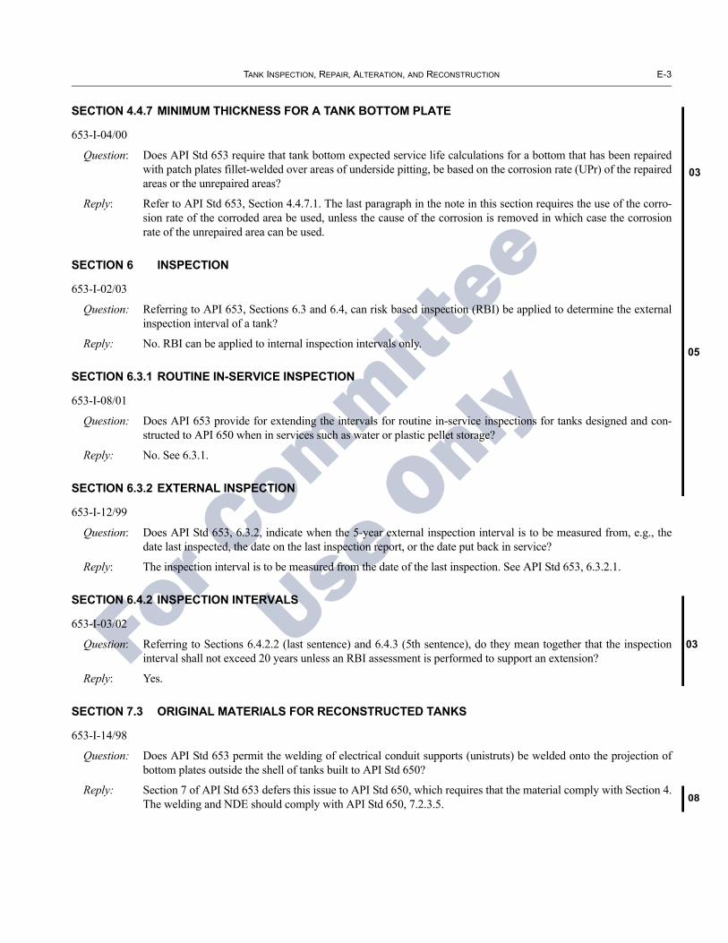
TANK INSPECTION, REPAIR, ALTERATION, AND RECONSTRUCTION E-3
03
05
03
08
For C
ommittee
Use O
nly
SECTION 4.4.7 MINIMUM THICKNESS FOR A TANK BOTTOM PLATE
653-I-04/00
Question: Does API Std 653 require that tank bottom expected service life calculations for a bottom that has been repaired with patch plates fillet-welded over areas of underside pitting, be based on the corrosion rate (UPr) of the repaired areas or the unrepaired areas?
Reply: Refer to API Std 653, Section 4.4.7.1. The last paragraph in the note in this section requires the use of the corro-sion rate of the corroded area be used, unless the cause of the corrosion is removed in which case the corrosion rate of the unrepaired area can be used.
SECTION 6 INSPECTION
653-I-02/03
Question: Referring to API 653, Sections 6.3 and 6.4, can risk based inspection (RBI) be applied to determine the external inspection interval of a tank?
Reply: No. RBI can be applied to internal inspection intervals only.
SECTION 6.3.1 ROUTINE IN-SERVICE INSPECTION
653-I-08/01
Question: Does API 653 provide for extending the intervals for routine in-service inspections for tanks designed and con-structed to API 650 when in services such as water or plastic pellet storage?
Reply: No. See 6.3.1.
SECTION 6.3.2 EXTERNAL INSPECTION
653-I-12/99
Question: Does API Std 653, 6.3.2, indicate when the 5-year external inspection interval is to be measured from, e.g., the date last inspected, the date on the last inspection report, or the date put back in service?
Reply: The inspection interval is to be measured from the date of the last inspection. See API Std 653, 6.3.2.1.
SECTION 6.4.2 INSPECTION INTERVALS
653-I-03/02
Question: Referring to Sections 6.4.2.2 (last sentence) and 6.4.3 (5th sentence), do they mean together that the inspection interval shall not exceed 20 years unless an RBI assessment is performed to support an extension?
Reply: Yes.
SECTION 7.3 ORIGINAL MATERIALS FOR RECONSTRUCTED TANKS
653-I-14/98
Question: Does API Std 653 permit the welding of electrical conduit supports (unistruts) be welded onto the projection of bottom plates outside the shell of tanks built to API Std 650?
Reply: Section 7 of API Std 653 defers this issue to API Std 650, which requires that the material comply with Section 4. The welding and NDE should comply with API Std 650, 7.2.3.5.

E-4 API STANDARD 653
08
For C
ommittee
Use O
nly
SECTION 8.4 SHELL DESIGN
653-I-06/99
Background: API Std 653 2nd Edition, Addendum 2, 6.4.2 requires the use of hydrostatic stresses (St) from API Std 650, Table 5-2. Prior to the issuance of Addendum 2 of API Std 653, the formulas in API Stds 650 and 653 were the same except for the joint factor (E) contained in the API Std 653 formula.
A reconstructed tank with its original weld (or riveted) joints must maintain the joint efficiency of its original construction. API Std 653 requires the design and hydrostatic stresses from API Std 650 be used for reconstructed tanks. This indicates that the formulas from API Std 650 should also be used for design and hydrostatic testing of a reconstructed tank. The addition of a joint factor is required if original joints remain in the tank. If all old joints are removed, the current API Std 650 design formula may be used. Since API Stds 650 and 653 formulae were the same before Addendum 2, this posed no problem.
Question 1: Now that there is a difference in the formulas (dropping the “1” from the API Std 653 formula), is it the intent of API Std 653 that the API Std 650 formula (below) with an “E”, added for the joint efficiency, be used when a reconstructed tank is involved?
td2.6D H 1–( )G
SdE---------------------------------- CA+=
Reply 1: Yes.
Question 2: Is it the intent of API Std 653 that the API Std 650 formula for the hydrostatic test height be used when a recon-structed tank is involved?
Reply 2: Yes.
Question 3: Did the committee intend that the formula given in API Std 653 with allowable stresses for a new tank from API Std 650 be used for the design of a reconstructed tank?
Reply 3: No. The committee is currently considering an agenda item to modify API Std 653 to avoid this confusion. Changes resulting from this agenda item will appear in a future edition or addendum to API Std 653.
SECTION 9.1 TANK REPAIR AND ALTERATION
653-I-09/98
Question: A tank has been repaired and hydrotested according to the requirements of API Std 653. Following the hydrotest, a condition not complying with API Std 653 is discovered, e.g. a weld spacing being too small, that was not iden-tified prior to testing. Is this tank acceptable for service?
Reply: At the time the tank repair and testing was completed the tank is acceptable for service per API Std 653, assuming there was no prior knowledge of the noncompliant condition. If the condition was identified after hydrotesting, that condition must be evaluated and handled as required by the tank owner/operator and the local jurisdiction.
653-I-03/00
Question 1: With reference to API Std 653, does an authorized inspector have to be on site during reconstruction, repairs and alterations?
Reply 1: No, but the authorized inspector is required to be on the site for the external and internal inspections required by API Std 653, 6.
Question 2: Can a company have more than one API Std 653 Inspector under the same inspector authorization number?
Reply 2: No.
Question 3: Is an API Std 653 inspector qualified to inspect site construction for “new” API Std 650 tanks?
Reply 3: API Std 653, and its inspector certification program, does not apply to new construction per API Std 650.
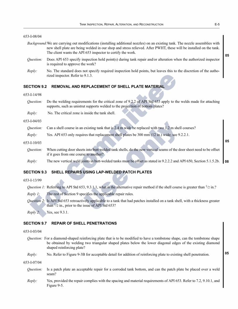
TANK INSPECTION, REPAIR, ALTERATION, AND RECONSTRUCTION E-5
05
05
08
05
For C
ommittee
Use O
nly
653-I-08/04
Background:We are carrying out modifications (installing additional nozzles) on an existing tank. The nozzle assemblies with new shell plate are being welded in our shop and stress relieved. After PWHT, these will be installed on the tank. The client wants the API 653 inspector to certify the work.
Question: Does API 653 specify inspection hold point(s) during tank repair and/or alteration when the authorized inspector is required to approve the work?
Reply: No. The standard does not specify required inspection hold points, but leaves this to the discretion of the autho-rized inspector. Refer to 9.1.3.
SECTION 9.2 REMOVAL AND REPLACEMENT OF SHELL PLATE MATERIAL
653-I-14/98
Question: Do the welding requirements for the critical zone of 9.2.2 of API Std 653 apply to the welds made for attaching supports, such as unistrut supports welded to the projection of bottom plates?
Reply: No. The critical zone is inside the tank shell.
653-I-04/03
Question: Can a shell course in an existing tank that is 2.4 m wide be replaced with two 1.2 m shell courses?
Reply: Yes. API 653 only requires that replacement shell plates be 300 mm (12 in.) wide; see 9.2.2.1.
653-I-10/03
Question: When cutting door sheets into butt welded tank shells, do the new vertical seams of the door sheet need to be offset if it goes from one course to another?
Reply: The new vertical weld joints in butt-welded tanks must be offset as stated in 9.2.2.2 and API 650, Section 5.1.5.2b.
SECTION 9.3 SHELL REPAIRS USING LAP-WELDED PATCH PLATES
653-I-13/99
Question 1: Referring to API Std 653, 9.3.1.1, what is the alternative repair method if the shell course is greater than 1/2 in.?
Reply 1: The rest of Section 9 specifies the applicable repair rules.
Question 2: Is API Std 653 retroactively applicable to a tank that had patches installed on a tank shell, with a thickness greater than 1/2 in., prior to the issue of API Std 653?
Reply 2: Yes, see 9.3.1.
SECTION 9.7 REPAIR OF SHELL PENETRATIONS
653-I-03/04
Question: For a diamond-shaped reinforcing plate that is to be modified to have a tombstone shape, can the tombstone shape be obtained by welding two triangular shaped plates below the lower diagonal edges of the existing diamond shaped reinforcing plate?
Reply: No. Refer to Figure 9-3B for acceptable detail for addition of reinforcing plate to existing shell penetration.
653-I-07/04
Question: Is a patch plate an acceptable repair for a corroded tank bottom, and can the patch plate be placed over a weld seam?
Reply: Yes, provided the repair complies with the spacing and material requirements of API 653. Refer to 7.2, 9.10.1, and Figure 9-5.
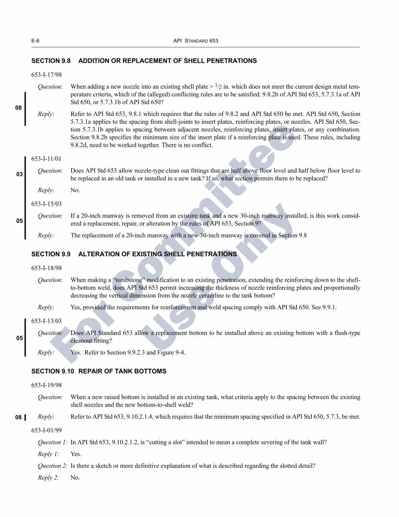
E-6 API STANDARD 653
08
03
05
05
08
For C
ommittee
Use O
nly
SECTION 9.8 ADDITION OR REPLACEMENT OF SHELL PENETRATIONS
653-I-17/98
Question: When adding a new nozzle into an existing shell plate > 1/2 in. which does not meet the current design metal tem-perature criteria, which of the (alleged) conflicting rules are to be satisfied: 9.8.2b of API Std 653, 5.7.3.1a of API Std 650, or 5.7.3.1b of API Std 650?
Reply: Refer to API Std 653, 9.8.1 which requires that the rules of 9.8.2 and API Std 650 be met. API Std 650, Section 5.7.3.1a applies to the spacing from shell-joints to insert plates, reinforcing plates, or nozzles. API Std 650, Sec-tion 5.7.3.1b applies to spacing between adjacent nozzles, reinforcing plates, insert plates, or any combination. Section 9.8.2b specifies the minimum size of the insert plate if a reinforcing plate is used. These rules, including 9.8.2d, need to be worked together. There is no conflict.
653-I-11/01
Question: Does API Std 653 allow nozzle-type clean out fittings that are half above floor level and half below floor level to be replaced in an old tank or installed in a new tank? If so, what section permits them to be replaced?
Reply: No.
653-I-15/03
Question: If a 20-inch manway is removed from an existing tank and a new 30-inch manway installed, is this work consid-ered a replacement, repair, or alteration by the rules of API 653, Section 9?
Reply: The replacement of a 20-inch manway with a new 30-inch manway is covered in Section 9.8
SECTION 9.9 ALTERATION OF EXISTING SHELL PENETRATIONS
653-I-18/98
Question: When making a “tombstone” modification to an existing penetration, extending the reinforcing down to the shell-to-bottom weld, does API Std 653 permit increasing the thickness of nozzle reinforcing plates and proportionally decreasing the vertical dimension from the nozzle centerline to the tank bottom?
Reply: Yes, provided the requirements for reinforcement and weld spacing comply with API Std 650. See 9.9.1.
653-I-13/03
Question: Does API Standard 653 allow a replacement bottom to be installed above an existing bottom with a flush-type cleanout fitting?
Reply: Yes. Refer to Section 9.9.2.3 and Figure 9-4.
SECTION 9.10 REPAIR OF TANK BOTTOMS
653-I-19/98
Question: When a new raised bottom is installed in an existing tank, what criteria apply to the spacing between the existing shell nozzles and the new bottom-to-shell weld?
Reply: Refer to API Std 653, 9.10.2.1.4, which requires that the minimum spacing specified in API Std 650, 5.7.3, be met.
653-I-01/99
Question 1: In API Std 653, 9.10.2.1.2, is “cutting a slot” intended to mean a complete severing of the tank wall?
Reply 1: Yes.
Question 2: Is there a sketch or more definitive explanation of what is described regarding the slotted detail?
Reply 2: No.

TANK INSPECTION, REPAIR, ALTERATION, AND RECONSTRUCTION E-7
08
05
08
05
08
For C
ommittee
Use O
nly
Question 3: Is there any provision in API Std 653 for a shell to-bottom weld (for a replacement bottom) that could be welded from the inside of the tank?
Reply 3: No. Two-sided welding is required. See API Std 653, 9.10.2.3 which refers to API Std 650 (including 5.1.5.7 of API Std 650).
653-I-01/00
Question: Referring to API Std 653, Figure 9-5 and 9.10, can a patch be placed near a three-point seam as shown below?
Weld Seam
3-point lap
Weld Seam
3-point lap
Reply: Yes, unless the patch plate covers the 3-point lap. See Note 5 in Fig. 9-5.
653-I-05/03
Question: When a new bottom is installed in an existing tank do the rules for pad plates in Section 9.10.3 apply?
Reply: Section 9.10.3 applies to pad plates installed during a new bottom installation in an existing tank
653-I-15/03
Question 1: Is removal of an existing bottom plate and replacement with a new plate allowed in Section 9.10.1?
Reply 1: The standard does not address replacement of a single bottom plate. This item has been referred to the appropriate committee.
Question 2: When replacing an entire bottom plate, or portion thereof, not in the critical zone, does API Standard 653 specify a minimum plate width required?
Reply 2: The standard does not address replacement of a single bottom plate.
653-I-16/03
Question 1: Can nozzles that are required to be raised by 9.10.2.1.4 be modified in accordance with 9.9?
Reply 1: Yes. The nozzles would have to meet the requirements of 9.10.2.1.5 and API 650, Section 5.7.3. Refer to API 653, Section 9.9.2.
Question 2: When shell nozzles that require stress relief are modified in accordance with 9.9.2.2 and/or 9.10.2.1.5, can the required stress relief be performed with the nozzle in the tank shell?
Reply 2: No. Refer to API 650, Sections 5.7.4.3, and 5.7.4.2.
SECTION 9.14 HOT TAPS
653-I-11/00
Question 1: Referring to API Std 653, is there any problem and concern with applying the hot-tapping method to 18 in. and larger connections?

E-8 API STANDARD 653
03
For C
ommittee
Use O
nly
Reply 1: Refer to 9.14.1.1, which limits hot-tapping to nozzles 18 NPS maximum, with additional limitations as noted. API does not publish the rational for the technical requirements in its standards.
Question 2: If we apply the hot-tapping method to 18 in. and larger connections, is it required to do PWHT to the nozzle neck?
Reply 2: API Std 653 does not permit hot-tapping sizes over 18 NPS. See 9.14.1.1.
653-I-09/01
Background:API Std 653 specifies a minimum shell plate thickness of 1/4 in. is required to install a 2-inch hot tap. We must install hot taps on some tanks in which the shell thickness is less than 1/4 in. The tanks are approximately 50 years old.
Question: Does API Std 653 allow hot tapping NPS 2 connections in tank shells less than 1/4 inch thick when the material is of unknown toughness?
Reply: Yes, if the thickness is not less than 3/16 inch. Refer to Table 9-1 and to Section 9.14.1 for further restrictions.
SECTION 10.5 DIMENSIONAL TOLERANCES
653-I-06/98
Question: Would it be correct to assess planar tilt and calculate limits via use of the plumbness rules in API Std 653, 10.5.2?
Reply: API Std 653 has no rules on tilt of existing tank shells, per se. The only tolerances applicable to reconstructed tank shells are for plumbness, roundness, peaking, and banding, as defined in 10.5. However, 10.5.6 provides rules that in effect specify the permitted planar tilt of the foundation. Also, refer to Appendix B, B.2.2.2, which provides guidelines on rigid body tilting.
653-I-14/99
Question 1: Are the foundation tolerances in API Std 653, 10.5.6, applicable only to reconstructed tanks or repairs on tank foundations originally constructed to the tolerances of API Std 650, 5.5.5, and Appendix B?
Reply 1: Yes.
Question 2: Are the foundation tolerances in API Std 653, 10.5.6, applicable to re-leveling tanks when the original tank foun-dation was constructed to the tolerances of API Std 650, 5.5.5, and Appendix B?
Reply 2: No. The foundation tolerances in API Std 653, 10.5.6 apply only to reconstructed tanks and do not apply to re-lev-eling existing tanks. Sections 12.3.1.2 and 12.3.2.5 provide requirements on re-leveling work.
SECTION 12 EXAMINATION AND TESTING
653-I-09/99
Question: Consider a tank built in the 1950s to API 12C rules, but having vertical and horizontal welds that will not pass the API 12C radiography criteria. If only the vertical welds were repaired, can the tank be put back in service meeting the API Std 653 requirements?
Reply: The horizontal and vertical welds examined must be evaluated/repaired based on the rules in API Std 650, 7.6, and API Std 653, Section 12, before placing the tank back in service.
SECTION 12.1 NONDESTRUCTIVE EXAMINATIONS
653-I-08/98
Question: Does API Std 653, 12.1.4.2, in its entirety, apply only to attachments welded to Groups IV through VI material?
Reply: Yes.

TANK INSPECTION, REPAIR, ALTERATION, AND RECONSTRUCTION E-9
03
03
05
03
For C
ommittee
Use O
nly
653-I-04/02
Question: Does API Std 653 require radiographic tracer shots on repairs of new shell plate to new shell plate welds and newshell plate to old shell plate as is required in new construction repairs with API Std 650.
Reply: Yes. See Section 12.1.1.3.
SECTION 12.2.1 NUMBER AND LOCATION OF RADIOGRAPHS
653-I-05/00
Question: With justifiable cause and at the request of the owner, is it allowable to substitute the RT in Section 12.2.1 of APIStd 653 with UT?
Reply: No.
SECTION 12.3 HYDROSTATIC TESTING
653-I-15/98
Question 1: Does API have any thoughts as to when it is infeasible to get water for hydrotesting?
Reply 1: The API Pressure Vessels & Tanks Subcommittee is strictly limited to interpretations of API Std 650 requirementsand to the consideration of revisions to the present standard based on new data or technology.
Question 2: Are there any tank testing methods, as an alternative to those specified in API Std 650, that one might consider ina variance situation with a state’s tank law, such as welding shut vents and using helium under a few pounds ofpressure, providing leak detection and stressing the tank as well?
Reply 2: API does not act as a consultant on specific engineering problems or on the general understanding or applicationof its standards. API’s activities in regard to technical inquiries are limited strictly to interpretations of the standardand to the consideration of revisions to the present standard based on new data or technology.
653-I-01/01
Question: To meet the requirements of a hydrostatic test exemption per API Std 653, Section 12.3.2.1(a), must all repairs bereviewed, or just the items that are covered in the scope of the major repair?
Reply: Section 12.3.2.1(a) applies only to the items within the scope of the major repair.
SECTION 12.5 MEASURED SETTLEMENT DURING HYDROSTATIC TESTING
653-I-11/02
Question: Is a settlement survey required during hydrostatic testing as described in Section 12.5?
Reply: Yes, settlement shall be measured during and when water reaches 100 percent of the test level; see 12.5.2.
SECTION 13 MARKING AND RECORDKEEPING
653-I-10/01
Background:We are working with API 653-certified inspectors to perform API Std 653 inspection services for various clients.A question has arisen over whether monthly “routine in-service inspection” records are to be kept for the life ofthe tank, or whether some shorter retention interval, such as 10 years, might be considered adequate.
Question: How long does API Std 653, Section 11, require inspection records to be retained?
Reply: API Std 653 does not specify the retention period.

For C
ommittee
Use O
nly

01
08
08
03
0108
0108
08
01
01
03
01
08
01
08
01
08
01
0801
01
For C
ommittee
Use O
nly
APPENDIX F—NDE REQUIREMENTS SUMMARY
F.1 IntroductionThis appendix is a summary of all nondestructive exami-
nation requirements for repairs and reconstruction of tanks. It is provided only as a guide to assure that the proper exam-inations are performed and that the acceptance standards, examiner qualifications, and procedure requirements are followed.
F.2 Visual ExaminationF.2.1 Visual examinations are required for:
a. Cavities from removal of repads (see API Std 653, 12.1.2.2).b. Completed welds of stress-relieved assemblies after stress relief but before hydrostatic testing (see API Std 653, 12.1.2.4).c. All fillet welds and completed repairs of fillet welds (see API Std 650, 7.3.2.2 and API Std 653, 12.1.3.3).d. Completed welds of new permanent attachments and areas of removed temporary attachments (see API Std 653, 12.1.4.2).e. New shell plate-to-shell plate welds (see API Std 653, 12.1.5).f. Tack welds left in place (see API Std 650, 7.2.1.8).g. Bottom plate and all welds, including the weld attaching a patch plate to the bottom, for new bottom plates (see API Std 653, 12.1.7.1).h. Root and final weld pass of patch plate to bottom in the critical zone (see API Std 653, 12.1.7.2).i. Areas of a bottom plate repaired by welding (See API Std 653, 12.1.7.3).j. Areas of a shell plate to be repaired by welding (See API Std 653, 12.1.8). k. Cavities from removal of weld defects (see API Std 653, 12.1.3.1).l. Annular plate butt-welds root pass and final pass (see API Std 653, 12.3.2.4.1b). m. Repaired areas of the shell-to-bottom weld (see API Std 653, 12.3.2.5.2).
F.2.2 The examination acceptance standard is API Std 650, 8.5.
F.2.3 There are no requirements for examiner qualifica-tions.
F.2.4 There are no procedure requirements.
F.3 Magnetic Particle and Liquid Penetrant Examination
F.3.1 Magnetic particle or liquid penetrant examinations are required for:
a. Cavities from removing existing reinforcing pad welds (see API Std 653, 12.1.2.2).b. New welds of nozzle neck-to-shell, nozzle neck-to-repad, and repad-to-shell (see API Std 653, 12.1.2.3).c. Completed welds of stress-relieved assemblies after stress relief, before hydrostatic testing (see API Std 653, 12.1.2.4).d. Cavities from removal of weld defects (see API Std 653, 12.1.3.1).e. Completed welds of new permanent attachments and areas of removed temporary attachments on API Std 650 material groups IV, IVA, V, or VI (see API Std 653, 12.1.4.2).f. The back-gouged surface of the root pass and the final sur-face of new shell plate welds where the shell is thicker than 1 in. (see API Std 653, 12.1.5).g. Existing shell-to-bottom welds that will be under a patch plate, plus 6 in. on each side (see API Std 653, 12.1.6.3).h. Root and final weld pass of patch plate to bottom in the critical zone (see API Std 653, 12.1.7.2).i. Bottom plate restored by welding (see API Std 653, 12.1.7.3).j. Areas of a shell plate repaired by welding (see API Std 653, 12.1.8).k. MT or PT repairs to the annular plate or bottom plates within the critical zone after root and final pass (see API Std 653, 12.3.2.4.1b).l. MT or PT repairs to the shell-to-bottom welds before and after root pass, and after final pass (see API Std 653, 12.3.2.5.2).m. The back-gouged surface of the root pass of full penetra-tion nozzle neck-to-shell and repad welds as required by API Std 653, 12.3.2.3.6, specific hydrostatic test exemption requirement.n. The back-gouged surface of the root pass and final surface of new vertical and horizontal shell joints as required by API Std 653, 12.3.2.3.5, specific hydrostatic test exemption requirement.
F.3.2 Magnetic particle examination alone is required for weld removal areas of the bottom-to-shell welds when removing a bottom (see API Std 653, 9.10.2.2 b).
F.3.3 The magnetic particle examination acceptance stan-dard is ASME Section V, Article 7. The acceptance standards for the removal and repair of defects shall be in accordance with ASME Section VIII, Appendix 6, paragraphs 6-3, 6-4, and 6-5.
F-1

F-2 API STANDARD 653
01
010801
08
08
01
01
08
01
08
01
08
01
0801
01
01
08
01
01
01
01
08
For C
ommittee
Use O
nly
F.3.4 The liquid penetrant examination acceptance stan-dards is ASME Section V, Article 6. The acceptance stan-dards for the removal and repair of defects shall be in accordance with ASME Section VIII, Appendix 8, para-graphs 8-3, 8-4, and 8-5.
F.3.5 The requirements for examiner qualifications shall follow API Std 650, 8.2.3, requiring an examiner with ade-quate vision and competent in the examination, interpreta-tion, and evaluation of results.
F.3.6 Procedure requirements shall follow ASME Sec-tion V.
F.4 Ultrasonic ExaminationF.4.1 Ultrasonic examinations are required for:
a. Shell areas over which lap patch plates are to be welded (see API Std 653, 9.3.1.9).b. Shell areas over which new reinforcing or hot tap nozzles are to be welded (see API Std 653, 12.1.2.1).c. Completed repairs of butt-welds unless radiographed (see API Std 653, 12.1.3.2).d. The full penetration nozzle neck-to-shell and repad welds as required by API Std 653, 12.3.2.3.6, specific hydrostatic test exemption requirement. e. Repairs to annular plate butt-welds after final pass (see API Std 653, 12.3.2.4.1b).
F.4.2 The ultrasonic examination acceptance standard shall be agreed upon by the owner/operator and contractor (see API Std 650, 8.3.2.5).
F.4.3 The requirements for examiner qualifications shall follow ASNT Level II or III, according to ASNT SNT-TC-1A. Level I personnel may be used if they are given written acceptance/rejection criteria prepared by Level II or Level III personnel, and are under the direct supervision of Level II or Level III personnel.
F.4.4 Procedure requirements shall follow ASME Sec-tion V.
F.5 Vacuum Box TestingF.5.1 Vacuum box testing is required for:
a. New shell-to-bottom welds, unless diesel tested (see API Std 653, 12.1.6).b. New bottom welds, unless tracer gas tested (see API Std 653, 12.1.7).c. New roof plate welds for tanks designed to be gas tight (see API Std 650, 7.3.7).
d. Potential bottom plate leak paths, (see API Std 653, 12.1.7.1).e. Patch plates welded on to the bottom, (see API Std 653, 12.1.7.1 and 12.1.7.2).f. Bottom plate restored by welding (see API Std 653, 12.1.7.3).
F.5.2 The requirements for examiner qualifications shall follow API Std 650, 8.6.4, requiring an examiner with ade-quate vision and competence in the examination method, interpretation, and evaluation of results.
F.5.3 Procedure requirements shall follow API Std 650, 8.6 (3 lbf/in.2 gauge minimum).
F.6 Tracer Gas TestingF.6.1 Tracer gas testing is required for new bottom welds, unless vacuum box tested (see API Std 653, 12.1.7).
F.6.2 There are no requirements for examiner qualifica-tions.
F.6.3 Test must be performed to a procedure that has been reviewed and approved by the tank owner/operator.
F.7 Diesel Oil TestF.7.1 Diesel oil testing is required for:
a. The first pass of new shell-to-bottom welds and the final new shell-to-bottom weld, unless the final weld is vacuum box tested (see API Std 653, 12.1.7).b. Floating roof deck seams and other joints required to be liquid tight or vapor tight (see API Std 650, H.6.2 and C.4.2).
F.7.2 There are no requirements for examiner qualifica-tions.
F.7.3 There are no procedure requirements.
F.8 Air Leak TestingF.8.1 Air leak testing is required for
a. Repad-to-shell, repad-to-nozzle, and nozzle-to-shell welds of new or altered shell nozzles (see API Std 653, 12.4).b. Initial pass of the shell-to-bottom welds and inside and outside of the shell, if the weld is not tested by vacuum box or diesel oil (see API Std 653, 12.1.6.2).
F.8.2 There are no requirements for examiner qualifica-tions.
F.8.3 Procedure requirements shall follow API Std 650, 7.3.5.

TANK INSPECTION, REPAIR, ALTERATION, AND RECONSTRUCTION F-3
01
08
03
08
01
01
For C
ommittee
Use O
nly
F.9 Radiographic ExaminationF.9.1 Radiographic examinations are required for:
a. Insert plates for installing penetration butt-welds shall be fully radiographed (see API Std 653, 12.2.1.8).b. Repairs to butt-welds, unless ultrasonically examined (see API Std 653, 12.1.3.2).c. Vertical and horizontal joints and junctions of new shell plates welded to new shell plates and new plates welded to existing plates (see API Std 653, 12.2) This section covers shell replacement plates and door sheets. d. Tank shell butt-welds on reconstructed tanks (see API Std 653, 12.2.1.5).e. New annular plate joints (see API Std 650, 8.1.1).f. New and replaced shell insert plate and door sheet welds (see API Std 653, 12.2.1.6).
g. Vertical and horizontal shell joints as required by API Std 653, 12.3.2.3.5, specific hydrostatic test exemption requirement.
F.9.2 The examination acceptance standard is ASME Sec-tion VIII, paragraph UW-51(b).
F.9.3 The requirements for examiner qualifications shall follow ASNT Level II or III, according to ASNT SNT-TC-1A. Level I personnel may be used if they are given written acceptance/rejection criteria prepared by Level II or Level III personnel. These procedures must contain the applicable requirements of ASME Section V, Article 2. All Level I per-sonnel must be under the direct supervision of Level II or Level III personnel.
F.9.4 Procedure requirements shall follow ASME Section V, Article 2.

For C
ommittee
Use O
nly

03
08
03
03
03
For C
ommittee
Use O
nly
APPENDIX G—QUALIFICATION OF TANK BOTTOM EXAMINATION PROCEDURES AND PERSONNEL
G.1 IntroductionG.1.1 This Appendix provides guidance for qualifying both tank bottom examination procedures and individuals that per-form tank bottom examinations. Owner/operators may elect to either apply this appendix as written or modify it to meet their own applications and needs. Tank bottom examinations are an important factor in providing the owner/operator increased assurance of tank integrity. As a result, it is important that qualified examination procedures and personnel are used in these examinations. Specific agreements and requirements for qualification of tank bottom examination procedures and tank bottom examiners should be established between the owner/operator and the authorized inspection agency.
G.1.2 There have been many NDE tools developed for inspecting tank bottoms. Most of these tools are complex and require the operator to have a high level of knowledge and skill. The effectiveness of these examinations may vary greatly depending on the equipment used, the examination procedure, and the skill of the examiner.
Often the owner/operator will not have the ability to easily determine if the tank bottom examination has been effective in assessing the actual condition of the tank bottom. The requirements in this Appendix will provide the owner/opera-tor additional assurance that the tank bottom examination will find significant metal loss.
G.2 DefinitionsG.2.1 essential variables: Variables in the procedure that cannot be changed without the procedure and scanning operators being re-qualified.
G.2.2 examiners: Scanning operators and NDE techni-cians who prove-up bottom indications.
G.2.3 bottom scan: The use of equipment over large por-tions of the tank bottom to detect corrosion in a tank bottom. One common type of bottom-scanning equipment is the Mag-netic Flux Leakage (MFL) scanner.
G.2.4 authorized inspection agency: Organizations that employ an aboveground storage tank inspector certified by API (see 3.5).
G.2.5 non-essential variables: Variables in the proce-dure that can be changed without having to re-qualify the pro-cedure and/or scanning operators.
G.2.6 qualification test: The demonstration test that is used to prove that a procedure or examiner can successfully find and prove-up tank bottom metal loss.
G.2.7 scanning operator (or operator): The individ-ual that operates bottom-scanning equipment.
G.2.8 sizing (or prove-up): The activity that is used to accurately determine the remaining bottom thickness in areas where indications are found by the bottom scanning equip-ment. This is often accomplished using the UT method.
G.2.9 tank bottom examination: The examination of a tank bottom using special equipment to determine the remaining thickness of the tank bottom. It includes both the detection and prove-up of the indications. It does not include the visual examination that is included in the inter-nal inspection.
G.2.10 tank bottom examination procedure (TBP):A qualified written procedure that addresses the essential and non-essential variables for the tank bottom examination. The procedure can include multiple methods and tools, i.e., bot-tom scanner, hand scanner, and UT prove-up.
G.2.11 tank bottom examiner qualification record (TBEQ): A record of the qualification test for a specific scan-ning operator. This record must contain the data for all essen-tial variables and the results of the qualification test.
G.2.12 tank bottom procedure qualification record (TBPQ): A record of the qualification test for a tank bottom examination procedure. This record must contain the data for all essential variables and the results of the qualification test.
G.2.13 variables or procedure variables: The spe-cific data in a procedure that provides direction and limita-tions to the scanning operator. Examples include; plate thickness, overlap of adjacent bottom scans, scanning speed, equipment settings, etc.
G.3 Tank Bottom Examination Procedures
G.3.1 Each authorized inspection agency performing tank bottom examinations is responsible to have and use tank bot-tom examination procedure(s) (TBP). These procedures pro-vide direction for examiners performing tank bottom examinations. A procedure also allows the owner/operator or authorized inspector to verify whether the examiners are cor-rectly performing the examinations.
G.3.2 The authorized inspection agency that performs the tank bottom examinations should develop the tank bottom examination procedures (TBP).
G.3.3 Each TBP shall address essential and non-essential variables. Section G.5.4 provides guidance for determining
G-1

G-2 API STANDARD 653
03 03
For C
ommittee
Use O
nly
appropriate TBP essential and non-essential variables. Each procedure should specify limits on appropriate variables, e.g., plate thickness range.
G.4 Tank Bottom Examiners G.4.1 Examiners need only to be qualified for the work they do in the field. For example, scanning operators who only use the bottom scanning equipment and do not prove-up the flaw with a follow-up method need only to be qualified for the scanning operation.
G.4.2 The purpose of qualifying the tank bottom examiner is to determine if the examiner is capable of satisfactorily using a qualified procedure to determine the condition of the tank bottom.
G.4.3 Each authorized inspection agency is responsible to train, test and qualify the scanning operators and examiners they employ using follow-up techniques. Qualifications gained through one authorized inspection agency are not nec-essarily valid for any other authorized inspection agency (see G.4.4 and G.4.9(f).
G.4.4 The authorized inspection agency is responsible for training each scanning operator they employ. Each scanning operator should receive a minimum of 40 hours of training. This training should include:
a. Instruction on the NDE principles/methods used by the bottom scanner, limitations and application of the specific scanning equipment and procedure, scanning equipment cali-bration and operation, key scanning equipment operating variables, etc.
b. Hands-on operation of the bottom scanner under the direct supervision of a qualified scanning examiner.
When hiring experienced examiners, the authorized inspection agency should verify and document previous examiner training and provide any additional training if nec-essary. Experienced examiners should be provided training regarding specific procedural requirements and test equip-ment to be utilized by the new employer.
G.4.5 The authorized inspection agency is responsible for testing each scanning operator by written examination. The test questions should be appropriate for the scanning method to be used. The authorized inspection agency should establish the passing score for the written examination.
G.4.6 The authorized inspection agency is responsible for qualifying all examiners they employ. All examiners (scan-ning operators and examiners performing prove-up on the indications) shall be qualified by performing an examination on test plates as specified in G.5. Only third-party companies, having no conflict of interest in tank bottom examination applications, or owner/operator companies may facilitate
qualification tests. The examiner shall be considered quali-fied if the acceptance criteria specified in G.5.3 has been met.
Examiners performing prove-up of indications using ultrasonic testing methods should be qualified in accor-dance with API Std 650 and supplemental requirements given in this Appendix.
G.4.7 During the qualification test, a tank bottom examiner qualification record (TBEQ) must be completed for each examiner. The TBEQ is a record of the variables used during the qualification test. On the TBEQ, the qualifying company must record:
a. The essential variables from the qualification test.b. The qualification test results.c. Number of hours the individual has been trained.d. Test score from the written training examination.
The TBEQ shall be certified (signed) as accurate by a rep-resentative of the authorized inspection agency and a repre-sentative of the company facilitating the test.
G.4.8 The TBEQ may be written in any format that con-tains all the required information.
G.4.9 The bottom-scanning examiners (operators and/or UT examiners) should be re-qualified when any of the fol-lowing apply:
a. When the examiner is not qualified to the TBP that is to be used at the owner/operator facility. b. When the authorized inspection agency changes the TBP and that change requires the procedure to be re-qualified. c. When the operator has not performed a tank bottom scan in 6 months. d. When the operator has not used the specific procedure (TBP) for 12 months.e. When the authorized inspection agency has reason to question the ability of the examiner.f. When an examiner changes to a new employing autho-rized inspection agency that uses procedures with essential variables that are different from the previous employer’s procedures.
G.5 Qualification TestingG.5.1 QUALIFICATION TEST PLATES
G.5.1.1 The qualification test will be performed on a sam-ple tank bottom with designed flaws. The sample tank bottom should be a minimum of 70 ft2 to provide space for the designed flaws. The plate material used to fabricate sample plates may be either new steel or used steel. It should be noted that the results obtained during qualification tests might not be indicative of the results of examinations performed on other plates of differing quality or permeability. When used

TANK INSPECTION, REPAIR, ALTERATION, AND RECONSTRUCTION G-3
03 03
For C
ommittee
Use O
nly
steel is utilized for qualification purposes, the qualification test acceptance standards recommended in G.5.2 may not be appropriate. The owner/operator should establish its own acceptance standards in such cases.
G.5.1.2 The minimum number and types of underside test pits located on the test plates are described below:
Remaining Bottom Thickness (t) (in.)
Minimum Number of Pits
t < 0.050 2
0.050 < t <1/2 T 5
1/2 T < t < 2/3 T 4
where:
T = nominal bottom thickness,
t = remaining bottom thickness at test plate flaws.
Note: Test pits should generally be hemispherical having a depth-to-diameter ratio of from 20% – 50%. Test pits should not be flat bottom holes since examiners may interpret these as a lamination. Also, machined conical holes should not be used since they are difficult to size with UT methods.
The owner/operator may consider placing additional flaws near the plate edge, i.e., less than 6 in. from the edge, to deter-mine if such flaws can be detected by authorized inspection agency procedures. Any flaws placed closer than 6 in. to the plate edge should be in addition to those shown above and should not be included in determining qualification unless specifically required by an owner/operator and such defects are stated as being detectable in authorized inspection agency procedures.
G.5.1.3 The minimum number and types of product side test pits located on the test plates are described below:
Remaining Bottom Thickness (t) (in.)
Minimum Number of Pits
0.050 < t <1/2 T 2
1/2 T < t < 2/3 T 2
G.5.1.4 There should also be at least one area representing general soilside corrosion. This area should be at least 10 in.2(64.52 cm2) and have a remaining bottom thickness of about 1/2 T (nominal plate thickness).
G.5.2 QUALIFICATION TEST ACCEPTANCE STANDARDS
G.5.2.1 The following acceptance criteria must be met when qualifying either an examination procedure or an exam-iner. If all the acceptance criteria are met, the procedure or examiner shall be considered qualified. Owner/operators may substitute alternative acceptance criteria, either more or less conservative, based on their specific needs and requirements.
G.5.2.2 When qualifying either a procedure or a scanning operator, the operator must be able to detect the following flaws:
Remaining Bottom Thickness (t) (in.)
Flaws That MustBe Found
t < 0.050 90% – 100%
0.050" < t <1/2 T 70% – 90%
1/2 T < t < 2/3 T 40% – 60%
Area of general corrosion 100%
G.5.2.3 When qualifying either a procedure or an exam-iner, who proves up the indications, the examiner must be able to determine the flaw depth as follows:
Type of Tank Bottom Prove-up (Flaw Depth)
Not coated ± 0.020 in.
Thin coating < 0.030 in. ± 0.030 in.
Thick coating > 0.030 in. Per agreement with owner/operator
The owner/operator should determine if additional flaw dimensions must be addressed in the qualification process.
G.5.2.4 While false calls, also referred to as over-calls, tend to be more of an examination efficiency issue than a tank bottom integrity issue, the owner/operator should determine if they should be addressed in the qualification process.
G.5.3 QUALIFICATION TEST VARIABLES
G.5.3.1 Essential variables are those items that may have a significant effect on the quality of the examination if they are changed from those used during the qualification test.

03
G-4 API STANDARD 653
03
03
For Committee
Use O
nly
Table G-1—Suggested Essential Variables for Qualification Tests
Essential Variable Used During Test Qualified
Scanner Equipment As tested Same as tested
Prove-up Equipment As tested Same as tested
Prove-up Procedure As tested Same as tested
Plate Thickness (T) T T + 0.050 in. / – 0.130 in.
Coating Thickness (tc) tc = 0.000 in.
0.008 in. < tc < 0.030 in.
0.030 in. < tc < 0.080 in.
tc > 0.080 0.000 in.
0.001 in. – 0.030 in.
0.030 in. – 0.080 in.
0.080 in. – tc
Distance from Shell (ds) ds Lesser of 8 in. or ds
Critical Equipment Settings As tested Per manufacturer
Threshold Settings (Th) Th < 10%Th
Calibration or Functional Check As tested Same as tested
G.5.3.2 Table G-1 lists suggested items that may be consid-ered as essential variables for the qualification test when qualifying either a tank bottom examination procedure or a tank bottom examiner. Essential variables may be different for different types of tank bottom scanners. Authorized inspection agencies are responsible for determining what additional variables should be considered essential variables for each tank bottom scanner.
G.5.3.3 Essential variables and the values must be recorded on the TBP and on the TBEQ.
G.5.3.4 Non-essential variables are those items that will have a lesser affect on the quality of the examination. Non-essential variables may be different for different types of tank bottom scanners.
G.5.3.5 Non-essential variables must be listed on the TBP but need not be addressed on the TBPQ or the TBEQ. The following is a list of examples of items that might be consid-ered as non-essential variables. Equipment manufacturers and authorized inspection agencies are responsible to determine what addition factors should be considered non-essential vari-ables for each tank bottom scanner.
a. Scanner speed.b. Scanning pattern.c. Height limitations.d. Overlap between scans.e. Plate cleanliness.f. Non-critical equipment settings.
Note: Some of the listed non-essential variables may actually be essential variables for specific types of scanners.

F
ittee
08
or Comm
Use O
nlyAPPENDIX H—SIMILAR SERVICE ASSESSMENT
This appendix is provided as guidance for performing a similar service assessment. Thisappendix is not all inclusive and is not mandatory. It is not intended to prevent the use ofother similar service assessment methods. Appendix H contains sample data sheets illustrat-ing items that should be considered when conducting a similar service assessment. The datasheet format facilitates the recording of assessment findings.
H-1

H-2 API STANDARD 653
08 08
For C
ommittee
Use O
nly
H.1 ScopeThis appendix provides guidance for conducting a similar
service assessment to establish inspection intervals for tanksfor which corrosion rates have not been directly measured asreferenced in 6.3.2 and 6.4.2. This appendix is intended foruse by an Authorized Inspector, Storage Tank Engineer andother person(s) having knowledge and experience in perform-ing similar service assessments.
H.2 Similar Service AssessmentSeveral criteria must be evaluated to determine whether the
candidate tank is in similar service with the control tank. Simi-lar service assessment requires a sufficient amount of data col-lection and analysis and needs to be performed in acomprehensive and thorough fashion in accordance with anestablished risk management program. Similar service assess-ment is conducted using design, construction, operation, main-tenance and inspection data. Data should be obtained by usingdirect and indirect examination procedures such as MT andUT, evaluating product corrosivity, measuring CP levels, deter-mining soil properties, and other factors. Refer to the “SimilarService Assessment—Data Sheet,” which provides a place torecord the required data. Data should be collected for each ofthe tank characteristics listed on the data sheet for both the con-trol tank and candidate tanks and an assessment made to deter-mine if the services are similar. Typically, there will not be anexact match of all data, or some of the required data will noteven be known. When there is not an exact match between oneor more criteria, additional evaluation is necessary to determinewhether the tanks can be considered to be in similar service.Figure H-1 illustrates the steps in conducting a similar serviceassessment. The “Similar Service Assessment—Data Sheet” isto facilitate the comparison of data for the two tanks. If the cri-teria for the control tank and candidate tank match, the candi-date tank may be considered in similar service as the controltank for that particular criterion.
H.2.1 ADDITIONAL ASSESSMENT
When additional assessment is required because an indi-vidual basic criterion does not match, the table references thesection describing additional factors that must be assessed. Ifthe additional factors in the specified reference section areassessed to be sufficiently similar, the tanks are considered insimilar service for that factor. If all additional provisions aresatisfied, the tanks are considered in similar service. Addi-tional assessment(s) must be documented and maintained inthe record file as per 6.8.
H.2.1.1 Year Tank Erected: If the criteria for the controltank and candidate tank do not match, the following addi-tional provisions must be satisfied to consider both tanks insimilar service:
a. The difference in ages of the tanks must be considered inthe corrosion rate calculations, andb. Any substantive differences in the design and/or construc-tion standards to which the tanks were constructed must beconsidered in the similar service evaluation.
H.2.1.2 Bottom Material: If the criteria for the controltank and candidate tank do not match, the following addi-tional provisions must be satisfied to consider both tanks insimilar service:
a. The bottom material of the candidate tank must have simi-lar corrosion-resistance properties as the bottom material ofthe control tank, andb. The candidate tank, or both the candidate and the controltanks, utilize an effective lining to prevent corrosion of theproduct-side of the bottom, andc. The potential for corrosion of the soil-side of the bottom isassessed to be similar for both tank bottom materials.
H.2.1.3 Shell Material: If the criteria for the control tank andcandidate tank do not match, the following additional provi-sions must be satisfied to consider both tanks in similar service:
a. The shell material of the candidate tank must have similarcorrosion-resistance properties as the shell material of thecontrol tank, andb. The candidate tank, or both the candidate and the controltanks, utilize a suitable lining to prevent corrosion of theproduct-side of the shell, andc. The candidate tank, or both the candidate and the controltanks, utilize a suitable paint or coating to prevent corrosionof the external side of the shell.
H.2.1.4 Corrosion Allowance, Bottom/Shell: If the criteriafor the control tank and candidate tank do not match, the dif-ference in corrosion allowance should be accounted for in theremaining life and inspection interval calculations to considerboth tanks in similar service.
H.2.1.5 Bottom Lining Type/Thickness/Age: If the criteriafor the control tank and candidate tank do not match, the differ-ences in the bottom lining systems must be assessed. The pro-visions of API RP 652 should be used to assess the relativecorrosion protection provided by the different lining systems.
H.2.1.6 Cathodic Protection: If the criteria for the controltank and candidate tank do not match, the following addi-tional provisions shall apply. The provisions of API RP 651should be used to assess the relative corrosion protection pro-vided by the cathodic protection systems.
a. If the candidate tank is protected with a properly designedand functional cathodic protection system, and the controltank is not, the candidate tank may be considered to be insimilar service with respect to cathodic protection. b. If the control tank is protected with a properly designedand functional cathodic protection system, and the candidate

TANK INSPECTION, REPAIR, ALTERATION, AND RECONSTRUCTION H-3
0808
For C
ommittee
Use O
nly
tank is not, the candidate tank may not be considered to be insimilar service with respect to cathodic protection.c. If the control tank and the candidate tank are protectedwith properly designed and functional cathodic protectionsystems, the tanks may be considered to be in similar servicewith respect to cathodic protection.
H.2.1.7 Double Bottom: If the candidate tank and/or thecontrol tank has multiple bottoms, the similar service assess-ment of soil-side corrosion should be based on the materialthat is in contact with the underside of the primary (upper)bottom plate
H.2.1.8 Soil/Material in Contact with Bottom Plate: Anydifferences in the following factors between the control andthe candidate tank must be assessed in determining whetherthe candidate tank is in similar service as the control tank:
a. Soil or material type.b. pH.c. Alkalinity.d. Moisture.e. Salinity.f. Resistivity.g. Oil type (if oiled sand foundation).h. Soil/material cleanliness.i. Soil gradation.j. Chlorides.k. Sulfates.
H.2.1.9 Ambient Conditions: Any differences in the fol-lowing factors between the control tank and the candidatetank must be assessed in determining whether the candidatetank is in similar service as the control tank:
a. Low one day mean temperature.b. Exposure to salt air or other corrosive elements.
H.2.1.10 Current Service Conditions: Any differences inthe following factors between the control tank and the candi-date tank must be assessed in determining whether the candi-date tank is in similar service as the control tank:
a. Product classification (Table H-1).b. Specific Gravity of Liquid.c. Reid Vapor Pressure at 60°F.d. Normal Operating Temperature.e. Inert gas blanket, if used.f. Water bottom, if used.g. Sulfur content.h. Length of time in service.i. Product corrosivity.
H.2.1.11 Previous Service Conditions: If the control tankand/or candidate tank have previously been used for differ-ent services than the current service, the same factorsdescribed in H.2.1.10 should be evaluated for the previousservice conditions.
H.2.1.12 Product Classification: Table H-1 classifies awide variety of liquids commonly stored in abovegroundstorage tanks. This table serves as guidance in assessing cur-rent or previous service conditions.
H.2.1.13 Additional Considerations: In addition to the fac-tors discussed above, the following data, if available for thecontrol tank and the candidate tank, should be assessed indetermining whether the candidate tank is in similar serviceas the control tank:
a. MFL data for the tank bottom.b. Ultrasonic thickness (UT) measurement data.c. Fiber optic monitoring system data.d. Cathodic protection monitoring tube data.e. Tank bottom integrity testing data.f. Maintenance procedures, including frequency and meth-ods of tank cleaning.
H.3 Example of Remaining Life Determination
H.3.1 TANK BOTTOM
Figure H-2 illustrates one method of determining the timeinterval in which a tank bottom will reach its minimum bot-tom plate thickness, beyond which the tank should berepaired or removed from service. In this example, the origi-nal metal thickness was 1/4 in. when the tank was constructedin 1970. The minimum bottom plate thickness at the nextinspection interval was 0.05 in. (See also Table 6-1.) At thetime of this evaluation (June 10, 1990), the tank was in sourcrude service. Previous service included 20 years in sourcrude service. Based on thicknesses measured and the calcu-lated corrosion rate, the remaining life, or time to reach theminimum bottom plate thickness of 0.050 in. is projected tobe approximately 20 years, or June 10, 2010. See 4.4.7 for theminimum thickness calculation for a tank bottom.
H.3.2 TANK SHELL
Figure H-3 illustrates one method of determining the timeinterval in which a tank shell course will reach its limit of metalloss, beyond which the tank should be repaired or removedfrom service. In this example, the original metal thickness was1/2 in. when the tank was constructed in 1990. The limit ofmetal loss of the top shell course was calculated to be 1/4 in. Atthe time of this evaluation (November 15, 2002), the tank wasin sweet gasoline service. Previous services included nearly 7years in sweet crude and nearly 3 years in sour crude service.Based on thicknesses measured at periodic inspections and cor-rosion rates calculated from them, the remaining life, or time toreach the metal loss limit of 1/4 in. is projected to be approxi-mately 4 years, or August 1, 2006. See 4.3.3 for the minimumthickness calculation for an entire shell course.

H-4 API STANDARD 653
08
For C
ommittee
Use O
nly
Table H-1—Similar Service Product Classification
Class Description Example
A Low sulfur light oil (< 1% sulfur) No. 2 fuel oil, diesel, kerosene, jet fuel, gasolineB High sulfur light oil (> 1% sulfur) Unfinished heating oil, distillateC Sweet sulfur heavy oil (< 1% sulfur) Heavy gas oil and sweet residualD Sour sulfur heavy oil (> 1% sulfur) Sour residualE Slop and process water See descriptionF Finished lube oil Automotive, diesel and aviation oilG Sludge Acidic, non-acidicH Crude oils Light volatile oil (Class 1)
Non-sticky oil (Class 2)Heavy sticky oil (Class 3)Non-fluid (heavy crude, high paraffin) (Class 4)
I Additive Gasoline performance additivesJ Solvent Ketones, alcohol, toluene, xylene, glycols, glycol ethersK Chemicals Phosphoric, sulfuric, hydrochloric, formic, and nitric acids
Note: This table is not all inclusive. Additionally, there may be significant variability in the chemicalcomposition of products within a listed classification.

TANK INSPECTION, REPAIR, ALTERATION, AND RECONSTRUCTION H-5
08
For C
ommittee
Use O
nly
Figure H-1—Steps in Conducting Similar Service Assessment
Collect Tank Data forthe Control Tank and the
Candidate Tank
Collect Similar ServiceAssessment Using the
Data Sheet
Determine if SimilarService Can be Applied to
the Candidate Tank
Determine the CorrosionRates to Apply to the
Candidate Tank
Establish the Next InternalInspection Date forthe Candidate Tank
Document the RevisedInternal Inspection Date for
the Candidate Tank
As Additional Inspection Data BecomesAvailable, Validate the Corrosion Rate
Established for Candidate Tank
Determine if the Additional InspectionData Changes the Inspection Schedule
for the Candidate Tank

H-6 API STANDARD 653
08
For C
ommittee
Use O
nly
Figure H-2—Example Corrosion Rate Curves for Bottom of Storage Tank
2010
3/16 7/320 1/32 1/16 3/32
1970
2000
1/8 5/32
METAL THICKNESS, IN INCHES
1/4
1980
1990M
in. Bottom
Plate Thickness at N
ext Inspection (See Table 6-1)
Tank New January 21, 1970
YEA
R First Internal Inspection June 10, 1990
Sour Crud
e
Sour Crud
e
ExtendedCorrosion Curve
Limit of metal loss June 10, 2010
Tank Bottom Repaired to 1/4-in
1/16

TANK INSPECTION, REPAIR, ALTERATION, AND RECONSTRUCTION H-7
08
For C
ommittee
Use O
nly
Figure H-3—Example Corrosion Rate Curves for Top Course of Storage Tank
2010
3/8 7/160 1/16 1/8 3/16
1990
2005
1/4 5/16
METAL THICKNESS, IN INCHES
1/2
1995
2000
Limit of thickness for top course
Limit of metal loss August 1, 2006
Fourth Inspection November 15, 2002
Third Inspection July 20, 1999 - Service Changed
Second Inspection December 2, 1996 - Service Changed
First Inspection June 10, 1992
Extended Corrosion Curve
Tank New January 21, 1990
YEA
R
Sour
Crude
Swee
t Cru
de
Gas
olin
e

H-8 API STANDARD 653
08
For C
ommittee
Use O
nly
CONTROL TANK ID: LOCATION:
DIAMETER (FT): HEIGHT (FT): CAPACITY: BBLS
CANDIDATE TANK ID: LOCATION:
DIAMETER (FT): HEIGHT (FT): CAPACITY: BBLS
SECTION 1.0 - TANK BOTTOM (PRODUCT-SIDE) ASSESSMENT
H.1.1 TANK CHARACTERISTICS
a. YEAR TANK ERECTEDb. BOTTOM MATERIALc. CORROSION ALLOWANCEd. BOTTOM LINING TYPEe. BOTTOM LINING THICKNESSf. BOTTOM LINING AGE
H.1.2 CURRENT SERVICE CONDITIONS:
a. CURRENT PRODUCT NAMEb. PRODUCT CLASS. (TABLE H.1)c. SPECIFIC GRAVITY OF PRODUCTd. NORMAL OPERATING TEMP.e. WATER BOTTOM?f. SULFUR CONTENTg. TIME IN THIS SERVICEh. PRODUCT CORROSIVITY
H.1.3 PREVIOUS SERVICE CONDITIONS
a. PREVIOUS PRODUCT NAMEb. PRODUCT CLASS. (TABLE H.1)c. SPECIFIC GRAVITY OF PRODUCTd. NORMAL OPERATING TEMP.e. WATER BOTTOM?f. SULFUR CONTENTg. TIME IN THIS SERVICEh. PRODUCT CORROSIVITY
H.1.4 CONCLUSIONS
a. Does this assessment include additional assessment documentation (see H.2.1), YES or NO
b. Based on the criteria reviewed in this Similar Service evaluation, Similar Service Is OR is NOT recommended for this tank (check appropriate box)
c. The corrosion rate to be applied to the product side of the tank bottom is: ___________mpy.
COMMENTS:
NOTE: THE DATA SHEET SHALL BE MAINTAINED IN THE RECORD FILE AS PER SEC. 6.8.
ASSESSED BY: DATE:
APPROVED BY: DATE:
NOTES:1. The Control Tank is the tank for which service conditions and corrosion rates are well known.2. The Candidate Tank is the tank to be compared to the Control Tank to determine if similar service concepts apply.3. “Y” or “Yes” indicates that the Candidate Tank criterion essentially matches the Control Tank .4. If the Candidate Tank criterion does not match the Control Tank criterion, see H.2.1.
(tank owner/operator)
H.2.1.5
MATCH3
Yes NoControl Tank1
MATCH3
NoControl Tank1 Candidate Tank2 Yes
Candidate Tank2
Control Tank1MATCH3
Yes NoCandidate Tank2
H.2.1.10
IF NO,
H.2.1.10H.2.1.10
H.2.1.10H.2.1.10
H.2.1.10H.2.1.10
H.2.1.10
H.2.1.10SEE SEC.4
IF NO,
SIMILAR SERVICE ASSESSMENT - DATA SHEET
SEE SEC.4
SEE SEC.4IF NO,
H.2.1.5
H.2.1.1H.2.1.2H.2.1.4
H.2.1.5
H.2.1.10
H.2.1.10H.2.1.10
H.2.1.10H.2.1.10H.2.1.10
H.2.1.10

TANK INSPECTION, REPAIR, ALTERATION, AND RECONSTRUCTION H-9
08
For C
ommittee
Use O
nly
CONTROL TANK ID: LOCATION:
DIAMETER (FT): HEIGHT (FT): CAPACITY: BBLS
CANDIDATE TANK ID: LOCATION:
DIAMETER (FT): HEIGHT (FT): CAPACITY: BBLS
SECTION 2.0 - TANK BOTTOM (SOIL-SIDE) ASSESSMENT
H.2.1 TANK CHARACTERISTICS
a. YEAR TANK ERECTEDb. BOTTOM MATERIALc. CORROSION ALLOWANCEd. DOUBLE BOTTOM
H.2.2 SOIL/MATERIAL IN CONTACT WITH OR AROUND BOTTOM PLATE5
a. SOIL TYPEb. SOIL pHc. SOIL ALKALINITYd. SOIL MOISTUREe. SOIL SALINITYf. SOIL CONDUCTIVITYg. OIL TYPE (if Oil Sand Foundation)h. SOIL CLEANLINESS
H.2.3 CURRENT OPERATING CONDITIONS
a. NORMAL OPERATING TEMP.b. CATHODIC PROTECTION5
c. PONDING/WATER
H.2.4 PREVIOUS OPERATING CONDITIONS
a. NORMAL OPERATING TEMP.b. CATHODIC PROTECTION5
c. PONDING/WATER
H.2.5 CONCLUSIONS
a. Does this assessment include additional assessment documentation (see H.2.1), YES or NO
b. Based on the criteria reviewed in this Similar Service evaluation, Similar Service Is OR is NOT recommended for this tank (check appropriate box)
c. The corrosion rate to be applied to the soil side of the tank bottom is: ___________mpy.
COMMENTS:
NOTE: THE DATA SHEET SHALL BE MAINTAINED IN THE RECORD FILE AS PER SEC. 6.8.
ASSESSED BY: DATE:
APPROVED BY: DATE:
NOTES:1. The Control Tank is the tank for which service conditions and corrosion rates are well known.2. The Candidate Tank is the tank to be compared to the Control Tank to determine if similar service concepts apply.3. “Y” or “Yes” indicates that the Candidate Tank criterion essentially matches the Control Tank .4. If the Candidate Tank criterion does not match the Control Tank criterion, see H.2.1.5. See API 651, Section 5.3.
(tank owner/operator)
H.2.1.8
H.2.1.8
IF NO,MATCH3
H.2.1.6
Yes No SEE SEC.4
H.2.1.10
Yes No
Control Tank1 Candidate Tank2
Control Tank1
SIMILAR SERVICE ASSESSMENT - DATA SHEET
IF NO,MATCH3
No
IF NO,
SEE SEC.4
H.2.1.10SEE SEC.4
H.2.1.8H.2.1.8H.2.1.8
H.2.1.8H.2.1.8
H.2.1.6
H.2.1.1H.2.1.2H.2.1.4H.2.1.7
H.2.1.8H.2.1.8
H.2.1.8
SEE SEC.4IF NO,
MATCH3
Yes NoCandidate Tank2
Control Tank1 Candidate Tank2 Yes
Control Tank1 Candidate Tank2MATCH3
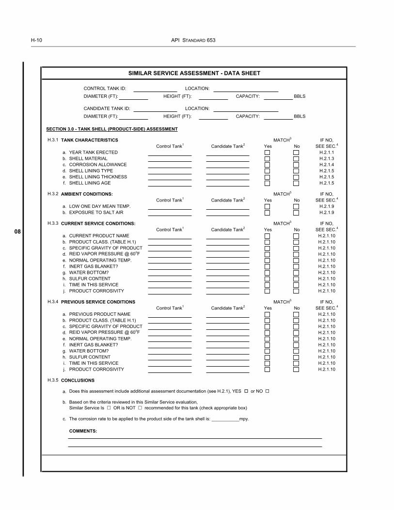
H-10 API STANDARD 653
08
For C
ommittee
Use O
nly
CONTROL TANK ID: LOCATION:
DIAMETER (FT): HEIGHT (FT): CAPACITY: BBLS
CANDIDATE TANK ID: LOCATION:
DIAMETER (FT): HEIGHT (FT): CAPACITY: BBLS
SECTION 3.0 - TANK SHELL (PRODUCT-SIDE) ASSESSMENT
H.3.1 TANK CHARACTERISTICS
a. YEAR TANK ERECTEDb. SHELL MATERIALc. CORROSION ALLOWANCEd. SHELL LINING TYPEe. SHELL LINING THICKNESSf. SHELL LINING AGE
H.3.2 AMBIENT CONDITIONS:
a. LOW ONE DAY MEAN TEMP.b. EXPOSURE TO SALT AIR
H.3.3 CURRENT SERVICE CONDITIONS:
a. CURRENT PRODUCT NAMEb. PRODUCT CLASS. (TABLE H.1)c. SPECIFIC GRAVITY OF PRODUCTd. REID VAPOR PRESSURE @ 60oFe. NORMAL OPERATING TEMP.f. INERT GAS BLANKET?g. WATER BOTTOM?h. SULFUR CONTENTi. TIME IN THIS SERVICEj. PRODUCT CORROSIVITY
H.3.4 PREVIOUS SERVICE CONDITIONS
a. PREVIOUS PRODUCT NAMEb. PRODUCT CLASS. (TABLE H.1)c. SPECIFIC GRAVITY OF PRODUCTd. REID VAPOR PRESSURE @ 60oFe. NORMAL OPERATING TEMP.f. INERT GAS BLANKET?g. WATER BOTTOM?h. SULFUR CONTENTi. TIME IN THIS SERVICEj. PRODUCT CORROSIVITY
H.3.5 CONCLUSIONS
a. Does this assessment include additional assessment documentation (see H.2.1), YES or NO
b. Based on the criteria reviewed in this Similar Service evaluation, Similar Service Is OR is NOT recommended for this tank (check appropriate box)
c. The corrosion rate to be applied to the product side of the tank shell is: ___________mpy.
COMMENTS:
H.2.1.5H.2.1.5
H.2.1.9SEE SEC.4
H.2.1.10
SEE SEC.4
H.2.1.10
MATCH3 IF NO,Control Tank1
H.2.1.5
H.2.1.1H.2.1.3H.2.1.4
SIMILAR SERVICE ASSESSMENT - DATA SHEET
H.2.1.10H.2.1.10
H.2.1.9
IF NO,
H.2.1.10H.2.1.10
Candidate Tank2 Yes No SEE SEC.4
H.2.1.10
H.2.1.10
H.2.1.10H.2.1.10
MATCH3 IF NO,Control Tank1 Candidate Tank2 Yes No SEE SEC.4
MATCH3 IF NO,Control Tank1 Candidate Tank2 Yes No
MATCH3
Yes NoControl Tank1 Candidate Tank2
H.2.1.10H.2.1.10H.2.1.10H.2.1.10H.2.1.10H.2.1.10H.2.1.10
H.2.1.10
H.2.1.10H.2.1.10

TANK INSPECTION, REPAIR, ALTERATION, AND RECONSTRUCTION H-11
08
For C
ommittee
Use O
nly
NOTE: THE DATA SHEET SHALL BE MAINTAINED IN THE RECORD FILE AS PER SEC. 6.8.
SUBMITTED BY: DATE:
APPROVED BY: DATE:
NOTES:1. The Control Tank is the tank for which service conditions and corrosion rates are well known.2. The Candidate Tank is the tank to be compared to the Control Tank to determine if similar service concepts apply.3. “Y” or “Yes” indicates that the Candidate Tank criterion essentially matches the Control Tank .4. If the Candidate Tank criterion does not match the Control Tank criterion, see H.2.1.
SIMILAR SERVICE ASSESSMENT - DATA SHEET

H-12 API STANDARD 653
08
For C
ommittee
Use O
nly
CONTROL TANK ID: LOCATION:
DIAMETER (FT): HEIGHT (FT): CAPACITY: BBLS
CANDIDATE TANK ID: LOCATION:
DIAMETER (FT): HEIGHT (FT): CAPACITY: BBLS
SECTION 4.0 - TANK SHELL (EXTERNAL SIDE) ASSESSMENT
H.4.1 TANK CHARACTERISTICS
a. YEAR TANK ERECTEDb. SHELL MATERIALc. CORROSION ALLOWANCEd. INSULATION TYPEe. INSULATION THICKNESSf. INSULATION AGEg. COATING TYPEh. COATING THICKNESSi. COATING AGE
H.4.2 AMBIENT CONDITIONS:
a. LOW ONE DAY MEAN TEMP.b. EXPOSURE TO SALT AIR
H.4.3 CURRENT OPERATING CONDITIONS:
a. PONDING/WATERb. NORMAL OPERATING TEMP.
H.4.4 PREVIOUS OPERATING CONDITIONS
a. PONDING/WATERb. NORMAL OPERATING TEMP.
H.4.5 CONCLUSIONS
a. Does this assessment include additional assessment documentation (see H.2.1), YES or NO
b. Based on the criteria reviewed in this Similar Service evaluation, Similar Service Is OR is NOT recommended for this tank (check appropriate box)
c. The corrosion rate to be applied to the ambient side of the tank shell is: ___________mpy.
COMMENTS:
NOTE: THE DATA SHEET SHALL BE MAINTAINED IN THE RECORD FILE AS PER SEC. 6.8.
ASSESSED BY: DATE:
APPROVED BY: DATE:
NOTES:1. The Control Tank is the tank for which service conditions and corrosion rates are well known.2. The Candidate Tank is the tank to be compared to the Control Tank to determine if similar service concepts apply.3. “Y” or “Yes” indicates that the Candidate Tank criterion essentially matches the Control Tank .4. If the Candidate Tank criterion does not match the Control Tank criterion, see H.2.1.
(tank owner/operator)
H.2.1.10H.2.1.10
Candidate Tank2
MATCH3 IF NO,Control Tank1 Candidate Tank2 Yes No SEE SEC.4
Yes No
MATCH3
Yes No
Yes NoControl Tank1 Candidate Tank2
Candidate Tank2
SIMILAR SERVICE ASSESSMENT - DATA SHEET
H.2.1.9
MATCH3
MATCH3 IF NO,SEE SEC.4
H.2.1.1H.2.1.3H.2.1.4
H.2.1.4
H.2.1.4H.2.1.4
IF NO,
H.2.1.4H.2.1.4
H.2.1.4
H.2.1.10
IF NO,
H.2.1.10SEE SEC.4
H.2.1.9SEE SEC.4
Control Tank1
Control Tank1

TANK INSPECTION, REPAIR, ALTERATION, AND RECONSTRUCTION H-13
08
For C
ommittee
Use O
nly
CONTROL TANK ID: LOCATION:
DIAMETER (FT): HEIGHT (FT): CAPACITY: BBLS
CANDIDATE TANK ID: LOCATION:
DIAMETER (FT): HEIGHT (FT): CAPACITY: BBLS
SECTION 5.0 - CONCLUSION SUMMARY
a. From Section 1.0, the corrosion rate to be applied to the product-side of the tank bottom is: ___________mpy.
b. From Section 2.0, the corrosion rate to be applied to the soil-side of the tank bottom is: ___________mpy.
c. From Section 3.0, the corrosion rate to be applied to the product-side of the tank shell is: ___________mpy.
d. From Section 4.0, the corrosion rate to be applied to the external side of the tank shell is: ___________mpy.
e. Based on the corrosion rates applied, the next internal inspection for this tank will be completed in Year _________.
COMMENTS:
NOTE: THE DATA SHEET SHALL BE MAINTAINED IN THE RECORD FILE AS PER SEC. 6.8.
ASSESSED BY: DATE:
APPROVED BY: DATE:(tank owner/operator)
SIMILAR SERVICE ASSESSMENT - DATA SHEET

For C
ommittee
Use O
nly

For C
ommittee
Use O
nly
S-1
APPENDIX S—AUSTENITIC STAINLESS STEEL STORAGE TANKS
S.1 ScopeS.1.1 This appendix covers the inspection, repair, alter-ation and reconstruction of stainless steel tanks that were con-structed in accordance with API Std 650, Appendix S.
S.1.2 This appendix states only the requirements that differfrom the basic rules in this standard. For requirements notstated, the basic rules must be followed.
S.2 References No changes to Section 2.
S.3 Definitions No changes to Section 3.
S.4 Suitability for ServiceS.4.1 In 4.2.4.1, the requirements of API Std 650, S.3.5shall also be satisfied.
S.4.2 In 4.2.4.3, Appendix M requirements shall be met forstainless steel tanks with design temperatures over 40ºC(100ºF) as modified by S.3.6.2 thru S.3.6.7.
S.4.3 In 4.3.3.1, the maximum allowable stress S shall bemodified as follows, for the design condition (Sd) and thehydrostatic test condition (St) the maximum allowable stressfor all shell courses shall be the lesser of 0.95Y or 0.4T.
S.4.4 Table 4-2 shall be in accordance with API Std 650,Table S-4. When the radiography schedule applied to theexisting weld is unknown, the joint efficiency of 0.7 shall beused.
S.4.5 In 4.3.3.5c, shall be changed to read “Operation attemperatures over 40ºC (100ºF)”.
S.4.6 In 4.3.3.6, the factor 2/3Y shall be replaced with 3/4Y.
S.4.7 In 4.3.4, these rules do not cover stainless steel tanks.
S.5 Brittle FractureS.5.1 The tank is suitable for continued use in ambienttemperature service
S.6 Inspection No Changes to Section 6
S.7 MaterialsS.7.1 In 7.3.1.2, add reference to ASTM A 480.
S.7.2 Structural may be built-up plate. Plate and structuralmaterial shall meet API Std 650, S.2.
S.8 Design Considerations for Reconstructed Tanks
S.8.1 In 8.4.3 the allowable stress shall be revised to meetthe allowable stresses of API Std 650, Appendix S.
S.9 Tank Repair and AlterationS.9.1 In 9.14, hot taps in stainless steel are not addressedby this appendix.
S.10 Dismantling and ReconstructionS.10.1 Welding shall also meet the requirements of APIStd 650, S.4.11
S.10.2 Thermal cutting of stainless steel shall be by theiron powder burning carbon arc or plasma-arc methods.
S.10.3 The storage requirements of API Std 650, S.4.2shall be met.
S.10.4 When specified by the purchaser the requirementsof API Std 650, S.4.5 shall be met.
S.11 WeldingS.11.1 Welding shall also meet the requirements of APIStd 650, S.4.11
S.12 Examination and TestingS.12.1 Any reference to magnetic particle method shall bereplaced with the liquid penetrant method.
S.12.2 In 12.3, the quality of test water shall meet API Std650, S.4.10
S.13 AppendicesS.13.1 Appendix F—NDE Requirements Summary anyreferences to Magnetic Particle Examination shall be disre-garded.
05
0505

For C
ommittee
Use O
nly
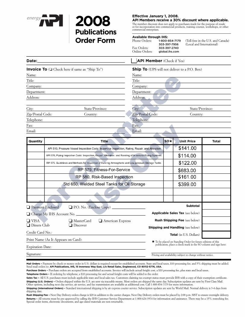
For C
ommittee
Use O
nly
Invoice To (❏ Check here if same as “Ship To”)
Name:
Title:
Company:
Department:
Address:
City: State/Province:
Zip/Postal Code: Country:
Telephone:
Fax:
Email:
❏ Payment Enclosed ❏ P.O. No. (Enclose Copy)
❏ Charge My IHS Account No.
❏ VISA ❏ MasterCard ❏ American Express❏ Diners Club ❏ Discover
Credit Card No.:
Print Name (As It Appears on Card):
Expiration Date:
Signature:
Quantity Title Total
Subtotal
Applicable Sales Tax (see below)
Rush Shipping Fee (see below)
Shipping and Handling (see below)
Total (in U.S. Dollars)
★ To be placed on Standing Order for future editions of this publication, place a check mark in the SO column and sign here:
Pricing and availability subject to change without notice.
Date:
SO★ Unit Price
❏ API Member (Check if Yes)
Ship To (UPS will not deliver to a P.O. Box)
Name:
Title:
Company:
Department:
Address:
City: State/Province:
Zip/Postal Code: Country:
Telephone:
Fax:
Email:
Mail Orders – Payment by check or money order in U.S. dollars is required except for established accounts. State and local taxes, $10 processing fee, and 5% shipping must be added.Send mail orders to: API Publications, IHS, 15 Inverness Way East, c/o Retail Sales, Englewood, CO 80112-5776, USA.
Purchase Orders – Purchase orders are accepted from established accounts. Invoice will include actual freight cost, a $10 processing fee, plus state and local taxes.Telephone Orders – If ordering by telephone, a $10 processing fee and actual freight costs will be added to the order.Sales Tax – All U.S. purchases must include applicable state and local sales tax. Customers claiming tax-exempt status must provide IHS with a copy of their exemption certificate.Shipping (U.S. Orders) – Orders shipped within the U.S. are sent via traceable means. Most orders are shipped the same day. Subscription updates are sent by First-Class Mail. Other options, including next-day service, air service, and fax transmission are available at additional cost. Call 1-800-854-7179 for more information.Shipping (International Orders) – Standard international shipping is by air express courier service. Subscription updates are sent by World Mail. Normal delivery is 3-4 days fromshipping date.Rush Shipping Fee – Next Day Delivery orders charge is $20 in addition to the carrier charges. Next Day Delivery orders must be placed by 2:00 p.m. MST to ensure overnight delivery.Returns – All returns must be pre-approved by calling the IHS Customer Service Department at 1-800-624-3974 for information and assistance. There may be a 15% restocking fee.Special order items, electronic documents, and age-dated materials are non-returnable.
Effective January 1, 2008.API Members receive a 30% discount where applicable.The member discount does not apply to purchases made for the purpose of resale or for incorporation into commercial products, training courses, workshops, or othercommercial enterprises.
Available through IHS:Phone Orders: 1-800-854-7179 (Toll-free in the U.S. and Canada)
303-397-7956 (Local and International)Fax Orders: 303-397-2740Online Orders: global.ihs.com
2008 PublicationsOrder Form

For C
ommittee
Use O
nly
API provides additional resources and programs to the oil and natural gas industry which arebased on API Standards. For more information, contact:
API MONOGRAM® LICENSINGPROGRAMPhone: 202-962-4791Fax: 202-682-8070Email: [email protected]
API QUALITY REGISTRAR(APIQR®)> ISO 9001 Registration> ISO/TS 29001 Registration> ISO 14001 Registration> API Spec Q1® RegistrationPhone: 202-962-4791Fax: 202-682-8070Email: [email protected]
API PERFORATOR DESIGNREGISTRATION PROGRAMPhone: 202-682-8490Fax: 202-682-8070Email: [email protected]
API TRAINING PROVIDERCERTIFICATION PROGRAM(API TPCPTM)Phone: 202-682-8490Fax: 202-682-8070Email: [email protected]
API INDIVIDUAL CERTIFICATIONPROGRAMS (ICP®)Phone: 202-682-8064Fax: 202-682-8348Email: [email protected]
API ENGINE OIL LICENSING ANDCERTIFICATION SYSTEM (EOLCS)Phone: 202-682-8516Fax: 202-962-4739Email: [email protected]
API PETROTEAM (TRAINING,EDUCATION AND MEETINGS)Phone: 202-682-8195Fax: 202-682-8222Email: [email protected]
API UNIVERSITYTM
Phone: 202-682-8195Fax: 202-682-8222Email: [email protected]
Check out the API Publications, Programs,and Services Catalog online at www.api.org.
Copyright 2008 – API, all rights reserved. API, API monogram, APIQR, API Spec Q1,API TPCP, ICP, API University and the API logo are either trademarks or registeredtrademarks of API in the United States and/or other countries.
THERE’S MOREWHERE THIS CAME FROM.

For C
ommittee
Use O
nly

For C
ommittee
Use O
nly
Product No. C65303