tank guide - components - tankspan leasing ltd
TRANSCRIPT

History of the ISO Container
The standard box container was developed in the mid 50’s by
the Americans, in a move to use the container as the ‘outer
packaging to the then traditional cargo sling methods of
unloading the contents from a lorry, into a ship, and then into
another lorry for final delivery. The concept ‘did away’ with
the wheels and the manpower, and improved the storage and
handling methods - an altogether more flexible mode of carriage.
By the early 60’s the container dimensions had standardised to
an international standard size of 20’ long, 8’ wide and 8’6” high
- the ISO (international Standards Organisation) Frame. At each
corner of the container is fitted with a corner casting, which
allows for the container to sit on a chassis, a railcar, in a ships
cel guide or be handled by a spreader. To prevent movement,
a twistlock twist into the corner casting, locking it in position.
By the mid 60’s the first tank Containers were being built - a
cylindrical vessel set within the ISO frame.
The ISO Tank Container was developed for the carriage of all
types of liquids, ranging from, but not limited to, portable (food
grade) liquids, non hazardous, and hazardous liquids, including
corrosives, flammables, toxics, and explosives. The Tank
Container eliminates the risks in transferring liquids from one
vessel to another, and provides for an extremely safe, secure,
cost effective, and viable mode of transportation. Once the Tank
Container has discharged, it is taken to a recognized cleaning
station, cleaned thoroughly for that product, and then made
ready for it’s next load.
Components
Tankspan Leasing Ltd
Email: [email protected] Web: www.tankspan.com
Tank Guide - Components
������� ����
��� ���������������
��������
����� ��� ����� ����������� � ����� ������� ��� ������
��������������������� ������
�������� �������������� ����� ������ ����
��� ��������� � ��� � ��� ���
������ �������� ������� ��������� ��������� ��������� �������� ������ ���� �����
���������� ������� ���
���������� �������
������ ������
����� �������
�����������
���� �����
������ ������
Tel: +44 (0) 1483 425900The Old Farm Office, Peper Harow, Godalming, Surrey, UK
Tankspan Leasing Ltd
Email: [email protected] Web: www.tankspan.com
Components – Tank Fitments
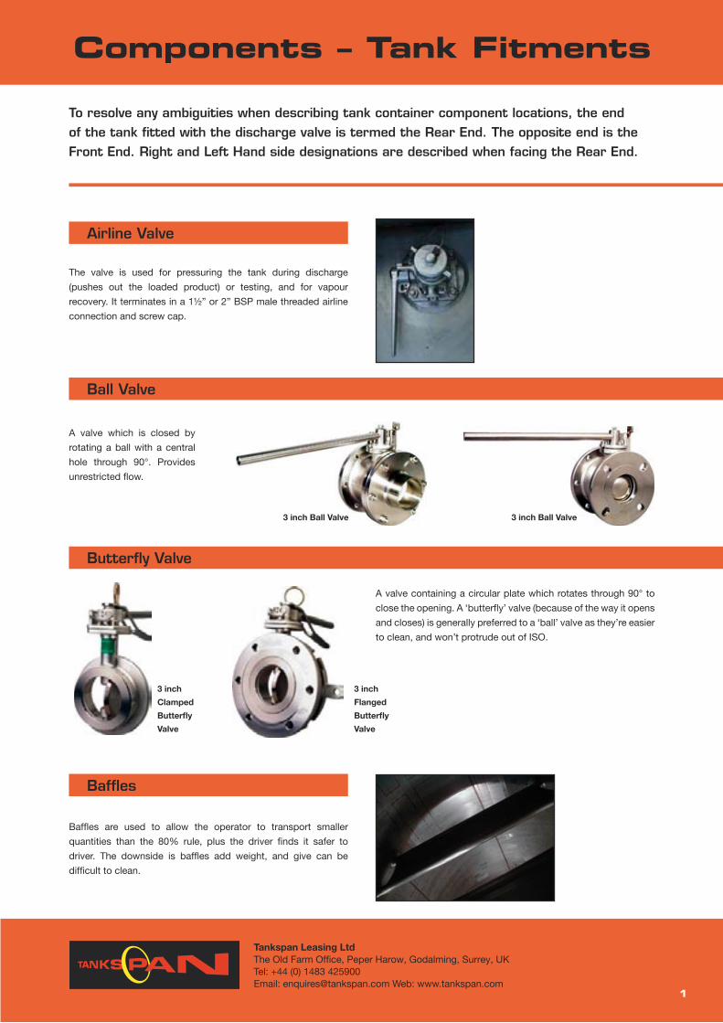
Airline Valve
The valve is used for pressuring the tank during discharge
(pushes out the loaded product) or testing, and for vapour
recovery. It terminates in a 11⁄2” or 2” BSP male threaded airline
connection and screw cap.
To resolve any ambiguities when describing tank container component locations, the end of the tank fitted with the discharge valve is termed the Rear End. The opposite end is the Front End. Right and Left Hand side designations are described when facing the Rear End.
Components – Tank Fitments
1
Ball Valve
A valve which is closed by
rotating a ball with a central
hole through 90°. Provides
unrestricted flow.
Butterfly Valve
A valve containing a circular plate which rotates through 90° to
close the opening. A ‘butterfly’ valve (because of the way it opens
and closes) is generally preferred to a ‘ball’ valve as they’re easier
to clean, and won’t protrude out of ISO.
3 inch Ball Valve 3 inch Ball Valve
3 inch
Clamped
Butterfly
Valve
3 inch
Flanged
Butterfly
Valve
Baffles
Baffles are used to allow the operator to transport smaller
quantities than the 80% rule, plus the driver finds it safer to
driver. The downside is baffles add weight, and give can be
difficult to clean.
The Old Farm Office, Peper Harow, Godalming, Surrey, UKTel: +44 (0) 1483 425900

Tankspan Leasing Ltd
Email: [email protected] Web: www.tankspan.com
Components – Tank Fitments
2
Bursting Disc / Rupture Disc / Frangible Disc
A thin membrane made of a suitable material such as S/S of
teflon (PTFE) which has a known tolerance to pressure. It has
two functions one to protect the valve from corrosion, (especially
in the case of highly corrosive materials) & secondly a pressure
relief device which breaks when the pressure exceeds the
pressure set. The Bursting Disk is set between the MAWP and
the Test Pressure. For a Standard Tank (see separate section)
the MAWP is 4 BAR. e.g. Bursting Disk set at 4.84 BAR. Used
for emergency relief or used as a hermetic seal for relief valves
to prevent the release of toxic or especially hazardous vapours.
When it is in series it sits under the Relief Valve, and looks like
an egg poacher / frying pan. However some products, such as
Hydrogen Peroxide the bursting disc is in parallel – a separate
hole next to the PV. It also requires a venting system with a
special relief capacity (more than most).
Bottom Outlet
IMO 1 tanks normally have a bottom outlet similar to that fitted
to the IMO 2 but the outlet is flanged and drilled for bolting in
accordance with British Standard table ‘D’ and closed with
a stainless steel blanking plate. However, bottom outlets are
prohibited with certain high hazard cargoes.
Bottom Valve Assembly
Customs Sealing
Facilities for customs sealing are provided in accordance with the
requirements of the Customs Convention on Containers.
Permanent sealing consists of approved rivets, welded bars
or bolts. Temporary seals at cargo access points are fitted by
customs officers using the approved locking devices.
The permanent sealing method used should be noted before
removing or stripping any fittings. The approved permanent
welded sealing bars or TIR/wires should always be replaced if
damaged or after maintenance is completed.
The Old Farm Office, Peper Harow, Godalming, Surrey, UKTel: +44 (0) 1483 425900

Tankspan Leasing Ltd
Email: [email protected] Web: www.tankspan.com
Components – Tank Fitments
3
Cladding
Cladding – GRP (FRP) – Glass reinforced plastic (Fibre reinforced
polyester) resin sheet with glass fibre used to encase insulation.
The cladding jacket is to protect the insulation against rain / sea
water.
GRP or Aluminium?
From a cosmetic point plain aluminium looks dreadful, within 6
months it’s oxidised, and looks dull and distinctly shabby. White
aluminium looks better than plain. Plain aluminium corrodes
much faster than white aluminium. Small cracks / holes can have
drastic consequences: increase in weight, the water will stop
keeping it insulates, sagging, and possible corrosion - seawater
- chlorine = corrosive. Water finding it’s way through a split
cladding could take 6 months before it comes out of the bottom
of the tank. There have been such cases where they thought the
tank was leaking.
The salt in seawater initially corrodes in the bottom panels, and
then the side panels. Corrosion takes place from the inside, as
well as the outside. Corrosion will become apparent within 5-7
years. Our preference is GRP finished in white, even though it’s
generally more expensive than aluminium, but in the long term it
becomes cheaper, and its benefits become more apparent. With
GRP you wouldn’t have patching problems, you wouldn’t have
creases, you wouldn’t have dents, you wouldn’t have bumps. It
looks good aswell.
Cladding Aluminium Sides
Cladding AluminiumCladding
Data / CSC Plate
The tanks passport. A plate that identifies the owner / manager
of the tank, the unique serial number, the date of manufacture, as
well as indicating significant data and recording the test period
validity. (See web for image.)
Discharge Valves
Discharge Valves – usually have 3 shut off devices. IMO 1 and
IMO 2 tanks have a double valve system consisting of an internal
stainless steel foot valve, (also known as a emergency valve)
operated by an external
handle biased-closed
by a spring, plus a 3”
butterfly valve with a 3”
BSP screwed outlet and
a blanking cap.
Dip Stick / Tube
A calibrated bar situated in the manhole that is used to measure
the amount of liquid in the tank. A measurement is taken off the
bar, and then cross referenced with the calibration chart (see an
example in “Samples”. This can only be used with non hazardous
products.
The Old Farm Office, Peper Harow, Godalming, Surrey, UKTel: +44 (0) 1483 425900

Tankspan Leasing Ltd
Email: [email protected] Web: www.tankspan.com
Components – Tank Fitments
4
Document Holder A sealed tube for carrying documents, such as the transport
action, cleaning certificate, etc.
Earth Point
A Connection for attaching an earthing strap. This should be
made of a non corrodible, good conducting metal, be left bare,
and be in direct contact with the tank shell. In some cases it
is fitted to lower rear frame cross-member, which is directly
Earth
Lead
Flame Trap
A metal gauze, which
is used when carrying
flammable liquids. It
permits pressure to be
expelled, but prevents
flashback.
Flame Gauze
There are two basic tank container frame designs - the full frame
and the beam frame. Both types fully meet the requirements of
ISO regulations and are used for identical purposes. On each
corner there is a hole to allow for a twist lock to secure the tank
to the chassis / spreader / ships cellular guide.
The FULL FRAME (box type) supports the tank within a steel
framework with continuous side rails.
Frames
The BEAM FRAME The BEAM Tank has been developed by
some manufacturers whereupon the frame ends are welded
into the shell giving inherent
strength, but with no top or
bottom rails. The beam tank
has a lower tare weight due to
its construction, and is thereby
able to carry a higher payload.
connected to the shell. Ensure that the earth connection is made
from the tank earthing point to a local earth position, before
making connections.
Earth
Lead
The Old Farm Office, Peper Harow, Godalming, Surrey, UKTel: +44 (0) 1483 425900

Tankspan Leasing Ltd
Email: [email protected] Web: www.tankspan.com
Components – Tank Fitments
5
Fusible LinkA fusible Link has been designed to melt in the event of a fire,
thereby closing the foot valve without any human intervention.
The U.S. DoT proposes to enforce the fitting of this device to all
IM portable tanks transporting flammable, pyrophoric, oxidizing
or toxic cargoes on a transport vehicle with the power unit
attached. The system has to be fitted to all tanks by October
1st 2003.
The kit comprises of 2 brackets, which are welded to the tank,
between which a spring and fusible element are fastened. A
cable then links the spring to the existing remote closure system.
Should a fire melt the fusible element, the spring is allowed to pull
the remote closure cable and close the foot valve.
Fusible Link Assembly
Gaskets
PTFE Polytetrafluoroethylene.
A plastic used for gaskets
and bearings. It has a wide
temperature tolerance and is
resistant to most chemicals.
SWR Sweet White Rubber.
A rubber used for Food grade
products.
Collapsible hand rails cover the full length of the tank container,
which allows for safe access. There is increasing pressure for
operators to use tanks with hand rails, especially in Europe, but
as a tank could go anywhere in the world, there is a chance of
damage, being out of ISO, or stolen. Both operators and lessors
Hand Rail
Heating - Electric Continue Overleaf
The external shell heating systems consist of a network of
elements in contact with the shell over the bottom third of the
circumference of the tank. These heaters are especially suitable
for heat sensitive products. This system operates on either 200-
280 V 3-phrase or 340-480 3 phase. Power output at 440 V is
15kW.
Note: That in principle, electric heating is designed to maintain
temperature only. It is not designed to reheat the product.
are reluctant to invest in them, as
chemical companies won’t pay a
premium for them. However it is an
essential piece of equipment on the
European Swap Body.
Viton A
A synthetic rubber used for gaskets.
Has good sealing properties and
is tolerant to a wide spectrum of
chemicals.
Standard seal and gasket materials
vary according to the tank type. The
operation must ensure that the seals
are compatible with the product to be
carried.
The Old Farm Office, Peper Harow, Godalming, Surrey, UKTel: +44 (0) 1483 425900

Tankspan Leasing Ltd
Email: [email protected] Web: www.tankspan.com
Components – Tank Fitments
Heating - Electric ...Continued
Control Box
The electrical controls are mounted on the frame at the rear of
the tank container.
The control box or boxes contain the following equipment:
• Fuses or circuit breakers
• Temperature controls to Limit the maximum and minimum
cargo
• Temperature
• Main switch to isolate the unit from the power supply
Reefer - Standard Electric Plug
All electric tanks should be equipped with a 4 pin plug (3 pins
phase and 1 big pin earth) in the following way:
�� �� �� ��
��� � ��� �
Control Box
Elecrical Unit
Heating - Steam
Steam Heating is the most efficient means of heating the tank
cargo. Typical heating area – 8 sq.m. The steam channels,
continuous loops of pipework, usually on the outside of the lower
half of the tank, terminate at the rear of the tank and are closed
by threaded dust caps. The inlet and outlet can be fitted with a
valve, and the outlet should be fitted with a steam condensate
trap. Care should be taken to ensure the maximum working
pressure of the system is indicated on the date plate.
Insulation
Standard thickness is 50mm. Examples: Polyurethane foam
(greenish), or Rockwell, similar to loft insulation, or Fibreglass.
Rockwell is better for high temperature products. Foam crumbles
away at about 1100C -
1150C.
This insulation may degrade
at excessive temperature.
Before loading check that
the loading and operating
6
temperature do not
exceed the maximum
permissible operating
temperature marked on
the data plate.
32 Amps CEE 17
How to check to see if you have the correct plug. Look at the
pins of plug, with the ’nose’ of plug in the 6 o´clock position, the
big pin (earth) should be in 9 o´clock position.
View on socket for a.m. plug:
Elecrical Unit Connections
The Old Farm Office, Peper Harow, Godalming, Surrey, UKTel: +44 (0) 1483 425900

Tankspan Leasing Ltd
Email: [email protected] Web: www.tankspan.com
Components – Tank Fitments
Labelling
These identify the product inside the tank. They have to be
precise and must conform to all the relevant regulations,
wherever the tank travels.
Note: All odd labels must be removed prior to loading, to save
confusion / potential accidents happening.
Manlid
The manlid has to be the same pressure as the tank, and allow
enough space for a person to enter the tank. The manlid is held
down with a minimum of six swing bolts, the wing nuts are of a
softer metal, otherwise they could weld together when tightened.
Our tanks have a 500mm diameter manlid with eight swing bolts.
A gasket is fitted between the tank and the manlid.
A ‘safe bolt’ may be fitted to the manlid as a safety precaution
against opening, e.g. when the tank is under pressure.
Manometer / Pressure Gauge
A Manometer / Pressure Gauge is fitted to the airline connection,
and can be fitted during filling, discharging or testing.
7
Manlid Manlid food Grade MVC-032
The Old Farm Office, Peper Harow, Godalming, Surrey, UKTel: +44 (0) 1483 425900

Tankspan Leasing LtdSuite 5, 50 Churchill Square, Kings Hill, West Malling, Kent ME19 4YUTel: +44 (0) 1732 229 800 Fax: +44 (0) 1732 522 992Email: [email protected] Web: www.tankspan.com
Components – Tank Fitments
Placard Boards
Placard Boards are used for putting on
current labels
Labels are fairly difficult to remove from
the cladding, and look very messy - thus
the reason for using a placard board.
Pressure / Vacuum Safety Relief Valve (PV)
A combined pressure vacuum relief valve to protect the tank
against excessive overpressure and or vacuum. How many are
used is dependant upon the product. The usual for a standard
tank is to have just one Maxi-
flow (a combined pre-vac valve).
When pressure builds up, the
PV springs open to prevent the
tank blowing up. It will allow air
into the tank to stop it crushing
inwards. The PV is set between
the MAWP and Test Pressure.
Remote Control
Remote Control on the side of
the tank, allows the driver to
close off the discharge valve
from this safe location.
Shell
IMO 1’s are made of stainless steel (currently 316L – low in
carbon 1.4401 to DIN 17441, older tanks were sometimes made
of 316TI - Titanium) and approximately 4.6 – 4.8mm thick. IMO 5
Gas Tanks are usually made from carbon steel.
8
Remote Control for Bottom Asembly
Remote Control for Bottom Outlet

Tankspan Leasing Ltd
Email: [email protected] Web: www.tankspan.com
Components – Tank Fitments
Spill Boxes
2 Stainless steel boxes fitted around manlid / relief valve and around top discharge / air inlet. 25mm PVC external drainage tubes fitted.
Steam Trap / Relief Valve
Thermodynamic steam trap, situated on the outlet which
automatically sensors condensate and utilises the pressure
of the steam to eject the condensate from the system thus
maintaining optimum heating characteristics.
Stem Relief Valve
When the steam cools down, the steam relief valve opens, only
permitting water to pass. The remaining steam is condensed,
ensuring live hot steam continually replaces the cooled down
steam.
Syphon Pipe
A tube from the top outlet to the bottom of the tank, which
allows liquid to be discharged through the top outlet by means of
pressure or suction.
Syphon Tube Syphon Tube Top Syphon Tube Bottom
Tank Number
Tank Number has a four letter prefix, followed by six numbers and
then a check digit. (See ‘check digit programme’ SG calculator).
If all other information is missing from the container, the owner
can still be identified by the prefix, by checking this in the code
book produced by BIC of Paris (see useful links).
9
The Old Farm Office, Peper Harow, Godalming, Surrey, UKTel: +44 (0) 1483 425900

Tankspan Leasing Ltd
Email: [email protected] Web: www.tankspan.com
Components – Tank Fitments
Temperature Gauge / Thermometer will only give the temperature
of the product in that location. A digital gauge is superior to a
thermometer, better sealed, but more expensive. The stainless
steel surround is generally made of a different quality (not 316)
and seawater will eventually destroy it, as seawater is dilute
hydrochloric acid!
Temperature Gauge / Thermometer
��������� ������
������� ������
����
����
Thermometer
A thermometer, indicating the cargo temperature, is
fitted on all electrically heated tanks. The majority
of steam heated tanks have facilities for fitting a
thermometer if required.
The thermometer sensor
is either immersion or
surface type, connected
to a dial.
Top Outlet
The top outlet is situated at the rear of the tank and consists of
a syphon pipe, a 3 inch plate valve or butterfly valve, a 3 inch BS
table ‘D’ flange and a blanking plate.
NOTE: Top outlet loading/discharge is not commonly used, so to
avoid unnecessary maintenance and cleaning, the syphon pipe
and valve may be supplied on IMO 1 tanks only when specifically
requested.
10
Top Discharge Assembly
The Old Farm Office, Peper Harow, Godalming, Surrey, UKTel: +44 (0) 1483 425900

Tankspan Leasing Ltd
Email: [email protected] Web: www.tankspan.com
Components – Tank Fitments
11
Tank Markings
Walkway
A ladder and anti-slip walkway are provided for easy and safe
access to top fittings and top corner castings. To reduce the
overall weight of the tank, walkways (these days) do not run
the whole length of the tank, as it is only necessary to reach the
components.
Owners code and serial number
Country codeSize of containerPressure rating of vessel
Max designed payload
Max gross designed weight
Max gross weight permitted on European railways
Weight of empty container
ISO Max gross weight
Care should be taken not to walk directly on the tank, as this
could be very dangerous, plus it avoids damage to the cladding
and insulation.
International (european) railway approval and country of registration
Container height marking
Compliance with US DOT (CFR 49)
Compliance with RID requirements
The Old Farm Office, Peper Harow, Godalming, Surrey, UKTel: +44 (0) 1483 425900