tan 23- non-destructive investigation of standing structures
DESCRIPTION
Advice and information on the range of non-destructive investigative and recording techniques available for examining historic fabric.TRANSCRIPT
H r m ~ l c S C ~ T L A N ~ TECHNICAL ~ C E NOTES 1 Preparation and use of Lime Mortars (revised 1995)
2 Conservation of Plasterwork (1994)
3 Performance Standards for Timber Sash and Case Windows (1994)
4 Thatch & Thatching Techniques (1996) A guide to conserving Scottish thatching traditions
5 The Hebridean Blackhouse (1996) A guide to materials, construction and maintenance
6 Earth Structures and Construction in Scotland (1996) A guide to the Recognition and Conservation of Earth Technology in Scottish Buildings
7 Access to the Built Heritage (1996) Advice on the provision of access for people with disabilities to historic sites open to the public
8 Historic Scotland Guide to International Conservation Charters (1997)
9 Stonecleaning of Granite Buildings (1997)
10 Biological Growths on Sandstone Buildings (1997) Control and Treatment
11 Fire Protection Measures in Scottish Historic Buildings (1997)
12 Quarries of Scotland (1997) An illustrated guide to Scottish geology and stone working methods based on the British Geological Survey Photographic Archive of selected building stone quanies
13 The Archaeology of Scottish Thatch (1998)
14 The Installation of Sprinkler Systems in Historic Buildings (1998)
15 Lime Harling and Rendering (2000)
16 Burrowing Animals and Archaeology (1999)
17 Bracken and Archaeology (1999)
18 The Treatment of Graffiti on Historic Surfaces (1999)
19 Scottish Aggregates for Building Conservation (1999)
20 Corrosion in Masonry Clad Early 20th Century Steel Framed Buildings (2000)
21 Scottish Slate Quarries (2000)
22 Fire Risk Management in Heritage Buildings (2001)
GUIDES FOR PRACTITIONERS
Stone Cleaning - A Guide for Practitioners (1994) Timber Decay in Buildings - The Conservation Approach to Treatment (1999) 1 Rural Buildings of the Lothians: Conservation and Conversion (1999) 2 Conservation of Historic Graveyards (2001)
Available from:
Historic Scotland Technical Conservation, Research and Education Division Scottish Conservation Bureau Longmore House Salisbury Place EDINBURGH EH9 1SH Tel 0131 6688668 Fax 0131 668 8669 email [email protected]
by GBG (G B Geotechnia Ltd)
Published by Historic Scotland
ISBN 1900168 98 7 O Crown Copyright
Edinburgh 2001
Commissioned by
TECHNICAL CONSERVATION, RESEARCH AND
EDUCATION DMSION

ACKNOWLEDGEMENTS The staff of GBG who were involved in the writing of this advice note wish to thank Historic Scotland for their patience, encouragement and assistance throughout the project. We wos~ld also like to thank conservators and the owners of historic buildings and monuments across Scotland, England, Wales and Ireland and building professionals around the world who have encouraged the development of non-destructive investigative and recording techniques. The authors gratefully acknowledge the skilful editing and support of the Technical Conservation, Research and Education Division of Historic Scotland, particsrlarly Robin Kent, Una Lee and Audrey Dakin.

CONTENTS
FOREWORD v 4 NUCLEAR METHODS 29
LIST OF ABBREVATIONS vi 4.1 Radiography 29
SUMMARY 1 4.1.1 Applications of Radiography 29
FREQUENCY OF VARIOUS NON- DESTRUCTIVE INVESTIGATION TECHNIQUES 2
1 INTRODUCTION 3
2 NON-DESTRUCTIVE INVESTIGATION METHODS 5
2.1 Introduction 5
2.2 Non-Destructive Testing 5
2.3 Quality and Reliability 6
2.4 Limitations 8
2.5 Licensing and Other Legislative Considerations 8
ELECTRO-MAGNETIC METHODS
Impulse Radar
Applications of Impulse Radar
Theory and Limitations of Impulse Radar
Equipment
Impulse Radar Surveys
Thermography
Applications of Thermography
Theory and Limitations of Thermography
Thermographic Survey Equipment
Thermographic Surveys
Metal Detection
Uses for Metal Detectors
Theory and Limitations of Metal Detectors
Equipment
Metal Detector Surveys
Free Electro-Magnetic Radiation (FEMR)
Applications of FEMR
Theory and Limitations of Radiography
Equipment
Radiographic Surveys
ACOUSTIC METHODS
Introduction to Acoustics
Ultrasonic Pulse Velocity Measurement (UPV)
Applications of UPV
Theory and Limitations of UPV
Equipment
UPV Surveys
Impact-Echo 3 8
Applications of Impact-Echo 3 8
Theory and Limitations of Impact-Echo 38
Impact-Echo Equipment 40
Impact-Echo Surveys 40
PLANNING AN INVESTIGATION 41
Preparing for a Non-Destructive Investigation 4 1
Timing the Investigation 4 1
Defining the Scope of the Investigation 41
Estimating Budgets for An Investigation 42
Selecting the Investigator 43
Elements required in a Quotation for Work 43
During and After the Investigation 44
Access Considerations 44
Health & Safety 47
Analysis and Reporting 48
CASE STUDY: KILDRUMMY CASTLE 49
3.4.2 Theory and Limitations of FEMR 24 8 BIBLIOGRAPHY 5 1 3.4.3 Equipment 26 9 GLOSSARY 52 3.4.4 FEMR Surveys 26 10 USEFUL ADDRESSES 55

TAN 23 NON-DESTRUCTIVE INVESTIGATION OF STANDING STRUCTURES
LIST OF ILLUSTRATIONS
Plates 4. Effect of building materials, thickness, arrangement and defects on heat flow (illustrative
1. Impulse radar investigation of a masonry arch only).
bridge in progress. Access to the soffit by hydraulic cradle. 5. Metal Detection using magnetic reluctance
method. 2. Typical impulse radar equipment (analogue)
- -
6. Metal Detection using electrical conductivity 3. Impulse Radar survey in progress to locate
method suspended stone flags in cathedral floor.
7. Sample of results from a combined metal detector 4. Sample image from a thermographic survey of
and impulse radar investigation the interior of a historic building. The change in construction materials behind existing mouldings 8. Examples of applications of FEMR techniques and finishes shows clearly as a lighter area. (active and passive)
5. Thermographic inspection in progress. Hand held 9. Specimen results from an investigation to track camera is panned across the wall and the results flues in a party wall using a variety of techiniques viewed as an image on the trolley mounted including FEMR processor. Power is supplied as an unspillable
10. Relationship between acoustic pulse velocity and (gel type) 12v car battery.
compressive strength of concrete 6. Metal detectors being used to locate metal ties in
11. UPV in operation on a face bedded sandstone a masonry wall. A larger 'ground' metal detector
block stands against the wall.
12. Basic theory of impact-echo method 7. FEMR methods being used to trace an iron drain
pipe behind a wall 13. Elevation of chapel gable (north-east wall), Kildmmmy Castle
8. Portable radioactive source (Cobalt 60) 14(a)(b) Specimen results from a non-destructive
9. Typical UPV survey in operation (indirect investigation of Kildrummy Castle walls
arrangement) (structure and condition) 10. Equipment used for impact-echo method
11. Facade inspection being carried out from an Tables hydraulic hoist, Old St. Andrews House, 1. Typical penetration, resolution and uses of Edinburgh different frequency impulse radar transmitters
12. Aerial view of Kildmmmy Castle
13. Repair works at Kildmmmy Castle in the early twentieth century
Figures
1. Basic theory of impulse radar collecting data from a rubble filled masonry wall.
2. Sample of impulse radar data recovered and the drawings generated from it during an investigation to locate underfloor chambers
2. Effect of magnetic and conductive material properties on detection with metal detectors
3. Typical ultrasonic pulse velocities for some common building materials
4. Typical distribution of fees and expenses across the three phases of an investigation
5. Typical investigations, techniques and associated site works
6. System for scoring proposals
3. Three different factors affecting apparent surface temperature of a stone wall.

TAN 23 NON-DESTRUCTIVE INVESTIGATION OF STANDING STRUCTURES
FOREWORD
Minimum intervention has for many years been a key tenet of conservation philosophy. The Stirling Charter: Conserving Scotland's Built Heritage, published by Historic Scotland in January 2000, re-states its importance. The publication of this Technical Advice Note is therefore particuarly relevant and timely.
For sometime many have been aware of the potential usefulness of non-destructive investigation techniques in the conservation of standing structures. An investigation of part of Kildrummy Castle, where concerns had been raised regarding the structural effectiveness of the wall core, was undertaken as a pilot project in 1995. Kildrummy is a ruined thirteenth century castle and a Scheduled Ancient Monument in Historic Scotland care. Traditional methods of assessing the extent and seriousness of decay in the wallcore might have included core-boring or downtaking sections of wall. However, in view of the significance of the fabric, an impulse radar survey was commissioned to allow a more focussed understanding of site conditions.
The results from this work were used to inform future conservation work at the monument and also to shape the development of and provide illustrative material for this note.
This Technical Advice Note covers electro-magnetic (including impulse radar, thermography, metal detection and free electro-magnetic radiation) nuclear and acoustic test methods for use on standing structures. Factors that should be taken into account when planning a non-destructive investigation are also covered. Given the topic being addressed, the language used is, inevitably, more scientific than technical. However, considerable effort has been taken to try to 'translate' the information in such a way that practitioners will find the text helpful and informative.
The guidance provided is not intended to be prescriptive or to be used as a specification for works on site. Instead, this note is intended to act as a primer. The intention is to arm the conservation professional with an understanding of the capabilities and limitations of the various techniques available. This should allow an informed decision to be made on the appropriateness of each technique in any particular situation.
Ingval Maxwell Director TCRE September 2001

TAN 23 NON-DESTRUCTIVE INVESTIGATION OF STANDING STRUCTURES
LIST OF ABBREVIATIONS
Abbreviations used in this document
CAD Computer aided design
DAT Digital Audio Tape
FEMR Free ElectroMagnetic Radiation
GPR Ground Probing RADAR
HSE Health and Safety Executive
NAMAS National Analytic and Accreditation Service
PUNDIT Pulsed Ultrasonic Non-Destructive Inspection and Testing
ST Units used in this document
G gigs
Hz hertz
k Kilo
M mega
m milli
CL micro
S seconds
v volt
RADAR Radio Detection And Ranging
SONAR Analogy with 'RADAR' using sonic pulses
UKAS United Kingdom Accreditation Service
UPV Ultrasonic Pulse Velocity

TAN 23 NON-DESTRUCTIVE INVESTIGATION OF STANDING STRUCTURES
SUMMARY
The conservation of our architectural heritage has moved from a practical restorative craft to a multi- disciplinary professional team effort. Well intentioned repairs and modifications by previous conservators have all too often resulted in more rapid deterioration of ancient monuments and buildings. Our duty now is to ensure that every effort is made to arrest deterioration of historic fabric. This must apply not only to the visible exterior, but also to the hidden interior of structures and buildings.
This Technical Advice Note is concerned with structural investigation using instrumental (not analytical) methods that allow us to inspect and monitor the hidden internal structure without the need for invasive or destructive inspection. These methods facilitate the recording of easily accessed information that can inform the future maintenance and conservation of the structure.
Rapid developments in electronics, instrumentation and data acquisition technology during the latter half of the twentieth century have provided a wealth of new methods of recording and evaluating the built heritage in a non-invasive manner, such that there is much less need for 'opening up' to discover the condition and arrangement of structural materials. At the same time this has generated an enormous volume of information which can all too easily become lost or inaccessible.
The information recovered by a non-destructive investigation is factual, but requires interpretation before it can be used by conservation professionals. Records should be kept of both raw data and the interpretation put on that data at the time of collection to ensure that the reasoning behind any decisions is understood by succeeding conservation professionals.
A number of specialist non-destructive testing companies now exist with the aim of bringing these novel instrumental methods into the field of civil and structural engineering, making them available to conservation professionals. There is however a wide range of of non-destructive investigation methods available, the majority of which are probably unknown to, or generally poorly understood by, architects, engineers and others.
The prime objective of a non-destructive investigation is to provide the conservation professional with all the information required to allow appropriate and valid decisions to be made concerning the conservation of the structure. All investigative methods used should respect the historic fabric of the building and, as far as is possible, avoid interference with or destruction of any element of the historic structure. This imposes a different set of controls on the structural investigator from those hetshe normally encounters, and there is always a requirement for a very careful and well considered approach to the way in which the structure is investigated and recorded. The context of an historic building frequently forces the most effective instrument to be set aside in favour of an approach which does not disturb some element of the structure or its contents.
The benefits of non-destructive methods of investigation are clear and, with good planning, they can often provide a much more rapid and cost-effective method of gathering information than the more traditional destructive alternatives.
It is hoped that this Technical Advice Note will foster improved understanding of the range of non- destructive investigative and recording techniques available, and it attempts to identify the most appropriate applications for each. It provides information on the theory behind each technique, its capabilities and limitations, and describes the nature and quality of the results which can be expected. General guidance is offered on the application of each method within conservation projects.
It is not the intention of this document to act as a complete reference work for each of the techniques discussed, but specifically to provide sufficient information to enable a conservation professional to decide upon the methods of investigation or recording which might be most applicable in a particular situation and to direct him or her to the most appropriate specialist from whom further advice and information can be obtained.

TAN 23 NON-DESTRUCTIVE INVESTIGATION OF STANDING STRUCTURES
FREQUENCY OF VARIOUS NON-DESTRUCTIVE INVESTIGATION TECHNIQUES
The following diagram shows the approximate frequencies of the different wave forms discussed in this Advice Note. Mechanical and electro-magnetic waves are included.
Method Wave Form
r - - - " - . - - - -
r Gamma
Frequency (Hz)
Radiography
X-rays
R 0 Y G B I V j Visible
Thermography Far infra-red " - - - a
t
RADAR Micro-waves
Radio (VHF) .-
UPV Ultra-sound
Impact-echo
FEMR
Audio-sound
1 X 10⁸
1 X 10⁷
1 X 10⁴
Radio
Bands
1 X 10'
pp
TAN 23 NON-DESTRUCTIVE INVESTIGATION OF STANDING STRUCTURES
1 INTRODUCTION
All investigative methods used on historic buildings must respect the fabric of the building and, as far as possible, avoid interference with or destruction of any element of the historic structure. Rapid and cost- effective non-invasive (non-destructive) methods can now be specified which allow information about a building's structure or condition to be gathered without the damage to the finishes and fabric associated with conventional methods. However, they present a challenge as they are outside the conventional skills and knowledge held by those usually entrusted with developing the programme of a conservation project.
Methods
This advice note is intended to introduce the building professional to the range of non-invasive investigation and recording methods available and offer guidance on the proper application of each. It seeks to provide information on the basic theory behind each technique, including their applicability and limitations in certain situations, and the nature and quality of the results which can be expected.
the materials of standing historic structures, monuments and ruins. Non destructive methods appropriate to ground or archaeological investigations are not included here. There are several well- established techniques used in the field including resistivity, magnetomtry and gravimetry. Impulse radar, however finds application in both ground investigation and investigation into standing structures, and hence is included in the note.
The many non-destructive methods commonly used by the building surveyor for monitoring and detection of moisture are also omitted from this note. These include resistivity, electrical conductivity, capacitance and micro-wave absorption methods for determining - moisture content. The Autoclam, Figg Test, Initial Surface Absorption Test and the like, which provide measures of permeability and absorption rates of materials, are not considered. In addition, material testing within this note is restricted to in-situ non- destructive methods of condition assessment - laboratory based and chemical methods are therefore also excluded.
The non-destructive techniques have been grouped in Planning and Specification generic categories, specifically:
In addition to providing information on methods of electro-magnetic methods (impulse radar,
non-destructive investigation and recording, this thermography, metal detection, free electro-
advice note offers guidance on planning, budgeting and magnetic radiation)
procurement of a non-destructive investigation, and its nuclear methods (radiography) timing within the programme of a conservation project.
Advice is also given on the selection of investigators. mechanical methods (ultrasonic pulse velocity, impact-echo) Throughout this note, a distinction has been made
between the techniques themselves and the role of the These categories have been carefully selected to
investigator responsible for their selection, application associate tests with their common stimulus. This is
and interpretation. A non-destructive investigation is particularly helpful for considering the applications
the skilful deployment of selected tests by a suitably and limitations of the methods.
experienced specialist and the subsequent collation, A non-technical introduction to testing is provided - including the reliability of non-destructive test results, the importance of calibration, the place of interpretation and the need for sensitive reporting and recording.
The Scope of the Technical Advice Note
This advice note is principally concerned with the investigation of the form, condition and integrity of
analysis and presentation of results, in context, for a specific purpose. The investigator must have a detailed understanding of the theory, applications and limitations of the techniques, combined with professional responsibility and a sympathetic approach toward conservation work. It is important that any prospective investigator has experience of working on historic buildings and therefore both his or her previous experience, and references, need to be thoroughly reviewed.
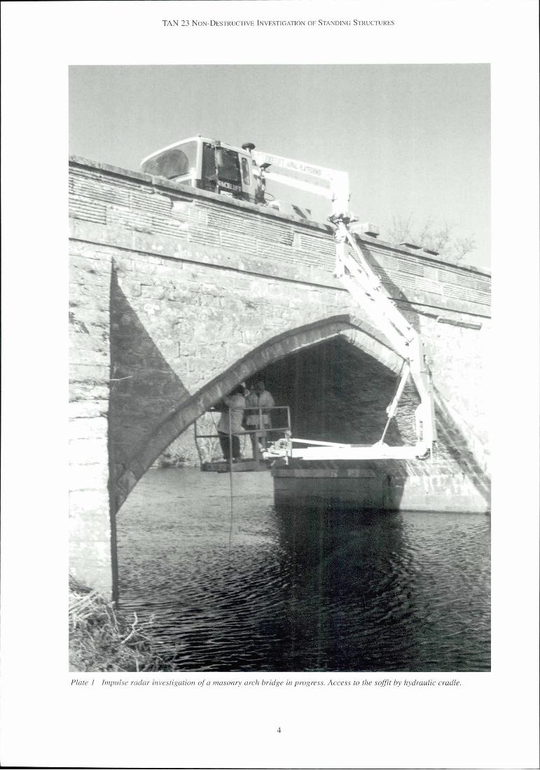
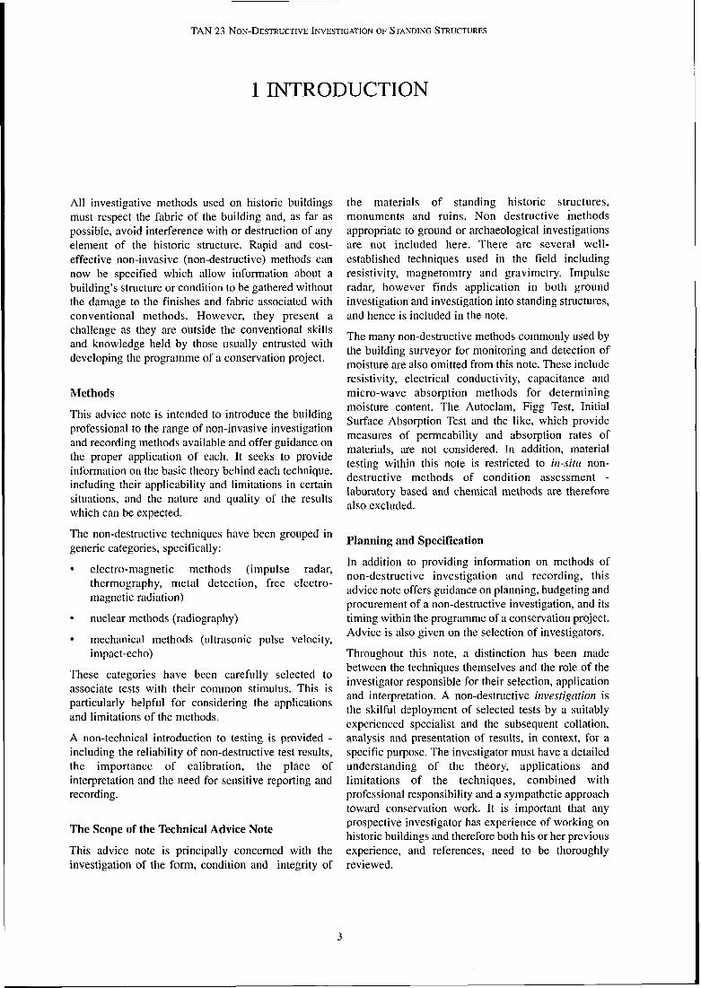
Plate I Impulse radar investigation of a masonry arch bridge in progress. Access to the sofit by hydraulic cradle.

TAN 23 NON-DESTRUCTIVE INVESTIGATION OF STANDING STRUCTURES
2 NON-DESTRUCTIVE INVESTIGATION METHODS
This section provides a general introduction to the only be established accurately if a sufficient number of techniques of non-destructive investigation discussed samples is taken. Clearly the identification of in subsequent sections and addresses the basic anomalous readings from a sample of three is much principles of testing. more problematic than identifying an irregular result
from a sample of twenty.
2.1 Introduction Note that when considering what constitutes a representative sample:
Testing, in essence, is the application of a stimulus to an object and the observation, capture, measurement the control sample may be unique for each object and recording of the object's response to that stimulus. (i.e. results from one brick structure do not This is as true of the doctor taking an X-ray of a automatically eliminate the need for a control patient's limb as it is of tapping a wall panel to see if it sample from another brick structure) is hollow. All tests can be regarded in this manner including: the size of the control is not absolute, and will vary
according to the test, the object and project 'simple' tests such as measurement of a distance or constraints such as access (see Chapter 6) volume or mass
For example, the inspection of five out of twenty 'destructive' (or 'invasive') tests such as distressed or defective window lintels will not tell you excavating a hole to find the position of a wall the condition of the remaining fifteen lintels. However, footing if carefully selected, the five may offer an insight into
'empirical' tests such as the loading of a sample of the likely condition of the others by establishing a probable failure mechanism, with parameters that can
stone to determine its crushing strength be used to easily assess the other fifteen lintels.
'non-destructive' tests such as locating a tie bar in- situ with a metal detector
2.2 Non-Destructive Testing In each case, the object's response to a stimulus is
The range of tests available and the combinations in measured: even measurements such as the
which they can be applied are extensive. The role of the photogrammetric survey of a building could be non-destructive investigations specialist is to apply
regarded as a test; observing and recording the structure's response to light - yielding information on skill and logic to the selection of the test method, to its
application and to analysis of the results. The sample form, dimension, colour.and proportion. applications given for each of the methods in
Non-destructive testing means simply that the object subsequent sections should be seen as illustrative, should not suffer material damage during the process therefore, and by no means exhaustive. of stimulation and data capture. These tests are therefore usually carried out in-situ. The tests in this advice note have been categorised as electro-magnetic, Reasons for Choosing Non-Destructive Testing
nuclear and acoustic, emphasising the nature of the The motives for specifying non-destructive methods stimuli that each test applies to the object. may include:
the need to preserve the fabric of the object being Sampling tested
Most materials and structures display heterogeneities the need to recover information about the internal (inconsistencies). Sometimes these anomalies are characteristics of an object latent or of no relevance to the non-destructive . investigation at hand (e.g. the veining in a marble slab). the need to avoid disrupting the object, its
environment andlor operation and use In order to identify these anomalies, the normal (or . 'control') state must be established. Such a control can the need to assess and review large structures
rapidly and economically
5
A

TAN 23 NON-DESTRUCTIVE INVESTIGATION OF STANDING STRUCTURES
the need to target subsequent test regimes that are more expensive andtor disruptive
other alternatives are not available
Irlformation Recovered Using Non-Destructive Testing
The following are the generic types of investigation which might be considered by conservation professionals:
verification of known detail (e.g. internal construction of a monument)
recording hidden detail for the purposes of archive
identifying heterogeneities (e.g. missing structural details)
locating specific targets (e.g. locating cramps, flue mapping)
materials characterisation (e.g. mapping deterioration, the condition of cramps, the loss of fines or presence of cavities in rubble construction)
Optimal Timing of A Non-Destructive Investigation
Testing primarily falls within the 'inspection' phase of a conservation project. However, experience has shown that an investigation also needs to be sequential, where successive tests are selected, and applied, based on the information obtained from earlier tests.
This sequence typically includes:
DOCUMENTARY REVIEW
Desk study of the object, its history and background (including existing records, written reports, anecdotal records, photographic records etc.) This will allow an assessment of the significance of the object to be made and yield valuable information on historic construction methods, materials and phasing. This will help develop the initial hypotheses that focus and describe a reasonable programme of preliminary testing.
SITE VISIT
A preliminary visual study, ranging from a simple overview or 'walk through', but possibly extending to a more detailed audit. An initial visual inspection, with the necessary expert interpretation of the visible defects and their likely causes, is often a valuable pre- requisite to defining what (if anything) requires investigation and what form this investigation will take. For example, water is often the main agent of decay within a structure and an experienced understanding of how the water acts on, and within, the structure can offer clues that can assist in the formation of a hypothesis and hence in the planning of an
investigation. Particular attention should be paid to any worsening of building defects noted in the documentary review as this will indicate ongoing instability.
PRELIMINARY TESTING
Typically, this stage may employ a range of non- destructive reconnaissance test methods (e.g. thermography, impulse radar) to provide an overview of the object and refine the historical and visual data gathered in the previous phases.
DETAILED TESTING PROGRAMME
This phase involves a review of previous testing and the deployment of subsequent complementary methods as appropriate. Tests are targeted at very specific queries raised by the combined desWvisual studies and initial testing.
2.3 Quality and Reliability
Common to all testing and central to accuracy and reliability are the methods and procedures used in data capture, storage, retrieval, analysis and interpretation. This is, perhaps, especially true of non-destructive testing, where the information may be only indirectly related to physical attributes. The accuracy (tolerances) of the techniques and calibration procedures are also relevant.
Data Capture, Storage and Retrieval
Capt~ire is usually achieved through one or more receivers, coupled (i.e. attached to or applied) to the object of the survey. The purpose of the couple is to optimise the transfer of signals to the receiver. For some methods, such as thermography or visual surveys, these receivers may be remote from the object, and the coupling medium is air. Other methods require an intimate contact or 'couple' with the object. This may require the use of another material as a medium, such as the gel used in ultrasonics.
A distinction should be made between capture and storage. To be reused effectively and reliably, data must be stored. Some forms of capture (e.g. the readout on a display, the audible tone from a metal detector or the reading on a theodolite) may not actually be stored at all. In cases where an automatic log is not carried out it is important that the operator makes some form of manual record of results.
Data may be stored in many forms of hard copy, including paper traces, or in computer files held on digital tapes or discs etc. The main purpose of this, apart from allowing analysis of the data, is the retrieval of raw data at a later date for review or to identify

TAN 23 NON-DESTRUCTIVE INVESTIGATION OF STANDING STRUCTURES
decisions and assumptions that have been made during Accuracy and tolerances are variable and are best the course of the project. understood in terms of what useful and practical
The systems used for this process of data capture, storage and retrieval fall under the I S 0 9000 Management and Quality Assurance Standards. Adherence to these standards demonstrates that reliable and effective management procedures are in place, an important factor in preserving the accuracy of data handling, analysis and reporting processes. It does not guarantee the quality of testing and its results.
Allalysis and Interpretation
All test data requires some form of interpretation and processing. This may be immediate and intuitive (stamping on the floor identifies that it is hollow by the sound that it makes) or deliberate and painstaking.
Interpretation is straightforward when dealing with quantitative measures (how many cramps are there in this wall?). It is less clear when a qualitative or relative assessment must be made, as with matters of method or opinion (Why is this mosaic cracking?). In this case,
information is required from a particular investigation. For example it is clearly unimportant to know the location of a tie to 5mm, say, when the number of ties is the actual query, or if the exposure for a physical examination, removal andlor repair can only be carried out to an accuracy of +_ 50mm. Similarly the primary value of a plot showing structural condition in the rubble core of a wall may lie in assessing the scale of works (e.g. 40% of the ashlar facing stones are debonded from the core) or regions of major concern (e.g. lower left quadrant, upper six courses etc.) rather than providing definitive boundaries (e.g. between intermediate degrees of separation of ashlar and rubble).
To arrive at the ad hoc assessment of 'useful and practical' expectations of accuracy, the conservation professional should refer back to the aims and the specific objectives of the investigation.
Calibration the selection and testing of a hypothesis should
When considering raw data from an investigation, facilitate interpretation. If the hypothesis is refuted
there must be some means of establishing the reliability then a new hypothesis may be selected and checked.
of this data. This requires calibration of the equipment, However if the hypothesis is not refuted then it is
against known constants (e.g. the velocity of radio strengthened and may be checked in another way with
waves through standard materials) which are published another test. This is the classical scientific method and
and available to the scientific community, as well as forms the central philosophy of a good investigation.
site specific readings. The investigator should have For example, a crack in the rendered external wall of a some system in place for doing this, either externally building may be due to subsidence, damp, shrinkage or (e.g. through a body like United Kingdom expansion of a finish or substrate, corrosion of Accreditation Service) or internally through an audited embedded ironwork etc. The size, shape and Quality Assurance system. orientation of the crack all give clues, but additional information is required. To this end, a hypothesis is chosen. Let us assume the hypothesis states "the structure is subsiding". We can now ask certain questions to test this hypothesis such as "is the structure prone to subsidence?', "is there evidence of subsidence elsewhere in the structure?', or "what are the material properties of the soil - is it prone to shrinkage?" Clearly some of these answers will come through testing only. The answers will establish the validity of the hypothesis.
Site-specific calibration is particularly valuable - either against objective physical parameters (e.g. velocities, thickness, densities etc.) or features revealed during the interpretation phase - the temptation to withhold some data from the investigator as a 'test' of the reliability of the test findings should be resisted. For example, readings interpreted by the investigator as discontinuities at the back of a retaining wall may take on a whole new significance when it is revealed that an earlier trial hole at the top of the wall uncovered what might be the capping stone on top of a buttress at the rear; those 'discontinuity' readings now can be interpreted as representing the buttress. Further analysis of the sign& may be possible, and may reveal The accuracy and allowable tolerances of non- periodicity (suggesting a structural design and intent) destructive tests are project-specific rather than and may yield valuable information on the actual absolute, although all findings should be traceable to a structural arrangement. By offering as much fixed and stated reference point, in the same way that information as possible to the investigator a more level surveys are traceable to an original datum. precise interpretation of the data, and therefore the structure, can be made.
7
TAN 23 NON-DESTRUCTIVE INVESTIGATION OF STANDING STRUCTURES
2.4 Limitations
No consideration of what a specific test can achieve is complete without a discussion of what the test cannot achieve. It is rare and often ill-advised to deploy non- destructive tests in isolation, without reference to some corroborative evidence, be it another test, historical records or visual observations. Non-destructive test data alone is rarely sufficient and the limits to which interpretation may be taken are finite.
From the definition of testing provided earlier, it is clear that testing is employed to 'interrogate' an object, asking specific questions to provide answers. To this end it must be appreciated that all techniques have their own applications and optimum environments where they can be expected to work well. i t is these which are set out in the subsequent sections.
There are at least five types of general limitations :
COMPLEX OBJECTS OR CONFIGURATIONS
Where there are many possible factors affecting the response of an object to a stimulus, (e.g. geometry, form, aspect, orientation, condition, boundary conditions etc.) it becomes increasingly difficult to 'interrogate' either the structure as a whole or individual components within it. Therefore the results of tests applied to densely reinforced concrete, multi- layered constructions etc. will be complicated, and their analysis to provide useful and practical information difficult.
ACCESS
Good access is imperative to recover good results (see section 6.2.1).
CONDITION
If the object is in poor condition it may not be possible to provide detailed comments on the construction arrangement, as signals are dominated by the condition responses, e.g. an investigation to locate chimney flues in a wall will be hampered if the wall is missing part of its rubble core - a formed void is frequently indistinguishable from a 'natural' void, other than by its form.
DIMENSIONS
SHAPE AND FORM
Small or thin objects can be difficult to assess. This is a problem when the dimensions of the object are small in relation to the size of the transmitter andfor receiver and the dimensions of the applied stimulus, e.g. wavelength of the signal.
2.5 Licensing and Other Legislative Considerations
The use of many of the instruments described and recommended here is restricted under a broad range of different legislation: brief notes of warning are attached to the description of each technique, but these should not be considered exhaustive, and it is always the responsibility of the user to ensure that any equipment employed is used in a manner fully compliant with any legislation.
Particular attention is drawn to the safety requirements in the application of equipment using ionising radiation: specialist training and safety procedures are required and the equipment should be acquired only from experienced and fully accredited organisations.
Most electronic equipment that is sold or leased in the UK will be compliant with the appropriate legislation for electromagnetic compatibility, but use of equipment involving radio frequency transmission must be compliant with the requirements of the Radio Communications Agency, and valid licences must be held where appropriate.
On certain protected sites (scheduled ancient monuments or monuments in the ownership or guardianship of the Scottish Ministers or of a local authority), Section 42 of the Ancient Monuments and Archaeological Areas Act 1979 applies to the use of metal detectors, but may also apply to many of the methods described in this note as they could be included in the broad definition of a 'metal detector' contained within the Act. Consent is required from the Scottish Ministers for the use of metal detectors on any such site. Advice should be sought from Historic Scotland about the protected status of sites and how to apply for consent.
The testing regime should reflect the scope and nature of the problem. Is the problem two dimensional - i.e. in the face of a building only? Is it three dimensional - i.e. are there voids located behind the facing stones of a wall? Is it four dimensional - i.e. is there a time factor involved?

TAN 23 NON-DESTRUCTIVE INVESTIGATION OF STANDING STRUCTURES
3 ELECTRO-MAGNETIC METHODS
This chapter deals with tests that apply different kinds of electro-magnetic stimuli to the object under study. The electro-magnetic spectrum includes the light, heat, radio and micro waves we are surrounded by every moment of our lives. Although we cannot necessarily feel or see them, they are real physical phenomena, well researched and understood and whose behaviour is governed by strict rules of physics.
The frequencies of different electro-magnetic wave forms are given on Page 2. Note that some of the techniques discussed are often referred to as geophysical techniques because of their origins as geological prospecting tools.
Each method is discussed under the following sub headings: application, theory and limitations, equipment and operation. The last section covers the collection of data, interpretation and analysis.
3.1 IMPULSE RADAR
Impulse Radar (also known as ground penetrating or ground probing radar) was first developed for use in mapping near-surface geological formations. However it is now recognised as an extremely versatile and powerful technique capable of providing a wide range of information relating to construction detail and condition of a structure and its elements. This includes the location, quantity, nature, shape, disposition and dimension of embedded objects, the identification of different material types and variations in their condition.
The wide range of information recovered frequently facilitates an understanding of the way in which a building or structure has been constructed and how it has been affected by time and use. Used appropriately, radar will provide an overview of the interior of a structure quickly and economically with a minimum of disruption.
3.1.1 Applications of Impzrlse Radar
Impulse Radar can be used on a wide variety of construction materials including stone, brick, asphalt, cement and concrete. The often sharp contrast of its response to inclusions of air, water, wood and metal within these materials contributes to an overall characterisation of the structure.
It has been used with good effect as the principal investigative tool on bridges and tunnels, ruins, historic buildings, modern concrete structures and archaeological remains. Typical construction information that can be recovered in these environments includes:
material thickness (e.g. in masonry constructions)
the identification of metallic fixings (e.g. cramps, dowels) and their condition
the location of the routes of flues and chases within walls
the location of services embedded within floors, behind panelling or in the ground
the identification of variations within material condition (e.g. cavities and voids in fill materials, microcracking of stone and concrete)
the assessment of bond between materials (e.g. a mosaic to its backing)
Impulse Radar has specific advantages over many other non-destructive techniques in that:
it is relatively rapid
it is truly non-destructive, affecting neither structure nor delicate finishes
it is a mapping technique providing a continuous measurement rather than point samples
the recovered data contains a wide variety of information
it facilitates an assessment of the whole structure rather than individual elements in isolation
One further important advantage is that it requires no special surface preparation, working well on stone, plaster, wallpaper and panelling in addition to friable decaying surfaces. This is because the stimulus it applies to the object can be transmitted through air. Minor surface irregularities are not a problem therefore and delicate finishes can be protected by covering in a suitable material such as bubble wrap.
3.1.2 Tlzeory and Limitations of Impulse Radar
RADAR is an acronym for Radio Detection And Ranging. The prefix 'impulse' or 'pulsed' refers to the manner in which the transmitted signal is generated
TAN 23 NON-DESTRUCTIVE INVESTIGATION OF STANDING STRUCTURES
and transmitted into the object, i.e. as a very short burst or pulse. Impulse Radar operates in the same manner as other echo systems such as SONAR (marine echo sounding). It is designed to transmit a pulse of radio energy into a solid material and collect the reflected 'echoes' for recording and interpretation. The major difference from other echo systems is that radar uses electro-magnetic and not mechanical waves.
Just as objects reflect or absorb light waves to varying degrees, so too do they reflect or absorb radio waves. The important difference is that many solid materials that are opaque to light waves will allow the transmission of radio waves. This is because different wavelengths within the electro-magnetic spectrum respond in different ways to different material properties: light waves respond to one set of properties of the material (i.e. optical); radio waves respond to a different set of physical properties (i.e. electrical). Different materials will often have different electrical properties, or will exhibit different electrical properties where their condition differs (e.g. if they are saturated or contain voids, are more or less dense etc.) Impulse Radar measures these electrical differences.
Just as the transmitted signal is a wave, so the echo, or returned signal picked up by the receiver, is also a wave. The various measurements made by the equipment characterise this wave form, including its phase, amplitude, frequency, the continuity of the signal and the time interval between transmission and reception.
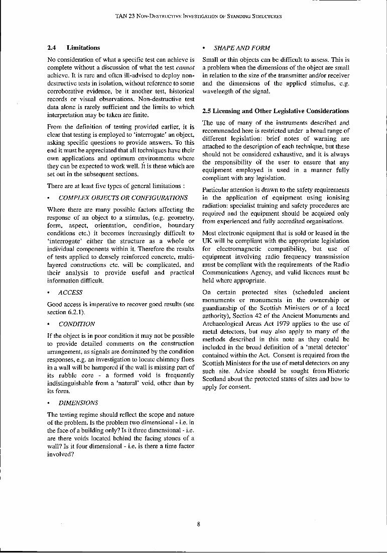
The following figure illustrates the basic theory of operation:
NOTE THAT SIGNALS ARE COLLECTED FROM STRUCTURAL FEATURES SUCH AS THE BACK OF THE WALL (MAIN PICTURE), AS WELL AS SMALLER HETEROGENEITIES WITHIN THE RUBBLE FILL (INSET)
POWER SUPPLY UN'T
RECORDING MEDIUM ANDIOR DATA VIEWER
Figure l Basic theory of impulse radar collecting data from a rubblefilled masonry wall.
Radar will be limited by the ability of the material to allow the transmission of electro-magnetic energy. Some materials carry this energy better than others as a result of their electrical characteristics. Some materials are particularly poor carriers, others block it altogether.
Two important characteristics of the transmission of electro-magnetic energy are penetration and resolution.
Penetration is the ability of the material to sustain an electric field and act as a good insulator. In practical terms this defines the depth from which data can be recovered.
Resolution is the process of defining whether those signals are 'useful' - a variable, even subjective, assessment. Note that sometimes the absence of a signal where it is expected can highlight material defects and therefore be reasonably considered 'useful'.
For example, sufficient energy may penetrate the structure of a wall so that reflections from the rear face (a large discontinuity) allow the thickness of the wall to be defined. This reflected energy may not be adequate, however, to identify (i.e. resolve) individual mortar beds, or iron cramps within the data.
The maximum depth to which useful information can be obtained in one material will vary from one object or structure to another, depending upon the particular condition of the materials under investigation. Penetration varies from depths of 1.5m or more, accompanied by high resolution, in dry, fine grained stone such as chalk and some sandstones. This decreases to about l m if the material is dressed into coursed and mortared blocks or as little as 500mm if the material is wet, contaminated and fractured.
Some common materials and configurations which affect penetration and resolution are discussed below:
Metal and closely spaced metallic features.
In most instances sheet metal, or a tight mesh such as chicken wire, will act as an impenetrable barrier to radar signals, giving rise to almost total reflection of the transmitted signal's energy. Closely spaced reinforcement (bars at <100mm centres) or multiple layers of reinforcement within a structure may produce signals which mask information from the structure beyond.
Water satilrated materials.
A high moisture content effectively slows and attenuates the transmitted signal. If the water makes the material more conductive (e.g. salt water) there will be a further reduction in penetration and resolution of detail. Note that these effects can be used to locate areas of high moisture content within otherwise dry materials.

Wet clay-rich materials. in a single unit known as a transducer which varies in size from a cigar box (high frequency) to a suitcase
The high conductivity of wet clays causes a significant (low frequency). The transducer is attached by a heavy
reduction in penetration, frequently a problem in duty cable to the recorder. The generatorlprocessor or
domestic rubble filled walls. Dry clays (e.g. bricks) control unit, has some form of signal control (time,
present no such problems. gain etc.), a means of viewing the generated and
Materials with a high ferro-magnetic content. received wave forms and a means of viewing the
Natural materials with a high iron content, such as some red sandstone will cause rapid attenuation of the radar energy and reduce penetration and resolution of detail. Some bricks, such as blue engineering bricks, may have a similar effect as a result of their haematite content.
sampled received signal. The control unit is connected to the recorder. Recording systems can use either digital or analogue data storage and recording formats. Both work in fundamentally the same way, the main differences lie in the way that data is stored and viewed.
Heterogeneous materials
Resolving small discrete targets and objects within a heterogeneous material (e.g. a cable or pipe work in loose fill) is very difficult because of the large number of signals - each void or discontinuity in the heterogeneous material generates a signal (collectively referred to as 'clutter') masking the desired signals.
Most frequently however it is the distress, damage or contamination which has occurred in the life of the structure that will effect the penetration of pulses and resolution of signals.
3.1.3 Equipment
The basic instrumentation for impulse radar testing comprises a signal generatorlprocessor, a transmitter and receiver (also known as antennae) and a recorder. The transmitter and receiver are frequently combined
Digital systems employ storage media such as hard disks or DAT tapes, and often produce file sizes in the order of 100 Megabytes per hour of work. Data is typically viewed on a small monitor controlled through a keyboard. Analogue systems usually print to paper, and may produce up to 50 metres of paper roll per hour. Data is viewed on the paper and the signals are viewed on a small built-in oscilloscope; control is through switches and dials. Analogue systems tend to be bulkier than digital systems.
A typical working arrangement is shown in Plate 2. Impulse radar equipment weighs a total of approx. 40kg and is powered by 12V car batteries. The equipment, while being shower proof, must be protected against sustained rain.
Digital data can be processed readily off-site to provide detailed analysis but is not easily handled on site. Analogue data is fixed at the time of capture and very accessible to expert interpretation both on and off-site.
Plate 2 Typical impulse radar equipment (analogue)

TAN 23 NON-DESTRUCTIVE INVESTIGATION OF STANDING STRUCTURES
The antennae are of different frequency and have to locate archaeological features beneath the ground to different purposes and uses. High frequencies, approx. depths of 2-3m may use a survey grid with survey lines 1000MHz, or 1 GHz, have shorter wavelengths and spaced 2m or more apart. small physical 'footprints' (i.e. the area bombarded by the pulses of radio energy). These are high resolution devices which will identify small objects or closely spaced layers. The shorter wavelengths are, however, also absorbed more rapidly in a given material, thus they are of lower penetration than longer wavelength devices with transmission frequencies of lOOMHz or lower. These longer wavelength devices are used where greater penetration is required and resolution is not so important - e.g. looking for near-surface geological features.
Table 1 gives some guidelines on the performance of certain transmitter types, under typical circumstances.
3.1.4 Operation
Data Collection
Surveying with Impulse Radar is achieved by drawing a transducer over the surface under investigation at a controlled speed. Plate 3 shows a transducer being drawn across the floor by means of an attached handle. Information is typically collected from a grid of survey lines set out to cover the area under investigation. The optimum spacing between survey lines is governed by
Some types of investigation require that the survey lines are located in response to the expected locations of some specific structural feature. An investigation of ashlar stonework will typically concentrate on the collection of data from a series of horizontal lines located at the positions of the horizontal joints in the wall face (where iron cramps or dowels may be found) and along the centre-line of each block course (where the thickness of the block can be easily measured).
the size of the features which are expected to be found, their depth within the structure and the frequency (and hence footprint size) of the transducer being used. For h example, an investigation to locate voids within the rubble core of a wall of approx. 600-1100mm in thickness would normally be carried out by collecting data from continuous recordings along a grid of survey lines at approx. 500mm centres, whilst an investigation Plate 3 Impulse Radar survey in progress to locate
suspended stoneflags in a cathedralfloor.
Frequency Maximum Reasonable Mical Uses
(MHz) effective resolution
penetration (mm) range (mm)
1000 800 300 Detailed structural investigations, location of cramps, thickness of stone facing, detection of cracking within materials etc.
900 1300 500 Determining general structural layout, measurement of wall thickness, location of voids and flues, structural changes, locating buried services etc.
General condition and thickness of walls where >approx. 1500mrn thick,
locating, buried services etc.
300 3500 NIA Archaeological investigations in near surface, walls and subdivisions
80 5000 NIA Archaeological investigations of large areas, foundations, floors
35 l0000 NIA Archaeological investigations in large open areas: layout of dwellings etc.
Table I Typical Penetration, Resolution and Uses of Diflerent Frequency Transmitters

1 TAN 23 NON-DESTRUCTIVE INVESTIGATION OF STANDING STRUCTURES
Surveys are normally carried out by a two person team, one person operating the signal control and recording apparatus and the other controlling the transducer. One person should also monitor the data and make an early appraisal of its implications and the other monitor the structure. Photographs or video film of an anomaly or feature taken during the site work can give added insight to any subsequent interpretation.
Impulse Radar is a rapid technique which requires an appropriate access system. Very detailed information can be collected when moving the transducer at speeds of 10 metres a minute (0.6 kmlhr) and prior planning to ensure that enough material can be accessed to maintain that speed is well worth the effort.
The simple requirement for access is that the transducers or antennae are kept in reasonably intimate contact with the surface under investigation (within approx. 30mm) and can be moved at a steady speed along the chosen survey line. Hand access to the surface is best, but an assortment of poles and extending arms can be used to increase the operator's reach. Beyond this, access equipment is needed. This should be kept as simple as possible whilst satisfying the needs of the survey.
Interpretatiorz of Zmpzilse Radar Data
A technique like Impulse Radar requires a high degree of interpretation in order to make sense of the data gathered. The electrical changes of relevance are frequently subtle and deceptive, and are represented as a multi-dimensional (i.e. non-numerical) information stream.
In keeping with non-destructive tests in general, it is never possible to be fully confident that the features detected are in fact what they appear to be: the findings of radar testing are based on a series of indirect measurements and the interpretation of electrical and electro-magnetic signals. For this reason the accuracy of a set of findings relies heavily upon the expertise and experience of those carrying out the interpretation of the data. This expertise is likely to have been built up partly empirically, from the results of many corroborative destructive tests of coring, drilling and exposure, and partly from an in-depth understanding of the physics involved. A good investigator also looks to confirmation from observation, complementary tests and a sound knowledge of the material being inspected.
developed and checked, discussion can result in further efficient and fruitful lines of analysis.
Figure 2 shows the relationship between the data recovered during an investigation to locate underfloor chambers and the interpretations made to produce the final drawings. Note the coincidence between each hyperbola in the recovered data and the interpreted void beneath. The collection of a complete data set enables the location and arrangement of the underground network of chambers to be deduced.
Reporting
It is often possible to provide preliminary results immediately after collection of the data, on site, although this is likely to be restricted to marking the location of a particular feature or features of interest, or a brief description of the materials or structural layout. The majority of the results are best presented on drawings of the structure, either in plan, elevation or section, as appropriate. These are generated off-site after a period of data processing.
As a rule of thumb, relocation accuracy is typically *10% of the distance between known points, thus survey marker points at l m centres will probably produce a survey of features relocated to +100mm.
3.2 THERMOGRAPHY
Thermography or thermographic imagery detects and records levels of electro-magnetic radiation in the infrared band - jus t as photography records levels of electro-magnetic radiation in the visible light band.
Thermography has been widely used for a number of years as a monitoring and inspection tool for extremes of heat in many different industries such as power generation and refrigeration. Technological developments have increased the sensitivity of the equipment, facilitating its use across a wider variety of environments and tasks where the thermal differences may be small.
The main advantage of the technique is that, like a camera, the system may be operated remotely from the object, images can be produced at speed, and the final result is reminiscent of the form and shape of the visible object. Storage and manipulation is facilitated by the use of digital media, while the nature of the images and data recovered lends itself to a straight- - -
During the interpretation phase, interaction between forward preliminary analysis. the investigator and the building professional is at its most valuable. As a range of hypotheses are being

I TAN 23 NON-DESTRUCTIVE INVESTIGATION OF STANDING STRUC~URES
IMPULSE RADAR SCAN L1 IMPULSE RADAR SCAN L2
L SUBSURFACE CHAMBER
INlERPRETOD SECDON OF RADAR SCAN L1
PLAN - FLOOR CONSlRUCllffl
KEY BMCKWoRK
mmK COURSED AND KNNTED STONEWORK
? INDElERMlNAlE CONSTRUCICN
-&WRFACE CHAiam 2 INTERPRETED SECllffl OF RADAR SCAN L2
d I
E @z
BRICK UNED DUCT
LocAncti OF mncAL FM
PLAN - LOCAllON OF UNDERFLOOR CHAMBERS
KEY - SURMY UNE
SUBSURFAE CHAMBER
SCALE
Figlire 2 Sample of imp~ilse radar data recovered and the drawings generated from it during an investigation to locate ~tnderjloor chambers
TAN 23 NON-DESTRUCTIVE INVESTIGATION OF STANDING STRUCTURES
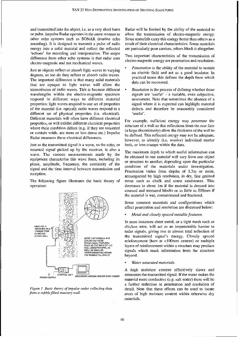
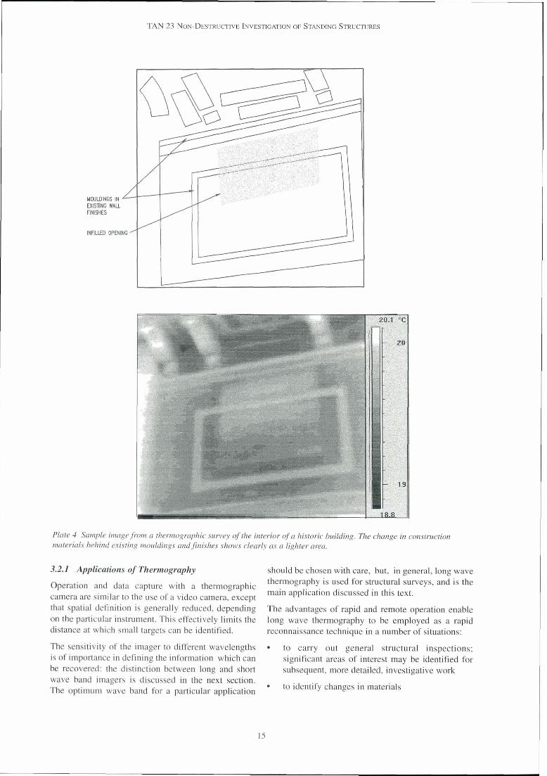
Plate 4 Sample image from a thermographic survey of the interior of a historic building. The change in construction materials behind existing mouldings andfinishes shows clearly as a lighter area.
3.2.1 Applications of Thermography should be chosen with care, but, in general, long wave
Operation and data capture with a thermographic thermography is used for structural surveys, and is the main application discussed in this text. camera are similar to the use of a video camera, except
that spatial definition is generally reduced, depending The advantages of rapid and remote operation enable on the particular instrument. This effectively limits the long wave thermography to be employed as a rapid distance at which small targets can be identified. reconnaissance technique in a number of situations:
The sensitivity of the imager to different wavelengths to carry out general structural inspections; is of importance in defining the information which can significant areas of interest may be identified for be recovered: the distinction between long and short subsequent, more detailed, investigative work wave band imagers is discussed in the next section. The optimum wave band for a particular application to identify changes in materials

1 TAN 23 NON-DESTRUCTIVE INVESTIGATION OF STANDING STRUCTURES
to record construction; alterations made to a structure may be identified because of the differences between original and new materials.
Specific situations where long wave thermography has been successfully used include:
the identification of construction features such as timber frames, chimney flues or concealed/infilled openings
the identification of structural defects such as loss of bond, delamination, cracking and voids
the location and tracking of retained moisture and rising damp
the detection of services such as hot water pipes, electrical wiring (mains, alarms, telephone etc.)
the inspection and monitoring of fragile murals.
A sample image recovered during such surveys in shown in Plate 4.
3.2.2 Theory and Limitations of Thermography
Thermal radiation, like light and radio waves, is part of the electro-magnetic spectrum and can be described in terms of amplitude, frequency andlor wavelength. The visible part of the spectrum is the only part to which our eyes are sensitive. Thermal radiation is in the infra- red band, i.e. with a wavelength longer than visible light (red light has the longest wavelength).
All objects warmer than absolute zero emit thermal radiation. The higher the temperature the greater the energy output and the shorter the wavelength. As a rule of thumb, objects we would consider hot, i.e. at or above body temperature, radiate principally short wave infra-red, while cooler objects, i.e. around room temperature, radiate long wave infra-red. Long wave systems (8 - 12 pm) are more suitable for investigating the structure of historic buildings, therefore, while short wave systems (2 to 5 pm) are most appropriate for locating zones of high temperature heat flow, e.g. identifying hot gases escaping from a chimney, or tracking central heating pipes in a floor.
The middle band (5 to 8 pm) is the characteristic incident radiation from the sun, and most imagers are insensitive to this radiation, which would otherwise blur all images.
The basic principles of optical theory, describing how light waves are transmitted, reflected and refracted can be applied directly to thermal radiation, to provide a basic understanding of the application and use of thermo-graphy as a branch of photo-graphy. The important distinction to make is that most objects only reflect light, whereas almost all objects we are likely to encounter can also radiate or emit thermal energy.
The total thermal output measured at the surface of any particular object is affected by three characteristics of the object:
Reflectivity - the amount of external energy that is reflected rather than absorbed by that object
Transmissivity - the amount of energy that is transmitted through an object from a heat source within or beyond the object
Emissivity - the amount of internal energy that can be emitted by the surface of an object
The reflectivity of an object can cause high levels of reflected thermal energy which would dominate the observed output from a surface. Generally it is desirable that this is as low as possible. As may be predicted, this is a problem of many 'shiny' surfaces, such as metals, glass and even some glazes.
A material which acts as a good insulator has a low transmissivity and may effectively mask deeper heat sources, such as a hot water pipe buried in the ground or under a floor: however, the variable fill in the trench over the pipe, or the materials covering the pipe in a chase may be assessed as the amount of energy reaching the surface varies.
The thermal energy output by an object at any given temperature is dependent on the emissivity of its material - its ability to emit thermal radiation. Minor changes in material can have quite different effects on the output. For instance metals have a low emissivity, and thus appear cold to an imager; covered with a paint of high emissivity, the same metal at the same temperature appears 'hotter'. The distinction in emissivity between two limestones from different quarries is normally clearly identifiable even when there is no 'visible' difference.
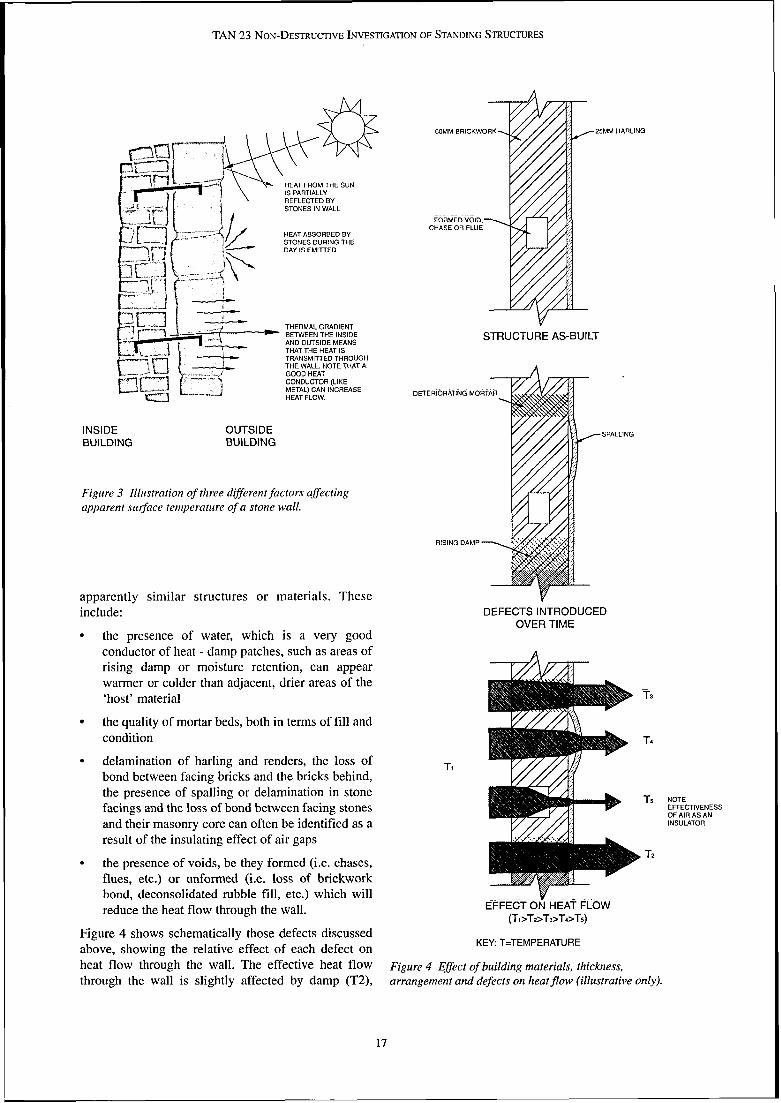
These properties are shown in Figure 3.
Most building materials such as masonry and concrete have a high emissivity and low reflectivity. Transmissivity of these materials is generally such that while a 'hot' buried object (e.g. a hot water pipe or duct in an old chimney flue), may be detected at depths of 200 - 300mm, a 'cold' buried object (e.g. a drain pipe or empty flue) may not be detected beyond a wall, half a brick thick. The thermal gradient across the materials in the latter case is unlikely to be sufficient to produce an appreciable difference in the emitted radiation at the face.
As with the analysis of impulse radar information, contrast is important; the different properties of broadly similar materials such as blockwork, bricks and mortar can yield surprisingly high levels of definition in the recovered images. Defects are often identified through the contrasting response of
TAN 23 NON-DESTRUCTIVE INVESTIGATION OF STANDING STRUCTURES
6OMM BRICKWORK 25MM HARLING
HEAT FROM THE SUN IS PARTIALLY REFLECTED BY STONES IN WALL
-. . . . . . . . FORMED VOID.
CHASE OR FLUE HEAT ABSORBED BY STONES DURING THE
THERMAL GRADIENT BETWEEN THE INSIDE AND OUTSIDE MEANS
STRUCTURE AS-BUILT THAT THE HEAT IS
CY) TRANSMITTED THROUGH THE WALL. NOTE THAT A GOOD HEAT CONDUCTOR (LIKE METAL) CAN INCREASE HEAT FLOW. DETER~ORAT~NG MOR
INSIDE OUTSIDE BUILDING BUILDING
Figure 3 Illustration of three different factors affecting apparent s~rgace temperature of a stone wall.
RISING DAMP
apparently similar structures or materials. These include:
OVER TIME the presence of water, which is a very good conductor of heat - damp patches, such as areas of rising damp or moisture retention, can appear warmer or colder than adjacent, drier areas of the -
'host' material T3
the quality of mortar beds, both in terms of fill and condition T4
delamination of harling and renders, the loss of T1 bond between facing bricks and the bricks behind, the presence of spalling or delamination in stone Ts NOTE facings and the loss of bond between facing stones EFFECTIVENESS
OF AIR AS AN and their masonry core can often be identified as a INSULATOR
result of the insulating effect of air gaps T2
the presence of voids, be they formed (i.e. chases, flues, etc.) or unformed (i.e. loss of brickwork bond, deconsolidated rubble fill, etc.) which will reduce the heat flow through the wall.
(TI>Tz>Ts>T~>Ts) Figure 4 shows schematically those defects discussed
KEY: T=TEMPERATURE above, showing the relative effect of each defect on heat flow through the wall. The effective heat flow Figure 4 Effect of building materials, thickness, through the wall is slightly affected by damp (T2), arrangement and defects on heatflow (illustrative only).
17

TAN 23 NON-DESTRUCTIVE INVESTIGATION OF STANDING STRUCTURES
increasingly affected by deteriorating mortar work (T3) and spalling renderlbrickwork (T4), and greatly affected by the presence of formedlun-formed voids (T5) [i.e. Tl>T2>T3>T4>T5].
It is often just as informative to measure heat inflow as it is to measure output from an object. This is effectively a measure of the difference in rates with which heat energy is taken up (absorbed) or emitted by the object and its materials. For example, if variations in the frnishes of an internal wall need to be identified then the survey could be carried out using only normal thermal cycles. Early in the morning, when the temperature of the surface materials in the wall will have stabilised to ambient air temperature, no heat will flow: by turning on the heating, lights and moving people or other warm bodies through the room , the air will be heated and a flow of heat into the relatively cooler wall will result. However, at night, when the room cools as people leave and heating and lights are switched off, the relatively warm materials in the wall will emit heat, and result in a flow of heat into the relatively cooler air.
Correctly timing a thermographic survey to coincide with optimal heat flows is crucial and is perhaps the greatest skill required for field thermography. In the
Plate 5 Thermographic inspection in progress. Hand held camera is panned across the wall and the results viewed as an image on the trolley mounted processor Power is supplied as an unspillable (gel type) 12V car battery.
case of observing an occupied historic building or monument, heat flow out of the building will be sourced from any solar heat stored plus any transmission of heat from the interior of the building. However, at times during the day it is possible that the thermal response of the wall under investigation may be "swamped" by the incident energy source (i.e. the sun). Variation in the structural formation of a wall and in the quality of build will have an effect on the rate of heat flow and can therefore potentially be mapped by the investigation.
3.2.3 Thennographic Survey Equipment
Thermographic equipment available on the market today ranges in size from small hand held cameras to relatively large scanners and signal process and control units. Many factors must be considered and applied to the selection of the most appropriate instrument for a particular task. These include wavelength (discussed briefly above), resolution, range and performance and are important considerations for the investigator.
The different systems available record images in a number of ways, from the smallest cameras (very short wave length, relatively inexpensive, recording on film) to sophisticated high resolution digital systems recording direct to disk or tape. Digital storage has the advantage that it allows a great deal of filtering and post-processing to be carried out on the images.
As a guide, the thermographic equipment for surveying historic structures will typically consist of a video sized scanner and control unit. A standard arrangement is shown in Plate 5. This weighs up to 20kg and is powered by a 12V car battery although developments are constantly reducing the size and weight of the equipment. The equipment, while being shower proof, requires protection from sustained rain.
3.2.4 Therrnographic Surveys
In the same way that Impulse Radar surveys must balance the requirement for penetration against resolution, surveying with thermographic equipment involves balancing the requirements for perspective (coverage) and the objectives of the investigation (the size and nature of the targets). The scanner must be operated at a distance and aspect appropriate to the object and survey, but close enough to be able to identify the smallest targets.
Data Collection
Since thermographic systems can be operated at some distance from the structure under investigation a great deal of work can be carried out from ground floor level. Where it is necessary to get higher, either neighbouring buildings or powered access platforms offer the fastest,

TAN 23 NON-DESTRUCTIVE INVESTIGATION OF STANDING STRUCTURES
most effective means of access. If a wall has a complex example, if surveying the entire wall of a building profile or relief, access to any 'blind spots' (e.g. behind it is possible to accurately relocate (sometimes to carvings, the upper surfaces of cornices etc.) will be an accuracy of better than k20mm) by referencing re~uired. the collected data to each individual stone block.
This method has the added advantage of making As with P ~ ~ ~ ~ ~ ~ ~ P ~ Y , various length lenses are the relationship between detected features (such as available to suit particular needs. As a rule of thumb, and dowels), and block joints more buildings and other structures of up to four storeys can obvious. be inspected from ground level. Beyond this, - resolution decreases significantly. the second method of relocation should be used
For the reasons already discussed, one of the most effective times to carry out a thermographic survey of occupied buildings is on a cold, dry, still night when the heating inside is turned on. This results in the maximum flow of heat through the walls. Failing this, artificial heat sources can be applied and their effect monitored. Direct sunlight is also a good source of thermal energy - its effects are often best monitored at the end of the day.
Extensive knowledge of the principles of heat flow, including conduction, convection and radiation, are required to plan and execute an effective thermographic survey. A detailed discussion of these is beyond the scope of this advice note. Failure to understand these principles can lead to the recording of thermal effects of no interest, or the misinterpretation of results.
The interpretation of thermographic images is not restricted to the simple identification of 'hot' or 'cold' areas. A general knowledge of structures and materials in addition to an understanding of the structure under investigation in particular is required to draw reasoned and informed conclusions about the cause of the 'hot' or 'cold' spots which form an image.
Reporting Tlf errnographic Findings
Detected features can be reported, where appropriate, by direct marking onto the structure or by means of a relocation system that allows transfer of the detected features onto drawings.
There are two principle relocation methods:
the first (and fastest) is simply to relocate from the physical features in the thermal images. This is particularly helpful when a conventional (optical) video or photographic record is collected simultaneously with the thermographic survey. For
where greater precision is required, or the structure under investigation has few distinguishable features (e.g. when a wall is surveyed close up). This technique involves laying out a survey grid with reference 'marks' that are visible to the infra red scanner. The 'marks' generally consist of highly reflective metal shapes or wires, as appropriate. With this system it is normally possible to achieve relocation to an accuracy of better than *10% of the distance between measured points.
Because of the accessibility of the images recovered by thermography it is sometimes possible to provide preliminary results whilst on site. Results are usually presented either as enhanced thermal images (if features of interest can be easily resolved) andlor interpreted features marked on drawings of the structure, in plan, elevation or section, as appropriate. A sample image was given in Plate 4.
3.3 METAL DETECTION
Of all the non-destructive instruments and tools employed, metal detectors are probably the best known, but have also acquired a notoriety, as they are also the favoured cheap and accessible tool of the treasure hunter. Their use therefore has been severely regulated on any site classified as having any potential archaeological interest. It is a criminal offence (under section 42 of the Ancient Monuments and Archaeological Areas Act 1979) to use a metal detector on a scheduled ancient monument, or a monument in the ownership or gaurdianship of the Scottish Ministers or of a local authority, without the written consent of the Scottish Ministers. It is also an offence to remove from such a monument any object of archaeological or historical interest found using a detector. Advice should be sought from Historic Scotland regarding any proposal to use a metal detector on a standing structure which is a scheduled ancient monument.

TAN 23 NON-DESTRUCTIVE INVESTIGATION OF STANDING STRUCTURES
3.3.1 Applications for Metal Detection 3.3.2 Theory and Limitations of Metal Detectors
As their name suggests, metal detectors are used to find Metal detectors rely on the electro-magnetic metallic 'targets' such as cramps, reinforcement bars in phenomenon that an electrical current, passed through structures and various other conductive 'targets' in a conductive material, will induce a weak magnetic archaeological investigations. field around the conductor. Conversely, a magnetic
field will induce a weak electrical current in a Metal detectors all have an effective maximum 'range'
conductive material brought into the magnetic field. within which the presence of the targets is detected. This is extremely variable and depends largely on the There are two common types of metal detector, each target properties (see section 3.3.2) and configuration using slightly different principles of operation. They of the detector's 'search head' (see section 3.3.3). The are based on material characteristics of magnetic appropriate range for hand held devices is between reluctance and electrical conductivity. Their use in the approximately 50 and 1000mm, increasing to different types of detector is discussed in some detail approximately 3000mm for larger ground searching here. devices. The technique can also yield limited
All magnets and magnetic materials have magnetic information on the size, orientation and material type
fields - including the earth. A magnetic field is the area of 'targets' in certain conditions. of influence around the magnet where the effects of the While the relative ease of operation and relatively low magnetic force may be felt - in a metal detector this equipment cost makes metal detection an extremely becomes the search area. A magnetic field can best be accessible technique, failure to understand the thought of as a series of lines (flux lines) circling round principles often leads to unrealistic expectations and a magnet and running from one end to the other disappointing results. through its area of influence, as can be easily
FLUX LINES IN MAGNETIC FIELD (SEARCH AREA)
(a) PRIMARY MAGNETIC FlELD WHEN SEARCH HEAD IN FREE SPACE
(a) SEARCH HEAD IN FREE SPACE FERRO MAGNETIC TARGET
FERRO SEARCH FlELD
MAGNETIC TARGET
(EG IRON CRAMP)
COILS ACT AS SENSORS
(b) SEARCH HEAD WITH TARGET IN MAGNETIC FlELD
(C) POWER SWITCHED OFF, THE SECONDARY MAGNETIC FlELD IN THE TARGET. GENERATED BY THE EDDY CURRENT IS DETECTED BY THE SEARCH HEAD
Figure 6 Metal Detection using electrical conductivity method
Figure 5 Metal Detection using magnetic reluctance method.

TAN 23 NON-DESTRUCTIVE INVESTIGATION OF STANDING STRUCTURES
demonstrated by placing a magnet beneath a piece of paper on which iron filings have been spread.
The magnetic rel~rctarice method involves the measurement of reluctance (or 'resistance') along a magnetic path within a magnetic field. Reluctance is measured using a search head containing two coils wound around the ends of a 'U' shaped ferrite core. An electric current is passed through one of the coils resulting in a magnetic field being generated through and around the ends of the core. This gives the core a northern and southern pole (see Figure 5).
This field induces a current in the second coil. The size of this current is determined by the 'reluctance' of the material in the search area: the higher the reluctance, the lower the current in the secondary coil. Introducing a magnetic object into the search area will alter the reluctance of the search area.
The size of the current through the secondary coil can therefore be used to measure the proximity and size of magnetic targets, such as metallic objects.
Metal detectors which use the principle of magnetic reluctance can produce unstable andlor unreliable readings. This is due largely to the use of ferrite cores in the search heads. The cores, and therefore the readings, can be affected by factors such as temperature and the orientation of the core relative to the Earth's magnetic field. The readings are also influenced by any material with magnetic properties such as magnetite and haematite. Due to this instability, magnetic reluctance has largely been superseded by the electrical conductivity method.
The electrical conductivity method uses a search head containing one or more air-cored coils; thus avoiding the problems of the ferrite core. It is sometimes known as a 'pulse induction eddy current' method because it measures the temporary, induced magnetic field of a conductive, mctallic target generated by an electrical current in the search head coil.
An electrical current is passed through the coil causing a primary (or transmitted) magnetic field. Unlike the reluctance method, the generated magnetic field is not continuous, but is switched on and off by switching the electrical current in the coil on and off. At the instant that the current is switched off the primary magnetic field collapses. This induces 'eddy' currents to flow in any conductive targets within the search area (see Figure 6).
These eddy currents will decay very rapidly as there is no source of energy to maintain them. While the time scale of this 'persistence' effect is only in the order of millionths of a second, it still outlasts the primary magnetic field. The eddy-currents generate a secondary magnetic field which propagates back to the search
head and induces a flow of current in the same coil that generated the primary field (see Figure 6).
The metal detector measures the coil voltage after a delay which is long enough to miss the effects of the collapsing primary field, but short enough to include the eddy-current signal (if present). The resulting signal strength is proportional to both the reflected field strength and its persistence.
Material Properties of Targets
If a target is to be detected by this method, it must be conductive. Some magnetic materials are not conductive and will not always be detected therefore. This is shown in the following table.
hlaterial hlagnetic ? Conductive ? Detectable ?
foil, stainless steel X X X
ferrite, iron oxide,
mineralised soil d X X
copper, aluminium X d d
iron. steel d d d
Table 2 Effect of Magnetic and Conductive Material Properties on Detectiorz
Non-magnetic nzaterials wit11 poor conductivity such as stainless steel produce an eddy current with a very short persistence, i.e. the current is said to 'decay' rapidly. This decay time is comparable with timings (i.e. sampling delay) in the receiver circuitry and therefore makes it very difficult to measure the return signal from the target. The sample delay time can however be shortened to detect such materials, albeit with a lesser sensitivity.
A magnetic non-conductor (e.g. ferrite) will be magnetised by the primary field but demagnetises immediately on removal of the field. Such materials will not induce any signal in the coil therefore.
A magnetic conductor however, (e.g. iron) will produce a signal in exactly the same way as a non- magnetic conductor (e.g. copper), but the strength of the response will be magnified by the 'magnetic conductivity' of the target. This phenomenon is related to the target material and the effective size of the target (i.e. its shape and orientation). The concept of 'effective size' of targets is discussed further below.
While these categories account for most metallic target types, in a few situations a significant signal is received from certain non-conductive, magnetic materials. This is due to a phenomenon known as magnetic viscosity. When the primary magnetic field is removed from
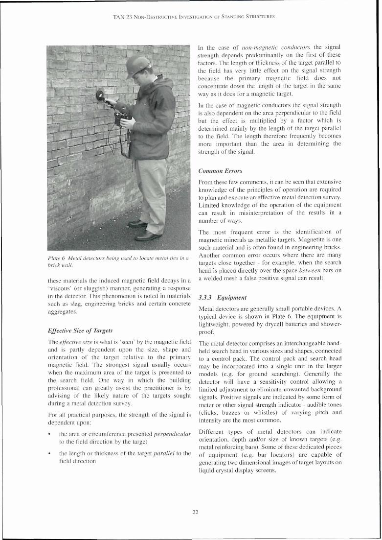
TAN 23 NON-DESTRUCTIVE INVESTIGATION OF STANDING STRUCTURES
Plate 6 Metal detectors being used to locate metal ties in a brick wall.
these materials the induced magnetic field decays in a 'viscous' (or sluggish) manner, generating a response in the detector. This phenomenon is noted in materials such as slag, engineering bricks and certain concrete aggregates.
Effective Size of Targets
The effective size is what is 'seen' by the magnetic field and is partly dependent upon the size, shape and orientation of the target relative to the primary magnetic field. The strongest signal usually occurs when the maximum area of the target is presented to the search field. One way in which the building professional can greatly assist the practitioner is by advising of the likely nature of the targets sought during a metal detection survey.
For all practical purposes, the strength of the signal is dependent upon:
the area or circumference presented perpendicular to the field direction by the target
the length or thickness of the target parallel to the field direction
concentrate down the length of the target in the same way as it does for a magnetic target.
In the case of magnetic conductors the signal strength is also dependent on the area perpendicular to the field but the effect is multiplied by a factor which is determined mainly by the length of the target parallel to the field. The length therefore frequently becomes more important than the area in determining the strength of the signal.
Common Errors
From these few comments, it can be seen that extensive knowledge of the principles of operation are required to plan and execute an effective metal detection survey. Limited knowledge of the operation of the equipment can result in misinterpretation of the results in a number of ways.
The most frequent error is the identification of magnetic minerals as metallic targets. Magnetite is one such material and is often found in engineering bricks. Another common error occurs where there are many targets close together - for example, when the search head is placed directly over the space between bars on a welded mesh a false positive signal can result.
3.3.3 Equipment
Metal detectors are generally small portable devices. A typical device is shown in Plate 6. The equipment is lightweight, powered by drycell batteries and shower- proof.
The metal detector comprises an interchangeable hand- held search head in various sizes and shapes, connected to a control pack. The control pack and search head may be incorporated into a single unit in the larger models (e.g. for ground searching). Generally the detector will have a sensitivity control allowing a limited adjustment to eliminate unwanted background signals. Positive signals are indicated by some form of meter or other signal strength indicator - audible tones (clicks, buzzes or whistles) of varying pitch and intensity are the most common.
Different types of metal detectors can indicate orientation, depth and/or size of known targets (e.g. metal reinforcing bars). Some of these dedicated pieces of equipment (e.g. bar locators) are capable of generating two dimensional images of target layouts on liquid crystal display screens.

ELEVATION
LEAD PINS RETAINING WTESrn
CRAMPS POSSIBLY MNG BLOCKS BACK TO S'IRUCTURAL BM CKWORK
SECTION A-A THROUGH CORNICE
KEY
CRAMP M N G 1WO ASHLAR BLOCKS TOGETHER
CRAMP M N G ASHLAR ROCK INTO STRUCTURAL BRICKWORK BEHIND
Figure 7 Sample of res~llts from a combined metal detector and impulse radar investigation
TAN 23 NON-DESTRUCTIVE INVESTIGATION OF STANDING STRUCTURES
3.3.4 Metal Detector Surveys of the stones adjacent to the perpend joint. In severe cases, the cracks lead to spalls, often exposing the corroded cramp.
Data Collectiorz The results of an investigation using metal detectors to
An investigation using metal detectors is carried out by map cramp locations is shown in Figure 7.
drawing a search head over the surface of the object. The optimum pattern and spacing between sweeps of the search head is governed by the target properties, 3.4 FREE ELECTRO-MAGNETIC RADIATION including material type, effective size (as described in
Free electromagnetic radiation (FEMR) techniques section 3.3.2) and depth, and the specific properties of l
cover a family of tools using very similar principles. the search head used.
They were originally used for locating metallic Metal detection requires that the search head is in services buried under the ground but have since been reasonably intimate contact with the surface under adapted to locate a wide variety of targets in other investigation. This is most easily achieved if the environments. FEMR techniques typically are used to operator can gain 'hand' access to all areas under track kno~vrz linear features or targets (e.g. pipes, investigation. When arranging access it is essential that services and beams etc.) which are not necessarily the search head is not shielded, i.e. the field it generates conductive. This can be compared to metal detectors can operate in all directions around the head. Steel which are used typically to firld small conductive ladders (and scaffolding) should be avoided as they targets (e.g. metal cramps in stonework), will generate a positive response when they are in the search head's field - wood or aluminium ladders should 3.4.1 Applicatiorzs of FEMR be used.
Applications immediately relevant to the investigation When steel scaffolding is used it is preferable to erect
of historic structures and monuments include: it with a gap of at least 300mm between the scaffold and the surface under investigation to reduce the risk of tracking metallic services such as power cables, swamping signals from targets in the building with old domestic gas lines, domesticlrain water pipes signals from the scaffold. Aluminium scaffolding has within walls and floors the advantage of being non-magnetic and less likely to
tracking metallic structural units such as tie bars interfere with readings taken during the investigation.
and steel sections
tracking non-metallic openings such as chimney Z~lterpretatiorz artd Reportirzg ,
flues, old sewer lines, cisterns etc. There are essentially two results from a metal detector
The last of these applications is achieved by survey - either there is a target or there is not - and
introducing a linear conductive element into the therefore little analysis off site is required. Targets, e.g.
otherwise non-conductive target (e.g. a wire along a metal cramps in stone joints, can either be marked
sewer). In addition to detecting and tracking the directly onto the structure, if appropriate, or noted on
targets, in certain circumstances it is possible to give an detailed measured survey drawings.
estimate of depth and the nature of the target (e.g. The latter facilitates the accurate relocation of targets power cable etc.) where it is unknown. by measured reference to physical features, e.g.
The effective maximum depth of penetration is reveals, mouldings or individual stone blocks.
extremely variable and ranges between approximately Alternatively a survey grid referenced to some suitable
l m and 15m, depending on the equipment used, the fixed datum point can be reproduced and the targets
nature of the target and the strength of signal radiated located within it.
from the target. Corroding embedded ironwork often produces cracking or spalling of the host stone; the mapping and cross referencing of these crackslspalls with the
3.4.2 TIzeory arzd Limitations of FEMR
identified metallic targets will increase the confidence FEMR techniques all work by detecting radiated of the survey findings. electro-magnetic signals. These can be considered
'active' signals where they have been induced within The form of a metallic target can often be assessed by
the target by an actual stimulus. Passive signals, on the noting the nature and form of associated surface
other hand, can be defined as all the signals that are features such as cracks or spalls. For example, a
present in a target that have not been introduced corroding iron cramp located across the perpend joint
artificially. between two stones often produces diagonal cracking
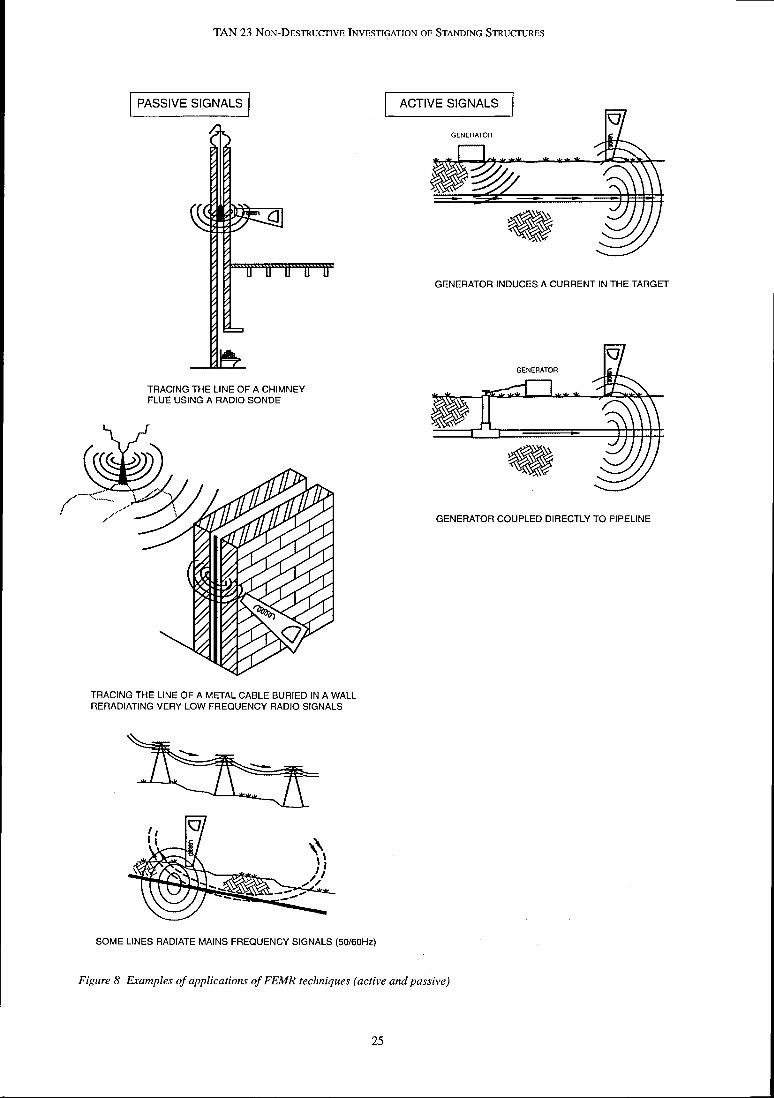
TAN 23 NON-DESTRUCTIVE INVESTIGATION OF STANDING STRUCTURES
TRACING THE LlNE OF A CHIMNEY FLUE USING A RADIO SONDE
GENERATOR COUPLED DIRECTLY TO PIPELINE
TRACING THE LlNE OF A METAL CABLE BURIED IN A WALL RERADIATING VERY LOW FREQUENCY RADIO SIGNALS
ACTIVE SIGNALS m' GENERATOR
GENERATOR INDUCES A CURRENT IN THE TARGET
GENERATOR
SOME LINES RADIATE MAINS FREQUENCY SIGNALS (50160Hz)
Figure 8 Examples of applications of FEMR techniques (active and passive)

TAN 23 NON-DESTRUCTIVE INVESTIGATION OF STANDING STRUCTURES
Plate 7 FEMR methods being used to trace an iron drain pipe behind a wall
FEMR differs from metal detection in that both 'passive' and 'active' signals are detected. The two passive signal frequencies that are most commonly present in linear conductive targets are:
between 50Hz and 60Hz found in electrical power cables and conductive targets that have passed through the electro-magnetic field generated by the power cables
between 15kHz and 20kHz found in targets acting as aerials, receiving and re-transmitting long wave radio signals.
Active signals are introduced to the target either by direct connection or induction.
Direct connection as its name implies is the introduction of a known signal (of specific frequency) into the target through a direct connection of a signal generator to the target - e.g. if the generator is connected to the stop cock of a water pipe, this introduces a signal which can be measured. It offers the best chance of tracking an individual target through a congested area as the receiver can 'lock' on to the 'known' signal radiated by the target.
Induction is the introduction of a signal to a target by ensuring that it is within range of the magnetic field generated by the signal generator. This is very close to
the principle behind some metal detectors which detect the magnetic fields induced in and 'radiated' by conductive targets. It has the obvious advantage that no direct connection to the target is required.
A range of scenarios is shown in Figure 8.
A wide range of frequencies is commonly employed and a number of considerations must be borne in mind when selecting the appropriate frequency. Higher frequencies are better at inducing a signal in a target and travel well on small diameter lines, but transfer of the signal to other targets is more likely. In general, lower frequencies are better at maintaining a signal over longer distances but are more likely to be affected by interference because they are nearer the frequency of mains power. Frequency selection should be based therefore, on an understanding of the target and electromagnetic theory.
Finally, it is important to consider the environment of the target, in particular the material surrounding it. If the target is surrounded by relatively conductive materials (e.g. wet clay) the signal is stronger than if it is surrounded by dry sand or air.
Limitations of FEMR
Complications can occur when the electro-magnetic field emitted by the target becomes convoluted or is cancelled out. This can occur when:
there are a number of linear conductive targets in close proximity
target lines change direction
power cables are wound in such a way as to cancel out the field from the individual wires that make up the cable.
Limited knowledge of the target, environment or equipment can result in failure either to induce a signal, to detect it, or to interpret it correctly.
3.4.3 Equipment
FEMR techniques typically employ a hand-held receiver aerial, operated by itself or in conjunction with a separate transmitter unit. Typical equipment is shown in Plate 7. Generally, the receiver aerial weighs in the order of 5kg, is powered by internal dry cell batteries and is water proof.
As with the metal detecting equipment, the aerial is usually equipped with a sensitivity control allowing a limited adjustment to eliminate unwanted signals. Positive signals are usually indicated by a meter andfor other signal strength indicator such as audible tones (clicks, buzzes or whistles) of varying pitch and intensity.

TAN 23 NON-DESTRUCTIVE INVESTIGATION OF STANDING STRUCTURES
3.4.4 FEMR S~~rveys In the case of non-conductive targets (such as a clay
Some knowledge of electro-magnetic theory is required to effectively plan and execute an FEMR investigation. These surveys are often time consuming, as despite the relative ease of operation, building up a record from essentially abstract signals requires considerable concentration and attention to detail,
water pipe or a chimney flue) the introduction of a linear conductive element or a transmitter can present some practical problems that need careful consideration and planning prior to commencement of a survey. These might include obtaining access to an open end of the service.
especially where an area is congested with several targets. Interpretation and Reporting
Data Collectiorz Like the results of a metal detector survey, FEMR readings require little or no off site interpretation and can therefore either be marked directly onto the object To minimise disruption where a target is fully or presented on drawings, whichever is more concealed, an attempt should be made to trace the appropriate. The results of a chimney flue location target by using either a passive signal or an induced
active signal. The alternative is direct connection survey using a variety of techniques including FEMR
requiring exposure of a small part of the buried target are given in Figure 9.
to attach the signal generator which may result in some disturbance of the original fabric.
If a target is to be tracked internally along a floor then furniture may have to be moved. Carpeting and floor finishes do not generally affect the signal. If a target is to be tracked up a wall some form of access to high levels may be required.

TAN 23 NON-DESTRUCTIVE INVESTIGATION OF STANDING STRUCTURES
Figure 9 Specimen results from an investigation to track flues in a party wall using a variety of techniqrres, including FEMR
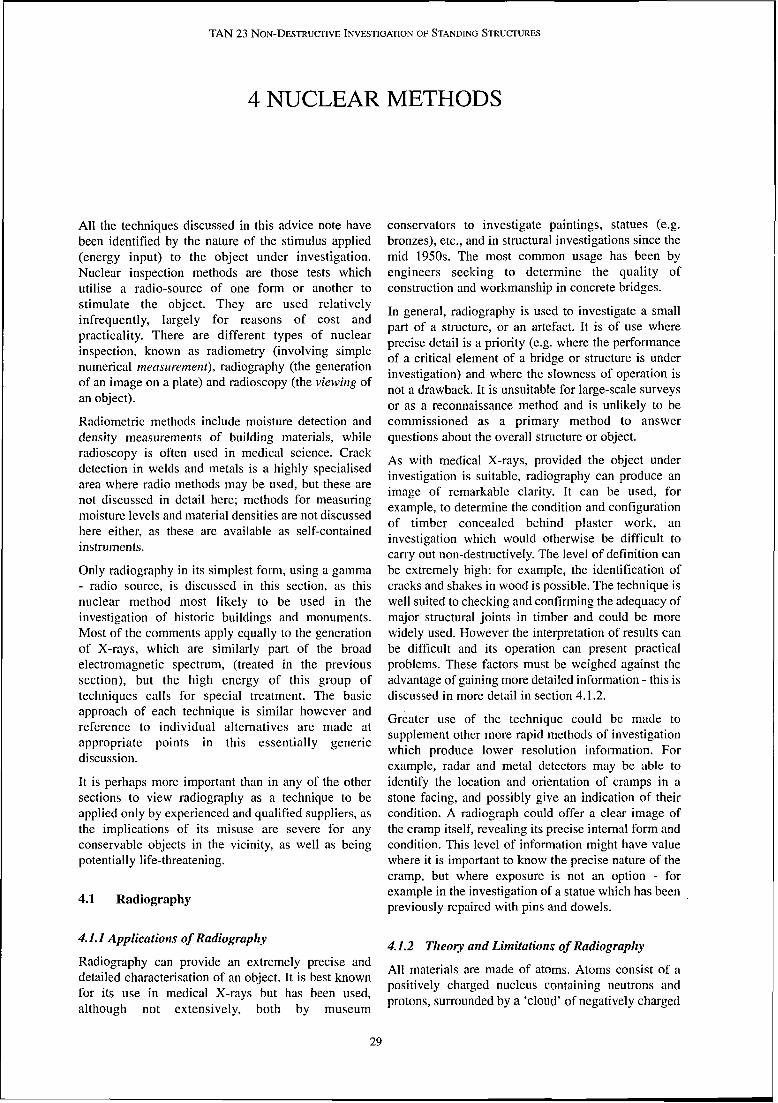
TAN 23 NON-DESTRUCTIVE INVESTIGATION OF STANDING STRUCTURES
4 NUCLEAR METHODS
All the techniques discussed in this advice note have been identified by the nature of the stimulus applied (energy input) to the object under investigation. Nuclear inspection methods are those tests which utilise a radio-source of one form or another to stimulate the object. They are used relatively infrequently, largely for reasons of cost and practicality. There are different types of nuclear inspection, known as radiometry (involving simple numerical measlrrement), radiography (the generation of an image on a plate) and radioscopy (the viewing of an object).
Radiometric methods include moisture detection and density measurements of building materials, while radioscopy is often used in medical science. Crack detection in welds and metals is a highly specialised area where radio methods may be used, but these are not discussed in detail here; methods for measuring moisture levels and material densities are not discussed here either, as these are available as self-contained instruments.
Only radiography in its simplest form, using a gamma - radio source, is discussed in this section, as this nuclear method most likely to be used in the investigation of historic buildings and monuments. Most of the comments apply equally to the generation of X-rays, which are similarly part of the broad electromagnetic spectrum, (treated in the previous section), but the high energy of this group of techniques calls for special treatment. The basic approach of each technique is similar however and reference to individual alternatives are made at appropriate points in this essentially generic discussion.
conservators to investigate paintings, statues (e.g. bronzes), etc., and in structural investigations since the mid 1950s. The most common usage has been by engineers seeking to determine the quality of construction and workmanship in concrete bridges.
In general, radiography is used to investigate a small part of a structure, or an artefact. It is of use where precise detail is a priority (e.g. where the performance of a critical element of a bridge or structure is under investigation) and where the slowness of operation is not a drawback. It is unsuitable for large-scale surveys or as a reconnaissance method and is unlikely to be commissioned as a primary method to answer questions about the overall structure or object.
As with medical X-rays, provided the object under investigation is suitable, radiography can produce an image of remarkable clarity. It can be used, for example, to determine the condition and configuration of timber concealed behind plaster work, an investigation which would otherwise be difficult to carry out non-destructively. The level of definition can be extremely high: for example, the identification of cracks and shakes in wood is possible. The technique is well suited to checking and confirming the adequacy of major structural joints in timber and could be more widely used. However the interpretation of results can be difficult and its operation can present practical problems. These factors must be weighed against the advantage of gaining more detailed information - this is discussed in more detail in section 4.1.2.
Greater use of the technique could be made to supplement other more rapid methods of investigation which produce lower resolution information. For example, radar and metal detectors may be able to
It is perhaps more important than in any of the other identify the location and orientation of cramps in a sections to view radiography as a technique to be stone facing, and possibly give an indication of their applied only by experienced and qualified suppliers, as condition. A radiograph could offer a clear image of the implications of its misuse are severe for any the cramp itself, revealing its precise internal form and conservable objects in the vicinity, as well as being condition. This level of information might have value potentially life-threatening. where it is important to know the precise nature of the
cramp, but where exposure is not an option - for
4.1 Radiography
4.1.1 Applicatiorzs of Radiograplzy
example in the investigation of a statue which has been previously repaired with pins and dowels.
4.1.2 Theory and Limitations of Radiograplzy Radiography can provide an extremely precise and
All materials are made of atoms. Atoms consist of a detailed characterisation of an object. It is best known
positively charged nucleus containing neutrons and for its use in medical X-rays but has been used,
protons, surrounded by a 'cloud' of negatively charged although not extensively, both by museum

TAN 23 NON-DESTRUCTIVE INVESTIGATION OF STANDING STRUCTURES
electrons. Different materials have different numbers competent and experienced practitioner will advise on of protons, neutrons and electrons, yielding different the correct equipment, and the maximum resolution physical and chemical properties (e.g. density, the type achievable in the particular materials. of bond they can form with other materials, their state
Nuclear methods of investigation offer a means of at a given temperature etc.). identifying the type and arrangement of different
Radioactive materials that occur naturally (e.g. materials in an object by their differential absorption or uranium) are different from other materials because dispersion of radioactive particles. Effectively there are their particular atomic arrangement is unstable; they two methods of radiography, both involving exposing spontaneously decay or disintegrate by 'losing' mass. an object to a radioactive source and recording the This is usually accompanied by a release of energy in effects. These are: the form of electromagnetic waves. This rate of decay
through transmission (a material's 'half-life') can vary from seconds to centuries in different materials. The shorter the half- back scatter life the more unstable or radioactive the material.
Radiography takes advantage of the sensitivity of some There are three basic types of radioactive emission: materials to radiation in the same way as photography
records light reflected from an object. A radiographic alpha (a) rays, comprising relatively heavy alpha
image is formed by exposing fluorescent screens or particles (a positively charged nucleus of two neutrons and two protons)
photographic material to the radiation after it has 'scattered' or passed through the object.
beta (p) rays, comprising negatively charged electrons (beta particles) moving almost as fast as the speed of light
Through Transmission Zmaging
Through transmission, as its name implies, places the gamma (y) rays - electro-magnetic waves with no
object under investigation between the radioactive charge. The X-rays used for medical work are very
beam and the screen or radioactive sensitive material. similar to gamma rays, with a wave length
This 'detector' records those particles which pass between ultra violet and gamma waves (see
through the object and impinge upon it (this is Appendix A for the electro-magnetic spectrum).
described further in section 4.1.3). Objects and features The different forms of radiation pass through (or are located by this method are therefore seen in silhouette. absorbed by) different materials at different rates. The Medical X-rays are an example of through important factors governing this process of absorption transmission. are the 'radio density' of the material and its thickness. Alpha rays have very little penetrative effect (approx. Back Scatter 7cm in air) compared to beta particles (approx.750cm in air), and gamma radiation (infinite range in air) are Back scatter methods place the detector on the same much more penetrative than either. Building materials side of the object as the radioactive beam to recover are penetrated with variable efficiency: organic dispersed particles in the manner of an echo sounder materials - wood and leather, and simple compositions (described further in section 4.1.3). This method is such as plaster - are easily penetrated, but complex used for measuring material density and moisture materials such as brick, stone and metals are content. It is an indirect method of investigation as it progressively less so. measures the efSect of exposing the object to the radio
source. A clear distinction needs to be drawn between penetration - the distance over which usuable radiation Density is measured on the basis of the scatter and can be transmitted, and resolution, the ability to attenuation (weakening) of the radiation while identify useful information about objects to be studied. moisture is measured by the capture of hydrogen ions A large cobalt or irridium source may penetrate which are generated by the hydrogen nuclei present in lOOOmm of masonry, but a nail will only reasonably be water, produced as a result of the exposure to the detected in a wall at about 300mm from the point of radiation. observation, and its size and shape accurately determined at about 150mm. Scatter of the radiation Practical Considerations from objects between the target and point of observation blur the image. With nuclear methods of investigation, a balance must
be struck between the need for information and the portable is limited in disruption, risks, cost and effort required to recover it.
penetration by the energy levels, and in resolution by Specific considerations include: the distance of the imaging plate from the object. A
30
TAN 23 NON-DESTRUCTIVE INVESTIGATION OF STANDING STRUCTURES
Health & Safety
The key question here is: can a safe environment be ensured for people - operatives, staff, and bypassers - during the course of the survey? Exposure to radioactivity is a well documented health hazard and great care must be taken to avoid long term exposure to radioactive sources. This may also generate a further question: is it acceptable to restrict access to the public andfor occupants for a long period during data collection? Some form of shielding or screens (often lead) will almost certainly be required to prevent unnecessary exposure of people and objects to the radioactive source while data is being captured. This almost certainly precludes the use of radiography on an exploratory or reconnaissance basis. The investigator should be fully aware of the relevant legislation surrounding the control, use and transportation of radioactive materials - this information is readily available from the Health & Safety Executive.
Effects of Exposure to Radiation on Materials
10s for a partition wall formed of 150mm lath and plaster over timber can be expected, positioning the plate and source such that the optimum results are achieved takes a considerable time, as does the arrangement of a safe working environment.
4.1.3 Equipment
Radiographic equipment is bulky and cumbersome but essentially portable. For through transmission, the transmitter and detector are placed separately on either side of the object. Various sources or transmitters can be used to generate the source of radiation the object is exposed to, usually in the form of a focused beam. These include electrically powered guns and elements like Cobalt 60. A picture of a transmitter is shown in Plate 8. The detector contains an imaging screen, which fluoresces with a white light when excited by the beam. The light generated exposes a photographic film within the cassette, and an image of the internal structure is formed.
In buildings containing delicate finishes or housing In radioscopy, the film can be replaced with a video furniture and other artefacts, careful consideration camera or any other system that responds to visible should be given to the problems of placing protective light. This introduces further sophistication to the screening for objects and people. The screening is equipment and increases its size and complexity. heavy and often cumbersome, giving rise to the possibility of accidental damage, particularly as it will often require repositioning for each image. In addition, little is known of the potential damage to finishes and materials at a molecular andfor atomic level, particularly when more penetrative, highly radioactive sources are used. However, for most forms of survey, the levels of exposure to radioactivity are low and of short duration, therefore there is negligible residual effect or contamination of the structure or object under investigation. As with medical X-rays, danger can come from repeated or prolonged exposure to the radioactive source. The technicians exposed daily to the equipment and sources wear, or work, behind some form of shielding, while a patient receiving a single exposure does not.
Access
This is discussed further in Chapter 6, however it is worth noting that of all the methods discussed in this note, the equipment required for radiography is among the heaviest and least manoeuvrable. Coupled with a requirement for very specific positioning and perspectives, the success of the survey is particularly dependent upon appropriate access being achieved.
Rates of progress
Progress is relatively slow and laborious. Typical photographic plate sizes are 25 X 20 cm, which is a very small image in terms of the total surface of a building. While average exposure times in the order of
Although radiometry has not been discussed in detail in this advice note, it is worth noting that radiometric moisture and density gauges can be of use in conservation work. They are relatively compact, simple pieces of equipment, that frequently use the back scatter principle, described previously, for measurement. The radioactive source is placed against the surface or within the body of the material, by means of a probe. If required the detector can be placed in the body of the material, also by means of a probe. In this sense the technique is not always non- destructive - some disturbance is inevitable if a probe is to be placed within the fabric.
4.1.4 Radiographic Surveys
Health & Safety
With any nuclear method of investigation there are stringent Health and Safety regulations governing the operation, handling and transportation of the radio- active source. Adequate protection for both operatives and the public must be ensured and a period of notice of the use of such a source can be required. Further information is readily available from local offices of the HSE. Both nuclear and all radiographic methods must only be undertaken by qualified experts who are contracted to provide a safe working environment for their activities which complies with current regulations and recommendations.

TAN 23 NON-DESTRUCTIVE INVESTIGATION OF STANDING STRUCTURES
Specification shots produce distorted images with considerable
A precise specification and definition of the scope of work is essential to the success of a nuclear method of non-destructive testing because of the cost penalty and practical difficulties which arise when site work has to be repeated. If the precise images required of the object
interference from scatter, which blurs the image. The best results are obtained when the plate is close to the hidden feature, although clustered andor distant objects will be blurred. It may be necessary to take an image from both sides therefore.
are not recovered, if they are out of focus or blurred or When using X-ray equipment a stable power source taken from the wrong perspective, the test must be will be required. Single phase mains is normally repeated. The critical and detailed nature of the adequate although power consumption is too large to information which prompts the commissioning and allow the use of batteries - making the technique justifies the cost of a nuclear method, is unlikely to be unfeasible in remote environments unless a heavy provided by partly successful results. generator can be provided.
Interpretation
Consideration has been given in this note to the simplest form of equipment, where an image is captured on a photographic plate. Traditionally plates must be developed before the quality and coverage of the image can be established. This effectively prevents an in-situ interpretation, although relatively portable processors and the development of X-ray sensitive film (as opposed to exposure of photographic film to X-ray sensitive fluorescing materials) offer a reduction in processing times.
The radiographs generated are full scale images which require careful interpretation. Simple inclusions such as nails in wood (a very high contrast and distinctive shape) can be readily identified while more complex and lower contrast features such as cracks or complex overlays of materials require specialist interpretation. Note that subtler nuances of the image (shadows, marks etc.) can result from non-structural sources (e.g. interference patterns) as well as 'real' features.
Modem radioscopic systems, incorporating a video camera with a fluorescing screen, offer more flexible ways of working and allow instant access to the results. Recording onto video tape gives reasonable definition
Plate 8 Portable Radioactive Source (COBALT 60) but for high quality definition comparable with photographic plate, a digital recording system is
Data Collection required.
The selection of the correct source is critical and Reporting depends on the expected overall absorption. Less
penetrative radiation can offer a better definition A radiography report should include both a copy of the between materials but must penetrate sufficiently to original radiograph and a written andlor graphic produce the information required. interpretation. In complex constructions this will
almost certainly include a dimensioned drawing of the For through transmission radiography, the source object investigated, as revealed in the radiograph.
(transmitter) is typically an electrically driven gun, as used in dental surgeries, which directs a beam into the object. Alternatively a radioactive source may be used to guide the particles into a focused stream.
Particular attention has to be paid to keeping the beam perpendicular to the plate (receiver): oblique angled

TAN 23 NON-DESTRUCTIVE INVESTIGATION OF STANDING STRUCTURES
5 ACOUSTIC METHODS
The third category of non-destructive methods covers techniques that apply mechanical stimuli to an object and measure and record the object's response. These are distinct from other 'physical' tests such as smoke or ball tests (used for flue location) or endoscopy which are not discussed here as they are considered essentially intuitive. Methods for testing and measuring the dynamic response of a whole structure are also excluded from this section as these are not considered to be of direct relevance to the conservation of historic buildings and monuments.
This advice note limits its discussion therefore to the testing and measurement of materials, structures and small objects by two mechanical methods: ultrasonic pulse velocity (UPV) and impact-echo.
5.1 Introduction to Acoustics
Before any methods are considered in detail, it is helpful to understand the basic theory of acoustics.
We are all familiar with the 'tap' test in its various forms, e.g. rapping knuckles on a plastered wall to locate timber studs, stamping on a floor to identify voids below, the wheel tapper hitting a train wheel with a hammer to check its integrity. Each of these tests applies a physical stimulus and measures the acoustic response of the object by ear. Variations in the tone and volume (i.e. frequency and amplitude) of the response give a qualitative assessment of the condition of the object or the materials behind it. Other characteristics of the response are the phase and wavelength, which, together with the frequency and amplitude describe a wave.
Acoustics is the study of sound. Sound waves are mechanical waves produced by a vibrating object in which particles oscillate backwards and forwards about their 'resting' position, i.e. the waves are a physical displacement of the media in which they are travelling, therefore (and in contrast to electromagnetic waves), mechanical waves cannot move through a vacuum (e.g. space).
In general terms, as an object vibrates it sends out waves which move or propagate through the medium surrounding the object. The nature of the waves depends upon the elastic properties and density of the medium. In solids, mechanical waves comprise:
longitudinal or compression waves (Primary or P- waves)
transverse or shear waves (Secondary or S-waves)
surface waves (Rayleigh waves)
Usually only longitudinal waves are measured for the simple reason that they are the fastest moving and reach the receiver first. These are cycles, comprising alternating high pressure (compression) and low pressure (rarefaction) zones. The waves move at different speeds depending on the material and its phase (i.e. whether it is gas, liquid or solid).
Note that fluids such as air, water etc., only support longitudingal compression waves where the displacement is in the same direction as the wave. The human eardrum is coupled to the environment by air - sound therefore is a compression wave.
Uses for acoustics vary from the identification of variations in material integrity (e.g. voids in concrete, depth of cracking in a surface, delamination in a sandstone block) to the establishment of certain material and element parameters (e.g. compressive strength of stone or brick, material density, slab thickness).
5.2 Ultrasonic Pulse Velocity Measurements
Ultrasonic pulse velocity (UPV) measurement is a simple point test of material integrity and arrangement. It works by measuring the time travelled by an acoustic pulse through a material over a fixed distance; this is then used to calculate a velocity which may be compared for variation against a known constant. This is explained in more detail in section 5.2.2
5.2.1 Applications of UPV
The measure of velocity is used in two ways:
minor variations are attributed to changes in elastic modulus and are used to comment on in-situ strength
major variations (beyond those reasonably explained by changes in strength) are attributed to discontinuities or cracks in the material.

TAN 23 NON-DESTRUCTIVE INVESTIGATION OF STANDING STRUCIZTRES
It is therefore likely to be used later in an investigation, Velocity Calculation after more general reconnaissance methods have identified areas of the object for further detailed study. It is a simple test in principle and has been used for many years around the world, particularly (in an engineering environment) for the study of concrete integrity.
The travel time of the acoustic pulse in milli seconds (ms) is measured, and comprises the raw data. This does not allow an intuitive interpretation. Therefore, before conclusions can be drawn, it is wise to look for insight from other reports and information. These may be simple visual records or reports from other non- destructive methods. The investigator is looking for supporting evidence to explain andlor support the readings obtained.
Typical applications include:
the assessment of material compressive strength
To calculate the velocity, the time ( t ) taken for a pulse to travel a known distance (d) between the transmitter and receiver is measured. The velocity (v) is then calculated as follows:
v = d / t
Once the acoustic pulse velocity for a material is known it can be used in one of three ways:
to give an indication of material integrity
to calculate the mechanical properties of the materials (e.g. elastic moduli, uni-axial compressive strength)
to identify local variations within the materials.
An assessment of material integrity is normally achieved by comparing the calculated pulse velocity against the published 'benchmark' velocity for the same material (this figure can also be calculated).
the assessment of material integrity - for example Velocities which differ significantly from the in masonry lintels
benchmark values may indicate areas where the the identification of cracks and their depth in material integrity has been compromised (e.g. micro- materials such as stone, concrete etc. cracking, delamination, cracking etc.). Statistical
analysis of the collected data allows local variations to More sophisticated instrumentation which measures
be found within the material even in the absence of and records other signal properties (e.g. amplitude and
benchmark readings: it is assumed that variations phase) can be wed for extended studies between results obtained from the same material in including:
similar areas of an object indicate a change in material material thickness - for example in plaster work, condition. stone slabs
In the same way, mechanical properties obtained by locating delaminations in a laminar structure - this technique should not be used as absolute peeling of 'thick' finishes, separation between measurements but can be used to indicate variations in plaster coats, spalling stonework. strength: as the velocity in a simple and undamaged
medium will be a function of the density (e) and It is worth noting that metallic as well as non-metallic
elasticy (r), measuring the velocity in a constant objects can be assessed with this method; ultra-sonics
density medium will give the elasticity, from which the are used in industry, including the aerospace industry
strength can be derived. Few building materials are for assessing the integrity of welds.
sufficiently homogeneous for this simple relationship to apply absolutely. This does not however preclude its
5.2.2 Theory and Limitations of UPV use as a relative tool, looking for changes or - -
dicontinuities in a material, or the estimation of broad Mechanical waves travel through different solids at
categories of strength. different velocities; this is independent of their frequency. Note that the range of frequencies used by Figure 10 shows the approximate relationship between UPV are beyond the audible range, approximately 20 acoustic velocity and compressive strength for kHz to 300 kHz, hence they are referred to as concrete, although the same approximate relationship ultrasonic. fits for most materials: best fit empirical values have
been used and the shaded area o f either side of the UPV measures the velocity of compression waves, and
curve gives an approximation to the error margins. At the velocity of a wave through a material is a function
the bottom left of the graph the velocity levels off at the of:
typical velocity for uncemented gravel - about the density of the material 1.8Km/s, and at the top right at about 4KmIs is high
the elastic properties of the material
the type of wave.
quality hardened concrete. In between is the range of interest where an approximately linear relationship exists between strength and velocity, which can be used to determine the residual strength of a material which has been damaged through stress or decay.
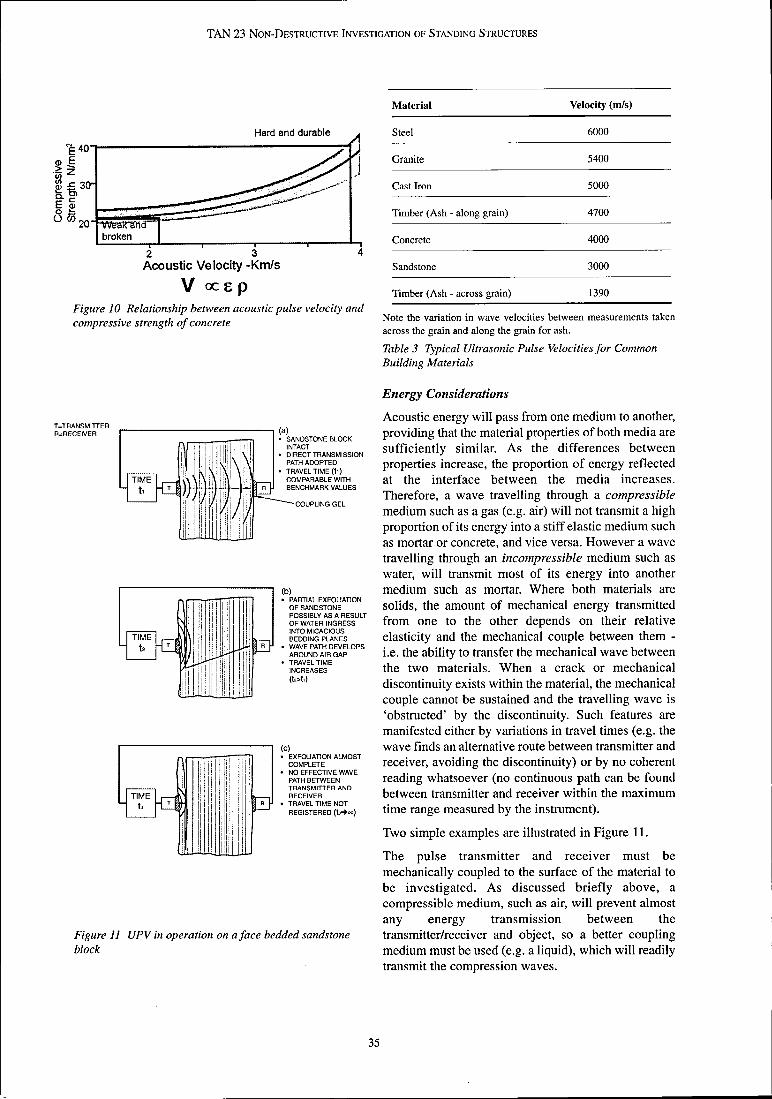
TAN 23 NON-DESTRUCTIVE INVESTIGATION OF STANDING STRUCTURES
Hard and durable A
Material Velocity (mls)
S t e e l 6000
broken I 1 , I I I
2 3 4 Acoustic Velocity -Krn/s
v ocsp Figure 10 Relationship between acoustic pulse velocity and compressive strength of concrete
SANDSTONE BLOCK INTACT . . . . . . - . DIRECT TRANSMISSION PATH ADOPTED TRAVEL TlME 111) COMPARABLE'W~TH BENCHMARK VALUES
-COUPLING GEL
PARTIAL EXFOLIATION OF SANDSTONE POSSIBLY AS A RESULT OF WATER INGRESS INTO MlCAClOUS BEDDING PLANES WAVE PATH DEVELOPS AROUND AIR GAP TRAVEL TlME INCREASES (t>t?)
,-, EXFOCIATION ALMOST COMPLETE . NO EFFECTIVE WAVE PATH BETWEEN TRANSMITTER AND RECEIVER TRAVEL TlME NOT REGISTERED ( M m )
Figure I1 UPV in operation on a face bedded sandstone block
Granite 5400
C a s t Iron 5000
Timber ( A s h - along grain) 4700
Concrete 4000
S a n d s t o n e 3000
Timber ( A s h - across grain) 1390
Note the v a r i a t i o n in wave v e l o c i t i e s between m e a s u r e m e n t s t a k e n
a c r o s s the grain and along the grain for ash.
Table 3 Typical Ultrasonic Pulse Velocities for Common Building Materials
Energy Considerations
Acoustic energy will pass from one medium to another, providing that the material properties of both media are sufficiently similar. As the differences between properties increase, the proportion of energy reflected at the interface between the media increases. Therefore, a wave travelling through a compressible medium such as a gas (e.g. air) will not transmit a high proportion of its energy into a stiff elastic medium such as mortar or concrete, and vice versa. However a wave travelling through an incompressible medium such as water, will transmit most of its energy into another medium such as mortar. Where both materials are solids, the amount of mechanical energy transmitted from one to the other depends on their relative elasticity and the mechanical couple between them - i.e. the ability to transfer the mechanical wave between the two materials. When a crack or mechanical discontinuity exists within the material, the mechanical couple cannot be sustained and the travelling wave is 'obstructed' by the discontinuity. Such features are manifested either by variations in travel times (e.g. the wave finds an alternative route between transmitter and receiver, avoiding the discontinuity) or by no coherent reading whatsoever (no continuous path can be found between transmitter and receiver within the maximum time range measured by the instrument).
Two simple examples are illustrated in Figure 11.
The pulse transmitter and receiver must be mechanically coupled to the surface of the material to be investigated. As discussed briefly above, a compressible medium, such as air, will prevent almost any energy transmission between the transmitterlreceiver and object, so a better coupling medium must be used (e.g. a liquid), which will readily transmit the compression waves.

TAN 23 NON-DESTRUCTIVE INVESTIGATION OF STANDING STRUCTURES
The transmitter and receiver may be placed on opposite sides of the object for 'direct' measurement, or on the same surface for 'indirect' measurements. Note that the strength of signal detected for any particular indirect measurement is only about 1 - 2% of that detected for the equivalent direct measurement
Defect Characterisation
Where there are a number of cracks and different defects (e.g. damp patches, voids and other inclusions within the material etc.) the wave paths can become complex, effectively preventing the use of point measurements to characterise them.
In conservation work the principal limitations to a UPV investigation relate to ease of access as follows:
UPV works best when readings are direct. Practically this means that transmitter and receiver should be placed on opposite sides of the object where possible (e.g. opposite faces of a stone block). Where this is not possible, transmitter and receiver can be placed side-by-side on the same face.
a good couple is required between both the transmitter and receiver and the structure. This ensures a good transmission of the pulse from the transmitter into the object and from the object back into the receiver. This is achieved- by the
To cope with these situations, work is progressing on application of a water soluble gel or grease to the
the development of mathematical methods known as surface of the structure and the face of the
tomography. These use a number of different wave transmitter and receiver to give a high viscosity or
path measurements through an object to build up a thixotropic fluid couple. Clearly this gel cannot be
'pseudo-section' through the object. These are well applied in conservation work where there is a risk
developed in medical and physiological research but of damage to or discolouration of the original
there are inherent difficulties in structural assessments fabric of the building. Careful testing of a small
(variable signal strength and velocities) which prevent and inconspicuous area must be undertaken before
a simple transfer of technology. this method is applied.
Other Considerations
Two additional and important factors affecting an investigation using mechanical methods are energy loss and target definition or resolution.
Energy loss, or attenuation, is a reduction in signal strength per unit wave length. This means that signal strength is lost as the wave passes through a material (i.e. if the distance travelled by the wave increases, the strength of the received signal decreases) - effectively placing a theoretical limit on the range of the particular equipment configuration being used.
Target definition or resolution is based on the target's ability to reflect the wave form, i.e. the resolution of a given target is influenced by the wavelength of the signal. As the wavelength shortens to approach the size of the particles forming the matrix of a heterogeneous material, such as concrete, the wave form is scattered, resulting in energy loss and reduced penetration. Consequently, longer wavelengths give greater penetration. The resolution is reduced however as the ratio of wavelength to target size increases - shorter wavelengths do not offer great penetration but provide better target definition or resolution.
The required resolution of any target is determined by reference to the needs of the end user. Simple detection of a feature may be sufficient in some cases, whereas in other cases a fuller characterisation is required.
Other more general limitations include the following:
transmission through a material requires that the material does not interfere with the ultrasonic pulses, i.e. the ratio of wavelength to matrixlparticle size is sufficiently large. Effectively this means that aggregates in materials such as concrete should be no larger than approximately 16mm.
the geometry of the object can complicate results - the best results are obtained from monolithic structures with a simple form.
data collection is relatively slow and many readings should be taken to recover a statistically significant sample to allow the identification and elimination of anomalous readings.
5.2.3 Equipment
In its simplest form, UPV generally requires the use of a hand held transmitter and receiver connected to a control unit. A typical arrangement being used in indirect measurement mode is shown in Plate 9. Some systems offer a profile of the received wave form, either on a cathode ray oscilloscope or liquid crystal display. Less sophisticated systems offer a simple numerical output. The equipment weighs approx. 10 kg, is powered by internal drycell batteries and is dust and shower proof.

1
m . * f"' *I
*I, * * ,' c -- * W %
w*Pe-# - * v
C * ' " i
S -
' " 1 O U i. - . *
* W
Plate 9 Typical UPV survey in operation (indirect arrangement of couples both on the same side of the object being tested)
Since the collection of the data using point measurement devices is relatively time consuming, scanning techniques have been developed that increase the rate of sampling by mounting the transmitter and receiver onto rollers, which allow it to be moved across the surface of the material. The major problem with these scanning systems, as with any UPV device, is the need to achieve an effective coupling between the transducers and the structure.
5.2.4 UPV Surveys
there is a danger that secondary shear waves will be detected instead of the primary compression waves. This will provide misleading and false velocity readings.
There are two other important site considerations: data collection (including distance measurement) and the system of referencing.
Data collection - for best results, access is required to both sides of the object (direct measurement). Ideally surface finishes should be relatively smooth to facilitate a good couple.
When carrying out a UPV investigation, the selection Referencing - Logging of the results should be carried
of the appropriate frequencylwavelength of the out in accordance with good field practice. All transmitted mechanical wave is vitally important. readings, including errors and repeat readings, should Different UPV systems have been developed for be recorded along with their location and comments as different materials and have different time ranges. If necessary. Note that for effective velocity calculation, the working range of the equipment (i.e. the time the distance between the transmitter and receiver (the envelope within which the receiver expects to receive a assumed path length) must be measured to a good signal after the pulse has been transmitted) is exceeded degree of accuracy, typically *l %.
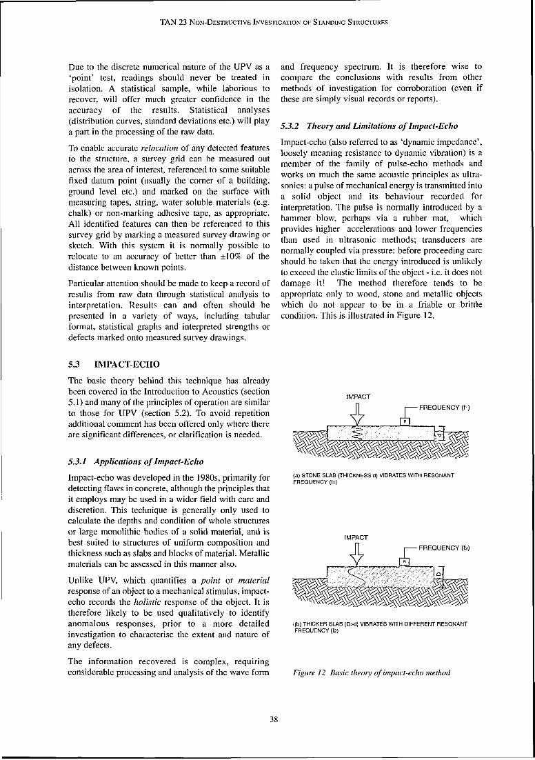
h
TAN 23 NON-DESTRUCTIVE INVESTIGATION OF STANDING STRUCTURES
Due to the discrete numerical nature of the UPV as a and frequency spectrum. It is therefore wise to 'point' test, readings should never be treated in compare the conclusions with results from other isolation. A statistical sample, while laborious to methods of investigation for corroboration (even if recover, will offer much greater confidence in the these are simply visual records or reports). accuracy of the results. Statistical analyses (distribution curves, standard deviations etc.) will play 5.3.2 Theory and Limitatiorzs of Impact-Echo a part in the processing of the raw data.
To enable accurate relocation of any detected features to the structure, a survey grid can be measured out across the area of interest, referenced to some suitable fixed datum point (usually the corner of a building, ground level etc.) and marked on the surface with measuring tapes, string, water soluble materials (e.g. chalk) or non-marking adhesive tape, as appropriate. All identified features can then be referenced to this survey grid by marking a measured survey drawing or sketch. With this system it is normally possible to relocate to an accuracy of better than +10% of the distance between known points.
Impact-echo (also referred to as 'dynamic impedance', loosely meaning resistance to dynamic vibration) is a member of the family of pulse-echo methods and works on much the same acoustic principles as ultra- sonics: a pulse of mechanical energy is transmitted into a solid object and its behaviour recorded for interpretation. The pulse is normally introduced by a hammer blow, perhaps via a rubber mat, which provides higher accelerations and lower frequencies than used in ultrasonic methods; transducers are normally coupled via pressure: before proceeding care should be taken that the energy introduced is unlikely to exceed the elastic limits of the object - i.e. it does not
Particular attention should be made to keep a record of damage it! The method therefore tends to be results from raw data through statistical analysis to appropriate only to wood, stone and metallic objects interpretation. Results can and often should be which do not appear to be in a friable or brittle presented in a variety of ways, including tabular condition. This is illustrated in Figure 12. format, statistical graphs and interpreted strengths or defects marked onto measured survey drawings.
5.3 IMPACT-ECHO
The basic theory behind this technique has already been covered in the Introduction to Acoustics (section
IMPACT 5.1) and many of the principles of operation are similar to those for UPV (section 5.2). To avoid repetition additional comment has been offered only where there are significant differences, or clarification is needed.
5.3.1 Applications of Impact-Echo
Impact-echo was developed in the 1980s, primarily for detecting flaws in concrete, although the principles that it employs may be used in a wider field with care and discretion. This technique is generally only used to calculate the depths and condition of whole structures or large monolithic bodies of a solid material, and is best suited to structures of uniform composition and thickness such as slabs and blocks of material. Metallic materials can be assessed in this manner also.
Unlike UPV, which quantifies a point or material response of an object to a mechanical stimulus, impact- echo records the holistic response of the object. It is therefore likely to be used qualitatively to identify anomalous responses, prior to a more detailed investigation to characterise the extent and nature of any defects.
The information recovered is complex, requiring considerable processing and analysis of the wave form
(a) STONE SLAB (THICKNESS d) VIBRATES WlTH RESONANT FREQUENCY (11)
IMPACT 6 g FREQUENCY ( f2)
~ ( b ) THICKER SLAB (D>d) VIBRATES WlTH DIFFERENT RESONANT FREQUENCY (h)
Figure 12 Basic theory of impact-echo method

TAN 23 NON-DESTRUCTIVE INVE~TIGATTON OF STANDING STRUCTURES
Plate cho
The different names for the method stem from the In practice this means that two apparently similar different parts of the process: structures (e.g. two stone columns) can have a different
the method used to excite the object, i.e. by transmitting a pulse of energy into it (generally a hammer is used - hence sometimes referred to as a 'bump' test)
the behaviour of the object (i.e. its mechanical impedance)
the characteristics of the mechanical wave and 'echo' or reflected wave form measured by the transducer.
The transmitted energy propagates through the object as a mechanical wave and causes it to vibrate. The characteristics of this vibration are dictated in part by the mechanical impedance of the object, which is affected by the condition and arrangement of its materials.
mechanical impedance for any one of the following reasons:
if their condition is different,
if the distribution of the materials within them is different, i.e. one of them is defective (e.g. cracked) or is constructed differently (e.g. has keyed or interlocking components)
if there are different 'boundary conditions.' (These refer to the environment the object is in, whether it is fixed to or in contact with another object or material. Thus differences in the impact-echo results will allow differentiation of a slab spanning a void from one that is supported along its length.)

TAN 23 NON-DESTRUCTIVE INVESTIGATION OF STANDING STRUCTURES
Wave Characteristics
Typically the mechanical wave measured has a fundamental frequency with a number of 'overtones'. The fundamental frequency has the greatest intensity while the overtones are frequencies of lower intensity that are simple multiples of the fundamental frequency. This is a direct parallel to sound: a musical note is rarely pure (i.e. a simple wave form of one frequency) and the presence of overtones give a note its characteristic quality or timbre.
The wave form recovered is complex and needs to be reduced to its constituent parts before analysis can commence, and causes are attributed to the behaviour of the object.
5.3.3 Impact-Echo Equipment
The equipment itself comprises:
a hammer or other means of 'bumping' the object to input energy (acting as the transmitter)
a receiver for measuring the object's response
a control box and signal processor
Typically the equipment is lightweight, rugged, portable and splash-proof. Instant hard copy printouts are obtainable if a portable printer is available (Plate 10).
An acrylic 'recoil-less' hammer is generally used. This ensures that enough energy is transmitted into the object to excite its natural frequencies. A metal hammer will sometimes bounce on impact, resulting in several energy "inputs" into the structure which will complicate readings. Such a hammer may also damage the object.
5.3.4 Impact-Echo Surveys
Operation is similar to the UPV equipment in that a receiver is placed on (and mechanically coupled via a high viscosity or thixotropic fluid to) the surface of the object. Generally it is placed close to and on the same surface as the point of impact (i.e. the hammer, acting as a transmitter). This is unlike UPV where it is preferable to have transmitter and receiver placed on opposite faces of the object.
At the beginning of the testing the equipment must be optimised and calibrated which will slow progress where a large number of objects are to be tested. Thereafter, data collection is essentially quick and discreet however.
The 'bump' required to transmit energy into the object will vary from object to object but data collection is non-destructive for robust materials such as stone, mortar, wood and concrete. More fragile materials such as plaster and ceramics are less suited to this method.

TAN 23 NON-DESTRUCTIVE INVESTIGATION OF STANDING STRUCTURES
6 PLANNING AN INVESTIGATION
This chapter considers contractual issues relevant to the successful specification and procurement of a non- destructive investigation by the conservation professional. Conservation professionals are strongly advised to ensure that only specialists familiar with the variety of non-destructive methods available and experienced in their application on similar projects are appointed to undertake an investigation.
6.1 Preparing for a Non-Destructive Investigation
6.1.1 Timing the Investigation
must be an analysis that is neither too broad, resulting in irrelevant detail, or too restrictive - pre-supposing the outcome of the investigation. It is important to bear in mind that an investigation is being specified and not a test. It is wise for the specification to avoid being overly definitive so that the investigator can recommend alternative or additional techniques as appropriate. The investigator should also be expected to recommend and develop methodologies in consultation with architects, engineers, surveyors, archaeologists and other conservation experts. The investigator's ability to produce and communicate a unique methodology is one of the key indicators of the quality of any proposal.
A typical programme for conservation work organised Careful consideration of the following points can help and managed by the conservation professional to define effectively the scope of an investigation: comprises five distinct phases:
overall project constraints, objectives and 1. inspection of object or structure timetable.
2. structural assessment the reasons for which a non-destructive
3. specification of repairslactions investigation is being considered - missing information, gaps in the structural record, any
4. costing of repairslactions as part of an economic poorly understood material or structural defect, assessment failure mechanisms etc. Often it will be necessary
5. implementation of the conservation works to assess the importance/significance of the missing information and set this against the costs -
A non-destructive investigation can contribute of the investigation. information to the first three phases and is optimally
the type of information required - this could relate placed close to the beginning of the project. The range
to quantity, location, orientation, condition etc. - of information that can be expected from a non-
and preferred presentation format (verbal, destructive investigation is discussed in more detail in
drawings, digital files, software compatibility etc.) Chapter 2. The investigation can recover a wide range of data which will provide the conservation the physical extent and location of key areas from professional with information that will aid decisions on which data will be recovered - note that this may consequent actions, and the investigation may be determined by access constraints, although at therefore sit on the project's critical path. Time must all times a statistically significant set of data is be allowed for the 'raw' data to be analysed or required. processed before the information required for the
the value of the information being sought. This can assessment of the structure or object can be presented.
be particularly helpful in assessing budget considerations, on occasion a marginal increase in
6.1.2 Defining the Scope of the Investigation budget might offer a long term gain.
To define effectively the scope of an investigation subsequent processes for which the information involving new or unfamiliar technology the may be required, including the potential re-use of conservation professional needs to develop a clear and the information, as part of an archive, in other realistic expectation of the assessment process and its areas of the structure etc. results.
Note that it is good practice for the investigator to A brief must be generated that is wide ranging but collect some data from a 'control' area similar to, but offers specific guidance to the investigator - the result
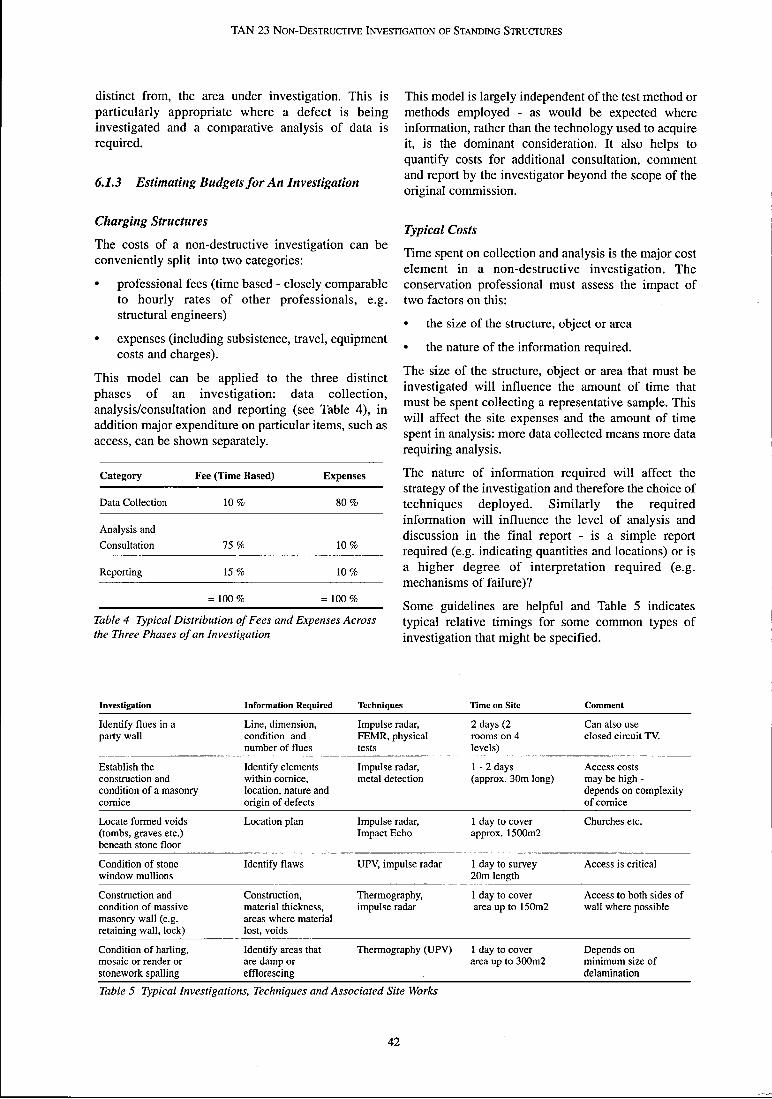
TAN 23 NON-DESTRUCTIVE INVESTIGATION OF STANDING STRUCTURES
distinct from, the area under investigation. This is This model is largely independent of the test method or particularly appropriate where a defect is being methods employed - as would be expected where investigated and a comparative analysis of data is information, rather than the technology used to acquire required. it, is the dominant consideration. It also helps to
quantify costs for additional consultation, comment
6.1.3 Estimating Budgets for An Investigation and report by the investigator beyond the scope of the original commission.
Charging Structures Typical Costs
The costs of a non-destructive investigation can be Time spent on collection and analysis is the major cost conveniently split into two categories: element in a non-destructive investigation. The
professional fees (time based - closely comparable conservation professional must assess the impact of to hourly rates of other professionals, e.g. two factors on this: structural engineers)
the size of the structure, object or area expenses (including subsistence, travel, equipment .
the nature of the information required. costs and charges).
This model can be applied to the three distinct The size of the structure, object or area that must be investigated will influence the amount of time that phases of an investigation: data collection, must be spent collecting a representative sample. This analysis/consultation and reporting (see Table 4), in will affect the site expenses and the amount of time addition major expenditure on particular items, such as spent in analysis: more data collected means more data access, can be shown separately. requiring analysis.
Category Fee (Time Based) E~~~~~~~ The nature of information required will affect the strategy of the investigation and therefore the choice of
Data Collection 10 % 80 % techniques deployed. Similarly the required information will influence the level of analysis and
Analysis and discussion in the final report - is a simple report Consultation 75 % 10 % required (e.g. indicating quantities and locations) or is
Reporting 15 % 10 % a higher degree of interpretation required (e.g. mechanisms of failure)?
= 100 % = l o o % Some guidelines are helpful and Table 5 indicates
Table 4 Typical Distribution of Fees and Expenses Across typical relative timings for some common types of the Three Phases of an Investigation investigation that might be specified.
Investigation Information Required Techniques Time on Site Comment
Identify flues in a Line, dimension, Impulse radar, 2 days (2 Can also use party wall condition and FEMR, physical rooms on 4 closed circuit TV.
number of flues tests levels)
Establish the Identify elements Impulse radar, 1 - 2 days Access costs construction and within cornice, metal detection (approx. 30m long) may be high - condition of a masonry location, nature and depends on complexity cornice origin of defects of cornice
Locate formed voids Location plan Impulse radar, 1 day to cover Churches etc. (tombs, graves etc.) Impact Echo approx. 15001112 beneath stone floor
Condition of stone Identify flaws UPV, impulse radar 1 day to survey Access is critical window mullions 20m length
Construction and Construction, Thermography, 1 day to cover Access to both sides of condition of massive material thickness, impulse radar area up to 1501112 wall where possible masonry wall (e.g. areas where material retaining wall, lock) lost, voids
Condition of harling, Identify areas that Thermography (UPV) 1 day to cover Depends on mosaic or render or are damp or area up to 3Wm2 minimum size of stonework spalling efflorescing delamination
Table 5 Typical Investigations, Techniques and Associated Site Works
42

TAN 23 NON-DESTRUCTIVE INVESTIGATION OF STANDING STRUCTURES
Equipment hire is an additional factor sometimes mandatory but is usual amongst reputable and included in the costing of different tests. The capital established providers of equipment, testing, cost of equipment is high and facilities exist to rent investigation or consultancy services. complex equipment on an ad hoc basis. This becomes
Having compiled a list of two or three suitable a consideration for the conservation professional if investigators for the work, a quotation for works timing of the investigation works is critical, or specific
should be requested. This should be in the form of a equipment guidelines and configurations are
technical proposal accompanied by a financial designated by the investigator (e.g. long wave
proposal. thermography vs. short wave thermography, certain frequencies of transducer).
Contract Structures The timings quoted should be used as rough guides only - each investigation and object will require The ideal contract structure should encourage a individual consideration. relationship between the conservation professional and
investigator where the expertise of the investigator can
6.1.4 Selecting arz Investigator
The value of non-destructive investigations is recognised across a wide range of fields. However, care should be taken by conservation professionals to distinguish between the following:
providers of non-destructive test equipment (manufacturers and hire companies)
operators of non-destructive test equipment
consultants who use non-destructive test methods within the context of an investigation -,and their field of expertise (archaeologicallground investigations, modern structures, historic structures, conservation work etc.)
The distinction between operators and consultants is frequently blurred in this developing field. Checks made against the following points will help ensure a reliable assessment of competence:
be brought to bear on t h e problem at hand, fully informed and guided by the conservation professional.
Discussion should occur at all stages of the investigation: in determining recommendations for appropriate methods, their deployment, the interpretation/collation of data and presentation of findings. For example, an appropriate, bespoke methodology can be developed during a preliminary discussion of the problem. It will often be necessary to make allowance for trials and calibration, and agree details of alternative methods andfor a mechanism for handling variations arising from the unsuccessful application of any one method. The sequential nature of a non-destructive investigation often requires that preliminary results influence selection and deployment of subsequent investigation methods. This is not entirely open ended or without definition and the investigator can be expected to discuss possible scenarios dependant on the outcome of preliminary testing. -
The number of staff and their experience in this The use of highly prescriptive procurement methods
type of work such as a Bill of Quantities in providing a cost per unit
Involvement in similar previous projects area is rarely appropriate except where the commission (structurelobject and material type, client, type of is a large, test-based investigation, dominated by data investigation, findings and cost) collection costs (site works, the number of tests
deployed, sample frequency etc.). These tests typically Client references
involve the use of relatively simple equipment and Quality Assured management systems for instrumentation and require a low level of collection and analysis of data, project interpretation on site prior to collation and analysis. management etc.
Relevant NAMAS standards (National 6.1.5 Elements required in a Quotation for Work Accreditation of Measurement and Sampling) for
Following an initial briefing in which the full available equipment calibration.
information is laid out, the investigator should be In this developing field, professional accreditation is required to produce a detailed technical proposal which not always practical or relevant - unless it is to an sets out: affiliated discipline (such as structural engineering).
how the investigation will be structured Some specialised and self-regulatory bodies have been formed within the field such as The British Institute of what methods will be used and why they have been Non-Destructive Testing. Membership of the various selected bodies and adherence to their codes of conduct is not
g what their limitations are
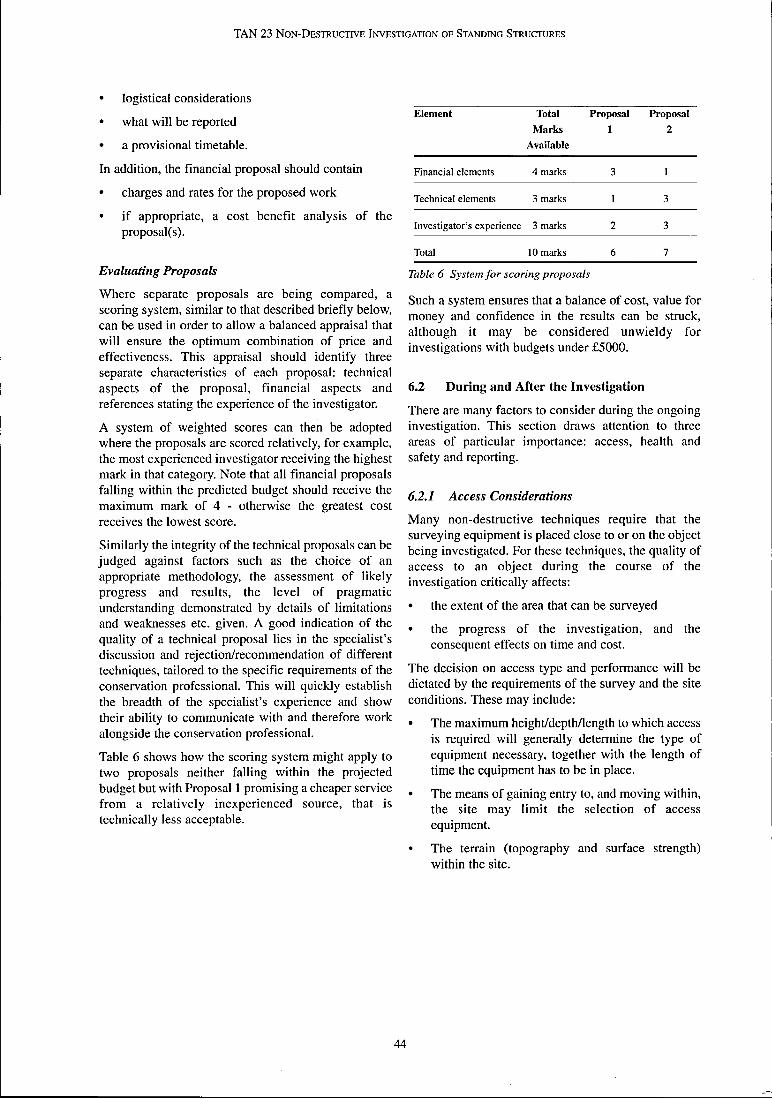
TAN 23 NON-DESTRUCTIVE INVESTIGATION OF STANDING S T R U ~ R E S
logistical considerations
what will be reported
a provisional timetable.
In addition, the financial proposal should contain
charges and rates for the proposed work
if appropriate, a cost benefit analysis of the proposal(s).
Evaluating Proposals
Where separate proposals are being compared, a scoring system, similar to that described briefly below, can be used in order to allow a balanced appraisal that will ensure the optimum combination of price and effectiveness. This appraisal should identify three separate characteristics of each proposal: technical aspects of the proposal, financial aspects and references stating the experience of the investigator.
A system of weighted scores can then be adopted where the proposals are scored relatively, for example, the most experienced investigator receiving the highest mark in that category. Note that all financial proposals falling within the predicted budget should receive the maximum mark of 4 - otherwise the greatest cost receives the lowest score.
Similarly the integrity of the technical proposals can be judged against factors such as the choice of an appropriate methodology, the assessment of likely progress and results, the level of pragmatic understanding demonstrated by details of limitations and weaknesses etc. given. A good indication of the quality of a technical proposal lies in the specialist's discussion and rejection/recommendation of different techniques, tailored to the specific requirements of the conservation professional. This will quickly establish the breadth of the specialist's experience and show their ability to communicate with and therefore work alongside the conservation professional.
Table 6 shows how the scoring system might apply to two proposals neither falling within the projected budget but with Proposal 1 promising a cheaper service from a relatively inexperienced source, that is technically less acceptable.
Element Total Proposal Proposal
Marks 1 2 Available
Financial elements 4 marks 3 1
Technical elements 3 marks 1 3
Investigator's experience 3 marks 2 3
Total 10 marks 6 7
Table 6 System for scoring proposals
Such a system ensures that a balance of cost, value for money and confidence in the results can be struck, although it may be considered unwieldy for investigations with budgets under £5000.
6.2 During and After the Investigation
There are many factors to consider during the ongoing investigation. This section draws attention to three areas of particular importance: access, health and safety and reporting.
6.2.1 Access Considerations
Many non-destructive techniques require that the surveying equipment is placed close to or on the object being investigated. For these techniques, the quality of access to an object during the course of the investigation critically affects:
the extent of the area that can be suneyed
the progress of the investigation, and the consequent effects on time and cost.
The decision on access type and performance will be dictated by the requirements of the survey and the site conditions. These may include:
The maximum heightldeptmength to which access is required will generally determine the type of equipment necessary, together with the length of time the equipment has to be in place.
The means of gaining entry to, and moving within, the site may limit the selection of access equipment.
The terrain (topography and surface strength) within the site.

TAN 23 NON-DESTRUCTIVE INVESTIGATION OF STANDING S T R U ~ S
This checklist should identify most common dangers - gravel borders, flowerbeds, ornamental gardens or decorative lawns adjacent to external walls. Note that larger machinery can have high axle loads and should not be located over cellars etc. or close to basements, embankments etc. Ladders similarly can exert high point loads.
Access Methods
Access is needed in a wide variety of situations: working at height, working over or near to water, in confined spaces, below ground, on or near to public highways etc. These and other scenarios are discussed briefly in the next section on Health and Safety, however the most common situation encountered when inspecting or surveying buildings is working at height.
Various methods of reaching a point above ground or floor level on a building are available and the cost of each should be weighed against the risk of restricting the information gathered, in all cases it will be necessary to ensure the safety of operators or bystanders.
FullJixed scaffolding Full fixed scaffolding properly erected with platforms every 2.5 metres usually provides the safest and most effective access to the majority of structures. It can be costly, however, and is therefore normally an option only when other works are planned. Temporary scaffold towers ('Zip-Up' type) provide a reasonable alternative for access to no more than three storeys.
Suspended Access Platfrms Suspended access platforms provide a simple, convenient and rapid means of accessing the face of a building, provided that the face is vertical with no projections: they can be readily erected and moved, but need a competent scaffold erector on site to do this, which adds to their cost.
As a rule of thumb, an articulated hoist should always have at least 15 - 20% greater reach than that assumed to be needed for the survey. For access to small areas a scissor-type platform with a relatively large platform area may be sufficient, but for larger areas a platform mounted on the end of a telescopic hydraulic arm normally provides the most effective means of gaining access.
Ladders Ladders are a cheap access system, offering hand access to a small area. However, the temptation to overreach is great and can easily lead to toppling, especially if the ladder cannot be tied securely, or where the ladder is moved frequently. They may be appropriate if only a small area is to be inspected, however.
Powered Access Platfrms Powered access platforms are available in two main types: scissor types which extend vertically upwards and hydraulic arm or 'cheny picker' type platforms, comprising a bucket or platform at the end of a telescopic, articulated hydraulic arm. Both types can be deployed rapidly. In general, survey coverage is slower than with fixed scaffold but the overall cost saving can be significant because of the cheaper access equipment rental charges. These platforms allow highly flexible access, ideal for surveying complex forms. They are heavy however (to maintain stability) so careful consideration must be given to positioning the vehicle. Examples of the use of powered access platforms for two different investigations are shown in Plates 1 and 11.
rib"
Plate 11 Photograph of survey being carried out from hydraulic hoist

TAN 23 NON-DESTRU~IVE INVE~TIGATION OF STANDING STRUCTURES
6.2.2 Health & Safety sites beneath overhead workings
sites adjacent tolon public highways Legislation
sites in close proximity to high voltage cables. The Management of Health & Safety at Work Regulations 1992, together with the Construction Extensive literature is available offering advice on
(Health, Safety & Welfare) Regulations 1996, and dealing with the specific and general risks of working in these and other environments. The following subsequent amendments and updates, place a comments address the health and safety considerations requirement on both employers and the self employed
to make and maintain a sufficient and suitable risk of working with access equipment. They are not
assessment, such that they take at all times the intended to replace official guidelines, with which conservation professionals should familiarise measures necessary to comply with Health & Safety
law. themselves. Additional health and safety considerations for working with particular non-
It is taken throughout as an absolute that this will be destructive methods are included in the relevant done, and that the conservation professionals involved chapters of this advice note. in the assessment of historic structures are already well acquainted with these measures, and their application to their tasks. Safe Working with Access Equipment
Reference should be made to the HSE sheets referred This document is an inappropriate medium to provide
to in the text. instruction on this, and general comments only are given: any professionals unacquainted with the Where access equipment is used it must be: provisions are advised to obtain further advice and information from local offices of the Health and Safety clean and fully operative
Executive (HSE). well maintained and with relevant certification
used in the manner intended by its designers. General
Trained operatives should be responsible for The nature and severity of risks presented at a site vary installation and operation of all types of mechanical widely. The conservation professional should be able access equipment although some access equipment is to provide the investigator with information on all operated by the hirer. In these instances, training must hazards prior to preparation of a proposal so that plans be provided by the hire company. The user of the can be made to minimise the risk to the health and equipment should also read any literature, warning safety of the investigation team, other people in the signs and labels supplied with or affixed to the vicinity of the site and the general public. Similarly the equipment. conservation professional should expect the investigator to provide a health and safety policy as a When using scaffolding, it is of primary importance to
part of their technical proposals, demonstrating an ensure the stability of the construction. The stability of
awareness of the risks posed by the site, and by the a scaffold will be affected by the way it is used, and it
proposed methods of working, and describing is important that the right sort of scaffold is erected for
measures for mitigating them. the intended work. There should be means of protecting bypassers from falling materials and equipment and means of restraint to prevent
Risk Assessments individuals working on the scaffold from falling off it.
All sites should be subject to a general risk assessment. The scaffold must be inspected before use and
Where this reveals a need for specialist training, inspections carried out by a competent person at
certification or experience then this must be allowed intervals not exceeding seven days and the results
for in the programme and budget of the project. recorded in a Register. Only competent scaffolders
Potentially hazardous work environments include: should erect, alter or dismantle scaffolds. Before erecting a scaffold on a public highway the appropriate
building sites highway authority must be contacted and permission
working in or near open excavations obtained.
working at height Details and guidelines on the safe use of scaffolds can be found in HSE Information Sheet General Access
tidal zones and sites adjacent to or over water Scaffolds and Ladders, Construction Sheet No. 49 and
closedlconfined spaces HSE Information Sheet Tower Scaffolds, Construction Sheet No. 10 (revision 3).
46
TAN 23 NON-DESTRUCTIVE INVESTIGATION OF STANDING STRUCTURES
Ladders are primarily a means of gaining access to a workplace; they can also be used as working platforms in their own right for work of short duration for which they have been assessed as suitable. However the need, common to many NDT methods, to cany equipment, accommodate trailing cables etc. means that ladders are unlikely to provide a safe working platform in many cases. If work is to be carried out from a ladder then it must be properly secured and the correct grade used.
should also be considered at the outset and standards for presentation and format decided. It is inappropriate to present results exclusively in technical terms or as simple numerical data. The information presented should be unambiguous and reveal a clear line of reasoning between the raw data and the conclusions drawn. Factual and interpretative conclusions should be clearly identified at all times - note that raw data from non-destructive tests is not usually presented within the final report.
Results are often presented through graphical means, 6.2.3 Analysis and Reporting either as graphs or sketches, photographs, sections,
plans and elevations. The quality of the drawings provided can vary from a simple hand-drawn sketch to
Analysis detailed scale drawings produced to a pre-agreed
Interim or draft reports may be reasonably expected standard on a CAD system, depending on the specific during the course of an investigation or even, requirements and budget of the client. exceptionally, on site. Discrete sections of data cannot usually be analysed in isolation, but frequently require the context of the whole data set, including any control data, for a confident interpretation. It is important in planning the investigation that a realistic time frame is agreed for the proper interpretation and analysis of any results - premature interpretation often relies primarily on experience from similar sites, rather than the specific test results obtained in the current investigation.
Measured Sunteys
The accurate recording of the results of a non- destructive investigation will be assisted if measured survey information can be made available in advance as results can be overlaid directly onto the measured survey. If accurate survey drawings of the structure already exist in a CAD (computer aided design) format the provision of these drawings, on a computer disk (in a compatible format) will save time and improve the accuracy of the presentation of results from the Presentation of Results investigation.
The nature of the information required at different stages and any preferred or required presentation formats should be discussed. Archive requirements
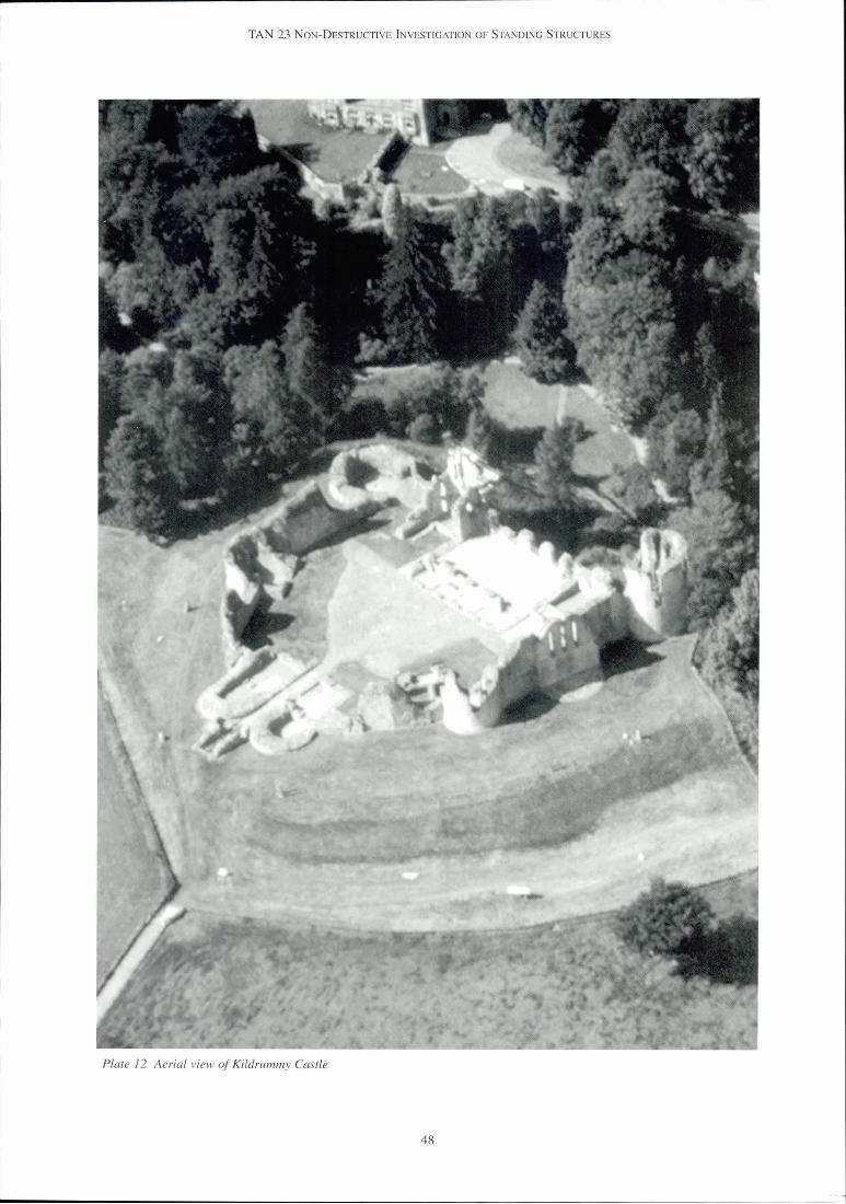
Plate 12 Aerial view of Kildrummy Castle

TAN 23 NON-DESTRUCTIVE INVESTIGATION OF STANDING STRUCTURES
7 CASE STUDY KILDRUMMY CASTLE
7.1 Purpose of the Investigation
This ruined thirteenth century fortress-residence was restored and partially reconstructed around 1900.
In 1991 a facing stone came away during raking out and repointing. The stone appeared sound and hard, but had been face-bedded, and had split on the bed approximately lOOmm from the front face. Its rear tail had decayed and reverted to sand. The exposed wall core was completely saturated. It is likely that the impermeable cementitious mortar used in the 1900 work had trapped moisture in the walls, leading to saturation of the rubble-filled medieval cores, dissolution of the bonding matrix and loss of structural integrity.
At this stage (December 1991) the remedial action mooted included the provision of weep holes (to allow the water in the core to drain out) and a french drain. Grouting and other structural measures might follow if required. Investigation of the wall conditions by the drillingltaking of cores was suggested. The extent and seriousness of the problems required to be ascertained and the most appropriate forms of remedial action determined.
On consideration, core borings were thought too destructive, so an initial investigation using a non- destructive method was seen as appropriate. This work was also viewed as a pilot project to explore the use of non-destructive methods of investigating building problems. Electro-magnetic methods were being developed at that time for use on structures, and impulse radar in particular appeared to give promising results, providing useful information on a wide range of aspects (such as indicating different materials concealed within the structure and their condition, and the presence of voids or metallic objects).
The presence of the brief was to provide detailed and comprehensive information on the structure and condition of the walls, including the nature and dimensions of the construction materials, the locations of cavities or cracks within the walls, the location and condition of any metallic ties, and information on the moisture contents of the materials and the movement of water through the structure.
7.2 Details of the investigation
The investigative method chosen was impulse radar (an electro-magnetic method; see section 3.1), because it could give information on a number of factors, quickly and without any physical impact on the castle fabric.
The budget (in 199415) resulted from agreement on what constituted a reasonable scope of work, giving enough information to be useful both to inform conservation policy for the monument and to provide a case study for this TAN. Travel and subsistence, survey work and writing uplreporting elements were allowed for in the estimates.
The selection of an investigator: the use of impulse radar for building investigations is a highly specialised field, in which there are very few experienced contractors. Approaches were initially made to three organisations in order to assess their suitability, but ultimately the most experienced company in the field was chosen despite its higher fee, because it was the only one judged to satisfy the criteria of having sufficient experience and an extensive database for comparative purposes.
Timing was not critical, except that co-ordination with the regional staff was required as they were to provide access to the areas included in the survey. A pre-survey meeting was held on site to agree the sample areas and method of access to the walls. As impulse radar requires close contact with the surfaces being monitored, temporary scaffolding towers (complying with CDM regulations) were decided on.
The survey ( l and 2 March 1995): two days were spent surveying four locations (the maximum number possible in this time). The size of each survey area resulted from the wall configuration and the scaffold provided. Data was collected from a grid at 500mm centres vertically and Im horizontally.

TAN 23 NON-DESTRUCTIVE INVESTIGATION OF STANDING STRUCTURES
Figure 13 Elevation of chapel gable (north-east wall), Kildrummy Castle
7.3 Conclusions of the Investigation
The cementitious pointing (which remains everywhere but on the north-west curtain wall) has been drilled into by Historic Scotland masons, the object being to see if it could be removed in order to replace it with a lime mortar, and any voids filled. However the hard pointing proved to be at least 150mm deep, and it was felt that any attempt to remove it would be likely to cause more damage to the stonework than leaving it in place. The surface of the pointing was scabbled back so that the mortar is now recessed within the joints and stone decay is minimised.
The Historic Scotland engineer was consulted on whether remedial works were needed to the walls in light of the decayed core. His advice was that in the short term, since there was no surface evidence of strain (cracks and movement in the stonework face) it could be safely left, and that the two skins of stonework were probably thick enough and strong enough to contain the core in a stable position despite its condition.
However, in the longer term, based on the evidence of Specific information was obtained on the widespread dampness and decay in the wall cores, he
construction of the walls; thickness of the facing stones suggested that monitoring should be initiated, (generally 200 to 350mm), mortared nature of the and follow-up repair works considered. The rubble infill, etc. monitoring would include removal of facing stones in
A generally high moisture content was found in the two or three selected areas (where the worst voids had walls, especially deep in the walls (the further from the been found) to inspect the core, and also a programme surface, the higher the moisture level). of monitoring the moisture content using probes, over
Poor contact and voids in walls were located (giving routes for water penetration), which were extensive, particularly in the north-west curtain wall. Vertical joints were reasonably tight. A large void showed at the base of the Warden's tower, which may prove to be either a cavity, or an actual chamber.
New lime pointing (north-west curtain wall, 1990s) showed confusing results, the reasons not being clear.
a period of two to three years. In addition there was a concern that there could be movement in the Warden's tower and this should be monitored and recorded. Weep holes should be provided along the base of the north-west wall where it acts as a retaining wall. Following the monitoring process, consideration could be given as to whether works of grouting or stitching would be appropriate, and expert advice sought on the methods to be adopted.
No evidence of metallic fixings was found. 7.5 Considerations on the use of impulse radar
Specific Recommendations:
that the void at the base of the Warden's tower should be investigated further; and
that a re-examination of the walls in the summer, when moisture levels were reduced, might give better penetration by impulse radar.
7.4 Subsequent conservation at Kildrummy Castle
Since the initial impulse radar survey was carried out, there has been no further impulse radar investigation. The possible chamber discovered by the investigation in the base of the Warden's tower has been left undisturbed.
In the case of Kildrummy Castle, this investigation turned out to be relatively expensive for the amount of information obtained. It had already been established that the core was damp, and that it had broken down and shifted in places, and that the backs of some stones were decayed. What was needed was further information on whether this was an isolated case or spread throughout the castle, and whether the problem was worse or better elsewhere. Because the cost prohibited a full survey, it was not possible to get a complete picture of the wall conditions, but a range of areas was sampled and the defects proved to occur in each of these, indicating that they probably occurred throughout.

-
TAN 23 NON-DESTRUCTIVE INVESTIGATION OF STANDING STRUCTURES
The excessive humidity of the core and its mortared rubble character were confirmed by the investigation and it was clear that there were many voids behind the surface stonework. But the high moisture content of the core blocked the return of more information. Examination of moisture movement would have required additional surveys for which there was no budget.
However, the investigation carried out at Kildrummy Castle caused no damage to the fabric of the monument and retrieved some very useful information on the condition of its internal structure. The general depth of the surface skin of stonework was measured, and the nature of the rubble in the core (where it registered) and the lack of metal cramps were noted. These factors informed the engineer's assessment of the stability of the walls and his recommendations on further action.
Plate 13 Repair works at Kildrummy Castle in the early twentieth century.
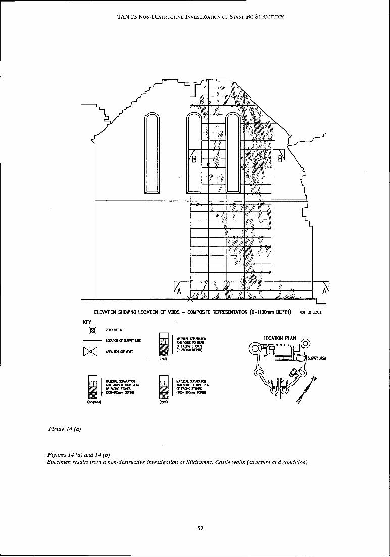
TAN 23 NON-DESTRU~IVE INVESTIGATION OF STANDING STRUCTURES
W A T I O N SHOHNG LOCATION OF WDS - COMPOSITE REPWSOYTAmON ( O - l l ~ m DEPTH) NOT TO S W
KEY $I WOMTUI
Figure 14 (a)
Figures 14 (a) and 14 (b) Specimen results from a non-destructive investigation of Kildrummy Castle walls (structure and condition)
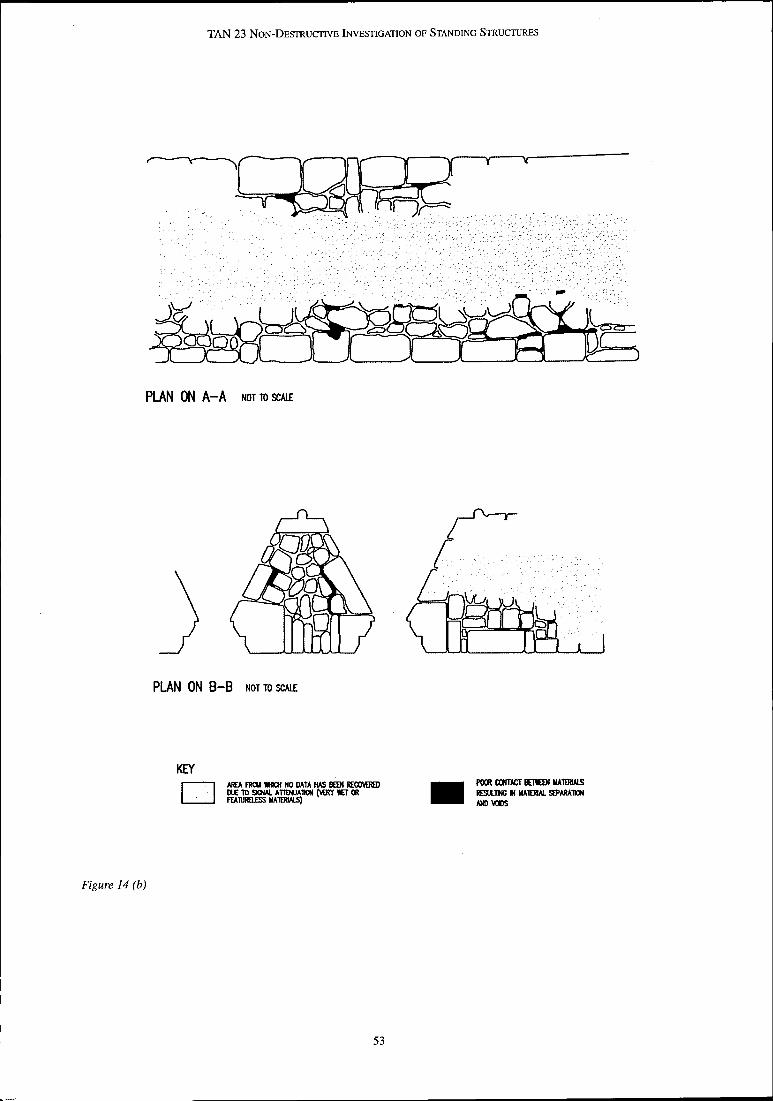
TAN 23 NON-DESTRUCTIVE INVESTIGATION OF STANDING STRUCTURES
L-
PLAN ON B-B NOT TO SW
KEY AREA FRCY W NO DATA W US POORCCHTACTBnrWMATOMLS
m m
Figure 14 (b)

TAN 23 NON-DESTRUCTIVE INVESTIGATION OF STANDING STRUCTURES
8 BIBLIOGRAPHY
The following texts offer a variety of general and specific information for the interested reader.
General
Lorrain P, Corson D R, 1979, Electromagnetism: Principles and Applications
Duffin W J, 1965, Electricity and Magnetism
Kaye G W C, Laby T H, 1973, Tables of Physical and Chemical Constants
Fidler J, JuneJJuly 1985, Clerk of Works, Modem Technology in Conservation: Non-Destructive Survey Techniques for the Analysis of Historic Buildings
Ferretti M, 1993, Scientific Investigations of works of Art. ICCROM
Impulse Radar
Acoustics
CNS Electronics Ltd, Portable Ultrasonic Non- Destructive Digital Indicating Tester (PUNDIT)
Various papers and authors, 1993, Concrete Civil Structures, Proceedings of Fifth International Conference on Structural Faults and Repair
Health & Safety
Various information sheets are available from the Health & Safety Executive which cover various aspects of safe working environments and access in some depth, including:
General Access Scaffolds and Ladders, HSE Construction Sheet No. 49 - safe use of scaffolds and ladders
Tower Scaffolds Construction, HSE Information Sheet No. 10 (revision 3) - safe use of tower scaffolds
Concrete Society, Technical Report No 48, 1997, Construction (Health, Safety and Welfare) Regulations Guidance on Radar Testing of Concrete Structures
1996
Thermography
Smith A J R, 1994, An Introduction to Industrial Thermography
FLIR Systems Inc., 1991, Infrared Imaging Guide
Electro-magnetic Metal Detection
Protovale Ltd, various technical papers
Free Electro-Magnetic Radiation
Radiodetection Ltd, 1986, The Theory of Buried Pipe and Cable Location
Health and Safety at Work etc. Act I974 - general references to legislation
Management of Health and Safety at Work Regulations, 1992
Provision and Use of Work Equipment Regulations I992
Manual Handling Operations Regulations, I992
Ionising Radiations Regulations (this document is currently being updated.
Additional advice and information can be obtained from local offices of the Health and Safety Executive which provides up-to-date information sheets and guidance for safe working practices.

1 TAN 23 NON-DESTRUCTIVE INVESTIGATION OF STANDING STRUCTURES
9 GLOSSARY
The purpose of this glossary is to provide a brief explanation of some of the technical terms commonly encountered when describing and using Non Destructive Investigative techniques: the list is not exhaustive, but covers most of the terms contained within the Technical Advice Note. The object is to be useful rather than to provide definitive text book explanations.
instrumentation system from the smallest signal resolvable above the system noise to the largest signal the system can handle.
Eddy Current The current induced in a mass of conducting material by a varying magnetic field.
AntennaIAeriayTransducer Converts the driving power into a radiated signal, and converts signals returned from the material investigated into electrical information.
Effective Radiated Power The total radiated power of an aerial.
Emissivity The amount of internal energy that is emitted by an object.
Antenna efficiency The extent to which an aerial converts the driving FEMR power into radiated energy. Free Electromagnetic Radiation (see Chapter 3).
Attenuation Filter A general term for the reduction in magnitude, Any system that preferentially passes signals within amplitude or intensity of a physical quantity, arising certain frequency ranges whilst suppressing those in from absorption, scattering or geometrical dispersion. others. Soil acts as a Low-Pass Filter, suppressing
higher frequency signals. Clutter Unwanted signals, for example on a radar system, that GPR are caused by extraneous signals or echoes. Ground ProbingPenetrating Radar.
Coupling factor A measure of the extent of energy transfer from one system or material into another.
DecibeYdB A dimensionless unit used to express the ratio of two powers. Often associated with volume or signal amplitude.
Dielectric Any material that can sustain an electric field and is a
GPRIImpulse Radar Generic terms identifying types of low power systems used for echo sounding. GPR is commonly used as the systems were first developed for penetrating the ground, whereas Impulse Radar describes the way in which the sounding system operates.
Systems which transmit a low energy electromagnetic pulse at radio frequencies into solids and collect the reflected signals for subsequent processing and manipulation (See Chapter 3).
good insulator - dielectrics contain no free charges but Impulse the material may be polarised at molecular or
A unidirectional disturbance that rises rapidly to a microscopic levels.
maximum and dies away smoothly (without significant oscillations) to zero.
Directional aerial An aerial that is a more effective transmitter or receiver Jitter of energy in certain directions. Timing noise in the composition of the signal in the
sampler. Dynamic Range The range, normally expressed in decibels (dB), over NDI which useful information can be recovered from an Non-Destructive Investigation.

TAN 23 NON-DESTRUCTIVE INVESTIGATION OF STANDING STRUCTURES
Periodicity The time taken for an oscillating object to complete one complete cycle.
Plane Polarisation Oscillations which are in a single plane are described as plane polarised.
Pulse A single transient disturbance, or one of a regular series of such disturbances.
Pulse Repetition Frequency The frequency at which pulses are sent to the aerial for transmission.
Radiation Loss The natural drop in received power as a receiving antenna of fixed size is moved away from the transmitter.
Radiation Pattern A diagram showing the spatial distribution of energy from a transmitting aerial - often showing a complicated three dimensional 'lobed' structure.
Reflection Coefficient When an electro-magnetic wave reaches any boundary between two transmissive media, it undergoes partial reflection - thus the reflection coefficient describes the ratio of the reflected energy to the incident energy.
Reflectivity The amount of external energy that is reflected rather than absorbed by an object.
Relative Permittivity A measure of the ease with which materials allow charges to polarise under the influence of an applied electric field: the ratio of the capacitance of a particular dielectric material of defined dimensions, to that of a vacuum of the same dimensions. Also referred to as Dielectric Constant.
Sampler That part of the receiver system which converts the radio frequency signals recovered by the antennae into a low frequency electronically representation that can be processed. This is normally an analogue stage.
Scabbled Roughly faced with a pick, chisel or hammer.
Signal to noise ratio A measure of the quality of the received data: the ratio of the signal power to noise power at the point of observation, measured in dB. A signal processing and recording system may have a good signal to noise ratio, but if the overall ratio falls too low (e.g. the antenna is 'noisy'), any useful information is lost in background signals.
Spectrum The full range of the electro-magnetic spectrum covering all radiation including microwaves and visible light. With a lower case 'S', it refers to the range of frequencies in a given signal or time series.
SW Short Wavelength. The band of wavelengths in the electromagnetic spectrum from 3 to 5.50m.
Target Any object that is being investigated.
Target Characteristics Simplistically, these are the size and dielectric properties of the target. In practice, the dielectric contrast and nature of the boundary between the target and its surroundings will also have a significant effect.
Transmission Loss The loss of signal power along the wave path due to dissipation, partial reflection at boundaries and scatter from objects contained within a medium.
Transmissivity The rate at which energy can be transmitted through an object: in thermography, the ability of a material to sustain a heat flow.
Travel Time The time taken for a radiated pulse to travel between two points: two way travel is the time taken for a pulse to travel from an antenna to a reflective surface and back again.
UPV Ultrasonic Pulse Velocity (see Chapter 5)
Velocity The speed at which a wave group travels through a dielectric medium, which is constant provided the electrical properties of that medium do not change.

TAN 23 NON-DESTRUCTIVE INVESTIGATION OF STANDING STRUCTURES
10 USEFUL ADDRESSES
The following organisations, referred to in the main body of the advice note, may be contacted for further information. Addresses are correct at time of publication.
British Institute of Non Destructive Testing Health & Safety Executive 1 Spencer Parade Belford House Northampton 59 Belford Road NNl 5AA Edinburgh Tel No: 01604 630124 EH4 3UE Fax No: 01604 23 1489 Tel: 0 13 1 247 2000 Email: [email protected] Fax: 0131 247 2121
UKAS (United Kingdom Accreditation Service) NAMAS (See details for UKAS) 21 - 47 High Street Fe1 tham Middlesex TW13 4UN Tel: 0181 917 8400 Fax: 0181 917 8499
Euro GPR (Formerly Impulse Radar Users Association) PO Box 1381 Rugby Warwickshire CV21 2ZF Tel: 01788 536389 Fax: 01788 550152 Email: [email protected]

TAN 23 NON-DESTRUCIWE INVESTIGATION OF STANDING STRUCTURES