tailored optical fibres - desytesla.desy.de/~elhep/home/rrom/tailored.optical.fibers.pdf ·...
TRANSCRIPT

Tailored optical fibres
Ryszard S. Romaniuk
ISE, Warsaw University of Technology [email protected]
ABSTRACT
The paper defines the field of special optical fibers. Classification of tailored optical fibers was introduced. The characteristics of main families of such fibers were presented. There were discussed the following fibers: isotropic made of soft glass, of complex refraction – including ring-index, polarization maintaining and polarizing, elliptical, holey with macro holes and porous, nonlinear, active, high power, Bragg, tapered, plastic, technologically sensitized, multicore and infrared.
Keywords: Optical fibre technology, specialty optical fibres, customized optical fibres,
1. INTRODUCTION Optical fiber technology can be divided into two major fields – opto-telecommunication and fiber optics of specialty non-communication fibers. Optical fiber communications (OFC) investigates new generations of ultra-low-loss, linear, isotropic and broadband dispersion compensated, transmission fibers for DWDM technology (spanning from S, through C to L and XL optical bands). The OFC uses optimization technologies for current, more efficient usage of older fibers installed several years ago [1]. Optical fibers for applications outside the trunk transmission field are called specialty or tailored ones [2,3]. The latter fibers are used in optical communication as short-length, functional photonic components. They are also used in photonic systems for information processing and hybrid optoelectronic ICs [4] as well as in optical fiber sensors [5]. Tailored optical fibers are manufactured in this country, using hybrid methods like rod-in-tube (RiT), double crucible (DC) and modified multicrucible (MMC) but mainly MCVD. The modifications of MCVD rely on adding a few additional stages of the technological process like asymmetrical gaseous etching or preform grinding. These processes are necessary for introducing new geometrical, refractive, mechanical and thermal features into the preform like: optical anisotropy, open channels, etc. The MCVD methods and their hybrid variations are used for manufacturing of tailored optical fibers at the Fiber Optics Laboratory of UMCS University in Lublin [6]. Soft-glass tailored optical fibers are manufactured by the MMC, mosaic, extrusion, RiT and complex, multistage methods consisting of the mentioned ones at ITME [2,15] and Technical University of Białystok [7]. “Tailored (or Specialty) Optical Fibers” is the name given to a special generation of optical fiber waveguides (glass or polymer) serving the needs of processing of transmitted optical signal. The name extracted itself in the bibliography at the beginning of the eighties. A considerable increase in the research on tailored optical fibers is observed toward the end of this decade. Many applications appeared of fibers with increased or decreased (optimized) sensitivities to external fields (measurands) as well as anisotropic. Commercial availability of tailored optical fibers is however a domain of the late nineties [8]. The diversification process of various kinds of fibers was caused by two origins: a need for the OFC components possessing optical characteristics impossible to obtain in classical transmission fibers and fast increase in applications of optical fibers outside the field of the OFC. One can mention four essential differences between the OFC fibers (made of doped, high silica glass) and the non-OFC fibers. Only part of the non-OFC fibers is manufactured of high silica glasses. The rest is manufactured of a vast family of compound glasses. Manufacturing methods are different. CVD is used for the OFC fibers while MCVD, MMC and RiT for tailored ones. The internal structure of a tailored optical fiber (TOF) is usually much more complex than of an OFC one. This complex internal structure influences the propagation and other properties of the fiber. These properties can be designed individually for particular applications through the choice of fiber structure, while the OFC fibers are usually strictly normalized. The following classification of TOFs is suggested throughout this work (taking the optical and geometrical fiber parameters for criterion):
• Isotropic – resembling the classical OFC fibers [9], • Multilayered – of complex refractive index profiles [10],

• Non-axial and non-cylindrical (localization and shape of the core) – mainly elliptical [11], • Anisotropic – birefringent, polarization maintaining and polarizing [12], • Multicore – mainly twin-core [13], • Holey and photonic crystal [14], • Complex, composite, multi-material (glass-ceramic) [15], mosaic, metal-clad [16], and • Nonlinear [17] and active [18].
The literature describes a great number of TOFs solutions. Among them, there are: modified OFC fibers of increased immunity to microbending [19], two-mode [20], biconical [21], radiation hardened [22], specially clad, with Langmuir-Blodgett layer [23], with sensitizing polymer cladding [24], magnetostrictive, electrostrictive and piezoelectric claddings [25], fluorescent, chemo-optical [26], liquid core [27], liquid crystal core [28], liquid cladding, single material, spun of negligible birefringence [29], of very complex refraction, HB [30], polarizing [31], helical core [32], Bragg fibers [33], plastic, twin-core and double-core [34], holey with macro-holes [35], holey with micro-holes [36], elliptical, rectangular, of complex cross-sections [37], rare earth ions doped, active, nonlinear, fiber lasers, sensitized or desensitized technologically [38], D shaped [39], mechanically durable [40], made of very specialized glasses [41]. The technology of TOFs offers wide possibility of building optical fiber sensors and photonic functional components. Homogeneous photonic information processing systems are closer to the practice through the development of TOF technology. The applications of TOFs can be divided to several basic categories. These are: transmission, with preservation of particular transmission parameters of the wave like state of polarization or guided mode, functional with optical signal processing during transmission, sensory with translation of a measurand to a parameter of the guided wave. Optical fiber functional components are: couplers, filters, mirrors, attenuators, isolators, circulators, amplifiers, lasers, polarizers. Optical fiber sensors (OFS) are: interferometers, gyroscopes, hydrophones, accelerometers, thermometers, etc. The OFS measure values of: shift, temperature, pressure, flow, level, rotation, stress, magnetic and electric fields, chemical, distributed fields. A considerable level of research funding causes the extending applications of OFS. These efforts aim at building optical systems with the functionalities analogous to classical radio electronics, also in its digital extension. Optical systems add, however, the DWDM and offer the baseband frequencies in the region of hundreds of GHz.
2. ISOTROPIC OPTICAL FIBRES Manufacturing of an ideal isotropic optical fiber (maintaining isotropy in all conditions) is virtually impossible. It is a model analyzed theoretically for the purpose to differentiate it from real fibers manufactured by various methods. There are a number of factors, including statistical ones, introducing residual anisotropy in very high quality, ultra-low-loss, nearly-ideal, transmission optical fibers. These are: optical losses, backscatter, dimension fluctuations, residual core ellipticity, local fluctuations of glass chemistry, stresses induced by fibre bends and torsions, thermal perturbations. The real fiber behaves as if it were weakly anisotropic of random distribution of this anisotropy along its length. This anisotropy manifests itself by fiber birefringence. The internal component of this residual birefringence depends on the fiber manufacturing [42]. Measuring electrical values using Faraday effect in an optical fiber requires high isotropy of the optical filament. A natural direction of fibre improvement (minimizing of residual birefringence) led through diminishing of stresses on the core-cladding boundary. The linear expansion coefficients of core and cladding glasses should be equal. The core non centricity should be less than 0,05% for fibers with small NA≈0,1. The relative polarization latency is less than 3o/m in such a fiber, and this level is required by some applications [43]. This low birefringence is maintained only in straight fibers. The optical phase changes are of the order of 10π/m [44] in singlemode non optimized optical fibers.
A practical method to obtain low birefringence optical fibers relies on very fast spinning of the preform during fiber pulling. The birefringence axis is rotated what virtually cancels the effect through averaging, and thus diminishing of the geometrical and optical properties of the fibre. Linearly polarized wave in the fibre does not follow the fast rotation of polarization axis. The core is seen by the wave as ideally circular. External effects as fibre bending and pressure or temperature introduce again the birefringence even in the spun fibre. The maximal level of externally induced birefringence in isotropic fibres creates a confinement to building of optical fibre Faraday (current) sensors [45]. Such sensors are made of isotropic spun fibres. One of the solutions to the problem of birefringence introduction in isotropic optical fibre is liquidation of this effect, caused by fibre stress, through slow heating of the glass filament, when it works in nominal work shape, to the point total stress removal. Then the fibre is slowly cooled. The fibres working as current and magnetic field sensors are wound around conductors. Thus, these fibres are assuming permanent shape of a spiral around a wire with no internal stress frozen in it [46].

The basic parameter of a high quality isotropic optical fibre is its refractive index profile and its class of homogeneity in the fibre cross-section as well as along the fibre. The profile is measured and visualized by numerable methods. Some of them were presented in fig.1.
Fig. 1. Three different kinds of refractive index profile (RIP) visualization for a transmissive, izotropic, gradient. Multimode optical fibre; a) selective etching, b) transversal fringe interferometry, c) longitudinal fringe interferometry
3. OPTICAL FIBRES OF COMPLEX REFRACTION The parameters of optical fibres are numbers and functions. The parameters expressed usually by numbers are: numerical aperture NA, differential refractions – absolute ∆n and relative ∆, loss per length α [dB/km], and dispersion for particular wavelength d[ps/nm/km]. The usual functional parameters are: dependence of the above ones on the wavelength and refractive index profile (RIP) n(r) or n(r,Θ) –also as a function of the azimuth. The RIP decides of all signal properties and of most of the sensitivities of an optical fibre. The basic question of technological design of a TOF is the ability to effectively shape the very details of the RIP in the broadest possible extent of n values [47]. One can distinguish several fundamental classes of RIPs in a TOF. Some of these RIPs are analogous to the classes for optical communication fibres. These are: step-index, gradient-index, monotonic and non-monotonic, among them W-profiles, ring-index, multi-ring-index, isotropic and anisotropic, single argument n® and double argument n(r,Θ), depending on the azimuth. The fibres of distant RIPs differ considerably among themselves. The profound differences are in: diameter in modal field, ability to butt-joint couple with other fibres, sensitivity to microbending, modal structure, modal cut-offs, character of the fundamental mode. It may not be the HE11 in the general case
Fig.2. RIPs and their visualization for optical fibres of complex refraction. a) Double W RIP optical fibre, b) Ring-index profile fibre. Introduction of a complex RIP in an optical fibre has the aim to optimize the dispersion in terms of flattening, shifting, etc. It also gives more immunity of the fibre to microbending. The basic aim of complex RIP design in a TOF is to shape the modal structure of the fibre. This structure is optimized for a particular application. There are several parameters connected with this optimization process like: functional dependence of modal field diameter on normalized frequency, precise choice of cut-off point, shaping of the far field radiation characteristics, coupling capabilities with other fibres, microbending losses, mechanical-thermal characteristics, etc. The RIPs of two TOFs of complex refraction are presented in fig. 2. There were chosen double W and ring-index profiles from the very broad range of available profiles for TOF [48].
4. POLARIZING OPTICAL FIBRES
Anisotropic optical fibres are a broad and fundamental class of TOFs. The broadest interest among these fibres is in birefringent ones. The linear birefringence is introduced to the fibre’s core through planar distribution of stresses. Such

fibres, called HB, are widely manufactured and applied. They are manufactured usually by the MCVD method for communications as well as metrological and instrumentation applications. Single-polarization transmission channels and polarizing components can be built. HB optical fibres for instrumentation purposes (sensors and other polarization maintaining functional components) may be manufactured by the MMC technology too. We obtained normalized birefringence of the order of B≈10-3 in such fibres made by theMMC. The sensitivities of the birefringence B to external reactions like thermal and mechanical were: dB/dT≈7[rad/m/oC], dB/dε≈100[rad/mm] [47]. These values are comparable to that obtained in CVD optical fibres. The basic difference between these two kinds of fibres MCVD and MMC is the price. The price is usually much lower for the latter. HB fibres are more difficult in handling than classical ones. Butt-joining and splicing requires precise angular justation against the HB axis. All laboratory and application set ups require good quality joints between transmission and HB polarization maintaining fibre which acts as a single polarization transmission channel or a distributed sensor. The best way is to make a low loss splice. It is possible, however, to obtain such a good quality splice only in the case of joining optical fibres of similar thermal characteristics. When one tries to join MCVD fibre with MMC fibre, other equivalent methods have to be applied. All fibre polariser is built of linearly birefringent fibres. One of the polarized wave components (unwanted one) is removed in such a fibre by continuous discrimination by an internal or external factor. This polarization component has to be more susceptible to such a factor than the second one, which is expected to remain in the fibre unaffected. We have obtained 60dB of polarization discrimination in a linearly birefringent MMC optical fibre.
The alternative to linear birefringence in optical fibres is circular or more generally elliptical birefringence. One can embed a helical core or rotated core in a linear birefringent fibre to introduce a circular or elliptical birefringence. To obtain helical core one can place non-axial core rod in the rod-in-tube setup. We pulled fibres of helical cores from MMC and mosaic preforms. The pitch of the spiral was around 1mm. The radius of spiral changed from a few tens to a few hundreds of micrometers. The normalized circular birefringence was around B=10-3 and the beat length LB=1mm for a spiral of radius r=200um. The beat length was around LB=4mm for fibres made of MMC preform and RiT. The beat length in an analogous optical fibre of linear polarization was LB=1,5mm.
Fig. 3. Polarization characteristics of birefringent optical fibres. a) Calculated theoretical confinements for wave polarization components of the fundamental mode in a HB abd polarizing fibres. The area is displayed for fibres measured in real laboratory conditions; b) Calculated and measured normalized birefringence of HB optical fibres B=nx-ny as a function of the thickness of borosilicate stress element d, for several values of relative refraction ∆=(n1-n2)/n1. The asterisk show measurement points of MMC fibre samples Elliptical and HB optical fibres have very strong applications for construction of the, so called, smart, composite materials. Optical fibre monitoring network is frequently embedded in such materials. The single mode optical fibre to be used in such solutions has to possess special characteristics. First of all it has to have the cross-section as small as possible not to introduce non-homogeneity in the composite matrix. Now, some solutions base on fibres of 80 µm in diameter. In the future, smaller dimensional standards are considered like 60 µm and even 35µm. The transmission length now ranges to several hundred meters and will span to many kilometers in the future. The aim is when the optical fibre is indistinguishable from the reinforcing laminate fibres, but now it is difficult to achieve. The state of these embedded fibres is assessed most frequently by some sort of automated, multichannel, reflectometry (back scattering light). Other measured characteristics are: polarization reflectometry, group delay and dispersion. These measurements read out the state of distributed optical waveguide sensor. The sensor plays also a role of a transmission line. Some compensation methods removing the unwanted metrological influences can be applied. The known example of

multiparameter measurements measurements and result separation problems concerns simultaneous thermal and mechanical reactions. The embedded optical network works all the time monitoring the state of individual fibre branches (between measuring nodes) inside the laminate, layered, glued wood structures, large masses of concrete, concrete components, railway beams, airplane wings, turbine wing etc. Several basic characteristics of HB optical fibres were presented in fig.3.
5. ELLIPTICAL OPTICAL FIBRES
Singlemode elliptical core optical fibres are a fundamental kind of a large family of non-cylindrical core optical fibres. They exhibit natural, geometrical, linear birefringence. Additional inbuilt birefringence can be applied, as in classical, cylindrical, linear, HB fibres, which would add the geometrical one [49]. Optical fibres of elliptical cores are quite well known theoretically, but there are some problems with their stable and repeatable manufacturing, for strictly required elliptical core parameters. This concerns especially the MCVD method. We have manufactured elliptical core optical fibres (multimode and singlemode) by the MMC method. The birefringence of these fibres were calculated and measured as well as their thermal and mechanical sensitivities (i.e. sensitivities of birefringence to thermal and mechanical reactions on optical fibre) [50]. The results were compared with the classical HB optical fibres. The natural linear birefringence was on the level of B≈10-5. For particular, extreme parameters of the elliptical core (small diameter) the corresponding value was of the order B≈10-4. Other possibility to increase the birefringence in a singlemode elliptical-core optical fibre is to apply a heterogeneous RIP, introducing the difference in evanescent field arguments in different direction. These evanescent field constants “w” are arguments of Bessel field function K(w). It is to note that the limiting case for elliptical core is a strip core.
. Fig. 4. Calculated birefringence characteristics of elliptical core OF as functions of ormalized requency V=akNA and ellipticity factor e=b/a. a) Normalized birefringence nw1(V), b) Difference in group velocities for polarization components of the fundamental mode ∆ng(V), c) Normalized birefringences phase (left axis) and gruop (right axis). Designations: nw=(neff
2-n22)/(n1
2-n22),
nw1=∆neff/∆n2, ∆neff=noeff
-neeff, ∆ng=ng
o-nge, ng=c/vg.
Optical fibres of elliptical cores are used most frequently in interferometric optical fibre sensors. The basic demand in such applications is to maintain the state of polarization, through proper separation of propagation constants between both polarization states of the fundamental mode. The separation assumes that both components of orthogonal polarizations do not mix. This causes that the polarization holding ability is maximized. The mixing occurs only for appropriately high perturbing space frequencies of optical fibre (for example strong bending of small radius). The birefringence in an elliptical fibre grows linearly with the factor “e” of ellipticity of the core and with square of the refractive index difference between core and cladding. The leaky modes in such a fibre should be attenuated very quickly, not to introduce the internal interference. This is done by introduction of immediate optical cladding (optical buffer) of considerable refractive depression. The buffer is introduced between the standard optical core and construction cladding. The elliptical fibre should be resistant to bending loses Fig. 4. presents calculated birefringence characteristics for the range of elliptical fibres and their span of parameters which are available by the MMC technology.
6. HOLEY OPTICAL FIBRES
Holey optical fibres can be divided to several basic classes: with macro-holes [51], and with micro-holes [52]. The fibres with microholes can be further divided to refractive structures – periodic and non-periodic and only periodic

photonic bandgap ones. New fibres are built with nanotubes, where most of the fundamental mode EM field is carried in the air. In the optical fibre with D-shaped macro-channel filled with metal [39] the obtained polarization insulation was of the order of 30-70dB depending on details of fibre construction and wavelength. The insertion losses were in the region of single dB. In the singlemode fibre with microholes the diameter of fundamental ode can be changed in the range of nearly three order of magnitude, which can not be obtained for other solutions of optical fibres, fig.5.
A big research effort is now with photonic crystal optical fibres –PCF. The refractive structure is built from ordered, filled with air, micro-tubes placed in volume glass or stretching along the fibre. A more general name seems to be holey optical fibres or HOF. The fibre is made of a single material and the propagation conditions are set by the distribution of holes (in the cross-section) and dimensional proportions between holes and filling material (distances between holes axes). The optical wave can be propagated in a HOF using two different mechanisms – refractive and photonic. Table 1. Calculated dimensions of effective modal fields Aeff for the fundamental mode of POF of different relative area filled with air r/a. First column in the table number of calculated curves in fi.5. a-separation between holes, r=Ca – radius of core, C-contsant of POC.
# Krzywa z rys.5 a [µm] C=r/a Aeff [µm2] # Krzywa z rys.5 a [µm] C=r/a Aeff [µm2] 3a 0,75 0,45 1,3 2a 0,75 0,4 1,6 7 5 0,10 40 1a 0,75 0,35 2,3 6 5 0,05 60 0,9 0,3 3,1 5 9 0,05 100 8a 1,4 0,15 3,8 4 10 0,05 115 1,8 0,25 4,7 15 0,05 220 2,3 0,15 9,4 25 0,02 1500 2,3 0,3 7,1 1 25 0,25 600 5a 3,2 0,3 12 2 / 2’ 25 0,35 / 0,37 280 / 250 8 5 0,2 30 3 25 0,45 170
Fig. 5. Calculated effective area of the fundamental mode Aeff of a POF as a function of wavelength for the POF constants from table 1; a) Extremal geometrical parameters of POF – very large holes give small values of Aeff –right axis and curves 1a, 2a and 3a; Big separations between holes give large value of Aeff –left axis and curves 1, 2 and 3. b) Geometrical parameters of POF chosen in such a way as to obtain the values of Aef comparable to classical fibres. Curves 4-8 refer to left axis. Curves 4a-8a refer to right axis
The first mechanism is to use the, predicted numerically in such structures, a phenomenon of photonic band gap. A full, two-dimensional photonic bandgap is created when the holes are placed in hexagonal order and have relatively large dimensions 2r in relation to the spaces between them a. The critical value for holes dimensions was calculated to be rmin=Cmina=0,2a, where r=Ca, C=const. There exists certain frequency range when the condition is fulfilled, for which the optical wave can not propagate in a plane perpendicular to the holes. When this periodical structure is perturbed by a lack of a single hole, this is equivalent to creation of strictly localized energetic and space state inside the photonic band gap. Existence of such a state allows for propagation of optical wave along a POF. The fulfillment of the condition Cmin=0,2 for photonic crystal constant C is not easy, as well as manufacturing of ideal periodical delicate glassy mesh of submicron dimensions, supported by external cladding structure. The meshes with C=0,5 can be done more easily than for C=0,2. Such a meshy core has to be integrated with solid supporting mechanical cladding of standard telecom fibre dimensions. Only by dimensional standardization such a fibre may undergo further development and trial integration with classical optical fibre, either transmission, or instrumentation systems. The presence of a considerable photonic band gap, in a sense of broader range of frequencies for which the fibre is opaque, was observed theoretically in a mesh constructed analaogously as honey slice with hexagonal holes. Such structures were first

investigated experimentally, using the mechanism of a singular defect in a photonic bandgap. HOF of big holes is strongly dispersive because of big differences in refractions between glass and air.
The second mechanism of light propagation in a HOF uses the phenomenon of local change in the effective refraction (here maximization). Local lack of the hole is a perturbation of high effective refraction. Using of this mechanism leads to confirmed propagation of light in a HOF. The field confinement has refractive character and no photonic crystal condition has to be fulfilled. It means that the holes may be smaller and not distributed ideally in a periodical way (may be distributed accidentally). The wave is propagated in the area where there is maximal value of effective refractive index. The more the wave penetrates the first and next order of holes placed around the perturbation the more the effective index diminishes, creating some sort of a gradient RIP. In some sense, the HOF of refractive mechanism of wave propagation is a development of the earlier idea of optical fibre with two side holes. In this case a small number of macroscopic holes was replaced by a large number of microscopic ones.Fig. 5 and table 1 presents calculated effective fields of POF for various parameters of the constant of the photonic crystal.
7. NONLINEAR OPTICAL FIBRES Nonlinear effects evoked in classical optical communication fibre were investigated from the very beginning of optical fibre technology [53]. The interest stemmed from several reasons: existence of very long optical circuits in comparison with optical volume solutions, what causes very long interaction lengths, comparatively very low value of threshold power, possibility to use nonlinear effects confined to the fibre for building of functional components like: shifters, dividers, frequency multipliers, Raman amplifiers, nonreciprocal photonic components, etc. Different cause of interest in nonlinear effects in fibres stems from potential presence of such effects, especially SBS and SRS and FWM, in optical communication channels. Change of the material from high silica to compound glass, and telecom fibre to TOF, leads at certain fibre parameters like: high NA, small core diameter (small field diameter) to further considerable threshold lowering for nonlinear effects in fibres. Special hopes are connected with engineered construction of POF. It was calculated, that for theoretically optimal holey structures for nonlinear applications the required power level can be lowered by an almost order of magnitude in comparison with classical, dispersion shifted, communication oriented optical fibre of small core.
Optical fibres used now for communications carry much more optical channels and thus much bigger optical power than previously [54]. This large optical power modifies transmission properties of optical fibre leading to nonlinearities. A nonlinear effect is defined when the signal leaving the fibre for certain wavelength does not increase linearly with input power for the same wavelength at the fibre input. The nonlinearity leads to power conversion between various lambdas. Nonlinear measurements got very important with the advent of broadband OF amplifiers. This allows for further increase in the number of multiplexed channels on a single fibre. High optical power together with increased transmission speed, dispersion optimization through compensation of fibre lengths, and a lot of narrowly spaced channels facilitate the nonlinear effects like phase self-modulation, cross-phase modulation, FWM, SBS and SRS. The nonlinear effects appear after the threshold of power density is overcome, what in an optical fibre is easy because of power confinement to the extremely narrow region of fibre core. However, the distribution of power in fundamental mode is different from distribution of refractive properties. Thus, assessment of the distribution of effective field is necessary, analogous to the field diameter. Precise measurements of nonlinear fibre parameters are more and more important for communications (to get rid of distortions) as well as for building of nonlinear optical fibre functional components, for soliton systems and photonic nonlinear systems. There are measured the following parameters: nonlinear refraction n2, effective fibre surface Aeff (combined with distribution of modal field) and levels of stimulated scattering. The investigation and measurement of nonlinear effects in complex broadband optical fibre transmission systems as well as in instrumentation and/or sensory systems got more complicated because of application of different kinds of optical fibres of partially compensating and partially enhancing dispersion and nonlinear effects. Thus, there is a need for investigation of nonlinear as well as dispersion effects of higher order.
The Raman and Brillouin scattering turn to nonlinear processes due to large enough power density and long interaction pathways. The SRS and SBS exist when the threshold is exceeded for each of these processes separately. In these conditions the input pump power is converted effectively to scattered Stokes wave. The scattered wave is shifted in frequency from the pump wave, andin the case of SBS, propagates in opposite direction. The SRS and SBS scatterings in optical fibre can be good and bad. The effects are usually bad for optical fibre communications. They impose limit on the maximal power in the fibre and lead to inter-channel interference in multi-wavelength system. The
SRS can be used as a principle of acting of optical fibre amplifiers for wavelengths, where the EDFAs do not work at all or are inappropriate. The SBS effect was used as a basis for building of distributed stress and temperature sensor [55].
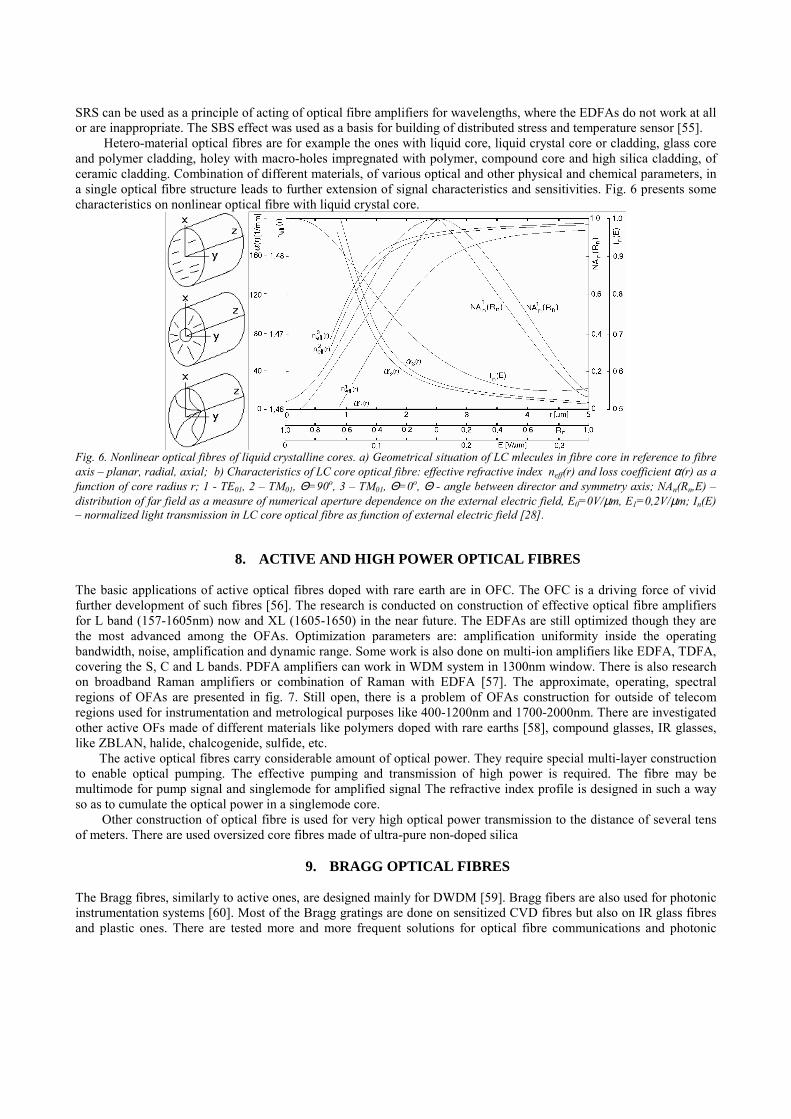
Hetero-material optical fibres are for example the ones with liquid core, liquid crystal core or cladding, glass core and polymer cladding, holey with macro-holes impregnated with polymer, compound core and high silica cladding, of ceramic cladding. Combination of different materials, of various optical and other physical and chemical parameters, in a single optical fibre structure leads to further extension of signal characteristics and sensitivities. Fig. 6 presents some characteristics on nonlinear optical fibre with liquid crystal core.
Fig. 6. Nonlinear optical fibres of liquid crystalline cores. a) Geometrical situation of LC mlecules in fibre core in reference to fibre axis – planar, radial, axial; b) Characteristics of LC core optical fibre: effective refractive index neff(r) and loss coefficient α(r) as a function of core radius r; 1 - TE01, 2 – TM01, Θ=90o, 3 – TM01, Θ=0o, Θ - angle between director and symmetry axis; NAn(Rn,E) – distribution of far field as a measure of numerical aperture dependence on the external electric field, E0=0V/µm, E1=0,2V/µm; In(E) – normalized light transmission in LC core optical fibre as function of external electric field [28].
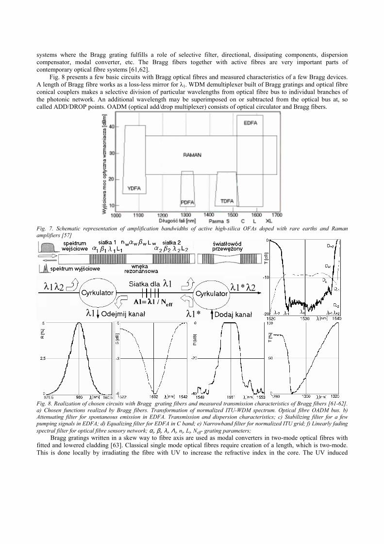
8. ACTIVE AND HIGH POWER OPTICAL FIBRES The basic applications of active optical fibres doped with rare earth are in OFC. The OFC is a driving force of vivid further development of such fibres [56]. The research is conducted on construction of effective optical fibre amplifiers for L band (157-1605nm) now and XL (1605-1650) in the near future. The EDFAs are still optimized though they are the most advanced among the OFAs. Optimization parameters are: amplification uniformity inside the operating bandwidth, noise, amplification and dynamic range. Some work is also done on multi-ion amplifiers like EDFA, TDFA, covering the S, C and L bands. PDFA amplifiers can work in WDM system in 1300nm window. There is also research on broadband Raman amplifiers or combination of Raman with EDFA [57]. The approximate, operating, spectral regions of OFAs are presented in fig. 7. Still open, there is a problem of OFAs construction for outside of telecom regions used for instrumentation and metrological purposes like 400-1200nm and 1700-2000nm. There are investigated other active OFs made of different materials like polymers doped with rare earths [58], compound glasses, IR glasses, like ZBLAN, halide, chalcogenide, sulfide, etc.
The active optical fibres carry considerable amount of optical power. They require special multi-layer construction to enable optical pumping. The effective pumping and transmission of high power is required. The fibre may be multimode for pump signal and singlemode for amplified signal The refractive index profile is designed in such a way so as to cumulate the optical power in a singlemode core.
Other construction of optical fibre is used for very high optical power transmission to the distance of several tens of meters. There are used oversized core fibres made of ultra-pure non-doped silica
9. BRAGG OPTICAL FIBRES The Bragg fibres, similarly to active ones, are designed mainly for DWDM [59]. Bragg fibers are also used for photonic instrumentation systems [60]. Most of the Bragg gratings are done on sensitized CVD fibres but also on IR glass fibres and plastic ones. There are tested more and more frequent solutions for optical fibre communications and photonic
systems where the Bragg grating fulfills a role of selective filter, directional, dissipating components, dispersion compensator, modal converter, etc. The Bragg fibers together with active fibres are very important parts of contemporary optical fibre systems [61,62].
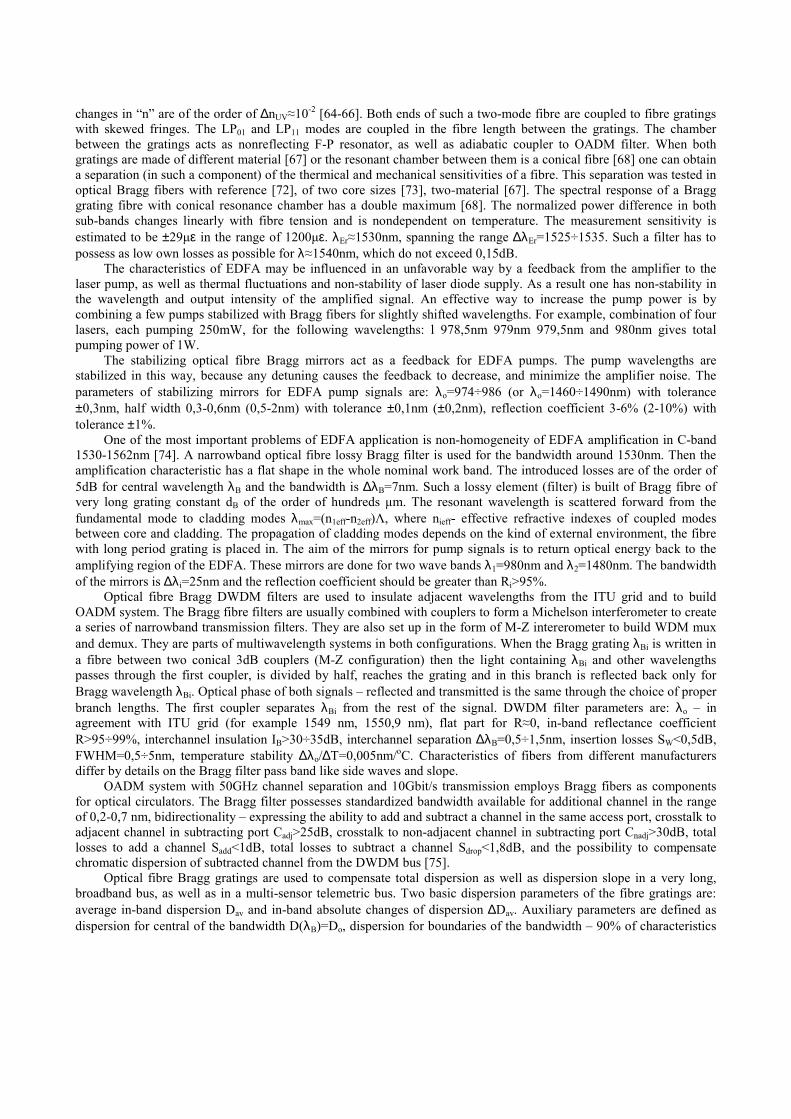
Fig. 8 presents a few basic circuits with Bragg optical fibres and measured characteristics of a few Bragg devices. A length of Bragg fibre works as a loss-less mirror for λ1. WDM demultiplexer built of Bragg gratings and optical fibre conical couplers makes a selective division of particular wavelengths from optical fibre bus to individual branches of the photonic network. An additional wavelength may be superimposed on or subtracted from the optical bus at, so called ADD/DROP points. OADM (optical add/drop multiplexer) consists of optical circulator and Bragg fibers.
Fig. 7. Schematic representation of amplification bandwidths of active high-silica OFAs doped with rare earths and Raman amplifiers [57]
Fig. 8. Realization of chosen circuits with Bragg grating fibers and measured transmission characteristics of Bragg fibers [61-62]. a) Chosen functions realized by Bragg fibers. Transformation of normalized ITU-WDM spectrum. Optical fibre OADM bus. b) Attenuating filter for spontaneous emission in EDFA. Transmission and dispersion characteristics; c) Stabilizing filter for a few pumping signals in EDFA; d) Equalizing filter for EDFA in C band; e) Narrowband filter for normalized ITU grid; f) Linearly fading spectral filter for optical fibre sensory network; αi, βi, λ i, Λi, ni, Li, Neff- grating parameters;
Bragg gratings written in a skew way to fibre axis are used as modal converters in two-mode optical fibres with fitted and lowered cladding [63]. Classical single mode optical fibres require creation of a length, which is two-mode. This is done locally by irradiating the fibre with UV to increase the refractive index in the core. The UV induced
changes in “n” are of the order of ∆nUV≈10-2 [64-66]. Both ends of such a two-mode fibre are coupled to fibre gratings with skewed fringes. The LP01 and LP11 modes are coupled in the fibre length between the gratings. The chamber between the gratings acts as nonreflecting F-P resonator, as well as adiabatic coupler to OADM filter. When both gratings are made of different material [67] or the resonant chamber between them is a conical fibre [68] one can obtain a separation (in such a component) of the thermical and mechanical sensitivities of a fibre. This separation was tested in optical Bragg fibers with reference [72], of two core sizes [73], two-material [67]. The spectral response of a Bragg grating fibre with conical resonance chamber has a double maximum [68]. The normalized power difference in both sub-bands changes linearly with fibre tension and is nondependent on temperature. The measurement sensitivity is estimated to be ±29µε in the range of 1200µε. λEr≈1530nm, spanning the range ∆λEr=1525÷1535. Such a filter has to possess as low own losses as possible for λ≈1540nm, which do not exceed 0,15dB.
The characteristics of EDFA may be influenced in an unfavorable way by a feedback from the amplifier to the laser pump, as well as thermal fluctuations and non-stability of laser diode supply. As a result one has non-stability in the wavelength and output intensity of the amplified signal. An effective way to increase the pump power is by combining a few pumps stabilized with Bragg fibers for slightly shifted wavelengths. For example, combination of four lasers, each pumping 250mW, for the following wavelengths: l 978,5nm 979nm 979,5nm and 980nm gives total pumping power of 1W.
The stabilizing optical fibre Bragg mirrors act as a feedback for EDFA pumps. The pump wavelengths are stabilized in this way, because any detuning causes the feedback to decrease, and minimize the amplifier noise. The parameters of stabilizing mirrors for EDFA pump signals are: λo=974÷986 (or λo=1460÷1490nm) with tolerance ±0,3nm, half width 0,3-0,6nm (0,5-2nm) with tolerance ±0,1nm (±0,2nm), reflection coefficient 3-6% (2-10%) with tolerance ±1%.
One of the most important problems of EDFA application is non-homogeneity of EDFA amplification in C-band 1530-1562nm [74]. A narrowband optical fibre lossy Bragg filter is used for the bandwidth around 1530nm. Then the amplification characteristic has a flat shape in the whole nominal work band. The introduced losses are of the order of 5dB for central wavelength λB and the bandwidth is ∆λB=7nm. Such a lossy element (filter) is built of Bragg fibre of very long grating constant dB of the order of hundreds µm. The resonant wavelength is scattered forward from the fundamental mode to cladding modes λmax=(n1eff-n2eff)Λ, where nieff- effective refractive indexes of coupled modes between core and cladding. The propagation of cladding modes depends on the kind of external environment, the fibre with long period grating is placed in. The aim of the mirrors for pump signals is to return optical energy back to the amplifying region of the EDFA. These mirrors are done for two wave bands λ1=980nm and λ2=1480nm. The bandwidth of the mirrors is ∆λ i=25nm and the reflection coefficient should be greater than Ri>95%.
Optical fibre Bragg DWDM filters are used to insulate adjacent wavelengths from the ITU grid and to build OADM system. The Bragg fibre filters are usually combined with couplers to form a Michelson interferometer to create a series of narrowband transmission filters. They are also set up in the form of M-Z intererometer to build WDM mux and demux. They are parts of multiwavelength systems in both configurations. When the Bragg grating λBi is written in a fibre between two conical 3dB couplers (M-Z configuration) then the light containing λBi and other wavelengths passes through the first coupler, is divided by half, reaches the grating and in this branch is reflected back only for Bragg wavelength λBi. Optical phase of both signals – reflected and transmitted is the same through the choice of proper branch lengths. The first coupler separates λBi from the rest of the signal. DWDM filter parameters are: λo – in agreement with ITU grid (for example 1549 nm, 1550,9 nm), flat part for R≈0, in-band reflectance coefficient R>95÷99%, interchannel insulation IB>30÷35dB, interchannel separation ∆λB=0,5÷1,5nm, insertion losses SW<0,5dB, FWHM=0,5÷5nm, temperature stability ∆λo/∆T=0,005nm/oC. Characteristics of fibers from different manufacturers differ by details on the Bragg filter pass band like side waves and slope.
OADM system with 50GHz channel separation and 10Gbit/s transmission employs Bragg fibers as components for optical circulators. The Bragg filter possesses standardized bandwidth available for additional channel in the range of 0,2-0,7 nm, bidirectionality – expressing the ability to add and subtract a channel in the same access port, crosstalk to adjacent channel in subtracting port Cadj>25dB, crosstalk to non-adjacent channel in subtracting port Cnadj>30dB, total losses to add a channel Sadd<1dB, total losses to subtract a channel Sdrop<1,8dB, and the possibility to compensate chromatic dispersion of subtracted channel from the DWDM bus [75].
Optical fibre Bragg gratings are used to compensate total dispersion as well as dispersion slope in a very long, broadband bus, as well as in a multi-sensor telemetric bus. Two basic dispersion parameters of the fibre gratings are: average in-band dispersion Dav and in-band absolute changes of dispersion ∆Dav. Auxiliary parameters are defined as dispersion for central of the bandwidth D(λB)=Do, dispersion for boundaries of the bandwidth – 90% of characteristics

decrease D±1(λ±1), half characteristic height dispersion D±2(λ±2). These parameters are marked on a normalized dispersion characteristic of a Bragg fibre and presented in fig. 8. Homogeneous gratings have considerable dispersion at the edges of transparency band. Chirped gratings have considerable non-zero dispersion inside the entire band [76].
Bragg gratings (also ones of long period) are used for numerable solutions of optical fibre sensors. The most interesting applications were photonic sensors distinguishing simultaneously thermal and mechanical reactions as well as in systems with linear conversion and/or discrimination of wavelength. The fibres for these sensors require usually a thick silicone or polyimide cladding (jacket). The basic required parameter for mechanical and thermical fibre sensor is a narrowband filter characteristic. The values, which are obtained here are ∆λB≈0,15÷0,2nm at R>80% in wave bands 1300nm and 1500nm. On the other hand linear discriminators need high linearity of the discriminating slope (of a few %) and its extent (15-30 nm).
10. CONICAL OPTICAL FIBRES Optical fibres with functionally changing of external dimensions, for example conical ones, are equivalent to the ones with NA aperture and RIP changing along fibre length [77]. A typical fibre narrowing, acting as a coupler or evanescent field sensor, is for particular length, a multimode clad-less optical rod waveguide. Optical fibres from multi-component glasses allow building good 3dB couplers, for chosen bandwidth and complex hetero-profile cones of non-symmetrical coupling characteristics. Biconical fibre components are used as devices for more complex subsystems, together with Bragg fibre gratings [78]. A stair-case model of doubly conical optical fibre for analysis is presented in fig.9.
Rys.9. Światłowód przewężony, jego model schodkowy do analizy i wybrane charakterystyki obliczone i zmierzone. Dane włókien I i II: IP -długość rejonu o Vc<1 lwm=15mm, długość talii lt=2,5mm, standardowa średnica zewnętrzna włókna 125µm, światłowód I - średnica rdzenia 2r=4,5µm, n1=1,464, n2=1,460, λ1=633nm, λ2=1,3µm, światłowód II – średnica rdzenia 9,5µm; Charakterystyki: 1 i 2-T(LP) –obliczona i zmierzona transmisja T w funkcji długości przewężenia LP dla światłowodu I, 3 i 4 –T(Θ) – Obliczone charakterystyki transmisji w funkcji kąta wygięcia przewężenia dla światłowodu I i długości fali λ2 i λ1; 5- r(z) zmierzony profil geometryczny przewężenia światłowodu I; 6 – C(Lc) - zmierzony współczynnik sprzężenia w funkcji długości wydłużenia w czasie wyciągania przewężenia dla dwóch światłowodów II;
11. PLASTIC OPTICAL FIBRES Multimode gradient index, plastic, optical fibres [79], similar to multimode glass fibres in signal properties sense, differ from them by elasticity, way of joining and building of local transmission systems. These differences are quite attractive and thus the further intense research is going on the development of these fibres. Now the most important problems are in the multimode area to stabilize the available technologies of cheap, low-loss fibres of optimal gradient index [80]. In the area of image transmission the basic work are to increase the contrast and resolution and decrease price of disposable imageguides for medical purposes [81]. We investigated the differential characteristics of imageguides: glass versus plastic [82]
Plastic optical fibres are subject of investigations because of their low costs and other favourable features they possess in such applications as: imageguides, sensors, nonlinear components, and transmission systems for short lengths. Optical fibres (and also lens matrices, GRIN components) are made of PMMA, fluoro-polymers FP and

polystyrene PS. Low-loss transmission plastic optical fibres and plastic optical cables are one of the hopes for low-loss access with a fibre to the home. (the last mile program). Other transmission applications are at home area for multimedia distribution (Toslink, etc.). The bandwidth of plastic multimode optical fibres is 1-5GHz/100m for gradient index and 200MHz/100m for step index for core diameter of 100 µm. Optical fibres of big diameters do not require precise joints. The dimensions are standardized to 300µm, 500µm, 750µm, 1mm. Plastic connectors are possible. Preparation of end faces is much easier. Cutting requires only little experience. There is no need for expensive connector kits. Just a drop of immersion fluid is sufficient. Plastic optical fibres work in the visible are in photonic systems. They are much more elastic than glass ones. Nominal temperatures for work are from –40 to +125oC. They have small chemical resistance. Typical outside diameter is 1mm. They are resistant to vibrations and mechanical wear. They are used with LEDs for the band 650-665nm (GaAsP 665nm - red, AlGaAs 662nm red), or 500-600nm (GaP 565nm -green, GaP 583 –yellow). The second band is less popular because the power is lower and diodes are slower. The bands used with pPS fibres are 580-625nm and 675nm. Local absorption minimum is for 650nm. PS gets yellow under the UV radiation. PS is less hygroscopic than PMMA.
Fig. 10 presents measured spectral loss characteristics and dispersion of investigated by us plastic optical fibres.
Fig. 10. Characteristics of plastic optical fibres. a) Measured spectral loss for high quality step-index plastic optical fibres made of PMMA/FP and PS/PMMA (own measurements). 2a=100µm, d=750µm, NA≈0,5; b) Calculated and measured RIPs of gradient index plastic optical fibres (Asahi GC, BOF MA) and their dispersion characteristics. Profiles 1-4 calculated for n=1,49÷1,5, 1-αpe=4, 2-αpe=3, 3- αp=2, 4-αpe=2, Profiles 5-7 for n=1,49÷1,59; 5-αp=3, 6-measured profile, 7-αpe=3,6;
12. SENSITIZED OPTICAL FIBRES Technologically sensitized optical fibres (SOF) or desensitized ones [83-85] are a large group of fibres designed for particular application. For example, fibres of sensitive cladding to electrical fields are designed for photonic electrical values measurements. SOFs can be divided to: sensitive cladding fibres, differential characteristics between core and cladding fibres, sensitive material fibres, and ones of complex internal structure. Fig. 11 presents examples of chosen, measured or calculated characteristics of sensitized optical fibres made in Białystok Fibre Optical Laboratories. Some of these fibres are representatives of larger abovementioned groups.
Additional stages of technological process may lead to sensitizing of optical fibre to certain reactions. Just opposite to telecom fibres where one expects small sensitivities to external fields like temperature changes and microbending. Microbending losses αm are function of ∆n(T). Temperature sensitivity is enhanced in PCS optical fibres, where polymer refractive index changes much faster with temperature. Fig. 11 presents a few chosen pairs of glasses for core-cladding setup. Functions n(T) cross each other in some pairs, giving the condition of NA=0 and then the effect of reversed waveguide. Similarly the dispersion curves of core-cladding material may cross each other.
13. MULTICORE OPTICAL FIBRES MOF are, similarly to elliptical core optical fibres, one of basic kinds of TOF. MOF require comparatively complex manufacturing methods. MOF are now not designed for long distance transmission. They were even removed by two-mode optical fibres [87-88] in some sensing and transmission applications. These two-mode optical fibres were

classical ones working in two-modal condition (HE11 and EH01 or LP11 and LP01). We mastered technology of manufacturing MOF in several basic kinds [89-90] and techniques to manipulate with them [91-92]. Some functional photonic components were manufactured of these fibres [93-94]. Coupled mode propagation was obtained in a singlemode MOF of closely located cores [95-96].
Fig. 11. Characteristics of SOFs by the choice of fibre material (core-cladding pair). a) Measured effect of zeroing numerical aperture of optical fibre in glass pairs of different thermal refraction dispersion. Glasses: BaSF12, BaFN10, SK52, SF7, BaK1, TiF1. b) Measured curves for numerical aperture dispersion for TOFs. c) Measured material dispersion curves for chosen compound glasses for fibres, d) Dispersion of group index for multicomponent fibre glasses. The condition of zeroing material dispersion dng/dλ=0 is not fulfilled for some multicomponent glasses for fibres in the transparency region.
It is predicted that MOF may introduce to photonic system a few new transmission and signal processing possibilities. These possibilities stem from modal properties of certain groups of MOF. The most important three of them are: intercore wave interference, signal multiplexing between cores and multichannel transmission. These features may be used for quite different purposes. Multi-channel property of MOF, for appropriate singlemode core separation, may be used for lowering of BER, transmission stabilization or increasing of reliability. The intercore wave interference gives the possibility to realize internal, single optical fibre interferometer. Two or more coupled cores in a MOF work simultaneously as reference and measuring channels. Internal interference is combined with natural properties of singlemode MOF of appropriate geometrical dimensions and refractive structure. More cores than two, depending on their mutual localization, may be used for building interferometers of quite complex structure, for example quadruple and quadrature detection. The structure may be used to increase the system noise performance (decrease OSNR, BER). The system allows for: doubling of reference channel, introduction of confirmation channel for both directions of channel propagation, compensation for constant line delay, introduction of constant difference in optical pathways between channels (controlling of optical phase), realization of optical loop delay line of changed delay in steps.
Fig. 12. Calculated from the eigenequation fundamental modal characteristics of single-mode, twin-core ptical fibres; a) Dispersion curves β(V) for modes SA1, AS1, HE11 and modes SS1, AA1, ∆=1,5%; ∆ –relative differential refraction of the fibre; S.A.- Symmtrical-Antisymmetrical modes; b) Birefringence function ∆βAS(V) for different values of dN=d/a parameter; a-core radius, d-core separation, dN-normalized separation between cores; ∆βAS-differential propagation constant between cores; c) Function ∆βAS (∆) for different values of normalized frequency V=1÷5; V-normalized frequency;
Comparizon of a single-fibre. MOF interferometry with classical solutions of two fibres MZ interferometry reveals a number of profound differences between them. These differences may be profitable in some applications, while unfavourable or even disqualifying in some others. The interferometer with single fibers has separate channels in both branches, which may be configured according to the need of application. The reference channel may be separately tuned. On the other hand, the sensitivity and selectivity of a MOF interferometer is technologically tuned during the MOF manufacturing process. The factors influencing the parameters of MOF interferometer are: core separation, numerical apertures of individual core, core diameters, individual RIPs, absolute value of refraction in individual cores

and in cladding, structure of fibre between the adjacent cores. The change of sensitivity in an interferometer requires change of optical path-length in the measuring arm. Effective change of sensitivity of single fibre interferometer requires changing the fibre for a different one. Single fibre interferometer possesses, according to our experience, slightly smaller sensitivity to the measurands and environmental reactions than the classical one. A double arm interferometer may be realized too, using MOFs. This also changes a lot giving new possibilities to configure the interferometer and to tune its properties. The reference and measuring arms may carry signals in both directions. Multiplexing of the signal between the cores in MOF is associated with strong coupling between these cores existing or forced at some fibre length. Normally in such a case the cores should remain uncoupled. Forced coupling may be internal or external to the MOF, active or passive. This internal feature of MOF may be a base for the construction of functional components like: 1) core multiplexed transmission channels CDM (Core Division Multiplexing) per analogiam to WDM, TDM, PCM, FDM. These components may be subassemblies for all-fibre switching matrices; 2) Functional photonic components – couplers, photonic keys, insulators, filters, nonreciprocal elements, etc., 3) optical fibre MOF sensors, using CDM, multichannel transmission, internal interference for the detection and conversion of given values. In particular, switching of the signal and multiplexing (passive and active), also done outside of the fibre, may be used to construct an artificial skin containing such sensors like tactile, grip, slip, touch and touch distribution. Switching of the signal between cores is done in MOF at discrete points as well as in distributed way. This leads to possibility to detect distributed signals and reading the result from the reflectometric trace. The third feature of MOF, multichannel transmission ability, is a fundament for controlled redundancy. The redundancy may be exchanged for: 1) stabilization and linearization of optical transmitters and receivers. The signal is send back proportional to the level of optical power in the receiver and is used for tuning the power of transmitter. This method serves to exchange the redundancy for system quality – minimization of required energy, OSNR optimization, system reliability increase, improvement of signal quality at the receiver; 2) Building of network loop elements (resonators) with traveling wave, to serve for all-photonic node, as a photonic cache memory, multi-channel detection with delay; 3) Realization of transmission channels with multi-parameter flow for cryptographical purposes, multilevel coding, new methods of digital signal modulation and coding; 4) Realization of photonic buses and nodes of transparent optical network; MOFs may be used as transmission lines and functional components in the future. Signal processing in a MOF has its base in intercore differential characteristics. These characteristics are subject to MOF design. They have inbuilt character in a hetero-core MOF or induced (either residual) in a homo-core MOF. The differential characteristics stem from many MOF parameters, and complexity of the manufacturing process. Such components were built using this kind of differential characteristics: bend filters, couplers, conical components, modal converters, and selective attenuators. Differential intercore losses are used for dynamic power level regulation along the fibre. The signal subject to attenuation is switched to lossy core for a while and then returned back to the transmissive core with proper power level. The same method is applied for active core and signal amplification. Practical application of these, and a lot of more (modal conversion, signal coding, clock change, code regrouping, separation of chosen pulse sequence, all-photonic multiplexing and demultiplexing) solutions depends on financing of MOF investigations. As till now the MOFs remain just laboratory curiosity and still are not attractive competitors with alternative optical fibre technologies. Figures 12 and 13 present chosen characteristics of tow-core and quadruple-core MOFs.
Fig. 13. Modal characteristics of Quadruple-core MOF. Fibre has square distribution of equal cores. a) Calculated normalized propagation constants for SA fundamental modes of the MOF with square distribution of identical cores as function of normalized frequency (fundamental dispersion characteristics); βN=(β2/ko
2-ε5)(ε1-ε5); εi(i=1,2,3,4) core refraction; εi(i=5) cladding refraction; homo-core conditions- n1=n2=n3=n4=nr=(ε1)1/2>n5=np, a1=a2=a3=a4=a; Fibre data: core diameter 2a=2,5µm, intercore separation d=0,5µm, NA=0,05≈0, core refraction n1=nr=1,6, step-index RIP, curve 1 – four degenerated modes fot ideally isotropic MOF SA+x,

SA-x, AS+y, AS-y; curve 2 – three-index modal family SAA+x, ASA-y, etc.; curve 3 – single-index family: S±x, S±x*, S±y, S±y*, A±x, A±x*, A±y, A±y*, where A*=A± with changed succession of +- signs instead of ± should bem ; curve 4 – fundamental modes SA±y, SA±y*, AS±x, AS±x*; curve 5 – reference to fundamental mode HE11 for classical fibre of analogical parameters, curve AS2
+y – cut-off and dispersion curve for modes of the second order in quadruple core fibre; b) Schematical representation, numerically calculated, field distributions of fundamental SA modes in QC-MOF; Basic symmetrica mode (S), Basic symmetric-antisymmetric mode (SA), Basic antisymmetric mode (A), Basic symmetric mods SA (SAS), Coupled antisymmetric mode SA (ASA=SAS+ASS).
14. INFRARED OPTICAL FIBRES IROF technology operates in the spectral range 2÷30µm. The subject of interest to IROF are materials, glasses, polycrystals, crystals, polymers transparent in this region and susceptible to making out of them fully structured optical fibres [97]. Numerable IR glasses have close glass transition Tg and crystallization temperatures Tk, and exhibit strong crystallization tendency during the high temperature processing. The following conditions may be defined for IROF glasses: 1) Stability to devitrification processes in sufficiently brad range of temperatures; 2) Sufficiently low viscosity to pull a fibre; 3) Sufficiently high Tg, higher than room temperature; 4) As big difference between Tk and Tg; 5) Susceptibility to ultrapurification; 6) Mechanical and chemical stability, especially with respect to water; 7) Nontoxic; 8) Susceptibility to be covered with other glassy material to form structured core-cladding fibre; 9) Broad range of optical transparency and low-losses; 10) Susceptibility to precise doping effectively changing the refractive properties of material. As hypothetical advantages of IROF are mentioned: low-losses of fibres, increase of singlemode fibre dimensions, lower sensitivities of fibre to external reactions.
Four groups of potential applications are mentioned for IROF technology: power transmission, IR fibre microoptics, radiometry, IR sensors and hypothetically communications. A few hundred W from C02 laser were transmitted along IROF. Other bands (3÷6µm, and above 11µm) have their own technical specificity connected with available power sources and low-loss materials. IROF microooptics is: slabs, cones, lenses, GRIN, prisms, imageguides, coders, image converters. Radiometric applications are combined with coherent matrixes of IROF. Potential applications have not been realized. They are connected with ultra-low-losses of some materials in the IR region.
15. COMPLEXOPTICAL FIBRES
Complex optical fibres [98-100] are filaments of internal structure, which is difficult, or impossible to be done with classical MCVD. Many of such fibres have not yet been described. They are manufactured using hybrid methods or combination of a few simpler processes. The literature treats such fibres in the quest for new optical and signal transmission properties [101-105].
16. CONCLUSIONS
Technology and technique of TOF are, from same time. A separate branch of optical fibre photonics. TOFs are used for building photonic components to process transmitted optical wave. Such components find some applications in photonic transmission, telemetric and information systems. The characteristics of TOFs can be tailored in comparatively broad range and realized practically.
17. ACKNOWLEDGEMENTS
The author would like to thank prof J.Dorosz of Białystok University of Technology for close and long lasting cooperation in the research on TOF.
18. REFERENCES [1] WDM Solutions, Laser Focus World, PennWell [2] R.Romaniuk, J.Kociszewski, Technika światłowodowa i jej zastosowania nietelekomunikacyjne, III Kraj. Symp. Nauk Radiowych URSI, Prace Naukowe PWr., Tom 47, Wrocław 1981

[3] ] J.Dorosz, R.Romaniuk, Optical fibres with shaped cores and their applications, VI Fiber Optics and Communications Conf., Los Angeles, 1982, str. 89-90 [4] G.Bechtel, Optical IC market, WDM Solutions, July 2001 [5] T.G.Giallorenzi et al., Optical fiber sensor technology, IEEE JQE, Vol 18, no 4, 1982, pp 626-665 [6] J.Wójcik, Technologia światłowodów specjalnych, Elektronika, nr 3, 2001 [7] R.Romaniuk, J.Dorosz, Wielotyglowa-strefowa technologia wytwarzania szklanych światłowodów włóknistych, Szkło i Ceramika, nr 3, 1983, str.93-99 [8] B.Culshaw, J.Dakin (edit.), Optical fiber sensors, Vol.1-3, Artec House, Boston, 1989-1995 [9] J.Dorosz, Światłowody tyglowe, Elektronika, nr 5, 1982 [10] J.Dorosz, R.Romaniuk, Technologia światłowodów trzytyglowych i czterotyglowych, III Kraj. Symp. Światłowody i Ich zastosowania, Jabłonna 1983, Tom I, str. 29-41 [11] R.B. Dyott, Elliptical fiber waveguides, Artech House, London 1995 [12] C.G.Someda, A.Galtarossa, Theory of linearly birefringent fibers, Optics Letters, Vol 24, 23, Dec., 1999, pp. 1690-1692 [13] R.Romaniuk, J.Dorosz, Multicore single-mode soft-glass optical fibers, Optica Applicata, nr 1-2, 1999, pp.15-49 [14] T. A. Birks, et. al., Endlessly single-mode photonic crystal fiber, Optics Letters, vol. 22, pp. 961-963, 1997 [15] R.Romaniuk, R.Stępień, Glass-ceramic fiber optic sensors, Proc. SPIE, Vol, 1368, 1990, str. 73-84 [16] A.Diez, M.V.Miguel, J.L.Cruz, Hybrid modes in circular metal-coated fibers, JOSA A, Vol. 16, No. 12, 1999, pp.2978-2982 [17] G.P.Agrawal, Nonlinear fiber optics, Academic Press, Boston, 1995 [18] K.Jędrzejewski, R.Stępień, D.Denis, Z.Mierczyk, M.Kwaśny, Szkła i światłowody aktywne, Elektronika, nr 2, 2001 [19] H.F.Taylor, Bending effects in optical fibers, IEEE JLT, Vol. 2, 1984, pp.617-628 [20] W.V.Sorin, et.al., Selective evanescent modal filter for two-mode optical fibers, Optics Letters, Vol. 11, 1986, pp.581-583 [21] K.Jędrzejewski, A.Kosiński, Wide-band tapered directional coupler, Proc. SPIE, Vol. 3189, 1997, pp.130-132 [22] R.Romaniuk, J.Dorosz, Właściwości światłowodów tyglowych ze szkieł domieszkowanych cerem, Elektronika, nr 2, 1984 [23] S.S.Johal, S.W.James, R.P.Tatam, G.J.Ashwell, Second-harmonic generation in Langmuir-Blodgett waveguide overlays on single-mode optical fiber, Optics Letters, Vol 24, 17, Sept, 1999, pp.1194-1196 [24] Proceedings of Int. Conf. Plastic Optical Fibers and Applications, 1997, Kauai, HI [25] L.J.Dobnalds, W.G.French, W.C.Mitchell, R.M.Swineheart, T.Wei, Electric field sensitive optical fiber using piezoelectric polymer coating, Electronics Letters, Vol. 18, 1982, pp. 327-328 [26] A.Dybko, W.Wróblewski, J.Maciejewski, Z.Brzózka, R.Romaniuk, Własności intefejsu chemooptycznego – struktura warstwy czujnikowej, IV Konf. Czujniki Optoelektroniczne i Elektroniczne, Szczyrk, 1996, str.279-282 [27] A.H.Hartog, A distributed temperature sensor based on liquid-core optical fibres, JLT, Vol. 1, 1983, pp.498-503 [28] T.Woliński et al., Propagacja światła w światłowodach ciekłokrystalicznych, V Konf. Światłowody i ich Zastosowanie, Białowieża, 22-24.01.1998, str.287-293 [29] S.R.Norman, D.N.Payne, M.J.Adams, A.M.Smith, Fabrication of single mode fibres exhibiting extremely low polarization birefringence, Electronics Letters, Vol. 15. 1979, pp. 309-311 [30] T.A.Eftimov, W.J.Bock, Analysis of the polarization behavior of hybrid modes in highly birefringent fibers, J. Lightwave Technology, Vol. 16, No 6, 1998, pp.998-1005 [31] M.P.Varnham, D.N.Payne, D.N.Birch, E.J.Tarbox, Single polarization operation of highly birefringent bow-tie optical fibres, Electronics Letters, Vol. 19, 1983, pp. 246-247 [32] R.D.Birch, Fabrication and characterization of circularly-birefringent helical fibres, Electronics Letters, Vol.23, 1987, pp.50-52 [33] K.O.Hill, Y.Fujii, D.C.Johnson, B.S.Kawasaki, Photosensitivity in optical fiber waveguides, Application to reflection filter fabrication, Applied Physics Letters, Vol. 32, 1978, pp.647-649 [34] S.Inao, T.Sato, S.Sentsui, K Turoha, Y.Nishimura, Multicore optical fiber, OFC’79, p.46-47 [35] J.Wójcik, et al., Prototype side-hole optical fiber, Proc. SPIE, vol. 3731, pp.88-92 [36] J.K.Ranka, R.S.Windeler, A.J.Stentz, Optical properties of high-delta air–silica microstructure optical fibers, Optics Letters, Volume 25, 11, June, 2000, pp. 796-798 [37] K.Jensen, R.Ulrich, Drawing glass fibers with complex cross section, IEEE JLT, Vol. 9, No 1, 1991, pp.2-6 [38] R.Romaniuk, et.al., Technological sensitizing of mosaic optical fibers for sensory and microoptics applications, Proc. SPIE, Vol. 1128, str. 25-37, 1989 [39] C.A.Millar, B.J.Ainslie, M.C.Brierley, S.P.Craig, Fabrication and characterisation of D-fibers with a range of accurately controlled core/flat distances, Electronics Letters, Vol 22, 1986, pp.322-324 [40] R.Romaniuk, Tensile strength of tailored optical fibers, Opto Electronics Review, nr 2, 2000, pp. 103-118 [41] T.Izawa, S.Sudo, Optical fibers – materials and fabrication, KTK Sci. Publ., Tokyo, 1996 [42] S.C.Rashleigh, Origins of polarization in single mode fibres, J. Lightwave Technology, Vol. 1, 1983, pp. 312-331 [43] A.J.Barlow, D.N.Payne, M.R.Hadley, R.J.Mansfield, Production of single mode fibres with negligible intrinsic birefringence and polarization mode dispersion, Electronics Letters, Vol.17, 1981, pp.725-726 [44] R.S.Romaniuk, K.Jędrzejewski, P.Pańta, Properties of home-made MCVD, PCS and DC/TC optical fibres, Proc. SPIE, 404, 1983, str.96-101 [45] A.M.Smith, Polarisation and magneto-optical properties of single-mode optical fibres, Appl. Optics, Vol. 17, 1978, pp. 52-56

[46] A.H.Rose, S.M.Etzel, K.B.Rochford, Optical fiber current sensor in high electric field environments, IEEE JLT, Vol. 17, 1999, No 6, pp. 1042-1048 [47] J.Dorosz, R.Romaniuk, Developments of multicrucible technology of tailored optical fibers, Proc.SPIE, Vol. 3731, str. 32-58 [48] R.Romaniuk, Manufacturing and characterization of ring-index optical fibers, Opt. Applic., Vol. 31, No. 2, 2001, pp. 425-444 [49] V.Ramaswamy, W.G.French, R.D.Standley, Polarization characteristics of non-circular single mode fibers, Applied Optics, Vol 17, 1978, pp.3014-3017 [50] R.Romaniuk, J.Dorosz, Opracowanie technologii światłowodów o eliptycznym kształcie rdzenia, Inżynieria Fotoniczna, Politechnika Warszawska, 2000 [51] T.Okoshi, K.Oyamoda, Side tunnel fibre: an approach to polarization maintaining optical waveguiding scheme, Electronics Letters, Vol.18, 1982, pp. 824-826 [52] ] J. C. Knight, et. al., Photonic band gap guidance in optical fibers," Science, vol. 282, p. 1476, 1998 [53] R.G.Smith, Optical power handling capacity of low loss optical fibers as determined by stimulated Raman and Brillouin scattering, Applied Optics, vol.11, pp.2489-2494, 1972 [54] Międzynarodowe standardy dotyczące światłowodów ISO, DIN, ANSI, IEC, IEEE, ITU-T [55] H.H.Kee, G.P.Lees, T.P.Newson, All-fiber system for simultaneous interrogation of distributed strain and temperature sensing by spontaneous Brillouin scattering, Optics Letters, Volume 25, 10, May 2000, pp. 695-697 [56] M.Digonnet (edit.), Selected papers on rare-earth-doped fiber laser sources and amplifiers, SPIE , Vol. MS-37, 1992 [57] www.ipgphotonics.com [58] A.Dodabalapur, et.al., Organic solid-state lasers: Past and future, Science, Vol. 277, 1997, p.1787 [59] K.O.Hill, G.Meltz, Fiber Bragg grating technology: Fundamentals and overview, IEEE JLT, Vol. 15, 1997, pp.1263-1276 [60] A.D.Kersey, M.A.Davis, H.J.Patrick, M.LeBlanc, K.P.Koo, C.G.Askin, M.A.Putnam, E.J.Friebele, Fiber grating sensor, IEEE J. Lightwave Technology, Vo. 15, 1997, pp. 1442-1463 [61] Brag Photonics, www.braggphotonics.com [62] Innovative Fibers, www.infibers.com [63] C.D.Poole, et.al., Helical grating two-mode fiber spatial-mode coupler, IEEE JLT, Vol. 9, 1991, pp.598-603 [64] D.Johlen, H.Renner, A.Ewald, E.Brinkmeyer, Fiber Bragg grating Fabry-Perot interferometer for a precise measurement of the UV induced index change, ECOC, Madrid, 1998, pp.393-394 [65] D.Johlen, F.Knappe, H.Renner, E.Brinkmeyer, UV-induced absorption, scattering and transition losses in UV side written fibers, OFC, Washington DC, 1999, pp.50-52 [66] D.Johlen, H.Renner, P.Klose, E.Brinkmeyer, UV-writing of two-mode sections into single mode finbers for hosting mode-converting Bragg gratings, IEEE PTL, Vol. 11, No 8, 1999, pp. 1015-1017 [67] P.M.Cavaleiro, F.M.Araujo, L.A.Ferreira, J.L.Santos, F.Farahi, Simultaneous measurement of strain and temperature using Bragg gratings written in germanosilicate and boron-doped germanosilicate fibers, IEEE PTL, Vol. 11, 1999, pp. 1635-1637 [68] W.Du, X.Tao, H.Tam, Temperature independent strain measurement with a fiber grating tapered cavity sensor, IEEE PTL, Vol. 11, No, 5, May 1999, pp.596-598 [69] A.D.Kersey, T.A.Berkoff, W.W.Morey, Fiber optic Bragg grating strain sensor with drift compensated high resolution interferometric wavelength shift detection, Opt. Lett., Vol. 18, 1993, pp. 72-74 [70] M.Xu, J.L.Archambault, L.Reekie, J.P.Dakin, Discrimination between strain and temperature measurement using dual wavelength fiber grating sensor, El. Lett., Vol. 30, 1994, pp.1085-1087 [71] H.J.Patrick, G.M/Williams, A.D.Kersey, J.R.Pedrazzani, A.M.Vengsarkar, Hybrid fiber Bragg grating/long periofd fiber grating sensor for stain/temperature discrimination, IEEE PTL, Vol. 8, 1996, pp. 1223-1225 [72] S.E.Kanellopoulos, V.A.Handrek, A.J.Rogers, Simultaneous strain and temperature sensing with photogenerated in-fiber gratings, Opt. Lett., Vol. 20, 1995, pp. 333-335 [73] W.Du, et. al., Fiber Bragg grating cavity sensor for simultaneous strain and temperature, IEEE PTL, Vol. 11, 1999, pp.105-107 [74] R.Romaniuk, Ewolucja Telekomunikacji Światłowodowej w Kierunku Pasma L, Elektronika, Vol. 42, Nr. 5, 2001, str. 6-11 [75] Międzynarodowe standardy dotyczące światłowodów: ISO, ANSI, IEC, IEEE, ITU [76] X. Chen, Z.Ma, W.Li, X.Yin, Z.Wu, Superchirped moiré grating based on an acousto-optic superlattice with a chirped fiber Bragg grating, Opt. Lett., Volume 24, 22, 1999, pp. 1558-1560 [77] B.S.Kawasaki, K.O.Holl, R.G.Lamont, Biconical-taper single mode fiber coupler, Opt. Lett., Vol. 6, No 7, 1981, pp. 327-328 [78] A.Diez, M.V.Andres, E.Silvestre, P.Andres, Tapered optical fiber devices, Proc. SPIE, Vol. 3572, 1999, pp. 147-150 [79] C.Emslie, Review: Polymer optical fibers, J. Material Science, Vol. 23, 1988, pp. 2281-2293 [80] T.Ishigure, A.Horibe, E.Nihei, Y.Koike, High Bandwidth high numerical aperture graded-index polymer optical fiber, IEEE JLT, Vol. 13, 1995, pp.1686-1691 [81] F.Suzuki, Novel plastic image transmitting fiber, Proc. SPIE, Vol. 1592, 1991, pp.150-157 [82] L.Kociszewski, J.Buźniak, D.Pysz, R.Romaniuk, Wpływ struktury na jakość przenoszonego obrazu w obrazowodach światłowodowych, Symp. Technika Przetwarzania Obrazu, IMiO, Politechnika Warszawska, Warszawa 22-23.09.1989, str.67-80 [83] R.Romaniuk, L.Kociszewski, R.Stępień, J.Buźniak, Technological sensitizing of mosaic optical fibers for sensory and microoptics applications, Proc. SPIE, Vol. 1128, str. 25-37, 1989 [84] R.Romaniuk, Special fibres for application environments, Proc. SPIE, Vol. 1174, str. 332-357, 1989
[85] R.Stępień, L.Kociszewski, J.Buźniak, R.S.Romaniuk, Synthesis of sensitizing glasses in very small volumes and strictly controlled atmospheres for fiber and integrated optic sensors, Proc. SPIE, Vol, 1177, str. 438-448, 1989 [86] J.Dorosz, Tyglowe metody wytwarzania światłowodów wielordzeniowych, Rozprawy Naukowe Politechniki Białostockiej, Tom 29, Białystok 1995 [87] K.A.Murphy, M.S.Miller, A.M.Vengsarkar, R.O.Claus, Two-mode optical fiber sensor implementation, IEEE JLT, Vol. 8, 1990, pp.1688-1691 [88] C.D.Poole, J.M.Wiesenfeld, A.R.McCormick, K.T.Nelson, Broadband dispersion compensation by using the higher order spatial mode in a two-mode fiber, Opt. Lett., Vol. 17, 1992, pp.985-887 [89] R.S.Romaniuk, Multicore optical fibres for sensors, Proc. SPIE, Vol. 566, 1985, str. 276-283 [90] J.Dorosz, R.Romaniuk, Manufacturing and measurements of triple-core, double-core and twin-core single-mode soft-glass optical fibers, Proc. SPIE, Vol. 3731, str. 59-71, 1998 [91] R.S.Romaniuk, J.Dorosz, A family of multicore optical fibre based sensors and instrumentation systems, 2nd International Conference on Optical Fiber Sensors, Stuttgart, „OFS’84”, 1984, pp. 275-278 [92] R.S.Romaniuk, J.Dorosz, Coupled/noncoupled wave transmission in long length of multicore optical fibres, Xth European Conference on Optical Communication, „ECOC’84”, Stuttgart, 1984, pp. 202-203 [93] R.S.Romaniuk, J.Dorosz, Multicore optical fiber components, Proc. SPIE, Vol. 722, 1986, pp.117-124 [94] R.S.Romaniuk, J.Dorosz, Multicore microoptics, Proc.SPIE, Vol. 1014, 1988, str.120-129 [95] R.S.Romaniuk, Single-mode quadruple-core optical fibres, Proc.SPIE, Vol. 1085, pp. 214-238, 1989 [96] R.Romaniuk, J.Dorosz, Multicore single-mode soft-glass optical fibers, Optica Applicata, Vol. 29, No. 1-2, 1999, pp. 15-49 [97] R.Romaniuk, J.Dorosz, Przegląd materiałów dla techniki światłowodowej w średniej podczerwieni, Szkło i Ceramika, Vol. 34, Nr 2, 1983, str. 49-55 [98] R.Romaniuk, L.Kociszewski, R.Stępień, J.Buźniak, Mosaic optical fibers, Proc.SPIE, Vol. 1085, str. 239-272, 1989 [99] J.Dorosz, R.Romaniuk, Exotic optical fibres, Proc. SPIE, 1085, pp. 273-276, 1989 [100] J.Dorosz, R.Romaniuk, Multicrucible technology of tailored optical fibers, Opt. Applic., Vol. 28, No. 4, 1998, pp. 293-322 [101] P.S.Westbrook, B.J.Eggleton, R.S.Windeler, A.Hale, T.A.Strasser, G.L.Burdge, Cladding-mode resonances in hybrid polymer-silica microstructured optical fiber gratings, IEEE PTL, Vol. 12, No 5, 2000, pp. 495-497 [102] L.Eyges, P.Gianino, P.Wintersteiner, Modes of dielectric waveguides of arbitrary cross section, JOSA, Vol 69, 1979, p.1226 [103] K.Jensen, R.Ulrich, Drawing glass fibers with complex cross section, IEEE JLT, Vol. 9, No 1, 1991, pp.2-6 [104] J.Dorosz, R.Romaniuk, Światłowody Kształtowane, Oddział Badawczo-Produkcyjny Światłowodów, HS Biaglass, Noty Aplikacyjne i Katalog Urządzeń Światłowodowych, (we współpracy z Programem Priorytetowym Politechniki Warszawskiej Inżynieria Fotoniczna), Białystok–Warszawa, Maj 1999 [105] S.B.Poole, D.N.Payne, Special optical fibres, Proc. SPIE, Vol. 734, 1987, pp.92-103
From left: prof Jan Dorosz, dr Ryszard Romaniuk and dr Feliks Szczot in the Białowieski Hotel lobby just before the opening ceremony of the VIIIth Symposium on “Optical Fibers and Their Applications”, January 2002; Paper published in Proc.SPIE, vol. 5028;