tahmin projesi (mağaza-mag bg klasmangrup-gün …€¦ · spillways abdüsselam altunkaynak, phd...
TRANSCRIPT
Spillways
Abdüsselam ALTUNKAYNAK, PhD Associate Professor,
Department of Civil Engineering, I.T.U
October 2013 © altunkaynak.net
Spillway
Spillway: Structural component of a dam that evacuates flood wave from reservoir to a river at the downstream.
Spillway is safety valve of a dam
DESIGN RETURN PERIOD From 100 yrs for diversion weir to 15,000 yrs or more (Probable Maximum Flood-PMF) for earth-fill dams TYPES OF SPILLWAYS
The more common types are: 1) Overflow (Ogee crested) 2) Chute 3) Side Channel 4) Shaft 5) Siphon
OVERFLOW SPILLWAYS
Most of the spillways are overflow types. Overflow spillways
Have large capacities
Have higher hydraulic conformities
Can be used successfully for all types of dams
Allow the passage of flood wave over its crest
Are often used on concrete gravity, arch and buttress dams
Are constructed as a separate reinforced concrete structure at one side of
the fill-typed dams
Are classified as uncontrolled (ungated) and controlled (gated)
OVERFLOW SPILLWAYS
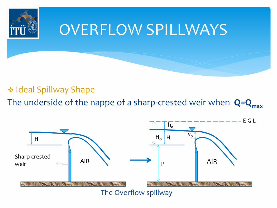
Ideal Spillway Shape
The underside of the nappe of a sharp-crested weir when Q=Qmax
H
Sharp crested weir AIR
H
AIR P
Ho yo
ha
E G L
The Overflow spillway
OVERFLOW SPILLWAYS
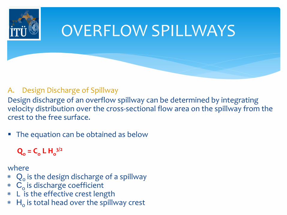
A. Design Discharge of Spillway Design discharge of an overflow spillway can be determined by integrating velocity distribution over the cross-sectional flow area on the spillway from the crest to the free surface. The equation can be obtained as below
Qo = Co L Ho
3/2 where Qo is the design discharge of a spillway Co is discharge coefficient L is the effective crest length Ho is total head over the spillway crest
OVERFLOW SPILLWAYS
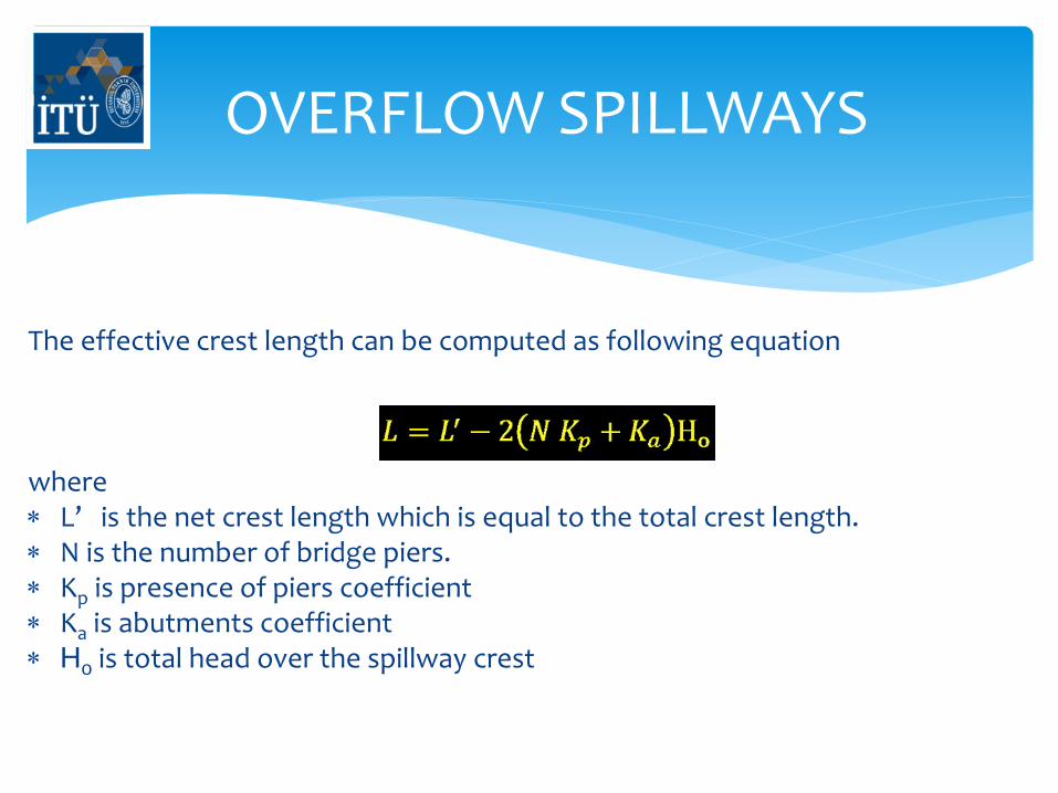
The effective crest length can be computed as following equation where L’ is the net crest length which is equal to the total crest length. N is the number of bridge piers. Kp is presence of piers coefficient Ka is abutments coefficient Ho is total head over the spillway crest
OVERFLOW SPILLWAYS
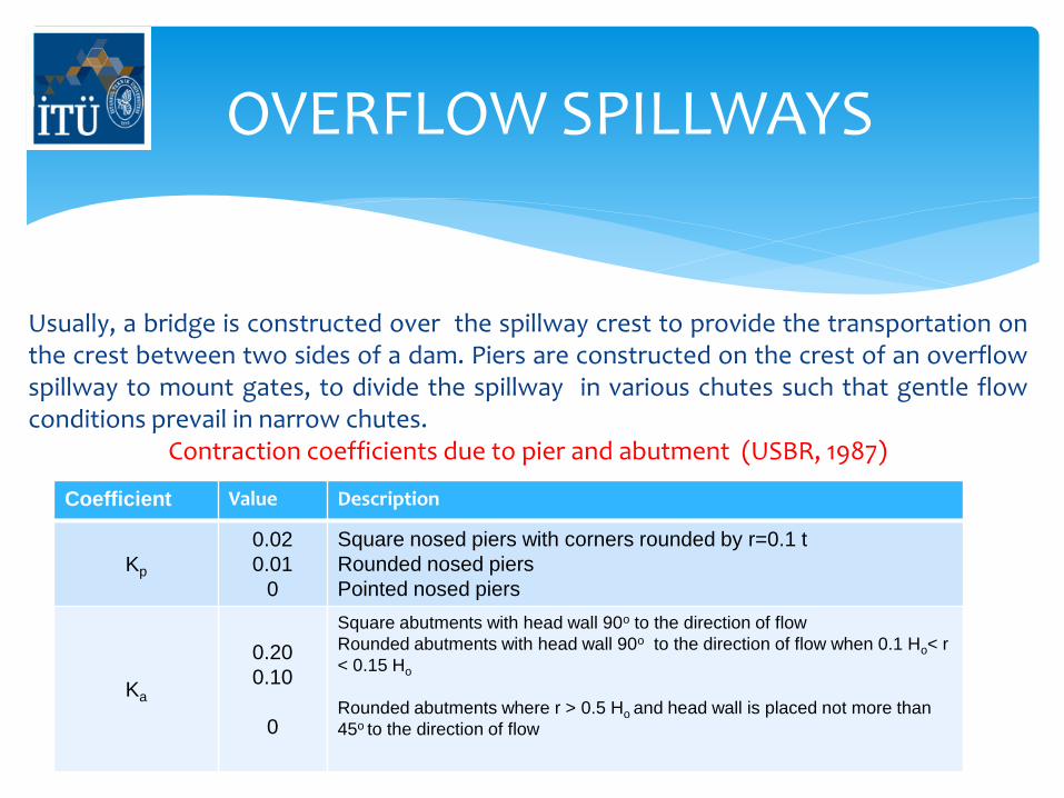
Usually, a bridge is constructed over the spillway crest to provide the transportation on the crest between two sides of a dam. Piers are constructed on the crest of an overflow spillway to mount gates, to divide the spillway in various chutes such that gentle flow conditions prevail in narrow chutes.
Contraction coefficients due to pier and abutment (USBR, 1987)
Coefficient Value Description
Kp
0.02
0.01
0
Square nosed piers with corners rounded by r=0.1 t
Rounded nosed piers
Pointed nosed piers
Ka
0.20
0.10
0
Square abutments with head wall 90o to the direction of flow
Rounded abutments with head wall 90o to the direction of flow when 0.1 Ho< r
< 0.15 Ho
Rounded abutments where r > 0.5 Ho and head wall is placed not more than
45o to the direction of flow
OVERFLOW SPILLWAYS
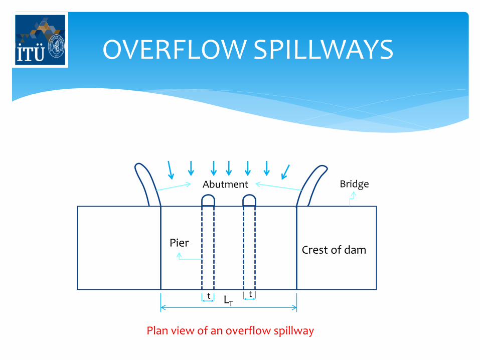
Crest of dam Pier
Abutment
t t LT
Bridge
Plan view of an overflow spillway
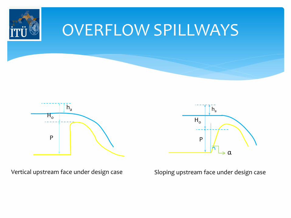
OVERFLOW SPILLWAYS
P
Ho
ha
α
P
Ho
ha
Vertical upstream face under design case Sloping upstream face under design case
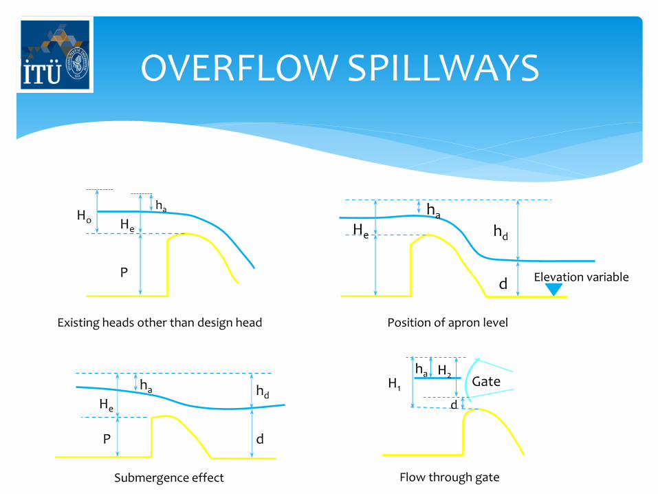
OVERFLOW SPILLWAYS
P
Ho He
ha ha
He hd
d Elevation variable
Existing heads other than design head Position of apron level
d P
He
ha hd
Submergence effect
Gate ha
H1
H2
d
Flow through gate
OVERFLOW SPILLWAYS
Determined from Figures for the vertical overflow spillways as a function of P (spillway height) / Ho (total head)
USE Fig. to modify Co for inclined upstream face.
USE Fig. to obtain Co for heads other than design head.
USE Fig 4.8 to reflect “apron effect” on Co.
USE Fig. to reflect “tailwater effect” on Co.
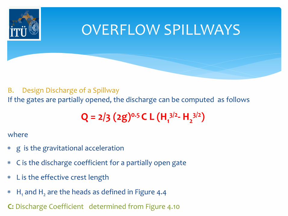
OVERFLOW SPILLWAYS
B. Design Discharge of a Spillway If the gates are partially opened, the discharge can be computed as follows
Q = 2/3 (2g)0.5 C L (H13/2- H2
3/2) where
g is the gravitational acceleration
C is the discharge coefficient for a partially open gate
L is the effective crest length
H1 and H2 are the heads as defined in Figure 4.4
C: Discharge Coefficient determined from Figure 4.10
OVERFLOW SPILLWAYS
CREST GATES
Provide additional storage above the crest
See Fig. 4.11 for Primitive types of gates.
See Fig. 4.11 for Underflow gates.
Common types: radial and rolling
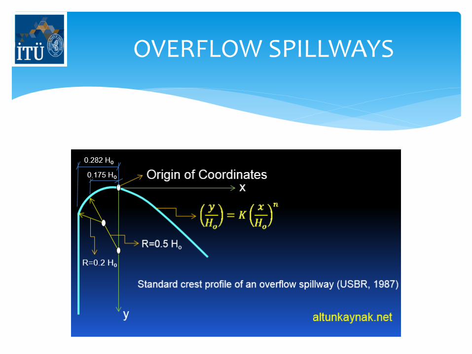
CREST PROFILES
The ideal shape of overflow spillway crest under design conditions
for a vertical upstream face is recommended by USBR (1987)
OVERFLOW SPILLWAYS
OVERFLOW SPILLWAYS
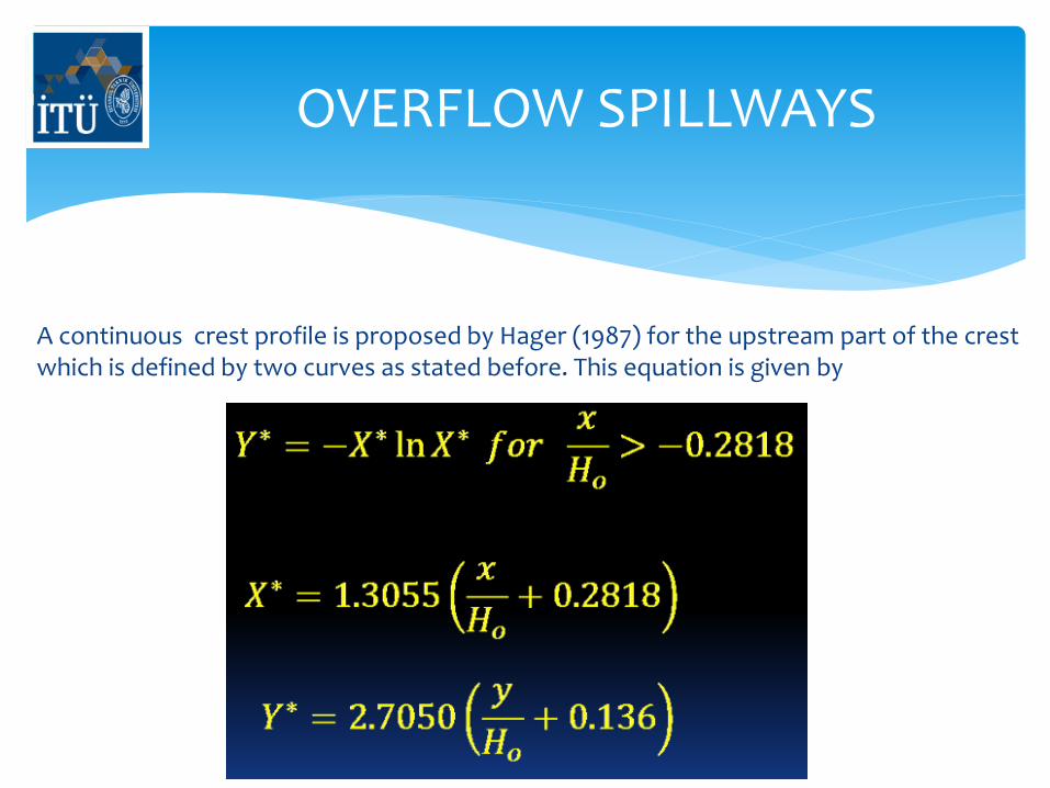
A continuous crest profile is proposed by Hager (1987) for the upstream part of the crest which is defined by two curves as stated before. This equation is given by
OVERFLOW SPILLWAYS
• The values of “K” and “n” in the parabolic relation given in Fig. 4.12 can be determined
from Figure 4.13.
• The pressure distribution on the bottom of the spillway face depends on the
smoothness of the crest profile.
Important Note:
• The upstream face of the crest is formed by smooth curves in order to minimize
the separation
• For a smooth spillway face, the velocity head loss over the spillway can be ignored.
OVERFLOW SPILLWAYS
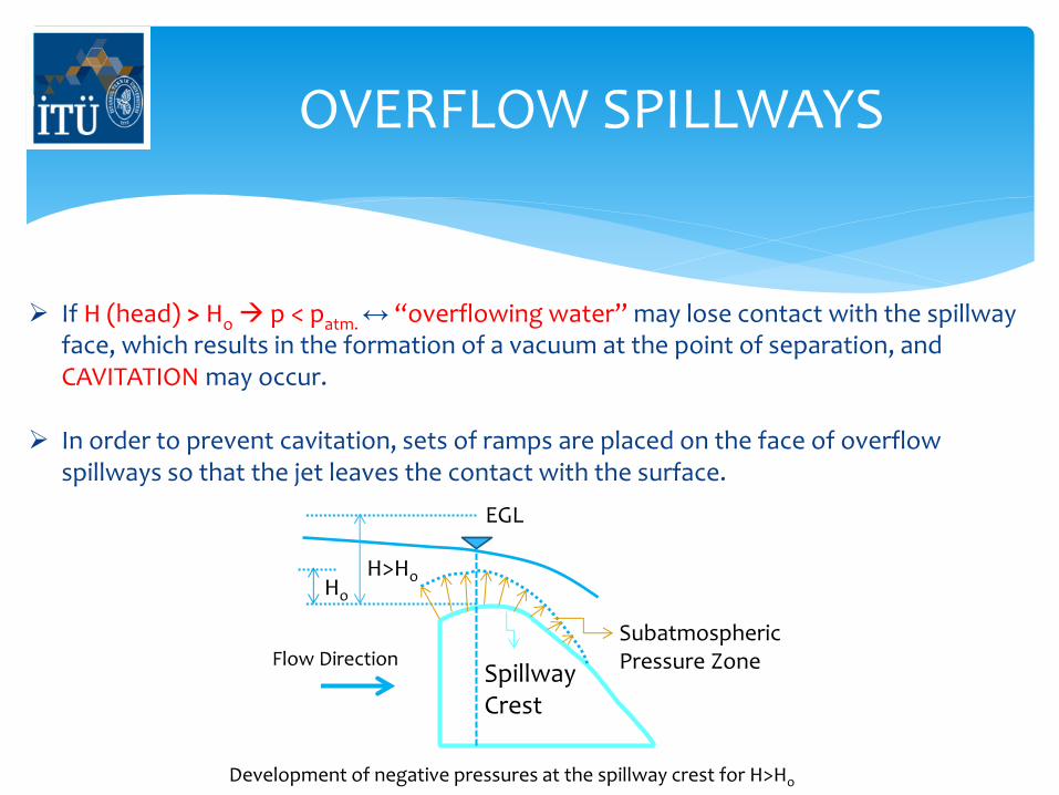
If H (head) > Ho p < patm. ↔ “overflowing water” may lose contact with the spillway face, which results in the formation of a vacuum at the point of separation, and CAVITATION may occur.
In order to prevent cavitation, sets of ramps are placed on the face of overflow spillways so that the jet leaves the contact with the surface.
Subatmospheric Pressure Zone Spillway
Crest
Flow Direction
Ho
H>Ho
EGL
Development of negative pressures at the spillway crest for H>Ho
OVERFLOW SPILLWAYS
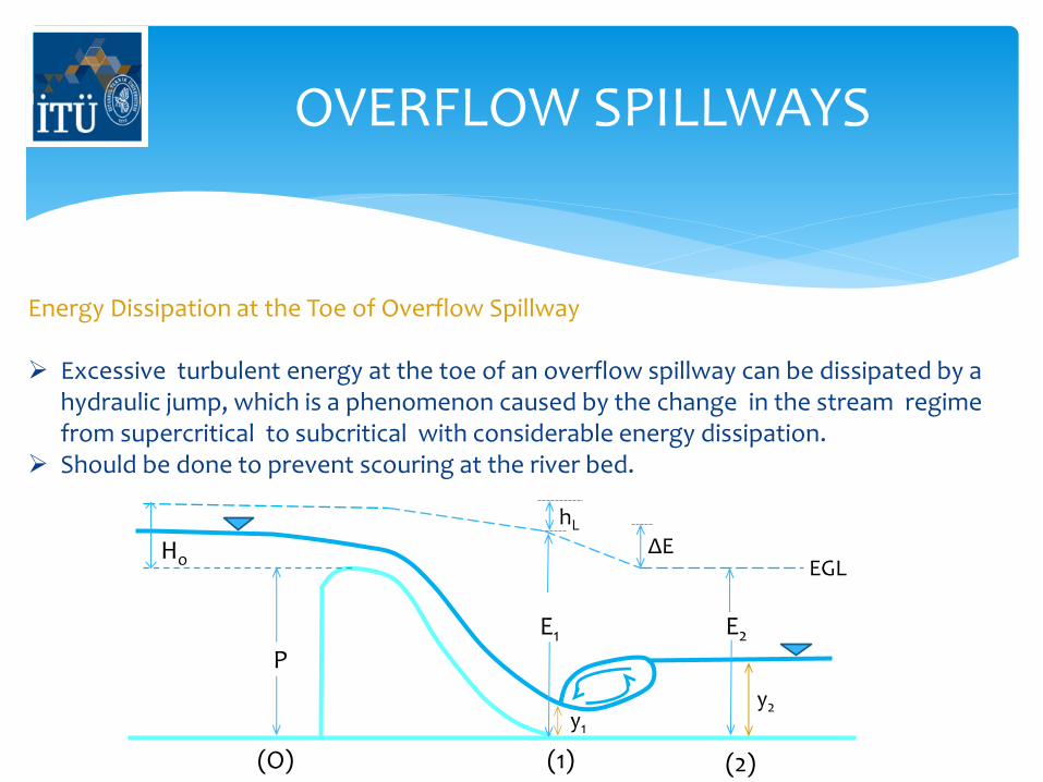
Energy Dissipation at the Toe of Overflow Spillway Excessive turbulent energy at the toe of an overflow spillway can be dissipated by a
hydraulic jump, which is a phenomenon caused by the change in the stream regime from supercritical to subcritical with considerable energy dissipation.
Should be done to prevent scouring at the river bed.
P
E1
y2 y1
E2
Ho
hL
ΔE EGL
(O) (1) (2)
OVERFLOW SPILLWAYS
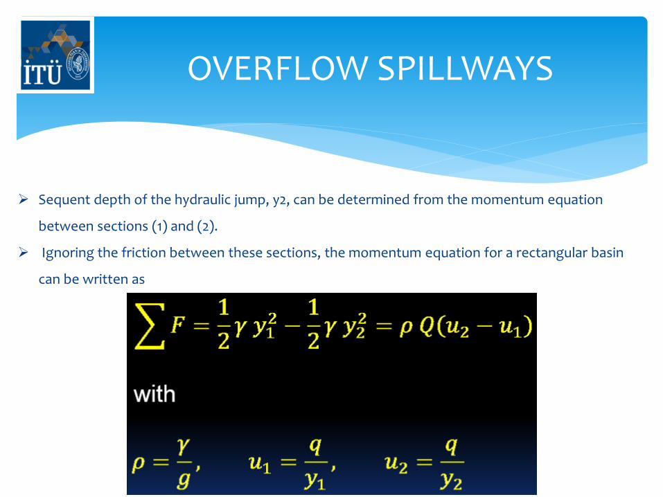
Sequent depth of the hydraulic jump, y2, can be determined from the momentum equation
between sections (1) and (2).
Ignoring the friction between these sections, the momentum equation for a rectangular basin
can be written as
OVERFLOW SPILLWAYS
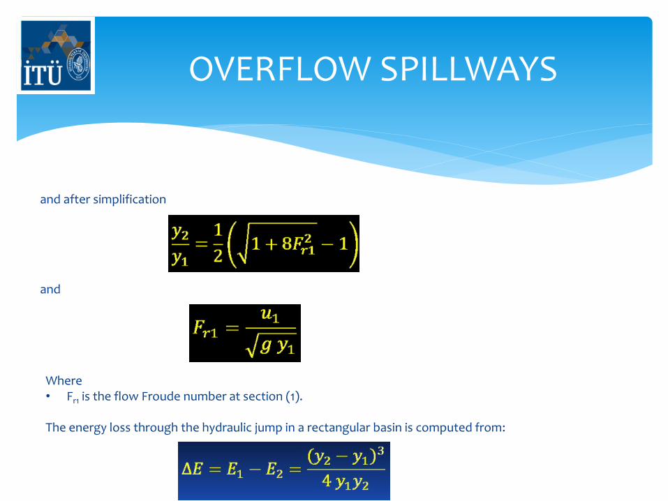
and after simplification
and
Where • Fr1 is the flow Froude number at section (1). The energy loss through the hydraulic jump in a rectangular basin is computed from:
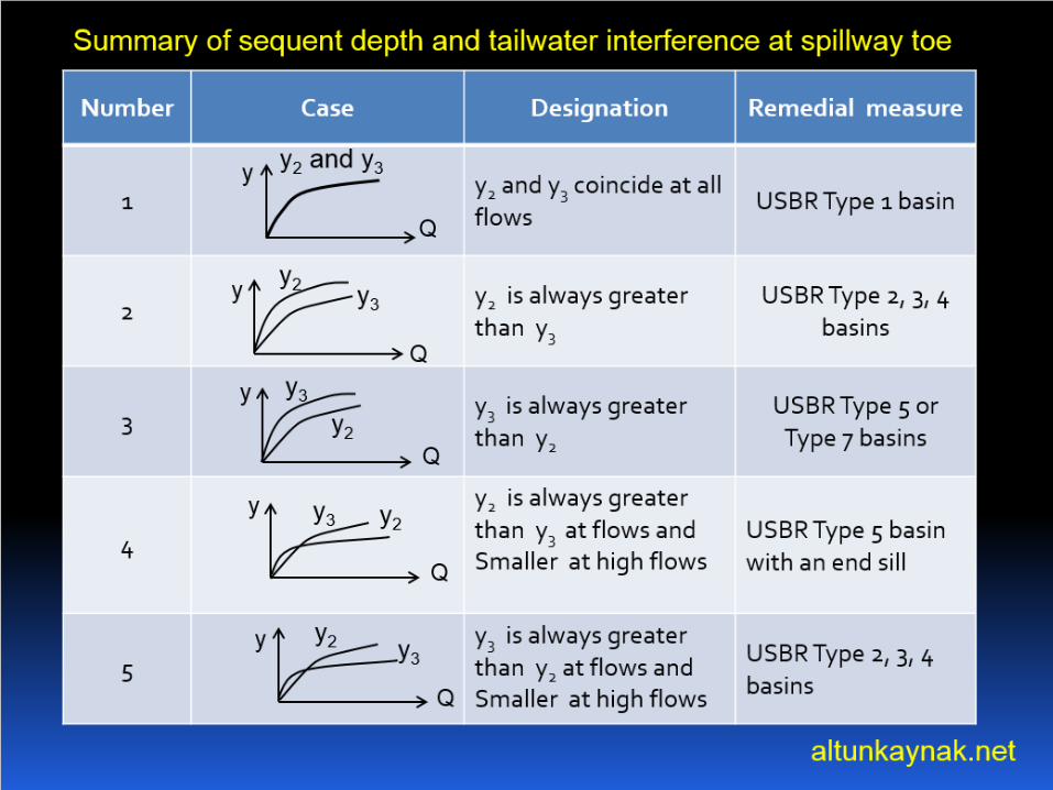
OVERFLOW SPILLWAYS
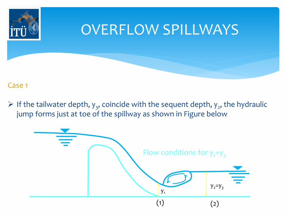
Case 1 If the tailwater depth, y3, coincide with the sequent depth, y2, the hydraulic
jump forms just at toe of the spillway as shown in Figure below
y2=y3 y1
(1) (2)
Flow conditions for y2=y3
OVERFLOW SPILLWAYS
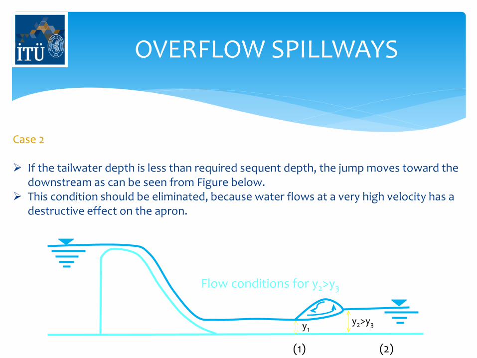
Case 2 If the tailwater depth is less than required sequent depth, the jump moves toward the
downstream as can be seen from Figure below. This condition should be eliminated, because water flows at a very high velocity has a
destructive effect on the apron.
y2>y3 y1
(1) (2)
Flow conditions for y2>y3
OVERFLOW SPILLWAYS
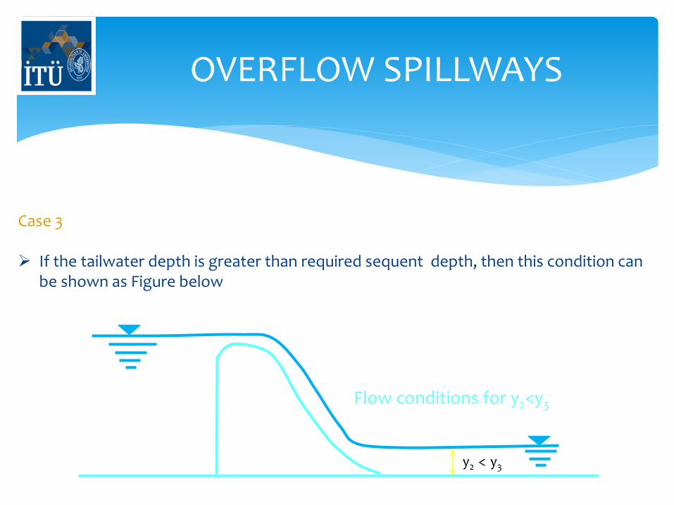
Case 3 If the tailwater depth is greater than required sequent depth, then this condition can
be shown as Figure below
y2 < y3
Flow conditions for y2<y3
OVERFLOW SPILLWAYS
Case 4
Sequent depth of hydraulic jump, y2, is greater than the tailwater depth, y3, at low
flows and is smaller at high flows. USBR type 5 basin with an end sill can be used for
this case.
Case 5
Tailwater depth, y3, is greater than sequent depth, y2, at low flows and is smaller at high
flows. USBR types 2, 3 and 4 basins can be selected for this case.
OVERFLOW SPILLWAYS
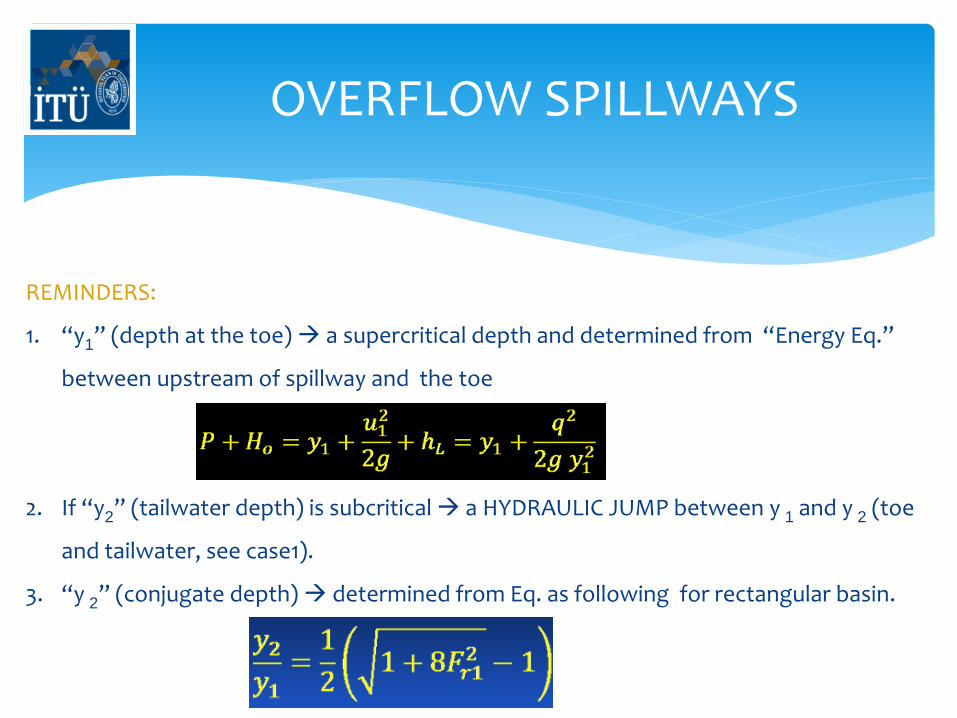
REMINDERS:
1. “y1” (depth at the toe) a supercritical depth and determined from “Energy Eq.”
between upstream of spillway and the toe
2. If “y2” (tailwater depth) is subcritical a HYDRAULIC JUMP between y 1 and y 2 (toe
and tailwater, see case1).
3. “y 2” (conjugate depth) determined from Eq. as following for rectangular basin.
OVERFLOW SPILLWAYS
2) CHUTE SPILLWAYS
In case of having sufficiently stiff foundation conditions at the spillway location, a chute
spillway may replace an overflow spillway due to economic considerations.
A steep sloped open channel is constructed in slabs with 25 to 50 cm thickness having
lengths of approximately 10 m.
3) SIDE CHANNEL SPILLWAYS
If sufficient crest length is not available for overflow or chute spillways in narrow valleys,
flood water is taken in a side channel. Flow conditions in a side channel spillway are given
as below.
OVERFLOW SPILLWAYS
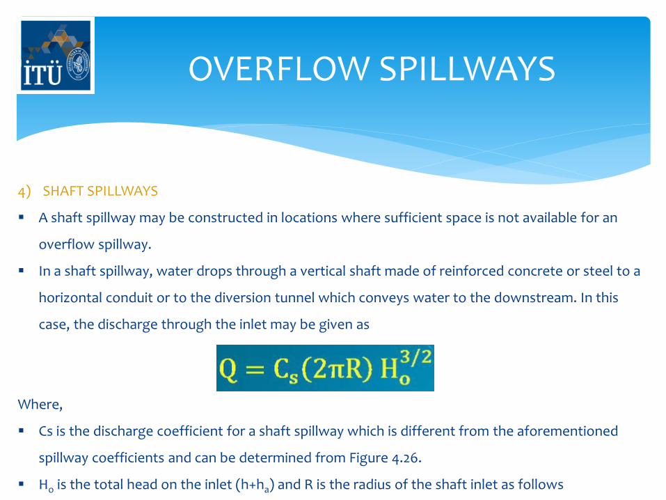
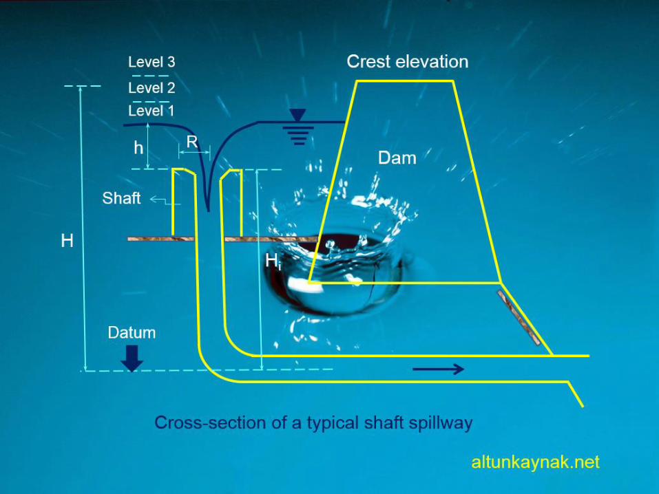
4) SHAFT SPILLWAYS
A shaft spillway may be constructed in locations where sufficient space is not available for an
overflow spillway.
In a shaft spillway, water drops through a vertical shaft made of reinforced concrete or steel to a
horizontal conduit or to the diversion tunnel which conveys water to the downstream. In this
case, the discharge through the inlet may be given as
Where,
Cs is the discharge coefficient for a shaft spillway which is different from the aforementioned
spillway coefficients and can be determined from Figure 4.26.
Ho is the total head on the inlet (h+ha) and R is the radius of the shaft inlet as follows
OVERFLOW SPILLWAYS
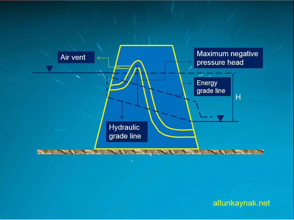
5) Siphon Spillways
A siphon spillway, as demonstrated in next Figure, may be constructed in the
body of a concrete dam at a site where there is no enough space for an
overflow spillway.
Since it is a closed conduit, which has a limited size, its capacity is not as high
as that of an overflow spillway.
Whenever there is enough head at the crown of the siphon, it operates like an
overflow spillway and flow

TEŞEKKÜRLER
Doç. Dr. Abdüsselam ALTUNKAYNAK
www.altunkaynak.net