tahiti dual - fondital.com tahiti... · 3 general information for fitters, maintenance technicians...
TRANSCRIPT
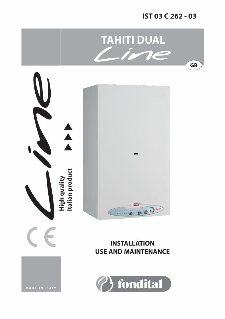
IST 03 C 262 - 03
INSTALLATIONUSE AND MAINTENANCE
TAHITI DUAL
GBH
igh
qu
alit
yIt
alia
n p
rod
uct
M A D E I N I TA Ly

2
Dear Customer,
Thank you for choosing and buying one of our boilers. Please read these instructions carefully in order to install, operate and service the boiler properly.The Manufacturer recommends that Customers contact authorized qualified personnel only for maintenance and repair operations.

3
General information for fitters, maintenance technicians and users
This INSTRUCTION MANUAL, which is an integral and indispensable part of the product, must be handed over to the user by the fitter and must be kept in a safe place for future reference. The manual must accompany the boiler should it be sold or its possession transferred.
This boiler is designed for connection to a central heating system (all models) and to a hot domestic water system (models CTN and CTFS only). Any other use is considered incorrect and therefore dangerous.
The boiler must be installed in compliance with the applicable laws and standards and according to the manufacturer’s instructions given in this manual. Incorrect installation may cause injury to people or animals and damage to property. The manufacturer shall not be held liable for any such injury or damage.
Damage or injury caused by incorrect installation or use, or by failure to follow the manufacturer’s instructions will relieve manufacturer of any and all contractual and extra-contractual liability.
Before installing the boiler, check that the technical data correspond to the requirements for its correct use in the system.
Check that the boiler is intact and has not been damaged during transport and handling. Do not install equipment which is damaged or faulty.
Do not obstruct the air intake or heat dissipation openings.
Only Manufacturer-approved accessories or optional kits must be installed.All the packaging materials can be recycled and must be disposed of correctly. They must be sent to a specific waste management site. Keep the packaging out of the reach of children as it may represent a hazard.
In the event of failure or faulty operation, switch off the boiler. Do not attempt to make any repairs and contact a qualified technician.
Manufacturer-approved parts must be used for all repairs to the boiler.
Failures to comply with the above requirements may affect the safety of the boiler and endanger people, animals and property.
The Manufacturer recommends that Customers contact an authorized Service Centre for maintenance and repairs.
Routine boiler maintenance should be performed according to the schedule in the relevant section of this manual. Appropriate boiler maintenance ensures efficient operation, preservation of the environment, and safety for people, animals and property. Incorrect and irregular maintenance can be a source of danger for people, animals and property.
If the boiler is to remain inactive for a long time, disconnect it from the power mains and close the gas tap. Warning! If the boiler is disconnected from the mains, the electronic anti-freeze function will not operate.
Should there be a risk of freezing, add anti-freeze to the heating system. It is not advisable to empty the system as this may result in damage. Use specific anti-freeze products suitable for multi-metal heating systems.
If you smell gas: •donottouchanyelectricalswitchesanddonotturnonelectricalappliances; •donotigniteflamesandextinguishanycigarettes; •closethemaingastap; •opendoorsandwindows; •contactaServiceCentre,aqualifiedfitterorthegassupplycompany. Never use a flame to detect a gas leak.
WARNING This boiler has been built for installation in the country indicated on packaging and the rating plate. Installation in a country other than the specified one may be a source of danger for people, animals and property.
The Manufacturer cannot be held contractually or extra-contractually liable in the event of failure to comply with the above.

4
RAPID OPERATING INSTRUCTIONS
These instructions can be followed for rapid ignition, regulation and immediate use of the boiler, provided it has been installed by an authorized fitter, started up for the first time and set up for correct operation.
If the boiler is equipped with other accessories, these instructions are not sufficient to ensure correct operation.
Reference must be made to the full instructions for the boiler and all mounted accessories.
For a detailed description of how the boiler operates and safety instructions during operation, refer to the instructions shown in this manual.
1. Open the gas shut-off valve upstream of the boiler.
2. Turn on the main electric switch upstream of the boiler: the green mains light on the control panel (1, pic. 1) comes on.
3. If you do not want to activate the CH function, turn the selector (9, pic. 1) to SUMMER. Only the DHW function is now active.
4. If you want to activate the CH function, turn the selector (9, pic. 1) to WINTER. Both the DHW and CH functions are now active.
5. To regulate the DHW temperature, move the DHW regulation knob (10, pic. 1) to the intermediate position (approx. 45°C). Then regulate as required.
6. To regulate the CH temperature, move the CH regulation knob (11, pic. 1) to 3 o’clock (approx. 70°C). Then regulate as required.
7. Enter the desired room temperature on the thermostat in the room (if present). The boiler is now ready to operate.
If the boiler shuts down, you can restart it by moving the selector (9, pic. 1) to the RESET position for a few seconds and then to the desired position.
Boiler status onSUMMER position
Boiler status onWINTER position
DHW temperatureregulation knob
CH temperatureregulation knob
Mains light
Boiler status onRESET position

5
CONTENTS
Warning page 2
General information for fitters, maintenance technician and users page 3Rapid operating instructions page 4
1. Instructions for the user page 7
1.1 Control panel page 71.2 Operating the boiler page 8 1.2.1 Switching on page 8 1.2.2 Operation page 9 1.2.3 External temperature probe operation (optional) page 101.3 Boiler shut-down page 11 1.3.1 Burner shut-down page 11 1.3.2 Shut-down due to overheating page 11 1.3.3 Shut-down due to incorrect draught (clogging) of the flue system page 11 1.3.4 Shut-down due to low water pressure page 11 1.3.5 Shut-down due to temperature probe malfunction page 111.4 Maintenance page 121.5 Notes for the user page 12
2. Technical characteristics and dimensions page 12
2.1 Technical characteristics page 122.2 Dimensions page 142.3 Plumbing layout and gas connections page 162.4 Operating data page 182.5 General characteristics page 19 3. Instructions for the fitter page 20
3.1 Installation standards page 203.2 Installation page 20 3.2.1 Packaging page 20 3.2.2 Deciding where to install the boiler page 20 3.2.3 Positioning the boiler page 20 3.2.4 Installing the boiler page 22 3.2.5 Boiler room ventilation page 22 3.2.6 Air intake/flue gas system of natural draught boilers page 22 3.2.7 Air intake/flue gas system of forced draught boilers page 23 3.2.7.1 Configuration of air/flue system pipes types: B22, C12, C32, C42, C52, C82 page 24 3.2.7.2 Ø 100/60 diameter coaxial pipe air/flue system page 25 3.2.7.3 Ø 80 mm diameter split pipe air/flue system page 26 3.2.8 Testing boiler efficiency page 28 3.2.8.1 “Chimney sweep” function page 28 3.2.8.2. Checking combustion performance page 29 3.2.9 Gas mains connection page 29 3.2.10 Plumbing connections page 30 3.2.11 Adjustable by-pass page 30 3.2.12 Power mains connection page 30 3.2.13 Room thermostat connection (optional) page 31 3.2.14 Open Therm remote control connection (optional) page 31 3.2.15 External temperature probe installation (optional) and “sliding temperature” operation page 31 3.2.16 Installation of the phone operation device (optional) page 323.3 Loading the system page 323.4 Starting the boiler page 33 3.4.1 Preliminary checks page 33 3.4.2 Switching on and off page 333.5 Wiring layout page 343.6 Adaptation for use with other gases and burner adjustment page 35
4. Testing the boiler page 36
4.1 Preliminary checks page 364.2 Switching on and off page 36
5. Maintenance page 365.1 Maintenance schedule page 365.2 Analysis of combustion parameters page 37
6. Troubleshooting page 38

6
LIST OF PICTURES
pic. 1 - Control panel page 7
pic. 2 - Temperature regulation curves page 10
pic. 3 - Filling tap page 11
pic. 4 - Dimensions mod. CTN and RTN page 14
pic. 5 - Dimensions mod. CTFS and RTFS page 15
pic. 6 - Plumbing diagram for CTN 24 page 16
pic. 7 - Plumbing diagram for CTFS 24/28 page 16
pic. 8 - Plumbing diagram for RTN 24 page 17
pic. 9 - Plumbing diagram for RTFS 24/28 page 17
pic. 10 - Boiler template page 21
pic. 11 - Connection to the chimney for CTN and RTN page 23
pic. 12 - Dimensions for connecting to the flue gas pipe for CTN page 23
pic. 13 - Air intake / flue gas discharge with coaxial ducts (CTFS and RTFS) page 25
pic. 14 - Dimensions for connecting to the coaxial air intake/flue gas discharge pipe (CTFS and RTFS) page 25
pic. 15 - Split kit 0SSDOPPIA03 (CTFS 24 and RTFS 24) page 26
pic. 16 - Split kit 0SSDOPPIA06 (CTFS 28 and RTFS 28) page 26
pic. 17 - Air intake / flue gas discharge with split ducts (CTFS and RTFS) page 27
pic. 18 - Dimensions for connecting to the split air intake/flue gas discharge pipes page 27
pic. 19 - Examples of installation of split air intake / flue gas discharge pipes page 28
pic. 20 - Examples of installation of split air intake / flue gas discharge pipes page 28
pic. 21 - Opening the panel page 28
pic. 22 - “Chimney-sweep” function page 29
pic. 23 - Examples of combustion efficiency measuring points page 29
pic. 24 - Gas mains connection page 29
pic. 25 - Adjustable by-pass page 30
pic. 26 - Installation of the Open Therm remote control page 31
pic. 27 - P6 trimmer position – thermoregulation curves page 32
pic. 28 - Central heating curves in operation with external probe page 32
pic. 29 - Electric layout page 34
pic. 30 - Gas conversion – gas selection jumper page 35
pic. 31 - Gas conversion – gas valve modulation coil page 35
pic. 32 - Gas conversion – pressure test point page 35
pic. 33 - Gas conversion – control panel settings page 35
pic. 34 - Gas conversion – gas valve adjustment page 35
LIST OF TABLES
No. 1 table - Colour displayed by Light in relation to boiler operation status page 8
No. 2 table - Colour displayed by Light in relation to boiler malfunction status page 8
No. 3 table - Calibration data for CTN 24 and RTN 24 page 18
No. 4 table - Calibration data for CTFS 24 and RTFS 24 page 18
No. 5 table - Calibration data for CTFS 28 and RTFS 28 page 18
No. 6 table - General data for each model page 19
No. 7 table - Combustion data for CTN 24 and RTN 24 page 19
No. 8 table - Combustion data for CTFS 24 and RTFS 24 page 19
No. 9 table - Combustion data for CTFS 28 and RTFS 28 page 19
No. 10 table - Relation between temperature (°C) and nominal resistance (Ohm) of CH probe SR and DHW probe SS page 34
7
1. INSTRUCTIONS FOR THE USER
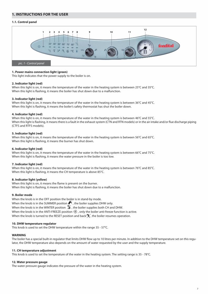
1.1. Control panel
1. Power mains connection light (green)This light indicates that the power supply to the boiler is on.
2. Indicator light (red)When this light is on, it means the temperature of the water in the heating system is between 25°C and 35°C.When this light is flashing, it means the boiler has shut down due to a malfunction.
3. Indicator light (red)When this light is on, it means the temperature of the water in the heating system is between 36°C and 45°C.When this light is flashing, it means the boiler’s safety thermostat has shut the boiler down.
4. Indicator light (red)When this light is on, it means the temperature of the water in the heating system is between 46°C and 55°C.When this light is flashing, it means there is a fault in the exhaust system (CTN and RTN models) or in the air intake and/or flue discharge piping (CTFS and RTFS models).
5. Indicator light (red)When this light is on, it means the temperature of the water in the heating system is between 56°C and 65°C.When this light is flashing, it means the burner has shut down.
6. Indicator light (red)When this light is on, it means the temperature of the water in the heating system is between 66°C and 75°C.When this light is flashing, it means the water pressure in the boiler is too low.
7. Indicator light (red)When this light is on, it means the temperature of the water in the heating system is between 76°C and 85°C.When this light is flashing, it means the CH temperature is above 85°C.
8. Indicator light (yellow)When this light is on, it means the flame is present on the burner.When this light is flashing, it means the boiler has shut down due to a malfunction.
9. Boiler modeWhen the knob is in the OFF position the boiler is in stand-by mode.When the knob is in the SUMMER position , the boiler supplies DHW only.When the knob is in the WINTER position , the boiler supplies both CH and DHW.When the knob is in the ANTI-FREEZE position , only the boiler anti-freeze function is active.When the knob is turned to the RESET position and back , the boiler resumes operation.
10. DHW temperature regulatorThis knob is used to set the DHW temperature within the range 35 - 57°C.
WARNINGThe boiler has a special built-in regulator that limits DHW flow up to 10 litres per minute. In addition to the DHW temperature set on this regu-lator, the DHW temperature also depends on the amount of water requested by the user and the supply temperature.
11. CH temperature adjustmentThis knob is used to set the temperature of the water in the heating system. The setting range is 35 - 78°C.
12. Water pressure gaugeThe water pressure gauge indicates the pressure of the water in the heating system.
pic. 1 - Control panel
1 2 3 4 5 6 7 8 9 10 1112

8
COLOUR DISPLAy ACCORDING TO BOILER STATUS
Regular Working LIGHT 1 LIGHT 2 LIGHT 3 LIGHT 4 LIGHT 5 LIGHT 6 LIGHT 7 LIGHT 8
Power connected to boiler Green n/a n/a n/a n/a n/a n/a n/a
Burner on Green n/a n/a n/a n/a n/a n/a yellow
CH temperature < 25°C Green OFF OFF OFF OFF OFF OFF n/a
26°C < CH temperature < 35°C Green Red OFF OFF OFF OFF OFF n/a
36°C < CH temperature < 45°C Green OFF Red OFF OFF OFF OFF n/a
46°C < CH temperature < 55°C Green OFF OFF Red OFF OFF OFF n/a
56°C < CH temperature < 65°C Green OFF OFF OFF Red OFF OFF n/a
66°C < CH temperature < 75°C Green OFF OFF OFF OFF Red OFF n/a
76°C < CH temperature < 85°C Green OFF OFF OFF OFF OFF Red n/a
No. 1 table – Colour displayed by Light in relation to boiler operation status
Malfunction LIGHT 1 LIGHT 2 LIGHT 3 LIGHT 4 LIGHT 5 LIGHT 6 LIGHT 7 LIGHT 8
Power is missing OFF OFF OFF OFF OFF OFF OFF OFF
Safety thermostat shutdown Green OFF Red L OFF OFF OFF OFF OFF
Flue gas thermostat shutdown (CTN)Air/flue gas pressure switch shutdown (CTFS)
Green OFF OFF Red L OFF OFF OFF OFF
Shutdown due to flame absence Green OFF OFF OFF Red L OFF OFF OFF
Water pressure switch shutdown Green OFF OFF OFF OFF Red L OFF OFF
Gas valve alarm Green OFF Red L OFF OFF OFF OFF yellow L
Water temperature switch alarm (>85 °C) Green OFF OFF OFF OFF OFF Red L OFF
DHW flow probe alarm Green Red L OFF OFF OFF OFF OFF OFF
CH flow probe alarm Green Red L OFF OFF OFF OFF OFF yellow L
Externalcylinderprobealarm Green Red LA OFF OFF OFF OFF OFF yellow LA
Remote control malfunction Green OFF OFF Red L OFF OFF OFF yellow L
No. 2 table – Colour displayed by Light in relation to boiler malfunction status
KEy TO ACRONyMSOFF LIGHT offRED LIGHT on, displaying the colour shown on the tableL RED LIGHT or lights flashing, displaying the colour shown on the tableLA RED LIGHTS flashing, displaying in sequence the colours shown on the tablen/a LIGHT status not relevant
1.2. Operating the boiler
1.2.1. Switching on
These instructions presuppose that the boiler has been installed by an authorized fitter, started up for the first time and set up for correct operation.
• Open the gas stop cock.• Connect the boiler to the mains power supply (LIGHT 1 on the control panel comes on).• Choose boiler mode by operating the “OFF/SUMMER/WINTER/ANTI-FREEZE” selector (9).• Turn the CH temperature adjustment knob (11) to set the temperature required for the heating system.• Turn the DHW temperature knob (10) to set the temperature required for the DHW (CTN, CTFS).• Set the room temperature on the thermostat, if there is one.
WARNING: If the boiler is not used for a long time, particularly if it runs on LPG, ignition may be difficult.Before operating the boiler, switch on another gas-powered device (e.g. kitchen range or oven). Be aware that even if this procedure isfollowed,theboilermaystillexperiencesomestartingdifficultiesandshutdownonceortwice.Reset the boiler by operating knob (9), then turn the knob back to the required position.

9
1.2.2. Operation
CENTRAL HEATINGUse the regulation knob (11, pic. 1) to set the temperature in the central heating system.The temperature setting range is 35-78°C (from the counter-clockwise limit position to the time limit position). The CH temperature can be read from lights 2÷7 (pic. 1) on the control panel.
To prevent frequent ignition and switching off in heating mode, the boiler has a 4-minute waiting time between subsequent ignitions.If the water temperature in the system fall below 40°C, waiting procedure is aborted and the boiler re-ignites (Antifast function).
DHWThe domestic hot water supply function is active on models CTN and CTFS, and on models RTN and RTFS with an (optional) external water heater. This function always has priority over central heating water.
For models CTN and CTFS, the temperature setting range is 35-57°C (from the counter-clockwise limit position to the time limit of regulation knob 10). For models RTN and RTFS with an (optional) external water heater with an NTC probe (10 kΩ @ β=3435; refer to the water heater specifica-tions), the temperature setting range is 35-57°C (from the counter-clockwise limit position to the time limit of regulation knob 10). For models RTN and RTFS with an (optional) external water heater with thermostat probe, the desired HDW temperature must be set on the water heater (refer to the attached instructions). Regulation knob 10 has no effect on this configuration.
The boiler is fitted with a flow-limiting device that allows a maximum DHW flow of 10 litres per minute.The DHW flow rate depends on the boiler’s thermal capacity and the mains water supply temperature, and can be calculated from the fol-lowing formula: Kl = DHW litres per min. = --- ΔTK represents:- 334 (CTN 24)- 341 (CTFS 24)- 410 (CTFS 28)ΔT = DHW temperature – mains water supply temperature
E.g. In model CTFS 24, if the mains water supply temperature is 8°C and DHW is required at 38°C, the value of ΔT is:ΔT = 38°C – 8°C = 30°Cand DHW litres (l per minute) available at the required temperature of 38°C is
I = 341 / 30 = 11.4 [litres per minute - mixed water to the tap]
ANTI-FREEZE
This boiler is fitted with an anti-freeze protection system, which works when the following functions are activated: SUMMER, WINTER and ANTI-FREEZE.
The anti-freeze function only protects the boiler, not the whole heating system. The heating system must be protected using a room thermostat, although this is disabled when the selector is set to the ANTI-FREEZE or OFF mode.
Therefore, if you want to protect both the boiler and the system, turn to WINTER mode on selector 9.
When the heating water temperature sensor detects a water temperature of 5°C, the boiler switches on and stays on at its minimum thermal power until the temperature reaches 30°C or 15 minutes have elapsed. The pump continues to operate even if the boiler shuts down.
In models CTN and CTFS, anti-freeze function also protects the DHW circuit.
When the DHW temperature sensor detects a temperature of 5°C, the boiler switches on and stays on at its minimum thermal power until the temperature reaches 10°C or 15 minutes have elapsed (the deviating valve is in the DHW position). The pump continues to operate even if the boiler shuts down.

10
In boilers with an external heater for the supply of domestic hot water, which have a thermostat-type temperature sensor, the anti-freeze function does NOT protect the water heater. It can be protected by setting the boiler to Summer or Winter , or by setting a value above 0°C on the water heater thermostat.
In CH boilers with an external water heater for the supply of domestic hot water, which have an NTC temperature sensor (10 kΩ @ β=3435; refer to the boiler specifications), the anti-freeze function protects the water heater as well.
When the external cylinder temperature sensor detects a water temperature of 5°C, the boiler switches on and stays on at its minimum thermal power until the temperature of the water in the external cylinder reaches 10°C or 15 minutes have elapsed. The pump continues to operate even if the boiler shuts down.
The CH system can be protected effectively against freezing by means of specific anti-freeze additives suitable for use in multi-metal systems.Do not use car engine anti-freeze products, and periodically check the effectiveness of the anti-freeze product.
PUMP ANTI-BLOCKING FUNCTION AND DEVIATING VALVE
If the boiler remains inactive for long time and• knob 9 is not on OFF, • the boiler is not electrically disconnected from the mains,the circulation pump (for all models) and the deviating valve (for models CTN and CTFS only) are automatically activated for a while every 24 hours to prevent them from blocking.
1.2.3.Externaltemperatureprobeoperation(optional)
The boiler can be equipped with an (optional) external temperature probe, by means of which the boiler adjusts the CH water temperature according to the outdoor temperature, in other words, increasing the CH water temperature when the outdoor temperature decreases, and vice-versa. This increases energy-saving operation (this boiler mode is called “sliding temperature operation”).
The boiler microprocessor program determines CH water temperature variations.
When an external temperature probe is connected to the boiler, the CH water temperature adjusting knob (11, pic. 1) loses its function and becomes a room temperature control device.
When knob 11 is turned fully counter-clockwise, the room temperature setting is 15°C; when set to 9 o’clock, the temperature is 18°C; when set to 12 o’clock, the temperature is 25°C; when set to 3 o’clock the temperature is 32°C; when it is turned fully clockwise the temperature is 35°C.For the best curve setting, it is advisable to set the temperature at around 20°C.
Picture 2 shows the curves for af room temperature of 20°C. As this value is increased via the regulation knob 11, the curves move upwards. With this setting, if for example you select the curve corresponding to coefficient 1, with an outdoor temperature of -4°C, the flow temperatu-re will be 50°C.
Refer to subsection 3.2.15 for detailed sliding temperature operation.
pic. 2 - Temperature regulation curves External temperature (°C)
CH
flow
tem
per
atur
e (°
C)
Ther
mor
egul
atio
n cu
rves
co
effici
ent
11
1.3. Boiler shut-down
If a malfunction occurs, the boiler automatically shuts down.Refer to tables 1 and 2 for boiler status.In order to determine the probable causes of the malfunction, refer to section 6 - Troubleshooting - at the end of this manual (in addition to tables 1 and 2). Follow the procedure described for the type of shut-down.
1.3.1. Burner shut-down
When the burner shuts down because the flame has gone out, light 5 (red) starts flashing. If this happens, proceed as follows.
• Check that the gas stopcock is open, and make sure the gas main is actually providing service by lighting a gas-powered kitchen appliance such as a kitchen range or oven.• Once the presence of gas has been verified, reset the burner by turning knob 9 to the RESET position for 2 seconds, and then to the desired operating mode. If the boiler does not shut down, and you have performed the reset procedures three times, contact an authorized Service Centre or a qualified service engineer.
Should frequent burner shut-down occur, a recurrent malfunction may be present. Contact an authorized Service Centre or a qualified service engineer.
1.3.2. Shut-down due to overheating
When the CH water gets too hot, the boiler shuts down, and light 3 (red) starts flashing.If this happens, contact an authorized Service Centre or a qualified service engineer.
1.3.3. Shut-down due to incorrect draught (clogging) of the flue system
If the burner shuts down due to a malfunction of the flue system (models CTN and RTN ) or the air intake and/or flue discharge piping (models CTFS or RTFS), light 4 starts to flash. If this happens, contact a Service Centre or a qualified service engineer.
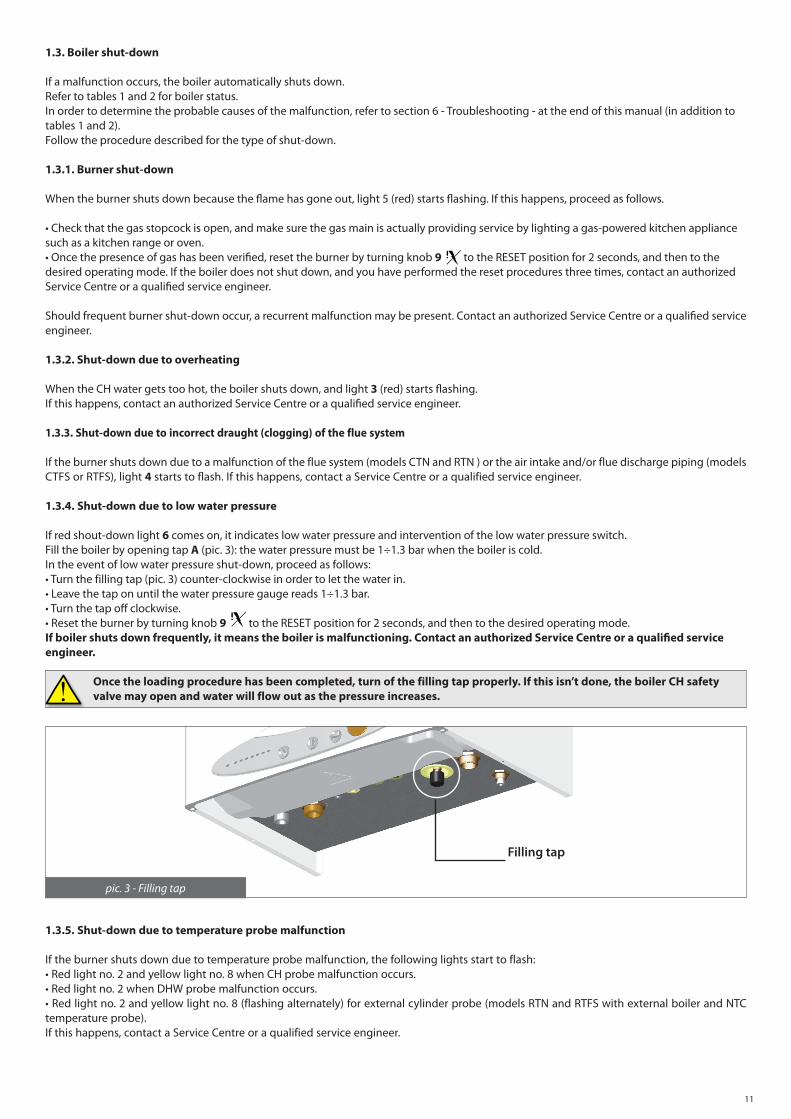
1.3.4. Shut-down due to low water pressure
If red shout-down light 6 comes on, it indicates low water pressure and intervention of the low water pressure switch.Fill the boiler by opening tap А (рiс. 3): the water pressure must be 1÷1.3 bar when the boiler is cold.In the event of low water pressure shut-down, proceed as follows:• Turn the filling tap (pic. 3) counter-clockwise in order to let the water in.• Leave the tap on until the water pressure gauge reads 1÷1.3 bar.• Turn the tap off clockwise.• Reset the burner by turning knob 9 to the RESET position for 2 seconds, and then to the desired operating mode.If boiler shuts down frequently, it means the boiler is malfunctioning. Contact an authorized Service Centre or a qualified service engineer.
Once the loading procedure has been completed, turn of the filling tap properly. If this isn’t done, the boiler CH safety valve may open and water will flow out as the pressure increases.
1.3.5. Shut-down due to temperature probe malfunction
If the burner shuts down due to temperature probe malfunction, the following lights start to flash:• Red light no. 2 and yellow light no. 8 when CH probe malfunction occurs.• Red light no. 2 when DHW probe malfunction occurs.• Red light no. 2 and yellow light no. 8 (flashing alternately) for external cylinder probe (models RTN and RTFS with external boiler and NTC temperature probe).If this happens, contact a Service Centre or a qualified service engineer.
Filling tap
pic. 3 - Filling tap

12
1.4. Maintenance
Routine boiler maintenance must be provided according to the applicable laws in the country of installation and following the instructions given in the relevant section in this manual. Correct maintenance ensures that the boiler operates efficiently, is environmentally friendly, and is not a danger to people, animals or property.By law, only qualified personnel are allowed to service the boiler.The Manufacturer recommends that Customers contact an authorized Service Centre for maintenance and repairs.For maintenance interventions, refer to section 5 – Maintenance.
Theexternalboilerhousingmustonlybecleanedwithstandardhouseholdcleaningproducts.Do not use water!
1.5. Notes for the user
The user may only access boiler parts that can be reached without using any technical equipment or tools. The user is not authorized to remove the boiler housing or touch any of the internal parts.No one, including qualified service engineers, is authorized to modify the boiler.
The manufacturer can not be held liable for damage to people, animals, or property due to tampering or improper work done to the boiler.
If the boiler remains inactive and the power supply disconnected for a long time, the pump may not operate.Pump servicing includes removing the boiler housing and accessing the internal parts of the boiler, so this must only be done by a qualified service engineer.Pump blockage can be avoided by adding to the water filming additives suitable for multi-metal systems.
2. TECHNICAL CHARACTERISTICS AND DIMENSIONS
2.1. Technical characteristics
The boiler is equipped with an atmospheric burner. All versions are equipped with electronic ignition and ionization flame control.
The following models of boiler are available:
- CTN 24: open chamber and natural draught, electronic ignition and instant DHW supply (23.31 kW)- RTN 24: open chamber and natural draught, electronic ignition, CH supply only (23.31 kW)- CTFS 24: sealed chamber and forced draught, electronic ignition and instant DHW supply (23.77 kW)- RTFS 24: sealed chamber and forced draught, electronic ignition, CH supply only (23.77 kW)- CTFS 28: sealed chamber and forced draught, electronic ignition and instant DHW supply (28.6 kW)- RTFS 28: sealed chamber and forced draught, electronic ignition, CH supply only (28.6 kW)
All models comply with the Directives issued in the country of destination indicated in the rating plate.Installation in a country other than the specified one may be a source of danger for people, animals and property.
The main technical characteristics of the boiler are listed below:
Construction characteristics- IPX4D electrically protected control panel- Modulating electronic safety board- Electronic ignition with external separate transformer and ionization flame detection- Stainless steel multi-gas atmospheric burner- Modulating gas valve with double shutter- Mono-thermal, high performance, copper heat exchanger- Stainless steel DHW heat exchanger (models CTN and CTFS)- Motorized deviating valve (models CTN and CTFS)- Three-speed circulation pump, equipped with a de-aerator - Low water safety pressure switch- 8-litre expansion vessel- DHW priority flow switch (models CTN and CTFS)- 10 litres/min DHW flow limiting device (models CTN and CTFS)- Adjustable by-pass- Boiler filling and draining taps- CH (all models) and DHW (models CTN and CTFS) temperature probes- Safety limit thermostat- Flue thermostat (models TN)- Flue pressure switch (models TFS)

13
User interface- RESET, STAND-By, SUMMER/WINTER, SUMMER and ANTI-FREEZE function selector- CH temperature switch (35 -78°C)- DHW temperature switch for models C and R equipped with external cylinder and NTC temperature probe (35 - 57°C)- Leds indicating water temperature- Water pressure gauge- Lights indicating: • Mains power connection • Flame presence • Burner shut-down • Burner shut-down due to overheating • Burner shut-down due to incorrect flue draught (models TN) • Burner shut-down due to flue pressure switch intervention (models TFS) • Low water pressure • CH or DHW temperature probe fault • Remote control connection fault
Operating characteristics- CH mode electronic flame modulation, timer-controlled flame rising ramp (50 seconds)- DHW mode electronic flame modulation, timer-controlled flame rising ramp (for models C and R equipped with external cylinder and NTC temperature probe)- DHW priority function- CH flow anti-freeze function (ON: 5°C, OFF: 30°C or after 15 min. operation)- DHW flow anti-freeze function (ON: 5°C, OFF: 10°C or after 15 min. operation; for models C and R equipped with external cylinder and NTC temperature probe)- External boiler anti-freeze function (ON: 5°C, OFF: 10°C or after 15 min. operation; only for model R equipped with external cylinder and NTC temperature probe)- “Anti–Legionnaires’ disease ” function (only for model R equipped with external cylinder and NTC temperature probe)- Timer-controlled “chimney sweep” function (15 minutes)- Flame propagation function during ignition- CH max heat output adjusting trimmer- Ignition heat output adjusting trimmer- Timer-controlled room thermostat (240 seconds when CH flow temperature > 40°C)- Pump post-circulation function in CH, anti-freeze or chimney sweep mode (180 seconds)- Pump post-circulation function in DHW (30 seconds)- CH temperature post-circulation function: > 85°C: 30 seconds- Safety post-circulation function (ON: 95°C; OFF: 90°C – models TFS)- Pump and deviating valve anti-locking function (180 seconds operation after 24 hours of boiler inactivity)- Can be connected to a room thermostat (optional)- Can be connected to an external temperature probe (optional supplied by the Manufacturer)- Can be connected to an Open Therm remote control (optional supplied by the Manufacturer)- Can be connected to a cylinder timer connection (only for model R equipped with external cylinder and NTC temperature probe)

14
2.2. Dimensions
G
450
750
325
131
218232
138 17
7
43 56 98 75 98 80
CF R
MG
RS
RC
SV
G Gas intakeM CH flowC DHW flow (CTN only)F Mains water intakeR CH returnRC Filling tapRS Discharge tapSV 3bar safety valve discharge tap
CTN and RTN models
bottom view top view
pic. 4 - Dimensions mod. CTN and RTN

15
450
750
325
134
120 85
165
85
138 17
7
43 56 98 75 98 80
G M
CF R
RCRS
165
SV
G Gas intakeM CH flowC DHW flow (CTFS only)F Mains water intakeR CH returnRC Filling tapRS Discharge tapSV 3bar safety valve discharge tap
CTFS and RTFS models
pic. 5 - Dimensions mod. CTFS and RTFS
bottom view top view

16
2.3. Plumbing layout and gas connections
1. DHW temperature probe2. Gas valve3. CH temperature probe4. Burner nozzles5. Burner6. Ignition electrode7. Safety thermostat8. Secondary heat exchanger plate9. Extractor hood10. Flue gas safety thermostat11. De-aerator12. Flame detection electrode13. Expansion vessel14. Pump15. Filling tap16. Water pressure switch17. Safety valve18. DHW flow limiting device (max. 10 litres /minute)19. Flow switch20. Mains water inlet filter
G Gas intakeM CH flowC DHW flowF Mains water intakeR CH return
1. DHW temperature probe2. Gas valve3. CH temperature probe4. Burner nozzles5. Burner6. Ignition electrodes7. Safety thermostat8. Mono-thermal heat exchanger9. Sealed combustion chamber10. Flue gas extraction fan11. Flue gas pressure test point12. Flue gas pressure safety switch13. Air intake/flue gas pipe14. Flue gas pressure test point15. Flame detection electrode16. Expansion vessel17. De-aerator18. Pump19. Filling tap20. Water pressure switch21. Safety valve22. DHW flow limiting device (max. 10 litres /minute)23. Flow switch24. Mains water inlet filter25. Secondary heat exchanger plate26. Adjustable by-pass27. Three-way valve
G Gas intakeM CH flowC DHW flowF Mains water intakeR CH return
CTN 24
2
3
4
5
7
8
1
109
6
11
13
14
16
15
17181920
12
pic. 6 - Plumbing diagram for CTN 24
CTFS 24/28
1
13
2
3
45
6
7
89
10
11
12
14
15
17
16
18
20
19
222324
25
26
27
21
pic. 7 - Plumbing diagram for CTFS 24/28
17
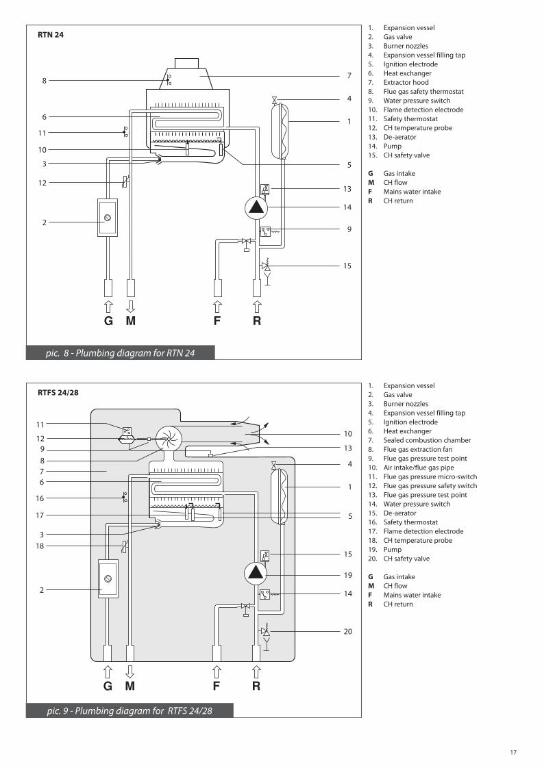
RTN 241. Expansion vessel2. Gas valve3. Burner nozzles4. Expansion vessel filling tap5. Ignition electrode6. Heat exchanger7. Extractor hood8. Flue gas safety thermostat9. Water pressure switch10. Flame detection electrode11. Safety thermostat12. CH temperature probe13. De-aerator14. Pump15. CH safety valve
G Gas intakeM CH flowF Mains water intakeR CH return
2
12
3
11
6
87
4
1
5
10
13
14
9
15
RTFS 24/281. Expansion vessel2. Gas valve3. Burner nozzles4. Expansion vessel filling tap5. Ignition electrode6. Heat exchanger7. Sealed combustion chamber8. Flue gas extraction fan9. Flue gas pressure test point10. Air intake/flue gas pipe11. Flue gas pressure micro-switch12. Flue gas pressure safety switch13. Flue gas pressure test point14. Water pressure switch15. De-aerator16. Safety thermostat17. Flame detection electrode18. CH temperature probe19. Pump20. CH safety valve
G Gas intakeM CH flowF Mains water intakeR CH return
2
5
183
16
678
9
11
1210
13
4
1
17
15
19
14
20
pic. 8 - Plumbing diagram for RTN 24
pic. 9 - Plumbing diagram for RTFS 24/28

18
2.4. Operating data
Burner pressures must be checked after the boiler has been operating for three minutes.
CTN 24 - RTN 24
Gas typeMax.heat
inputMax.heat
output Min. heat
output Mains gas pressure
Nozzle diameter
Burner pressure
(kW) (kW) (kW) (mbar) (mm) (mbar)min max
Natural gas G 20 25.7 23.31 9.85 20 1.25 2.5 13.0
Butane gas G 30 25.7 23.31 9.85 29 0.77 5.3 27.0
Propane gas G 31 25.7 23.31 9.85 37 0.77 6.6 35.5
No. 3 table - Calibration data for CTN 24 and RTN 24
Hot water supply ∆T 45°C = 7.4 l/minHot water supply ∆T 40°C = 8.4 l/minHot water supply ∆T 35°C = 9.6 l/min
Hot water supply ∆T 30°C = 11.1 l/min *Hot water supply ∆T 25°C = 13.4 l/min **mixedwatertothetap
CTFS 24 - RTFS 24
Gas typeMax.heat
inputMax.heat
output Min. heat
output Mains gas pressure
Nozzle diameter
Burner pressure
(kW) (kW) (kW) (mbar) (mm) (mbar)min max
Natural gas G 20 25.5 23.77 9.9 20 1.25 2.5 13.5
Butane gas G 30 25.5 23.77 9.9 29 0.77 5.3 27
Propane gas G 31 25.5 23.77 9.9 37 0.77 6.6 35.5
No. 4 table - Calibration data for CTFS 24 and RTFS 24
Hot water supply ∆T 45°C = 7.6 l/minHot water supply ∆T 40°C = 8.5 l/minHot water supply ∆T 35°C = 9.7 l/min
Hot water supply ∆T 30°C = 11.4 l/min *Hot water supply ∆T 25°C = 13.6 l/min **mixedwatertothetap
CTFS 28 - RTFS 28
Gas typeMax.heat
inputMax.heat
output Min. heat
output Mains gas pressure
Nozzle diameter
Burner pressure
(kW) (kW) (kW) (mbar) (mm) (mbar)min max
Natural gas G 20 30.5 28.6 12.3 20 1.35 2.6 12.0
Butane gas G 30 30.5 28.6 12.3 29 0.80 4.7 28.9
Propane gas G 31 30.5 28.6 12.3 37 0.80 6 33.4
No. 5 table - Calibration data for CTFS 28 and RTFS 28
Hot water supply ∆T 45°C = 9.1 l/minHot water supply ∆T 40°C = 10.2 l/min*Hot water supply ∆T 35°C = 11.7 l/min*
Hot water supply ∆T 30°C = 13.7 l/min *Hot water supply ∆T 25°C = 16.4 l/min **mixedwatertothetap

19
2.5. General characteristics
CTN 24 RTN 24 CTFS 24 RTFS 24 CTFS 28 RTFS 28
Category - II2H3+ II2H3+ II2H3+
Burner nozzles no. 12 12 13
Minimum CH flow rate l/h 550 550 670
Minimum CH pressure bar 0.5 0.5 0.5
Maximum CH pressure bar 3 3 3
Minimum DHW pressure bar 0.3 - 0.3 - 0.3 -
Maximum DHW pressure bar 8 - 8 - 8 -
DHW specific capacity (∆t 30 °C) l/min 11.1 - 11.4 - 13.7 -
Electrical power supply – voltage / frequency V ~ Hz 230 ~ 50 230 ~ 50 230 ~ 50
Power mains supply fuse A 2 2 2
Maximum power consumption W 90 130 150
Net weight kg 36.5 34.5 40.3 38.0 41.0 38.5
Natural gas consumption (*) m3/h 2.72 2.70 3.23
Butane gas consumption kg/h 2.02 2.01 2.40
Propane gas consumption kg/h 1.99 1.98 2.36
Maximum CH working temperature °C 83 83 83
Maximum DHW working temperature °C 62 - 62 - 62 -
Total capacity of expansion vessel l 8 8 8
Maximum recommended CH system capacity (**) l 160 160 160
No. 6 table - General data for each model
(*) Value related to 15°C – 1013 mbar condition(**) Maximum water temperature of 83°C, expansion vessel pressure 1 bar
CTN 24 - RTN 24 maxheatoutput min heat output 30% heat output
Boiler casing heat loss % 0.8 0.8 -
Flue system heat loss with burner on % 8.5 9.7 -
Flue system mass capacity g/s 16.2 13.7 -
Flue temp.– air temp. °C 85 50 -
CO2
% 6.2 3.0 -
Boiler efficiency rate % 90.7 89.5 88.7
Efficiency rating (according to 92/42/CE) - ★★
NOx
emission class - 2
CTFS 24 - RTFS 24 maxheatoutput min heat output 30% heat output
Boiler casing heat loss % 0.23 0.23 -
Flue system heat loss with burner on % 6.57 9.27 -
Flue system mass capacity g/s 12.9 14.0 -
Flue temp.– air temp. °C 98 60 -
CO2
% 7.7 2.9 -
Boiler efficiency rate % 93.2 90.5 90.2
Efficiency rating (according to 92/42/CE) - ★★★
NOx
emission class - 2
CTFS 28 - RTFS 28 maxheatoutput min heat output 30% heat output
Boiler casing heat loss % 0.2 - -
Flue system heat loss with burner on % 6.1 8.5 -
Flue system mass capacity g/s 17.7 19.1 -
Flue temp.– air temp. °C 86 57 -
CO2
% 7.1 2.7 -
Boiler efficiency rate % 93.7 91.5 91.2
Efficiency rating (according to 92/42/CE) - ★★★
NOx
emission class - 3
No. 7 table - Combustion data for CTN 24 and RTN 24
No. 8 table - Combustion data for CTFS 24 and RTFS 24
No. 9 table - Combustion data for CTFS 28 and RTFS 28

20
3. INSTRUCTIONS FOR THE FITTER
3.1. Installation standards
This is a II2H3+ boiler which must be installed in compliance with the applicable laws and standards in the country of installation.
3.2. Installation
Accessories and spare parts for installation and service procedures must be supplied by the Manufacturer.
The boiler cannot be guaranteed to operate properly if non-original accessories or spare parts are used.
3.2.1. Packaging
The boiler is delivered in a sturdy cardboard box. Remove the boiler from the box and check it for damage. The packing materials can be recycled and should be disposed of at an appropriate waste collection site. Keep all packaging out of reach of children, as it can be a health risk.
The Manufacturer can not be held liable for injury to people or animals or damage to property due to failure to follow the above instructions.
The following is delivered together with the boiler:• copper pipe kit for plumbing and gas connections;• metal template for fixing the boiler to the wall;• one plastic bag containing:a) this installation, use and maintenance manual;b) paper template for wall mounting the boiler (pic. 10);c) two screws and wall plugs for fixing the boiler to the wall;d) with model TFS 24: three diaphragms for flue gas exhaust (40, 42, and 45 mm diameters);e) with model TFS 28: five diaphragms for flue gas exhaust (41, 44, 45, 47 and 49 mm diameters);f ) with model TFS: two closing caps with gaskets.
3.2.2. Deciding where to install the boiler
The following must be taken into account when deciding where to install the boiler:• Refer to Subsections 3.2.6 and 3.2.7. • Check the wall is strong enough to support the weight of the boiler.• Do not fit the boiler above any equipment that may affect operation (kitchen appliances that emit steam or greasy vapour, washing machines, etc.).• Do not install natural draught boilers in corrosive or very dusty atmosphere areas, such as hairdressing salons or laundries as this would greatly reduce the boiler’s lifespan.
3.2.3. Positioning the boiler
Each boiler is supplied with a paper “TEMPLATE” (pic. 10) for positioning the pipes for connecting the CH system, DHW system and gas supply to the boiler and to the air intake/flue gas pipes before installing the boiler itself.The TEMPLATE is made of heavy-duty paper and must be fixed onto the wall where the boiler is to be mounted. During installa-tion it is advisable to use a spirit level. The template provides all the indications required for drilling the holes for fixing the boiler to the wall, which is done using two screws and wall plugs.
The lower part of the TEMPLATE shows where to mark the exact point at which the couplings must be positioned for connecting the boiler to the gas supply pipe, mains water supply pipe, DHW flow pipe, CH flow and return pipe. The upper part shows the coupling positions for the air intake/flue gas pipes.
Sincethetemperatureofthewallsonwhichtheboilerismountedandthetemperatureofthecoaxial fluesystemdonotexceed60°C,thereisnoneedtokeeptoaminimumdistancefromflammablewalls. For boilers with split pipe flue system, in the presence of flammable walls and a flue gas system through such walls, ensure proper insulation between wall and flue gas pipes.

21
BOILER WALL-HANGING TEMPLATE
12CFRMG
L
M = CH flow 3/4" 18 138C = DHW flow 1/2" 14 177G = Gas intake 1/2" 18 138F = Mains water intake 1/2" 14 177R = CH return 3/4" 18 138
coupling Ø
copper pipe Ø (mm)
L(mm)
pic. 10 - Boiler template
22
3.2.4. Installing the boiler Before connecting the boiler to the CH and DHW systems, clean the pipes carefully. Prior to operating a NEW system, eliminate any metallic leftover during manufacturing and welding process, and any oil or grease deposits, which might get into the boiler and damage it or affect operation. Prior to operating an UPGRADED system (addition of radiators, boiler replacement, etc.), clean it thoroughly to remove all sludge and foreign particles. Clean the system using a non-acid product available on the market. Do not use solvents as they could damage the components of the system. In the (new or upgraded) central heating system, it is always advisable to add to the water, in a suitable concentration, a corrosion inhibiting product for use in multi-metal systems to produce a protective film on internal metal surfaces. The Manufacturer can not be held liable for injury to people or animals or damage to property resulting from failure to follow the above instructions.
Proceed as follows to install the boiler:• Fix the template (pic. 10) onto the wall.• Drill two 12 mm Ø holes in the wall to accommodate the boiler bracket wall plugs.• Arrange air intake/flue gas system in the wall as needed.• Secure the boiler bracket to the wall using the wall plugs supplied.• Position the gas supply fitting (G), the mains water fitting (F), the DHW flow fitting (C, only in model C), the CH flow fitting (M) and the CH return fitting (R) as shown on the template (refer to the lower part).• Provide a disposal system for relieving the 3-bar safety valve.• Hang the boiler on the bracket fixed onto the wall.• Connect the boiler to the mains pipes using the kit supplied with the boiler (refer to subsections 3.2.9. and 3.2.10).• Connect the boiler to the air intake and flue gas exhaust system (refer to subsections 3.2.6. and 3.2.7).• Connect the power supply, room thermostat (optional) and other accessories (refer to the following subsections).
3.2.5. Boiler room ventilation It is mandatory to install the boiler in a suitable room in accordance with the applicable laws and standards in the country of installation, which are considered as fully transcribed in this manual.
Model TN boilers have an open combustion chamber and can be connected to a chimney. Combustion air is drawn from the room where the boiler is installed.
Model TFS boilers have a sealed combustion chamber. Combustion air is not drawn from the boiler room, so it is not necessary to follow specific recommendations concerning openings and ventilation, which are required in the event of depleted room air, or boiler room requirements.
3.2.6. Air intake/flue gas system of natural draught boilers
Flue gas discharge into the atmosphere must comply with applicable laws and standards in the country of installation.
The boiler is fitted with an automatic reset safety device that prevents flue gas leakage into the boiler room (see subsection 1.3.3). Tampering with and deactivating the safety device are absolutely forbidden. If the boiler shuts down frequently due to a malfunction, check the flue gas discharge system. It may be clogged or inappropriate for discharging flue gas into the atmosphere.
Connection to the chimneyThe chimney is an essential component for correct boiler operation. It must therefore comply with the following requirements:• it must be made of waterproof material and be resistant to flue gas temperature and condensate;• it must have appropriate mechanical characteristics and low thermal conductivity;• it must be perfectly sealed;• it must be positioned as vertical as possible and the roof terminal must have a cap ensuring efficient and constant flue gas discharge;• the chimney diameter must be as large as the diameter of the boiler flue gas outlet; square or rectangular section chimneys must have an internal cross-section 10% larger than that of the boiler flue gas outlet;• the pipe connecting the boiler to the chimney must be vertical and the length must be no less than twice its diameter before joining the chimney.

23
Direct emission into the atmosphere
Natural draught boilers can discharge flue gas directly into the at-mosphere by means of a pipe passing through the outside walls of the building and ending with a terminal.
The flue gas discharge system must comply with the following re-quirements:• the horizontal part inside the building must be as short as possible (max length 1,000 mm);• no more than 2 direction changes can be implemented;• it can host only one single boiler flue pipe;• the pipe through the wall must be protected by a sheath; the part of the sheath facing the inside of the building must be closed, the part facing outward open;• the end section, on which the terminal is to be installed, must pro-trude from the wall of the building at least twice the diameter of the pipe;• the terminal must be positioned at least 1.5 metres higher than the first pipe connected to the boiler (pic. 11). The MANUFACTURER can not be held liable for damage resul-ting from incorrect installation, use or modification of the boiler, or failure to follow manufacturer’s instructions or the applicable installation standards for the product.
3.2.7. Air intake/flue gas system of forced draught boilers
When positioning the boiler exhaust terminals onto the wall, com-ply with laws and standards applicable in the country of installa-tion, which are considered as an integral part of this manual.
2 Ø min. 2 Ø min.
1,5
m m
in.
1,5
m m
in.Ø
Ø
2 Ø
2 Ø1 m max. 1 m max.
Pendenzamin. 3 % Pendenza
min. 3 %
> 3
Ø>
3 ØSlope
Slope
pic. 11 - Connection to the chimney for CTN and RTN
pic. 12 - Dimensions for connecting to the flue gas pipe for CTN
450
750
330
Ø 130,8
131
232
7 mm
218
325

24
typeC12
typeC32
typeC42
typeC52
typeC82
3.2.7.1. Configuration of air/flue system pipes: types: B22, C12, C32, C42, C52, C82
B22 This boiler is intended for connection to an existing flue system either inside or outside the boiler room. Combustion air is drawn straight from the boiler room itself and flue gas is conveyed to the outside. The boiler must not be fitted with an anti-wind gust system; it must be equipped with a fan moun-ted after the combustion chamber.
C12 This boiler is intended for connection to horizontal flue gas and air-intake pipes con-nected to the outside by means of coaxial or split pipes.The distance between the air intake pipe and the flue gas pipe must be at least 250 mm and both terminals must be positioned in a 500mm-side square area.
C32 This boiler is intended for connection to vertical flue gas and air-intake pipes connected to the outside by means of coaxial or split pipes.The distance between the air intake pipe and the flue gas pipe must be at least 250 mm and both terminals must be positioned in a 500mm-side square area.
C42 This boiler is intended for connection to a common chimney pipe system that includes two pipes, one for the air intake and the other for flue gas discharge. These pipes may be coaxial or split.The flue gas chimney system must comply with current standards.
C52 Boiler with separate pipes for air intake and flue gas.Air and flue gas may have different discharge pressures. Air and flue gas terminals must not face each other from opposite walls.
typeB22
C82 This boiler is intended to be connected to a combustion air-intake terminal and to a single flue gas terminal or to a common chim-ney.The flue gas chimney system must comply with current standards.

25
3.2.7.2. 100/60mmdiameter coaxialpipeair/flue system
Type C12The minimum permissible length of horizon-tal coaxial pipes is 0.5 metre, not including the first elbow connected to the boiler. The maximum permissible length of horizon-tal coaxial pipes is 4 metres, not including the first elbow connected to the boiler. For each additional elbow, the maximum per-missible length must be reduced by 1 metre. In addition, the pipe must have a 1% slope to prevent rainwater entering it.
Choosing the applicable diaphragmsupplied with the boiler (pic. 13)
RTFS 24 and CTFS 24
RTFS 28 and CTFS 28
Type C32
The minimum permissible length of vertical coaxial pipes is 1 metre, equal to the length of the chimney. The maximum permissible length of vertical coaxial pipes is 4 metres, including the ter-minal.For each additional elbow, the maximum per-missible length must be reduced by 1 metre.
Choosing the applicable diaphragmsupplied with the boiler (pic. 13)
RTFS 24 and CTFS 24
RTFS 28 and CTFS 28
Pipe length (m)Flue gas discharge diaphragm (mm)
0.5 < L < 1* Ø 40
1 < L < 2* Ø 42
2 < L < 4* Ø 45
* excluding the first elbow connected to the boiler
Pipe length (m)Flue gas discharge diaphragm (mm)
0.5 < L < 1* Ø 41
1 < L < 2* Ø 44
2 < L < 3* Ø 45
3 < L < 4* Ø 47
* excluding the first elbow connected to the boiler
Pipe length (m)Flue gas discharge diaphragm (mm)
1 < L < 2 Ø 42
2 < L < 4 Ø 45
Pipe length (m)Flue gas discharge diaphragm (mm)
1 < L < 2 Ø 44
2 < L < 3 Ø 45
3 < L < 4 Ø 47
FROM 0.5 M TO 4 M
pic. 13 - Air intake / flue gas discharge with coaxial ducts (CTFS and RTFS)
DIAPHRAGM
SEALING CAP
SEALING CAP
NEOPRENE GASKET
pic. 14 - Dimensions for connecting to the coaxial air intake/flue gas discharge pipe (CTFS and RTFS)
The boiler is equipped with a device for controlling the emissions of the products of combustion. If the flue gas and/or combustion air intake system fails, the device sets the equipment in the safety configuration (subsection 1.3.3).
134
330
100
9775
0
450
60 mm
325
These pictures are merely an indication. For installation of optional fittings please refer to the instruction enclosed to the same fittings.
26
3.2.7.3. 80 mm diameter split pipe air/flue system
Installation types С12-С32-С42-С52-С82
RTFS 24 and CTFS 24
For installations with separate air intake and flue gas discharge pipes the split base kit (code 0SDOPPIA03) must be used. The kit consists of the following components (pic. 15):• no. 1 Ø 80 mm female stub pipe with flange for connection to the flue gas discharge pipe (flue gas deflector included);• no. 1 Ø 80 mm female stub pipe with flange for connection to the air intake pipe;• no. 1 standard air deflector;• fixing screws and seals.
The boiler may not work properly if a non-original split base kit is installed.
Air intakeThe minimum length of the air intake pipe is 1 metre.Each wide-radius 90° elbow (R=D) installed on the air intake pipe is equal to 1 m linear length.Each narrow-radius 90° elbow (R<D) installed on the air intake pipe is equal to 1.5 m linear length.The load loss of the air intake terminal is not to be taken into consideration.A standard air deflector MUST be installed.
Flue gas systemEach wide-radius 90° elbow (R=D) installed on the flue pipe is equal to 1.5 m linear length.Each narrow-radius 90° elbow (R<D) installed on the flue pipe is equal to 3.5 m linear length.
A flue pressure switch is fitted to the boiler. It controls the flue gas discharge flow rate. If the flue gas discharge and/or air intake system malfunctions, the device shuts down the boiler to prevent unsafe operation (see subsection 1.3.3).
Pipe length (m)Flue gas discharge diaphragm (mm)
L < 2 Ø 45
2 < L < 17 Ø 49
17 < L < 33 -
AIR DEFLECTOR
FLUE GAS DISCHARGE
STUB PIPE
pic. 15 - Split kit 0SSDOPPIA03 (CTFS 24 and RTFS 24)
AIR INTAKE STUB PIPE
RTFS 28 and CTFS 28
For installations with separate air intake and flue gas discharge pipes, the split base kit (code 0SDOPPIA06) must be used. The kit consistsof the following components (pic. 16):• no. 1 Ø 80 mm female stub pipe with flange for connection to the flue gas discharge pipe;• no. 1 Ø 80 mm female stub pipe with flange for connection to the air intake pipe;• no. 1 standard air deflector;• air intake terminal provided with grille and anti-pulse device;• no. 1 Ø 51 air diaphragm to be used for the air intake terminal sin accordance with the specifications given below;• fixing screws and seals.
pic. 16 - Split kit 0SSDOPPIA06 (CTFS 28 and RTFS 28)
AIR INTAKETERMINAL WITH
ANTI-PULSE DEVICE+ GRILLE
AIR INTAKE STUB PIPE
AIR DEFLECTOR
AIR DIAPHRAGMØ 51 MM
NOT to be installed on this model
FLUE GAS DISCHARGE STUB PIPE

27
WARNING The boiler may not work properly if a non-original split base kit is installed.
Air intakeThe minimum length of the air intake pipe is 1 metre.Each wide-radius 90° bend (R=D) installed on the air intake pipe is equal to 1 m linear length.Each narrow-radius 90° bend (R<D) installed on the air intake pipe is equal to 1.5 m linear length.The load loss of the air intake terminal is not to be taken into consideration.The air intake terminal provided with the anti-pulse device contained in the split base kit must be installed without the Ø 51 mm air diaphragm.
Flue gas system Each wide-radius 90° bend (R=D) installed on the flue pipe is equal to 2 m linear length. Each narrow-radius 90° bend (R<D) installed on the flue pipe is equal to 4 m linear length.
A flue pressure switch is fitted to the boiler. It controls the flue gas discharge flow rate. If the flue gas discharge and/or air intake system malfunctions, the device shuts down the boiler to prevent unsafe operation (see subsection 1.3.3)
Pipe length (m)Flue gas discharge diaphragm (mm)
1 < L < 5* Ø 47
5 < L < 10.5* Ø 49
10.5 < L < 21.5* No diaphragm
* excluding the first elbow connected to the boiler
FLUE GAS DIAPHRAGM
AIR DEFLECTOR NEOPRENE GASKET
SEALING CAPFLUE GAS
DEFLECTOR
pic. 17 - Air intake / flue gas discharge with split ducts (CTFS and RTFS)
pic. 18 - Dimensions for connecting to the split air intake/flue gas discharge pipes
Configuration of Ø 80 mm flue gas dischar-ge and air intake pipes
Exampleno.1(pic.19)Primary air intake and flue gas discharge through two opposing outside walls.
Exampleno.2(pic.19)Primary air intake through outside wall and flue gas discharge through the roof.
Exampleno.3(pic.20)Primary air intake through outside wall and flue gas discharge through the same wall.
320450
750
219
134Ø 80
85120
60 mm
325
The following are merely an indication. For installation of optional fittings please refer to the instruction enclosed to the same fittings.

28
1
3
2
≥ 50
0
ESEMPIO N.1
ESEMPIO N.2
H min. = 150 mm
135
250
min
.
45
500 mm
500
mm
Example no. 2
Example no. 1
pic. 19 - Examples of installation of split air intake / flue gas pipes
3.2.8. Testing boiler efficiency
3.2.8.1. “Chimney sweep” function
The boiler has a “chimney sweep” function, used to test its efficiency and adjust burner performance.
The boiler comes with the chimney-sweep function, which must be used to measure combustion efficiency and regulate the burner. To activate the chimney-sweep function, you need to open the front panel to access the controls. To do this, follow the sequence below: • unscrew two of the four screws securing the panel (right or left – 1, pic. 21) and open it, but without removing it from the boiler (2, pic. 21);• remove the control panel template by widening the right and left hooks and pulling it outwards (3, pic. 21). The control panel is like shown in pic. 22.
pic. 20 - Examples of installation of split air intake / flue gas pipes
pic. 21 - Opening the panel

29
P6 maxRSPA
Turn knob 9 (pic. 1) to WINTER and the room thermostat (if there is one) to ON.While the boiler is operating, press the SPA button for a few seconds (A, pic. 22). The boiler will turn off and then resume the ignition sequence, starting again at the max power. Maximum boiler power output MAX R is as much as set point MAX R (B, pic. 22).The “Chimney sweep” function remains active for 15 minutes. To deactivate this function, turn selector 9 to any position other than WINTER.
3.2.8.2. Checking combustion performance
Coaxialpipesystem
Proceed as follows to verify combustion performance. • Measure air intake through hole 2 (A, pic. 23).• Measure flue gas and CO
2 temperature through hole 1 (A, pic. 23).
Allow the boiler to reach working temperature before taking the readings.
Split pipe system
Proceed as follows to verify combustion performance. • Measure air intake through hole 2 (B, pic. 23).• Measure flue gas and CO
2 temperature through hole 1 (B, pic. 23).
Allow the boiler to reach working temperature before taking the readings.
3.2.9. Gas mains connection
The cross-section of the gas supply pipe must be equal to or greater than that of the boiler gas pipe. Calculation of the cross-section of the gas pipe depends on the length, layout pattern and gas flow rate. The size of the gas pipe must be dimensioned accordingly.
Comply with the applicable laws in the country of installation. They are considered as an integral part of this booklet.
Remember that before operating an internal gas distribution system and before connecting it to a meter, it must be checked for leaks. If any part of the gas system is inaccessible, a leak test must be carried out before the pipes are covered. Leak tests must not be carried out using flammable gas. Use air or nitrogen for this purpose. When boiler supply gas is already in the pipes, checking for leaks with a naked flame is strictly forbidden. Use a specific products available on the market.
IT IS MANDATORy when connecting the boiler to gas mains, to use a gasket of an appropriate size and make (A). The configuration of the boiler gas inlet thread is not appropriate for hemp, plastic tape or similarly made gaskets.
pic. 22 - “Chimney-sweep” function
pic. 23 - Examples of combustion efficiency measuring points
GASKET
pic. 24 - Gas mains connection
Analyzer probes
AirFlue gas

30
3.2.10. Plumbing connections
Prior to installing the boiler, the hydraulic system must be cleaned thoroughly to remove any impurities that are present in the system com-ponents and would damage the pump and the heat exchanger (see subsection 3.2.4.).
CENTRAL HEATING
The CH flow and return pipes must be connected to the relevant 3/4” fittings on the boiler (pics. from 4 to 10).When calculating the size of the pipes in the CH system, bear in mind load losses caused by radiators, thermostatic valves, radiator gate val-ves, and the configuration of the system itself. The boiler safety valve must be discharged into the sewage system. If this precaution is not taken and the safety valve activates, boiler room flooding may occur. The MANUFACTURER cannot be held liable for damage resulting from failure to follow this technical precaution.
DOMESTIC HOT WATER (for models CTN and CTFS)
DHW flow and mains water inlet pipes must be connected to the 1/2” fittings on the boiler (pics. from 4 to 10).The hardness of the water supplied to the boiler may increase the cleaning frequency for the secondary plate-heat exchanger.
If the water is particularly hard, it may be necessary to install a suitable water treatment device for domestic use that complies with the applicable laws and standards. Water treatment is always advisable when the hardness of the water supplied to the boiler is more than 20°f. Water treated using standard water softeners may not be compatible with some components in the system.
3.2.11. Adjustable by-pass
The boiler is equipped by an adjustable by-pass. By-pass operation can be inhibited.Pic. 25a shows an adjusting by-pass screw set for by-pass operation preclusion. Pic. 25b shows an adjusting by-pass screw set for by-pass operation.The boiler is supplied with by-pass set to closed by-pass.
3.2.12. Power mains connection
The boiler is supplied with a three-wire power cable connected to the electronic board, and it is provided with an anti-rupture firming clamp.
This boiler must be connected to a 230V-50Hz power supply.When connecting the boiler to the power mains, keep the phase / neutral polarity sequence.
Installation standards must be complied with and are considered an integral part of this manual.
An easily accessible two-pin switch must be installed outside the boiler. The minimum distance between the contacts of the switch is 3 mm. The switch must allow power supply interruption so that maintenance and servicing can be performed safely.
The power supply to the boiler must be fitted with a differential magneto-thermal automatic switch of appropriate shut-down capacity.
The electricity supply must be appropriately earthed.
This safety precaution must be verified. If in doubt, ask a qualified electrician to check the electricity supply.
The MANUFACTURER cannot be held liable for damage due to failure to earth the system. Gas, hydraulic or CH system pipes are not suitable for earthing electricity supplies.
A Closed by-pass
Open by-pass
B
pic. 25 - Adjustable by-pass

31
3.2.13. Room thermostat connection (optional)
The boiler can be connected to a room thermostat (not provided with the boiler).Room thermostat contacts must be properly sized for 5 mA at 24 V D.C.The room thermostat wiring must be connected to the M9 terminal shown in pic. 29, after removing the jumper supplied as a standard fitting.
The room thermostat wiring must NOT be grouped together with mains cables.
3.2.14. Open Therm remote control installation (optional)
The boiler can be connected to an Open Therm remote control device (optional).Install as follows:• Install the REMOTE INTERFACE printed circuit board included in the Remote Control Kit (required for connecting the remote control to the boiler), following the instructions provided with the kit.• Position the remote control on a wall inside the premises, far from sources of heat or draughts.• Separate the rear part of the housing (grey) from the front part (white) using a screwdriver and secure the rear part to the wall via the ope-nings A (pic. 26).• Connect the remote control up to the boiler, connecting positions 1 and 2 of the remote control (pic. 26) to the terminal board OPENTH M6 of REMOTE INTERFACE printed circuit board. The BUS connection is protected against false polarity, which means the connections can be switched;• use a two-wire power cable for the connection, with the following characteristics: • maximum length: 40 metres; • maximum impedance: 2 x 4Ω/m; • interlaced or sheathed wires can be installed to prevent disturbance;•remotecontrolwiresmustnotberoutedtogetherwithpowersupplycables.
The remote control must not be connected to a 230V power supply.
• If an external probe or phone operation device does not need to be installed, close the remote control housing, otherwise follow the in-structions given in the following subsections.
Refer to the manual supplied with the Open Therm remote control kit for programming instructions.
3.2.15.Externaltemperatureprobeinstallation(optional)and“slidingtemperature”operation
The boiler can be connected to an external temperature probe (optional ), which adjusts CH flow temperature for sliding temperature opera-tion.The manufacturer supplies two models of probe:• 0KSONEST00: external probe for connection to the remote control;• 0SONDAES01: external probe for direct connection to the boiler.
When the Open Thermremotecontrolisemployed,itisadvisabletoinstalltheexternalprobeforconnectiontotheremotecontrol,code0KSONEST00.Fortrouble-freeoperationoftheboiler,useonlyexternalprobessuppliedbytheManufacturer.
External temperature probe has to be connected by means of a double insulated wire, minimum cross-section 0.35 sq.mm.External temperature probe code 0KSONEST00 must be connected to positions 5 and 6 on the remote control (pic. 26).External temperature probe code 0SONDAES01 must be connected to position M8 on the boiler’s printed circuit board (pic. 29).ExternaltemperatureprobewiringmustNOTbegroupedtogetherwithpowermainssupplycables.
pic. 26 - Installation of the Open Therm remote control

32
The external temperature probe must be installed on an outside wall facing north or north-east.Do not install near a window or next to ventilation openings or sources of heat.
The external temperature probe automatically modifies CH flow temperature in relation to:• sensed outdoor temperature;• selected thermoregulation curve; • selected fictitious room temperature.
The thermoregulation curve is selected via trimmer P6.It is important for trimmer P6 to be set to a value of 1-3 (pics. 27 and 28).
The fictitious room temperature is set via adjuster 11 (pic. 1), which, when the external temperature probe is installed, loses its capability to set CH flow temperature (see subsection 1.2.3.).
3.2.16. Installation of the phone operation device (optional)
The boiler can be connected to a phone operation device (not provided with the boiler), allowing CH mode activation via phone.The phone operation device must be connected to positions 3 and 4 on the remote control (pic. 26).For installation and use of the phone operation device refer to specifications given in the enclosed manual.
3.3. Loading the system
Once all the boiler connections have been completed, the CH system can be filled.This procedure must be carried out carefully, following all the steps indicated below:• Open the bleed valves on all the radiators and check automatic valve operation.• Gradually turn on the filling tap to fill the system (pic. 2), checking that all automatic bleed valves installed work properly.• Close all the radiator bleed valves as soon as water starts to come out.• Check the boiler water pressure gauge to see when the pressure reaches 1÷1.3 bar.• Turn off the boiler filling tap and bleed any air out by opening the bleed valves on all the radiators.• Start the boiler, and as soon as the system reaches working temperature, stop the pump and repeat the bleed procedures.• Allow the system to cool and the water pressure to return to 1÷1.3 bar.
pic. 28 - Central heating curves in operation with external probe
External temperature (°C)
CH
flow
tem
per
atur
e (°
C)
Ther
mor
egul
atio
n cu
rves
co
effici
ent
P6

33
WARNINGAs regards treating water in domestic heating systems, it is advisable to use specific products that are suitable for multi-metal plants, in order to optimize performance and safety, preserve these conditions over time, ensure regular operationofauxiliaryequipmentaswell,andminimizeenergyconsumption, incompliancewiththeapplicable lawsand standards.
WARNINGThe low water pressure safety switch will prevent the burner from being started when the water pressure is below 0.4÷0.6 bar.The water pressure in the CH system must not be below 1÷1.3 bar. Restore the correct value as needed and while the water in the system is cold.The boiler pressure gauge shows the water pressure in the system.
WARNINGIf the boiler is not used for a long time, the pump may not work.BEFORE STARTING UP THE BOILER, PERFORM THE FOLLOWING PROCEDURE TO MAKE SURE THAT THE PUMP WORKS.• Unscrew the protection bolt in the centre front section of the pump motor.• Insert the tip of a screwdriver in the hole and rotate the circulation unit shaft clockwise.• Once the unblocking operation has been completed, screw the protection bolt back on and check for water leaks.Whentheprotectionboltisremoved,somewatermayflowout.Beforere-installingtheexternalhousingoftheboiler,check that all internal surfaces are dry.
3.4. Starting the boiler
3.4.1. Preliminary checks
Before starting the boiler, perform the following checks:• The flue gas exhaust pipe and terminal must be installed as instructed. When the boiler is running, no combustion products must leak from any of the gaskets.• Supply power to the boiler must be 230 V – 50 Hz.• The system must be filled with water (pressure reading on water gauge 1÷1.3 bar).• All the stopcocks on the pipes must be open.• The gas supplied to the boiler must be of the type for which the boiler is designed. If necessary, convert the boiler following the instructions in subsection 3.6 - ADAPTATION TO OTHER GASES AND BURNER ADJUSTMENT. This operation must be car-ried out by a qualified service engineer.• The gas supply stopcock must be open.• There must be no gas leaks.• The main power switch must be on.• The boiler safety valve must not be blocked.• There must be no water leaks.• The pump must not be blocked.
The boiler is equipped with a three-speed circulation pump corresponding to three different residual heads.
It is delivered with the circulation pump on the third speed setting.
If you wish to set a different speed, taking account of the water circulation requirements in the boiler (assured by the
water pressure switch) and the resistance properties of the system, check operation of the boiler in all the conditions
dictated by the features of the system (e.g. closure of one or more heating zones or of thermostat-controlled valves).
3.4.2. Switching on and off
To switch the boiler on and off, refer to the Instructions for the User, in section 1.

34
3.5. Wiring layout
No. 10 table - Relation between temperature (°C) and nominal resistance (Ohm) of CH probe SR and DHW probe SS
T (°C) 0 2 4 6 8
0 27203 24979 22959 21122 19451 10 17928 16539 15271 14113 13054 20 12084 11196 10382 9634 8948 30 8317 7736 7202 6709 6254 40 5835 5448 5090 4758 4452 50 4168 3904 3660 3433 3222 60 3026 2844 2674 2516 2369 70 2232 2104 1984 1872 1767 80 1670 1578 1492 1412 1336 90 1266 1199 1137 1079 1023
pic. 29 - Electric layout
F1 BIT Bi-thermal heat exchanger boilerF2 PIA Mono-thermal heat exchanger boiler and AQUA PREMIUM boilerF3 RIS CH only boilerF4 BOL System boilerF5 MIC Micro-reservoir boilerF6 MAC “AQUA PREMIUM “ boiler (encased models only)M3: Power supply connectorM8: External probeM9: TA (room thermostat)M16: Tele-metering connectorM2-M15: Boiler component connectorsE.RIV: Detection electrode
E.ACC: Ignition electrodeP : Water pumpV: Fan (model TFS only)MVD: Three-way valve motorDK: Low water pressure switchSR: CH probe (10 Ohm B = 3435)SE: External temperature probe (10 Ohm B = 3977 - Optional)SS: DHW probe (10 Ohm B = 3435 max. length three metres)TA: Room thermostat (Optional)CM1-CM2: Boiler type selection jumpersFL: Flow sensorVG: Gas valve
TL: Limit thermostatPV: Fan pressure switch (model TFS only)TF: Flue gas leak detection thermostat (model TN only)B: Probe-equipped external cylinder (remove R1)B1: Bulb probe-equipped external water cylinder (remove P1)TIMER: DHW programmer (remove P1 when timer is installed)P1: Timer priority jumperR1: 10k Ohm resistanceS: Bulb probeTR.ACC: Ignition transformer
RTFS/RTN models only, equipped with NTC probe external cylinder and
temperature adjustment on boiler
RTFS/RTN models only, equipped with bulb probe external cylinder and temperature adjustment on cylinder
(optional)

35
maxRPacc
Switching the boiler from natural gas to LPG• Remove the main burner.• Remove the main burner nozzles from the main burner and replace with suitable new gas nozzles of the correct diameter.WARNING! Always install copper gaskets.• Re-install the main burner.• On the electronic board, switch the MET-LPG jumper to the LPG position (pic. 30)• See subsections A, B and C.
Switching the boiler from LPG to natural gas• Remove the main burner.• Remove the main burner nozzles from the main burner and replace with suitable new gas nozzles of the correct diameter.WARNING! Always install copper gaskets.• Re-install the main burner.• On the electronic board, switch the MET-LPG jumper to the MET position (pic. 30)• See subsections A, B and C.
A)Maxpoweradjustment• Check the gas supply pressure (refer to tables 3, 4 and 5)• Remove the plastic cap (С, pic. 31), which is positioned on top on the modulating coil and protects the gas valve pressure adju-sting nut and screw.• Connect a manometer to V test point in pic. 32.• Adjust the screw (maxR, pic. 33) to MAX by rotating fully clockwise.• Select WINTER boiler operation on switch 9 (pic. 1).• Start the boiler in “chimney sweep” mode (subsection 3.2.8.1).• Turn (external) nut К clockwise to increase nozzle pressure or vice versa (pic. 34).• In LPG-fuelled boilers, turn the brass nut К fully clockwise.
B) Min power adjustment• Disconnect the electrical wiring from the modulation coil (М, pic. 32).• Turn the burner on and check MIN pressure according to tables 3, 4 and 5.• To adjust the pressure, hold nut К still using a 100 mm tool, and turn screw W clockwise to increase or counter-clockwise to decrease the gas pressure (pic. 34).• Re-connect the electrical wiring to the modulation coil.
C) Final settings• Turn the Pacc screw (pic. 33) to the middle set point, exit “chimney sweep” mode (sub-section 3.2.8.1.) and make sure the burner works correctly and silently. If necessary, increase or decrease ignition power via the Pacc adjuster (clockwise to increase, coun-ter-clockwise to decrease).• Re-check the min and max gas valve pres-sure values.• Adjust as necessary.• Fit on plastic protective cap C.• Close gas pressure check valves.•Checkforgasleaks.
3.6. Adaptation for use with other gases and burner adjustment
These boilers are manufactured for the type of gas specified on the order, which is shown on the packaging label and the boiler rating plate. Adaptations after delivery must only be made by a qualified service engineer, using manufacturer-supplied accessories and implementing the modifications and adjustments for the necessary boiler set-up.
pic. 34 - Gas valve adjustment
W
K
pic. 30 - Gas selection jumper
C
pic. 31 - Gas valve modulation coil
Jumper position for natural gas
Jumper position for LPG
pic. 33 - Control panel setting
pic. 32 - Pressure test point
V
M

36
4. TESTING THE BOILER
4.1. Preliminary checks
Before testing the boiler, it is advisable to carry out the following checks:• The installation must comply with current standards.• Flue disclose pipes and terminals must be implemented as instructed. When the boiler is running, no combustion products must leak from the gaskets.• The power mains supply to the boiler must be 230 V – 50 Hz.• The system must be correctly filled (water pressure gauge must read 1 ÷ 1.3 bar).• All stopcocks in the system piping must be open.• The type of gas supplied to the boiler must meet the boiler specifications. If the type of gas is not correct for the current boiler set-up, the boiler can be adapted for the available gas (see subsection 3.6).• The gas supply stopcock must be open.• There must be no gas leaks.• The external main switch must be on.• The boiler safety valve must not be blocked.• There must be no water leaks.
If the boiler is not installed in compliance with current laws and standards, inform the system supervisor and do not test the boiler.
4.2. Switching on and off
For the boiler start-up and switching off procedure, refer to the “Instructions for the user” (section 1).
5. MAINTENANCE
Routine boiler maintenance must be provided in accordance with the applicable laws and with the schedule listed below.Appropriate boiler maintenance ensures efficient operation, preservation of the environment, and safety for people, animals and objects.Boiler maintenance and repair operation must be carried out by a qualified service engineer.The manufacturer recommends that Customers contact a Service Centre for maintenance and repair operations.
Before carrying out any maintenance involving replacement of components and/or cleaning inside parts of the boiler, switch off the power supply to the boiler.
5.1. Maintenance schedule
The routine maintenance schedule must include the following checks:
• General integrity of the boiler.• Boiler and mains gas supply leakage.• Gas supply pressure to the boiler.• Minimum and maximum gas pressures to boiler nozzles.• Boiler ignition.• Boiler combustion parameters by flue gas analysis. This check must be performed in accordance with applicable laws and standards.• Flue system integrity, good state of preservation, and leak test.• Draught stop device (model TN only).• Absence of flue gas reflux to the boiler room and correct discharge of flue gas (model TN only).• Operation of the safety thermostat installed on the draught stop (model TN only).• Air pressure switch operation (model TFS only).• Efficiency of boiler safety devices in general.• Water leaks and rusted areas on the boiler fittings.• Efficiency of the system’s safety valve.• Expansion vessel loading pressure.• Water pressure switch efficiency.

37
and the following cleaning operations:
• Internal areas of the boiler.• Gas nozzles.• Air intake and flue gas exhaust system (model TFS only).• Draught stop device (model TN only).• Vent grille in boiler room (model TN only).• Flue side of the heat exchanger.
When implementing a boiler maintenance schedule for the very first time, also check:• Suitability of the boiler room.• Air vents in the boiler room (model TN only).• Diameter and length of flue system pipes. • Boiler installation in accordance with the “Installation manual”.
If the boiler does not operate correctly, or if it poses a danger to people, animals or property, inform the system supervisor both verbally and in writing.
5.2. Analysis of combustion parameters
The boiler combustion parameters must be checked in accordance with legal requirements to determine the efficiency and the emission of pollutants.

38
6. TROUBLESHOOTING
BOILER STATUS MALFUNCTION PROBABLE CAUSE SOLUTION
The boiler has shut down, and red light 5 is flashing.
Turn selector 9 to RESET position to resume boiler operation
The burner does not ignite
Gas supply failureCheck gas pressureCheck mains gas safety valve
Gas valve has disconnected Reconnect gas valve
Gas valve is faulty Replace it
PCB is faulty Replace it
Burner does not ignite
Spark electrode is faulty Replace it
Ignition transformer is faulty Replace ignition transformer
PCB is faulty Replace PCB
Burner ignites for a few secon-ds and then goes off
PCB does not detect flame: inverted phase and neutral
Verify correct neutral and phase connections
Flame detection electrode wire is disconnected or faulty
Connect flame detection electrode wire or replace it
Detection electrode is faulty Replace electrode
PCB does not detect flame Replace PCB
P ACC ignition value set point is too low
Adjust P ACC ignition value set point
Min heat input is not set correctly
Check burner adjustment
The boiler has shut down and red light 4 is flashing.
Turn selector 9 to RESET position to resume boiler operation
Flue pressure switch not ope-rating (model TFS only)
Flue pressure switch is faultyCheck flue pressure switch and replace if necessary
Silicone pipes are discon-nected or faulty
Reconnect or replace silicone pipes
Insufficient air intake or flue gas discharge
Check air/flue gas pipes:un-clog or replace as required
Fan is faulty Replace it
PCB is faulty Replace it
Flue thermostat has shut boi-ler down (model TN)
Air / flue chimney system is clogged
Check flue gas exhaust and air intake vent grilles in the boiler room
Flue gas thermostat is faulty Replace it
The boiler has shut down and red light 3 is flashing.
Turn selector 9 to RESET position to resume boiler operation
Boiler safety thermostat has shut boiler down
CH water does not flow: pipes may be clogged, thermostatic valves may be shut, system stopcocks may be closed
Check CH system
Pump is stuck or faulty Check the pump
The boiler has shut down and red light 6 is flashing.
Reset boiler by restoring cor-rect water pressure
Insufficient water pressure
Possible water leaks Check system for leaks
Pressure switch is discon-nected
Reconnect it
Water pressure switch is faulty Replace it
The boiler has shut down, red light 2 and yellow light 8 are flashing.
Boiler will automatically resume operation when the problem has been solved
CH probe is not operational
CH probe is disconnected Reconnect it
CH probe is faulty Replace it

39
BOILER STATUS MALFUNCTION PROBABLE CAUSE SOLUTION
The boiler has shut down and red light 2 is flashing.
Boiler will automatically resume operation when the problem has been solved
DHW probe is not operational
DHW probe is disconnected Reconnect it
DHW probe is faulty Replace it
Boiler is not providing DHW DHW flow meter is not opera-tional
Insufficient system pressure or capacity
Check DHW system
Check DHW flow meter filter
Flow meter sensor is discon-nected or faulty
Reconnect or replace it
Flow meter is stuck Replace it

40
Fondital S.p.A.25079 VOBARNO (Brescia) Italy - Via Cerreto, 40
Tel. +39 0365/878.31 - Fax +39 0365/878.576e mail: [email protected] - www.fondital.it
The manufacturer reserves the right to implement any necessary and/or useful
variation to products, without modifying fundamental characteristics.
Uff. Pubblicità Fondital IST 03 C 262 - 03 Luglio 2009 (07/2009)
0LIBMUEN14