tagungsband des dagstuhl-workshops -...
TRANSCRIPT
MBEES 2018 MBEES 2018 MBEES 2018 MBEES 2018 MBEES 2018
Tagungsband des Dagstuhl-Workshops
Modellbasierte Entwicklung eingebetteter Systeme XIV
Matthias Riebisch
Michaela Huhn Hardi Hungar
Sebastian Voss
Tagungsband
Dagstuhl-Workshop MBEES: Modellbasierte Entwicklung eingebetteter Systeme XIV
Model-Based Development of Embedded Systems 16.04.2018 – 18.04.2018
fortiss GmbH Guerickestr. 25 80805 München

Organisationskomitee Prof. Dr. Michaela Huhn, Ostfalia Hochschule für angewandte Wissenschaften
Prof. Dr.-Ing. habil. Matthias Riebisch, Universität Hamburg
PD Dr. Hardi Hungar, Deutsches Zentrum für Luft- und Raumfahrt
Dr. Sebastian Voss fortiss GmbH
Programmkomitee
Sibylle Froeschle, OFFIS & Universität Oldenburg
Michaela Huhn, Ostfalia Hochschule für angewandte Wissenschaften
Hardi Hungar, DLR
Matthias Riebisch, Universität Hamburg
Bernhard Rumpe, RWTH Aachen
Andy Schürr, TU Darmstadt
Andreas Vogelsang, TU Berlin
Sebastian Voss, fortiss GmbH
Inhaltsverzeichnis Zum fehlenden Architekturverständnis über Implementierungsmodelle multifunktionaler eingebetteter Systeme in der industriellen Praxis Timo Kehrer, Andreas Vogelsang, Thomas Vogel and Heiko Dörr 1
Qualification of Model-Based Development Tools - A Case Study
Mirko Conrad, Sophia Kohle and Hartmut Pohlheim 7
Feature-based Recommendation for Product Configuration in the Software Product Lines Yibo Wang, Lothar Hotz and Matthias Riebisch 19 Feature-oriented Domain-specific Languages Philipp Ulsamer, Tobias Fertig and Peter Braun 31
Using PLC Programming Languages for Test-Case Specification of Hardware-in-the-loop Tests
David Thönnessen and Stefan Kowalewski 41 Finding Inconsistencies in Design Models and Requirements by Applying the SMARDT Process Stefan Kriebel, Evgeny Kusmenko, Bernhard Rumpe and
Michael von Wenckstern 51 Applying DSE for Solving the Deployment Problem in Industry 4.0 Tarik Terzimehic, Sebastian Voss, Monika Wenger and
Vincent Aravantinos 61 Exploration of hardware topologies and complexity reduction Johannes Eder 71

Ein Mittel zur Wiederverwendung -- Komponentenbasierte Architekturen in der Automatisierungstechnik Constantin Wagner, Julian Grothoff and Ulrich Epple 81 Integrating a Signaling Component Model into a Railway Simulation Daniel Schwencke 87
Innerhalb der Gesellschaft für Informatik e.V. (GI) befasst sich eine große Anzahl von Fachgruppen explizit mit der Modellierung von Software- bzw. Informationssystemen. Der erst neu gegründete Querschnittsfachausschuss Mo-dellierung der GI bietet den Mitgliedern dieser Fachgruppen der GI - wie auch nicht organisierten Wissenschaftlern und Praktikern - ein Forum, um gemeinsam aktuelle und zukünf-tige Themen der Modellierungsforschung zu erörtern und den gegenseitigen Erfahrungsaustausch zu stimulieren.
Das Institut für Software Engineering ist eine wissenschaft-liche Einrichtung der Fakultät Informatik der Ostfalia, Hoch-schule für angewandte Wissenschaften. Die Forschungs-schwerpunkte sind
Entwicklung komplexer Systeme auf Basis von Java und Java EE
Entwicklung webbasierter Oberflächen und mobiler Sy-steme
Theoretische Grundlagen der Software-Entwicklung und formale Methoden
Entwurfs- und Implementierungskonzepte für Software-Systeme
Qualitätssicherung von Entwicklungsprozessen
Modellgetriebene Software-Entwicklung Die Anwendbarkeit der Lösungen wird immer wieder in in-dustrienahen Projekten überprüft.
Schloss Dagstuhl wurde 1760 von dem damals regierenden Fürsten Graf Anton von Öttingen-Soetern-Hohenbaldern er-baut. 1989 erwarb das Saarland das Schloss zur Errichtung des Internationalen Begegnungs- und Forschungszentrums für Informatik. Das erste Seminar fand im August 1990 statt. Jährlich kommen ca. 2600 Wissenschaftler aus aller Welt zu 40-45 Seminaren und viele sonstigen Veranstaltungen.
fortiss ist das Forschungsinstitut des Freistaats Bayern fur softwareintensive Systeme und Services mit Sitz in Munchen. Das Institut beschäftigt derzeit rund 130 Mitarbei-ter, die in Forschungs-, Entwicklungs- und Transferprojek-ten mit Universitäten und Technologie-Firmen in Bayern, Deutschland und Europa zusammenarbeiten.
Schwerpunkte sind die Erforschung modernster Methoden, Techniken und Werkzeuge der Softwareentwicklung, des Systems- & Service-Engineering und deren Anwendung auf verlässliche, sichere cyber-physische Systeme wie das In-ternet of Things (IoT). fortiss ist in der Rechtsform einer ge-meinnutzigen GmbH organisiert. Gesellschafter sind der Freistaat Bayern (als Mehrheitsgesellschafter) und die Fraunhofer-Gesellschaft zur Förderung der angewandten Forschung e.V..

Der Arbeitsbereich Softwareentwicklungs- und -konstrukti-onsmethoden SWK im Fachbereich Informatik der Universi-tät Hamburg forscht auf dem Gebiet der Evolution von Soft-waresystemen. Dazu gehören Arbeiten zu modellbasierter Softwareentwicklung, Softwarearchitekturen, Software-Reengineering sowie deren Einbettung in Entwicklungspro-zesse. Das Ziel der Arbeiten sind ingenieurgemäße Vorge-hensweisen und Methoden und deren Anwendbarkeit in der industriellen Praxis.
Das Deutsche Zentrum für Luft- und Raumfahrt (DLR) ist das Forschungszentrum der Bundesrepublik Deutschland für Luft- und Raumfahrt. Seine Forschungs- und Entwick-lungsarbeiten in Luftfahrt, Raumfahrt, Energie, Verkehr, Di-gitalisierung und Sicherheit sind in nationale und internatio-nale Kooperationen eingebunden.
Das Institut für Verkehrssystemtechnik ist eines der 36 In-stitute des DLR. Es betreibt Forschung und Entwicklung für Automobil- und Bahnsysteme und das Verkehrs- und Mobi-litätsmanagement. Die Leitziele der Arbeit sind: Sicherheit, Effizienz, Nachhaltigkeit, Wirtschaftlichkeit und Qualität.
Dagstuhl-Workshop MBEES:
Modellbasierte Entwicklung eingebetteter Systeme
(Model-Based Development of Embedded Systems)
Die Bandbreite der Beiträge der diesjährigen Auflage der Dagstuhl-Work-shopreihe „Modellbasierte Entwicklung eingebetteter Systeme“ zeigt, dass Mo-delle in vielen Bereichen eine wichtige Rolle spielen, von der Beherrschung der Komplexität von Entwurfsaufgaben über die Validierung und Verifikation von Sy-stemen bis zur Generierung von Konfigurationen oder Software. Bei eingebetteten Systemen besteht eine besondere Herausforderung in der Modellierung über Plattform-, Technologie- und Hardware-Software-Grenzen hinweg. Die Spezifik solcher Systeme erfordert eine starke Anpassung von Modellierungssprachen an die Anforderungen der Domänen. Neue Entwicklungsrichtungen wie Industrie 4.0 und die Beherrschung der daraus resultierenden Datenmengen erfordern die Weiterentwicklung bisher bekannter Modellierungsansätze, beispielsweise be-züglich anwendungsorientierter Modelle mit domänenspezifischen Konzepten. Beiträge zur Weiterentwicklung des Stands der Forschung und zum Transfer in die industrielle Anwendung sind daher ein wesentliches Anliegen über die elf Aus-gaben des Workshops hinweg. Der Fokus auf den– für eingebettete Systeme be-sonders wesentlichen – Bereich der Regelungs- und Steuerungstechnik stellt ein bedeutsames Ziel der industriellen modellbasierten Entwicklung dar.
Wie in den vorangehenden Jahren stellen die in diesem Tagungsband zusammen-gefassten Papiere sowohl gesicherte Ergebnisse, als auch Work-In-Progress, indu-strielle Erfahrungen und innovative Ideen aus diesem Bereich zusammen und er-reichen damit eine interessante Mischung theoretischer Grundlagen und praxis-bezogener Anwendung. Die breiter angelegten Diskussionsmöglichkeiten zielen auf eine Verstärkung des Austauschs zwischen solchen Ausrichtungen ab. Genau wie bei den vorhergehenden erfolgreich durchgeführten Workshops 2005 bis 2017 sind damit wesentliche Ziele dieses Workshops erreicht:
Austausch über Probleme und existierende Ansätze zwischen den unterschied-lichen Disziplinen (insbesondere Elektro- und Informationstechnik, Maschinen-wesen/Mechatronik, Automatisierungstechnik und Informatik)
Austausch über relevante Probleme in der industriellen Anwendung und existie-rende Ansätze in der Forschung
Verbindung zu nationalen und internationalen Aktivitäten (z.B. Initiative des IEEE zum Thema Model-Based Systems Engineering, GI-AK Modellbasierte Ent-wicklung eingebetteter Systeme, GI-FG Echtzeitprogrammierung, MDA Initiative der OMG)
Die Themengebiete, für die dieser Workshop gedacht ist, sind fachlich sehr gut abgedeckt. Die Beiträge adressieren verschiedenste Aspekte modellbasierter Ent-wicklung eingebetteter Softwaresysteme, unter anderem:
- Modelle in der architekturzentrierten Entwicklung und bei der Produktlinien-entwicklung für Hardware-Software-Systeme und Software-intensive Systeme

- Domänenspezifische Ansätze zur Modellierung von Systemen
- Modellbasierte Validierung, Verifikation und Diagnose
- Modellierung zwecks Simulation von Systemverhalten zur Laufzeit
- Bewertung der Qualität von Modellen
- Funktionale Sicherheit und modellbasierte Entwicklung
- Evolution von Modellen
- Einbindung von Modellbasierten Entwicklung in Entwicklungsprozesse
Das Organisationskomitee ist der Meinung, dass mit den Teilnehmern aus Indu-strie, Werkzeugherstellern und der Wissenschaft die bereits seit 2005 erfolgte Community-Bildung erfolgreich weitergeführt wurde. Der nunmehr zwölfte MBEES Workshop belegt, dass eine solide Basis zur Weiterentwicklung des The-mas modellbasierter Entwicklung eingebetteter Systeme existiert. Der hohe Anteil von deutschen Forschern und Entwicklern an den einschlägigen internationalen Konferenzreihen zu Modellierung und Cyperphysical Systems zeigt, dass die deut-sche Zusammenarbeit in diesem Themenfeld Früchte getragen hat.
Die Durchführung eines erfolgreichen Workshops ist ohne vielfache Unterstützung nicht möglich. Wir danken daher den Mitarbeitern von Schloss Dagstuhl.
Schloss Dagstuhl im März 2018,
Das Organisationskomitee:
Michaela Huhn, Ostfalia Hochschule für angewandte Wissenschaften
Hardi Hungar, DLR
Matthias Riebisch, Uni Hamburg
Sebastian Voss, fortiss GmbH
Mit Unterstützung von
Tarik Terzimehic, fortiss GmbH
cbe
(Hrsg.): ,Lecture Notes in Informatics (LNI), Gesellschaft für Informatik, Bonn 2018 1
Zum fehlenden Architekturverständnis überImplementierungsmodelle multifunktionaler eingebetteterSysteme in der industriellen Praxis
Timo Kehrer1, Andreas Vogelsang2, Thomas Vogel3, Heiko Dörr4
Abstract: Klassische eingebettete Systeme werden zunehmend zu autonomen und offenen Systemen,die auf ihre Umwelt reagieren und im Verbund mit anderen Systemen übergeordnete Ziele verfolgen.Modellbildung ist ein vielversprechender Ansatz, die Komplexität solcher multifunktionalen Systemezu beherrschen. Auf der Ebene der Teilfunktionen hat sich Matlab-Simulink in vielen Unternehmen,bspw. in der Automobilbranche, als de-facto Standard für die modellbasierte Entwicklung voneingebetteten Systemen etabliert. Die Implementierungsmodelle der Teilfunktionen werden jedocharbeitsteilig entwickelt und erst spät im Entwicklungsprozess zu einem Gesamtsystem integriert. EinGesamtsystem wird somit durch eine Menge lose gekoppelter Simulink-Modelle beschrieben, dasWissen über deren Kommunikationsbeziehungen ist lediglich implizit vorhanden und geht im Zuge derSoftwareevolution zunehmend verloren. Bei der Integration kommt es daher häufig zu unerwünschtemund oftmals nicht vorhergesehenem Verhalten. Eine Analyse der entsprechenden Interaktioneneinzelner Teilfunktionen ist derzeit lediglich auf Basis des generierten Quellcodes möglich. Dies stehtjedoch in eklatantem Widerspruch zum Paradigma der modellbasierten Softwareentwicklung undführt zu hohen Integrationskosten. In diesem Papier analysieren wir diese Problematik des fehlenden„architektonischen“ Verständnis über eine Menge von Implementierungsmodellen und stellen unserForschungsvorhaben zur Anhebung von funktionsübergreifenden Analysen auf die Modellebene vor.
1 Einführung
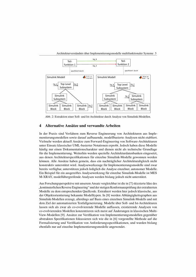
Klassische eingebettete Systeme entwickeln sich zunehmend zu autonomen und offenenSystemen, die auf ihre Umwelt reagieren und im Verbund mit anderen Systemen übergeord-nete Ziele verfolgen. Dabei übernehmen einzelne Systeme immer mehr und vielfältigereAufgaben und werden somit zu multifunktionalen Systemen [1]. Abb. 1 zeigt eine exemplari-sche Übersicht, wie die Entwicklung von multifunktionalen Systemen heute typischerweiseaus Sicht eines Herstellers (engl. Original Equipment Manufacturer (OEM)) strukturiertist. Ein komplexes System wird zunächst zerlegt in Subsysteme, welche die einzelnenFunktionen thematisch gruppieren. Im Fahrzeugbau wird oft von Domänen gesprochen1 Institut für Informatik, Humboldt-Universität zu Berlin. [email protected] Fachgebiet IT-basierte Fahrzeuginnovationen, Technische Universität Berlin. [email protected] Institut für Informatik, Humboldt-Universität zu Berlin. thomas.vogelinformatik.hu-berlin.de4 Model Engineering Solutions GmbH. [email protected]
2 T. Kehrer, A. Vogelsang, T. Vogel, H. Dörr
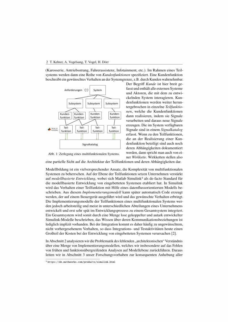
(Karosserie, Antriebsstrang, Fahrerassistenz, Infotainment, etc.). Im Rahmen eines Teil-systems werden dann eine Reihe von Kundenfunktionen spezifiziert. Eine Kundenfunktionbeschreibt ein gewünschtes Verhalten an der Systemgrenze, z.B. durch Kunden wahrnehmbar.
5
SystemAnforderungen
Subsystem Subsystem Subsystem
Teil-funktion
Teil-funktion
Teil-funktion
Teil-funktion
Signalkatalog
Kunden-funktion
Kunden-funktion
Kunden-funktion
Kunden-funktion
Abb. 1: Zerlegung eines multifunktionalen Systems.
Der Begriff Kunde ist hier breit ge-fasst und enthält alle externen Systemeund Aktoren, die mit dem zu entwi-ckelnden System interagieren. Kun-denfunktionen werden weiter herun-tergebrochen in einzelne Teilfunktio-nen, welche die Kundenfunktionendann realisieren, indem sie Signaleverarbeiten und daraus neue Signaleerzeugen. Die im System verfügbarenSignale sind in einem Signalkatalogerfasst. Wenn zu den Teilfunktionen,die an der Realisierung einer Kun-denfunktion beteiligt sind auch nochderen Abhängigkeiten dokumentiertwerden, dann spricht man auch von ei-ner Wirkkette. Wirkketten stellen also
eine partielle Sicht auf die Architektur der Teilfunktionen und deren Abhängigkeiten dar.
Modellbildung ist ein vielversprechender Ansatz, die Komplexität von multifunktionalenSystemen zu beherrschen. Auf der Ebene der Teilfunktionen setzen Unternehmen verstärktauf modellbasierte Entwicklung, wobei sich Matlab Simulink5 als de-facto Standard fürdie modellbasierte Entwicklung von eingebetteten Systemen etabliert hat. In Simulinkwird das Verhalten einer Teilfunktion mit Hilfe eines datenflussorientierten Modells be-schrieben. Aus diesem Implementierungsmodell kann später automatisch Code erzeugtwerden, der auf einem Steuergerät ausgeführt wird und das gewünschte Verhalten erbringt.Die Implementierungsmodelle der Teilfunktionen eines multifunktionalen Systems wer-den jedoch arbeitsteilig und meist in unterschiedlichen Abteilungen eines Unternehmensentwickelt und erst sehr spät im Entwicklungsprozess zu einem Gesamtsystem integriert.Ein Gesamtsystem wird somit durch eine Menge lose gekoppelter und autark entwickelterSimulink-Modelle beschrieben, das Wissen über deren Kommunikationsbeziehungen istlediglich implizit vorhanden. Bei der Integration kommt es daher häufig zu ungewünschtem,nicht vorhergesehenem Verhalten, so dass Integrations- und Testaktivitäten heute einenGroßteil der Kosten bei der Entwicklung von eingebetteten Systemen verursachen [2].
In Abschnitt 2 analysieren wir die Problematik des fehlenden „architektonischen“ Verständnisüber eine Menge von Implementierungsmodellen, welches wir insbesondere auf das Fehlenvon frühen und funktionsübergreifenden Analysen auf Modellebene zurückführen. Darausleiten wir in Abschnitt 3 unser Forschungsvorhaben zur konsequenten Anhebung aller
5 https://de.mathworks.com/products/simulink.html
Architekturverständnis über Implementierungsmodelle multifunktionaler Systeme 3
integrativen Analysetätigkeiten auf die Modellebene ab. Eine Auswahl an alternativenAnsätzen beleuchten wir in Abschnitt 4 und resümieren unser Positionspapier in Abschnitt 5.
2 Problemanalyse
Die Kosten für die Integration und den Test multifunktionaler eingebetteter Systemesind heute trotz modellbasierter Entwicklungsansätze sehr hoch. Kernhypothese unseresForschungsvorhabens ist, dass dies i.W. auf das fehlende architektonische Verständnis übereine Menge lose gekoppelter Implementierungsmodelle zurückzuführen ist.
Eine Integration der Teilfunktionen findet erst auf Code- bzw. Geräteebene und damit sehrspät im Entwicklungsprozess statt, so dass Abhängigkeiten zwischen diesen Teilfunktionenin den früheren Phasen der Entwicklung nicht berücksichtigt werden. Es gibt keine expliziteVerwaltung und Kontrolle über die Abhängigkeiten. In Vorarbeiten haben wir festgestellt,dass vermeintlich unabhängige Kundenfunktionen im Automobilbereich auf der Ebene derTeilfunktionen hochgradig vernetzt sind [3], ca. die Hälfte aller Abhängigkeiten zwischenKundenfunktionen waren den Entwicklern unbekannt. In einem untersuchten Projekt imBereich Automotive Infotainment war das fehlende Verständnis über die Interaktionen derTeilfunktionen die Ursache für mehr als 40% aller Fehler [4]. Ferner werden die Schnittstel-lendefinitionen der Teilfunktionen in vielen Fällen in den Implementierungsmodellen nichteingehalten und es existieren keine Ansätze, um diese Abweichungen kontinuierlich zuprüfen. Feilkas et al. [5] berichten über drei industrielle Fallstudien in denen bis zu 19% allerAbhängigkeiten in der Implementierung von der ursprünglich spezifizierten Architekturabweichen. Dabei war in vielen Fällen den Entwicklern nicht klar, ob es sich bei diesenAbweichungen um Fehler in der Spezifikation oder in der Implementierung handelt. AuchWirkketten werden in der Praxis häufig nur zur Spezifikation von Kundenfunktionen genutzt.Eine Verifikation der implementierten Architektur gegenüber spezifizierten Wirkkettenbleibt häufig aus. Hinzu kommt, dass die Spezifikation mit Hilfe von Wirkketten den Blickfür Abhängigkeiten zwischen Wirkketten trübt. Abhängigkeiten zwischen Teilfunktionenunterschiedlicher Wirkketten sind in der implementierten Architektur vorhanden, spiegelnsich aber nicht in den spezifizierten Wirkketten wieder.
Zusammenfassend lässt sich sagen, dass der Einsatz von Modellbasierung zur frühenFehlervermeidung und Reduzierung von Integrations- und Testkosten zwar vielversprechendist, das volle Potential aber erst ausgeschöpft werden kann, wenn die erstellten Imple-mentierungsmodelle auch modellübergreifend analysiert werden und kontinuierlich aufAbweichungen gegenüber abstrakteren Spezifikationen geprüft werden.
3 Forschungsvorhaben
Übergeordnetes Ziel unseres Forschungsvorhabens ist die Entwicklung von strukturbasiertenVerfahren zur Analyse der Architektur aller kommunizierenden Implementierungsmodelle,
4 T. Kehrer, A. Vogelsang, T. Vogel, H. Dörr
mit denen sich mögliche Integrationsrisiken frühzeitig erkennen lassen. Dies umfasst dieIdentifikation und Erkennung von Architektur-Smells und Anti-Patterns, sowie die Verifikati-on gegenüber funktionsübergreifenden, strukturellen Spezifikationen wie bspw. Wirkketten.Grundlage aller modellbasierten Analysen bildet die tatsächlich vorliegende Architekturüber einer Menge autark entwickelter Implementierungsmodelle, welche in einem erstenReverse Engineering Schritt anhand der impliziten Abhängigkeiten zwischen den kommuni-zierenden Implementierungsmodellen gewonnen werden soll. Die Art und Granularität derextrahierten Architekturmodelle richten sich nach den jeweiligen Analysen. Da Simulink-Modelle oft als Basis für die Codegenerierung dienen, werden diese in der Regel sehr gutgepflegt und aktuell gehalten. Wir planen daher mit unseren Analysen auf einer Menge vonbestehenden Simulink-Modellen aufzusetzen, die jeweils eine Teilfunktion beschreiben. Esist geplant, die Analysen in das Qualitätssicherungswerkzeug MES M-XRAY6 einzubetten.Die entwickelten Verfahren sind jedoch auch auf andere blockorientierte Modelltypen wiebspw. Komponenten- und Konnektormodelle [6] übertragbar.
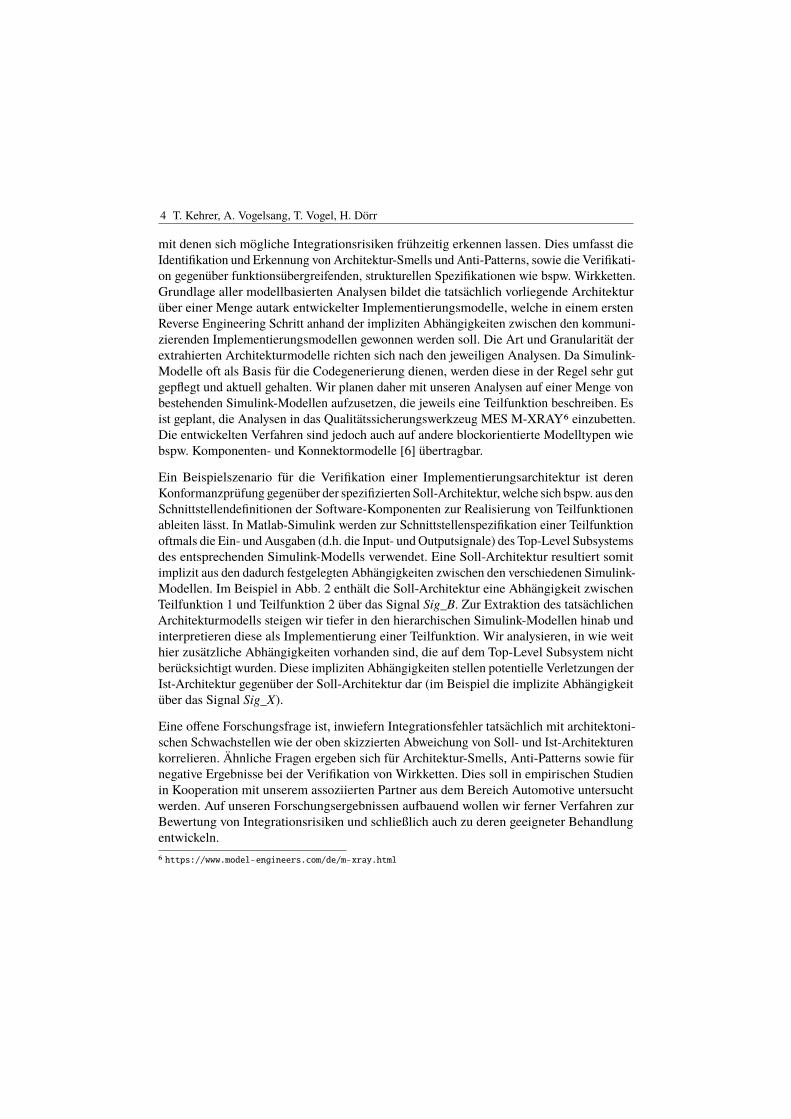
Ein Beispielszenario für die Verifikation einer Implementierungsarchitektur ist derenKonformanzprüfung gegenüber der spezifizierten Soll-Architektur, welche sich bspw. aus denSchnittstellendefinitionen der Software-Komponenten zur Realisierung von Teilfunktionenableiten lässt. In Matlab-Simulink werden zur Schnittstellenspezifikation einer Teilfunktionoftmals die Ein- und Ausgaben (d.h. die Input- und Outputsignale) des Top-Level Subsystemsdes entsprechenden Simulink-Modells verwendet. Eine Soll-Architektur resultiert somitimplizit aus den dadurch festgelegten Abhängigkeiten zwischen den verschiedenen Simulink-Modellen. Im Beispiel in Abb. 2 enthält die Soll-Architektur eine Abhängigkeit zwischenTeilfunktion 1 und Teilfunktion 2 über das Signal Sig_B. Zur Extraktion des tatsächlichenArchitekturmodells steigen wir tiefer in den hierarchischen Simulink-Modellen hinab undinterpretieren diese als Implementierung einer Teilfunktion. Wir analysieren, in wie weithier zusätzliche Abhängigkeiten vorhanden sind, die auf dem Top-Level Subsystem nichtberücksichtigt wurden. Diese impliziten Abhängigkeiten stellen potentielle Verletzungen derIst-Architektur gegenüber der Soll-Architektur dar (im Beispiel die implizite Abhängigkeitüber das Signal Sig_X).
Eine offene Forschungsfrage ist, inwiefern Integrationsfehler tatsächlich mit architektoni-schen Schwachstellen wie der oben skizzierten Abweichung von Soll- und Ist-Architekturenkorrelieren. Ähnliche Fragen ergeben sich für Architektur-Smells, Anti-Patterns sowie fürnegative Ergebnisse bei der Verifikation von Wirkketten. Dies soll in empirischen Studienin Kooperation mit unserem assoziierten Partner aus dem Bereich Automotive untersuchtwerden. Auf unseren Forschungsergebnissen aufbauend wollen wir ferner Verfahren zurBewertung von Integrationsrisiken und schließlich auch zu deren geeigneter Behandlungentwickeln.6 https://www.model-engineers.com/de/m-xray.html
Architekturverständnis über Implementierungsmodelle multifunktionaler Systeme 5
6
Teil-funktion 1
Simulink Modell
Top Level Subsystem
Simulink Block
spezifiziert durch
Simulink Subsystem
Simulink Block
Simulink Block
Teil-funktion 2
Simulink Modell
Top Level Subsystem
Simulink Block
spezifiziert durch
Simulink Subsystem
Simulink Block
Simulink Block
Simulink Subsystem
Simulink Block
Sig_A Sig_B Sig_B Sig_C
Sig_X
Sig_X
Sig_B
Sig_X
Abb. 2: Extraktion einer Soll- und Ist-Architektur durch Analyse von Simulink-Modellen.
4 Alternative Ansätze und verwandte Arbeiten
In der Praxis sind Verfahren zum Reverse Engineerung von Architekturen aus Imple-mentierungsmodellen sowie darauf aufbauende, modellbasierte Analysen nicht etabliert.Vielmehr werden aktuell Ansätze zum Forward-Engineering von Software-Architekturenunter Einsatz klassischer UML-basierter Notationen erprobt. Jedoch haben diese Modellehäufig nur einen Dokumentationscharakter und dienen nicht als technische Grundlagefür die Implementierung. Weiterhin werden spezielle Architekturdatenbanken eingesetzt,aus denen Architekturspezifikationen für einzelne Simulink-Modelle gewonnen werdenkönnen. Alle Ansätze haben gemein, dass ein nachträglicher Architekturabgleich nichtkonstruktiv unterstützt wird. Analysewerkzeuge für Implementierungsmodelle sind zwarbereits verfügbar, unterstützen jedoch lediglich die Analyse einzelner, autonomer Modelle.Ein Beispiel für ein ausgereiftes Analysewerkzeug für einzelne Simulink-Modelle ist MESM-XRAY, modellübergreifende Analysen werden bislang jedoch nicht unterstützt.
Aus Forschungsperspektive mit unserem Ansatz vergleichbar ist die in [7] skizzierte Idee des„kontinuierlichen Reverse Engineering“ und der stetigen Konformanzprüfung der extrahiertenModelle zu dem entsprechenden Quellcode. Extrahiert werden hier jedoch klassische, ausder Objektorientierung bekannte Modelltypen. In [8] werden Abhängigkeitsgraphen ausSimulink-Modellen erzeugt, allerdings auf Basis eines einzelnen Simulink-Modells und mitdem Ziel der automatisierten Testfallgenerierung. Modelle über Soll- und Ist-Architekturenlassen sich als zwar als co-evolvierende Modelle auffassen, existierende Analysen vonco-evolvierenden Modellen konzentrieren sich meist auf Änderungen in klassischen Multi-View-Modellen [9]. Ansätze zur Verifikation von Implementierungsmodellen gegenüberabstrakten Spezifikationen fokussieren sich wie die in [6] vorgestellte Methode auf dieFormalisierung und Verifikation von Anforderungsspezifikationen, und wurden bislangebenfalls nur auf einzelne Implementierungsmodelle angewendet.
6 T. Kehrer, A. Vogelsang, T. Vogel, H. Dörr
5 Resümee
Trotz modellbasierter Methoden ist die Entwicklung multifunktionaler eingebetteter Sys-teme eine überaus aktuelle Herausforderung. Ein Gesamtsystem wird in der Praxis meistdurch eine Menge lose gekoppelter Simulink-Modelle beschrieben, ein architektonischesVerständnis über deren Kommunikationsbeziehungen ist lediglich implizit vorhanden, waszu hohen Integrationskosten führt. Ziel unseres Forschungsvorhabens ist die Entwicklungvon strukturbasierten Verfahren zur Analyse der Architektur aller kommunizierenden Im-plementierungsmodelle, mit denen sich mögliche Integrationsrisiken frühzeitig erkennen,bewerten und letzten Endes auch behandeln lassen.
Literatur
[1] Manfred Broy. „Multifunctional software systems: Structured modeling and speci-fication of functional requirements“. In: Science of Computer Programming 75.12(2010).
[2] Claudiu Farcas u. a. „Addressing the Integration Challenge for Avionics and AutomotiveSystems—From Components to Rich Services“. In: Proc. of the IEEE 98.4 (2010),S. 562–583.
[3] Andreas Vogelsang und Steffen Fuhrmann. „Why Feature Dependencies Challengethe Requirements Engineering of Automotive Systems: An Empirical Study“. In: Proc.IEEE International Requirements Engineering Conference (RE’13). 2013.
[4] Sebastian Benz. „Generating Tests for Feature Interaction“. Diss. Technische Universi-tät München, 2010.
[5] Martin Feilkas, Daniel Ratiu und Elmar Jurgens. „The loss of architectural knowledgeduring system evolution: An industrial case study“. In: International Conference onProgram Comprehension (ICPC). IEEE. 2009, S. 188–197.
[6] Vincent Bertram u. a. „Component and Connector Views in Practice: An Experi-ence Report“. In: 2017 ACM/IEEE 20th International Conference on Model DrivenEngineering Languages and Systems (MODELS). IEEE. 2017, S. 167–177.
[7] Gerardo Canfora, Massimiliano Di Penta und Luigi Cerulo. „Achievements andChallenges in Software Reverse Engineering“. In: Commun. ACM 54.4 (2011).
[8] Adepu Sridhar, D. Srinivasulu und Durga P. Mohapatra. „Model-based test-casegeneration for Simulink/Stateflow using dependency graph approach“. In: IEEEInternational Advance Computing Conference (IACC). 2013.
[9] Sinem Getir, Michaela Rindt und Timo Kehrer. „A Generic Framework for AnalyzingModel Co-Evolution.“ In: ME @ MoDELS. 2014.
Qualification of Model-Based Development Tools A Case Study
Mirko Conrad1 samoconsult GmbH
mirko.conrad @ samoconsult.de
Sophia Kohle, Hartmut Pohlheim Model Engineering Solutions GmbH [email protected]
Abstract: Modern functional safety standards typically provide objectives or re-quirements on how to gain confidence in development tools used for electric and/or electronic systems. The corresponding approaches are referred to as tool qualification, tool validation, or tool certification. To gain confidence in the tools used to develop automotive E/E systems, the ISO 26262 standard outlines a two-step approach consisting of tool classification poten-tially followed by tool qualification. Although some research about ISO 26262 tool classification has been published, in-formation about the tool qualification part is rather limited. This paper intends to re-duce this gap by reporting on the qualification of MXAM, a static analysis tool for Simulink/TargetLink models.
1 Introduction
Software tools are widely used in multiple domains to assist in developing or verifying electric and/or electronic systems (E/E systems). In E/E system development, such tools can assist with analysis and potentially improve system safety by automating the activities performed and by predictably performing tasks that may be prone to human error. On the contrary, an error in a tool may have a negative impact on safety if the tool inadequately performs its intended functions (cf. [DO 330]).
To reduce the potential risks associated with tool usage and to ensure the integrity of the tool functionality, recent (functional) safety standards call for dedicated activities to gain confidence in the tools used in the development of E/E systems. Depending on the domain or standard, the corresponding approaches are referred to as tool validation, tool qualifi-cation, or tool certification.
For the development of automotive E/E systems, the pertinent functional safety standard is ISO 26262 [ISO 26262]. Part 8 of this standard calls for a two-step process to gain
1 https://orcid.org/0000-0003-3221-6503
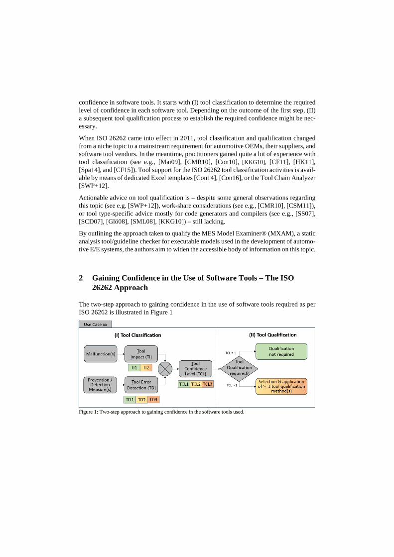
confidence in software tools. It starts with (I) tool classification to determine the required level of confidence in each software tool. Depending on the outcome of the first step, (II) a subsequent tool qualification process to establish the required confidence might be nec-essary.
When ISO 26262 came into effect in 2011, tool classification and qualification changed from a niche topic to a mainstream requirement for automotive OEMs, their suppliers, and software tool vendors. In the meantime, practitioners gained quite a bit of experience with tool classification (see e.g., [Mai09], [CMR10], [Con10], [KKG10], [CF11], [HK11], [Spä14], and [CF15]). Tool support for the ISO 26262 tool classification activities is avail-able by means of dedicated Excel templates [Con14], [Con16], or the Tool Chain Analyzer [SWP+12].
Actionable advice on tool qualification is – despite some general observations regarding this topic (see e.g. [SWP+12]), work-share considerations (see e.g., [CMR10], [CSM11]), or tool type-specific advice mostly for code generators and compilers (see e.g., [SS07], [SCD07], [Glö08], [SML08], [KKG10]) – still lacking.
By outlining the approach taken to qualify the MES Model Examiner® (MXAM), a static analysis tool/guideline checker for executable models used in the development of automo-tive E/E systems, the authors aim to widen the accessible body of information on this topic.
2 Gaining Confidence in the Use of Software Tools – The ISO 26262 Approach
The two-step approach to gaining confidence in the use of software tools required as per ISO 26262 is illustrated in Figure 1
Figure 1: Two-step approach to gaining confidence in the software tools used.
2.1 Tool Classification
Tool classification is based on the actual/intended usage of the tool. Therefore, the tool usage needs to be documented by means of tool use cases. Each of the use cases is sub-jected to further analysis.
First, potential malfunctions of the tool that could occur in the context of the use case at hand need to be identified and documented. For each malfunction, it needs to be deter-mined whether the tool could introduce errors into the E/E system under development or fail to detect such errors. If it can be argued that there is no such possibility, the malfunc-tion has a tool impact of 1 (TI1), otherwise the tool impact is 2 (TI2). If all malfunctions in the context of a given use case are rated TI1, the entire use case can be considered TI1.
Second, the measures applied to prevent or detect these malfunctions or their resulting erroneous output need to be documented and the confidence in these measures needs to be rated. Depending on whether there is high, medium, or even low confidence, the tool error detection is 1 (TD1), 2 (TD2), or 3 (TD3) respectively. In addition to the error detection of the individual measures, the tool error detection of a combination of measures might be rated [Con16] 2.
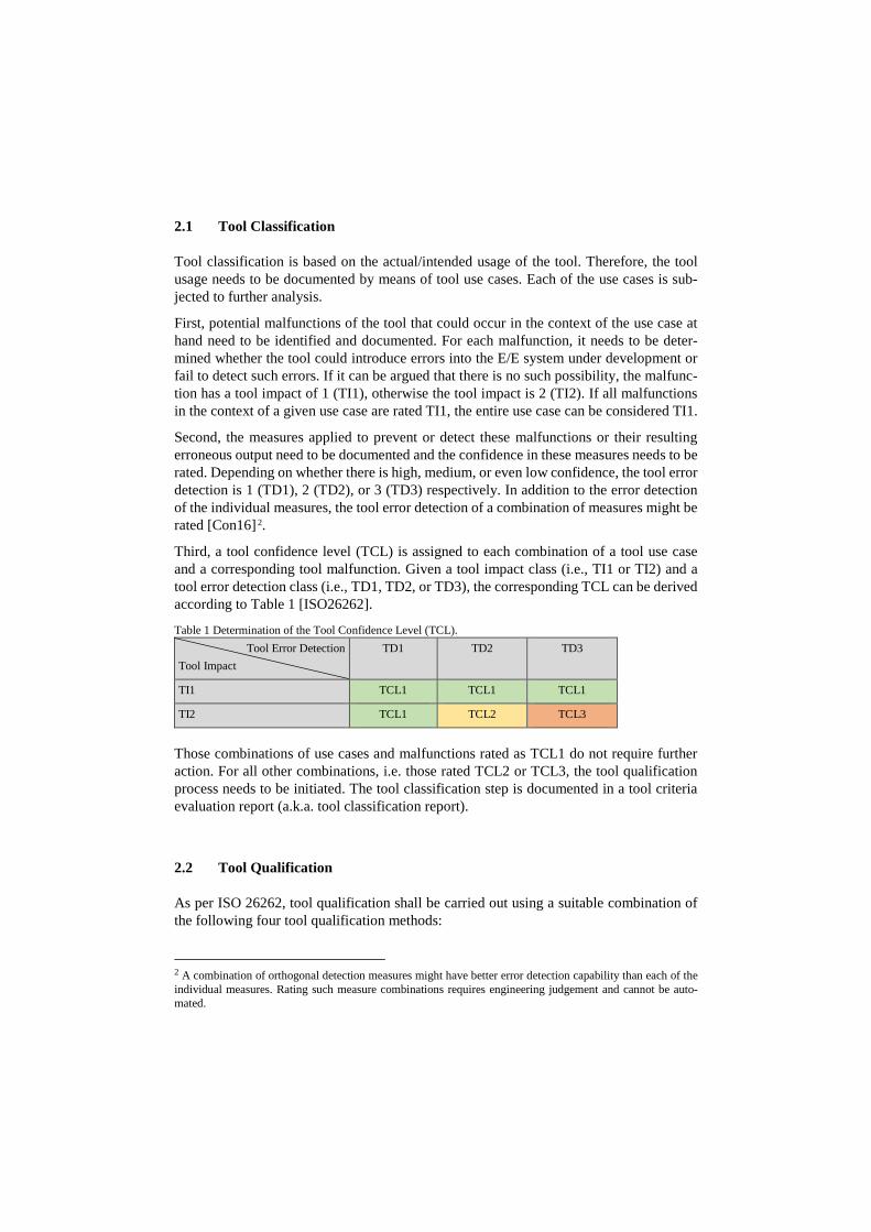
Third, a tool confidence level (TCL) is assigned to each combination of a tool use case and a corresponding tool malfunction. Given a tool impact class (i.e., TI1 or TI2) and a tool error detection class (i.e., TD1, TD2, or TD3), the corresponding TCL can be derived according to Table 1 [ISO26262].
Table 1 Determination of the Tool Confidence Level (TCL). Tool Error Detection
Tool Impact TD1 TD2 TD3
TI1 TCL1 TCL1 TCL1
TI2 TCL1 TCL2 TCL3
Those combinations of use cases and malfunctions rated as TCL1 do not require further action. For all other combinations, i.e. those rated TCL2 or TCL3, the tool qualification process needs to be initiated. The tool classification step is documented in a tool criteria evaluation report (a.k.a. tool classification report).
2.2 Tool Qualification
As per ISO 26262, tool qualification shall be carried out using a suitable combination of the following four tool qualification methods:
2 A combination of orthogonal detection measures might have better error detection capability than each of the individual measures. Rating such measure combinations requires engineering judgement and cannot be auto-mated.

a) Increased confidence from use. b) Evaluation of the tool development process. c) Validation of the software tool. d) Development in compliance with a safety standard.
The selection of appropriate tool qualification methods depends on the TCL and on the Automotive Safety Integrity Level (ASIL) of the E/E system to be developed.
However, the practical significance of tool qualification methods a) 3 and d) is rather lim-ited 4. The vast majority of all tool qualification approaches known to the authors use method b) or c) or a combination thereof.
If the method b) ‘Evaluation of the tool development process’ is applied to qualify a soft-ware tool, its tool development process shall comply with an appropriate standard. The tool development process shall be assessed based on an appropriate national or interna-tional standard (e.g., Automotive SPICE, CMMI, or ISO 15504) and the proper applica-tion of the assessed development process shall be demonstrated.
If the method c) ‘Validation of the software tool’ is utilized, the validation of the software tool shall meet three criteria:
a) It shall be demonstrated that the software tool complies with its specified require-ments, e.g., by using validation tests or reviews designed to evaluate functional and non-functional quality aspects of the tool.
b) If malfunctions occur during the validation, these malfunctions and the resulting erroneous outputs shall be analyzed. Also, information on their possible conse-quences and measures to avoid or detect them shall be provided.
c) The reaction of the software tool to anomalous operating conditions (e.g., fore-seeable misuse, incomplete input data, and incompatible combinations of config-uration settings) shall be examined.
The tool qualification step is documented in a tool qualification report.
3 Case Study: MXAM Qualification Kit
When utilizing the model-based development paradigm to develop automotive E/E sys-tems, software units can be designed by means of executable Simulink or TargetLink mod-els. Prior to code generation, the unit design needs to be statically analyzed to verify compliance with the applicable modeling guidelines. Modeling guideline checking can be carried out using MXAM.
3 Although a) sounds promising, it is rarely applicable due to frequent changes/updates to the tools being used. 4 Given the number and variety of development tools for E/E systems, proof of formal correctness could replace or extend the listed qualification methods for only a small subset of these tools.
3.1 The MES Model Examiner® DRIVE
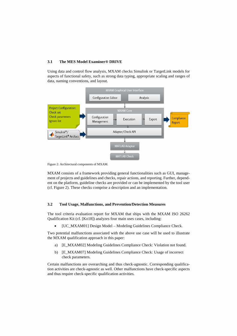
Using data and control flow analysis, MXAM checks Simulink or TargetLink models for aspects of functional safety, such as strong data typing, appropriate scaling and ranges of data, naming conventions, and layout.
Figure 2: Architectural components of MXAM. MXAM consists of a framework providing general functionalities such as GUI, manage-ment of projects and guidelines and checks, repair actions, and reporting. Further, depend-ent on the platform, guideline checks are provided or can be implemented by the tool user (cf. Figure 2). These checks comprise a description and an implementation.
3.2 Tool Usage, Malfunctions, and Prevention/Detection Measures
The tool criteria evaluation report for MXAM that ships with the MXAM ISO 26262 Qualification Kit (cf. [Ko18]) analyzes four main uses cases, including:
• [UC_MXAM01] Design Model – Modeling Guidelines Compliance Check.
Two potential malfunctions associated with the above use case will be used to illustrate the MXAM qualification approach in this paper:
a) [E_MXAM02] Modeling Guidelines Compliance Check: Violation not found.
b) [E_MXAM07] Modeling Guidelines Compliance Check: Usage of incorrect check parameters.
Certain malfunctions are overarching and thus check-agnostic. Corresponding qualifica-tion activities are check-agnostic as well. Other malfunctions have check-specific aspects and thus require check-specific qualification activities.
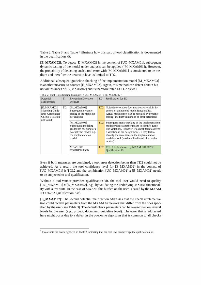
Table 2, Table 3, and Table 4 illustrate how this part of tool classification is documented in the qualification kit.
[E_MXAM02]: To detect [E_MXAM02] in the context of [UC_MXAM01], subsequent dynamic testing of the model under analysis can be applied ([M_MXAM01]). However, the probability of detecting such a tool error with [M_MXAM01] is considered to be me-dium and therefore the detection level is limited to TD2.
Additional subsequent guideline checking of the implementation model [M_MXAM03] is another measure to counter [E_MXAM02]. Again, this method can detect certain but not all instances of [E_MXAM02] and is therefore rated as TD2 as well.
Table 2: Tool Classification Example I ([UC_MXAM01] x [E_MXAM02]) Potential Malfunction
TI Prevention/Detection Measure
TD Justification for TD
[E_MXAM02] Modeling Guide-lines Compliance Check: Violation not found
TI2 [M_MXAM01] Subsequent dynamic testing of the model un-der analysis
TD2 Guideline violation does not always result in in-correct or unintended model functionality. Actual model errors can be revealed by dynamic testing ('medium' likelihood of error detection).
[M_MXAM03] Subsequent modeling guidelines checking of a downstream model, e.g. the implementation model
TD2 Subsequent static checking of the implementation model provides another means to identify guide-line violations. However, if a check fails to detect a violation in the design model, it may fail to identify the same issue in the implementation model as well ('medium' likelihood of error de-tection).
MEASURE COMBINATION
TD2 TCL 2 Addressed by MXAM ISO 26262 Qualification Kit.
Even if both measures are combined, a tool error detection better than TD2 could not be achieved. As a result, the tool confidence level for [E_MXAM02] in the context of [UC_MXAM01] is TCL2 and the combination [UC_MXAM01] x [E_MXAM02] needs to be subjected to tool qualification.
Without a tool-vendor-provided qualification kit, the tool user would need to qualify [UC_MXAM01] x [E_MXAM02], e.g., by validating the underlying MXAM functional-ity with a test suite. In the case of MXAM, this burden on the user is eased by the MXAM ISO 26262 Qualification Kit 5.
[E_MXAM07]: The second potential malfunction addresses that the check implementa-tion could receive parameters from the MXAM framework that differ from the ones spec-ified by the user (see Table 3). The default check parameters can be overwritten on several levels by the user (e.g., project, document, guideline level). The error that is addressed here might occur due to a defect in the overwrite algorithm that is common to all checks
5 Please note the lower right cell in Table 2 indicating that the tool user can leverage the qualification kit.
(i.e. check-agnostic). Malfunctions in the check-specific handling of check parameters are covered by [E_MXAM02].
Table 3: Tool Classification Example II ([UC_MXAM01] x [E_MXAM07] – Initial Classification) Potential Malfunction TI Error Prevention/
Detection Measure TD Justification for TD
[E_MXAM07] Modeling Guidelines Com-pliance Check: Usage of in-correct check parameters
TI2 [M_MXAM13] Review of parameter specification details
TD1 Review of the parameter specifi-cation details ensures the correct-ness of the guideline check parameters to be used.
[M_MXAM11] Check for Error Mes-sages
TD2 Checking logs and compliance re-ports for error messages helps to detect anomalies such as an incor-rect parameter definition.
MEASURE COMBINATION
TD1 TCL 1
Malfunction [E_MXAM07] could be mitigated by reviewing the parameter specification details provided by MXAM ([M_MXAM13]) as these document the actual check param-eters used during check execution. Thus, sufficient error prevention is possible (TCL1, cf. Table 3), but the necessary review activities would be very time consuming as they need to be performed for each individual overwritten parameter.
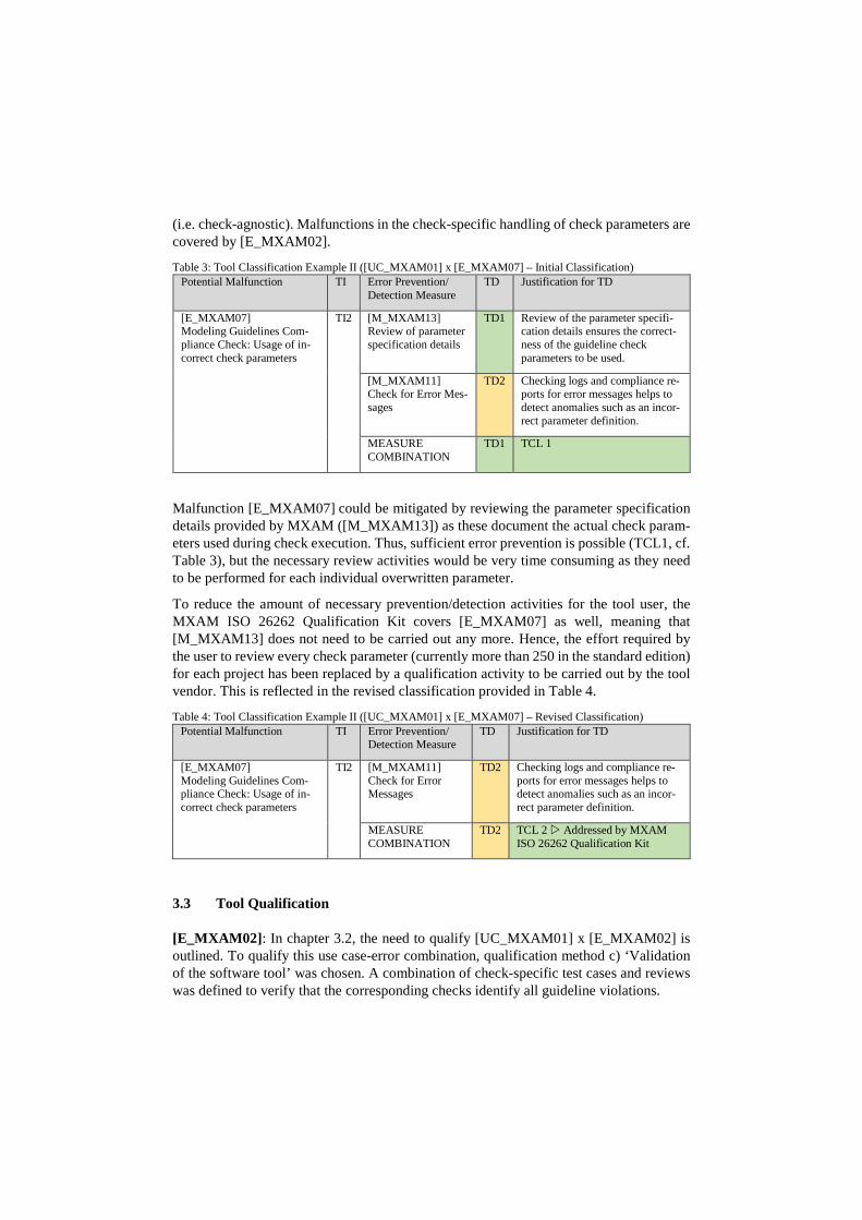
To reduce the amount of necessary prevention/detection activities for the tool user, the MXAM ISO 26262 Qualification Kit covers [E_MXAM07] as well, meaning that [M_MXAM13] does not need to be carried out any more. Hence, the effort required by the user to review every check parameter (currently more than 250 in the standard edition) for each project has been replaced by a qualification activity to be carried out by the tool vendor. This is reflected in the revised classification provided in Table 4.
Table 4: Tool Classification Example II ([UC_MXAM01] x [E_MXAM07] – Revised Classification) Potential Malfunction TI Error Prevention/
Detection Measure TD Justification for TD
[E_MXAM07] Modeling Guidelines Com-pliance Check: Usage of in-correct check parameters
TI2 [M_MXAM11] Check for Error Messages
TD2 Checking logs and compliance re-ports for error messages helps to detect anomalies such as an incor-rect parameter definition.
MEASURE COMBINATION
TD2 TCL 2 Addressed by MXAM ISO 26262 Qualification Kit
3.3 Tool Qualification
[E_MXAM02]: In chapter 3.2, the need to qualify [UC_MXAM01] x [E_MXAM02] is outlined. To qualify this use case-error combination, qualification method c) ‘Validation of the software tool’ was chosen. A combination of check-specific test cases and reviews was defined to verify that the corresponding checks identify all guideline violations.
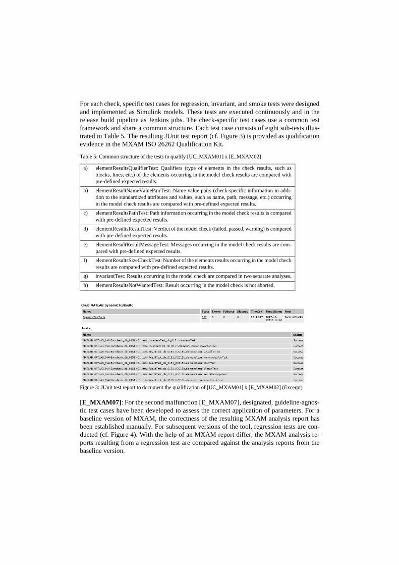
For each check, specific test cases for regression, invariant, and smoke tests were designed and implemented as Simulink models. These tests are executed continuously and in the release build pipeline as Jenkins jobs. The check-specific test cases use a common test framework and share a common structure. Each test case consists of eight sub-tests illus-trated in Table 5. The resulting JUnit test report (cf. Figure 3) is provided as qualification evidence in the MXAM ISO 26262 Qualification Kit.
Table 5: Common structure of the tests to qualify [UC_MXAM01] x [E_MXAM02]
a) elementResultsQualifierTest: Qualifiers (type of elements in the check results, such as blocks, lines, etc.) of the elements occurring in the model check results are compared with pre-defined expected results.
b) elementResultNameValuePairTest: Name value pairs (check-specific information in addi-tion to the standardized attributes and values, such as name, path, message, etc.) occurring in the model check results are compared with pre-defined expected results.
c) elementResultsPathTest: Path information occurring in the model check results is compared with pre-defined expected results.
d) elementResultsResultTest: Verdict of the model check (failed, passed, warning) is compared with pre-defined expected results.
e) elementResultResultMessageTest: Messages occurring in the model check results are com-pared with pre-defined expected results.
f) elementResultsSizeCheckTest: Number of the elements results occurring in the model check results are compared with pre-defined expected results.
g) invariantTest: Results occurring in the model check are compared in two separate analyses.
h) elementResultsNotWantedTest: Result occurring in the model check is not aborted.
Figure 3: JUnit test report to document the qualification of [UC_MXAM01] x [E_MXAM02] (Excerpt) [E_MXAM07]: For the second malfunction [E_MXAM07], designated, guideline-agnos-tic test cases have been developed to assess the correct application of parameters. For a baseline version of MXAM, the correctness of the resulting MXAM analysis report has been established manually. For subsequent versions of the tool, regression tests are con-ducted (cf. Figure 4). With the help of an MXAM report differ, the MXAM analysis re-ports resulting from a regression test are compared against the analysis reports from the baseline version.
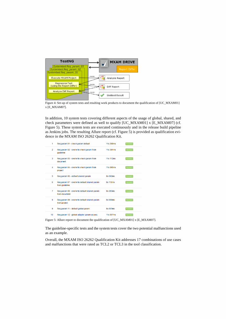
Figure 4: Set-up of system tests and resulting work products to document the qualification of [UC_MXAM01] x [E_MXAM07].
In addition, 10 system tests covering different aspects of the usage of global, shared, and check parameters were defined as well to qualify [UC_MXAM01] x [E_MXAM07] (cf. Figure 5). These system tests are executed continuously and in the release build pipeline as Jenkins jobs. The resulting Allure report (cf. Figure 5) is provided as qualification evi-dence in the MXAM ISO 26262 Qualification Kit.
Figure 5: Allure report to document the qualification of [UC_MXAM01] x [E_MXAM07]. The guideline-specific tests and the system tests cover the two potential malfunctions used as an example.
Overall, the MXAM ISO 26262 Qualification Kit addresses 17 combinations of use cases and malfunctions that were rated as TCL2 or TCL3 in the tool classification.
3.4 User Activities and Savings
Using a tool-vendor-provided qualification kit can significantly streamline the user’s tool classification and qualification activities. However, it does not exempt the tool user from having to perform any further activities.
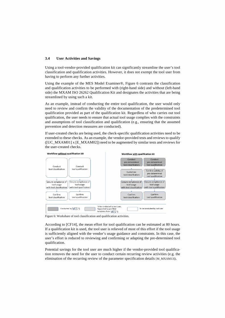
Using the example of the MES Model Examiner®, Figure 6 contrasts the classification and qualification activities to be performed with (right-hand side) and without (left-hand side) the MXAM ISO 26262 Qualification Kit and designates the activities that are being streamlined by using such a kit.
As an example, instead of conducting the entire tool qualification, the user would only need to review and confirm the validity of the documentation of the predetermined tool qualification provided as part of the qualification kit. Regardless of who carries out tool qualification, the user needs to ensure that actual tool usage complies with the constraints and assumptions of tool classification and qualification (e.g., ensuring that the assumed prevention and detection measures are conducted).
If user-created checks are being used, the check-specific qualification activities need to be extended to these checks. As an example, the vendor-provided tests and reviews to qualify ([UC_MXAM01] x [E_MXAM02]) need to be augmented by similar tests and reviews for the user-created checks.
Figure 6: Workshare of tool classification and qualification activities. According to [CF14], the mean effort for tool qualification can be estimated at 80 hours. If a qualification kit is used, the tool user is relieved of most of this effort if the tool usage is sufficiently aligned with the vendor’s usage guidance and constraints. In this case, the user’s effort is reduced to reviewing and confirming or adapting the pre-determined tool qualification.
Potential savings for the tool user are much higher if the vendor-provided tool qualifica-tion removes the need for the user to conduct certain recurring review activities (e.g. the elimination of the recurring review of the parameter specification details [M_MXAM13]).
The MXAM ISO 26262 Qualification Kit provides the user with designated and flexible Word and Excel templates for the required ISO 26262 classification and qualification work products. User feedback indicates, that such templates are preferred to other availa-ble solutions as they are easy to comprehend and adaptation to established, user-specific workflows is straightforward.
4 Summary and Conclusion
Gaining confidence in the tools used to develop E/E systems via tool classification and tool qualification is a base requirement for today’s development projects. Modern func-tional safety standards, such as ISO 26262, call for these activities. The responsibility for conducting these activities rests with the tool user. However, support from the tool vendor can streamline the user activities.
Vendor-provided tool classification already reduces the effort for the user when evaluating the confidence in the tool for the intended use cases. Instead of creating the entire classi-fication, the user only needs to review and confirm or adapt the predetermined tool clas-sification.
However, if the tool classification results in a TCL2 or TCL3 (medium or low tool confi-dence) for some use cases, users need to apply additional prevention/detection measures or must qualify the tool with respect to these use cases. For some use cases, sufficient tool confidence (i.e., TCL1) can be reached by conducting additional review activities. For other use cases, such additional activities might be infeasible or prohibitive due to high complexity or effort. Tool qualification is the only option here.
Using the example of the MES Model Examiner®, this paper provides insight into the structure and the qualification approach of an actual tool qualification kit for a popular model-based analysis tool. The tool qualification kit utilizes the qualification method ‘val-idation of the software tool’; validation is conducted by a combination of different tests and reviews. Utilizing such a tool-vendor-provided qualification kit significantly reduces the burden on the tool user by minimizing the actual qualification effort and also by re-ducing the amount of prevention/detection measures they need to carry out.
Further research interests of the authors include a taxonomy of tool classification ap-proaches, the provision of tool classification patterns, and further improvement of the uti-lized classification and qualification templates.
References
[CF11] M. Conrad, I. Fey “ISO 26262 - Exemplary tool classification of Model-Based Design tools”. Softwaretechnik-Trends 31 (2011) 3 http://pi.informatik.uni-siegen.de/stt/31_3/01_Fachgruppenberichte/ada/5-CF11-11_20110803.pdf

[CF14] M. Conrad, I. Fey “Effort and Efficacy of Tool Classification and Qualification”. Proc. MBEES X (2014)
[CF15] M. Conrad, I. Fey “Tool Classification & Qualification According to ISO 26262”. 4th Int. CTI Conf. ISO 26262 (2015)
[CMR10] M. Conrad, P. Munier, F. Rauch “Qualifying Software Tools According to ISO 26262”. Proc. MBEES VI (2010)
[Con10] M. Conrad “Software Tool Qualification According to ISO 26262 - An Experience Re-port”. Supplementary Proc. of 21. Int. Symposium on Software Reliability Engineering (ISSRE 2010), pp. 460-466 (2010)
[Con14] M. Conrad “Tool Classification and Qualification in Practice” 4th VDA Automotive SYS Conference (2014)
[Con16] M. Conrad, I. Fey “Tool Classification Made Easy - The Making of an ISO 26262 Tool Classification Kit”. MES User Forum 2016 (2016)
[CSM11] M. Conrad, G. Sandmann, P. Munier “Software Tool Qualification According to ISO 26262”. SAE 2011 World Congress, Detroit, MI, US, April 2011 (2011) doi:10.4271/2011-01-1005
[DO330] DO-330:2011. “Software Tool Qualification Considerations”. RTCA (2011) [Glö08] T. Glötzner “IEC 61508 Certification of a Code Generator”. ICSS2008 (2008) [HK+11] R. Hamann, S. Kriso, K. Williams, J. Klarmann, J. Sauler “ISO 26262 Release Just
Ahead: Remaining problems and Proposals for Solutions”. SAE 2011 World Congress, Detroit, MI, US, April 2011 (2011)
[ISO26262] ISO 26262:2011. “Road vehicles - Functional safety”. Int. Org. for Standardization (2011-2012)
[KKG10] J. Klarmann, S. Kriso, M. Gebhardt “Qualification of development tools as per ISO 26262”. REAL TIMES, 1/2010, pp. 28-20 (2010)
[Ko18] S. Kohle “MES Model Examiner® Drive ISO 26262 Qualification Kit”. Model Engi-neering Solutions GmbH, https://www.model-engineers.com/mxam.html (2018)
[Mai09] M. Maihöfer "Umgang mit Entwicklungswerkzeugen in Software-Entwicklungsprozes-sen der Automobilindustrie - ISO DIS 26262, Band 8, Kapitel 11: Inhalt, Bewertung, Auswirkung und Umsetzung (in German). EUROFORUM Konferenz 'Funktionale Si-cherheit nach ISO/DIS 26262', Stuttgart, Germany, Sept. 2009 (2009)
[SCD+07] I. Stürmer, M. Conrad, H. Dörr, P. Pepper “Systematic Testing of Model-Based Code Generators”. IEEE Transactions on Software Engineering, 33 (2007) 9 doi:10.1109/TSE.2007.70708
[SML08] S. Schneider, P. Mai, T. Lovric “The Validation Suite Approach to Safety Qualification of Tools” Automotive - Safety & Security 2008 (2008)
[Spä14] A. Späthe “Den Nagel auf den Kopf zu treffen, reicht nicht - Carmeq führt die ISO-26262-konforme Klassifizierung von Software-Werkzeugen ein“. meilenstein 2/2013, pp. 14-15 (2013) http://www.carmeq.com/downloads/Meilenstein-2-2013.pdf
[SS07] S. Schneider, O. Slotosch “A validation suite for Model-based Development Tools” 10. Int. Conf. on Quality Engineering in Software Technology CONQUEST (2007)
[SWP+12] O. Slotosch, M. Wildmoser, J. Philipps, R. Jeschull, R. Zalman “ISO 26262 - Tool Chain Analysis Reduces Tool Qualification Costs”. Automotive - Safety & Security 2012 (2012)
cbe
(Hrsg.): Modellbasierte Entwicklung eingebetteter Systeme,Lecture Notes in Informatics (LNI), Gesellschaft für Informatik, Bonn 2017 1
Feature-based Recommendation for Product Configurationin the Software Product Lines
Yibo Wang1, Lothar Hotz2, Matthias Riebisch3
Abstract: Software Product Line Engineering (SPLE) is a mature technique enabling companies tocreate individual products in order to meet needs of different customers. In SPLE, Feature Modelsare the widely used formalism to capture commonality and variability of all products. In FeatureModels, program functionalities or other user-visible aspects are represented as Features. In order toconfigure a product, product line users (such as product managers) select desired features step by stepin the Feature Model. However, it is a challenging task in industrial settings, due to high numbers offeatures and complex interdependency between features. Configuration support is required.
In this paper, we propose a similarity-based recommender system that provides online recommen-dation during the user’s configuration process. Online means that the recommendation result isbased on the current feature selections (partial configuration) by the user. In addition, configurationsof all previous products are considered as further input data for the recommender system. Unlikeother similarity-based recommender systems, we use "Feature Implication" (it implies coexistence offeatures in the previous configurations) to measure relations between features. A real case study showsthat our approach outperforms other state-of-the-art similarity-based approaches in recommendationquality. In other words, it help users not only in finding the correct configuration, but also in makingdecisions more efficient.
Keywords: Product Configuration; Recommender Systems; Software Product Lines
1 IntroductionNowadays, mass customization helps companies to meet customer requirements at massproduction efficiencies. Software Product Lines Engineering (SPLE) is a mature techniqueto realize it. SPLE makes it possible to create an individual product by assembling a setof reusable assets. In the domain of SPLE, the Feature Model [Cz12] is one of the mostused formalisms, which captures commonality and variability among all products in termsof Features. A Feature [Ka90] is defined as a "prominent or distinctive user-visible aspect,quality, or characteristic of a software system or system". Configuration is one of the mostimportant activities to build an individual product from the product line. In the configurationprocess, some features will be selected by product line users (followings as users), in orderto meet the individual requirements for a customer. But the configuration is more thanfeature selections. It includes also other activities, such as setting of the feature parameters.
1 University Hamburg, SWK, Vogt-Kölln-Str.30, 22527 Hamburg, Germany, [email protected] HITeC, Vogt-Kölln-Str.30, 22527 Hamburg, Germany, [email protected] University Hamburg, SWK, Vogt-Kölln-Str.30, 22527 Hamburg, [email protected]
2 Yibo Wang, Lothar Hotz, Matthias Riebisch
However, there exist approaches that change feature parameters into a group of exclusivefeatures [KO14]. So we simplify the configuration as feature selections in this paper.
In industrial settings, a configuration is normally a complex task, because of high number offeatures and complex feature inter-dependencies. Moreover, the configuration is a gradualand iterative process. In each step some features will be selected (partial configuration).Users often don’t have an overview of the whole configuration, due to lack of knowledgeabout impacts of their feature selections. Thus, automatic support is required to give userssome guidances on the current feature selections. They exist in two forms: consistencychecking and feature recommendation. Consistency checking is a hard form of configurationsupport. It ensures the validity of the current feature selections. It means that the featureselections that lead to inconsistency are not permitted. On the contrary, recommendation isa soft form. It provides only suggestions (e.g. "you should consider the feature ’X’, becauseit exists in most of the previous configurations"). But these suggestions can be ignored. Inthis paper, we concentrate on the recommendation part and show how to integrate it withthe existing consistency checking approaches (such as SAT solvers).
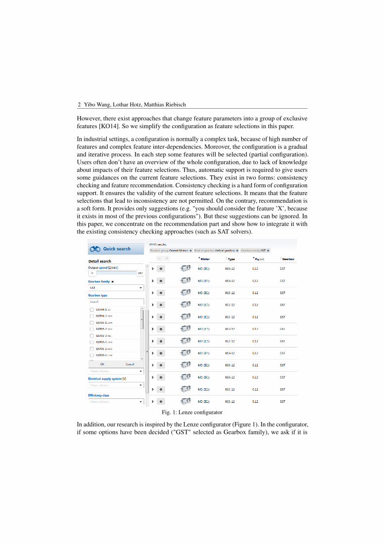
Fig. 1: Lenze configurator
In addition, our research is inspired by the Lenze configurator (Figure 1). In the configurator,if some options have been decided ("GST" selected as Gearbox family), we ask if it is
Feature-based Recommendation 3
possible to provide suggestions for other options (recommend "GST06-2" as Gear type), inconsideration of the set of all available product variants?
[Pe16] follows the similar ideas to provide recommendations. The authors suggest to use thestandard recommenders, such as similarity-based Collaborative Filtering (in the followingreferred to as CF) and Bias Regularized Incremental Simultaneous Matrix Factorization (inthe following referred to as BRISMF), because they provide better recommendation resultsthan other state-of-the-art ones. Our approach goes a step further by adapting the standardrecommendation algorithm CF to the specific problem, namely to the feature selectionproblem.
The contributions are summarized as follows. First we propose a similarity-based featurerecommender system, by using "Feature Implication" derived from previous configurationsto generate recommendations. Second, we design a tool support by extending a state-of-the-art recommender system. Last but not least, we evaluate the tool (in precision/recalland run time) with a real-world data set. The results show that it provides more preciserecommendation results than the traditional similarity-based approaches.
2 Background2.1 Product-Line Engineering
SPLE defines two main processes, namely the Domain Engineering and the ApplicationEngineering. The Domain Engineering consists of the activities such as domain analysis,setting up feature model and preparation of reusable assets. The Application Engineeringconsists of the activities like requirements analysis, product configuration and productgeneration and integration.
A Feature Model consists of the feature diagram [Ka90] and other additional informationsuch as Cross-Tree Constraints. A feature diagram is a graphical tree-like representationthat shows the hierarchical organization of features (such as "mandatory", "optional" and"feature groups"), while Cross-Tree Constraints define relations among hierarchical notdirectly connected features (such as "requires" and "excludes"). The Feature Constraintis a generic term that refers to any type of existing feature relationship among features(hierarchical relationship plus cross-tree constraints). A configuration with respect to agiven Feature Model is represented as an arbitrary combination of features. A configurationis valid in respect of a Feature Model, if and only if all the Feature Constraints are hold. Inthe Application Engineering, users must choose which features they want to have for anindividual product. In this context, this decision process is also referred to as configuration.
2.2 Recommender Systems
Recommender Systems provide personalized recommendations for users in making deci-sions. According to the type of information available for making recommendations, they
4 Yibo Wang, Lothar Hotz, Matthias Riebisch
can be divided into 3 groups: Collaborative, Content-based and Knowledge-based recom-mendation. Collaborative recommendation approaches exploit information about the pastbehaviour or the opinions of an existing user community for predicting which items thecurrent user will most probably interested in [Ja10]. While Content-based approaches arebased on the availability of item descriptions and a profile that assigns importance to thesecharacteristics, Knowledge-based approaches exploit additional and means-end knowledgesuch as constraints to generate recommendations [Ja10].
Collaborative recommendation is the most researched and used recommendation approachesin the recent years. User-based Collaborative Filtering (CF), item-based CF and Matrixfactorization are the most important recommendation techniques in this category. Thefirst two approaches calculate recommendations directly from the user-item ratings. Whileuser-based CF compute recommendations using the similarity between users, item-basedCF makes use of the similarity between items. Item-based CF is more apt for offlinepreprocessing and large-scale problems. Unlike CF, Matrix Factorization (MF) approachesmust firstly learn from the user-item ratings and then uses the learned model (latent factors)to make predictions. In general, CF approaches provide more precise results than MFapproaches, because the full ratings are used for generating the recommendations [Ja10].
3 The proposed approach
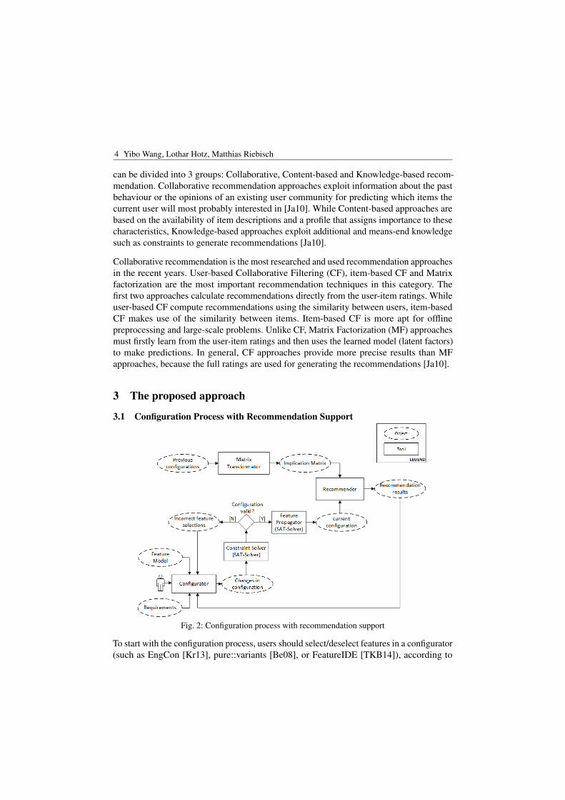
3.1 Configuration Process with Recommendation Support
Fig. 2: Configuration process with recommendation support
To start with the configuration process, users should select/deselect features in a configurator(such as EngCon [Kr13], pure::variants [Be08], or FeatureIDE [TKB14]), according to
Feature-based Recommendation 5
their individual requirements. The configurator presents the feature model graphically andenables interaction with users. The feature selections could lead to some changes in aconfiguration. Then, its validity will be checked by the constraint solver. If it is invalid,incorrect feature selections will be shown in the configurator and should be corrected byusers. Otherwise, the feature propagator starts to propagate the user’s selections onto otherfeatures. The current configuration after feature propagation (the lower part of Figure 2)becomes one part of the input for the recommender. The other part (the upper part ofFigure 2) comes from the matrix transformation of previous configurations (more detailsin the following sections). Finally, the recommendation results will be generated by therecommender and given to users. Thus, the recommendations will be considered in thefurther configuration iterations.
3.2 Choosing Recommender Techniques
In our approach, one input for the recommender system are previous configurations. Theyare very similar to user-item ratings in the similarity-based collaborative filtering approaches.Thus, we initially choose Collaborative Filtering (in the following referred to as CF) asour recommender technique. Because of poor scalability in processing large numbersof configurations in the user-based CF, our approach is based on the item-based CF. Inaddition, we don’t use Matrix Factorization techniques (such as BRISMF in [Pe16]) toimprove the recommender, due to its poor performance in respect of run time (waiting timeof over 30 seconds to generate a recommendation), In realistic scenarios, users should get arecommendation instantly after the current configuration step.
3.3 Formal Definition
In this section, we describe the formal representation of a configuration and definitionsfor feature recommendation. We follow the basic definitions in [Pe16] and make someamendments and extensions.
A feature model FM = (F, R) consists of a tuple of feature states F= −1,0,1h and aset of feature constraints R = r1,r2, . . . ,rm, where h is the number of features and m thenumber of constraints. A feature has the state 1 if it has been selected (positive decided);-1 if it has been deselected (negative decided); 0 if it is has not been decided (undecided).A configuration~c for a given feature model FM is a tuple of states for all features, moreformally as~c = f1, f2, . . . , fh. A configuration is complete, iff each feature has a decidedstate (state= -1 or 1). A configuration is partial, iff it is not complete. In other words, itstill has some features in undecided states (state=0). According to their states, features in aconfiguration can be divided into 3 groups: PD (positive decided), ND (negative decided)and UD (undecided), such that PD ∩ ND ∩ UD = /0 and PD ∪ ND ∪ UD = ~c. Previousconfigurations (in the following referred to as PC) are a collection of valid configurationsfrom all existing products. In our work, it is represented as a matrix of n rows h columns,
6 Yibo Wang, Lothar Hotz, Matthias Riebisch
where n is the number of previous configurations and h the number of features. Thus, eachrow represents an existing configuration.
PC =
pc11 pc12 . . . pc1h...
.... . .
...pcn1 pcn2 . . . pcnh
(1)
Besides feature constraints directly defined in the feature model, additional feature relationscould also be derived from PC. We call this type of feature relations as feature implication.Given two features fx and fy, it gives a hint on how likely fy should also be selected, iffx has been selected [Ma14]. It is also known as the confidence between two items in theMarket Basket Analysis [TSK05]. The feature implication is reflexive and asymmetric.More formally, it is defined as4:
con f idence ( fxis given→ fy) =
| fx and fy|| fx|
(1)
The formula in the numerator counts the number of configurations in PC, which have bothfx and fy, while the formula in the denominator counts the number of configurations whichhave only fx. The calculated confidence is a rational number between 0 and 1. Dependingon its value, feature implication takes on different meanings, as described in table 1.
Tab. 1: Meaning of confidence
confidence ( fx→ fy) = 0 If fx is selected, fy is never selected.0 < confidence ( fx→ fy) < 1 If fx is selected, fy is sometimes selected.confidence ( fx→ fy) = 1 If fx is selected, fy is always selected.
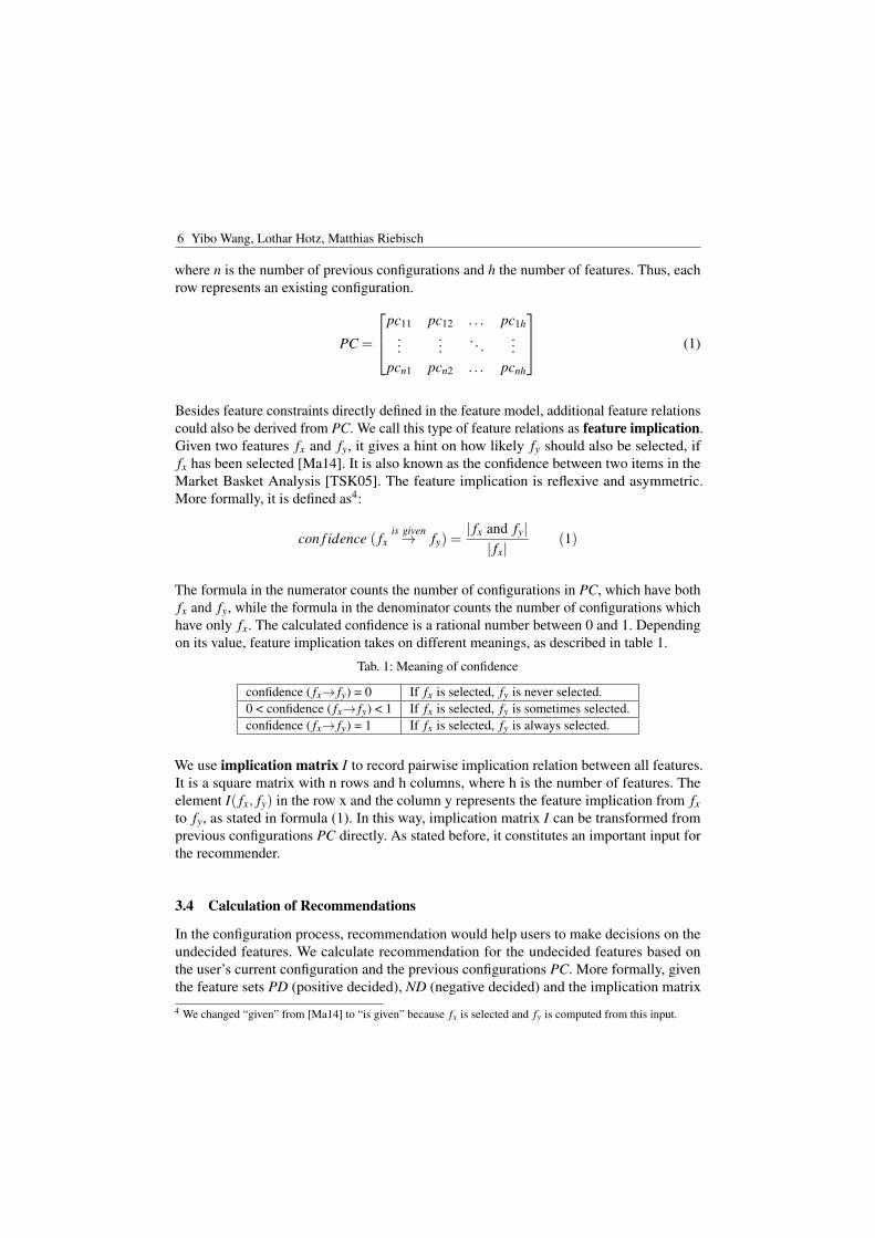
We use implication matrix I to record pairwise implication relation between all features.It is a square matrix with n rows and h columns, where h is the number of features. Theelement I( fx, fy) in the row x and the column y represents the feature implication from fxto fy, as stated in formula (1). In this way, implication matrix I can be transformed fromprevious configurations PC directly. As stated before, it constitutes an important input forthe recommender.
3.4 Calculation of Recommendations
In the configuration process, recommendation would help users to make decisions on theundecided features. We calculate recommendation for the undecided features based onthe user’s current configuration and the previous configurations PC. More formally, giventhe feature sets PD (positive decided), ND (negative decided) and the implication matrix
4 We changed “given” from [Ma14] to “is given” because fx is selected and fy is computed from this input.
Feature-based Recommendation 7
I, recommendation score for each feature fUD ∈ UD (undecided) will be calculated asfollowings:
score( fUD) = ‖∑
fPD∈PDI( fPD, fUD)
|PD| −∑
fND∈NDI( fND, fUD)
|ND| ‖ (2)
In the RHS of formula (2), the first part is the average feature implication from all positivedecided features to the undecided feature. The second part is the average feature implicationfrom all negative decided features to the undecided feature. The recommendation scoreis the absolute value of difference between the two parts. Its value is between 0 and 1.It reflects the relation from all decided features to the undecided feature. We can get therecommendation results based on it.
3.5 Implementation
We use the standard Apache-framework mahout5 to implement the proposed recommendersystem, because it is open-source and flexibly extensible. The state-of-the-art SAT-solverSAT4J6 is selected as our reasoning library to perform consistency checks. For the front-end, we are integrating our recommender with the product line configuration frameworkFeatureIDE[TKB14].
4 EvaluationWe evaluate our approach in light of its improvements for feature recommendation, incomparison to other traditional similarity-based CF recommenders. More precisely, wecompare the recommendation results achieved from our approach, with those from the used-based CF recommender (in the following referred to as user-CF) and from the item-basedrecommender (in the following referred to as item-CF).
4.1 Configuration Datasets
We use the first dataset7 from [Pe16] as previous configurations PC. It is a real-world dataset with 170 previous configurations. The feature model is composed of 1652 features andprovides a high-level representation of a product line in the business management contentfor a company. The configuration process is performed as customization of a specificproduct for each employee.
4.2 Experiment Design
To generate recommendations, the parameters for the user-based CF recommender (table 2)are set to the same values as those in [Pe16], because they are optimized for this data set.5 Recommender engine, https://mahout.apache.org/users/recommender/recommender-documentation.html6 SAT-solver, http://www.sat4j.org/7 ERP System under http://wwwiti.cs.uni-magdeburg.de/~jualves/PROFilE/#datasets
8 Yibo Wang, Lothar Hotz, Matthias Riebisch
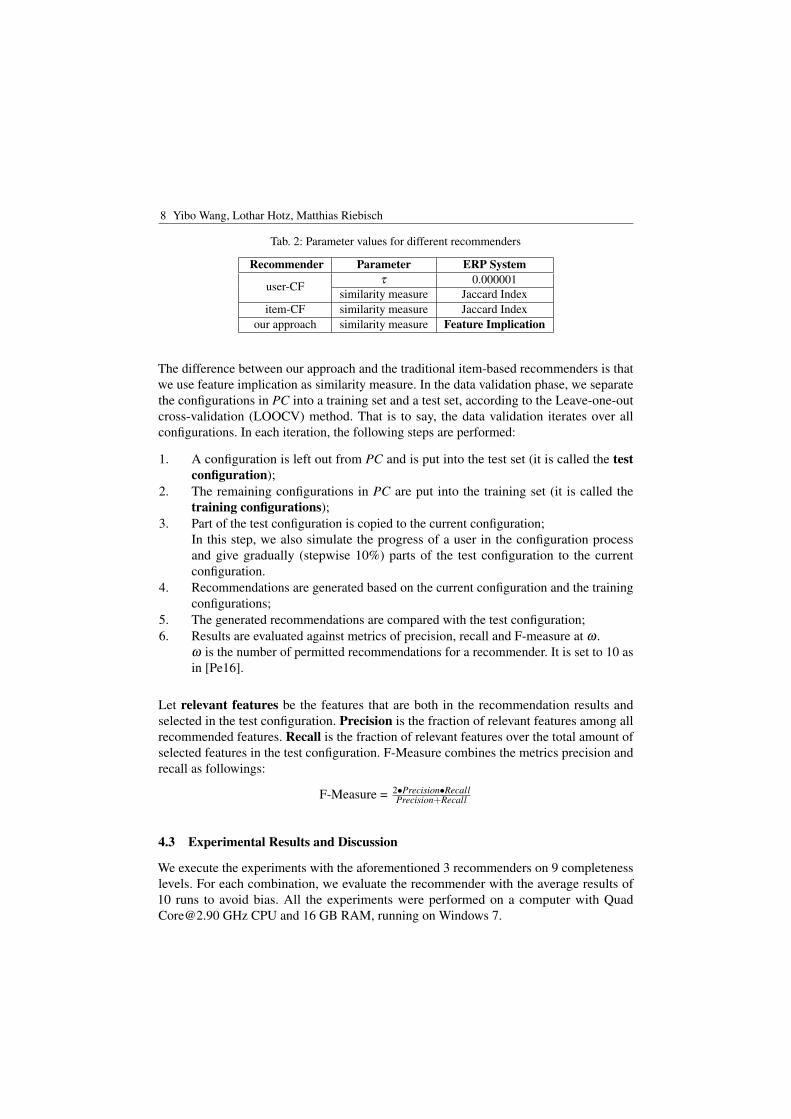
Tab. 2: Parameter values for different recommenders
Recommender Parameter ERP System
user-CF τ 0.000001similarity measure Jaccard Index
item-CF similarity measure Jaccard Indexour approach similarity measure Feature Implication
The difference between our approach and the traditional item-based recommenders is thatwe use feature implication as similarity measure. In the data validation phase, we separatethe configurations in PC into a training set and a test set, according to the Leave-one-outcross-validation (LOOCV) method. That is to say, the data validation iterates over allconfigurations. In each iteration, the following steps are performed:
1. A configuration is left out from PC and is put into the test set (it is called the testconfiguration);
2. The remaining configurations in PC are put into the training set (it is called thetraining configurations);
3. Part of the test configuration is copied to the current configuration;In this step, we also simulate the progress of a user in the configuration processand give gradually (stepwise 10%) parts of the test configuration to the currentconfiguration.
4. Recommendations are generated based on the current configuration and the trainingconfigurations;
5. The generated recommendations are compared with the test configuration;6. Results are evaluated against metrics of precision, recall and F-measure at ω .
ω is the number of permitted recommendations for a recommender. It is set to 10 asin [Pe16].
Let relevant features be the features that are both in the recommendation results andselected in the test configuration. Precision is the fraction of relevant features among allrecommended features. Recall is the fraction of relevant features over the total amount ofselected features in the test configuration. F-Measure combines the metrics precision andrecall as followings:
F-Measure = 2•Precision•RecallPrecision+Recall
4.3 Experimental Results and Discussion
We execute the experiments with the aforementioned 3 recommenders on 9 completenesslevels. For each combination, we evaluate the recommender with the average results of10 runs to avoid bias. All the experiments were performed on a computer with [email protected] GHz CPU and 16 GB RAM, running on Windows 7.
Feature-based Recommendation 9
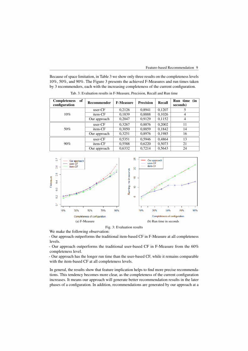
Because of space limitation, in Table 3 we show only three results on the completeness levels10%, 50%, and 90%. The Figure 3 presents the achieved F-Measures and run times takenby 3 recommenders, each with the increasing completeness of the current configuration.
Tab. 3: Evaluation results in F-Measure, Precision, Recall and Run time
Completeness ofconfiguration Recommender F-Measure Precision Recall Run time (in
seconds)
10%user-CF 0,2126 0,8941 0,1207 5item-CF 0,1839 0,8888 0,1026 4
Our approach 0,2047 0,9129 0,1152 4
50%user-CF 0,3267 0,8876 0,2002 11item-CF 0,3050 0,8859 0,1842 14
Our approach 0,3251 0,8976 0,1985 16
90%user-CF 0,5351 0,5946 0,4864 13item-CF 0,5588 0,6220 0,5073 21
Our approach 0,6332 0,7214 0,5643 24
(a) F-Measure (b) Run time in seconds
Fig. 3: Evaluation resultsWe make the following observation:- Our approach outperforms the traditional item-based CF in F-Measure at all completenesslevels.- Our approach outperforms the traditional user-based CF in F-Measure from the 60%completeness level.- Our approach has the longer run time than the user-based CF, while it remains comparablewith the item-based CF at all completeness levels.
In general, the results show that feature implication helps to find more precise recommenda-tions. This tendency becomes more clear, as the completeness of the current configurationincreases. It means our approach will generate better recommendation results in the laterphases of a configuration. In addition, recommendations are generated by our approach at a
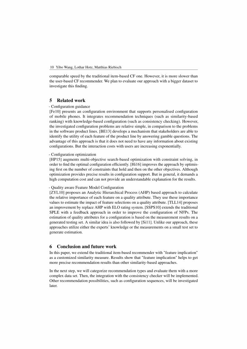
10 Yibo Wang, Lothar Hotz, Matthias Riebisch
comparable speed by the traditional item-based CF one. However, it is more slower thanthe user-based CF recommender. We plan to evaluate our approach with a bigger dataset toinvestigate this finding.
5 Related work- Configuration guidance[Fe10] presents an configuration environment that supports personalised configurationof mobile phones. It integrates recommendation techniques (such as similarity-basedranking) with knowledge-based configuration (such as consistency checking). However,the investigated configuration problems are relative simple, in comparison to the problemsin the software product lines. [BE13] develops a mechanism that stakeholders are able toidentify the utility of each feature of the product line by answering gamble questions. Theadvantage of this approach is that it does not need to have any information about existingconfigurations. But the interaction costs with users are increasing exponentially.
- Configuration optimization[HP15] augments multi-objective search-based optimization with constraint solving, inorder to find the optimal configuration efficiently. [Hi16] improves the approach by optimis-ing first on the number of constraints that hold and then on the other objectives. Althoughoptimization provides precise results in configuration support. But in general, it demands ahigh computation cost and can not provide an understandable explanation for the results.
- Quality aware Feature Model Configuration[ZYL10] proposes an Analytic Hierarchical Process (AHP) based approach to calculatethe relative importance of each feature on a quality attribute. They use these importancevalues to estimate the impact of feature selections on a quality attribute. [TLL14] proposesan improvement by replace AHP with ELO rating system. [SSPS10] extends the traditionalSPLE with a feedback approach in order to improve the configuration of NFPs. Theestimation of quality attributes for a configuration is based on the measurement results on agenerated testing set. A similar idea is also followed by [Si11]. Unlike our approach, theseapproaches utilize either the experts’ knowledge or the measurements on a small test set togenerate estimation.
6 Conclusion and future workIn this paper, we extend the traditional item-based recommender with "feature implication"as a customized similarity measure. Results show that "feature implication" helps to getmore precise recommendation results than other similarity-based approaches.
In the next step, we will categorize recommendation types and evaluate them with a morecomplex data set. Then, the integration with the consistency checker will be implemented.Other recommendation possibilities, such as configuration sequences, will be investigatedlater.
Feature-based Recommendation 11
References[Be08] Beuche, Danilo: Modeling and building software product lines with pure::variants. Pro-
ceedings - 12th International Software Product Line Conference, SPLC 2008, p. 358,2008.
[BE13] Bagheri, Ebrahim; Ensan, Faezeh: Dynamic decision models for staged software productline configuration. Requirements Engineering, 19(2):187–212, 2013.
[Cz12] Czarnecki, Krzysztof; Grünbacher, Paul; Rabiser, Rick; Schmid, Klaus; Wasowski, An-drzej: Cool features and tough decisions. In: VaMoS ’12 The 6th International Workshopon Variability Modeling of Software-Intensive Systems. ACM Press, New York, NewYork, USA, pp. 173–182, 2012.
[Fe10] Felfernig, Alexander; Mandl, Monika; Tiihonen, Juha; Schubert, Monika; Leitner, Ger-hard: Personalized user interfaces for product configuration. In: Proceedings of the 15thinternational conference on Intelligent user interfaces - IUI ’10. ACM Press, New York,New York, USA, p. 317, 2010.
[Hi16] Hierons, Robert M; Li, Miqing; Liu, Xiaohui; Segura, Sergio; Zheng, Wei: SIP: OptimalProduct Selection from Feature Models Using Many-Objective Evolutionary Optimization.ACM Transactions on Software Engineering and Methodology, 25(2):1–39, April 2016.
[HP15] Henard, Christopher; Papadakis, Mike: Combining multi-objective search and constraintsolving for configuring large software product lines. In: ICSE’ 15 Proceedings of the 37thInternational Conference on Software Engineering. pp. 517–528, 2015.
[Ja10] Jannach, Dietmar; Zanker, Markus; Felfernig, Alexander; Friedrich, Gerhard: Recom-mender Systems. Cambridge University Press, Cambridge, 2010.
[Ka90] Kang, K.; Cohen, S.; Hess, J.; Novak, W.; Peterson, S.: Feature-Oriented Domain Analysis(FODA) Feasibility Study. Technical Report CMU/SEI-90-TR-021, 1990.
[KO14] Karatas , Ahmet Serkan; Oguztuzun, Halit: Attribute-based variability in feature models.Requirements Engineering, pp. 185–208, 2014.
[Kr13] Krebs, T.: EngCon. In (Felfernig, A.; Hotz, L.; Bagley, C.; Tiihonen, J., eds): Knowledge-based Configuration – From Research to Business Cases, chapter 23, pp. 337–346. MorganKaufmann Publishers, 2013.
[Ma14] Martinez, Jabier; Ziadi, Tewfik; Mazo, Raul; Bissyande, Tegawende F.; Klein, Jacques;Traon, Yves Le: Feature Relations Graphs: A Visualisation Paradigm for Feature Con-straints in Software Product Lines. In: 2014 Second IEEE Working Conference onSoftware Visualization. IEEE, pp. 50–59, sep 2014.
[Pe16] Pereira, Juliana Alves; Matuszyk, Pawel; Krieter, Sebastian; Spiliopoulou, Myra; Saake,Gunter: A feature-based personalized recommender system for product-line configuration.i, ACM Press, New York, New York, USA, pp. 120–131, 2016.
[Si11] Siegmund, Norbert; Rosenmüller, Marko; Kuhlemann, Martin; Kästner, Christian; Apel,Sven; Saake, Gunter: SPL Conqueror: Toward optimization of non-functional propertiesin software product lines. Software Quality Journal, 20(3-4):487–517, jun 2011.
12 Yibo Wang, Lothar Hotz, Matthias Riebisch
[SSPS10] Sincero, Julio; Schröder-Preikschat, Wolfgang; Spinczyk, Olaf: Approaching non-functional properties of software product lines: Learning from products. Proceedings -Asia-Pacific Software Engineering Conference, APSEC, pp. 147–155, 2010.
[TKB14] Thüm, T; Kästner, C; Benduhn, F: FeatureIDE: An extensible framework for feature-oriented software development. Science of Computer Programming, 79:70–85, 2014.
[TLL14] Tan, Lei; Lin, Yuqing; Liu, Li: Quality Ranking of Features in Software Product LineEngineering. In: 2014 21st Asia-Pacific Software Engineering Conference. volume 2.IEEE, pp. 57–62, dec 2014.
[TSK05] Tan, Pang-Ning; Steinbach, Michael; Kumar, Vipin: Introduction to Data Mining, (FirstEdition). Addison-Wesley Longman Publishing Co., Inc., Boston, MA, USA, 2005.
[ZYL10] Zhang, Guoheng; Ye, Huilin; Lin, Yuqing: Quality attributes assessment for feature-basedproduct configuration in software product line. In: Proceedings - Asia-Pacific SoftwareEngineering Conference, APSEC. pp. 137–146, 2010.
cbe
Herausgeber et al. (Hrsg.): Modellbasierte Entwicklung eingebetteter Systeme,Lecture Notes in Informatics (LNI), Gesellschaft für Informatik, Bonn 2017 11
Feature-oriented Domain-specific Languages
Philipp Ulsamer1, Tobias Fertig2, Peter Braun3
Abstract: Domain-specific Languages (DSL) describe applications of particular domainsthat can be understood by domain experts. However, common users have to learn a newdomain language. Moreover, developing similar software products from scratch is a timeconsuming and tedious task. Therefore, we developed an internal DSL to describe RESTfulsystems. In order to use that one must have very good knowledge about REST. Featuremodels are a common paradigm in Product Line Engineering to represent the featuresof the products as reusable parts. They can be easily communicated with customers.That is why we have extended our approach with a model-to-model transformation. Thistransformation provides a model for an underlying REST generator. While a model-to-code(M2C) generator is developed domain-specific, excluding expansion by a new domain,our approach is to make it more efficient than developing a M2C generator for everysingle domain. So that non-experts can configure REST solutions by using feature modelswithout knowledge of REST.
Keywords: MDSD; DSL; REST; Hypermedia; RESTful; SPL; Domain Engineering; FeatureModeling; Model Transformation; M2M
1 Introduction
Model manipulation plays the central role in Model-Driven Engineering. In 2015 wepresented our project Generating Mobile Applications with RESTful Architecture(GeMARA) [SB15] in which we proposed a model-driven approach for creatingRESTful APIs. For the purpose of focusing on a particular domain, we developedan external Domain-specific Language (DSL) using the Eclipse plugin Xtext [EB10]for defining the grammar of the DSL and the programming language Xtend [Be13]to implement the software generator. The limited expressiveness and the fluencyfrom combined individual expressions, and the domain focus makes our DSL easy tobe understood by domain experts [Fo10]. However, there are several shortcomings.A user has to learn a new language which requires considerable time to learn.
1 Univesity Of Applied Science Wuerzburg-Schweinfurt, FIW, Sanderheinrichsleitenweg 20, 97074Wuerzburg, Germany [email protected]
2 Univesity Of Applied Science Wuerzburg-Schweinfurt, FIW, Sanderheinrichsleitenweg 20, 97074Wuerzburg, Germany [email protected]
3 Univesity Of Applied Science Wuerzburg-Schweinfurt, FIW, Sanderheinrichsleitenweg 20, 97074Wuerzburg, Germany [email protected]
12 Philipp Ulsamer, Tobias Fertig, Peter Braun
Also, developing, evolving, and maintaining complex external DSLs requires signifi-cant effort. As our project matured, we switched to an internal DSL using Java asthe General Purpose Programming Language (GPL) [SB15].
Product Line Engineering (PLE) has the goal of developing software systems fromreusable parts instead of developing them from scratch [Ap13]. The feature-orientedapproach was originally proposed as part of the Feature-Oriented Domain Analysis(FODA) method [Ka90]. The main idea is to express every product configuration ona higher level of abstraction using the feature models paradigm. While developmentis easier to implement by Java developers, the knowledge of REST is indispensableto understand the domain in our GeMARA project.
We address this problem by extending this approach with a model-to-model (M2M)transformation. Features of a given feature model will be transformed to a RESTfulfinite-state machine (ε-NFA) [ZBD11]. Connecting those features will lead to anε-NFA that represents a valid specification of the product. Using M2M transfor-mation allows less experienced users to define their product using feature-basedconfiguration files. Therefore, the user will not need any knowledge about describingRESTful systems as ε-NFAs. Additionally, the automatic generation of programcode by a generator is characteristic of generative programming. This automaticgeneration is also known as model-to-code (M2C) transformation. In order to carryout an M2C transformation, a generator must be developed for each individualdomain, the development effort which is always different and thus represents atime-consuming task. The M2M transformation provides a model for the underlyingREST generator in GeMARA, which performs a model transformation on theincoming feature model. This facilitates the addition of various forms of a domainand their maintenance.
First, we will summarize related work and confirm that feature modeling used as anabstraction in hypermedia for M2M transformation is a missing task. Afterwardswe will discuss challenges of using REST in model transformation. Furthermore,we will propose our approaches for solving these challenges. Finally, we will give ashort outlook and discuss our future work.
Feature-oriented Domain-specific Languages 13
2 Related Work
Voelter and Viser propose the method of using DSLs in PLE [VV11]. They show howDSLs can fill the gap between feature modeling and programming languages, whena feature model exceeds its limit. Expressing complex features in their behavior toeach other is not possible with feature models. Feature models can be used to selectamong a set of few predefined behaviors, composition rules or rationale in FODA[Ka90]. Picturing all possible behaviors would lead to a confusing feature model.In order to fix this issue, the behavior could be implemented in a GPL that wouldlower the abstraction that feature models offer, reducing the understandability, aswell as the possibility for non-programmers to participate. DSLs can counteractand be the mediator between the composition rules and the lack of restrictionsof a GPL. A missing topic is the abstraction via M2M transformation. While thetransformation of models is under the control of the domain engineer when workingwith DSLs we need to lighten the usage of the DSL.
Cuadrado and Molina deal with embedded DSLs and its model transformation intheir work. [CM07] A key aspect of MDSD is Metamodeling, which defines theabstract syntax of a DSL. Since graphical editors are the most favorable way todefine Metamodels, developing one is a time-consuming task. Nevertheless, theypropose a M2M transformation approach transforming a UML model into a Javamodel. Our approach focuses on feature models to grant a certain degree of reuseof our features. For a definition of a new feature selection, you only have to choosebetween a preconfigured set of allowed feature combinations instead of defining aUML for each selection.
3 GeMARA
The goal of our research project is to develop automated Generators for distributedMobile Applications based on RESTful Architecture (GeMARA) by providing amodel-driven approach. Accordingly, applications are no longer described as sourcecode, but as an abstract model from which source code and other artifacts aregenerated.
We proposed our approach in 2015 in [SB15]. Back then we were able to generateRESTful APIs including the persistence layer. Our generators were written withXtext [EB10] and Xtend [Be13]. However, as our project matured, the maintenanceof our generators got a more and more time consuming task. Therefore, we cut loosefrom Xtext and Xtend and developed our own internal DSL in Java. The new DSLdescribes RESTful Systems as finite state machines (ε-NFA) according to Zusak etal. [ZBD11]:
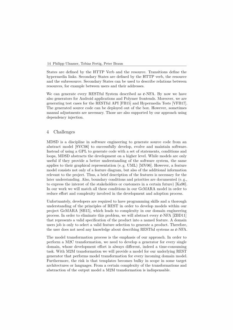
14 Philipp Ulsamer, Tobias Fertig, Peter Braun
States are defined by the HTTP Verb and the resource. Transitions define thehypermedia links. Secondary States are defined by the HTTP verb, the resourceand the subresource. Secondary States can be used to describe relations betweenresources, for example between users and their addresses.
We can generate every RESTful System described as ε-NFA. By now we havealso generators for Android applications and Polymer frontends. Moreover, we aregenerating test cases for the RESTful API [FB15] and Hypermedia Tests [VFB17].The generated source code can be deployed out of the box. However, sometimesmanual adjustments are necessary. Those are also supported by our approach usingdependency injection.
4 Challenges
MDSD is a discipline in software engineering to generate source code from anabstract model [SVC06] to successfully develop, evolve and maintain software.Instead of using a GPL to generate code with a set of statements, conditions andloops, MDSD abstracts the development on a higher level. While models are onlyuseful if they provide a better understanding of the software system, the sameapplies to their graphical representation (e. g. UML) [MV06]. However, a featuremodel consists not only of a feature diagram, but also of the additional informationrelevant to the project. Thus, a brief description of the features is necessary for thelater understanding. Also, boundary conditions and priorities are documented (e. g.,to express the interest of the stakeholders or customers in a certain future) [Ka90].In our work we will match all these conditions in our GeMARA model in order toreduce effort and complexity involved in the development and adoption process.
Unfortuantely, developers are required to have programming skills and a thoroughunderstanding of the principles of REST in order to develop models within ourproject GeMARA [SB15], which leads to complexity in our domain engineeringprocess. In order to eliminate this problem, we will abstract every ε-NFA [ZBD11]that represents a valid specification of the product into a named feature. A domainusers job is only to select a valid feature selection to generate a product. Therefore,the user does not need any knowledge about describing RESTful systems as ε-NFA.
The model transformation process is the emphasis of our approach. In order toperform a M2C transformation, we need to develop a generator for every singledomain, whose development effort is always different, indeed a time-consumingtask. With M2M transformation we will provide a model for our underlying RESTgenerator that performs model transformation for every incoming domain model.Furthermore, the risk is that templates becomes bulky in scope in some targetarchitectures or languages. From a certain complexity of the transformations andabstraction of the output model a M2M transformation is indispensable.
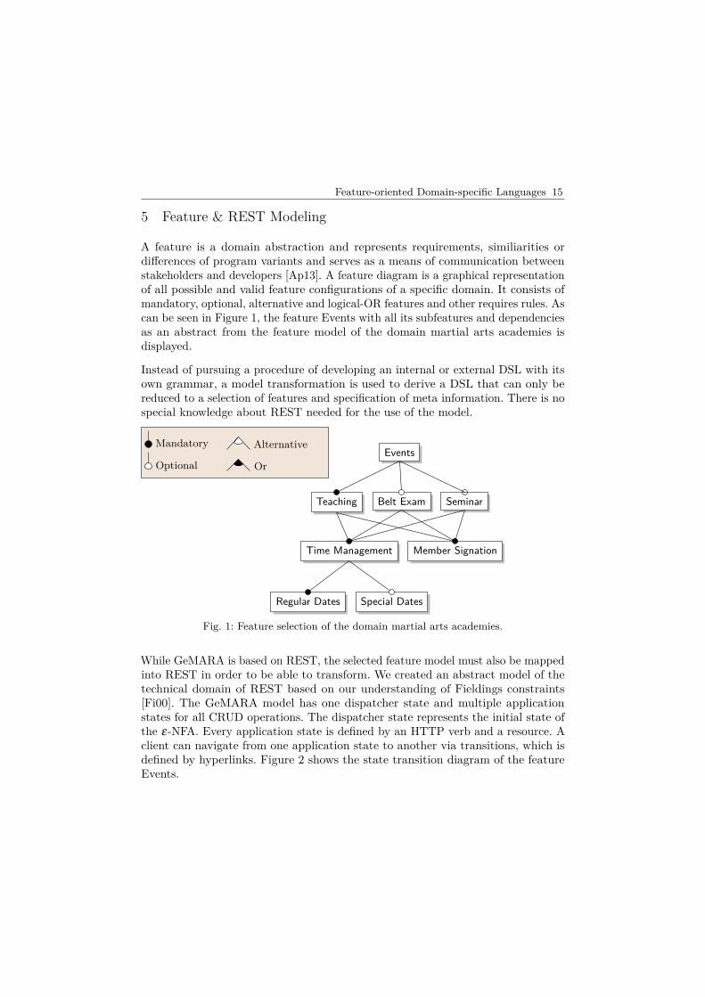
Feature-oriented Domain-specific Languages 15
5 Feature & REST Modeling
A feature is a domain abstraction and represents requirements, similiarities ordifferences of program variants and serves as a means of communication betweenstakeholders and developers [Ap13]. A feature diagram is a graphical representationof all possible and valid feature configurations of a specific domain. It consists ofmandatory, optional, alternative and logical-OR features and other requires rules. Ascan be seen in Figure 1, the feature Events with all its subfeatures and dependenciesas an abstract from the feature model of the domain martial arts academies isdisplayed.
Instead of pursuing a procedure of developing an internal or external DSL with itsown grammar, a model transformation is used to derive a DSL that can only bereduced to a selection of features and specification of meta information. There is nospecial knowledge about REST needed for the use of the model.
Events
Teaching Belt Exam Seminar
Time Management Member Signation
Regular Dates Special Dates
Mandatory Alternative
Optional Or
Fig. 1: Feature selection of the domain martial arts academies.
While GeMARA is based on REST, the selected feature model must also be mappedinto REST in order to be able to transform. We created an abstract model of thetechnical domain of REST based on our understanding of Fieldings constraints[Fi00]. The GeMARA model has one dispatcher state and multiple applicationstates for all CRUD operations. The dispatcher state represents the initial state ofthe ε-NFA. Every application state is defined by an HTTP verb and a resource. Aclient can navigate from one application state to another via transitions, which isdefined by hyperlinks. Figure 2 shows the state transition diagram of the featureEvents.

16 Philipp Ulsamer, Tobias Fertig, Peter Braun
Start Dispatcher
GET Events GET Event
DELETE Event
PUT Event
POST Event
Fig. 2: Example of a ε-NFA of the resource Event.
We put a new domain model on top of the technical REST model. Every featurein a domain model is represented as an ε-NFA using the given feature type bythe feature model. A feature type represents which HTTP verbs are supported forevery required resource. This allows the creator of the domain to limit the CRUDoperations that can be used on a resource. Thus, a feature of a valid feature selectionmay have multiple resources. These are usually generated separately from eachother. With the help of Secondary States, the ε-NFA of the resources are linkedtogether in order to be able to fully describe a feature.
6 Model Transformation
Our M2M transformation consists of two steps. Firstly, the domain developer hasto provide a feature factory and a feature validator for their domain. Secondly, theuser has to define the required features within a YAML file.
Our generic implementation parses the YAML file and uses the given featurevalidator of this domain. If the configuration of the user passes the validatorstests it can be transformed into a GeMARA model. The tests checks whether thecombination of mandatory, optional and alternative features is valid. Therefore, thetransformer translates the YAML file into an internal representation of features.The feature factory of the developer is used within this step. The developer has todefine the ε-NFA for every feature a user can define in his feature factory.
We divided the transformation process into three steps: resource, state and transitiontransformation. Our Transformer uses the generic sub-transformers to create aGeMARA model that can then be used to generate the RESTful System. (seeFigure 3).
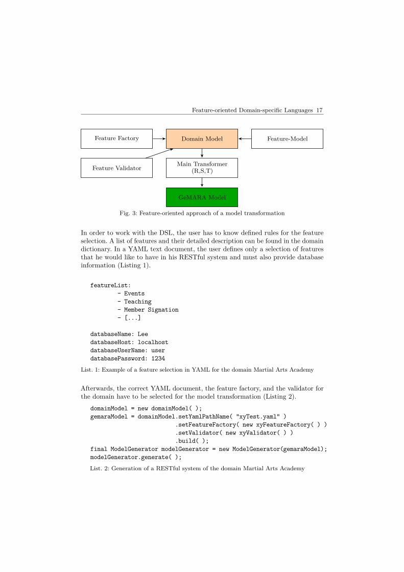
Feature-oriented Domain-specific Languages 17
Feature Factory
Feature Validator
Domain Model Feature-Model
Main Transformer(R,S,T)
GeMARA Model
Fig. 3: Feature-oriented approach of a model transformation
In order to work with the DSL, the user has to know defined rules for the featureselection. A list of features and their detailed description can be found in the domaindictionary. In a YAML text document, the user defines only a selection of featuresthat he would like to have in his RESTful system and must also provide databaseinformation (Listing 1).
featureList:- Events- Teaching- Member Signation- [...]
databaseName: LeedatabaseHost: localhostdatabaseUserName: userdatabasePassword: 1234
List. 1: Example of a feature selection in YAML for the domain Martial Arts Academy
Afterwards, the correct YAML document, the feature factory, and the validator forthe domain have to be selected for the model transformation (Listing 2).
domainModel = new domainModel( );gemaraModel = domainModel.setYamlPathName( "xyTest.yaml" )
.setFeatureFactory( new xyFeatureFactory( ) )
.setValidator( new xyValidator( ) )
.build( );final ModelGenerator modelGenerator = new ModelGenerator(gemaraModel);modelGenerator.generate( );
List. 2: Generation of a RESTful system of the domain Martial Arts Academy
18 Philipp Ulsamer, Tobias Fertig, Peter Braun
7 Discussion
Our vision is to generate RESTful Systems that can be configured by users whoare less experienced in programming or REST. Feature models have been shown tobe generally understandable, to illustrate functions, their similarities, differencesand restrictions. By configuring different models, reuse is possible because manyfeatures are mandatory components of each product.
Previously, we had to develop the resources, states and transitions separately. Themodel transformation allows us to draw their development to a higher level ofabstraction that they can be generated. This can reduce manual implementations aswell as repetitive routine tasks that would normally occur in an M2C approach. Inaddition, the development effort of a transformation in its extension is much moreefficient than code generation. Not only does the domain model allow additionaldomains to be modeled by a few lines of code, because most of the components ofthe model transformation can be reused, but the variability of the feature modelprovides a multitude of possibilities, such as the user of a domain by specifying afeature selection, it can generate a complete RESTful System. A similar developmentwith the M2C transformation would require the development of code generators foreach domain. This would also be more time consuming than our approach.
The abstract representation of a model transformation not only makes the devel-opment of a domain model simpler, but also its use. The transformation from thedomain model to a GeMARA model simplifies the generation of a RESTful Systemby only having to make a selection of features after a specific domain policy. Thefeature-oriented DSL only requires the user to enter a list of features in a YAMLtext document and to provide additional meta-information.
8 Outlook
The development of an M2M transformation has shown that a higher level ofabstraction can automate many recurring tasks. Even if its enhancement requiresless implementation than an M2C transformation, defining features in a FeatureFactory of the domain model is still a time-consuming but undemanding task. Inturn, a code generator could be written that generates the information for a feature,its resources and attributes. Also, for the development of the Feature Validator of adomain, a separate DSL could be written to simplify and streamline statementsrelated to the constraints of a feature model and minimize error proneness. Thus,the extension of a domain could also be reduced to a few lines of code. Finally,language workbenches are becoming more and more powerful and user friendly[Fo05]. Their development and offer to tools far exceeds the current development ofDSLs. Future work will focus on M2M transformation using language workbenchesfor our RESTful systems.
Feature-oriented Domain-specific Languages 19
References
[Ap13] Apel, S.; Batory, D.; Kstner, C.; Saake, G.: Feature-Oriented SoftwareProduct Lines: Concepts and Implementation. Springer Publishing Com-pany, Incorporated, 2013.
[Be13] Bettini, L.: Implementing Domain-Specific Languages with Xtext andXtend. Packt Publishing, 2013.
[CM07] Cuadrado, J. S.; Molina, J. G.: Building Domain-Specific Languages forModel-Driven Development. IEEE Software 24/5, 2007.
[EB10] Eysholdt, M.; Behrens, H.: Xtext: Implement Your Language Faster Thanthe Quick and Dirty Way. In: Proceedings of the ACM InternationalConference Companion on Object Oriented Programming Systems Lan-guages and Applications Companion. OOPSLA ’10, ACM, Reno/Tahoe,Nevada, USA, pp. 307–309, 2010.
[FB15] Fertig, T.; Braun, P.: Model-driven Testing of RESTful APIs. In: Pro-ceedings of the 24th International Conference on World Wide WebCompanion. WWW ’15 Companion, International World Wide WebConferences Steering Committee, Florence, Italy, pp. 1497–1502, 2015.
[Fi00] Fielding, R.: REST: Architectural Styles and the Design of Network-basedSoftware Architectures, Doctoral dissertation, University of California,Irvine, 2000.
[Fo05] Fowler, M.: Language Workbenches: The Killer-App for Domain SpecificLanguages?/, 2005, URL: http://www.martinfowler.com/articles/languageWorkbench.html.
[Fo10] Fowler, M.: Domain Specific Languages. Addison-Wesley Professional,2010.
[Ka90] Kang, K. C.; Cohen, S. G.; Hess, J. A.; Novak, W. E.; Peterson, A. S.:Feature-Oriented Domain Analysis (FODA) Feasibility Study, tech. rep.,Carnegie-Mellon University Software Engineering Institute, Nov. 1990.
[MV06] Mens, T.; Van Gorp, P.: A Taxonomy of Model Transformation. Electron.Notes Theor. Comput. Sci. 152/, pp. 125–142, Mar. 2006.
[SB15] Schreibmann, V.; Braun, P.: Model-Driven Development of RESTful APIs.In: Proceedings of the 11th International Conference of Web InformationSystems and Technologies, Lisbon, Portugal. INSTICC, SciTePress, pp. 5–14, May 2015.
[SVC06] Stahl, T.; Voelter, M.; Czarnecki, K.: Model-Driven Software Devel-opment: Technology, Engineering, Management. John Wiley & Sons,2006.
20 Philipp Ulsamer, Tobias Fertig, Peter Braun
[VFB17] Vu, H.; Fertig, T.; Braun, P.: Towards model-driven hypermedia testingfor RESTful systems. In: WEBIST 2017 - Proceedings of the 13th In-ternational Conference on Web Information Systems and Technologies.2017.
[VV11] Völter, M.; Visser, E.: Product Line Engineering Using Domain-SpecificLanguages. In: Software Product Lines - 15th International Conference,SPLC 2011, Munich, Germany, August 22-26, 2011. Pp. 70–79, 2011.
[ZBD11] Zuzak, I.; Budiselic, I.; Delac, G.: Formal Modeling of RESTful SystemsUsing Finite-State Machines. In (Auer, S.; Díaz, O.; Papadopoulos, G. A.,eds.). Springer Berlin Heidelberg, chap. Web Engineering: 11th Inter-national Conference, ICWE 2011, Paphos, Cyprus, June 20-24, 2011,pp. 346–360, 2011.

cbe
Michaela Huhn, Hardi Hungar, Matthias Riebisch, Sebastian Voss (Hrsg.): MBEES 2018,Lecture Notes in Informatics (LNI), Gesellschaft für Informatik, Bonn 2017 1
Using PLC Programming Languages for Test-CaseSpecification of Hardware-in-the-loop Tests
David Thönnessen1, Stefan Kowalewski2
Abstract: Testing cyber-physical production systems (CPPSs) pose particular problems to testingcontrol systems like Programmable Logic Controllers (PLCs). CPPS continuously underlie reconfigu-ration such that testing before commissioning is no longer sufficient. Because of that, it is crucialto have a testing environment supporting adaptive test cases and allowing for an efficient test casespecification. Our approach consists of a modular specification architecture using slightly extendedPLC programming languages. By doing this, we avoid the change of methodology observed whenusing dedicated test languages and corresponding tools. Our hypothesis is that this will lead to fasterand more reliably changeable test case descriptions and thus will create the desired agility.
Keywords: Programmable Logic Controller; Automation; Testing; Simulation
1 Introduction
This paper deals with testing of cyber-physical production systems (CPPSs) [BtHVH14]before and after commissioning. Testing CPPSs is essential because these systems underliereconfiguration and changing environmental conditions. Our approach is to optimizeHardware-in-the-Loop (HiL) testing for the application in automation [Gu07] and allowtesting after commissioning a control system. With this goal, we extended ProgrammableLogic Controller (PLC) programming languages [IE13] to qualify them for test casespecification. We will describe the test process as well as the introduced language extensionsin Section 4. Our initial scenario consists of a plant controlled by a PLC. The plant providessensor information that are captured by the PLC. A control program processes the inputsand generates outputs for the actuators of the plant. We will call the PLC more generallySystem Under Test (SUT) in this scenario. When testing with HiL, the so-called HiLsimulator replaces the plant. It simulates the sensors of the plant and, in return, evaluatesthe control signals of the SUT, in the following named actual signals. One approach forevaluating these signals is to compare them to a specification as done in the tools WCOMP orArttest [Wi17, Zh07]. The tester has to implement this specification defining the referencebehavior of the SUT as a function of its output signals. A complete specification allowscalculating a reference signal for every actual signal. Within the HiL simulator we compare1 RWTH Aachen University, Informatik 11 - Embedded Software, Ahornstraße 55, 52074 Aachen, Germany
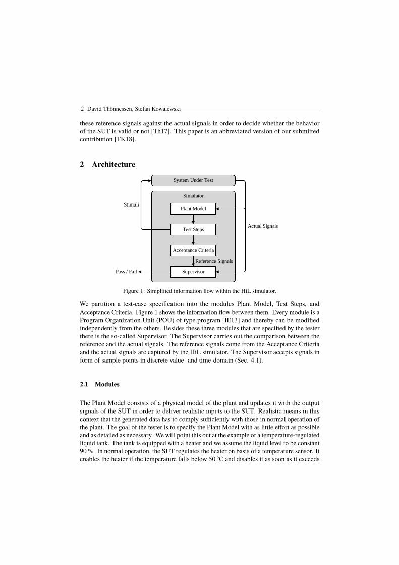
2 David Thönnessen, Stefan Kowalewski
these reference signals against the actual signals in order to decide whether the behaviorof the SUT is valid or not [Th17]. This paper is an abbreviated version of our submittedcontribution [TK18].
2 Architecture
Simulator
System Under Test
Test Steps
Acceptance Criteria
Plant Model
SupervisorPass / Fail
Stimuli
Actual Signals
Reference Signals
Figure 1: Simplified information flow within the HiL simulator.
We partition a test-case specification into the modules Plant Model, Test Steps, andAcceptance Criteria. Figure 1 shows the information flow between them. Every module is aProgram Organization Unit (POU) of type program [IE13] and thereby can be modifiedindependently from the others. Besides these three modules that are specified by the testerthere is the so-called Supervisor. The Supervisor carries out the comparison between thereference and the actual signals. The reference signals come from the Acceptance Criteriaand the actual signals are captured by the HiL simulator. The Supervisor accepts signals inform of sample points in discrete value- and time-domain (Sec. 4.1).
2.1 Modules
The Plant Model consists of a physical model of the plant and updates it with the outputsignals of the SUT in order to deliver realistic inputs to the SUT. Realistic means in thiscontext that the generated data has to comply sufficiently with those in normal operation ofthe plant. The goal of the tester is to specify the Plant Model with as little effort as possibleand as detailed as necessary. We will point this out at the example of a temperature-regulatedliquid tank. The tank is equipped with a heater and we assume the liquid level to be constant90 %. In normal operation, the SUT regulates the heater on basis of a temperature sensor. Itenables the heater if the temperature falls below 50 C and disables it as soon as it exceeds
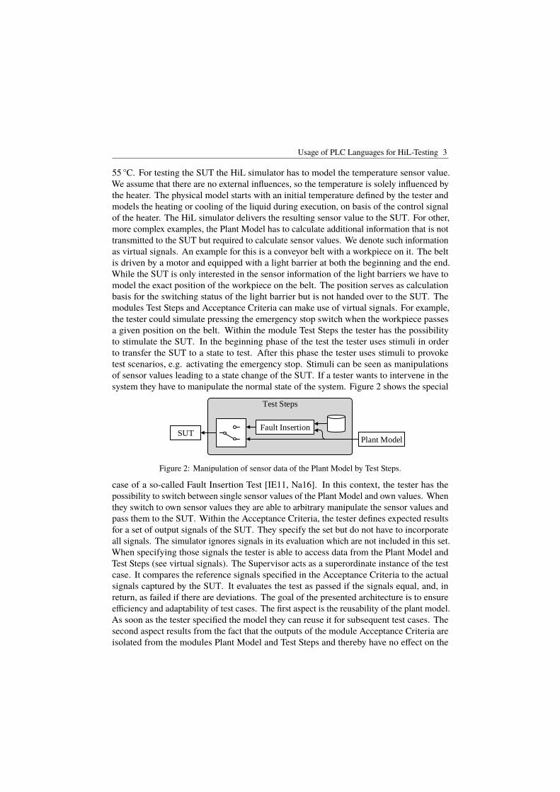
Usage of PLC Languages for HiL-Testing 3
55 C. For testing the SUT the HiL simulator has to model the temperature sensor value.We assume that there are no external influences, so the temperature is solely influenced bythe heater. The physical model starts with an initial temperature defined by the tester andmodels the heating or cooling of the liquid during execution, on basis of the control signalof the heater. The HiL simulator delivers the resulting sensor value to the SUT. For other,more complex examples, the Plant Model has to calculate additional information that is nottransmitted to the SUT but required to calculate sensor values. We denote such informationas virtual signals. An example for this is a conveyor belt with a workpiece on it. The beltis driven by a motor and equipped with a light barrier at both the beginning and the end.While the SUT is only interested in the sensor information of the light barriers we have tomodel the exact position of the workpiece on the belt. The position serves as calculationbasis for the switching status of the light barrier but is not handed over to the SUT. Themodules Test Steps and Acceptance Criteria can make use of virtual signals. For example,the tester could simulate pressing the emergency stop switch when the workpiece passesa given position on the belt. Within the module Test Steps the tester has the possibilityto stimulate the SUT. In the beginning phase of the test the tester uses stimuli in orderto transfer the SUT to a state to test. After this phase the tester uses stimuli to provoketest scenarios, e.g. activating the emergency stop. Stimuli can be seen as manipulationsof sensor values leading to a state change of the SUT. If a tester wants to intervene in thesystem they have to manipulate the normal state of the system. Figure 2 shows the special
Test Steps
Fault Insertion
Plant ModelSUT
Figure 2: Manipulation of sensor data of the Plant Model by Test Steps.
case of a so-called Fault Insertion Test [IE11, Na16]. In this context, the tester has thepossibility to switch between single sensor values of the Plant Model and own values. Whenthey switch to own sensor values they are able to arbitrary manipulate the sensor values andpass them to the SUT. Within the Acceptance Criteria, the tester defines expected resultsfor a set of output signals of the SUT. They specify the set but do not have to incorporateall signals. The simulator ignores signals in its evaluation which are not included in this set.When specifying those signals the tester is able to access data from the Plant Model andTest Steps (see virtual signals). The Supervisor acts as a superordinate instance of the testcase. It compares the reference signals specified in the Acceptance Criteria to the actualsignals captured by the SUT. It evaluates the test as passed if the signals equal, and, inreturn, as failed if there are deviations. The goal of the presented architecture is to ensureefficiency and adaptability of test cases. The first aspect is the reusability of the plant model.As soon as the tester specified the model they can reuse it for subsequent test cases. Thesecond aspect results from the fact that the outputs of the module Acceptance Criteria areisolated from the modules Plant Model and Test Steps and thereby have no effect on the

4 David Thönnessen, Stefan Kowalewski
test execution. Using this, the simulation can be recorded and run again at a later point intime, even without having the SUT connected. This is called postsimulation. For recordingthe simulator stores all inputs and outputs of the SUT during test execution. Running asimulation again allows the tester to exchange the Acceptance Criteria because they have noeffect on the SUT. Thus, the tester can analyze other signals or adapt the reference signal.Furthermore, the simulator can accelerate the postsimulation because the simulation timedoes not have to coincide with the physical time. For example, a simulation that originallytook 3 hours could finish in 20 seconds.
2.2 Execution
The dependencies between the single modules are shown in the information flow in Figure 1on page 2. Modules are relying on the outputs of other modules in order to perform owncalculations on them. For example, the Test Steps have to receive the sensor values fromthe Plant Model before they are able to pass them to the SUT. Consequently, the simulatorhas to execute the modules in the following sequence:
1. Read inputs2. Update Plant Model3. Execute Test Steps4. Calculate Acceptance Criteria5. Apply Supervisor6. Write outputs
When executing this sequence cyclically the HiL simulator can continuously receive datafrom and transmit data to the SUT. In addition to this, the intermediate steps 2 - 5 allowto evaluate the behavior of the SUT. This approach was inspired by the cyclic executionmodel of a PLC [Be11]. In the presented cycle the execution is separated into three parts:reading inputs, executing the program, and writing outputs. We replaced the program withsteps 2 - 5. However, it should be noted that the goal of our approach is not to be executedon a PLC. Our goal is to demand as little familiarization time from the tester as possiblecompared to the programming of PLCs by following the same execution scheme.
3 Test Case Specification
The specification of test cases can be completely done in PLC programming languages.Currently, our concept supports the PLC languages Structured Text (ST) and SequentialFunction Chart (SFC) [IE13]. The choice of which programming language to use can beindividually made for Plant Model, Test Steps, and Acceptance Criteria. For example, thetester can implement the Plant Model in SFC and the Test Steps in ST. When implementing,the tester can make use of the accustomed functions of the programming languages. We
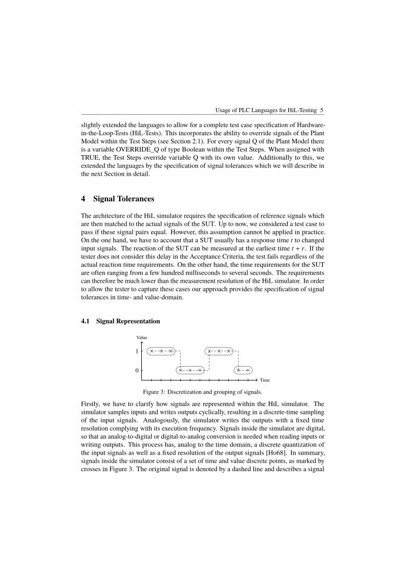
Usage of PLC Languages for HiL-Testing 5
slightly extended the languages to allow for a complete test case specification of Hardware-in-the-Loop-Tests (HiL-Tests). This incorporates the ability to override signals of the PlantModel within the Test Steps (see Section 2.1). For every signal Q of the Plant Model thereis a variable OVERRIDE_Q of type Boolean within the Test Steps. When assigned withTRUE, the Test Steps override variable Q with its own value. Additionally to this, weextended the languages by the specification of signal tolerances which we will describe inthe next Section in detail.
4 Signal Tolerances
The architecture of the HiL simulator requires the specification of reference signals whichare then matched to the actual signals of the SUT. Up to now, we considered a test case topass if these signal pairs equal. However, this assumption cannot be applied in practice.On the one hand, we have to account that a SUT usually has a response time t to changedinput signals. The reaction of the SUT can be measured at the earliest time t + r. If thetester does not consider this delay in the Acceptance Criteria, the test fails regardless of theactual reaction time requirements. On the other hand, the time requirements for the SUTare often ranging from a few hundred milliseconds to several seconds. The requirementscan therefore be much lower than the measurement resolution of the HiL simulator. In orderto allow the tester to capture these cases our approach provides the specification of signaltolerances in time- and value-domain.
4.1 Signal Representation
Value
Time
0
1
Figure 3: Discretization and grouping of signals.
Firstly, we have to clarify how signals are represented within the HiL simulator. Thesimulator samples inputs and writes outputs cyclically, resulting in a discrete-time samplingof the input signals. Analogously, the simulator writes the outputs with a fixed timeresolution complying with its execution frequency. Signals inside the simulator are digital,so that an analog-to-digital or digital-to-analog conversion is needed when reading inputs orwriting outputs. This process has, analog to the time domain, a discrete quantization ofthe input signals as well as a fixed resolution of the output signals [Ho68]. In summary,signals inside the simulator consist of a set of time and value discrete points, as marked bycrosses in Figure 3. The original signal is denoted by a dashed line and describes a signal
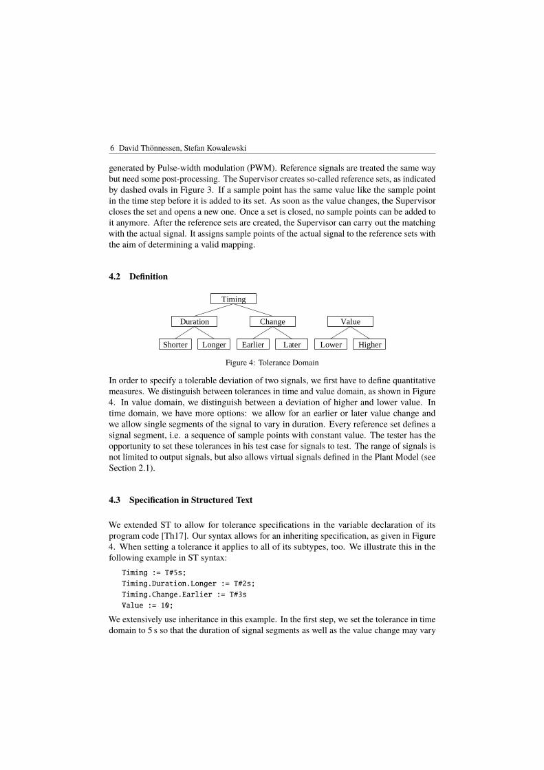
6 David Thönnessen, Stefan Kowalewski
generated by Pulse-width modulation (PWM). Reference signals are treated the same waybut need some post-processing. The Supervisor creates so-called reference sets, as indicatedby dashed ovals in Figure 3. If a sample point has the same value like the sample pointin the time step before it is added to its set. As soon as the value changes, the Supervisorcloses the set and opens a new one. Once a set is closed, no sample points can be added toit anymore. After the reference sets are created, the Supervisor can carry out the matchingwith the actual signal. It assigns sample points of the actual signal to the reference sets withthe aim of determining a valid mapping.
4.2 Definition
Shorter Longer Earlier Later
Duration Change
Lower Higher
Value
Timing
Figure 4: Tolerance Domain
In order to specify a tolerable deviation of two signals, we first have to define quantitativemeasures. We distinguish between tolerances in time and value domain, as shown in Figure4. In value domain, we distinguish between a deviation of higher and lower value. Intime domain, we have more options: we allow for an earlier or later value change andwe allow single segments of the signal to vary in duration. Every reference set defines asignal segment, i.e. a sequence of sample points with constant value. The tester has theopportunity to set these tolerances in his test case for signals to test. The range of signals isnot limited to output signals, but also allows virtual signals defined in the Plant Model (seeSection 2.1).
4.3 Specification in Structured Text
We extended ST to allow for tolerance specifications in the variable declaration of itsprogram code [Th17]. Our syntax allows for an inheriting specification, as given in Figure4. When setting a tolerance it applies to all of its subtypes, too. We illustrate this in thefollowing example in ST syntax:Timing := T#5s;
Timing.Duration.Longer := T#2s;
Timing.Change.Earlier := T#3s
Value := 10;
We extensively use inheritance in this example. In the first step, we set the tolerance in timedomain to 5 s so that the duration of signal segments as well as the value change may vary
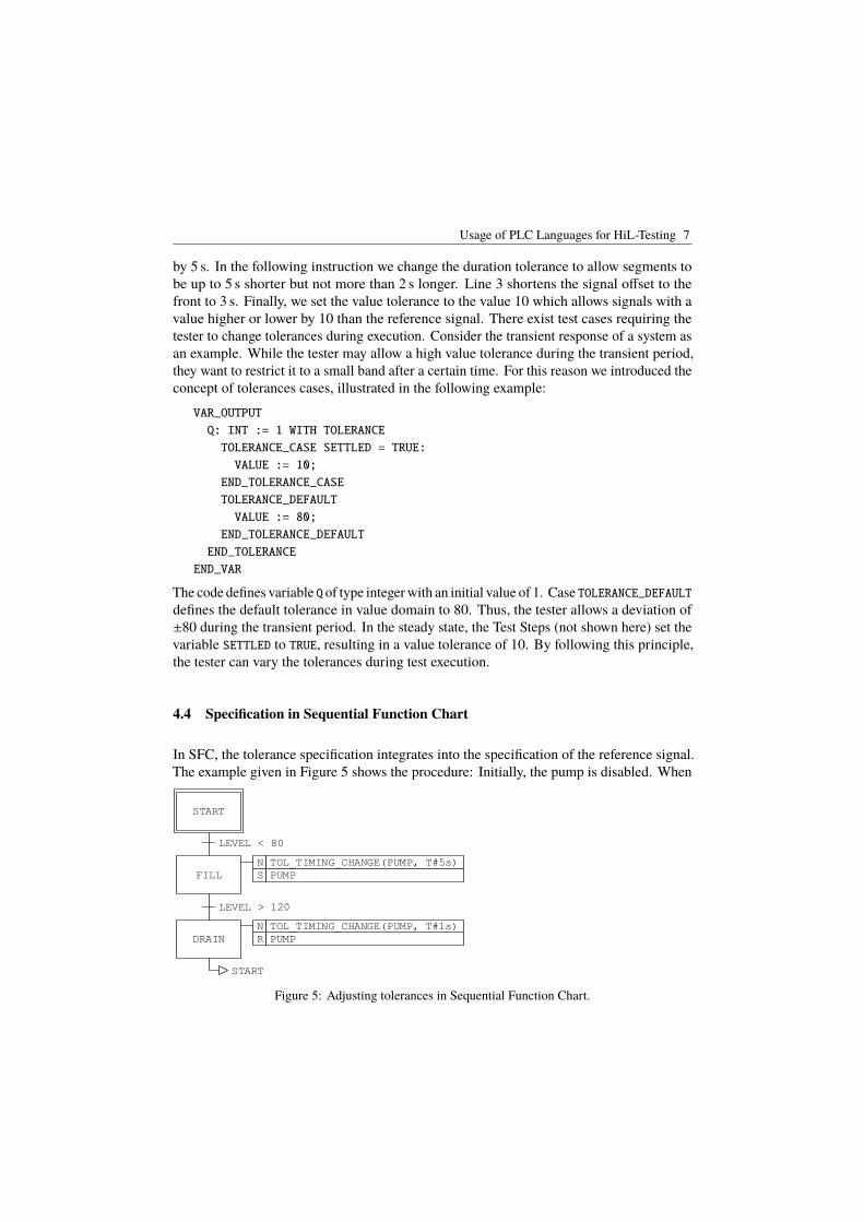
Usage of PLC Languages for HiL-Testing 7
by 5 s. In the following instruction we change the duration tolerance to allow segments tobe up to 5 s shorter but not more than 2 s longer. Line 3 shortens the signal offset to thefront to 3 s. Finally, we set the value tolerance to the value 10 which allows signals with avalue higher or lower by 10 than the reference signal. There exist test cases requiring thetester to change tolerances during execution. Consider the transient response of a system asan example. While the tester may allow a high value tolerance during the transient period,they want to restrict it to a small band after a certain time. For this reason we introduced theconcept of tolerances cases, illustrated in the following example:VAR_OUTPUT
Q: INT := 1 WITH TOLERANCE
TOLERANCE_CASE SETTLED = TRUE:
VALUE := 10;
END_TOLERANCE_CASE
TOLERANCE_DEFAULT
VALUE := 80;
END_TOLERANCE_DEFAULT
END_TOLERANCE
END_VAR
The code defines variable Q of type integer with an initial value of 1. Case TOLERANCE_DEFAULTdefines the default tolerance in value domain to 80. Thus, the tester allows a deviation of±80 during the transient period. In the steady state, the Test Steps (not shown here) set thevariable SETTLED to TRUE, resulting in a value tolerance of 10. By following this principle,the tester can vary the tolerances during test execution.
4.4 Specification in Sequential Function Chart
In SFC, the tolerance specification integrates into the specification of the reference signal.The example given in Figure 5 shows the procedure: Initially, the pump is disabled. When
START
FILL
DRAIN
LEVEL < 80
LEVEL > 120
START
S PUMP
N TOL_TIMING_CHANGE(PUMP, T#5s)
R PUMP
N TOL_TIMING_CHANGE(PUMP, T#1s)
Figure 5: Adjusting tolerances in Sequential Function Chart.

8 David Thönnessen, Stefan Kowalewski
the level falls below 80, the tester wants the pump to activate with a time tolerance of ±5 s.The tolerance is applied just when the execution switches to state FILL. If the level exceeds120, the tester wants the pump to deactivate with a time tolerance of ±1 s set by the DRAINstate. This specification aims to imitate the state- and action-based implementation of SFCsby an action-based specification of signal tolerances.
5 Application
L1 L2
S
B
Figure 6: Conveyor belt as a sample application.
This section will discuss the application of the presented approach using a simple, exemplaryplant. The plant is shown in Figure 6 and consists of a belt B, a punch S, and two lightbarriers L1 and L2. As soon as a workpiece interrupts L1, the belt starts to run and stops assoon as it interrupts L2. The punch then operates the workpiece and the belt carries it away.We will now show the implementation of the modules Plant Model and Test Steps in ST andAcceptance Criteria in SFC. The specification of signal tolerances is done in ST. Pleaseconsider the shown implementation to be minimal and to make simplified assumptions inorder to focus on the understanding of the concept. The Plant Model is implemented asfollows:IF B THEN
POSITION := POSITION + 1;
END_IF
IF POSITION > 5 THEN
L1 := FALSE;
END_IF
L2 := (POSITION >= 50 && POSITION <= 55);
The position is initialized with 0 and stored as an internal variable. When the belt moves,the position is increased in every cycle by 1. As soon as the position exceeds 5, L1 isdefined to be non-interrupted because the workpiece is not in its measuring field anymore.L2 is interrupted just when the position is in the range of 50 to 55. This implementationcovers the sensor data of the SUT and thus is an adequate plant model. The next step is toimplement the Test Steps. In this example, the SUT is stimulated by placing a workpiece onthe belt, i.e. interrupting L1. Consequently, the implementation consists of one instructionthat sets the sensor value of L1 to TRUE. The last step is the implementation of Acceptance
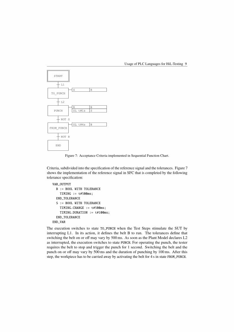
Usage of PLC Languages for HiL-Testing 9
START
TO_PUNCH
PUNCH
L1
L2
S B
R B
SL t#1s S
FROM_PUNCH
NOT S
SL t#4s B
END
NOT B
Figure 7: Acceptance Criteria implemented in Sequential Function Chart.
Criteria, subdivided into the specification of the reference signal and the tolerances. Figure 7shows the implementation of the reference signal in SFC that is completed by the followingtolerance specification:VAR_OUTPUT
B := BOOL WITH TOLERANCE
TIMING := t#500ms;
END_TOLERANCE
S := BOOL WITH TOLERANCE
TIMING.CHANGE := t#500ms;
TIMING.DURATION := t#100ms;
END_TOLERANCE
END_VAR
The execution switches to state TO_PUNCH when the Test Steps stimulate the SUT byinterrupting L1. In its action, it defines the belt B to run. The tolerances define thatswitching the belt on or off may vary by 500 ms. As soon as the Plant Model declares L2as interrupted, the execution switches to state PUNCH. For operating the punch, the testerrequires the belt to stop and trigger the punch for 1 second. Switching the belt and thepunch on or off may vary by 500 ms and the duration of punching by 100 ms. After thisstep, the workpiece has to be carried away by activating the belt for 4 s in state FROM_PUNCH.
10 David Thönnessen, Stefan Kowalewski
6 Conclusion
The presented approach allows for the implementation of test cases by slightly extended PLCprogramming languages (see Section 3 and 4.2). Made possible by the modular achitecture,i.e. the division into Plant Model, Test Steps, and Acceptance Criteria, the tester can adaptparts of the test case efficiently. We aim for an agile testing process by this modularity andthe closeness to PLC programming languages. In future work, we will present and evaluatean implementation of the presented concept, based on the Soft-PLC Twistturn [OKK14].
References[Be11] Berger, H: Automatisieren mit STEP 7 in AWL und SCL: Speicherprogrammierbare
Steuerungen SIMATIC S7-300/400. Publicis Publ., 2011.
[BtHVH14] Bauernhansl, Thomas; ten Hompel, Michael; Vogel-Heuser, Birgit: Industry 4.0 inProduktion, Automatisierung und Logistik. Werkstattstechnik, 103(March):648, 2014.
[Gu07] Gu, Fangming; Harrison, William S.; Tilbury, Dawn M.; Yuan, Chengyin: Hardware-in-the-loop for manufacturing automation control: Current status and identified needs.In: Proceedings of the 3rd IEEE International Conference on Automation Science andEngineering, IEEE CASE 2007. pp. 1105–1110, 2007.
[Ho68] Hoeschele, David F: Analog-to-digital/digital-to-analog conversion techniques. 1968.
[IE11] IEC 26262-4: Road vehicles - Functional safety - Part 4: Product development at thesystem level. IEC, 2011.
[IE13] IEC 61131-3: Programmable controllers - Part 3: Programming languages. IEC, 2013.
[Na16] National Instruments: Hardware-in-the-Loop (HIL) Test System Architectures. 2016.
[OKK14] Obster, Mathias; Kalkov, Igor; Kowalewski, Stefan: Development and execution of PLCprograms on real-time capable mobile devices. In: Emerging Technology and FactoryAutomation (ETFA). IEEE, pp. 1–8, 2014.
[Th17] Thönnessen, D.; Reinker, N.; Rakel, S.; Kowalewski, S.: A Concept for PLC Hardware-in-the-loop Testing Using an Extension of Structured Text. In: Emerging Technologyand Factory Automation (ETFA). IEEE, pp. 1–8, 2017.
[TK18] Thönnessen, D.; Kowalewski, S.: Agiles Testen von cyber-physischen Produktionssyste-men. atp edition, 2018. Manuscript submitted for publication.
[Wi17] Wiechowski, Norbert; Rambow, Thomas; Busch, Rainer; Kugler, Alexander; Hansen,Norman; Kowalewski, Stefan: Arttest – a New Test Environment for Model-BasedSoftware Development. In: SAE Technical Paper. SAE International, pp. 1–11, 2017.
[Zh07] Zhang, Peng; Luk, Wai Shing; Song, Yu; Tong, Jiarong; Tang, Pushan; Zeng, Xuan:WCOMP: Waveform Comparison Tool for Mixed-Signal Validation Regression inMemory Design. Proceedings of the Asia and South Pacific Design AutomationConference, ASP-DAC, pp. 209–214, 2007.
cba
Michaela Huhn, Hardi Hungar, Matthias Riebisch, Sebastian Voss (Hrsg.):Modellbasierte Entwicklung Eingebetteter Systeme,
Lecture Notes in Informatics (LNI), Gesellschaft für Informatik, Bonn 2018 1
Finding Inconsistencies in Design Models and Requirementsby Applying the SMARDT Process
Stefan Kriebel1, Evgeny Kusmenko2, Bernhard Rumpe2, Michael von Wenckstern2
Abstract: The development of safety critical systems requires a highly automated integratedmethodology supporting the design, verification and validation of the overall product. Such amethodology maintains the consistency and correctness of all artifacts at all development stagesideally incorporating requirements changes into the corresponding models, tests, and code. Thispaper shows how the SMARDT process uses formalized SysML diagrams to identify inconsistenciesin architectural designs and requirements. An adaptive light system serves as illustrative runningexample.
1 Introduction
Safety critical software systems undergo a complex development process before they areintroduced onto the market. The manufacturers are obliged to make their systems ISO26262compliant and to guarantee the correctness of their implementation. Usually such systemsbecome very large and have to fulfill hundreds of intertwined requirements developed bydifferent teams. Therefore, an urgent need for automated means of consistency checking ofrequirement specifications identifying errors in early design stages has been arising.
At BMW, one of Germany’s largest automotive companies, the new SMARDT process triesto tackle this problem. One of its goals is to ensure artifact consistency for the differentphases of the development process by using model-based software engineering (MBSE),particularly formalized SysML diagrams.
This paper shows how the SMARDT process uses formalized SysML diagrams to identifyinconsistencies in design decisions and requirements. Thereby, we focus on artifacts ofthe logical layer of the SMARDT process and demonstrate the idea on the requirementspecification of a real-world Adaptive Light System (ALS).
Section 3 recaps the main ideas of the SMARDT process. Section 4 shows how Component& Connector (C&C) views reveal structural design inconsistencies derived from different1 BMW Group, Munich, Germany; [email protected] RWTH Aachen University, Software Engineering, Ahornstraße 55, 52074 Aachen, Germany;kusmenko,rumpe,[email protected]
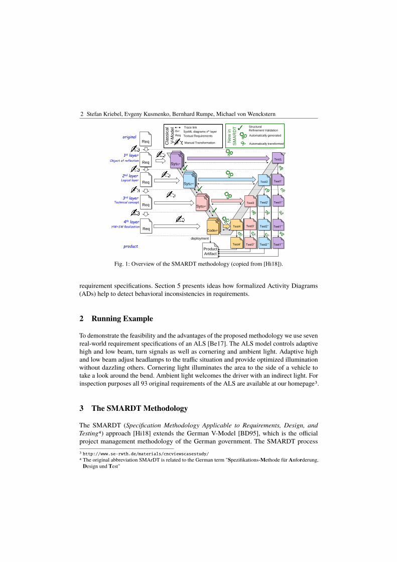
2 Stefan Kriebel, Evgeny Kusmenko, Bernhard Rumpe, Michael von Wenckstern
D
1st layer
2nd layer
Req
Req
DSys1st
DDSys2nd
Object of reflection
Logical layer
3rd layer
Req DDSys3rd
4th layer
Req DDCode4th
Technical concept
HW+SW Realization
Reqoriginal
Structural
Refinement ValidationDxth SysML diagrams xth layer
Req Textual Requirements
Trace link
Manual Transformation
Automatically generated
Product
Artifact
deployment
Test1
Test1’
Test1’’
Test1’’’
Test1’’’
Test2
Test2’
Test2’’
Test2’’’
Test3
Test3’
Test3’’
Test4
Test4’product
Automatically transformed
New
in
SM
AR
DT
Cla
ssic
al
V-M
ode
l
Fig. 1: Overview of the SMARDT methodology (copied from [Hi18]).
requirement specifications. Section 5 presents ideas how formalized Activity Diagrams(ADs) help to detect behavioral inconsistencies in requirements.
2 Running Example
To demonstrate the feasibility and the advantages of the proposed methodology we use sevenreal-world requirement specifications of an ALS [Be17]. The ALS model controls adaptivehigh and low beam, turn signals as well as cornering and ambient light. Adaptive highand low beam adjust headlamps to the traffic situation and provide optimized illuminationwithout dazzling others. Cornering light illuminates the area to the side of a vehicle totake a look around the bend. Ambient light welcomes the driver with an indirect light. Forinspection purposes all 93 original requirements of the ALS are available at our homepage3.
3 The SMARDT Methodology
The SMARDT (Specification Methodology Applicable to Requirements, Design, andTesting4) approach [Hi18] extends the German V-Model [BD95], which is the officialproject management methodology of the German government. The SMARDT process
3 http://www.se-rwth.de/materials/cncviewscasestudy/
4 The original abbreviation SMArDT is related to the German term "Spezifikations-Methode für Anforderung,Design und Test"

Finding Inconsistencies in Design Models and Requirements by Applying the SMARDT Process 3
delivers reliable specification methodologies by introducing formalized SysML diagrams[OM15] with a well-defined semantics [HR04] to specify the functionality of automotivesystems. This allows to automatically ensure a permanent consistency between all abstractionlayers of the V-Model. This task can become particularly tedious if maintained by hand inagile development processes as those are mostly iterative, incremental, and evolutionary[Be01]. New validations enabled by SMARDT process are: (1) backward compatibilitychecks [Ru15, Ri16, Be16, Ku18] for software maintenance and evolution between differentdiagram versions of the same layer, (2) refinement checks [Ru96, HRvW17] betweendiagrams of different layers allowing to detect specification inconsistencies betweendifferent layers, as well as (3) advanced structural or extra-functional property [Ma16]checks on SysML diagrams using OCL [Ma17].
The key principles of SMARDT for a formal specification of requirements, design, andtesting of system engineering artifacts according to ISO 26262 are illustrated in Figure 1.The methodology is structured in four layers: (1) The object of reflection layer contains a firstdescription of the object under consideration and shows its boundaries from a customer’spoint of view. (2) The logical layer containing functional specifications without details oftheir technical realizations. (3) The technical concept, e.g. C code or Simulink models,belongs to the third layer. Finally, the fourth layer represents the software and hardwareartifacts present in the system’s implementation.
In SMARDT consistency between different layers is ensured by verification and model-basedtesting of the final product against the requirements of all layers. More specifically, SMARDTenables structural verification as explained in Section 4 between each layer indicated bythe green check marks in Figure 1. Furthermore, SMARDT enables a systematic and fullyautomatic derivation of test cases for each layer as discussed in [Hi18] and illustrated on theright side of Figure 1. The previous SMARDT paper [Hi18] showed how this methodologyis applied to develop a self-driving racing vehicle; its main focus was the use of formalizedADs enriched by OCL constraints for automated test case derivation. In contrast, this paperfocuses on detecting structural and behavioral inconsistencies between different artifacts inthe logical layer of the SMARDT process.
4 Architecture Specification using Views
Embedded software systems are often created in Simulink as C&C models describingfunctional, logical or software architectures [TMD09] in terms of components executingcomputations and connectors effecting component interaction via typed and directed ports.An advantage of this approach is that complex components such as ALS can be hierarchicallydecomposed into other smaller components to be developed by different teams. Interactionbetween components occur only via connectors. SysML and Modelica are two other famousrepresentatives for C&C modeling languages.

4 Stefan Kriebel, Evgeny Kusmenko, Bernhard Rumpe, Michael von Wenckstern
ALS
Flashing
HeadLight
FlLeft
FlRight
FlLeft
FlRight
LightSwitchCLeft
CRight
ALeft
ARight
AmbientLightBrightness
CorneringLight
Brightness
Key
ALeft
ARight
FlLeft
FlRight
Speed
LightSwitch
Voltage
CLeft
CRight
BlinkerLever
Hazard
Key
Speed
Voltage
component
component name
port
port name
junction
connector
C&C Model
Fig. 2: Very simple example C&C model for ALS.
C&C views, as presented in [MRR13], are developed to focus on important view points(excerpts) of large C&C models without being required to model all the other (for theview point unimportant) information. For example a view can only show how a componentis decomposed into subcomponents without showing any ports and connections of thesubcomponents. The main aim of C&C views concept is to have many but therefore small,precise and good-readable view points of one large C&C model. For this reason C&Cviews introduce four major abstractions: hierarchy, connectivity, data flow, and interfacesof C&C models. The hierarchy of components in C&C views is not necessarily direct(intermediate components may be skipped); abstract connectors can cross-cut componentboundaries and they can also connect components directly (if the concrete connected port isnot important for this view); abstract effectors describe data flow abstracting over chains ofcomponents and connectors, and C&C views do not require complete interfaces with portnames, types and array sizes. Intuitively, a C&C model satisfies a C&C view iff all elementsand relations shown by the view have a satisfying concretization in the model. The formaldefinitions of C&C model, C&C view, and their satisfaction are available in [MRR13] andfrom supporting materials website of paper [Be17].
C&C View Verification and Witnesses for Tracing Figure 2 shows the example C&Cmodel of an adaptive light system (ALS). This simplified model controls the flash LEDsfor turning as well as the left and right light bulbs for cornering and ambient lights. TheALS consists of the two subcomponents Flashing and HeadLight. Component HeadLight ishierarchically decomposed into two further components: CorneringLight, and AmbientLight.The C&C view ALS1 shown in Figure 3 describes the CorneringLight component illuminatingon intersections the road where the driver wants to turn into. Thus, the input port BlinkerLever

Finding Inconsistencies in Design Models and Requirements by Applying the SMARDT Process 5
ALSCorneringLight
Blinker
Lever CLeft
CRight
view ALS1
abstract
connector
abstract
effector
ALS
Flashing Ambient
LightFlLeft
ALeft
view ALS2
Fig. 3: Two C&C views ALS1(top) and ALS2 (bottom)
ALS
Flashing HeadLight
FlLeftCLeft
CRight
CorneringLightFlLeft
CLeft
CRight
BlinkerLever
witness ALS1s
ALS Flashing
HeadLight
FlLeft FlLeft
CLeft
CRight
AmbientLight
CorneringLight
ALeft
FlLeft CLeft
CRight
witness ALS2n
C&C Model is missing an effector from the component Flashing
to the component AmbientLight (from port FlLeft to port Aleft)
Fig. 4: Witness for satisfaction ALS1s (top) and witness for non-satisfaction ALS2n (bottom)
of the ALS component has effect (modeled by an abstract effector) to at least one inputport of the CorneringLight component. The calculated light values (CLeft, and CRight) ofthe CorneringLight component are passed directly (without being modified anymore) tothe output ports of the ALS component (modeled by two abstract connectors). The C&Cview ALS2 is about the relation between the Flasing and the AmbientLight component. Itspecifies that the FlLeft (flashing left) output of components Flashing effects the ambientleft light (port ALeft of component AmbientLight); e.g. brighter left ambient light when theleft parking mode is activated. The model ALS satisfies the view ALS1.
C&C view verification, as presented in [MRR14], gets as input a C&C model and a C&Cview. Besides a Boolean answer whether the C&C model satisfies the C&C view, theverification algorithm produces a local minimal satisfaction or one or more local non-satisfaction witnesses. As an example, a witness for satisfaction ALS1s is shown in Figure 4and demonstrates how the C&C model satisfies ALS1. The SMARDT approach uses thegenerated witnesses to automatically generate traceability information between SysMLartifacts of layer 2 (C&C views) against the large SysML model of layer 3 (C&C models).The witness is itself a well-formed model. The witness contains all view’s components (hereALS, and CornerningLight) as well as their parent components to show the complete hierarchybetween two components specified in the view. Therefore, the witness contains also theHeadLight component. The positive satisfaction witness also contains all ports correspondingto a view, therefore the witness contains BlinkerLever port of ALS as well as CLeft, andCRight ports of CorneringLight. Additionally the witness contains all model connectors and
6 Stefan Kriebel, Evgeny Kusmenko, Bernhard Rumpe, Michael von Wenckstern
all data-flow paths. The abstract connector from CorneringLight (port CLeft) to ALS (portunknown) introduces the following elements in the witness: (1) port CLeft of componentHeadLight; (2) connector of ports CLeft from component CorneringLight to componentHeadLight; and (3) connector of ports CLeft from component HeadLight to component ALS. Forthe abstract effector from ALS (port BlinkerLever) to CorneringLight the following elementsin the chain serve as witness: (1) component Flashing; (2) ports BlinkerLever and FlLeft ofFlashing; (3) connector of ports BlinkerLever from ALS to Flashing; (4) connector of portsFlLeft from Flashing to HeadLight; and (5) connector of ports FlLeft from HeadLight toCorneringLight.
The model ALS does not satisfy the view ALS2. Every negative non-satisfaction witnesscontains a minimal subset of the C&C model and a natural-language text, which togetherexplain the reason for non-satisfaction. These witnesses are divided into five categories:MissingComponent, HierarchyMismatch, InterfaceMismatch, MissingConnection, Missing-Effector (see [MRR14]). A witness for non-satisfaction ALS2n (case MissingEffector) isshown in Figure 4. It shows all outgoing connector-effector chains starting at port FlLeftof component Flashing as well as the abstract effector’s target port, AmbientLight’s ALeft,which is not reachable. Removing the effectors in the view ALS2 would cause the model tosatisfy this modified view even though Flashing and AmbientLight are direct siblings in theC&C view and are not direct siblings in the C&C model; C&C views allow to abstract awaythe intermediate component HeadLight.
Identifying Design Inconsistencies with C&C Views The previous paragraphs showedhow C&C views verification can be used to check structural consistencies and how togenerate tracing witnesses between artifacts of layer B (view models) against artifactof layer C (concrete logical C&C models). This part focuses on identifying structuraldesign inconsistencies between different artifact models of layer B. Figure 5 shows tworequirements about the cornering light. Since the last requirement AL-139 is a safety featurefor armored vehicles, a special team is responsible for it. Thus, the architectural designs (viewAL-122, and view AL-139) for the two requirements are developed by two different teams. Thetop design shows the CorneringLight with two modes (subcomponents Cornering_Active,Cornering_Deactive, and MultiSwitch), whereby the mode Cornering_Deactive is selected ifthe voltage is too low. In the bottom design model the min block in combination with theSwitch one deactivates indirectly the cornering light by propagating 0% as light value toOvervoltageProtection’s input ports when the DarknessSwitch port has the value true. C&Cview synthesis [MRR13] is the process in deriving one valid C&C model which satisfiesall given C&C views. The first part of this algorithm checks whether views contain designcontradictions. When all views as in our example are positive views (only expressing whatshould be present; and do not contain negations such as component A should not containport B), then the contradiction check can be done in polynomial time and scales very wellto many hundreds views.
The contradiction check for the both views view AL-122 and view AL-139 would result in an
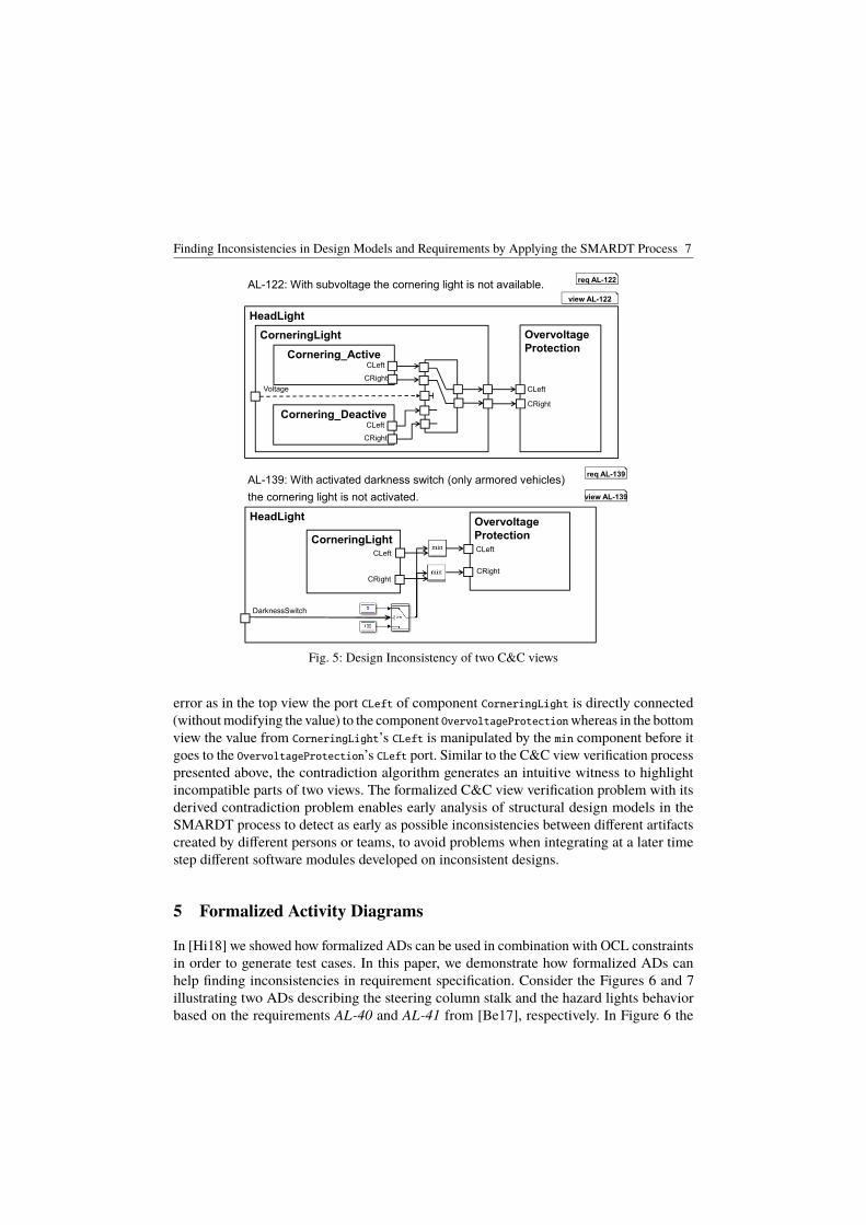
Finding Inconsistencies in Design Models and Requirements by Applying the SMARDT Process 7
AL-122: With subvoltage the cornering light is not available. req AL-122
view AL-122
HeadLight
CorneringLight
Voltage
Cornering_ActiveCLeft
CRight
Cornering_DeactiveCLeft
CRight
Overvoltage
Protection
CLeft
CRight
AL-139: With activated darkness switch (only armored vehicles)
the cornering light is not activated.
req AL-139
HeadLight
CorneringLight
DarknessSwitch
Overvoltage
Protection
view AL-139
CLeft
CRight
CLeft
CRight
Fig. 5: Design Inconsistency of two C&C views
error as in the top view the port CLeft of component CorneringLight is directly connected(without modifying the value) to the component OvervoltageProtectionwhereas in the bottomview the value from CorneringLight’s CLeft is manipulated by the min component before itgoes to the OvervoltageProtection’s CLeft port. Similar to the C&C view verification processpresented above, the contradiction algorithm generates an intuitive witness to highlightincompatible parts of two views. The formalized C&C view verification problem with itsderived contradiction problem enables early analysis of structural design models in theSMARDT process to detect as early as possible inconsistencies between different artifactscreated by different persons or teams, to avoid problems when integrating at a later timestep different software modules developed on inconsistent designs.
5 Formalized Activity Diagrams
In [Hi18] we showed how formalized ADs can be used in combination with OCL constraintsin order to generate test cases. In this paper, we demonstrate how formalized ADs canhelp finding inconsistencies in requirement specification. Consider the Figures 6 and 7illustrating two ADs describing the steering column stalk and the hazard lights behaviorbased on the requirements AL-40 and AL-41 from [Be17], respectively. In Figure 6 the

8 Stefan Kriebel, Evgeny Kusmenko, Bernhard Rumpe, Michael von Wenckstern
Set Left Lights
Steering Column
Stalk (SCS)Read SteeringColumn Stalk
Left Lights
DirectionIndicatorLeft
[else] [SCS == ]
AL-40 Direction indicator (left): When the steering column stalk is moved into the
position blinking (left) all left direction indicators (rear left, exterior mirrors left, front
left) start blinking synchronously with an on/off ration of 1:1.
LeftLights = 1: 1Otherwise, thevalue of LEFT isunderspecified
req AL-40
AD AL-40
Fig. 6: Activity diagram for AL-40 describing the steering column stick behavior.
Read HazardLight Switch
Right Lights
HazardLights
[else] [HLS == ]
AL-41 Hazard lights: As long as the hazard light switch is pressed, all direction indicator lamps blink
synchronously. If the ignition key is inside the lock, the on/off ration is 1:1. Otherwise, the on/off ratio
is 1:2.
Ignition Key (IK)
Hazard Light
Switch (HLS)
[IK == ] [IK == ]
Read IgnitionKey
Set Left Lights Left Lights
Set Right Lights
LeftLights = 1: 2 LeftLights = 1: 1
RightLights = 1: 1RighLights = 1: 2
req AL-41
AD AL-41
Fig. 7: Activity diagram for AL-41 describing the emergency lights behavior.
model would receive the state of the steering column stalk through the corresponding inputport. If the position of the steering column stalk is set to left, the left lights of the car areset to the blinking mode with an on/off ratio of 1:1, denoted as BLINKING1:1. This value iswritten to the output port of the AD. The else branch is underspecified, i.e., nothing is saidabout the output for the cases if the steering column stalk is set to right or to straight. Note,that this is in accordance with the underlying requirement.
In the AD of Figure 7, the hazard light switch is read in order to decide whether to turn
Finding Inconsistencies in Design Models and Requirements by Applying the SMARDT Process 9
the lights on or not. However, to determine the concrete blinking mode, the position ofthe ignition key is required. If the key is inserted, the 1:1 blinking mode is activated,otherwise the 1:2 mode is used to save battery power. The else branch is underspecifiedagain. Note, that according to the requirement the same physical lights are used for hazardblinking as for direction indication. This leads to a contradiction which becomes obviousin the two ADs: if the key is not inside the lock and the hazard light switch is pressed,according to AL-41, the vehicle’s indicators lamps should blink with a ratio of 1:2. Nowimagine that at the same time the steering column stalk is set to blinking (left). Accordingto AL-40 the blinking ratio of the left direction indicators should be 1:1. Considering thata faster blinking drains the battery in a shorter amount of time, this specification errormight even become critical for human lives in cases of emergency. The error is discoveredautomatically by creating a table mapping the three input signals to the specified lamp lightmodes and filling it with all specified combinations. For Figure 6 we would obtain onesingle combination, namely: (SCS = LEFT,HLS = DC, IK = DC) → (Le f tLights =BLINKING1 : 1, RightLights = DC) where DC stands for "don’t care". Figure 7produces two combinations one of which is (SCS = DC,HLS = ON, IK = OFF) →(Le f tLights = BLINKING1 : 2, RightLights = BLINKING1 : 2). Expanding the DCfields to all possible values reveals that the specification requires two contradictory outputsfor the same input.
6 Conclusion
In this paper we discussed the need for automated consistency checks for requirementand design artifacts of safety critical systems. Therefore, we developed a methodologysupporting the SMARDT process - a formalized version of the widely used V-Model - byidentifying wrong or contradicting requirements at early development stages using C&Cviews and activity diagrams. The methodology was demonstrated on a real-world ALSrequirement specification. Using the proposed concepts we were able to detect structural andbehavioral inconsistencies on the logical layer of the SMARDT process, i.e., long beforethe actual implementation would be created. Future work comprises analysis of furtherformalized diagrams and their respective combinations as well as detailed case studies ofthe complete SMARDT process and the proposed tooling.
Acknowledgements This research was supported by a Grant from the GIF, the German-Israeli Foundation for Scientific Researchand Development, and by the Grant SPP1835 from DFG, the German Research Foundation.
References[BD95] Bröhl, Adolf-Peter; Dröschel, Wolfgang: Das V-Modell. München, Wien: Oldenburg-
Verlag, 1995.
[Be01] Beck, Kent; Beedle, Mike; Van Bennekum, Arie; Cockburn, Alistair; Cunningham, Ward;Fowler, Martin; Grenning, James; Highsmith, Jim; Hunt, Andrew; Jeffries, Ron et al.:Manifesto for agile software development. 2001.
10 Stefan Kriebel, Evgeny Kusmenko, Bernhard Rumpe, Michael von Wenckstern
[Be16] Bertram, Vincent; Roth, Alexander; Rumpe, Bernhard; von Wenckstern, Michael: Ex-tendable Toolchain for Automatic Compatibility Checks. In: OCL’16. 2016.
[Be17] Bertram, Vincent; Maoz, Shahar; Ringert, Jan Oliver; Rumpe, Bernhard; von Wenckstern,Michael: Case Study on Structural Views for Component and Connector Models. In:MODELS. 2017.
[Hi18] Hillemacher, Steffen; Kriebel, Stefan; Kusmenko, Evgeny; Lorang, Mike; Rumpe, Bern-hard; Sema, Albi; Strobl, Georg; von Wenckstern, Michael: Model-Based Developmentof Self-Adaptive Autonomous Vehicles using the SMARDT Methodology. In: MODEL-SWARD’18. 2018.
[HR04] Harel, David; Rumpe, Bernhard: Meaningful Modeling: What’s the Semantics of ”Se-mantics”? IEEE Computer, 37(10), 2004.
[HRvW17] Heithoff, Malte; Rumpe, Bernhard; von Wenckstern, Michael: Anforderungsverikationvon Komponenten- und Konnektormodellen am Beispiel Autonom Fahrender Autos. GISoftwaretechnik-Trends, 37(2), 2017.
[Ku18] Kusmenko, Evgeny; Shumeiko, Igor; Rumpe, Bernhard; von Wenckstern, Michael: FastSimulation Preorder Algorithm. In: MODELSWARD. 2018.
[Ma16] Maoz, Shahar; Ringert, Jan Oliver; Rumpe, Bernhard; Wenckstern, Michael von: Con-sistent Extra-Functional Properties Tagging for Component and Connector Models. In:ModComp. 2016.
[Ma17] Maoz, Shahar; Mehlan, Ferdinand; Ringert, Jan Oliver; Rumpe, Bernhard; von Wenck-stern, Michael: OCL Framework to Verify Extra-Functional Properties in Componentand Connector Models. In: ModComp. 2017.
[MRR13] Maoz, Shahar; Ringert, Jan Oliver; Rumpe, Bernhard: Synthesis of component andconnector models from crosscutting structural views. In: FSE. 2013.
[MRR14] Maoz, Shahar; Ringert, Jan Oliver; Rumpe, Bernhard: Verifying component and connectormodels against crosscutting structural views. In: ICSE. 2014.
[OM15] OMG: OMG Systems Modeling Language (OMG SysML). Technical Report Version1.4, 2015.
[Ri16] Richenhagen, Johannes; Rumpe, Bernhard; Schloßer, Axel; Schulze, Christoph; Thissen,Kevin; von Wenckstern, Michael: Test-driven Semantical Similarity Analysis for SoftwareProduct Line Extraction. In: SPLC. 2016.
[Ru96] Rumpe, Bernhard: Formale Methodik des Entwurfs verteilter objektorientierter Systeme.Herbert Utz Verlag Wissenschaft, 1996.
[Ru15] Rumpe, Bernhard; Schulze, Christoph; von Wenckstern, Michael; Ringert, Jan Oliver;Manhart, Peter: Behavioral Compatibility of Simulink Models for Product Line Mainte-nance and Evolution. In: SPLC. 2015.
[TMD09] Taylor, Richard N.; Medvidovic, Nenad; Dashofy, Eric: Software Architecture: Founda-tions, Theory, and Practice. Wiley, 2009.

cba
Herausgeber et al. (Hrsg.): Modellbasierte Entwicklung eingebetteter Systeme MBEES2018,Lecture Notes in Informatics (LNI), Gesellschaft für Informatik, Bonn 2018 1
Applying DSE for Solving the Deployment Problem inIndustry 4.0
Tarik Terzimehic1, Sebastian Voss1, Monika Wenger1, Vincent Aravantinos1
Abstract:
The fourth industrial revolution requires a dynamically reconfigurable control software, in order tocope with frequent product and production process changes of manufacturing systems. To dynamicallyreconfigure control software, we have to calculate valid or optimal deployment configurations.Previous research applies Design Space Exploration (DSE) techniques embedded into model-baseddesign methodologies for solving this deployment problem. However, current research either aims atdomains other than industrial automation or applies simple and, for real-life problems, not applicableconstraints and objectives. Thus, the deployment of software components to hardware components isstill an exhausting and manual task. In this work, we take first steps towards automatically optimizeddeployment of industrial automation systems. We propose the concept of DSE for solving thedeployment problems of IEC 61499 based control software applications. In order to reduce theexploration space, we identify the industry 4.0 specific constraints and objectives. Furthermore, weextend the IEC 61499 system and application models’ descriptions by proposing relevant hardware andsoftware annotations. The presented concept could be used in conjunction with different optimizationand satisfiability solving algorithms, such as SMT or linear programming.
Keywords: Design Space Exploration; Model-based Development; Deployment; IEC 61499;Industry 4.0
1 Introduction
Frequent product and production process’ changes in current manufacturing systems makepredetermined processes and system configurations infeasible [Sp16]. Thus, dynamicreconfigurability and flexibility of control software are named as key prerequisites towardsthe fourth industrial revolution, referred to as industry 4.0 [Wa16]. In order to reconfigurethe control software consisting of software components (SWCs), a proper configuration hasto be generated. The configuration can comprise a particular deployment (or mapping) ofSWCs, i.e. deployable software units, to hardware components (HWCs), e.g. ProgrammableLogic Controllers (PLCs), further referred to as solely deployment. A valid deploymentsatisfies certain constraints, such as maximal hardware cost, energy consumption etc. SinceIndustry 4.0 requires an optimal manufacturing process [Bu17], we may strive to generate a1 fortiss GmbH, Model-based systems engineering, Guerickestraße 25, Munich, Germany, terzimehic,voss,
wenger,[email protected]
2 Tarik Terzimehic, Sebastian Voss, Monika Wenger, Vincent Aravantinos
deployment that is optimal with respect to the given objectives (e.g. calculate a deploymentconfiguration that leads to the minimal energy consumption). Additionally, a scheduler(e.g. the execution order of the SWCs or temporal order of communication [BV13]) can begenerated as part of the configuration.
Due to the increased complexity of current current manufacturing systems (i.e. the growingnumber of SWCs and HWCs, their properties and specifications), it is difficult to manuallyfind a valid or an optimal deployment configuration [Ed17]. When manual design decisionsare difficult due to a large exploration space, design space exploration (DSE) techniquesare applied. DSE defines the process of finding a solution (or set of solutions) within aconstrained solution space [Sc10].
DSE can be used in conjunction with model-based development (MbD), which provides asystem abstraction with suitable models. Different models describe the system from differentperspectives. For example, a logical or software model describes the functionality of thesystem, whereas a technical or hardware model describes the platform/hardware specificaspects of the system. Thereby the system’s functionality can be developed independentlyfrom the hardware specification, which is an important advantage of this approach especiallyfor complex systems [Ar15].
Numerous research studies apply DSE techniques embedded into MbD methodologies withthe aim to find appropriate configurations, i.e. valid or optimal deployments and schedulers[Ed17, ZKC16, AB17]. For example, [Ed17] uses the Satisfiability modulo theories (SMT)solver to explore the design space. However, it does not fit industrial control software, as(1) it applies automotive-specific constraints, objectives and annotations and (2) the usedmodel-based tool is based on the FOCUS theory [BS01], which is not common in industrialcontrol software and therefore probably unfamiliar for process engineers and technicians.
Common industrial control software applications are based on the IEC 61131-3 standardfor PLCs, developed with the main goal to unify the way of programming PLCs. Moreover,the standard introduced function blocks (FBs) to improve the quality, modularity, andreusability of control applications. However, the usage of global variables links the FBsvia hidden interfaces. The IEC 61499 standard, which represents an extension of theIEC 61131-3 standard, also uses FB as the main element of function encapsulation, butcompletely forbids the usage of global data. Therefore, the FBs are decoupled from itsenvironment and can be used and tested separately, thereby greatly increasing the reusabilityand reconfigurability of IEC 61499-based control applications. Furthermore, the IEC 61499defines basic reconfiguration services, which provide the possibility to reconfigure theapplication during runtime [Le11].
In [SJC14], a SMT solver is applied to generate valid reconfigurations of IEC 61499-basedcontrol systems. This work describes the control software architectures and the high-levelrequirements with logical formulae. The logical formulae are used as input for a SMTsolver. The SMT solver calculates deployment configurations for deploying FBs multiple
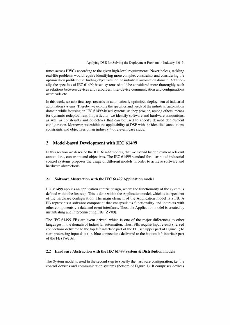
Applying DSE for Solving the Deployment Problem in Industry 4.0 3
times across HWCs according to the given high-level requirements. Nevertheless, tacklingreal-life problems would require identifying more complex constraints and considering theoptimization problem, i.e. finding objectives for the industrial automation domain. Addition-ally, the specifics of IEC 61499-based systems should be considered more thoroughly, suchas relations between devices and resources, inter-device communication and configurationsoverheads etc.
In this work, we take first steps towards an automatically optimized deployment of industrialautomation systems. Thereby, we explore the specifics and needs of the industrial automationdomain while focusing on IEC 61499-based systems, as they provide, among others, meansfor dynamic redeployment. In particular, we identify software and hardware annotations,as well as constraints and objectives that can be used to specify desired deploymentconfiguration. Moreover, we exhibit the applicability of DSE with the identified annotations,constraints and objectives on an industry 4.0 relevant case study.
2 Model-based Development with IEC 61499
In this section we describe the IEC 61499 models, that we extend by deployment relevantannotations, constraint and objectives. The IEC 61499 standard for distributed industrialcontrol systems proposes the usage of different models in order to achieve software andhardware abstractions.
2.1 Software Abstraction with the IEC 61499 Application model
IEC 61499 applies an application centric design, where the functionality of the system isdefined within the first step. This is done within the Application model, which is independentof the hardware configuration. The main element of the Application model is a FB. AFB represents a software component that encapsulates functionality and interacts withother components via data and event interfaces. Thus, the Application model is created byinstantiating and interconnecting FBs [ZV09].
The IEC 61499 FBs are event driven, which is one of the major differences to otherlanguages in the domain of industrial automation. Thus, FBs require input events (i.e. redconnections delivered to the top left interface part of the FB, see upper part of Figure 1) tostart processing input data (i.e. blue connections delivered to the bottom left interface partof the FB) [We16].
2.2 Hardware Abstraction with the IEC 61499 System & Distribution models
The System model is used in the second step to specify the hardware configuration, i.e. thecontrol devices and communication systems (bottom of Figure 1). It comprises devices
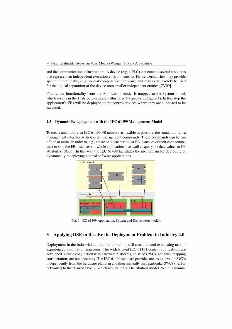
4 Tarik Terzimehic, Sebastian Voss, Monika Wenger, Vincent Aravantinos
and the communication infrastructure. A device (e.g. a PLC) can contain several resourcesthat represent an independent execution environments for FB networks. They may providespecific functionality (e.g. special computation hardware), but may as well solely be usedfor the logical separation of the device onto smaller independent entities [ZV09].
Finally, the functionality from the Application model is mapped to the System model,which results in the Distribution model (illustrated by arrows in Figure 1). In this step theapplication’s FBs will be deployed to the control devices where they are supposed to beexecuted.
2.3 Dynamic Redeployment with the IEC 61499 Management Model
To create and modify an IEC 61499 FB network as flexible as possible, the standard offers amanagement interface with special management commands. These commands can be runoffline or online in order to, e.g., create or delete particular FB instances or their connections,start or stop the FB instances (or whole applications), as well as query the data values or FBattributes [SC05]. In this way the IEC 61499 facilitates the mechanism for deploying ordynamically redeploying control software applications.
Fig. 1: IEC 61499 Application, System and Distribution models
3 Applying DSE to Resolve the Deployment Problem in Industry 4.0
Deployment in the industrial automation domain is still a manual and exhausting task ofexperienced automation engineers. The widely used IEC 61131 control applications aredeveloped in close conjunction with hardware platforms, i.e. used HWCs, and thus, mappingconsiderations are not necessary. The IEC 61499 standard provides means to develop SWCsindependently from the hardware platform and then manually map particular SWCs (i.e. FBnetworks) to the desired HWCs, which results in the Distribution model. While a manual
Applying DSE for Solving the Deployment Problem in Industry 4.0 5
Tab. 1: Constraints, objectives and annotations for IEC 61499-based systems
Constraint Objective SW Annotation HW AnnotationCostlimit costs of HWCs Min. costs - CostNumber of HWCslimit number of used HWCs
Min. numberof used HWCs - -
HW capabilitiesallocate SWCs to required HWCs -
Required HWcapabilities
Available HWcapabilities
RTE capabilitiesallocate SWCs to compatible RTEs -
Required FBtypes
AvailableFB library
Parallel executionexecute SWCs parallel - Parallel SWCs
Max. numberof resources
Functional couplinggroup coupled SWCs
Max. cohesion,min. coupling Coupled SWCs -
Memoryprevent memory exceeding
Min. memoryusage pro HWC Memory size
Availablememory
SILallocate SWCs to reliable HWCs Min. total SIL Safety level Safety levelRedundancyallocate SWCs to several HWCs - Number of copies -
deployment is acceptable for a small number of components, constraints and objectives,systems that are more complex require this process to be optimally automated. In order todo so, an automation engineer has to be able to specify the deployment problem.
We specify the deployment problem through constraints that limit the set of possibleallocations due to different attributes. Moreover, we can express optimization demands,i.e. objectives, that optimize a limited set of solutions towards certain directions. Table 1presents the constraints, objectives and corresponding annotations, applicable for IEC 61499based systems.
Cost constraint and objective The economical aspect is crucial for the construction andoperation of automation plants. For that purpose we require a hardware cost annotation,which is also often applied in the automotive domain [ZKC16]. For example, the automationengineer can specify the cost of HWCs (e.g. PLCs) while modeling the hardware architecture(e.g. within System model of IEC 61499 architecture). Subsequently the engineer can specifythe constraint, so that the total cost of whole applied hardware infrastructure does not exceeda certain maximal value. We can also strive to minimize the whole cost, in which case wedefine an optimization objective.
Number of devices constraint and objective Due to economical (i.e. cost reduction)or/and technical aspects (i.e. easier maintenance, decreased latency as result of increased
6 Tarik Terzimehic, Sebastian Voss, Monika Wenger, Vincent Aravantinos
intra-node communication etc.) we can limit or minimize the number of used HWCs, whilecalculating valid or optimal deployment configurations, respectively.
HW capabilities constraint Some SWCs or applications require certain hardware capa-bilities, such as special computation hardware, access to particular sensors or actuators,communication interfaces etc. Thus, an engineer should be able to either (1) manuallyallocate particular SWCs to particular HWCs and calculate the mapping of remainingcomponents according to other specified constraints and/or objectives (as it is done in[Ed17]), or (2) specify the required and offered capabilities within the Application andSystem models, respectively. For example, a SWC (i.e. FB network in the IEC 61499-basedsystems) requires access and a HWC (i.e. device in the IEC 61499-based systems) providesaccess to the light barrier sensor within a conveyor. By applying this constraint, we assuredeployment of the SWC to the required HWC.
RTE capabilities constraint If we want to dynamically (re)deploy applications, we need toconsider the run-time environment (RTE) running on the HWC. Questionable is whetherthe RTE of the HWC we want to deploy the SWC(s) to, contains all necessary FB types,since only available FB types can be instantiated. Thus, it should be possible to describethe capabilities of the RTE, i.e. to specify its FB library. The required FB types arealready specified within the Application model. Hence, only HWCs whose RTEs contain allnecessary FB types can be considered as deployment targets.
Parallel execution constraint A device (i.e. HWC) in a System model can containresources, which can be regarded as independent execution containers for FB applications.Resources provide a logical separation of the device onto smaller independent entities. Bydeploying applications onto multiple resources, we can achieve a quasi parallel execution2.However, a device cannot contain an arbitrary number of resources without jeopardizing itscomputational and memory performances. Thus, the annotation of the maximal number ofresources within one device should be possible. On the other hand, the Application modelshould provide mechanisms to denote parallel FB networks, i.e. the parts of the applicationsthat are supposed to run concurrently.
Functional coupling constraint and objective Similarly, we may want to couple someapplications, so that they are executing within the same device, or even within the sameresource. Motivation for that could be the lower latency between applications, i.e. increasingthe intra-device and decreasing inter-device communications. Thus, we can define thefunctional coupling constraint by selecting the FB networks supposed to be executedwithin the same device. Alternatively, we can specify an objective, in order to maximizecohesion and minimize coupling, i.e. maximize the intra-device and minimize inter-devicecommunications.
Memory constraint and objective The annotation of hardware’s memory capacity, soft-ware’s memory size and the constraint, that prohibits exceeding the hardware memory
2 quasi parallel since resources can only be processed in parallel if they run on different cores of the CPU
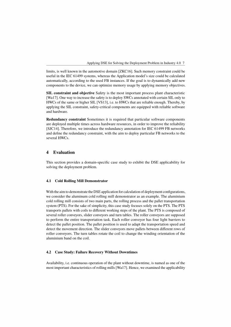
Applying DSE for Solving the Deployment Problem in Industry 4.0 7
limits, is well known in the automotive domain [ZKC16]. Such memory constraint could beuseful in the IEC 61499 systems, whereas the Application model’s size could be calculatedautomatically, according to the used FB instances. If the goal is to dynamically add newcomponents to the device, we can optimize memory usage by applying memory objectives.
SIL constraint and objective Safety is the most important process plant characteristic[Wa17]. One way to increase the safety is to deploy SWCs annotated with certain SIL only toHWCs of the same or higher SIL [VS13], i.e. to HWCs that are reliable enough. Thereby, byapplying the SIL constraint, safety-critical components are equipped with reliable softwareand hardware.
Redundancy constraint Sometimes it is required that particular software componentsare deployed multiple times across hardware resources, in order to improve the reliability[SJC14]. Therefore, we introduce the redundancy annotation for IEC 61499 FB networksand define the redundancy constraint, with the aim to deploy particular FB networks to theseveral HWCs.
4 Evaluation
This section provides a domain-specific case study to exhibit the DSE applicability forsolving the deployment problem.
4.1 Cold Rolling Mill Demonstrator
With the aim to demonstrate the DSE application for calculation of deployment configurations,we consider the aluminum cold rolling mill demonstrator as an example. The aluminiumcold rolling mill consists of two main parts, the rolling process and the pallet transportationsystem (PTS). For the sake of simplicity, this case study focuses solely on the PTS. The PTStransports pallets with coils to different working steps of the plant. The PTS is composed ofseveral roller conveyors, slider conveyors and turn tables. The roller conveyors are supposedto perform the entire transportation task. Each roller conveyor has four light barriers todetect the pallet position. The pallet position is used to adapt the transportation speed anddetect the movement direction. The slider conveyors move pallets between different rows ofroller conveyors. The turn tables rotate the coil to change the winding orientation of thealuminium band on the coil.
4.2 Case Study: Failure Recovery Without Downtimes
Availability, i.e. continuous operation of the plant without downtime, is named as one of themost important characteristics of rolling mills [Wa17]. Hence, we examined the applicability
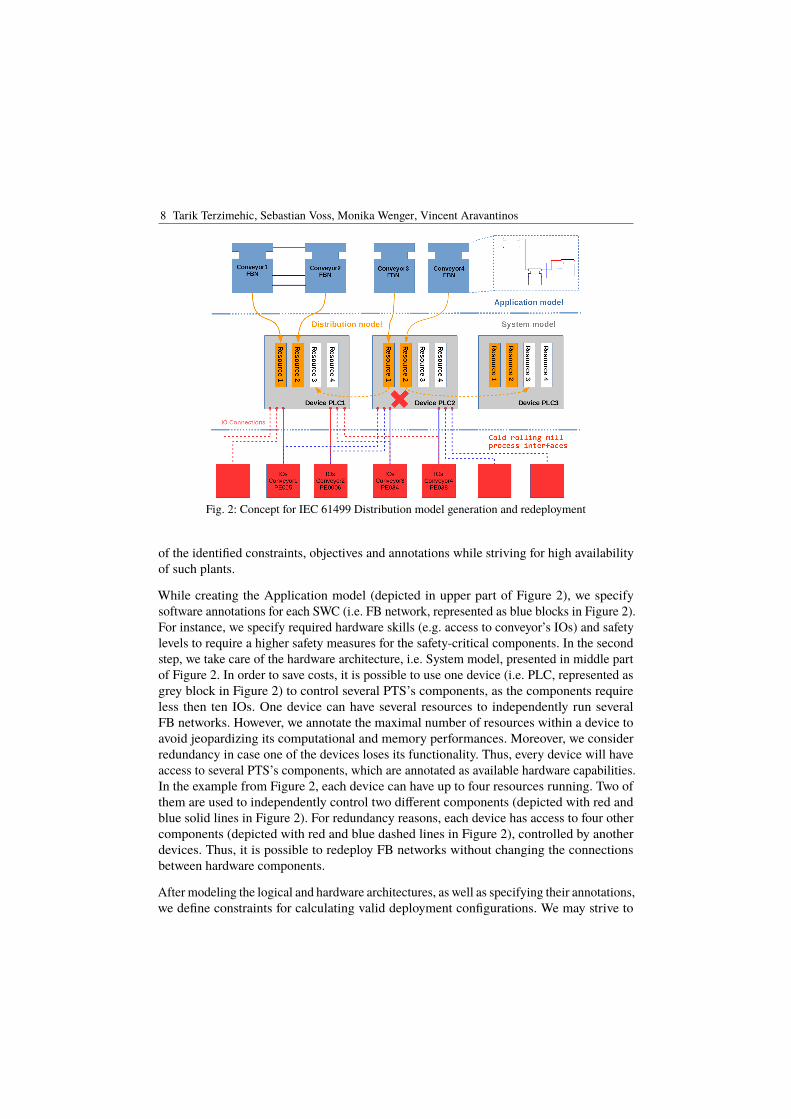
8 Tarik Terzimehic, Sebastian Voss, Monika Wenger, Vincent Aravantinos
Fig. 2: Concept for IEC 61499 Distribution model generation and redeployment
of the identified constraints, objectives and annotations while striving for high availabilityof such plants.
While creating the Application model (depicted in upper part of Figure 2), we specifysoftware annotations for each SWC (i.e. FB network, represented as blue blocks in Figure 2).For instance, we specify required hardware skills (e.g. access to conveyor’s IOs) and safetylevels to require a higher safety measures for the safety-critical components. In the secondstep, we take care of the hardware architecture, i.e. System model, presented in middle partof Figure 2. In order to save costs, it is possible to use one device (i.e. PLC, represented asgrey block in Figure 2) to control several PTS’s components, as the components requireless then ten IOs. One device can have several resources to independently run severalFB networks. However, we annotate the maximal number of resources within a device toavoid jeopardizing its computational and memory performances. Moreover, we considerredundancy in case one of the devices loses its functionality. Thus, every device will haveaccess to several PTS’s components, which are annotated as available hardware capabilities.In the example from Figure 2, each device can have up to four resources running. Two ofthem are used to independently control two different components (depicted with red andblue solid lines in Figure 2). For redundancy reasons, each device has access to four othercomponents (depicted with red and blue dashed lines in Figure 2), controlled by anotherdevices. Thus, it is possible to redeploy FB networks without changing the connectionsbetween hardware components.
After modeling the logical and hardware architectures, as well as specifying their annotations,we define constraints for calculating valid deployment configurations. We may strive to

Applying DSE for Solving the Deployment Problem in Industry 4.0 9
deploy SWCs to the HWCs with required SIL, HW and RTE capabilities, while limiting thenumber of running resources within each HWC. When the desired constraints are specified,a solver (e.g. SMT solver) is launched to generate a set of valid deployment configurations.To increase the quality of the solution, a quality attribute such as HWC load is defined(i.e. minimize number of SWCs on each HWC). Thus we select valid configuration forwhich HWCs are less stressed and then perform the deployment according to the selectedconfiguration.
During runtime we monitor the state of the components. In case a certain HWC losses itsfunctionality or becomes overloaded (e.g. PLC2), we select another valid configurationfrom the set of the calculated configurations. Here we apply the second best configurationaccording to the quality attribute (i.e. HWC load), since the first one is invalidated due tothe PLC2 failure. Alternatively, we can strive for a configuration that leads to less HWCs’changes. After configuration selection, we redeploy necessary SWCs using IEC 61499reconfiguration services.
This way, we achieve a failure recovery without downtimes, as we apply another validconfiguration without a time exhaustive recalculation. The recalculation of the configurationsconsidering actual system status can be performed afterwards, during the system runtime.
5 Conclusion & Future Work
By analyzing the specifics of the industrial automation domain, more precisely IEC 61499based systems, we identified constraints, objectives and annotations applicable for deploy-ment problem definition. Thereby, we took first steps towards an automatically optimizeddeployment of industrial automation systems. The domain-specific case study exhibits theapplicability of the DSE approach in conjunction with IEC 61499 models in an industry 4.0relevant scenario, namely failure recovery without downtime.
Within the next step, we intend to implement and validate the proposed concept by usingEclipse 4diac, an open source, IEC 61499-compliant engineering framework [SZV08]. Weplan to extend the framework by the identified annotations, constraints and objectives, aswell as the deployment synthesis model. Moreover, we will continue identifying relevantconstraints, objectives and annotations.
References[AB17] Alexander Diewald, Sebastian Voss; Barner, Simon: A Lightweight Design Space Exploration
And Optimization Language. In: CEUR Workshop Proceedings. 2017.
[Ar15] Aravantinos, Vincent; Voss, Sebastian; Teufl, Sabine; Hölzl, Florian; Schätz, Bernhard:AutoFOCUS 3: Tooling concepts for seamless, model-based development of embeddedsystems. In: CEUR Workshop Proceedings. 2015.
10 Tarik Terzimehic, Sebastian Voss, Monika Wenger, Vincent Aravantinos
[BS01] Broy, Manfred; Stolen, Ketil: Specification And Development Of Interactive Systems FocusOn Streams Interfaces And Refinement. Springer, 2001.
[Bu17] Bundesministerium für Wirtschaft und Energie (BMWi): Beziehungen zwischen I4.0-Komponenten – Verbundkomponenten und intelligente Produktion. Technical report, 2017.
[BV13] Becker, Klaus; Voss, Sebastian: Towards Dynamic Deployment Calculation for ExtensibleSystems using SMT-Solvers. In: 1st Open EIT ICT Labs Workshop on CPS Eng. 2013.
[Ed17] Eder, Johannes; Zverlov, Sergey; Voss, Sebastian; Khalil, Maged; Ipatiov, Alexandru: BringingDSE to life: exploring the design space of an industrial automotive use case. In: 20th Int.Conf. on MdE Lang. and Syst. (MODELS). 2017.
[Le11] Lepuschitz, Wilfried; Zoitl, Alois; Vallée, Mathieu; Merdan, Munir: Toward self-reconfiguration of manufacturing systems using automation agents. IEEE Trans. on Systems,Man and Cybernetics, 2011.
[SC05] SC65B, IEC: , IEC 61499-1 Function Blocks for Industrial Process Measurement and ControlSystems. Part 4: Rules for compliance profiles, 2005. Geneva.
[Sc10] Schätz, Bernhard; Schätz, Bernhard; Hölzl, Florian; Lundkvist, Torbjörn: Design-SpaceExploration through Constraint-Based Model-Transformation. In: 17th IEEE Int. Conf. andWorkshops on Eng. of Comp. Based Syst. 2010.
[SJC14] Sinha, Roopak; Johnson, Kenneth; Calinescu, Radu: A scalable approach for re-configuringevolving industrial control systems. In: 19th IEEE Int. Conf. on Emerging Technologies andFactory Automation. 2014.
[Sp16] Spindler, M.; Aicher, T.; Vogel-Heuser, B.; Günthner, W.: Efficient Control Software Designfor Automated Material Handling Systems Based on a Two-Layer Architecture. In: Int. Conf.on Adv. Log. and Trans. 2016.
[SZV08] Strasser, Thomas; Zoitl, Alois; Valentini, Antonio: Framework for Distributed IndustrialAutomation and Control (4DIAC). In: 6th IEEE Int. Conf. on Ind. Info. 2008.
[VS13] Voss, Sebastian; Schatz, Bernhard: Deployment and scheduling synthesis for mixed-criticalshared-memory applications. In: Proceedings of the Int. Symp. and Workshop on Eng. ofComp. Based Syst. 2013.
[Wa16] Wang, Shiyong; Wan, Jiafu; Li, Di; Zhang, Chunhua: Implementing Smart Factory ofIndustrie 4 . 0 : An Outlook. Int. Journal of Dist. Sensor Net., 2016, 2016.
[Wa17] Wagner, Constantin; Epple, Ulrich; Metzul, Alfred; Debus, Kai; Treivous, Vadim; Tarnow,Matthias; Helle, Christoph: Requirements for the Next Generation Automation Solution ofRolling Mills. In: 43rd Annual Conf. of the IEEE Ind. Elec. Society. 2017.
[We16] Wenger, Monika; Zoitl, Alois; Blech, Jan Olaf; Peake, Ian; Fernando, Lasith: Cloud basedmonitoring of timed events for industrial automation. In: Proceedings of the Int. Conf. onParallel and Dist. Syst. 2016.
[ZKC16] Zverlov, Sergey; Khalil, Maged; Chaudhary, Mayank: Pareto-efficient deployment synthesisfor safety-critical applications in seamless model-based development. In: Proceedings of the8th European Congress on Embedded Real Time Software and Systems. 2016.
[ZV09] Zoitl, Alois; Vyatkin, Valeriy: IEC 61499 architecture for distributed automation: The "glasshalf full"view. IEEE Industrial Electronics Magazine, 2009.
cba
Herausgeber et al. (Hrsg.): MBEES,Lecture Notes in Informatics (LNI), Gesellschaft für Informatik, Bonn 2017 1
Exploration of hardware topologies and complexity reduction
Johannes Eder1
Abstract: This paper shall give an overview over a dissertation project in the area of design spaceexploration for distributed, embedded systems. As the engineering of distributed embedded systems isgetting more and more complex due to increasingly sophisticated functionalities demanding more andmore powerful hardware, automation is required in order cope with this rising complexity. Using amodel based systems engineering approach enables design space exploration methods which providesuch automations, formalizing the problem in order to be solvable e.g. by SMT solvers. However, dueto the complexity of the systems, those problems cannot be efficiently solved. It is thus furthermorerequired to provide mechanisms to reduce the complexity. This can be achieved by using domainspecific knowledge of the systems and apply machine learning approaches to learn about the problemand thus provide means to reduce its complexity.
1 Introduction - System engineering and its complexity
The design of distributed, embedded systems is characterized by an ever-growing complexityof those systems. This is caused by an increasing set of functionality, as well as an increasein complexity in the underlying hardware architecture and topology. Considering e.g. theautomotive domain, the introduction of more and more autonomous functions not onlyincreases the amount of software in the vehicles but also demands hardware capable ofexecuting this software.
Using a classical systems engineering approach like the V-Model, as proposed e.g. inthe ISO 26262 for functional safety of automotive vehicles, the development process isdivided into the product development on software and hardware level and the integration ofthose two parts. In the following the rising complexity of not only software, hardware andintegration but also of the aspect of variability will be outlined which demands automationsupport in the development process of distributed embedded systems.
Software complexity The main driver of the complexity of software for distributedembedded systems are increasingly sophisticated functionalities e.g. in the automotivedomain, due to the trend towards more and more autonomous vehicles resulting in arising number of driver assistance and autonomous functions. In 2007, e.g., a premiumcar contained already 270 user functions resulting in 2500 ’atomic’ software functions1 fortiss GmbH, MbSE, Guerickestrasse 25, 80805 Munich, [email protected]
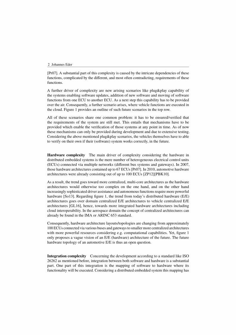
2 Johannes Eder
[Pr07]. A substantial part of this complexity is caused by the intricate dependencies of thesefunctions, complicated by the different, and most often contradicting, requirements of thesefunctions.
A further driver of complexity are new arising scenarios like plug&play capability ofthe systems enabling software updates, addition of new software and moving of softwarefunctions from one ECU to another ECU. As a next step this capability has to be providedover the air. Consequently, a further scenario arises, where vehicle functions are executed inthe cloud. Figure 1 provides an outline of such future scenarios in the top row.
All of these scenarios share one common problem: it has to be ensured/verified thatthe requirements of the system are still met. This entails that mechanisms have to beprovided which enable the verification of those systems at any point in time. As of nowthese mechanisms can only be provided during development and due to extensive testing.Considering the above mentioned plug&play scenarios, the vehicles themselves have to ableto verify on their own if their (software) system works correctly, in the future.
Hardware complexity The main driver of complexity considering the hardware indistributed embedded systems is the mere number of heterogeneous electrical control units(ECUs) connected via multiple networks (different bus systems and gateways). In 2007,those hardware architectures contained up to 67 ECUs [Pr07]. In 2010, automotive hardwarearchitectures were already consisting out of up to 100 ECUs [ZP12][PBK10].
As a result, the trend goes toward more centralized, multi-core architectures as the hardwarearchitectures would otherwise too complex on the one hand, and on the other handincreasingly sophisticated driver assistance and autonomous functions require more powerfulhardware [So13]. Regarding figure 1, the trend from today’s distributed hardware (E/E)architectures goes over domain centralized E/E architectures to vehicle centralized E/Earchitectures [GL16], hence, towards more integrated hardware architectures includingcloud interoperability. In the aerospace domain the concept of centralized architectures canalready be found in the IMA or ARINC 653 standard.
Consequently, hardware architecture layouts/topologies are changing from approximately100 ECUs connected via various buses and gateways to smaller more centralized architectureswith more powerful resources considering e.g. computational capabilities. Yet, figure 1only proposes a vague vision of an E/E (hardware) architecture of the future. The futurehardware topology of an automotive E/E is thus an open question.
Integration complexity Concerning the development according to a standard like ISO26262 as mentioned before, integration between both software and hardware is a substantialpart. One part of this integration is the mapping of software to hardware where itsfunctionality will be executed. Considering a distributed embedded system this mapping has
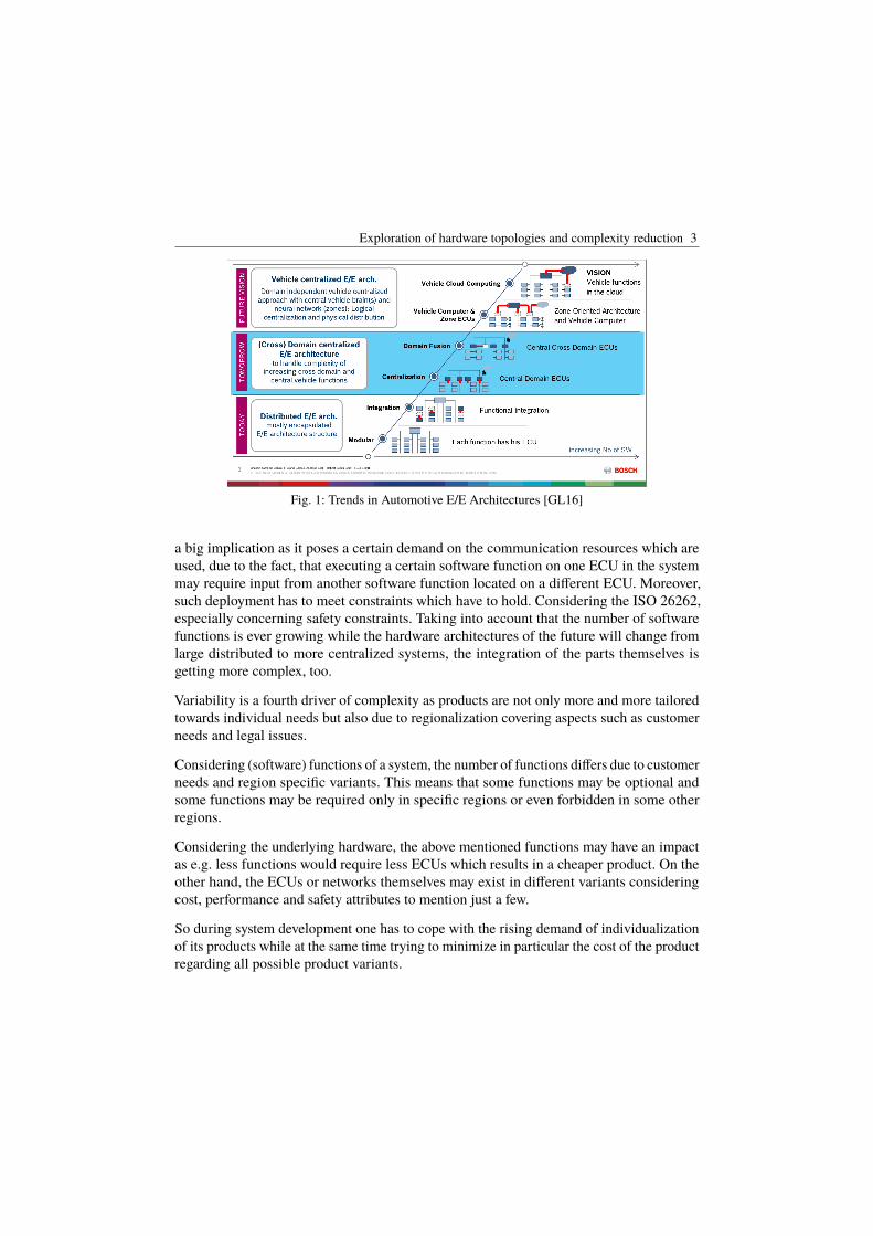
Exploration of hardware topologies and complexity reduction 3
Fig. 1: Trends in Automotive E/E Architectures [GL16]
a big implication as it poses a certain demand on the communication resources which areused, due to the fact, that executing a certain software function on one ECU in the systemmay require input from another software function located on a different ECU. Moreover,such deployment has to meet constraints which have to hold. Considering the ISO 26262,especially concerning safety constraints. Taking into account that the number of softwarefunctions is ever growing while the hardware architectures of the future will change fromlarge distributed to more centralized systems, the integration of the parts themselves isgetting more complex, too.
Variability is a fourth driver of complexity as products are not only more and more tailoredtowards individual needs but also due to regionalization covering aspects such as customerneeds and legal issues.
Considering (software) functions of a system, the number of functions differs due to customerneeds and region specific variants. This means that some functions may be optional andsome functions may be required only in specific regions or even forbidden in some otherregions.
Considering the underlying hardware, the above mentioned functions may have an impactas e.g. less functions would require less ECUs which results in a cheaper product. On theother hand, the ECUs or networks themselves may exist in different variants consideringcost, performance and safety attributes to mention just a few.
So during system development one has to cope with the rising demand of individualizationof its products while at the same time trying to minimize in particular the cost of the productregarding all possible product variants.
4 Johannes Eder
2 Problem statement
In order to effectively manage the ever increasing complexity in the design of embeddedsystems, development processes in general, and model-based approaches in particular,support the development. They are assuming an idealized (component-based) model ofcomputation, abstracting away from implementation issues like interference aspects of theexecution platform resulting from shared computation or memory resources.
However, as requested by the ISO 26262, those simplifying abstractions must be met bydevelopment steps which ensure that the assumptions behind these abstraction are notviolated by the properties of the implementation platform. For instance, during SW-/HW-integration, platform mechanisms must avoid an overload in bus communication, such thatmessages do not arrive to late or even get lost. The distribution of software across differentexecution platforms is thus highly affecting different aspects of such an integration. Due tothe complexity of the design alternatives, automated support for selecting optimal solutionsis needed. A question whose answer is more and more demanded in industry consideringsystems engineering is hence also one of the most challenging ones:
"What is a good or even optimized/optimal system design and how to findit - automatically?".
The definition of what a "goodör even öptimalßystem design looks like, requires a detailed(formalized) understanding of the different parts of the system which are concerned, as wellas the requirements, namely the constraints and optimization objectives, which limit the setof possible designs. It is furthermore highly dependent on the various aspects of systemdesign. In particular, considering a (optimal) synthesis of a technical HW platform, one hasto integrate knowledge from various parts, to answer this question:
1. Software parts (components) of the system which represent its functionality, poseresource demands w.r.t. to the application considering e.g. a certain computing poweror communication.
2. Hardware parts (components) which actually provide computing and communicationcapabilities and are composed according to certain hardware layout rules.
3. The deployment which assigns software parts to hardware parts where their functio-nality can be realized.
4. Variability of software parts and hardware parts leading to different deployments andthus to different variants of system designs.
The (automatic) identification of valid designs, in particular valid hardware designs, is amanually unsolvable task, especially considering not only the rising complexity within the
Exploration of hardware topologies and complexity reduction 5
development of software and hardware, but also considering the different variants in thedevelopment especially of the hardware part. A sensor for example may exist in differentvariants differing in properties such as cost or performance but also in the set of possibleinterfaces enabling a connection to differing communication units (buses). A decision infavor of a certain sensor is thus affecting the whole hardware topology as its interfacelimits the set of possible communication resources which can be used. Striving for anoptimal hardware topology is furthermore closely intertwined with the deployment of SWcomponents to HW components due to the fact that software is demanding a certain amountof computational resources (memory, performance,..) in order to be executed as well ascommunication resources enabling exchange of information. So, the problem of finding anoptimal hardware topology together with a deployment, while at the same time handlingvariability in order to come up with an optimal system design, demands automation.
3 Contribution
The envisioned contribution of this thesis is two-folded. Firstly, we want to propose asynthesis methodology capable of synthesizing a distributed embedded systems architecturewhile at the same time considering variability aspects of this architecture. Secondly, wewant to provide a classification of complexity for this domain specific scenario in order tobe able to increase the efficiency of the proposed methodology.
3.1 Hardware Topology Synthesis
Considering the future vision of E/E architectures depicted in figure 1, the envisionedcontribution of this thesis goes even one step further such that the E/E architecture is notfixed at all. Using the 150% model approach - which is common in variability research - wewant to propose an approach that synthesizes a E/E architecture topology. This entails thatgiven 150% of all possible elements of an E/E architecture and a (100%) component-basednetwork of all SW-components (functions) of the system under development, the goal of thisthesis is not only to choose 100% of the needed E/E elements but also to set up a respectivetopology of these elements.
At the same time, all requirements for this system have to be considered. On the onehand, constraints which limit the set of possible solutions. Firstly, those constraints maybe deployment specific such that the limit they set of possible deployments of certain SW-Components to certain ECUs due to e.g. safety requirements. Secondly, those constraintsmay be topology specific, such that they restrict the set of possible connections in theE/E architecture, e.g. the connection of ECUs to communication devices such as buses orgateways. On the other hand, optimization objectives have to considered, which optimizethe topology into certain directions such as the overall cost of the E/E architecture or thenumber of ECUs.
6 Johannes Eder
Specifically, this entails the following sub-contributions.
1. Dedicated models of the technical (E/E) architecture, covering variability as well astopological aspects.
2. A respective language to formalize the synthesis problem. A first step has been donein [Ed17] covering the deployment aspects of the methodology. The language has tobe extended in order to able to express topological and variability aspects.
3. A transformation of the language into the SMTLIB2 language standard in order to beable to solve problems expressed in this language with state-of-the-art SMT solvers.
4. A dedicated exploration methodology providing an overall concept for such a synthesis.(Categories, RuleSets, Process, In and Output Models)
The resulting technical architecture may even be disruptive, as the outcome can not beforeseen. It specifically takes into account the available 150% of the technical architectureelements and calculates, regarding the constraints which have to hold, an optimal topologyconsidering the given optimization objectives. So the resulting technical architecture maydiffer very largely from today’s E/E architectures.
3.2 Classification of Complexity for (this) domain-specific synthesis-scenario
State of the art SMT solvers like Z3 have become powerful tools in order to solve problemslike the calculation of an optimal topology or the deployment of SW components to hardwarecomponents. However, already a deployment problem such as mentioned in [Ed17] (31 SWcomponents, 22 HW components (ECUs and buses), 71 constraints, 6 objectives) takesabout an hour to be solved. Considering that a topology synthesis takes a 150% model ofHW components the number of technical components alone raises the problem complexitysuch that solving this problem will take more than a few hours if not days. Reducing thecomplexity of such a problem is thus an inevitable step to still make use of an automatedsolving of such problems.
In this thesis we want to use machine learning to learn about the complexity of the givenproblem. In particular, we want to build up a connection between industrial input models,which, given to our proposed synthesis, produce a hardware topology as output. This entailsthe following contributions:
1. Using a supervised learning approach, we want to provide an estimation of thecalculation time for a topology synthesis given a specific input model. This includesthe classification of input architectures according to certain criteria which wouldenable the prediction of the time which is needed for a synthesis for a specific inputmodel.
Exploration of hardware topologies and complexity reduction 7
2. Using a supervised learning approach we want to provide a configuration for SMTsolvers which suits best for the given input models such that we can reduce thecalculation time for a topology synthesis. Considering that e.g. the Z3 SMT solversprovides thousands of different user configurable tactics choosing the right tactic mayhave strong impact on the solving time. This also includes a classification of inputarchitectures according to certain criteria which would enable the selection of propersolver configurations, namely tactics, in order to solve the given input model in theleast possible time.
4 Related work
This section shall give a brief overview over the existing work in the area of design spaceexploration, focusing on the area of solving the deployment problem especially in theautomotive domain 4.1. Moreover, also outlining the work which has been conductedon topological synthesis 4.2. Lastly, a very brief overview over reduction of complexity,especially, for SAT based problems will be provided in 4.3.
4.1 Deployment Synthesis
There has been a variety of works conducted in the area of deployment synthesis oftencombined with schedule synthesis. Voss and Schätz proposed the joint synthesis ofdeployment and schedules for mixed critical, shared-memory applications in [VS13] andwith special focus on automotive safety requirements (ISO 26262) in [SVZ15]. Bothapproaches [VS13] and [SVZ15] optimize a deployment of software tasks to computingresources by multiple optimization criteria, considering different constraints and additionallycalculating schedules for these deployments. However they are only considering a fixedhardware topology with no variability considerations.
The deployment problem in the context of fail operational systems is presented by Beckerand Voss in [BV15] focusing especially on failure scenarios in a system and the resultingchange considering the deployment of software functions. This approach focuses more onthe fail operational aspect of embedded systems by pre-calculating possible deployments toenable graceful degradation in case of a system failure. Thus, a fixed hardware topologyand no variability is regarded in this approach.
[Ro17] describe the synthesis and exploration of multi-level, multi perspective architecturesof automotive embedded systems. This work considers multiple layers in the systemspecifically the deployment of (software) functions or components to the hardware layerconsidering execution units, communication units and the power topology. However, eventhough they are considering variability through all layers, they are considering a fixedhardware topology, varying only in the type or optionality of components.

8 Johannes Eder
4.2 Topology Synthesis
Bajaj et al. propose an optimized calculation of cyber-physical system architectures in [Ba15]with focus on safety and reliability. Taking into consideration the reliability of the systemby using its interconnection structure, they are synthesizing topologies. This approachcalculates an optimal hardware network topology using different optimization objectiveswhile at the same time regarding constraints which have to be met. Thus, this approachstarts with a completely unfixed hardware topology calculating an optimal topology ofhardware resources. However, they do not consider the deployment of software tasks whichcould (heavily) influence the topology considering the computation and communicationresource usage. They are furthermore not considering variability.
A multi objective routing and topology optimization approach for networked embeddedsystem is presented by [Gl08]. They are allocating a network of communication processesto a set of resources which are themselves connected. Although this work considers theoptimization of a network topology of an embedded system, the network itself is fixed.Thus the topology of the system may only change in the usage or non-usage of resources.Variability of resources is not considered in this work.
4.3 Complexity reduction
There has been a variety of work conducted on complexity reduction particularly in reducingthe complexity of boolean satisfiability problems.
[Cr96] and [De16] e.g. especially focused on finding symmetry breaking predicatesconsidering SAT problems in order to gain massive speed ups in solving those problems.
In [KJS10] Kang et al. applied symmetry breaking predicates in a design space explorationcontext aiming to reduce the complexity. They showed the applicability of there by using aclassical deployment problem.
5 Conclusion
Concluding, this thesis shall firstly provide a hardware topology synthesis approach andmethodology using models on software and hardware level. On the hardware differentvariants of elements shall be regarded. Secondly, the complexity of such problems shall beprovided. This can be achieved by using domain specific knowledge and the use of machinelearning mechanisms providing information to .

Exploration of hardware topologies and complexity reduction 9
Literaturverzeichnis[Ba15] Bajaj, Nikunj; Nuzzo, Pierluigi; Masin, Michael; Sangiovanni-Vincentelli, Alberto: Optimi-
zed Selection of Reliable and Cost-Effective Cyber-Physical System Architectures. Design,Automation & Test in Europe Conference & Exhibition (DATE), 2015, S. 561–566, 2015.
[BV15] Becker, K.; Voss, S.: Analyzing Graceful Degradation for Mixed Critical Fault-TolerantReal-Time Systems. In: 2015 IEEE 18th International Symposium on Real-Time DistributedComputing. S. 110–118, April 2015.
[Cr96] Crawford, James; Ginsberg, Matthew; Luks, Eugene; Roy, Amitabha: Symmetry-breakingpredicates for search problems. KR, 96:148–159, 1996.
[De16] Devriendt, Jo; Bogaerts, Bart; Bruynooghe, Maurice; Denecker, Marc: Improved staticsymmetry breaking for SAT. Lecture Notes in Computer Science (including subseriesLecture Notes in Artificial Intelligence and Lecture Notes in Bioinformatics), 9710:104–122,2016.
[Ed17] Eder, Johannes; Zverlov, Sergey; Voss, Sebastian; Khalil, Maged; Ipatiov, Alexandru:Bringing DSE to life: exploring the design space of an industrial automotive use case. In:2017 ACM/IEEE 20th International Conference on Model Driven Engineering Languagesand Systems (MODELS). 2017.
[Gl08] Glaß, Michael; Lukasiewycz, Martin; Wanka, Rolf; Haubelt, Christian; Teich, Jürgen: Multi-objective routing and topology optimization in networked embedded systems. Proceedings- 2008 International Conference on Embedded Computer Systems: Architectures, Modelingand Simulation, IC-SAMOS 2008, S. 74–81, 2008.
[GL16] Galbas, Roland; Lock, Andreas: , Trends in Automotive E/E architectures. http://www.safetrans-de.org/de_21_Industrial_Day.php, 2016.
[KJS10] Kang, Eunsuk; Jackson, Ethan; Schulte, Wolfram: An approach for effective design spaceexploration. Foundations of Computer Software. Modeling, Development, and Verificationof Adaptive Systems, S. 33–54, 2010.
[PBK10] Prasad, K. V.; Broy, M.; Krueger, I.: Scanning Advances in Aerospace & AutomobileSoftware Technology. Proceedings of the IEEE, 98(4):510–514, April 2010.
[Pr07] Pretschner, Alexander; Broy, Manfred; Krüger, Ingolf H.; Stauner, Thomas: Software engi-neering for automotive systems: A roadmap. FoSE 2007: Future of Software Engineering,S. 55–71, 2007.
[Ro17] Ross, Jordan A.; Murashkin, Alexandr; Liang, Jia Hui; Antkiewicz, Micha??; Czarnecki,Krzysztof: Synthesis and exploration of multi-level, multi-perspective architectures ofautomotive embedded systems. Software and Systems Modeling, S. 1–29, 2017.
[So13] Sommer, Stephan; Camek, Alexander; Becker, Klaus; Buckl, Christian; Zirkler, Andreas;Fiege, Ludger; Armbruster, Michael; Spiegelberg, Gernot; Knoll, Alois: RACE : ACentralized Platform Computer Based Architecture for Automotive Applications. 2013.
[SVZ15] Schätz, Bernhard; Voss, Sebastian; Zverlov, Sergey: Automating Design-space Exploration:Optimal Deployment of Automotive SW-components in an ISO26262 Context. Proceedingsof the 52Nd Annual Design Automation Conference, S. 99:1–99:6, 2015.

10 Johannes Eder
[VS13] Voss, Sebastian; Schatz, Bernhard: Deployment and scheduling synthesis for mixed-criticalshared-memory applications. Proceedings of the International Symposium and Workshopon Engineering of Computer Based Systems, (April):100–109, 2013.
[ZP12] Zeller, Marc; Prehofer, Christian: Modeling and efficient solving of extra-functionalproperties for adaptation in networked embedded real-time systems. JOURNAL OFSYSTEM ARCHITECTURE, S. 1067–1082, 2012.
cba
(Hrsg.): ,Lecture Notes in Informatics (LNI), Gesellschaft für Informatik, Bonn 2018 1
Ein Mittel zur Wiederverwendung – KomponentenbasierteArchitekturen in der Automatisierungstechnik
Constantin Wagner1, Julian Grothoff2, Prof. Dr.-Ing. Ulrich Epple3
1 Einleitung
Im Rahmen einer fortschreitenden Vernetzung und zunehmenden Flexibilisierung derindustriellen Produktion durch Initiativen wie Industrie 4.0 und IoT rückt die wandelbareFabrik und die rentable Produktion mit der Losgröße eins in den Fokus. Zur Umsetzung derdamit verbunden neuen Anforderungen ist eine Anpassung der Produktionssysteme nötig.Dazu müssen sich Hardware und Software, sowie Embedded Systeme gleichermaßen aufdie jeweiligen neuen Aufgaben einstellen lassen. Da es nur schwer möglich ist alle Aufgabenim Lebenszyklus einer wandelbaren Fabrik zum Zeitpunkt ihrer Planung vorherzusehen,muss diese so entworfen sein, dass sie sich an neue Aufgaben anpassen kann [Wa17].Zusätzlich müssen Konzepte entwickelt werden, die den Aufwand für das Engineeringdieser Systeme auf das absolut nötige begrenzen. Ein Ansatz dafür ist die Wiederverwendungvon bestehenden Lösungen, seien es Hardware- oder Softwarelösungen, zu unterstützen.Die Vorteile der Wiederverwendung wurden in [Li94] untersucht, und umfassen eineVerbesserung der Markteinführungszeit, der Produktqualität und der Produktivität. DieHerausforderungen bzw. die Hemmnisse für die Wiederverwendung bestehender Lösungensind organisatorischer und menschlicher Natur [Me88]. Zusätzlich ist die Entwicklung vonwiederverwendbarem Code bis zu 480% teurer als von konventionellen Programmen [Li94].
In diesem Beitrag werden, ausgehend von einer Definition des KomponentenBegriffs, verbreitete und akzeptierte Architekturen auf Basis von Komponentenin der Automatisierungstechnik vorgestellt. Anschließend wird der Nutzen vonkomponentenbasierten Architekturen als Grundlage für die Wiederverwendung inder Automatisierungstechnik diskutiert. Abschließend werden bestehende Herausforderungim Hinblick auf die Wiederverwendung dargestellt und im letzten Abschnitt wird für dieseein Lösungsweg skizziert.1 Lehrstuhl für Prozessleittechnik, RWTH Aachen University, Turmstraße 46, D-52064 Aachen, c.wagner@plt.
rwth-aachen.de2 Lehrstuhl für Prozessleittechnik, RWTH Aachen University, Turmstraße 46, D-52064 Aachen, j.grothoff@plt.
rwth-aachen.de3 Lehrstuhl für Prozessleittechnik, RWTH Aachen University, Turmstraße 46, D-52064 Aachen, [email protected]
aachen.de
2 Constantin Wagner, Julian Grothoff, Prof. Dr.-Ing. Ulrich Epple
2 Komponenten in der Automatisierungstechnik
Der Begriff der Komponente ist weitverbreitet und wurde u. a. in der DIN SPEC40912 [DIN14] und von der Object Managment Group [OMG15] definiert. In [DIN14]wird eine (technische-) Komponente als „vorgefertigte, in sich strukturierte undunabhängig hantierbare Einheit zur Realisierung einer konkreten Rolle in einem System“definiert. Wenn die Forderung nach einer definierten Schnittstelle als Bestandteil derHantierbarkeit aufgefasst wird, ist die Definition vergleichbar zu der Definition vonSoftwarekomponenten in UML [OMG15]. Ein Überblick über verschiedene Definitionensowie die charakterisierenden Eigenschaften von Softwarekomponenten ist in [Di02] zufinden. In diesem Beitrag werden Komponenten im Sinne der technischen Komponentenals Soft- und Hardware, sowie Mischformen wie eingebettete Systeme verstanden. Dies istfür die Automatisierungstechnik ein essentieller Gedanke, da ihre Kernkompetenz in derIntegration von Funktionalität liegt, die interdisziplinär in Hard- und Software realisiert wird.Durch die ßtrukturierteÄrt der Komponenten kann eine Hierarchisierung erreicht werden.Damit existieren im Kontext der Betrachtung zwei Arten von Komponenten: atomare undaggregierte Komponenten (Komponentensystem). Atomare Komponenten können nichtunterteilt werden und sind Black-Boxen. Aggregierte Komponenten bestehen aus atomarenund aggregierten Komponenten und ihr interner Aufbau ist erkundbar. Komponenten sinddurch ihre Handhabbarkeit in mehreren Systemen einsetzbar und damit direkt eine Quelleder Wiederverwendbarkeit (vgl. Abschnitt 3,[Di02]).
Beispiele für komponentenbasierte Architekturen in der Automatisierungstechnik sindFunktionsbausteine aus der IEC 61131 [IEC14] und IEC 61499 [IEC05], Package Units, dieBetrachtung von Sensoren und Aktoren in Anlagen, sowie Rohrleitungs- und Instrumenten-Fließbilder. Funktionsbausteine und Hardwarekomponenten sind klassische Beispiele fürkomponentenbasierte Architekturen, die sich über Jahrzehnte etabliert haben. Aber auch dieElemente von Fließbildern können im Weiteren als Komponenten aufgefasst werden, da siein ihrer Umgebung einzeln handhabbar sind, einen konkreten Zweck haben und definierteSchnittstellen bereitstellen.
Für den Aufbau des Softwareteils der Automatisierungslösung (System für dieAutomatisierung z. B. einer Anlage, vgl. [Vo14]) werden in der Regel dieProgrammiersprachen der IEC 61131 verwendet [JT00]. Zur Strukturierung hat sich dieVerwendung von Funktionsbausteinen in Funktionsbausteinnetzwerken etabliert. Dabeiwerden einzelne Aufgaben in einem Funktionsbaustein gekapselt, der über definierte (Signal-)Schnittstellen, sogenannte Ports, verfügt und innerhalb des Automatisierungssystemsinstanziiert, gelöscht und manipuliert werden kann. Der rückwirkungsfreie Austauschvon Daten wird mit Signalverbindungen zwischen den Ports von Bausteinen realisiert.Diese komponentenbasierten Softwarearchitektur hat sich historisch aus der HardwareKomponententechnik (Einzelgerätetechnik) entwickelt, was die vereinheitlichte Betrachtungvon Hard- und Softwarekomponenten als "technische Komponenten"weiter motiviert.Als Erweiterung der klassischen Bausteintechnik im Hinblick auf Verteilbarkeit vonLösungen und der Ausführungssemantik wurde die IEC 61499 vorgestellt. Für die
Ein Mittel zur Wiederverwendung – Komponentenbasierte Architekturen in derAutomatisierungstechnik 3
Realisierung einer eventbasierten Ausführung wurden neben den klassischen PortsEventports eingeführt. Analog dazu existieren Eventverbindungen, um den Fluss von Eventszwischen den Bausteinen abbilden zu können. Funktionsbausteine können zu aggregiertenFunktionsbausteinen (CFB) zusammengefasst werden. Durch die Verwendung von globalenVariablen in einem Funktionsbaustein ist dieser allerdings keine Komponente im Sinneder vorgestellten Definition. Der Funktionsblock ist dann nicht mehr abgegrenzt und kannnicht in anderen Steuerungsprogrammen ohne die deklarierte Variable eingesetzt werden.Hierbei wird deutlich, dass die Hantierbarkeit der technischen Komponente essentiell fürderen Wiederverwendbarkeit ist.
Wie erwähnt werden auch Hardwareteile als Komponenten in einer Anlage und damit alsBestandteil der Automatisierungslösung angesehen. Dies sind beispielsweise Sensorenund Aktoren, wie Pumpen und Temperatursensoren. Auch die Hardwarekomponentenverfügen über eine definierte Schnittstelle (z. B. Zweidraht über 4 bis 20 mA oder einenProfibus Anschluss). Eine Form der Aggregation von Hardwarekomponenten findet sichbeispielsweise bei der Verwendung von Package Units. Dabei werden Module einerAnlage als komplette Einheit bereitgestellt, beispielsweise bei Verpackungsmaschinen.Diese können über eine eigene Automatisierungslösung verfügen, die sich entweder in einübergeordnetes Leitsystem einfügt oder eigenständig betrieben wird. Die Wiederverwendungvon Hardwarekomponenten kann dabei analog zu der Klasse-Instanz Beziehung inSoftwaresystemen gesehen werden. Ein Pumpentyp kann mehrfach produziert undanschließend in verschiedenen Anlagen eingesetzt werden. Der Unterschied sind imwesentlichen die Grenzkosten in der Herstellung von Instanzen, die in Softwaresystemennahezu Null sind.
Im Prozess der Planung einer Prozessanlage entstehen Diagramme, die den geplantenAufbau der Anlage bestehend aus den Rohren und Instrumenten darstellen. Sie bilden dieGrundlage für die Planung der Automatisierungslösung, da sie den Zweck (Rolle) derzur Prozessführung benötigten Komponenten beschreiben. Die einzelnen Bestandteile derDiagramme (z. B. Messstellen und Aktoren) sind mit den jeweiligen Anforderungen an sieund den Verbindungen zwischen ihnen dargestellt und können als Komponenten aufgefasstwerden. Die Diagramme haben insofern zwei Aufgaben, als das sie auf der einen Seite einRollenmodell für die zu bauende Anlage und ihre Komponenten darstellen, auf der anderenSeite sind sie selbst Modelle, die sich aus einzelnen Komponenten zusammensetzten. Alselektronisches Austauschformat wurde dafür mit PandIX eine CAEX Bibliothek auf Basisder IEC 62424 [IEC16] vorgestellt.
Durch die zunehmende Verwendung von OPC UA [IEC10, GPP16] und der damitverbundenen Modellierung von Daten und Zusammenhängen in objektorientiertenInformationsmodellen wird die Verwendung von komponentenorientierten Architekturenzunehmen. In diesen Informationsmodellen werden viele Informationen verschiedenerOrganisationseinheiten gespeichert und zugänglich gemacht werden. Daher ist davonauszugehen, dass diese zunehmend größer und komplexer werden. Es muss ein Anliegen
4 Constantin Wagner, Julian Grothoff, Prof. Dr.-Ing. Ulrich Epple
sein, den Aufwand für die Erstellung und Pflege dieser Modelle so gering wie möglich zuhalten.
An den vorgestellten Beispielen ist zu erkennen, dass komponentenbasierte Architekturen inder Automatisierungstechnik weit verbreitet sind. Worin sich die Automatisierungstechnikvon anderen Fachdisziplinen unterscheidet, ist die Betrachtung von interdisziplinärenSystemen [Ho13]. Aufgrund der Rückwirkung auf den automatisierten Prozess (z. B. einProduktionsprozess) muss neben dem Softwareteil der Automatisierungslösung zusätzlichnoch die Ankopplung an den Prozess und damit die verbaute Hardware berücksichtigtwerden [Vo14]. Insbesondere die Abhängigkeiten zwischen Software- und Hardware, sowiederen Modellierung stellen eine große Herausforderung dar. Im Kontext einer wandelbarenFabrik sind diese Informationen allerdings wichtig, um das Gesamtsystem betreiben zukönnen.
3 Wiederverwendung
Wiederverwendung bedeutet die mehrfache Nutzung eines Assets in mehr als einemSystem [ISO11]. Wie in Abschnitt 1 bereits ausgeführt, bietet die Wiederverwendungdas Potential zur Verbesserung der Markteinführungszeit, der Produktivität und derQualität von Softwareprodukten [Li94]. Nicht nur in der Softwareentwicklung, sondernauch in der Automatisierungstechnik und der Hardwareentwicklung wird seit langemversucht die Wiederverwendung von Assets zu unterstützen [Sc16]. Die Entwicklung vonneuen Konzepten zur Unterstützung der Wiederverwendung, z. B. durch eine verbesserteBeherrschung der Variantenvielfalt, steht allerdings weiterhin auf der Agenda [Vo14]. EinÜberblick über die verschiedenen Stufen der Wiederverwendung, wie beispielsweise dermehrfachen Verwendung von Instanzen eines Komponententyps oder des Copy & Paste, istin [Sc16] dargestellt.
In Abschnitt 2 wurden komponentenbasierte Architekturen in der Automatisierungstechnikvorgestellt. Diese Komponenten selbst und die teils implizite Nutzung von Typ-/Instanz-Konzepten sind der erste Schritt zur Unterstützung der Wiederverwendung. So werdenbeispielsweise mehrere Pumpen des gleichen Typs in verschiedenen Anlagen eingesetztoder Funktionsbausteine in unterschiedlichen Automatisierungslösungen verwendet.Organisatorische Beschränkungen und eine fehlende explizite Verwaltung führen jedochdazu, dass vorhandenen Komponenten, nicht jedem potentiellen Nutzer bekannt sind.Zusätzlich zur Wiederverwendung von vorhandenen Komponenten wird versucht dieStruktur von verwendeten Lösungen (z. B. Reglerstrukturen) erneut zu nutzen, dies stellt eineWiederverwendung von Designvorlagen dar. Werden die Lösungen selbst wiederverwendethandelt sich in der Regel um ein Copy & Paste oder die Verwendung eines Templates.Möglichkeiten zur Ausgestaltung dieser Ansätze für Funktionsbausteine wurden in [WGE16]vorgestellt.
Ein Mittel zur Wiederverwendung – Komponentenbasierte Architekturen in derAutomatisierungstechnik 5
Es ist zu erkennen, dass der Entwurf und die Nutzung von Komponenten an sich ein sehr guterAnsatz für die Wiederverwendung sind, was in der Automatisierungstechnik bereits genutztwird. Allerdings bietet sich noch Potential im Bereich der Wiederverwendung von ausKomponenten zusammengesetzten Lösungen (Komponentensysteme), wie beispielsweiseFunktionsbausteinnetzwerken, Schrittketten oder Package Units. In diesen Bereichen ist es ofterforderlich Lösungen zu entwickeln, die sich nur in Nuancen unterscheiden. Daher ist eineUnterstützung bei der Wiederverwendung und Modifizierung von Lösungen erforderlich.Dabei müssen die Abhängigkeiten zwischen den verwendeten sowie möglicherweisemodifizierten Komponentensystemen und dem Original abgebildet werden können, umdie Wartbarkeit durch die Propagierung von Updates zu erleichtern. Zudem werdenRollenmodelle, die den Zweck der später eingesetzten Komponenten bestimmen, oftnicht explizit definiert und zusammen mit den realisierenden Komponenten über denLebenszyklus der Anlage verwaltet. Dies erschwert die Zerlegung der Lösungsarchitekturin generische und spezielle Teile. Zusätzlich ist die Einbindung von unterschiedlichenVersionen von Assets und die Darstellung von den Abhängigkeiten zwischen diesen einenoch nicht abschließend gelöste Herausforderung und sollte ebenfalls berücksichtigt werden.
4 Ausblick
In diesem Beitrag wurden komponentenbasierte Architekturen in der Automatisierungstechnikvorgestellt und ihr Nutzen für die Wiederverwendung verdeutlicht. Darüber hinaus wurdenHerausforderungen im Bereich der Wiederverwendung von Komponentensystemen inBezug auf die Unterstützung und die Bekanntheit von bestehenden Lösungen identifiziert.Zusätzlich müssen durchgängige Lösungen für hybride Systeme, d. h. aus Hard- undSoftwarekomponenten bestehende Systeme, entwickelt werden.
Ein Weg die aufgezeigten Herausforderungen zu lösen ist es, ein Modell zu entwerfen,das Software- und Hardwarekomponenten gleichermaßen beschreibt. Dieses Modellmuss von den Unterschieden abstrahieren und Komponenten als ganzes handhabbarmachen. Durch dieses Modell sollen die verschiedenen Komponenten eines Systemsund die Verbindungen zwischen diesen beschrieben werden. Ein solches Modell fürFunktionsbausteine wurde in [En01] vorgestellt. Dieses Model bildet die Basis für dieBeschreibung von hybriden Systemen als Varianten. So kann die Wiederverwendung vonaus Komponenten zusammengesetzten Lösungen unterstützt werden.
Für den Einsatz in der Praxis sind geeignete Prozesse und Vorgehensmodelle nötig, die dieWiederverwendung unterstützen und sich in bestehende Prozesse einfügen. So wird dieAkzeptanz und Nutzung der Wiederverwendung gesteigert. Damit die Modelle nicht allehändisch erzeugt werden müssen, sind automatisierte Modelltransformationen nötig, dieden Nutzer soweit wie möglich von diesen wiederholenden und fehleranfälligen Tätigkeitenentlasten.
6 Constantin Wagner, Julian Grothoff, Prof. Dr.-Ing. Ulrich Epple
Literaturverzeichnis[Di02] Dietzsch, Andreas: Systematische Wiederverwendung in der Software-Entwicklung.
Deutscher Universitätsverlag, Wiesbaden and s.l., 2002.[DIN14] DIN SPEC 40912: Kernmodelle - Beschreibung und Beispiele, 2014.[En01] Enste, Udo: Generische Entwurfsmuster in der Funktionsbausteintechnik und deren
Anwendung in der operativen Prozeßführung: Zugl.: Aachen, Techn. Hochsch., Diss., 2000,Jgg. 884 in Fortschritt-Berichte VDI Reihe 8, Meß-, Steuerungs- und Regelungstechnik.VDI-Verl., Düsseldorf, als ms. gedr. Auflage, 2001.
[GPP16] Grüner, Sten; Pfrommer, Julius; Palm, Florian: RESTful Industrial Communication withOPC UA. IEEE Transactions on Industrial Informatics, S. 1, 2016.
[Ho13] Holm, Thomas; Schröck, Sebastian; Fay, Alexander; Jäger, Tobias; Löwen, Ulrich:Engineering von “Mechatronik und Software“ in automatisierten Anlagen: Anforderungenund Stand der Technik. In: Software Engineering (Workshops). S. 261–272, 2013.
[IEC05] IEC 61499: Function blocks, 2005.[IEC10] IEC 62541. OPC Unified Architecture Part 1-10, Release 1.0, 2010.[IEC14] IEC 61131:Programmable controllers - Part 3: Programming languages, 2014.[IEC16] IEC 62424: Representation of process control engineering - Requests in P&I diagrams and
data exchange between P&ID tools and PCE-CAE tools, Juli 2016.[ISO11] ISO/IEC 25010: Systems and software engineering – Systems and software Quality
Requirements and Evaluation (SQuaRE) – System and software quality models, 2011.[JT00] John, Karl-Heinz; Tiegelkamp, Michael: SPS-Programmierung mit IEC 61131-3: Konzepte
und Programmiersprachen, Anforderungen an Programmiersysteme, Entscheidungshilfen.VDI-Buch. Springer, Berlin and Heidelberg and New York and Barcelona and Hongkongand London and Mailand and Paris and Singapur and Tokio, 3., neubearb. aufl. Auflage,2000.
[Li94] Lim, W. C.: Effects of reuse on quality, productivity, and economics. IEEE Software,11(5):23–30, 1994.
[Me88] Meyer, Bertrand: Object-oriented software construction, Jgg. 2. Prentice hall New York,1988.
[OMG15] OMG Unified Modeling Language, 2015. Version 2.5.[Sc16] Schröck, Sebastian: Interdisziplinäre Wiederverwendung im Engineering automatisierter
Anlagen: Anforderungen, Konzept und Umsetzungen für die Prozessindustrie. VDI VerlagGmbH, 2016.
[Vo14] Vogel-Heuser, Birgit; Diedrich, Christian; Fay, Alexander; Jeschke, Sabine; Kowalewski,Stefan; Wollschlaeger, Martin; Göhner, Peter: Challenges for Software Engineering inAutomation. Journal of Software Engineering and Applications, 07(05):440–451, 2014.
[Wa17] Wagner, Constantin; Grothoff, Julian; Epple, Ulrich; Drath, Rainer; Malakuti, Somayeh;Grüner, Sten; Hoffmeister, Michael; Zimmermann, Patrick: The role of the Industry 4.0Asset Administration Shell and the Digital Twin during the life cycle of a plant. In:ETFA 2017 - 22nd IEEE International Conference on Emerging Technologies and FactoryAutomation. 2017.
[WGE16] Wagner, Constantin; Grüner, Sten; Epple, Ulrich: Portabilität und Wiederverwendbarkeitvon auf Funktionsbausteinnetzwerken basierenden Anwendungen. In: Entwurf komplexerAutomatisierungssysteme. Magdeburg, 2016.
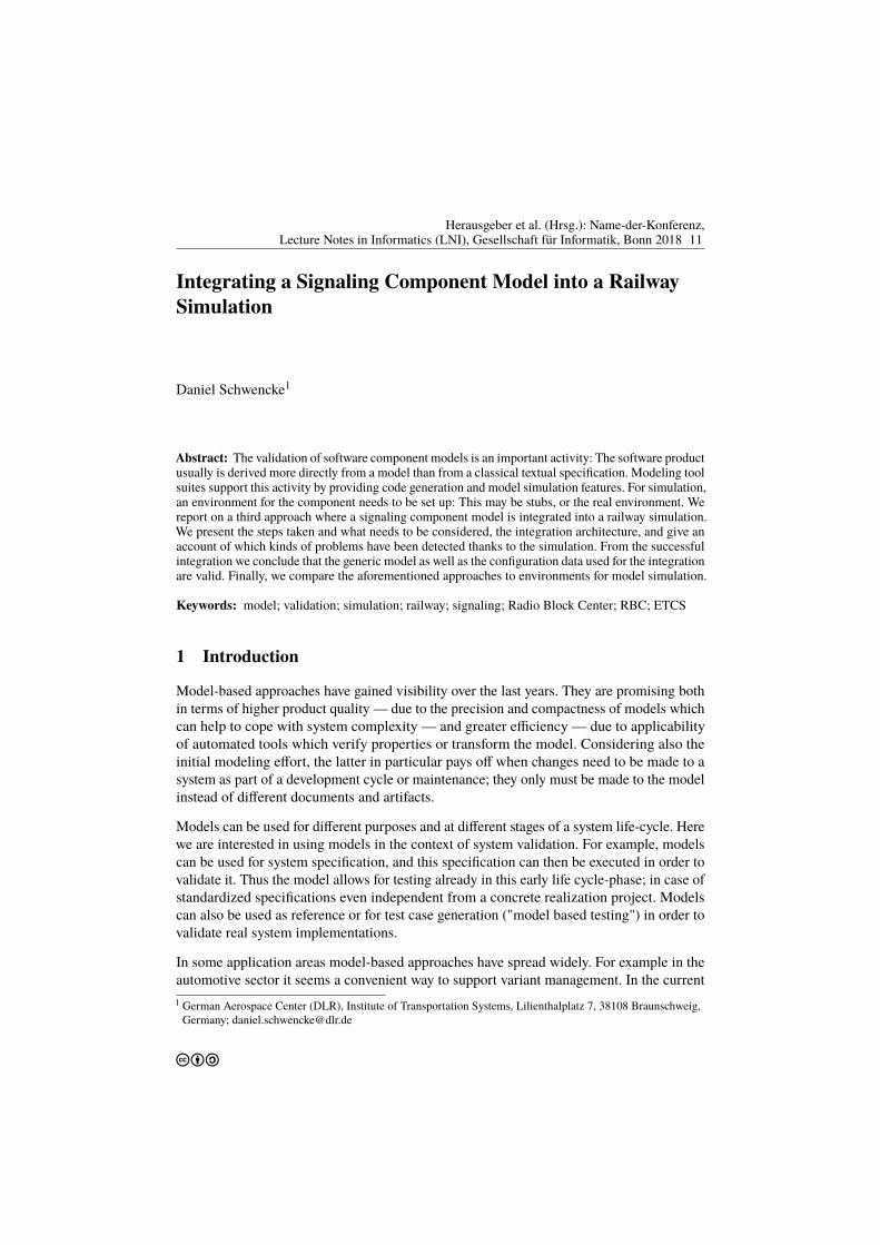
cba
Herausgeber et al. (Hrsg.): Name-der-Konferenz,Lecture Notes in Informatics (LNI), Gesellschaft für Informatik, Bonn 2018 11
Integrating a Signaling Component Model into a RailwaySimulation
Daniel Schwencke1
Abstract: The validation of software component models is an important activity: The software productusually is derived more directly from a model than from a classical textual specification. Modeling toolsuites support this activity by providing code generation and model simulation features. For simulation,an environment for the component needs to be set up: This may be stubs, or the real environment. Wereport on a third approach where a signaling component model is integrated into a railway simulation.We present the steps taken and what needs to be considered, the integration architecture, and give anaccount of which kinds of problems have been detected thanks to the simulation. From the successfulintegration we conclude that the generic model as well as the configuration data used for the integrationare valid. Finally, we compare the aforementioned approaches to environments for model simulation.
Keywords: model; validation; simulation; railway; signaling; Radio Block Center; RBC; ETCS
1 Introduction
Model-based approaches have gained visibility over the last years. They are promising bothin terms of higher product quality — due to the precision and compactness of models whichcan help to cope with system complexity — and greater efficiency — due to applicabilityof automated tools which verify properties or transform the model. Considering also theinitial modeling effort, the latter in particular pays off when changes need to be made to asystem as part of a development cycle or maintenance; they only must be made to the modelinstead of different documents and artifacts.
Models can be used for different purposes and at different stages of a system life-cycle. Herewe are interested in using models in the context of system validation. For example, modelscan be used for system specification, and this specification can then be executed in order tovalidate it. Thus the model allows for testing already in this early life cycle-phase; in case ofstandardized specifications even independent from a concrete realization project. Modelscan also be used as reference or for test case generation ("model based testing") in order tovalidate real system implementations.
In some application areas model-based approaches have spread widely. For example in theautomotive sector it seems a convenient way to support variant management. In the current1 German Aerospace Center (DLR), Institute of Transportation Systems, Lilienthalplatz 7, 38108 Braunschweig,
Germany; [email protected]
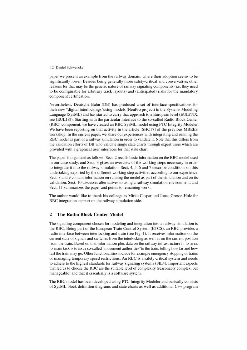
12 Daniel Schwencke
paper we present an example from the railway domain, where their adoption seems to besignificantly lower. Besides being generally more safety-critical and conservative, otherreasons for that may be the generic nature of railway signaling components (i.e. they needto be configurable for arbitrary track layouts) and (anticipated) risks for the mandatorycomponent certification.
Nevertheless, Deutsche Bahn (DB) has produced a set of interface specifications fortheir new "digital interlockings"using models (NeuPro project) in the Systems ModelingLanguage (SysML) and has started to carry that approach to a European level (EULYNX,see [EUL18]). Starting with the particular interface to the so-called Radio Block Center(RBC) component, we have created an RBC SysML model using PTC Integrity Modeler.We have been reporting on that activity in the article [SHC17] of the previous MBEESworkshop. In the current paper, we share our experiences with integrating and running theRBC model as part of a railway simulation in order to validate it. Note that this differs fromthe validation efforts of DB who validate single state charts through expert users which areprovided with a graphical user interfaces for that state chart.
The paper is organized as follows: Sect. 2 recalls basic information on the RBC model usedin our case study, and Sect. 3 gives an overview of the working steps necessary in orderto integrate it into the railway simulation. Sect. 4, 5, 6 and 7 describe conditions on thisundertaking exported by the different working step activities according to our experience.Sect. 8 and 9 contain information on running the model as part of the simulation and on itsvalidation. Sect. 10 discusses alternatives to using a railway simulation environment, andSect. 11 summarizes the paper and points to remaining work.
The author would like to thank his colleagues Mirko Caspar and Jonas Grosse-Holz forRBC integration support on the railway simulation side.
2 The Radio Block Center Model
The signaling component chosen for modeling and integration into a railway simulation isthe RBC. Being part of the European Train Control System (ETCS), an RBC provides aradio interface between interlocking and train (see Fig. 1). It receives information on thecurrent state of signals and switches from the interlocking as well as on the current positionfrom the train. Based on that information plus data on the railway infrastructure in its area,its main task is to issue so-called "movement authorities"to the train, telling how far and howfast the train may go. Other functionalities include for example emergency stopping of trainsor managing temporary speed restrictions. An RBC is a safety critical system and needsto adhere to the highest standards for railway signaling systems (SIL4). Important aspectsthat led us to choose the RBC are the suitable level of complexity (reasonably complex, butmanageable) and that it essentially is a software system.
The RBC model has been developed using PTC Integrity Modeler and basically consistsof SysML block definition diagrams and state charts as well as additional C++ program
Model Integration into Rail Simulation 13
Fig. 1: The RBC as part of the ETCS Level 2 (simplified presentation, ILS = interlocking system).
code. The model exhibits no complete implementation of an RBC, only core functionalitynecessary to operate a demonstration line has been included. However, the functionalityavailable has been modeled in a realistic scope; for example, the RBC is multi-train andmulti-interlocking capable, can be used for arbitrary track layouts, and can be extendedupon demand to include more special functionalities. For more information on the model aswell as on the underlying standards, tools and languages we refer the reader to the articles[SH16; SHC17].
3 Approach
The railway simulation into which the model was to be integrated was given as the oneavailable in DLR’s RailSiTe® lab. It is regularly used for ETCS on-board unit tests, forwhich the lab is accredited, so it supports the simulation of train rides controlled by ETCS.Also, it is regularly used for studies conducted in a train driver simulator. This latter set-upwas utilized for our simulation since it naturally supports validation of an RBC: The outcomeof the most important RBC actions is visible on the driver machine interface (DMI), andthe time of passing a balise group which triggers some RBC action can be detected fromthe front window.
Fig. 2 shows the working steps that have been performed in order to run the RBC modelas part of DLR’s railway simulation. The arrows indicate the order (dependencies) of thesteps; iterations (backwards arrows) occur in many places in practice but have been omittedhere to avoid a cluttered picture. First of all, the model to be integrated has been developedin a way that code could be automatically generated from it. On the lab side, the necessaryinterfaces have been prepared directly on program code level. All of those activities aregeneric (colored blue), i.e. they are independent of a particular railway infrastructure (tracktopology, signal locations, gradient and speed profiles etc.). This is important for signalingsystems as a new development for each specific infrastructure would be unaffordable; but on
14 Daniel Schwencke
Fig. 2: Working steps towards running a signaling component model as part of a railway simulation.Generic development steps are colored blue, steps requiring a specific track layout are colored purple.
the other hand this poses challenges for system validation since the system can be configuredfor arbitrary infrastructures and needs to ensure safe operation in any case. For the purposeof this paper, we shall not discuss this issue further but limit ourselves to showing that wehave kept our model generic and that it can indeed be configured for arbitrary infrastructures,as well as the lab (the corresponding activities are colored purple). Finally, the railwaysimulation of the lab can be run together with the model, i.e. a concrete operational scenariois simulated on the specific infrastructure for which the systems have been configured. Asthe modeling tool suite used provides state simulation capabilities, this can optionally be runin parallel, resulting in animated model diagrams during the railway scenario simulation.
4 Creating a Model Suitable for Integration into a Railway Simulation
As shown in Fig. 2, model development basically comprises four kinds of activities:architectural considerations, structure modeling, modeling of the behavior and addingprogram code to the model. The goal of integration into a railway simulation alreadyinfluences the first activity, since it includes the definition of interfaces of the model, someof which may be connected to the simulation later. In the case of the RBC the latter appliesto the interlocking and train (on-board unit) interfaces, cf. Fig. 3. Luckily, in both caseswe could build on existing standards (the German SCI RBC [SCI14] for the interlockinginterface and ETCS Subset 026 [SS16a] for the train interface) which precisely define themessages that can be exchanged. Those have been implemented in the model (and madeavailable in the lab, see Sect. 6 below). While it made sense to choose the original messages,it was decided to deviate from the original underlying communication mechanisms: Insteadof the DB RaSTA protocol via UPD/IP Ethernet communication demanded by the SCI RBCand instead of the GSM-R radio communication demanded by ETCS, for both interfacesthe messages are transferred via TCP/IP Ethernet between model and lab. This choice didnot only imply easier implementation of the communication, but also could be realized
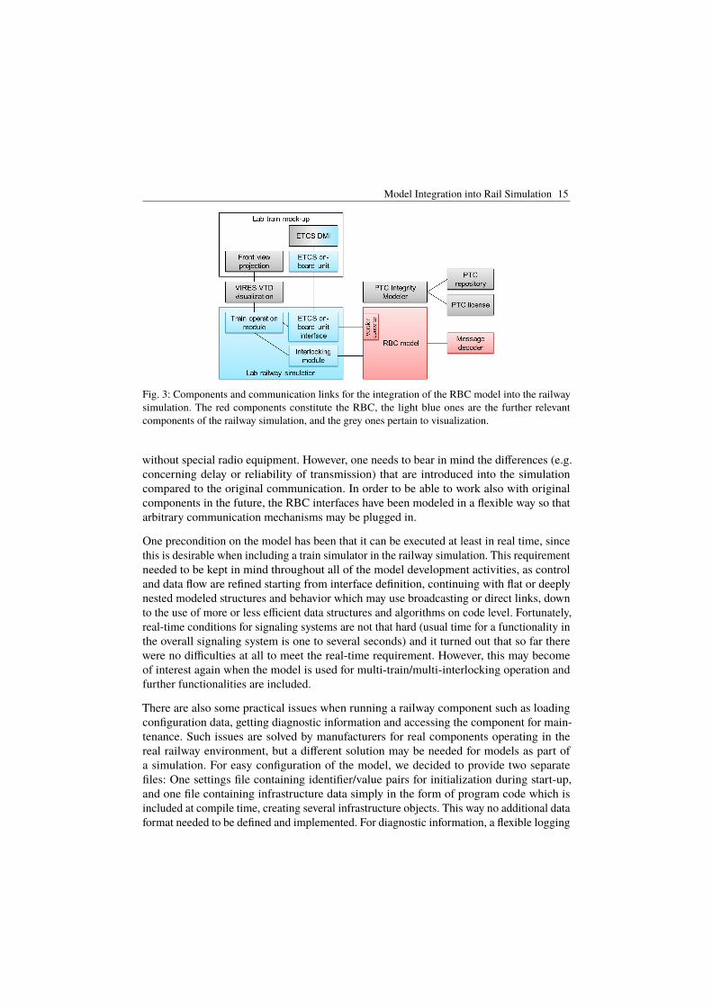
Model Integration into Rail Simulation 15
Fig. 3: Components and communication links for the integration of the RBC model into the railwaysimulation. The red components constitute the RBC, the light blue ones are the further relevantcomponents of the railway simulation, and the grey ones pertain to visualization.
without special radio equipment. However, one needs to bear in mind the differences (e.g.concerning delay or reliability of transmission) that are introduced into the simulationcompared to the original communication. In order to be able to work also with originalcomponents in the future, the RBC interfaces have been modeled in a flexible way so thatarbitrary communication mechanisms may be plugged in.
One precondition on the model has been that it can be executed at least in real time, sincethis is desirable when including a train simulator in the railway simulation. This requirementneeded to be kept in mind throughout all of the model development activities, as controland data flow are refined starting from interface definition, continuing with flat or deeplynested modeled structures and behavior which may use broadcasting or direct links, downto the use of more or less efficient data structures and algorithms on code level. Fortunately,real-time conditions for signaling systems are not that hard (usual time for a functionality inthe overall signaling system is one to several seconds) and it turned out that so far therewere no difficulties at all to meet the real-time requirement. However, this may becomeof interest again when the model is used for multi-train/multi-interlocking operation andfurther functionalities are included.
There are also some practical issues when running a railway component such as loadingconfiguration data, getting diagnostic information and accessing the component for main-tenance. Such issues are solved by manufacturers for real components operating in thereal railway environment, but a different solution may be needed for models as part ofa simulation. For easy configuration of the model, we decided to provide two separatefiles: One settings file containing identifier/value pairs for initialization during start-up,and one file containing infrastructure data simply in the form of program code which isincluded at compile time, creating several infrastructure objects. This way no additional dataformat needed to be defined and implemented. For diagnostic information, a flexible logging
16 Daniel Schwencke
mechanism has been included in the model. For interaction a simple command line menuhas been prepared which provides a convenient way to establish or close RBC connections toindividual components during runtime; for initial connections to be established automaticallyat start-up, default settings can be passed to the RBC via the settings file.
5 Code Generation
In principle, the code generation should be a push button activity and independent of theintegration into the railway simulation, except that it is a first necessary step to transformthe model into an executable form. In practice, it nevertheless is important to understandhow the model is transformed to program code for various reasons:
First of all, code generation may only support part of the model diagrams and elementsavailable in a language or modeling tool. The modeler needs to know this and to stick tothat subset.
In case of a SysML model, there is no completely defined semantics available, but itis given to the model during code generation. For example, the execution order of statechart transitions may depend on the code generator. Thus understanding the code generatorsemantics is necessary if one wants to validate the model by running it in a railway simulation— it may be the case that some unexpected behavior originates from the code generatorsemantics rather than from a model error.
Another questions regards the handwritten code that has been added to the model: Is itintegrated into the code generated from the model’s diagrams as expected by the modeler?For example, under which conditions are initial and final parentheses generated for a codesnippet, and is the handwritten code generated verbatim or is it processed in some way?
We have also seen cases where obviously the code generator produced erroneous code;sometimes the errors result in a compiler message, but sometimes they stay hidden and maybe a subtle source of unexpected behavior. We utilized scripts in order to quickly, reliablyand reproducibly remove such errors from the code files after each code generation. However,those scripts may require maintenance when the model is changed, so it is desirable toretrieve an updated code generator as soon as possible.
Finally, code generators may not only be capable of generating the mere product code, butalso instrumented code for simulation of the model. We decided to use such a feature inorder to have animated state charts available during the railway simulation. We did not useit for manipulation of the running model, which might have caused model behavior whichis otherwise impossible to stimulate. Another issue is to make sure that the additional codein the instrumented version does not change the behavior of the model (except for intendedmanipulations by the user) in any way; in our case, the code generator documentationclaimed this.
Model Integration into Rail Simulation 17
6 Preparation of Lab Interfaces
We have discussed the interfaces between model and lab from the model side already inSect. 4. Of course, the lab needs to provide the counterpart of those interfaces. Since for a labreuse of such interfaces is desirable, they should follow widespread standards, if available.As mentioned above, in our case for both relevant lab-RBC interfaces such standards exist;the ETCS standard had already been implemented in the lab and was then made availableexternally via TCP/IP, and the SCI RBC standard has been newly implemented for the RBClab integration. The interface to the PTC Integrity Modeler was provided by PTC as partof the tool and of the instrumented code (RBC model interface side), based on TCP/IPcommunication as well.
For the RBC train interface further measures in order to ensure interoperability between laband RBC have been necessary. This was due to an old version of the ETCS on-board unitwhich was incompatible with the RBC which was developed according to the newest version.For message decoding on the RBC side, an existing component (external to the model,see Fig. 3) was used which supports the different versions anyway. However, for furtherprocessing a version converter was needed. Although officially not foreseen in the ETCSstandard, such a conversion was inferred from another ETCS specification ([SS16b], wheredata forwarding between RBC and a neighboring RBC of different versions is specified).
The use of the external message decoder component brought up the need for specificationof that particular interface. It was decided to realize this on TCP/IP basis as well (whichdid not cause additional asynchronism problems since the messages passed to the decoderare received by the RBC from the on-board unit via TCP/IP right before). Messages werewrapped, adding IDs in order for the RBC to be able to distinguish which message comingback from the decoder has been received from which train previously.
7 Preparing a Railway Simulation
In order to run a railway simulation, a particular railway line (track topology and signalingequipment) and operational scenario (train type, train control system, route, course ofevents) have to be identified (cf. Fig. 2). In our case the single track line from Braunschweigmain station to Braunschweig Gliesmarode station and the scenario of a train ride startingin ETCS Level 0 with later entry to Level 2 was chosen since for the latter a connectionbetween train and RBC is set up and used. Since that particular line is not equipped withETCS in reality, this has been done (mainly positioning of balises and assignment of balisemessages) according to the applicable DB guidance document [Ril14].
The line and scenario data are then used to prepare the different parts of the simulation:Configuration files for the RBC model and the lab railway simulation are created whichcontain distances, signals, points, balises, speed and gradient profiles, etc. The 3D-world forvisualization of the line has been available already but was adjusted to include the ETCS
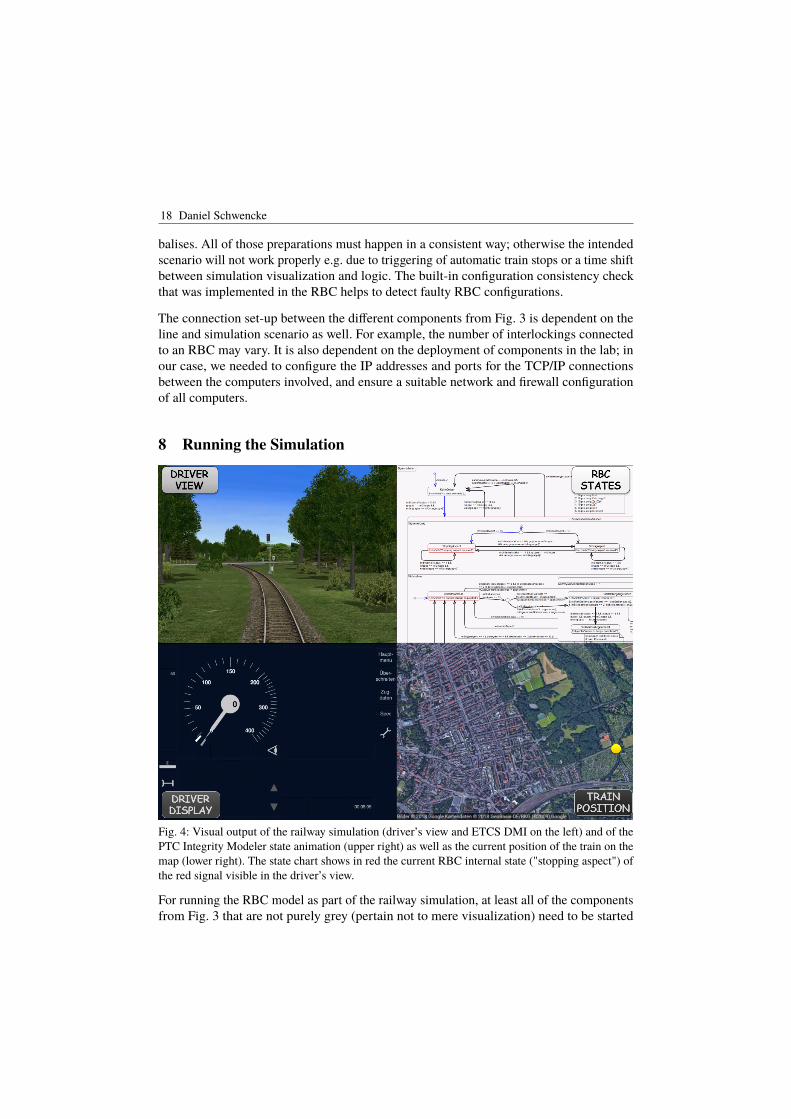
18 Daniel Schwencke
balises. All of those preparations must happen in a consistent way; otherwise the intendedscenario will not work properly e.g. due to triggering of automatic train stops or a time shiftbetween simulation visualization and logic. The built-in configuration consistency checkthat was implemented in the RBC helps to detect faulty RBC configurations.
The connection set-up between the different components from Fig. 3 is dependent on theline and simulation scenario as well. For example, the number of interlockings connectedto an RBC may vary. It is also dependent on the deployment of components in the lab; inour case, we needed to configure the IP addresses and ports for the TCP/IP connectionsbetween the computers involved, and ensure a suitable network and firewall configurationof all computers.
8 Running the Simulation
Fig. 4: Visual output of the railway simulation (driver’s view and ETCS DMI on the left) and of thePTC Integrity Modeler state animation (upper right) as well as the current position of the train on themap (lower right). The state chart shows in red the current RBC internal state ("stopping aspect") ofthe red signal visible in the driver’s view.
For running the RBC model as part of the railway simulation, at least all of the componentsfrom Fig. 3 that are not purely grey (pertain not to mere visualization) need to be started
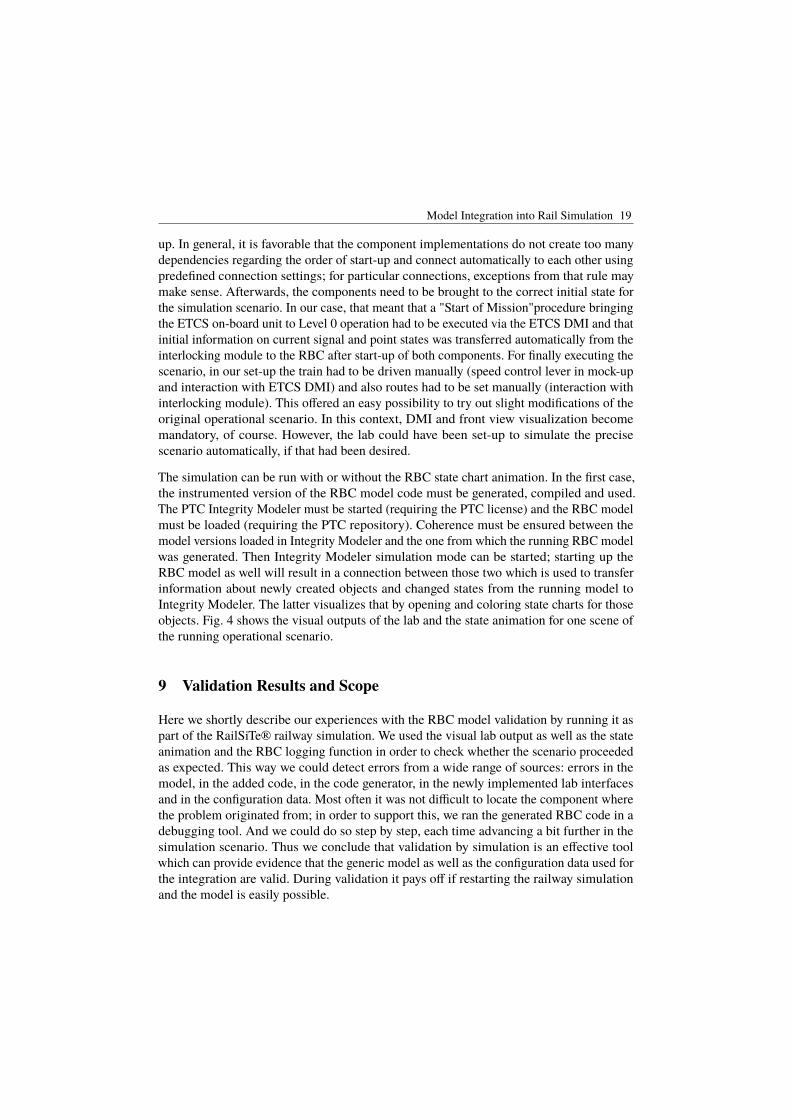
Model Integration into Rail Simulation 19
up. In general, it is favorable that the component implementations do not create too manydependencies regarding the order of start-up and connect automatically to each other usingpredefined connection settings; for particular connections, exceptions from that rule maymake sense. Afterwards, the components need to be brought to the correct initial state forthe simulation scenario. In our case, that meant that a "Start of Mission"procedure bringingthe ETCS on-board unit to Level 0 operation had to be executed via the ETCS DMI and thatinitial information on current signal and point states was transferred automatically from theinterlocking module to the RBC after start-up of both components. For finally executing thescenario, in our set-up the train had to be driven manually (speed control lever in mock-upand interaction with ETCS DMI) and also routes had to be set manually (interaction withinterlocking module). This offered an easy possibility to try out slight modifications of theoriginal operational scenario. In this context, DMI and front view visualization becomemandatory, of course. However, the lab could have been set-up to simulate the precisescenario automatically, if that had been desired.
The simulation can be run with or without the RBC state chart animation. In the first case,the instrumented version of the RBC model code must be generated, compiled and used.The PTC Integrity Modeler must be started (requiring the PTC license) and the RBC modelmust be loaded (requiring the PTC repository). Coherence must be ensured between themodel versions loaded in Integrity Modeler and the one from which the running RBC modelwas generated. Then Integrity Modeler simulation mode can be started; starting up theRBC model as well will result in a connection between those two which is used to transferinformation about newly created objects and changed states from the running model toIntegrity Modeler. The latter visualizes that by opening and coloring state charts for thoseobjects. Fig. 4 shows the visual outputs of the lab and the state animation for one scene ofthe running operational scenario.
9 Validation Results and Scope
Here we shortly describe our experiences with the RBC model validation by running it aspart of the RailSiTe® railway simulation. We used the visual lab output as well as the stateanimation and the RBC logging function in order to check whether the scenario proceededas expected. This way we could detect errors from a wide range of sources: errors in themodel, in the added code, in the code generator, in the newly implemented lab interfacesand in the configuration data. Most often it was not difficult to locate the component wherethe problem originated from; in order to support this, we ran the generated RBC code in adebugging tool. And we could do so step by step, each time advancing a bit further in thesimulation scenario. Thus we conclude that validation by simulation is an effective toolwhich can provide evidence that the generic model as well as the configuration data used forthe integration are valid. During validation it pays off if restarting the railway simulationand the model is easily possible.
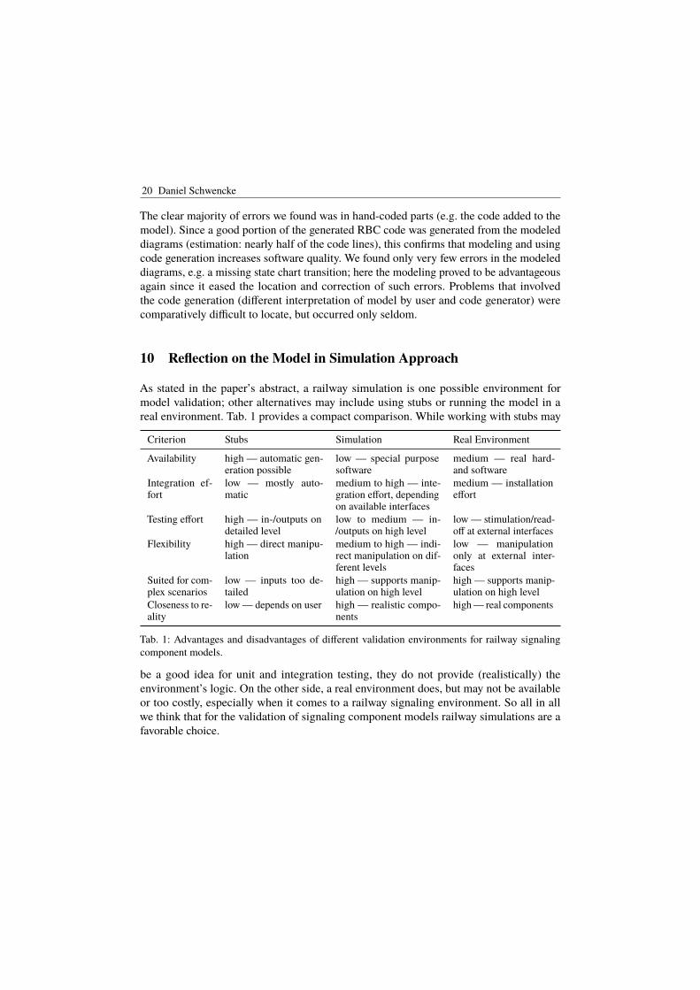
20 Daniel Schwencke
The clear majority of errors we found was in hand-coded parts (e.g. the code added to themodel). Since a good portion of the generated RBC code was generated from the modeleddiagrams (estimation: nearly half of the code lines), this confirms that modeling and usingcode generation increases software quality. We found only very few errors in the modeleddiagrams, e.g. a missing state chart transition; here the modeling proved to be advantageousagain since it eased the location and correction of such errors. Problems that involvedthe code generation (different interpretation of model by user and code generator) werecomparatively difficult to locate, but occurred only seldom.
10 Reflection on the Model in Simulation Approach
As stated in the paper’s abstract, a railway simulation is one possible environment formodel validation; other alternatives may include using stubs or running the model in areal environment. Tab. 1 provides a compact comparison. While working with stubs may
Criterion Stubs Simulation Real Environment
Availability high — automatic gen-eration possible
low — special purposesoftware
medium — real hard-and software
Integration ef-fort
low — mostly auto-matic
medium to high — inte-gration effort, dependingon available interfaces
medium — installationeffort
Testing effort high — in-/outputs ondetailed level
low to medium — in-/outputs on high level
low — stimulation/read-off at external interfaces
Flexibility high — direct manipu-lation
medium to high — indi-rect manipulation on dif-ferent levels
low — manipulationonly at external inter-faces
Suited for com-plex scenarios
low — inputs too de-tailed
high — supports manip-ulation on high level
high — supports manip-ulation on high level
Closeness to re-ality
low — depends on user high — realistic compo-nents
high — real components
Tab. 1: Advantages and disadvantages of different validation environments for railway signalingcomponent models.
be a good idea for unit and integration testing, they do not provide (realistically) theenvironment’s logic. On the other side, a real environment does, but may not be availableor too costly, especially when it comes to a railway signaling environment. So all in allwe think that for the validation of signaling component models railway simulations are afavorable choice.
Model Integration into Rail Simulation 21
11 Conclusion and Future Work
In this article, we have reported on the validation of a railway signaling component modelby integrating it into a railway simulation. More precisely, a SysML model of an RBC hasbeen integrated and validated into DLR’s RailSiTe® laboratory.
A first conclusion, from the mere fact that the model could be integrated and ran well in thesimulation environment, is the general feasibility of modeling railway signaling componentsgenerically and for realistic applications. Further steps to support this statement would be totry the same approach with different components, with different configurations, and withcomplete component models. Some work remains to be done if the development approachis to be applied for real signaling components: A detailed semantics for SysML (which maybe part of the upcoming SysML 2.0 standardization work) would be needed as well as aconcept for migration to the new approach and a certified code generator. Most probable, thiswill imply further restrictions on the model artifacts and programming language constructsused. At least the model at hand was developed to result in deterministic code (i.e. withoutconcurrency) and avoiding circular control flow between the state charts.
Depending on the interfaces available and the configuration of the lab for a particularoperational scenario, the integration of a model into a railway simulation may requiresome effort; certainly, there is potential for more efficient or automated ways to distributeconfiguration data from a single source to the different components of the simulation.However, we were pleased to see that the combination of model and railway simulationallowed for efficient validation: The model obviously resulted in a high initial quality of thecomponent and provided the possibility for visual inspection during simulation by using thestate animation feature; and the simulation allowed for convenient stimulation and outputretrieval on the high-level interfaces like DMI and line visualization, while offering thepossibility to dig deeper when erroneous behavior was observed. It also turned out thatthe inherent parallel validation of the configuration data and the newly implemented labinterfaces was not much of a problem since the assignment of errors to the different possiblesources was quickly found in most cases, whereas tracking errors related to code generationwas more difficult. All in all, we conclude that validation of models by running them inrailway simulations is a practically feasible and may even be the favorable approach foroverall component validation. Provided that some particular requirements of the approach,which we aimed to describe in this paper, are taken into consideration early, lab integrationcan be organized in a smooth way.
In the future, we would like to investigate and exploit the benefits of a validated model. Itmay be used as a reference for real signaling components, or for test case generation forsuch components. It would be nice to see whether the quality of the component can beincreased further e.g. due to the extra model coverage criteria generated test cases can fulfill.We also expect a clear decrease in maintenance effort of test cases (simply change modeland generate again).

22 Daniel Schwencke
References
[EUL18] EULYNX Website, 2018, url: https://www.eulynx.eu, visited on: 02/19/2018.[Ril14] LST-Anlagen planen: Grundsätze zur Erstellung der Ausführungsplanung PT1
für ETCS Level 2, tech. rep. Richtlinie 819.1344, draft, DB Netze AG, Apr. 24,2014.
[SCI14] SCI-RBC – FAS TAS TAV Schnittstelle ESTW-RBC V2. Baseline 0.19, tech.rep., DB Netze AG, June 6, 2014.
[SH16] Schwencke, D.; Hungar, H.: Development of Reference Models of SignalingComponents: the Example of the Radio Block Center. Signal+Draht 108/9,pp. 24–32, 2016.
[SHC17] Schwencke, D.; Hungar, H.; Caspar, M.: Between Academics and Practice:Model-based Development of Generic Safety-Critical Systems. In (Huhn, M.;Hungar, H.; Riebisch, M.; Voss, S., eds.): Modellbasierte Entwicklung einge-betteter Systeme XIII (Proceedings of the Dagstuhl MBEES 2017 workshop).fortiss GmbH, Munich, pp. 1–18, 2017, url: http://download.fortiss.org/public/mbees/mbees2017_proceedings.pdf.
[SS16a] SUBSET-026 – System Requirements Specification. Version 3.6.0, tech. rep.,ERTMS, June 15, 2016, url: http://www.era.europa.eu/Core-Activities/ERTMS/Pages/Set-of-specifications-3.aspx.
[SS16b] SUBSET-039 - FIS for the RBC/RBC Handover. Version 3.2.0, tech. rep.,ERTMS, June 15, 2016, url: http://www.era.europa.eu/Core-Activities/ERTMS/Pages/Set-of-specifications-3.aspx.