tacho meter tm- 4100 / tm- 4100dponpe.com/download/tenmars/manual/tm- 4100_tm- 4100d.pdf ·...
TRANSCRIPT
TACHO Meter TM- 4100 / TM- 4100D
TENMARS ELECTRONICS CO., LTD
User’s Manual
HB2TM4100001

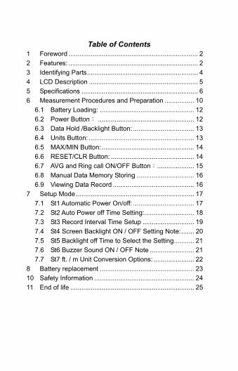
Table of Contents 1 Foreword ...................................................................... 2 2 Features: ...................................................................... 2 3 Identifying Parts............................................................ 4 4 LCD Description ........................................................... 5 5 Specifications ............................................................... 6 6 Measurement Procedures and Preparation ................ 10
6.1 Battery Loading: ................................................... 12 6.2 Power Button: .................................................... 12 6.3 Data Hold /Backlight Button: ................................. 13 6.4 Units Button: ......................................................... 13 6.5 MAX/MIN Button: .................................................. 14 6.6 RESET/CLR Button: ............................................. 14 6.7 AVG and Ring call ON/OFF Button:.................... 15 6.8 Manual Data Memory Storing ............................... 16 6.9 Viewing Data Record ............................................ 16
7 Setup Mode................................................................ 17 7.1 St1 Automatic Power On/off: ................................. 17 7.2 St2 Auto Power off Time Setting:........................... 18 7.3 St3 Record Interval Time Setup ............................ 19 7.4 St4 Screen Backlight ON / OFF Setting Note:....... 20 7.5 St5 Backlight off Time to Select the Setting........... 21 7.6 St6 Buzzer Sound ON / OFF Note ........................ 21 7.7 St7 ft. / m Unit Conversion Options: ...................... 22
8 Battery replacement ................................................... 23 10 Safety Information ...................................................... 24 11 End of life ................................................................... 25

TM-4100/TM-4100D
2
1 Foreword Thank you for purchasing this tacho meter. Please, read this user’s manual before you operate it.
2 Features
Measurement method: Using red visible spectrum light source and reflective tape or a reflector plate.
Reflex indicators : When you receive the reflected signals the RING bright LCD screen locked. The buzzer.
Features : Max / Min display, display hold, on average, automatic shutdown, buzzer, backlight.
Contact measurement and non-contact, non-contact measuring the distance from the 50 ~ 500mm, allowing in this way would be dangerous to use the case of the measured object. Light weight, make the instrument easier to handle.
Low battery detector “ ”. Manual data memory storing : 200 data
TM-4100/TM-4100D
3
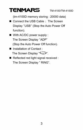
(tm-4100D memory storing : 20000 data) Connect the USB Cable : The Screen Display ’’USB’’ (Stop the Auto Power Off function).
With AC/DC power supply : The Screen Display ‘’ADP” (Stop the Auto Power Off function).
Installation of Contact : The Screen Display ” ”. Reflected red light signal received : The Screen Display ” RING”.
TM-4100/TM-4100D
4
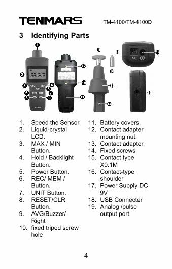
3 Identifying Parts
1. Speed the Sensor. 2. Liquid-crystal
LCD. 3. MAX / MIN
Button. 4. Hold / Backlight
Button. 5. Power Button. 6. REC/ MEM /
Button. 7. UNIT Button. 8. RESET/CLR
Button. 9. AVG/Buzzer/
Right 10. fixed tripod screw
hole
11. Battery covers. 12. Contact adapter
mounting nut. 13. Contact adapter. 14. Fixed screws 15. Contact type
X0.1M 16. Contact-type
shoulder 17. Power Supply DC
9V 18. USB Connecter 19. Analog /pulse
output port
TM-4100/TM-4100D
5
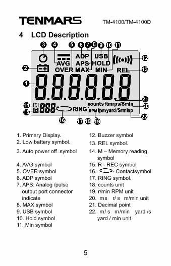
4 LCD Description
1. Primary Display. 12. Buzzer symbol 2. Low battery symbol. 13. REL symbol. 3. Auto power off .symbol 14. M – Memory reading
symbol 4. AVG symbol 15. R - REC symbol 5. OVER symbol 16. - Contactsymbol. 6. ADP symbol 17. RING symbol. 7. APS: Analog /pulse
output port connector indicate
8. MAX symbol 9. USB symbol 10. Hold symbol 11. Min symbol
18. counts unit 19. r/min RPM unit 20. ms r/s m/min unit 21. Decimal point 22. m/s m/min yard /s
yard / min unit

TM-4100/TM-4100D
6
5 Specifications Measurement method : Using red visible
spectrum light source and reflective tape or a reflective plate.
Display : Liquid-crystal (LCD), 6 digits Range switching: Automatic. Contactless measurement detection range :
50mm to 500mm (1.97" to 19.7") Sampling period : 62.5 ms to 2 s (depending
on usage conditions). Measuring range :
Measuring range (non-contact, AVG = ON) [r/s](0.5000~1.9999)~(200.0~1600.0) [ms](0.6000~1.9999)~(200.0~1999.9). Measuring range (contact, AVG = ON) [m/m](1.500~19.999)~(200.0~1999.9) [ms](0.0250~1.9999)~(20.00~33.30)
Only speed measurement : precision required for the above plus ±0.5%rdg.
Display refresh rate : Approx. 0.5 to10 times/sec.
Functions : MAX/MIN display, Display hold, Average, Auto power save, Buzzer, Backlight function.

TM-4100/TM-4100D
7
Operating temperature humidity range : 0°C to + 40°C. 25% to 75 % RH.
Storage temperatures humidity range : -10°C to +60°C. 0% to 80% RH.
Power supply : 9V alkaline battery×1. AC Adapter : 9V(1A) (Option). Maximum rated power : 0.5VA. Compatible jack diameter : 3.5mm. Output Level : 0 to 3.3V.
(Active low, low level fixed at 300μs) . Instrument output setting
(analog output/pulse output). Continuous operating time : Approx. 24 hours
(TM4100) . Dimensions : Approx. 186x70x36 mm
(L x W x H). Mass : Approx. 200g. Accessories : 9V alkaline battery ×1, Carrying
case ×1, REFLECTIVE TAPE ×1 sheet per piece).
Ranges and measurement ranges: NOTE 1 : the lowermost digit is fixed at 0 at
speeds of 20,000 r/min and over. NOTE 2 : the lowermost digit is fixed at 0 when
the averaging setting is off.
TM-4100/TM-4100D
8
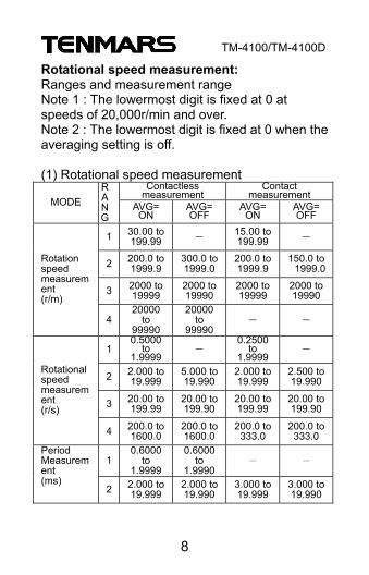
Rotational speed measurement: Ranges and measurement range Note 1 : The lowermost digit is fixed at 0 at speeds of 20,000r/min and over. Note 2 : The lowermost digit is fixed at 0 when the averaging setting is off. (1) Rotational speed measurement
Contactless measurement
Contact measurement
MODE RANG
AVG= ON
AVG= OFF
AVG= ON
AVG= OFF
1 30.00 to199.99 - 15.00 to
199.99 -
2 200.0 to1999.9
300.0 to1999.0
200.0 to1999.9
150.0 to 1999.0
3 2000 to19999
2000 to19990
2000 to19999
2000 to 19990
Rotation speed measurement (r/m)
420000
to 99990
20000 to
99990 - -
10.5000
to 1.9999
- 0.2500
to 1.9999
-
2 2.000 to19.999
5.000 to19.990
2.000 to19.999
2.500 to 19.990
3 20.00 to199.99
20.00 to199.90
20.00 to199.99
20.00 to 199.90
Rotational speed measurement (r/s)
4 200.0 to1600.0
200.0 to1600.0
200.0 to333.0
200.0 to 333.0
10.6000
to 1.9999
0.6000 to
1.9990- -
Period Measurement (ms)
2 2.000 to19.999
2.000 to19.990
3.000 to19.999
3.000 to 19.990
TM-4100/TM-4100D
9
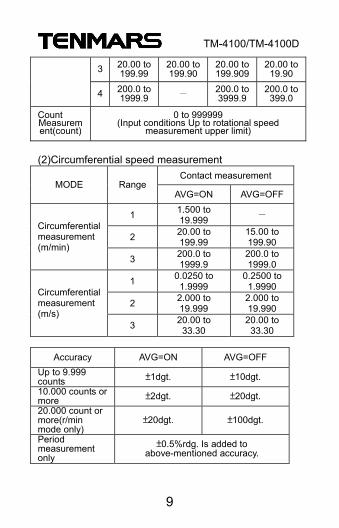
3 20.00 to199.99
20.00 to199.90
20.00 to199.909
20.00 to 19.90
4 200.0 to1999.9 - 200.0 to
3999.9200.0 to 399.0
Count Measurement(count)
0 to 999999 (Input conditions Up to rotational speed
measurement upper limit)
(2)Circumferential speed measurement
Contact measurement MODE Range
AVG=ON AVG=OFF
1 1.500 to 19.999 -
2 20.00 to 199.99
15.00 to 199.90
Circumferential measurement (m/min)
3 200.0 to 1999.9
200.0 to 1999.0
1 0.0250 to 1.9999
0.2500 to 1.9990
2 2.000 to 19.999
2.000 to 19.990
Circumferential measurement (m/s)
3 20.00 to 33.30
20.00 to 33.30
Accuracy AVG=ON AVG=OFF
Up to 9.999 counts ±1dgt. ±10dgt. 10.000 counts or more ±2dgt. ±20dgt. 20.000 count or more(r/min mode only)
±20dgt. ±100dgt.
Period measurement only
±0.5%rdg. Is added to above-mentioned accuracy.
TM-4100/TM-4100D
10
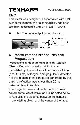
EMC This meter was designed in accordance with EMC Standards in force and its compatibility has been tested in accordance with EN61326-1 (2006).
Ac / The pulse output wiring diagram:
6 Measurement Procedures and Preparation
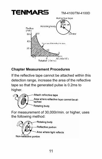
Precautions in Measurement of High-Rotation Objects Detection of reflected light uses modulated light is input for a fixed period of time (about 0.2ms) or longer, a single pulse is detected. For this reason, if the light pulse generated by the passing reflective tape is less than 0.2ms detection is not possible. The range that can be detected with a 12mm square target of reflective tape is indicated below. ※Radius is the distance between the center of
the rotating object and the center of the tape.
TM-4100/TM-4100D
11
Chapter Measurement Procedures If the reflective tape cannot be attached within this detection range, increase the area of the reflective tape so that the generated pulse is 0.2ms to higher.
For measurement of 30,000r/min. or higher, uses the following method:

TM-4100/TM-4100D
12
For measurement of 30,000 r/min. or higher, use the following. Method : Chapter Measurement Procedures If the reflective tape cannot be attached within this detection range, increase the area of the reflective tape so that the generated pulse is 0.2ms to higher.
6.1 Battery Loading: Remove the battery cover on the back and put a 9V battery inside. Battery replacement: When the symbol of “ ” appears on the LCD display, the battery should be replaced with a new one. The battery symbol will be displayed on the LCD, this symbol “ ” is a battery low indicator.
6.2 Power Button: Press “ ” button to power on. Again Press “ ” button to power off.

TM-4100/TM-4100D
13
6.3 Data Hold /Backlight Button: Press the “ ”button, LCD display“ ”,
Lock reading, and then a“ ” lifting "lock.
> > > >
Press the “ ” button for more than 2 seconds
to turn on or turn off the backlight function
Backlight light turns off automatically after 30
seconds.
6.4 Units Button:
Press “ ” button to change the unit. Possible
Units : Non-contact : RPM r/min ms. counts /s Contact : RPM r/min ms counts>>ft/s ft/min yard/s yard/min r/s RPM r/min ms counts m/s m/min r/s

TM-4100/TM-4100D
14
6.5 MAX/MIN Button: Configuration meshed : Repeated key
input Operation description :
Normal value→Maximum value ( lights up)
→Minimun value ( lights up) ※ This function is not available during count measurement (the key is disabled).
6.6 RESET/CLR Button:
Operation method : key input Operation description : The current value, maximum value, minimum value, count measured value, and circumferential speed value are reset to zero.

TM-4100/TM-4100D
15
Notes : The measured value is also cleared when switching measurement modes and changing the averaging setting.
6.7 AVG and Ring call ON/OFF Button: Operation method : key input
Operation description:
The current value, maximum value, minimum
value is reset to zero.
Note:
The measured value is also cleared when
switching measurement modes and changing the
averaging setting.
Push“ ” button to enable or disable AVG
mode. Press “ ” key more 2 seconds to enable or disable the buzzer. When the “ ” symbol is on the LCD Display which means the buzzer is on.
TM-4100/TM-4100D
16
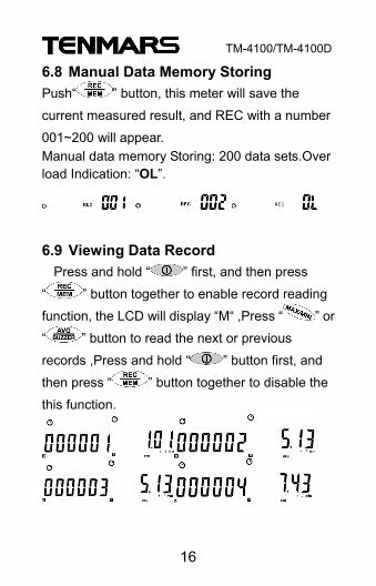
6.8 Manual Data Memory Storing Push“ ” button, this meter will save the
current measured result, and REC with a number
001~200 will appear. Manual data memory Storing: 200 data sets.Over load Indication: “OL”.
6.9 Viewing Data Record Press and hold “ ” first, and then press
“ ” button together to enable record reading
function, the LCD will display “M“ ,Press “ ” or
“ ” button to read the next or previous
records ,Press and hold “ ” button first, and
then press “ ” button together to disable the
this function.

TM-4100/TM-4100D
17
7 Setup Mode Press and hold “ ” button first ,and then
press“ ” button to enter the Setup Mode set1. Press “ ” button to change the setup function from set1 to set7 mode, LCD will display from set1 to set7. Press“ ” button to exit the setup mode. Set 1: Automatic shutdown on / off setting. Set 2: Adjust auto-shutdown time setting. Set 3: Record time: time. Points second set. Set 4: Screen backlight on / off setting. Set 5: backlight Seconds and setting Set 6: Buzzer sounds on / off setting. Set 7: ft. and m setting. Setting method, see the 7.1 ~7.7 paragraphs.
7.1 St1 Automatic Power On/off: After entering st1 screen then click " " to
switch from " " to " " then click " "
button to confirm the action, on behalf of not
automatically shut down. Test mode LCD screen

TM-4100/TM-4100D
18
no longer displays " " symbol. Will be appeared on the LCD display.
To reply to automatic shutdown feature, please
follow the steps to cancel automatic shutdown st1,
LCD screen, select the " " symbol, then click "
" button to confirm the test status LCD
screen on the " " symbol to restore light, for
automatic shutdown.
Press “ ” key to save and exit.
7.2 St2 Auto Power off Time Setting: After entering to St2 automatic shutdown time
setting function, then the LCD screen will display
the time, st2, and symbols together to adjust
minutes.
Press " " button or " " button to enter the
value to adjust the duration of the auto power off
time.

TM-4100/TM-4100D
19
Setting Auto Power Off time from:15 to 99
minutes.
Press " " button and enter the settings from
the setting mode.
The auto power off time default setting is 15
minutes.
>>>
7.3 St3 Record Interval Time Setup Entered into the records of each storage interval st3 time setting By the press " " button or " " button to
modify the time value of the duration.
Press " " button or " " button to shift the

TM-4100/TM-4100D
20
cursor to move from hour to minute, then to
second for the setup.
Press " " button to determine the set of the time, and from the setting mode.
7.4 St4 Screen Backlight ON / OFF Setting Note:
After entering st4 screen then click " " to
switch from “ " to " " then click "
“button to confirm the action, performed without
backlight.
To reply to st4 backlight ON, please follow the
steps to cancel without backlight unit, select the
LCD screen on the “ " symbol, then click”
“button to confirm, on the implementation of
a backlight. Auto Power off Time function
TM-4100/TM-4100D
21
>>>
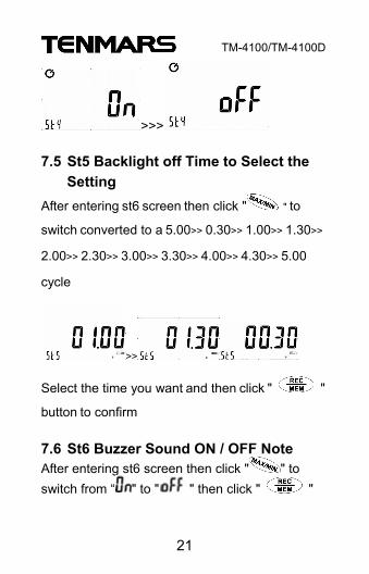
7.5 St5 Backlight off Time to Select the Setting
After entering st6 screen then click " " to
switch converted to a 5.00>> 0.30>> 1.00>> 1.30>>
2.00>> 2.30>> 3.00>> 3.30>> 4.00>> 4.30>> 5.00
cycle
>>
Select the time you want and then click " "
button to confirm 7.6 St6 Buzzer Sound ON / OFF Note After entering st6 screen then click " " to switch from “ " to " " then click " "
TM-4100/TM-4100D
22
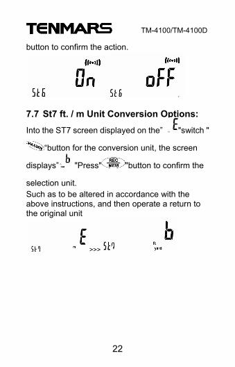
button to confirm the action.
7.7 St7 ft. / m Unit Conversion Options:
Into the ST7 screen displayed on the” "switch "
“button for the conversion unit, the screen
displays” "Press" "button to confirm the
selection unit. Such as to be altered in accordance with the above instructions, and then operate a return to the original unit
>>>
TM-4100/TM-4100D
23
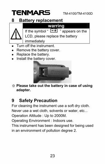
8 Battery replacement warring
If the symbol “ ” appears on the LCD, please replace the battery immediately
Turn off the instrument. Remove the battery cover. Replace the battery. Install the battery cover.
※ Please take out the battery in case of using
adapter.
9 Safety Precaution For cleaning the instrument use a soft dry cloth. Never use a wet cloth, solvents or water, etc... Operation Altitude : Up to 2000M. Operating Environment : Indoors use. This instrument has been designed for being used in an environment of pollution degree 2.
TM-4100/TM-4100D
24
10 Safety Information
DANGER
In some cases, work in the vicinity of powerful radiation sources can be a risk of your life. Be aware that persons with electronic implants (e.g. cardiac pacemakers) are subject to particular dangers in some cases. Observe the local safety regulations of the facility operation.
Observe the operating instructions for equipment, which is used to generate, conduct, or consumer electromagnetic energy. Be aware that secondary radiators (e.g. reflective objects such as a metallic fence) can cause a local amplification of the field. Be aware that the field strength in the near vicinity of radiators increases proportionally to the inverse cube of the distance. This means that enormous field strengths can result in the immediate vicinity of small radiation sources (e.g. leak in wave guides, inductive ovens) Field strength measuring device can underrate pulsed signals. Particularly with radar signals, significant measurement errors
TM-4100/TM-4100D
25
can arise. All field strength measuring devices have a limited specified frequency range. Fields with spectral components outside of this frequency range are generally incorrectly evaluated and tend to be underrated. Before using field strength measuring devices, you should thus be certain that all field components to be measured lie in the specified frequency range of the measuring device.
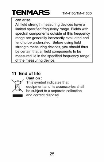
11 End of life
Caution : This symbol indicates that equipment and its accessories shall be subject to a separate collection and correct disposal

Professional Electrical and Environment Test & Measurement
Instruments: Battery Capacity ,Impedance Tester,
TACHO Meter ,LED light meter ,Temperature & Humidity meter ,Infrared Thermometer ,Sound level meter ,Light meter ,EMF meter ,UV Light meter ,RF mete r ,Hot wire Anemometer ,CO meter ,Anemometer ,Lan cable tester ,CO2 meter ,Solar power meter ,Radiation meter,
Clamp meter ,Multimeter ,Phase Rotation test, Digital Insulation tester.
Our products of high quality are selling
well all over the world
TENMARS ELECTRONICS CO., LTD 6F, 586, RUI GUANG ROAD, NEIHU,
TAIPEI 114, TAIWAN. E-mail : [email protected]
Http : //www.tenmars.com