table of contents - the steel network · pdf fileload bearing wall members. 122017 | the steel...
TRANSCRIPT


022018 | The Steel Network, Inc.www.steelnetwork.com | 1-888-474-4876Page | Load Bearing Wall Members 1
Copyright © 2018 The Steel Network Inc. All rights reserved. No part of this publication may be reproduced in whole or in part by any method without the prior written consent of The Steel Network, Inc.
Table of Contents
Table of ContentsSigmaStud® Introduc on...........................................................................................................................................2SigmaStud® Product Profi le....................................................................................................................................3-4SigmaStud® Sec on Proper es...............................................................................................................................5-6SigmaStud® Design Example......................................................................................................................................7SigmaStud® Combined Axial & Lateral Load Tables...............................................................................................8-15SigmaStud® STC Ra ngs and UL Assemblies............................................................................................................16SigmaStud® Web Reinforcement.............................................................................................................................17SigmaTrak® Introduc on..........................................................................................................................................18SigmaTrak® Sec on Proper es............................................................................................................................19-20Design Assist Services..............................................................................................................................................21Temporary Bracing...................................................................................................................................................22Construc on Guide.............................................................................................................................................23-24Bridging Example Problem.......................................................................................................................................25Bridging Anchorage..................................................................................................................................................26S ff Wall® Shear Wall System Introduc on.........................................................................................................27-28S ff Wall® SWS Design.........................................................................................................................................29-30Pre-Assembled Columns/Boots................................................................................................................................31S ff Wall® Column Product Profi le.......................................................................................................................32-35S ff Wall® Column Sec on Proper es.......................................................................................................................36S ff Wall® Column Axial Load Tables....................................................................................................................37-39S ff Wall® Boots..................................................................................................................................................40-41S ff Wall® SWS Example Problem.......................................................................................................................42-44Flat Strap..................................................................................................................................................................45TightStrap® Strap Tensioner......................................................................................................................................46Other Design Considera ons for Shear Wall Systems..............................................................................................47SWS Example Details................................................................................................................................................48Floor Systems Introduc on…………………….................................................................................................................49PrimeJoist® Introduc on………………………….........................................................................................................……50Floor System Fire & Sound Tested Assemblies………………....................................................................................……51Floor System Design Considera ons…………….......................................................................................................….52PrimeJoist® Product Profi le......................................................................................................................................53PrimeJoist® Sec on Proper es.................................................................................................................................54Allowable Floor Joist Span Tables………………................................................................................…………………….55-61Allowable Web Crippling…………......................................................................................................………………….62-64Floor Joist Framing Solu ons…........................................................................................................................……….65PrimeJoist® Example Details….................................................................................................................……………….66SteelSmart® System Design So ware.......................................................................................................................67
About The Steel Network, Inc.:The Steel Network, Inc. (TSN) provides solu ons for all standard light steel framing applica ons, including load-bearing mid-rise construc on systems, curtain wall systems, fl oor joist systems, rigid connectors, ver cal defl ec on connectors, lateral dri connectors and anchorage connectors. Substan al eff ort has been made by the industry to standardize construc on prac ces to ensure the posi ve connec ons of light steel framing components. Toward this end, all TSN products have undergone extensive fi eld and laboratory tes ng to achieve complete solu ons for both designers and installers. TSN’s load bearing mid-rise construc on system is widely used in commercial and government construc on, such as hotels, dormitories and military barracks.
TSN’s compe ve advantage lies in the cost savings, rapid construc on and green design/construc on op ons provided by its core product lines, SigmaStud® and S ff Wall® Load-bearing Shear Wall System, PrimeJoist®, JamStud®, BridgeClip®, Ver Clip®, Dri Clip®, PrimeWall® and Engineering So ware.
Light Steel Framing Members

The Steel Network, Inc. | 022018 www.steelnetwork.com | 1-888-474-4876 Load Bearing Wall Members | Page 2
SigmaStud® Introduction
Weight Advantages
• Axial load capacity tables compa ble with recent code changesEngineering Advantages
• Increased load capacity over similar standard “C-shaped” stud (14ga “C-shaped” to 18ga “SG” common)
• May eliminate double studs and their a achments to each other• Compa ble with all common types of fl oor systems and designs• Accelerate construc on schedules
Performance Improvements
• Screw size decreases with thinner material thickness of member material, facilita ng faster connec ons
• Larger fl ange width increases area for fasteners
Fastener Effi ciencies
• Lighter weight results in easier handling & shipping effi ciencies• Reduc on of wall mass & labor costs• 80% lighter than concrete/masonry block, op mizing founda on thickness
BackgroundSigmaStud® is a breakthrough in the load-bearing steel stud industry, producing significant increases in load capacity when compared with conventional “C” Shaped studs. SigmaStud’s unique configuration provides installation and design advantages which create efficiencies no other light steel framing (LSF) load bearing wall stud can provide. Each bend made to a flat LSF element increases load capacity over a standard stud section with the same material thickness. The return lips present in SigmaStud also increase capacity, delivering the most efficient LSF load-bearing stud member available. SigmaStud redefi nes previous limita ons considered for u liza on of steel studs in building construc on, producing more cost-eff ec on op ons for designing load bearing walls for clients. TSN’s 600SG™ and 800SG™ product lines are for 6” and 8” walls.
Benefi ts That Add Value:
Design Comparison of SigmaStud® and Standard “C-Shape” StudsDesign Assumptions: Wall height: 9 feet; Bridging at 48" o.c. (vertically); Stud Spacing at 16" o.c.; Single or Back-to-Back Members Only;
L/180 Deflection; Fy = 50 ksi for Both C-Shape and SigmaStud; 5 psf Lateral Load; No Load Reductions Taken.
Axial Load “C” Shape, 1 ⅝” Flange “C” Shape, 2” Flange SigmaStud® Section
Comparison Conclusion
4k 600S162-54 600S200-43 600SG162-33 The data presents tangible examples of the exceptional value SigmaStud provides for designers, installers, and owners. In each case, SigmaStud represents a thinner and lighter option, resulting in significant material and labor efficiencies. As the axial load increases, the differences between a single member and 2 or even 3 “ganged” members become even more evident. The ganged members should be connected, either back-to-back or lip-to-lip. Back-to-back ganged studs are connected with either an engineered weld, flat strap and screws along the flanges, or screws through each web placed vertically at 24”o.c. (typical). Use of a single SigmaStud section eliminates the additional engineering as well as the installation of these elements. Contact TSN’s technical
support team for design recommendations.
8k 600S162-97 600S200-68 600SG200-43
12k (2) 600S162-54 600S200-97 600SG250-54
16k (2) 600S162-68 (2) 600S200-54 600SG250-68
20k (2) 600S162-97 (2) 600S200-68 600SG250-97
24k (2) 600S162-97 (2) 600S200-97 600SG250-97 or(2) 600SG250-54
30k (3) 600S162-97 (2) 600S200-97 600SG300-118 or(2) 600SG250-68
SigmaStud®
Patent Pending
Material Proper es:ASTM A1003/A1003M or ASTM A653/A653M, Grade 50(340), 50ksi (340MPa) minimum yield strength, 65ksi (450 MPa) minimum tensile strength, G-60 (Z180) hot-dipped galvanized coating; or equivalent.
Load Bearing Wall Members
022018 | The Steel Network, Inc.www.steelnetwork.com | 1-888-474-4876Page | Load Bearing Wall Members 3
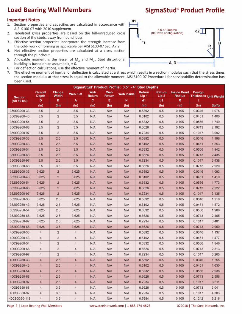
Important Notes1. Section properties and capacities are calculated in accordance with
AISI S100-07 with 2010 supplement.2. Tabulated gross properties are based on the full-unreduced cross
section of the studs, away from punchouts.3. Effective section properties incorporate the strength increase from
the cold- work of forming as applicable per AISI S100-07 Sec. A7.2.4. Net effective section properties are calculated at a cross section
through the punchout.5. Allowable moment is the lesser of Mal and Mad. Stud distortional
buckling is based on an assumed k = 0.6. For deflection calculations, use the effective moment of inertia.7. The effective moment of inertia for deflection is calculated at a stress which results in a section modulus such that the stress times
the section modulus at that stress is equal to the allowable moment. AISI S100-07 Procedure I for serviceability determination has been used.
SigmaStud® Product Profile
SigmaStud® Product Profile: 3.5” - 4” Stud Depths
Section(All 50 ksi)
Overall Depth
Flange Width Web Flat Web
ReturnWeb
Return Web Inside Return Lip 1
Return Lip 2
Inside Bend Radius
Design Thickness Unit Weight
D B A C E N d1 d2 R t(in) (in) (in) (in) (in) (in) (in) (in) (in) (in) (lb/ft)
350SG200-33 3.5 2 3.5 N/A N/A N/A 0.5892 0.5 0.105 0.0346 1.078
350SG200-43 3.5 2 3.5 N/A N/A N/A 0.6102 0.5 0.105 0.0451 1.400
350SG200-54 3.5 2 3.5 N/A N/A N/A 0.6332 0.5 0.105 0.0566 1.749
350SG200-68 3.5 2 3.5 N/A N/A N/A 0.6626 0.5 0.105 0.0713 2.192
350SG200-97 3.5 2 3.5 N/A N/A N/A 0.7234 0.5 0.105 0.1017 3.092
350SG250-33 3.5 2.5 3.5 N/A N/A N/A 0.5892 0.5 0.105 0.0346 1.196
350SG250-43 3.5 2.5 3.5 N/A N/A N/A 0.6102 0.5 0.105 0.0451 1.553
350SG250-54 3.5 2.5 3.5 N/A N/A N/A 0.6332 0.5 0.105 0.0566 1.942
350SG250-68 3.5 2.5 3.5 N/A N/A N/A 0.6626 0.5 0.105 0.0713 2.435
350SG250-97 3.5 2.5 3.5 N/A N/A N/A 0.7234 0.5 0.105 0.1017 3.438
350SG350-68 3.5 3.5 3.5 N/A N/A N/A 0.6626 0.5 0.105 0.0713 2.920
362SG200-33 3.625 2 3.625 N/A N/A N/A 0.5892 0.5 0.105 0.0346 1.093
362SG200-43 3.625 2 3.625 N/A N/A N/A 0.6102 0.5 0.105 0.0451 1.419
362SG200-54 3.625 2 3.625 N/A N/A N/A 0.6332 0.5 0.105 0.0566 1.773
362SG200-68 3.625 2 3.625 N/A N/A N/A 0.6626 0.5 0.105 0.0713 2.222
362SG200-97 3.625 2 3.625 N/A N/A N/A 0.7234 0.5 0.105 0.1017 3.135
362SG250-33 3.625 2.5 3.625 N/A N/A N/A 0.5892 0.5 0.105 0.0346 1.210
362SG250-43 3.625 2.5 3.625 N/A N/A N/A 0.6102 0.5 0.105 0.0451 1.572
362SG250-54 3.625 2.5 3.625 N/A N/A N/A 0.6332 0.5 0.105 0.0566 1.966
362SG250-68 3.625 2.5 3.625 N/A N/A N/A 0.6626 0.5 0.105 0.0713 2.465
362SG250-97 3.625 2.5 3.625 N/A N/A N/A 0.7234 0.5 0.105 0.1017 3.481
362SG350-68 3.625 3.5 3.625 N/A N/A N/A 0.6626 0.5 0.105 0.0713 2.950
400SG200-33 4 2 4 N/A N/A N/A 0.5892 0.5 0.105 0.0346 1.137
400SG200-43 4 2 4 N/A N/A N/A 0.6102 0.5 0.105 0.0451 1.477
400SG200-54 4 2 4 N/A N/A N/A 0.6332 0.5 0.105 0.0566 1.846
400SG200-68 4 2 4 N/A N/A N/A 0.6626 0.5 0.105 0.0713 2.313
400SG200-97 4 2 4 N/A N/A N/A 0.7234 0.5 0.105 0.1017 3.265
400SG250-33 4 2.5 4 N/A N/A N/A 0.5892 0.5 0.105 0.0346 1.255
400SG250-43 4 2.5 4 N/A N/A N/A 0.6102 0.5 0.105 0.0451 1.630
400SG250-54 4 2.5 4 N/A N/A N/A 0.6332 0.5 0.105 0.0566 2.038
400SG250-68 4 2.5 4 N/A N/A N/A 0.6626 0.5 0.105 0.0713 2.556
400SG250-97 4 2.5 4 N/A N/A N/A 0.7234 0.5 0.105 0.1017 3.611
400SG350-68 4 3.5 4 N/A N/A N/A 0.6626 0.5 0.105 0.0713 3.041
400SG350-97 4 3.5 4 N/A N/A N/A 0.7234 0.5 0.105 0.1017 4.303
400SG350-118 4 3.5 4 N/A N/A N/A 0.7684 0.5 0.105 0.1242 5.216
3.5-4" Depths(flat web configuration)
Load Bearing Wall Members
The Steel Network, Inc. | 022018 www.steelnetwork.com | 1-888-474-4876 Load Bearing Wall Members | Page 4
SigmaStud® Product Profile
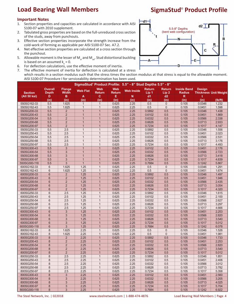
SigmaStud® Product Profile: 5.5” - 8” Stud Depths 5.5” - 8”
Section(All 50 ksi)
Overall Depth
Flange Width Web Flat Web
ReturnWeb
Return Web Inside Return Lip 1
Return Lip 2
Inside Bend Radius
Design Thickness Unit Weight
D B A C E N d1 d2 R t(in) (in) (in) (in) (in) (in) (in) (in) (in) (in) (lb/ft)
550SG162-33 5.5 1.625 1 1 0.625 2.25 0.5 0 0.105 0.0346 1.232550SG162-43 5.5 1.625 1 1 0.625 2.25 0.5 0 0.105 0.0451 1.598550SG200-33 5.5 2 1 1 0.625 2.25 0.5892 0.5 0.105 0.0346 1.438550SG200-43 5.5 2 1 1 0.625 2.25 0.6102 0.5 0.105 0.0451 1.869550SG200-54 5.5 2 1 1 0.625 2.25 0.6332 0.5 0.105 0.0566 2.338550SG200-68 5.5 2 1 1 0.625 2.25 0.6626 0.5 0.105 0.0713 2.933550SG200-97 5.5 2 1 1 0.625 2.25 0.7234 0.5 0.105 0.1017 4.147550SG250-33 5.5 2.5 1 1 0.625 2.25 0.5892 0.5 0.105 0.0346 1.556550SG250-43 5.5 2.5 1 1 0.625 2.25 0.6102 0.5 0.105 0.0451 2.023550SG250-54 5.5 2.5 1 1 0.625 2.25 0.6332 0.5 0.105 0.0566 2.531550SG250-68 5.5 2.5 1 1 0.625 2.25 0.6626 0.5 0.105 0.0713 3.176550SG250-97 5.5 2.5 1 1 0.625 2.25 0.7234 0.5 0.105 0.1017 4.493550SG300-43 5.5 3 1 1 0.625 2.25 0.6102 0.5 0.105 0.0451 2.176550SG300-54 5.5 3 1 1 0.625 2.25 0.6332 0.5 0.105 0.0566 2.723550SG300-68 5.5 3 1 1 0.625 2.25 0.6626 0.5 0.105 0.0713 3.418550SG300-97 5.5 3 1 1 0.625 2.25 0.7234 0.5 0.105 0.1017 4.839550SG300-118 5.5 3 1 1 0.625 2.25 0.7684 0.5 0.105 0.1242 5.867600SG162-33 6 1.625 1.25 1 0.625 2.25 0.5 0 0.105 0.0346 1.291600SG162-43 6 1.625 1.25 1 0.625 2.25 0.5 0 0.105 0.0451 1.674600SG200-33 6 2 1.25 1 0.625 2.25 0.5892 0.5 0.105 0.0346 1.497600SG200-43 6 2 1.25 1 0.625 2.25 0.6102 0.5 0.105 0.0451 1.946600SG200-54 6 2 1.25 1 0.625 2.25 0.6332 0.5 0.105 0.0566 2.435600SG200-68 6 2 1.25 1 0.625 2.25 0.6626 0.5 0.105 0.0713 3.054600SG200-97 6 2 1.25 1 0.625 2.25 0.7234 0.5 0.105 0.1017 4.320600SG250-33 6 2.5 1.25 1 0.625 2.25 0.5892 0.5 0.105 0.0346 1.615600SG250-43 6 2.5 1.25 1 0.625 2.25 0.6102 0.5 0.105 0.0451 2.100600SG250-54 6 2.5 1.25 1 0.625 2.25 0.6332 0.5 0.105 0.0566 2.627600SG250-68 6 2.5 1.25 1 0.625 2.25 0.6626 0.5 0.105 0.0713 3.297600SG250-97 6 2.5 1.25 1 0.625 2.25 0.7234 0.5 0.105 0.1017 4.666600SG300-43 6 3 1.25 1 0.625 2.25 0.6102 0.5 0.105 0.0451 2.253600SG300-54 6 3 1.25 1 0.625 2.25 0.6332 0.5 0.105 0.0566 2.820600SG300-68 6 3 1.25 1 0.625 2.25 0.6626 0.5 0.105 0.0713 3.540600SG300-97 6 3 1.25 1 0.625 2.25 0.7234 0.5 0.105 0.1017 5.012600SG300-118 6 3 1.25 1 0.625 2.25 0.7684 0.5 0.105 0.1242 6.078800SG162-33 8 1.625 2.25 1 0.625 2.25 0.5 0 0.105 0.0346 1.526800SG162-43 8 1.625 2.25 1 0.625 2.25 0.5 0 0.105 0.0451 1.981800SG200-33 8 2 2.25 1 0.625 2.25 0.5892 0.5 0.105 0.0346 1.733800SG200-43 8 2 2.25 1 0.625 2.25 0.6102 0.5 0.105 0.0451 2.253800SG200-54 8 2 2.25 1 0.625 2.25 0.6332 0.5 0.105 0.0566 2.820800SG200-68 8 2 2.25 1 0.625 2.25 0.6626 0.5 0.105 0.0713 3.540800SG200-97 8 2 2.25 1 0.625 2.25 0.7234 0.5 0.105 0.1017 5.012800SG250-33 8 2.5 2.25 1 0.625 2.25 0.5892 0.5 0.105 0.0346 1.851800SG250-43 8 2.5 2.25 1 0.625 2.25 0.6102 0.5 0.105 0.0451 2.406800SG250-54 8 2.5 2.25 1 0.625 2.25 0.6332 0.5 0.105 0.0566 3.012800SG250-68 8 2.5 2.25 1 0.625 2.25 0.6626 0.5 0.105 0.0713 3.782800SG250-97 8 2.5 2.25 1 0.625 2.25 0.7234 0.5 0.105 0.1017 5.358800SG300-43 8 3 2.25 1 0.625 2.25 0.6102 0.5 0.105 0.0451 2.560800SG300-54 8 3 2.25 1 0.625 2.25 0.6332 0.5 0.105 0.0566 3.205800SG300-68 8 3 2.25 1 0.625 2.25 0.6626 0.5 0.105 0.0713 4.025800SG300-97 8 3 2.25 1 0.625 2.25 0.7234 0.5 0.105 0.1017 5.704800SG300-118 8 3 2.25 1 0.625 2.25 0.7684 0.5 0.105 0.1242 6.922
5.5-8" Depths(bent web configuration)
Important Notes1. Section properties and capacities are calculated in accordance with AISI
S100-07 with 2010 supplement.2. Tabulated gross properties are based on the full-unreduced cross section
of the studs, away from punchouts.3. Effective section properties incorporate the strength increase from the
cold-work of forming as applicable per AISI S100-07 Sec. A7.2.4. Net effective section properties are calculated at a cross section through
the punchout.5. Allowable moment is the lesser of Mal and Mad. Stud distortional buckling
is based on an assumed k = 0.6. For deflection calculations, use the effective moment of inertia.7. The effective moment of inertia for deflection is calculated at a stress
which results in a section modulus such that the stress times the section modulus at that stress is equal to the allowable moment. AISI S100-07 Procedure I for serviceability determination has been used.
Load Bearing Wall Members

022018 | The Steel Network, Inc.www.steelnetwork.com | 1-888-474-4876Page | Load Bearing Wall Members 5
SigmaStud® Section Properties
SigmaStud® Section Properties
Section(All 50 ksi)
Gross Properties Torsional Properties Eff ective Properties 50 ksiArea Ix Sx Rx Iy Ry Jx103 Cw Ro Xo m
ßAe (net) Ix Sx Sx (net) Mal Mal (net) Mad Va Va (net)
(in2) (in4) (in3) (in) (in4) (in) (in4) (in6) (in) (in) (in) (in2) (in4) (in3) (in3) (kips-in) (kips-in) (kips-in) (lbs) (lbs)
350SG200-33 0.317 0.630 0.360 1.410 0.194 0.782 0.126 0.718 2.549 -1.975 1.178 0.400 0.201 0.615 0.310 0.283 9.295 8.479 8.570 1145 527
350SG200-43 0.411 0.810 0.463 1.404 0.249 0.779 0.279 0.929 2.541 -1.969 1.176 0.399 0.293 0.810 0.430 0.406 12.878 12.161 12.176 2141 747
350SG200-54 0.514 1.003 0.573 1.397 0.309 0.775 0.549 1.158 2.531 -1.963 1.173 0.398 0.384 1.003 0.550 0.530 16.470 15.871 16.295 3371 925
350SG200-68 0.644 1.241 0.709 1.388 0.382 0.770 1.091 1.444 2.519 -1.955 1.169 0.397 0.529 1.241 0.709 0.696 23.531 20.831 21.230 4208 900
350SG200-97 0.909 1.705 0.974 1.370 0.525 0.760 3.132 2.017 2.492 -1.938 1.160 0.395 0.756 1.705 0.974 0.958 33.387 32.831 29.168 5886 850
350SG250-33 0.351 0.734 0.419 1.445 0.329 0.967 0.140 1.206 3.025 -2.476 1.448 0.330 0.210 0.692 0.331 0.300 9.904 8.995 9.106 1145 527
350SG250-43 0.456 0.945 0.540 1.439 0.424 0.964 0.309 1.565 3.017 -2.471 1.445 0.329 0.292 0.933 0.447 0.418 13.371 12.505 13.045 2141 747
350SG250-54 0.571 1.171 0.669 1.432 0.526 0.960 0.609 1.953 3.008 -2.465 1.442 0.329 0.383 1.171 0.571 0.545 17.099 16.324 17.616 3371 925
350SG250-68 0.715 1.450 0.829 1.424 0.653 0.955 1.212 2.443 2.996 -2.457 1.439 0.328 0.519 1.450 0.748 0.728 22.400 21.809 23.676 4208 900
350SG250-97 1.010 1.999 1.142 1.406 0.904 0.946 3.483 3.431 2.972 -2.441 1.430 0.325 0.858 1.999 1.125 1.107 37.597 37.006 34.192 5886 850
350SG350-68 0.858 1.870 1.068 1.476 1.471 1.309 1.454 5.401 3.980 -3.456 1.965 0.246 0.535 1.812 0.804 0.774 24.073 23.179 26.651 4208 900
362SG200-33 0.321 0.683 0.377 1.459 0.196 0.782 0.128 0.759 2.561 -1.954 1.168 0.418 0.202 0.667 0.326 0.295 9.754 8.842 8.919 1102 544
362SG200-43 0.417 0.879 0.485 1.452 0.253 0.779 0.283 0.983 2.552 -1.948 1.166 0.417 0.293 0.879 0.451 0.424 13.504 12.690 12.685 2141 802
362SG200-54 0.521 1.089 0.601 1.445 0.313 0.775 0.556 1.224 2.542 -1.942 1.163 0.416 0.385 1.089 0.577 0.553 17.261 16.571 16.994 3372 994
362SG200-68 0.653 1.348 0.744 1.437 0.388 0.770 1.107 1.526 2.530 -1.934 1.159 0.415 0.532 1.348 0.744 0.728 24.678 21.799 22.265 4375 1007
362SG200-97 0.921 1.854 1.023 1.419 0.533 0.761 3.176 2.130 2.504 -1.918 1.150 0.413 0.769 1.854 1.023 1.007 35.050 34.514 30.621 6124 954
362SG250-33 0.356 0.795 0.438 1.495 0.333 0.968 0.142 1.277 3.031 -2.453 1.437 0.345 0.210 0.750 0.347 0.313 10.387 9.375 9.461 1102 544
362SG250-43 0.462 1.024 0.565 1.489 0.430 0.964 0.313 1.656 3.023 -2.447 1.435 0.344 0.293 1.011 0.468 0.435 14.012 13.038 13.565 2141 802
362SG250-54 0.578 1.269 0.700 1.482 0.533 0.961 0.617 2.066 3.014 -2.442 1.432 0.344 0.385 1.269 0.598 0.569 17.908 17.031 18.335 3372 994
362SG250-68 0.724 1.573 0.868 1.474 0.662 0.956 1.227 2.583 3.002 -2.434 1.428 0.342 0.522 1.573 0.783 0.761 23.449 22.775 24.670 4375 1007
362SG250-97 1.023 2.169 1.197 1.456 0.916 0.946 3.527 3.625 2.977 -2.418 1.420 0.340 0.870 2.169 1.178 1.161 39.389 38.814 35.835 6124 954
362SG350-68 0.867 2.023 1.116 1.528 1.491 1.311 1.469 5.715 3.977 -3.430 1.954 0.256 0.538 1.961 0.841 0.808 25.186 24.190 27.689 4375 1007
400SG200-33 0.334 0.859 0.429 1.603 0.204 0.782 0.133 0.895 2.602 -1.894 1.139 0.470 0.202 0.840 0.373 0.332 11.168 9.928 9.971 991 589
400SG200-43 0.434 1.107 0.553 1.597 0.263 0.778 0.294 1.157 2.593 -1.889 1.136 0.469 0.295 1.107 0.515 0.477 15.429 14.276 14.220 2141 967
400SG200-54 0.542 1.371 0.686 1.590 0.325 0.775 0.579 1.440 2.583 -1.883 1.133 0.469 0.389 1.371 0.658 0.624 19.693 18.673 19.109 3372 1201
400SG200-68 0.680 1.700 0.850 1.581 0.403 0.770 1.152 1.794 2.571 -1.875 1.129 0.468 0.540 1.700 0.850 0.825 28.202 24.708 25.444 4876 1360
400SG200-97 0.959 2.344 1.172 1.563 0.555 0.760 3.308 2.498 2.544 -1.858 1.121 0.467 0.806 2.344 1.172 1.158 40.162 34.664 35.087 6839 1299
400SG250-33 0.369 0.995 0.497 1.643 0.346 0.969 0.147 1.506 3.055 -2.386 1.407 0.390 0.211 0.941 0.397 0.351 11.873 10.514 10.530 991 589
400SG250-43 0.479 1.283 0.641 1.637 0.446 0.965 0.325 1.951 3.046 -2.381 1.404 0.389 0.294 1.268 0.534 0.489 15.981 14.635 15.133 2141 967
400SG250-54 0.599 1.591 0.796 1.630 0.554 0.962 0.640 2.432 3.037 -2.375 1.401 0.388 0.388 1.591 0.681 0.640 20.397 19.150 20.506 3372 1201
400SG250-68 0.751 1.975 0.987 1.622 0.688 0.957 1.273 3.038 3.025 -2.368 1.398 0.387 0.530 1.975 0.891 0.858 26.669 25.675 27.679 4876 1360
400SG250-97 1.061 2.730 1.365 1.604 0.953 0.948 3.658 4.255 3.000 -2.352 1.390 0.386 0.908 2.730 1.343 1.351 44.884 40.448 40.871 6839 1299
400SG350-68 0.894 2.525 1.263 1.681 1.547 1.316 1.514 6.736 3.976 -3.354 1.922 0.288 0.545 2.447 0.955 0.909 28.602 27.223 30.818 4876 1360
400SG350-97 1.265 3.503 1.751 1.664 2.158 1.306 4.360 9.488 3.953 -3.339 1.915 0.286 0.917 3.483 1.502 1.473 44.961 44.092 49.104 6839 1299
400SG350-118 1.533 4.184 2.092 1.652 2.587 1.299 7.855 11.458 3.936 -3.328 1.909 0.285 1.235 4.184 1.980 1.955 59.268 58.533 62.640 8235 1256
Important Notes1. Section properties and capacities are calculated in accordance with AISI S100-07 with 2010 supplement.2. Tabulated gross properties are based on the full-unreduced cross section of the studs, away from punchouts.3. Effective section properties incorporate the strength increase from the cold-work of forming as applicable per AISI S100-07 Sec. A7.2.4. Net effective section properties are calculated at a cross section through the punchout.5. Allowable moment is the lesser of Mal and Mad. Stud distortional buckling is based on an assumed k = 0.6. For deflection calculations, use the effective moment of inertia.7. The effective moment of inertia for deflection is calculated at a stress which results in a section modulus such that the stress times
the section modulus at that stress is equal to the allowable moment. AISI S100-07 Procedure I for serviceability determination has been used.
Load Bearing Wall Members

The Steel Network, Inc. | 022018 www.steelnetwork.com | 1-888-474-4876 Load Bearing Wall Members | Page 6
SigmaStud® Section PropertiesRefer to Important Table Notes on Page 5
SigmaStud® Section Properties
Section(All 50 ksi)
Gross Properties Torsional Properties Eff ective Properties 50 ksiArea Ix Sx Rx Iy Ry Jx103 Cw Ro Xo m
ßAe (net) Ix Sx Sx (net) Mal Mal (net) Mad Va Va (net)
(in2) (in4) (in3) (in) (in4) (in) (in4) (in6) (in) (in) (in) (in2) (in4) (in3) (in3) (kips-in) (kips-in) (kips-in) (lbs) (lbs)550SG162-33 0.362 1.522 0.554 2.051 0.096 0.514 0.144 0.864 2.124 -0.203 0.495 0.991 0.261 1.522 0.498 0.492 14.920 14.716 11.731 997 587550SG162-43 0.469 1.963 0.714 2.045 0.122 0.510 0.318 1.097 2.116 -0.191 0.504 0.992 0.364 1.963 0.663 0.655 19.843 19.611 16.926 2141 952550SG200-33 0.423 1.882 0.684 2.110 0.175 0.643 0.169 1.783 2.319 -0.716 0.160 0.905 0.315 1.855 0.609 0.602 18.234 18.016 14.840 997 587550SG200-43 0.549 2.432 0.884 2.104 0.225 0.640 0.372 2.294 2.310 -0.708 0.165 0.906 0.447 2.432 0.833 0.826 24.934 24.718 21.359 2141 952550SG200-54 0.687 3.023 1.099 2.097 0.278 0.636 0.734 2.838 2.301 -0.700 0.172 0.907 0.577 3.023 1.058 1.050 31.665 31.425 28.982 3372 1176550SG200-68 0.862 3.761 1.368 2.089 0.344 0.631 1.460 3.510 2.289 -0.689 0.180 0.909 0.755 3.761 1.368 1.361 45.387 45.149 39.170 4793 1298550SG200-97 1.219 5.229 1.901 2.072 0.471 0.622 4.201 4.816 2.263 -0.667 0.197 0.913 1.066 5.229 1.901 1.891 65.164 64.815 56.931 6657 1207550SG250-33 0.457 2.140 0.778 2.163 0.302 0.813 0.182 2.936 2.584 -1.157 0.109 0.800 0.324 2.051 0.644 0.634 19.272 18.975 15.414 997 587550SG250-43 0.594 2.767 1.006 2.158 0.389 0.809 0.403 3.788 2.575 -1.149 0.104 0.801 0.446 2.744 0.860 0.848 25.735 25.384 22.319 2141 952550SG250-54 0.744 3.442 1.252 2.151 0.483 0.806 0.794 4.701 2.565 -1.141 0.098 0.802 0.576 3.442 1.092 1.078 32.686 32.274 30.488 3372 1176550SG250-68 0.933 4.286 1.559 2.143 0.599 0.801 1.581 5.835 2.552 -1.131 0.090 0.804 0.745 4.286 1.418 1.403 42.443 42.007 41.569 4793 1298550SG250-97 1.320 5.970 2.171 2.126 0.826 0.791 4.552 8.069 2.525 -1.108 0.073 0.807 1.168 5.970 2.133 2.121 71.321 70.907 64.998 6657 1207550SG300-43 0.639 3.103 1.128 2.203 0.622 0.987 0.434 5.742 2.894 -1.597 0.369 0.695 0.443 2.984 0.876 0.859 26.214 25.729 23.034 2141 952550SG300-54 0.800 3.861 1.404 2.197 0.773 0.983 0.855 7.139 2.884 -1.589 0.363 0.696 0.580 3.725 1.128 1.110 33.781 33.222 31.625 3372 1176550SG300-68 1.004 4.812 1.750 2.189 0.960 0.978 1.702 8.883 2.870 -1.579 0.355 0.697 0.756 4.753 1.476 1.455 44.180 43.572 43.406 4793 1298550SG300-97 1.422 6.711 2.440 2.172 1.332 0.968 4.902 12.348 2.843 -1.557 0.340 0.700 1.187 6.711 2.310 2.293 69.159 68.650 69.483 6657 1207550SG300-118 1.724 8.048 2.927 2.161 1.590 0.960 8.837 14.766 2.822 -1.541 0.328 0.702 1.486 8.048 2.812 2.793 93.863 93.245 87.622 7956 1142600SG162-33 0.379 1.854 0.618 2.211 0.104 0.523 0.151 1.090 2.284 -0.234 0.432 0.990 0.279 1.854 0.558 0.551 16.702 16.505 12.720 878 634600SG162-43 0.492 2.392 0.797 2.205 0.133 0.519 0.334 1.386 2.276 -0.222 0.441 0.990 0.386 2.392 0.741 0.734 22.192 21.969 18.413 1959 1073600SG200-33 0.440 2.291 0.764 2.282 0.187 0.653 0.176 2.203 2.487 -0.744 0.097 0.910 0.333 2.262 0.682 0.675 20.417 20.203 16.201 878 634600SG200-43 0.572 2.962 0.987 2.276 0.241 0.650 0.388 2.837 2.479 -0.737 0.102 0.912 0.470 2.962 0.931 0.924 27.880 27.673 23.374 1959 1073600SG200-54 0.715 3.683 1.228 2.269 0.299 0.646 0.764 3.513 2.469 -0.729 0.108 0.913 0.605 3.683 1.182 1.174 35.379 35.150 31.797 3372 1451600SG200-68 0.898 4.586 1.529 2.261 0.370 0.642 1.521 4.350 2.457 -0.719 0.116 0.914 0.791 4.586 1.529 1.522 50.735 50.518 43.111 5350 1796600SG200-97 1.269 6.386 2.129 2.243 0.508 0.633 4.376 5.980 2.432 -0.697 0.133 0.918 1.117 6.386 2.129 2.119 72.948 72.629 63.731 7610 1726600SG250-33 0.475 2.599 0.866 2.340 0.320 0.822 0.189 3.590 2.747 -1.180 0.170 0.815 0.341 2.496 0.720 0.710 21.563 21.269 16.810 878 634600SG250-43 0.617 3.362 1.121 2.334 0.413 0.818 0.418 4.633 2.737 -1.173 0.165 0.816 0.469 3.339 0.961 0.949 28.760 28.412 24.389 1959 1073600SG250-54 0.772 4.183 1.394 2.328 0.513 0.815 0.824 5.752 2.728 -1.165 0.160 0.818 0.604 4.183 1.219 1.206 36.501 36.093 33.384 3372 1451600SG250-68 0.969 5.213 1.738 2.320 0.636 0.810 1.642 7.145 2.715 -1.155 0.152 0.819 0.780 5.213 1.582 1.567 47.351 46.922 45.633 5350 1796600SG250-97 1.371 7.270 2.423 2.303 0.879 0.800 4.727 9.893 2.688 -1.133 0.137 0.822 1.219 7.270 2.381 2.369 79.592 79.202 72.361 7610 1726600SG300-43 0.662 3.761 1.254 2.384 0.655 0.995 0.449 6.972 3.047 -1.616 0.429 0.719 0.466 3.628 0.979 0.962 29.297 28.809 25.131 1959 1073600SG300-54 0.829 4.683 1.561 2.377 0.814 0.991 0.885 8.670 3.036 -1.608 0.424 0.720 0.608 4.526 1.260 1.241 37.713 37.153 34.564 3372 1451600SG300-68 1.040 5.840 1.947 2.369 1.012 0.986 1.763 10.793 3.023 -1.598 0.417 0.721 0.791 5.775 1.646 1.625 49.272 48.663 47.543 5350 1796600SG300-97 1.473 8.155 2.718 2.353 1.404 0.976 5.078 15.015 2.996 -1.577 0.402 0.723 1.238 8.155 2.572 2.556 77.021 76.525 76.434 7610 1726600SG300-118 1.786 9.789 3.263 2.341 1.678 0.969 9.154 17.967 2.976 -1.562 0.391 0.725 1.548 9.789 3.134 3.116 104.620 104.024 97.696 9118 1649800SG162-33 0.448 3.631 0.908 2.845 0.130 0.538 0.179 2.193 2.912 -0.302 0.261 0.989 0.298 3.631 0.754 0.744 22.576 22.270 16.445 595 595800SG162-43 0.582 4.691 1.173 2.839 0.166 0.534 0.395 2.796 2.903 -0.292 0.269 0.990 0.439 4.691 1.056 1.047 31.604 31.335 24.107 1324 1269800SG200-33 0.509 4.453 1.113 2.957 0.230 0.672 0.203 4.278 3.134 -0.791 0.064 0.936 0.352 4.422 0.930 0.919 27.843 27.525 21.591 595 595800SG200-43 0.662 5.765 1.441 2.951 0.296 0.669 0.449 5.516 3.126 -0.784 0.059 0.937 0.522 5.765 1.325 1.317 39.673 39.425 31.423 1324 1269800SG200-54 0.829 7.181 1.795 2.944 0.367 0.666 0.885 6.840 3.117 -0.777 0.054 0.938 0.701 7.181 1.731 1.724 51.819 51.620 43.141 2632 1994800SG200-68 1.040 8.960 2.240 2.935 0.455 0.662 1.763 8.484 3.105 -0.767 0.047 0.939 0.933 8.960 2.240 2.235 74.340 74.180 59.159 5301 3157800SG200-97 1.473 12.530 3.133 2.917 0.629 0.653 5.078 11.713 3.081 -0.748 0.033 0.941 1.320 12.530 3.133 3.126 107.352 107.117 93.788 10885 4451800SG250-33 0.544 5.002 1.250 3.033 0.382 0.838 0.217 6.837 3.368 -1.202 0.321 0.873 0.360 4.848 0.980 0.967 29.352 28.942 22.427 595 595800SG250-43 0.707 6.478 1.620 3.027 0.493 0.835 0.479 8.833 3.360 -1.196 0.317 0.873 0.522 6.468 1.363 1.349 40.806 40.395 32.761 1324 1269800SG250-54 0.885 8.074 2.019 3.020 0.612 0.832 0.945 10.975 3.350 -1.189 0.312 0.874 0.701 8.074 1.782 1.769 53.363 52.965 45.165 2632 1994800SG250-68 1.111 10.081 2.520 3.012 0.761 0.827 1.883 13.649 3.339 -1.179 0.305 0.875 0.923 10.081 2.304 2.291 68.996 68.586 62.282 5301 3157800SG250-97 1.575 14.116 3.529 2.994 1.055 0.818 5.428 18.950 3.314 -1.160 0.292 0.877 1.422 14.116 3.466 3.456 115.861 115.535 100.510 10885 4451800SG300-43 0.752 7.192 1.798 3.092 0.767 1.010 0.510 13.119 3.633 -1.617 0.573 0.802 0.518 7.010 1.387 1.368 41.519 40.945 33.663 1324 1269800SG300-54 0.942 8.967 2.242 3.086 0.954 1.006 1.006 16.324 3.623 -1.610 0.568 0.802 0.705 8.758 1.839 1.820 55.068 54.497 46.575 2632 1994800SG300-68 1.183 11.202 2.800 3.078 1.187 1.002 2.004 20.337 3.611 -1.601 0.562 0.803 0.934 11.142 2.394 2.373 71.673 71.061 64.531 5301 3157800SG300-97 1.676 15.702 3.926 3.061 1.651 0.993 5.779 28.342 3.586 -1.582 0.549 0.805 1.441 15.702 3.719 3.703 111.337 110.877 105.253 10885 4451800SG300-118 2.034 18.902 4.725 3.048 1.976 0.986 10.426 33.962 3.567 -1.568 0.540 0.807 1.796 18.902 4.539 4.523 151.547 151.009 136.886 13768 4546
Load Bearing Wall Members

022018 | The Steel Network, Inc.www.steelnetwork.com | 1-888-474-4876Page | Load Bearing Wall Members 7
Table Notes & ExamplesTable Background And Example1. Basis For Tables:The SigmaStud Combined Axial and Lateral Load tables in this catalog cover the following basic load combina ons for the Allowable Stress Design (ASD) Method (IBC 2009/2012 and ASCE 7-05/10). Listed wind pressures represent calculated design wind pressure (1.0W based on 2009 or 0.6W based on 2012 IBC). • IBC 2009 / ASCE 7-05 i. D + L (Strength Determina on) ii. D + 0.75L + 0.75WMWFRS* (Strength Determina on) iii. 0.70WC&C** (Defl ec on Determina on) • IBC 2012 / ASCE 7-10 i. D + L (Strength Determina on) ii. D + 0.75L + 0.75(0.6WMWFRS*) (Strength Determina on) iii. D + 0.70(0.6WC&C**) (Defl ec on Determina on)* MWFRS: Main Wind Force Resis ng System** C&C: Component and Cladding- For defl ec on determina on IBC 2009 and IBC 2012 Sec. 1604.3 and AISI S211-07 Wall Stud Design Standard Sec. A3.1 allows for a reduc on factor of 0.7 on the component and cladding wind load (0.7WC&C).&C).2. Design Example:Given:Service (Un-factored) Loads: Axial Dead Load = 1.6 kips Axial Live Load = 3.2 kips Wind Pressure (WMWFRS)(ASCE 7-05)
OR (0.6WMWFRS)(ASCE 7-10) = 28 psf Wind Pressure (WC&C)(ASCE 7-05)
OR (0.6WC&C)(ASCE 7-10) = 40 psf Wall Width = 6 in. Stud Height = 12 ft. Stud Spacing = 16 in. o.c. Specified Deflection Limit = L/360 Bridging (Lateral Bracing) at maximum vertical spacing of 48” o.c.Calculations:
a) Use the D + L load combination to get the first estimate of the stud. Combination total axial load = 1.6 kips + 3.2 kips = 4.8 kips From the “No Lateral Load” table with a 12 ft wall height, choose 600SG200-43 (50 ksi) with an axial resistance of 9.35 kips > 4.8 kips. OK
b) Check the D + 0.75L + 0.75WMWFRS (IBC 2009 / ASCE 7-05) OR D + 0.75L + 0.75(0.6WMWFRS) (IBC 2012 / ASCE 7-10) load combination for strength. Combination total axial load = 1.6 kips + 0.75(3.2 kips) = 4.0 kips 0.75WMWFRS OR 0.75(0.6WMWFRS) = 0.75 x 28 psf = 21 psf (approximately 20 psf) Go to the “Lateral Load = 20 psf” table with a 12 ft. wall height and 16 in. stud spacing. The axial resistance for 600SG200-43 (50 ksi) is 6.20 kips > 4.0 kips. OK
c) Check the 0.70WC&C (IBC 2009 / ASCE 7-05) OR 0.70(0.6WC&C) (IBC 2012 / ASCE 7-10) load combination for deflection. The specified limit is L/360. Go to the “Lateral Load = 40 psf” table with a 12 ft. wall height and 16 in. stud spacing. The deflection parameter for 600SG200-43 (50 ksi) is blank, which indicates that deflection is less than L/720 < L/360. OKConclusion:
Use 600SG200-43 (50 ksi) (with design thickness = 0.0451” and Fy = 50 ksi) spaced at 16 in. o.c. with 2 lines of bridging arranged so that the maximum spacing does not exceed 48 in. (4 ft.)
3. Extra Design Considerations: a) Check lateral end reaction of the stud for web crippling if applicable. b) If the specified axial dead load acting on the stud is significantly larger than the specified axial live load, the following basic load combination needs to be checked as well: • IBC 2009 / ASCE 7-05 i. D + WC&C (Strength Determination) • IBC 2012 / ASCE 7-10 i. D + (0.6WC&C) (Strength Determination)
Load Bearing Wall Members

The Steel Network, Inc. | 022018 www.steelnetwork.com | 1-888-474-4876 Load Bearing Wall Members | Page 8
Important Notes1. Allowable loads are based on weak axis and torsional bracing at 48" o.c. maximum for axial load calculation and continuous support
of each flange for flexural calculation.2. Sections are punched with a standard punch-out 1.5" wide located along the centerline of the web 24" o.c. 3. Allowable loads are based on checks for punched section under axial load, flexural, and shear conditions.4. Weak axis and torsional bracing should have sufficient stiffness and strength to resist the axial load.5. The allowable axial strength for distortional buckling is based on an assumed k = 0.6. Strength increase due to cold forming is incorporated in calculating allowable loads as per AISI Specification Sec. A7.2.7. Contact The Steel Network if web crippling capacity values of SigmaStud® are required to check lateral end reactions.8. Loads in tables are in kips/stud.
Combined Axial & Lateral Load Tables
No Lateral Load (For Load Combination 1.0 [D+L]): Axial Compression Load (kips)Wall
Height (ft)Spacing (in) o.c.
350SG200-(mils) 350SG250-(mils) 350SG350-(mils) 362SG200-(mils)33 43 54 68 97 33 43 54 68 97 68 33 43 54 68 97
8 12, 16, 24 3.21 4.54 5.88 7.43 10.68 3.46 5.09 6.80 8.58 12.25 9.22 3.31 4.72 6.12 7.83 11.249 12, 16, 24 3.02 4.23 5.45 6.87 9.83 3.27 4.80 6.32 7.94 11.30 8.76 3.14 4.42 5.73 7.28 10.4210 12, 16, 24 2.82 3.89 4.98 6.26 8.93 3.06 4.48 5.78 7.26 10.31 8.33 2.94 4.10 5.30 6.69 9.5412 12, 16, 24 2.37 3.19 4.02 5.03 7.12 2.61 3.72 4.69 5.87 8.28 7.20 2.51 3.40 4.34 5.44 7.7014 12, 16, 24 1.95 2.60 3.23 4.04 5.67 2.22 3.04 3.78 4.72 6.62 6.06 2.07 2.79 3.50 4.38 6.1516 12, 16, 24 1.61 2.12 2.63 3.28 4.58 1.89 2.48 3.09 3.85 5.37 4.96 1.72 2.30 2.86 3.56 4.97
Wall Height (ft)
Spacing (in) o.c.
362SG250-(mils) 362SG350-(mils) 400SG200-(mils) 400SG250-(mils)
33 43 54 68 97 68 33 43 54 68 97 33 43 54 68 97
8 12, 16, 24 3.57 5.27 7.08 9.03 12.89 9.62 3.58 5.19 6.76 8.85 12.86 3.86 5.69 7.61 10.18 14.72
9 12, 16, 24 3.39 4.98 6.62 8.41 11.96 9.12 3.43 4.93 6.42 8.39 12.11 3.70 5.47 7.35 9.65 13.87
10 12, 16, 24 3.19 4.68 6.13 7.74 10.99 8.69 3.26 4.64 6.04 7.88 11.29 3.53 5.20 6.99 9.07 12.95
12 12, 16, 24 2.75 3.97 5.07 6.34 8.95 7.67 2.88 4.01 5.20 6.73 9.52 3.14 4.60 6.03 7.78 10.99
14 12, 16, 24 2.34 3.26 4.09 5.11 7.17 6.54 2.47 3.34 4.33 5.49 7.73 2.71 3.91 5.04 6.39 8.98
16 12, 16, 24 2.00 2.69 3.34 4.17 5.82 5.36 2.06 2.78 3.59 4.48 6.28 2.33 3.25 4.18 5.23 7.31
Wall Height (ft)
Spacing (in) o.c.
400SG350-(mils) 550SG162-(mils) 550SG200-(mils) 550SG250-(mils) 550SG300-(mils)68 97 118 33 43 33 43 54 68 97 33 43 54 68 97 43 54 68 97 118
8 12, 16, 24 10.60 17.25 22.17 4.60 5.91 6.49 8.83 11.11 13.84 19.30 6.59 9.86 12.94 17.12 24.89 9.84 13.41 17.44 27.06 34.19
9 12, 16, 24 10.20 16.45 20.91 4.60 5.91 6.49 8.83 11.11 13.84 19.30 6.59 9.86 12.94 17.12 24.89 9.84 13.10 17.02 26.40 33.18
10 12, 16, 24 9.75 15.62 19.56 4.60 5.91 6.49 8.83 11.11 13.84 19.30 6.59 9.86 12.59 16.72 24.33 9.84 12.74 16.54 25.65 31.99
12 12, 16, 24 8.87 13.80 16.69 4.60 5.91 6.49 8.83 11.11 13.84 19.30 6.59 9.33 11.70 15.62 22.22 9.31 11.88 15.42 23.95 29.25
14 12, 16, 24 7.79 11.41 13.76 4.60 5.91 6.00 8.17 10.22 12.79 17.96 6.23 8.54 10.78 14.10 19.83 8.56 10.90 14.30 21.67 26.18
16 12, 16, 24 6.68 9.35 11.25 4.56 5.89 5.31 7.15 8.91 11.13 15.59 5.56 7.67 9.83 12.36 17.34 7.75 9.83 13.00 19.06 22.99
Wall Height (ft)
Spacing (in) o.c.
600SG162-(mils) 600SG200-(mils) 600SG250-(mils) 600SG300-(mils)
33 43 33 43 54 68 97 33 43 54 68 97 43 54 68 97 118
8 12, 16, 24 4.47 6.38 6.39 9.35 11.78 14.69 20.51 6.52 9.78 13.61 17.97 26.14 9.80 13.87 18.60 28.77 36.43
9 12, 16, 24 4.47 6.38 6.39 9.35 11.78 14.69 20.51 6.52 9.78 13.61 17.97 26.14 9.80 13.87 18.24 28.19 35.56
10 12, 16, 24 4.47 6.38 6.39 9.35 11.78 14.69 20.51 6.52 9.78 13.56 17.95 26.14 9.80 13.73 17.81 27.51 34.52
12 12, 16, 24 4.47 6.38 6.39 9.35 11.78 14.69 20.51 6.52 9.78 12.76 16.94 24.38 9.80 12.95 16.77 25.92 32.03
14 12, 16, 24 4.47 6.38 6.39 9.09 11.45 14.33 20.17 6.52 9.43 11.80 15.73 22.16 9.44 12.03 15.64 24.14 29.18
16 12, 16, 24 4.47 6.38 6.02 8.17 10.19 12.74 17.89 6.29 8.61 10.94 14.07 19.78 8.67 11.02 14.50 21.65 26.14
Wall Height (ft)
Spacing (in) o.c.
800SG162-(mils) 800SG200-(mils) 800SG250-(mils) 800SG300-(mils)
33 43 33 43 54 68 97 33 43 54 68 97 43 54 68 97 118
8 12, 16, 24 3.63 5.50 5.70 8.62 12.28 17.53 24.88 6.04 9.15 13.03 18.62 30.85 9.39 13.40 19.19 33.05 43.29
9 12, 16, 24 3.63 5.50 5.70 8.62 12.28 17.53 24.88 6.04 9.15 13.03 18.62 30.85 9.39 13.40 19.19 33.05 43.29
10 12, 16, 24 3.63 5.50 5.70 8.62 12.28 17.53 24.88 6.04 9.15 13.03 18.62 30.85 9.39 13.40 19.19 33.05 43.29
12 12, 16, 24 3.63 5.50 5.70 8.62 12.28 17.53 24.88 6.04 9.15 13.03 18.62 30.85 9.39 13.40 19.19 33.05 41.77
14 12, 16, 24 3.63 5.50 5.70 8.62 12.28 17.53 24.88 6.04 9.15 13.03 18.62 30.40 9.39 13.40 19.19 31.82 39.70
16 12, 16, 24 3.63 5.50 5.70 8.62 12.28 17.53 24.88 6.04 9.15 13.03 18.62 28.52 9.39 13.40 19.19 30.21 37.29
Load Bearing Wall Members

022018 | The Steel Network, Inc.www.steelnetwork.com | 1-888-474-4876Page | Load Bearing Wall Members 9
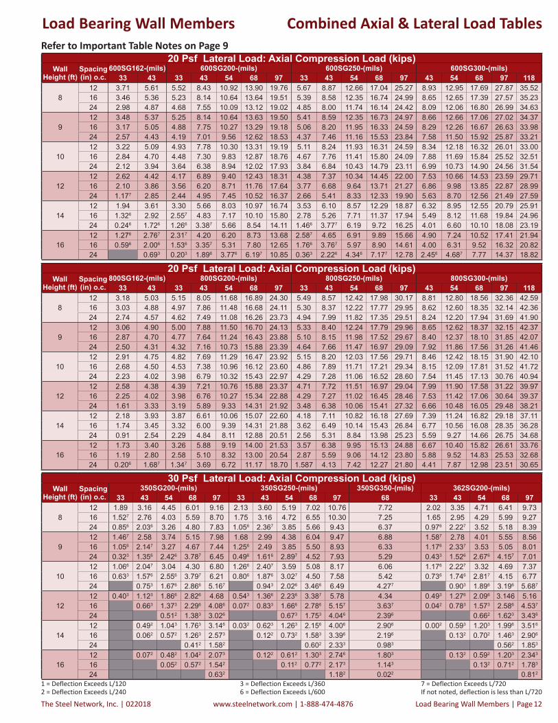
Important Notes:1. Allowable loads are based on weak axis and torsional bracing at 48" o.c. maximum for axial load calculation and continuous support
of each flange for flexural calculation.2. Sections are punched with a standard punch-out 1.5" wide located along the centerline of the web 24" o.c.3. Allowable loads are based on checks for punched section under axial load, flexural, and shear conditions.4. Weak axis and torsional bracing should have sufficient stiffness and strength to resist the axial load.5. The allowable axial strength for distortional buckling is based on an assumed k = 0.6. Lateral loads have not been modified for strength checks: full loads are applied.7. Listed wind pressures represent calculated design wind pressure (1.0W based on 2009 or 0.6W based on 2012 IBC).8. 15 psf and higher wind pressures have been multiplied by 0.7 for deflection determination, in accordance with footnote “f” of IBC
table 1604.3. The 5 psf pressure has not been reduced for deflection checks.9. 5 PSF is classified as live transverse loads, not wind loads, per 2009 IBC Section 1607.13 and 2012 IBC Section 1607.14. 10. Strength increase due to cold forming is incorporated in calculating allowable loads as per AISI Specification Sec. A7.2.11. Moment of inertia for deflection is optimized based on the maximum moment at service loads for the listed spans; therefore; span
values may be greater than spans based on an effective moment of inertia listed in section property tables.12. Contact The Steel Network if web crippling capacity values of SigmaStud® are required to check lateral end reactions.13. Loads in tables are in kips/stud (1 kip = 1,000 pounds).
1 = Deflection Exceeds L/1202 = Deflection Exceeds L/240
3 = Deflection Exceeds L/3606 = Deflection Exceeds L/600
7 = Deflection Exceeds L/720If not noted, deflection is less than L/720
5 Psf Lateral Load: Axial Compression Load (kips)Wall
Height (ft)Spacing (in) o.c.
350SG200-(mils) 350SG250-(mils) 350SG350-(mils) 362SG200-(mils)33 43 54 68 97 33 43 54 68 97 68 33 43 54 68 97
812 2.96 4.29 5.62 7.18 10.41 3.22 4.82 6.50 8.30 11.99 8.95 3.07 4.47 5.87 7.58 10.9816 2.88 4.20 5.53 7.10 10.32 3.14 4.73 6.41 8.21 11.90 8.87 2.99 4.39 5.78 7.49 10.8924 2.73 4.04 5.37 6.93 10.15 2.98 4.55 6.22 8.03 11.73 8.69 2.84 4.23 5.62 7.33 10.72
912 2.71 3.90 5.12 6.54 9.49 2.96 4.44 5.94 7.58 10.97 8.42 2.83 4.10 5.40 6.96 10.0816 2.61 3.80 5.01 6.44 9.38 2.86 4.33 5.83 7.47 10.86 8.31 2.73 4.00 5.29 6.85 9.9724 2.42 3.61 4.81 6.24 9.16 2.67 4.12 5.60 7.25 10.65 8.09 2.55 3.81 5.09 6.65 9.75
1012 2.44 3.50 4.58 5.87 8.52 2.68 4.04 5.34 6.83 9.90 7.90 2.57 3.71 4.90 6.29 9.1216 2.32 3.38 4.46 5.75 8.39 2.57 3.91 5.20 6.69 9.77 7.76 2.45 3.59 4.77 6.17 8.9924 2.11 3.16 4.23 5.51 8.13 2.35 3.66 4.93 6.44 9.52 7.49 2.24 3.36 4.53 5.93 8.73
1212 1.88 2.69 3.52 4.54 6.59 2.12 3.16 4.12 5.32 7.76 6.59 2.02 2.90 3.83 4.93 7.1616 1.75 2.56 3.37 4.39 6.43 1.97 3.00 3.96 5.16 7.60 6.40 1.88 2.75 3.68 4.78 7.0024 1.506 2.30 3.11 4.12 6.14 1.727 2.71 3.65 4.85 7.29 6.05 1.637 2.49 3.40 4.50 6.69
1412 1.40 2.04 2.67 3.48 5.07 1.62 2.40 3.14 4.09 6.02 5.30 1.51 2.21 2.92 3.80 5.5316 1.266 1.897 2.52 3.32 4.90 1.477 2.23 2.97 3.92 5.85 5.08 1.376 2.06 2.76 3.63 5.3524 1.016 1.636 2.256 3.047 4.59 1.206 1.936 2.667 3.60 5.52 4.69 1.116 1.796 2.477 3.34 5.03
1612 1.036 1.537 2.04 2.68 3.94 1.236 1.81 2.40 3.17 4.72 4.13 1.126 1.687 2.23 2.94 4.3116 0.896 1.396 1.896 2.537 3.77 1.086 1.646 2.237 2.99 4.53 3.91 0.986 1.536 2.087 2.77 4.1324 0.653 1.133 1.626 2.256 3.467 0.813 1.356 1.926 2.686 4.21 3.527 0.733 1.263 1.796 2.486 3.807
5 Psf Lateral Load: Axial Compression Load (kips)Wall
Height (ft)Spacing (in) o.c.
362SG250-(mils) 362SG350-(mils) 400SG200-(mils) 400SG250-(mils)33 43 54 68 97 68 33 43 54 68 97 33 43 54 68 97
812 3.33 5.00 6.79 8.75 12.63 9.36 3.36 4.95 6.52 8.60 12.60 3.64 5.45 7.35 9.92 14.4716 3.25 4.91 6.70 8.66 12.54 9.27 3.29 4.88 6.44 8.52 12.52 3.56 5.36 7.26 9.83 14.3924 3.10 4.74 6.52 8.48 12.38 9.10 3.14 4.72 6.29 8.37 12.35 3.42 5.21 7.10 9.65 14.22
912 3.08 4.64 6.26 8.05 11.63 8.79 3.15 4.63 6.11 8.07 11.78 3.42 5.15 7.01 9.30 13.5416 2.99 4.53 6.14 7.93 11.52 8.68 3.05 4.53 6.01 7.97 11.67 3.32 5.05 6.89 9.19 13.4424 2.80 4.32 5.91 7.71 11.31 8.47 2.88 4.34 5.81 7.77 11.45 3.15 4.85 6.68 8.97 13.23
1012 2.82 4.25 5.68 7.30 10.58 8.26 2.91 4.27 5.65 7.48 10.87 3.17 4.80 6.55 8.63 12.5416 2.70 4.12 5.54 7.17 10.45 8.13 2.80 4.15 5.53 7.36 10.74 3.06 4.68 6.42 8.49 12.4124 2.48 3.87 5.28 6.90 10.19 7.86 2.59 3.92 5.30 7.12 10.48 2.85 4.43 6.15 8.22 12.15
1212 2.25 3.40 4.48 5.77 8.41 7.05 2.39 3.50 4.67 6.17 8.94 2.65 4.04 5.43 7.17 10.4116 2.11 3.23 4.31 5.60 8.24 6.87 2.25 3.34 4.51 6.01 8.76 2.50 3.87 5.25 6.98 10.2324 1.85 2.93 3.99 5.28 7.93 6.51 1.99 3.06 4.21 5.69 8.42 2.23 3.55 4.91 6.63 9.89
1412 1.74 2.60 3.43 4.46 6.55 5.75 1.88 2.73 3.69 4.84 7.04 2.11 3.21 4.30 5.66 8.2816 1.597 2.42 3.24 4.27 6.37 5.53 1.72 2.57 3.51 4.66 6.84 1.94 3.02 4.10 5.45 8.0824 1.316 2.116 2.91 3.94 6.03 5.12 1.446 2.277 3.18 4.32 6.46 1.656 2.67 3.73 5.07 7.69
1612 1.337 1.98 2.63 3.46 5.14 4.50 1.427 2.12 2.88 3.78 5.52 1.65 2.49 3.37 4.43 6.5516 1.176 1.816 2.45 3.27 4.95 4.27 1.266 1.957 2.70 3.59 5.32 1.476 2.29 3.16 4.21 6.3324 0.903 1.506 2.126 2.947 4.61 3.86 0.983 1.656 2.376 3.257 4.94 1.176 1.956 2.787 3.83 5.94
Combined Axial & Lateral Load TablesLoad Bearing Wall Members

The Steel Network, Inc. | 022018 www.steelnetwork.com | 1-888-474-4876 Load Bearing Wall Members | Page 10
1 = Deflection Exceeds L/1202 = Deflection Exceeds L/240
3 = Deflection Exceeds L/3606 = Deflection Exceeds L/600
7 = Deflection Exceeds L/720If not noted, deflection is less than L/720
5 Psf Lateral Load: Axial Compression Load (kips)Wall
Height (ft)Spacing (in) o.c.
400SG350-(mils) 550SG162-(mils) 550SG200-(mils) 550SG250-(mils) 550SG300-(mils)68 97 118 33 43 33 43 54 68 97 33 43 54 68 97 43 54 68 97 118
812 10.36 16.99 21.91 4.38 5.71 6.23 8.58 10.88 13.63 19.09 6.34 9.60 12.68 16.87 24.65 9.59 13.16 17.19 26.82 33.9516 10.28 16.90 21.82 4.30 5.64 6.15 8.50 10.80 13.56 19.02 6.26 9.51 12.59 16.78 24.57 9.50 13.07 17.11 26.73 33.8624 10.12 16.73 21.65 4.16 5.51 5.98 8.34 10.65 13.42 18.89 6.10 9.33 12.42 16.62 24.41 9.34 12.91 16.95 26.57 33.70
912 9.88 16.11 20.57 4.30 5.64 6.14 8.49 10.79 13.55 19.02 6.26 9.50 12.58 16.77 24.56 9.50 12.77 16.71 26.08 32.8516 9.78 16.00 20.46 4.20 5.55 6.03 8.38 10.69 13.46 18.93 6.15 9.39 12.47 16.66 24.45 9.39 12.66 16.60 25.97 32.7424 9.57 15.78 20.24 4.01 5.38 5.81 8.17 10.49 13.27 18.74 5.94 9.15 12.24 16.43 24.23 9.17 12.45 16.39 25.75 32.53
1012 9.35 15.18 19.13 4.21 5.56 6.03 8.38 10.69 13.45 18.92 6.16 9.39 12.14 16.26 23.89 9.40 12.32 16.13 25.22 31.5716 9.22 15.04 18.99 4.09 5.44 5.89 8.24 10.55 13.33 18.80 6.02 9.23 11.99 16.12 23.74 9.25 12.18 16.00 25.09 31.4324 8.97 14.76 18.72 3.84 5.22 5.60 7.95 10.28 13.07 18.55 5.74 8.93 11.70 15.82 23.46 8.97 11.91 15.73 24.81 31.15
1212 8.27 13.14 16.08 3.96 5.33 5.72 8.05 10.37 13.15 18.62 5.88 8.58 11.00 14.89 21.53 8.64 11.23 14.79 23.27 28.5816 8.08 12.94 15.89 3.77 5.15 5.49 7.82 10.14 12.93 18.41 5.66 8.35 10.78 14.66 21.31 8.42 11.03 14.58 23.05 28.3724 7.72 12.55 15.52 3.41 4.81 5.05 7.37 9.70 12.51 17.99 5.24 7.91 10.35 14.21 20.88 8.01 10.63 14.18 22.62 27.94
1412 6.97 10.60 13.01 3.62 4.99 4.91 7.03 9.13 11.73 16.90 5.20 7.47 9.75 13.03 18.83 7.60 9.97 13.36 20.67 25.2116 6.74 10.36 12.77 3.35 4.73 4.61 6.72 8.82 11.42 16.58 4.91 7.17 9.45 12.72 18.53 7.32 9.69 13.07 20.36 24.9124 6.30 9.91 12.34 2.88 4.26 4.08 6.15 8.24 10.85 15.97 4.38 6.61 8.89 12.13 17.94 6.79 9.17 12.52 19.76 24.32
1612 5.70 8.44 10.40 3.15 4.50 3.98 5.75 7.54 9.79 14.21 4.29 6.30 8.43 10.98 16.02 6.51 8.62 11.70 17.72 21.6816 5.44 8.18 10.15 2.83 4.17 3.66 5.41 7.19 9.43 13.82 3.96 5.94 8.06 10.61 15.64 6.17 8.28 11.34 17.33 21.2924 4.97 7.71 9.68 2.296 3.60 3.11 4.81 6.57 8.79 13.13 3.39 5.32 7.40 9.94 14.95 5.56 7.65 10.67 16.61 20.57
5 Psf Lateral Load: Axial Compression Load (kips)Wall
Height (ft)Spacing (in) o.c.
600SG162-(mils) 600SG200-(mils) 600SG250-(mils) 600SG300-(mils)33 43 33 43 54 68 97 33 43 54 68 97 43 54 68 97 118
812 4.28 6.18 6.17 9.12 11.56 14.49 20.32 6.30 9.55 13.37 17.74 25.92 9.58 13.64 18.37 28.54 36.2016 4.21 6.12 6.10 9.04 11.49 14.42 20.25 6.23 9.47 13.29 17.66 25.85 9.50 13.56 18.29 28.47 36.1324 4.08 5.99 5.95 8.89 11.35 14.29 20.13 6.09 9.32 13.13 17.50 25.70 9.36 13.41 18.14 28.32 35.97
912 4.21 6.12 6.10 9.04 11.49 14.42 20.25 6.23 9.47 13.29 17.66 25.84 9.51 13.56 17.94 27.90 35.2616 4.13 6.03 6.00 8.94 11.39 14.33 20.17 6.14 9.37 13.18 17.55 25.74 9.41 13.46 17.84 27.80 35.1624 3.97 5.87 5.81 8.73 11.20 14.15 20.00 5.95 9.17 12.97 17.34 25.55 9.22 13.26 17.64 27.60 34.96
1012 4.14 6.04 6.01 8.94 11.39 14.33 20.17 6.15 9.38 13.14 17.53 25.74 9.42 13.33 17.43 27.13 34.1316 4.03 5.93 5.88 8.81 11.27 14.22 20.06 6.03 9.25 13.00 17.39 25.61 9.30 13.20 17.30 27.00 34.0124 3.82 5.72 5.64 8.54 11.02 13.98 19.84 5.79 8.99 12.72 17.12 25.35 9.05 12.94 17.05 26.75 33.75
1212 3.95 5.83 5.77 8.66 11.12 14.08 19.93 5.92 9.12 12.11 16.27 23.75 9.18 12.34 16.18 25.31 31.4316 3.78 5.66 5.57 8.44 10.92 13.89 19.74 5.74 8.91 11.90 16.05 23.55 8.99 12.14 15.99 25.11 31.2324 3.47 5.33 5.19 8.03 10.51 13.50 19.37 5.38 8.50 11.49 15.63 23.15 8.60 11.75 15.61 24.72 30.84
1412 3.68 5.52 5.41 8.01 10.40 13.34 19.19 5.60 8.42 10.85 14.73 21.24 8.53 11.15 14.78 23.21 28.3016 3.45 5.27 5.12 7.70 10.10 13.04 18.89 5.33 8.12 10.56 14.42 20.95 8.25 10.88 14.50 22.92 28.0124 3.03 4.81 4.61 7.12 9.52 12.47 18.30 4.83 7.56 10.02 13.84 20.40 7.72 10.36 13.98 22.36 27.46
1612 3.33 5.09 4.69 6.77 8.83 11.43 16.57 5.01 7.27 9.62 12.73 18.53 7.46 9.84 13.28 20.38 24.9116 3.04 4.76 4.35 6.41 8.47 11.06 16.19 4.67 6.91 9.25 12.35 18.15 7.12 9.50 12.92 20.00 24.5424 2.527 4.17 3.75 5.76 7.81 10.39 15.48 4.06 6.26 8.58 11.66 17.46 6.49 8.86 12.25 19.29 23.83
5 Psf Lateral Load: Axial Compression Load (kips)Wall
Height (ft)Spacing (in) o.c.
800SG162-(mils) 800SG200-(mils) 800SG250-(mils) 800SG300-(mils)33 43 33 43 54 68 97 33 43 54 68 97 43 54 68 97 118
812 3.51 5.38 5.56 8.48 12.13 17.37 24.73 5.90 9.00 12.88 18.46 30.67 9.25 13.25 19.03 32.87 43.1216 3.48 5.34 5.51 8.43 12.08 17.32 24.68 5.85 8.95 12.83 18.41 30.62 9.20 13.20 18.98 32.82 43.0624 3.40 5.27 5.42 8.34 11.98 17.21 24.59 5.76 8.85 12.73 18.30 30.51 9.10 13.10 18.88 32.71 42.94
912 3.48 5.35 5.52 8.44 12.08 17.32 24.69 5.86 8.96 12.83 18.41 30.62 9.20 13.21 18.99 32.82 43.0616 3.44 5.30 5.46 8.38 12.02 17.25 24.62 5.80 8.90 12.77 18.34 30.55 9.14 13.14 18.92 32.75 42.9824 3.34 5.20 5.34 8.25 11.89 17.11 24.50 5.68 8.77 12.64 18.21 30.40 9.02 13.01 18.78 32.60 42.83
1012 3.45 5.31 5.47 8.39 12.03 17.26 24.64 5.81 8.91 12.78 18.36 30.56 9.15 13.15 18.93 32.76 42.9916 3.39 5.25 5.40 8.31 11.95 17.17 24.56 5.74 8.83 12.70 18.27 30.46 9.08 13.07 18.84 32.66 42.9024 3.27 5.12 5.25 8.15 11.78 16.99 24.40 5.59 8.67 12.53 18.09 30.27 8.92 12.91 18.67 32.47 42.70
1212 3.36 5.21 5.36 8.26 11.89 17.11 24.49 5.70 8.78 12.64 18.20 30.39 9.03 13.02 18.78 32.59 41.3116 3.27 5.12 5.25 8.14 11.76 16.97 24.37 5.58 8.66 12.51 18.06 30.24 8.91 12.89 18.65 32.43 41.1624 3.09 4.93 5.03 7.91 11.51 16.69 24.12 5.36 8.42 12.26 17.79 29.93 8.68 12.64 18.38 32.13 40.86
1412 3.24 5.09 5.21 8.09 11.69 16.88 24.29 5.55 8.61 12.45 17.98 29.69 8.87 12.84 18.58 31.13 39.0316 3.12 4.95 5.05 7.92 11.51 16.67 24.09 5.39 8.44 12.26 17.78 29.46 8.70 12.65 18.38 30.91 38.8124 2.87 4.69 4.74 7.58 11.13 16.26 23.71 5.07 8.10 11.89 17.37 29.01 8.36 12.29 17.98 30.47 38.38
1612 3.10 4.92 5.01 7.86 11.42 16.55 23.97 5.35 8.39 12.19 17.67 27.54 8.65 12.59 18.28 29.25 36.3616 2.93 4.74 4.80 7.62 11.15 16.24 23.68 5.14 8.14 11.92 17.36 27.22 8.42 12.33 17.99 28.94 36.0624 2.61 4.39 4.39 7.15 10.63 15.64 23.12 4.72 7.68 11.40 16.77 26.61 7.96 11.82 17.42 28.33 35.46
Refer to Important Table Notes on Page 9
Combined Axial & Lateral Load TablesLoad Bearing Wall Members

022018 | The Steel Network, Inc.www.steelnetwork.com | 1-888-474-4876Page | Load Bearing Wall Members 11
1 = Deflection Exceeds L/1202 = Deflection Exceeds L/240
3 = Deflection Exceeds L/3606 = Deflection Exceeds L/600
7 = Deflection Exceeds L/720If not noted, deflection is less than L/720
Refer to Important Table Notes on Page 9
Combined Axial & Lateral Load Tables
20 Psf Lateral Load: Axial Compression Load (kips)Wall
Height (ft)Spacing (in) o.c.
350SG200-(mils) 350SG250-(mils) 350SG350-(mils) 362SG200-(mils)33 43 54 68 97 33 43 54 68 97 68 33 43 54 68 97
812 2.29 3.58 4.89 6.46 9.64 2.54 4.06 5.69 7.51 11.24 8.20 2.41 3.78 5.15 6.86 10.2116 2.02 3.30 4.59 6.16 9.32 2.27 3.75 5.35 7.18 10.92 7.87 2.15 3.49 4.86 6.56 9.8924 1.527 2.76 4.03 5.59 8.70 1.75 3.16 4.72 6.55 10.30 7.25 1.65 2.95 4.29 5.99 9.27
912 1.91 3.07 4.25 5.67 8.55 2.15 3.52 4.96 6.62 10.04 7.47 2.04 3.26 4.53 6.08 9.1316 1.61 2.74 3.90 5.32 8.16 1.83 3.16 4.57 6.23 9.66 7.07 1.73 2.93 4.18 5.72 8.7524 1.056 2.147 3.27 4.67 7.44 1.256 2.49 3.85 5.50 8.93 6.33 1.176 2.337 3.53 5.05 8.01
1012 1.547 2.56 3.60 4.88 7.43 1.76 2.98 4.22 5.72 8.82 6.74 1.67 2.75 3.89 5.27 8.0216 1.216 2.207 3.22 4.49 7.00 1.427 2.58 3.79 5.29 8.38 6.28 1.336 2.39 3.50 4.88 7.5824 0.633 1.576 2.556 3.797 6.21 0.806 1.876 3.027 4.50 7.58 5.42 0.736 1.746 2.817 4.15 6.77
1212 0.896 1.656 2.437 3.42 5.35 1.076 1.977 2.88 4.06 6.49 5.13 1.006 1.826 2.697 3.76 5.8716 0.563 1.296 2.046 3.017 4.89 0.703 1.556 2.436 3.607 6.01 4.59 0.653 1.446 2.286 3.337 5.3924 0.663 1.373 2.296 4.086 0.072 0.833 1.666 2.786 5.157 3.637 0.042 0.783 1.573 2.586 4.537
1412 0.423 1.003 1.586 2.346 3.807 0.553 1.206 1.896 2.806 4.69 3.71 0.493 1.126 1.776 2.606 4.2016 0.102 0.653 1.213 1.956 3.356 0.192 0.803 1.463 2.356 4.227 3.156 0.162 0.763 1.383 2.186 3.726
24 0.062 0.572 1.263 2.573 0.122 0.732 1.583 3.396 2.196 0.132 0.702 1.463 2.906
1612 0.102 0.542 0.993 1.583 2.696 0.182 0.673 1.193 1.916 3.406 2.576 0.152 0.633 1.123 1.776 3.006
16 0.222 0.642 1.213 2.273 0.292 0.803 1.493 2.956 2.046 0.292 0.762 1.383 2.556
24 0.052 0.572 1.542 0.112 0.772 2.173 1.143 0.132 0.712 1.783
20 Psf Lateral Load: Axial Compression Load (kips)Wall
Height (ft)Spacing (in) o.c.
362SG250-(mils) 362SG350-(mils) 400SG200-(mils) 400SG250-(mils)33 43 54 68 97 68 33 43 54 68 97 33 43 54 68 97
812 2.67 4.25 5.99 7.96 11.88 8.61 2.74 4.29 5.84 7.91 11.86 3.01 4.75 6.61 9.15 13.7416 2.39 3.94 5.65 7.63 11.57 8.29 2.48 4.01 5.55 7.61 11.54 2.74 4.45 6.30 8.82 13.4224 1.88 3.36 5.02 6.99 10.95 7.67 1.99 3.48 5.00 7.04 10.92 2.24 3.89 5.69 8.19 12.81
912 2.28 3.72 5.27 7.08 10.70 7.85 2.38 3.81 5.26 7.20 10.84 2.64 4.27 6.06 8.34 12.6216 1.96 3.36 4.88 6.68 10.32 7.46 2.08 3.48 4.91 6.84 10.44 2.33 3.92 5.67 7.93 12.2324 1.387 2.69 4.15 5.94 9.58 6.71 1.517 2.86 4.26 6.15 9.69 1.74 3.25 4.94 7.17 11.48
1012 1.89 3.19 4.55 6.17 9.48 7.12 2.02 3.31 4.65 6.43 9.74 2.26 3.76 5.42 7.47 11.4216 1.547 2.78 4.11 5.73 9.03 6.66 1.67 2.93 4.25 6.02 9.28 1.91 3.35 4.97 7.00 10.9524 0.916 2.066 3.327 4.91 8.21 5.79 1.056 2.257 3.52 5.24 8.42 1.266 2.60 4.14 6.14 10.09
1212 1.186 2.177 3.17 4.45 7.09 5.56 1.326 2.347 3.43 4.87 7.51 1.537 2.73 4.02 5.70 8.9616 0.816 1.736 2.717 3.97 6.59 5.00 0.946 1.926 2.987 4.38 6.97 1.136 2.267 3.50 5.16 8.4024 0.153 0.973 1.896 3.126 5.697 4.007 0.273 1.183 2.186 3.526 5.99 0.413 1.436 2.596 4.187 7.39
1412 0.633 1.356 2.106 3.107 5.16 4.08 0.753 1.526 2.376 3.467 5.51 0.916 1.826 2.807 4.10 6.7016 0.263 0.933 1.656 2.636 4.667 3.507 0.363 1.113 1.926 2.986 4.967 0.503 1.346 2.286 3.557 6.1224 0.212 0.883 1.813 3.796 2.496 0.392 1.143 2.143 4.006 0.523 1.393 2.596 5.106
1612 0.242 0.773 1.353 2.136 3.766 2.856 0.322 0.933 1.596 2.426 4.007 0.443 1.123 1.886 2.886 4.9516 0.382 0.933 1.693 3.286 2.306 0.532 1.153 1.963 3.486 0.042 0.673 1.393 2.366 4.396
24 0.212 0.922 2.463 1.353 0.422 1.172 2.573 0.542 1.463 3.426
20 Psf Lateral Load: Axial Compression Load (kips)Wall
Height (ft)Spacing (in) o.c.
400SG350-(mils) 550SG162-(mils) 550SG200-(mils) 550SG250-(mils) 550SG300-(mils)68 97 118 33 43 33 43 54 68 97 33 43 54 68 97 43 54 68 97 118
812 9.65 16.23 21.15 3.73 5.12 5.48 7.86 10.20 13.00 18.48 5.62 8.82 11.92 16.12 23.94 8.86 12.41 16.48 26.09 33.2116 9.34 15.90 20.81 3.45 4.87 5.16 7.54 9.90 12.72 18.22 5.31 8.49 11.59 15.79 23.62 8.54 12.09 16.16 25.77 32.8924 8.74 15.25 20.16 2.91 4.37 4.54 6.93 9.32 12.18 17.69 4.71 7.84 10.94 15.14 23.01 7.92 11.45 15.54 25.14 32.25
912 8.97 15.13 19.60 3.46 4.88 5.17 7.54 9.89 12.71 18.20 5.32 8.48 11.57 15.76 23.59 8.54 11.81 15.78 25.12 31.8916 8.59 14.71 19.18 3.11 4.55 4.76 7.13 9.50 12.34 17.84 4.93 8.05 11.14 15.33 23.17 8.13 11.40 15.37 24.71 31.4724 7.85 13.91 18.37 2.45 3.93 3.98 6.35 8.75 11.63 17.14 4.17 7.22 10.30 14.48 22.34 7.33 10.59 14.59 23.89 30.64
1012 8.24 13.97 17.93 3.16 4.59 4.79 7.15 9.51 12.34 17.84 4.97 8.07 10.87 14.97 22.63 8.16 11.11 14.96 24.00 30.3416 7.78 13.46 17.43 2.73 4.19 4.30 6.64 9.02 11.88 17.37 4.49 7.53 10.34 14.42 22.09 7.65 10.61 14.46 23.47 29.8124 6.91 12.50 16.47 1.95 3.43 3.37 5.70 8.09 10.98 16.47 3.58 6.51 9.32 13.38 21.05 6.67 9.63 13.49 22.45 28.78
1212 6.73 11.47 14.48 2.46 3.89 3.91 6.18 8.52 11.35 16.81 4.13 6.71 9.18 12.97 19.66 6.87 9.51 13.07 21.40 26.7316 6.14 10.81 13.84 1.91 3.34 3.25 5.48 7.81 10.65 16.08 3.48 6.00 8.47 12.21 18.90 6.18 8.82 12.37 20.63 25.9724 5.08 9.62 12.66 0.936 2.357 2.097 4.23 6.53 9.36 14.71 2.307 4.71 7.18 10.82 17.49 4.93 7.55 11.07 19.19 24.51
1412 5.17 8.72 11.17 1.737 3.08 2.79 4.75 6.81 9.38 14.39 3.06 5.19 7.44 10.59 16.39 5.42 7.77 11.06 18.16 22.7216 4.52 8.03 10.48 1.096 2.427 2.076 3.97 5.99 8.55 13.47 2.327 4.39 6.61 9.70 15.46 4.62 6.95 10.20 17.19 21.7524 3.396 6.817 9.26 1.286 0.846 2.636 4.587 7.07 11.83 1.046 2.996 5.157 8.13 13.81 3.227 5.50 8.65 15.46 19.98
1612 3.817 6.52 8.50 1.036 2.266 1.806 3.387 5.08 7.24 11.41 2.036 3.82 5.80 8.28 13.21 4.06 6.10 8.99 14.78 18.7016 3.166 5.84 7.82 0.363 1.556 1.096 2.616 4.277 6.38 10.44 1.286 3.006 4.937 7.36 12.22 3.237 5.23 8.04 13.73 17.6224 2.053 4.676 6.636 0.333 1.303 2.886 4.916 8.787 0.013 1.596 3.426 5.776 10.50 1.806 3.716 6.407 11.90 15.72
Load Bearing Wall Members
The Steel Network, Inc. | 022018 www.steelnetwork.com | 1-888-474-4876 Load Bearing Wall Members | Page 12
1 = Deflection Exceeds L/1202 = Deflection Exceeds L/240
3 = Deflection Exceeds L/3606 = Deflection Exceeds L/600
7 = Deflection Exceeds L/720If not noted, deflection is less than L/720
20 Psf Lateral Load: Axial Compression Load (kips)Wall
Height (ft)Spacing (in) o.c.
800SG162-(mils) 800SG200-(mils) 800SG250-(mils) 800SG300-(mils)33 43 33 43 54 68 97 33 43 54 68 97 43 54 68 97 118
812 3.18 5.03 5.15 8.05 11.68 16.89 24.30 5.49 8.57 12.42 17.98 30.17 8.81 12.80 18.56 32.36 42.5916 3.03 4.88 4.97 7.86 11.48 16.68 24.11 5.30 8.37 12.22 17.77 29.95 8.62 12.60 18.35 32.14 42.3624 2.74 4.57 4.62 7.49 11.08 16.26 23.73 4.94 7.99 11.82 17.35 29.51 8.24 12.20 17.94 31.69 41.90
912 3.06 4.90 5.00 7.88 11.50 16.70 24.13 5.33 8.40 12.24 17.79 29.96 8.65 12.62 18.37 32.15 42.3716 2.87 4.70 4.77 7.64 11.24 16.43 23.88 5.10 8.15 11.98 17.52 29.67 8.40 12.37 18.10 31.85 42.0724 2.50 4.31 4.32 7.16 10.73 15.88 23.39 4.64 7.66 11.47 16.97 29.09 7.92 11.86 17.56 31.26 41.46
1012 2.91 4.75 4.82 7.69 11.29 16.47 23.92 5.15 8.20 12.03 17.56 29.71 8.46 12.42 18.15 31.90 42.1016 2.68 4.50 4.53 7.38 10.96 16.12 23.60 4.86 7.89 11.71 17.21 29.34 8.15 12.09 17.81 31.52 41.7224 2.23 4.02 3.98 6.79 10.32 15.43 22.97 4.29 7.28 11.06 16.52 28.60 7.54 11.45 17.13 30.76 40.94
1212 2.58 4.38 4.39 7.21 10.76 15.88 23.37 4.71 7.72 11.51 16.97 29.04 7.99 11.90 17.58 31.22 39.9716 2.25 4.02 3.98 6.76 10.27 15.34 22.88 4.29 7.27 11.02 16.45 28.46 7.53 11.42 17.06 30.64 39.3724 1.61 3.33 3.19 5.89 9.33 14.31 21.92 3.48 6.38 10.06 15.41 27.32 6.66 10.48 16.05 29.48 38.21
1412 2.18 3.93 3.87 6.61 10.06 15.07 22.60 4.18 7.11 10.82 16.18 27.69 7.39 11.24 16.82 29.18 37.1116 1.74 3.45 3.32 6.00 9.39 14.31 21.88 3.62 6.49 10.14 15.43 26.84 6.77 10.56 16.08 28.35 36.2824 0.91 2.54 2.29 4.84 8.11 12.88 20.51 2.56 5.31 8.84 13.98 25.23 5.59 9.27 14.66 26.75 34.68
1612 1.73 3.40 3.26 5.88 9.19 14.00 21.53 3.57 6.38 9.95 15.13 24.88 6.67 10.40 15.82 26.61 33.7616 1.19 2.80 2.58 5.10 8.32 13.00 20.54 2.87 5.59 9.06 14.12 23.80 5.88 9.52 14.83 25.53 32.6824 0.206 1.687 1.347 3.69 6.72 11.17 18.70 1.587 4.13 7.42 12.27 21.80 4.41 7.87 12.98 23.51 30.65
Refer to Important Table Notes on Page 9
Combined Axial & Lateral Load Tables
20 Psf Lateral Load: Axial Compression Load (kips)Wall
Height (ft)Spacing (in) o.c.
600SG162-(mils) 600SG200-(mils) 600SG250-(mils) 600SG300-(mils)33 43 33 43 54 68 97 33 43 54 68 97 43 54 68 97 118
812 3.71 5.61 5.52 8.43 10.92 13.90 19.76 5.67 8.87 12.66 17.04 25.27 8.93 12.95 17.69 27.87 35.5216 3.46 5.36 5.23 8.14 10.64 13.64 19.51 5.39 8.58 12.35 16.74 24.99 8.65 12.65 17.39 27.57 35.2324 2.98 4.87 4.68 7.55 10.09 13.12 19.02 4.85 8.00 11.74 16.14 24.42 8.09 12.06 16.80 26.99 34.63
912 3.48 5.37 5.25 8.14 10.64 13.63 19.50 5.41 8.59 12.35 16.73 24.97 8.66 12.66 17.06 27.02 34.3716 3.17 5.05 4.88 7.75 10.27 13.29 19.18 5.06 8.20 11.95 16.33 24.59 8.29 12.26 16.67 26.63 33.9824 2.57 4.43 4.19 7.01 9.56 12.62 18.53 4.37 7.46 11.16 15.53 23.84 7.58 11.50 15.92 25.87 33.21
1012 3.22 5.09 4.93 7.78 10.30 13.31 19.19 5.11 8.24 11.93 16.31 24.59 8.34 12.18 16.32 26.01 33.0016 2.84 4.70 4.48 7.30 9.83 12.87 18.76 4.67 7.76 11.41 15.80 24.09 7.88 11.69 15.84 25.52 32.5124 2.12 3.94 3.64 6.38 8.94 12.02 17.93 3.84 6.84 10.43 14.79 23.11 6.99 10.73 14.90 24.56 31.54
1212 2.62 4.42 4.17 6.89 9.40 12.43 18.31 4.38 7.37 10.34 14.45 22.00 7.53 10.66 14.53 23.59 29.7116 2.10 3.86 3.56 6.20 8.71 11.76 17.64 3.77 6.68 9.64 13.71 21.27 6.86 9.98 13.85 22.87 28.9924 1.177 2.85 2.44 4.95 7.45 10.52 16.37 2.66 5.41 8.33 12.33 19.90 5.63 8.70 12.56 21.49 27.59
1412 1.94 3.61 3.30 5.66 8.03 10.97 16.74 3.53 6.10 8.57 12.29 18.87 6.32 8.95 12.55 20.79 25.9116 1.326 2.92 2.557 4.83 7.17 10.10 15.80 2.78 5.26 7.71 11.37 17.94 5.49 8.12 11.68 19.84 24.9624 0.246 1.726 1.266 3.387 5.66 8.54 14.11 1.466 3.777 6.19 9.72 16.25 4.01 6.60 10.10 18.08 23.19
1612 1.276 2.767 2.317 4.20 6.20 8.73 13.68 2.587 4.65 6.91 9.89 15.66 4.90 7.24 10.52 17.41 21.9416 0.596 2.006 1.536 3.357 5.31 7.80 12.65 1.766 3.767 5.97 8.90 14.61 4.00 6.31 9.52 16.32 20.8224 0.693 0.203 1.896 3.776 6.197 10.85 0.363 2.226 4.346 7.177 12.78 2.456 4.687 7.77 14.37 18.82
30 Psf Lateral Load: Axial Compression Load (kips)Wall
Height (ft)Spacing (in) o.c.
350SG200-(mils) 350SG250-(mils) 350SG350-(mils) 362SG200-(mils)33 43 54 68 97 33 43 54 68 97 68 33 43 54 68 97
812 1.89 3.16 4.45 6.01 9.16 2.13 3.60 5.19 7.02 10.76 7.72 2.02 3.35 4.71 6.41 9.7316 1.527 2.76 4.03 5.59 8.70 1.75 3.16 4.72 6.55 10.30 7.25 1.65 2.95 4.29 5.99 9.2724 0.856 2.036 3.26 4.80 7.83 1.056 2.367 3.85 5.66 9.43 6.37 0.976 2.227 3.52 5.18 8.39
912 1.467 2.58 3.74 5.15 7.98 1.68 2.99 4.38 6.04 9.47 6.88 1.587 2.78 4.01 5.55 8.5616 1.056 2.147 3.27 4.67 7.44 1.256 2.49 3.85 5.50 8.93 6.33 1.176 2.337 3.53 5.05 8.0124 0.323 1.356 2.426 3.787 6.45 0.496 1.616 2.897 4.52 7.93 5.29 0.433 1.526 2.676 4.157 7.01
1012 1.066 2.047 3.04 4.30 6.80 1.266 2.407 3.59 5.08 8.17 6.06 1.176 2.227 3.32 4.69 7.3716 0.633 1.576 2.556 3.797 6.21 0.806 1.876 3.027 4.50 7.58 5.42 0.736 1.746 2.817 4.15 6.7724 0.753 1.676 2.866 5.167 0.943 2.026 3.466 6.49 4.277 0.903 1.896 3.196 5.687
1212 0.403 1.123 1.866 2.826 4.68 0.543 1.366 2.236 3.387 5.78 4.34 0.493 1.276 2.096 3.146 5.1616 0.663 1.373 2.296 4.086 0.072 0.833 1.666 2.786 5.157 3.637 0.042 0.783 1.573 2.586 4.537
24 0.512 1.383 3.026 0.673 1.753 4.046 2.396 0.662 1.623 3.436
1412 0.492 1.043 1.763 3.146 0.032 0.623 1.263 2.156 4.006 2.906 0.002 0.593 1.203 1.996 3.516
16 0.062 0.572 1.263 2.573 0.122 0.732 1.583 3.396 2.196 0.132 0.702 1.463 2.906
24 0.412 1.582 0.602 2.333 0.983 0.562 1.853
1612 0.072 0.482 1.042 2.073 0.122 0.612 1.303 2.746 1.803 0.132 0.592 1.203 2.343
16 0.052 0.572 1.542 0.112 0.772 2.173 1.143 0.132 0.712 1.783
24 0.632 1.182 0.022 0.812
Load Bearing Wall Members

022018 | The Steel Network, Inc.www.steelnetwork.com | 1-888-474-4876Page | Load Bearing Wall Members 13
30 Psf Lateral Load: Axial Compression Load (kips)Wall
Height (ft)Spacing (in) o.c.
400SG350-(mils) 550SG162-(mils) 550SG200-(mils) 550SG250-(mils) 550SG300-(mils)68 97 118 33 43 33 43 54 68 97 33 43 54 68 97 43 54 68 97 118
812 9.19 15.73 20.65 3.31 4.74 5.01 7.39 9.75 12.58 18.08 5.16 8.32 11.43 15.63 23.47 8.38 11.93 16.01 25.61 32.7316 8.74 15.25 20.16 2.91 4.37 4.54 6.93 9.32 12.18 17.69 4.71 7.84 10.94 15.14 23.01 7.92 11.45 15.54 25.14 32.2524 7.87 14.31 19.21 2.14 3.66 3.66 6.05 8.48 11.38 16.91 3.84 6.89 10.01 14.20 22.10 7.01 10.52 14.64 24.20 31.31
912 8.40 14.51 18.97 2.94 4.39 4.56 6.93 9.31 12.16 17.67 4.73 7.84 10.93 15.11 22.96 7.93 11.19 15.17 24.50 31.2616 7.85 13.91 18.37 2.45 3.93 3.98 6.35 8.75 11.63 17.14 4.17 7.22 10.30 14.48 22.34 7.33 10.59 14.59 23.89 30.6424 6.81 12.76 17.20 1.52 3.04 2.90 5.26 7.69 10.61 16.12 3.11 6.04 9.11 13.26 21.14 6.20 9.44 13.44 22.69 29.42
1012 7.55 13.22 17.19 2.53 3.99 4.06 6.40 8.78 11.65 17.14 4.25 7.26 10.08 14.16 21.83 7.40 10.36 14.21 23.22 29.5516 6.91 12.50 16.47 1.95 3.43 3.37 5.70 8.09 10.98 16.47 3.58 6.51 9.32 13.38 21.05 6.67 9.63 13.49 22.45 28.7824 5.71 11.16 15.12 0.886 2.38 2.127 4.40 6.80 9.71 15.18 2.33 5.10 7.91 11.91 19.57 5.30 8.26 12.12 20.99 27.29
1212 5.86 10.50 13.53 1.657 3.08 2.95 5.15 7.47 10.31 15.72 3.17 5.66 8.13 11.85 18.54 5.86 8.49 12.03 20.26 25.5916 5.08 9.62 12.66 0.936 2.357 2.097 4.23 6.53 9.36 14.71 2.307 4.71 7.18 10.82 17.49 4.93 7.55 11.07 19.19 24.5124 3.686 8.05 11.09 1.056 0.596 2.616 4.857 7.65 12.88 0.786 3.036 5.46 8.97 15.56 3.267 5.84 9.30 17.21 22.50
1412 4.227 7.70 10.16 0.796 2.126 1.756 3.617 5.62 8.15 13.04 1.986 4.02 6.22 9.29 15.03 4.25 6.57 9.79 16.74 21.2916 3.396 6.817 9.26 1.286 0.846 2.636 4.587 7.07 11.83 1.046 2.996 5.157 8.13 13.81 3.227 5.50 8.65 15.46 19.9824 1.953 5.236 7.666 0.943 2.806 5.206 9.727 1.226 3.296 6.136 11.66 1.436 3.636 6.647 13.20 17.64
1612 2.866 5.537 7.50 0.053 1.223 0.773 2.266 3.896 5.997 10.00 0.946 2.626 4.527 6.93 11.76 2.856 4.827 7.60 13.25 17.1216 2.053 4.676 6.636 0.333 1.303 2.886 4.916 8.787 0.013 1.596 3.426 5.776 10.50 1.806 3.716 6.407 11.90 15.7224 0.662 3.183 5.116 1.153 3.083 6.686 1.553 3.786 8.336 1.813 4.326 9.587 13.29
30 Psf Lateral Load: Axial Compression Load (kips)Wall
Height (ft)Spacing (in) o.c.
362SG250-(mils) 362SG350-(mils) 400SG200-(mils) 400SG250-(mils)33 43 54 68 97 68 33 43 54 68 97 33 43 54 68 97
812 2.26 3.79 5.49 7.47 11.41 8.13 2.35 3.87 5.41 7.47 11.38 2.61 4.31 6.14 8.66 13.2716 1.88 3.36 5.02 6.99 10.95 7.67 1.99 3.48 5.00 7.04 10.92 2.24 3.89 5.69 8.19 12.8124 1.186 2.55 4.14 6.10 10.07 6.78 1.317 2.74 4.23 6.24 10.03 1.54 3.09 4.84 7.29 11.93
912 1.81 3.19 4.69 6.49 10.13 7.27 1.93 3.32 4.75 6.66 10.25 2.18 3.75 5.49 7.74 12.0416 1.387 2.69 4.15 5.94 9.58 6.71 1.517 2.86 4.26 6.15 9.69 1.74 3.25 4.94 7.17 11.4824 0.606 1.796 3.177 4.93 8.56 5.68 0.746 2.026 3.377 5.21 8.64 0.956 2.337 3.94 6.12 10.42
1012 1.386 2.59 3.90 5.51 8.82 6.43 1.517 2.75 4.06 5.81 9.06 1.74 3.15 4.75 6.78 10.7316 0.916 2.066 3.327 4.91 8.21 5.79 1.056 2.257 3.52 5.24 8.42 1.266 2.60 4.14 6.14 10.0924 0.093 1.106 2.286 3.836 7.09 4.63 0.233 1.356 2.556 4.207 7.24 0.406 1.606 3.036 4.97 8.89
1212 0.633 1.536 2.496 3.747 6.35 4.74 0.766 1.726 2.776 4.15 6.71 0.946 2.046 3.267 4.90 8.1416 0.153 0.973 1.896 3.126 5.697 4.007 0.273 1.183 2.186 3.526 5.99 0.413 1.436 2.596 4.187 7.3924 0.022 0.853 2.023 4.536 2.716 0.252 1.153 2.416 4.726 0.373 1.423 2.936 6.066
1412 0.092 0.743 1.453 2.416 4.436 3.236 0.192 0.923 1.716 2.766 4.707 0.313 1.133 2.056 3.296 5.8516 0.212 0.883 1.813 3.796 2.496 0.392 1.143 2.143 4.006 0.523 1.393 2.596 5.106
24 0.782 2.673 1.213 0.162 1.082 2.773 0.262 1.393 3.806
1612 0.202 0.742 1.483 3.066 2.046 0.352 0.963 1.753 3.236 0.462 1.163 2.126 4.136
16 0.212 0.922 2.463 1.353 0.422 1.172 2.573 0.542 1.463 3.426
24 1.422 0.162 0.192 1.432 0.342 2.213
30 Psf Lateral Load: Axial Compression Load (kips)Wall
Height (ft)Spacing (in) o.c.
600SG162-(mils) 600SG200-(mils) 600SG250-(mils) 600SG300-(mils)33 43 33 43 54 68 97 33 43 54 68 97 43 54 68 97 118
812 3.34 5.24 5.09 7.99 10.50 13.51 19.38 5.25 8.43 12.20 16.59 24.85 8.51 12.50 17.24 27.43 35.0816 2.98 4.87 4.68 7.55 10.09 13.12 19.02 4.85 8.00 11.74 16.14 24.42 8.09 12.06 16.80 26.99 34.6324 2.29 4.16 3.88 6.71 9.29 12.37 18.29 4.06 7.15 10.85 15.25 23.58 7.27 11.19 15.93 26.12 33.75
912 3.02 4.90 4.71 7.56 10.09 13.12 19.01 4.88 8.01 11.74 16.13 24.40 8.11 12.07 16.48 26.44 33.7916 2.57 4.43 4.19 7.01 9.56 12.62 18.53 4.37 7.46 11.16 15.53 23.84 7.58 11.50 15.92 25.87 33.2124 1.72 3.55 3.20 5.94 8.54 11.65 17.58 3.40 6.39 10.02 14.39 22.74 6.55 10.39 14.82 24.75 32.08
1012 2.66 4.50 4.27 7.07 9.61 12.66 18.55 4.46 7.53 11.16 15.54 23.84 7.65 11.44 15.60 25.27 32.2716 2.12 3.94 3.64 6.38 8.94 12.02 17.93 3.84 6.84 10.43 14.79 23.11 6.99 10.73 14.90 24.56 31.5424 1.137 2.88 2.47 5.10 7.68 10.81 16.73 2.67 5.55 9.03 13.36 21.71 5.74 9.38 13.56 23.18 30.14
1212 1.86 3.60 3.26 5.87 8.39 11.44 17.31 3.48 6.35 9.30 13.36 20.92 6.54 9.65 13.52 22.52 28.6316 1.177 2.85 2.44 4.95 7.45 10.52 16.37 2.66 5.41 8.33 12.33 19.90 5.63 8.70 12.56 21.49 27.5924 1.506 0.986 3.307 5.77 8.83 14.61 1.186 3.72 6.56 10.46 17.98 3.96 6.95 10.78 19.57 25.63
1412 1.046 2.607 2.217 4.44 6.77 9.69 15.36 2.437 4.86 7.31 10.93 17.50 5.10 7.72 11.27 19.38 24.5116 0.246 1.726 1.266 3.387 5.66 8.54 14.11 1.466 3.777 6.19 9.72 16.25 4.01 6.60 10.10 18.08 23.1924 0.183 1.546 3.736 6.537 11.90 1.876 4.236 7.587 14.02 2.106 4.617 8.01 15.74 20.80
1612 0.283 1.646 1.176 2.966 4.897 7.37 12.17 1.386 3.357 5.53 8.44 14.13 3.597 5.87 9.06 15.80 20.2916 0.693 0.203 1.896 3.776 6.197 10.85 0.363 2.226 4.346 7.177 12.78 2.456 4.687 7.77 14.37 18.8224 0.073 1.853 4.166 8.576 0.303 2.306 4.986 10.427 0.483 2.616 5.536 11.88 16.23
1 = Deflection Exceeds L/1202 = Deflection Exceeds L/240
3 = Deflection Exceeds L/3606 = Deflection Exceeds L/600
7 = Deflection Exceeds L/720If not noted, deflection is less than L/720
Refer to Important Table Notes on Page 9
Combined Axial & Lateral Load TablesLoad Bearing Wall Members

The Steel Network, Inc. | 022018 www.steelnetwork.com | 1-888-474-4876 Load Bearing Wall Members | Page 14
30 Psf Lateral Load: Axial Compression Load (kips)Wall
Height (ft)Spacing (in) o.c.
800SG162-(mils) 800SG200-(mils) 800SG250-(mils) 800SG300-(mils)33 43 33 43 54 68 97 33 43 54 68 97 43 54 68 97 118
812 2.96 4.80 4.88 7.77 11.38 16.58 24.02 5.21 8.28 12.12 17.67 29.84 8.53 12.50 18.25 32.03 42.2416 2.74 4.57 4.62 7.49 11.08 16.26 23.73 4.94 7.99 11.82 17.35 29.51 8.24 12.20 17.94 31.69 41.9024 2.31 4.12 4.09 6.93 10.49 15.63 23.17 4.40 7.42 11.23 16.72 28.84 7.68 11.61 17.31 31.01 41.21
912 2.78 4.61 4.66 7.52 11.11 16.29 23.76 4.98 8.03 11.86 17.38 29.53 8.28 12.24 17.97 31.71 41.9216 2.50 4.31 4.32 7.16 10.73 15.88 23.39 4.64 7.66 11.47 16.97 29.09 7.92 11.86 17.56 31.26 41.4624 1.95 3.73 3.65 6.45 9.97 15.07 22.65 3.96 6.94 10.71 16.16 28.23 7.20 11.10 16.76 30.39 40.56
1012 2.57 4.38 4.39 7.23 10.80 15.95 23.44 4.71 7.74 11.54 17.04 29.15 8.00 11.93 17.64 31.33 41.5216 2.23 4.02 3.98 6.79 10.32 15.43 22.97 4.29 7.28 11.06 16.52 28.60 7.54 11.45 17.13 30.76 40.9424 1.56 3.31 3.16 5.91 9.38 14.42 22.04 3.45 6.39 10.11 15.51 27.50 6.65 10.51 16.12 29.65 39.79
1212 2.08 3.85 3.78 6.54 10.03 15.08 22.64 4.09 7.04 10.78 16.18 28.17 7.31 11.18 16.81 30.34 39.0816 1.61 3.33 3.19 5.89 9.33 14.31 21.92 3.48 6.38 10.06 15.41 27.32 6.66 10.48 16.05 29.48 38.2124 0.70 2.34 2.06 4.66 7.98 12.83 20.52 2.33 5.12 8.69 13.92 25.66 5.39 9.11 14.57 27.78 36.51
1412 1.53 3.21 3.05 5.70 9.06 13.94 21.53 3.35 6.19 9.80 15.06 26.43 6.47 10.23 15.72 27.95 35.8816 0.91 2.54 2.29 4.84 8.11 12.88 20.51 2.56 5.31 8.84 13.98 25.23 5.59 9.27 14.66 26.75 34.6824 1.287 0.887 3.25 6.34 10.90 18.57 1.107 3.68 7.03 11.97 22.95 3.95 7.46 12.66 24.49 32.40
1612 0.937 2.51 2.26 4.73 7.90 12.52 20.06 2.53 5.21 8.64 13.64 23.28 5.50 9.09 14.35 25.01 32.1616 0.206 1.687 1.347 3.69 6.72 11.17 18.70 1.587 4.13 7.42 12.27 21.80 4.41 7.87 12.98 23.51 30.6524 0.196 1.816 4.607 8.75 16.21 2.186 5.23 9.78 19.07 2.437 5.66 10.48 20.74 27.84
1 = Deflection Exceeds L/1202 = Deflection Exceeds L/240
3 = Deflection Exceeds L/3606 = Deflection Exceeds L/600
7 = Deflection Exceeds L/720If not noted, deflection is less than L/720
Refer to Important Table Notes on Page 9
Combined Axial & Lateral Load Tables
40 Psf Lateral Load: Axial Compression Load (kips)Wall
Height (ft)Spacing (in) o.c.
350SG200-(mils) 350SG250-(mils) 350SG350-(mils) 362SG200-(mils)33 43 54 68 97 33 43 54 68 97 68 33 43 54 68 97
812 1.527 2.76 4.03 5.59 8.70 1.75 3.16 4.72 6.55 10.30 7.25 1.65 2.95 4.29 5.99 9.2716 1.076 2.277 3.51 5.05 8.11 1.287 2.62 4.13 5.95 9.71 6.66 1.186 2.46 3.77 5.44 8.6824 0.243 1.376 2.556 4.067 7.01 0.416 1.636 3.047 4.85 8.60 5.54 0.356 1.556 2.806 4.44 7.57
912 1.056 2.147 3.27 4.67 7.44 1.256 2.49 3.85 5.50 8.93 6.33 1.176 2.337 3.53 5.05 8.0116 0.566 1.606 2.696 4.077 6.77 0.736 1.896 3.197 4.83 8.25 5.63 0.666 1.786 2.947 4.44 7.3324 0.643 1.666 2.996 5.557 0.826 2.026 3.626 7.00 4.35 0.803 1.896 3.336 6.087
1012 0.633 1.576 2.556 3.797 6.21 0.806 1.876 3.027 4.50 7.58 5.42 0.736 1.746 2.817 4.15 6.7716 0.123 1.013 1.946 3.156 5.507 0.253 1.236 2.346 3.797 6.84 4.64 0.213 1.176 2.186 3.506 6.0324 0.042 0.893 2.043 4.226 0.133 1.133 2.536 5.516 3.236 0.163 1.093 2.336 4.716
1212 0.663 1.373 2.296 4.086 0.072 0.833 1.666 2.786 5.157 3.637 0.042 0.783 1.573 2.586 4.537
16 0.112 0.783 1.673 3.366 0.202 0.983 2.073 4.396 2.786 0.212 0.953 1.923 3.786
24 0.592 2.113 0.842 3.073 1.303 0.782 2.463
1412 0.062 0.572 1.263 2.573 0.122 0.732 1.583 3.396 2.196 0.132 0.702 1.463 2.906
16 0.022 0.682 1.893 0.102 0.912 2.663 1.363 0.122 0.842 2.183
24 0.732 1.422 0.962
1612 0.052 0.572 1.542 0.112 0.772 2.173 1.143 0.132 0.712 1.783
16 0.032 0.912 0.152 1.492 0.372 0.142 1.122
24 0.342
40 Psf Lateral Load: Axial Compression Load (kips)Wall
Height (ft)Spacing (in) o.c.
362SG250-(mils) 362SG350-(mils) 400SG200-(mils) 400SG250-(mils)33 43 54 68 97 68 33 43 54 68 97 33 43 54 68 97
812 1.88 3.36 5.02 6.99 10.95 7.67 1.99 3.48 5.00 7.04 10.92 2.24 3.89 5.69 8.19 12.8116 1.407 2.81 4.42 6.39 10.36 7.07 1.537 2.98 4.48 6.50 10.32 1.77 3.35 5.12 7.58 12.2224 0.536 1.816 3.337 5.27 9.24 5.95 0.686 2.057 3.50 5.48 9.19 0.896 2.367 4.04 6.44 11.08
912 1.387 2.69 4.15 5.94 9.58 6.71 1.517 2.86 4.26 6.15 9.69 1.74 3.25 4.94 7.17 11.4816 0.856 2.086 3.48 5.25 8.89 6.01 0.996 2.297 3.66 5.51 8.98 1.206 2.63 4.26 6.46 10.7624 0.996 2.286 4.017 7.62 4.72 0.063 1.266 2.566 4.347 7.67 0.226 1.506 3.037 5.15 9.43
1012 0.916 2.066 3.327 4.91 8.21 5.79 1.056 2.257 3.52 5.24 8.42 1.266 2.60 4.14 6.14 10.0916 0.353 1.416 2.616 4.187 7.45 5.00 0.496 1.636 2.866 4.537 7.62 0.676 1.926 3.397 5.34 9.2824 0.273 1.363 2.876 6.087 3.576 0.543 1.686 3.266 6.187 0.716 2.046 3.926 7.80
1212 0.153 0.973 1.896 3.126 5.697 4.007 0.273 1.183 2.186 3.526 5.99 0.413 1.436 2.596 4.187 7.3916 0.323 1.183 2.376 4.906 3.126 0.543 1.483 2.766 5.136 0.703 1.796 3.336 6.497
24 1.073 3.503 1.583 0.262 1.443 3.616 0.413 1.833 4.896
1412 0.212 0.883 1.813 3.796 2.496 0.392 1.143 2.143 4.006 0.523 1.393 2.596 5.106
16 0.212 1.103 3.023 1.613 0.462 1.413 3.163 0.613 1.773 4.216
24 1.712 0.122 0.172 1.722 0.352 2.683
1612 0.212 0.922 2.463 1.353 0.422 1.172 2.573 0.542 1.463 3.426
16 0.272 1.752 0.532 0.502 1.793 0.692 2.593
24 0.532 0.452 1.162
Load Bearing Wall Members

022018 | The Steel Network, Inc.www.steelnetwork.com | 1-888-474-4876Page | Load Bearing Wall Members 15
40 Psf Lateral Load: Axial Compression Load (kips)Wall
Height (ft)Spacing (in) o.c.
400SG350-(mils) 550SG162-(mils) 550SG200-(mils) 550SG250-(mils) 550SG300-(mils)68 97 118 33 43 33 43 54 68 97 33 43 54 68 97 43 54 68 97 118
812 8.74 15.25 20.16 2.91 4.37 4.54 6.93 9.32 12.18 17.69 4.71 7.84 10.94 15.14 23.01 7.92 11.45 15.54 25.14 32.2516 8.16 14.62 19.52 2.39 3.89 3.95 6.34 8.76 11.64 17.16 4.13 7.20 10.31 14.51 22.40 7.31 10.83 14.94 24.51 31.6224 7.05 13.40 18.29 1.42 2.97 2.82 5.21 7.67 10.61 16.14 3.02 5.99 9.10 13.28 21.20 6.14 9.61 13.75 23.29 30.37
912 7.85 13.91 18.37 2.45 3.93 3.98 6.35 8.75 11.63 17.14 4.17 7.22 10.30 14.48 22.34 7.33 10.59 14.59 23.89 30.6416 7.15 13.13 17.58 1.82 3.33 3.25 5.61 8.03 10.94 16.46 3.45 6.42 9.50 13.66 21.54 6.57 9.81 13.82 23.09 29.8224 5.83 11.67 16.10 0.666 2.21 1.90 4.23 6.68 9.63 15.13 2.11 4.93 7.98 12.10 19.98 5.12 8.33 12.35 21.54 28.25
1012 6.91 12.50 16.47 1.95 3.43 3.37 5.70 8.09 10.98 16.47 3.58 6.51 9.32 13.38 21.05 6.67 9.63 13.49 22.45 28.7816 6.10 11.60 15.56 1.227 2.72 2.52 4.81 7.21 10.12 15.60 2.73 5.56 8.37 12.39 20.05 5.74 8.71 12.57 21.47 27.7824 4.627 9.93 13.87 1.436 0.996 3.217 5.60 8.53 13.96 1.197 3.82 6.61 10.54 18.16 4.04 6.98 10.82 19.59 25.85
1212 5.08 9.62 12.66 0.936 2.357 2.097 4.23 6.53 9.36 14.71 2.307 4.71 7.18 10.82 17.49 4.93 7.55 11.07 19.19 24.5116 4.127 8.55 11.60 0.066 1.466 1.066 3.136 5.38 8.19 13.47 1.266 3.567 6.01 9.56 16.18 3.79 6.39 9.87 17.85 23.1524 2.446 6.656 9.687 1.206 3.386 6.127 11.22 1.556 3.936 7.317 13.82 1.776 4.317 7.70 15.40 20.65
1412 3.396 6.817 9.26 1.286 0.846 2.636 4.587 7.07 11.83 1.046 2.996 5.157 8.13 13.81 3.227 5.50 8.65 15.46 19.9816 2.416 5.736 8.177 0.293 1.476 3.366 5.796 10.39 1.786 3.886 6.767 12.34 2.006 4.226 7.28 13.91 18.3924 0.713 3.873 6.276 1.273 3.586 7.896 1.693 4.396 9.787 1.996 4.886 11.207 15.57
1612 2.053 4.676 6.636 0.333 1.303 2.886 4.916 8.787 0.013 1.596 3.426 5.776 10.50 1.806 3.716 6.407 11.90 15.7216 1.103 3.656 5.596 0.183 1.693 3.656 7.346 0.393 2.143 4.406 9.017 0.563 2.416 4.976 10.317 14.0624 1.913 3.803 1.523 4.893 2.093 6.466 0.183 2.543 7.586 11.196
40 Psf Lateral Load: Axial Compression Load (kips)Wall
Height (ft)Spacing (in) o.c.
600SG162-(mils) 600SG200-(mils) 600SG250-(mils) 600SG300-(mils)33 43 33 43 54 68 97 33 43 54 68 97 43 54 68 97 118
812 2.98 4.87 4.68 7.55 10.09 13.12 19.02 4.85 8.00 11.74 16.14 24.42 8.09 12.06 16.80 26.99 34.6316 2.52 4.40 4.14 6.99 9.55 12.62 18.53 4.32 7.43 11.15 15.54 23.86 7.54 11.48 16.22 26.40 34.0424 1.63 3.48 3.11 5.89 8.50 11.63 17.57 3.31 6.33 9.98 14.38 22.76 6.48 10.34 15.07 25.26 32.88
912 2.57 4.43 4.19 7.01 9.56 12.62 18.53 4.37 7.46 11.16 15.53 23.84 7.58 11.50 15.92 25.87 33.2116 2.00 3.84 3.52 6.29 8.87 11.97 17.89 3.72 6.74 10.39 14.77 23.10 6.89 10.75 15.18 25.12 32.4624 0.937 2.71 2.26 4.93 7.55 10.70 16.65 2.47 5.37 8.92 13.28 21.66 5.55 9.31 13.75 23.66 30.97
1012 2.12 3.94 3.64 6.38 8.94 12.02 17.93 3.84 6.84 10.43 14.79 23.11 6.99 10.73 14.90 24.56 31.5416 1.45 3.23 2.84 5.51 8.09 11.20 17.13 3.05 5.97 9.49 13.83 22.17 6.15 9.82 14.00 23.63 30.6024 0.216 1.907 1.397 3.91 6.50 9.66 15.58 1.60 4.34 7.72 12.01 20.36 4.55 8.09 12.28 21.84 28.77
1212 1.177 2.85 2.44 4.95 7.45 10.52 16.37 2.66 5.41 8.33 12.33 19.90 5.63 8.70 12.56 21.49 27.5916 0.336 1.936 1.456 3.83 6.31 9.37 15.18 1.657 4.26 7.13 11.06 18.60 4.49 7.51 11.36 20.20 26.2724 0.306 1.846 4.266 7.29 12.98 2.216 4.977 8.76 16.22 2.457 5.36 9.14 17.78 23.80
1412 0.246 1.726 1.266 3.387 5.66 8.54 14.11 1.466 3.777 6.19 9.72 16.25 4.01 6.60 10.10 18.08 23.1916 0.676 0.143 2.126 4.346 7.167 12.60 0.316 2.476 4.857 8.26 14.73 2.706 5.247 8.68 16.48 21.5724 2.066 4.786 9.957 0.233 2.516 5.716 12.03 0.436 2.866 6.166 13.64 18.66
1612 0.693 0.203 1.896 3.776 6.197 10.85 0.363 2.226 4.346 7.177 12.78 2.456 4.687 7.77 14.37 18.8216 0.643 2.456 4.796 9.297 0.913 2.956 5.676 11.17 1.106 3.266 6.247 12.66 17.0524 0.213 2.423 6.616 0.563 3.113 8.386 0.823 3.606 9.706 13.967
40 Psf Lateral Load: Axial Compression Load (kips)Wall
Height (ft)Spacing (in) o.c.
800SG162-(mils) 800SG200-(mils) 800SG250-(mils) 800SG300-(mils)33 43 33 43 54 68 97 33 43 54 68 97 43 54 68 97 118
812 2.74 4.57 4.62 7.49 11.08 16.26 23.73 4.94 7.99 11.82 17.35 29.51 8.24 12.20 17.94 31.69 41.9016 2.45 4.27 4.27 7.11 10.69 15.84 23.36 4.58 7.61 11.42 16.93 29.06 7.87 11.81 17.52 31.23 41.4424 1.88 3.67 3.57 6.37 9.91 15.02 22.61 3.87 6.86 10.64 16.10 28.19 7.12 11.03 16.70 30.34 40.52
912 2.50 4.31 4.32 7.16 10.73 15.88 23.39 4.64 7.66 11.47 16.97 29.09 7.92 11.86 17.56 31.26 41.4616 2.13 3.93 3.87 6.68 10.22 15.34 22.89 4.18 7.18 10.96 16.43 28.51 7.44 11.35 17.03 30.68 40.8624 1.42 3.17 3.00 5.75 9.23 14.28 21.92 3.29 6.23 9.95 15.36 27.38 6.49 10.35 15.97 29.52 39.67
1012 2.23 4.02 3.98 6.79 10.32 15.43 22.97 4.29 7.28 11.06 16.52 28.60 7.54 11.45 17.13 30.76 40.9416 1.78 3.54 3.43 6.20 9.69 14.75 22.35 3.73 6.69 10.42 15.84 27.87 6.95 10.82 16.46 30.02 40.1724 0.92 2.62 2.37 5.05 8.46 13.43 21.13 2.65 5.52 9.18 14.51 26.42 5.78 9.59 15.13 28.55 38.65
1212 1.61 3.33 3.19 5.89 9.33 14.31 21.92 3.48 6.38 10.06 15.41 27.32 6.66 10.48 16.05 29.48 38.2116 0.99 2.66 2.43 5.06 8.42 13.31 20.99 2.71 5.53 9.14 14.41 26.20 5.81 9.56 15.05 28.34 37.0724 1.40 1.00 3.48 6.69 11.41 19.17 1.23 3.92 7.38 12.48 24.06 4.18 7.80 13.14 26.15 34.87
1412 0.91 2.54 2.29 4.84 8.11 12.88 20.51 2.56 5.31 8.84 13.98 25.23 5.59 9.27 14.66 26.75 34.6816 0.146 1.68 1.337 3.77 6.91 11.54 19.20 1.57 4.21 7.61 12.62 23.69 4.48 8.05 13.31 25.23 33.1524 0.116 1.806 4.72 9.07 16.74 2.177 5.36 10.10 20.82 2.42 5.78 10.78 22.35 30.24
1612 0.206 1.687 1.347 3.69 6.72 11.17 18.70 1.587 4.13 7.42 12.27 21.80 4.41 7.87 12.98 23.51 30.6516 0.676 0.236 2.416 5.28 9.52 17.01 0.426 2.807 5.93 10.57 19.95 3.06 6.37 11.28 21.63 28.7524 0.146 2.716 6.597 13.95 0.446 3.276 7.557 16.61 0.646 3.667 8.22 18.22 25.26
1 = Deflection Exceeds L/1202 = Deflection Exceeds L/240
3 = Deflection Exceeds L/3606 = Deflection Exceeds L/600
7 = Deflection Exceeds L/720If not noted, deflection is less than L/720
Refer to Important Table Notes on Page 9
Combined Axial & Lateral Load TablesLoad Bearing Wall Members

The Steel Network, Inc. | 022018 www.steelnetwork.com | 1-888-474-4876 Load Bearing Wall Members | Page 16
SigmaStud® STC Ratings and UL AssembliesFire RatingsSigmaStud® projects have revealed that a proprietary shaped load-bearing member does not affect the fire rating of a wall versus using standard (S) section studs. The general requirements of steel studs in a fire-rated load bearing wall includes that the studs shall be designed in accordance with the current edition of the AISI Specification for the Design of Cold-Formed Steel Structural Members. Studs shall be corrosion-protected, have a minimum stud size of 3.5 inches, minimum thickness of 33 mil (20 ga), and maximum spacing between studs shall not exceed 16 or 24 inches.UL's Fire Resistance Ratings vary from 45 minutes to 4 hours. The full report for each Fire Resistance Rating can be found on UL's website (www.ul.com). To obtain the report, click on Online Certifications Directory under Tools at the bottom of the UL homepage. Search by UL File Number. Click on the file link to view report. For technical assistance, please contact UL directly at 1-877-ULHELPS.A complete listing of all UL Fire Resistance Ratings for use with cold-formed steel studs can be obtained through UL; we have simply attempted to outline the more commonly-used ratings below.
Sound Transmission RatingsThe Gypsum Association maintains details to obtain fire resistance and Sound Transmission Class (STC) Ratings. These details are designated by a Wall and Partition (WP) System. Each detail is outlined in the Gypsum Association Fire Resistance Design Manual. The details mentioned below were obtained from the 20th Edition - June 2012 publication. For additional information on Gypsum Association or to acquire a copy of the Manual, visit www.gypsum.org. A complete listing of all WP details is not shown; TSN has attempted to list only the generic details unless no generic details were available for a specific application.
Load Bearing WP Details WP 1021 - 1 hr (50-54 STC)WP 1024 - 1 hr (50-54 STC)WP 1516 - 2 hr (55-59 STC)WP 1522 - 2 hr (55-59 STC)WP 1635 - 2 hr (45-49 STC)WP 1714 - 2 hr (40-44 STC)WP 1716 - 2 hr (40-44 STC)WP 8006 - 1 hr (NO STC)* WP 8203 - 2 hr (NO STC)* * Proprietary System
Load Bearing Fire Rated DetailsU404 - LOADBEARING (1 or 2 hr) - Interior WallU407 - LOADBEARING (1 hr) - Interior WallU418 - LOADBEARING (45 min - 2 hr) - Exterior WallU423 - LOADBEARING (45min - 2 hr) - Interior WallU424 - LOADBEARING (45 min - 2 hr) - Exterior WallU425 - LOADBEARING (45 min - 2 hr) - Exterior Wall with detail for InteriorU426 - LOADBEARING (3 hr) - Interior WallU432 - LOADBEARING (1 hr) - Interior WallU434 - LOADBEARING (1 hr) - Interior WallU440 - LOADBEARING (1 hr) - Interior WallU460 - LOADBEARING (1 hr) - Interior WallU462 - LOADBEARING (3 hr) - Interior WallU473 - LOADBEARING (1 hr) - Interior WallU477 - LOADBEARING (2 hr) - Interior WallU485 - LOADBEARING (1 hr) - Interior WallU487 - LOADBEARING (1 hr) - Interior WallU490 - LOADBEARING (3 or 4 hr) - Interior WallU530 - LOADBEARING (4 hr) - Interior WallV415 - LOADBEARING (2 hr) - Interior WallV420 - LOADBEARING (2 hr) - Interior WallV432 - LOADBEARING (1 hr) - Exterior WallV434 - LOADBEARING (1 hr) - Interior WallV446 - LOADBEARING (1 or 2 hr) - Interior
Load Bearing Wall Members

022018 | The Steel Network, Inc.www.steelnetwork.com | 1-888-474-4876Page | Load Bearing Wall Members 17
Material Properties:ASTM A1003/A1003M or ASTM A653/A653M, G-60 (Z180) minimum hot-dipped galvanized coating; or equivalent. Grade 50 (340), 50ksi (340 MPa) minimum yield strength, 65ksi (450 MPa) minimum tensile strength or 33ksi (230MPa) minimum yield strength, 45ksi (310 MPa) minimum tensile strength.
SigmaStud® Web Reinforcement
Reinforcing Non-Standard Holes in SigmaStud® Any larger holes cut into SigmaStud® require a review by the engineer, as load capacity is based on the existence of standard punchout sizes. With the realiza on that addi onal holes do manage to appear in studs, TSN provides the SigmaStud (SG) Web RFT to provide reinforcement of a hole or holes added to the stud web during construc on, when holes larger than the standard knockout are introduced into the web of the member. Use of the SG Web RFT ensures that the load capacity of the stud is not compromised when these types of oversized holes are present.
• No loss of stud strength when using the SigmaStud Web RFT with up to a 3" hole.• Each SigmaStud Web RFT contains 12 pre-drilled guide holes in the center sec on and 12 in the outside
fl anges, 6 per side, to ensure proper placement of the (24) #12 self-drilling self-tapping screws required.• All modifi ca ons to SigmaStud must be reviewed by a structural engineer).• Contact TSN’s Project Management Team at (888) 474-4876 for more recommenda ons.• Non standard holes may not exceed half of stud depth.may not exceed half of stud depth.
SigmaStud® PunchoutsEach SigmaStud contains punchouts which are 1.5” wide and 4” tall, spaced every 24” o.c. ver cally. The fi rst punchout begins 12" o.c. from the end of the stud.Custom punchout spacing is available upon request. Some restric ons apply.
3” Maximum Hole Diameter
NomenclatureSigmaStud® Web RFT is available in 54 or 97 mil thicknesses, and is designed for use with 550 & greater sized SigmaStud. Designate: SG Web RFT-54 or SG Web RFT-97 * Use SG Web RFT-54 for SigmaStud 54mil and lower. Use SG Web RFT-97 for SigmaStud 97mil and higher.
Wall In-Line Framing Building loads must transfer from the vertical element above (e.g. SigmaStud® wall) to the horizontal element (e.g. Floor System), and to the vertical bearing element below (e.g. SigmaStud wall). To achieve this load transfer, the wall framing must align vertically.
Trusses bearing on the studs, which are aligned vertically to the foundation (red lines). When truss spacing differs from stud spacing, a distribution lintel is required to transfer the load from
the truss to the studs below (blue line).
Example of framing aligned vertically. The red lines trace the axial load vertically from the roof to the foundation.
SigmaStud®: Important Design Considerations
Load Bearing Wall Members

The Steel Network, Inc. | 022018 www.steelnetwork.com | 1-888-474-4876 Load Bearing Wall Members | Page 18
SigmaTrak® Introduction
Product Descrip onSigmaTrak® is the ideal runner track for load bearing and curtain wall metal stud wall assemblies. Manufactured from mill-cer fi ed steel, SigmaTrak’s unique shape is designed to allow a stud to seat fully within the track, providing full bearing at the top and bo om structural tracks. Load bearing studs must be fully seated within the top and bo om tracks according to design standards. SigmaTrak eliminates fi eld issues typically seen with (T) sec on tracks where the studs bear directly on the corner radius of the track, crea ng gaps between the stud and track.
Standard track (T) sec ons (above le ) can contain an inside corner radius that prevents “full” bearing within the track. SigmaTrak (above right) allows full bearing of the stud within the track
Load bearing walls are designed to fully seat within the top and bo om tracks. Design standards recommend a maximum gap of ⅛” in order to obtain an eff ec ve bearing condi on.
Material Properties:ASTM A1003/A1003M or ASTM A653/A653M, G-60 (Z180) minimum hot-dipped galvanized coating; or equivalent. Grade 50 (340), 50ksi (340 MPa) minimum yield strength, 65ksi (450 MPa) minimum tensile strength or 33ksi (230MPa) minimum yield strength, 45ksi (310 MPa) minimum tensile strength.
Benefits That Add Value:• Track web is oversized to allow the stud to seat fully in the track• Eliminates the gap between the stud and the track as a result of bearing on corner radii• Faster assembly than with standard track (no forcing/squeezing stud into bearing on track radii)• Manufactured from traceable mill-certified steel• Manufacturing tolerances based on ASTM C955-11c
Max. ⅛”
Track Recommendations• The top and bottom track should match the stud thickness• Minimum track thickness = 54mils• When welding is required to the top track, it is recommended to use a 14ga (68mils) thickness. Welding
may be used as a means of attaching light gauge components, and should be performed by an AWS certified welder.
Load Bearing Wall Members

022018 | The Steel Network, Inc.www.steelnetwork.com | 1-888-474-4876Page | Load Bearing Wall Members 19
SigmaTrak® Section Properties
Section(All 50 ksi)
Design Thickness
Gross Properties Eff ective Properties Torsional
Area Weight Ix Sx Rx Iy Ry Ixe Sxe Ma Vag Iye1 Mya
1 Iye2 Mya
2 Jx1000 Cw Xo m Roß
(in) (in2) (lb/ft) (in4) (in3) (in) (in4) (in) (in4) (in3) (in-k) (lb) (in4) (in-k) (in4) (in-k) (in4) (in6) (in) (in) (in)
350SGT150-33 0.0346 0.229 0.778 0.498 0.264 1.476 0.050 0.467 0.409 0.172 5.158 1,053 0.050 0.116 0.047 1.218 0.091 0.120 -0.867 0.533 1.774 0.761
350SGT150-43 0.0451 0.298 1.013 0.651 0.343 1.479 0.064 0.465 0.566 0.243 7.263 2,141 0.064 0.275 0.064 1.634 0.202 0.156 -0.862 0.531 1.774 0.764
350SGT150-54 0.0566 0.373 1.270 0.819 0.429 1.482 0.080 0.463 0.747 0.327 9.804 3,372 0.080 0.610 0.080 2.084 0.399 0.194 -0.857 0.528 1.773 0.766
350SGT150-68 0.0713 0.470 1.599 1.036 0.538 1.485 0.099 0.460 0.988 0.446 13.355 4,679 0.099 1.381 0.099 2.613 0.796 0.243 -0.851 0.525 1.772 0.770
350SGT150-97 0.1017 0.669 2.276 1.489 0.761 1.492 0.138 0.454 1.489 0.717 21.457 6,674 0.138 3.657 0.138 3.657 2.306 0.342 -0.838 0.518 1.771 0.776
350SGT150-118 0.1242 0.814 2.771 1.825 0.922 1.497 0.165 0.450 1.825 0.922 27.617 8,138 0.165 4.395 0.165 4.395 4.173 0.412 -0.828 0.513 1.769 0.781
350SGT200-33 0.0346 0.263 0.895 0.619 0.328 1.534 0.109 0.645 0.470 0.172 5.144 1,053 0.109 0.092 0.100 2.054 0.105 0.262 -1.285 0.768 2.102 0.627
350SGT200-43 0.0451 0.343 1.166 0.810 0.426 1.537 0.142 0.643 0.649 0.256 7.674 2,141 0.142 0.223 0.138 2.775 0.232 0.341 -1.280 0.765 2.101 0.629
350SGT200-54 0.0566 0.430 1.463 1.020 0.534 1.540 0.176 0.641 0.862 0.348 10.412 3,372 0.176 0.504 0.176 3.564 0.459 0.427 -1.275 0.762 2.100 0.631
350SGT200-68 0.0713 0.541 1.841 1.291 0.670 1.545 0.220 0.638 1.151 0.478 14.297 4,679 0.220 1.182 0.220 4.530 0.917 0.536 -1.268 0.759 2.098 0.635
350SGT200-97 0.1017 0.770 2.622 1.858 0.950 1.553 0.308 0.632 1.788 0.784 23.474 6,674 0.308 4.456 0.308 6.371 2.656 0.758 -1.254 0.752 2.094 0.642
350SGT200-118 0.1242 0.938 3.193 2.281 1.153 1.559 0.370 0.628 2.277 1.033 30.936 8,138 0.370 7.688 0.370 7.688 4.809 0.920 -1.243 0.746 2.091 0.646
362SGT150-33 0.0346 0.233 0.792 0.537 0.275 1.519 0.050 0.465 0.442 0.181 5.424 1,017 0.050 0.117 0.047 1.219 0.093 0.130 -0.855 0.528 1.804 0.775
362SGT150-43 0.0451 0.303 1.032 0.702 0.358 1.521 0.065 0.463 0.611 0.255 7.625 2,141 0.065 0.276 0.064 1.637 0.206 0.168 -0.851 0.526 1.803 0.778
362SGT150-54 0.0566 0.380 1.294 0.884 0.448 1.524 0.081 0.461 0.806 0.343 10.279 3,372 0.081 0.608 0.081 2.088 0.406 0.210 -0.846 0.523 1.803 0.780
362SGT150-68 0.0713 0.479 1.629 1.117 0.562 1.528 0.100 0.458 1.066 0.467 13.983 4,846 0.100 1.372 0.100 2.624 0.811 0.263 -0.840 0.520 1.802 0.783
362SGT150-97 0.1017 0.681 2.319 1.605 0.795 1.535 0.139 0.452 1.605 0.749 22.424 6,912 0.139 3.671 0.139 3.671 2.349 0.369 -0.827 0.513 1.801 0.789
362SGT150-118 0.1242 0.830 2.824 1.967 0.963 1.540 0.166 0.448 1.967 0.963 28.844 8,428 0.166 4.412 0.166 4.412 4.252 0.444 -0.817 0.508 1.800 0.794
362SGT200-33 0.0346 0.267 0.910 0.667 0.342 1.579 0.111 0.643 0.508 0.178 5.321 1,017 0.111 0.092 0.100 2.057 0.107 0.283 -1.270 0.761 2.126 0.643
362SGT200-43 0.0451 0.348 1.186 0.872 0.444 1.582 0.143 0.641 0.699 0.269 8.057 2,141 0.143 0.223 0.139 2.779 0.236 0.368 -1.266 0.759 2.125 0.645
362SGT200-54 0.0566 0.437 1.487 1.098 0.556 1.585 0.178 0.639 0.929 0.365 10.915 3,372 0.178 0.503 0.178 3.572 0.467 0.461 -1.260 0.756 2.123 0.648
362SGT200-68 0.0713 0.550 1.872 1.389 0.698 1.589 0.222 0.636 1.239 0.500 14.966 4,846 0.222 1.177 0.222 4.551 0.932 0.578 -1.253 0.753 2.122 0.651
362SGT200-97 0.1017 0.783 2.665 1.999 0.990 1.598 0.311 0.630 1.923 0.819 24.519 6,912 0.311 4.412 0.311 6.400 2.700 0.818 -1.239 0.746 2.118 0.658
362SGT200-118 0.1242 0.954 3.246 2.453 1.201 1.604 0.374 0.626 2.448 1.078 32.279 8,428 0.374 7.723 0.374 7.723 4.888 0.992 -1.229 0.740 2.115 0.662
400SGT150-33 0.0346 0.246 0.837 0.666 0.311 1.646 0.052 0.458 0.554 0.198 5.932 922 0.052 0.118 0.047 1.223 0.098 0.161 -0.823 0.513 1.896 0.812
400SGT150-43 0.0451 0.320 1.090 0.870 0.405 1.648 0.067 0.456 0.759 0.292 8.756 2,041 0.067 0.279 0.065 1.644 0.217 0.209 -0.818 0.511 1.896 0.814
400SGT150-54 0.0566 0.402 1.367 1.094 0.506 1.651 0.083 0.454 0.999 0.393 11.759 3,372 0.083 0.602 0.083 2.100 0.429 0.261 -0.814 0.508 1.896 0.816
400SGT150-68 0.0713 0.505 1.720 1.383 0.635 1.654 0.103 0.451 1.320 0.532 15.936 5,348 0.103 1.347 0.103 2.652 0.856 0.326 -0.807 0.505 1.895 0.818
400SGT150-97 0.1017 0.720 2.449 1.984 0.899 1.661 0.143 0.445 1.984 0.849 25.422 7,628 0.143 3.710 0.143 3.710 2.481 0.458 -0.795 0.498 1.894 0.824
400SGT150-118 0.1242 0.876 2.982 2.430 1.090 1.665 0.171 0.441 2.430 1.090 32.639 9,300 0.171 4.459 0.171 4.459 4.491 0.551 -0.786 0.493 1.894 0.828
400SGT200-33 0.0346 0.280 0.954 0.822 0.384 1.712 0.114 0.637 0.634 0.195 5.849 922 0.114 0.093 0.101 2.063 0.112 0.352 -1.229 0.744 2.201 0.688
400SGT200-43 0.0451 0.365 1.243 1.074 0.500 1.715 0.147 0.635 0.866 0.309 9.251 2,041 0.147 0.225 0.141 2.791 0.248 0.457 -1.224 0.741 2.200 0.690
400SGT200-54 0.0566 0.458 1.559 1.352 0.625 1.718 0.183 0.633 1.147 0.417 12.483 3,372 0.183 0.501 0.183 3.592 0.489 0.572 -1.219 0.739 2.199 0.693
400SGT200-68 0.0713 0.577 1.963 1.709 0.785 1.722 0.229 0.630 1.527 0.569 17.044 5,348 0.229 1.165 0.229 4.600 0.977 0.717 -1.212 0.735 2.198 0.696
400SGT200-97 0.1017 0.821 2.795 2.457 1.113 1.730 0.320 0.624 2.364 0.927 27.754 7,628 0.320 4.295 0.320 6.481 2.832 1.014 -1.199 0.728 2.195 0.702
400SGT200-118 0.1242 1.000 3.404 3.012 1.351 1.735 0.384 0.620 3.005 1.217 36.426 9,300 0.384 7.820 0.384 7.820 5.126 1.228 -1.189 0.723 2.193 0.706
Important Notes:1. Web depth for track sections is equal to the nominal height plus 2 times the design thickness plus 2 times the bend radius.2. Effective properties incorporate the strength increase from the cold-work of forming as applicable per AISI A7.2.3. For deflection calculations, use the effective moment of inertia.4. The effective moment of inertia for deflection is calculated at a stress which results in a section modulus such that the stress times
the section modulus at that stress is equal to the allowable moment. AISI S100-07 Procedure I for serviceability determination has been used.
1 Iy and Mya are based on the web element in tension.2 Iy and Mya are based on the web element in compression.3 Web height to thickness ratio exceeds 200. Web stiffeners are required at all support points and concentrated loads.
SigmaTrak® Section PropertiesLoad Bearing Wall Members

The Steel Network, Inc. | 022018 www.steelnetwork.com | 1-888-474-4876 Load Bearing Wall Members | Page 20
SigmaTrak® Section Properties
Section(All 50 ksi)
Design Thickness
Gross Properties Eff ective Properties Torsional
Area Weight Ix Sx Rx Iy Ry Ixe Sxe Ma Vag Iye1 Mya
1 Iye2 Mya
2 Jx1000 Cw Xo m Roß
(in) (in2) (lb/ft) (in4) (in3) (in) (in4) (in) (in4) (in3) (in-k) (lb) (in4) (in-k) (in4) (in-k) (in4) (in6) (in) (in) (in)
550SGT150-33 0.0346 0.298 1.013 1.363 0.472 2.139 0.056 0.433 1.175 0.265 7.940 670 0.056 0.121 0.049 1.233 0.119 0.330 -0.715 0.460 2.297 0.903
550SGT150-43 0.0451 0.388 1.320 1.778 0.613 2.141 0.072 0.431 1.576 0.451 13.491 1,484 0.072 0.287 0.068 1.662 0.263 0.427 -0.711 0.457 2.297 0.904
550SGT150-54 0.0566 0.486 1.656 2.235 0.767 2.143 0.089 0.428 2.055 0.618 18.491 2,934 0.089 0.597 0.088 2.130 0.519 0.532 -0.707 0.455 2.297 0.905
550SGT150-68 0.0713 0.612 2.084 2.820 0.964 2.146 0.111 0.426 2.699 0.827 24.765 5,350 0.111 1.281 0.111 2.715 1.038 0.664 -0.702 0.452 2.297 0.907
550SGT150-97 0.1017 0.872 2.968 4.035 1.365 2.151 0.154 0.420 4.035 1.298 38.851 10,488 0.154 3.827 0.154 3.827 3.007 0.929 -0.691 0.445 2.298 0.910
550SGT150-118 0.1242 1.062 3.615 4.932 1.655 2.155 0.184 0.416 4.932 1.655 49.564 12,788 0.184 4.598 0.184 4.598 5.444 1.116 -0.683 0.441 2.298 0.912
550SGT200-33 0.0346 0.332 1.131 1.648 0.570 2.227 0.124 0.611 1.323 0.266 7.955 670 0.124 0.097 0.104 2.079 0.133 0.717 -1.089 0.680 2.553 0.818
550SGT200-43 0.0451 0.433 1.473 2.152 0.742 2.229 0.161 0.609 1.783 0.445 13.324 1,484 0.161 0.233 0.146 2.821 0.294 0.931 -1.085 0.677 2.553 0.819
550SGT200-54 0.0566 0.543 1.848 2.705 0.929 2.232 0.200 0.607 2.321 0.654 19.589 2,934 0.200 0.498 0.193 3.644 0.580 1.163 -1.080 0.675 2.553 0.821
550SGT200-68 0.0713 0.684 2.327 3.415 1.167 2.235 0.249 0.604 3.071 0.882 26.403 5,350 0.249 1.130 0.249 4.688 1.159 1.457 -1.074 0.672 2.552 0.823
550SGT200-97 0.1017 0.974 3.314 4.894 1.655 2.242 0.349 0.598 4.713 1.408 42.161 10,488 0.349 3.983 0.349 6.723 3.357 2.053 -1.062 0.665 2.552 0.827
550SGT200-118 0.1242 1.186 4.037 5.987 2.010 2.247 0.418 0.594 5.963 1.830 54.787 12,788 0.418 7.608 0.418 8.110 6.080 2.481 -1.053 0.660 2.551 0.830
600SGT150-33 0.0346 0.315 1.072 1.666 0.531 2.300 0.057 0.425 1.391 0.273 8.187 614 0.057 0.122 0.049 1.235 0.126 0.401 -0.686 0.444 2.437 0.921
600SGT150-43 0.0451 0.410 1.397 2.174 0.690 2.302 0.073 0.423 1.936 0.431 12.915 1,361 0.073 0.289 0.068 1.666 0.278 0.519 -0.682 0.442 2.438 0.922
600SGT150-54 0.0566 0.515 1.752 2.732 0.864 2.304 0.091 0.420 2.543 0.630 18.872 2,690 0.091 0.601 0.089 2.137 0.550 0.647 -0.678 0.440 2.438 0.923
600SGT150-68 0.0713 0.648 2.205 3.446 1.085 2.306 0.113 0.418 3.310 0.911 27.263 5,350 0.113 1.266 0.113 2.726 1.098 0.807 -0.673 0.437 2.438 0.924
600SGT150-97 0.1017 0.923 3.141 4.928 1.537 2.311 0.157 0.412 4.928 1.464 43.837 10,885 0.157 3.802 0.157 3.856 3.182 1.128 -0.662 0.430 2.439 0.926
600SGT150-118 0.1242 1.124 3.826 6.021 1.865 2.314 0.187 0.408 6.021 1.865 55.825 13,950 0.187 4.632 0.187 4.632 5.762 1.355 -0.654 0.426 2.439 0.928
600SGT200-33 0.0346 0.350 1.190 2.004 0.638 2.394 0.127 0.602 1.626 0.289 8.659 614 0.127 0.097 0.104 2.082 0.140 0.872 -1.050 0.661 2.683 0.847
600SGT200-43 0.0451 0.456 1.550 2.615 0.830 2.396 0.164 0.600 2.190 0.482 14.434 1,361 0.164 0.235 0.147 2.828 0.309 1.132 -1.046 0.658 2.682 0.848
600SGT200-54 0.0566 0.571 1.944 3.287 1.040 2.399 0.204 0.598 2.831 0.743 22.252 2,690 0.204 0.502 0.195 3.655 0.610 1.415 -1.041 0.656 2.682 0.849
600SGT200-68 0.0713 0.719 2.448 4.149 1.306 2.402 0.255 0.595 3.739 0.998 29.890 5,350 0.255 1.122 0.254 4.707 1.219 1.771 -1.035 0.653 2.682 0.851
600SGT200-97 0.1017 1.025 3.487 5.941 1.853 2.408 0.356 0.590 5.724 1.586 47.481 10,885 0.356 3.913 0.356 6.784 3.533 2.495 -1.023 0.646 2.682 0.854
600SGT200-118 0.1242 1.248 4.248 7.264 2.250 2.412 0.428 0.585 7.234 2.055 61.535 13,950 0.428 7.453 0.428 8.183 6.397 3.013 -1.015 0.641 2.682 0.857
800SGT150-333 0.0346 0.384 1.308 3.297 0.796 2.929 0.060 0.396 2.690 0.369 11.050 461 0.060 0.125 0.050 1.241 0.153 0.768 -0.590 0.392 3.014 0.962
800SGT150-43 0.0451 0.501 1.704 4.299 1.036 2.931 0.078 0.394 3.762 0.587 17.589 1,021 0.078 0.295 0.070 1.678 0.339 0.994 -0.586 0.390 3.014 0.962
800SGT150-54 0.0566 0.628 2.137 5.398 1.297 2.932 0.096 0.392 4.985 0.868 25.994 2,017 0.096 0.613 0.092 2.155 0.671 1.237 -0.583 0.387 3.015 0.963
800SGT150-68 0.0713 0.791 2.691 6.805 1.629 2.934 0.120 0.389 6.596 1.275 38.163 4,033 0.120 1.264 0.118 2.755 1.340 1.542 -0.578 0.385 3.015 0.963
800SGT150-97 0.1017 1.126 3.833 9.718 2.310 2.937 0.166 0.384 9.718 2.205 66.007 10,885 0.166 3.626 0.166 3.940 3.883 2.150 -0.569 0.379 3.016 0.964
800SGT150-118 0.1242 1.372 4.670 11.860 2.804 2.940 0.198 0.380 11.860 2.804 83.964 16,182 0.198 4.733 0.198 4.733 7.033 2.578 -0.562 0.375 3.017 0.965
800SGT200-333 0.0346 0.419 1.425 3.885 0.938 3.046 0.136 0.569 2.987 0.376 11.269 461 0.136 0.100 0.106 2.092 0.167 1.676 -0.919 0.594 3.232 0.919
800SGT200-43 0.0451 0.546 1.857 5.068 1.221 3.047 0.175 0.567 4.188 0.603 18.044 1,021 0.175 0.241 0.150 2.847 0.370 2.173 -0.916 0.592 3.232 0.920
800SGT200-54 0.0566 0.685 2.330 6.365 1.530 3.049 0.218 0.565 5.566 0.897 26.856 2,017 0.218 0.515 0.200 3.687 0.731 2.713 -0.911 0.590 3.232 0.920
800SGT200-68 0.0713 0.862 2.933 8.027 1.922 3.052 0.272 0.562 7.388 1.330 39.816 4,033 0.272 1.107 0.263 4.759 1.461 3.394 -0.906 0.587 3.233 0.921
800SGT200-97 0.1017 1.228 4.179 11.475 2.728 3.057 0.380 0.556 11.090 2.352 70.425 10,885 0.380 3.722 0.380 6.922 4.234 4.770 -0.895 0.581 3.233 0.923
800SGT200-118 0.1242 1.496 5.092 14.013 3.314 3.060 0.456 0.552 13.944 3.061 91.645 16,182 0.456 7.013 0.456 8.403 7.669 5.753 -0.888 0.576 3.234 0.925
1 Iy and Mya are based on the web element in tension.2 Iy and Mya are based on the web element in compression.3 Web height to thickness ratio exceeds 200. Web stiffeners are required at all support points and concentrated loads.
Refer to Important Table Notes on Page 19
SigmaTrak® Section PropertiesLoad Bearing Wall Members

022018 | The Steel Network, Inc.www.steelnetwork.com | 1-888-474-4876Page | Load Bearing Wall Members 21
Design Assist ServicesRedefining Design Assist The Steel Network identifies design assist opportunities when framing with Cold-Formed Steel (CFS) systems. CFS is proven to reduce overall costs and accelerate construction schedules while meeting building code requirements.
• Lower overall project costs • Material cost savings in the wall system • Reduced foundation requirements and cost • Accelerated construction schedules • Fewer subcontractors on the job • Satisfied Developers, Contractors, Structural Engineers and Architects
1. Partnership: TSN will partner with the project team to recommend the best solutions to fit project conditions. Our services apply at any point in the project; from the Architect, Engineer of Record, General Contractor, Sub-Contractor, Specialty Engineer (Shop Drawer), to the Distributor. Each member of the team can partner with TSN to determine the best course of action for the project.2. Budgeting/Cost Certainty: TSN’s expertise may enable over-budgeted projects to meet budget, and may also provide substantial savings to projects already within a posted budget. TSN’s DA services have provided significant savings in the wall system as well as in the secondary systems, such as foundations.3. Flexibility: The project design team is empowered to determine the best foundation, floor, and roof systems for the project.4. Scheduling: TSN’s DA services often result in accelerated construction schedules which, in turn, save resources.
What does TSN’s Design Assist Service Provide?
Optimizing the Structure The Steel Network's load bearing wall systems (LBWS) create the opportunity to fully-optimize the structural systems, including walls, floors, and the building's foundation. Use of SigmaStud® (8psf) in place of the much heavier concrete/masonry block (45psf) enables the Structural Engineer to determine if a more efficient foundation, including the elimination of geo-piers is possible. "Real world" experience proves time and time again the tremendous value TSN's LBWS delivers to the construction team.
TSN's Load Bearing Wall Systems provide approximately $2/sq.ft. of material cost savings in addition to the significant time/labor savings related to scheduling and installation.
Electrical ConsiderationIn concrete/masonry walls, electrical wires are installed on both sides of the masonry in gaps provided by some type of furring channel. This adds to the cost of concrete/masonry in the comparison above. This added expense is not seen in TSN's SigmaStud due to the pre-punched knockouts located vertically at 24" o.c.
SigmaStud's punchouts provide a convenient avenue
for electrical chase.
Concrete/Masonry walls require additional furring for installation of finishes and wiring.
Top of wall perspective view
Furring Channel Gypsum BoardConcrete/Masonry
Load Bearing Wall Members

The Steel Network, Inc. | 022018 www.steelnetwork.com | 1-888-474-4876 Load Bearing Wall Members | Page 22
Temporary BracingTemporary Construc on BracingTemporary construc on bracing is necessary in order to install steel framed load bearing wall systems. Coordinate temporary bracing with the Specialty Engineer and/or the General Contractor. Safe and proper installa on and “loading” of the walls can only be achieved if the adequate temporary bracing is installed. Failure to do this can result in wall failure and/or the risk of serious injury.
• In the plane of the wall (may employ the X-bracing of the shear wall panels and/or by adding diagonal kickers at the two ends of the wall).
• Out of the plane of the wall.
Two types of construc on bracing are required:
PLAN VIEW SIDE VIEW
* Temporary bracing should be designed by a design professional.
Suggested Minimum Construc on Bracing for Load Bearing Wall 10’ or Less, Out-of-Plane
Suggested Minimum Construc on Bracing for Load Bearing Wall: In-Plane at Corridor
Addi onal temporary bracing details are available at www.steelnetwork.com
• After at least 2 floors above the temporarily braced wall are installed, allowing the walls to “seat”.
• After all permanent shear wall bracing is installed and tightened.• After all of the perpendicular walls are connected.
When should temporary construction bracing be removed?
Load Bearing Wall Members

022018 | The Steel Network, Inc.www.steelnetwork.com | 1-888-474-4876Page | Load Bearing Wall Members 23
Corridor FramingIn applica ons where the plank spans bays that are parallel to the corridor, plank direc on can be maintained in the corridor through the use of a load distribu on lintel. Structural steel is commonly used to act as the lintel to support the opening, resul ng in increased point loads ac ng on the columns. Bearing requirements for various types of structural steel vary and must be sa sfi ed.
• Typically, mul ple studs of the same thickness are used in “stud-packs” to provide bearing points for structural steel lintels.
• Coordinate the use of “stud packs” with the structural engineer.
Construction Guide
Load Distribution Lintel (Structural Steel)
SigmaStud® “packs” to support lintel above
Bridging method
anchored to
column
Corridor Framing Example
DescriptionTSN's Load Bearing Wall Systems Construction Guide provides an in-depth look into a variety of design and installation conditions concerning use of SigmaStud® and StiffWall® in construction projects. The purpose of the guide is to educate contractors, architects and engineers on the proper use of TSN’s load bearing wall systems on the job site. The Steel Network wants to ensure that our customers fully understand these systems and are supplied with detailed informa on addressing installa on issues, including the following: • SigmaStud installa on to the top and bo om tracks
• Track recommenda ons• Shims• Reinforcing non-standard holes in SigmaStud• Temporary construc on bracing• Corridor framing• Panelized walls• Key wall bridging issues
Track Reinforcement The top and bo om wall tracks in contact with hollowcore planks need to be con nuous. The contractor must provide track splicing if the tracks are cut.
• To splice track in a load-bearing wall, an extra piece of stud must be used inside the track to suffi ciently overlap each side of the joint. 2-3 screws are then installed through the fl anges on each side of the joint, on both sides of the track (for a total of 8-12 screws per splice).
• In adjacent walls ending with edge studs, a plate may be screwed or welded across the fl anges of the end studs of two adjacent walls. In addi on to this, the studs must be screwed or welded together per standard column/screw guidelines.
"Stud Pack" Example
Corridor Framing
SigmaStud® “packs” to support lintel above
Load Distribution Lintel (Structural Steel)
Load Bearing Wall Members

The Steel Network, Inc. | 022018 www.steelnetwork.com | 1-888-474-4876 Load Bearing Wall Members | Page 24
Embedded Plates If the fl oor system consists of hollow core planks:• Typically a ach the top track to the fl oor above by welding
the bo om of a key plate (Splice Plate) to the track. • The key is then grouted in between the two planks,
connec ng the fl oor system to the rest of the structure. • Embedded bolts/anchors and power actuated fasteners can
also serve to connect the load bearing walls with various fl oor diaphragms, per the structural engineer’s specifi ca ons.
• Be sure to clarify specifi c methods of a achment with the engineer.
Construction Guide - Wall Studs
Visit www.steelnetwork.com for a copy of the Construction Guide!
Strong BackWall Panel Handling When li ing wall panels into place, avoid using the bridging as a li point. This could bend the bridging members, rendering them ineff ec ve. Here are two sugges ons that have worked well in exis ng installa ons:• A ach a temporary stud or other bracing member (“strong
back”) horizontally across the wall panel and use it to li the wall sec ons into place.
• Thread the cables through the stud punchouts at either end to li the panel.
Threaded Cable
Splice Plate ExampleDetail applicable where
plank manufacturers do not embed weld plate within plank
Embedded Plate Detail - HC Plank Embedded Plate Detail - Exterior Bearing Wall
Load Bearing Wall Members

022018 | The Steel Network, Inc.www.steelnetwork.com | 1-888-474-4876Page | Load Bearing Wall Members 25
Bridging Example ProblemDesign Example Using AISI Wall Stud Design Standard (2007) requirements, design BuckleBridge® lateral bracing system for an 8 ft. tall CFS load bearing wall. The wall consists of 800SG200-54 studs spaced at 16 inches o.c.
Solution a) Design compression load per stud, P = 11.5 kips:
From SigmaStud charts, 8 ft. Wall Height, No Lateral Load: One row of lateral bracing, unbraced length Lb =48 inches 800SG200-54, Allowable strength Pa = 12.28 kips
b) Required bridging strength for a single SigmaStud:
Pbr,1 = 0.02(11.5 kips) = 0.23 kips
c) Check the strength of BuckleBridge:
Since the bridging row can resist lateral bracing forces either in compression or in tension, the maximum wall length that can be braced before anchorage is determined from the load capacity of BuckleBridge in compression and tension as follows:
Maximum number of studs that can be braced in compression = BuckleBridge PComp / Pbr,1
= 2.4 kips / 0.23 kips = 10 studs
Maximum number of studs that can be braced in tension = BuckleBridge PTension / Pbr,1
= 0.44 kips / 0.23 kips = 1 stud
Maximum number of studs that can be braced before anchorage = (10 + 1 + 1) studs = 12 studs (see chart below)
The lateral bracing needs to be anchored at rigid columns every 12 studs = 16 ft 0 in.
Use double SigmaStud® section or JamStud® section as a rigid column at anchorage locations (see anchorage details).
Design rigid columns for a lateral force = 12 x 0.23 kips = 2.76 kips
Alternatively, use cross-bracing to floor system as the anchorage method (see anchorage details).
Wall Bridging Figure
®
Note: AISI S100-07 requires less capacity for the lateral bracing (bridging) row, but mandates additional stiffness requirements. Check BuckleBridge stiffness capacity.
Load Bearing Wall Members
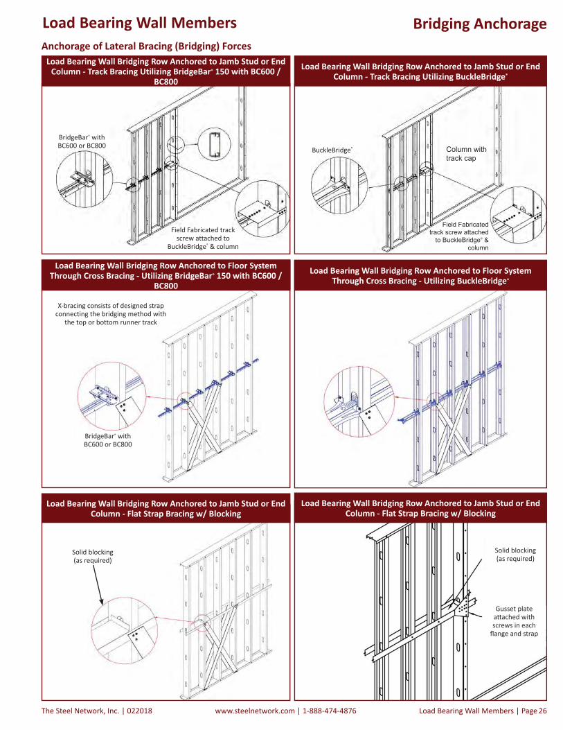
The Steel Network, Inc. | 022018 www.steelnetwork.com | 1-888-474-4876 Load Bearing Wall Members | Page 26
Bridging Anchorage
BuckleBridge®
Field Fabricated track screw attached
to BuckleBridge® & column
Column with track cap
Load Bearing Wall Bridging Row Anchored to Floor System Through Cross Bracing - Utilizing BridgeBar® 150 with BC600 /
BC800
BridgeBar® with BC600 or BC800
X-bracing consists of designed strap connecting the bridging method with
the top or bottom runner track
Load Bearing Wall Bridging Row Anchored to Jamb Stud or End Column - Track Bracing Utilizing BuckleBridge®
Solid blocking(as required)
Gusset plate a ached withscrews in each
fl ange and strap
Load Bearing Wall Bridging Row Anchored to Jamb Stud or End Column - Flat Strap Bracing w/ Blocking
Load Bearing Wall Bridging Row Anchored to Jamb Stud or End Column - Track Bracing Utilizing BridgeBar® 150 with BC600 /
BC800
Anchorage of Lateral Bracing (Bridging) Forces
Load Bearing Wall Bridging Row Anchored to Floor System Through Cross Bracing - Utilizing BuckleBridge®
Load Bearing Wall Bridging Row Anchored to Jamb Stud or End Column - Flat Strap Bracing w/ Blocking
Field Fabricated track screw attached to
BuckleBridge® & column
BridgeBar® with BC600 or BC800
Solid blocking(as required)
Load Bearing Wall Members
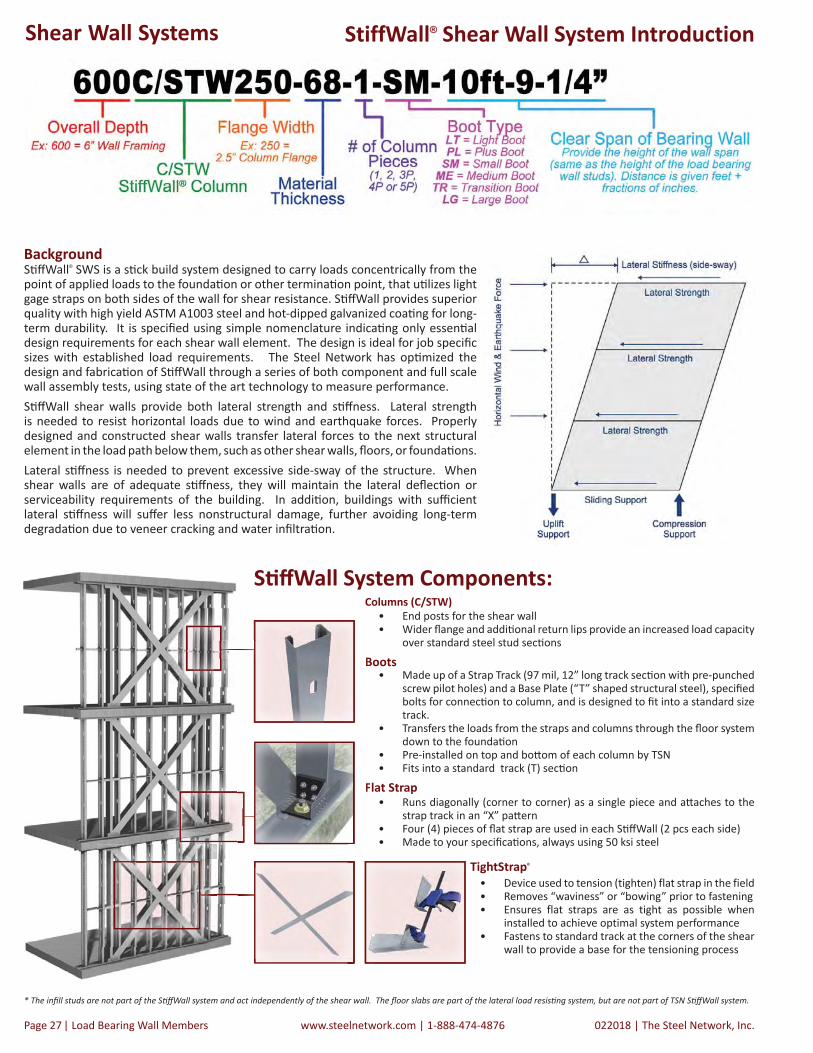
022018 | The Steel Network, Inc.www.steelnetwork.com | 1-888-474-4876Page | Load Bearing Wall Members 27
Background S ff Wall® SWS is a s ck build system designed to carry loads concentrically from the point of applied loads to the founda on or other termina on point, that u lizes light gage straps on both sides of the wall for shear resistance. S ff Wall provides superior quality with high yield ASTM A1003 steel and hot-dipped galvanized coa ng for long-term durability. It is specifi ed using simple nomenclature indica ng only essen al design requirements for each shear wall element. The design is ideal for job specifi c sizes with established load requirements. The Steel Network has op mized the design and fabrica on of S ff Wall through a series of both component and full scale wall assembly tests, using state of the art technology to measure performance.S ff Wall shear walls provide both lateral strength and s ff ness. Lateral strength is needed to resist horizontal loads due to wind and earthquake forces. Properly designed and constructed shear walls transfer lateral forces to the next structural element in the load path below them, such as other shear walls, fl oors, or founda ons.Lateral s ff ness is needed to prevent excessive side-sway of the structure. When shear walls are of adequate s ff ness, they will maintain the lateral defl ec on or serviceability requirements of the building. In addi on, buildings with suffi cient lateral s ff ness will suff er less nonstructural damage, further avoiding long-term degrada on due to veneer cracking and water infi ltra on.
StiffWall® Shear Wall System Introduction
S ff Wall System Components:
* The infi ll studs are not part of the S ff Wall system and act independently of the shear wall. The fl oor slabs are part of the lateral load resis ng system, but are not part of TSN S ff Wall system.
Columns (C/STW)• End posts for the shear wall• Wider fl ange and addi onal return lips provide an increased load capacity
over standard steel stud sec ons
Boots• Made up of a Strap Track (97 mil, 12” long track sec on with pre-punched
screw pilot holes) and a Base Plate (“T” shaped structural steel), specifi ed bolts for connec on to column, and is designed to fi t into a standard size track.
• Transfers the loads from the straps and columns through the fl oor system down to the founda on
• Pre-installed on top and bo om of each column by TSN• Fits into a standard track (T) sec on
Flat Strap• Runs diagonally (corner to corner) as a single piece and a aches to the
strap track in an “X” pa ern • Four (4) pieces of fl at strap are used in each S ff Wall (2 pcs each side)• Made to your specifi ca ons, always using 50 ksi steel
FFFll
CoC
BBBB
Made to your sspep
TightStrap® • Device used to tension (tighten) flat strap in the field• Removes “waviness” or “bowing” prior to fastening• Ensures flat straps are as tight as possible when
installed to achieve optimal system performance• Fastens to standard track at the corners of the shear
wall to provide a base for the tensioning process
Shear Wall Systems

The Steel Network, Inc. | 022018 www.steelnetwork.com | 1-888-474-4876 Load Bearing Wall Members | Page 28
StiffWall® Shear Wall System
Verifying Load PathsTracing and verifying load paths through a structure is crucial to protect engineering liability. Loads need to migrate from the roof, through the wall and fl oor systems, and terminate in the founda on. Shear wall systems transfer lateral loads from the member above (i.e. fl oor slab) to the member below (i.e. founda on). S ff Wall® provides a traceable, easily verifi able load path through the structure.
A Load transfers from the floor above through the floor connector, and to the StiffWall BootB From the Boot to the Strap Track*C From the Strap Track to the flat strap*D Through the flat strap to the Strap Track at opposite corner*E From the Strap Track to the BootF From the Boot to the floor/system or foundation below* The column section assumes the compression loads.* Uplift forces are transferred through the StiffWall® Boot through full bearing onto the SWS Boot Base Plate to the anchor.
Planning Shear WallsTo develop an effi cient shear wall layout several factors need to be considered:
S ff Wall® Benefi ts That Add Value• Templates are not required for hold-downs, elimina ng unrealis c fi eld procedures.• Designed and manufactured to meet the performance requirements of the project.• Sa sfi es maximum story dri requirements per IBC.• Only mill cer fi ed high strength steel is used.• Plywood sheathing with fastener schedules and/or CMU shear walls are eliminated.• Inspec on is limited to simple connec ons at corners.• Exceeds industry standards for sizes and loads.• Versa le design may be incorporated into steel, concrete and wood construc on• Tested for mul -story applica on and capable of carrying loads present in 10 story
buildings.• No welds or controlled inspec ons associated with welding.• Simplifi ed anchoring system through fl oors and at roof termina on.• Each component is selected to meet or exceed both strength and s ff ness requirements
of the applicable building code.• The strap system is on the outside of the wall to facilitate electrical and pipe work in
the wall cavity.• Allows 3 mes the window space of plywood braced structures. US Patent #6,892,504
• Height to Width aspect ratio guidelines should be observed in order to maximize effectiveness• Shear walls should be evenly distributed across the floor plan to reduce additional lateral
loads resulting from torsional effects on the floor plan• Shear Walls located in load bearing walls may use floor dead loads with the appropriate
load combination to offset uplift forces in the StiffWall• Walls must stack vertically from top floor of structure to anchorage point or foundation• Shear walls may overlap when the available wall space has been depleted
Shear Wall Systems

022018 | The Steel Network, Inc.www.steelnetwork.com | 1-888-474-4876Page | Load Bearing Wall Members 29
StiffWall® SWS Design
Step 2 - Select StiffWall® BootThe StiffWall Boot is a critical element enabling StiffWall to simultaneously resist higher loads and provide positive load transfer between elements, something conventional shear wall systems do not provide. Six different StiffWall Boots are available for accommodating changing loading requirements. Refer to the Boot Capacities table data to select the appropriate Boot to fit project conditions.
Step 3 - Determine Column-To-Boot Uplift Fastener Requirement Attaching to the StiffWall Column with #12 screws or 0.5” A325 bolts, the boot enhances construction efficiency by reducing the number of installed fasteners used in conventional flat strap shear walls. For uplift conditions, calculate the number of screws for the Light and Plus Boots by dividing the total uplift force by the single screw shear. For Small, Medium, Transition, and Large Boots, refer to the chart below for the number of fasteners to the column.
- Bolts referenced in table are ASTM F3125 Grade A325.- Refer to the Design Example for uplift requirements.- Allowable loads for screws are based on AISI S100 Specification, Section E4.3.- Maximum allowable load per (1) #12 screw in shear is equal to 0.849 kips, based on commercial screw data.- Allowable loads for bolts are based on AISI S100, Section E3.3.2.- Maximum allowable load per (1) A325 bolt in shear is equal to 4.42 kips, based on AISI S100, Section E3.4.* Compression loads are transferred via full column bearing onto boot.
Simple Steps to Design Shear Walls The following pages off er a guide for the design of the S ff Wall® shear wall system. In addi on, SteelSmart® System so ware is available (at www.steelsmartsystem.com) to select the op mal column, boot, strap and fasteners used in the installa on of S ff Wall. Contact The Steel Network for addi onal design informa on.Step 1 - Select S ff Wall® ColumnThis unique column contains an addi onal return lip to form a double lip, thus crea ng a stronger, more eff ec ve bearing sec on. The column is the main ver cal load-bearing transfer element in S ff Wall.Important Note:The StiffWall Boot must be used with the StiffWall Column. Standard stud (S) sections will not fit inside the StiffWall Boot or Strap Track.
Single Column Allowable Uplift Load (T2) (kips)
Column Thickness
Light / Plus Boot Small Boot Medium / Transition Boot Large Boot
(1) # 12 Screw
350, 362 & 400
550 & 600 800 350, 362 & 400 550 &
600 800 550 & 600 800 550 &
600 800 350, 362 & 400
550 & 600 800
(mils) (inch) (2) Bolts (4) Bolts (3)
Bolts(4)
Bolts(5)
Bolts (6) Bolts (8) Bolts (10) Bolts (7) Bolts (14) Bolts
33 0.0346 0.27 1.71 3.43 3.43 2.57 3.43 4.13 5.14 5.14 6.85 6.85 7.50 8.56 5.27 9.78 11.3043 0.0451 0.41 2.30 4.59 4.59 3.45 4.59 5.38 6.89 6.89 9.19 9.19 9.77 11.48 6.87 12.74 14.7254 0.0566 0.57 2.97 5.94 5.94 4.46 5.94 6.75 8.91 8.91 11.88 11.88 12.26 14.75 8.62 15.99 18.4868 0.0713 0.78 3.88 7.77 7.77 5.83 7.77 8.51 11.65 11.65 15.54 15.54 15.45 18.58 10.86 20.15 23.2897 0.1017 0.78 5.96 11.92 11.92 8.94 11.92 12.13 17.88 17.88 23.84 23.84 22.04 26.50 15.48 28.73 33.20118 0.1242 0.78 7.66 14.64 15.32 11.49 15.32 14.82 22.98 22.98 29.36 30.64 26.91 32.36 18.91 35.09 40.55
Back-to-Back and Built-Up Column Allowable Uplift Load (T2) (kips)
Column Thickness
Light / Plus Boot Small Boot Medium / Transition Boot Large Boot
(1) # 12 Screw
350, 362 & 400
550 & 600 800 350, 362 & 400 550 &
600 800 550 & 600 800 550 &
600 800 350, 362 & 400
550 & 600 800
(mils) (inch) (2) Bolts (4) Bolts (3)
Bolts(4)
Bolts(5)
Bolts (6) Bolts (8) Bolts (10) Bolts (7) Bolts (14) Bolts
33 0.0346 N / A 3.43 6.85 6.85 5.14 6.85 8.26 10.28 10.28 13.70 13.70 14.99 17.13 10.54 19.55 22.59
43 0.0451 N / A 4.59 9.19 9.19 6.89 9.19 10.76 13.78 13.78 18.37 18.37 19.54 22.97 13.73 25.49 29.45
54 0.0566 N / A 5.94 11.88 11.88 8.91 11.88 13.51 17.82 17.82 23.77 23.77 24.53 29.50 17.23 31.98 36.96
68 0.0713 N / A 7.77 15.54 15.54 11.65 15.54 17.01 23.31 23.31 31.08 31.08 30.90 37.16 21.71 40.29 46.55
97 0.1017 N / A 10.60 21.21 21.21 15.90 21.21 24.27 31.81 31.81 42.41 42.41 44.07 53.00 30.97 57.47 66.40
118 0.1242 N / A 10.60 21.21 21.21 15.90 21.21 26.51 31.81 31.81 42.41 42.41 53.01 53.01 37.11 70.18 74.22
a on.
Shear Wall Systems
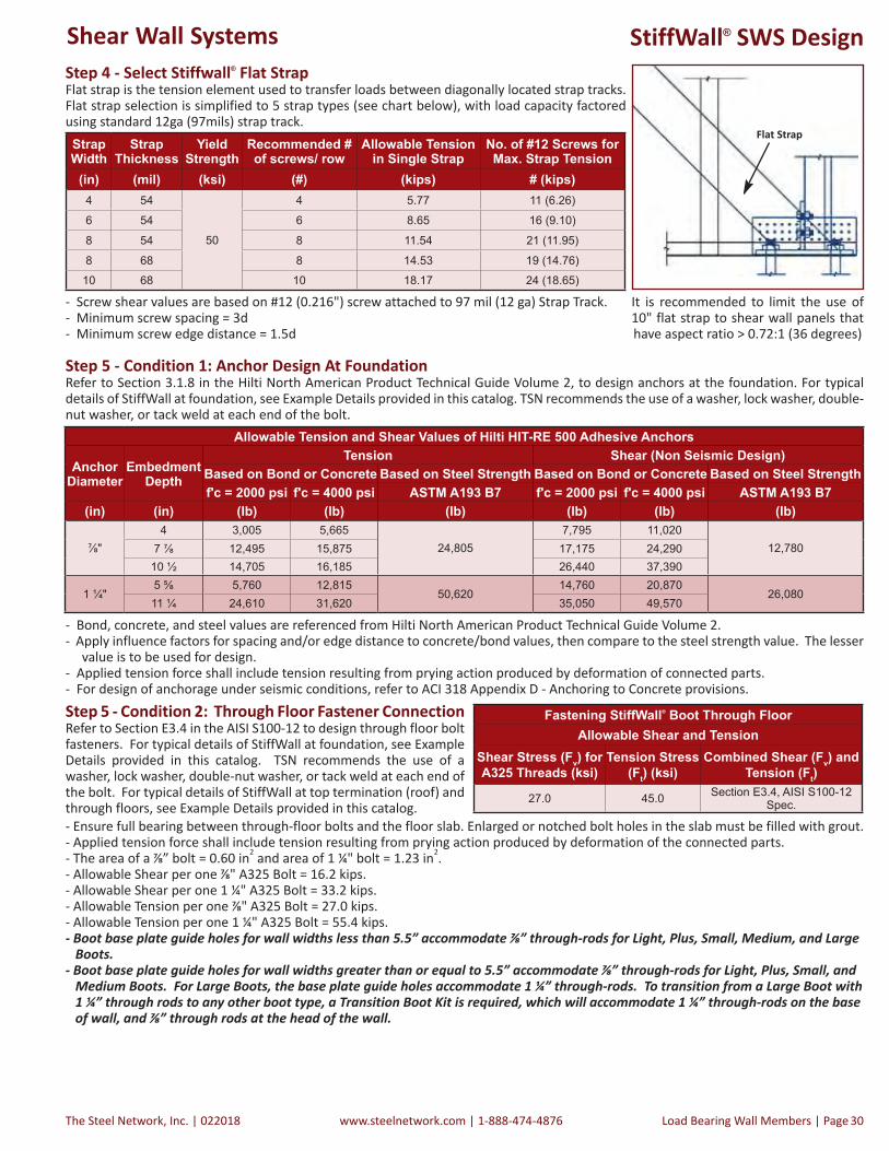
The Steel Network, Inc. | 022018 www.steelnetwork.com | 1-888-474-4876 Load Bearing Wall Members | Page 30
Step 5 - Condition 1: Anchor Design At Foundation Refer to Section 3.1.8 in the Hilti North American Product Technical Guide Volume 2, to design anchors at the foundation. For typical details of StiffWall at foundation, see Example Details provided in this catalog. TSN recommends the use of a washer, lock washer, double-nut washer, or tack weld at each end of the bolt.
- Bond, concrete, and steel values are referenced from Hilti North American Product Technical Guide Volume 2.- Apply influence factors for spacing and/or edge distance to concrete/bond values, then compare to the steel strength value. The lesser value is to be used for design.- Applied tension force shall include tension resulting from prying action produced by deformation of connected parts.- For design of anchorage under seismic conditions, refer to ACI 318 Appendix D - Anchoring to Concrete provisions.Step 5 - Condition 2: Through Floor Fastener Connection Refer to Section E3.4 in the AISI S100-12 to design through floor bolt fasteners. For typical details of StiffWall at foundation, see Example Details provided in this catalog. TSN recommends the use of a washer, lock washer, double-nut washer, or tack weld at each end of the bolt. For typical details of StiffWall at top termination (roof) and through floors, see Example Details provided in this catalog.
Fastening StiffWall® Boot Through FloorAllowable Shear and Tension
Shear Stress (Fv) for A325 Threads (ksi)
Tension Stress(Ft) (ksi)
Combined Shear (Fv) andTension (Ft)
27.0 45.0 Section E3.4, AISI S100-12 Spec.
StiffWall® SWS DesignStep 4 - Select Stiffwall® Flat Strap Flat strap is the tension element used to transfer loads between diagonally located strap tracks. Flat strap selection is simplified to 5 strap types (see chart below), with load capacity factored using standard 12ga (97mils) strap track.
- Screw shear values are based on #12 (0.216") screw attached to 97 mil (12 ga) Strap Track.- Minimum screw spacing = 3d - Minimum screw edge distance = 1.5d
Flat Strap
Allowable Tension and Shear Values of Hilti HIT-RE 500 Adhesive Anchors
Anchor Diameter
Embedment Depth
Tension Shear (Non Seismic Design)Based on Bond or Concrete Based on Steel Strength Based on Bond or Concrete Based on Steel Strengthf'c = 2000 psi f'c = 4000 psi ASTM A193 B7 f'c = 2000 psi f'c = 4000 psi ASTM A193 B7
(in) (in) (lb) (lb) (lb) (lb) (lb) (lb)
⅞"4 3,005 5,665
24,8057,795 11,020
12,7807 ⅞ 12,495 15,875 17,175 24,29010 ½ 14,705 16,185 26,440 37,390
1 ¼"5 ⅝ 5,760 12,815
50,62014,760 20,870
26,08011 ¼ 24,610 31,620 35,050 49,570
Strap Width
Strap Thickness
Yield Strength
Recommended # of screws/ row
Allowable Tension in Single Strap
No. of #12 Screws for Max. Strap Tension
(in) (mil) (ksi) (#) (kips) # (kips)4 54
50
4 5.77 11 (6.26)
6 54 6 8.65 16 (9.10)
8 54 8 11.54 21 (11.95)
8 68 8 14.53 19 (14.76)10 68 10 18.17 24 (18.65)
It is recommended to limit the use of 10" flat strap to shear wall panels that have aspect ratio > 0.72:1 (36 degrees)
- Ensure full bearing between through-floor bolts and the floor slab. Enlarged or notched bolt holes in the slab must be filled with grout.- Applied tension force shall include tension resulting from prying action produced by deformation of the connected parts.- The area of a ⅞” bolt = 0.60 in2 and area of 1 ¼" bolt = 1.23 in2.- Allowable Shear per one ⅞" A325 Bolt = 16.2 kips.- Allowable Shear per one 1 ¼" A325 Bolt = 33.2 kips.- Allowable Tension per one ⅞" A325 Bolt = 27.0 kips.- Allowable Tension per one 1 ¼" A325 Bolt = 55.4 kips.- Boot base plate guide holes for wall widths less than 5.5” accommodate ⅞” through-rods for Light, Plus, Small, Medium, and Large Boots.- Boot base plate guide holes for wall widths greater than or equal to 5.5” accommodate ⅞” through-rods for Light, Plus, Small, and Medium Boots. For Large Boots, the base plate guide holes accommodate 1 ¼” through-rods. To transition from a Large Boot with 1 ¼” through rods to any other boot type, a Transition Boot Kit is required, which will accommodate 1 ¼” through-rods on the base of wall, and ⅞” through rods at the head of the wall.
Shear Wall Systems

022018 | The Steel Network, Inc.www.steelnetwork.com | 1-888-474-4876Page | Load Bearing Wall Members 31
Pre-Assembled Columns/Boots
The added value of the pre-installed boots minimizes tolerance issues during erection. Simply specify the clear span of the bearing wall system and TSN will ship the Column/Boot assembly to meet the given wall height at a tolerance of +0/-⅛”.
Order Informa onS ff Walls consist of two Column/Boot Assemblies (at each end post) and Flat Strap (2 sides of X-bracing). The S ff Wall fi ts into or is embedded into the load bearing and non-load bearing walls. Do your stud take off as normal and order the Column/Boot Assembly and the Flat Strap as separate items. When ordering columns, determine the height of the bearing wall. TSN will size the S ff Wall Column/Boot Assembly factoring in the dimensions of the boots at top and bo om. Each column is shipped with the boots pre-a ached at the top and bo om as shown in the image to the right.
Nomenclature
Shear Wall Systems
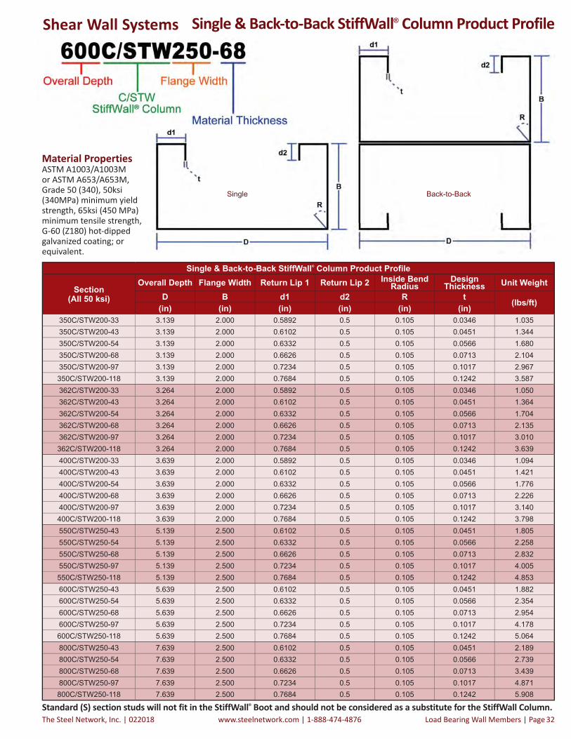
The Steel Network, Inc. | 022018 www.steelnetwork.com | 1-888-474-4876 Load Bearing Wall Members | Page 32
Single & Back-to-Back StiffWall® Column Product Profile
Single & Back-to-Back StiffWall® Column Product Profile
Section(All 50 ksi)
Overall Depth Flange Width Return Lip 1 Return Lip 2 Inside Bend Radius
Design Thickness Unit Weight
D B d1 d2 R t (lbs/ft)(in) (in) (in) (in) (in) (in)350C/STW200-33 3.139 2.000 0.5892 0.5 0.105 0.0346 1.035350C/STW200-43 3.139 2.000 0.6102 0.5 0.105 0.0451 1.344350C/STW200-54 3.139 2.000 0.6332 0.5 0.105 0.0566 1.680350C/STW200-68 3.139 2.000 0.6626 0.5 0.105 0.0713 2.104350C/STW200-97 3.139 2.000 0.7234 0.5 0.105 0.1017 2.967350C/STW200-118 3.139 2.000 0.7684 0.5 0.105 0.1242 3.587362C/STW200-33 3.264 2.000 0.5892 0.5 0.105 0.0346 1.050362C/STW200-43 3.264 2.000 0.6102 0.5 0.105 0.0451 1.364362C/STW200-54 3.264 2.000 0.6332 0.5 0.105 0.0566 1.704362C/STW200-68 3.264 2.000 0.6626 0.5 0.105 0.0713 2.135362C/STW200-97 3.264 2.000 0.7234 0.5 0.105 0.1017 3.010362C/STW200-118 3.264 2.000 0.7684 0.5 0.105 0.1242 3.639400C/STW200-33 3.639 2.000 0.5892 0.5 0.105 0.0346 1.094400C/STW200-43 3.639 2.000 0.6102 0.5 0.105 0.0451 1.421400C/STW200-54 3.639 2.000 0.6332 0.5 0.105 0.0566 1.776400C/STW200-68 3.639 2.000 0.6626 0.5 0.105 0.0713 2.226400C/STW200-97 3.639 2.000 0.7234 0.5 0.105 0.1017 3.140400C/STW200-118 3.639 2.000 0.7684 0.5 0.105 0.1242 3.798550C/STW250-43 5.139 2.500 0.6102 0.5 0.105 0.0451 1.805550C/STW250-54 5.139 2.500 0.6332 0.5 0.105 0.0566 2.258550C/STW250-68 5.139 2.500 0.6626 0.5 0.105 0.0713 2.832550C/STW250-97 5.139 2.500 0.7234 0.5 0.105 0.1017 4.005550C/STW250-118 5.139 2.500 0.7684 0.5 0.105 0.1242 4.853600C/STW250-43 5.639 2.500 0.6102 0.5 0.105 0.0451 1.882600C/STW250-54 5.639 2.500 0.6332 0.5 0.105 0.0566 2.354600C/STW250-68 5.639 2.500 0.6626 0.5 0.105 0.0713 2.954600C/STW250-97 5.639 2.500 0.7234 0.5 0.105 0.1017 4.178600C/STW250-118 5.639 2.500 0.7684 0.5 0.105 0.1242 5.064800C/STW250-43 7.639 2.500 0.6102 0.5 0.105 0.0451 2.189800C/STW250-54 7.639 2.500 0.6332 0.5 0.105 0.0566 2.739800C/STW250-68 7.639 2.500 0.6626 0.5 0.105 0.0713 3.439800C/STW250-97 7.639 2.500 0.7234 0.5 0.105 0.1017 4.871800C/STW250-118 7.639 2.500 0.7684 0.5 0.105 0.1242 5.908
Material PropertiesASTM A1003/A1003M or ASTM A653/A653M, Grade 50 (340), 50ksi (340MPa) minimum yield strength, 65ksi (450 MPa) minimum tensile strength, G-60 (Z180) hot-dipped galvanized coating; or equivalent.
Standard (S) section studs will not fit in the StiffWall® Boot and should not be considered as a substitute for the StiffWall Column.
Shear Wall Systems
Single Back-to-Back

022018 | The Steel Network, Inc.www.steelnetwork.com | 1-888-474-4876Page | Load Bearing Wall Members 33
Built-Up StiffWall® Column Product ProfileMaterial PropertiesASTM A1003/A1003M or ASTM A653/A653M, Grade 50 (340), 50ksi (340MPa) minimum yield strength, 65ksi (450 MPa) minimum tensile strength, G-60 (Z180) hot-dipped galvanized coating; or equivalent.
Shear Wall Systems

The Steel Network, Inc. | 022018 www.steelnetwork.com | 1-888-474-4876 Load Bearing Wall Members | Page 34
Built-Up StiffWall® Column Product ProfileBuilt-Up StiffWall® Column Product Profile
Depth(in)
Section(All 50 ksi) Components
Overall Depth Flange Width Return Lip 1 Design Thickness Unit Weight
D B d1 t(lbs/ft)
(in) (in) (in) (in)
350
(3P) 350C/STW200-97(2) 350C/STW200-97 3.139 2.000 0.7234 0.1017
7.793275T150-97 2.750 1.500 N/A 0.1017
(3P) 350C/STW200-118(2) 350C/STW200-118 3.139 2.000 0.7684 0.1242
9.032275T150-97 2.750 1.500 N/A 0.1017
362
(3P) 362C/STW200-97(2) 362C/STW200-97 3.264 2.000 0.7234 0.1017
7.880275T150-97 2.750 1.500 N/A 0.1017
(3P) 362C/STW200-118(2) 362C/STW200-118 3.264 2.000 0.7684 0.1242
9.138275T150-97 2.750 1.500 N/A 0.1017
(4P) 362C/STW200-97
(2) 362*C/STW200-97 3.029 2.000 0.7234 0.1017
9.841275T150-97 2.750 1.500 N/A 0.1017
326T162-97 3.264 1.625 N/A 0.1017
(4P) 362C/STW200-118
(2) 362*C/STW200-118 3.029 2.000 0.7684 0.1242
11.156275T150-97 2.750 1.500 N/A 0.1017
326T162-97 3.264 1.625 N/A 0.1017
400
(3P) 400C/STW200-97(2) 400C/STW200-97 3.639 2.000 0.7234 0.1017
8.139275T150-97 2.750 1.500 N/A 0.1017
(3P) 400C/STW200-118(2) 400C/STW200-118 3.639 2.000 0.7684 0.1242
9.454275T150-97 2.750 1.500 N/A 0.1017
(4P) 400C/STW200-97
(2) 400*C/STW200-97 3.404 2.000 0.7234 0.1017
10.230275T150-97 2.750 1.500 N/A 0.1017
364T162-97 3.639 1.625 N/A 0.1017
(4P) 400C/STW200-118
(2) 400*C/STW200-118 3.404 2.000 0.7684 0.1242
11.509275T150-97 2.750 1.500 N/A 0.1017
364T162-97 3.639 1.625 N/A 0.1017
550
(3P) 550C/STW250-97(2) 550C/STW250-97 5.139 2.500 0.7234 0.1017
10.604400S162-97 4.000 1.625 0.5000 0.1017
(3P) 550C/STW250-118(2) 550C/STW250-118 5.139 2.500 0.7684 0.1242
12.299400S162-97 4.000 1.625 0.5000 0.1017
Shear Wall Systems
* Overall Depth (D) varies from Single and Back-to-Back sections

022018 | The Steel Network, Inc.www.steelnetwork.com | 1-888-474-4876Page | Load Bearing Wall Members 35
Built-Up StiffWall® Column Product Profile
Depth(in)
Section(All 50 ksi) Components
Overall Depth Flange Width Return Lip 1 Design Thickness Unit Weight
D B d1 t(lbs/ft)
(in) (in) (in) (in)
600
(3P) 600C/STW250-97(2) 600C/STW250-97 5.639 2.500 0.7234 0.1017
10.950400S162-97 4.000 1.625 0.5000 0.1017
(3P) 600C/STW250-118(2) 600C/STW250-118 5.639 2.500 0.7684 0.1242
12.721400S162-97 4.000 1.625 0.5000 0.1017
(4P) 600C/STW250-97(2) 600*C/STW250-97 5.404 2.500 0.7234 0.1017
15.704(2) 564SGP225-97 5.639 2.250 N/A 0.1017
(4P) 600C/STW250-118(2) 600*C/STW250-118 5.404 2.500 0.7684 0.1242
17.439(2) 564SGP225-97 5.639 2.250 N/A 0.1017
(5P) 600C/STW250-97
(2) 600*C/STW250-97 5.404 2.500 0.7234 0.1017
18.297(2) 564SGP225-97 5.639 2.250 N/A 0.1017
400S162-97 4.000 1.625 0.5000 0.1017
(5P) 600C/STW250-118
(2) 600*C/STW250-118 5.404 2.500 0.7684 0.1242
20.032(2) 564SGP225-97 5.639 2.250 N/A 0.1017
400S162-97 4.000 1.625 0.5000 0.1017
800
(3P) 800C/STW250-97(2) 800C/STW250-97 7.639 2.500 0.7234 0.1017
13.373600S200-97 6.000 2.000 0.6250 0.1017
(3P) 800C/STW250-118(2) 800C/STW250-118 7.639 2.500 0.7684 0.1242
15.447600S200-97 6.000 2.000 0.6250 0.1017
(4P) 800C/STW250-97(2) 800*C/STW250-97 7.404 2.500 0.7234 0.1017
18.473(2) 764SGP225-97 7.639 2.250 N/A 0.1017
(4P) 800C/STW250-118(2) 800*C/STW250-118 7.404 2.500 0.7684 0.1242
20.511(2) 764SGP225-97 7.639 2.250 N/A 0.1017
(5P) 800C/STW250-97
(2) 800*C/STW250-97 7.404 2.500 0.7234 0.1017
21.758(2) 764SGP225-97 7.639 2.250 N/A 0.1017
600S162-97 6.000 1.625 0.5000 0.1017
(5P) 800C/STW250-118
(2) 800*C/STW250-118 7.404 2.500 0.7684 0.1242
23.797(2) 764SGP225-97 7.639 2.250 N/A 0.1017
600S162-97 6.000 1.625 0.5000 0.1017
Built-Up StiffWall® Column Product Profile
* Overall Depth (D) varies from Single and Back-to-Back sections

The Steel Network, Inc. | 022018 www.steelnetwork.com | 1-888-474-4876 Load Bearing Wall Members | Page 36
Single StiffWall® Column Section Properties
Single StiffWall® Column Section Properties
Section(All 50 ksi)
Gross Properties Effective Properties 50 ksi
Area Ix Sx Rx Iy Ry Jx1000 Cw Ro Xo mß
Ix Sx (net)
(in2) (in4) (in3) (in) (in4) (in) (in4) (in6) (in) (in) (in) (in4) (in3)350C/STW200-33 0.304 0.489 0.312 1.268 0.185 0.781 0.121 0.607 2.524 -2.038 1.209 0.348 0.476 0.248
350C/STW200-43 0.395 0.629 0.401 1.262 0.239 0.777 0.268 0.787 2.515 -2.032 1.206 0.347 0.629 0.355
350C/STW200-54 0.494 0.777 0.495 1.255 0.295 0.774 0.527 0.982 2.506 -2.026 1.203 0.346 0.777 0.462
350C/STW200-68 0.618 0.960 0.612 1.246 0.366 0.769 1.048 1.226 2.493 -2.018 1.199 0.345 0.960 0.599
350C/STW200-97 0.872 1.315 0.838 1.228 0.502 0.759 3.006 1.718 2.467 -2.001 1.190 0.342 1.315 0.819
350C/STW200-118 1.054 1.555 0.991 1.215 0.595 0.752 5.402 2.065 2.448 -1.988 1.183 0.341 1.555 0.969
362C/STW200-33 0.309 0.535 0.328 1.317 0.188 0.781 0.123 0.644 2.531 -2.016 1.198 0.366 0.522 0.260
362C/STW200-43 0.401 0.689 0.422 1.311 0.242 0.778 0.272 0.834 2.523 -2.010 1.195 0.365 0.689 0.373
362C/STW200-54 0.501 0.852 0.522 1.304 0.300 0.774 0.535 1.040 2.513 -2.004 1.192 0.364 0.852 0.486
362C/STW200-68 0.627 1.053 0.645 1.295 0.371 0.769 1.063 1.299 2.501 -1.996 1.188 0.363 1.053 0.633
362C/STW200-97 0.885 1.443 0.884 1.277 0.510 0.760 3.050 1.817 2.475 -1.979 1.179 0.361 1.443 0.867
362C/STW200-118 1.069 1.709 1.047 1.264 0.605 0.752 5.481 2.183 2.455 -1.966 1.172 0.359 1.709 1.026
400C/STW200-33 0.322 0.689 0.379 1.464 0.197 0.782 0.128 0.764 2.562 -1.952 1.167 0.420 0.673 0.297
400C/STW200-43 0.418 0.887 0.488 1.458 0.253 0.779 0.283 0.989 2.553 -1.946 1.164 0.419 0.887 0.426
400C/STW200-54 0.522 1.099 0.604 1.451 0.314 0.775 0.557 1.232 2.544 -1.940 1.161 0.418 1.099 0.556
400C/STW200-68 0.654 1.360 0.748 1.442 0.388 0.770 1.108 1.536 2.531 -1.932 1.157 0.417 1.360 0.732
400C/STW200-97 0.923 1.871 1.028 1.424 0.534 0.761 3.181 2.143 2.505 -1.915 1.149 0.415 1.871 1.013
400C/STW200-118 1.116 2.220 1.220 1.411 0.633 0.753 5.719 2.569 2.485 -1.903 1.142 0.414 2.220 1.201
550C/STW250-43 0.530 2.281 0.888 2.074 0.491 0.962 0.360 3.069 3.175 -2.203 1.321 0.518 2.258 0.748
550C/STW250-54 0.663 2.835 1.103 2.067 0.609 0.958 0.708 3.821 3.165 -2.197 1.318 0.518 2.835 0.952
550C/STW250-68 0.832 3.527 1.373 2.059 0.757 0.954 1.410 4.763 3.153 -2.189 1.314 0.518 3.527 1.240
550C/STW250-97 1.177 4.902 1.908 2.041 1.050 0.944 4.058 6.644 3.127 -2.173 1.306 0.517 4.902 1.873
550C/STW250-118 1.426 5.864 2.282 2.028 1.253 0.937 7.308 7.966 3.108 -2.161 1.299 0.517 5.864 2.282
600C/STW250-43 0.553 2.825 1.002 2.261 0.508 0.958 0.375 3.671 3.253 -2.134 1.288 0.570 2.802 0.849
600C/STW250-54 0.692 3.514 1.246 2.254 0.630 0.955 0.739 4.568 3.244 -2.128 1.285 0.569 3.514 1.079
600C/STW250-68 0.868 4.376 1.552 2.245 0.783 0.950 1.471 5.692 3.231 -2.121 1.281 0.569 4.376 1.404
600C/STW250-97 1.228 6.093 2.161 2.228 1.086 0.941 4.233 7.932 3.205 -2.104 1.273 0.569 6.093 2.121
600C/STW250-118 1.488 7.298 2.588 2.215 1.297 0.934 7.626 9.503 3.186 -2.092 1.266 0.569 7.298 2.588
800C/STW250-43 0.643 5.723 1.498 2.983 0.563 0.936 0.436 6.814 3.661 -1.904 1.176 0.729 5.709 1.169
800C/STW250-54 0.805 7.131 1.867 2.976 0.700 0.932 0.860 8.472 3.651 -1.898 1.173 0.730 7.131 1.627
800C/STW250-68 1.011 8.900 2.330 2.968 0.870 0.928 1.712 10.544 3.639 -1.890 1.169 0.730 8.900 2.121
800C/STW250-97 1.431 12.452 3.260 2.950 1.207 0.918 4.934 14.662 3.613 -1.873 1.160 0.731 12.452 3.199
800C/STW250-118 1.736 14.968 3.919 2.936 1.442 0.911 8.897 17.540 3.594 -1.861 1.153 0.732 14.968 3.919
Important Notes1. Section properties and capacities are calculated in accordance with AISI S100.2. Tabulated gross properties are based on the full-unreduced cross section of the studs,
away from punchouts.3. Effective section properties incorporate the strength increase from the cold-work of
forming as applicable per AISI S100 Sec. A7.2.4. Net effective section properties are calculated at a cross section through the punchout.5. For deflection calculations, use the effective moment of inertia.6. The effective moment of inertia for deflection is calculated at a stress which results in a section modulus such that the stress times
the section modulus at that stress is equal to the allowable moment.7. The StiffWall Column must be used with the StiffWall Boot. Standard (S) sections will not fit inside the StiffWall Boot or Strap Track.
Shear Wall Systems

022018 | The Steel Network, Inc.www.steelnetwork.com | 1-888-474-4876Page | Load Bearing Wall Members 37
Single StiffWall® Column Axial Load TablesImportant Notes1. Allowable loads are based on specified weak axis and torsional bracing
for axial load calculation.2. Sections are punched with a standard punch-out 1.5" wide located
along the centerline of the web 24" o.c.3. Allowable loads are based on a punched section for axial load calculation.4. The allowable axial strength for distortional buckling is based on an
assumed k = 0.5. Weak axis and torsional bracing should have sufficient stiffness and
strength to resist the axial load.6. Strength increase due to cold work of forming is incorporated in
calculating allowable loads as per AISI S100, Sec. A7.2.7. The StiffWall Column must be used with the StiffWall Boot. Standard (S) sections will not fit inside the StiffWall Boot or Strap Track.8. StiffWall Columns are delivered to the job site with Boots pre-attached at the top and bottom for fast installation.
Single Section: Axial Compression Load (kips)
Section(All 50 ksi)
Maximum Unbraced Length = 48" Maximum Unbraced Length = 60" Max Unbraced Length = Full HeightSW Column Height (ft) SW Column Height (ft) SW Column Height (ft)
9 10 12 14 9 10 12 14 9 10 12 14350C/STW200-33 2.64 2.41 1.95 1.57 2.12 1.96 1.64 1.37 0.91 0.75 0.54 0.42
350C/STW200-43 3.56 3.18 2.53 2.03 2.80 2.57 2.14 1.78 1.25 1.04 0.76 0.60
350C/STW200-54 4.47 3.98 3.15 2.52 3.55 3.25 2.70 2.23 1.66 1.40 1.05 0.84
350C/STW200-68 5.63 5.00 3.95 3.15 4.55 4.14 3.41 2.81 2.29 1.95 1.51 1.23
350C/STW200-97 8.08 7.14 5.57 4.40 6.75 6.09 4.94 4.02 3.96 3.45 2.76 2.08
350C/STW200-118 9.91 8.72 6.74 5.30 8.51 7.62 6.09 4.91 5.53 4.83 3.35 2.46
362C/STW200-33 2.78 2.56 2.09 1.71 2.26 2.09 1.77 1.49 0.97 0.80 0.57 0.44
362C/STW200-43 3.83 3.45 2.75 2.21 3.02 2.78 2.33 1.94 1.32 1.10 0.81 0.63
362C/STW200-54 4.81 4.32 3.44 2.76 3.83 3.51 2.93 2.43 1.76 1.48 1.11 0.89
362C/STW200-68 6.06 5.44 4.30 3.44 4.90 4.47 3.71 3.06 2.42 2.06 1.59 1.30
362C/STW200-97 8.69 7.76 6.08 4.82 7.28 6.59 5.37 4.38 4.18 3.64 2.89 2.12
362C/STW200-118 10.66 9.49 7.37 5.80 9.17 8.24 6.63 5.35 5.84 4.93 3.42 2.51
400C/STW200-33 3.15 2.95 2.53 2.09 2.62 2.47 2.13 1.82 1.14 0.94 0.68 0.52
400C/STW200-43 4.44 4.12 3.42 2.81 3.61 3.36 2.89 2.46 1.56 1.29 0.94 0.73
400C/STW200-54 5.75 5.33 4.38 3.53 4.70 4.35 3.68 3.08 2.06 1.73 1.29 1.03
400C/STW200-68 7.33 6.73 5.49 4.42 6.01 5.54 4.66 3.89 2.82 2.39 1.84 1.50
400C/STW200-97 10.48 9.60 7.77 6.20 8.88 8.16 6.76 5.57 4.83 4.21 3.05 2.24
400C/STW200-118 12.83 11.73 9.43 7.49 11.14 10.23 8.36 6.83 6.42 5.20 3.61 2.65
550C/STW250-43 6.34 6.20 5.84 5.39 5.76 5.64 5.30 4.89 2.84 2.37 1.74 1.35
550C/STW250-54 8.32 8.14 7.83 7.30 7.76 7.61 7.18 6.53 3.80 3.19 2.37 1.85
550C/STW250-68 11.94 11.55 10.62 9.57 10.51 10.20 9.46 8.59 5.19 4.38 3.25 2.54
550C/STW250-97 18.21 17.59 16.15 14.50 16.18 15.68 14.50 13.12 8.40 7.11 5.43 4.41
550C/STW250-118 23.00 22.19 20.19 17.89 20.47 19.76 18.09 16.17 11.16 9.59 7.45 5.48
600C/STW250-43 6.59 6.46 6.17 5.80 6.03 5.93 5.69 5.34 3.11 2.60 1.91 1.48
600C/STW250-54 8.66 8.49 8.14 7.81 8.02 7.94 7.68 7.25 4.17 3.50 2.61 2.05
600C/STW250-68 12.38 12.18 11.48 10.55 11.20 10.95 10.32 9.57 5.70 4.81 3.63 2.87
600C/STW250-97 19.32 18.81 17.57 16.12 17.32 16.91 15.93 14.72 9.48 8.02 6.09 4.78
600C/STW250-118 24.55 23.88 22.27 20.38 22.14 21.60 20.30 18.71 12.54 10.73 7.76 5.70
800C/STW250-43 7.13 7.08 6.94 6.74 6.64 6.60 6.49 6.35 3.93 3.27 2.40 1.86
800C/STW250-54 9.44 9.37 9.17 8.90 8.76 8.71 8.56 8.36 5.25 4.40 3.27 2.56
800C/STW250-68 13.47 13.37 13.10 12.74 12.59 12.52 12.34 12.03 7.13 6.02 4.51 3.46
800C/STW250-97 21.88 21.65 21.03 20.20 19.95 19.78 19.34 18.73 11.40 9.51 6.95 5.32
800C/STW250-118 28.08 27.78 26.98 25.90 25.71 25.49 24.91 24.11 14.46 12.06 8.77 6.47
Shear Wall Systems

The Steel Network, Inc. | 022018 www.steelnetwork.com | 1-888-474-4876 Load Bearing Wall Members | Page 38
Back-to-Back Axial Load Tables
Back-to-Back (Fastener Spacing = 24 in): Axial Compression Load (kips)
Section(Back-to-Back)
Maximum Unbraced Length = 48" Maximum Unbraced Length = 60" Max Unbraced Length = Full HeightSW Column Height (ft) SW Column Height (ft) SW Column Height (ft)
9 10 12 14 9 10 12 14 9 10 12 14(2) 350C/STW200-33 7.40 6.71 5.34 4.06 7.40 6.71 5.34 4.06 4.51 3.76 2.73 2.10
(2) 350C/STW200-43 10.62 9.45 7.13 5.24 10.62 9.45 7.13 5.24 6.28 5.25 3.90 3.09
(2) 350C/STW200-54 13.33 11.77 8.80 6.47 13.33 11.77 8.80 6.47 8.48 7.18 5.50 4.48
(2) 350C/STW200-68 16.56 14.59 10.86 7.98 16.56 14.59 10.86 7.98 11.83 10.27 8.15 6.50
(2) 350C/STW200-97 22.92 20.11 14.84 10.90 22.92 20.11 14.84 10.90 19.70 16.97 12.21 9.11
(2) 350C/STW200-118 27.32 23.91 17.52 12.87 27.32 23.91 17.52 12.87 23.71 20.42 14.69 10.97
(2) 362C/STW200-33 7.65 7.00 5.68 4.40 7.65 7.00 5.68 4.40 4.56 3.80 2.78 2.14
(2) 362C/STW200-43 11.03 9.95 7.75 5.75 11.03 9.95 7.75 5.75 6.40 5.34 3.96 3.13
(2) 362C/STW200-54 14.11 12.57 9.62 7.11 14.11 12.57 9.62 7.11 8.62 7.29 5.56 4.52
(2) 362C/STW200-68 17.54 15.60 11.89 8.78 17.54 15.60 11.89 8.78 11.98 10.38 8.20 6.52
(2) 362C/STW200-97 24.33 21.56 16.31 12.01 24.33 21.56 16.31 12.01 19.86 17.07 12.25 9.15
(2) 362C/STW200-118 29.04 25.68 19.31 14.19 29.04 25.68 19.31 14.19 23.91 20.55 14.75 11.01
(2) 400C/STW200-33 8.29 7.72 6.53 5.35 8.29 7.72 6.53 5.35 4.66 3.89 2.87 2.24
(2) 400C/STW200-43 12.04 11.18 9.21 7.27 12.04 11.18 9.21 7.27 6.60 5.56 4.13 3.24
(2) 400C/STW200-54 15.77 14.45 11.81 9.25 15.77 14.45 11.81 9.25 9.00 7.58 5.73 4.62
(2) 400C/STW200-68 20.30 18.48 14.84 11.44 20.30 18.48 14.84 11.44 12.40 10.67 8.34 6.59
(2) 400C/STW200-97 28.30 25.68 20.51 15.70 28.30 25.68 20.51 15.70 20.33 17.36 12.39 9.24
(2) 400C/STW200-118 33.90 30.71 24.43 18.60 33.90 30.71 24.43 18.60 24.48 20.90 14.92 11.13
(2) 550C/STW250-43 14.58 14.16 13.22 12.19 13.93 13.93 13.22 12.19 9.37 8.02 5.90 4.59
(2) 550C/STW250-54 19.21 18.63 17.33 16.08 18.37 18.37 17.33 16.08 12.67 10.82 8.08 6.37
(2) 550C/STW250-68 27.22 26.38 24.66 22.40 26.12 26.12 24.66 22.40 17.18 14.93 11.35 9.12
(2) 550C/STW250-97 43.71 41.89 37.94 33.76 41.86 41.86 37.94 33.76 28.16 25.24 20.00 16.44
(2) 550C/STW250-118 54.95 52.61 47.56 42.06 53.18 52.61 47.56 42.06 37.07 33.67 27.79 20.75
(2) 600C/STW250-43 14.76 14.55 13.74 12.84 14.02 14.02 13.74 12.84 9.50 8.17 6.00 4.67
(2) 600C/STW250-54 19.48 19.20 18.08 16.83 18.50 18.50 18.08 16.83 12.85 11.00 8.19 6.45
(2) 600C/STW250-68 27.64 27.25 25.68 24.12 26.35 26.35 25.68 24.12 17.41 15.12 11.47 9.19
(2) 600C/STW250-97 44.77 43.92 40.46 36.72 42.44 42.44 40.46 36.72 28.50 25.48 20.31 16.70
(2) 600C/STW250-118 56.56 55.51 51.08 46.29 54.13 54.13 51.08 46.29 38.02 34.65 28.08 20.91
(2) 800C/STW250-43 14.77 14.77 14.77 14.41 14.20 14.20 14.20 14.20 9.77 8.45 6.19 4.79
(2) 800C/STW250-54 19.55 19.55 19.55 19.06 18.80 18.80 18.80 18.80 13.21 11.31 8.38 6.56
(2) 800C/STW250-68 27.86 27.86 27.86 27.16 26.85 26.85 26.85 26.85 17.80 15.42 11.59 9.21
(2) 800C/STW250-97 45.50 45.50 45.50 44.07 43.64 43.64 43.64 43.64 28.93 25.60 19.98 16.29
(2) 800C/STW250-118 58.13 58.13 58.13 56.36 56.12 56.12 56.12 56.12 38.52 34.63 26.92 20.83
Important Notes1. Allowable loads are based on specified weak axis and torsional bracing for
axial load calculation.2. Sections are punched with a standard punch-out 1.5" wide located along
the centerline of the web 24" o.c.3. Allowable loads are based on a punched section for axial load calculation.4. The allowable axial strength for distortional buckling is based on an
assumed k = 0.5. Weak axis and torsional bracing should have sufficient stiffness and strength
to resist the axial load.6. Strength increase due to cold work of forming is incorporated in calculating
allowable loads as per AISI S100, Sec. A7.2.7. Allowable loads for Back-to-Back sections are based on maximum
attachment interval of 24" o.c. via weld, bolts, or screws.8. The StiffWall Column must be used with the StiffWall Boot. Standard (S)
sections will not fit inside the StiffWall Boot or Strap Track.9. StiffWall Columns are delivered to the job site with Boots pre-attached at the top and bottom for fast installation.
Shear Wall Systems
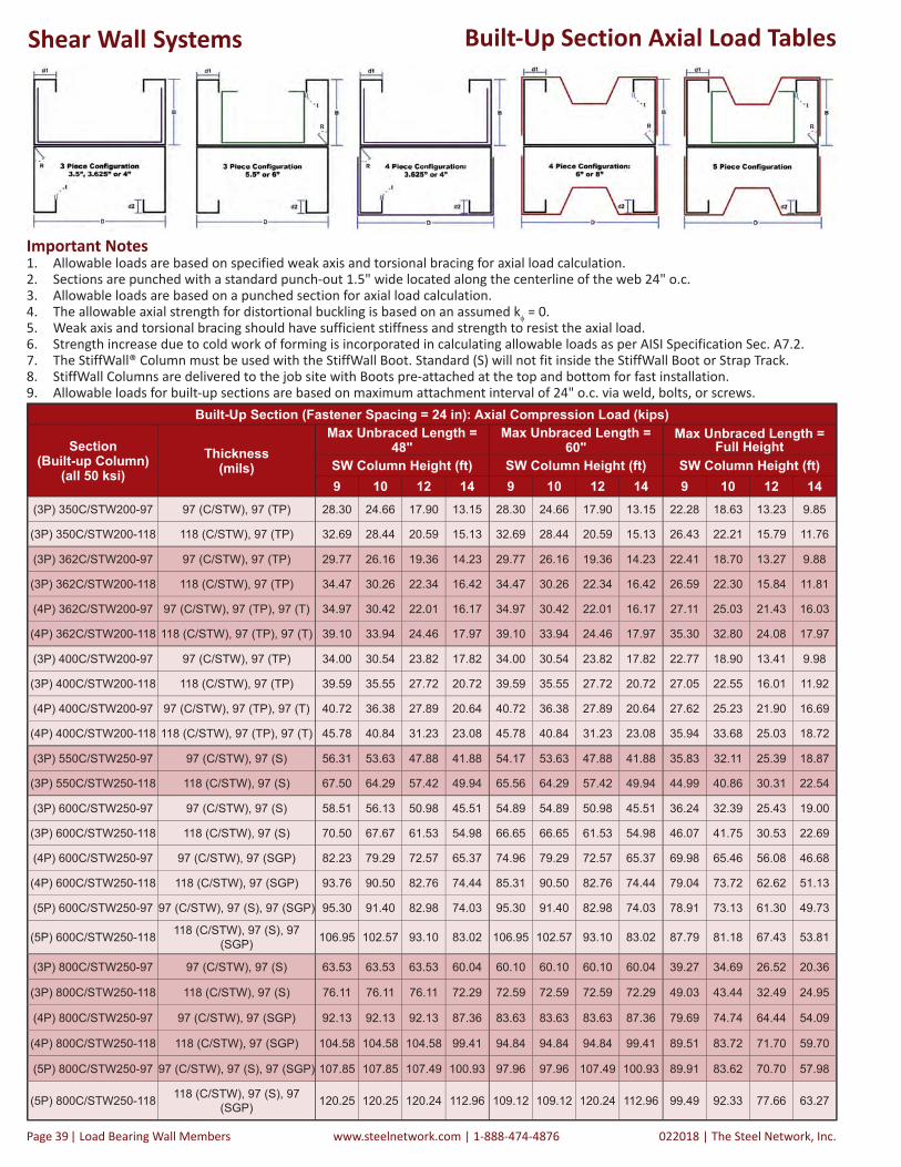
022018 | The Steel Network, Inc.www.steelnetwork.com | 1-888-474-4876Page | Load Bearing Wall Members 39
Important Notes1. Allowable loads are based on specified weak axis and torsional bracing for axial load calculation.2. Sections are punched with a standard punch-out 1.5" wide located along the centerline of the web 24" o.c.3. Allowable loads are based on a punched section for axial load calculation.4. The allowable axial strength for distortional buckling is based on an assumed k = 0.5. Weak axis and torsional bracing should have sufficient stiffness and strength to resist the axial load.6. Strength increase due to cold work of forming is incorporated in calculating allowable loads as per AISI Specification Sec. A7.2.7. The StiffWall® Column must be used with the StiffWall Boot. Standard (S) will not fit inside the StiffWall Boot or Strap Track.8. StiffWall Columns are delivered to the job site with Boots pre-attached at the top and bottom for fast installation.9. Allowable loads for built-up sections are based on maximum attachment interval of 24" o.c. via weld, bolts, or screws.
Built-Up Section Axial Load Tables
Built-Up Section (Fastener Spacing = 24 in): Axial Compression Load (kips)
Section(Built-up Column)
(all 50 ksi)Thickness
(mils)
Max Unbraced Length = 48"
Max Unbraced Length = 60"
Max Unbraced Length = Full Height
SW Column Height (ft) SW Column Height (ft) SW Column Height (ft)9 10 12 14 9 10 12 14 9 10 12 14
(3P) 350C/STW200-97 97 (C/STW), 97 (TP) 28.30 24.66 17.90 13.15 28.30 24.66 17.90 13.15 22.28 18.63 13.23 9.85
(3P) 350C/STW200-118 118 (C/STW), 97 (TP) 32.69 28.44 20.59 15.13 32.69 28.44 20.59 15.13 26.43 22.21 15.79 11.76
(3P) 362C/STW200-97 97 (C/STW), 97 (TP) 29.77 26.16 19.36 14.23 29.77 26.16 19.36 14.23 22.41 18.70 13.27 9.88
(3P) 362C/STW200-118 118 (C/STW), 97 (TP) 34.47 30.26 22.34 16.42 34.47 30.26 22.34 16.42 26.59 22.30 15.84 11.81
(4P) 362C/STW200-97 97 (C/STW), 97 (TP), 97 (T) 34.97 30.42 22.01 16.17 34.97 30.42 22.01 16.17 27.11 25.03 21.43 16.03
(4P) 362C/STW200-118 118 (C/STW), 97 (TP), 97 (T) 39.10 33.94 24.46 17.97 39.10 33.94 24.46 17.97 35.30 32.80 24.08 17.97
(3P) 400C/STW200-97 97 (C/STW), 97 (TP) 34.00 30.54 23.82 17.82 34.00 30.54 23.82 17.82 22.77 18.90 13.41 9.98
(3P) 400C/STW200-118 118 (C/STW), 97 (TP) 39.59 35.55 27.72 20.72 39.59 35.55 27.72 20.72 27.05 22.55 16.01 11.92
(4P) 400C/STW200-97 97 (C/STW), 97 (TP), 97 (T) 40.72 36.38 27.89 20.64 40.72 36.38 27.89 20.64 27.62 25.23 21.90 16.69
(4P) 400C/STW200-118 118 (C/STW), 97 (TP), 97 (T) 45.78 40.84 31.23 23.08 45.78 40.84 31.23 23.08 35.94 33.68 25.03 18.72
(3P) 550C/STW250-97 97 (C/STW), 97 (S) 56.31 53.63 47.88 41.88 54.17 53.63 47.88 41.88 35.83 32.11 25.39 18.87
(3P) 550C/STW250-118 118 (C/STW), 97 (S) 67.50 64.29 57.42 49.94 65.56 64.29 57.42 49.94 44.99 40.86 30.31 22.54
(3P) 600C/STW250-97 97 (C/STW), 97 (S) 58.51 56.13 50.98 45.51 54.89 54.89 50.98 45.51 36.24 32.39 25.43 19.00
(3P) 600C/STW250-118 118 (C/STW), 97 (S) 70.50 67.67 61.53 54.98 66.65 66.65 61.53 54.98 46.07 41.75 30.53 22.69
(4P) 600C/STW250-97 97 (C/STW), 97 (SGP) 82.23 79.29 72.57 65.37 74.96 79.29 72.57 65.37 69.98 65.46 56.08 46.68
(4P) 600C/STW250-118 118 (C/STW), 97 (SGP) 93.76 90.50 82.76 74.44 85.31 90.50 82.76 74.44 79.04 73.72 62.62 51.13
(5P) 600C/STW250-97 97 (C/STW), 97 (S), 97 (SGP) 95.30 91.40 82.98 74.03 95.30 91.40 82.98 74.03 78.91 73.13 61.30 49.73
(5P) 600C/STW250-118 118 (C/STW), 97 (S), 97 (SGP) 106.95 102.57 93.10 83.02 106.95 102.57 93.10 83.02 87.79 81.18 67.43 53.81
(3P) 800C/STW250-97 97 (C/STW), 97 (S) 63.53 63.53 63.53 60.04 60.10 60.10 60.10 60.04 39.27 34.69 26.52 20.36
(3P) 800C/STW250-118 118 (C/STW), 97 (S) 76.11 76.11 76.11 72.29 72.59 72.59 72.59 72.29 49.03 43.44 32.49 24.95
(4P) 800C/STW250-97 97 (C/STW), 97 (SGP) 92.13 92.13 92.13 87.36 83.63 83.63 83.63 87.36 79.69 74.74 64.44 54.09
(4P) 800C/STW250-118 118 (C/STW), 97 (SGP) 104.58 104.58 104.58 99.41 94.84 94.84 94.84 99.41 89.51 83.72 71.70 59.70
(5P) 800C/STW250-97 97 (C/STW), 97 (S), 97 (SGP) 107.85 107.85 107.49 100.93 97.96 97.96 107.49 100.93 89.91 83.62 70.70 57.98
(5P) 800C/STW250-118 118 (C/STW), 97 (S), 97 (SGP) 120.25 120.25 120.24 112.96 109.12 109.12 120.24 112.96 99.49 92.33 77.66 63.27
Shear Wall Systems

The Steel Network, Inc. | 022018 www.steelnetwork.com | 1-888-474-4876 Load Bearing Wall Members | Page 40
350-362-400 Depths1
350-362-400 Depths1
550-600-800 Depths1
550-600-800 Depths1
StiffWall® Boots
Light Boot Plus Boot
Small Boot
StiffWall® Strap Track3
Boot Dimensions And ThicknessStiffWall® Boots are designed to provide the optimal cost-effective solution for shear wall connections. Six configurations are available to meet project requirements (Light, Plus, Small, Medium, Transition and Large). StiffWall Boots are sized to fit inside standard track and are available for 3.5", 3.625", 4", 5.5", 6" and 8" Depths. During installation of StiffWall Boots, standard or plate washer shall be used with a size sufficient to cover the Boots' slots after installation. Light and Plus Boots can be used with single StiffWall column only. The Steel Network will determine the actual bearing height the StiffWall Columns, which are delivered to the job site with Boots pre-attached at the top and bottom for fast installation.
Subtract Boot Thickness to Determine Column Bearing Height The Steel Network will determine the actual bearing height of a StiffWall Column by subtracting the thickness of the StiffWall Boot and Strap Track elements on which it is bearing. For each boot, the Strap Track is 97mils thick. The dimensions of various boot elements are shown in the table below. Contact TSN for design recommendations or assistance with any light steel framing technical issue.
1 Total thickness rounded to nearest 1/32", with 1/32" added for installation tolerance.
Boot Type Strap Track Thickness Base Plate Thickness Additional Base Plate Thickness
Total Thickness of Two Boots1
Light, Plus 0.1017" 0 0.1242" 0.5"Small, Medium, Transition 0.1017" 0.5" 0 1.25"
Large 0.1017" 0.75" 0 1.75"
12"
Column Depth
3.75"
Medium Boot
Transition Boot
350-362-400 Depths1
550-600-800 Depths1
350-362-400 Depths1
550-600-800 Depths1
550-600-800 Depths (only)2
Large Boot
350-362-400 Depths1
550-600-800 Depths1
2 The StiffWall Transition Boot is used when the floor above uses a Small or Medium Boot and the floor below uses a Large Boot (for depths greater than 4" only). The anchor hole of the Transi on Boot at the base of the wall couples with that of the Large Boot at the underside of the fl oor below to maintain the con nuity of the through-fl oor fasteners (1 ¼" threaded rods or anchors).
1 Boots less than or equal to 4" and Light, Plus and Medium Boots greater than 4" contain guide holes for ⅞" anchors. Transition and Large Boots greater than 4" contain guide holes for 1 ¼" anchors.
6"
3"
3 StiffWall Strap Track is available in 12ga (97mils) thickness. Center hole is for conditions where only one anchor is necessary
Shear Wall Systems

022018 | The Steel Network, Inc.www.steelnetwork.com | 1-888-474-4876Page | Load Bearing Wall Members 41
StiffWall® BootsLoad Direction Diagram
If load capacities exceed published loads, custom boot connections
may be manufactured. Contact TSN for recommendations.
Material CompositionCold-Formed Steel: ASTM A 1003/A 1003M, ST50H or equivalent (Min. Fy = 50 ksi, Min. Fu = 65 ksi).Structural Steel: ASTM A 572/A 572M, Grade 50 or equivalent (Min. Fy = 50 ksi, Min. Fu = 65 ksi). Coating Powder – Black or TSN approved equivalent.Bolts: ASTM F3125 Grade A325.Important Notes1. Allowable loads are based on analysis of loads and allowable stresses set by AISI S100 and
AISC 360 Spec.2. Straps tension T1 is the summation of tension forces in the the two diagonal straps.3. Load paths for straps tension and column uplift are independent in the boot connection and
allowable loads T1 and T2 can be combined for the same boot. 4. Check combined tension and shear in anchor bolts due to applied T1 and T2 values as per
AISC 360 Specification, Sec. J3.7.5. Allowable loads for wall aspect ratio other than listed can be interpolated, but not extrapolated.6. Fillet Weld Designation is E70XX Metal Arc or equivalent. Thickness as specified.7. For seismic design with coefficient R > 3, consider connection special seismic requirements
in AISI S213.StiffWall® Boot Capacity (kips)
Wall Light Plus Small / Medium / Transition Large
Width (in)
Aspect Ratio Straps Tension
Column Uplift
Straps Tension
Column Uplift
Straps Tension
Column Uplift
Straps Tension
Column Uplift
Vertical: Horizontal T1 T2 T1 T2 T1 T2 T1 T2
3.5
0.6:1 (30.96 deg.) 12.00 1.78 12.75 4.79 18.60 8.65 18.60 19.46
1:1 (45 deg.) 8.73 1.78 15.47 4.79 22.08 8.65 22.08 19.46
2:1 (63.5 deg.) 6.91 1.78 12.38 4.79 26.81 8.65 29.01 19.46
3.625
0.6:1 (30.96 deg.) 11.59 1.83 12.75 4.98 18.60 8.98 18.60 20.21
1:1 (45 deg.) 8.43 1.83 15.12 4.98 22.08 8.98 22.08 20.21
2:1 (63.5 deg.) 6.67 1.83 11.95 4.98 25.88 8.98 29.01 20.21
4
0.6:1 (30.96 deg.) 10.50 1.97 12.75 5.56 18.60 9.98 18.60 22.46
1:1 (45 deg.) 7.64 1.97 13.70 5.56 22.08 9.98 22.08 22.46
2:1 (63.5 deg.) 6.04 1.97 10.83 5.56 23.46 9.98 29.01 22.46
5.5
0.6:1 (30.96 deg.) 7.64 2.49 12.75 7.86 18.60 13.98 21.48 35.76
1:1 (45 deg.) 5.56 2.49 9.96 7.86 21.58 13.98 25.34 35.76
2:1 (63.5 deg.) 4.39 2.49 7.88 7.86 17.06 13.98 32.23 35.76
6
0.6:1 (30.96 deg.) 7.00 2.65 12.55 8.62 18.60 15.32 21.48 39.16
1:1 (45 deg.) 5.10 2.65 9.13 8.62 19.78 15.32 25.34 39.16
2:1 (63.5 deg.) 4.03 2.65 7.22 8.62 15.64 15.32 32.23 39.16
8
0.6:1 (30.96 deg.) 5.25 3.21 9.41 11.69 18.60 20.65 21.48 52.80
1:1 (45 deg.) 3.82 3.21 6.85 11.69 14.84 20.65 25.34 52.80
2:1 (63.5 deg.) 3.02 3.21 5.42 11.69 11.73 20.65 25.81 52.80
Boot ComponentsS ff Wall Boots come pre-assembled with S ff Wall Columns. Please refer to the S ff Wall product page for full system design and order informa on. Contact TSN technical support for design recommenda ons.
S ff Wall Base PlateStrap Track
A325 Column Bolts
Please Note: Boot Kits may NOT be sold separately, as they are part of an engineered system.
Shear Wall Systems

The Steel Network, Inc. | 022018 www.steelnetwork.com | 1-888-474-4876 Load Bearing Wall Members | Page 42
StiffWall® SWS Example Problem
Maximum Compression Check
Sample StructureThe following example is used to illustrate the design capabilities of The Steel Network’s StiffWall® SWS system as a shear panel to resist lateral loads. The information contained within this catalog shows the step by step design process used to design TSN’s StiffWall.
Certain assumptions are made within the catalog and the example problem. All analyses are shown for example only and do not replace building code specific loading requirements and/or load combinations. Please contact The Steel Network for further information.
The example utilizes StiffWall in the construction of a 5-story building structure. Loads and reactions at each story have been provided as well as overall foundation reactions for anchorage design. Service wind loads and ASD design method are used. Two load cases were examined: (1) Dead + In-plane Wind, (D + W) (2) Dead + 0.75 Live + 0.75 In-plane, (D + 0.75L + 0.75W)
Uplift CheckAssumptions - Stud Spacing = 24 inch o.c.- Dead Load = 0.5 kips/ft.- Live Load = 0.75 kips/ft.- Tributary Width = 2.0 ft. for Compression check; 5 ft. for Uplift check- D + W load combination checked- D + 0.75L + 0.75W load combination checked
Important Design Considerations:• D + W load combination is the controlling combination in this example. The wall depth is chosen as 6 inches.• Uplift and tension loads in StiffWall columns are calculated with a tributary width from the dead load = 5 ft. (about ⅓ of panel
width). Compression loads in StiffWall columns are calculated with a tributary width from dead load equal to stud spacing = 2 ft.• End columns are designed as unbraced full height in the lateral and torsional directions under compression forces. Otherwise, if
bracing is considered, it must be adequately designed for bracing force. See bridging data for details of lateral bracing calculations.• Back-to-back end columns are designed to be attached together at 24 inch max. o.c.• StiffWall does not substitute for floor rigidity. Sufficient diaphragm stiffness or an additional horizontal compression member is
required to transfer the load.• Floor summaries on the next page refer to the design steps previously given (pages titled StiffWall® SWS Design). Step 5 is
designed by others.• f’c of foundation concrete = 4,000 psi.
Shear Wall Systems

022018 | The Steel Network, Inc.www.steelnetwork.com | 1-888-474-4876Page | Load Bearing Wall Members 43
StiffWall® SWS Example Problem
Uplift Check Max. CompressionCheck
Loads on Top Floor Shear Wall From Analysis: 1. Column compression = 3.1 kips. No tension in column • Use 600C/STW250-54 with allowable capacity = 3.5 kips > 3.1 kips
2. Use StiffWall Light Boot with T1 capacity of 6.5 3. Attach StiffWall Light Boot to column using (4) #12 screws 4. The tension in the flat strap is: 3.7 kips in 2 straps: • Use (2) 4” x 54mil straps with capacity = 11.5 kips > 3.7 kips • Use (6) #12 screws each strap each Strap Track with capacity = 6.8 kips > 3.7 kips
5. No uplift in through-floor connection, shear = 3.0 kips • Use One ⅞” A325 bolt through floorLoads on 4th Floor Shear Wall From Analysis: 1. Column compression = 8.4 kips. No tension in column • Use 600C/STW250-118 with allowable capacity = 10.7 kips > 8.4 kips
2. Use StiffWall® Plus Boot with T1 capacity = 11.6 kips 3. Attach StiffWall® Plus Boot to column using (4) #12 screws 4. The tension in the flat straps is: 7.4 kips in 2 straps: • Use (2) 4” x 54 mil straps with capacity =11.5 kips > 7.4 kips • Use (7) #12 screws each strap to Strap Track with capacity = 8.0 kips > 7.4 kips
5. Uplift in through-floor connection = 1.4 kips, shear = 6.0 kips • Use One ⅞” A325 bolt through floor • Use (2) ⅞” A325 bolts at base to connect to Small Boot belowLoads on 3rd Floor Shear Wall From Analysis: 1. Column compression = 15.8 kips. No tension in column • Use (2) 600C/STW250-97 with allowable capacity = 25.5 kips > 15.8 kips
2. Use StiffWall Small Boot with T1 capacity = 18.9 kips 3. Attach StiffWall Small Boot to column using (4) ½” A325 bolts 4. The tension in the flat straps is: 11.1 kips in 2 straps: • Use (2) 4” x 54 mil straps with capacity = 11.5 kips > 11.1 kips • Use (10) #12 screws each strap to Strap Track with capacity = 11.4 kips > 11.1 kips
5. Uplift in through-floor connection = 5.3 kips, shear = 9.0 kips • Use (2) ⅞” A325 bolt through floorLoads on 2nd Floor Shear Wall From Analysis: 1. Column compression = 24.7 kips. • Use (2) 600C/STW250-97 with allowable capacity = 25.5 kips > 24.7 kips
2. Column tension = 2.8 kips* • Use StiffWall Small Boot with T1 capacity = 18.9 kips & T2 capacity = 15.3 kips
3. Attach StiffWall Small Boot to column using (4) ½” A325 bolts • Capacity of (4) ½” A325 bolts to (2) 97 mil columns = 21.2 kips > 2.8 kips
4. The tension in the flat straps is: 13.5 kips in 2 straps: • Use (2) 6” x 54 mil straps with capacity = 17.3 kips > 13.5 kips • Use (12) #12 screws each strap to Strap Track with capacity = 13.7 kips > 13.5 kips
5. Uplift in through-floor connection = 10.7 kips, shear = 11.0 kips • Use (2) ⅞” A325 bolt through floor
* Uplift calculated using 5 ft. tributary width and dead load used to offset uplift at the tension side of the wall.Loads on 1st Floor Shear Wall Loads From Analysis: 1. Column compression = 35.0 kips • Use (2) 600C/STW250-118 with allowable capacity = 34.7 kips ≈ 35.0 kips
2. Column tension = 8.2 kips* • Use StiffWall Small Boot with T1 capacity = 18.9 kips & T2 capacity = 15.3 kips
3. Attach StiffWall® Small Boot to column using (4) ½” A325 bolts • Capacity of (4) ½” A325 bolts to (2) 118 mil columns = 21.2 kips > 8.2 kips
4. The tension in the flat straps is: 16.0 kips in 2 straps: • Use (2) 6” x 54 mil straps with capacity = 17.3 kips > 16.0 kips • Use (15) #12 screws each strap to Strap Track with capacity = 17.1 kips > 16.0 kips
* Uplift calculated using 5’ tributary width and dead load used to offset uplift at the tension side of the wall.
5. Anchorage uplift = 17.5 kips, shear = 13.0 kips • Use (2) ⅞” Hilti HIT-HY 200 Adhesive Anchors, HAS Super ASTM A193 B7, Embedment depth = 10.5 inches; check additional tension from prying action.
Shear Wall Systems

The Steel Network, Inc. | 022018 www.steelnetwork.com | 1-888-474-4876 Load Bearing Wall Members | Page 44
StiffWall® SWS Example Problem
Typical Detail, StiffWall® SWS Back-to-Back Column at SW-2 Above
StiffWall® SWS Schedule
Wall # StiffWall® Column & Boot Section
Strap Bracing(50ksi)
Column Connection to Boot
Strap Track #12 Screws (Each Side) Floor/Anchorage Connection
SW-5 600C/STW250-54-1-LT (2) 4" x 54 mil (4) #12 Screws 6 (1) ⅞" Bolt
SW-4 600C/STW250-118-1-PL (2) 4" x 54 mil (4) #12 Screws 7 (1) ⅞" Bolt, (2) at base
SW-3 600C/STW250-97-2-SM (2) 4" x 54 mil (4) ½” A325 Bolts 10 (2) ⅞" Bolt
SW-2 600C/STW250-97-2-SM (2) 6" x 54 mil (4) ½” A325 Bolts 12 (2) ⅞" Bolt
SW-1 600C/STW250-118-2-SM (2) 6" x 54 mil (4) ½” A325 Bolts 15 (2) ⅞” Hilti HIT-HY 200 Adhesive Anchors
Shear Wall Systems

022018 | The Steel Network, Inc.www.steelnetwork.com | 1-888-474-4876Page | Load Bearing Wall Members 45
Flat Strap
Flat Strap Product Profile (For StiffWall®)
SectionWidth (D)
GaugeDesign Thickness (t) Min. Steel Thickness (t(min)) Area Weight
(in) (in) (in) (in2) lbs/ftFS400-54, 50 ksi 4 16 0.0566 0.0538 0.226 0.770
FS600-54, 50 ksi 6 16 0.0566 0.0538 0.340 1.156
FS800-54, 50 ksi 8 16 0.0566 0.0538 0.453 1.541
FS800-68, 50 ksi 8 14 0.0713 0.0677 0.570 1.941
FS1000-68, 50 ksi 10 14 0.0713 0.0677 0.713 2.426
Flat Strap Product Profile (For Bridging)FS200-43, 50 ksi 2 18 0.0451 0.0428 0.090 0.307
FS300-43, 50 ksi 3 18 0.0451 0.0428 0.135 0.460
FS300-54, 50 ksi 3 16 0.0566 0.0538 0.170 0.578
Material PropertiesA1003 / A1003M ST50H [ST340H], Grade 50 (340), 50ksi (340MPa) minimum yield strength, 65ksi (450 MPa) minimum tensile strength, G-60 (Z180) hot-dipped galvanized coating; or equivalent.
Table Notes:· Section properties and capacities are calculated in accordance with AISI S100.· Structural framing is produced to meet or exceed ASTM C955, A653, and A1003.· Non-Structural framing is produced to meet or exceed ASTM C645, A653, and A1003.· Galvanized sheet steel meets or exceeds requirements of ASTM A924 & A1003.
Order Informa on for S ff Wall Flat StrapThe Selec on of fl at strap for S ff Wall® is simplifi ed to 6 strap types, with load capacity factored using standard 12ga (97mil) strap track (see Step-By-Step Design Procedure on TSN’s S ff Wall product page for Allowable Flat Strap Capacity Chart). Flat Strap is cut to length with square ends, and will need to be cut to fi nal length in the fi eld. To determine the length of the fl at straps, follow these simple steps:
1. Find the width (A) and the height (B) of the S ff Wall. 2. Then, use the following formula to determine the length of the strap: A2 + B2 = C2 3. Next, take the square root of C, round up to the nearest whole number and add 1
This will result in a length in feet that you can work with. If C equals a whole number, you may want to add 2 to make sure the length is enough.
Example: 8’ wall height with a width of 16’ would look like this: (8x8) + (16x16) = √320. = 17.88 Round up to 18’ and add 1’ for a strap length of 19’.
Some points to remember concerning Flat Strap:- Strap must be pulled ght a er a gravity load above has been applied. TightStrap® tool can be used to fl a en the strap and put minor tension force into it.- Flat strap cannot be installed, then un-installed by releasing the screws to the strap track, and then re-installed with screws again in the same screw holes. Either a new piece of strap is required, or the exposed edge of the strap needs to be welded to the strap track with an approved weld design. - It is recommended not to fasten the strap to the infi ll studs between the columns. However, typical or occasional a achment of sheathing and/or resilient channel to the infi ll studs through the strap is acceptable.- Straps should not be spliced without an approved design.- Four (4) pieces of strap are required in each S ff Wall (If there are 10 S ff Wall shear walls, 40 pieces of fl at strap will be necessary).
Shear Wall Systems

The Steel Network, Inc. | 022018 www.steelnetwork.com | 1-888-474-4876 Load Bearing Wall Members | Page 46
Product DescriptionThe pre-tensioning of a shear wall flat strap provides a means to ensure the shear wall will perform as designed. It is important that the flat straps are as tight as possible when installed to achieve optimal system performance.
TightStrap® is a unique device used to tension (tighten) flat strap in the field. Use TightStrap to improve structural performance of a shear wall by removing “waviness” or “bowing” prior to fastening.
TightStrap is designed to be used in both StiffWall® and generic flat strap shear walls. TightStrap’s track connector fastens to standard track at the corners of the shear wall to provide a base for the tensioning process. It is preferable to tighten the flat straps after applying some vertical load (own weight) on top of the shear wall panel. View the animated installation procedure at www.steelnetwork.com.
Using TightStrap®
Tightstrap® Strap Tensioner
Step 1 - Align & trim flat strap at each corner, attach one end with at least 2
screws.
Step 2 - Align Track Connector and attach to track.
Step 3 - Extend Bar Clamp, align Strap Connector with centerline of flat strap and
attach Strap Connector to the flat strap.
Step 4 - Engage Bar Clamp, install at least 2 screws for flat strap attachment, remove TightStrap and install remaining screws for strap attachment.
Patent Pending
How to Install the S ff Wall® Shear Wall:The boots are a ached to the founda on or fl oor and the roof or ceiling with approved anchors or bolts as determined and approved by the Engineer (Boots are made up of the Strap Track and the “T” shaped Base Plate)• Light, Plus, Small & Medium Boots u lize a ⅞” anchor bolt or threaded rod.• Transi on and Large Boots u lize a ⅞” anchor bolt or threaded rod on boots less than or equal to 4". Boots greater 4" contain guide
holes for 1 ¼” anchor bolt or threaded rod.• A ach the Flat Strap to the Strap Track, corner to corner, on both sides (4 straps needed) with the specifi ed amount of #12 screws
(or weld). The use of low profi le screws help to reduce a “bump out” of fi nished sheetrock. To achieve the designed loads, the strap should be ght from corner to corner (with no slack). This is done by ghtening the strap a er the wall is loaded with a TightStrap®
tool.
Shear Wall Systems

022018 | The Steel Network, Inc.www.steelnetwork.com | 1-888-474-4876Page | Load Bearing Wall Members 47
Other Design ConsiderationsS ff Wall® Placement in Load Bearing WallS ff Wall is usually not designed as a gravity load bearing element. However, its boundary end columns can see compression loads from the fl oor weight above. This system is designed to sit in between load bearing studs and address all of the lateral loads ac ng on that building due to wind or earthquakes.
The S ff Wall is designed to stack ver cally and a ach through the fl oor system to the level above (Fig. 1). The Columns for one fl oor must line up with the columns on the fl oors above and below. This will allow for the bolts from one fl oor to be bolted through the fl oor system to the boots above and/or below. It is important that these bolts are properly aligned through each fl oor for the walls to be able to work together as one unit from top to bo om. Do not enlarge the anchor holes in the S ff Wall® Boots.
It is recommended that StiffWall boundary end columns have axial compression capacity greater than or equal to the typical load bearing stud within the wall.
Fig. 1: StiffWall Column/Boot Assembly (blue line) is placed within the spacing of the SigmaStud® (in red).
Attachment of Sheathing to the StiffWall® ColumnSince the StiffWall assembly is installed within the thickness of the top and bottom tracks, sheathing should not be attached directly to the StiffWall Column. The thickness of the strap track on either side of the wall (97mils [12ga]) reduces the depth of the StiffWall Column within the assembly (Fig. 2). As a result, if the sheathing is attached to the StiffWall Column, a level plane will not occur along the wall. Attach the sheathing to the infill studs bordering the StiffWall columns.
Fig. 2: Sheathing should not be attached directly to the StiffWall Column. Attach
the sheathing to the adjacent studs.
Vertically Stacking Shear Walls StiffWall shear walls transfer loads concentrically from the floor element above to the floor element below. The StiffWall system should consist of vertically stacked panels to effectively transfer lateral forces to the foundation (Fig. 3). Any eccentricity in the system negatively effects the load distribution to the StiffWall components. The vertical alignment of the walls is critical for the through-floor connections. Coordinate installation to ensure through-floor connectors align with StiffWall Boots on the floors above and below.
Fig. 3: Shear walls should be stacked vertically.
Shear Wall Systems
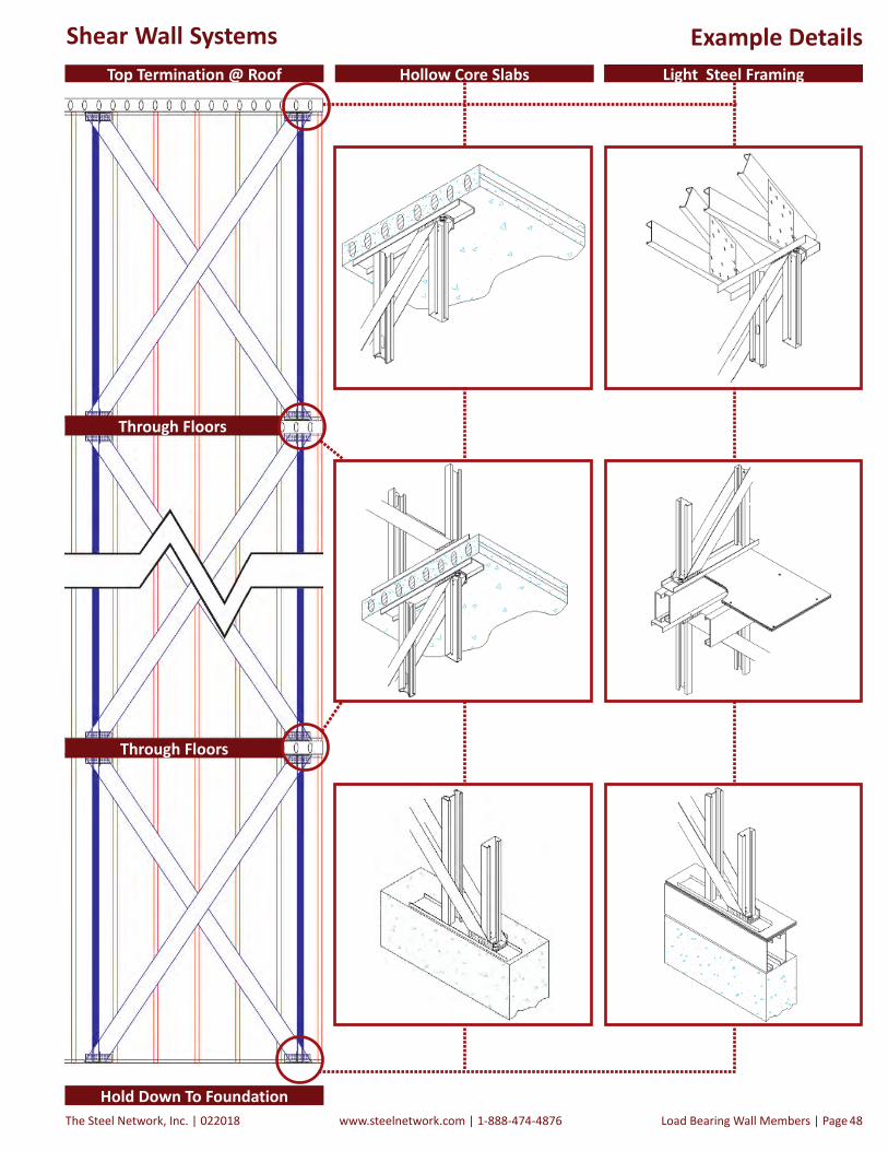
The Steel Network, Inc. | 022018 www.steelnetwork.com | 1-888-474-4876 Load Bearing Wall Members | Page 48
Example DetailsHollow Core Slabs Light Steel FramingTop Termination @ Roof
Through Floors
Through Floors
Hold Down To Foundation
Shear Wall Systems

022018 | The Steel Network, Inc.www.steelnetwork.com | 1-888-474-4876Page | Load Bearing Wall Members 49
IntroductionFloor SystemsFloor Systems Appropriate for Cold-Formed Steel Load Bearing ConstructionSeveral types of floor systems can be integrated with cold-formed steel stud load bearing walls. Among these floor systems are the composite steel deck-concrete slab, composite bar joist with concrete on metal deck or structural panel floor diaphragm, hollow core concrete planks or cold-formed steel joist with concrete on metal deck or structural panel floor diaphragm. This section provides a short introduction to these floor systems.
Composite steel deck-concrete slabs combine the structural advantage of a flat slab with the time saving advantage of a permanent form. The steel deck furnishes the total bottom reinforcement of the composite slab, while additional top reinforcement is required. Due to the composite action between the concrete and the steel deck, the slab can support a greater floor live load than a typical reinforced concrete slab of the same depth. The steel deck is typically spot-welded to the top track of the wall panel.Composite bar joist with concrete on metal deck or structural panel floor diaphragm enables clear spans for 10 to 24 inch deep system. The metal deck provides permanent form and tension reinforcement, and the concrete slab thickness is typically about 2½” on top of deck. This system necessitates in-line framing between the joists and the wall studs to ensure transfer of gravity loads to the wall studs without eccentricity.
Precast hollow core concrete slabs provide the advantages of rapid field installation. The planks are typically produced in 6, 8, 10, 12, and 16 inch depths. The hollow core floor system provides long design spans compared to other systems meeting the requirements of cold-formed steel load bearing construction. However, factors such as concentrated loads and large openings can affect the span capabilities of the system. Sound Transmission Class (STC) rating and fire resistance rating typically meet the most stringent design criteria.
Cold-formed steel joist with concrete on metal deck or structural panel floor diaphragm is a non-composite system that is significantly lighter than all other floor systems. The joists are typically 8 to 16 inches deep. Relatively sizeable cold-formed steel joists (97 mils thick. and 14 inches deep) can accommodate clear spans up to 30 ft. Cold-formed steel joists require lateral bracing, or blocking, to prevent lateral torsional buckling, and may require end and intermediate bearing stiffeners to prevent web crippling.
Pre-Cast Hollow Core SlabComposite Steel Deck
Cold-Formed Steel JoistComposite Bar Joist

The Steel Network, Inc. | 022018 www.steelnetwork.com | 1-888-474-4876 Load Bearing Wall Members | Page 50
PrimeJoist® IntroductionFloor Systems
BackgroundPrimeJoist is a revolutionary addition to the light gauge steel stud industry, producing significant economies in both design and installation when compared with conventional “C” Shaped studs. PrimeJoist’s unique configuration delivers increased strength and stiffness, minimizing or eliminating the use of built-up joist sections in floor assemblies. Available in all common floor joist depths, PrimeJoist streamlines the design and construction process. PrimeJoist’s shape is easily differentiated from the typical c-shape, enabling the selection of the most optimal member sizes to fit project conditions.ASI’s SteelSmart® System software includes the complete database of sections to quickly design PrimeJoist floor joists and connections. Visit www.steelsmartsystem.com for your copy today!
Benefits That Add Value:Quality• Increases load capacity over a standard “C-shaped” stud of
the same thickness, reducing overall materials needed • Increased s ff ness for defl ec on• Increased load capacity enables selec on of op mal
thickness of fl ooring membersValue• Simplifi ed joist and fl oor system design• Lighter weight results in shipping effi ciencies and easier
handling• Provides a fl at surface for a achment of door or window
frame, requiring no addi onal track• No welding or fastening built-up members togetherPrimeJoist®

022018 | The Steel Network, Inc.www.steelnetwork.com | 1-888-474-4876Page | Load Bearing Wall Members 51
UL G549
UL G557
UL G565
UL L568
Fire Resistance Rating: 1hr
Fire Resistance Rating: 2hr
Fire Resistance Rating: 1 hr, 1 ½ hr, 2 hr
Fire Resistance Rating: 45 min
Fire & Sound Tested Assemblies
• 1 ⅜” concrete• 28 ga (0.015” thick) steel deck with ⅝” deep corruga ons• 8” x 18 MSG steel joist spaced at 16” o.c. or 24” o.c. • Op onal resilient metal channels spaced at 24” o.c.• Op onal 3 ½” mineral wool or glass fi ber ba insula on• 2 layers of ½” gypsum board on ceiling side
• Subfl oor of ¾” thick tongue-and-grove cement-fi ber board designated “Fortacrete”
• 10” x 16 MSG, 6” x 18 MSG or 8” x 16 MSG steel joist spaced at 24” o.c.
• 3 ⅝” glass fi ber ba insula on• Resilient metal channels spaced at 12” o.c.• 2 layers of ⅝” gypsum board on ceiling side.
• 1” min. fl oor topping mixture with 3,500 psi comp. strength• 9⁄16” min. deep, 22 MSG corrugated fl uted steel deck• 9 ¼” x 16 MSG steel joist spaced at 24” o.c.• 3 ½” mineral wool or glass fi ber insula on• 1 and ½ hour – 1 layer of ⅝” gypsum board on ceiling side• 2 hour – 2 layers of ⅝” gypsum board on ceiling side
• Subfl oor of ⅝” plywood and fi nish fl oor of ⅝” wood structural panels
• 8” x 18 MSG steel joists spaced at 16” o.c.• Resilient metal channels spaced 16” o.c.• 3 ½” mineral wool ba insula on• 1 layer of ⅝” gypsum board on ceiling side
Introduc onFire-resistance ra ngs have long been used by UL and the building codes to measure the performance of building components or assemblies in a fi re situa on. Fire-resistance ra ng of a fl oor system classifi es the ability of the fl oor assembly to confi ne and isolate fi re within a zone comprised of the assembly. The ra ngs are obtained from fi re tests designed to determine the me it takes for a fi re to raise the temperature to unacceptable levels. Building codes require fi re resistance ra ngs that are based on laboratory tes ng done in accordance with ASTM E119: Standard Test Methods for Fire Tests of Building Construc on and Materials.Sound Transmission Class (STC) of a fl oor system measures the ability of the fl oor assembly to block airborne sound transmission. STC is reported as a numerical value, and higher values represent a be er ability to block airborne sounds. STC can be measured through a laboratory test which is based on ASTM E90, or a fi eld test that is based on ASTM E413.Impact Insula on Class (IIC) of a fl oor system measures the ability of the fl oor assembly to block impact sound transmi ed through the assembly and structure. Impact sound transmission arises from a variety of sources, most notably the movement of people within a building. Like STC values, IIC also is reported as a numerical value, and higher values represent less sound transmission. The procedure for the IIC test is defi ned in ASTM E492 and E989.Fire-resistance rated fl oor assemblies are iden fi ed in the UL Fire Resistance Directory, and can be found at the Underwriters Laboratories website at ul.com. Data for STC and IIC can be found for some assemblies through specifi c publica ons such as “A Guide to Fire and Acous c Data for Cold-Formed Steel Floor, Wall & Roof Assemblies” by the Steel Framing Alliance. This sec on presents sample rated fl oor assemblies from this publica on.
Sound Transmission Class Impact Insulation Class24" Joist Spacing
65* (GFB RC)60* (NI RC)
29* (GFB RC)30* (NI RC)
16" Joist Spacing66a (GFB RC)60* (NI RC)
34b (GFB RC)<30* (NI RC)
Sound Transmission Class Impact Insulation Class53* 46*
a TLF-02-051a b IIF-02-032* Es mated value per Warnock (2008)
* Es mated value per Warnock (2008)
Floor Systems
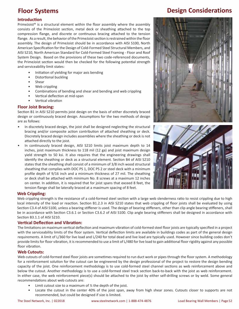
The Steel Network, Inc. | 022018 www.steelnetwork.com | 1-888-474-4876 Load Bearing Wall Members | Page 52
Design ConsiderationsIntroduc onPrimeJoist® is a structural element within the fl oor assembly where the assembly consists of the PrimeJoist sec on, metal deck or sheathing a ached to the top compression fl ange, and discrete or con nuous bracing a ached to the tension fl ange. As a result, the behavior of the PrimeJoist sec on is restrained within the fl oor assembly. The design of PrimeJoist should be in accordance with AISI S100, North American Specifi ca on for the Design of Cold-Formed Steel Structural Members, and AISI S210, North American Standard for Cold-Formed Steel Framing - Floor and Roof System Design. Based on the provisions of these two code-referenced documents, the PrimeJoist sec on would then be checked for the following poten al strength and serviceability limit states:
• Ini a on of yielding for major axis bending• Distor onal buckling• Shear• Web crippling• Combina ons of bending and shear and bending and web crippling• Ver cal defl ec on at mid-span• Ver cal vibra on
Floor Joist Bracing:Sec on B1 in AISI S210 permits joist design on the basis of either discretely braced design or con nuously braced design. Assump ons for the two methods of design are as follows:• In discretely braced design, the joist shall be designed neglec ng the structural
bracing and/or composite ac on contribu on of a ached sheathing or deck. Discretely braced design includes assemblies where the sheathing or deck is not a ached directly to the joist.
• In con nuously braced design, AISI S210 limits joist maximum depth to 14 inches, joist maximum thickness to 118 mil (12 ga) and joist maximum design yield strength to 50 ksi. It also requires that the engineering drawings shall iden fy the sheathing or deck as a structural element. Sec on B4 of AISI S210 states that the sheathing shall consist of a minimum of 3/8 inch wood structural sheathing that complies with DOC PS 1, DOC PS 2 or steel deck with a minimum profi le depth of 9/16 inch and a minimum thickness of 27 mil. The sheathing or deck shall be a ached with minimum No. 8 screws at a maximum 12 inches on center. In addi on, it is required that for joist spans that exceed 8 feet, the tension fl ange shall be laterally braced at a maximum spacing of 8 feet.
Web Crippling:Web crippling strength is the resistance of a cold-formed steel sec on with a large web slenderness ra o to resist crippling due to high local intensity of the load or reac on. Sec on B1.2.3 in AISI S210 states that web crippling of fl oor joists shall be evaluated by using Sec on C3.4 of AISI S100, unless a bearing s ff ener is used. The design of bearing s ff eners, other than clip angle bearing s ff eners, shall be in accordance with Sec on C3.6.1 or Sec on C3.6.2 of AISI S100. Clip angle bearing s ff eners shall be designed in accordance with Sec on B3.1.1 of AISI S210.Ver cal Defl ec on and Vibra on:The limita ons on maximum ver cal defl ec on and maximum vibra on of cold-formed steel fl oor joists are typically specifi ed in a project with the serviceability limits of the fl oor system. Ver cal defl ec on limits are available in buildings codes as part of the general design requirements. A limit of L/360 for live load and L/240 for total dead and live load are typically used. However since building codes don’t provide limits for fl oor vibra on, it is recommended to use a limit of L/480 for live load to gain addi onal fl oor rigidity against any possible fl oor vibra on.Web Cutouts:Web cutouts of cold-formed steel fl oor joists are some mes required to run duct work or pipes through the fl oor system. A methodology for a reinforcement solu on for the cutout can be engineered by the design professional of the project to restore the design bending capacity of the joist. One reinforcement methodology is to use cold-formed steel channel sec ons as web reinforcement above and below the cutout. Another methodology is to use a cold-formed steel track sec on back-to-back with the joist as web reinforcement. In either case, the web reinforcement piece(s) should be a ached to the joist by either self-drilling screws or by weld. Some general recommenda ons about web cutouts are:
• Limit cutout size to a maximum of ½ the depth of the joist.• Locate the cutout in the center 40% of the joist span, away from high shear zones. Cutouts closer to supports are not
recommended, but could be designed if size is limited.
Floor Systems

022018 | The Steel Network, Inc.www.steelnetwork.com | 1-888-474-4876Page | Load Bearing Wall Members 53
PrimeJoist® Product Profile
PrimeJoist® Section Dimensions
Section(All Studs 50ksi)
Overall Depth Flange Width Return Lip 1 Return Lip 2 Inside Bend Radius Design Thickness Unit WeightD B d1 d2 R t
(lbs/ft)(in) (in) (in) (in) (in) (in)
600PJ250-33 6 2.5 0.589 0.5 0.105 0.0346 1.49600PJ250-43 6 2.5 0.610 0.5 0.105 0.0451 1.94600PJ250-54 6 2.5 0.633 0.5 0.105 0.0566 2.42600PJ250-68 6 2.5 0.663 0.5 0.105 0.0713 3.04600PJ250-97 6 2.5 0.723 0.5 0.105 0.1017 4.30600PJ250-118 6 2.5 0.768 0.5 0.105 0.1242 5.22600PJ350-68 6 3.5 0.663 0.5 0.105 0.0713 3.53600PJ350-97 6 3.5 0.723 0.5 0.105 0.1017 5.00600PJ350-118 6 3.5 0.768 0.5 0.105 0.1242 6.06800PJ250-43 8 2.5 0.610 0.5 0.105 0.0451 2.24800PJ250-54 8 2.5 0.633 0.5 0.105 0.0566 2.81800PJ250-68 8 2.5 0.663 0.5 0.105 0.0713 3.53800PJ250-97 8 2.5 0.723 0.5 0.105 0.1017 5.00800PJ250-118 8 2.5 0.768 0.5 0.105 0.1242 6.06800PJ350-68 8 3.5 0.663 0.5 0.105 0.0713 4.01800PJ350-97 8 3.5 0.723 0.5 0.105 0.1017 5.69800PJ350-118 8 3.5 0.768 0.5 0.105 0.1242 6.901000PJ250-43 10 2.5 0.610 0.5 0.105 0.0451 2.551000PJ250-54 10 2.5 0.633 0.5 0.105 0.0566 3.191000PJ250-68 10 2.5 0.663 0.5 0.105 0.0713 4.011000PJ250-97 10 2.5 0.723 0.5 0.105 0.1017 5.691000PJ250-118 10 2.5 0.768 0.5 0.105 0.1242 6.901000PJ350-68 10 3.5 0.663 0 .5 0.105 0.0713 4.501000PJ350-97 10 3.5 0.723 0.5 0.105 0.1017 6.381000PJ350-118 10 3.5 0.768 0.5 0.105 0.1242 7.751200PJ250-54 12 2.5 0.633 0.5 0.105 0.0566 3.581200PJ250-68 12 2.5 0.663 0.5 0.105 0.0713 4.501200PJ250-97 12 2.5 0.723 0.5 0.105 0.1017 6.381200PJ250-118 12 2.5 0.768 0.5 0.105 0.1242 7.751200PJ350-68 12 3.5 0.663 0.5 0.105 0.0713 4.981200PJ350-97 12 3.5 0.723 0.5 0.105 0.1017 7.071200PJ350-118 12 3.5 0.768 0.5 0.105 0.1242 8.591400PJ250-54 14 2.5 0.633 0.5 0.105 0.0566 3.961400PJ250-68 14 2.5 0.663 0.5 0.105 0.0713 4.981400PJ250-97 14 2.5 0.723 0.5 0.105 0.1017 7.071400PJ250-118 14 2.5 0.768 0.5 0.105 0.1242 8.591400PJ350-68 14 3.5 0.663 0.5 0.105 0.0713 5.471400PJ350-97 14 3.5 0.723 0.5 0.105 0.1017 7.761400PJ350-118 14 3.5 0.768 0.5 0.105 0.1242 9.441600PJ250-68 16 2.5 0.663 0.5 0.105 0.0713 5.471600PJ250-97 16 2.5 0.723 0.5 0.105 0.1017 7.761600PJ250-118 16 2.5 0.768 0.5 0.105 0.1242 9.44
Material PropertiesASTM A1003/A1003M or ASTM A653/A653M, Grade 50 (340), 50ksi (340MPa) minimum yield strength, 65ksi (450 MPa) minimum tensile strength, G-60 (Z180) hot-dipped galvanized coating.
X
Y
Important Notes1. Calculated properties are based on AISI S100-12, “North American
Specification for the Design of Cold-Formed Steel Structural Members.”2. Effective properties incorporate the strength increase from the cold-
work of forming as applicable per AISI A7.2.3. Tabulated gross properties are based on the full-unreduced cross section
of the studs, away from punchouts.4. Allowable moment is the lesser of Mal and Mad. Stud distortional buckling
is based on an assumed k = 0.5. For deflection calculations, use the effective moment of inertia.6. The effective moment of inertia for deflection is calculated at a stress
which results in a section modulus such that the stress times the section modulus at that stress is equal to the allowable moment. AISI S100-12 Specification Procedure I for serviceability determination has been used. Increases in the effective moment of Inertia (Ixe) may be possible at lower stress levels. Any modified values would be required to be calculated by a qualified engineer.
Floor Systems

The Steel Network, Inc. | 022018 www.steelnetwork.com | 1-888-474-4876 Load Bearing Wall Members | Page 54
PrimeJoist® Section Properties
1 Web-height-to-thickness ratio exceeds 200. Web stiffeners are required at all support points and concentric loads. Suitability of web holes must be evaluated independently.2 When web-height-to thickness ratio exceeds 260, or flange-width-to-thickness ratio exceeds 60, effective properties are not calculated (limitations in AISI Section B1). 3 Allowable moment includes cold-work of forming.
Section (All 50 ksi)
Gross Properties Eff ective Properties Torsional PropertiesLuArea Ix Sx Rx Iy Ry Ixe Sxe Mal Mad Vag Va (net) Jx103 Cw Xo m Ro ß
(in2) (in4) (in3) (in) (in4) (in) (in4) (in3) (kips-in) (kips-in) (lbs) (lbs) (in4) (in6) (in) (in) (in) (in)
600PJ250-332 0.438 2.522 0.841 2.400 0.402 0.958 0.175 3.209 -2.094 1.269 3.326 0.604 53.3
600PJ250-43 0.569 3.261 1.087 2.394 0.519 0.955 3.239 0.919 27.50 23.66 1,432 1,235 0.386 4.150 -2.088 1.266 3.317 0.604 53.3
600PJ250-54 0.712 4.058 1.353 2.387 0.644 0.951 4.058 1.174 35.14 32.38 2,843 1,942 0.760 5.163 -2.082 1.263 3.307 0.604 53.4
600PJ250-68 0.894 5.055 1.685 2.378 0.801 0.947 5.055 1.526 45.68 44.25 5,350 2,882 1.514 6.431 -2.074 1.259 3.295 0.604 53.5
600PJ250-973 1.265 7.047 2.349 2.361 1.111 0.937 7.047 2.305 77.07 76.03 10,653 3,964 4.360 8.956 -2.058 1.250 3.269 0.604 53.8
600PJ250-1183 1.533 8.447 2.816 2.348 1.327 0.930 8.447 2.816 95.91 95.91 12,905 3,888 7.855 10.726 -2.045 1.244 3.250 0.604 54.1
600PJ350-68 1.036 6.309 2.103 2.467 1.799 1.318 6.023 1.628 48.76 47.85 5,350 2,882 1.756 14.285 -3.006 1.771 4.106 0.464 71.5
600PJ350-97 1.468 8.816 2.939 2.451 2.513 1.308 8.729 2.534 75.86 77.71 10,653 3,964 5.061 20.020 -2.990 1.763 4.081 0.463 72.0
600PJ350-118 1.781 10.588 3.529 2.438 3.017 1.302 10.588 3.341 100.02 100.89 12,905 3,888 9.127 24.090 -2.978 1.757 4.063 0.463 72.5
800PJ250-43 0.659 6.378 1.595 3.110 0.572 0.931 6.368 1.225 36.66 32.25 1,060 1,060 0.447 7.513 -1.869 1.159 3.746 0.751 52.3
800PJ250-54 0.825 7.949 1.987 3.103 0.710 0.927 7.949 1.700 50.89 44.46 2,102 2,102 0.881 9.340 -1.862 1.156 3.736 0.752 52.2
800PJ250-68 1.036 9.923 2.481 3.095 0.883 0.923 9.923 2.260 67.68 61.31 4,219 3,368 1.756 11.624 -1.854 1.151 3.724 0.752 52.2
800PJ250-973 1.468 13.893 3.473 3.076 1.225 0.914 13.893 3.409 113.95 106.91 10,885 6,032 5.061 16.161 -1.838 1.142 3.698 0.753 52.2
800PJ250-1183 1.781 16.707 4.177 3.063 1.464 0.907 16.707 4.177 142.27 140.45 16,235 7,312 9.127 19.330 -1.825 1.136 3.679 0.754 52.3
800PJ350-68 1.179 12.165 3.041 3.212 1.990 1.299 11.749 2.406 72.03 65.37 4,219 3,368 1.998 25.787 -2.733 1.648 4.413 0.616 70.5
800PJ350-97 1.671 17.065 4.266 3.195 2.782 1.290 16.927 3.711 111.11 107.52 10,885 6,032 5.762 36.082 -2.717 1.640 4.388 0.617 70.7
800PJ350-118 2.029 20.553 5.138 3.183 3.341 1.283 20.553 4.870 145.82 140.85 16,235 7,312 10.398 43.367 -2.705 1.633 4.370 0.617 70.9
1000PJ250-431 0.750 10.814 2.163 3.798 0.611 0.903 10.814 1.532 45.86 40.54 842 842 0.508 12.166 -1.696 1.072 4.257 0.841 51.5
1000PJ250-54 0.939 13.490 2.698 3.791 0.760 0.900 13.490 2.106 63.06 56.25 1,668 1,668 1.002 15.121 -1.690 1.068 4.247 0.842 51.4
1000PJ250-68 1.179 16.864 3.373 3.782 0.945 0.895 16.864 3.055 91.46 78.17 3,344 3,344 1.998 18.812 -1.682 1.064 4.235 0.842 51.3
1000PJ250-973 1.671 23.674 4.735 3.764 1.312 0.886 23.674 4.649 155.43 138.05 9,766 7,190 5.762 26.138 -1.666 1.055 4.210 0.843 51.2
1000PJ250-1183 2.029 28.529 5.706 3.750 1.568 0.879 28.529 5.706 194.34 183.17 16,235 9,733 10.398 31.250 -1.653 1.048 4.192 0.844 51.1
1000PJ350-68 1.321 20.378 4.076 3.927 2.140 1.273 19.895 3.095 92.66 83.08 3,344 3,344 2.239 41.705 -2.513 1.545 4.833 0.730 69.9
1000PJ350-97 1.875 28.656 5.731 3.910 2.993 1.263 28.567 5.030 150.59 138.04 9,766 7,190 6.463 58.323 -2.497 1.536 4.808 0.730 69.9
1000PJ350-118 2.277 34.576 6.915 3.897 3.595 1.257 34.576 6.570 196.71 182.15 16,235 9,733 11.669 70.072 -2.485 1.530 4.790 0.731 69.9
1200PJ250-541 1.052 20.909 3.485 4.459 0.799 0.871 19.920 2.417 72.37 67.25 1,382 1,382 1.123 22.624 -1.550 0.995 4.800 0.896 50.6
1200PJ250-68 1.321 26.162 4.360 4.449 0.993 0.867 25.400 3.342 100.05 94.15 2,770 2,770 2.239 28.143 -1.542 0.991 4.788 0.896 50.5
1200PJ250-97 1.875 36.799 6.133 4.430 1.379 0.858 36.661 5.692 170.41 156.46 8,080 7,420 6.463 39.093 -1.526 0.981 4.764 0.897 50.3
1200PJ250-118 2.277 44.407 7.401 4.416 1.649 0.851 44.407 7.192 215.32 206.07 14,774 11,060 11.669 46.730 -1.514 0.974 4.746 0.898 50.2
1200PJ350-68 1.464 31.235 5.206 4.619 2.261 1.243 30.647 3.689 110.45 100.55 2,770 2,770 2.481 62.405 -2.330 1.456 5.320 0.808 69.3
1200PJ350-97 2.078 43.997 7.333 4.601 3.162 1.234 43.997 6.488 194.25 168.62 8,080 7,420 7.165 87.257 -2.314 1.447 5.296 0.809 69.2
1200PJ350-118 2.525 53.152 8.859 4.588 3.799 1.227 53.152 8.439 252.66 223.92 14,774 11,060 12.940 104.824 -2.301 1.440 5.278 0.810 69.1
1400PJ250-541 1.165 30.431 4.347 5.111 0.830 0.844 28.394 2.847 85.24 77.15 1,180 1,180 1.244 31.939 -1.433 0.932 5.375 0.929 49.9
1400PJ250-68 1.464 38.104 5.443 5.102 1.032 0.840 36.334 3.948 118.21 108.77 2,364 2,364 2.481 39.728 -1.425 0.928 5.363 0.929 49.7
1400PJ250-97 2.078 53.672 7.667 5.082 1.434 0.831 52.784 6.793 203.38 183.22 6,891 6,891 7.165 55.181 -1.410 0.918 5.339 0.930 49.5
1400PJ250-118 2.525 64.839 9.263 5.068 1.714 0.824 64.835 8.651 259.03 243.57 12,592 11,304 12.940 65.960 -1.398 0.912 5.321 0.931 49.3
1400PJ350-68 1.607 45.020 6.431 5.293 2.360 1.212 44.368 4.287 128.34 117.37 2,364 2,364 2.723 88.183 -2.174 1.378 5.850 0.862 68.7
1400PJ350-97 2.282 63.495 9.071 5.275 3.301 1.203 63.495 7.930 237.41 198.55 6,891 6,891 7.866 123.298 -2.158 1.369 5.825 0.863 68.5
1400PJ350-118 2.773 76.777 10.968 5.262 3.967 1.196 76.777 10.475 313.63 265.25 12,592 11,304 14.211 148.120 -2.146 1.362 5.807 0.863 68.4
1600PJ250-681 1.607 52.973 6.622 5.742 1.065 0.814 49.610 4.553 136.33 121.82 2,062 2,062 2.723 53.658 -1.326 0.873 5.949 0.950 49.0
1600PJ250-97 2.282 74.702 9.338 5.722 1.478 0.805 72.453 7.893 236.32 207.81 6,007 6,007 7.866 74.527 -1.311 0.864 5.925 0.951 48.7
1600PJ250-118 2.773 90.321 11.290 5.707 1.767 0.798 89.314 10.113 302.79 278.66 10,972 10,972 14.211 89.083 -1.300 0.857 5.908 0.952 48.4
Important Notes1. Calculated properties are based on AISI S100-12, “North American Specification for the Design of Cold-Formed Steel Structural
Members.”2. Effective properties incorporate the strength increase from the cold-work of forming as applicable per AISI A7.2.3. Tabulated gross properties are based on the full-unreduced cross section of the studs, away from punchouts.4. Allowable moment is the lesser of Mal and Mad. Stud distortional buckling is based on an assumed k = 0.5. For deflection calculations, use the effective moment of inertia.6. The effective moment of inertia for deflection is calculated at a stress which results in a section modulus such that the stress
times the section modulus at that stress is equal to the allowable moment. AISI S100-12 Specification Procedure I for serviceability determination has been used. Increases in the effective moment of Inertia (Ixe) may be possible at lower stress levels. Any modified values would be required to be calculated by a qualified engineer.
Floor Systems

022018 | The Steel Network, Inc.www.steelnetwork.com | 1-888-474-4876Page | Load Bearing Wall Members 55
Allowable Floor Joist Span TablesImportant Notes1. Spans are based on continuous support of compression flange over the full length of the joist.2. End shear and web crippling capacity have not been reduced for punchouts.3. Calculated allowable properties are based on AISI S100-12, “North American Specification for Design of Cold-Formed Steel Structural
Members.”4. For two equal spans, the listed span is the center-to-center distance from either end to the center support, with the joist continuous
over the center support.5. Joists must be braced against rotation at all supports.6. End and interior web crippling checks are based on 3.5 inch bearing length. Joist flanges must be fastened to the support.7. Shear capacity at mid-span support has been reduced for the presence of punchouts adjacent to the support. Mid-span combined
bending and shear check based on stiffened web.8. Deflection checks are computed using unbalanced loads for the two equal span condition.9. Total load defl ection limited to L/240. Live load deflection limit as noted.10. " e " indicates that web stiffeners are required at the end supports only.11. " i " indicates that web stiffeners are required at the interior supports only.12. " a " indicates that web stiffeners are required at all the supports.13. Allowable flexural strength values in the tables are based on the minimum of local, distortional, and lateral-torsional buckling.
Distortional buckling strength is based on a k = 0. Higher values may be obtained when sheathing is applied to the walls resulting in a higher k value.
10 psf Dead Load and 20 psf Live Load
Section(All Studs 50ksi)
Live Load Deflection L/360 Live Load Deflection L/480 Single Span Two Equal Spans Single Span Two Equal Spans
Spacing (in.) o.c. Spacing (in.) o.c. Spacing (in.) o.c. Spacing (in.) o.c.12 16 24 12 16 24 12 16 24 12 16 24
600PJ250-43 19' 0" 17' 3" 15' 1" 21' 4" i 19' 5" i 16' 7" i 17' 3" 15' 8" 13' 8" 19' 5" 17' 7" i 15' 5" i
600PJ250-54 20' 6" 18' 8" 16' 3" 23' 1" 21' 0" i 18' 4" i 18' 8" 16' 11" 14' 10" 21' 0" 19' 1" 16' 8" i
600PJ250-68 22' 3" 20' 2" 17' 8" 25' 0" 22' 9" 19' 10" 20' 2" 18' 4" 16' 0" 22' 9" 20' 8" 18' 0"
600PJ250-97 24' 10" 22' 7" 19' 8" 27' 11" 25' 5" 22' 2" 22' 7" 20' 6" 17' 11" 25' 5" 23' 1" 20' 2"600PJ250-118 26' 5" 24' 0" 20' 11" 29' 8" 27' 0" 23' 7" 24' 0" 21' 9" 19' 0" 27' 0" 24' 6" 21' 5"
600PJ350-68 23' 3" 21' 2" 18' 5" 26' 2" 23' 9" 20' 9" i 21' 2" 19' 2" 16' 9" 23' 9" 21' 7" 18' 10"
600PJ350-97 26' 7" 24' 2" 21' 1" 29' 11" 27' 2" 23' 9" 24' 2" 21' 11" 19' 2" 27' 2" 24' 8" 21' 7"600PJ350-118 28' 5" 25' 10" 22' 7" 32' 0" 29' 1" 25' 5" 25' 10" 23' 6" 20' 6" 29' 1" 26' 5" 23' 1"
800PJ250-43 23' 9" 21' 7" 18' 10" e 26' 9" i 22' 8" i 17' 9" i 21' 7" 19' 7" 17' 2" 24' 3" i 22' 1" i 17' 9" i
800PJ250-54 25' 8" 23' 4" 20' 5" 28' 11" i 26' 3" i 22' 8" i 23' 4" 21' 3" 18' 6" 26' 3" 23' 10" i 20' 10" i
800PJ250-68 27' 10" 25' 4" 22' 1" 31' 4" 28' 5" 24' 10" i 25' 4" 23' 0" 20' 1" 28' 5" 25' 10" 22' 7"
800PJ250-97 31' 2" 28' 4" 24' 9" 35' 1" 31' 10" 27' 10" 28' 4" 25' 9" 22' 5" 31' 10" 28' 11" 25' 3"
800PJ250-118 33' 2" 30' 1" 26' 3" 37' 3" 33' 10" 29' 7" 30' 1" 27' 4" 23' 11" 33' 10" 30' 9" 26' 10"
800PJ350-68 29' 0" 26' 4" 23' 0" 32' 7" 29' 8" 25' 11" i 26' 4" 23' 11" 20' 11" 29' 8" 26' 11" 23' 6" i
800PJ350-97 33' 1" 30' 1" 26' 3" 37' 3" 33' 10" 29' 7" 30' 1" 27' 4" 23' 10" 33' 10" 30' 9" 26' 10"
800PJ350-118 35' 6" 32' 3" 28' 2" 39' 11" 36' 3" 31' 8" 32' 3" 29' 4" 25' 7" 36' 3" 33' 0" 28' 9"
Web S ff ener: Stud Segment on Back of Joist Web S ff ener: Track Inside Joist
Floor Systems

The Steel Network, Inc. | 022018 www.steelnetwork.com | 1-888-474-4876 Load Bearing Wall Members | Page 56
Allowable Floor Joist Span Tables
10 psf Dead Load and 20 psf Live Load
Section(All Studs 50ksi)
Live Load Deflection L/360 Live Load Deflection L/480
Single Span Two Equal Spans Single Span Two Equal Spans
Spacing (in.) o.c. Spacing (in.) o.c. Spacing (in.) o.c. Spacing (in.) o.c.
12 16 24 12 16 24 12 16 24 12 16 24
1000PJ250-43 27' 11" 25' 5" 21' 2" e 28' 2" i 23' 5" i 17' 8" i 25' 5" 23' 1" 20' 2" e 28' 2" i 23' 5" i 17' 8" i
1000PJ250-54 30' 8" 27' 10" 24' 4" 34' 6" i 30' 6" i 24' 2" i 27' 10" 25' 4" 22' 1" 31' 4" i 28' 6" i 24' 2" i
1000PJ250-68 33' 3" 30' 2" 26' 4" 37' 5" 34' 0" i 29' 8" i 30' 2" 27' 5" 23' 11" 34' 0" 30' 10" 26' 11" i
1000PJ250-97 37' 3" 33' 10" 29' 6" 41' 10" 38' 0" 33' 3" 33' 10" 30' 9" 26' 10" 38' 0" 34' 7" 30' 2"
1000PJ250-118 39' 7" 36' 0" 31' 5" 44' 7" 40' 6" 35' 4" 36' 0" 32' 8" 28' 7" 40' 6" 36' 9" 32' 1"
1000PJ350-68 34' 6" 31' 4" 27' 4" 38' 10" 35' 3" i 30' 9" i 31' 4" 28' 6" 24' 10" 35' 3" 32' 0" 28' 0" i
1000PJ350-97 39' 5" 35' 9" 31' 3" 44' 4" 40' 3" 35' 2" 35' 9" 32' 6" 28' 5" 40' 3" 36' 7" 31' 11"
1000PJ350-118 42' 3" 38' 4" 33' 6" 47' 6" 43' 2" 37' 8" 38' 4" 34' 10" 30' 5" 43' 2" 39' 3" 34' 3"
1200PJ250-54 34' 7" 31' 5" 27' 4" e 37' 3" i 31' 5" i 24' 6" i 31' 5" 28' 6" 24' 11" 35' 4" i 31' 5" i 24' 6" i
1200PJ250-68 37' 11" 34' 5" 30' 1" 42' 7" i 38' 9" i 31' 8" i 34' 5" 31' 3" 27' 4" 38' 9" 35' 2" i 30' 9" i
1200PJ250-97 43' 0" 39' 0" 34' 1" 48' 4" 43' 11" 38' 4" 39' 0" 35' 6" 31' 0" 43' 11" 39' 11" 34' 10"
1200PJ250-118 45' 11" 41' 9" 36' 5" 51' 8" 46' 11" 41' 0" 41' 9" 37' 11" 33' 1" 46' 11" 42' 7" 37' 3"
1200PJ350-68 39' 10" 36' 2" 31' 7" 44' 10" i 40' 8" i 33' 1" i 36' 2" 32' 10" 28' 8" 40' 8" 37' 0" i 32' 4" i
1200PJ350-97 45' 5" 41' 3" 36' 1" 51' 1" 46' 5" 40' 7" i 41' 3" 37' 6" 32' 9" 46' 5" 42' 2" 36' 10"
1200PJ350-118 48' 9" 44' 3" 38' 8" 54' 10" 49' 10" 43' 6" 44' 3" 40' 3" 35' 2" 49' 10" 45' 3" 39' 6"
1400PJ250-54 38' 10" 35' 3" 29' 3" e 38' 7" i 32' 2" i 24' 5" i 35' 3" 32' 0" 28' 0" e 38' 7" i 32' 2" i 24' 5" i
1400PJ250-68 42' 7" 38' 8" 33' 9" 47' 11" i 42' 0" i 33' 4" i 38' 8" 35' 2" 30' 8" 43' 6" i 39' 6" i 33' 4" i
1400PJ250-97 48' 5" 44' 0" 38' 5" 54' 6" 49' 6" 43' 3" i 44' 0" 40' 0" 34' 11" 49' 6" 45' 0" 39' 3"
1400PJ250-118 52' 0" 47' 3" 41' 3" 58' 6" 53' 1" 46' 5" 47' 3" 42' 11" 37' 6" 53' 1" 48' 3" 42' 2"
1400PJ350-68 44' 5" 40' 5" 35' 3" 50' 0" i 43' 6" i 34' 6" i 40' 5" 36' 8" 32' 1" 45' 5" i 41' 3" i 34' 6" i
1400PJ350-97 51' 4" 46' 8" 40' 9" 57' 9" 52' 6" 45' 10" i 46' 8" 42' 5" 37' 0" 52' 6" 47' 8" 41' 8"
1400PJ350-118 55' 1" 50' 1" 43' 9" 62' 0" 56' 4" 49' 2" 50' 1" 45' 6" 39' 9" 56' 4" 51' 2" 44' 8"
1600PJ250-68 47' 1" 42' 9" 36' 9" 51' 8" i 43' 10" i 34' 4" i 42' 9" 38' 10" 33' 11" 48' 1" i 43' 9" i 34' 4" i
1600PJ250-97 53' 8" 48' 10" 42' 7" 60' 5" 54' 11" 47' 11" i 48' 10" 44' 4" 38' 9" 54' 11" 49' 10" 43' 7" i
1600PJ250-118 57' 9" 52' 6" 45' 10" 64' 11" 59' 0" 51' 7" 52' 6" 47' 8" 41' 8" 59' 0" 53' 7" 46' 10"
Refer to Important Table Notes on Page 53
Web S ff ener: Clip Angle Web S ff ener: Joist Reinforcement
Floor Systems
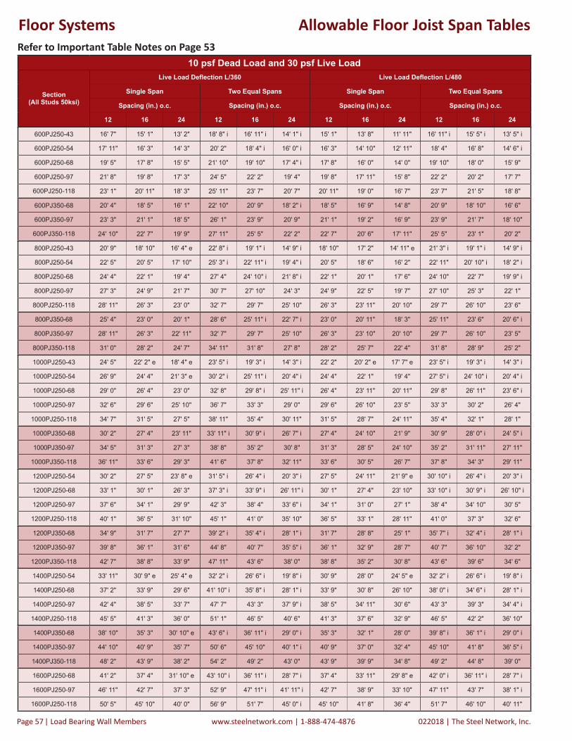
022018 | The Steel Network, Inc.www.steelnetwork.com | 1-888-474-4876Page | Load Bearing Wall Members 57
Allowable Floor Joist Span Tables
10 psf Dead Load and 30 psf Live Load
Section(All Studs 50ksi)
Live Load Deflection L/360 Live Load Deflection L/480
Single Span Two Equal Spans Single Span Two Equal Spans
Spacing (in.) o.c. Spacing (in.) o.c. Spacing (in.) o.c. Spacing (in.) o.c.
12 16 24 12 16 24 12 16 24 12 16 24
600PJ250-43 16' 7" 15' 1" 13' 2" 18' 8" i 16' 11" i 14' 1" i 15' 1" 13' 8" 11' 11" 16' 11" i 15' 5" i 13' 5" i
600PJ250-54 17' 11" 16' 3" 14' 3" 20' 2" 18' 4" i 16' 0" i 16' 3" 14' 10" 12' 11" 18' 4" 16' 8" 14' 6" i
600PJ250-68 19' 5" 17' 8" 15' 5" 21' 10" 19' 10" 17' 4" i 17' 8" 16' 0" 14' 0" 19' 10" 18' 0" 15' 9"
600PJ250-97 21' 8" 19' 8" 17' 3" 24' 5" 22' 2" 19' 4" 19' 8" 17' 11" 15' 8" 22' 2" 20' 2" 17' 7"
600PJ250-118 23' 1" 20' 11" 18' 3" 25' 11" 23' 7" 20' 7" 20' 11" 19' 0" 16' 7" 23' 7" 21' 5" 18' 8"
600PJ350-68 20' 4" 18' 5" 16' 1" 22' 10" 20' 9" 18' 2" i 18' 5" 16' 9" 14' 8" 20' 9" 18' 10" 16' 6"
600PJ350-97 23' 3" 21' 1" 18' 5" 26' 1" 23' 9" 20' 9" 21' 1" 19' 2" 16' 9" 23' 9" 21' 7" 18' 10"
600PJ350-118 24' 10" 22' 7" 19' 9" 27' 11" 25' 5" 22' 2" 22' 7" 20' 6" 17' 11" 25' 5" 23' 1" 20' 2"
800PJ250-43 20' 9" 18' 10" 16' 4" e 22' 8" i 19' 1" i 14' 9" i 18' 10" 17' 2" 14' 11" e 21' 3" i 19' 1" i 14' 9" i
800PJ250-54 22' 5" 20' 5" 17' 10" 25' 3" i 22' 11" i 19' 4" i 20' 5" 18' 6" 16' 2" 22' 11" 20' 10" i 18' 2" i
800PJ250-68 24' 4" 22' 1" 19' 4" 27' 4" 24' 10" i 21' 8" i 22' 1" 20' 1" 17' 6" 24' 10" 22' 7" 19' 9" i
800PJ250-97 27' 3" 24' 9" 21' 7" 30' 7" 27' 10" 24' 3" 24' 9" 22' 5" 19' 7" 27' 10" 25' 3" 22' 1"
800PJ250-118 28' 11" 26' 3" 23' 0" 32' 7" 29' 7" 25' 10" 26' 3" 23' 11" 20' 10" 29' 7" 26' 10" 23' 6"
800PJ350-68 25' 4" 23' 0" 20' 1" 28' 6" 25' 11" i 22' 7" i 23' 0" 20' 11" 18' 3" 25' 11" 23' 6" 20' 6" i
800PJ350-97 28' 11" 26' 3" 22' 11" 32' 7" 29' 7" 25' 10" 26' 3" 23' 10" 20' 10" 29' 7" 26' 10" 23' 5"
800PJ350-118 31' 0" 28' 2" 24' 7" 34' 11" 31' 8" 27' 8" 28' 2" 25' 7" 22' 4" 31' 8" 28' 9" 25' 2"
1000PJ250-43 24' 5" 22' 2" e 18' 4" e 23' 5" i 19' 3" i 14' 3" i 22' 2" 20' 2" e 17' 7" e 23' 5" i 19' 3" i 14' 3" i
1000PJ250-54 26' 9" 24' 4" 21' 3" e 30' 2" i 25' 11" i 20' 4" i 24' 4" 22' 1" 19' 4" 27' 5" i 24' 10" i 20' 4" i
1000PJ250-68 29' 0" 26' 4" 23' 0" 32' 8" 29' 8" i 25' 11" i 26' 4" 23' 11" 20' 11" 29' 8" 26' 11" 23' 6" i
1000PJ250-97 32' 6" 29' 6" 25' 10" 36' 7" 33' 3" 29' 0" 29' 6" 26' 10" 23' 5" 33' 3" 30' 2" 26' 4"
1000PJ250-118 34' 7" 31' 5" 27' 5" 38' 11" 35' 4" 30' 11" 31' 5" 28' 7" 24' 11" 35' 4" 32' 1" 28' 1"
1000PJ350-68 30' 2" 27' 4" 23' 11" 33' 11" i 30' 9" i 26' 7" i 27' 4" 24' 10" 21' 9" 30' 9" 28' 0" i 24' 5" i
1000PJ350-97 34' 5" 31' 3" 27' 3" 38' 8" 35' 2" 30' 8" 31' 3" 28' 5" 24' 10" 35' 2" 31' 11" 27' 11"
1000PJ350-118 36' 11" 33' 6" 29' 3" 41' 6" 37' 8" 32' 11" 33' 6" 30' 5" 26' 7" 37' 8" 34' 3" 29' 11"
1200PJ250-54 30' 2" 27' 5" 23' 8" e 31' 5" i 26' 4" i 20' 3" i 27' 5" 24' 11" 21' 9" e 30' 10" i 26' 4" i 20' 3" i
1200PJ250-68 33' 1" 30' 1" 26' 3" 37' 3" i 33' 9" i 26' 11" i 30' 1" 27' 4" 23' 10" 33' 10" i 30' 9" i 26' 10" i
1200PJ250-97 37' 6" 34' 1" 29' 9" 42' 3" 38' 4" 33' 6" i 34' 1" 31' 0" 27' 1" 38' 4" 34' 10" 30' 5"
1200PJ250-118 40' 1" 36' 5" 31' 10" 45' 1" 41' 0" 35' 10" 36' 5" 33' 1" 28' 11" 41' 0" 37' 3" 32' 6"
1200PJ350-68 34' 9" 31' 7" 27' 7" 39' 2" i 35' 4" i 28' 1" i 31' 7" 28' 8" 25' 1" 35' 7" i 32' 4" i 28' 1" i
1200PJ350-97 39' 8" 36' 1" 31' 6" 44' 8" 40' 7" 35' 5" i 36' 1" 32' 9" 28' 7" 40' 7" 36' 10" 32' 2"
1200PJ350-118 42' 7" 38' 8" 33' 9" 47' 11" 43' 6" 38' 0" 38' 8" 35' 2" 30' 8" 43' 6" 39' 6" 34' 6"
1400PJ250-54 33' 11" 30' 9" e 25' 4" e 32' 2" i 26' 6" i 19' 8" i 30' 9" 28' 0" 24' 5" e 32' 2" i 26' 6" i 19' 8" i
1400PJ250-68 37' 2" 33' 9" 29' 6" 41' 10" i 35' 8" i 28' 1" i 33' 9" 30' 8" 26' 10" 38' 0" i 34' 6" i 28' 1" i
1400PJ250-97 42' 4" 38' 5" 33' 7" 47' 7" 43' 3" 37' 9" i 38' 5" 34' 11" 30' 6" 43' 3" 39' 3" 34' 4" i
1400PJ250-118 45' 5" 41' 3" 36' 0" 51' 1" 46' 5" 40' 6" 41' 3" 37' 6" 32' 9" 46' 5" 42' 2" 36' 10"
1400PJ350-68 38' 10" 35' 3" 30' 10" e 43' 6" i 36' 11" i 29' 0" i 35' 3" 32' 1" 28' 0" 39' 8" i 36' 1" i 29' 0" i
1400PJ350-97 44' 10" 40' 9" 35' 7" 50' 6" 45' 10" 40' 1" i 40' 9" 37' 0" 32' 4" 45' 10" 41' 8" 36' 5" i
1400PJ350-118 48' 2" 43' 9" 38' 2" 54' 2" 49' 2" 43' 0" 43' 9" 39' 9" 34' 8" 49' 2" 44' 8" 39' 0"
1600PJ250-68 41' 2" 37' 4" 31' 10" e 43' 10" i 36' 11" i 28' 7" i 37' 4" 33' 11" 29' 8" e 42' 0" i 36' 11" i 28' 7" i
1600PJ250-97 46' 11" 42' 7" 37' 3" 52' 9" 47' 11" i 41' 11" i 42' 7" 38' 9" 33' 10" 47' 11" 43' 7" 38' 1" i
1600PJ250-118 50' 5" 45' 10" 40' 0" 56' 9" 51' 7" 45' 0" i 45' 10" 41' 8" 36' 4" 51' 7" 46' 10" 40' 11"
Refer to Important Table Notes on Page 53
Floor Systems

The Steel Network, Inc. | 022018 www.steelnetwork.com | 1-888-474-4876 Load Bearing Wall Members | Page 58
Allowable Floor Joist Span Tables
10 psf Dead Load and 40 psf Live Load
Section(All Studs 50ksi)
Live Load Deflection L/360 Live Load Deflection L/480
Single Span Two Equal Spans Single Span Two Equal Spans
Spacing (in.) o.c. Spacing (in.) o.c. Spacing (in.) o.c. Spacing (in.) o.c.
12 16 24 12 16 24 12 16 24 12 16 24
600PJ250-43 15' 1" 13' 8" 11' 11" e 16' 11" i 15' 5" i 12' 4" i 13' 8" 12' 5" 10' 10" 15' 5" i 14' 0" i 12' 2" i
600PJ250-54 16' 3" 14' 10" 12' 11" 18' 4" i 16' 8" i 14' 6" i 14' 10" 13' 5" 11' 9" 16' 8" 15' 1" i 13' 2" i
600PJ250-68 17' 8" 16' 0" 14' 0" 19' 10" 18' 0" 15' 9" i 16' 0" 14' 7" 12' 8" 18' 0" 16' 4" 14' 4" i
600PJ250-97 19' 8" 17' 11" 15' 8" 22' 2" 20' 2" 17' 7" 17' 11" 16' 3" 14' 2" 20' 2" 18' 4" 16' 0"
600PJ250-118 20' 11" 19' 0" 16' 7" 23' 7" 21' 5" 18' 8" 19' 0" 17' 3" 15' 1" 21' 5" 19' 5" 17' 0"
600PJ350-68 18' 5" 16' 9" 14' 8" 20' 9" 18' 10" 16' 6" i 16' 9" 15' 3" 13' 4" 18' 10" 17' 2" 15' 0" i
600PJ350-97 21' 1" 19' 2" 16' 9" 23' 9" 21' 7" 18' 10" 19' 2" 17' 5" 15' 2" 21' 7" 19' 7" 17' 1"
600PJ350-118 22' 7" 20' 6" 17' 11" 25' 5" 23' 1" 20' 2" 20' 6" 18' 8" 16' 3" 23' 1" 20' 11" 18' 4"
800PJ250-43 18' 10" 17' 2" e 14' 7" e 19' 10" i 16' 7" i 12' 8" i 17' 2" 15' 7" 13' 7" e 19' 3" i 16' 7" i 12' 8" i
800PJ250-54 20' 5" 18' 6" 16' 2" 22' 11" i 20' 10" i 17' 1" i 18' 6" 16' 10" 14' 8" 20' 10" i 18' 11" i 16' 6" i
800PJ250-68 22' 1" 20' 1" 17' 6" 24' 10" 22' 7" i 19' 9" i 20' 1" 18' 3" 15' 11" 22' 7" 20' 6" 17' 11" i
800PJ250-97 24' 9" 22' 5" 19' 7" 27' 10" 25' 3" 22' 1" 22' 5" 20' 5" 17' 10" 25' 3" 22' 11" 20' 0"
800PJ250-118 26' 3" 23' 11" 20' 10" 29' 7" 26' 10" 23' 6" 23' 11" 21' 8" 18' 11" 26' 10" 24' 5" 21' 4"
800PJ350-68 23' 0" 20' 11" 18' 3" 25' 11" 23' 6" i 20' 6" i 20' 11" 19' 0" 16' 7" 23' 6" 21' 4" 18' 8" i
800PJ350-97 26' 3" 23' 10" 20' 10" 29' 7" 26' 10" 23' 5" 23' 10" 21' 8" 18' 11" 26' 10" 24' 5" 21' 4"
800PJ350-118 28' 2" 25' 7" 22' 4" 31' 8" 28' 9" 25' 2" 25' 7" 23' 3" 20' 4" 28' 9" 26' 2" 22' 10"
1000PJ250-43 22' 2" e 20' 1" e 16' 5" e 20' 1" i 16' 4" i 11' 11" i 20' 2" 18' 3" e 16' 0" e 20' 1" i 16' 4" i 11' 11" i
1000PJ250-54 24' 4" 22' 1" 19' 4" e 26' 11" i 22' 9" i 17' 8" i 22' 1" 20' 1" 17' 6" e 24' 10" i 22' 7" i 17' 8" i
1000PJ250-68 26' 4" 23' 11" 20' 11" 29' 8" i 26' 11" i 23' 4" i 23' 11" 21' 9" 19' 0" 26' 11" 24' 6" i 21' 5" i
1000PJ250-97 29' 6" 26' 10" 23' 5" 33' 3" 30' 2" 26' 4" 26' 10" 24' 4" 21' 3" 30' 2" 27' 5" 23' 11"
1000PJ250-118 31' 5" 28' 7" 24' 11" 35' 4" 32' 1" 28' 1" 28' 7" 25' 11" 22' 8" 32' 1" 29' 2" 25' 6"
1000PJ350-68 27' 4" 24' 10" 21' 9" 30' 9" i 28' 0" i 23' 6" i 24' 10" 22' 7" 19' 9" 28' 0" 25' 5" i 22' 2" i
1000PJ350-97 31' 3" 28' 5" 24' 10" 35' 2" 31' 11" 27' 11" i 28' 5" 25' 9" 22' 6" 31' 11" 29' 0" 25' 4"
1000PJ350-118 33' 6" 30' 5" 26' 7" 37' 8" 34' 3" 29' 11" 30' 5" 27' 8" 24' 2" 34' 3" 31' 1" 27' 2"
1200PJ250-54 27' 5" 24' 11" e 21' 2" e 27' 5" i 22' 10" i 17' 3" i 24' 11" 22' 8" 19' 9" e 27' 5" i 22' 10" i 17' 3" i
1200PJ250-68 30' 1" 27' 4" 23' 10" 33' 10" i 29' 10" i 23' 8" i 27' 4" 24' 10" 21' 8" 30' 9" i 27' 11" i 23' 8" i
1200PJ250-97 34' 1" 31' 0" 27' 1" 38' 4" 34' 10" 30' 5" i 31' 0" 28' 2" 24' 7" 34' 10" 31' 8" 27' 8"
1200PJ250-118 36' 5" 33' 1" 28' 11" 41' 0" 37' 3" 32' 6" 33' 1" 30' 1" 26' 3" 37' 3" 33' 10" 29' 6"
1200PJ350-68 31' 7" 28' 8" 25' 1" e 35' 7" i 31' 2" i 24' 8" i 28' 8" 26' 1" 22' 9" 32' 4" i 29' 4" i 24' 8" i
1200PJ350-97 36' 1" 32' 9" 28' 7" 40' 7" 36' 10" 32' 2" i 32' 9" 29' 9" 26' 0" 36' 10" 33' 6" 29' 3" i
1200PJ350-118 38' 8" 35' 2" 30' 8" 43' 6" 39' 6" 34' 6" 35' 2" 31' 11" 27' 11" 39' 6" 35' 11" 31' 4"
1400PJ250-54 30' 9" e 27' 9" e 22' 8" e 27' 9" i 22' 7" i 16' 6" i 28' 0" 25' 5" e 22' 2" e 27' 9" i 22' 7" i 16' 6" i
1400PJ250-68 33' 9" 30' 8" 26' 10" e 37' 0" i 31' 4" i 24' 6" i 30' 8" 27' 11" 24' 4" e 34' 6" i 31' 4" i 24' 6" i
1400PJ250-97 38' 5" 34' 11" 30' 6" 43' 3" 39' 3" i 34' 4" i 34' 11" 31' 9" 27' 8" 39' 3" 35' 8" 31' 2" i
1400PJ250-118 41' 3" 37' 6" 32' 9" 46' 5" 42' 2" 36' 10" i 37' 6" 34' 1" 29' 9" 42' 2" 38' 4" 33' 5"
1400PJ350-68 35' 3" 32' 1" 27' 11" e 38' 4" i 32' 5" i 25' 2" i 32' 1" 29' 1" 25' 5" e 36' 1" i 32' 5" i 25' 2" i
1400PJ350-97 40' 9" 37' 0" 32' 4" 45' 10" 41' 8" i 36' 5" i 37' 0" 33' 8" 29' 5" 41' 8" 37' 10" 33' 1" i
1400PJ350-118 43' 9" 39' 9" 34' 8" 49' 2" 44' 8" 39' 0" i 39' 9" 36' 1" 31' 6" 44' 8" 40' 7" 35' 6"
1600PJ250-68 37' 4" 33' 11" 28' 5" e 38' 5" i 32' 2" i 24' 7" i 33' 11" 30' 10" 26' 11" e 38' 2" i 32' 2" i 24' 7" i
1600PJ250-97 42' 7" 38' 9" 33' 10" 47' 11" 43' 7" i 38' 0" i 38' 9" 35' 2" 30' 9" 43' 7" 39' 7" 34' 7" i
1600PJ250-118 45' 10" 41' 8" 36' 4" 51' 7" 46' 10" 40' 11" i 41' 8" 37' 10" 33' 0" 46' 10" 42' 7" 37' 2"
Refer to Important Table Notes on Page 53
Floor Systems

022018 | The Steel Network, Inc.www.steelnetwork.com | 1-888-474-4876Page | Load Bearing Wall Members 59
Allowable Floor Joist Span Tables
10 psf Dead Load and 50 psf Live Load
Section(All Studs 50ksi)
Live Load Deflection L/360 Live Load Deflection L/480
Single Span Two Equal Spans Single Span Two Equal Spans
Spacing (in.) o.c. Spacing (in.) o.c. Spacing (in.) o.c. Spacing (in.) o.c.
12 16 24 12 16 24 12 16 24 12 16 24
600PJ250-43 14' 0" 12' 8" 11' 1" e 15' 9" i 14' 1" i 11' 1" i 12' 8" 11' 6" 10' 1" e 14' 3" i 13' 0" i 11' 1" i
600PJ250-54 15' 1" 13' 9" 12' 0" 17' 0" i 15' 5" i 13' 6" i 13' 9" 12' 6" 10' 11" 15' 5" 14' 0" i 12' 3" i
600PJ250-68 16' 4" 14' 10" 13' 0" 18' 5" 16' 9" i 14' 7" i 14' 10" 13' 6" 11' 10" 16' 9" 15' 2" 13' 3" i
600PJ250-97 18' 3" 16' 7" 14' 6" 20' 7" 18' 8" 16' 4" 16' 7" 15' 1" 13' 2" 18' 8" 17' 0" 14' 10"
600PJ250-118 19' 5" 17' 8" 15' 5" 21' 10" 19' 10" 17' 4" 17' 8" 16' 0" 14' 0" 19' 10" 18' 0" 15' 9"
600PJ350-68 17' 2" 15' 7" 13' 7" 19' 3" 17' 6" i 15' 3" i 15' 7" 14' 2" 12' 4" 17' 6" 15' 11" 13' 11" i
600PJ350-97 19' 7" 17' 9" 15' 6" 22' 0" 20' 0" 17' 6" 17' 9" 16' 2" 14' 1" 20' 0" 18' 2" 15' 10"
600PJ350-118 20' 11" 19' 0" 16' 7" 23' 7" 21' 5" 18' 8" 19' 0" 17' 3" 15' 1" 21' 5" 19' 5" 17' 0"
800PJ250-43 17' 6" 15' 11" e 13' 4" e 17' 9" i 14' 9" i 11' 2" a 15' 11" 14' 5" e 12' 7" e 17' 9" i 14' 9" i 11' 2" a
800PJ250-54 18' 11" 17' 2" 15' 0" e 21' 4" i 19' 4" i 15' 4" i 17' 2" 15' 7" 13' 8" 19' 4" i 17' 7" i 15' 4" i
800PJ250-68 20' 6" 18' 8" 16' 3" 23' 1" i 20' 11" i 18' 4" i 18' 8" 16' 11" 14' 9" 20' 11" 19' 0" i 16' 7" i
800PJ250-97 22' 11" 20' 10" 18' 2" 25' 10" 23' 5" 20' 6" 20' 10" 18' 11" 16' 6" 23' 5" 21' 4" 18' 7"
800PJ250-118 24' 5" 22' 2" 19' 4" 27' 5" 24' 11" 21' 9" 22' 2" 20' 2" 17' 7" 24' 11" 22' 8" 19' 9"
800PJ350-68 21' 4" 19' 5" 16' 11" 24' 0" i 21' 10" i 19' 1" i 19' 5" 17' 7" 15' 5" 21' 10" 19' 10" i 17' 4" i
800PJ350-97 24' 5" 22' 2" 19' 4" 27' 5" 24' 11" 21' 9" i 22' 2" 20' 2" 17' 7" 24' 11" 22' 8" 19' 9"
800PJ350-118 26' 2" 23' 9" 20' 9" 29' 5" 26' 9" 23' 4" 23' 9" 21' 7" 18' 10" 26' 9" 24' 3" 21' 2"
1000PJ250-43 20' 7" e 18' 4" e 14' 0" e 17' 8" i 14' 3" i 10' 2" i 18' 8" e 17' 0" e 14' 0" e 17' 8" i 14' 3" i 10' 2" i
1000PJ250-54 22' 7" 20' 6" 17' 8" e 24' 2" i 20' 4" i 15' 8" i 20' 6" 18' 8" 16' 3" e 23' 1" i 20' 4" i 15' 8" i
1000PJ250-68 24' 6" 22' 3" 19' 5" 27' 6" i 25' 0" i 21' 1" i 22' 3" 20' 2" 17' 8" 25' 0" 22' 9" i 19' 10" i
1000PJ250-97 27' 5" 24' 11" 21' 9" 30' 10" 28' 0" 24' 6" i 24' 11" 22' 7" 19' 9" 28' 0" 25' 5" 22' 3"
1000PJ250-118 29' 2" 26' 6" 23' 2" 32' 10" 29' 10" 26' 0" 26' 6" 24' 1" 21' 0" 29' 10" 27' 1" 23' 8"
1000PJ350-68 25' 5" 23' 1" 20' 2" 28' 7" i 26' 0" i 21' 3" i 23' 1" 21' 0" 18' 4" 26' 0" i 23' 7" i 20' 7" i
1000PJ350-97 29' 0" 26' 4" 23' 0" 32' 8" 29' 8" 25' 11" i 26' 4" 23' 11" 20' 11" 29' 8" 26' 11" 23' 6"
1000PJ350-118 31' 1" 28' 3" 24' 8" 35' 0" 31' 9" 27' 9" 28' 3" 25' 8" 22' 5" 31' 9" 28' 11" 25' 3"
1200PJ250-54 25' 6" 23' 2" e 19' 3" e 24' 6" i 20' 3" i 15' 1" i 23' 2" 21' 0" e 18' 4" e 24' 6" i 20' 3" i 15' 1" i
1200PJ250-68 27' 11" 25' 4" 22' 2" e 31' 5" i 26' 11" i 21' 3" i 25' 4" 23' 0" 20' 1" 28' 6" i 25' 11" i 21' 3" i
1200PJ250-97 31' 8" 28' 9" 25' 1" 35' 7" 32' 4" i 28' 3" i 28' 9" 26' 1" 22' 10" 32' 4" 29' 5" 25' 8" i
1200PJ250-118 33' 10" 30' 9" 26' 10" 38' 0" 34' 7" 30' 2" i 30' 9" 27' 11" 24' 4" 34' 7" 31' 5" 27' 5"
1200PJ350-68 29' 4" 26' 8" 23' 3" e 33' 0" i 28' 1" i 22' 1" i 26' 8" 24' 2" 21' 2" e 30' 0" i 27' 3" i 22' 1" i
1200PJ350-97 33' 6" 30' 5" 26' 7" 37' 8" 34' 2" i 29' 11" i 30' 5" 27' 7" 24' 2" 34' 2" 31' 1" 27' 2" i
1200PJ350-118 35' 11" 32' 7" 28' 6" 40' 5" 36' 8" 32' 1" i 32' 7" 29' 8" 25' 11" 36' 8" 33' 4" 29' 1"
1400PJ250-54 28' 7" e 25' 4" e 19' 7" e 24' 5" i 19' 8" i 14' 2" i 25' 11" e 23' 7" e 19' 7" e 24' 5" i 19' 8" i 14' 2" i
1400PJ250-68 31' 4" 28' 6" 24' 6" e 33' 4" i 28' 1" i 21' 9" i 28' 6" 25' 11" 22' 7" e 32' 1" i 28' 1" i 21' 9" i
1400PJ250-97 35' 8" 32' 5" 28' 4" 40' 2" 36' 5" i 31' 10" i 32' 5" 29' 5" 25' 9" 36' 5" 33' 1" 28' 11" i
1400PJ250-118 38' 4" 34' 9" 30' 5" 43' 1" 39' 2" 34' 2" i 34' 9" 31' 7" 27' 7" 39' 2" 35' 7" 31' 1"
1400PJ350-68 32' 9" 29' 9" 25' 6" e 34' 6" i 29' 0" i 22' 4" i 29' 9" 27' 0" 23' 7" e 33' 6" i 29' 0" i 22' 4" i
1400PJ350-97 37' 10" 34' 5" 30' 0" 42' 7" 38' 8" i 33' 9" i 34' 5" 31' 3" 27' 3" 38' 8" 35' 2" 30' 8" i
1400PJ350-118 40' 7" 36' 11" 32' 3" 45' 8" 41' 6" 36' 3" i 36' 11" 33' 6" 29' 3" 41' 6" 37' 8" 32' 11"
1600PJ250-68 34' 8" 31' 6" e 26' 0" e 34' 4" i 28' 7" i 21' 7" i 31' 6" 28' 7" 25' 0" e 34' 4" i 28' 7" i 21' 7" i
1600PJ250-97 39' 7" 35' 11" 31' 5" 44' 6" i 40' 5" i 34' 5" i 35' 11" 32' 8" 28' 6" 40' 5" 36' 9" i 32' 1" i
1600PJ250-118 42' 6" 38' 8" 33' 9" 47' 10" 43' 6" 38' 0" i 38' 8" 35' 1" 30' 8" 43' 6" 39' 6" 34' 6" i
Refer to Important Table Notes on Page 53
Floor Systems

The Steel Network, Inc. | 022018 www.steelnetwork.com | 1-888-474-4876 Load Bearing Wall Members | Page 60
Allowable Floor Joist Span Tables
15 psf Dead Load and 125 psf Live Load
Section(All Studs 50ksi)
Live Load Deflection L/360 Live Load Deflection L/480
Single Span Two Equal Spans Single Span Two Equal Spans
Spacing (in.) o.c. Spacing (in.) o.c. Spacing (in.) o.c. Spacing (in.) o.c.
12 16 24 12 16 24 12 16 24 12 16 24
600PJ250-43 10' 3" e 9' 2" e 7' 6" e 10' 1" a 8' 5" a 6' 4" a 9' 4" e 8' 6" e 7' 5" e 10' 1" a 8' 5" a 6' 4" a
600PJ250-54 11' 2" 10' 1" e 8' 9" e 12' 5" i 10' 7" i 8' 5" a 10' 1" 9' 2" 8' 0" e 11' 5" i 10' 4" i 8' 5" a
600PJ250-68 12' 1" 10' 11" 9' 7" 13' 7" i 12' 4" i 10' 1" i 10' 11" 9' 11" 8' 8" 12' 4" i 11' 2" i 9' 9" i
600PJ250-97 13' 6" 12' 3" 10' 8" 15' 2" 13' 9" 12' 0" i 12' 3" 11' 1" 9' 8" 13' 9" 12' 6" 10' 11" i
600PJ250-118 14' 4" 13' 0" 11' 4" 16' 1" 14' 7" 12' 9" 13' 0" 11' 10" 10' 4" 14' 7" 13' 3" 11' 7"
600PJ350-68 12' 7" 11' 5" 10' 0" e 14' 2" i 12' 11" i 10' 5" i 11' 5" 10' 5" 9' 1" 12' 11" i 11' 8" i 10' 3" i
600PJ350-97 14' 5" 13' 1" 11' 5" 16' 3" 14' 9" i 12' 10" i 13' 1" 11' 11" 10' 5" 14' 9" 13' 4" 11' 8" i
600PJ350-118 15' 5" 14' 0" 12' 3" 17' 4" 15' 9" 13' 9" i 14' 0" 12' 9" 11' 1" 15' 9" 14' 4" 12' 6"
800PJ250-43 12' 4" e 10' 8" e 7' 6" e 9' 11" a 7' 11" a 5' 7" a 11' 8" e 10' 8" e 7' 6" e 9' 11" a 7' 11" a 5' 7" a
800PJ250-54 13' 11" e 12' 7" e 10' 3" e 14' 0" i 11' 8" a 8' 11" a 12' 8" e 11' 6" e 10' 0" e 14' 0" i 11' 8" a 8' 11" a
800PJ250-68 15' 1" 13' 9" 12' 0" e 17' 0" i 14' 10" i 11' 10" a 13' 9" 12' 5" 10' 11" e 15' 5" i 14' 0" i 11' 10" a
800PJ250-97 16' 11" 15' 4" 13' 5" 19' 0" 17' 3" i 15' 1" i 15' 4" 13' 11" 12' 2" 17' 3" 15' 8" 13' 8" i
800PJ250-118 18' 0" 16' 4" 14' 3" 20' 3" 18' 4" 16' 0" i 16' 4" 14' 10" 12' 11" 18' 4" 16' 8" 14' 7"
800PJ350-68 15' 9" 14' 3" e 12' 5" e 17' 8" i 15' 3" i 12' 2" a 14' 3" 13' 0" 11' 4" e 16' 1" i 14' 7" i 12' 2" a
800PJ350-97 18' 0" 16' 4" 14' 3" 20' 2" i 18' 4" i 15' 11" i 16' 4" 14' 10" 12' 11" 18' 4" 16' 8" i 14' 7" i
800PJ350-118 19' 3" 17' 6" 15' 3" 21' 8" 19' 8" 17' 2" i 17' 6" 15' 11" 13' 10" 19' 8" 17' 10" 15' 7" i
1000PJ250-43 12' 0" e 9' 0" e 6' 0" e 8' 11" a 6' 10" a 4' 8" a 12' 0" e 9' 0" e 6' 0" e 8' 11" a 6' 10" a 4' 8" a
1000PJ250-54 16' 4" e 14' 2" e 11' 6" e 14' 2" a 11' 6" a 8' 4" a 15' 1" e 13' 9" e 11' 6" e 14' 2" a 11' 6" a 8' 4" a
1000PJ250-68 18' 0" 16' 4" e 13' 7" e 19' 4" i 16' 4" a 12' 8" a 16' 4" 14' 10" e 13' 0" e 18' 5" i 16' 4" a 12' 8" a
1000PJ250-97 20' 2" 18' 4" 16' 0" 22' 9" i 20' 8" i 18' 0" i 18' 4" 16' 8" 14' 7" 20' 8" 18' 9" i 16' 4" i
1000PJ250-118 21' 6" 19' 6" 17' 1" 24' 2" 21' 11" i 19' 2" i 19' 6" 17' 9" 15' 6" 21' 11" 19' 11" 17' 5" i
1000PJ350-68 18' 8" e 17' 0" e 14' 0" e 19' 5" i 16' 5" a 12' 9" a 17' 0" 15' 5" e 13' 6" e 19' 1" i 16' 5" a 12' 9" a
1000PJ350-97 21' 4" 19' 5" 16' 11" 24' 0" i 21' 10" i 18' 4" i 19' 5" 17' 7" 15' 5" 21' 10" i 19' 10" i 17' 4" i
1000PJ350-118 22' 11" 20' 10" 18' 2" 25' 9" 23' 5" i 20' 5" i 20' 10" 18' 11" 16' 6" 23' 5" 21' 3" 18' 7" i
1200PJ250-54 17' 10" e 14' 9" e 9' 10" e 13' 5" a 10' 7" a 7' 5" a 17' 0" e 14' 9" e 9' 10" e 13' 5" a 10' 7" a 7' 5" a
1200PJ250-68 20' 7" e 18' 4" e 14' 11" e 19' 4" i 16' 2" a 12' 3" a 18' 8" e 16' 11" e 14' 10" e 19' 4" i 16' 2" a 12' 3" a
1200PJ250-97 23' 4" 21' 2" 18' 6" e 26' 3" i 23' 10" i 19' 2" i 21' 2" 19' 3" 16' 10" 23' 10" i 21' 8" i 18' 11" i
1200PJ250-118 24' 11" 22' 7" 19' 9" 28' 0" i 25' 5" i 22' 2" i 22' 7" 20' 7" 17' 11" 25' 5" 23' 1" i 20' 2" i
1200PJ350-68 21' 7" e 18' 11" e 15' 5" e 20' 1" i 16' 8" a 12' 7" a 19' 7" e 17' 10" e 15' 5" e 20' 1" i 16' 8" a 12' 7" a
1200PJ350-97 24' 8" 22' 5" 19' 7" e 27' 9" i 25' 2" i 20' 4" a 22' 5" 20' 4" 17' 9" e 25' 2" i 22' 11" i 20' 0" i
1200PJ350-118 26' 5" 24' 0" 21' 0" 29' 9" i 27' 0" i 23' 7" i 24' 0" 21' 10" 19' 1" 27' 0" 24' 7" i 21' 5" i
1400PJ250-54 16' 10" e 12' 7" e 8' 5" e 12' 5" i 9' 7" a 6' 7" a 16' 10" e 12' 7" e 8' 5" e 12' 5" i 9' 7" a 6' 7" a
1400PJ250-68 22' 9" e 19' 8" e 16' 1" e 19' 7" i 16' 0" a 11' 9" a 21' 0" e 19' 1" e 16' 1" e 19' 7" i 16' 0" a 11' 9" a
1400PJ250-97 26' 3" 23' 10" 20' 10" e 29' 7" i 25' 7" i 20' 4" a 23' 10" 21' 8" 18' 11" e 26' 10" i 24' 5" i 20' 4" a
1400PJ250-118 28' 2" 25' 7" 22' 5" 31' 9" i 28' 10" i 24' 1" i 25' 7" 23' 3" 20' 4" 28' 10" 26' 2" i 22' 10" i
1400PJ350-68 23' 7" e 20' 5" e 16' 8" e 20' 1" a 16' 4" a 11' 11" a 21' 11" e 19' 11" e 16' 8" e 20' 1" a 16' 4" a 11' 11" a
1400PJ350-97 27' 10" 25' 4" 21' 8" e 31' 4" i 27' 4" i 21' 8" a 25' 4" 23' 0" 20' 1" e 28' 6" i 25' 10" i 21' 8" a
1400PJ350-118 29' 11" 27' 2" 23' 9" 33' 8" i 30' 7" i 26' 4" i 27' 2" 24' 8" 21' 7" 30' 7" 27' 9" i 24' 3" i
1600PJ250-68 24' 1" e 20' 10" e 14' 8" e 19' 3" i 15' 5" a 10' 11" a 23' 2" e 20' 10" e 14' 8" e 19' 3" i 15' 5" a 10' 11" a
1600PJ250-97 29' 2" 26' 6" e 22' 2" e 31' 7" i 26' 10" i 21' 0" a 26' 6" 24' 1" 21' 0" e 29' 9" i 26' 10" i 21' 0" a
1600PJ250-118 31' 4" 28' 6" 24' 10" e 35' 3" i 31' 10" i 25' 7" i 28' 6" 25' 10" 22' 7" 32' 0" i 29' 1" i 25' 5" i
Refer to Important Table Notes on Page 53
Floor Systems

022018 | The Steel Network, Inc.www.steelnetwork.com | 1-888-474-4876Page | Load Bearing Wall Members 61
Allowable Floor Joist Span Tables
40 psf Dead Load and 125 psf Live Load
Section(All Studs 50ksi)
Live Load Deflection L/360 Live Load Deflection L/480
Single Span Two Equal Spans Single Span Two Equal Spans
Spacing (in.) o.c. Spacing (in.) o.c. Spacing (in.) o.c. Spacing (in.) o.c.
12 16 24 12 16 24 12 16 24 12 16 24
600PJ250-43 9' 9" e 8' 5" e 6' 10" e 9' 1" a 7' 6" a 5' 8" a 9' 4" e 8' 5" e 6' 10" e 9' 1" a 7' 6" a 5' 8" a
600PJ250-54 11' 2" e 9' 10" e 8' 1" e 11' 4" i 9' 8" a 7' 8" a 10' 1" 9' 2" e 8' 0" e 11' 4" i 9' 8" a 7' 8" a
600PJ250-68 12' 1" 10' 11" 9' 5" e 13' 4" i 11' 5" i 9' 3" i 10' 11" 9' 11" 8' 8" e 12' 4" i 11' 2" i 9' 3" i
600PJ250-97 13' 6" 12' 3" 10' 8" 15' 2" 13' 9" i 12' 0" i 12' 3" 11' 1" 9' 8" 13' 9" 12' 6" 10' 11" i
600PJ250-118 14' 4" 13' 0" 11' 4" 16' 1" 14' 7" 12' 9" i 13' 0" 11' 10" 10' 4" 14' 7" 13' 3" 11' 7"
600PJ350-68 12' 7" 11' 5" 9' 9" e 13' 9" i 11' 10" i 9' 6" i 11' 5" 10' 5" 9' 1" e 12' 11" i 11' 8" i 9' 6" i
600PJ350-97 14' 5" 13' 1" 11' 5" 16' 3" i 14' 9" i 12' 2" i 13' 1" 11' 11" 10' 5" 14' 9" 13' 4" i 11' 8" i
600PJ350-118 15' 5" 14' 0" 12' 3" 17' 4" 15' 9" i 13' 9" i 14' 0" 12' 9" 11' 1" 15' 9" 14' 4" 12' 6" i
800PJ250-43 11' 4" e 9' 7" e 6' 5" e 8' 9" a 6' 11" a 4' 10" a 11' 4" e 9' 7" e 6' 5" e 8' 9" a 6' 11" a 4' 10" a
800PJ250-54 13' 4" e 11' 7" e 9' 5" e 12' 8" a 10' 6" a 7' 11" a 12' 8" e 11' 6" e 9' 5" e 12' 8" a 10' 6" a 7' 11" a
800PJ250-68 15' 1" 13' 7" e 11' 1" e 15' 10" i 13' 6" i 10' 9" a 13' 9" 12' 5" e 10' 11" e 15' 5" i 13' 6" i 10' 9" a
800PJ250-97 16' 11" 15' 4" 13' 5" 19' 0" i 17' 3" i 14' 10" i 15' 4" 13' 11" 12' 2" 17' 3" 15' 8" i 13' 8" i
800PJ250-118 18' 0" 16' 4" 14' 3" 20' 3" 18' 4" i 16' 0" i 16' 4" 14' 10" 12' 11" 18' 4" 16' 8" 14' 7" i
800PJ350-68 15' 9" 14' 0" e 11' 5" e 16' 4" i 13' 11" i 11' 0" a 14' 3" 13' 0" e 11' 4" e 16' 1" i 13' 11" i 11' 0" a
800PJ350-97 18' 0" 16' 4" 14' 3" 20' 2" i 18' 1" i 14' 8" i 16' 4" 14' 10" 12' 11" 18' 4" i 16' 8" i 14' 7" i
800PJ350-118 19' 3" 17' 6" 15' 3" 21' 8" i 19' 8" i 16' 11" i 17' 6" 15' 11" 13' 10" 19' 8" 17' 10" 15' 7" i
1000PJ250-43 10' 2" e 7' 7" e 5' 1" e 7' 8" a 5' 11" a 4' 0" a 10' 2" e 7' 7" e 5' 1" e 7' 8" a 5' 11" a 4' 0" a
1000PJ250-54 15' 0" e 13' 0" e 10' 1" e 12' 7" a 10' 2" a 7' 3" a 15' 0" e 13' 0" e 10' 1" e 12' 7" a 10' 2" a 7' 3" a
1000PJ250-68 17' 9" e 15' 4" e 12' 6" e 17' 7" i 14' 9" a 11' 5" a 16' 4" e 14' 10" e 12' 6" e 17' 7" i 14' 9" a 11' 5" a
1000PJ250-97 20' 2" 18' 4" 16' 0" e 22' 9" i 20' 8" i 17' 1" i 18' 4" 16' 8" 14' 7" 20' 8" i 18' 9" i 16' 4" i
1000PJ250-118 21' 6" 19' 6" 17' 1" 24' 2" i 21' 11" i 19' 2" i 19' 6" 17' 9" 15' 6" 21' 11" 19' 11" i 17' 5" i
1000PJ350-68 18' 3" e 15' 10" e 12' 11" e 17' 8" i 14' 10" a 11' 5" a 17' 0" e 15' 5" e 12' 11" e 17' 8" i 14' 10" a 11' 5" a
1000PJ350-97 21' 4" 19' 5" 16' 8" e 24' 0" i 20' 10" i 16' 10" i 19' 5" 17' 7" 15' 5" e 21' 10" i 19' 10" i 16' 10" i
1000PJ350-118 22' 11" 20' 10" 18' 2" 25' 9" i 23' 5" i 19' 7" i 20' 10" 18' 11" 16' 6" 23' 5" 21' 3" i 18' 7" i
1200PJ250-54 16' 5" e 12' 6" e 8' 4" e 11' 9" a 9' 3" a 6' 5" a 16' 5" e 12' 6" e 8' 4" e 11' 9" a 9' 3" a 6' 5" a
1200PJ250-68 19' 6" e 16' 10" e 13' 9" e 17' 6" i 14' 6" a 10' 10" a 18' 8" e 16' 10" e 13' 9" e 17' 6" i 14' 6" a 10' 10" a
1200PJ250-97 23' 4" 21' 2" 17' 9" e 25' 6" i 21' 10" i 17' 6" a 21' 2" 19' 3" 16' 10" e 23' 10" i 21' 8" i 17' 6" a
1200PJ250-118 24' 11" 22' 7" 19' 9" 28' 0" i 25' 2" i 20' 5" i 22' 7" 20' 7" 17' 11" 25' 5" i 23' 1" i 20' 2" i
1200PJ350-68 20' 1" e 17' 5" e 14' 3" e 18' 1" a 14' 11" a 11' 1" a 19' 7" e 17' 5" e 14' 3" e 18' 1" a 14' 11" a 11' 1" a
1200PJ350-97 24' 8" 22' 5" e 18' 5" e 27' 1" i 23' 3" i 18' 7" a 22' 5" 20' 4" 17' 9" e 25' 2" i 22' 11" i 18' 7" a
1200PJ350-118 26' 5" 24' 0" 21' 0" 29' 9" i 27' 0" i 22' 0" i 24' 0" 21' 10" 19' 1" 27' 0" i 24' 7" i 21' 5" i
1400PJ250-54 14' 3" e 10' 8" e 7' 1" e 10' 9" i 8' 3" a 5' 7" a 14' 3" e 10' 8" e 7' 1" e 10' 9" i 8' 3" a 5' 7" a
1400PJ250-68 20' 11" e 18' 1" e 14' 3" e 17' 6" a 14' 2" a 10' 3" a 20' 11" e 18' 1" e 14' 3" e 17' 6" a 14' 2" a 10' 3" a
1400PJ250-97 26' 3" 23' 6" e 19' 2" e 27' 4" i 23' 4" i 18' 5" a 23' 10" 21' 8" e 18' 11" e 26' 10" i 23' 4" i 18' 5" a
1400PJ250-118 28' 2" 25' 7" 22' 2" e 31' 9" i 27' 4" i 22' 1" i 25' 7" 23' 3" 20' 4" 28' 10" i 26' 2" i 22' 1" i
1400PJ350-68 21' 9" e 18' 10" e 14' 3" e 17' 11" a 14' 5" a 10' 4" a 21' 9" e 18' 10" e 14' 3" e 17' 11" a 14' 5" a 10' 4" a
1400PJ350-97 27' 10" 24' 6" e 20' 0" e 29' 4" i 24' 11" i 19' 8" a 25' 4" 23' 0" e 20' 0" e 28' 6" i 24' 11" i 19' 8" a
1400PJ350-118 29' 11" 27' 2" 23' 1" e 33' 8" i 29' 11" i 24' 1" i 27' 2" 24' 8" 21' 7" e 30' 7" i 27' 9" i 24' 1" i
1600PJ250-68 22' 2" e 18' 8" e 12' 5" e 17' 0" a 13' 5" a 9' 5" a 22' 2" e 18' 8" e 12' 5" e 17' 0" a 13' 5" a 9' 5" a
1600PJ250-97 28' 11" e 25' 1" e 20' 5" e 28' 9" i 24' 4" i 19' 0" a 26' 6" 24' 1" e 20' 5" e 28' 9" i 24' 4" i 19' 0" a
1600PJ250-118 31' 4" 28' 6" 23' 8" e 34' 0" i 29' 2" i 23' 5" i 28' 6" 25' 10" 22' 7" e 32' 0" i 29' 1" i 23' 5" i
Refer to Important Table Notes on Page 53
Floor Systems
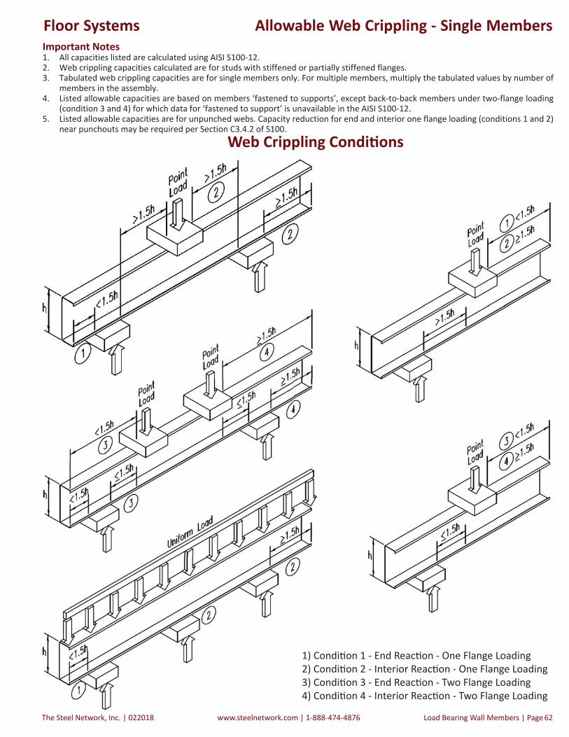
The Steel Network, Inc. | 022018 www.steelnetwork.com | 1-888-474-4876 Load Bearing Wall Members | Page 62
Allowable Web Crippling - Single MembersImportant Notes1. All capacities listed are calculated using AISI S100-12.2. Web crippling capacities calculated are for studs with stiffened or partially stiffened flanges.3. Tabulated web crippling capacities are for single members only. For multiple members, multiply the tabulated values by number of
members in the assembly.4. Listed allowable capacities are based on members ‘fastened to supports’, except back-to-back members under two-flange loading
(condition 3 and 4) for which data for ‘fastened to support’ is unavailable in the AISI S100-12.5. Listed allowable capacities are for unpunched webs. Capacity reduction for end and interior one flange loading (conditions 1 and 2)
near punchouts may be required per Section C3.4.2 of S100.
h l k | l k |
Web Crippling Condi ons
1) Condi on 1 - End Reac on - One Flange Loading2) Condi on 2 - Interior Reac on - One Flange Loading3) Condi on 3 - End Reac on - Two Flange Loading4) Condi on 4 - Interior Reac on - Two Flange Loading
Floor Systems

022018 | The Steel Network, Inc.www.steelnetwork.com | 1-888-474-4876Page | Load Bearing Wall Members 63
Allowable Web Crippling - Single MembersRefer to Important Table Notes on Page 60
1 Bearing length to web height ra o, N/h, exceeds limit of 2.0.2 Bearing length to thickness ra o, N/t, exceeds limit of 210.
Allowable Web Crippling Loads (lbs) - Single Members
Section(All Studs 50ksi)
Design Thick-ness
Inside Radius Condition 1 Condition 2 Condition 3 Condition 4
(in.) (in.) 1 3.5 4 6 1 3.5 4 6 1 3.5 4 6 1 3.5 4 6
600PJ250-43 0.0451 0.105 375 579 609 714 766 1,031 1,070 1,207 276 362 375 420 883 1,094 1,125 1,234
600PJ250-54 0.0566 0.105 586 889 934 1,091 1,239 1,638 1,698 1,904 478 617 638 710 1,457 1,776 1,824 1,988
600PJ250-68 0.0713 0.105 916 1,369 1,436 1,669 2,005 2,605 2,694 3,004 817 1,037 1,070 1,184 2,402 2,884 2,956 3,205
600PJ250-97 0.1017 0.105 1,811 2,637 2,759 3,185 4,160 5,265 5,429 5,999 1,805 2,235 2,299 2,521 5,116 6,009 6,142 6,603
600PJ250-118 0.1242 0.105 2,652 3,803 3,974 4,568 6,248 7,795 8,024 8,823 2,789 3,406 3,497 3,816 7,787 9,042 9,228 9,876
600PJ350-68 0.0713 0.105 916 1,369 1,436 1,669 2,005 2,605 2,694 3,004 817 1,037 1,070 1,184 2,402 2,884 2,956 3,205
600PJ350-97 0.1017 0.105 1,811 2,637 2,759 3,185 4,160 5,265 5,429 5,999 1,805 2,235 2,299 2,521 5,116 6,009 6,142 6,603
600PJ350-118 0.1242 0.105 2,652 3,803 3,974 4,568 6,248 7,795 8,024 8,823 2,789 3,406 3,497 3,816 7,787 9,042 9,228 9,876
800PJ250-43 0.0451 0.105 358 551 580 680 750 1,010 1,048 1,182 223 293 304 340 807 999 1,027 1,127
800PJ250-54 0.0566 0.105 562 853 896 1,046 1,216 1,609 1,667 1,869 406 524 542 603 1,350 1,646 1,690 1,843
800PJ250-68 0.0713 0.105 884 1,320 1,385 1,610 1,973 2,564 2,651 2,956 717 911 939 1,039 2,252 2,704 2,771 3,005
800PJ250-97 0.1017 0.105 1,759 2,561 2,680 3,094 4,105 5,195 5,357 5,920 1,641 2,031 2,089 2,291 4,863 5,713 5,839 6,277
800PJ250-118 0.1242 0.105 2,584 3,706 3,872 4,451 6,173 7,702 7,929 8,718 2,570 3,138 3,222 3,516 7,449 8,649 8,827 9,446
800PJ350-68 0.0713 0.105 884 1,320 1,385 1,610 1,973 2,564 2,651 2,956 717 911 939 1,039 2,252 2,704 2,771 3,005
800PJ350-97 0.1017 0.105 1,759 2,561 2,680 3,094 4,105 5,195 5,357 5,920 1,641 2,031 2,089 2,291 4,863 5,713 5,839 6,277
800PJ350-118 0.1242 0.105 2,584 3,706 3,872 4,451 6,173 7,702 7,929 8,718 2,570 3,138 3,222 3,516 7,449 8,649 8,827 9,446
1000PJ250-43 0.0451 0.105 342 527 555 651 736 991 1,029 1,160 177 233 241 270 740 916 942 1,033
1000PJ250-54 0.0566 0.105 541 821 863 1,007 1,197 1,583 1,640 1,839 343 443 458 509 1,257 1,532 1,573 1,715
1000PJ250-68 0.0713 0.105 855 1,278 1,340 1,558 1,945 2,527 2,614 2,914 630 800 825 913 2,121 2,547 2,610 2,830
1000PJ250-97 0.1017 0.105 1,714 2,495 2,610 3,013 4,057 5,134 5,294 5,851 1,496 1,853 1,906 2,089 4,643 5,453 5,574 5,992
1000PJ250-118 0.1242 0.105 2,525 3,620 3,783 4,348 6,108 7,621 7,845 8,626 2,378 2,904 2,982 3,254 7,153 8,305 8,476 9,071
1000PJ350-68 0.0713 0.105 855 1,278 1,340 1,558 1,945 2,527 2,614 2,914 630 800 825 913 2,121 2,547 2,610 2,830
1000PJ350-97 0.1017 0.105 1,714 2,495 2,610 3,013 4,057 5,134 5,294 5,851 1,496 1,853 1,906 2,089 4,643 5,453 5,574 5,992
1000PJ350-118 0.1242 0.105 2,525 3,620 3,783 4,348 6,108 7,621 7,845 8,626 2,378 2,904 2,982 3,254 7,153 8,305 8,476 9,071
1200PJ250-54 0.0566 0.105 522 792 833 972 1,179 1,559 1,616 1,812 286 369 382 425 1,172 1,429 1,467 1,600
1200PJ250-68 0.0713 0.105 830 1,239 1,300 1,512 1,919 2,494 2,580 2,876 551 700 722 799 2,003 2,405 2,465 2,672
1200PJ250-97 0.1017 0.105 1,673 2,435 2,548 2,941 4,013 5,080 5,238 5,788 1,367 1,692 1,740 1,908 4,444 5,220 5,335 5,736
1200PJ250-118 0.1242 0.105 2,471 3,543 3,703 4,256 6,050 7,548 7,770 8,543 2,206 2,693 2,766 3,018 6,886 7,996 8,160 8,733
1200PJ350-68 0.0713 0.105 830 1,239 1,300 1,512 1,919 2,494 2,580 2,876 551 700 722 799 2,003 2,405 2,465 2,672
1200PJ350-97 0.1017 0.105 1,673 2,435 2,548 2,941 4,013 5,080 5,238 5,788 1,367 1,692 1,740 1,908 4,444 5,220 5,335 5,736
1200PJ350-118 0.1242 0.105 2,471 3,543 3,703 4,256 6,050 7,548 7,770 8,543 2,206 2,693 2,766 3,018 6,886 7,996 8,160 8,733
1400PJ250-54 0.0566 0.105 505 766 805 940 1,163 1,538 1,593 1,787 234 302 312 347 1,095 1,335 1,370 1,494
1400PJ250-68 0.0713 0.105 806 1,204 1,263 1,469 1,896 2,464 2,548 2,842 479 608 627 694 1,894 2,275 2,331 2,528
1400PJ250-97 0.1017 0.105 1,635 2,380 2,491 2,875 3,974 5,029 5,186 5,731 1,248 1,545 1,589 1,742 4,262 5,006 5,117 5,501
1400PJ250-118 0.1242 0.105 2,422 3,473 3,629 4,171 5,996 7,481 7,701 8,467 2,048 2,501 2,568 2,801 6,642 7,712 7,871 8,423
1400PJ350-68 0.0713 0.105 806 1,204 1,263 1,469 1,896 2,464 2,548 2,842 479 608 627 694 1,894 2,275 2,331 2,528
1400PJ350-97 0.1017 0.105 1,635 2,380 2,491 2,875 3,974 5,029 5,186 5,731 1,248 1,545 1,589 1,742 4,262 5,006 5,117 5,501
1400PJ350-118 0.1242 0.105 2,422 3,473 3,629 4,171 5,996 7,481 7,701 8,467 2,048 2,501 2,568 2,801 6,642 7,712 7,871 8,423
1600PJ250-68 0.0713 0.105 784 1,172 1,229 1,429 1,875 2,436 2,519 2,809 412 523 540 597 1,794 2,154 2,207 2,393
1600PJ250-97 0.1017 0.105 1,600 2,329 2,437 2,814 3,937 4,983 5,138 5,678 1,137 1,408 1,448 1,588 4,093 4,808 4,914 5,283
1600PJ250-118 0.1242 0.105 2,377 3,408 3,561 4,093 5,946 7,418 7,637 8,397 1,901 2,321 2,384 2,601 6,415 7,449 7,602 8,136
Floor Systems

The Steel Network, Inc. | 022018 www.steelnetwork.com | 1-888-474-4876 Load Bearing Wall Members | Page 64
Allowable Web Crippling Loads (lbs) - Back-to-Back Members
Section(All Studs 50ksi)
Design Thick-ness
Inside Radius Condition 1 Condition 2 Condition 3 Condition 4
(in.) (in.) 1 3.5 4 6 1 3.5 4 6 1 3.5 4 6 1 3.5 4 6
600PJ250-43 0.0451 0.105 917 1,371 1,438 1,6721 1,324 1,718 1,776 1,9791 515 638 656 7191 1,091 1,351 1,389 1,5231
600PJ250-54 0.0566 0.105 1,397 2,055 2,152 2,4921 2,087 2,662 2,747 3,0441 872 1,064 1,092 1,1911 1,869 2,279 2,339 2,5511
600PJ250-68 0.0713 0.105 2,142 3,097 3,238 3,7311 3,307 4,147 4,272 4,7061 1,469 1,764 1,807 1,9591 3,179 3,817 3,912 4,2411
600PJ250-97 0.1017 0.105 4,134 5,818 6,067 6,9361 6,690 8,184 8,406 9,1771 3,204 3,764 3,847 4,1361 7,026 8,254 8,436 9,0691
600PJ250-118 0.1242 0.105 5,989 8,298 8,641 9,8331 9,935 11,993 12,299 13,3611 4,930 5,724 5,842 6,2521 10,876 12,628 12,888 13,7931
600PJ350-68 0.0713 0.105 2,142 3,097 3,238 3,7311 3,307 4,147 4,272 4,7061 1,469 1,764 1,807 1,9591 3,179 3,817 3,912 4,2411
600PJ350-97 0.1017 0.105 4,134 5,818 6,067 6,9361 6,690 8,184 8,406 9,1771 3,204 3,764 3,847 4,1361 7,026 8,254 8,436 9,0691
600PJ350-118 0.1242 0.105 5,989 8,298 8,641 9,8331 9,935 11,993 12,299 13,3611 4,930 5,724 5,842 6,2521 10,876 12,628 12,888 13,7931
800PJ250-43 0.0451 0.105 915 1,368 1,435 1,669 1,322 1,715 1,773 1,976 447 553 569 624 946 1,171 1,205 1,321
800PJ250-54 0.0566 0.105 1,395 2,051 2,149 2,487 2,084 2,658 2,743 3,039 777 948 973 1,061 1,666 2,031 2,085 2,273
800PJ250-68 0.0713 0.105 2,139 3,092 3,234 3,726 3,302 4,141 4,266 4,699 1,336 1,604 1,644 1,782 2,891 3,472 3,558 3,857
800PJ250-97 0.1017 0.105 4,129 5,810 6,060 6,927 6,682 8,174 8,396 9,166 2,981 3,502 3,579 3,848 6,537 7,679 7,848 8,437
800PJ250-118 0.1242 0.105 5,983 8,289 8,631 9,822 9,924 11,980 12,285 13,346 4,630 5,377 5,487 5,872 10,216 11,861 12,106 12,955
800PJ350-68 0.0713 0.105 2,139 3,092 3,234 3,726 3,302 4,141 4,266 4,699 1,336 1,604 1,644 1,782 2,891 3,472 3,558 3,857
800PJ350-97 0.1017 0.105 4,129 5,810 6,060 6,927 6,682 8,174 8,396 9,166 2,981 3,502 3,579 3,848 6,537 7,679 7,848 8,437
800PJ350-118 0.1242 0.105 5,983 8,289 8,631 9,822 9,924 11,980 12,285 13,346 4,630 5,377 5,487 5,872 10,216 11,861 12,106 12,955
1000PJ250-43 0.0451 0.105 914 1,366 1,433 1,667 1,320 1,712 1,770 1,972 387 479 493 540 819 1,014 1,043 1,144
1000PJ250-54 0.0566 0.105 1,393 2,048 2,145 2,484 2,081 2,654 2,739 3,035 694 846 869 947 1,487 1,813 1,862 2,030
1000PJ250-68 0.0713 0.105 2,136 3,088 3,230 3,721 3,298 4,136 4,260 4,693 1,219 1,464 1,501 1,627 2,639 3,169 3,248 3,521
1000PJ250-97 0.1017 0.105 4,125 5,804 6,053 6,920 6,675 8,165 8,387 9,156 2,786 3,272 3,345 3,596 6,109 7,176 7,334 7,884
1000PJ250-118 0.1242 0.105 5,977 8,281 8,623 9,812 9,914 11,968 12,273 13,333 4,369 5,073 5,177 5,540 9,638 11,191 11,421 12,223
1000PJ350-68 0.0713 0.105 2,136 3,088 3,230 3,721 3,298 4,136 4,260 4,693 1,219 1,464 1,501 1,627 2,639 3,169 3,248 3,521
1000PJ350-97 0.1017 0.105 4,125 5,804 6,053 6,920 6,675 8,165 8,387 9,156 2,786 3,272 3,345 3,596 6,109 7,176 7,334 7,884
1000PJ350-118 0.1242 0.105 5,977 8,281 8,623 9,812 9,914 11,968 12,273 13,333 4,369 5,073 5,177 5,540 9,638 11,191 11,421 12,223
1200PJ250-54 0.0566 0.105 1,391 2,046 2,143 2,481 2,078 2,651 2,735 3,031 619 755 775 845 1,327 1,617 1,660 1,811
1200PJ250-68 0.0713 0.105 2,134 3,085 3,226 3,717 3,294 4,131 4,255 4,687 1,115 1,338 1,372 1,487 2,412 2,897 2,969 3,219
1200PJ250-97 0.1017 0.105 4,121 5,798 6,047 6,913 6,668 8,158 8,378 9,147 2,610 3,066 3,134 3,369 5,723 6,723 6,871 7,387
1200PJ250-118 0.1242 0.105 5,971 8,274 8,615 9,804 9,906 11,958 12,262 13,321 4,133 4,799 4,898 5,242 9,119 10,588 10,806 11,564
1200PJ350-68 0.0713 0.105 2,134 3,085 3,226 3,717 3,294 4,131 4,255 4,687 1,115 1,338 1,372 1,487 2,412 2,897 2,969 3,219
1200PJ350-97 0.1017 0.105 4,121 5,798 6,047 6,913 6,668 8,158 8,378 9,147 2,610 3,066 3,134 3,369 5,723 6,723 6,871 7,387
1200PJ350-118 0.1242 0.105 5,971 8,274 8,615 9,804 9,906 11,958 12,262 13,321 4,133 4,799 4,898 5,242 9,119 10,588 10,806 11,564
1400PJ250-54 0.0566 0.105 1,389 2,043 2,140 2,478 2,076 2,647 2,732 3,027 550 671 689 751 1,179 1,438 1,476 1,609
1400PJ250-68 0.0713 0.105 2,131 3,081 3,222 3,713 3,291 4,127 4,251 4,682 1,018 1,223 1,253 1,359 2,204 2,647 2,713 2,941
1400PJ250-97 0.1017 0.105 4,117 5,793 6,042 6,907 6,662 8,150 8,371 9,139 2,449 2,877 2,940 3,161 5,370 6,308 6,447 6,931
1400PJ250-118 0.1242 0.105 5,967 8,267 8,608 9,796 9,898 11,948 12,252 13,310 3,918 4,549 4,642 4,968 8,643 10,035 10,242 10,960
1400PJ350-68 0.0713 0.105 2,131 3,081 3,222 3,713 3,291 4,127 4,251 4,682 1,018 1,223 1,253 1,359 2,204 2,647 2,713 2,941
1400PJ350-97 0.1017 0.105 4,117 5,793 6,042 6,907 6,662 8,150 8,371 9,139 2,449 2,877 2,940 3,161 5,370 6,308 6,447 6,931
1400PJ350-118 0.1242 0.105 5,967 8,267 8,608 9,796 9,898 11,948 12,252 13,310 3,918 4,549 4,642 4,968 8,643 10,035 10,242 10,960
1600PJ250-68 0.0713 0.105 2,129 3,078 3,219 3,709 3,287 4,123 4,247 4,678 929 1,116 1,143 1,240 2,011 2,415 2,475 2,683
1600PJ250-97 0.1017 0.105 4,114 5,788 6,037 6,901 6,657 8,143 8,364 9,131 2,299 2,701 2,760 2,968 5,042 5,922 6,053 6,507
1600PJ250-118 0.1242 0.105 5,962 8,261 8,602 9,788 9,890 11,939 12,243 13,300 3,717 4,316 4,405 4,714 8,201 9,522 9,718 10,400
Allowable Web Crippling - Back-to-Back Members
Refer to Important Table Notes on Page 60
1 Bearing length to web height ra o, N/h, exceeds limit of 1.0.2 Bearing length to thickness ra o, N/t, exceeds limit of 210.
Floor Systems
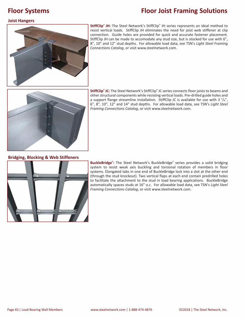
022018 | The Steel Network, Inc.www.steelnetwork.com | 1-888-474-4876Page | Load Bearing Wall Members 65
Floor Joist Framing Solutions
StiffClip® JH: The Steel Network’s StiffClip® JH series represents an ideal method to resist vertical loads. StiffClip JH eliminates the need for joist web stiffener at clip connection. Guide holes are provided for quick and accurate fastener placement. StiffClip JH can be made to accomodate any stud size, but is stocked for use with 6", 8", 10" and 12" stud depths. For allowable load data, see TSN’s Light Steel Framing Connections Catalog, or visit www.steelnetwork.com.
StiffClip® JC: The Steel Network’s StiffClip® JC series connects floor joists to beams and other structural components while resisting vertical loads. Pre-drilled guide holes and a support flange streamline installation. StiffClip JC is available for use with 3 5/8”, 6", 8", 10", 12" and 14" stud depths. For allowable load data, see TSN’s Light Steel Framing Connections Catalog, or visit www.steelnetwork.com.
BuckleBridge®: The Steel Network’s BuckleBridge® series provides a solid bridging system to resist weak axis buckling and torsional rotation of members in floor systems. Elongated tabs in one end of BuckleBridge lock into a slot at the other end (through the stud knockout). Two vertical flaps at each end contain predrilled holes to facilitate the attachment to the stud in load bearing applications. BuckleBridge automatically spaces studs at 16” o.c. For allowable load data, see TSN’s Light Steel Framing Connections Catalog, or visit www.steelnetwork.com.
Joist Hangers
Bridging, Blocking & Web Stiffeners
Floor Systems

The Steel Network, Inc. | 022018 www.steelnetwork.com | 1-888-474-4876 Load Bearing Wall Members | Page 66
PrimeJoist® Example DetailsDouble Joist End Bearing Joist End Web Stiffener, Tight
Floor Joist Bridging Ledger Framing
JH, Rigid, Steel Top Flange
Stair Opening Perpendicular to Joist
Joist Bearing on LSF Below
Stair Opening Parallel to Joist
Floor Systems

022018 | The Steel Network, Inc.www.steelnetwork.com | 1-888-474-4876Page | Load Bearing Wall Members 67
SteelSmart® SystemDesign Software
Contact ASI for licensing information:Phone: (919) 645-4090Fax: (919) 645-4085Website: www.appliedscienceint.comEmail: [email protected]
The industry’s #1 tool#1 tool for the design of Members, Connections, Fasteners & Details
yg®
Order onlineOrder online at www.steelsmartsystem.com
Introduction:SteelSmart® System (SSS) provides construc on professionals with an essen al tool engineered for both fast and accurate design. SSS 7 raises the bar for light steel framing analysis and design by seamlessly integra ng the well-known analy c power of its predecessors with addi onal func onality and accessibility.Available as a complete suite, SteelSmart System 7 will streamline produc on through the design and detailing of members, connec ons, and fasteners. Available design modules include: Curtain Wall, Load Bearing Wall, X-Brace Shear Wall, Floor Framing, Roof Framing, Roof Truss, and Moment-Resis ng Short Wall. SSS 7 incorporates two Advanced Features, the Load Generator and Distributor and the Layout and Connec on Details Generator, that further aid the user in the design process.
Layout and Connec on Details GeneratorA major feature of SSS is the Layout and Connec on Details Generator. The framing layout of components is generated with connec on details that include connec on design data (clips designa ons, number of fasteners, embedment lengths, and screw pa erns). The drawing generator is included within all 7 primary design modules, and will create a detail upon successful design of components. The drawings can be printed or exported in the AutoCAD® DXF format allowing the drawings to be easily transferred into other dra ing so ware. In addi onal to the Layout and Connec on Details generator, there is also a library of component details within SSS. Details are split into 7 categories including: Curtain Wall, Load Bearing Walls, Shear Walls, Products Details, Floor Framing, Roof Framing, and LSF Systems.
d C il G
020220201818 || TThhe Steelel NNetwork, Inc.8-474-4876
Load Generator and DistributorThe Load Generator and Distributor tool uses the dimensions and load specifi ca on for a building to calculate the lateral wind and seismic forces according to ASCE 7 “Minimum Design Loads for Buildings and Other Structures.” Now included in the Load Generator is the IBC 2012 and ASCE 7-10 design codes for development of lateral forces and snow loads. The output from the load generator gives the laterals forces distributed between fl oor levels and the shear walls at that fl oor level. The method of distribu on considers either rigid or fl exible fl oor diaphragms, while considering torsional eff ects when rigid diaphragms are selected. Output can beexported directly into theX-Brace Shear Walldesign module or into an Excelspreadsheet.
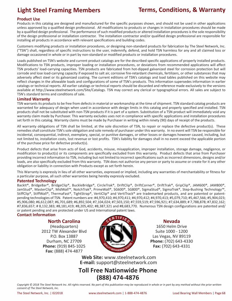
The Steel Network, Inc. | 022018 www.steelnetwork.com | 1-888-474-4876 Load Bearing Wall Members | Page 68
Terms, Conditions, & WarrantyProduct Use Products in this catalog are designed and manufactured for the specific purposes shown, and should not be used in other applications unless approved by a qualified design professional. All modifications to products or changes in installation procedures should be made by a qualified design professional. The performance of such modified products or altered installation procedures is the sole responsibility of the design professional or installation contractor. The installation contractor and/or qualified design professional are responsible for installing all products in accordance with relevant specifications and building codes.Customers modifying products or installation procedures, or designing non-standard products for fabrication by The Steel Network, Inc. ("TSN") shall, regardless of specific instructions to the user, indemnify, defend, and hold TSN harmless for any and all claimed loss or damage occasioned in whole or in part by non-standard or modified products or installation procedures.Loads published on TSN’s website and current product catalogs are for the described specific applications of properly installed products. Modifications to TSN products, improper loading or installation procedures, or deviations from recommended applications will affect TSN products' load-carrying capacities. TSN products are fabricated from hot-dipped galvanized steel for corrosion protection but will corrode and lose load-carrying capacity if exposed to salt air, corrosive fire-retardant chemicals, fertilizers, or other substances that may adversely affect steel or its galvanized coating. The current editions of TSN’s catalogs and load tables published on this website may reflect changes in the allowable loads and configurations of some of TSN's products. This information supersedes information in earlier catalogs or technical reports. All earlier catalogs or technical reports should be discarded and reference made exclusively to the versions available at http://www.steelnetwork.com/Site/Catalogs. TSN may correct any clerical or typographical errors. All sales are subject to TSN's standard terms and conditions of sale.
Patented TechnologyBackIt®, BridgeBar®, BridgeClip®, BuckleBridge®, CircleTrak®, DriftClip®, DriftCorner®, DriftTrak®, GripClip®, JAM600®, JAM800®, JamStud®, MasterClip®, MidWall™, NotchTrak®, PrimeWall®, SG600®, SG800®, SigmaStud®, SigmaTrak®, Step-Bushing Technology™, StiffClip®, StiffWall®, ThermaFast®, TightStrap®, VertiClip® and VertiTrack® are trademarked products, and are patented or patent-pending technologies of TSN. Patent numbers are: #4,970,410; #4,970,411; #4,970,412; #4,970,413; #5,079,710; #5,467,566; #5,904,023; #5,906,080; #6,612,087; #6,701,689; #6,892,504; #7,104,024; #7,503,150; #7,559,519; #7,596,921; #7,634,889; # 7,788,878; #7,832,162; #7,836,657; # 8,132,383; #8,181,419; #8,205,402; #8,387,321 and #8,683,770. Numerous TSN design configurations are patented and/or patent pending and are protected under US and International patent laws.
Limited Warranty TSN warrants its products to be free from defects in material or workmanship at the time of shipment. TSN standard catalog products are warranted for adequacy of design when used in accordance with design limits in this catalog and properly specified and installed. TSN products shall not be substituted with non-TSN products if it is part of a system. Substitution of a TSN product will immediately void any warranty claim made by Purchaser. This warranty excludes uses not in compliance with specific applications and installation procedures set forth in this catalog. Warranty claims must be made by Purchaser in writing within ninety (90) days of receipt of the products.All warranty obligations of TSN shall be limited, at the sole discretion of TSN, to repair or replace the defective product(s). These remedies shall constitute TSN's sole obligation and sole remedy of purchaser under this warranty. In no event will TSN be responsible for incidental, consequential, indirect, exemplary, special, or punitive damages, or other losses or damages however caused, including, but not limited to, installation costs, lost revenue or lost profits. TSN's liability for damages shall in no event exceed the applicable portion of the purchase price for defective product(s).Product defects that arise from acts of God, accidents, misuse, misapplication, improper installation, storage damage, negligence, or modification to product(s) or its components are specifically excluded from this warranty. Product defects that arise from Purchaser providing incorrect information to TSN, including but not limited to incorrect specifications such as incorrect dimensions, designs and/or loads, are also specifically excluded from this warranty. TSN does not authorize any person or party to assume or create for it any other obligation or liability in connection with Products except as set forth herein.This Warranty is expressly in lieu of all other warranties, expressed or implied, including any warranties of merchantability or fitness for a particular purpose, all such other warranties being hereby expressly excluded.
Toll Free Nationwide Phone (888) 474-4876
Web Site: www.steelnetwork.comE-mail: [email protected]
Copyright © 2018 The Steel Network Inc. All rights reserved. No part of this publication may be reproduced in whole or in part by any method without the prior written consent of The Steel Network, Inc.
Contact Information
(Headquarters)2012 TW Alexander Blvd
P.O. Box 13887Durham, NC 27709
Phone: (919) 845-1025Fax: (888) 474-4877
1650 Helm DriveSuite 1000 - 1200
Las Vegas, NV 89119Phone: (702) 643-4330
Fax: (702) 643-4331
North Carolina Nevada
Light Steel Framing Members
