table of contents - extranet.vdot.state.va.us€¦ · table of contents chapter 4 ... microstation...
TRANSCRIPT
VDOT CADD Manual
4-1 of 43 Table of Contents
Chapter 4 –Traffic Engineering (TED) Standards
TABLE OF CONTENTS CHAPTER 4 ................................................................................................................................................. 2
4.1 Creating Traffic Control Device Plans........................................................................... 2 4.1.1 Introduction ............................................................................................................ 2 4.1.2 Create Master Design Files and Attach all Required References ......................... 3
4.1.2.1 File Creation Instructions........................................................................ 3 4.1.2.2 Attach Reference Files ........................................................................... 6
4.1.3 Create the Individual Sheet Files ........................................................................... 9 4.1.4 Sheet File Naming Convention for TCD Plans ...................................................... 9 4.1.5 Final Stages for TCD Plan Sheets ....................................................................... 12
4.1.5.1 Referencing the necessary Traffic Files ............................................... 12 4.1.6 Complete the TCD Design in the Master Design File .......................................... 13 4.1.7 Add Labels, Notes, and Other Non-Design Elements in the Sheet File .............. 13
4.2 GuidSIGN ........................................................................................................................ 14 4.2.1 Create a new file .................................................................................................. 14 4.2.2 File Naming Convention ...................................................................................... 14 4.2.3 Loading the Program ........................................................................................... 14 4.2.4 Program Settings ................................................................................................. 14 4.2.5 Create a New Border ........................................................................................... 14 4.2.6 Text String ........................................................................................................... 15 4.2.7 Placing Cells ........................................................................................................ 15 4.2.8 Place Drawing Sheet and Report ........................................................................ 15
4.3 AGI 32 .............................................................................................................................. 16 4.3.1 Creating lighting plans ......................................................................................... 16
4.3.1.1 Exporting file from MicroStation ........................................................... 16 4.3.1.2 Create a New File in AGI32.................................................................. 16 4.3.1.3 Import File to AGI32 ............................................................................. 16 4.3.1.4 Place Calculation Points....................................................................... 17 4.3.1.5 Define a Luminaire ............................................................................... 17 4.3.1.6 Locate the Luminaires .......................................................................... 18 4.3.1.7 Lighting Calculations ............................................................................ 18 4.3.1.8 Export File ............................................................................................ 18 4.3.1.9 Import the AGI32 file into MicroStation ................................................ 18 4.3.1.10 Create Roadway Lighting Layout ......................................................... 19
4.4 TED Level Structure ...................................................................................................... 20
4.5 TED Design Guidelines .................................................................................................. 31 4.5.1 Text Font and Size............................................................................................... 31 4.5.2 Cell Libraries ........................................................................................................ 31
4.5.2.1 Overview............................................................................................... 31 4.5.3 Traffic Cell Libraries ............................................................................................. 32
4.5.3.1 List of Cell Libraries .............................................................................. 32 4.5.3.2 MicroStation Access ............................................................................. 33 4.5.3.3 Adjusting the size of the cell ................................................................. 34 4.5.3.4 Signal Pole & Controller Cabinet Legend Cells.................................... 34
4.6 Plotting with MicroStation V8i ...................................................................................... 42

VDOT CADD Manual
4-2 of 43 Traffic Control Device Plans
Chapter 4 4.1 Creating Traffic Control Device Plans
4.1.1 Introduction
This Chapter describes procedures for creating Traffic Control Device (TCD) plans using MicroStation for the Virginia Department of Transportation (VDOT). The user should refer to VDOT’s Traffic Engineering Design Manual for details on the preparation of TCD plans.
VDOT TCD Plans are developed using a combination of a ‘master design’ file and ‘sheet’ files. All TCD plans should be completed in 2D and developed by referencing CADD files from other design disciplines (roadway design, right of way, hydraulics, survey, etc.) into a master design file. A master design file is created for each type of TCD plan set required for the project (such as lighting, pavement markings, signals, signing and ITS). Individual sheet files are created for each plan sheet by referencing the master design file and the other design disciplines files.
The following directory structure should be used for all ‘t’ directories in Falcon/DMS.
UPC#\ t + UPC#\ Lighting\ PaveMark\ Signals\ Signing\ ITS\
The overall TCD plan development outline is as follows: 4.1.2 Create Master Design Files and Attach all Required References 4.1.3 Create the Individual Sheet Files
4.1.5.1 Reference the Traffic Master Design File and Other Reference Files, Rotate the View of the Sheet File, and Insert the Border Cell into the Sheet File
4.1.6 Complete the TCD Design in the Master Design File 4.1.7 Add Labels, Notes, and Other Non-Design Elements in the Sheet File

VDOT CADD Manual
4-3 of 43 Traffic Control Device Plans
4.1.2 Create Master Design Files and Attach all Required References
The master design file must be kept intact as the TCD design file for inputting all design items throughout the life of the project All proposed TCD equipment that is necessary to complete the TCD designs should be located in the master design file. Most, if not all of these items can be found in the TED cell libraries. No annotations, text, or call-outs for design items should be placed in a master design file. All annotations, text, or call-outs for design items should be placed in the sheet file along with notes, special symbols, reference notations, symbol legends, and the sheet border.
4.1.2.1 File Creation Instructions
1. All users must use SARA (VDOT”s System Access Request Application) to request access to each project. Users will be notified once access is given.
2. The user should specify the appropriate traffic sub-folders to be added to Falcon/DMS (see 4.1.1 Introduction). These sub-folders will depend on the scope of TCD design work required for the project.
3. Once Falcon/DMS access has been obtained, open Falcon/DMS Document Manager by double clicking on the Falcon Icon or by clicking on ‘Falcon/DMS’ in the MicroStation menu bar.
4. Click on ‘Database’ in the Falcon/DMS Menu bar and select ‘Open Database’.
5. Select the correct database from the pop-up window and click ‘Open’.
Note: For Internal VDOT only – There are multiple environments in the Central Office Database. Make sure the correct environment is selected by clicking on ‘Environments’ in the Falcon/DMS Menu bar and making a selection.
6. Click on the ‘Projects’ folder and select the appropriate project folder based on the UPC#.
7. Expand the project folder. There should be a folder named ‘t + UPC#’. (For example: if the UPC# is 15234. There should be a folder named t15234.)
8. Double click on the ‘t’ folder.
VDOT CADD Manual
4-4 of 43 Traffic Control Device Plans
9. The traffic sub-folders requested on the access form (see step 1) should be located in this directory. Potential sub-folders include:
a. Lighting b. PaveMark c. Signals d. Signing e. ITS
10. Click on the sub-folder where the user wants to create the file. Then click on ‘File’ in the Falcon/DMS menu bar and highlight ‘New’ and then select ‘IGDS Document’.
11. The ‘New Document’ window will pop-up with the ‘Templates’ tab selected. In this window the user now will select the appropriate seed file. TCD plans only use one of the following seed files:
• For a project using Imperial units – Select geopakdes.dgn
• For GuidSign Files – Select guidesign.dgn 12. After highlighting the correct seed file, click ‘Next’. The ‘Properties’ tab will now
be shown. The top section of the window contains fields for the ‘Filename’ and ‘Sheet #’. There are four separate tabs in the bottom half of the window:
1. General Info 2. Keywords 3. File Format Keywords 4. Title Block
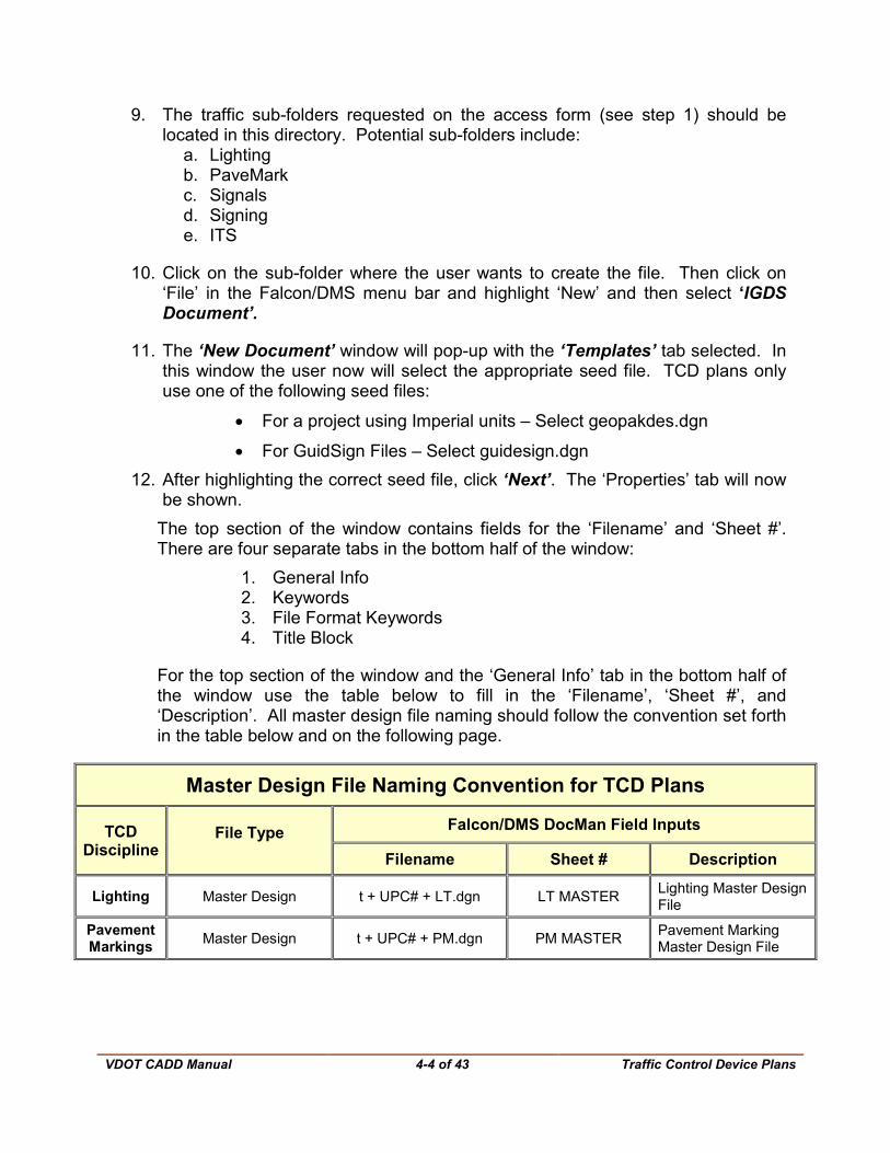
For the top section of the window and the ‘General Info’ tab in the bottom half of the window use the table below to fill in the ‘Filename’, ‘Sheet #’, and ‘Description’. All master design file naming should follow the convention set forth in the table below and on the following page.
Master Design File Naming Convention for TCD Plans
TCD Discipline
File Type Falcon/DMS DocMan Field Inputs
Filename Sheet # Description
Lighting Master Design t + UPC# + LT.dgn LT MASTER Lighting Master Design File
Pavement Markings Master Design t + UPC# + PM.dgn PM MASTER Pavement Marking
Master Design File
VDOT CADD Manual
4-5 of 43 Traffic Control Device Plans
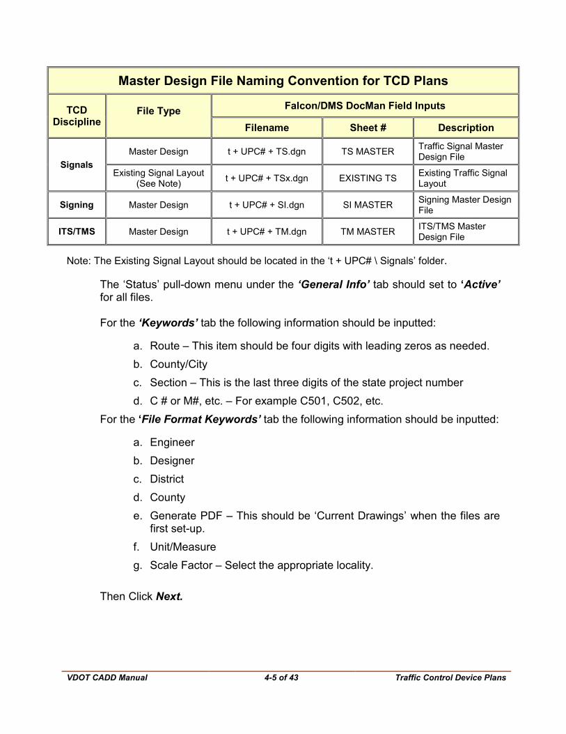
Master Design File Naming Convention for TCD Plans
TCD Discipline
File Type Falcon/DMS DocMan Field Inputs
Filename Sheet # Description
Signals Master Design t + UPC# + TS.dgn TS MASTER Traffic Signal Master
Design File
Existing Signal Layout (See Note) t + UPC# + TSx.dgn EXISTING TS Existing Traffic Signal
Layout
Signing Master Design t + UPC# + SI.dgn SI MASTER Signing Master Design File
ITS/TMS Master Design t + UPC# + TM.dgn TM MASTER ITS/TMS Master Design File
Note: The Existing Signal Layout should be located in the ‘t + UPC# \ Signals’ folder.
The ‘Status’ pull-down menu under the ‘General Info’ tab should set to ‘Active’ for all files. For the ‘Keywords’ tab the following information should be inputted:
a. Route – This item should be four digits with leading zeros as needed. b. County/City c. Section – This is the last three digits of the state project number d. C # or M#, etc. – For example C501, C502, etc.
For the ‘File Format Keywords’ tab the following information should be inputted:
a. Engineer b. Designer c. District d. County e. Generate PDF – This should be ‘Current Drawings’ when the files are
first set-up. f. Unit/Measure g. Scale Factor – Select the appropriate locality.
Then Click Next.
VDOT CADD Manual
4-6 of 43 Traffic Control Device Plans
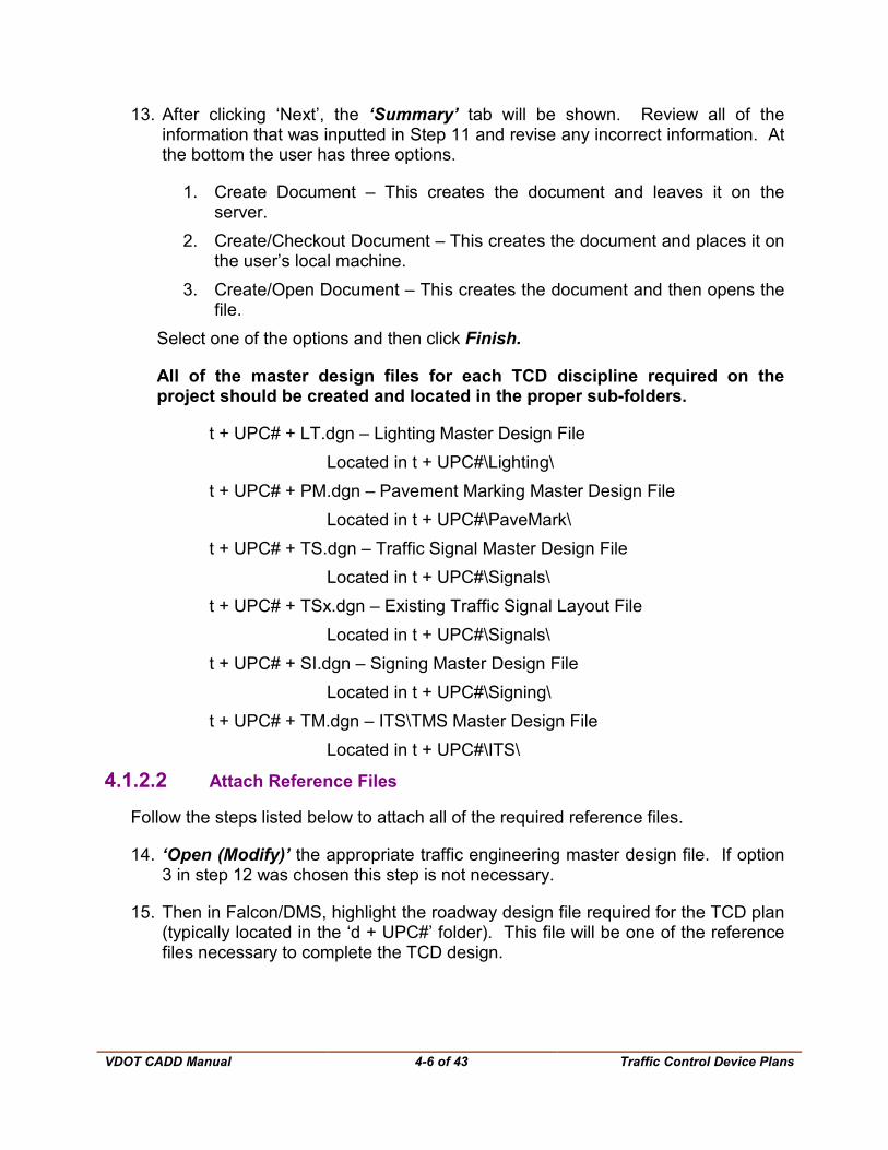
13. After clicking ‘Next’, the ‘Summary’ tab will be shown. Review all of the information that was inputted in Step 11 and revise any incorrect information. At the bottom the user has three options.
1. Create Document – This creates the document and leaves it on the server.
2. Create/Checkout Document – This creates the document and places it on the user’s local machine.
3. Create/Open Document – This creates the document and then opens the file.
Select one of the options and then click Finish.
All of the master design files for each TCD discipline required on the project should be created and located in the proper sub-folders.
t + UPC# + LT.dgn – Lighting Master Design File Located in t + UPC#\Lighting\
t + UPC# + PM.dgn – Pavement Marking Master Design File Located in t + UPC#\PaveMark\
t + UPC# + TS.dgn – Traffic Signal Master Design File Located in t + UPC#\Signals\
t + UPC# + TSx.dgn – Existing Traffic Signal Layout File Located in t + UPC#\Signals\
t + UPC# + SI.dgn – Signing Master Design File Located in t + UPC#\Signing\
t + UPC# + TM.dgn – ITS\TMS Master Design File Located in t + UPC#\ITS\
4.1.2.2 Attach Reference Files
Follow the steps listed below to attach all of the required reference files.
14. ‘Open (Modify)’ the appropriate traffic engineering master design file. If option 3 in step 12 was chosen this step is not necessary.
15. Then in Falcon/DMS, highlight the roadway design file required for the TCD plan (typically located in the ‘d + UPC#’ folder). This file will be one of the reference files necessary to complete the TCD design.
VDOT CADD Manual
4-7 of 43 Traffic Control Device Plans
16. Click ‘MicroStation’ in the Falcon/DMS menu bar and select ‘Attach Reference’.
17. In MicroStation, the ‘Attach Reference’ window will appear. Ensure the following information is shown, if not input or modify as needed:
Logical Name – Design - Roadway Description – Leave this blank Orientation – Select ‘Coincident – Aligned with Master File’ Scale (Master:Ref) – 1.000 : 1.000 Nested Attachments – Select ‘Copy Attachments’, Depth of 1
18. Click OK
All of the reference files that were attached to the master roadway design file should now be attached to the master traffic design file. The user should verify that all reference files were attached.
19. Review all of the attached files. Detach files that are not required and attach any additional files that are required to complete the traffic engineering design. Also, ensure that the corresponding roadway design sheet file(s) are attached.
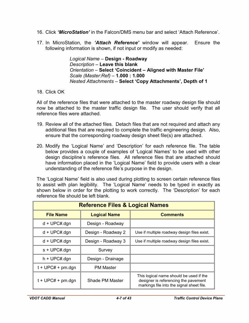
20. Modify the ‘Logical Name’ and ‘Description’ for each reference file. The table below provides a couple of examples of ‘Logical Names’ to be used with other design discipline’s reference files. All reference files that are attached should have information placed in the ‘Logical Name’ field to provide users with a clear understanding of the reference file’s purpose in the design.
The ‘Logical Name’ field is also used during plotting to screen certain reference files to assist with plan legibility. The ‘Logical Name’ needs to be typed in exactly as shown below in order for the plotting to work correctly. The ‘Description’ for each reference file should be left blank.
Reference Files & Logical Names File Name Logical Name Comments
d + UPC#.dgn Design - Roadway
d + UPC#.dgn Design - Roadway 2 Use if multiple roadway design files exist.
d + UPC#.dgn Design - Roadway 3 Use if multiple roadway design files exist.
s + UPC#.dgn Survey
h + UPC#.dgn Design - Drainage
t + UPC# + pm.dgn PM Master
t + UPC# + pm.dgn Shade PM Master This logical name should be used if the designer is referencing the pavement markings file into the signal sheet file.
VDOT CADD Manual
4-8 of 43 Traffic Control Device Plans
Although discouraged, a master design file can be used by multiple users. This requires close coordination between the various files and users. When several users need to develop their design in a master file, the recommended way to accommodate this is create multiple uniquely named master design files. It is critical that each of these files have a unique file name. This can be done by adding a qualifier to the end of the file name, such as an ‘a’ (t15234TSa.dgn). Each uniquely named master design file shall be copied into a single master design file before submittals. All sheet files should only reference the single master design file. Once the files have been combined into a single master design file, all uniquely named master design files should be deleted.
VDOT CADD Manual
4-9 of 43 Traffic Control Device Plans
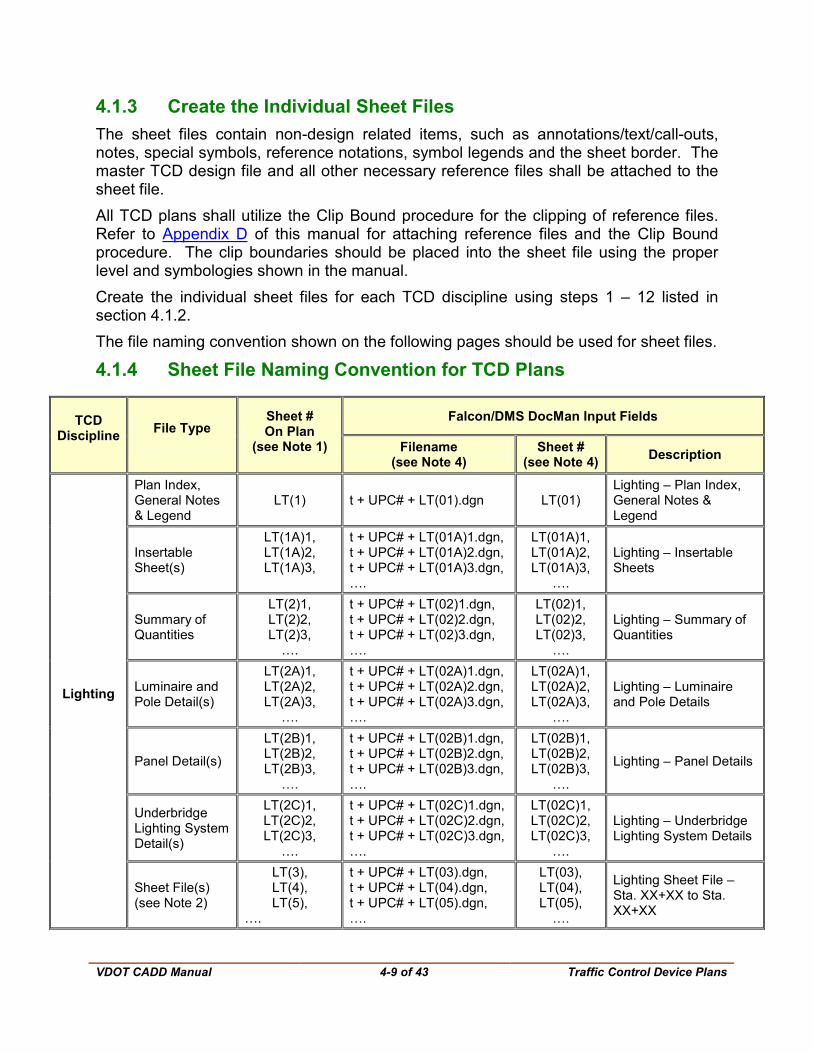
4.1.3 Create the Individual Sheet Files The sheet files contain non-design related items, such as annotations/text/call-outs, notes, special symbols, reference notations, symbol legends and the sheet border. The master TCD design file and all other necessary reference files shall be attached to the sheet file. All TCD plans shall utilize the Clip Bound procedure for the clipping of reference files. Refer to Appendix D of this manual for attaching reference files and the Clip Bound procedure. The clip boundaries should be placed into the sheet file using the proper level and symbologies shown in the manual. Create the individual sheet files for each TCD discipline using steps 1 – 12 listed in section 4.1.2. The file naming convention shown on the following pages should be used for sheet files.
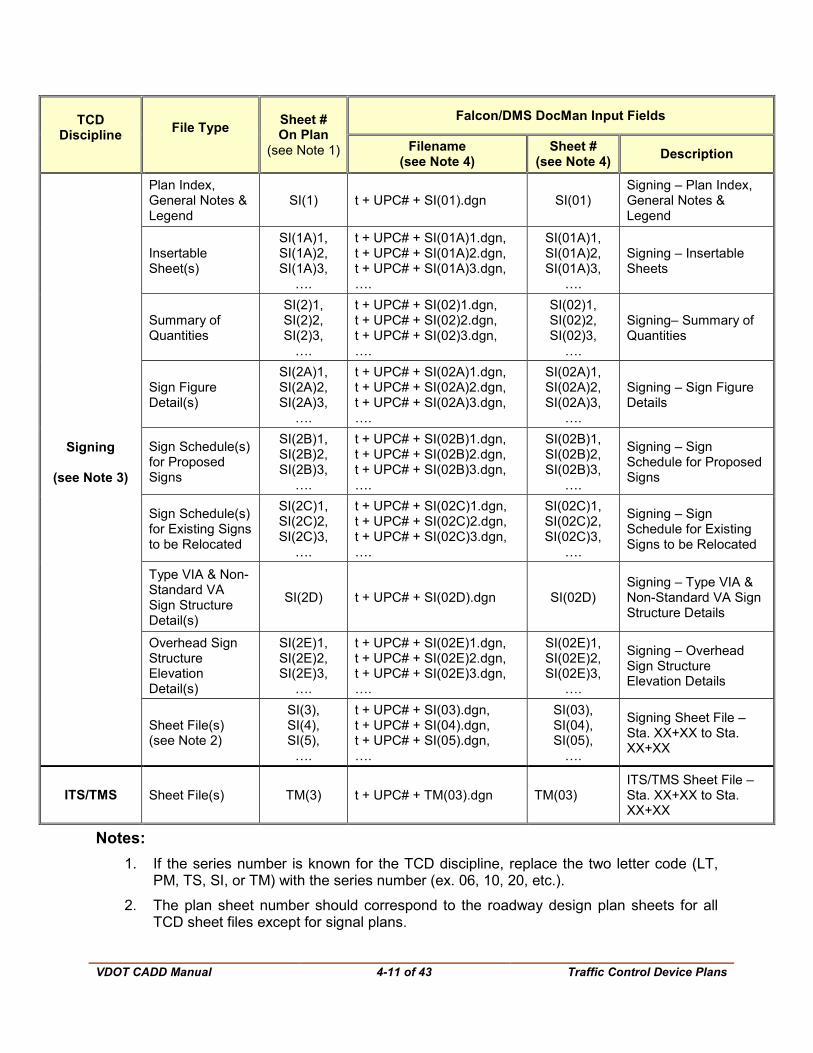
4.1.4 Sheet File Naming Convention for TCD Plans
TCD Discipline File Type
Sheet # On Plan
(see Note 1)
Falcon/DMS DocMan Input Fields
Filename (see Note 4)
Sheet # (see Note 4) Description
Lighting
Plan Index, General Notes & Legend
LT(1) t + UPC# + LT(01).dgn LT(01) Lighting – Plan Index, General Notes & Legend
Insertable Sheet(s)
LT(1A)1, LT(1A)2, LT(1A)3,
t + UPC# + LT(01A)1.dgn, t + UPC# + LT(01A)2.dgn, t + UPC# + LT(01A)3.dgn, ….
LT(01A)1, LT(01A)2, LT(01A)3,
….
Lighting – Insertable Sheets
Summary of Quantities
LT(2)1, LT(2)2, LT(2)3,
….
t + UPC# + LT(02)1.dgn, t + UPC# + LT(02)2.dgn, t + UPC# + LT(02)3.dgn, ….
LT(02)1, LT(02)2, LT(02)3,
….
Lighting – Summary of Quantities
Luminaire and Pole Detail(s)
LT(2A)1, LT(2A)2, LT(2A)3,
….
t + UPC# + LT(02A)1.dgn, t + UPC# + LT(02A)2.dgn, t + UPC# + LT(02A)3.dgn, ….
LT(02A)1, LT(02A)2, LT(02A)3,
….
Lighting – Luminaire and Pole Details
Panel Detail(s)
LT(2B)1, LT(2B)2, LT(2B)3,
….
t + UPC# + LT(02B)1.dgn, t + UPC# + LT(02B)2.dgn, t + UPC# + LT(02B)3.dgn, ….
LT(02B)1, LT(02B)2, LT(02B)3,
….
Lighting – Panel Details
Underbridge Lighting System Detail(s)
LT(2C)1, LT(2C)2, LT(2C)3,
….
t + UPC# + LT(02C)1.dgn, t + UPC# + LT(02C)2.dgn, t + UPC# + LT(02C)3.dgn, ….
LT(02C)1, LT(02C)2, LT(02C)3,
….
Lighting – Underbridge Lighting System Details
Sheet File(s) (see Note 2)
LT(3), LT(4), LT(5),
….
t + UPC# + LT(03).dgn, t + UPC# + LT(04).dgn, t + UPC# + LT(05).dgn, ….
LT(03), LT(04), LT(05),
….
Lighting Sheet File – Sta. XX+XX to Sta. XX+XX
VDOT CADD Manual
4-10 of 43 Traffic Control Device Plans
TCD Discipline File Type Sheet #
On Plan (see Note 1)
Falcon/DMS DocMan Input Fields
Filename (see Note 4)
Sheet # (see Note 4) Description
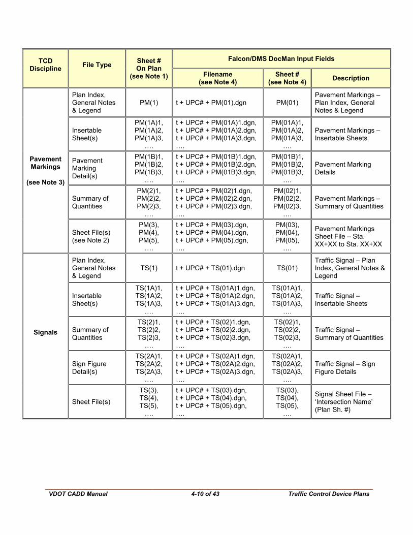
Pavement Markings
(see Note 3)
Plan Index, General Notes & Legend
PM(1) t + UPC# + PM(01).dgn PM(01) Pavement Markings – Plan Index, General Notes & Legend
Insertable Sheet(s)
PM(1A)1, PM(1A)2, PM(1A)3,
….
t + UPC# + PM(01A)1.dgn, t + UPC# + PM(01A)2.dgn, t + UPC# + PM(01A)3.dgn, ….
PM(01A)1, PM(01A)2, PM(01A)3,
….
Pavement Markings – Insertable Sheets
Pavement Marking Detail(s)
PM(1B)1, PM(1B)2, PM(1B)3,
….
t + UPC# + PM(01B)1.dgn, t + UPC# + PM(01B)2.dgn, t + UPC# + PM(01B)3.dgn, ….
PM(01B)1, PM(01B)2, PM(01B)3,
….
Pavement Marking Details
Summary of Quantities
PM(2)1, PM(2)2, PM(2)3,
….
t + UPC# + PM(02)1.dgn, t + UPC# + PM(02)2.dgn, t + UPC# + PM(02)3.dgn, ….
PM(02)1, PM(02)2, PM(02)3,
….
Pavement Markings – Summary of Quantities
Sheet File(s) (see Note 2)
PM(3), PM(4), PM(5),
….
t + UPC# + PM(03).dgn, t + UPC# + PM(04).dgn, t + UPC# + PM(05).dgn, ….
PM(03), PM(04), PM(05),
….
Pavement Markings Sheet File – Sta. XX+XX to Sta. XX+XX
Signals
Plan Index, General Notes & Legend
TS(1) t + UPC# + TS(01).dgn TS(01) Traffic Signal – Plan Index, General Notes & Legend
Insertable Sheet(s)
TS(1A)1, TS(1A)2, TS(1A)3,
….
t + UPC# + TS(01A)1.dgn, t + UPC# + TS(01A)2.dgn, t + UPC# + TS(01A)3.dgn, ….
TS(01A)1, TS(01A)2, TS(01A)3,
….
Traffic Signal – Insertable Sheets
Summary of Quantities
TS(2)1, TS(2)2, TS(2)3,
….
t + UPC# + TS(02)1.dgn, t + UPC# + TS(02)2.dgn, t + UPC# + TS(02)3.dgn, ….
TS(02)1, TS(02)2, TS(02)3,
….
Traffic Signal – Summary of Quantities
Sign Figure Detail(s)
TS(2A)1, TS(2A)2, TS(2A)3,
….
t + UPC# + TS(02A)1.dgn, t + UPC# + TS(02A)2.dgn, t + UPC# + TS(02A)3.dgn, ….
TS(02A)1, TS(02A)2, TS(02A)3,
….
Traffic Signal – Sign Figure Details
Sheet File(s)
TS(3), TS(4), TS(5),
….
t + UPC# + TS(03).dgn, t + UPC# + TS(04).dgn, t + UPC# + TS(05).dgn, ….
TS(03), TS(04), TS(05),
….
Signal Sheet File – ‘Intersection Name’ (Plan Sh. #)
VDOT CADD Manual
4-11 of 43 Traffic Control Device Plans
TCD Discipline File Type Sheet #
On Plan (see Note 1)
Falcon/DMS DocMan Input Fields
Filename (see Note 4)
Sheet # (see Note 4) Description
Signing
(see Note 3)
Plan Index, General Notes & Legend
SI(1) t + UPC# + SI(01).dgn SI(01) Signing – Plan Index, General Notes & Legend
Insertable Sheet(s)
SI(1A)1, SI(1A)2, SI(1A)3,
….
t + UPC# + SI(01A)1.dgn, t + UPC# + SI(01A)2.dgn, t + UPC# + SI(01A)3.dgn, ….
SI(01A)1, SI(01A)2, SI(01A)3,
….
Signing – Insertable Sheets
Summary of Quantities
SI(2)1, SI(2)2, SI(2)3,
….
t + UPC# + SI(02)1.dgn, t + UPC# + SI(02)2.dgn, t + UPC# + SI(02)3.dgn, ….
SI(02)1, SI(02)2, SI(02)3,
….
Signing– Summary of Quantities
Sign Figure Detail(s)
SI(2A)1, SI(2A)2, SI(2A)3,
….
t + UPC# + SI(02A)1.dgn, t + UPC# + SI(02A)2.dgn, t + UPC# + SI(02A)3.dgn, ….
SI(02A)1, SI(02A)2, SI(02A)3,
….
Signing – Sign Figure Details
Sign Schedule(s) for Proposed Signs
SI(2B)1, SI(2B)2, SI(2B)3,
….
t + UPC# + SI(02B)1.dgn, t + UPC# + SI(02B)2.dgn, t + UPC# + SI(02B)3.dgn, ….
SI(02B)1, SI(02B)2, SI(02B)3,
….
Signing – Sign Schedule for Proposed Signs
Sign Schedule(s) for Existing Signs to be Relocated
SI(2C)1, SI(2C)2, SI(2C)3,
….
t + UPC# + SI(02C)1.dgn, t + UPC# + SI(02C)2.dgn, t + UPC# + SI(02C)3.dgn, ….
SI(02C)1, SI(02C)2, SI(02C)3,
….
Signing – Sign Schedule for Existing Signs to be Relocated
Type VIA & Non-Standard VA Sign Structure Detail(s)
SI(2D) t + UPC# + SI(02D).dgn SI(02D) Signing – Type VIA & Non-Standard VA Sign Structure Details
Overhead Sign Structure Elevation Detail(s)
SI(2E)1, SI(2E)2, SI(2E)3,
….
t + UPC# + SI(02E)1.dgn, t + UPC# + SI(02E)2.dgn, t + UPC# + SI(02E)3.dgn, ….
SI(02E)1, SI(02E)2, SI(02E)3,
….
Signing – Overhead Sign Structure Elevation Details
Sheet File(s) (see Note 2)
SI(3), SI(4), SI(5),
….
t + UPC# + SI(03).dgn, t + UPC# + SI(04).dgn, t + UPC# + SI(05).dgn, ….
SI(03), SI(04), SI(05),
….
Signing Sheet File – Sta. XX+XX to Sta. XX+XX
ITS/TMS Sheet File(s) TM(3) t + UPC# + TM(03).dgn TM(03) ITS/TMS Sheet File – Sta. XX+XX to Sta. XX+XX
Notes: 1. If the series number is known for the TCD discipline, replace the two letter code (LT,
PM, TS, SI, or TM) with the series number (ex. 06, 10, 20, etc.).
2. The plan sheet number should correspond to the roadway design plan sheets for all TCD sheet files except for signal plans.

VDOT CADD Manual
4-12 of 43 Traffic Control Device Plans
3. If the signing and pavement markings are combined into the same sheet file (the preferred method), those files should be stored in the ‘Signing’ sub-folder and utilize the signing file naming convention. However, the pavement marking master design file and, if used, the pavement marking insertable sheets and pavement marking details should be stored in the ‘PaveMark’ sub-folder and follow the pavement marking file naming convention. A single ‘Plan Index, General Notes & Legend’ sheet and a single ‘Summary of Quantities’ sheet should be utilized.
4. If the series number is known for the TCD discipline, replace the two letter code (LT, PM, TS, SI, or TM) with the two digit series number (ex. 06, 10, 20, etc.
The sheet files for each TCD discipline required for the project have now been created. Verify that all files are located in the proper sub-folders as indicated below.
For Lighting All sheet files should be located in t + UPC#\Lighting\
For Pavement Markings All sheet files should be located in t + UPC#\PaveMark\ For Signals All sheet files should be located in t + UPC#\Signals\ For Signing All sheet files should be located in t + UPC#\Signing\ For combined Signing and Pavement Marking plans All sheet files should be located in t + UPC#\Signing\ For ITS\TMS All sheet files should be located in t + UPC#\ITS\
4.1.5 Final Stages for TCD Plan Sheets
4.1.5.1 Referencing the necessary Traffic Files
To reference the Traffic Master Design File and other reference files, Rotate the view of the Sheet File, and insert the Border Cell into the Sheet File
1. Open (Modify)’ the appropriate traffic engineering sheet file.
2. Then in Falcon/DMS, highlight the appropriate traffic engineering master design file.
3. Click ‘MicroStation’ in the Falcon/DMS menu bar and then click ‘Attach Reference’.
4. In MicroStation, the ‘Attach Reference’ window will appear. Ensure the following information is shown, if not input or modify as needed
VDOT CADD Manual
4-13 of 43 Traffic Control Device Plans
Logical Name – XX Master Design Where XX equals: LT for Lighting PM for Pavement Markings TS for Signals TS - Prelim for Preliminary Signals SI for Signing TM for ITS/TMS Description – Leave this blank Orientation – Select ‘Coincident – Aligned with Master File’ Scale (Master:Ref) – 1.000 : 1.000 Nested Attachments – Select ‘Copy Attachments’, Depth of 1
5. Click OK
6. Ensuring that the corresponding roadway sheet file is also attached and all reference files have information in the ‘Logical Name’ column.
7. Rotate the view to align with the roadway design sheet.
8. Copy the north arrow from the roadway design file.
9. Insert the standard VDOT border cell. The TED Border Cell Library contains additional border cells that are required for TCD Plans. See section 4.5 of this chapter for discussion on the cell libraries.
This procedure should be repeated to create each individual sheet file required for the project.
A majority of incidental information should be removed from all reference files attached to the sheet file by turning levels off within individual reference files as well as using the clip mask & clip boundary commands. In addition, all plots should have the base sheet information shown screened to a lighter shade of gray than the proposed design information.
4.1.6 Complete the TCD Design in the Master Design File
See the Traffic Engineering Design Manual.
4.1.7 Add Labels, Notes, and Other Non-Design Elements in the Sheet File
See the Traffic Engineering Design Manual.

VDOT CADD Manual
4-14 of 43 GuidSIGN
4.2 GuidSIGN
The following instructions are for creating non-standard MUTCD signs using GuidSIGN.
For more detailed information on sign usage and design refer to the TED Manual, Section II – Signing.
4.2.1 Create a new file
Follow the steps in Section 4.1.2 and select guidesign.dgn for the seed file. Continue following the steps in Section 4.1.2. All non-standard signs for the project should be created in this file.
4.2.2 File Naming Convention
All GuidSIGN files shall utilize the following naming convention:
TCD Discipline File Type
Falcon/DMS DocMan Input Fields
Filename Sheet # Description
Signing Sign Design t + UPC# + SIFIG.dgn N/a GuidSign Design File
4.2.3 Loading the Program
From the VDOT Tasks menu, click on ‘Guidsign’ in the traffic toolbar. If the VDOT menu is not available, then, from the Microstation menu bar, click on ‘Utilities’ and then select ‘MDL Applications’. Scroll through the ‘Available Applications’ list and select ‘gsV8i.ma’. If ‘gsV8i’ is not listed, then click ‘Browse’. The user will have to navigate to the location where the GuidSIGN application has been loaded onto the machine or server. Typically, the file is located in: C:\Program Files\Transoft Solutions\GuidSIGN 5\
4.2.4 Program Settings
Use the ‘Set/Create Panel Style’ to select panel style and set the desired values for text height, line spacing, font, border width, border radius, etc.
4.2.5 Create a New Border
The ‘Place New Panel’ icon is the third icon on the GuidSIGN tool palette. Click on the rectangular shaped icon and ‘Place New Panel’ window will appear on the screen. Make any changes to values and click Apply, then click on screen for a blank sign panel to appear.
VDOT CADD Manual
4-15 of 43 GuidSIGN
4.2.6 Text String
Place text string in the sign layout by selecting the fourth icon on the GuidSIGN tool palette (the symbol that looks like the letter ’A’). The ‘Place Highway Text’ tool box will appear. Type the text that is desired for that line of copy and select the OK button.
4.2.7 Placing Cells
Use the cell icons to locate cells, arrows, route shields and other symbols in relation to each other. Use the ‘Move Single Object’ and the ‘Move Multiple Objects’ icons to precisely align objects in sign panel.
4.2.8 Place Drawing Sheet and Report
Create a sign layout drawing showing the location of each letter and the size and location of each symbol.
VDOT CADD Manual
4-16 of 43 AGI32
4.3 AGI 32 4.3.1 Creating lighting plans
VDOT requires all roadway lighting designs to meet the current IESNA publication, Recommended Practices for Roadway Lighting RP-8-00. The VDOT sanctioned AGI32 lighting design software produces on a plan view drawing the required iso-footcandle / lighting calculations for the determination of pole locations. The plan view drawing can be drawn manually using commands within AGI32 or the drawing can be imported from an existing MicroStation file via DXF transfer. The following basic instructions are for creating lighting plans from an existing MicroStation file:
For more detailed information on Lighting usage refer to the (TED) Traffic Engineering Design Manual, Section V – Roadway Lighting.
4.3.1.1 Exporting file from MicroStation
Select the File – Export – DGN, DWG, DXF … and then the Export file window will appear.
• Select the directories
• Select name
• Select file type, must be AutoCAD DWG or DXF Files
• Click OK
4.3.1.2 Create a New File in AGI32
Select Start – All Programs – Lighting Analysts – AGI32-v1dot9. AGI32 will open with a Welcome window. Read the text and then close the window. The Calculation window will then appear; the user should select the “Direct Calculation Mode” and click OK.
4.3.1.3 Import File to AGI32
To import a file from MicroStation into AGI, Select File – Import. The Import File window will then appear. The user must navigate to the appropriate MicroStation Design File (must be in DXF format) and click OK.
The Import CAD File window will appear:
• Select the layers
• Select the units
VDOT CADD Manual
4-17 of 43 AGI32
Click OK and the Import CAD File with file name screen will appear, click OK. The base drawing should appear on the screen.
• Verify correct DWG scale
• Verify the units (Zoom window on a portion of drawing and measure)
4.3.1.4 Place Calculation Points
Once the drawing background is in place, select the CalcPts-Polygon button from the Calc Points toolbar. The Calculation Points – Polygon window will appear. Click in the Label cell and type a name for this grid of points. (This command allows the creation of a grid of computation points within the boundary of a polygon that is delineated).
Click OK.
• Locate the first point of the grid.
• Locate the second point of the grid and so on.
• When the last point has been selected, right click to create the grid.
4.3.1.5 Define a Luminaire
Click on the Define Luminaire button on the Define Luminaire toolbar. The Define Luminaire dialog will appear. Select the photometric files required for this project.
• The Smart Symbols screen will appear. Select the Mounting Type and click OK.
• The Define Luminaire dialog will appear; click in the Label cell and type a simple identifier for the luminaire.
• Click in Description cell and type more specific information about the luminaire.
• Click on Total Watts cell and type the lamp wattage.
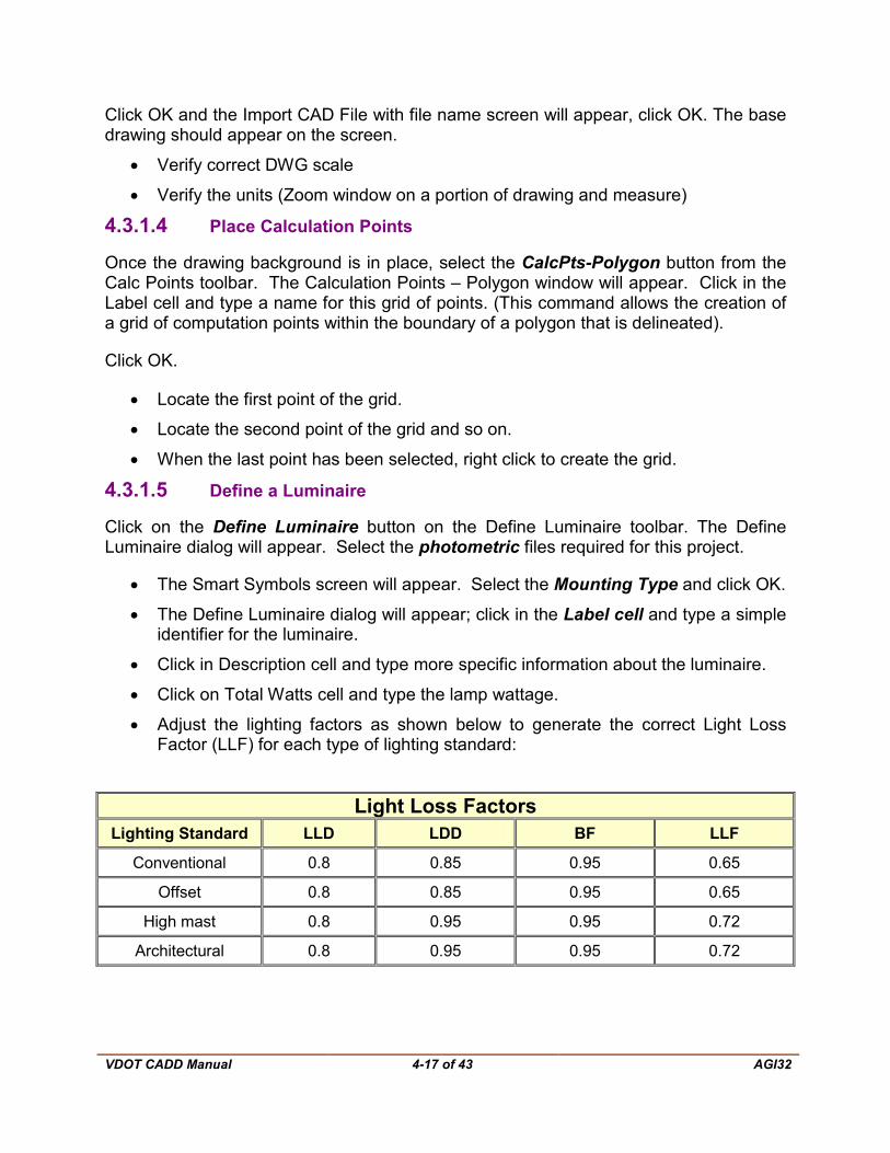
• Adjust the lighting factors as shown below to generate the correct Light Loss Factor (LLF) for each type of lighting standard:
Light Loss Factors Lighting Standard LLD LDD BF LLF
Conventional 0.8 0.85 0.95 0.65
Offset 0.8 0.85 0.95 0.65
High mast 0.8 0.95 0.95 0.72
Architectural 0.8 0.95 0.95 0.72

VDOT CADD Manual
4-18 of 43 AGI32
• Click in the Arrangement cell and select the Arrangement type.
• Click in the Arm Length cell and type the Arm length.
• Click on the Add/Redefine button on the right side of the dialog and then close the window.
• Click on the MH cell on the Lum Define toolbar and type Mounting Height.
• Click on the Orient cell and type the Orientation Angle.
• Click on the Tilt cell and type the Tilt Angle.
4.3.1.6 Locate the Luminaires
Once the luminaires are defined, they can be located on the drawing. Click on the Add Luminaire Location button on the Luminaire toolbar. The Luminaire symbol will be attached to the cursor and the user will be able to place the luminaries interactively on the drawing.
• First click positions the pole.
• Second click determines the orientation. Each subsequent click of the left mouse button will locate a luminaire on the drawing. Once all the luminaires are located, click the right mouse button to terminate the command.
4.3.1.7 Lighting Calculations
Click on the Calculate Now button on the toolbar (the calculator icon) to commence processing; results will then be displayed.
4.3.1.8 Export File
In order to export the file from AGI32 to MicroStation, Select File – Export and the Export File window will appear. The user must navigate to the appropriate directory and name the file then click OK.
• The Export DXF file dialog will appear; Select a scaling factor and then click OK.
4.3.1.9 Import the AGI32 file into MicroStation
In order to import the AGI32 file into MicroStation, the user must open MicroStation V8. Select File – Open and navigate to the appropriate directory, select ‘CAD Files’ under ‘List Files of Type’, then select the file and click OK.
Place the appropriate lighting symbol according to the lighting legend on the top of AGI luminaire locations and then remove the AGI Export file from the lighting plans
.

VDOT CADD Manual
4-19 of 43 AGI32
4.3.1.10 Create Roadway Lighting Layout
Create a lighting layout drawing showing the pole locations, conduit runs, junction boxes, power source locations and label all conduit runs and all symbols.

VDOT CADD Manual
4-20 of 43 TED Level Structure
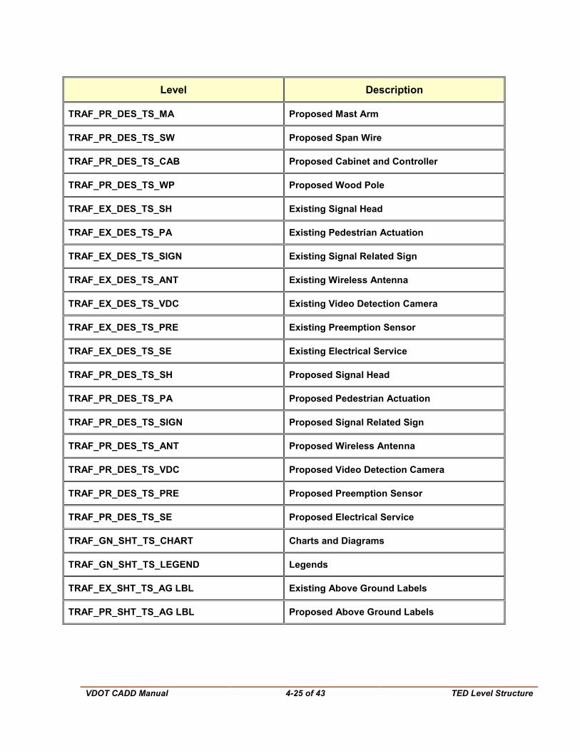
4.4 TED Level Structure
NOTE: All elements’ style, weight and color shall be set to ByLevel unless otherwise noted.
Level Description
Traffic – General
TRAF_GN_SHT_ALL_NAME Name in Top Right of Border
TRAF_GN_SHT_ALL_TITLE Title Block in bottom right of sheet
TRAF_GN_SHT_ALL_CTY City / County Label
TRAF_GN_SHT_ALL_LOGO_CON Consultant Logo
TRAF_GN_SHT_ALL_LOGO_COTED VDOT TED Logo
TRAF_GN_SHT_ALL_LOGO_OTHER Other Logo
TRAF_GN_SHT_ALL_MISC Miscellaneous Items
TRAF_GN_SHT_ALL_MS Milestone Stamps
TRAF_GN_DES_ALL_SNAP_DESC Design File - Description of Snap Points
TRAF_GN_DES_ALL_SNAP_PT Design File - Snap Points
TRAF_GN_SHT_ALL_SNAP_DESC Sheet File - Description of Snap Points
TRAF_GN_SHT_ALL_SNAP_PT Sheet File - Snap Points
TRAF_GN_SHT_SHT1_IOS Index of Sheets
TRAF_GN_SHT_SHT1_GNOTE General Notes
TRAF_GN_SHT_PS_DA Directional Arrows
TRAF_GN_SHT_PS_DIM Dimensions
TRAF_GN_SHT_PS_PN Plan Notes
TRAF_GN_SHT_PS_ROAD Roadway Names

VDOT CADD Manual
4-21 of 43 TED Level Structure
Level Description
TRAF_GN_SHT_PS_RW LABEL Proposed R/W Labels and Leaders for TCD Equipment
Traffic – Summary of Quantities
TRAF_GN_SHT_SQ_TABLE Table
TRAF_GN_SHT_SQ_INFO Information
TRAF_GN_SHT_SQ_MISC Miscellaneous
Pavement Marking
TRAF_EX_DES_PM_ARR Existing Arrows
TRAF_EX_DES_PM_HATCH Existing Hatching
TRAF_EX_DES_PM_LINE Existing Longitudinal
TRAF_EX_DES_PM_MARK Existing Pavement Markers
TRAF_EX_DES_PM_MSG Existing Message Markings
TRAF_EX_DES_PM_SYM Existing Symbols, Text and Route Shields
TRAF_EX_DES_PM_TRANS Existing Transverse (Stop Bars and Crosswalks)
TRAF_PR_DES_PM_ARR Proposed Arrows
TRAF_PR_DES_PM_HATCH Proposed Hatching
TRAF_PR_DES_PM_LINE Proposed Longitudinal
TRAF_PR_DES_PM_MARK Proposed Pavement Markers
TRAF_PR_DES_PM_MSG Proposed Message Markings
TRAF_PR_DES_PM_SYM Proposed Symbols, Text and Route Shields
TRAF_PR_DES_PM_TRANS Proposed Transverse (Stop Bars and Crosswalks)
VDOT CADD Manual
4-22 of 43 TED Level Structure
Level Description
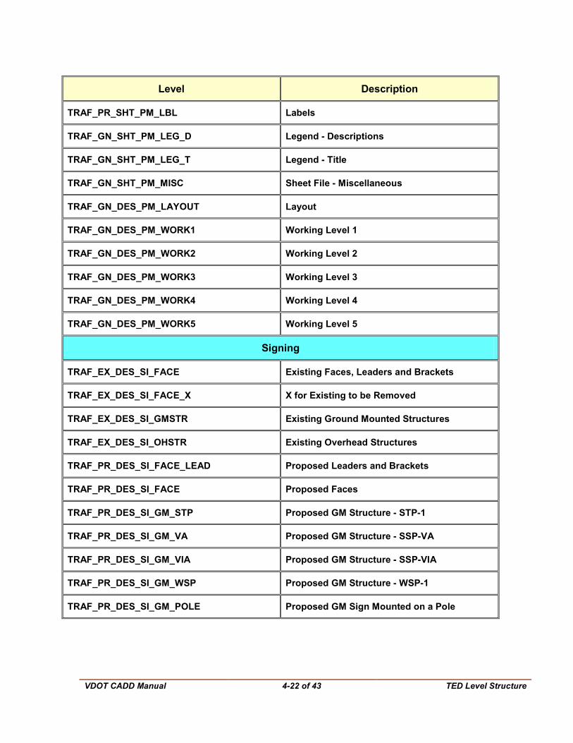
TRAF_PR_SHT_PM_LBL Labels
TRAF_GN_SHT_PM_LEG_D Legend - Descriptions
TRAF_GN_SHT_PM_LEG_T Legend - Title
TRAF_GN_SHT_PM_MISC Sheet File - Miscellaneous
TRAF_GN_DES_PM_LAYOUT Layout
TRAF_GN_DES_PM_WORK1 Working Level 1
TRAF_GN_DES_PM_WORK2 Working Level 2
TRAF_GN_DES_PM_WORK3 Working Level 3
TRAF_GN_DES_PM_WORK4 Working Level 4
TRAF_GN_DES_PM_WORK5 Working Level 5
Signing
TRAF_EX_DES_SI_FACE Existing Faces, Leaders and Brackets
TRAF_EX_DES_SI_FACE_X X for Existing to be Removed
TRAF_EX_DES_SI_GMSTR Existing Ground Mounted Structures
TRAF_EX_DES_SI_OHSTR Existing Overhead Structures
TRAF_PR_DES_SI_FACE_LEAD Proposed Leaders and Brackets
TRAF_PR_DES_SI_FACE Proposed Faces
TRAF_PR_DES_SI_GM_STP Proposed GM Structure - STP-1
TRAF_PR_DES_SI_GM_VA Proposed GM Structure - SSP-VA
TRAF_PR_DES_SI_GM_VIA Proposed GM Structure - SSP-VIA
TRAF_PR_DES_SI_GM_WSP Proposed GM Structure - WSP-1
TRAF_PR_DES_SI_GM_POLE Proposed GM Sign Mounted on a Pole
VDOT CADD Manual
4-23 of 43 TED Level Structure
Level Description
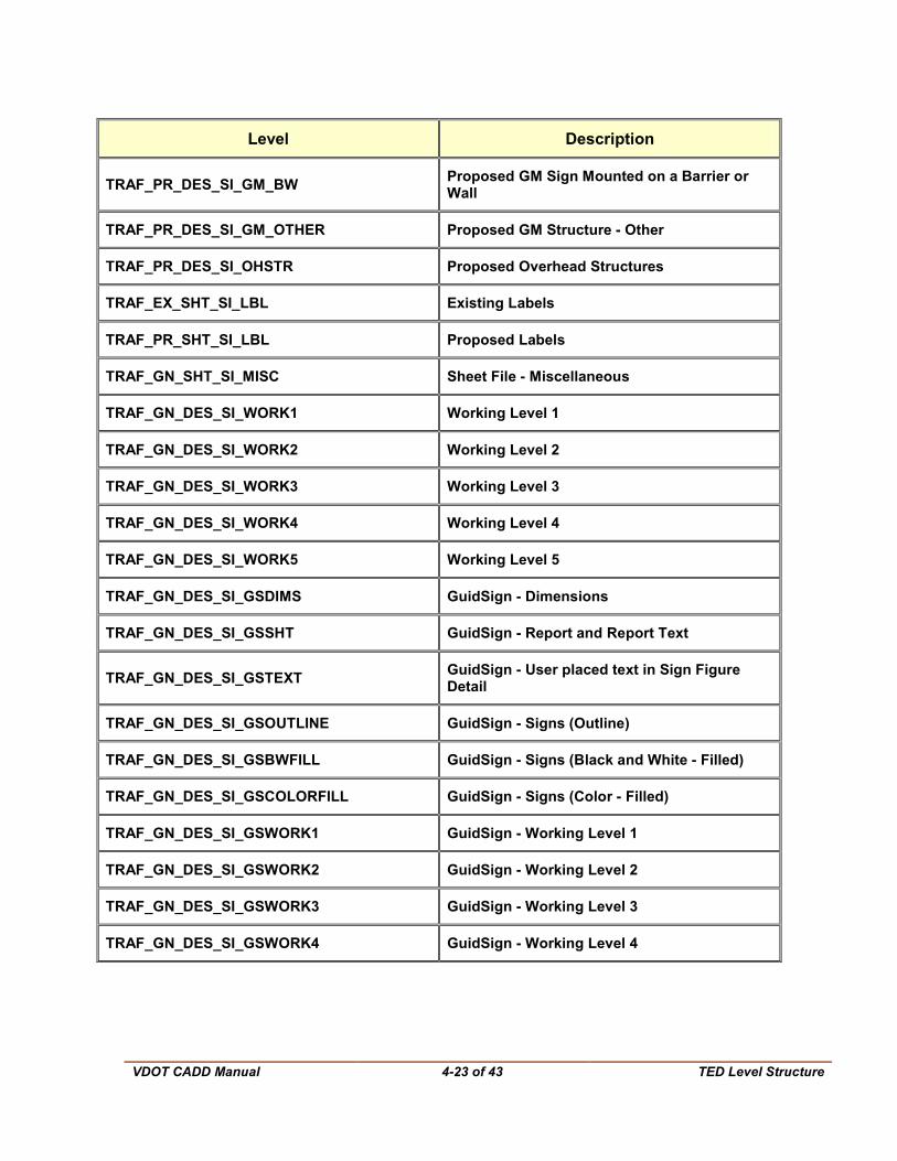
TRAF_PR_DES_SI_GM_BW Proposed GM Sign Mounted on a Barrier or Wall
TRAF_PR_DES_SI_GM_OTHER Proposed GM Structure - Other
TRAF_PR_DES_SI_OHSTR Proposed Overhead Structures
TRAF_EX_SHT_SI_LBL Existing Labels
TRAF_PR_SHT_SI_LBL Proposed Labels
TRAF_GN_SHT_SI_MISC Sheet File - Miscellaneous
TRAF_GN_DES_SI_WORK1 Working Level 1
TRAF_GN_DES_SI_WORK2 Working Level 2
TRAF_GN_DES_SI_WORK3 Working Level 3
TRAF_GN_DES_SI_WORK4 Working Level 4
TRAF_GN_DES_SI_WORK5 Working Level 5
TRAF_GN_DES_SI_GSDIMS GuidSign - Dimensions
TRAF_GN_DES_SI_GSSHT GuidSign - Report and Report Text
TRAF_GN_DES_SI_GSTEXT GuidSign - User placed text in Sign Figure Detail
TRAF_GN_DES_SI_GSOUTLINE GuidSign - Signs (Outline)
TRAF_GN_DES_SI_GSBWFILL GuidSign - Signs (Black and White - Filled)
TRAF_GN_DES_SI_GSCOLORFILL GuidSign - Signs (Color - Filled)
TRAF_GN_DES_SI_GSWORK1 GuidSign - Working Level 1
TRAF_GN_DES_SI_GSWORK2 GuidSign - Working Level 2
TRAF_GN_DES_SI_GSWORK3 GuidSign - Working Level 3
TRAF_GN_DES_SI_GSWORK4 GuidSign - Working Level 4
VDOT CADD Manual
4-24 of 43 TED Level Structure
Level Description
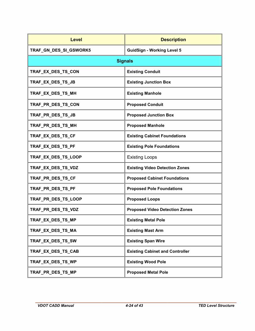
TRAF_GN_DES_SI_GSWORK5 GuidSign - Working Level 5
Signals
TRAF_EX_DES_TS_CON Existing Conduit
TRAF_EX_DES_TS_JB Existing Junction Box
TRAF_EX_DES_TS_MH Existing Manhole
TRAF_PR_DES_TS_CON Proposed Conduit
TRAF_PR_DES_TS_JB Proposed Junction Box
TRAF_PR_DES_TS_MH Proposed Manhole
TRAF_EX_DES_TS_CF Existing Cabinet Foundations
TRAF_EX_DES_TS_PF Existing Pole Foundations
TRAF_EX_DES_TS_LOOP Existing Loops
TRAF_EX_DES_TS_VDZ Existing Video Detection Zones
TRAF_PR_DES_TS_CF Proposed Cabinet Foundations
TRAF_PR_DES_TS_PF Proposed Pole Foundations
TRAF_PR_DES_TS_LOOP Proposed Loops
TRAF_PR_DES_TS_VDZ Proposed Video Detection Zones
TRAF_EX_DES_TS_MP Existing Metal Pole
TRAF_EX_DES_TS_MA Existing Mast Arm
TRAF_EX_DES_TS_SW Existing Span Wire
TRAF_EX_DES_TS_CAB Existing Cabinet and Controller
TRAF_EX_DES_TS_WP Existing Wood Pole
TRAF_PR_DES_TS_MP Proposed Metal Pole
VDOT CADD Manual
4-25 of 43 TED Level Structure
Level Description
TRAF_PR_DES_TS_MA Proposed Mast Arm
TRAF_PR_DES_TS_SW Proposed Span Wire
TRAF_PR_DES_TS_CAB Proposed Cabinet and Controller
TRAF_PR_DES_TS_WP Proposed Wood Pole
TRAF_EX_DES_TS_SH Existing Signal Head
TRAF_EX_DES_TS_PA Existing Pedestrian Actuation
TRAF_EX_DES_TS_SIGN Existing Signal Related Sign
TRAF_EX_DES_TS_ANT Existing Wireless Antenna
TRAF_EX_DES_TS_VDC Existing Video Detection Camera
TRAF_EX_DES_TS_PRE Existing Preemption Sensor
TRAF_EX_DES_TS_SE Existing Electrical Service
TRAF_PR_DES_TS_SH Proposed Signal Head
TRAF_PR_DES_TS_PA Proposed Pedestrian Actuation
TRAF_PR_DES_TS_SIGN Proposed Signal Related Sign
TRAF_PR_DES_TS_ANT Proposed Wireless Antenna
TRAF_PR_DES_TS_VDC Proposed Video Detection Camera
TRAF_PR_DES_TS_PRE Proposed Preemption Sensor
TRAF_PR_DES_TS_SE Proposed Electrical Service
TRAF_GN_SHT_TS_CHART Charts and Diagrams
TRAF_GN_SHT_TS_LEGEND Legends
TRAF_EX_SHT_TS_AG LBL Existing Above Ground Labels
TRAF_PR_SHT_TS_AG LBL Proposed Above Ground Labels
VDOT CADD Manual
4-26 of 43 TED Level Structure
Level Description
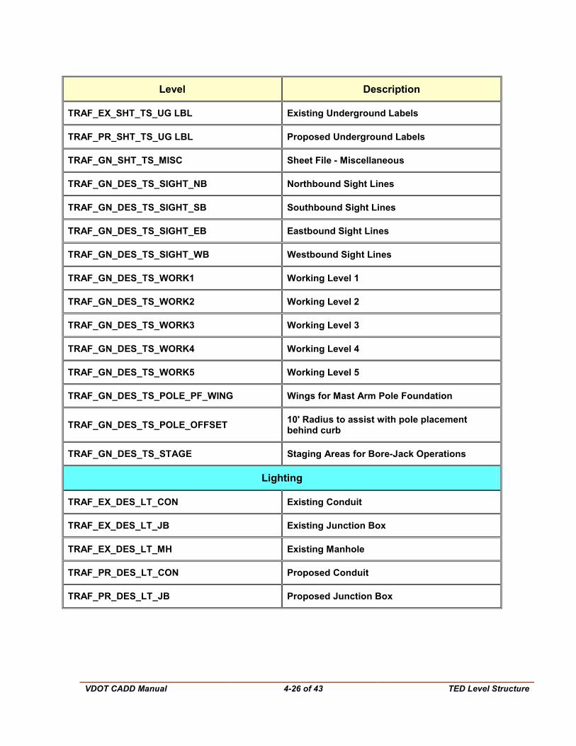
TRAF_EX_SHT_TS_UG LBL Existing Underground Labels
TRAF_PR_SHT_TS_UG LBL Proposed Underground Labels
TRAF_GN_SHT_TS_MISC Sheet File - Miscellaneous
TRAF_GN_DES_TS_SIGHT_NB Northbound Sight Lines
TRAF_GN_DES_TS_SIGHT_SB Southbound Sight Lines
TRAF_GN_DES_TS_SIGHT_EB Eastbound Sight Lines
TRAF_GN_DES_TS_SIGHT_WB Westbound Sight Lines
TRAF_GN_DES_TS_WORK1 Working Level 1
TRAF_GN_DES_TS_WORK2 Working Level 2
TRAF_GN_DES_TS_WORK3 Working Level 3
TRAF_GN_DES_TS_WORK4 Working Level 4
TRAF_GN_DES_TS_WORK5 Working Level 5
TRAF_GN_DES_TS_POLE_PF_WING Wings for Mast Arm Pole Foundation
TRAF_GN_DES_TS_POLE_OFFSET 10' Radius to assist with pole placement behind curb
TRAF_GN_DES_TS_STAGE Staging Areas for Bore-Jack Operations
Lighting
TRAF_EX_DES_LT_CON Existing Conduit
TRAF_EX_DES_LT_JB Existing Junction Box
TRAF_EX_DES_LT_MH Existing Manhole
TRAF_PR_DES_LT_CON Proposed Conduit
TRAF_PR_DES_LT_JB Proposed Junction Box
VDOT CADD Manual
4-27 of 43 TED Level Structure
Level Description
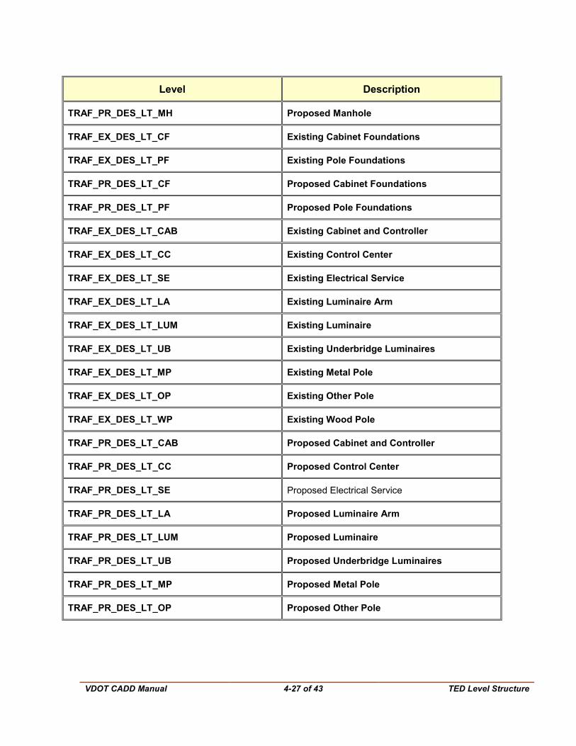
TRAF_PR_DES_LT_MH Proposed Manhole
TRAF_EX_DES_LT_CF Existing Cabinet Foundations
TRAF_EX_DES_LT_PF Existing Pole Foundations
TRAF_PR_DES_LT_CF Proposed Cabinet Foundations
TRAF_PR_DES_LT_PF Proposed Pole Foundations
TRAF_EX_DES_LT_CAB Existing Cabinet and Controller
TRAF_EX_DES_LT_CC Existing Control Center
TRAF_EX_DES_LT_SE Existing Electrical Service
TRAF_EX_DES_LT_LA Existing Luminaire Arm
TRAF_EX_DES_LT_LUM Existing Luminaire
TRAF_EX_DES_LT_UB Existing Underbridge Luminaires
TRAF_EX_DES_LT_MP Existing Metal Pole
TRAF_EX_DES_LT_OP Existing Other Pole
TRAF_EX_DES_LT_WP Existing Wood Pole
TRAF_PR_DES_LT_CAB Proposed Cabinet and Controller
TRAF_PR_DES_LT_CC Proposed Control Center
TRAF_PR_DES_LT_SE Proposed Electrical Service
TRAF_PR_DES_LT_LA Proposed Luminaire Arm
TRAF_PR_DES_LT_LUM Proposed Luminaire
TRAF_PR_DES_LT_UB Proposed Underbridge Luminaires
TRAF_PR_DES_LT_MP Proposed Metal Pole
TRAF_PR_DES_LT_OP Proposed Other Pole
VDOT CADD Manual
4-28 of 43 TED Level Structure
Level Description
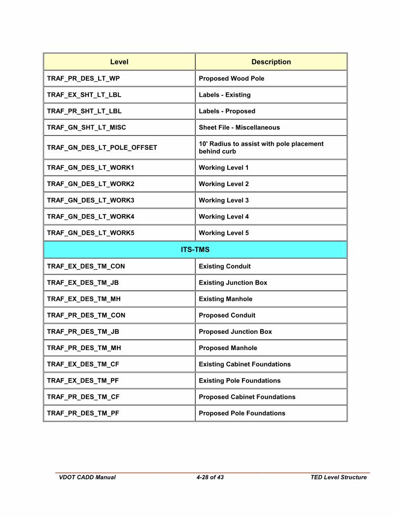
TRAF_PR_DES_LT_WP Proposed Wood Pole
TRAF_EX_SHT_LT_LBL Labels - Existing
TRAF_PR_SHT_LT_LBL Labels - Proposed
TRAF_GN_SHT_LT_MISC Sheet File - Miscellaneous
TRAF_GN_DES_LT_POLE_OFFSET 10' Radius to assist with pole placement behind curb
TRAF_GN_DES_LT_WORK1 Working Level 1
TRAF_GN_DES_LT_WORK2 Working Level 2
TRAF_GN_DES_LT_WORK3 Working Level 3
TRAF_GN_DES_LT_WORK4 Working Level 4
TRAF_GN_DES_LT_WORK5 Working Level 5
ITS-TMS
TRAF_EX_DES_TM_CON Existing Conduit
TRAF_EX_DES_TM_JB Existing Junction Box
TRAF_EX_DES_TM_MH Existing Manhole
TRAF_PR_DES_TM_CON Proposed Conduit
TRAF_PR_DES_TM_JB Proposed Junction Box
TRAF_PR_DES_TM_MH Proposed Manhole
TRAF_EX_DES_TM_CF Existing Cabinet Foundations
TRAF_EX_DES_TM_PF Existing Pole Foundations
TRAF_PR_DES_TM_CF Proposed Cabinet Foundations
TRAF_PR_DES_TM_PF Proposed Pole Foundations

VDOT CADD Manual
4-29 of 43 TED Level Structure
Level Description
TRAF_EX_DES_TM_CAB Existing Cabinet and Controller
TRAF_EX_DES_TM_SE Existing Electrical Service
TRAF_EX_DES_TM_CAM Existing CCTV Camera
TRAF_EX_DES_TM_DMS Existing Dynamic Message Sign
TRAF_EX_DES_TM_HAR Existing Highway Advisory Radio
TRAF_EX_DES_TM_RTMS Existing Traffic Sensor
TRAF_EX_DES_TM_RWIS Existing Weather Information Station
TRAF_EX_DES_TM_MP Existing Metal Pole
TRAF_EX_DES_TM_OP Existing Other Pole
TRAF_EX_DES_TM_WP Existing Wood Pole
TRAF_PR_DES_TM_CAB Proposed Cabinet and Controller
TRAF_PR_DES_TM_SE Proposed Electrical Service
TRAF_PR_DES_TM_CAM Proposed CCTV Camera
TRAF_PR_DES_TM_DMS Proposed Dynamic Message Sign
TRAF_PR_DES_TM_HAR Proposed Highway Advisory Radio
TRAF_PR_DES_TM_RTMS Proposed Traffic Sensor
TRAF_PR_DES_TM_RWIS Proposed Weather Information Station
TRAF_PR_DES_TM_MP Proposed Metal Pole
TRAF_PR_DES_TM_OP Proposed Other Pole
TRAF_PR_DES_TM_WP Proposed Wood Pole
TRAF_EX_SHT_TM_AG LBL Existing Above Ground Labels
TRAF_PR_SHT_TM_AG LBL Proposed Above Ground Labels

VDOT CADD Manual
4-30 of 43 TED Level Structure
Level Description
TRAF_EX_SHT_TM_UG LBL Existing Underground Labels
TRAF_PR_SHT_TM_UG LBL Proposed Underground Labels
TRAF_GN_SHT_TM_MISC Sheet File - Miscellaneous
TRAF_GN_DES_TM_WORK1 Working Level 1
TRAF_GN_DES_TM_WORK2 Working Level 2
TRAF_GN_DES_TM_WORK3 Working Level 3
TRAF_GN_DES_TM_WORK4 Working Level 4
TRAF_GN_DES_TM_WORK5 Working Level 5
Multi-Line Settings for Conduit Offset Color Style Weight
0.8 34 3 3
0 34 0 3
-0.8 34 3 3 Note - Under the 'End Caps and Joints' tab the line column should be unchecked for 'Start Cap', 'End Cap' & 'Joints'

VDOT CADD Manual
4-31 of 43 TED Design Guidelines
4.5 TED Design Guidelines
4.5.1 Text Font and Size
VDOT TCD plans use a combination of ‘Engineering’ (MicroStation Font 3) and ‘Italics’ (MicroStation Font 23) fonts. Text sizes are based on the drawing scale. Generally, the minimum text size for TCD plans is 1/8”. The MicroStation text size for scales may be computed by dividing the drawing scale by 8. For example: A 25 Scale drawing should have a minimum text size of 3.125. 25/8 = 3.125 Title text on TCD plans should be approximately 3/16”. Again, the MicroStation title text size for scales may be computed by multiplying the drawing scale by 3 and divide by 16. A majority of text notes, legends, and call-outs are included in the TED cell libraries. The text size in the cell libraries is based on 25 scale plans. If a different scale is required then the cell should be scaled using the following formula:
Plan Sheet Scale / 25 = Scale Factor
4.5.2 Cell Libraries
The following instructions are used to demonstrate the purpose and uses of the cell library for the Traffic Section of the Location and Design Division.
4.5.2.1 Overview
The Traffic Engineering section of the Location and Design Division generally utilizes TED cell libraries for the completion of TCD plans using MicroStation.
The cell library provides Imperial cells only. The cell library also gives descriptive details about the cells such as the name of the cell, the cell description, and the cell library shows an image of the given cell.
VDOT CADD Manual
4-32 of 43 TED Design Guidelines
4.5.3 Traffic Cell Libraries
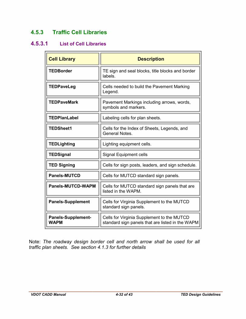
4.5.3.1 List of Cell Libraries
Cell Library Description
TEDBorder TE sign and seal blocks, title blocks and border labels.
TEDPaveLeg Cells needed to build the Pavement Marking Legend.
TEDPaveMark Pavement Markings including arrows, words, symbols and markers.
TEDPlanLabel Labeling cells for plan sheets.
TEDSheet1 Cells for the Index of Sheets, Legends, and General Notes.
TEDLighting Lighting equipment cells.
TEDSignal Signal Equipment cells
TED Signing Cells for sign posts, leaders, and sign schedule.
Panels-MUTCD Cells for MUTCD standard sign panels.
Panels-MUTCD-WAPM Cells for MUTCD standard sign panels that are listed in the WAPM.
Panels-Supplement Cells for Virginia Supplement to the MUTCD standard sign panels.
Panels-Supplement-WAPM
Cells for Virginia Supplement to the MUTCD standard sign panels that are listed in the WAPM
Note: The roadway design border cell and north arrow shall be used for all traffic plan sheets. See section 4.1.3 for further details

VDOT CADD Manual
4-33 of 43 TED Design Guidelines
This cell library window in MicroStation is show below.
4.5.3.2 MicroStation Access
To access the cell library through MicroStation:
• Select the MicroStation Icon
• Select Element at the top of the screen/task bar
• Select Cells
- a cell library window will appear –
• Select File from the Cell library window (a list of cells will appear in a drop down menu)
• Click on the cell library from the drop down menu of your choice such as TEDSigning.cel, TEDSignal.cel, etc.
• Scroll through the cell library window until the user finds the appropriate cell.
• Double click the cell and place the cell in the design file.

VDOT CADD Manual
4-34 of 43 TED Design Guidelines
4.5.3.3 Adjusting the size of the cell
Most of the design cells in the cell library are drawn to scale. If the cell appears to be too small or too large when placing it, refer to the following instructions on cell adjustment:
• When the user double clicks the cell, a ‘Place Active Cell’ window appears.
• Data into the X Scale of the Place Active Cell window and type in the scale to decrease the cell or to increase the cell, then press the ‘Enter’ key. Pressing ‘Enter’ after typing in the X Scale will automatically change the Y Scale to the same number.
• This will now adjust the size of the cell. Place the cell into the design file by left clicking.
• Sign Panel cells are designed to be placed using the scale of the plan sheet (ie. 25 or 50). Very large or small signs, and custom signs will still need to be adjusted.
4.5.3.4 Signal Pole & Controller Cabinet Legend Cells
A number of cells are available in the TEDPlanLabel.cel cell library that can be utilized to develop signal pole and controller cabinet legends. The signal pole legend cells have been designed to give the user the flexibility to build multiple signal pole or controller cabinet legends. All cells, except those for the electrical service and the wireless antenna, utilize ‘tags’ that allow for easy data entry for the variable attributes included in each line of the legend. See section 4.5.2.5.3 for tag editing procedures.
Modifications to the electrical service cell should be made using the “Edit Text” command. Typically, there should be no modifications needed for the wireless antenna cell.
4.5.2.5.1 Creating Legends
To create a signal pole or controller cabinet legend, place the cell containing the first line of the legend:
LGD POLE_LBL for mast arms and strain poles; LGD PED_LBL for pedestal poles; or LGD CONT for controller cabinets
Next, edit the variable text in that cell using the ‘Edit Tags’ command (see section 4.5.2.5.2). Then, place cells containing the remaining lines until a complete legend is created for the pole. The ‘LGD POLE_LBL’ and ‘LGD PED_LBL’ cells contain snap points (located on MicroStation level 62) for snapping subsequent lines of the legend obtained from other cells. The snap points are provided for uniform text alignment. (Note that there are no subsequent lines of legend to be added for controller cabinet legends)
VDOT CADD Manual
4-35 of 43 TED Design Guidelines
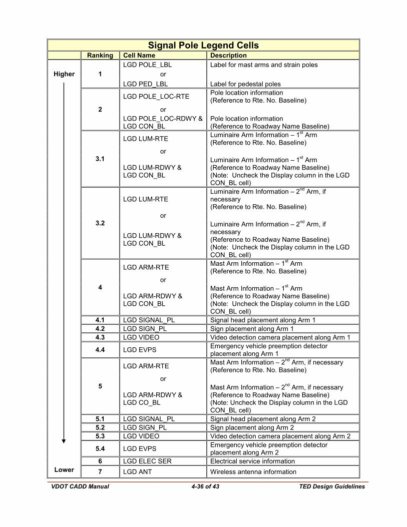
The available signal pole legend cells are shown in the table on the following page. The higher ranked cells should be placed over lower ranked cells.
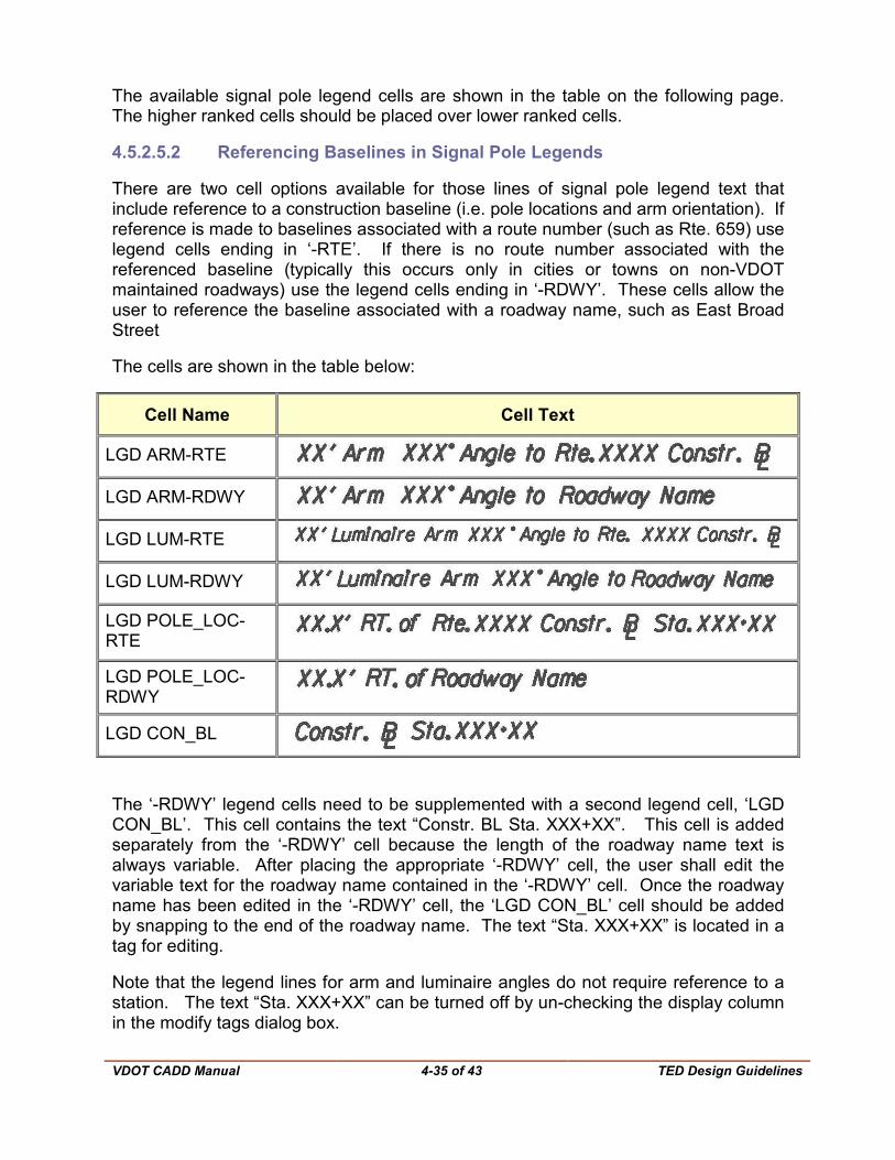
4.5.2.5.2 Referencing Baselines in Signal Pole Legends
There are two cell options available for those lines of signal pole legend text that include reference to a construction baseline (i.e. pole locations and arm orientation). If reference is made to baselines associated with a route number (such as Rte. 659) use legend cells ending in ‘-RTE’. If there is no route number associated with the referenced baseline (typically this occurs only in cities or towns on non-VDOT maintained roadways) use the legend cells ending in ‘-RDWY’. These cells allow the user to reference the baseline associated with a roadway name, such as East Broad Street
The cells are shown in the table below:
Cell Name Cell Text
LGD ARM-RTE
LGD ARM-RDWY
LGD LUM-RTE
LGD LUM-RDWY
LGD POLE_LOC-RTE
LGD POLE_LOC-RDWY
LGD CON_BL
The ‘-RDWY’ legend cells need to be supplemented with a second legend cell, ‘LGD CON_BL’. This cell contains the text “Constr. BL Sta. XXX+XX”. This cell is added separately from the ‘-RDWY’ cell because the length of the roadway name text is always variable. After placing the appropriate ‘-RDWY’ cell, the user shall edit the variable text for the roadway name contained in the ‘-RDWY’ cell. Once the roadway name has been edited in the ‘-RDWY’ cell, the ‘LGD CON_BL’ cell should be added by snapping to the end of the roadway name. The text “Sta. XXX+XX” is located in a tag for editing.
Note that the legend lines for arm and luminaire angles do not require reference to a station. The text “Sta. XXX+XX” can be turned off by un-checking the display column in the modify tags dialog box.
VDOT CADD Manual
4-36 of 43 TED Design Guidelines
Signal Pole Legend Cells Ranking Cell Name Description
Higher 1 LGD POLE_LBL Label for mast arms and strain poles
or LGD PED_LBL Label for pedestal poles
2
LGD POLE_LOC-RTE Pole location information (Reference to Rte. No. Baseline)
or LGD POLE_LOC-RDWY & LGD CON_BL
Pole location information (Reference to Roadway Name Baseline)
3.1
LGD LUM-RTE Luminaire Arm Information – 1st Arm (Reference to Rte. No. Baseline)
or
LGD LUM-RDWY & LGD CON_BL
Luminaire Arm Information – 1st Arm (Reference to Roadway Name Baseline) (Note: Uncheck the Display column in the LGD CON_BL cell)
3.2
LGD LUM-RTE Luminaire Arm Information – 2nd Arm, if necessary (Reference to Rte. No. Baseline)
or
LGD LUM-RDWY & LGD CON_BL
Luminaire Arm Information – 2nd Arm, if necessary (Reference to Roadway Name Baseline) (Note: Uncheck the Display column in the LGD CON_BL cell)
4
LGD ARM-RTE Mast Arm Information – 1st Arm (Reference to Rte. No. Baseline)
or
LGD ARM-RDWY & LGD CON_BL
Mast Arm Information – 1st Arm (Reference to Roadway Name Baseline) (Note: Uncheck the Display column in the LGD CON_BL cell)
4.1 LGD SIGNAL_PL Signal head placement along Arm 1 4.2 LGD SIGN_PL Sign placement along Arm 1 4.3 LGD VIDEO Video detection camera placement along Arm 1
4.4 LGD EVPS Emergency vehicle preemption detector placement along Arm 1
5
LGD ARM-RTE Mast Arm Information – 2nd Arm, if necessary (Reference to Rte. No. Baseline)
or
LGD ARM-RDWY & LGD CO_BL
Mast Arm Information – 2nd Arm, if necessary (Reference to Roadway Name Baseline) (Note: Uncheck the Display column in the LGD CON_BL cell)
5.1 LGD SIGNAL_PL Signal head placement along Arm 2 5.2 LGD SIGN_PL Sign placement along Arm 2 5.3 LGD VIDEO Video detection camera placement along Arm 2
5.4 LGD EVPS Emergency vehicle preemption detector placement along Arm 2
6 LGD ELEC SER Electrical service information Lower 7 LGD ANT Wireless antenna information
VDOT CADD Manual
4-37 of 43 TED Design Guidelines
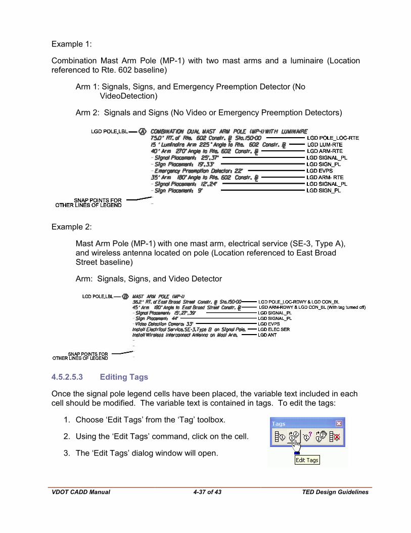
Example 1:
Combination Mast Arm Pole (MP-1) with two mast arms and a luminaire (Location referenced to Rte. 602 baseline)
Arm 1: Signals, Signs, and Emergency Preemption Detector (No VideoDetection)
Arm 2: Signals and Signs (No Video or Emergency Preemption Detectors)
Example 2:
Mast Arm Pole (MP-1) with one mast arm, electrical service (SE-3, Type A), and wireless antenna located on pole (Location referenced to East Broad Street baseline)
Arm: Signals, Signs, and Video Detector
4.5.2.5.3 Editing Tags
Once the signal pole legend cells have been placed, the variable text included in each cell should be modified. The variable text is contained in tags. To edit the tags:
1. Choose ‘Edit Tags’ from the ‘Tag’ toolbox.
2. Using the ‘Edit Tags’ command, click on the cell.
3. The ‘Edit Tags’ dialog window will open.

VDOT CADD Manual
4-38 of 43 TED Design Guidelines
4. The box will list all variable text included in the cell. Edit any variable text in the ‘Value’ column. Holding the cursor over any text in the ‘Value’ column displays a prompt that describes the information that should be input in each line.
5. Click OK and the cell is automatically updated to incorporate the text input in step 4. All text is incorporated into the cell at the correct justifications. Depending on the entered text there may be extra spaces between some text elements. This is acceptable. Do not ‘Drop Status’ on the cell because the functionality of the tag will be lost.
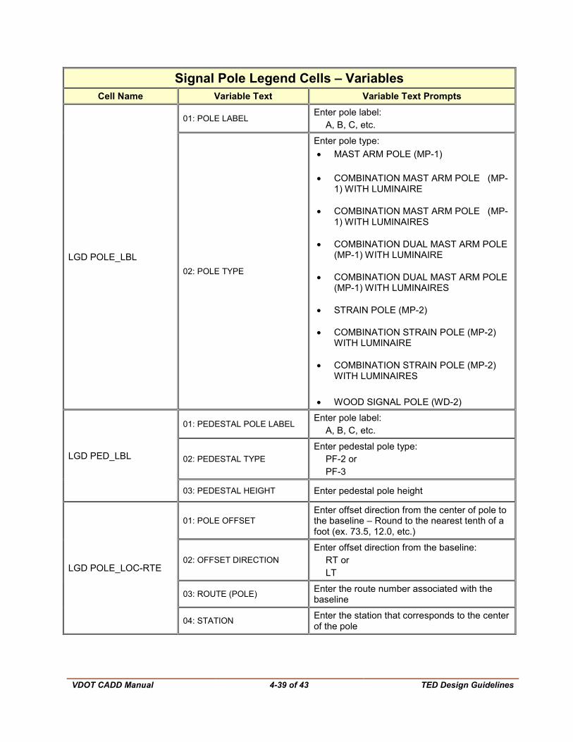
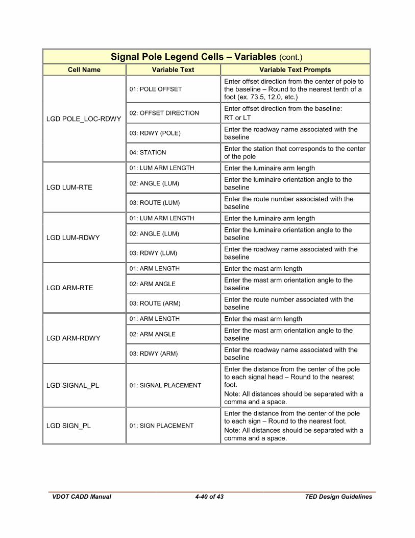
The table on the following page displays the signal pole legend cells included in the TEDPlanLabel.cel cell library and the variable text included in each cell.
VDOT CADD Manual
4-39 of 43 TED Design Guidelines
Signal Pole Legend Cells – Variables Cell Name Variable Text Variable Text Prompts
LGD POLE_LBL
01: POLE LABEL Enter pole label:
A, B, C, etc.
02: POLE TYPE
Enter pole type: • MAST ARM POLE (MP-1) • COMBINATION MAST ARM POLE (MP-
1) WITH LUMINAIRE • COMBINATION MAST ARM POLE (MP-
1) WITH LUMINAIRES • COMBINATION DUAL MAST ARM POLE
(MP-1) WITH LUMINAIRE • COMBINATION DUAL MAST ARM POLE
(MP-1) WITH LUMINAIRES • STRAIN POLE (MP-2)
• COMBINATION STRAIN POLE (MP-2)
WITH LUMINAIRE • COMBINATION STRAIN POLE (MP-2)
WITH LUMINAIRES • WOOD SIGNAL POLE (WD-2)
LGD PED_LBL
01: PEDESTAL POLE LABEL Enter pole label:
A, B, C, etc.
02: PEDESTAL TYPE Enter pedestal pole type:
PF-2 or PF-3
03: PEDESTAL HEIGHT Enter pedestal pole height
LGD POLE_LOC-RTE
01: POLE OFFSET Enter offset direction from the center of pole to the baseline – Round to the nearest tenth of a foot (ex. 73.5, 12.0, etc.)
02: OFFSET DIRECTION Enter offset direction from the baseline:
RT or LT
03: ROUTE (POLE) Enter the route number associated with the baseline
04: STATION Enter the station that corresponds to the center of the pole
VDOT CADD Manual
4-40 of 43 TED Design Guidelines
Signal Pole Legend Cells – Variables (cont.) Cell Name Variable Text Variable Text Prompts
LGD POLE_LOC-RDWY
01: POLE OFFSET Enter offset direction from the center of pole to the baseline – Round to the nearest tenth of a foot (ex. 73.5, 12.0, etc.)
02: OFFSET DIRECTION Enter offset direction from the baseline: RT or LT
03: RDWY (POLE) Enter the roadway name associated with the baseline
04: STATION Enter the station that corresponds to the center of the pole
LGD LUM-RTE
01: LUM ARM LENGTH Enter the luminaire arm length
02: ANGLE (LUM) Enter the luminaire orientation angle to the baseline
03: ROUTE (LUM) Enter the route number associated with the baseline
LGD LUM-RDWY
01: LUM ARM LENGTH Enter the luminaire arm length
02: ANGLE (LUM) Enter the luminaire orientation angle to the baseline
03: RDWY (LUM) Enter the roadway name associated with the baseline
LGD ARM-RTE
01: ARM LENGTH Enter the mast arm length
02: ARM ANGLE Enter the mast arm orientation angle to the baseline
03: ROUTE (ARM) Enter the route number associated with the baseline
LGD ARM-RDWY
01: ARM LENGTH Enter the mast arm length
02: ARM ANGLE Enter the mast arm orientation angle to the baseline
03: RDWY (ARM) Enter the roadway name associated with the baseline
LGD SIGNAL_PL 01: SIGNAL PLACEMENT
Enter the distance from the center of the pole to each signal head – Round to the nearest foot. Note: All distances should be separated with a comma and a space.
LGD SIGN_PL 01: SIGN PLACEMENT
Enter the distance from the center of the pole to each sign – Round to the nearest foot. Note: All distances should be separated with a comma and a space.
VDOT CADD Manual
4-41 of 43 TED Design Guidelines
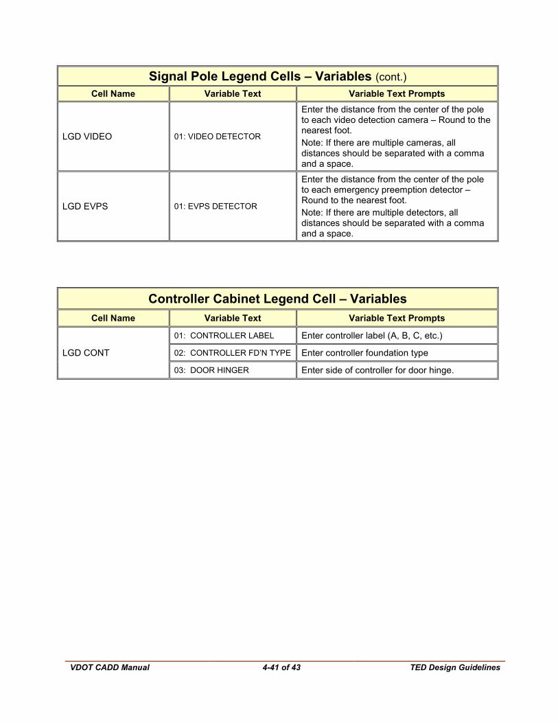
Signal Pole Legend Cells – Variables (cont.) Cell Name Variable Text Variable Text Prompts
LGD VIDEO 01: VIDEO DETECTOR
Enter the distance from the center of the pole to each video detection camera – Round to the nearest foot. Note: If there are multiple cameras, all distances should be separated with a comma and a space.
LGD EVPS 01: EVPS DETECTOR
Enter the distance from the center of the pole to each emergency preemption detector – Round to the nearest foot. Note: If there are multiple detectors, all distances should be separated with a comma and a space.
Controller Cabinet Legend Cell – Variables
Cell Name Variable Text Variable Text Prompts
LGD CONT
01: CONTROLLER LABEL Enter controller label (A, B, C, etc.)
02: CONTROLLER FD’N TYPE Enter controller foundation type
03: DOOR HINGER Enter side of controller for door hinge.
VDOT CADD Manual
4-42 of 43 TED Design Guidelines
4.6 Plotting with MicroStation V8i
For detailed information on plotting please click on this link Chapter 3, Section 3.11
For all TCD plans, users shall plot using the following pen tables:
For Full-size plots –ld_v95 traffic.tbl
For Half-size plots – half_v95 traffic.tbl