table of contents section 23 - leading distributor of ... · table of contents section 23 relays...
TRANSCRIPT
23-1© 2009 Schneider ElectricAll Rights Reserved
23R
ELA
YS
AN
D T
IME
RS
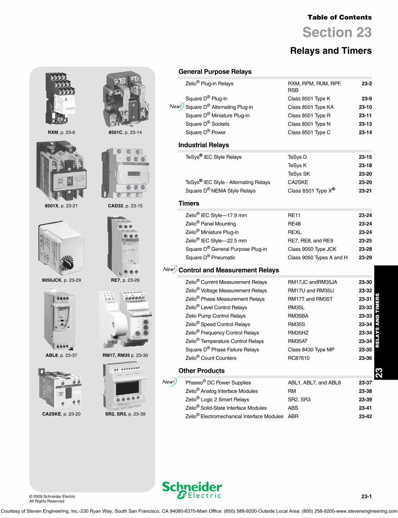
Table of Contents
Section 23Relays and Timers
RXM, p. 23-6 8501C, p. 23-14
8501X, p. 23-21 CAD32, p. 23-15
9050JCK, p. 23-29 RE7, p. 23-26
ABL8, p. 23-37 RM17, RM35 p. 23-30
CA2SKE, p. 23-20 SR2, SR3, p. 23-39
General Purpose Relays
Zelio® Plug-in Relays RXM, RPM, RUM, RPF, RSB
23-2
Square D® Plug-in Class 8501 Type K 23-9
Square D® Alternating Plug-in Class 8501 Type KA 23-10
Square D® Miniature Plug-in Class 8501 Type R 23-11
Square D® Sockets Class 8501 Type N 23-13
Square D® Power Class 8501 Type C 23-14
Industrial Relays
TeSys® IEC Style Relays TeSys D 23-15
TeSys K 23-18
TeSys SK 23-20
TeSys® IEC Style - Alternating Relays CA2SKE 23-20
Square D® NEMA Style Relays Class 8501 Type X® 23-21
Timers
Zelio® IEC Style—17.9 mm RE11 23-24
Zelio® Panel Mounting RE48 23-24
Zelio® Miniature Plug-in REXL 23-24
Zelio® IEC Style—22.5 mm RE7, RE8, and RE9 23-25
Square D® General Purpose Plug-in Class 9050 Type JCK 23-28
Square D® Pneumatic Class 9050 Types A and H 23-29
Control and Measurement Relays
Zelio® Current Measurement Relays RM17JC andRM35JA 23-30
Zelio® Voltage Measurement Relays RM17U and RM35U 23-32
Zelio® Phase Measurement Relays RM17T and RM35T 23-31
Zelio® Level Control Relays RM35L 23-33
Zelio Pump Control Relays RM35BA 23-33
Zelio® Speed Control Relays RM35S 23-34
Zelio® Frequency Control Relays RM35HZ 23-34
Zelio® Temperature Control Relays RM35AT 23-34
Square D® Phase Failure Relays Class 8430 Type MP 23-35
Zelio® Count Counters RC87610 23-36
Other Products
Phaseo® DC Power Supplies ABL1, ABL7, and ABL8 23-37
Zelio® Analog Interface Modules RM 23-38
Zelio® Logic 2 Smart Relays SR2, SR3 23-39
Zelio® Solid-State Interface Modules ABS 23-41
Zelio® Electromechanical Interface Modules ABR 23-42
New!
New!
New!
Courtesy of Steven Engineering, Inc.-230 Ryan Way, South San Francisco, CA 94080-6370-Main Office: (650) 588-9200-Outside Local Area: (800) 258-9200-www.stevenengineering.com
www.schneider-electric.us
23R
EL
AY
S A
ND
TIM
ER
S
23-2 © 2009 Schneider ElectricAll Rights Reserved
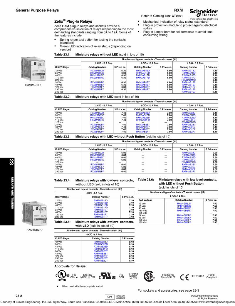
General Purpose Relays RXMRefer to Catalog 8501CT0601
Zelio® Plug-In RelaysZelio RXM plug-in relays and sockets provide a comprehensive selection of relays responding to the most demanding standards ranging from 3A to 12A. Some of the features include:• Spring return test button for testing the contacts
(standard)• Green LED indication of relay status (depending on
version)
• Mechanical indication of relay status (standard)• Plug-in protection module to protect against electrical
spikes• Plug-in jumper bars for coil terminals to avoid time-
consuming wiring
Approvals for Relays:
a When used with the appropriate socket.
For sockets and accessories, see page 23-3
RXM2AB1F7
RXM4GB2F7
Table 23.1: Miniature relays without LED (sold in lots of 10)
Number and type of contacts - Thermal current (Ith)
2 C/O -12 A Res. 3 C/O - 10 A Res. 4 C/O - 8 A Res.
Coil Voltage Catalog Number $ Price ea. Catalog Number $ Price ea. Catalog Number $ Price ea.
12 Vdc RXM2AB1JD 6.30 RXM3AB1JD 6.80 RXM4AB1JD 7.1024 Vdc RXM2AB1BD 6.30 RXM3AB1BD 6.80 RXM4AB1BD 7.1048 Vdc RXM2AB1ED 6.30 RXM3AB1ED 6.80 RXM4AB1ED 7.10110 Vdc RXM2AB1FD 6.30 RXM3AB1FD 6.80 RXM4AB1FD 7.10220 Vdc — — — — RXM4AB1MD 7.1024 Vac RXM2AB1B7 6.30 RXM3AB1B7 6.80 RXM4AB1B7 7.1048 Vac RXM2AB1E7 6.30 RXM3AB1E7 6.80 RXM4AB1E7 7.10120 Vac RXM2AB1F7 6.30 RXM3AB1F7 6.80 RXM4AB1F7 7.10230 Vac RXM2AB1P7 6.30 RXM3AB1P7 6.80 RXM4AB1P7 7.10240 Vac — — — — RXM4AB1U7 7.10
Table 23.2: Miniature relays with LED (sold in lots of 10)
Number and type of contacts - Thermal current (Ith)
2 C/O -12 A Res. 3 C/O - 10 A Res. 4 C/O - 8 A Res.
Coil Voltage Catalog Number $ Price ea. Catalog Number $ Price ea. Catalog Number $ Price ea.
12 Vdc RXM2AB2JD 7.40 RXM3AB2JD 7.80 RXM4AB2JD 8.1024 Vdc RXM2AB2BD 7.40 RXM3AB2BD 7.80 RXM4AB2BD 8.1048 Vdc RXM2AB2ED 7.40 RXM3AB2ED 7.80 RXM4AB2ED 8.10110 Vdc RXM2AB2FD 7.40 RXM3AB2FD 7.80 RXM4AB2FD 8.10125 Vdc — — — — RXM4AB2GD 8.1024 Vac RXM2AB2B7 7.40 RXM3AB2B7 7.80 RXM4AB2B7 8.1048 Vac RXM2AB2E7 7.40 RXM3AB2E7 7.80 RXM4AB2E7 8.10120 Vac RXM2AB2F7 7.40 RXM3AB2F7 7.80 RXM4AB2F7 8.10230 Vac RXM2AB2P7 7.40 RXM3AB2P7 7.80 RXM4AB2P7 8.10
Table 23.3: Miniature relays with LED without Push Button (sold in lots of 10)
Number and type of contacts - Thermal current (Ith)
2 C/O -12 A Res. 3 C/O - 10 A Res. 4 C/O - 8 A Res.
Coil Voltage Catalog Number $ Price ea. Catalog Number $ Price ea. Catalog Number $ Price ea.
12 Vdc RXM2AB3JD 6.80 — — RXM4AB3JD 7.5024 Vdc RXM2AB3BD 6.80 — — RXM4AB3BD 7.5048 Vdc RXM2AB3ED 6.80 — — RXM4AB3ED 7.50110 Vdc RXM2AB3FD 6.80 — — RXM4AB3FD 7.50125 Vdc — — — — RXM4AB3GD 7.5024 Vac RXM2AB3B7 6.80 — — RXM4AB3B7 7.5048 Vac RXM2AB3E7 6.80 — — RXM4AB3E7 7.50120 Vac RXM2AB3F7 6.80 — — RXM4AB3F7 7.50230 Vac RXM2AB3P7 6.80 — — RXM4AB3P7 7.50
Table 23.4: Miniature relays with low level contacts, without LED (sold in lots of 10)
Number and type of contacts - Thermal current (Ith)
4 C/O -3 A Res.
Coil Voltage Catalog Number $ Price ea.
12 Vdc RXM4GB1JD 7.1024 Vdc RXM4GB1BD 7.1048 Vdc RXM4GB1ED 7.10110 Vdc RXM4GB1FD 7.1024 Vac RXM4GB1B7 7.1048 Vac RXM4GB1E7 7.10120 Vac RXM4GB1F7 7.10230 Vac RXM4GB1P7 7.10
Table 23.5: Miniature relays with low level contacts, with LED (sold in lots of 10)
Number and type of contacts - Thermal current (Ith)
4 C/O -3 A Res.
Coil Voltage Catalog Number $ Price ea.
12 Vdc RXM4GB2JD 8.1024 Vdc RXM4GB2BD 8.1048 Vdc RXM4GB2ED 8.10110 Vdc RXM4GB2FD 8.1024 Vac RXM4GB2B7 8.1048 Vac RXM4GB2E7 8.10120 Vac RXM4GB2F7 8.10230 Vac RXM4GB2P7 8.10240 Vac RXM4GB2U7 8.10
Table 23.6: Miniature relays with low level contacts, with LED without Push Button(sold in lots of 10)
Number and type of contacts - Thermal current (Ith)
4 C/O -3 A Res.
Coil Voltage Catalog Number $ Price ea.
12 Vdc RXM4GB3JD 7.5024 Vdc RXM4GB3BD 7.5048 Vdc RXM4GB3ED 7.50110 Vdc RXM4GB3FD 7.50125 Vdc — —24 Vac RXM4GB3B7 7.5048 Vac RXM4GB3E7 7.50120 Vac RXM4GB3F7 7.50230 Vac RXM4GB3P7 7.50
FileCCN a
E164862NLDX, NLDX7
FileCCN
E164862NLDX2, NLDX8
File 230765Class 3211 07 IEC 61810-1 RoHS
Compliant
CP1 Discount Schedule
Courtesy of Steven Engineering, Inc.-230 Ryan Way, South San Francisco, CA 94080-6370-Main Office: (650) 588-9200-Outside Local Area: (800) 258-9200-www.stevenengineering.com

www.schneider-electric.us
23R
ELA
YS
AN
D T
IME
RS
© 2009 Schneider ElectricAll Rights Reserved
23-3
General Purpose Relays RXMRefer to Catalog 8501CT0601
a When mounting relay RXM2••••• on socket RXZE2M••••, the thermal current must not exceed 10 A.b Thermal current Ith: 10 Ac Thermal current lth: 12 A
Approvals for Sockets:
Table 23.7: Miniature relays (sold in lots of 100)
Number and type of contacts - Thermal current (Ith)
2 C/O - 12 A Res. 4 C/O - 8 A Res.
Coil Voltage Catalog Number $ Priceea. Catalog Number $ Price
ea.
Without LED
12 Vdc — — RXM4AB1JDTQ 7.1024 Vdc RXM2AB1BDTQ 6.30 RXM4AB1BDTQ 7.1048 Vdc — — RXM4AB1EDTQ 7.10110 Vdc — — RXM4AB1FDTQ 7.10220 Vdc — — RXM4AB1MDTQ 7.1024 Vac RXM2AB1B7TQ 6.30 RXM4AB1B7TQ 7.1048 Vac — — RXM4AB1E7TQ 7.10120 Vac RXM2AB1F7TQ 6.30 RXM4AB1F7TQ 7.10230 Vac RXM2AB1P7TQ 6.30 RXM4AB1P7TQ 7.10
With LED
24 Vdc — — RXM4AB2BDTQ 8.1024 Vac RXM2AB2B7TQ 7.40 RXM4AB2B7TQ 8.10230 Vac RXM2AB2P7TQ 7.40 RXM4AB2P7TQ 8.10
Table 23.8: Miniature relays with LED without Push Button (sold in lots of 100)
Number and type of contacts - Thermal current (Ith)
2 C/O - 12 A Res. 4 C/O - 8 A Res.
Coil Voltage Catalog Number $ Priceea. Catalog Number $ Price
ea.
24 Vdc RXM2AB3BDTQ 6.80 RXM4AB3BDTQ 7.5024 Vac RXM2AB3B7TQ 6.80 RXM4AB3B7TQ 7.50230 Vac RXM2AB3P7TQ 6.80 RXM4AB3P7TQ 7.50
Table 23.9: Sockets (sold in lots of 10)
Contact terminal arrangement Connection Relay type Catalog Number $ Priceea.
MixedScrew clamp terminals RXM2•••••a
RXM4•••••a RXZE2M114b 5.90
Box lug connector RXM2•••••RXM4••••• RXZE2M114Mb 5.90
Separate Box lug connectorRXM2••••• RXZE2S108Mc 5.90RXM3••••• RXZE2S111Mb 5.90RXM4••••• RXZE2S114Mb 5.90
Table 23.10: Protection modules (sold in lots of 20)
Description Voltage For use with Catalog Number $ Priceea.
Diode 6–250 Vdc All sockets RXM040W 2.30
RC circuit24–60 Vac All sockets RXM041BN7 2.30110–240 Vac All sockets RXM041FU7 2.30
Varistor6–24 Vac/Vdc All sockets RXM021RB 2.3024–60 Vac/Vdc All sockets RXM021BN 2.30110–240 Vac/Vdc All sockets RXM021FP 2.30
Table 23.11: Accessories (sold in lots of 10)
Description For use with Catalog Number $ Priceea.
Metal hold-down clip All sockets RXZ400 .57Plastic hold-down clip All sockets RXZR335 .57Bus jumper, 2-pole (Ith: 5 A) All sockets with separate contacts RXZS2 .84Mounting adapter for DIN rail All relays RXZE2DA .84Mounting adapter for mounting directly to a panel All relays RXZE2FA .57
Clip-in markersAll relays (sheet of 108 markers) RXZL520 .05All sockets except RXZE2M114 RXZL420 .05
FileCCN
E172326SWIV2, SWIV8
File 230765Class 3211 07 IEC 61810-1 RoHS
Compliant
RXZE2M114M with Relay RXM4AB2P7TQ
RXZE2S114M with relay RXM4AB2F7TQ
RXM041BN7
RXZ400
CP1 Discount Schedule
Courtesy of Steven Engineering, Inc.-230 Ryan Way, South San Francisco, CA 94080-6370-Main Office: (650) 588-9200-Outside Local Area: (800) 258-9200-www.stevenengineering.com

www.schneider-electric.us
23R
EL
AY
S A
ND
TIM
ER
S
23-4 © 2009 Schneider ElectricAll Rights Reserved
General Purpose Relays RPMRefer to Catalog 8501CT0601
Zelio® Plug-In RelaysZelio RPM plug-in relays and sockets provide a comprehensive selection of relays responding to the most demanding standards at 15 A. Some of the features include:• Spring return test button for testing the contacts (standard)• Green LED indication of relay status (depending on version)• Mechanical indication of relay status (standard)• Plug-in protection module to protect against electrical spikes
Approvals for relays:
Approvals for Sockets:
Table 23.12: Power relays without LED (sold in lots of 10)
Number and type of contacts - Thermal current (Ith)
1 C/O - 15 A Res. 2 C/O - 15 A Res. 3 C/O - 15 A Res. 4 C/O - 15 A Res.
Coil Voltage Catalog Number $ Price ea. Catalog Number $ Price ea. Catalog Number $ Price ea. Catalog Number $ Price ea.
12 Vdc RPM11JD 5.40 RPM21JD 7.10 RPM31JD 9.60 RPM41JD 11.9024 Vdc RPM11BD 5.40 RPM21BD 7.10 RPM31BD 9.60 RPM41BD 11.9048 Vdc RPM11ED 5.40 RPM21ED 7.10 RPM31ED 9.60 RPM41ED 11.90110 Vdc RPM11FD 5.40 RPM21FD 7.10 RPM31FD 9.60 RPM41FD 11.9024 Vac RPM11B7 5.40 RPM21B7 7.10 RPM31B7 9.60 RPM41B7 11.9048 Vac RPM11E7 5.40 RPM21E7 7.10 RPM31E7 9.60 RPM41E7 11.90120 Vac RPM11F7 5.40 RPM21F7 7.10 RPM31F7 9.60 RPM41F7 11.90230 Vac RPM11P7 5.40 RPM21P7 7.10 RPM31P7 9.60 RPM41P7 11.90
Table 23.13: Power relays with LED (sold in lots of 10)
Number and type of contacts - Thermal current (Ith)
1 C/O - 15 A Res. 2 C/O - 15 A Res. 3 C/O - 15 A Res. 4 C/O - 15 A Res.
Coil Voltage Catalog Number $ Price ea. Catalog Number $ Price ea. Catalog Number $ Price ea. Catalog Number $ Price ea.
12 Vdc RPM12JD 6.30 RPM22JD 8.10 RPM32JD 10.70 RPM42JD 12.9024 Vdc RPM12BD 6.30 RPM22BD 8.10 RPM32BD 10.70 RPM42BD 12.9048 Vdc RPM12ED 6.30 RPM22ED 8.10 RPM32ED 10.70 RPM42ED 12.90110 Vdc RPM12FD 6.30 RPM22FD 8.10 RPM32FD 10.70 RPM42FD 12.9024 Vac RPM12B7 6.30 RPM22B7 8.10 RPM32B7 10.70 RPM42B7 12.9048 Vac RPM12E7 6.30 RPM22E7 8.10 RPM32E7 10.70 RPM42E7 12.90120 Vac RPM12F7 6.30 RPM22F7 8.10 RPM32F7 10.70 RPM42F7 12.90230 Vac RPM12P7 6.30 RPM22P7 8.10 RPM32P7 10.70 RPM42P7 12.90
Table 23.14: Power relays with LED without Push Button (sold in lots of 10)
Number and type of contacts - Thermal current (Ith)
1 C/O - 15 A Res. 2 C/O - 15 A Res. 3 C/O - 15 A Res. 4 C/O - 15 A Res.
Coil Voltage Catalog Number $ Price ea. Catalog Number $ Price ea. Catalog Number $ Price ea. Catalog Number $ Price ea.
12 Vdc RPM13JD 5.90 RPM23JD 7.50 RPM33JD 9.90 RPM43JD 12.0024 Vdc RPM13BD 5.90 RPM23BD 7.50 RPM33BD 9.90 RPM43BD 12.0048 Vdc RPM13ED 5.90 RPM23ED 7.50 RPM33ED 9.90 RPM43ED 12.00110 Vdc RPM13FD 5.90 RPM23FD 7.50 RPM33FD 9.90 RPM43FD 12.00125 Vdc — — — — — — — —24 Vac RPM13B7 5.90 RPM23B7 7.50 RPM33B7 9.90 RPM43B7 12.0048 Vac RPM13E7 5.90 RPM23E7 7.50 RPM33E7 9.90 RPM43E7 12.00120 Vac RPM13F7 5.90 RPM23F7 7.50 RPM33F7 9.90 RPM43F7 12.00230 Vac RPM13P7 5.90 RPM23P7 7.50 RPM33P7 9.90 RPM43P7 12.00
FileCCN a
E164862NLDX, NLDX7
FileCCN
E164862NLDX2, NLDX8
File 230765Class 3211 07 IEC 61810-1 RoHS
Compliant
a When used with the appropriate socket
Table 23.15: Sockets (sold in lots of 10)
Contact terminal arrangement Connection Relay type Catalog Number $ Price ea.
Mixed Screw clamp terminals
RPM1••• RPZF1 5.10RPM2••• RPZF2 6.50RPM3••• RPZF3 7.50RPM4••• RPZF4 8.70
FileCCN
E172326SWIV2, SWIV8
File 230765Class 3211 07 IEC 61810-1 RoHS
Compliant
RPM22F7
RPM32F7
RPZF2 + relay RPM22F7
CP1 Discount Schedule
Courtesy of Steven Engineering, Inc.-230 Ryan Way, South San Francisco, CA 94080-6370-Main Office: (650) 588-9200-Outside Local Area: (800) 258-9200-www.stevenengineering.com
www.schneider-electric.us
23R
ELA
YS
AN
D T
IME
RS
© 2009 Schneider ElectricAll Rights Reserved
23-5
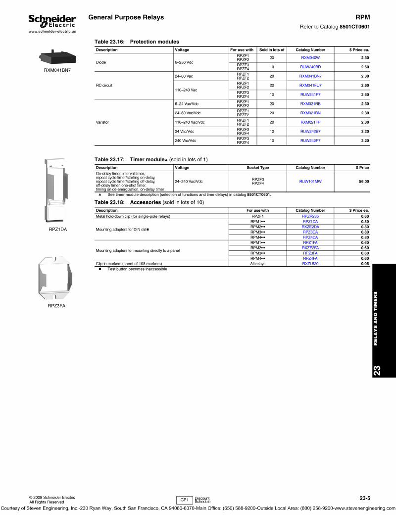
General Purpose Relays RPMRefer to Catalog 8501CT0601
a See timer module description (selection of functions and time delays) in catalog 8501CT0601.
b Test button becomes inaccessible
Table 23.16: Protection modulesDescription Voltage For use with Sold in lots of Catalog Number $ Price ea.
Diode 6–250 Vdc
RPZF1RPZF2 20 RXM040W 2.30
RPZF3RPZF4 10 RUW240BD 2.60
RC circuit
24–60 Vac RPZF1RPZF2 20 RXM041BN7 2.30
110–240 Vac
RPZF1RPZF2 20 RXM041FU7 2.60
RPZF3RPZF4 10 RUW241P7 2.60
Varistor
6–24 Vac/Vdc RPZF1RPZF2 20 RXM021RB 2.30
24–60 Vac/Vdc RPZF1RPZF2 20 RXM021BN 2.30
110–240 Vac/Vdc RPZF1RPZF2 20 RXM021FP 2.30
24 Vac/Vdc RPZF3RPZF4 10 RUW242B7 3.20
240 Vac/Vdc RPZF3RPZF4 10 RUW242P7 3.20
Table 23.17: Timer modulea (sold in lots of 1)
Description Voltage Socket Type Catalog Number $ Price
On-delay timer, interval timer,repeat cycle timer/starting on-delay,repeat cycle timer/starting off-delay,off-delay timer, one-shot timer,timing on de-energization, on-delay timer
24–240 Vac/Vdc RPZF3RPZF4 RUW101MW 56.00
Table 23.18: Accessories (sold in lots of 10)
Description For use with Catalog Number $ Price ea.
Metal hold-down clip (for single-pole relays) RPZF1 RPZR235 0.60
Mounting adapters for DIN railb
RPM1••• RPZ1DA 0.80RPM2••• RXZE2DA 0.80RPM3••• RPZ3DA 0.80RPM4••• RPZ4DA 0.80
Mounting adapters for mounting directly to a panel
RPM1••• RPZ1FA 0.60RPM2••• RXZE2FA 0.60RPM3••• RPZ3FA 0.60RPM4••• RPZ4FA 0.60
Clip-in markers (sheet of 108 markers) All relays RXZL520 0.05
RXM041BN7
RPZ1DA
RPZ3FA
CP1 Discount Schedule
Courtesy of Steven Engineering, Inc.-230 Ryan Way, South San Francisco, CA 94080-6370-Main Office: (650) 588-9200-Outside Local Area: (800) 258-9200-www.stevenengineering.com
www.schneider-electric.us
23R
EL
AY
S A
ND
TIM
ER
S
23-6 © 2009 Schneider ElectricAll Rights Reserved
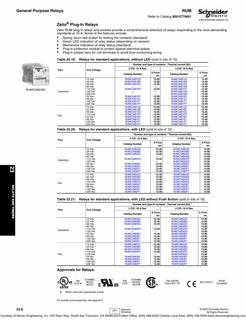
General Purpose Relays RUMRefer to Catalog 8501CT0601
Zelio® Plug-In RelaysZelio RUM plug-in relays and sockets provide a comprehensive selection of relays responding to the most demanding standards at 10 A. Some of the features include:• Spring return test button for testing the contacts (standard)• Green LED indication of relay status (depending on version)• Mechanical indication of relay status (standard)• Plug-in protection module to protect against electrical spikes• Plug-in jumper bars for coil terminals to avoid time-consuming wiring
Approvals for Relays:
For sockets and accessories, see page 23-7
Table 23.19: Relays for standard applications, without LED (sold in lots of 10)
Pins Coil Voltage
Number and type of contacts - Thermal current (Ith)
2 C/O -16 A Res. 3 C/O -16 A Res.
Catalog Number $ Priceea. Catalog Number $ Price
ea.
Cylindrical
12 Vdc RUMC2AB1JD 12.00 RUMC3AB1JD 13.4024 Vdc RUMC2AB1BD 12.00 RUMC3AB1BD 13.4048 Vdc RUMC2AB1ED 12.00 RUMC3AB1ED 13.4060 Vdc — — RUMC3AB1ND 13.40110 Vdc RUMC2AB1FD 12.00 RUMC3AB1FD 13.40125 Vdc — — RUMC3AB1GD 13.40220 Vdc — — RUMC3AB1MD 13.4024 Vac RUMC2AB1B7 12.00 RUMC3AB1B7 13.4048 Vac RUMC2AB1E7 12.00 RUMC3AB1E7 13.40120 Vac RUMC2AB1F7 12.00 RUMC3AB1F7 13.40230 Vac RUMC2AB1P7 12.00 RUMC3AB1P7 13.40
Flat
12 Vdc RUMF2AB1JD 12.00 RUMF3AB1JD 13.4024 Vdc RUMF2AB1BD 12.00 RUMF3AB1BD 13.4048 Vdc RUMF2AB1ED 12.00 RUMF3AB1ED 13.40110 Vdc RUMF2AB1FD 12.00 RUMF3AB1FD 13.4024 Vac RUMF2AB1B7 12.00 RUMF3AB1B7 13.4048 Vac RUMF2AB1E7 12.00 RUMF3AB1E7 13.40120 Vac RUMF2AB1F7 12.00 RUMF3AB1F7 13.40230 Vac RUMF2AB1P7 12.00 RUMF3AB1P7 13.40
Table 23.20: Relays for standard applications, with LED (sold in lots of 10)
Pins Coil Voltage
Number and type of contacts - Thermal current (Ith)
2 C/O -16 A Res. 3 C/O -16 A Res.
Catalog Number $ Priceea. Catalog Number $ Price
ea.
Cylindrical
12 Vdc RUMC2AB2JD 13.40 RUMC3AB2JD 14.9024 Vdc RUMC2AB2BD 13.40 RUMC3AB2BD 14.9048 Vdc RUMC2AB2ED 13.40 RUMC3AB2ED 14.9060 Vdc — — RUMC3AB2ND 14.90110 Vdc RUMC2AB2FD 13.40 RUMC3AB2FD 14.90125 Vdc — — RUMC3AB2GD 14.9024 Vac RUMC2AB2B7 13.40 RUMC3AB2B7 14.9048 Vac RUMC2AB2E7 13.40 RUMC3AB2E7 14.90120 Vac RUMC2AB2F7 13.40 RUMC3AB2F7 14.90230 Vac RUMC2AB2P7 13.40 RUMC3AB2P7 14.90
Flat
12 Vdc RUMF2AB2JD 13.40 RUMF3AB2JD 14.9024 Vdc RUMF2AB2BD 13.40 RUMF3AB2BD 14.9048 Vdc RUMF2AB2ED 13.40 RUMF3AB2ED 14.90110 Vdc RUMF2AB2FD 13.40 RUMF3AB2FD 14.9024 Vac RUMF2AB2B7 13.40 RUMF3AB2B7 14.9048 Vac RUMF2AB2E7 13.40 RUMF3AB2E7 14.90120 Vac RUMF2AB2F7 13.40 RUMF3AB2F7 14.90230 Vac RUMF2AB2P7 13.40 RUMF3AB2P7 14.90
Table 23.21: Relays for standard applications, with LED without Push Button (sold in lots of 10)
Pins Coil Voltage
Number and type of contacts - Thermal current (Ith)
2 C/O -16 A Res. 4 C/O -16 A Res.
Catalog Number $ Priceea. Catalog Number $ Price
ea.
Cylindrical
12 Vdc RUMC2AB3JD 12.40 RUMC3AB3JD 13.9024 Vdc RUMC2AB3BD 12.40 RUMC3AB3BD 13.9048 Vdc RUMC2AB3ED 12.40 RUMC3AB3ED 13.9060 Vdc — — RUMC3AB3ND 13.90110 Vdc RUMC2AB3FD 12.40 RUMC3AB3FD 13.90125 Vdc — — RUMC3AB3GD 13.9024 Vac RUMC2AB3B7 12.40 RUMC3AB3B7 13.9048 Vac RUMC2AB3E7 12.40 RUMC3AB3E7 13.90120 Vac RUMC2AB3F7 12.40 RUMC3AB3F7 13.90230 Vac RUMC2AB3P7 12.40 RUMC3AB3P7 13.90
Flat
12 Vdc RUMF2AB3JD 12.40 RUMF3AB3JD 13.9024 Vdc RUMF2AB3BD 12.40 RUMF3AB3BD 13.9048 Vdc RUMF2AB3ED 12.40 RUMF3AB3ED 13.90110 Vdc RUMF2AB3FD 12.40 RUMF3AB3FD 13.90125 Vdc — — RUMF3AB3GD 13.9024 Vac RUMF2AB3B7 12.40 RUMF3AB3B7 13.9048 Vac RUMF2AB3E7 12.40 RUMF3AB3E7 13.90120 Vac RUMF2AB3F7 12.40 RUMF3AB3F7 13.90230 Vac RUMF2AB3P7 12.40 RUMF3AB3P7 13.90
FileCCN a
E164862NLDX, NLDX7
FileCCN
E164862NLDX2, NLDX8
File 230765Class 3211 07 IEC 61810-1 RoHS
Compliant
a When used with appropriate socket
RUMC2AB1BD
CP1 Discount Schedule
Courtesy of Steven Engineering, Inc.-230 Ryan Way, South San Francisco, CA 94080-6370-Main Office: (650) 588-9200-Outside Local Area: (800) 258-9200-www.stevenengineering.com
www.schneider-electric.us
23R
ELA
YS
AN
D T
IME
RS
© 2009 Schneider ElectricAll Rights Reserved
23-7
General Purpose Relays RUMRefer to Catalog 8501CT0601
a The inputs are mixed with the relay coil terminals, with the outputs located on the opposite side of the socket.b The inputs and outputs are separated from the relay coil terminals.
c See timer module description (selection of functions and time delays) in catalog 8501CT0601.
Approvals for Sockets:
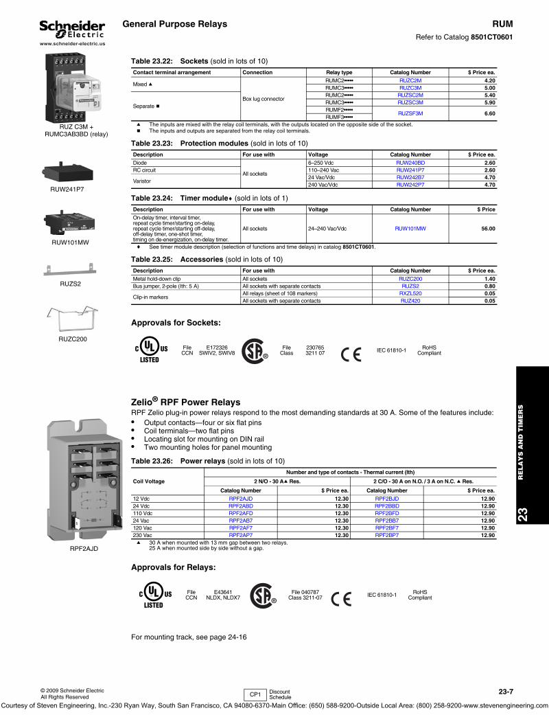
Zelio® RPF Power RelaysRPF Zelio plug-in power relays respond to the most demanding standards at 30 A. Some of the features include:• Output contacts—four or six flat pins• Coil terminals—two flat pins• Locating slot for mounting on DIN rail• Two mounting holes for panel mounting
a 30 A when mounted with 13 mm gap between two relays.25 A when mounted side by side without a gap.
Approvals for Relays:
For mounting track, see page 24-16
Table 23.22: Sockets (sold in lots of 10)
Contact terminal arrangement Connection Relay type Catalog Number $ Price ea.
Mixed a
Box lug connector
RUMC2••••• RUZC2M 4.20RUMC3••••• RUZC3M 5.00
Separate b
RUMC2••••• RUZSC2M 5.40RUMC3••••• RUZSC3M 5.90RUMF2•••••
RUZSF3M 6.60RUMF3•••••
Table 23.23: Protection modules (sold in lots of 10)
Description For use with Voltage Catalog Number $ Price ea.
Diode
All sockets
6–250 Vdc RUW240BD 2.60RC circuit 110–240 Vac RUW241P7 2.60
Varistor24 Vac/Vdc RUW242B7 4.70240 Vac/Vdc RUW242P7 4.70
Table 23.24: Timer modulec (sold in lots of 1)
Description For use with Voltage Catalog Number $ Price
On-delay timer, interval timer, repeat cycle timer/starting on-delay, repeat cycle timer/starting off-delay,off-delay timer, one-shot timer,timing on de-energization, on-delay timer.
All sockets 24–240 Vac/Vdc RUW101MW 56.00
Table 23.25: Accessories (sold in lots of 10)
Description For use with Catalog Number $ Price ea.
Metal hold-down clip All sockets RUZC200 1.40Bus jumper, 2-pole (Ith: 5 A) All sockets with separate contacts RUZS2 0.80
Clip-in markersAll relays (sheet of 108 markers) RXZL520 0.05All sockets with separate contacts RUZ420 0.05
FileCCN
E172326SWIV2, SWIV8
FileClass
2307653211 07 IEC 61810-1 RoHS
Compliant
Table 23.26: Power relays (sold in lots of 10)
Coil Voltage
Number and type of contacts - Thermal current (Ith)
2 N/O - 30 Aa Res. 2 C/O - 30 A on N.O. / 3 A on N.C. a Res.
Catalog Number $ Price ea. Catalog Number $ Price ea.
12 Vdc RPF2AJD 12.30 RPF2BJD 12.9024 Vdc RPF2ABD 12.30 RPF2BBD 12.90110 Vdc RPF2AFD 12.30 RPF2BFD 12.9024 Vac RPF2AB7 12.30 RPF2BB7 12.90120 Vac RPF2AF7 12.30 RPF2BF7 12.90230 Vac RPF2AP7 12.30 RPF2BP7 12.90
FileCCN
E43641NLDX, NLDX7
File 040787Class 3211-07 IEC 61810-1 RoHS
Compliant
RUZ C3M + RUMC3AB3BD (relay)
RUW241P7
RUW101MW
RUZS2
RUZC200
RPF2AJD
CP1 Discount Schedule
Courtesy of Steven Engineering, Inc.-230 Ryan Way, South San Francisco, CA 94080-6370-Main Office: (650) 588-9200-Outside Local Area: (800) 258-9200-www.stevenengineering.com
www.schneider-electric.us
23R
EL
AY
S A
ND
TIM
ER
S
23-8 © 2009 Schneider ElectricAll Rights Reserved
General Purpose Relays RSBRefer to Catalog 8501CT0601
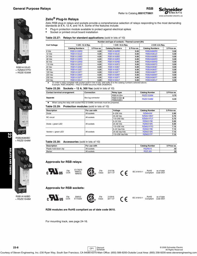
Zelio® Plug-In RelaysZelio RSB plug-in relays and sockets provide a comprehensive selection of relays responding to the most demanding standards at 8 A, 12 A, and 16 A. Some of the features include:• Plug-in protection module available to protect against electrical spikes• Socket or printed circuit board installation
a To order a relay complete with socket (sold in lots of 20): add suffix S to the catalog numbers selected above.Example: RSB 2A080RD + RSZ E1S48M becomes RSB 2A080RDS.
b When using the relay with socket RSZ E1S48M, terminals must be jumpered.
Approvals for RSB relays:
Approvals for RSB sockets:
RZM modules are RoHS compliant as of date code 0610.
For mounting track, see page 24-16.
Table 23.27: Relays for standard applications (sold in lots of 10)
Coil Voltage
Number and type of contacts - Thermal current (Ith)
1 C/O -12 A Res. 1 C/O -16 A Res. 2 C/O -8 A Res.
Catalog Numbera $ Price ea. Catalog Numbera $ Price ea. Catalog Numbera $ Price ea.
6 Vdc RSB1A120RD 4.20 RSB1A160RD 5.00 RSB2A080RD 5.0012 Vdc RSB1A120JD 4.20 RSB1A160JD 5.00 RSB2A080JD 5.0024 Vdc RSB1A120BD 4.20 RSB1A160BD 5.00 RSB2A080BD 5.0048 Vdc RSB1A120ED 4.20 RSB1A160ED 5.00 RSB2A080ED 5.0060 Vdc RSB1A120ND 4.20 RSB1A160ND 5.00 RSB2A080ND 5.00110 Vdc RSB1A120FD 4.20 RSB1A160FD 5.00 RSB2A080FD 5.0024 Vac RSB1A120B7 4.20 RSB1A160B7 5.00 RSB2A080B7 5.0048 Vac RSB1A120E7 4.20 RSB1A160E7 5.00 RSB2A080E7 5.00120 Vac RSB1A120F7 4.20 RSB1A160F7 5.00 RSB2A080F7 5.00220 Vac RSB1A120M7 4.20 RSB1A160M7 5.00 RSB2A080M7 5.00230 Vac RSB1A120P7 4.20 RSB1A160P7 5.00 RSB2A080P7 5.00240 Vac RSB1A120U7 4.20 RSB1A160U7 5.00 RSB2A080U7 5.00
Table 23.28: Sockets – 12 A, 300 Vac (sold in lots of 10)
Contact terminal arrangement Connection Relay type Catalog Number $ Price ea.
Separate Box lug connectorRSB1A120•• RSZE1S35M 5.70RSB1A160••bRSB2A080•• RSZE1S48M 6.30
Table 23.29: Protection modules (sold in lots of 10)
Description For use with Voltage Catalog Number $ Price ea.
Diode All sockets 6–230 Vdc RZM040W 2.90
RC circuit All sockets24–60 Vac RZM041BN7 5.70110–240 Vac RZM041FU7 5.70
Diode + green LED All sockets6–24 Vdc RZM031RB 5.0024–60 Vdc RZM031BN 5.00110–230 Vdc RZM031FPD 7.10
Varistor + green LED All sockets6–24 Vac/Vdc RZM021RB 7.1024–60 Vac/Vdc RZM021BN 7.10110–230 Vac/Vdc RZM021FP 7.10
Table 23.30: Accessories (sold in lots of 10)
Description For use with Catalog Number $ Price ea.
Plastic hold-down clip All sockets RSZR215 .42Marker All sockets RSZL300 .29
FileCCN
E173076NRNT2, NRNT8
FileClass
2157363211 07 IEC 61810-1 RoHS
Compliantas of date code 0401
FileCCN
SWIV2E172326
FileClass
2129163211 07 IEC 61810-1 RoHS
Compliantas of date code 0501
RSB1A120JD+ RZM031FPD+ RSZE1S35M
RSB1A160BD+ RSZE1S48M
RSB2A080BD+ RSZE1S48M
CP1 Discount Schedule
Courtesy of Steven Engineering, Inc.-230 Ryan Way, South San Francisco, CA 94080-6370-Main Office: (650) 588-9200-Outside Local Area: (800) 258-9200-www.stevenengineering.com
www.schneider-electric.us
23R
ELA
YS
AN
D T
IME
RS
© 2009 Schneider ElectricAll Rights Reserved
23-9
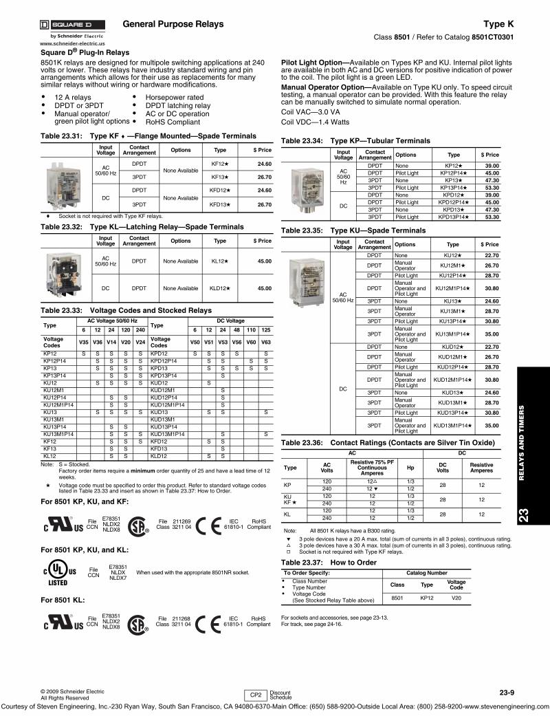
Square D® Plug-In Relays8501K relays are designed for multipole switching applications at 240 volts or lower. These relays have industry standard wiring and pin arrangements which allows for their use as replacements for many similar relays without wiring or hardware modifications.
c Socket is not required with Type KF relays.
Note: S = Stocked. Factory order items require a minimum order quantity of 25 and have a lead time of 12 weeks.
d Voltage code must be specified to order this product. Refer to standard voltage codes listed in Table 23.33 and insert as shown in Table 23.37: How to Order.
Pilot Light Option—Available on Types KP and KU. Internal pilot lights are available in both AC and DC versions for positive indication of power to the coil. The pilot light is a green LED.Manual Operator Option—Available on Type KU only. To speed circuit testing, a manual operator can be provided. With this feature the relay can be manually switched to simulate normal operation.Coil VAC—3.0 VACoil VDC—1.4 Watts
e 3 pole devices have a 20 A max. total (sum of currents in all 3 poles), continuous rating.f 3 pole devices have a 30 A max. total (sum of currents in all 3 poles), continuous rating.g Socket is not required with Type KF relays.
For sockets and accessories, see page 23-13.For track, see page 24-16.
• 12 A relays• DPDT or 3PDT• Manual operator/
green pilot light options
• Horsepower rated• DPDT latching relay• AC or DC operation• RoHS Compliant
Table 23.31: Type KF c —Flange Mounted—Spade TerminalsInput
VoltageContact
Arrangement Options Type $ Price
AC50/60 Hz
DPDTNone Available
KF12d 24.60
3PDT KF13d 26.70
DCDPDT
None AvailableKFD12d 24.60
3PDT KFD13d 26.70
Table 23.32: Type KL—Latching Relay—Spade TerminalsInput
VoltageContact
Arrangement Options Type $ Price
AC50/60 Hz DPDT None Available KL12d 45.00
DC DPDT None Available KLD12d 45.00
Table 23.33: Voltage Codes and Stocked Relays
TypeAC Voltage 50/60 Hz
TypeDC Voltage
6 12 24 120 240 6 12 24 48 110 125
Voltage Codes V35 V36 V14 V20 V24 Voltage
Codes V50 V51 V53 V56 V60 V63
KP12 S S S S S KPD12 S S S S SKP12P14 S S S S KPD12P14 S S S SKP13 S S S S KPD13 S S S S SKP13P14 S S S KPD13P14 SKU12 S S S S KUD12 SKU12M1 KUD12M1 SKU12P14 S S KUD12P14 SKU12M1P14 S S KUD12M1P14 SKU13 S S S S KUD13 S S SKU13M1 KUD13M1KU13P14 S S KUD13P14KU13M1P14 S S S KUD13M1P14 S SKF12 S S S KFD12 S SKF13 S S KFD13 SKL12 S S KLD12 S S
For 8501 KP, KU, and KF:
FileCCN
E78351NLDX2NLDX8
FileClass
2112693211 04
IEC 61810-1
RoHSCompliant
For 8501 KP, KU, and KL:
FileCCN
E78351NLDXNLDX7
When used with the appropriate 8501NR socket.
For 8501 KL:
FileCCN
E78351NLDX2NLDX8
FileClass
2112683211 04
IEC 61810-1
RoHSCompliant
Table 23.34: Type KP—Tubular TerminalsInput
VoltageContact
Arrangement Options Type $ Price
AC50/60
Hz
DPDT None KP12d 39.00DPDT Pilot Light KP12P14d 45.003PDT None KP13d 47.303PDT Pilot Light KP13P14d 53.30
DC
DPDT None KPD12d 39.00DPDT Pilot Light KPD12P14d 45.003PDT None KPD13d 47.303PDT Pilot Light KPD13P14d 53.30
Table 23.35: Type KU—Spade TerminalsInput
VoltageContact
Arrangement Options Type $ Price
AC50/60 Hz
DPDT None KU12d 22.70
DPDT Manual Operator KU12M1d 26.70
DPDT Pilot Light KU12P14d 28.70
DPDTManual Operator and Pilot Light
KU12M1P14d 30.80
3PDT None KU13d 24.60
3PDT Manual Operator KU13M1d 28.70
3PDT Pilot Light KU13P14d 30.80
3PDTManual Operator and Pilot Light
KU13M1P14d 35.00
DC
DPDT None KUD12d 22.70
DPDT Manual Operator KUD12M1d 26.70
DPDT Pilot Light KUD12P14d 28.70
DPDTManual Operator and Pilot Light
KUD12M1P14d 30.80
3PDT None KUD13d 24.60
3PDT Manual Operator KUD13M1d 28.70
3PDT Pilot Light KUD13P14d 30.80
3PDTManual Operator and Pilot Light
KUD13M1P14d 35.00
Table 23.36: Contact Ratings (Contacts are Silver Tin Oxide)AC DC
Type ACVolts
Resistive 75% PF Continuous
AmperesHp DC
VoltsResistive Amperes
KP 120 12f 1/3
28 12240 12 e 1/2
KU KF d
120 12 1/328 12
240 12 1/2
KL 120 12 1/3
28 12240 12 1/2
Note: All 8501 K relays have a B300 rating.
Table 23.37: How to OrderTo Order Specify: Catalog Number
• Class Number• Type Number• Voltage Code
(See Stocked Relay Table above)
Class Type Voltage Code
8501 KP12 V20
CP2 Discount Schedule
General Purpose Relays Type KClass 8501 / Refer to Catalog 8501CT0301
Courtesy of Steven Engineering, Inc.-230 Ryan Way, South San Francisco, CA 94080-6370-Main Office: (650) 588-9200-Outside Local Area: (800) 258-9200-www.stevenengineering.com
23R
EL
AY
S A
ND
TIM
ER
S
23-10 © 2009 Schneider ElectricAll Rights Reserved
www.schneider-electric.us
General Purpose Relays 8501KARefer to Catalog 8501CT9401
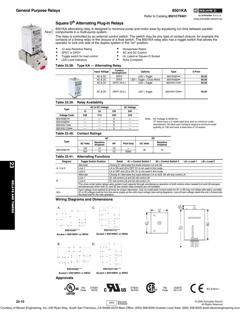
Square D® Alternating Plug-In Relays8501KA alternating relay is designed to minimize pump and motor wear by equalizing run time between parallel components in a multi-pump system.The relay is controlled by an external control switch. The switch may be any type of contact closure; for example the contacts of a timing relay or the closure of a float switch. The 8501KA relay also has a toggle switch that allows the operator to lock one side of the duplex system in the “on” position.
Wiring Diagrams and Dimensions
• 12 amp Resistive Rating• SPDT or DPDT• Toggle switch for load control• LED Load Indicators
• Horsepower Rated• AC and DC Control• UL Listed w/ Square D Socket• Rohs Compliant
Table 23.38: Type KA — Alternating Relay
Input Voltage ContactArrangement Options Type $ Price
AC & DC SPDT LED + Toggle 8501KA81••• 95.00AC & DC DPDT LED + Toggle + Cross Wired 8501KA82••• 95.00AC & DC DPDT (N.C.) LED + Toggle 8501KA112••• 95.00
AC & DC DPDT (N.O.) LED + Toggle 8501KA112A••• 95.00
Table 23.39: Relay Availability
TypeAC & DC Voltage AC Voltage
12 24 120 240
Voltage Code V36 V14 V20 V24
8501KA81••• — — S — Note: AC Voltage is 50/60 Hz“S” items have a 2 week lead time and no minimum order requirement. All other part numbers require a minimum order quantity of 100 and have a lead-time of 18 weeks.
8501KA82••• — — S —8501KA112••• — — S —8501KA112A••• — — S —
Table 23.40: Contact Ratings
TypeAC DC
AC Volts Resistive Amperes HP Pilot Duty DC Volts Resistive
Amperes
8501KA81•••120 12 1/3 —
30 12240 12 1/2 B300
Table 23.41: Alternating FunctionsDiagram Toggle Switch Position Detail S1 = Control Switch 1 S2 = Control Switch 2 LA = Load 1 LB = Load 2
A, C & DAlternate Closing S1 alternates the loads between LA and LB.Lock 1 LA is ON and LB is OFF. S1 is not used in this mode.Lock 2 LA is OFF and LB is ON. S1 is not used in this mode.
B
Alternate Closing S1 alternates the loads between LA an dLB. S2 will only control LA.Lock 1 S1 will control LA and S2 will control LBLock 2 S1 will control LB and S2 will control LA.The cross wired option allows extra system load capacity through simultaneous operation of both motors when needed (LA and LB energize simultaneously when both S1 and S2 are closed–relay contacts are not isolated)
ALLInput voltage must applied at all times for proper alternation. Use of a solid state control switch for S1 or S2 may not initiate alternation corredtly. S1 or S2 voltage must be from the same supply as the unit’s input voltage (see wiring diagrams). Loss of input voltage resets the unit; LA becomes the lead load for the next operation.
New!
8501KA81···Socket = 8501NR51 or NR52
8501KA112···Socket = 8501NR61 or NR62
8501KA82···Socket = 8501NR51 or NR52
8501KA112A···Socket = 8501NR61 or NR62
.C.A
.D.B
CP2 Discount Schedule
Approvals
FileClass
E78351NLDX
E78351NLDX2
FileClass
2426753211-07 IEC 61810-1
Courtesy of Steven Engineering, Inc.-230 Ryan Way, South San Francisco, CA 94080-6370-Main Office: (650) 588-9200-Outside Local Area: (800) 258-9200-www.stevenengineering.com

www.schneider-electric.us
23R
ELA
YS
AN
D T
IME
RS
© 2009 Schneider ElectricAll Rights Reserved
23-11
Square D® Miniature Plug-in Relays8501R miniature plug-in relays have a 10 A resistive rating, the same as the Type K plug-in relays, but are much smaller. The compact size of these relays makes them ideal for downsizing equipment.
a Relays have a B300 rating with UL.
b Voltage code must be specified to order this product. Refer to standard voltage codes listed in Table 23.43 and insert as shown in Table 23.49: How to Order.
c When used with the appropriate 8501NR socket.
For sockets and accessories, see page 23-13. For track, see page 24-16.
• SPDT through 4PDT• AC or DC operated• Horsepower rated• Socket compatible
• Manual operator/ green LED pilot light options
• Silver tin oxide contacts
Table 23.42: Contact Ratings (Contact material is Silver Tin Oxide)
Type Voltage ResistiveRating Voltage General Use
RatingHorsepower Rating
8501RS41 a120 Vac 15 120 Vac 10 1/2 @120 Vac240 Vac 10 240 Vac 10 1 @240 Vac
8501RSD41a 28 Vdc 15 28 Vdc 15 —
8501RS42a120 Vac 10 120 Vac 10 1/3 @120 Vac240 Vac 10 240 Vac 10 1/2 @240 Vac
8501RSD42a 30 Vdc 10 28 Vdc 10 —
8501RS43a120 Vac 12 150 Vac 10 1/2 @120 Vac277 Vac 12 250 Vac 6.6 3/4 @240 Vac
8501RSD43a 28 Vdc 12 28 Vdc 10 —
8501RS44a120 Vac 12 150 Vac 7.5 1/2 @120 Vac277 Vac 12 250 Vac 5 3/4 @240 Vac
8501RSD44a 28 Vdc 12 28 Vdc 10 —
Table 23.43: Voltage Codes and Stocked Relays
TypeAC Voltage 50/60 Hz
TypeDC Voltage
6 12 24 120 240 6 12 24 110
Voltage Code V35 V36 V14 V20 V24 Voltage Code V50 V51 V53 V60
RS41 S S RSD41 S SRS41M1 RSD41M1RS41P14 S S RSD41P14 S
RS41M1P14 S S RSD41M1P14 SRS42 S S S S RSD42 S S
RS42M1 RSD42M1RS42P14 S S RSD42P14 S S
RS42M1P14 S RSD42M1P14 SRS43 S S RSD43 S
RS43M1 RSD43M1RS43P14 S RSD43P14
RS43M1P14 S RSD43M1P14RS44 S S S RSD44 S S
RS44M1 RSD44M1RS44P14 S RSD44P14 S
RS44M1P14 S RSD44M1P14Note: S = Stocked.
Factory order items require a minimum order quantity of 25 and have a lead time of 12 weeks.
Table 23.44: SPDT with Silver Tin Oxide ContactsInput Voltage Options Type $ Price
AC50/60Hz
None RS41b 29.60
Manual Operator RS41M1b 31.70
Pilot Light RS41P14b 37.20
Manual Operator and Pilot Light RS41M1P14b 39.30
DC
None RSD41b 29.60
Manual Operator RSD41M1b 31.70
Pilot Light RSD41P14b 37.20
Manual Operator and Pilot Light RSD41M1P14b 29.60
Table 23.45: DPDT with Silver Tin Oxide ContactsInput Voltage Options Type $ Price
AC50/60Hz
None RS42b 35.00
Manual Operator RS42M1b 37.10
Pilot Light RS42P14b 43.10
Manual Operator and Pilot Light RS42M1P14b 45.20
DC
None RSD42b 35.00
Manual Operator RSD42M1b 37.10
Pilot Light RSD42P14b 43.10
Manual Operator and Pilot Light RSD42M1P14b 45.20
Table 23.46: 3PDT with Silver Tin Oxide ContactsInput Voltage Options Type $ Price
AC50/60Hz
None RS43b 39.30
Manual Operator RS43M1b 41.40
Pilot Light RS43P14b 47.60
Manual Operator and Pilot Light RS43M1P14b 49.90
DC
None RSD43b 39.30
Manual Operator RSD43M1b 41.40
Pilot Light RSD43P14b 47.60
Manual Operator and Pilot Light RSD43M1P14b 49.90
Table 23.47: 4PDT with Silver Tin Oxide ContactsInput Voltage Options Type $ Price
AC50/60Hz
None RS44b 44.30
Manual Operator RS44M1b 46.20
Pilot Light RS44P14b 52.30
Manual Operator and Pilot Light RS44M1P14b 54.50
DC
None RSD44b 44.30
Manual Operator RSD44M1b 46.20
Pilot Light RSD44P14b 52.30
Manual Operator and Pilot Light RSD44M1P14b 54.50
Table 23.48: Application DataClass 8501 Type RS41 RSD41 RS42 RSD42 RS43 RSD43 RS44 RSD44
Operating DataPick-Up Time 20 ms Maximum 25 ms Maximum 20 ms Maximum
Drop-Out Time 20 ms MaximumOperating Temperature -40oC to +70oC (-40oF to +158oF)
Coil
Duty Cycle ContinuousVoltage Range AC coils +10%, -15% of nominal DC coils +10%, -20% of nominal
AC Coils–Inrush 9 VA — 6.2 VA — 10.3 VA — 11.9 VA —AC Coils–Sealed 1.5 VA — 1.2 VA — 1.7 VA — 2.1 VA —
DC Coils — 0.9 watts — 0.9 watts — 1.4 watts — 1.5 watts
UR FileCCN
E78351NLDX2, NLDX8
CSA FileClass
2112683218 07
CE marked yesRoHS Compliant yes
UL Listed FileCCN
E78351cNLDX, NLDX7
Table 23.49: How to OrderTo Order Specify: Catalog Number
• Class Number• Type Number• Voltage Code (see Table 23.43)
Class Type Voltage Code
8501 RS42 V20
CP2 Discount Schedule
General Purpose Relays Type RClass 8501 / Refer to Catalog 8501CT0301
Courtesy of Steven Engineering, Inc.-230 Ryan Way, South San Francisco, CA 94080-6370-Main Office: (650) 588-9200-Outside Local Area: (800) 258-9200-www.stevenengineering.com

www.schneider-electric.us
23R
EL
AY
S A
ND
TIM
ER
S
23-12 © 2009 Schneider ElectricAll Rights Reserved
General Purpose Relays Type RClass 8501 / Refer to Catalog 8501CT0301
Square D® Miniature Plug-in Relays8501R relays are suited for use as logic elements and power switching output devices. The short stroke motion of the armature provides long mechanical life required for high speed operation of control systems. Different contact compositions allow these relays to be used in a variety of applications. Fine silver (gold flashed) and bifurcated crossbar (gold overlay silver) are suitable for high contact reliability and low level switching requirements. Silver tin oxide is best suited for inductive loads. Hermetically sealed relays can be used in adverse environments.
a Voltage code must be specified to order this product. Refer to standard voltage codes shown in Table 23.55.
b Do not ground the frame.
Pilot Light OptionAn internal green pilot light is available in both AC and DC versions for positive indication of power to the coil.
Manual Operation OptionTo speed circuit testing, a manual operator can be provided. The relay can be manually switched to simulate normal operation.NOTE: All Type R relays with a manual operator must
be used on circuits of the same polarity.
c RS4/RSD4, RS14/RSD14 have NEMA C300 pilot duty rating.
Note: S = Stocked. Factory Order items require a minimum order quantity of 25 and have a lead time of 12 weeks.
For sockets and accessories, see page 23-13. For track, see page 24-16.
• 1, 3, or 5 A versions• 4PDT• Complete socket line
• Horsepower rated• AC or DC operation• Manual operator/pilot
light options
Table 23.50: 5 A Version
5 A Input Voltage Options Type $ Price
For switchinginductive
loads
AC50/60
Hz
None RS14a 32.70Manual Operator RS14M1a 35.00Pilot Light RS14P14a 40.90Manual Operatorand Pilot Light RS14M1P14a 43.10
Contacts:Silver Tin
OxideDC
None RSD14a 27.70Manual Operator RSD14M1a 30.80Pilot Light RSD14P14a 36.80Manual Operatorand Pilot Light RSD14M1P14a 39.00
Table 23.51: 3 A Version
3 A Input Voltage Options Type $ Price
For low levelswitching
AC50/60
Hz
None RS4a 32.70Manual Operator RS4M1a 35.00Pilot Light RS4P14a 40.90Manual Operatorand Pilot Light RS4M1P14a 43.10
Contacts:Fine Silver
(Gold Flashed)
DC
None RSD4a 28.70Manual Operator RSD4M1a 30.80Pilot Light RSD4P14a 36.80Manual Operatorand Pilot Light RSD4M1P14a 39.00
Table 23.52: 1 A Version1 A Input Voltage Type $ Price
Best for Low Level Switching AC 50/60 Hz RS24a 53.00Bifurcated Silver Gold-Plated Contacts DC RSD24a 53.00
Table 23.53: 5 A Version, Hermetically Sealed5 A, Hermetically Sealed Input Voltage Type $ Price
5 Ampere Resistive bSilver Tin Oxide Contacts AC 50/60 Hz RS34a 53.00
Suitable for Class I Division 2 Locations DC RSD34a 53.00
8501RSD14P14V53 Table 23.54: Contact Ratings (Contact material is Silver Tin Oxide)
Type Voltage Continuous Current Rating
Horsepower Rating
RS4 cRSD4 c
120/240 Vac 3 1/1030 Vdc 3 —
RS14 cRSD14 c
120/240 Vac 5 1/628 Vdc 5 —
RS24RSD24
120/240 Vac 1 1/16 (2.8 FLA)30 Vdc 1 —
RS34RSD34
120/240 Vac 5 —30 Vdc 5 —
Table 23.55: AC Voltage Codes and Stocked Relays
TypeAC Voltage 50/60 Hz
6 12 24 48 120 240
Voltage Code V35 V36 V14 V17 V20 V24
RS4 S SRS4M1 SRS4P14 SRS4M1P14 SRS14 S S SRS14M1 SRS14P14 SRS14M1P14 S SRS24 SRS34 S
Table 23.56: DC Voltage Codes and Stocked Relays
TypeDC Voltage
6 12 24 48 110
Voltage Code V50 V51 V53 V56 V60
RSD4 S SRSD4M1RSD4P14 SRSD4M1P14 SRSD14 S S SRSD14M1 SRSD14P14 S S SRSD14M1P14 S SRSD24 SRSD34 S S
8501RS14M1V14
8501RSD34V51
Table 23.57: Application DataClass 8501 Type RS4 RSD4 RS14 RSD14 RS24 RSD24 RS34 RSD34
Operating Data
Pick-Up Time 20 ms Maximum 13 ms Max.Drop-Out Time 20 ms Maximum 6 ms Max.Operating Temperature Range -40oC to +70oC (-40oF to +158oF) -40oC to +70oC (-40oF to +158oF)
Coil
Duty Cycle Continuous
Voltage Range AC coils +10%, -15% of nominal and DC coils +10%, -20% of nominal
AC Coils—Sealed 1.2 VA — 1.2 VA — 1.2 VA — 1.2 VA —AC Coils—Inrush 6.2 VA — 6.2 VA — 6.2 VA — 6.0 VA —DC Coils — 0.9 watt — 0.9 watt — 0.9 watt — 0.9 watt
Approvals
UR File: E197072 CCN: NRNT2 N/AC UR US File: E197072 CCN: NRNT8 (Approved but not marked) File: E196809 CCN: NQMJ2, NQMJ8CSA File: 211268 Class: 3218 07 File: 211268 Class: 3218 06CE marked YesRoHS Compliant YesUL Listed File E78351 CCN NLDX, NLDX7d
d When used with the appropriate 8501 NR Socket.
CP2 Discount Schedule
Courtesy of Steven Engineering, Inc.-230 Ryan Way, South San Francisco, CA 94080-6370-Main Office: (650) 588-9200-Outside Local Area: (800) 258-9200-www.stevenengineering.com

www.schneider-electric.us
23R
ELA
YS
AN
D T
IME
RS
© 2009 Schneider ElectricAll Rights Reserved
23-13
General Purpose Relays Type NClass 8501 / Refer to Catalog 8501CT0301
Square D® Sockets
8501NR sockets are designed for use with plug-in Class 8501 Type K, KA, and R relays, 8430MPS phase failure relays and 9050JCK timers. The 8501NR45 screw terminal sockets have pressure wire clamps that accept 1 or 2 #16–22 wires. All other sockets have pressure clamps that will accept 1 or 2 #12–22 wires.The recommended tightening torque for all terminals is 7-8 lb-in.• All devices stocked in central warehouse• DIN track mount or direct panel mount• Tubular sockets available in easy-to-wire single tier or double tier versions• RoHS compliant
a Must be ordered in multiples of the quantity listed. Units provided in standard quantity of one are individually packaged; devices with B suffix have a standard quantity of 10 per bulk pack.
b Rated for use with Class 8430 Type MPS at 480 Volts. Rated 10 A at 300 volts by CSA. c Finger Safe
For DIN 3 mounting track and end clamps, see page 24-16, or refer to:• NEMA Style terminal block section of catalog 9080CT9601• IEC Style terminal block section of catalog 9080CT9901
d Must be ordered in multiples of the quantity listed.
Table 23.58: Snapmount SocketsFor Use With Class:
DescriptionSocket Rating
Type $ Priceea.
Std.Qty.a8501
Type8430 Type
9050 Type UL CSA
KP12KPD12KA81KA82
MPS(240 volts)
JCK11–19JCK31–39JCK51–59
JCK60JCK1 FJCK3 FJCK5 F
8 Pin TubularSingle Tier Screw Terminal
600 V, 10 A300 V, 10 A
NR51 12.30 1300 V, 15 A NR51B 10.20 10
8 Pin TubularDouble Tier Screw Terminal
600 V, 5 A
300 V, 10 A
NR52c 12.30 1
300 V, 16 A NR52Bc 10.20 10
KP13KPD13KA112
—
JCK21–29JCK41–49
JCK70JCK2FJCK4F
11 Pin TubularSingle Tier Screw Terminal
600 V, 5 A300 V, 10 A
NR61 18.50 1300 V, 15 A NR61B 16.50 10
11 Pin TubularDouble Tier Screw Terminal
600 V, 5 A300 V, 10 A
NR62c 18.50 1300 V, 16 A NR62Bc 16.50 10
KLKU
MPS(480 Volts) — 11 Pin Spade
Double Tier Screw Terminal 300 V, 15 A 300 V, 15 AbNR82 20.60 1
NR82B 18.50 10
RS41RSD41 — — 5 Pin Spade
Double Tier Screw Terminal 300 V, 15 A 300 V, 15 ANR41c 28.70 1
NR41Bc 26.70 10
RS42RSD42 — — 8 Pin Spade
Double Tier Screw Terminal 300 V, 10 A 300 V, 10 ANR42 28.70 1
NR42B 26.70 10
RS43RSD43 — — 11 Pin Spade
Double Tier Screw Terminal 300 V, 10 A 300 V, 10 ANR43 26.70 1
NR43B 26.70 10
RS44RSD44 — — 14 Pin Spade
Double Tier Screw Terminal 300 V, 10 A 300 V, 10 ANR34 28.70 1
NR34B 26.70 10
RS4RSD4RS14
RSD14RS24
RSD24RS34
RSD34
— — 14 Pin SpadeDouble Tier Screw Terminal 300 V, 10 A 300 V, 10 A
NR45 28.70 1
NR45B 26.70 10
Table 23.59: Socket AccessoriesSocket For Use With Description Type $ Price ea. Std. Pack d
8501NR518501KP12, KPD12 Hold Down Clip NH51 1.00 108430MPSV24 Hold Down Spring NH7 8.30 19050JCK Hold Down Spring NH7 8.30 1
8501NR528501KP12, KPD12 Hold Down Clip NH52 1.00 108430MPSV24 Hold Down Spring NH7 8.30 19050JCK Hold Down Spring NH7 8.30 1
8501NR618501KP13, KPD13 Hold Down Clip NH61 1.00 109050JCK Hold Down Spring NH7 8.30 1
8501NR628501KP13, KPD13 Hold Down Clip NH52 1.00 109050JCK Hold Down Spring NH7 8.30 1
8501NR828501KU and KL Hold Down Clip NH82 1.00 108430MPSV29 Hold Down Spring NH7 8.30 1
8501NR41 8501RS41, RSD41 Hold Down Clip Supplied with socket as standard — —8501NR42 8501RS42, RSD42 Hold Down Clip 8501NH42 1.00 108501NR43 8501RS43, RSD43 Hold Down Clip 8501NH42 1.00 108501NR34 8501RS44, RSD44 Hold Down Clip 8501NH42 1.00 10
8501NR45
8501RS4, RSD48501RS14, RSD148501RS24, RSD248501RS34, RSD34
Hold Down Clip 8501NH45 1.00 10
8501NR51 8501NR61
8501NR52 8501NR62
8501NR82 8501NR45
8501NR41 8501NR42
8501NR43
8501NH7
8501NR34
How to OrderTo Order Specify: Catalog Number
• Class Number• Type Number
Class Type
8501 NR51B
Approvals:
FileCCN
E66924SW1V2
FileClass
2112683211 07
IEC61810-1
RoHSCompliant
as of date code 0639
CP2 Discount Schedule
Courtesy of Steven Engineering, Inc.-230 Ryan Way, South San Francisco, CA 94080-6370-Main Office: (650) 588-9200-Outside Local Area: (800) 258-9200-www.stevenengineering.com

www.schneider-electric.us
23R
EL
AY
S A
ND
TIM
ER
S
23-14 © 2009 Schneider ElectricAll Rights Reserved
Approximate Dimensions
Note: S = Stocked. Factory order items require a minimum order quantity of 25 and have a lead time of 12 weeks.
EnclosureNEMA 1 sheet steel enclosure
Square D® Power Relays8501C relays are ideally suited for controlling small single phase motors and other light loads such as electric heaters, pilot lights or audible signals.
• 30 A contact rating • UL listed
• Horsepower rated • CSA certified
• Visible contacts • CE approved
• Low cost8501CDO6V51
Table 23.60: Selection Table and Application DataSelection Table Application Data Application Data—Coil Burden
ContactArrangement
Numberof FixedContacts
AC Operated CoilOpen Type
DC Operated CoilOpen Type
MaximumContactVoltage
Resistive Ampere Rating 75% Power Factor
MaximumSingle PhaseHorsepower
NominalPower(Vac Coil)
NominalDCBurden(Vdc Coil)N.O. N.C. Type $ Price Type $ Price 300 V 600 V 120 V 230 V 600 V
AC Rated Contacts
SPST 1 0 CO6a 32.70 CDO6a 32.70 600 30 10 2 2 2 10 VA 2 WDPST 2 0 CO7a 51.30 CDO7a 51.30 600 30 5 1 1 1 10 VA 2 WSPST 0 1 CO8a 32.70 CDO8a 32.70 600 30 10 2 2 2 10 VA 2 WSPDT 1 1 CO15a 57.30 CDO15a 57.30 600 30 5 1 1 1 10 VA 2 WDPDT 2 2 CO16a 69.60 CDO16a 69.60 600 30 5 1 1 1 10 VA 2 W
DC Rated Contacts 110 V 220 V
SPST 1 0 CO21a 71.70 CDO21a 71.70 500 20 8N.A.
10 VA 2 WDPDT 2 2 CO22a 84.00 CDO22a 84.00 325 10 4 10 VA 2 W
a Voltage codes must be specified to order this product. Refer to standard voltage codes listed in Table 23.63 and insert as shown in Table 23.65: How to Order.
Table 23.61: Operating DataOperating Voltages/Voltage Range
AC – 6 through 480 volts, + 10/-15% of nominal at 25 oCDC – 6 through 110 volts, + 10/-20% of nominal at 25 oC
Coil Inrush (Vac Coil) 15 VA
Coils Duty: Continuous rated coils. (Non-replaceable)
Operating Temp. Range AC: -22 oF to +122 oF (-30 oC to +50 oC)DC: -22 oF to +140 oF (-30 oC to +60 oC)
Approvals:
FileCCN
E78351NLDX
FileClass
2181393211 04 IEC 60947-4-1
Table 23.62: Dimensions
Catalog Number 8501••••
A B C D E F
in. mm in. mm in. mm in. mm in. mm in. mm
CO6, CO7, CO8, CDO6, CDO7, CDO8
2.43 61.7 2.50 63.5 0.31 8.0 0.81 20.6 2.25 57.2 0.37 9.5
CO15, CO21, CDO15, CDO21 2.43 61.7 2.50 63.5 0.31 8.0 0.81 20.6 2.18 55.4 0.37 9.5
CO16,CDO16 3.12 79.2 2.50 63.5 0.31 8.0 1.5 38.1 2.31 58.7 0.37 9.5CO22, CDO22 3.12 79.2 2.50 63.5 0.31 8.0 1.5 38.1 2.53 64.3 0.37 9.5
A
D C
B E
F
(2) #10 Mtg. Screws B65075-021-A
Table 23.63: Voltage Codes and Stocked RelaysClass8501Type
AC Voltage—50/60 Hz Class8501Type
DC Voltage
6 12 24 120 208 240 277 480 6 12 24 110
Voltage Code V35 V36 V14 V20 V08 V24 V04 V29 Voltage
Code V50 V51 V53 V60
CO6 S S S S S S S CDO6 S SCO7 S S S S S S S CDO7 S SCO8 S S S S S CDO8CO15 S S S S S S CDO15 SCO16 S S S S S S S CDO16 S S SCO21 S CDO21 S SCO22 S CDO22 S S
Table 23.64: Class 9991Type $ Price
UE1 19.70
Table 23.65: How to OrderTo Order Specify: Catalog Number
• Class Number• Type Number• Voltage Code
(See Stocked Relay Table above)
Class Type Voltage Code
8501 CO6 V20
9991UE1
CP2 Discount Schedule
General Purpose Relays Type CClass 8501 / Refer to Catalog 8501CT0301
Courtesy of Steven Engineering, Inc.-230 Ryan Way, South San Francisco, CA 94080-6370-Main Office: (650) 588-9200-Outside Local Area: (800) 258-9200-www.stevenengineering.com
www.schneider-electric.us
23R
ELA
YS
AN
D T
IME
RS
© 2009 Schneider ElectricAll Rights Reserved
23-15
Industrial Relays CADRefer to Catalog 8501CT0101
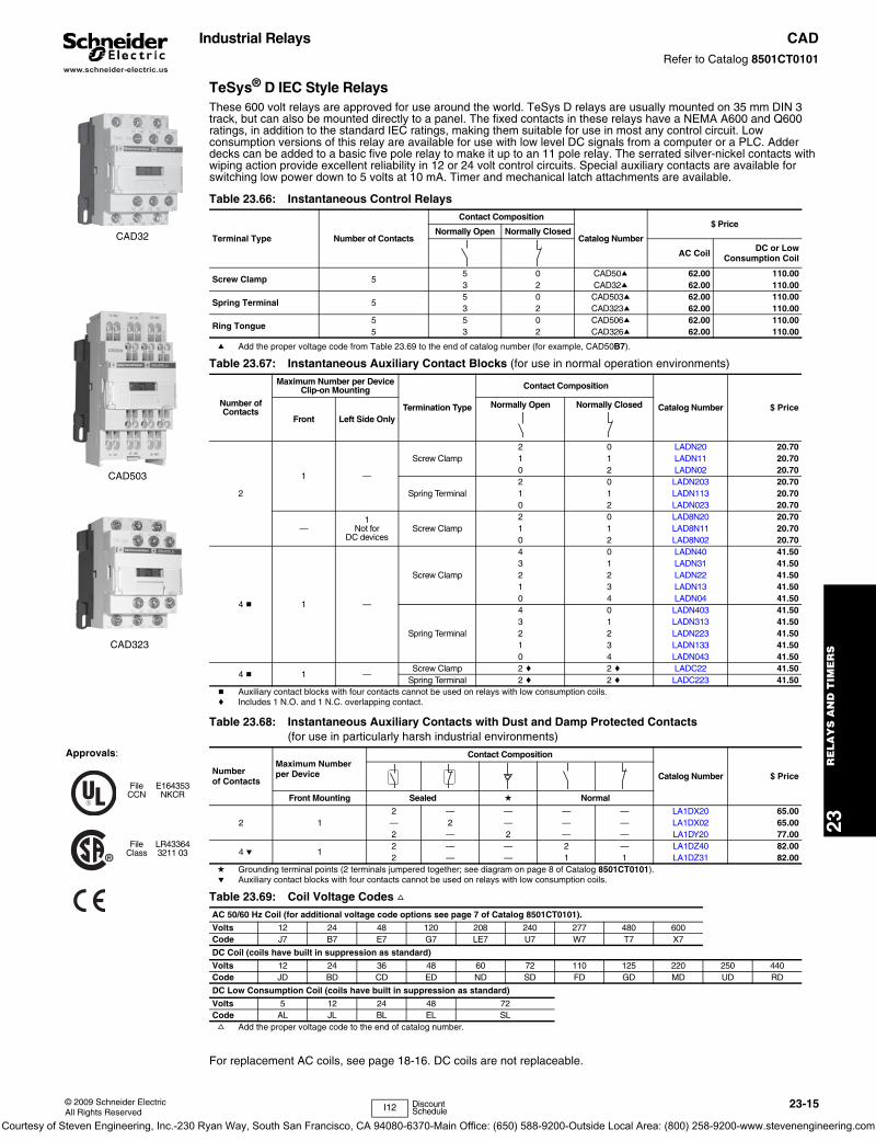
TeSys® D IEC Style RelaysThese 600 volt relays are approved for use around the world. TeSys D relays are usually mounted on 35 mm DIN 3 track, but can also be mounted directly to a panel. The fixed contacts in these relays have a NEMA A600 and Q600 ratings, in addition to the standard IEC ratings, making them suitable for use in most any control circuit. Low consumption versions of this relay are available for use with low level DC signals from a computer or a PLC. Adder decks can be added to a basic five pole relay to make it up to an 11 pole relay. The serrated silver-nickel contacts with wiping action provide excellent reliability in 12 or 24 volt control circuits. Special auxiliary contacts are available for switching low power down to 5 volts at 10 mA. Timer and mechanical latch attachments are available.
a Add the proper voltage code from Table 23.69 to the end of catalog number (for example, CAD50B7).
b Auxiliary contact blocks with four contacts cannot be used on relays with low consumption coils.c Includes 1 N.O. and 1 N.C. overlapping contact.
d Grounding terminal points (2 terminals jumpered together; see diagram on page 8 of Catalog 8501CT0101).e Auxiliary contact blocks with four contacts cannot be used on relays with low consumption coils.
f Add the proper voltage code to the end of catalog number.
For replacement AC coils, see page 18-16. DC coils are not replaceable.
Table 23.66: Instantaneous Control Relays
Terminal Type Number of Contacts
Contact Composition
Catalog Number
$ PriceNormally Open Normally Closed
AC Coil DC or LowConsumption Coil
Screw Clamp 55 0 CAD50a 62.00 110.003 2 CAD32a 62.00 110.00
Spring Terminal 55 0 CAD503a 62.00 110.003 2 CAD323a 62.00 110.00
Ring Tongue5 5 0 CAD506a 62.00 110.005 3 2 CAD326a 62.00 110.00
Table 23.67: Instantaneous Auxiliary Contact Blocks (for use in normal operation environments)
Number of Contacts
Maximum Number per Device Clip-on Mounting
Termination Type
Contact Composition
Catalog Number $ PriceFront Left Side Only
Normally Open Normally Closed
2
1 —
Screw Clamp2 0 LADN20 20.701 1 LADN11 20.700 2 LADN02 20.70
Spring Terminal2 0 LADN203 20.701 1 LADN113 20.700 2 LADN023 20.70
—1
Not for DC devices
Screw Clamp2 0 LAD8N20 20.701 1 LAD8N11 20.700 2 LAD8N02 20.70
4 b 1 —
Screw Clamp
4 0 LADN40 41.503 1 LADN31 41.502 2 LADN22 41.501 3 LADN13 41.500 4 LADN04 41.50
Spring Terminal
4 0 LADN403 41.503 1 LADN313 41.502 2 LADN223 41.501 3 LADN133 41.500 4 LADN043 41.50
4 b 1 —Screw Clamp 2 c 2 c LADC22 41.50
Spring Terminal 2 c 2 c LADC223 41.50
Table 23.68: Instantaneous Auxiliary Contacts with Dust and Damp Protected Contacts(for use in particularly harsh industrial environments)
Number of Contacts
Maximum Number per Device
Contact Composition
Catalog Number $ Price
Front Mounting Sealed d Normal
2 12 — — — — LA1DX20 65.00— 2 — — — LA1DX02 65.002 — 2 — — LA1DY20 77.00
4 e 12 — — 2 — LA1DZ40 82.002 — — 1 1 LA1DZ31 82.00
Table 23.69: Coil Voltage Codes fAC 50/60 Hz Coil (for additional voltage code options see page 7 of Catalog 8501CT0101).
Volts 12 24 48 120 208 240 277 480 600Code J7 B7 E7 G7 LE7 U7 W7 T7 X7
DC Coil (coils have built in suppression as standard)
Volts 12 24 36 48 60 72 110 125 220 250 440Code JD BD CD ED ND SD FD GD MD UD RD
DC Low Consumption Coil (coils have built in suppression as standard)
Volts 5 12 24 48 72Code AL JL BL EL SL
CAD32
CAD503
CAD323
I12 Discount Schedule
Approvals:
FileCCN
E164353NKCR
FileClass
LR433643211 03
Courtesy of Steven Engineering, Inc.-230 Ryan Way, South San Francisco, CA 94080-6370-Main Office: (650) 588-9200-Outside Local Area: (800) 258-9200-www.stevenengineering.com
www.schneider-electric.us
23R
EL
AY
S A
ND
TIM
ER
S
23-16 © 2009 Schneider ElectricAll Rights Reserved
Industrial Relays CADRefer to Catalog 8501CT0101
TeSys® D IEC Style
a With extended scale from 0.1 to 0.6 s. b With switching time of 40 ms ± 15 ms between opening of the N.C. contact and closing of the N.O. contact.
c Power should not be simultaneously applied or maintained to the mechanical latching block and the CAD relay. The duration of the control signal to the mechanical latching block and the CAD relay should be Š 100 ms.
d Repair part for the preceeding version (non-TeSys) of this product. Not for use on CAD devices.e Complete the catalog number by adding coil voltage code from Table 23.73. (for example, LA6DK10B)
Table 23.70: Time Delay Auxiliary Contact Blocks
Number and Type of Contacts
Maximum Number per Device Time Delay Type Termination Type Range Catalog Number $ Price
Front Mounting
1 N.C. and 1 N.O. 1
On-Delay
Screw Clamp
0.1–3 s a LADT0 131.000.1–30 s LADT2 131.0010–180 s LADT4 131.001–30 s b LADS2 131.00
Spring Terminal
0.1–3 s a LADT03 131.000.1–30 s LADT23 131.0010–180 s LADT43 131.001–30 s b LADS23 131.00
Off-Delay
Screw Clamp0.1–3 s a LADR0 131.000.1–30 s LADR2 131.0010–180 s LADR4 131.00
Spring Terminal0.1–3 s a LADR03 131.00
(Lockout Cover, See page 7 of Catalog 8501CT0101.)
0.1–30 s LADR23 131.0010–180 s LADR43 131.00
Table 23.71: Mechanical Latch Blocks c
Unlatching ControlMaximum Number per Device
Catalog Number $ PriceFront mounting
Manual or electrical 1 LA6DK10 ed 77.00LAD6K10 e 77.00
Table 23.72: Coil Suppressor ModulesThese modules clip onto the right hand side of the control relay and the electrical connection is instantly made. Adding an input module is still possible.RC Circuits (Resistor-Capacitor)
• Effective protection for circuits highly sensitive to “high frequency” interference. • Voltage limited to 3 Uc maximum and oscillating frequency limited to 400 Hz maximum. • Slight increase in drop-out time (1.2 to 2 times the normal time).For Mounting On: Operational Voltage Catalog Number $ Price
CAD (Vac) 24 to 48 Vac LAD4RCE 26.20110 to 240 Vac LAD4RCU 26.20
Varistors (Peak Limiting)
• Protection provided by limiting the transient voltage value to 2 Uc maximum.• Maximum reduction of transient voltage peaks.• Slight increase in drop-out time (1.1 to 1.5 times the normal time).
CAD (Vac) 24 to 48 Vac LAD4VE 26.2050 to 127 Vac LAD4VG 26.20110 to 250 Vac LAD4VU 26.20
Bidirectional Peak Limiting Diode
• Protection provided by limiting the transient voltage value to 2 Uc maximum.• Maximum reduction of transient voltage peaks.
CAD (Vac) 24 Vac LAD4TB 26.2072 Vac LAD4TS 26.20
Table 23.73: Coil Voltage Codes
Voltage 24 Vac/Vdc
32/36 Vac/Vdc
42/48 Vac/Vdc
60/72 Vac/Vdc
100 Vac/Vdc
110/127Vac/Vdc
220/240Vac/Vdc
256/277Vac/Vdc
380/415Vac/Vdc
Voltage Code B C E EN K F M U Q
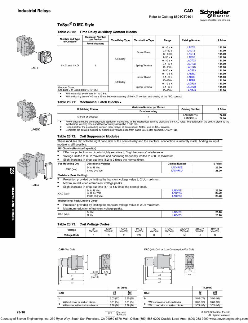
CAD (Vac Coil) CAD (Vdc Coil) or (Low Consumption Vdc Coil)
in. (mm) in. (mm)
CAD 3250
323503 CAD 32
50323503
b 3.03 (77) 3.90 (99) b 3.03 (77) 3.90 (99)
cWithout cover or add-on blocks 3.31 (84) 3.31 (84)
cWithout cover or add-on blocks 3.66 (93) 3.66 (93)
With cover, without add-on blocks 3.39 (86) 3.39 (86) With cover, without add-on blocks 3.74 (95) 3.74 (95)
LADT
LA6DK
LAD4
b
c
c1
c2
c3
1.770.49
(LAD-8)4512.5
b
c
c1
c2
c3
1.7745
I12 Discount Schedule
Courtesy of Steven Engineering, Inc.-230 Ryan Way, South San Francisco, CA 94080-6370-Main Office: (650) 588-9200-Outside Local Area: (800) 258-9200-www.stevenengineering.com
www.schneider-electric.us
23R
ELA
YS
AN
D T
IME
RS
© 2009 Schneider ElectricAll Rights Reserved
23-17
Industrial Relays CADRefer to Catalog 8501CT0101
TeSys® D IEC Style Relays
a For 24 V operation, the relay must be fitted with a 21 V coil (code Z7).
Table 23.74: Cabling AccessoryDescription Catalog Number $ Price
Mounting AdapterFor adapting existing wiring to a new product
Without coil suppression LAD4BB 23.00
With coil suppression24 to 48 Vac LAD4BBVE 23.0050 to 127 Vac LAD4BBVG 23.00110 to 250 Vac LAD4BBVU 23.00
Table 23.75: Electronic Serial Timer Modules a• Mounted using adaptor LAD4BB, to be ordered separately, see listing above.
On-delay Type
Operational Voltage Time Delay Catalog Number $ Price
24 to 250 Vac0.1 to 2 s LA4DT0U 82.001.5 to 30 s LA4DT2U 82.0025 to 500 s LA4DT4U 82.00
Table 23.76: Auto-Man-Stop Control Modules For local override operation tests with two-position “Auto-Man” switch and “O-I” switch
• Mounted using adaptor LAD4BB, to be ordered separately, see listing above.
Operational Voltage Catalog Number $ Price
24 to 100 Vac LA4DMK 35.00
Table 23.77: Accessories (ordered separately)For Connection
Description For Mounting On: Must be Ordered in Multiples of: Catalog Number $ Price ea.
For Marking
Sheet of 64 self-adhesive blank labels 8 x 33 CAD, LAD (4 contacts), LA6DK 10 LAD21 5.20Sheet of 112 self-adhesive blank labels 8 x 12 LAD (2 contacts), LADT 10 LAD22 5.20
For Protection
Lockout cover LADT, LADR 1 LA9D901 5.50Relay cover preventing access to the moving contact carrier CAD 1 LAD9ET1 5.20
Table 23.78: Application Data
Type CAD (Vac) CAD (Vdc) CAD (Vdc) Low Consumption
Rated Insulation Voltage (Ui)Conforming to IEC 60947-1-1Overvoltage category III and degree of pollution 3 690 V 690 V 690 V
Conforming to UL, CSA 600 V 600 V 600 VRated Impulse Withstand Voltage (Uimp) Conforming to IEC 60947-1-1 6 kV 6 kV 6 kV
Separation of Electrical Circuits To IEC 536 and VDE 0106 Reinforced insulation up to 400 V
Conforming to Standards IEC 60947-1-1, N-F C 63-140, VDE 0660, BS 4794.EN 60947-5-15
Approvals
UL: File: E164353CSA: File: LR43364 CE
CCN: NKCRClass: 3211 03
Protective Treatment Conforming to IEC 68 “TH” (Tropical Finish). See page 23 of Catalog 8501CT0101 for details.
Degree of Protection Conforming to VDE 0106 Front face protected against direct finger contact IP 2X
Protection against direct finger contact
I12 Discount Schedule
Courtesy of Steven Engineering, Inc.-230 Ryan Way, South San Francisco, CA 94080-6370-Main Office: (650) 588-9200-Outside Local Area: (800) 258-9200-www.stevenengineering.com
www.schneider-electric.us
23R
EL
AY
S A
ND
TIM
ER
S
23-18 © 2009 Schneider ElectricAll Rights Reserved
Industrial Relays CA2K and CA3KRefer to Catalog 8501CT0101
TeSys® K IEC Style Relays
a Complete catalog number by adding proper voltage code from Table 23.81 or Table 23.82 (for example, CA2KN40G7).
a Complete catalog number by adding proper voltage code from Table 23.83 (for example, CA4KN40BW3).
Approvals:
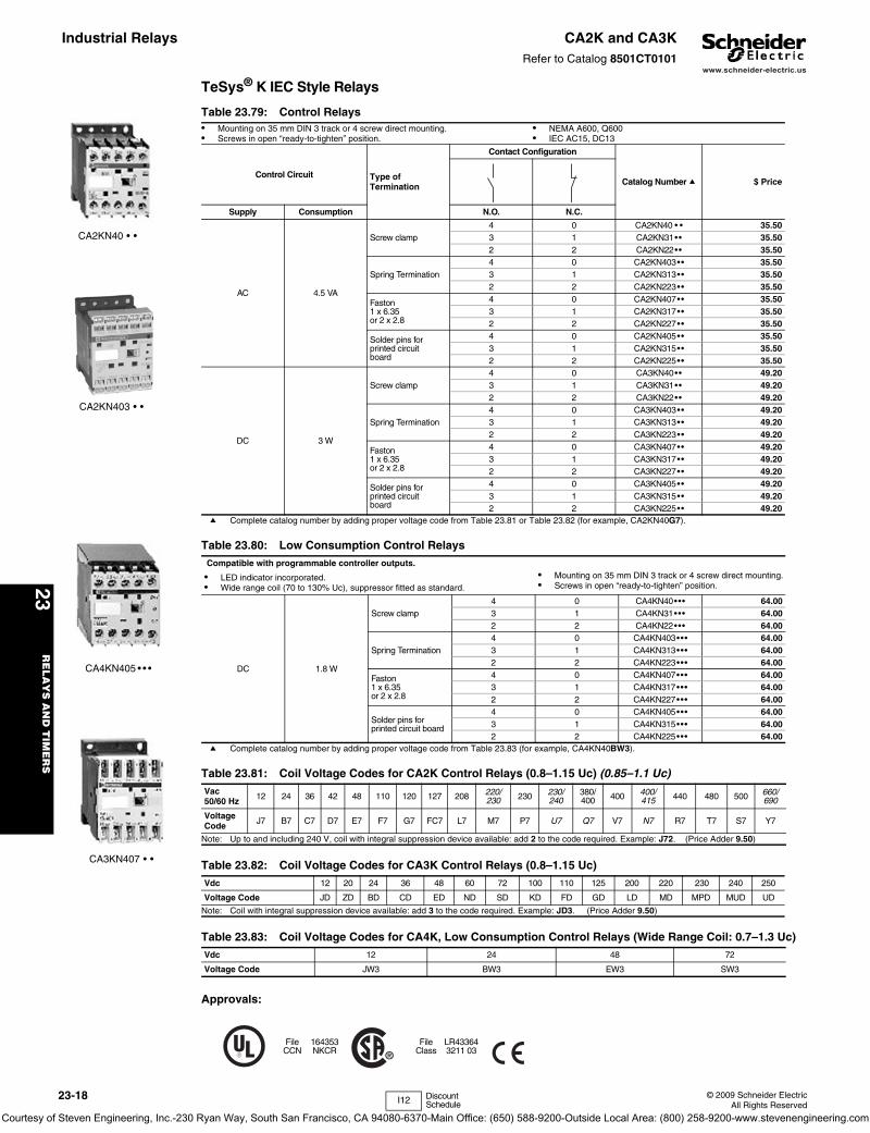
Table 23.79: Control Relays• Mounting on 35 mm DIN 3 track or 4 screw direct mounting. • Screws in open “ready-to-tighten” position.
• NEMA A600, Q600• IEC AC15, DC13
Control Circuit Type of Termination
Contact Configuration
Catalog Number a $ Price
Supply Consumption N.O. N.C.
AC 4.5 VA
Screw clamp4 0 CA2KN40 • • 35.503 1 CA2KN31•• 35.502 2 CA2KN22•• 35.50
Spring Termination4 0 CA2KN403•• 35.503 1 CA2KN313•• 35.502 2 CA2KN223•• 35.50
Faston 1 x 6.35 or 2 x 2.8
4 0 CA2KN407•• 35.503 1 CA2KN317•• 35.502 2 CA2KN227•• 35.50
Solder pins for printed circuitboard
4 0 CA2KN405•• 35.503 1 CA2KN315•• 35.502 2 CA2KN225•• 35.50
DC 3 W
Screw clamp4 0 CA3KN40•• 49.203 1 CA3KN31•• 49.202 2 CA3KN22•• 49.20
Spring Termination4 0 CA3KN403•• 49.203 1 CA3KN313•• 49.202 2 CA3KN223•• 49.20
Faston 1 x 6.35 or 2 x 2.8
4 0 CA3KN407•• 49.203 1 CA3KN317•• 49.202 2 CA3KN227•• 49.20
Solder pins for printed circuit board
4 0 CA3KN405•• 49.203 1 CA3KN315•• 49.202 2 CA3KN225•• 49.20
Table 23.80: Low Consumption Control Relays Compatible with programmable controller outputs.
• LED indicator incorporated. • Wide range coil (70 to 130% Uc), suppressor fitted as standard.
• Mounting on 35 mm DIN 3 track or 4 screw direct mounting.• Screws in open “ready-to-tighten” position.
DC 1.8 W
Screw clamp4 0 CA4KN40••• 64.003 1 CA4KN31••• 64.002 2 CA4KN22••• 64.00
Spring Termination4 0 CA4KN403••• 64.003 1 CA4KN313••• 64.002 2 CA4KN223••• 64.00
Faston 1 x 6.35 or 2 x 2.8
4 0 CA4KN407••• 64.003 1 CA4KN317••• 64.002 2 CA4KN227••• 64.00
Solder pins for printed circuit board
4 0 CA4KN405••• 64.003 1 CA4KN315••• 64.002 2 CA4KN225••• 64.00
Table 23.81: Coil Voltage Codes for CA2K Control Relays (0.8–1.15 Uc) (0.85–1.1 Uc)Vac50/60 Hz 12 24 36 42 48 110 120 127 208 220/
230 230 230/ 240
380/ 400 400 400/
415 440 480 500 660/ 690
Voltage Code J7 B7 C7 D7 E7 F7 G7 FC7 L7 M7 P7 U7 Q7 V7 N7 R7 T7 S7 Y7
Note: Up to and including 240 V, coil with integral suppression device available: add 2 to the code required. Example: J72. (Price Adder 9.50)
Table 23.82: Coil Voltage Codes for CA3K Control Relays (0.8–1.15 Uc)Vdc 12 20 24 36 48 60 72 100 110 125 200 220 230 240 250
Voltage Code JD ZD BD CD ED ND SD KD FD GD LD MD MPD MUD UD
Note: Coil with integral suppression device available: add 3 to the code required. Example: JD3. (Price Adder 9.50)
Table 23.83: Coil Voltage Codes for CA4K, Low Consumption Control Relays (Wide Range Coil: 0.7–1.3 Uc)Vdc 12 24 48 72
Voltage Code JW3 BW3 EW3 SW3
FileCCN
164353NKCR
FileClass
LR433643211 03
CA2KN40 • •
CA3KN407 • •
CA2KN403 • •
CA4KN405 • • •
I12 Discount Schedule
Courtesy of Steven Engineering, Inc.-230 Ryan Way, South San Francisco, CA 94080-6370-Main Office: (650) 588-9200-Outside Local Area: (800) 258-9200-www.stevenengineering.com

www.schneider-electric.us
23R
ELA
YS
AN
D T
IME
RS
© 2009 Schneider ElectricAll Rights Reserved
23-19
Industrial Relays CA2K and CA3KRefer to Catalog 8501CT0101
TeSys® K IEC Style Relays
a Not to be used on CA4KN relays.b Clip-on front mounting, 1 block per control relay.c Auxiliary contact module not suitable for safety circuits.
Note: For other electronic timers see Type RE7 and 9050 Type JCK, pages 23-28 and 23-29.
d Protection by the limitation of the transient voltage to 2 Uc maximum. Maximum reduction of the transient voltage peaks. Slight time delay on drop-out (1.1 to 1.5 times normal).
e No overvoltage or oscillation frequency. Polarized component. Slight time delay on drop-out (1.1 to 1.5 times normal).
f Protection by limitation of the transient voltage to 3 Uc max. and limitation of the oscillation frequency. Slight time delay on drop-out (1.2 times to twice normal).
g See “Clip-in Marker Strips” in Catalog 8501CT0101 for information on completing the catalog number.
Table 23.84: Instantaneous Auxiliary Contact Blocks bcClip-on Front Mounting, 1 Block Per Control Relay
Type of Connection
Contact Configuration
Catalog Number $ Price
N.O. N.C.
Screw Clamp
2 0 LA1KN20 14.200 2 LA1KN02 14.201 1 LA1KN11 14.204 0 LA1KN40a 27.303 1 LA1KN31a 27.302 2 LA1KN22a 27.301 3 LA1KN13a 27.300 4 LA1KN04a 27.30
Spring Termination
2 0 LA1KN203 14.201 1 LA1KN113 14.200 2 LA1KN023 14.204 0 LA1KN403a 27.303 1 LA1KN313a 27.302 2 LA1KN223a 27.301 3 LA1KN133a 27.300 4 LA1KN043a 27.30
Faston 1 x 6.35 or 2 x 2.8
2 0 LA1KN207 14.200 2 LA1KN027 14.201 1 LA1KN117 14.204 0 LA1KN407a 27.303 1 LA1KN317a 27.302 2 LA1KN227a 27.301 3 LA1KN137a 27.300 4 LA1KN047a 27.30
Table 23.85: Electronic Time Delay Contact BlocksRelay output, with common point changeover contact 240 Vac/Vdc, 2 A maximum
Control voltage 0.85–1.1 Uc
Maximum switching capacity 250 VA or 150 W
Operating temperature –10 to + 60oC (+14o F to 140o F)
Reset time 1.5 s during the time delay period, 0.5 s after the time delay.
Table 23.86: Clip-on front mounting, 1 block per control RelayVoltage (V) Type Timing Range, s Composition C.O. Catalog No. $ Price
AC or DC / 24 to 48On-delay 1 to 30 1
LA2KT2E32.80
AC / 110 to 240 LA2KT2U
Table 23.87: Accessories (supplied separately)
Description Sold in lots of Catalog No. $ Price ea.
Marker holderg Clips on front of relay 100 LA9D90 0.06
Clip-on markersg
4 maximum per device
Strip of 10 identical numbers, 0 to 925
AB1R•g0.70
Strip of 10 identical capital letters A to Z AB1G•g
Suppressor modules with incorporated LED indicator
Clips onto front of relay with locating device. No tools required for connection.
For AC and DC voltages 12 to 24 V (varistor)
5
LA4KE1Bd
9.80
For AC and DC voltages 32 to 48 V (varistor) LA4KE1Ed
For AC and DC voltages 50 to 129 V (varistor) LA4KE1FCd
For AC and DC voltages 130 to 250 V (varistor) LA4KE1UG d
For DC voltages 12 to 24 V (diode + Zener diode) LA4KC1Be
For DC voltages 32 to 48 V (diode + Zener diode) LA4KC1Ee
For AC voltages 220 to 250 V (RC) LA4KA1Uf
LA1KN20 LA1KN40
LA1KN403
38
27
1.45
1.06
57
LA2KT
58
341.34 2.24
2.28
341.34
LA2KT electronic time delay contact blocks
5731
LA1-K
58 50=
=
35
45
= =
4xØ4
2.28
1.22 2.24 1.38
1.77
1.97
On panel
Approximate dimensions for CA2, CA3, CA4K control relays
C Product
in. mm
2.22 59 AM1DP2002.60 66 AM1DE200
50
53
45
58
8.65= = =
10xØ1.3
A1
A2
2.28
2.05
1.97
1.77
0.34
58
45C 1.77
2.28
On printed circuit board
n AM1DP200 or AM1DE200 mounting rail—35 mm DIN rail (see page 22-16 for additional DIN rail)
in.mm
Table 23.88: EnvironmentConforming to Standards IEC 947, NF C 63-140, VDE 0660, BS 5424, CE
Approvals UL, CSA, DEMKO, NEMKO, SEMKO, FI
Protective treatment Conforming to IEC 68 (DIN 50016) “TC” (Climateproof)
Degree of protection Conforming to VDE 0106 Protection against direct finger contact
Ambient air temperature Storage -58 to 176 oF (-50 to 80oC)Operation -13 to 122 oF (-25 to 50oC)
Maximum operating altitude Without derating 6562 ft (2000 m)
I12 Discount Schedule
Courtesy of Steven Engineering, Inc.-230 Ryan Way, South San Francisco, CA 94080-6370-Main Office: (650) 588-9200-Outside Local Area: (800) 258-9200-www.stevenengineering.com

www.schneider-electric.us
23R
EL
AY
S A
ND
TIM
ER
S
23-20 © 2009 Schneider ElectricAll Rights Reserved
Industrial Relays CA2SK and CA3SKRefer to Catalog 8501CT0101
TeSys® SK IEC Style Relays
a Use the appropriate voltage code to complete the catalog number (for example: CA2SK11G7)
Transient Suppressor ModuleDampens the voltage spike that may occur when the relay coil is de-energized. The spike may adversely affect solid state equipment near the relay. The transient suppressor module snaps into a cavity located in the side of the relay. These modules can be used with CA2SK and CA3SK relays.
b Alternating relays CA2SKE available in these voltages only. No other voltages are available.
Alternating Relays, CA2SKERefer to Catalog 8501CT9701
These alternating relays are used to alternate the use of 2 motor circuits. When the coil is energized the first time, one contact closes and will open when the coil is de-energized. When the coil is energized again, the other contact will close and will open when the coil is de-energized. The contacts from these alternators are to be used in the control circuit of the starters that are controlling pump or compressor motors. Approvals: UL File: E164353 CCN: NKCR; CSA File: LR43364 Class: 3211 03.
a Use the appropriate voltage code to complete the catalog number (for example, CAZSK11G7). Only available with voltages indicated above.
Table 23.89: IEC Style Industrial Control Relays• Miniature size saves space.• Mounts on 35 mm DIN 3 track• Up to 4 poles.
Control Circuit Supply Consumption Type of TerminationContact Configuration
Catalog Number $ PriceN.O. N.C.
AC 4.2 VAScrew clamp
1 1 CA2SK11•• a43.70
2 0 CA2SK20•• a
DC 2.2 W1 1 CA3SK11•• a
51.002 0 CA3SK20•• a
Table 23.90: Contact Adder Decks (for CA2SK20 only)
Type of TerminationContact Configuration
Catalog Number $ PriceN.O. N.C.
Screw clamp2 0 LA1SK20
16.901 1 LA1SK110 2 LA1SK02
Table 23.91: Transient Suppressor ModuleControl Circuit Voltage Catalog Number $ Price
24–48 Vac 50/60 Hz, 24–48 Vdc LA4SKEIE21.80
110–250 Vac 50/60 Hz, 110–250 Vdc LA4SKEIU
Table 23.92: Coil Voltage Codes for Control RelaysVoltage 12 24 36 48 72 110 120 220 230 240 380 400 480
50/60 Hz — B7 b — E7 b — F7 G7 b M7 b P7 U7 b Q7 V7 T7 bDC JD BD CD ED SD — — — — — — — —
Table 23.93: Alternating RelaysCoil Voltage(Voltage-Hz) Type $ Price
24–50/60 CA2SKE20••a 120.00
Table 23.94: Contact Ratings for CA2SK, CA3SK, AND CA2SKE20 RelaysAC DC
Volts
Inductive 35% PF Resistive 75% PF
Volts Continuous AmperesNEMA Rating
Make Break Continuous Amperes
Make, Break and Continuos AmperesA VA A VA
120
A600
60
7200
6
720 10 10
24 3240 30 3 60 2480 15 1.5 110 0.8600 12 1.2 240 0.2
Approximate Dimensions for CA2SKE Relay
CA2SK11G7
LA1SK11
CA2SKE20
2.20 56
1.0627
2.1956
.205
.144 Dual Dimensions: INCHES
Millimeters
#8or
(49)1.93
(34.5)1.36
(68)2.68
(45)1.77
(58)2.28
(4).16
4mm
I12 Discount Schedule
Approvals:
FileCCN
E164353NKCR
FileClass
LR433643211 03
Courtesy of Steven Engineering, Inc.-230 Ryan Way, South San Francisco, CA 94080-6370-Main Office: (650) 588-9200-Outside Local Area: (800) 258-9200-www.stevenengineering.com

www.schneider-electric.us
23R
ELA
YS
AN
D T
IME
RS
© 2009 Schneider ElectricAll Rights Reserved
23-21
Industrial RelaysSquare D® NEMA Style
Type X® RelaysClass 8501 / Refer to Catalog 8501CT9601
AC Control Relays• Straight-through wiring• Plug-in contact cartridges for easy contact conversion and
replacement• Contact conversion without removing terminal screws or wires• Self-lifting pressure wire connectors• Replaceable coil
a A maximum of 8 N.C. contacts is allowed on 9–12 pole relays.
AC Master Relays• 20 ampere contact rating due to use of master contact
cartridges. d• Provisions for standard cartridges to be used in contact
cavities not occupied by master cartridges in 2-8 pole AC relay.
b Attachments not permitted on this relay.
AC Timing Relays• Easily convertible On Delay or Off Delay• Two adjustable timing ranges• Repeat accuracy well above ±10%• Convertible 1 N.O. and 1 N.C. timed contacts• Large knob for easy adjustment of time delay• Off Delay mode times out even after loss of power.
AC Latching Relays• Mechanical latch holds all contacts switched even after
removal of power from replaceable latching coil.• Provides sequence memory in the event of power loss. Ideal
for press control, process control and punch presses.• Replaceable unlatch coil to switch contacts back to original
state.
c Voltage Code must be specified to order these products. Refer to Table 23.101 and insert the code as shown in Table 23.104: How to Order.
Approvals:
d Maximum of six 8501 Type XC4 Master Cartridges may be used on only 7 and 8 pole AC Devices
AC Control Relays and AC Master Relays
AC Latching Relay Dimensions
For replacement coils, see page 23-23.
Table 23.95: AC Control Relays
Normally Open ConvertibleInstantaneous Contacts
Control Relay a
Typec $ Price
023468
1012
XO00XO20XO30XO40XO60XO80
XO1000XO1200
116.00171.00201.00228.00286.50312.00399.00458.00
Table 23.96: AC Master Relays
Number of N.O. 20 Ampere Convertible Contacts
Open Typeb
Typec $ Price
246
XMO20XMO40XMO60
257.00399.00543.00
Table 23.97: AC Timing Relays
Timing Mode
N.O.Convertible Instantaneous Contacts
Timed Convertible
Contacts
Timing Relay
$ Price0.2–60 s 5–180 s
N.O. N.C. Typec Typec
On Delay
024
111
111
XO00XTE1XO20XTE1XO40XTE1
XO00XTE2XO20XTE2XO40XTE2
513.00570.00629.00
Off Delay
024
111
111
XO00XTD1XO20XTD1XO40XTD1
XO00XTD2XO20XTD2XO40XTD2
513.00570.00629.00
Table 23.98: AC Latching Relays
N.O. Convertible Instantaneous Contacts
Latching Relay
Typec $ Price
23468
XO20XLXO30XLXO40XLXO60XLXO80XL
372.00399.00428.00485.00543.00
FileCCN
E78403NKCR
FileClass
0609053211 03
IEC 60947-1
Type XMO40Control Relay
Type XMO40Master Relay
Type XO40XTE1Timing Relay
Type XO40XLLatching Relay
Table 23.99: AC Contact Ratings (for DC ratings, see page 23-22)
Type of Cartridge V
Inductive35% Power Factor
Resistive75% Power Factor
NEMARating
Make BreakContinuous
Amperes
Make, Break and Continuous Amperes
A VA A VA
Standardor
Overlapping
120240480600
A600
60301512
7200
63
1.51.2
720 10 10
Masterd — A600 Same as standard cartridge above except substitute 20 A for the continuous ampere rating
Logic Reed — — 150 Vac, 150 mA, 8 W Maximum
Table 23.100: Average Operating Time (ms)Device Pick-Up Drop-Out
AC Relay 15 16AC Latching Relay 15 13
Table 23.101: Voltage CodesAC Voltages - Hz Code
12–6024–6024–5048–6048–50120–60/110–50208–60240–60/220–50277–60480–60/440–50600–60/550–50
V11V01V12V18V16V02V08V03V04V06V07
Table 23.102: Dimensions and Weight
No. of PolesDim. A
Shipping Weight, lbin. mm
0–4 3.95 100 2.06–8 5.16 131 2.3
10–12 6.36 162 2.7
Table 23.103: Dimensions and Weight
No. ofPoles Dim. A
Shipping Weight, lbin. mm
2–4 6.54 166 2.86–8 7.74 197 3.1
Table 23.104: How to OrderTo Order Specify: Catalog Number
• Class Number• Type Number• Voltage Code
Class Type Voltage Code
8501 XO40 V02
.195
2.23571.12
28
3.5089
3.1279
Prov. for(2) #8/#10 Mtg. Screws
B30080-064
A
Dual Dimensions: INCHESMillimeters
A.195
2.2357
1.1228
3.1279
3.5089 Dual Dimensions: INCHES
Millimeters
CP1 Discount Schedule
Courtesy of Steven Engineering, Inc.-230 Ryan Way, South San Francisco, CA 94080-6370-Main Office: (650) 588-9200-Outside Local Area: (800) 258-9200-www.stevenengineering.com
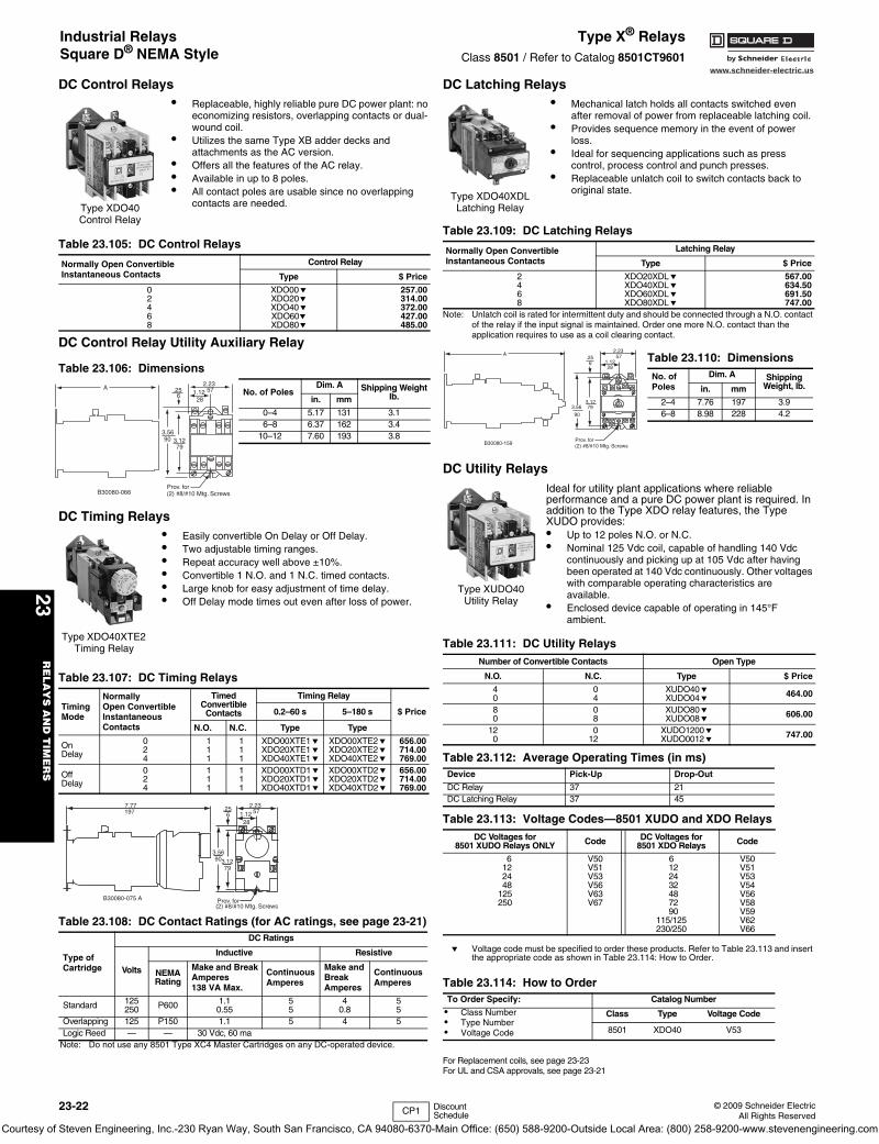
www.schneider-electric.us
23R
EL
AY
S A
ND
TIM
ER
S
23-22 © 2009 Schneider ElectricAll Rights Reserved
DC Control Relays
DC Control Relay Utility Auxiliary Relay
DC Timing Relays
DC Latching Relays
Note: Unlatch coil is rated for intermittent duty and should be connected through a N.O. contact of the relay if the input signal is maintained. Order one more N.O. contact than the application requires to use as a coil clearing contact.
DC Utility Relays
e Voltage code must be specified to order these products. Refer to Table 23.113 and insert the appropriate code as shown in Table 23.114: How to Order.
For Replacement coils, see page 23-23For UL and CSA approvals, see page 23-21
• Replaceable, highly reliable pure DC power plant: no economizing resistors, overlapping contacts or dual-wound coil.
• Utilizes the same Type XB adder decks and attachments as the AC version.
• Offers all the features of the AC relay.• Available in up to 8 poles.• All contact poles are usable since no overlapping
contacts are needed.
Table 23.105: DC Control Relays
Normally Open ConvertibleInstantaneous Contacts
Control Relay
Type $ Price
02468
XDO00eXDO20eXDO40eXDO60eXDO80e
257.00314.00372.00427.00485.00
Table 23.106: Dimensions
No. of PolesDim. A Shipping Weight
lb.in. mm
0–4 5.17 131 3.16–8 6.37 162 3.4
10–12 7.60 193 3.8
• Easily convertible On Delay or Off Delay.• Two adjustable timing ranges.• Repeat accuracy well above ±10%.• Convertible 1 N.O. and 1 N.C. timed contacts.• Large knob for easy adjustment of time delay.• Off Delay mode times out even after loss of power.
Table 23.107: DC Timing Relays
TimingMode
NormallyOpen ConvertibleInstantaneous Contacts
TimedConvertible
Contacts
Timing Relay
$ Price0.2–60 s 5–180 s
N.O. N.C. Type Type
OnDelay
024
111
111
XDO00XTE1eXDO20XTE1eXDO40XTE1e
XDO00XTE2eXDO20XTE2eXDO40XTE2e
656.00714.00769.00
OffDelay
024
111
111
XDO00XTD1eXDO20XTD1eXDO40XTD1e
XDO00XTD2eXDO20XTD2eXDO40XTD2e
656.00714.00769.00
Table 23.108: DC Contact Ratings (for AC ratings, see page 23-21)
Type ofCartridge
DC Ratings
Volts
Inductive Resistive
NEMARating
Make and Break Amperes138 VA Max.
Continuous Amperes
Make and Break Amperes
Continuous Amperes
Standard 125250 P600 1.1
0.5555
40.8
55
Overlapping 125 P150 1.1 5 4 5Logic Reed — — 30 Vdc, 60 ma
Note: Do not use any 8501 Type XC4 Master Cartridges on any DC-operated device.
Type XDO40 Control Relay
A .256
2.23571.12
28
3.5690 3.12
79
Prov. for(2) #8/#10 Mtg. ScrewsB30080-066
Type XDO40XTE2 Timing Relay
7.77197 .25
6
2.23571.12
28
3.56903.12
79
Prov. for(2) #8/#10 Mtg. Screws
B30080-075 A
• Mechanical latch holds all contacts switched even after removal of power from replaceable latching coil.
• Provides sequence memory in the event of power loss.
• Ideal for sequencing applications such as press control, process control and punch presses.
• Replaceable unlatch coil to switch contacts back to original state.
Table 23.109: DC Latching Relays
Normally Open ConvertibleInstantaneous Contacts
Latching Relay
Type $ Price
2468
XDO20XDLeXDO40XDLeXDO60XDLeXDO80XDLe
567.00634.50691.50747.00
Table 23.110: Dimensions
No. ofPoles
Dim. A ShippingWeight, lb.in. mm
2–4 7.76 197 3.96–8 8.98 228 4.2
Ideal for utility plant applications where reliable performance and a pure DC power plant is required. In addition to the Type XDO relay features, the Type XUDO provides:• Up to 12 poles N.O. or N.C.• Nominal 125 Vdc coil, capable of handling 140 Vdc
continuously and picking up at 105 Vdc after having been operated at 140 Vdc continuously. Other voltages with comparable operating characteristics are available.
• Enclosed device capable of operating in 145°F ambient.
Table 23.111: DC Utility RelaysNumber of Convertible Contacts Open Type
N.O. N.C. Type $ Price
40
04
XUDO40eXUDO04e 464.00
80
08
XUDO80eXUDO08e 606.00
120
012
XUDO1200eXUDO0012e 747.00
Table 23.112: Average Operating Times (in ms)Device Pick-Up Drop-Out
DC Relay 37 21DC Latching Relay 37 45
Table 23.113: Voltage Codes—8501 XUDO and XDO RelaysDC Voltages for
8501 XUDO Relays ONLY Code DC Voltages for 8501 XDO Relays Code
6122448
125250
V50V51V53V56V63V67
6122432487290
115/125230/250
V50V51V53V54V56V58V59V62V66
Table 23.114: How to OrderTo Order Specify: Catalog Number
• Class Number• Type Number • Voltage Code
Class Type Voltage Code
8501 XDO40 V53
Type XDO40XDL Latching Relay
A.256
2.2357
1.1228
3.56
90
3.1279
Prov. for(2) #8/#10 Mtg. ScrewsB30080-159
Type XUDO40 Utility Relay
CP1 Discount Schedule
Industrial RelaysSquare D® NEMA Style
Type X® RelaysClass 8501 / Refer to Catalog 8501CT9601
Courtesy of Steven Engineering, Inc.-230 Ryan Way, South San Francisco, CA 94080-6370-Main Office: (650) 588-9200-Outside Local Area: (800) 258-9200-www.stevenengineering.com
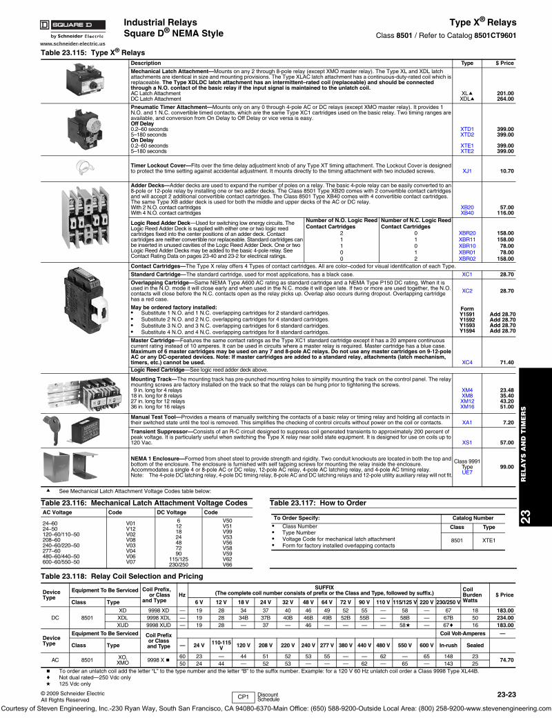
www.schneider-electric.us
23R
ELA
YS
AN
D T
IME
RS
© 2009 Schneider ElectricAll Rights Reserved
23-23
a See Mechanical Latch Attachment Voltage Codes table below:
b To order an unlatch coil add the letter “L” to the type number and the letter “B” to the suffix number. Example: for a 120 V 60 Hz unlatch coil order a Class 9998 Type XL44B. c Not dual rated—250 Vdc onlyd 125 Vdc only
Table 23.115: Type X® RelaysDescription Type $ Price
Mechanical Latch Attachment—Mounts on any 2 through 8-pole relay (except XMO master relay). The Type XL and XDL latch attachments are identical in size and mounting provisions. The Type XLAC latch attachment has a continuous-duty-rated coil which is replaceable. The Type XDLDC latch attachment has an intermittent–rated coil (replaceable) and should be connected through a N.O. contact of the basic relay if the input signal is maintained to the unlatch coil.AC Latch AttachmentDC Latch Attachment
XLaXDLa
201.00264.00
Pneumatic Timer Attachment—Mounts only on any 0 through 4-pole AC or DC relays (except XMO master relay). It provides 1 N.O. and 1 N.C. convertible timed contacts, which are the same Type XC1 cartridges used on the basic relay. Two timing ranges are available, and conversion from On Delay to Off Delay or vice versa is easy.Off Delay 0.2–60 seconds5–180 secondsOn Delay 0.2–60 seconds5–180 seconds
XTD1XTD2
XTE1XTE2
399.00399.00
399.00399.00
Timer Lockout Cover—Fits over the time delay adjustment knob of any Type XT timing attachment. The Lockout Cover is designed to protect the time setting against accidental adjustment. It mounts directly to the timing attachment with two included screws. XJ1 10.70
Adder Decks—Adder decks are used to expand the number of poles on a relay. The basic 4-pole relay can be easily converted to an 8-pole or 12-pole relay by installing one or two adder decks. The Class 8501 Type XB20 comes with 2 convertible contact cartridges and will accept 2 additional convertible contact cartridges. The Class 8501 Type XB40 comes with 4 convertible contact cartridges. The same Type XB adder deck is used for both the middle and upper decks of the AC or DC relay.With 2 N.O. contact cartridgesWith 4 N.O. contact cartridges
XB20XB40
57.00116.00
Logic Reed Adder Deck—Used for switching low energy circuits. The Logic Reed Adder Deck is supplied with either one or two logic reed cartridges fixed into the center positions of an adder deck. Contact cartridges are neither convertible nor replaceable. Standard cartridges can be inserted in unused cavities of the Logic Reed Adder Deck. One or two Logic Reed Adder Decks may be added to the basic 4-pole relay. See Contact Rating Data on pages 23-40 and 23-2 for electrical ratings.
Number of N.O. Logic Reed Number of N.C. Logic Reed Contact Cartridges Contact Cartridges
2 0 XBR20 158.001 1 XBR11 158.001 0 XBR10 78.000 1 XBR01 78.000 2 XBR02 158.00
Contact Cartridges—The Type X relay offers 4 Types of contact cartridges. All are color–coded for visual identification of each Type.
Standard Cartridge—The standard cartridge, used for most applications, has a black case. XC1 28.70
Overlapping Cartridge—Same NEMA Type A600 AC rating as standard cartridge and a NEMA Type P150 DC rating. When it is used in the N.O. mode it will close early and when used in the N.C. mode it will open late. If two or more are used together, the N.O. contacts will close before the N.C. contacts open as the relay picks up. Overlap also occurs during dropout. Overlapping cartridge has a red case.
XC2 28.70
May be ordered factory installed:• Substitute 1 N.O. and 1 N.C. overlapping cartridges for 2 standard cartridges.• Substitute 2 N.O. and 2 N.C. overlapping cartridges for 4 standard cartridges. • Substitute 3 N.O. and 3 N.C. overlapping cartridges for 6 standard cartridges.• Substitute 4 N.O. and 4 N.C. overlapping cartridges for 8 standard cartridges.
FormY1591Y1592Y1593Y1594
Add 28.70Add 28.70Add 28.70Add 28.70
Master Cartridge—Features the same contact ratings as the Type XC1 standard cartridge except it has a 20 ampere continuous current rating instead of 10 amperes. It can be used in circuits where a master relay is required. Master cartridge has a blue case. Maximum of 6 master cartridges may be used on any 7 and 8-pole AC relays. Do not use any master cartridges on 9-12-pole AC or any DC-operated devices. Note: If master cartridges are added to a standard relay, attachments (latch mechanism, timers, etc.) cannot be used. XC4 71.40Logic Reed Cartridge—See logic reed adder deck above.
Mounting Track—The mounting track has pre-punched mounting holes to simplify mounting the track on the control panel. The relay mounting screws are factory installed on the track so that the relays can be hung prior to tightening the screws.9 in. long for 4 relays
18 in. long for 8 relays27 in. long for 12 relays36 in. long for 16 relays
XM4XM8XM12XM16
23.4835.4043.2051.00
Manual Test Tool—Provides a means of manually switching the contacts of a basic relay or timing relay and holding all contacts in their switched state until the tool is removed. This simplifies the checking of control circuits without power on the coil or contacts. XA1 7.20
Transient Suppressor—Consists of an R-C circuit designed to suppress coil generated transients to approximately 200 percent of peak voltage. It is particularly useful when switching the Type X relay near solid state equipment. It is designed for use on coils up to 120 Vac. XS1 57.00
NEMA 1 Enclosure—Formed from sheet steel to provide strength and rigidity. Two conduit knockouts are located in both the top and bottom of the enclosure. The enclosure is furnished with self tapping screws for mounting the relay inside the enclosure. Accommodates a single 4 or 8-pole AC or DC relay, 12-pole AC relay, 4-pole AC latching relay, and 4-pole AC timing relay. Note: The 4-pole DC latching relay, 4-pole DC timing relay, 8-pole AC and DC latching relays and 12-pole utility auxiliary relay will not fit.
Class 9991Type UE7
99.00
Table 23.116: Mechanical Latch Attachment Voltage Codes Table 23.117: How to OrderAC Voltage Code DC Voltage Code
24–6024–50120–60/110–50208–60240–60/220–50277–60480–60/440–50600–60/550–50
V01V12V02V08V03V04V06V07
6121824487290
115/125230/250
V50V51V99V53V56V58V59V62V66
Table 23.118: Relay Coil Selection and Pricing
DeviceType
Equipment To Be Serviced Coil Prefix,or Class
and TypeHz
SUFFIX(The complete coil number consists of prefix or the Class and Type, followed by suffix.)
CoilBurdenWatts
$ PriceClass Type 6 V 12 V 18 V 24 V 32 V 48 V 64 V 72 V 90 V 110 V 115/125 V 220 V 230/250 V
DC 8501XD 9998 XD — 19 28 34 37 40 46 49 52 55 — 58 — 67 18 183.00XDL 9998 XDL — 19 28 34B 37B 40B 46B 49B 52B 55B — 58B — 67B 50 234.00XUD 9998 XUD — 19 28 — 37 — 46 — — — — 58d — 67c 16 183.00
DeviceType
Equipment To Be Serviced Coil Prefixor Classand Type
Coil Volt-Amperes —
Class Type — 24 V 110-115 V 120 V 208 V 220 V 240 V 277 V 380 V 440 V 480 V 550 V 600 V In-rush Sealed
AC 8501 XO, XMO 9998 X b
60 23 — 44 51 52 53 55 — — 62 — 65 148 2374.70
50 24 44 — 52 53 — — — 62 — 65 — 143 25
To Order Specify: Catalog Number
• Class Number• Type Number• Voltage Code for mechanical latch attachment• Form for factory installed overlapping contacts
Class Type
8501 XTE1
CP1 Discount Schedule
Industrial RelaysSquare D® NEMA Style
Type X® RelaysClass 8501 / Refer to Catalog 8501CT9601
Courtesy of Steven Engineering, Inc.-230 Ryan Way, South San Francisco, CA 94080-6370-Main Office: (650) 588-9200-Outside Local Area: (800) 258-9200-www.stevenengineering.com

www.schneider-electric.us
23R
EL
AY
S A
ND
TIM
ER
S
23-24 © 2009 Schneider ElectricAll Rights Reserved
Timers RE11/RE48/REXLRefer to Catalog 9050CT0001
Zelio ® IEC Style—17.9 mm wideTable 23.119: RE11 Modular Timers—17.9 mm wide (Multi-range timers offering 7 selectable ranges)Functions Supply Voltages Rated Current Catalog Number $ Price
Output 1 C/O contactOn delay 24 Vdc, 24–240 Vac 8A RE11RAMU 51.00Interval 24 Vdc, 24–240 Vac 8A RE11RHMU 51.00Asymmetrical repeat cycle 24 Vdc, 24–240 Vac 8A RE11RLMU 63.00Asymmetrical repeat cycle 12 Vac/Vdc 8A RE11RLJU 89.00One shot 24 Vdc, 24–240 Vac 8A RE11RBMU 62.00Off delay with control start 24 Vdc, 24–240 Vac 8A RE11RCMU 62.00Multi-function a 24 Vdc, 24–240 Vac 8A RE11RMMU 74.00Multi-function a 12–240 Vac/Vdc 8A RE11RMMW 89.00Multi-function a 12–240 Vac/Vdc 8A RE11RMMWS 89.00Multi-function a 12 Vac/Vdc 8A RE11RMJU 89.00Multi-function b 24 Vdc, 24–240 Vac 8A RE11RMEMU 89.00Multi-function a 24 Vdc, 24–240 Vac 8A RE11RMXMU 89.00a Timing ranges: 0.1–1 s, 1–10 s, 0.1–10 min, 1–10 min, 0.1–1 hr, 1–10 hr, 10–100 hrb Timing ranges: 0.1–1 s, 1–10 s, 0.1–10 min, 1–10 min, 0.1–1 hr, 1–10 hr
Conforming to standards IEC 61812-1, EN 50081-1/2, EN 50082-1/2, LV directives (73/23/EEC + 93/68/EEC (CE marking) +EMC directive (89/336/EEC + IEC 60669-2-3)
Approvals
cULus File: E173076 CNN: NRNTFile: E173076 CNN: NRNT7
CSA File: 217698 Class 3211 07CEGL except RE11 RMX MU and RE11 RME MU
Ambient air temperature around the device
Storage oF (oC) –22 to +140 (–30 to +60)Operation oF (oC) –4 to +140 (–20 to +60)
Table 23.120: RE11 Modular Timers—17.9 mm wide (Multi-function, dual function or single function)Functions Supply Voltages Rated Current Catalog Number $ Price
Solid state outputOn delay 24–240 Vac/Vdc 0.7A RE11LAMW 54.00Interval 24–240 Vac 0.7A RE11LHBM 51.00Off delay with control contact 24–240 Vac 0.7A RE11LCBM 62.00Asymmetrical repeat cycle 24–240 Vac 0.7A RE11LLBM 89.00Multi-function 24–240 Vac 0.7A RE11LMBM 74.00Timing ranges: 0.1–1 s, 1–10 s, 0.1–10 min, 1–10 min, 0.1–1 hr, 1–10 hr, 10–100 hr
Conforming to standards IEC 61812-1, EN 50081-1/2, EN 50082-1/2, LV directives (73/23/EEC + 93/68/EEC (CE marking) + EMC directive (89/336/EEC + IEC 60669-2-3)
cULus File: E173076 CNN: NRNT
Approvals File: E173076 CNN: NRNT7
CSA File: 217698 Class: 3211 07CE
Ambient air temperature around the device
Storage oF (oC) –22 to 140 (–30 to +60)Operation oF (oC) –4 to 140 (–20 to +60)
Table 23.121: RE48 Panel Mount Timers (For required socket, refer to the catalog section)Functions Supply Voltages Rated Current Catalog Number $ Price
Single function: on delay, two relay outputs 24–240 Vac/Vdc 2 x 5 A RE48ATM12MW 87.00Repeat cycle: two relay outputs 24–240 Vac/Vdc 2 x 5 A RE48ACV12MW 104.00Multi-function: on delay, one shot, off delay, repeat cycle 24–240 Vac/Vdc 2 x 5 A RE48AML12MW 102.00Multi-function: on delay and interval, two relay outputs, of which one selectable and instantaneous 24–240 Vac/Vdc 2 x 5A RE48AMH13MW 102.00
Conforming to standards IEC 61812-1, EN 50081-1/2, EM 50082-1/2, LV directives (73/23/EEC +93/68/EEC (CE marking) + ENC directive (89/336/EEC + IEC 60669-2-3)
Approvals
cURusFile: E173076 CNN: NRNT2File: E173076 CNN: NRNT8
CSA File: 217698 Class: 3211 07CE, C-Tick, GLRoHS compliant as of date code 0625
Ambient air temperature around the deviceStorage oF (oC) –40 to 158 (–40 to +70)
Operation oF (oC) –4 to 122 (–20 to +50)
Table 23.122: REXL Miniature Plug-in Timers (For required socket, refer to the catalog section)4 pole 2 pole
Function Supply Voltages RatedCurrent Catalog Number $ Price Rated
Current Catalog Number $ Price
Single function (On-Delay
12 Vdc 3A REXL4TMJD 66.00 5A REXL2TMJD 63.0024 Vdc c 3A REXL4TMBD 66.00 5A REXL2TMBD 63.00
24 Vac 50/60 Hz c 3A REXL4TMB7 66.00 5A REXL2TMB7 63.00120 Vac 50/60 Hz 3A REXL4TMF7 66.00 5A REXL2TMF7 63.00230 Vac 50/60 Hz 3A REXL4TMP7 66.00 5A REXL2TMP7 63.00
Timing Ranges 0.1–1 s, 1–10 s, 0.1–1 min, 1–10 min, 0.1–1 hr, 1–10 hr, 10–100 hrFor 48 Vac supply, additional resistor 390 ohm 4 W / 24 Vc For 48 Vac supply, additional resistor 560 ohm 2 W / 24 V
Approvals: FileCCN
FileCCN
E173076NRNT2
E173076NRNT8
FileClass
217698321107 IEC 61812-1 RoHS
Compliantas of date code 0625
RE11RLMU
RE11LHBM
RE48A TM12MW
CP1 Discount Schedule
Courtesy of Steven Engineering, Inc.-230 Ryan Way, South San Francisco, CA 94080-6370-Main Office: (650) 588-9200-Outside Local Area: (800) 258-9200-www.stevenengineering.com
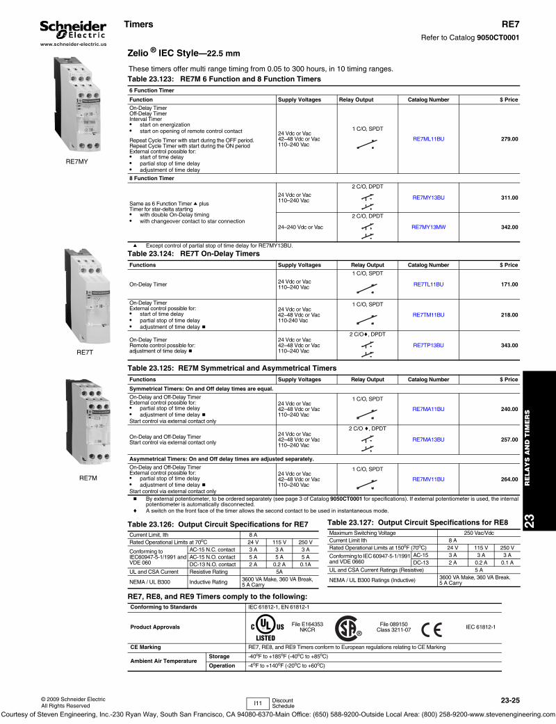
www.schneider-electric.us
23R
ELA
YS
AN
D T
IME
RS
© 2009 Schneider ElectricAll Rights Reserved
23-25
Timers RE7Refer to Catalog 9050CT0001
Zelio ® IEC Style—22.5 mm
a Except control of partial stop of time delay for RE7MY13BU.
RE7MY
These timers offer multi range timing from 0.05 to 300 hours, in 10 timing ranges.Table 23.123: RE7M 6 Function and 8 Function Timers6 Function Timer
Function Supply Voltages Relay Output Catalog Number $ Price
On-Delay Timer Off-Delay TimerInterval Timer• start on energization• start on opening of remote control contact
Repeat Cycle Timer with start during the OFF period.Repeat Cycle Timer with start during the ON periodExternal control possible for:• start of time delay• partial stop of time delay• adjustment of time delay
24 Vdc or Vac42–48 Vdc or Vac110–240 Vac
1 C/O, SPDT
RE7ML11BU 279.00
8 Function Timer
Same as 6 Function Timer a plusTimer for star-delta starting• with double On-Delay timing• with changeover contact to star connection
24 Vdc or Vac110–240 Vac
2 C/O, DPDT
RE7MY13BU 311.00
24–240 Vdc or Vac
2 C/O, DPDT
RE7MY13MW 342.00
RE7T
RE7M
Table 23.124: RE7T On-Delay TimersFunctions Supply Voltages Relay Output Catalog Number $ Price
On-Delay Timer 24 Vdc or Vac110–240 Vac
1 C/O, SPDT
RE7TL11BU 171.00
On-Delay TimerExternal control possible for:• start of time delay• partial stop of time delay• adjustment of time delay b
24 Vdc or Vac42–48 Vdc or Vac110-240 Vac
1 C/O, SPDT
RE7TM11BU 218.00
On-Delay TimerRemote control possible for:adjustment of time delay b
24 Vdc or Vac42–48 Vdc or Vac110–240 Vac
2 C/Oc, DPDT
RE7TP13BU 343.00
Table 23.125: RE7M Symmetrical and Asymmetrical TimersFunctions Supply Voltages Relay Output Catalog Number $ Price
Symmetrical Timers: On and Off delay times are equal.
On-Delay and Off-Delay TimerExternal control possible for:• partial stop of time delay• adjustment of time delay bStart control via external contact only
24 Vdc or Vac42–48 Vdc or Vac110–240 Vac
1 C/O, SPDT
RE7MA11BU 240.00
On-Delay and Off-Delay TimerStart control via external contact only
24 Vdc or Vac42–48 Vdc or Vac110–240 Vac
2 C/O c, DPDT
RE7MA13BU 257.00
Asymmetrical Timers: On and Off delay times are adjusted separately.
On-Delay and Off-Delay TimerExternal control possible for:• partial stop of time delay• adjustment of time delay bStart control via external contact only
24 Vdc or Vac42–48 Vdc or Vac110–240 Vac
1 C/O, SPDT
RE7MV11BU 264.00
b By external potentiometer, to be ordered separately (see page 3 of Catalog 9050CT0001 for specifications). If external potentiometer is used, the internal potentiometer is automatically disconnected.
c A switch on the front face of the timer allows the second contact to be used in instantaneous mode.
Table 23.126: Output Circuit Specifications for RE7Current Limit, Ith 8 ARated Operational Limits at 70oC 24 V 115 V 250 V
Conforming toIEC60947-5-1/1991 andVDE 060
AC-15 N.C. contact 3 A 3 A 3 AAC-15 N.O. contact 5 A 5 A 5 ADC-13 N.O. contact 2 A 0.2 A 0.1A
UL and CSA Current Resistive Rating 5A
NEMA / UL B300 Inductive Rating 3600 VA Make, 360 VA Break, 5 A Carry
Table 23.127: Output Circuit Specifications for RE8Maximum Switching Voltage 250 Vac/VdcCurrent Limit Ith 8 ARated Operational Limits at 150oF (70oC) 24 V 115 V 250 V
Conforming to IEC 60947-5-1/1991 and VDE 0660
AC-15 3 A 3 A 3 ADC-13 2 A 0.2 A 0.1 A
UL and CSA Current Ratings (Resistive) 5 A
NEMA / UL B300 Ratings (Inductive) 3600 VA Make, 360 VA Break. 5 A Carry
RE7, RE8, and RE9 Timers comply to the following:Conforming to Standards IEC 61812-1, EN 61812-1
Product Approvals File E164353NKCR
File 089150Class 3211-07 IEC 61812-1
CE Marking RE7, RE8, and RE9 Timers conform to European regulations relating to CE Marking
Ambient Air TemperatureStorage -40oF to +185oF (-40oC to +85oC)
Operation -4oF to +140oF (-20oC to +60oC)
I11 Discount Schedule
Courtesy of Steven Engineering, Inc.-230 Ryan Way, South San Francisco, CA 94080-6370-Main Office: (650) 588-9200-Outside Local Area: (800) 258-9200-www.stevenengineering.com
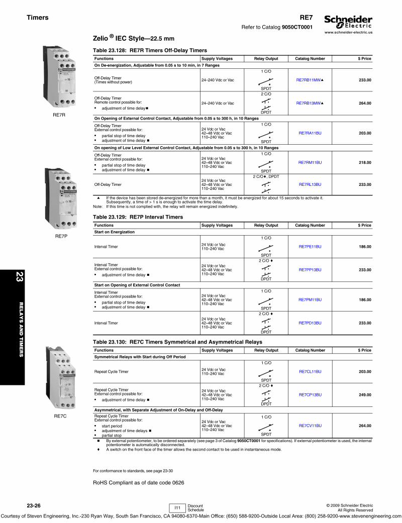
www.schneider-electric.us
23R
EL
AY
S A
ND
TIM
ER
S
23-26 © 2009 Schneider ElectricAll Rights Reserved
Timers RE7Refer to Catalog 9050CT0001
Zelio ® IEC Style—22.5 mm
a If the device has been stored de-energized for more than a month, it must be energized for about 15 seconds to activate it. Subsequently, a time of > 1 s is enough to activate the time delay.
Note: If this time is not complied with, the relay will remain energized indefinitely.
b By external potentiometer, to be ordered separately (see page 3 of Catalog 9050CT0001 for specifications). If external potentiometer is used, the internal potentiometer is automatically disconnected.
c A switch on the front face of the timer allows the second contact to be used in instantaneous mode.
For conformance to standards, see page 23-30
RoHS Compliant as of date code 0626
Table 23.128: RE7R Timers Off-Delay TimersFunctions Supply Voltages Relay Output Catalog Number $ Price
On De-energization, Adjustable from 0.05 s to 10 min, in 7 Ranges
Off-Delay Timer(Times without power) 24–240 Vdc or Vac
1 C/O
SPDT
RE7RB11MWa 233.00
Off-Delay TimerRemote control possible for:
• adjustment of time delayb24–240 Vdc or Vac
2 C/O
DPDT
RE7RB13MWa 264.00
On Opening of External Control Contact, Adjustable from 0.05 s to 300 h, in 10 Ranges
Off-Delay TimerExternal control possible for:
• partial stop of time delay• adjustment of time delay b
24 Vdc or Vac42–48 Vdc or Vac110–240 Vac
1 C/O
SPDT
RE7RA11BU 203.00
On opening of Low Level External Control Contact, Adjustable from 0.05 s to 300 h, in 10 Ranges
Off-Delay TimerExternal control possible for:
• partial stop of time delay• adjustment of time delay b
24 Vdc or Vac42–48 Vdc or Vac110–240 Vac
1 C/O
SPDT
RE7RM11BU 218.00
Off-Delay Timer24 Vdc or Vac42–48 Vdc or Vac110–240 Vac
2 C/Oc, DPDT
RE7RL13BU 233.00
Table 23.129: RE7P Interval TimersFunctions Supply Voltages Relay Output Catalog Number $ Price
Start on Energization
Interval Timer 24 Vdc or Vac110–240 Vac
1 C/O
SPDT
RE7PE11BU 186.00
Interval TimerExternal control possible for:
• adjustment of time delay b
24 Vdc or Vac42–48 Vdc or Vac110–240 Vac
2 C/O c
DPDT
RE7PP13BU 233.00
Start on Opening of External Control Contact
Interval TimerExternal control possible for:
• partial stop of time delay• adjustment of time delay b
24 Vdc or Vac42–48 Vdc or Vac110–240 Vac
1 C/O
SPDT
RE7PM11BU 186.00
Interval Timer24 Vdc or Vac42–48 Vdc or Vac110–240 Vac
2 C/O c
DPDT
RE7PD13BU 233.00
Table 23.130: RE7C Timers Symmetrical and Asymmetrical RelaysFunctions Supply Voltages Relay Output Catalog Number $ Price
Symmetrical Relays with Start during Off Period
Repeat Cycle Timer 24 Vdc or Vac110–240 Vac
1 C/O
SPDT
RE7CL11BU 203.00
Repeat Cycle TimerExternal control possible for:
• adjustment of time delay b
24 Vdc or Vac42–48 Vdc or Vac110–240 Vac
2 C/O c
DPDT
RE7CP13BU 249.00
Asymmetrical, with Separate Adjustment of On-Delay and Off-Delay
Repeat Cycle TimerExternal control possible for:
• start period• adjustment of time delays b• partial stop
24 Vdc or Vac42–48 Vdc or Vac110–240 Vac
1 C/O
SPDT
RE7CV11BU 264.00
RE7R
RE7P
RE7C
I11 Discount Schedule
Courtesy of Steven Engineering, Inc.-230 Ryan Way, South San Francisco, CA 94080-6370-Main Office: (650) 588-9200-Outside Local Area: (800) 258-9200-www.stevenengineering.com

www.schneider-electric.us
23R
ELA
YS
AN
D T
IME
RS
© 2009 Schneider ElectricAll Rights Reserved
23-27
Timers RE8/RE9Refer to Catalog 9050CT0001
Zelio ® IEC Style—22.5 mm
d Also available in pack of one; delete TQ from the end of the catalog number. Example: RE8TA11BU.
a For easier adjustment, it is preferable to set the time delay between the maximum value in the range and one tenth of this value. Example: RE8TA11BUTQ timing range 0.1–10 s, recommended use 1–10 s.
b Orders must specify standard pack quantity or multiples of that quantity.
For technical information, refer to . . . . . . . . . . . . . . . . . . . . . . . . page 23-30.
c For easier adjustment, it is preferable to set the time delay between the maximum value in the range and one tenth of this value. Example: RE9TA11MW timing range 0.1-10 s, recommended use 1-10 s.
RoHS Compliant as of date code 0626
For technical information, refer to catalog 9050CT0001.
Table 23.131: On-Delay (timing starts on energization), TDERelay Output Supply Voltages Timing Range a Catalog Number Standard Pack Quantity b $ Price
1 C/O
SPDT
24 Vdc or Vac110–240 Vac
0.1–3 s RE8TA61BUTQ 10 93.000.1–10 s RE8TA11BUTQ d 10 93.000.3–30 s RE8TA31BUTQ d 10 93.003–300 s RE8TA21BUTQ d 10 93.00
20 s–30 min RE8TA41BUTQ 10 93.00
Table 23.132: Off-Delay (timing starts on de-energization), TDDControl Contact
1 C/O
SPDT
24 Vdc or Vac0.1–10 s RE8RA11BTQ d 10 117.000.3–30 s RE8RA31BTQ 10 117.003–300 s RE8RA21BTQ d 10 117.00
110–240 Vac
0.1–10 s RE8RA11FUTQ d 10 117.000.3–30 s RE8RA31FUTQ 10 117.003–300 s RE8RA21FUTQ d 10 117.00
20 s–30 min RE8RA41FUTQ 10 117.00
Self-Powered (Times without power)
1 C/O
SPDT
24 Vdc or Vac110–240 Vac
0.05–0.5 s RE8RB51BUTQ 10 186.000.1–10 s RE8RB11BUTQ 10 186.00
0.3–30 s RE8RB31BUTQ 10 186.00
Table 23.133: Repeat Cycle TimerRelay Output Supply Voltages Timing Range a Catalog Number Standard Pack Quantity b $ Price
1 C/O
SPDT
24 Vdc or Vac110–240 Vac 0.1–10 s RE8CL11BUTQ 10 125.00
Table 23.134: Interval TimerOn Energization
1 C/O
SPDT
24 Vdc or Vac110–240 Vac
0.1–10 s RE8PE11BUTQ 10 108.000.3–30 s RE8PE31BUTQ 10 108.00
3–300 s RE8PE21BUTQ 10 108.00
By Control Contact
1 C/O
SPDT
24 Vdc or Vac0.1–10 s RE8PD11BTQ 10 125.000.3–30 s RE8PD31BTQ 10 125.003–300 s RE8PD21BTQ 10 125.00
110–240 Vac0.1–10 s RE8PD11FUTQ 10 125.000.3–30 s RE8PD31FUTQ 10 125.003–300 s RE8PD21FUTQ 10 125.00
On De-Energization
1 C/O
SPDT
24 Vdc or Vac110–240 Vac 0.05–1 s RE8PT01BUTQ 10 132.00
Table 23.135: On-Delay Timer (Solid State Output)Power Supply Circuit Function Timing Range c Catalog Number $ Price
24–240 Vac or Vdc On-Delay
0.1–10 s RE9TA11MW 108.000.3–30 s RE9TA31MW 108.003–300 s RE9TA21MW 108.00
40 s–60 min RE9TA51MW 108.00
Table 23.136: Off-Delay Timer (Solid State Output)
24–240 Vac Off-Delay
0.1–10 s RE9RA11MW7 156.000.3–30 s RE9RA31MW7 156.003–300 s RE9RA21MW7 156.00
40 s–60 min RE9RA51MW7 156.00
RE8TA
RE8PE
RE9TA
I11 Discount Schedule
Courtesy of Steven Engineering, Inc.-230 Ryan Way, South San Francisco, CA 94080-6370-Main Office: (650) 588-9200-Outside Local Area: (800) 258-9200-www.stevenengineering.com

www.schneider-electric.us
23R
EL
AY
S A
ND
TIM
ER
S
23-28 © 2009 Schneider ElectricAll Rights Reserved
Square D® General Purpose Plug-In9050JCK timing relays are designed to provide low-cost timing in a plug-in housing. The Types JCK11 thru 59 provide ±1% repeat accuracy. The Types JCK60 and 70 offer ±0.1% repeat accuracy. These timers are directly interchangeable with many other 8 and 11 pin tube base timers.
• Up to ±0.1% repeat accuracy• Timing from 0.05 seconds to 999 hours• Available in 5 timing modes• DPDT contacts (2 N.O. and 2 N.C.)• 10 A contact rating• Transient protected• Hold down spring available• Variable or fixed time delay• Horsepower rated• RoHS compliant
c (XXXX) denotes the timing period in seconds. Example: Class 9050 Type JCK1F60 is an On Delay timer fixed at 60 seconds.
d Fixed repeat cycle timers can be supplied with the same or different On-Time and Off-Time.
e Initiating contact can be up to 50 feet from the timer.f Voltage code must be specified to order this product. Refer to standard voltage codes
listed below and insert as shown in How To Order.
Class 8501 Sockets For sockets, see page 23-13For DIN rail, see page 24-16
For all 9050JCK timers:
B300, R300, AC15 and DC13
Type JCK60This On Delay timer uses a 5 position rotary switch to select the timing range. The three pushbutton thumbwheels are used to select the time value.
Type JCK70Two 5 position rotary switches are used to select the timing mode and timing range. The three pushbutton thumbwheels are used to select the time value.
g The repeat cycle mode utilizes the same on-time and off-time.
9050JCK46V209050JCK32V36 with 8501NH7
Table 23.137: Variable Time DelayKnob AdjustableTiming Range
OnDelay $ Price Off
Delayb $ Price Off Delay Power Trigger $ Price Interval $ Price One Shotb $ Price One Shot
Power Trigger $ Price RepeatCyclea $ Price
0.1–10 seconds JCK11f 78.00 JCK21f 98.00 JCK21PTf 98.00 JCK31f 78.00 JCK41f 98.00 JCK41PTf 98.00 JCK51f 140.000.3–30 seconds JCK12f 78.00 JCK22f 98.00 JCK22PTf 98.00 JCK32f 78.00 JCK42f 98.00 JCK42PTf 98.00 JCK52f 140.000.6–60 seconds JCK13f 78.00 JCK23f 98.00 JCK23PTf 98.00 JCK33f 78.00 JCK43f 98.00 JCK43PTf 98.00 JCK53f 140.001.2–120 seconds JCK14f 78.00 JCK24f 98.00 JCK24PTf 98.00 JCK34f 78.00 JCK44f 98.00 JCK44PTf 98.00 JCK54f 140.001.8–180 seconds JCK15f 78.00 JCK25f 98.00 JCK25PTf 98.00 JCK35f 78.00 JCK45f 98.00 JCK45PTf 98.00 JCK55f 140.000.1–10 minutes JCK16f 87.00 JCK26f 107.00 JCK26PTf 107.00 JCK36f 87.00 JCK46f 107.00 JCK46PTf 107.00 JCK56f 147.000.3–30 minutes JCK17f 87.00 JCK27f 107.00 JCK27PTf 107.00 JCK37f 87.00 JCK47f 107.00 JCK47PTf 107.00 JCK57f 98.000.6–60 minutes JCK18f 87.00 JCK28f 107.00 JCK28PTf 107.00 JCK38f 87.00 JCK48f 107.00 JCK48PTf 107.00 JCK58f 98.001.2–120 minutes JCK19f 87.00 JCK29f 107.00 JCK29PTf 107.00 JCK39f 87.00 JCK49f 107.00 JCK49PTf 107.00 JCK59f 98.00a Two dials are provided for independently adjustable repeat cycle timing ranges.b Initiating contact can be up to 50 feet from the timer.
Table 23.138: Fixed Time DelayTiming Mode Type Timing Range (seconds) $ Price
On Delay JCK1F(XXXX)cf0.1 to 180 78.00181 to 3600 87.00
Off Delay e JCK2F(XXXX)cf0.1 to 180 98.00181 to 3600 107.00
Off Delay with Power Trigger JCK2F(XXXX)PTcf
0.1 to 180 98.00181 to 3600 107.00
Interval JCK3F(XXXX)cf0.1 to 180 78.00181 to 3600 87.00
One Shote JCK4F(XXXX)cf0.1 to 180 98.00181 to 3600 107.00
One Shot with Power Trigger JCK4F(XXXX)PTcf
0.1 to 180 98.00181 to 3600 107.00
Repeat Cycle JCK5F(XXXX)cdf0.1 to 180 140.00181 to 3600 147.00
With appropriate 8501NR Socket:
FileCCN
E78351NLDX
FileClass
2147683211 07
Without Socket
FileCCN
E78351NLDX2
IEC 60947-1
RoHSCompliant
as of date code
9050JCK1-5 = 06279050JCK6070=0648
Table 23.139: Voltage CodesVoltage Code
12 Vac/Vdc V3624 Vac/Vdc V1448 Vac/Vdc V17120 Vac/110 Vdc V20240–50/60 V24
Table 23.140: Contact Ratings
ACVolts
AC Amperes
hp DCVolts
DC Amperes
Inductive 35% P.F.
Res
. 75%
P.F
.M
ake
Bre
ak a
ndC
ontin
uous
Inductive
Res
. Mak
e B
reak
and
Con
tinuo
us
Mak
e
Bre
ak
Con
tinuo
us
Mak
e
Bre
ak
120 30 3 10 10 1/328 3 3 10
240 15 1.5 10 10 1/2
Table 23.141: Selection and PricingTimingModes
TimingRanges Type $ Price
On Delay
.01s 0.1sS0.1mM0.1hH
0.05–9.99 seconds00.1–99.9 seconds001–999 seconds00.1–99.9 minutes001–999 minutes00.1–99.9 hours001–999 hours
JCK60f 152.00
Table 23.142: Selection and PricingTimingModes
TimingRange Type $ Price
On DelayOff DelayIntervalOne ShotRepeat Cycleg
Same asJCK60 JCK70f 173.00
Table 23.143: Class 8501 Hold Down SpringFor use on Class 9050 Type JCK Timers Class Type $ Price ea.
Hold down spring holds timer in socket during heavy vibration. (See 9050JCK with 8501NH7 photo at the top of this page.) 8501 NH7 8.30
Table 23.144: How to OrderTo Order Specify: Catalog Number
• Class Number• Type Number• Voltage Code
Class Type Voltage Code
9050 JCK11 V20
CP2 Discount Schedule
Timers Type JCKClass 9050 / Refer to Catalog 9050CT9601
Courtesy of Steven Engineering, Inc.-230 Ryan Way, South San Francisco, CA 94080-6370-Main Office: (650) 588-9200-Outside Local Area: (800) 258-9200-www.stevenengineering.com

www.schneider-electric.us
23R
ELA
YS
AN
D T
IME
RS
© 2009 Schneider ElectricAll Rights Reserved
23-29
Timers Types A and HClass 9050 / Refer to Catalog 9050CT9901
Square D® Pneumatic• One minute timing ± 10% repeat accuracy• SPDT or DPDT instantaneous contacts (Type A only)• On and Off Delay, convertible • SPDT or DPDT timed contacts• Small size• Low cost
a Voltage code must be specified to order this product. Refer to standard voltage codes listed below and insert as shown in How To Order.
b Instantaneous contact kits contain a snap switch, mounting bracket and screws for field installation.
Timing Modes: On Delay or Off Delay, convertible. On Delay types can be wired for interval-maintained start or repeat cycle (sequencing using two devices).Timed and Instantaneous Output Contacts: SPDT or DPDT snap switch. Contacts of each pole must be used on same polarity.Repeat Accuracy: Under constant temperature (Per NEMA Standard ICS 5-1993). ±10% to 1 minute max.Timing Range: Type A: 0.1 second to 1 minute. Type H: 0.15 second to 1 minute.Reset Time: Type A: On Delay 29 ms, Off Delay 27 ms average. Type H: On Delay 50 ms, Off Delay 70 ms average.Operating Temperature Range: 20oC to 40oC (68oF to 104oF)Operating Voltages/Voltage Range: Type A—6 through 600 volts AC, +10%, -15% of nominalType H—6 through 250 volts DC, +10%, -20% of nominal
c 6 to 24 Vac coils have VA ratings 120% of the values shown
Table 23.145: Selection and Pricing
Mode ofOperation
Number of Contacts AC Operated DC Operated
Time Delay InstantaneousOpen Type $ Price Open Type $ Price
N.O. N.C. N.O. N.C.
On DelayConvertible
1 1012
012
AO10EaAO11EaAO12Ea
504.00629.00675.00
HO10Ea——
777.00——
2 2012
012
AO20EaAO21EaAO22Ea
549.00675.00720.00
HO20Ea——
569.00——
Off DelayConvertible
1 1012
012
AO10DaAO11DaAO12Da
504.00629.00675.00
HO10Da——
518.00——
2 2012
012
AO20DaAO21DaAO22Da
549.00675.00720.00
HO20Da——
569.00——
On and Off DelayDouble Headed
1 per Head2 per Head
1 per Head2 per Head
00
00
AO110DEaAO220DEa
818.00909.00
——
——
Type AO10E
Type HO10E
Types A and H
FileCCN
E78403NKCR
FileClass
0609053211 03
Table 23.146: AccessoriesClass Type For Timing Relay Description $ Price
9991 UE6 Type A (single headed)Type H Separate NEMA 1 Enclosure 99.00
9999 R33b Type A SPDT Instantaneous Contact Kits (1 N.O., 1 N.C.) 126.009999 R34b Type A DPDT Instantaneous Contact Kits (2 N.O., 2 N.C.) 171.00
Table 23.147: Voltage CodesAC Voltages Code DC Voltages Code
24–6024–50120–60/110–50208–60240–60/220–50277–60480–60/440–50600–60/550–50
V01V12V02V08V03V04V06V07
6122448
115230/250
V50V51V53V56V61V66
Table 23.148: DC Replacement Coils
Coil Voltage Coil Part Number
Coil Burden Watts $ Price
6 Vdc 4491S1W21
14 228.00
12 Vdc 4491S1W2424 Vdc 4491S1W2748 Vdc 4491S1W30
115/125 Vdc 4491S1W34230/250 Vdc 4491S1W37
Table 23.149: AC Replacement Coils
Coil VoltageCoil Part Number Coil (Volt-Amperes) c
$ Price60 Hz 50 Hz Inrush
60 HzInrush 50 Hz Sealed
24 Vac 2959S49W25A 2959S49W25B
74 68 17 144.00
110/115 Vac 2959S49W31B 2959S49W32A120 Vac 2959S49W32A 2959S49W32B208 Vac 2959S49W34A 2959S49W34B220 Vac 2959S49W34B 2959S49W35A240 Vac 2959S49W35A 2959S49W35B277 Vac 2959S49W35B —440 Vac 2959S49W37B 2959S49W38A480 Vac 2959S49W38A 2959S49W38B550 Vac 2959S49W38B 2959S49W39A
Table 23.150: Contact Ratings
Contacts Volts
AC Ratings
Volts
DC Ratings
Inductive35% Power Factor
Resistive75% Power Factor
Inductiveand Resistive
Make Break ContinuousAmperes
Make, Break andContinuous Amperes
Make and Break Amperes ContinuousAmperesAmperes VA Amperes VA Single Throw Double Throw
SPDTTimed or Instantaneous
120240480600
4020108
———
151065
————
15151515
15151515
115230600—
2.00.50.1—
0.50.20.02—
151515—
DPDTTimed or Instantaneous
120240480600
30157.56
3600360036003600
31.50.750.6
360360360360
10101010
10101010
115230600—
1.00.30.1—
0.20.1——
101010—
CP1 Discount Schedule
Courtesy of Steven Engineering, Inc.-230 Ryan Way, South San Francisco, CA 94080-6370-Main Office: (650) 588-9200-Outside Local Area: (800) 258-9200-www.stevenengineering.com
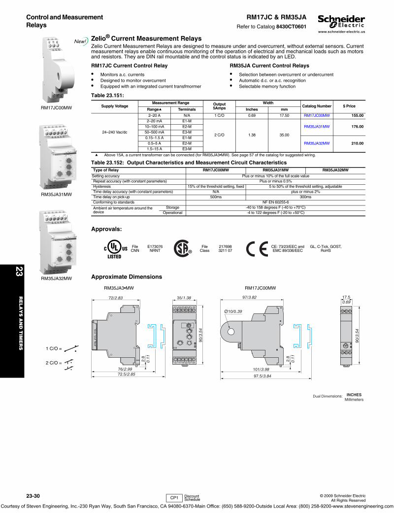
www.schneider-electric.us
23R
EL
AY
S A
ND
TIM
ER
S
23-30 © 2009 Schneider ElectricAll Rights Reserved
Control and Measurement Relays
RM17JC & RM35JARefer to Catalog 8430CT0601
Zelio® Current Measurement RelaysZelio Current Measurement Relays are designed to measure under and overcurrent, without external sensors. Current measurement relays enable continuous monitoring of the operation of electrical and mechanical loads such as motors and resistors. They are DIN rail mountable and the control status is indicated by an LED.
a Above 15A, a current transformer can be connected (for RM35JA3•MW). See page 57 of the catalog for suggested wiring.
Approvals:
Approximate Dimensions
Table 23.151:
Supply VoltageMeasurement Range Output
5AmpsWidth
Catalog Number $ PriceRangea Terminals Inches mm
24–240 Vac/dc
2–20 A N/A 1 C/O 0.69 17.50 RM17JC00MW 155.002–20 mA E1-M
2 C/O 1.38 35.00
RM35JA31MW 176.0010–100 mA E2-M50–500 mA E3-M0.15–1.5 A E1-M
RM35JA32MW 210.000.5–5 A E2-M1.5–15 A E3-M
Table 23.152: Output Characteristics and Measurement Circuit CharacteristicsType of Relay RM17JC00MW RM35JA31MW RM35JA32MW
Setting accuracy Plus or minus 10% of the full scale valueRepeat accuracy (with constant parameters) Plus or minus 0.5%Hysteresis 15% of the threshold setting, fixed 5 to 50% of the threshold setting, adjustableTime delay accuracy (with constant parameters) N/A plus or minus 2%Time delay on pick-up 500ms 300msConforming to standards NF EN 60255-6
Ambient air temperature around the device
Storage -40 to 158 degrees F (-40 to +70°C)Operational -4 to 122 degrees F (-20 to +50°C)
FileCNN
E173076NRNT
FileClass
2176983211 07
CE: 73/23/EEC and EMC 89/336/EEC
GL, C-Tick, GOST, RoHS
RM17JC00MW
New!
RM35JA31MW
1 C/O =
2 C/O =
RM35JA32MW
RM17JC Current Control Relay
• Monitors a.c. currents• Designed to monitor overcurrent• Equipped with an integrated current transfmormer
RM35JA Current Control Relays
• Selection between overcurrent or undercurrent• Automatic d.c. or a.c. recognition• Selectable memory function
72/2.83
2.8
0.11
76/2.9972.5/2.85
90/3
.54
35/1.38
A1
12 22 21 241411
A2 E3 E2 E1 M
97/3.82 17.50.69
90/3
.54
2.8
0.11
101/3.98
97.5/3.84
10/0.39
RM35JA3•MW RM17JC00MW
Dual Dimensions: INCHESMillimeters
CP1 Discount Schedule
Courtesy of Steven Engineering, Inc.-230 Ryan Way, South San Francisco, CA 94080-6370-Main Office: (650) 588-9200-Outside Local Area: (800) 258-9200-www.stevenengineering.com
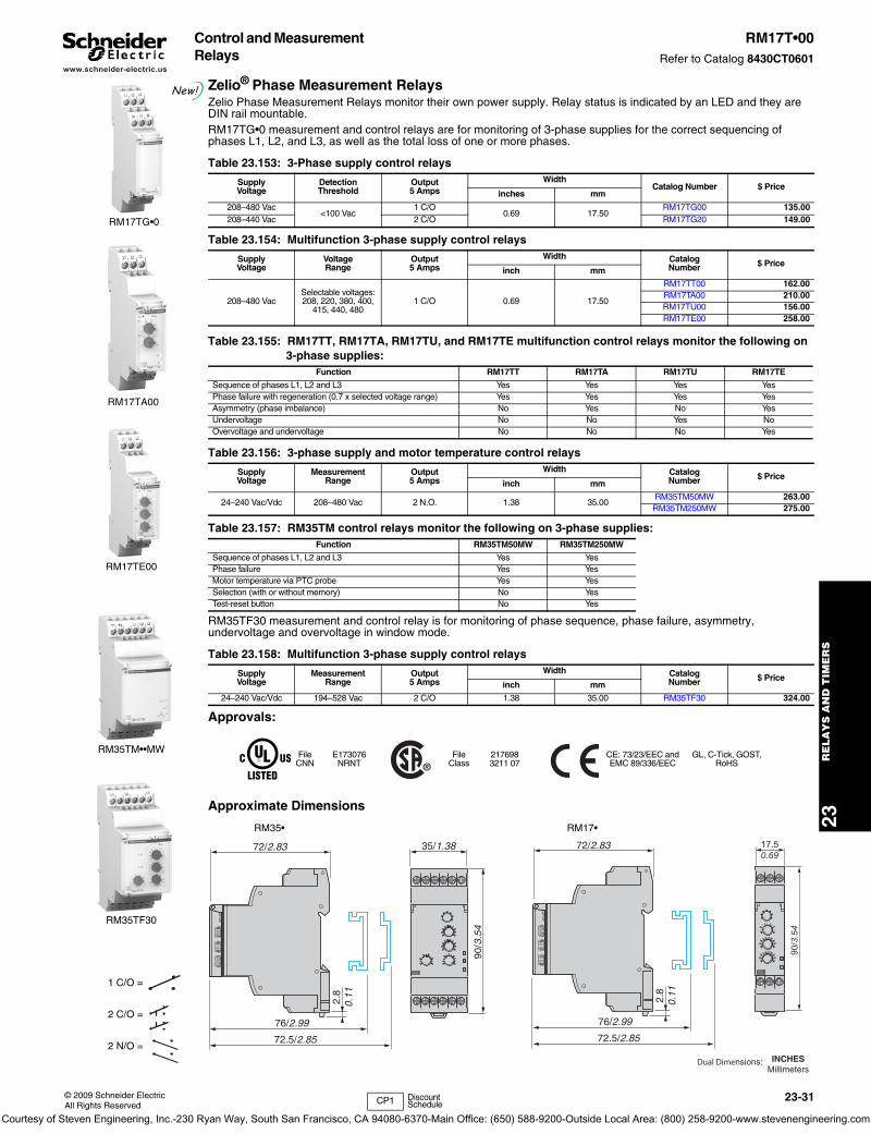
www.schneider-electric.us
23R
ELA
YS
AN
D T
IME
RS
© 2009 Schneider ElectricAll Rights Reserved
23-31
Control and Measurement Relays
RM17T•00Refer to Catalog 8430CT0601
Zelio® Phase Measurement RelaysZelio Phase Measurement Relays monitor their own power supply. Relay status is indicated by an LED and they are DIN rail mountable.RM17TG•0 measurement and control relays are for monitoring of 3-phase supplies for the correct sequencing of phases L1, L2, and L3, as well as the total loss of one or more phases.
RM35TF30 measurement and control relay is for monitoring of phase sequence, phase failure, asymmetry, undervoltage and overvoltage in window mode.
Approvals:
Approximate Dimensions
Table 23.153: 3-Phase supply control relays
SupplyVoltage
DetectionThreshold
Output5 Amps
WidthCatalog Number $ Price
inches mm
208–480 Vac<100 Vac
1 C/O0.69 17.50
RM17TG00 135.00208–440 Vac 2 C/O RM17TG20 149.00
Table 23.154: Multifunction 3-phase supply control relays
SupplyVoltage
VoltageRange
Output5 Amps
Width CatalogNumber $ Price
inch mm
208–480 VacSelectable voltages:208, 220, 380, 400,
415, 440, 4801 C/O 0.69 17.50
RM17TT00 162.00RM17TA00 210.00RM17TU00 156.00RM17TE00 258.00
Table 23.155: RM17TT, RM17TA, RM17TU, and RM17TE multifunction control relays monitor the following on 3-phase supplies:
Function RM17TT RM17TA RM17TU RM17TE
Sequence of phases L1, L2 and L3 Yes Yes Yes YesPhase failure with regeneration (0.7 x selected voltage range) Yes Yes Yes YesAsymmetry (phase imbalance) No Yes No YesUndervoltage No No Yes NoOvervoltage and undervoltage No No No Yes
Table 23.156: 3-phase supply and motor temperature control relays
SupplyVoltage
MeasurementRange
Output5 Amps
Width CatalogNumber $ Price
inch mm
24–240 Vac/Vdc 208–480 Vac 2 N.O. 1.38 35.00RM35TM50MW 263.00RM35TM250MW 275.00
Table 23.157: RM35TM control relays monitor the following on 3-phase supplies:Function RM35TM50MW RM35TM250MW
Sequence of phases L1, L2 and L3 Yes YesPhase failure Yes YesMotor temperature via PTC probe Yes YesSelection (with or without memory) No YesTest-reset button No Yes
Table 23.158: Multifunction 3-phase supply control relays
SupplyVoltage
MeasurementRange
Output5 Amps
Width CatalogNumber $ Price
inch mm
24–240 Vac/Vdc 194–528 Vac 2 C/O 1.38 35.00 RM35TF30 324.00
FileCNN
E173076NRNT
FileClass
2176983211 07
CE: 73/23/EEC and EMC 89/336/EEC
GL, C-Tick, GOST, RoHS
RM17TG•0
New!
RM17TA00
1 C/O =
2 C/O =
2 N/O =
RM17TE00
RM35TM••MW
RM35TF30
RM35• RM17•
2.8
0.11
76/2.99
72.5/2.85
72/2.83
90/3
.54
35/1.38
2.8
0.11
76/2.99
72.5/2.85
72/2.83 17.50.69
90/3
.54
Dual Dimensions: INCHESMillimeters
CP1 Discount Schedule
Courtesy of Steven Engineering, Inc.-230 Ryan Way, South San Francisco, CA 94080-6370-Main Office: (650) 588-9200-Outside Local Area: (800) 258-9200-www.stevenengineering.com
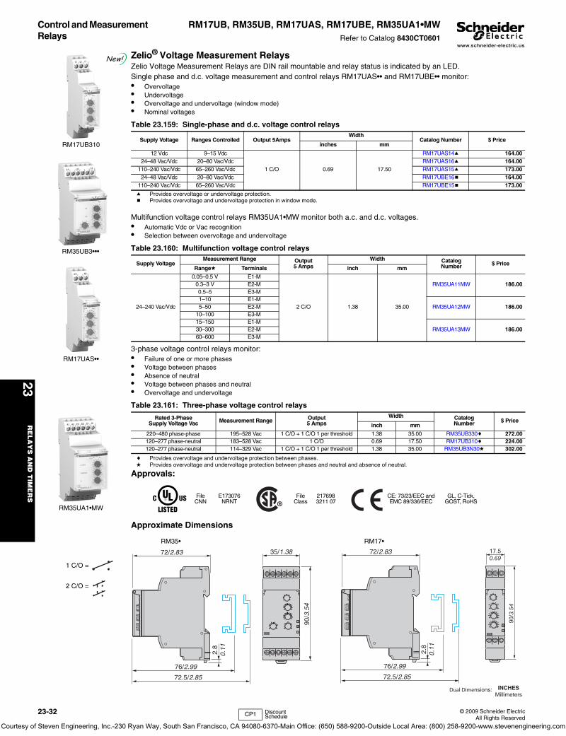
www.schneider-electric.us
23R
EL
AY
S A
ND
TIM
ER
S
23-32 © 2009 Schneider ElectricAll Rights Reserved
Control and Measurement Relays
RM17UB, RM35UB, RM17UAS, RM17UBE, RM35UA1•MWRefer to Catalog 8430CT0601
Zelio® Voltage Measurement RelaysZelio Voltage Measurement Relays are DIN rail mountable and relay status is indicated by an LED.Single phase and d.c. voltage measurement and control relays RM17UAS•• and RM17UBE•• monitor:• Overvoltage• Undervoltage• Overvoltage and undervoltage (window mode)• Nominal voltages
a Provides overvoltage or undervoltage protection.b Provides overvoltage and undervoltage protection in window mode.
Multifunction voltage control relays RM35UA1•MW monitor both a.c. and d.c. voltages.• Automatic Vdc or Vac recognition• Selection between overvoltage and undervoltage
3-phase voltage control relays monitor:• Failure of one or more phases• Voltage between phases• Absence of neutral• Voltage between phases and neutral• Overvoltage and undervoltage
c Provides overvoltage and undervoltage protection between phases.d Provides overvoltage and undervoltage protection between phases and neutral and absence of neutral.
Approvals:
Approximate Dimensions
Table 23.159: Single-phase and d.c. voltage control relays
Supply Voltage Ranges Controlled Output 5AmpsWidth
Catalog Number $ Priceinches mm
12 Vdc 9–15 Vdc
1 C/O 0.69 17.50
RM17UAS14a 164.0024–48 Vac/Vdc 20–80 Vac/Vdc RM17UAS16a 164.00
110–240 Vac/Vdc 65–260 Vac/Vdc RM17UAS15a 173.0024–48 Vac/Vdc 20–80 Vac/Vdc RM17UBE16b 164.00
110–240 Vac/Vdc 65–260 Vac/Vdc RM17UBE15b 173.00
Table 23.160: Multifunction voltage control relays
Supply VoltageMeasurement Range Output
5 AmpsWidth Catalog
Number $ PriceRanged Terminals inch mm
24–240 Vac/Vdc
0.05–0.5 V E1-M
2 C/O 1.38 35.00
RM35UA11MW 186.000.3–3 V E2-M0.5–5 E3-M1–10 E1-M
RM35UA12MW 186.005–50 E2-M10–100 E3-M15–150 E1-M
RM35UA13MW 186.0030–300 E2-M60–600 E3-M
Table 23.161: Three-phase voltage control relays
Rated 3-PhaseSupply Voltage Vac Measurement Range Output
5 AmpsWidth Catalog
Number $ Priceinch mm
220–480 phase-phase 195–528 Vac 1 C/O + 1 C/O 1 per threshold 1.38 35.00 RM35UB330c 272.00120–277 phase-neutral 183–528 Vac 1 C/O 0.69 17.50 RM17UB310c 224.00120–277 phase-neutral 114–329 Vac 1 C/O + 1 C/O 1 per threshold 1.38 35.00 RM35UB3N30d 302.00
FileCNN
E173076NRNT
FileClass
2176983211 07
CE: 73/23/EEC and EMC 89/336/EEC
GL, C-Tick, GOST, RoHS
RM17UB310
New!
RM35UB3•••
1 C/O =
2 C/O =
RM17UAS••
RM35UA1•MW
2.8
0.11
76/2.99
72.5/2.85
72/2.83
90/3
.54
35/1.38
2.8
0.11
76/2.99
72.5/2.85
72/2.83 17.50.69
90/3
.54
Dual Dimensions: INCHESMillimeters
RM35• RM17•
CP1 Discount Schedule
Courtesy of Steven Engineering, Inc.-230 Ryan Way, South San Francisco, CA 94080-6370-Main Office: (650) 588-9200-Outside Local Area: (800) 258-9200-www.stevenengineering.com
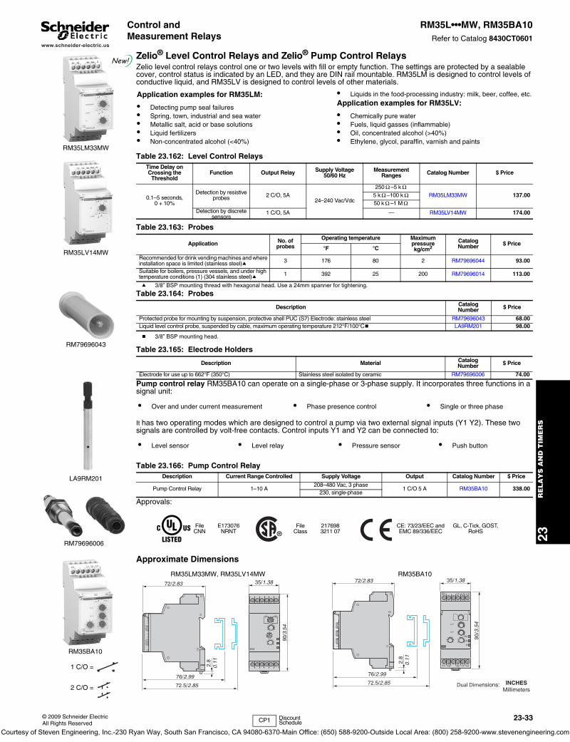
www.schneider-electric.us
23R
ELA
YS
AN
D T
IME
RS
© 2009 Schneider ElectricAll Rights Reserved
23-33
Control and Measurement Relays
RM35L•••MW, RM35BA10Refer to Catalog 8430CT0601
Zelio® Level Control Relays and Zelio® Pump Control RelaysZelio level control relays control one or two levels with fill or empty function. The settings are protected by a sealable cover, control status is indicated by an LED, and they are DIN rail mountable. RM35LM is designed to control levels of conductive liquid, and RM35LV is designed to control levels of other materials.
a 3/8” BSP mounting thread with hexagonal head. Use a 24mm spanner for tightening.
b 3/8” BSP mounting head.
Pump control relay RM35BA10 can operate on a single-phase or 3-phase supply. It incorporates three functions in a signal unit:
It has two operating modes which are designed to control a pump via two external signal inputs (Y1 Y2). These two signals are controlled by volt-free contacts. Control inputs Y1 and Y2 can be connected to:
Approvals:
Approximate Dimensions
Table 23.162: Level Control RelaysTime Delay on Crossing the
ThresholdFunction Output Relay Supply Voltage
50/60 HzMeasurement
Ranges Catalog Number $ Price
0.1–5 seconds,0 + 10%
Detection by resistive probes 2 C/O, 5A
24–240 Vac/Vdc
250 –5 kRM35LM33MW 137.005 k –100 k
50 k –1 MDetection by discrete
sensors1 C/O, 5A — RM35LV14MW 174.00
Table 23.163: Probes
Application No. of probes
Operating temperature Maximum pressurekg/cm2
CatalogNumber $ Price
°F °C
Recommended for drink vending machines and where installation space is limited (stainless steel)a 3 176 80 2 RM79696044 93.00
Suitable for boilers, pressure vessels, and under high temperature conditions (1) (304 stainless steel)a 1 392 25 200 RM79696014 113.00
Table 23.164: Probes
Description CatalogNumber $ Price
Protected probe for mounting by suspension, protective shell PUC (S7) Electrode: stainless steel RM79696043 68.00Liquid level control probe, suspended by cable, maximum operating temperature 212°F/100°Cb LA9RM201 98.00
Table 23.165: Electrode Holders
Description Material CatalogNumber $ Price
Electrode for use up to 662°F (350°C) Stainless steel isolated by ceramic RM79696006 74.00
• Over and under current measurement • Phase presence control • Single or three phase
• Level sensor • Level relay • Pressure sensor • Push button
Table 23.166: Pump Control RelayDescription Current Range Controlled Supply Voltage Output Catalog Number $ Price
Pump Control Relay 1–10 A208–480 Vac, 3 phase
1 C/O 5 A RM35BA10 338.00230, single-phase
FileCNN
E173076NRNT
FileClass
2176983211 07
CE: 73/23/EEC and EMC 89/336/EEC
GL, C-Tick, GOST, RoHS
RM35LM33MW
New!
RM35LV14MW
1 C/O =
2 C/O =
RM79696043
Application examples for RM35LM:
• Detecting pump seal failures• Spring, town, industrial and sea water• Metallic salt, acid or base solutions• Liquid fertilizers• Non-concentrated alcohol (<40%)
• Liquids in the food-processing industry: milk, beer, coffee, etc.Application examples for RM35LV:
• Chemically pure water• Fuels, liquid gasses (inflammable)• Oil, concentrated alcohol (>40%)• Ethylene, glycol, paraffin, varnish and paints
Ω ΩΩ Ω
Ω Ω
LA9RM201
RM79696006
RM35BA10
/0954.3
35/1.38
2.8
0.11
76/2.99
72.5/2.85
72/2.83
2.8
0.11
76/2.99
72.5/2.85
72/2.83
90/3
.54
35/1.38
E1
Y1 12 11 14Y2
L2 L3L1
Def.
Un
R
> I
< I
Dual Dimensions: INCHESMillimeters
RM35LM33MW, RM35LV14MW RM35BA10
CP1 Discount Schedule
Courtesy of Steven Engineering, Inc.-230 Ryan Way, South San Francisco, CA 94080-6370-Main Office: (650) 588-9200-Outside Local Area: (800) 258-9200-www.stevenengineering.com

www.schneider-electric.us
23R
EL
AY
S A
ND
TIM
ER
S
23-34 © 2009 Schneider ElectricAll Rights Reserved
Control and Measurement Relays
RM35S, RM35HZ, RM35ATRefer to Catalog 8430CT0601
Zelio® Speed Control Relays, Zelio® Frequency Control Relays, and Zelio® Temperature Control RelaysZelio speed control relay RM35SOMW monitors underspeed and overspeed, with or without memory, with inhibition by an external contact. It operates with either N.O. or N.C. sensors. Adjustable time between impulses is 0.05s to 10m. Power-on inhibition time is adjustable from 0.6 to 60s. Inhibition is controlled by an external contact. Settings are protected by a sealable cover, control status is indicated by an LED, and it is DIN rail mountable.
Zelio frequency control relay RM35HZ monitors its own supply voltage. Settings are protected by a sealable cover, control status is indicated by an LED, and it is DIN rail mountable.
Zelio temperature control relays are designed for monitoring the temperature in elevator (lift) pully rooms, in compliance with directive EN81. For use with PT100 input (customer supplied). Features adjustable control, control status is indicated by an LED, and it is DIN rail mountable.
Approvals:
Approximate Dimensions
Table 23.167: Speed Control Relay
Function Time Delay Measurement Input Supply Output Catalog Number $ Price
Underspeed0.05s–10min
3-wire PNP or NPN proximity sensor24–240 Vac/Vdc 1 C/O
5A RM35S0MW 258.00Overspeed Namur proximity sensor 0–30 V voltage Volt-free contact
Table 23.168: Frequency Control Relay
Function Controlled Supply Voltage Output CatalogNumber $ Price
Over frequency and under frequency (50 or 60 Hz) 40–60 Hz (50 Hz) /50–70 Hz (60 Hz) 120–277 Vac 1 C/O + 1 C/O
5A RM35HZ21FM 264.00
Table 23.169: Temperature Control Relays
Function Supply Voltage Vac Output CatalogNumber $ Price
Over temperature 93 to 114°F (34 to 46°C)
24–240 Vac/Vdc
— 1 C/O 5A RM35ATL0MW 167.00Under temperature 30 to 51°F (-1 to 11°C) — 2 N.O. 5A RM35ATR5MW 179.00Over temperature 93 to 114 °F (34 to 46°C)
208–480 Vac 2 N.O. 5A RM35ATW5MW 282.00Under temperature 30 to 51°F (-1 to 11°C)Phase sequencePhase failure
FileCNN
E173076NRNT
FileClass
2176983211 07
CE: 73/23/EEC and EMC 89/336/EEC
GL, C-Tick, GOST, RoHS
RM35S0MW
New!
RM35HZ21FM
1 C/O =
2 N/O =
RM35AT•0MW
2.8
0.11
76/2.99
72.5/2.85
72/2.83
90/3
.54
35/1.38
A1
12 2214 21 2411
A2
90/3
.54
35/1.38
2.8
0.11
76/2.99
72.5/2.85
72/2.83
2.8
0.11
76/2.99
72.5/2.85
72/2.83
90/3
.54
35/1.38
Dual Dimensions: INCHESMillimeters
RM35S0MW RM35HZ21FM
RM35AT••MW
CP1 Discount Schedule
Courtesy of Steven Engineering, Inc.-230 Ryan Way, South San Francisco, CA 94080-6370-Main Office: (650) 588-9200-Outside Local Area: (800) 258-9200-www.stevenengineering.com
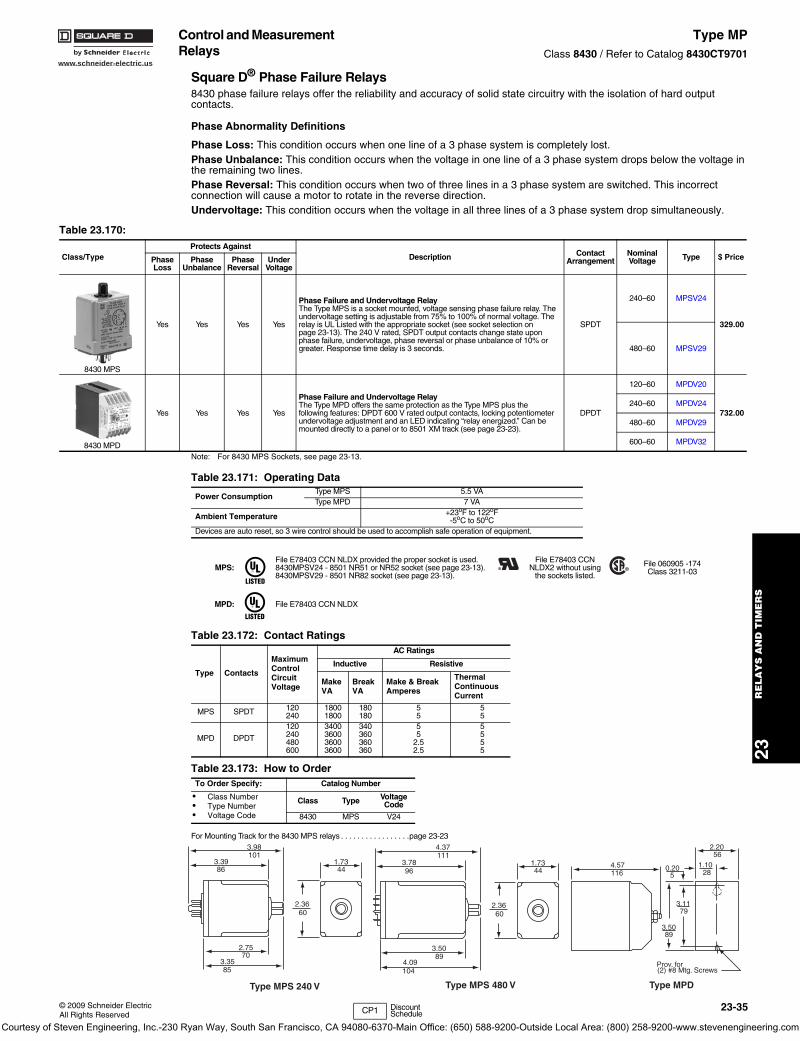
www.schneider-electric.us
23R
ELA
YS
AN
D T
IME
RS
© 2009 Schneider ElectricAll Rights Reserved
23-35
Control and Measurement Relays
Type MPClass 8430 / Refer to Catalog 8430CT9701
Square D® Phase Failure Relays8430 phase failure relays offer the reliability and accuracy of solid state circuitry with the isolation of hard output contacts.
Phase Abnormality Definitions
Phase Loss: This condition occurs when one line of a 3 phase system is completely lost.Phase Unbalance: This condition occurs when the voltage in one line of a 3 phase system drops below the voltage in the remaining two lines.Phase Reversal: This condition occurs when two of three lines in a 3 phase system are switched. This incorrect connection will cause a motor to rotate in the reverse direction.Undervoltage: This condition occurs when the voltage in all three lines of a 3 phase system drop simultaneously.
Note: For 8430 MPS Sockets, see page 23-13.
For Mounting Track for the 8430 MPS relays . . . . . . . . . . . . . . . . .page 23-23
Table 23.170:
Class/TypeProtects Against
Description ContactArrangement
Nominal Voltage Type $ PricePhase
LossPhase
UnbalancePhase
ReversalUnder
Voltage
8430 MPS
Yes Yes Yes Yes
Phase Failure and Undervoltage RelayThe Type MPS is a socket mounted, voltage sensing phase failure relay. The undervoltage setting is adjustable from 75% to 100% of normal voltage. The relay is UL Listed with the appropriate socket (see socket selection on page 23-13). The 240 V rated, SPDT output contacts change state upon phase failure, undervoltage, phase reversal or phase unbalance of 10% or greater. Response time delay is 3 seconds.
SPDT
240–60 MPSV24
329.00
480–60 MPSV29
8430 MPD
Yes Yes Yes Yes
Phase Failure and Undervoltage RelayThe Type MPD offers the same protection as the Type MPS plus the following features: DPDT 600 V rated output contacts, locking potentiometer undervoltage adjustment and an LED indicating “relay energized.” Can be mounted directly to a panel or to 8501 XM track (see page 23-23).
DPDT
120–60 MPDV20
732.00240–60 MPDV24
480–60 MPDV29
600–60 MPDV32
Table 23.171: Operating Data
Power ConsumptionType MPS 5.5 VAType MPD 7 VA
Ambient Temperature +23oF to 122oF-5oC to 50oC
Devices are auto reset, so 3 wire control should be used to accomplish safe operation of equipment.
MPS:File E78403 CCN NLDX provided the proper socket is used.8430MPSV24 - 8501 NR51 or NR52 socket (see page 23-13).8430MPSV29 - 8501 NR82 socket (see page 23-13).
File E78403 CCNNLDX2 without using
the sockets listed.
File 060905 -174Class 3211-03
MPD: File E78403 CCN NLDX
Table 23.172: Contact Ratings
Type Contacts
MaximumControlCircuitVoltage
AC Ratings
Inductive Resistive
MakeVA
BreakVA
Make & BreakAmperes
ThermalContinuousCurrent
MPS SPDT 120240
18001800
180180
55
55
MPD DPDT
120240480600
3400360036003600
340360360360
55
2.52.5
5555
Table 23.173: How to OrderTo Order Specify: Catalog Number
• Class Number• Type Number• Voltage Code
Class Type Voltage Code
8430 MPS V24
4.57116
0.205
2.2056
1.1028
3.1179
3.5089
Prov. for(2) #8 Mtg. Screws
Type MPD
3.98101
3.3986
2.7570
3.3585
2.3660
1.7344
Type MPS 240 V
4.37111
3.7896
3.5089
4.09104
2.3660
1.7344
Type MPS 480 V
CP1 Discount Schedule
Courtesy of Steven Engineering, Inc.-230 Ryan Way, South San Francisco, CA 94080-6370-Main Office: (650) 588-9200-Outside Local Area: (800) 258-9200-www.stevenengineering.com

www.schneider-electric.us
23R
EL
AY
S A
ND
TIM
ER
S
23-36 © 2009 Schneider ElectricAll Rights Reserved
Control and Measurement Relays
RC87610Refer to Catalog 9051CT0501
Zelio® CountersThis type of counter is typically used on simple machines to keep a running total of the number of cycles the machine has performed or the total amount of time that a machine has been running. This information can be very useful in a preventative maintenance program.
Totalizing CountersA totalizing counter is used to count electrical pulses or contact closings. The display will show the value and update this value after each pulse. They count up only and can be reset on the front of the device or remotely.
Hour Counters An hour counter is used to count the elapsed time and display the value. They count up only and can be reset on the front of the device or remotely.
Accessories These adaptors are used to mount above counters in holes other than 24x48 mm.
Approximate Dimensions
Table 23.174: Totalizing CountersDescription Catalog Number $ Price
24 x 48 mmTotalizing Counter
8 Digit LCD, 40 Hz input RC87610050 116.008 Digit LCD, 14 or 100 Hz input RC87610240 140.008 Digit LCD, 14 Hz input RC87610250 140.008 Digit LCD, 40 Hz or 7 kHz input RC87610340 42.30
Table 23.175: Hour CountersDescription Catalog Number $ Price
24 x 48mmTotalizing Counters
6 Digit LCD, 0–99,999.9 Hours Counted when voltage is applied RC87610150 116.006 Digit LCD, 0–99,999.9 Hours Counted when a contact is closed RC87610440 42.30
Table 23.176: Mounting Adapters
DescriptionDimensions
Catalog Number $ Pricein. mm
Adapters forpanel cut-out
0.98x1.96 25x50 RC26546829 5.001.77x1.77 45x45 RC26546830 5.00
1.96 diameter 50 diameter RC26546831 9.90
RC87610050
RC87610050
RC87610340
Table 23.177: How to Order
To Order Specify:
Catalog Number
• Catalog Number
RC87610050
FileCCN
E173076NRNT, NRNT7
FileClass
2176983211 07 IEC 61010
Table 23.178: RC87610050 RC87610240 / RC87610250
RC87610340 / RC87610440 RC87610150
Table 23.179: RC26546830Panel cut-out
0.94
(24)
1.47
(37.3)
0.13
(3.2)
1.89(48)
1.76(44.6)
0.86
(21.
8)
2108
1.89(48)
0.94
(2
4)
1.7644.6
0.86
(21.
8)
2.52
(64)
0.12
(3)
0.94
(24)
1.47
(37.3)
0.13
(3.2)
1.89(48)
1.76(44.6)
0.86
(21.
8)
2108
1.89(48)
1.76(44.6)
0.86
(21.
8)
0.94
(24)
2.52
(64)
0.12
(3)
0.79
(20)
1.18(30)
0.89
(22)
+ 0
,3 -
0 1.77(44.8)
+ 0,5 - 0
CP1 Discount Schedule
Courtesy of Steven Engineering, Inc.-230 Ryan Way, South San Francisco, CA 94080-6370-Main Office: (650) 588-9200-Outside Local Area: (800) 258-9200-www.stevenengineering.com
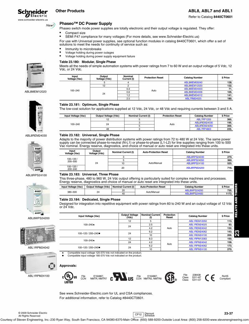
www.schneider-electric.us
23R
ELA
YS
AN
D T
IME
RS
© 2009 Schneider ElectricAll Rights Reserved
23-37
Other Products ABL8, ABL7 and ABL1Refer to Catalog 8440CT0601
Phaseo™ DC Power SupplyPhaseo switch mode power supplies are totally electronic and their output voltage is regulated. They offer:• Compact size• SEMI F47 compliance for many voltages (For more details, see www.Schneider-Electric.us)For use with Universal power supplies, see optional function modules in catalog 8440CT0601, which offer a set of solutions to meet the needs for continuity of service such as:• Immunity to microbreaks • Voltage holding during power outages • Voltage holding during power supply equipment failure
Table 23.184: Dedicated, Single PhaseDesigned for integration into repetitive equipment with power ratings from 60 to 240 W and an output voltage of 12 Vdc or 24 Vdc..
a Compatible input voltage 120-370 Vdc not indicated on the product.b Compatible input voltage 180-370 Vdc not indicated on the product.
Approvals:
See www.Schneider-Electric.com for UL and CSA compliances.For additional information, refer to Catalog #8440CT0601.
Table 23.180: Modular, Single PhaseMeets all the needs of simple automation systems with power ratings from 7 to 60 W and an output voltage of 5 Vdc, 12 Vdc, or 24 Vdc.
InputVoltage (Vac)
OutputVoltage (Vdc)
NominalCurrent (I) Protection Reset Catalog Number $ Price
100–240
5 4
Auto
ABL8MEM05040 128.12 2 ABL8MEM12020 132.
24
0.3 ABL8MEM24003 71.0.6 ABL8MEM24006 105.1.2 ABL8MEM24012 141.2.5 ABL7RM24025 180.
Table 23.181: Optimum, Single PhaseThe low-cost solution for applications supplied at 12 Vdc, 24 Vdc, or 48 Vdc and requiring currents between 3 and 5 A.
Input Voltage (Vac) Output Voltage (Vdc) Nominal Current (I) Protection Reset Catalog Number $ Price
100–240
12 5
Auto
ABL7RP1205 360.
243 ABL8REM24030 195.5 ABL8REM24050 300.
48 3 ABL7RP4803 225.
Table 23.182: Universal, Single PhaseAdapts to the majority of power distribution systems with power ratings from 72 to 480 W at 24 Vdc. The same power supply can be connected phase-to-neutral (N-L1) or phase-to-phase (L1-L2) for line supplies ranging from 100 to 500 Vac nominal. Energy reserve, diagnostics, and choice of manual or auto reset are integrated into these units.
Input Voltage (Vac)
Output Voltage (Vdc) Nominal Current (I) Auto-Protection Reset Catalog Number $ Price
100–120 / 200–500
24
3
Auto/Manual
ABL8RPS24030 270.5 ABL8RPS24050 360.
10 ABL8RPS24100 525.100–120 / 200–240 20 ABL8RPM24200 716.
Table 23.183: Universal, Three PhaseThis three-phase, 480 to 960 W, 24 Vdc output offering is particularly suited for complex machines and processes. Energy reserve, diagnostics and choice of manual or auto reset are integrated into these units.
Input Voltage (Vac) Output Voltage (Vdc) Nominal Current (I) Auto-Protection Reset Catalog Number $ Price
380–500 2420
Auto/ManualABL8WPS24200 735.
40 ABL8WPS24400 1173.
Input Voltage (Vac) Output Voltage (Vdc)
Nominal Current (I)
Protection Reset Catalog Number $ Price
100–240a12 5
Auto
ABL1REM12050 113.
242.5 ABL1REM24025 93.4.2 ABL1REM24042 132.
100–120 / 200–240b 246.2 ABL1REM24062 143.10 ABL1REM24100 206.
100–240a12 8.3
Auto
ABL1RPM12083 150.24 4.2 ABL1RPM24042 158.
100–120 / 200–240b 246.2 ABL1RPM24062 173.10 ABL1RPM24100 270.
FileCCN
E164867,NMTR, NMTR7
FileCCN
E164867,NMTR2, NMTR8
FileClassClass
2384385311-875311-07
RoHS Compliant
ABL8MEM12020
ABL8REM24030
ABL8RPS24100
ABL8WPS24200
ABL1RPM24042
ABL1RPM24100
CP12 Discount Schedule
New!
Courtesy of Steven Engineering, Inc.-230 Ryan Way, South San Francisco, CA 94080-6370-Main Office: (650) 588-9200-Outside Local Area: (800) 258-9200-www.stevenengineering.com
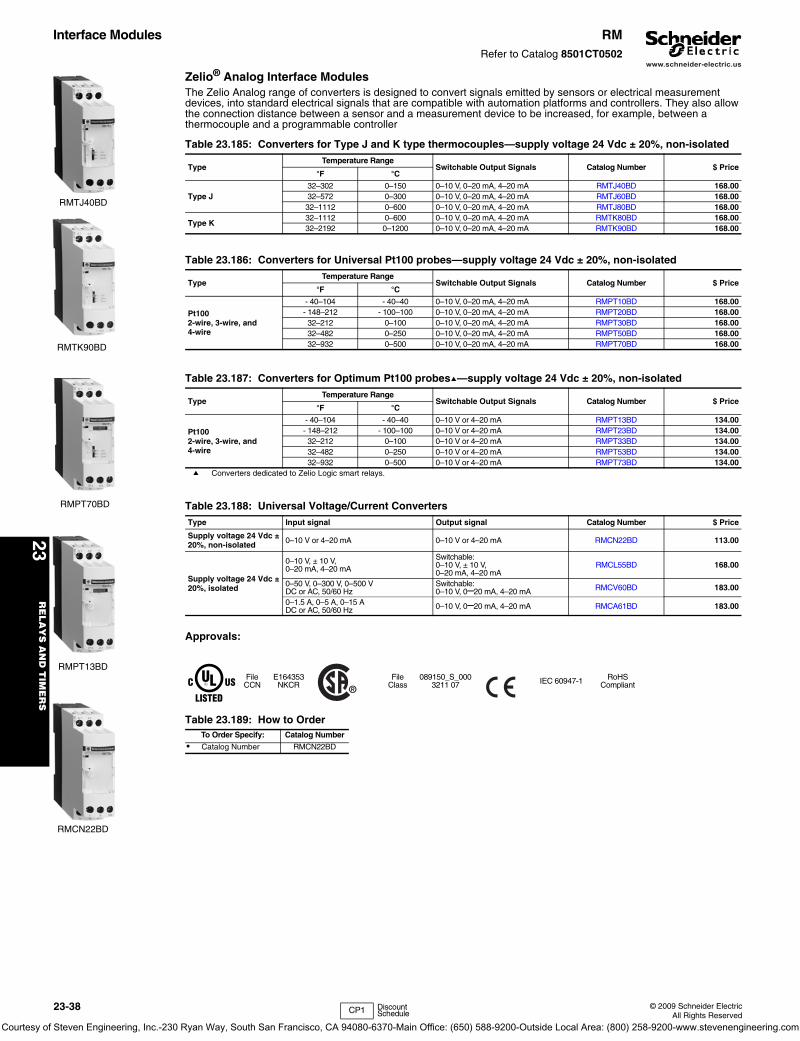
www.schneider-electric.us
23R
EL
AY
S A
ND
TIM
ER
S
23-38 © 2009 Schneider ElectricAll Rights Reserved
Interface Modules RMRefer to Catalog 8501CT0502
Zelio® Analog Interface ModulesThe Zelio Analog range of converters is designed to convert signals emitted by sensors or electrical measurement devices, into standard electrical signals that are compatible with automation platforms and controllers. They also allow the connection distance between a sensor and a measurement device to be increased, for example, between a thermocouple and a programmable controller
a Converters dedicated to Zelio Logic smart relays.
Approvals:
Table 23.185: Converters for Type J and K type thermocouples—supply voltage 24 Vdc ± 20%, non-isolated
TypeTemperature Range
Switchable Output Signals Catalog Number $ Price°F °C
Type J 32–302 0–150 0–10 V, 0–20 mA, 4–20 mA RMTJ40BD 168.0032–572 0–300 0–10 V, 0–20 mA, 4–20 mA RMTJ60BD 168.0032–1112 0–600 0–10 V, 0–20 mA, 4–20 mA RMTJ80BD 168.00
Type K 32–1112 0–600 0–10 V, 0–20 mA, 4–20 mA RMTK80BD 168.0032–2192 0–1200 0–10 V, 0–20 mA, 4–20 mA RMTK90BD 168.00
Table 23.186: Converters for Universal Pt100 probes—supply voltage 24 Vdc ± 20%, non-isolated
TypeTemperature Range
Switchable Output Signals Catalog Number $ Price°F °C
Pt1002-wire, 3-wire, and 4-wire
- 40–104 - 40–40 0–10 V, 0–20 mA, 4–20 mA RMPT10BD 168.00- 148–212 - 100–100 0–10 V, 0–20 mA, 4–20 mA RMPT20BD 168.0032–212 0–100 0–10 V, 0–20 mA, 4–20 mA RMPT30BD 168.0032–482 0–250 0–10 V, 0–20 mA, 4–20 mA RMPT50BD 168.0032–932 0–500 0–10 V, 0–20 mA, 4–20 mA RMPT70BD 168.00
Table 23.187: Converters for Optimum Pt100 probesa—supply voltage 24 Vdc ± 20%, non-isolated
TypeTemperature Range
Switchable Output Signals Catalog Number $ Price°F °C
Pt1002-wire, 3-wire, and 4-wire
- 40–104 - 40–40 0–10 V or 4–20 mA RMPT13BD 134.00- 148–212 - 100–100 0–10 V or 4–20 mA RMPT23BD 134.0032–212 0–100 0–10 V or 4–20 mA RMPT33BD 134.0032–482 0–250 0–10 V or 4–20 mA RMPT53BD 134.0032–932 0–500 0–10 V or 4–20 mA RMPT73BD 134.00
Table 23.188: Universal Voltage/Current ConvertersType Input signal Output signal Catalog Number $ Price
Supply voltage 24 Vdc ± 20%, non-isolated 0–10 V or 4–20 mA 0–10 V or 4–20 mA RMCN22BD 113.00
Supply voltage 24 Vdc ± 20%, isolated
0–10 V, ± 10 V,0–20 mA, 4–20 mA
Switchable:0–10 V, ± 10 V,0–20 mA, 4–20 mA
RMCL55BD 168.00
0–50 V, 0–300 V, 0–500 VDC or AC, 50/60 Hz
Switchable:0–10 V, 0–20 mA, 4–20 mA RMCV60BD 183.00
0–1.5 A, 0–5 A, 0–15 ADC or AC, 50/60 Hz 0–10 V, 0–20 mA, 4–20 mA RMCA61BD 183.00
FileCCN
E164353NKCR
FileClass
089150_S_0003211 07 IEC 60947-1 RoHS
Compliant
Table 23.189: How to OrderTo Order Specify: Catalog Number
• Catalog Number RMCN22BD
RMTJ40BD
RMTK90BD
RMPT70BD
RMPT13BD
RMCN22BD
CP1 Discount Schedule
Courtesy of Steven Engineering, Inc.-230 Ryan Way, South San Francisco, CA 94080-6370-Main Office: (650) 588-9200-Outside Local Area: (800) 258-9200-www.stevenengineering.com
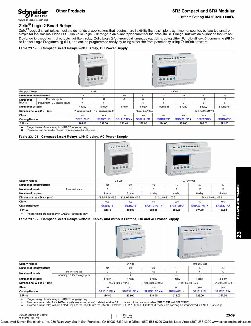
www.schneider-electric.us
23R
ELA
YS
AN
D T
IME
RS
© 2009 Schneider ElectricAll Rights Reserved
23-39
Other Products SR2 Compact and SR3 ModularRefer to Catalog DIA3ED2031108EN
Zelio® Logic 2 Smart RelaysZelio® Logic 2 smart relays meet the demands of applications that require more flexibility than a simple relay, timer, or counter, but are too small or simple for the smallest Nano PLC. The Zelio Logic SR2 range is an exact replacement for the obsolete SR1 range, but with an expanded feature set. Designed to accept control outputs just like a relay, Zelio Logic 2 features dual language capability, using either Function Block Diagramming (FBD) or Ladder Logic Programming (LL), and can be programmed easily by using either the front panel or by using ZelioSoft software.
Table 23.190: Compact Smart Relays with Display, DC Power Supply
Supply voltage 12 Vdc 24 Vdc
Number of inputs/outputs 12 20 10 12 12 20 20 20
Number of inputs
Discrete inputs 8 12 6 8 8 12 12 12Including 0-10 V analog inputs 4 6 — 4 4 2 6 6
Number of outputs 4 relay 8 relay 4 relay 4 relay 4 transistor 8 relay 8 relay 8 transistor
Dimensions, W x D x H (mm) 71.2x59.5x107.6 124.6x59.5x107.6 71.2x59.5x107.6 124.6x59.5x107.6
Clock yes yes no yes yes no yes yes
Catalog Number SR2B121JD SR2B201JD SR2A101BD c SR2B121BD SR2B122BD SR2A201BD c SR2B201BD SR2B202BD
$ Price 282.00 398.00 232.00 282.00 276.00 358.00 398.00 392.00
a Programming of smart relay in LADDER language only.b Please consult Schneider Electric representative for list prices.
Table 23.191: Compact Smart Relays with Display, AC Power Supply
Supply voltage 24 Vac 100–240 Vac
Number of inputs/outputs 12 20 10 12 20 20
Number of inputs Discrete inputs 8 12 6 8 12 12
Number of outputs 4 relay 8 relay 4 relay 4 relay 8 relay 8 relay
Dimensions, W x D x H (mm) 71.2x59.5x107.6 124.6x59.5x107.6 71.2 x 59.5 x 107.6 124.6 x 59.5 x 107.6
Clock yes yes no yes no yes
Catalog Number SR2B121B SR2B201B SR2A101FU a SR2B121FU SR2A201FU a SR2B201FU
$ Price 282.00 398.00 258.00 288.00 374.00 408.00
c Programming of smart relay in LADDER language only.
Table 23.192: Compact Smart Relays without Display and without Buttons, DC and AC Power Supply
Supply voltage 24 Vdc 100–240 Vac
Number of inputs/outputs 12 20 20 10 12 20
Number of inputsDiscrete inputs 6 8 12 6 8 12
Including 0-10 V analog inputs — 4 6 — — —
Number of outputs 4 relay 4 relay 8 relay 4 relay 4 relay 8 relay
Dimensions, W x D x H (mm) 71.2 x 59.5 x 107.6 124.6x59.5x107.6 71.2 x 59.5 x 107.6 124.6x59.5x107.6
Clock no yes yes no yes yes
Catalog Number SR2D101BD d SR2E121BD b SR2E201BD bc SR2D101FU d SR2E121FU SR2E201FUc
$ Price 214.00 222.00 338.00 218.00 226.00 344.00
d Programming of smart relay in LADDER language only.e To order a smart relay for a 24 Vac supply (no analog inputs), delete the letter D from the end of the catalog number (SR2E121B and SR2E201B).f To order a smart relay without a clock, replace the letter E with the letter D (Example: SR2D201BD and SR2D201FU (these units can only be programmed in LADDER language.
I Discount Schedule
Courtesy of Steven Engineering, Inc.-230 Ryan Way, South San Francisco, CA 94080-6370-Main Office: (650) 588-9200-Outside Local Area: (800) 258-9200-www.stevenengineering.com
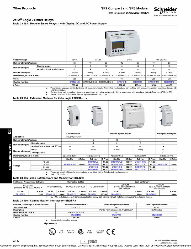
www.schneider-electric.us
23R
EL
AY
S A
ND
TIM
ER
S
23-40 © 2009 Schneider ElectricAll Rights Reserved
Other Products SR2 Compact and SR3 ModularRefer to Catalog DIA3ED2031108EN
yZelio® Logic 2 Smart Relays
a The modular base can be fitted with one I/O extension module. The 24 Vdc modular base can be fitted with one communication module and/or one I/O extension module.
b Replace the p by the number 1 to order a smart relay with relay output or by 2 for a smart relay with transistor output (Example: SR3B101BD).c Please consult local Schneider Electric representative for list prices.
a The power supply of the extension modules is provided via the Zelio Logic 2 modular relays.b max. 1 PT 100 input
a CD-ROM includes Zelio Soft software, application library, self-training manual, installation instructions and user’s manual
a Modems to be supplied by user.
Approvals:
Table 23.193: Modular Smart Relays a with Display, DC and AC Power Supply
Supply voltage 12 Vdc 24 Vdc 24Vac 100-240 Vac
Number of inputs/outputs 26 10 26 10 26 10 26
Number of inputsDiscrete inputs 16 6 16 6 16 6 16
Including 0-10 V analog inputs 6 4 6 — — — —
Number of outputs 10 relay 4 relay 10 relay 4 relay 10 relay 4 relay 10 relay
Dimensions, W x D x H (mm) 124.6x59.5x107.6 71.2x59.5x107.6 24.6x59.5x107.6 71.2x59.5x107.6 124.6x59.5x107.6 71.2x59.5x107.6 124.6x59.5x107.6
Clock yes yes yes yes yes yes yes
Catalog Number SR3B261JD SR3B10pBD bc SR3B26pBD bc SR3B101B SR3B261B SR3B101FU SR3B261FU
$ Price 380.00 — — 282.00 476.00 292.00 486.00
Table 23.194: Extension Modules for Zelio Logic 2 SR3B•••••a
Communication Discrete Inputs/Outputs Analog Inputs/Outputs
Application MODBUS network — —
Number of inputs/outputs — 6 10 14 4
Number of inputsDiscrete inputs — 4 6 8 —
Analog (0–10 V, 0–20 mA, PT100) — — — — 2b
Number of outputsRelay — 2relay 4 relay 6 relay —
Analog (0-10 V) — — — — 2
Dimensions, W x D x H (mm) 35.5x59.5x107.6 35.5x59.5x107.6 72x59.5x107.6 72x59.5x107.6 35.5x59.5x107.6
Cat. No. $ Price Cat. No. $ Price Cat. No. $ Price Cat. No. $ Price Cat. No. $ Price
Voltage
12 Vdc — — SR3XT61JD 80.00 SR3XT101JD 100.00 SR3XT141JD 140.00 — —24 Vdc SR3MBU01BD 200.00 SR3XT61BD 106.00 SR3XT101BD 126.00 SR3XT141BD 164.00 SR3XT43BD 220.0024 Vac — — SR3XT61B 106.00 SR3XT101B 126.00 SR3XT141B 164.00 — —
100-240 Vac — — SR3XT61FU 106.00 SR3XT101FU 126.00 SR3XT141FU 164.00 — —
Table 23.195: Zelio Soft Software and Memory for SR2/SR3Multilingual Programming Software Connecting Cables Back-up Memory
PCCD-ROM (Windows 98, NT, 2000, XP, ME) a PC Serial to Relay PC USB to SR2CBL01 PC USB to Relay
EEPROM (< V3.0 ZelioSoft software
and firmware)
EEPROM (≥V3.0 ZelioSoft software
and firmware)
Cat. No. $ Price Cat. No. $ Price Cat. No. $ Price Cat. No. $ Price Cat. No. $ Price Cat. No. $ Price
SR2SFT01 74.00 SR2CBL01 136.00 SR2CBL06 156.00 SR2USB01 160.00 SR2MEM01 38.00 SR2MEM02 30.00
Table 23.196: Communication interface for SR2/SR3Interface, Zelio Logic 2 Alarm Software Communication Interface a Alarm Management Software Zelio Logic GSM Modem
Supply voltage 12-24 Vdc — 24 VdcDescription — PC CD-ROM (Windows 98, NT, 2000, XP) GSM modemDimensions, W x D x H 72x59.5x107.6 mm —Catalog Number SR2COM01 SR2SFT02 SR2MOD02$ Price 230.00 60.00 545.00
FileCCN
E164866NRAQ
FileClass
LR2176982252 01
I Discount Schedule
Courtesy of Steven Engineering, Inc.-230 Ryan Way, South San Francisco, CA 94080-6370-Main Office: (650) 588-9200-Outside Local Area: (800) 258-9200-www.stevenengineering.com
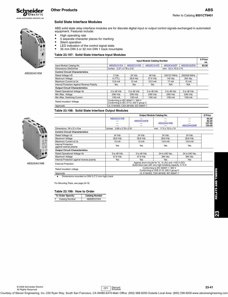
www.schneider-electric.us
23R
ELA
YS
AN
D T
IME
RS
© 2009 Schneider ElectricAll Rights Reserved
23-41
Other Products ABSRefer to Catalog 8501CT9401
Solid State Interface Modules
a Dimensions mounted on DIN 3 (7.5 mm high) track.
For Mounting Track, see page 24-16.
ABS solid state relay interface modules are for discrete digital input or output control signals exchanged in automated equipment. Features include:• High operating rate• 5 separate character places for marking• Silent operation• LED indication of the control signal state• 35 mm DIN 3 or 32 mm DIN 1 track mountable
Table 23.197: Solid State Interface Input Modules
Input Module Catalog Number $ Priceea.
Input Module Catalog No. ABS2EC01EA ABS2EC01EB ABS2EC01EE ABS2EA02EF ABS2EA02EM 83.00Dimensions (WxDxH)a Inches: 0.37 x 2.78 x 2.91 mm: 9.5 x 70.5 x 74
Control Circuit Characteristics
Rated Voltage US 5 Vdc 24 Vdc 48 Vdc 120/127 60Hz 230/240 60HzMaximum Voltage 6 (TTL) 28.8 Vdc 57.6 Vdc 140 Vac 264 VacMaximum Current at Us 13.6 mA 12 mA 10.5 mA 17 mA 15 mAInternal Protection Against Reverse Polarity Yes Yes Yes N/A N/A
Output Circuit Characteristics
Rated Operational Voltage Ve 5 to 48 Vdc 5 to 48 Vdc 5 to 48 Vdc 5 to 48 Vdc 5 to 48 VdcMin./Max. Voltage 2/60 Vdc 2/60 Vdc 2/60 Vdc 2/60 Vdc 2/60 VdcMin./Max. Switching Current 1/50 mA 1/50 mA 1/50 mA 1/50 mA 1/50 mA
Rated Insulation Voltage Conforming to IEC 60947-1: 300 VConforming to IEC 0110: 250 V group C
Approvals UL E164353, CSA 081630, IEC 60947-1
Table 23.198: Solid State Interface Output ModulesOutput Module Catalog No. $ Price
ABS2SC01EB———
—ABS2SC02EB
——
——
ABS2SA01MB—
———
ABS2SA02MB
95.0095.00
107.00120.00
Dimensions (W x D x H)a Inches: 0.69 x 2.78 x 2.91 mm: 17.5 x 70.5 x 74
Control Circuit Characteristics
Rated Voltage Us 24 Vdc 24 Vdc 24 Vdc 24 VdcMaximum Voltage 28.8 Vdc 28.8 Vdc 28.8 Vdc 28.8 VdcMaximum Current at Us 12 mA 12 mA 13.6 mA 13.6 mAInternal Protectionagainst reverse polarity Yes Yes Yes Yes
Output Circuit Characteristics
Rated Operational Voltage Ve 5 to 48 Vdc 5 to 48 Vdc 24 to 240 Vac 24 to 240 VacMaximum Voltage 57.6 Vdc 57.6 Vdc 264 Vac 264 VacInternal Protection against reverse polarity Yes Yes Yes Yes
External Protection Against short-circuits for 1k, 1k (Ac) and <100 A (DC)Quick-blow fuse with very high breaking capacity: 3.15 A
Rated insulation voltage Conforming to IEC 60947-1: 300 VConforming to VDE 0110: 250 V group C
Approvals UL E164353, CSA 081630, IEC 60947-1
Table 23.199: How to OrderTo Order Specify: Catalog Number
• Catalog Number ABS2EC01EA
ABS2EA01EM
ABS2SA01MB
CP1 Discount Schedule
Courtesy of Steven Engineering, Inc.-230 Ryan Way, South San Francisco, CA 94080-6370-Main Office: (650) 588-9200-Outside Local Area: (800) 258-9200-www.stevenengineering.com

www.schneider-electric.us
23R
EL
AY
S A
ND
TIM
ER
S
23-42 © 2009 Schneider ElectricAll Rights Reserved
Other Products ABRRefer to Catalog 8501CT9401
Electromechanical Interface ModulesABR electromechanical relay modules are for discrete digital input or output control signals exchanged in automated equipment. Features include:• High contact reliability• LED indication of the control signal state• 5 separate character places for marking• 35 mm DIN 3 or 32 mm DIN 1 track mountable
a RoHS Compliant
b RoHS Compliant
c Dimensions mounted on DIN 3 track (7.5 mm high).
ABR1 relays are RoHS compliant as of date code 0610.
For Mounting Track, see page 24-16
Table 23.200: Input Modules
Coil Voltage Options1 N.O. Contact 1 C.O. Contact 2 N.O. Contacts
$ PriceCatalog Number Catalog Number Catalog Number
24 Vac/Vdc
Manual Operator andLED Indication
ABR1E118Ba ABR1E318Ba ABR1E418Ba
81.00
48 Vac/Vdc ABR1E118Ea ABR1E318Ea ABR1E418Ea110–125 Vdc ABR1E112Fa ABR1E312Fa ABR1E412Fa110–127 Vac 50/60 Hz ABR1E111Fa ABR1E311Fa ABR1E411Fa230–240 Vac 50/60 Hz ABR1E111Ma ABR1E311Ma ABR1E411Ma230–240 Vac 50/60 Hz Manual Operator ABR1E101Ma ABR1E301Ma —24 Vdc
LED Indication
ABR2E112B — —62.00
48 Vdc ABR2E112E — —120–127 Vac 60 Hz ABR2E116F — —
71.00230–240 Vac 50/60 Hz ABR2E111M — —24 Vdc — ABR2EB312B — 90.00
Table 23.201: Output Modules
Coil Voltage Options1 N.O. Contact 1 C.O. Contact 2 N.O. Contacts 1 N.C. & 1 N.O. Contact
$ PriceCatalog Number Catalog Number Catalog Number Catalog Number
24 Vdc Manual Operator ABR1S102Bb ABR1S302Bb ABR1S402Bb ABR1S602Bb 62.0024 Vac/Vdc
Manual Operator andLED Indication
ABR1S118Bb ABR1S318Bb ABR1S418Bb ABR1S618Bb83.0048 Vac/Vdc ABR1S118Eb ABR1S318Eb ABR1S418Eb ABR1S618Eb
110–127 Vac 50/60 Hz ABR1S111Fb ABR1S311Fb ABR1S411Fb ABR1S611Fb24 Vdc
LED IndicationABR2S112B — — — 47.60
48 Vdc — ABR2SB312B — — 95.0024 Vdc — ABR2S102B — — — 30.90
Table 23.202: Coil DataRelay ABR1E ABR2E ABR2EB ABR1S ABR2S ABR2SB
Coil Voltage Ue V 24 Vac/Vdc
48 Vac/Vdc
127 Vdc
127 Vac
240 Vac
24 Vdc 48 Vdc 127
Vac240 Vac 24 Vdc 24
Vdc24
Vdc48
Vac/Vdc127 Vac 24 24 24
Maximum Voltage V 30 53 137 140 255 28.8 56 140 264 28.8 30 30 53 140 28.8 28.8 28.8
Pick-up Voltage V 17 38 97 93 195 16.9 37.3 97 186 16.9 17 17 38 83 16.9 16.9 16.9
Minimum Sealed Current mA 5.2 5.4 1.5 2.4 2 2 2 2.5 2.5 2 6.6 6.2 5.4 2.4 2 2 2
Maximum Sealed Current mA 62 36 15 8 7 19.5 11 16 15 29 62 62 36 8 28 17 29
Table 23.203: Contact RatingsRelay ABR1E ABR2E ABR2EB ABR1S ABR2S ABR2SB
Rated Voltage Ue Vac 250 115 48 250 230 48Rated Voltage Ue Vdc 125 100 48 125 120 48Thermal Current Ith A 2 1 0.05 5 5 0.05Break Rating (AC14) A 1 0.5 1 1 1 —Break Rating (DC13) A 1 1 1 1 1.5 —
Table 23.204: Dimensions
ModulesApproximate Dimensions (WxDxH)c
In. mm
ABR1E, ABR2EB, ABR2SB 0.69 x 2.91 x 2.78 17.5 x 74 x 70.5ABR2E 0.37 x 2.91 x 2.78 9.5 x 74 x 70.5ABR2S1 0.47 x 2.91 x 2.78 12 x 74 x 70.5
Table 23.205: ApprovalsABR1E, ABR2E UL E164353, CSA 081630, IEC 60947-1ABR1S, ABR2S UL E164353, CSA 081630, IEC 60947-1
ABR1E411F
ABR2E112E
ABR1S111F
ABR2S102B
CP1 Discount Schedule
Courtesy of Steven Engineering, Inc.-230 Ryan Way, South San Francisco, CA 94080-6370-Main Office: (650) 588-9200-Outside Local Area: (800) 258-9200-www.stevenengineering.com