table of contents - panasonic industrial devices europe gmbh
TRANSCRIPT

CLASSIFICATION PRODUCT SPECIFICATION No. DS-9020-2400-102
REV. 1.2
SUBJECT WI-FI IEEE 802.11 BGN RADIO MODULE PAGE 1 of 47
CUSTOMER’S CODE PAN9020U/10U & PAN9020S/10S
PANASONIC’S CODE ENW49801x1JF & ENW49802x1JF
DATE 31.07.2015
Power Electronics R&D Center Wireless Connectivity
Panasonic Industrial Devices Europe GmbH
APPROVED genehmigt
CHECKED geprüft
DESIGNED erstellt
Product Specification
Applicant / Manufacturer
Hardware
Panasonic Industrial Devices Europe GmbH
Zeppelinstrasse 19
21337 Lüneburg
Germany
Applicant / Manufacturer
Software
Please refer to chapter 30 / 30.1 Information regarding Software
Versions
Software Version Please refer to chapter 30 / 30.1 Information regarding Software
Versions
By purchase of any of products described in this document the customer accepts the document's validity and declares their agreement and understanding of its contents and recommendations. Panasonic reserves the right to make changes as required without notification.

CLASSIFICATION PRODUCT SPECIFICATION No. DS-9020-2400-102
REV. 1.2
SUBJECT WI-FI IEEE 802.11 BGN RADIO MODULE PAGE 2 of 47
CUSTOMER’S CODE PAN9020U/10U & PAN9020S/10S
PANASONIC’S CODE ENW49801x1JF & ENW49802x1JF
DATE 31.07.2015
PANASONIC INDUSTRIAL DEVICES EUROPE GMBH www.pideu.panasonic.de
TABLE OF CONTENTS
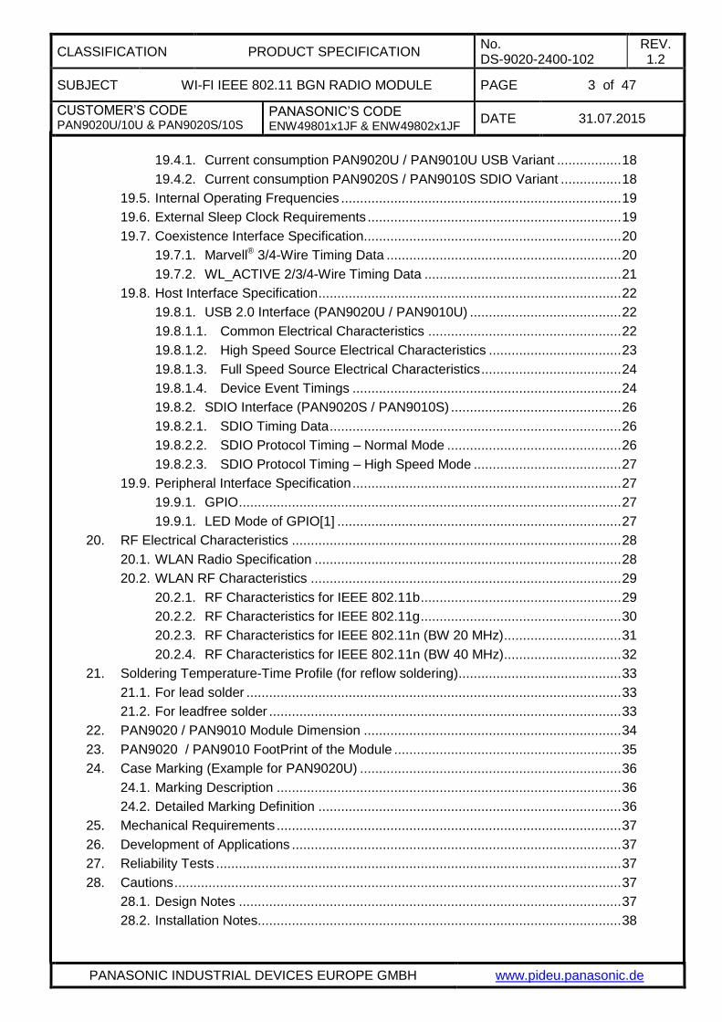
1. Scope of this Document ................................................................................................ 5
2. History for this Document .............................................................................................. 5
3. Data Sheet Status ......................................................................................................... 5
4. Related Documents ....................................................................................................... 5
5. Key Features ................................................................................................................. 6
6. Applications for the Module ........................................................................................... 6
7. Wireless Local Area Network ........................................................................................ 7
8. Description for the Module ............................................................................................. 8
9. Difference PAN9020U (USB) to PAN9020S (SDIO) ...................................................... 8
10. Difference PAN9020 to PAN9010 .................................................................................. 8
11. Detailed Description ...................................................................................................... 9
11.1. PAN9020 / PAN9010 Terminal Layout ................................................................. 9
11.2. PAN9020 / PAN9010 Common Terminal Pin-Configuration ............................... 10
11.3. PAN9020U / PAN9010U USB Specific Terminal Pin-Configuration ................... 10
11.4. PAN9020S / PAN9010S SDIO Specific Terminal Pin-Configuration .................. 10
11.5. PAN9010U / PAN9010S RF-Terminal Pin-Configuration ................................... 10
12. General Features ........................................................................................................ 11
13. HOST Interfaces ......................................................................................................... 11
13.1. PAN9020U / PAN9010U USB Variant ............................................................... 11
13.2. PAN9020S / PAN9010S SDIO Variant .............................................................. 11
14. Peripheral Bus Interface .............................................................................................. 11
15. WLAN Features ........................................................................................................... 12
15.1. IEEE 802.11 / Standards .................................................................................... 12
15.2. WLAN MAC ........................................................................................................ 12
15.3. WLAN Baseband ................................................................................................ 12
15.4. WLAN Radio ...................................................................................................... 13
15.5. WLAN Encryption ............................................................................................... 13
16. PAN9020U / PAN9010U Block Diagram ...................................................................... 14
16.1. PAN9020U USB Variant .................................................................................... 14
16.2. PAN9020S SDIO Variant .................................................................................. 14
16.3. PAN9010U USB Variant .................................................................................... 15
16.4. PAN9010S SDIO Variant .................................................................................. 15
17. Key Parts List .............................................................................................................. 16
18. Test Conditions ........................................................................................................... 16
19. General Requirements and Operation ......................................................................... 17
19.1. Absolute Maximum Ratings ................................................................................ 17
19.2. Recommended Operating Conditions ................................................................. 17
19.3. Digital Pin Characteristics .................................................................................. 17
19.4. Electrical characeristics ...................................................................................... 18
CLASSIFICATION PRODUCT SPECIFICATION No. DS-9020-2400-102
REV. 1.2
SUBJECT WI-FI IEEE 802.11 BGN RADIO MODULE PAGE 3 of 47
CUSTOMER’S CODE PAN9020U/10U & PAN9020S/10S
PANASONIC’S CODE ENW49801x1JF & ENW49802x1JF
DATE 31.07.2015
PANASONIC INDUSTRIAL DEVICES EUROPE GMBH www.pideu.panasonic.de
19.4.1. Current consumption PAN9020U / PAN9010U USB Variant ................. 18
19.4.2. Current consumption PAN9020S / PAN9010S SDIO Variant ................ 18
19.5. Internal Operating Frequencies .......................................................................... 19
19.6. External Sleep Clock Requirements ................................................................... 19
19.7. Coexistence Interface Specification.................................................................... 20
19.7.1. Marvell® 3/4-Wire Timing Data .............................................................. 20
19.7.2. WL_ACTIVE 2/3/4-Wire Timing Data .................................................... 21
19.8. Host Interface Specification ................................................................................ 22
19.8.1. USB 2.0 Interface (PAN9020U / PAN9010U) ........................................ 22
19.8.1.1. Common Electrical Characteristics ................................................... 22
19.8.1.2. High Speed Source Electrical Characteristics ................................... 23
19.8.1.3. Full Speed Source Electrical Characteristics ..................................... 24
19.8.1.4. Device Event Timings ....................................................................... 24
19.8.2. SDIO Interface (PAN9020S / PAN9010S) ............................................. 26
19.8.2.1. SDIO Timing Data ............................................................................. 26
19.8.2.2. SDIO Protocol Timing – Normal Mode .............................................. 26
19.8.2.3. SDIO Protocol Timing – High Speed Mode ....................................... 27
19.9. Peripheral Interface Specification ....................................................................... 27
19.9.1. GPIO ..................................................................................................... 27
19.9.1. LED Mode of GPIO[1] ........................................................................... 27
20. RF Electrical Characteristics ....................................................................................... 28
20.1. WLAN Radio Specification ................................................................................. 28
20.2. WLAN RF Characteristics .................................................................................. 29
20.2.1. RF Characteristics for IEEE 802.11b ..................................................... 29
20.2.2. RF Characteristics for IEEE 802.11g ..................................................... 30
20.2.3. RF Characteristics for IEEE 802.11n (BW 20 MHz) ............................... 31
20.2.4. RF Characteristics for IEEE 802.11n (BW 40 MHz) ............................... 32
21. Soldering Temperature-Time Profile (for reflow soldering) ........................................... 33
21.1. For lead solder ................................................................................................... 33
21.2. For leadfree solder ............................................................................................. 33
22. PAN9020 / PAN9010 Module Dimension .................................................................... 34
23. PAN9020 / PAN9010 FootPrint of the Module ............................................................ 35
24. Case Marking (Example for PAN9020U) ..................................................................... 36
24.1. Marking Description ........................................................................................... 36
24.2. Detailed Marking Definition ................................................................................ 36
25. Mechanical Requirements ........................................................................................... 37
26. Development of Applications ....................................................................................... 37
27. Reliability Tests ........................................................................................................... 37
28. Cautions ...................................................................................................................... 37
28.1. Design Notes ..................................................................................................... 37
28.2. Installation Notes ................................................................................................ 38
CLASSIFICATION PRODUCT SPECIFICATION No. DS-9020-2400-102
REV. 1.2
SUBJECT WI-FI IEEE 802.11 BGN RADIO MODULE PAGE 4 of 47
CUSTOMER’S CODE PAN9020U/10U & PAN9020S/10S
PANASONIC’S CODE ENW49801x1JF & ENW49802x1JF
DATE 31.07.2015
PANASONIC INDUSTRIAL DEVICES EUROPE GMBH www.pideu.panasonic.de
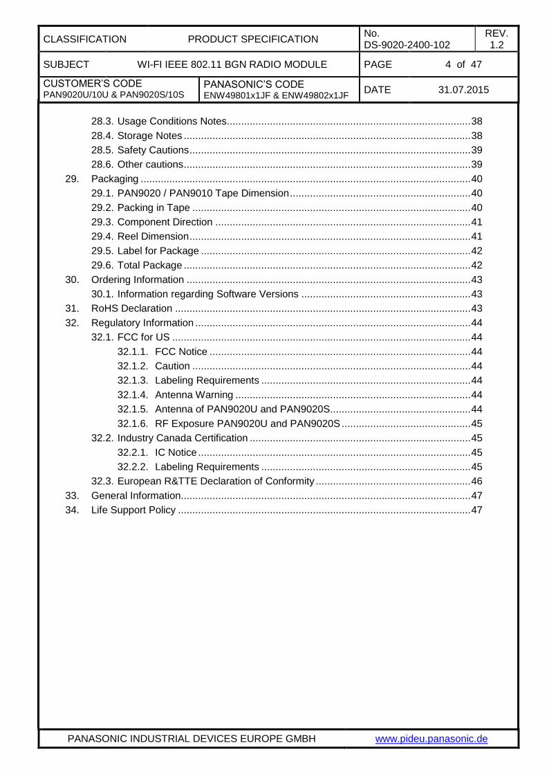
28.3. Usage Conditions Notes ..................................................................................... 38
28.4. Storage Notes .................................................................................................... 38
28.5. Safety Cautions .................................................................................................. 39
28.6. Other cautions .................................................................................................... 39
29. Packaging ................................................................................................................... 40
29.1. PAN9020 / PAN9010 Tape Dimension ............................................................... 40
29.2. Packing in Tape ................................................................................................. 40
29.3. Component Direction ......................................................................................... 41
29.4. Reel Dimension .................................................................................................. 41
29.5. Label for Package .............................................................................................. 42
29.6. Total Package .................................................................................................... 42
30. Ordering Information ................................................................................................... 43
30.1. Information regarding Software Versions ........................................................... 43
31. RoHS Declaration ....................................................................................................... 43
32. Regulatory Information ................................................................................................ 44
32.1. FCC for US ........................................................................................................ 44
32.1.1. FCC Notice ........................................................................................... 44
32.1.2. Caution ................................................................................................. 44
32.1.3. Labeling Requirements ......................................................................... 44
32.1.4. Antenna Warning .................................................................................. 44
32.1.5. Antenna of PAN9020U and PAN9020S................................................. 44
32.1.6. RF Exposure PAN9020U and PAN9020S ............................................. 45
32.2. Industry Canada Certification ............................................................................. 45
32.2.1. IC Notice ............................................................................................... 45
32.2.2. Labeling Requirements ......................................................................... 45
32.3. European R&TTE Declaration of Conformity ...................................................... 46
33. General Information ..................................................................................................... 47
34. Life Support Policy ...................................................................................................... 47

CLASSIFICATION PRODUCT SPECIFICATION No. DS-9020-2400-102
REV. 1.2
SUBJECT WI-FI IEEE 802.11 BGN RADIO MODULE PAGE 5 of 47
CUSTOMER’S CODE PAN9020U/10U & PAN9020S/10S
PANASONIC’S CODE ENW49801x1JF & ENW49802x1JF
DATE 31.07.2015
PANASONIC INDUSTRIAL DEVICES EUROPE GMBH www.pideu.panasonic.de
1. SCOPE OF THIS DOCUMENT
This product specification applies to Panasonic’s Wi-Fi IEEE 802.11 b/g/n radio module with model names PAN9020U, PAN9010U, PAN9020S and PAN9010S.
2. HISTORY FOR THIS DOCUMENT
3. DATA SHEET STATUS
This data sheet contains the PRELIMINARY specification. Supplementary data will be published at a later date.
Panasonic reserves the right to make changes at any time without notice in order to improve design and supply the best possible product.
Please consult the most recently issued data sheet before initiating or completing a design.
4. RELATED DOCUMENTS
For an update, please search in the suitable homepage.
[1] PAN9020U and PAN9020S Reference-Guide
[2] Semiconductor Datasheet
88W8782U from Marvell®
88W8782 from Marvell®
[3] Application Note Land Grid Array http://www.pideu.panasonic.de/pdf/184ext.pdf
[4] REACH and RoHS Certificate http://pideu.panasonic.de/files/Documents/WM-REACH_and_RoHS_directive.pdf
Revision Date Modification / Remarks
0.1 May 2014 1st preliminary version
0.2 May 2014 - Add Host Interface specification for USB 2.0 and SDIO (19.8 Host Interface Specification)
0.3 July 2014
- Change order of chapters, move 3. Data Sheet Status, 4. Related Documents, 9. Difference PAN9020U (USB) to PAN9020S (SDIO and 10. Difference PAN9020 to PAN9010, restructure chapter numbers
- Add contents of 802.11n - Supported data rates (20.1 WLAN Radio Specification)
- Change parameter information of EVM and Minimum Receiver Sensitivity (20.2.2 / 20.2.3 / 20.2.4)
0.4 October 2014
- Adapt Active Transmit Current (19.4.1)
- Add Transmit output power vs datarate and Carrier Frequency Tolerance at RF Characteristics for 802.11g (20.2.2) and 802.11n BW 20/40 MHz (20.2.3 / 20.2.4)
- Update comments at sub-chapters of Regulatory Information (32.)
- Adapt list of standards at European R&TTE Declaration of Conformity (32.3)
1.0 January 2015 - Adapt Case-marking information regarding FCC / IC certification (24)
1.1 January 2015 - Adapt specification based on change of model name PAN9020U/10U and PAN9020S/10S
1.2 July 2015
- SDIO specific Terminal Pin Configuration (11.4) - take out SPI mode
- Case-marking information regarding FCC / IC certification (24)
- Regulatory Information for FCC US (32.1 / 32.1.1 ~ 32.1.6)

CLASSIFICATION PRODUCT SPECIFICATION No. DS-9020-2400-102
REV. 1.2
SUBJECT WI-FI IEEE 802.11 BGN RADIO MODULE PAGE 6 of 47
CUSTOMER’S CODE PAN9020U/10U & PAN9020S/10S
PANASONIC’S CODE ENW49801x1JF & ENW49802x1JF
DATE 31.07.2015
PANASONIC INDUSTRIAL DEVICES EUROPE GMBH www.pideu.panasonic.de
5. KEY FEATURES
Surface Mount Type 22.75 x 13.5 x 2.4 mm³
Wireless Local Area Network (WLAN) Technology
Operating in the 2.4GHz ISM band
Supports IEEE 802.11 IEEE 802.11b/g payload data rates IEEE 802.11n high throughput data rates IEEE 802.11i security standards AES-CCMP, WEP, TKIP, AES-CMAC and WAPI IEEE 802.11e Quality of Service (QoS)
Coexistence Interface for external co-located 2.4GHz radios (e.g. Bluetooth)
Tx power up to +18 dBm (IEEE 802.11b CCK) and +15 dBm (IEEE 802.11g ODFM)
High Rx sensitivity -98dBm (IEEE 802.11b DSSS 1Mbps) -76dBm (IEEE 802.11g OFDM 54Mbps) -74dBm (IEEE 802.11n MCS7 HT20 65Mbps) -71dBm (IEEE 802.11n MCS7 HT40 135Mbps)
Marvell® 88W8782 WLAN System-on-Chip (SoC) solution inside
High performance low power CPU core
Two powerful independent DMA channels
Power Management Unit with internal or external Sleep Clock (for Power Save Mode)
Internal crystal oscillator (40MHz)
USB2.0 or SDIO interface
Integrated shielding to resist EMI
Manufactured in conformance with RoHS
6. APPLICATIONS FOR THE MODULE
All Embedded Wireless Applications
Imaging Platform Printer, Digital Picture Frame
Gaming Platform Game Console
Consumer Electronic TV, Media Player
Portable Application PC, Tablet, eBook
Health & Fitness Home Gateways, Medical devices
Smart Energy Thermostat, Control panels

CLASSIFICATION PRODUCT SPECIFICATION No. DS-9020-2400-102
REV. 1.2
SUBJECT WI-FI IEEE 802.11 BGN RADIO MODULE PAGE 7 of 47
CUSTOMER’S CODE PAN9020U/10U & PAN9020S/10S
PANASONIC’S CODE ENW49801x1JF & ENW49802x1JF
DATE 31.07.2015
PANASONIC INDUSTRIAL DEVICES EUROPE GMBH www.pideu.panasonic.de
7. WIRELESS LOCAL AREA NETWORK
Wireless Local Area Network (WLAN) is indicating a local radio network meant as a part of the standard IEEE 802.11 family. The IEEE 802.11 is an international standard describing the wireless network. The standard defines the lower layers of the OSI model for wireless communication with the Physical Layer (PHY) and the Data Link Layer (DLL) with its two sub-layers Logical Link Control (LLC) and Media Access Control (MAC). It makes it possible to use any protocol over a IEEE 802.11 wireless network as used at an Ethernet network. Basically WLAN networks using two operating modes for connecting station computers (STA) equipped with a wireless network adapter. The first one is the infrastructure mode where the wireless clients are connected via one or more access points (AP) to a wired network. In this case the network is configured with the same Service Set Identifier (SSID) network name in order to communicate. The second one is the Ad-hoc mode where wireless clients are connected without any access point to the internet.
WLAN devices typically have a higher transmit power to cover a radio range about 100m. Furthermore WLAN is commonly used to transmit high throughput data using upon other the Orthogonal Frequency Division Multiplexing (OFDM) modulation technique. The Carrier Sense Multiple Access with Collosion Avoidance (CSMA/CA) mechanism enables the parallel access of more than one device to the media of a IEEE 802.11 network. By implementation of security mechanisms like Adavanced Encryption Standard (AES) with Counter Mode CBC-MAC Protocol (CCMP) or Cipher-Based Message Authentication Code (CMAC) and Wired Equivalent Privacy (WEP) with Temporal Key Integrity Protocol (TKIP) the network is supporting the security standard IEEE 802.11i. Video, voice and multimedia applications are supported by the IEEE 802.11e Quality of Service amendment.

CLASSIFICATION PRODUCT SPECIFICATION No. DS-9020-2400-102
REV. 1.2
SUBJECT WI-FI IEEE 802.11 BGN RADIO MODULE PAGE 8 of 47
CUSTOMER’S CODE PAN9020U/10U & PAN9020S/10S
PANASONIC’S CODE ENW49801x1JF & ENW49802x1JF
DATE 31.07.2015
PANASONIC INDUSTRIAL DEVICES EUROPE GMBH www.pideu.panasonic.de
8. DESCRIPTION FOR THE MODULE
The PAN9020 series is a 2.4GHz ISM band wireless radio module for implementing WLAN functionality into various electronic devices. A block diagram can be found in chapter 16.
The PAN9020 series is a cost-effective, low-power operation, system-on-chip (SoC) solution for WLAN applications. It enables wireless network adapters and cards to be built with low total bill-of-material costs. The PAN9020 series combines an excellent 802.11 wireless radio, baseband processor, medium access controller, encryption unit, CPU, boot ROM with patching capability, internal SRAM, in-system programmable flash memory and many other powerful supporting features and peripherals. The low-power operation supporting deep sleep and standby modes by using the on-board power management unit. The PAN9020/10 is suitable for wireless network systems based on WLAN IEEE 802.11 b/g/n 2.4GHz where small form factor, highly integration, high throughput data rates and low RF expertise are required.
Panasonic offers the software package supporting various Fedora Core Kernel versions. It includes the WLAN SoC Firmware binary that powers the WLAN SoC for client (STA), micro access point (uAP) and Ad-hoc mode (Wi-Fi direct) applications. In addition it includes the HOST Driver-Firmware Interface (API) which represents the interface between the host driver and SoC firmware.
The Driver-Firmware Interface handles all 802.11 MAC management tasks by converting standard 802.3 frames to the SoC firmware to transmit over the wireless link as 802.11 frames and processes the received 802.11 frames and converts them into 802.3 frames before forwarding them to the host driver. The HOST driver is seperated in three modules. The Standard Ethernet driver, the 802.11 Extensions and the Hardware Interface Driver. The 802.11 Extensions module extends the Standard Ethernet driver in order to view and control the state of the WLAN adapter. The Hardware Interface Driver controls the hardware interface on the HOST side. Furtheron the software package from Marvell
® consists of various applications,
demonstrations and utilities.
Refer to [1] PAN9020U and PAN9020S Reference-Guide and chapter 30 Ordering Information.
Please contact your local sales office for further details on additional options and services:
http://na.industrial.panasonic.com/products/wireless-connectivity for the US,
http://eu.industrial.panasonic.com/products/wireless-connectivity for EU
or write an e-mail to [email protected].
9. DIFFERENCE PAN9020U (USB) TO PAN9020S (SDIO)
Both the PAN9020U (USB) and PAN9020S (SDIO) are refered to the PAN9020 series in this document.
The PAN9020U is pin-compatible with the PAN9020S, with the exception that USB is the hardware communication interface on the PAN9020U and SDIO is the hardware communication interface on the PAN9020S. The PAN9020S does not have the USB interface found on the PAN9020U. The RF performance on both PAN9020U and PAN9020S are the same.
Additional details, which have an impact on the module can be found in the datasheets from Marvell®.
88W8782U from Marvell®
88W8782 from Marvell®
10. DIFFERENCE PAN9020 TO PAN9010
The PAN9010 is the non antenna version with bottom pad where the PAN9020 is the version with antenna.

CLASSIFICATION PRODUCT SPECIFICATION No. DS-9020-2400-102
REV. 1.2
SUBJECT WI-FI IEEE 802.11 BGN RADIO MODULE PAGE 9 of 47
CUSTOMER’S CODE PAN9020U/10U & PAN9020S/10S
PANASONIC’S CODE ENW49801x1JF & ENW49802x1JF
DATE 31.07.2015
PANASONIC INDUSTRIAL DEVICES EUROPE GMBH www.pideu.panasonic.de
11. DETAILED DESCRIPTION
11.1. PAN9020 / PAN9010 TERMINAL LAYOUT
PAN9020U USB pins are marked with a blue rectangular box.
PAN9020S SDIO pins are marked with a blue dashed rectangular box.
PAN9010U and PAN9010S antenna pin is marked with a blue circle.
Top View, Application PCB

CLASSIFICATION PRODUCT SPECIFICATION No. DS-9020-2400-102
REV. 1.2
SUBJECT WI-FI IEEE 802.11 BGN RADIO MODULE PAGE 10 of 47
CUSTOMER’S CODE PAN9020U/10U & PAN9020S/10S
PANASONIC’S CODE ENW49801x1JF & ENW49802x1JF
DATE 31.07.2015
PANASONIC INDUSTRIAL DEVICES EUROPE GMBH www.pideu.panasonic.de
11.2. PAN9020 / PAN9010 COMMON TERMINAL PIN-CONFIGURATION
11.3. PAN9020U / PAN9010U USB SPECIFIC TERMINAL PIN-CONFIGURATION
11.4. PAN9020S / PAN9010S SDIO SPECIFIC TERMINAL PIN-CONFIGURATION
11.5. PAN9010U / PAN9010S RF-TERMINAL PIN-CONFIGURATION
No Pin Name Pin Type Description
1 GND Ground Pin Connect to Ground
2-7 … … … for USB see chapter 0 and for SDIO see chapter 11.4
8 GND Ground Pin Connect to Ground
9 PDn Input Signal Power down, active-low
10 GPIO[5] Digital I/O Port 5 – optional GPIO or W1_CNTL for PMD programming I/F control
11 GND Ground Pin Connect to Ground
12 GND Ground Pin Connect to Ground
13 GND Ground Pin Connect to Ground
14 GND Ground Pin Connect to Ground
15 NC NC … for PAN9010 see chapter 11.5
16 GND Ground Pin Connect to Ground
17 GND Ground Pin Connect to Ground
18 GND Ground Pin Connect to Ground
19 GND Ground Pin Connect to Ground
20 GND Ground Pin Connect to Ground
21 RESETn Input Signal Reset, active-low
22 GND Ground Pin Connect to Ground
23 GPIO[0] Digital I/O Port 0 – GPIO
24 GPIO[1] Digital Output Port 1 – LED output with 10mA drive capability
25 GPIO[2] Digital I/O Port 2 – optional GPIO or SoC-to-Host wake-up
26 GPIO[3] Digital I/O Port 3 – optional GPIO or external sleep clock 32.768 KHz input
27 GPIO[4] Digital I/O Port 4 – optional GPIO or Host-to-SoC wake-up (for USB used internally)
28 GND Ground Pin Connect to Ground
29 BT_FREQ Input Signal Information BT using channel which overlaps WLAN channel or not
30 BT_GRANTn Output Signal Indicate permission to transmit, low BT can transmit
31 BT_REQ Input Signal BT device request access to medium
32 BT_STATE Input Signal Information BT_REQ priority (1- or 2-bit) and direction BT RX/TX
33 3.3V Power 3.0V – 3.6V power supply connection
34 3.3V Power 3.0V – 3.6V power supply connection
No Pin Name Pin Type Description
2 USB_DMNS D- USB Bus Data Minus
3 USB_DPLS D+ USB Bus Data Plus
4-7 NC (4x) NC Do not connect (4x)
No Pin Name Pin Type Description
4-bit mode 1-bit mode
2 SD_CMD Digital I/O - Command Line
3 SD_DAT[0] Digital I/O Data Line bit [0] Data Line
4 SD_DAT[1] Digital I/O Data Line bit [1] Interrupt
5 SD_DAT[2] Digital I/O Data Line bit [2] or … Read Wait (optional)
6 SD_DAT[3] Digital I/O Data Line bit [3] Not used
7 SD_CLK Digital I/O Clock Clock
No Pin Name Pin Type Description
15 RF RF Port 50 bottom pad

CLASSIFICATION PRODUCT SPECIFICATION No. DS-9020-2400-102
REV. 1.2
SUBJECT WI-FI IEEE 802.11 BGN RADIO MODULE PAGE 11 of 47
CUSTOMER’S CODE PAN9020U/10U & PAN9020S/10S
PANASONIC’S CODE ENW49801x1JF & ENW49802x1JF
DATE 31.07.2015
PANASONIC INDUSTRIAL DEVICES EUROPE GMBH www.pideu.panasonic.de
12. GENERAL FEATURES
Embedded WLAN SoC with following features: Integrated CPU with maximum clock speed of 128 MHz Single-chip integration of 802.11 wireless radio, baseband, MAC, CPU, memory and
HOST interface SRAM for Tx frame queues and Rx data buffer Boot ROM and ROM patching capability Independent 2-Channel Direct Memory Access (DMA) Low power operation supporting deep sleep and stand-by modes Optional power management with external sleep clock for near zero deep sleep
Optional embedded EEPROM for storing e.g. serial number
13. HOST INTERFACES
13.1. PAN9020U / PAN9010U USB VARIANT
USB 2.0 Interface Compliant with the Universal Serial Bus Specification, Revision 2.0 Allows HOST controller using USB cable bus and USB 2.0 device interface High/full speed operation with (480/12 Mbps) Suspend / host resume / device resume (remote wake-up) USB 2.0 device interface with integrated level shifter for 3.3V signal level
13.2. PAN9020S / PAN9010S SDIO VARIANT
SDIO Interface Conforms to the industry SDIO Full-Speed card specification Supports SPI, 1-bit SDIO and 4-bit SDIO transfer modes at the full clock range
14. PERIPHERAL BUS INTERFACE
Embedded WLAN SoC with following features: Clocked Serial Unit (CSU)
3-Wire, 4-Wire (3W4W) Interface 2-Wire Serial Interface (TWSI) 1-Wire Serial Interface
General-Purpose I/O (GPIO) Interface
User-defined GPIOs, I/O configured to either input or output GPIOs independently controlled GPIO1 with LED output functionality
LED Pulse Stretching to observe short duration of status events Two software controlled blink rates to indicate events

CLASSIFICATION PRODUCT SPECIFICATION No. DS-9020-2400-102
REV. 1.2
SUBJECT WI-FI IEEE 802.11 BGN RADIO MODULE PAGE 12 of 47
CUSTOMER’S CODE PAN9020U/10U & PAN9020S/10S
PANASONIC’S CODE ENW49801x1JF & ENW49802x1JF
DATE 31.07.2015
PANASONIC INDUSTRIAL DEVICES EUROPE GMBH www.pideu.panasonic.de
15. WLAN FEATURES
15.1. IEEE 802.11 / STANDARDS
802.11 data rates 1 and 2 Mbps (DSSS)
802.11b data rates 5.5 and 11 Mbps (CCK)
802.11g data rates 6, 9, 12, 18, 24, 36, 48 and 54 Mbps (OFDM)
802.11b/g performance enhancements
802.11n compliant with maximum data rates up to 72 Mbps (20 MHz channel) and 150 Mbps (40 MHz channel)
802.11d international roaming
802.11i enhanced security (WEP, WPA, WPA2)
802.11k radio resource measurement
802.11r fast hand-off for AP roaming
802.11w protected management frames
Fully supports clients (stations) implementing IEEE Power Save mode
Wi-Fi Direct connectivity
15.2. WLAN MAC
Ad-Hoc and Infrastructure Modes
RTS/CTS for operation und DCF
Hardware filtering of 32 multicast addresses and duplicate frame detection for up to 32 unicast addresses
WLAN SoC with Tx and Rx FIFO for maximum throughput
Open System and Shared Key Authentication services
A-MPDU Rx (de-aggregation) and Tx (aggregation)
20/40 MHz channel coexistence
Reduced Inter-Frame Spacing (RIFS) bursting
Management Information Base (MIB) counter
Radio resource measurement counters
Block acknowledgement with 802.11n extensions
Transmit beamformee support
Transmit rate adaptation
Transmit power control
Long and short preamble generation on a frame-by-frame basis for 802.11b frames
Marvell®
Mobile Hotspot technology (MMH)
15.3. WLAN BASEBAND
802.11n 1x1 SISO (WLAN SoC with SISO RF radio)
Backward compatibility with legacy 802.11b/g technology
PHY data rates up to 150 Mbps (802.11n - MCS7)
20 MHz bandwidth/channel, 40 MHz bandwidth/channel, upper/lower 20 MHz bandwidth in 40 MHz channel and 20 MHz duplicate legacy bandwidth in 40 MHz channel mode operation
Modulation and Coding Scheme MCS 0 ~ 7 and MCS 32 (duplicate 6 Mbps)
Radio resource measurement
Optional 802.11n SISO features: 20/40 MHz coexistence 1-stream Space-Time-Block-Coding (STBC) reception Short Guard Interval RIFS on receive path Beamformee function and hardware acceleration Greenfield Tx/Rx

CLASSIFICATION PRODUCT SPECIFICATION No. DS-9020-2400-102
REV. 1.2
SUBJECT WI-FI IEEE 802.11 BGN RADIO MODULE PAGE 13 of 47
CUSTOMER’S CODE PAN9020U/10U & PAN9020S/10S
PANASONIC’S CODE ENW49801x1JF & ENW49802x1JF
DATE 31.07.2015
PANASONIC INDUSTRIAL DEVICES EUROPE GMBH www.pideu.panasonic.de
15.4. WLAN RADIO
20 and 40 MHz channel bandwidth
Embedded WLAN SoC with following features: Direct conversion radio (no SAW filter) 2.4GHz Tx/Rx switch, Power Amplifier (PA) and Low Noise Amplifier (LNA) path Gain selectable LNAs with optimized noise figure and power consumption Power Amplifiers with power control Closed/Open loop power control (0.5 dB step increments) Optimized Tx gain distribution for linearity and noise performance Fine channel step with AFC (adaptive frequency control)
15.5. WLAN ENCRYPTION
Embedded WLAN SoC with following features: WEP 64-bit and 128-bit encryption with hardware TKIP processing (WPA) AES-CCMP hardware implementation as part of 802.11i security standard (WPA2) Enhanced AES engine performance AES-Chipher-Based Message Authentication Code (CMAC) as part of the 802.11w
security standard WLAN Authentication and Privacy Infrastructure (WAPI)

CLASSIFICATION PRODUCT SPECIFICATION No. DS-9020-2400-102
REV. 1.2
SUBJECT WI-FI IEEE 802.11 BGN RADIO MODULE PAGE 14 of 47
CUSTOMER’S CODE PAN9020U/10U & PAN9020S/10S
PANASONIC’S CODE ENW49801x1JF & ENW49802x1JF
DATE 31.07.2015
PANASONIC INDUSTRIAL DEVICES EUROPE GMBH www.pideu.panasonic.de
16. PAN9020U / PAN9010U BLOCK DIAGRAM
16.1. PAN9020U USB VARIANT
16.2. PAN9020S SDIO VARIANT

CLASSIFICATION PRODUCT SPECIFICATION No. DS-9020-2400-102
REV. 1.2
SUBJECT WI-FI IEEE 802.11 BGN RADIO MODULE PAGE 15 of 47
CUSTOMER’S CODE PAN9020U/10U & PAN9020S/10S
PANASONIC’S CODE ENW49801x1JF & ENW49802x1JF
DATE 31.07.2015
PANASONIC INDUSTRIAL DEVICES EUROPE GMBH www.pideu.panasonic.de
16.3. PAN9010U USB VARIANT
16.4. PAN9010S SDIO VARIANT

CLASSIFICATION PRODUCT SPECIFICATION No. DS-9020-2400-102
REV. 1.2
SUBJECT WI-FI IEEE 802.11 BGN RADIO MODULE PAGE 16 of 47
CUSTOMER’S CODE PAN9020U/10U & PAN9020S/10S
PANASONIC’S CODE ENW49801x1JF & ENW49802x1JF
DATE 31.07.2015
PANASONIC INDUSTRIAL DEVICES EUROPE GMBH www.pideu.panasonic.de
17. KEY PARTS LIST
18. TEST CONDITIONS
Measurements shall be made under operating free-air temperature range unless otherwise specified.
Temperature 25 ± 10°C Humidity 40 to 85%RH Supply Voltage 3.3V
Part Name Material
P.W.Board Glass cloth epoxide resin with gold plating
Casing Material: C7521 or ZSNC S1S8 8/8, thickness 0.30mm
IC part name 88W8782 (Marvell®, www.marvell.com)

CLASSIFICATION PRODUCT SPECIFICATION No. DS-9020-2400-102
REV. 1.2
SUBJECT WI-FI IEEE 802.11 BGN RADIO MODULE PAGE 17 of 47
CUSTOMER’S CODE PAN9020U/10U & PAN9020S/10S
PANASONIC’S CODE ENW49801x1JF & ENW49802x1JF
DATE 31.07.2015
PANASONIC INDUSTRIAL DEVICES EUROPE GMBH www.pideu.panasonic.de
19. GENERAL REQUIREMENTS AND OPERATION
All specifications are over temperature and process, unless indicated otherwise.
19.1. ABSOLUTE MAXIMUM RATINGS
The maximum ratings may not be exceeded under any circumstances, not even momentarily and individually, as permanent damage to the module will result.
19.2. RECOMMENDED OPERATING CONDITIONS
The maximum ratings may not be exceeded under any circumstances, not even momentarily and individually, as permanent damage to the module will result.
19.3. DIGITAL PIN CHARACTERISTICS
1 The supply current must be limited to max. 1A
2 The capacitive load should not be larger than 50 pF for all I/O’s when using the default driver strength settings. Generally, large capacitance loads increase the overall current consumption.
Symbol Parameter Condition Min. Typ. Max. Units
TSTOR Storage temperature -40 +125 °C
VESD ESD robustness
All pads, according to human-body model, JEDEC STD 22, method A114
1000 V
According to charged-device model, JEDEC STD 22, method C101
500 V
PRF RF input level +20 dBm
VDDMAX Maximum voltage Maximum power supply voltage from any pin with respect to VSS (GND)
-0.3 3.9 V
VDIG Voltage on any digital pins GPIOs, PDn, RESETn, Coex I/F -0.3 VDDMAX V
Symbol Parameter Condition Min. Typ. Max. Units
TA Ambient operating temperature range
Commercial grade 0 +70 °C
VDD 3V3 Supply voltage1
Voltage on pins 33, 34 (3.3V)
I/O supply voltage internally connected to VDD 3.0 3.3 3.6 V
Symbol Parameter Condition Min. Typ. Max. Units
VIH High level input voltage2 3.3V Operation (VIO = VDD) 0.7VDD VDD+0.3 V
VIL Low level input voltage2 3.3V Operation (VIO = VDD) -0.3 0.3VDD V
VHYS Input hysteresis voltage2 3.3V Operation (VIO = VDD) 200 mV
VOH High level output voltage2 3.3V Operation (VIO = VDD) VDD – 0.4 V
VOL Low level output voltage2 3.3V Operation (VIO = VDD) 0.4 V

CLASSIFICATION PRODUCT SPECIFICATION No. DS-9020-2400-102
REV. 1.2
SUBJECT WI-FI IEEE 802.11 BGN RADIO MODULE PAGE 18 of 47
CUSTOMER’S CODE PAN9020U/10U & PAN9020S/10S
PANASONIC’S CODE ENW49801x1JF & ENW49802x1JF
DATE 31.07.2015
PANASONIC INDUSTRIAL DEVICES EUROPE GMBH www.pideu.panasonic.de
19.4. ELECTRICAL CHARACERISTICS
The current consumption depends on the user scenario and the setup and timing in the power modes. Assume VDD = 3.3V, Tamb = 25°C if nothing else stated
19.4.1. Current consumption PAN9020U / PAN9010U USB Variant
19.4.2. Current consumption PAN9020S / PAN9010S SDIO Variant
3 Peak values for specified output power level and data rate with UDP traffic between the AP and Device (STA).
4 Peak values for specified data rate with UDP traffic between the AP and DUT.
5 The device is powered on, had the firmware download and is ready to receive packets, but is not actively decoding.
6 Power Down state can be achieved by grounding the PDn pin. All internal clocks are shut down, the registers and memory are not maintained. Upon exiting power down mode, a rest
is automatically performed and a firmware re-download is required.
7 USB Suspend Mode is valid only for PAN9020U and PAN9010U. The low-power device automatically enters a suspend state after 3ms of no bus activity.
8 It is a low-power mode used in the deep sleep state of power save mode. In this case the external reference clock and many WLAN SoC specific blocks are switched-off. Only an
internal slow sleep clock is used to maintain register and memory states.
Symbol Parameter
Current Consumption Condition Min. Typ. Max. Units
ITX Active Transmit 3
PTX = +18 dBm for 802.11b @ 11 Mbps 400 mA
PTX = +15 dBm for 802.11g @ 54 Mbps 340 mA
PTX = +13 dBm for 802.11n (20MHz) @ 65 Mbps 320 mA
IRX Active Receive 4
802.11b @ 11 Mbps 105 mA
802.11g @ 54 Mbps 110 mA
802.11n @ 65 Mbps 115 mA
IRXIdle Receive Idle 5
Passive receive state, ready to receive packets, but no active decoding
100 mA
IPDn Power Down 6 Grounding of PDn pin 350 µA
IUSBSusp USB Suspend 7
Low-power device automatically enters a suspend state after 3ms of no bus activity
450 µA
IDeepSleep Deep Sleep 8 Low-power state used in sleep state 200 µA
Symbol Parameter
Current consumption Condition Min. Typ. Max. Units
ITX Active Transmit 3
PTX = +18 dBm for 802.11b @ 11 Mbps 390 mA
PTX = +15 dBm for 802.11g @ 54 Mbps 330 mA
PTX = +13 dBm for 802.11n (20MHz) @ 65 Mbps 315 mA
IRX Active Receive 4
802.11b @ 11 Mbps 65 mA
802.11g @ 54 Mbps 70 mA
802.11n @ 65 Mbps 75 mA
IRXIdle Receive Idle 5
Passive receive state, ready to receive packets, but no active decoding
60 mA
IPDn Power Down 6 Grounding of PDn pin 100 µA
IDeepSleep Deep Sleep 8 Low-power state used in sleep state 150 µA
CLASSIFICATION PRODUCT SPECIFICATION No. DS-9020-2400-102
REV. 1.2
SUBJECT WI-FI IEEE 802.11 BGN RADIO MODULE PAGE 19 of 47
CUSTOMER’S CODE PAN9020U/10U & PAN9020S/10S
PANASONIC’S CODE ENW49801x1JF & ENW49802x1JF
DATE 31.07.2015
PANASONIC INDUSTRIAL DEVICES EUROPE GMBH www.pideu.panasonic.de
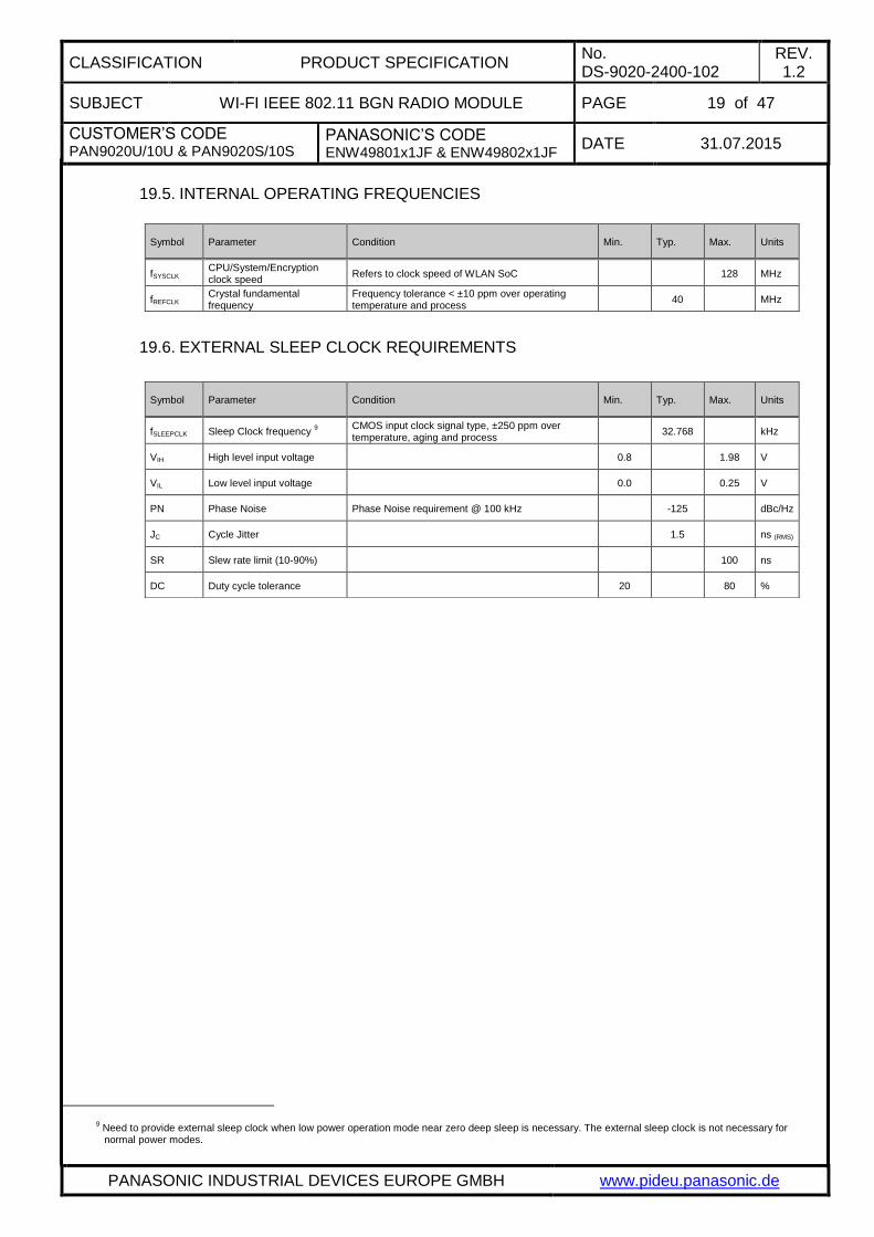
19.5. INTERNAL OPERATING FREQUENCIES
19.6. EXTERNAL SLEEP CLOCK REQUIREMENTS
9 Need to provide external sleep clock when low power operation mode near zero deep sleep is necessary. The external sleep clock is not necessary for normal power modes.
Symbol Parameter Condition Min. Typ. Max. Units
fSYSCLK CPU/System/Encryption clock speed
Refers to clock speed of WLAN SoC 128 MHz
fREFCLK Crystal fundamental frequency
Frequency tolerance < ±10 ppm over operating temperature and process
40 MHz
Symbol Parameter Condition Min. Typ. Max. Units
fSLEEPCLK Sleep Clock frequency 9
CMOS input clock signal type, ±250 ppm over temperature, aging and process
32.768 kHz
VIH High level input voltage 0.8 1.98 V
VIL Low level input voltage 0.0 0.25 V
PN Phase Noise Phase Noise requirement @ 100 kHz -125 dBc/Hz
JC Cycle Jitter 1.5 ns (RMS)
SR Slew rate limit (10-90%) 100 ns
DC Duty cycle tolerance 20 80 %

CLASSIFICATION PRODUCT SPECIFICATION No. DS-9020-2400-102
REV. 1.2
SUBJECT WI-FI IEEE 802.11 BGN RADIO MODULE PAGE 20 of 47
CUSTOMER’S CODE PAN9020U/10U & PAN9020S/10S
PANASONIC’S CODE ENW49801x1JF & ENW49802x1JF
DATE 31.07.2015
PANASONIC INDUSTRIAL DEVICES EUROPE GMBH www.pideu.panasonic.de
19.7. COEXISTENCE INTERFACE SPECIFICATION
The Coexistence Interface pins are powered from the VIO voltage supply internally connected to VDD = 3.3V. See Chapter 19.3 Digital Pin Characteristics for DC specification.
19.7.1. Marvell® 3/4-Wire Timing Data
Symbol Parameter Min. Typ. Max. Units
T1 Priority[0] info is valid in BT_STATE on and after T1 from BT_REQ rise. 0 1 100 µs
T2 TxRx Info is valid in BT_STATE on and after T2. The BT_STATE must hold until there is any change of direction in the next slots.
2 19 100 µs
T3 Time from TxRx Info valid to BCA grant decision (T3 = T7 – T4 – T2 – T8 – T1). 2 40 594 µs
T4
BT_GRANTn needs to be valid T4 time before the upcoming slot. BT_GRANTn indicates Tx grant, and may also indicate Rx grant. Once a slot is granted, the subsequent slots are also granted unless there is a change in direction from Rx to Tx. Rx to Tx change always re-arbitrates.
2 80 594 µs
T5
TxRx Info for the next slot is valid on and after T5 to the start of the next slot. If direction remains the same for the next slot, then BT_STATE must not change during the current slot. If the direction changes for the next slot, the BT_STATE must change only after the last bit of Bluetooth data is transferred; otherwise the transfer may be disrupted.
5 40 600 µs
T6 The BT_REQ signal de-asserts T6 time after last bit of Bluetooth data is transferred. 0 15 25 µs
T7 Time from BT_REQ rise to first Bluetooth slot boundary. Bluetooth slot boundary is marked by first bit of Bluetooth data.
8 150 600 µs
T8
Optional
Priority[1] information is valid in BT_STAT on and after T8. This time parameter only exists if BCA is configured for 2-bit priority on same BT_STATE pin. Otherwise, the start of T2 would come after T1.
2 10 100 µs
Ttx Slot time (fixed fpr Bluetooth) 625 µs
Trx Slot time (fixed fpr Bluetooth) 625 µs

CLASSIFICATION PRODUCT SPECIFICATION No. DS-9020-2400-102
REV. 1.2
SUBJECT WI-FI IEEE 802.11 BGN RADIO MODULE PAGE 21 of 47
CUSTOMER’S CODE PAN9020U/10U & PAN9020S/10S
PANASONIC’S CODE ENW49801x1JF & ENW49802x1JF
DATE 31.07.2015
PANASONIC INDUSTRIAL DEVICES EUROPE GMBH www.pideu.panasonic.de
19.7.2. WL_ACTIVE 2/3/4-Wire Timing Data
Symbol Parameter Min. Typ. Max. Units
T1
If WLAN can be stopped, WL_ACTIVE will de-asser prior to Bluetooth slot start (T1 < T2)
If the Bluetooth device samples WL_ACTIVE before starting priority transfer, WL_ACTIVE needs to de-assert earlier than the sampling time.
0 499 µs
T2 Time from BT_PRIORITY rise to start of Bluetooth activity. 20 50 499 µs
T3 Time from end of Bluetooth activity to BT_PRIORITY fall. 0 0 499 µs
T4 Slot time (fixed fpr Bluetooth) 625 µs

CLASSIFICATION PRODUCT SPECIFICATION No. DS-9020-2400-102
REV. 1.2
SUBJECT WI-FI IEEE 802.11 BGN RADIO MODULE PAGE 22 of 47
CUSTOMER’S CODE PAN9020U/10U & PAN9020S/10S
PANASONIC’S CODE ENW49801x1JF & ENW49802x1JF
DATE 31.07.2015
PANASONIC INDUSTRIAL DEVICES EUROPE GMBH www.pideu.panasonic.de
19.8. HOST INTERFACE SPECIFICATION
19.8.1. USB 2.0 Interface (PAN9020U / PAN9010U)
The USB 2.0 Host Interface pins are powered internally from the VDD = 3.3V. It supports the high / full speed operation (480 / 12 Mbps) depending on the USB bus termination. The default mode is high speed operation.
19.8.1.1. Common Electrical Characteristics
Symbol Parameter Condition Min. Typ. Max. Units
Input Levels for Low / Full Speed
VIH Input high voltage (driven) 2.0 V
VIHZ Input high voltage (floating) 2.7 3.6 V
VIL Input low voltage 0.8 V
VDI Differential input sensitivity 0.2 V
VCM Differential common mode range 0.8 2.5 V
Input Levels for High Speed
VHSSQ High-speed squelch detection threshold (differential signal amplitude)
100 150 mV
VHSDSC High-speed disconnect detection threshold (differential signal amplitude)
525 625 mV
--- High-speed differential input signaling levels
Specified by eye pattern templates; see Section 7.1.7.2 in the USB 2.0 specification
VHSCM High-speed data signaling common mode voltage range
-50 500 mV
Output Levels for Low / Full Speed
VOL Output low voltage 0.0 0.3 V
VOH Output high voltage (driven) 2.8 3.6 V
VOSE1 Output SE1 voltage 0.8 V
VCRS Output signal crossover voltage 1.3 2.0 V
Outpu Levels for High Speed
VHSOI High-speed idle level -10 10 mV
VHSOH High-speed data signaling high 360 440 mV
VHSOL High-speed data signaling low -10 10 mV
VCHIRPJ Chirp J level (differential voltage) 700 1100 mV
VCHIRPK Chirp K level (differential voltage) -900 -500 mV

CLASSIFICATION PRODUCT SPECIFICATION No. DS-9020-2400-102
REV. 1.2
SUBJECT WI-FI IEEE 802.11 BGN RADIO MODULE PAGE 23 of 47
CUSTOMER’S CODE PAN9020U/10U & PAN9020S/10S
PANASONIC’S CODE ENW49801x1JF & ENW49802x1JF
DATE 31.07.2015
PANASONIC INDUSTRIAL DEVICES EUROPE GMBH www.pideu.panasonic.de
17.8.1.1 Common Electrical Characteristics (continued)
19.8.1.2. High Speed Source Electrical Characteristics
Symbol Parameter Condition Min. Typ. Max. Units
Decoupling Capacitance
CRPB Upstream facing port bypass capacitance
1 10 µF
Input Capacitance for Low / Full Speed
CINUB Upstream facing port capacitance (without cable)
100 pF
CEDGE Transceiver edge rate control capacitance
75 pF
Input Impedance for High Speed
--- TDR specification for high-speed termination
Differential impedance 80 100
Terminations
RPUI Bus pull-up resistor on upstream port (idles bus)
0.900 1.575 k
RPUA Bus pull-up resistor on upstream port (receiving)
1.425 3.090 k
ZINP Input impedance exclusive of pull-up / pull-down (for low / full speed)
300 k
VTERM Termination voltage for upstream facing port pull-up resistor (RPU)
3.0 3.6 V
Terminations in High Speed
VHSTERM Termination voltage in high speed -10 10 mV
Symbol Parameter Condition Min. Typ. Max. Units
Driver Characteristics
THSR Rise Time (10% - 90%) 500 ps
THSF Fall Time (10% - 90%) 500 ps
--- Driver waveform requirements Specified by eye pattern templates; see Section 7.1.2 in the USB 2.0 specification
ZHSDRV Driver output resistance (which also serves as high speed termination)
40.5 49.5
Clock Timings
THSDRAT High speed data rate 479.76 480.24 Mbps
THSFRAM Microframe interval 124.9375 125.0625 µs
THSRFI Consecutive microframe interval difference
4 high-
speed bit times
High Speed Data Timings
--- Data source jitter Specified by eye pattern templates; see Section 7.1.2.2 in the USB 2.0 specification
--- Receiver jitter tolerance Specified by eye pattern templates; see Section 7.1.2.2 in the USB 2.0 specification

CLASSIFICATION PRODUCT SPECIFICATION No. DS-9020-2400-102
REV. 1.2
SUBJECT WI-FI IEEE 802.11 BGN RADIO MODULE PAGE 24 of 47
CUSTOMER’S CODE PAN9020U/10U & PAN9020S/10S
PANASONIC’S CODE ENW49801x1JF & ENW49802x1JF
DATE 31.07.2015
PANASONIC INDUSTRIAL DEVICES EUROPE GMBH www.pideu.panasonic.de
19.8.1.3. Full Speed Source Electrical Characteristics
19.8.1.4. Device Event Timings
Symbol Parameter Condition Min. Typ. Max. Units
Driver Characteristics
TFR Rise Time 4 20 ns
TFF Fall Time 4 20 ns
TFRFM Differential rise and fall time matching TFR / TFF 90 111.11 %
Clock Timings
TFDRATHS Full speed data rate Average bit rate 11.994 12.006 Mbps
TFDRATE Frame interval 0.9995 1.0005 µs
THSRFI Consecutive frame interval difference No clock adjustment 42 ms
Full Speed Data Timings
TDJ1 Source Jitter total to next transition (including frequency tolerance)
-3.5 3.5 ns
TDJ2 Source Jitter total to paired transitions (including frequency tolerance)
-4 4 ns
TFDEOP Source Jitter for differential transition to SE0 transition
-2 5 ns
TJR1 Receiver Jitter to next transition -18.5 18.5 ns
TJR2 Receiver Jitter to paired transition -9 9 ns
TFEOPT Source SE0 interval of EOP 160 175 ns
TFEOPR Receiver SE0 interval of EOP 82 ns
TFST Width of SE0 interval during differential transition
14 ns
Symbol Parameter Condition Min. Typ. Max. Units
TSIGATT Time from internal power good device pulling D+/D- beyond VIHZ (min) (signaling attach)
100 ms
TATTDB Debounce interval provided by USB system software after attach
100 ms
T2SUSP Maximum time a device can draw power > suspend power when bus is continuously in idle state
10 ms
TSUSAVGI Maximum duration of suspend averaging interval
1 s
TWTRSM Period of idle bus before device can initiate resum
Device must be remote-wake-up enabled
5 ms
TDRSMUP Duration of driving resume upstream 1 15 ms
TRSMCY Resume recovery time Provided by USB system software 10 ms
TRSTRCYI Reset recovery time 10 ms
TIPD Inter-packet delay (for low/full speed) 2 bit times
TRSPIPD1 Inter-packet delay for device response with detachable cable for low/full speed
6.5 bit times
TRSPIPD2 Inter-packet delay for device response with captive cable for low/full speed
7.5 bit times
TDSETADDR SetAddress() completion time 50 ms

CLASSIFICATION PRODUCT SPECIFICATION No. DS-9020-2400-102
REV. 1.2
SUBJECT WI-FI IEEE 802.11 BGN RADIO MODULE PAGE 25 of 47
CUSTOMER’S CODE PAN9020U/10U & PAN9020S/10S
PANASONIC’S CODE ENW49801x1JF & ENW49802x1JF
DATE 31.07.2015
PANASONIC INDUSTRIAL DEVICES EUROPE GMBH www.pideu.panasonic.de
17.8.1.4 Device Event Timings (continued)
Symbol Parameter Condition Min. Typ. Max. Units
TDRQCMPLTND Time to complete standard request with no data
50 ms
TDRETDATA1 Time to deliver first and subsequent (except last) data for standard request
500 ms
TDRETDATAN Time to deliver last data for standard request
50 ms
THSRSPIPD2 Inter-packet delay for device response with captive cable (high speed)
192 bit times + 52ns
ms
Reset Handshake Protocol
FFILTSE0
Time for which a suspended high speed capable device must see a continuous SE0 before beginning the high speed detection handshake
2.5 µs
TWTRSTFS
Time for which high speed capable device operating in non-suspended full speed must wait after start of SE0 before beginning the high speed detection handshake
2.5 3000 µs
TWTREV
Time for which high speed capable device operating in high speed must wait after start of SE0 before reverting to full speed
3.0 3.125 ms
TWTRSTHS
Time for which a device must wait after reverting to full speed before sampling the bus state for SE0 and beginning the high speed detection handshake
100 875 µs
TUCH Minimum duration of a Chirp K from a high speed capable device within the reset protocol
1.0 ms
TUCHEND
Time after start of SE0 by which a high speed capable device is required to have completed its Chirp K within the reset
protocol
7.01 ms
TWTHS
Time after end of upstream chirp at which device enters the high speed default state if downstream chirp is detected
500 µs
TWTFS Time after end of upstream chirp at which device reverts to full speed default state if no downstream chirp is detected
1.0 2.5 ms

CLASSIFICATION PRODUCT SPECIFICATION No. DS-9020-2400-102
REV. 1.2
SUBJECT WI-FI IEEE 802.11 BGN RADIO MODULE PAGE 26 of 47
CUSTOMER’S CODE PAN9020U/10U & PAN9020S/10S
PANASONIC’S CODE ENW49801x1JF & ENW49802x1JF
DATE 31.07.2015
PANASONIC INDUSTRIAL DEVICES EUROPE GMBH www.pideu.panasonic.de
19.8.2. SDIO Interface (PAN9020S / PAN9010S)
The SDIO Host Interface pins are powered from the VIO voltage supply internally connected to VDD = 3.3V. See Chapter 19.3 Digital Pin Characteristics for DC specification. The SDIO electrical specifications are identical for the 1-bit SDIO and 4-bit SDIO modes.
19.8.2.1. SDIO Timing Data
19.8.2.2. SDIO Protocol Timing – Normal Mode
Symbol Parameter Condition Min. Typ. Max. Units
fPP Clock frequency
Normal 0 25 MHz
High Speed 0 50 MHz
TWL Clock low time
Normal 10 ns
High Speed 7 ns
TWH Clock high time
Normal 10 ns
High Speed 7 ns
TISU Input setup time
Normal 5 ns
High Speed 6 ns
TIH Input hold time
Normal 5 ns
High Speed 2 ns
TODLY Output delay time 7.33 ns
TOH Output hold time High Speed 2.5 ns
CLASSIFICATION PRODUCT SPECIFICATION No. DS-9020-2400-102
REV. 1.2
SUBJECT WI-FI IEEE 802.11 BGN RADIO MODULE PAGE 27 of 47
CUSTOMER’S CODE PAN9020U/10U & PAN9020S/10S
PANASONIC’S CODE ENW49801x1JF & ENW49802x1JF
DATE 31.07.2015
PANASONIC INDUSTRIAL DEVICES EUROPE GMBH www.pideu.panasonic.de
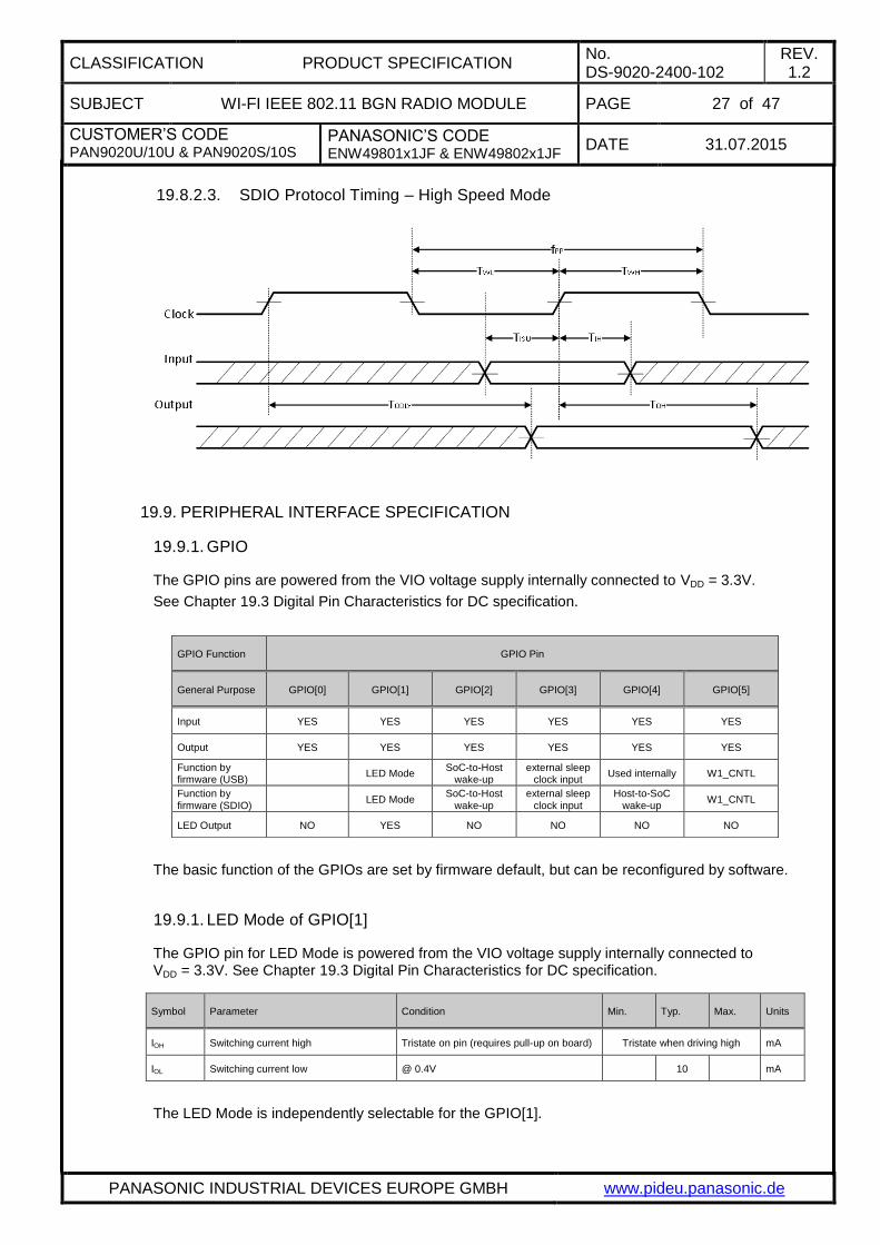
19.8.2.3. SDIO Protocol Timing – High Speed Mode
19.9. PERIPHERAL INTERFACE SPECIFICATION
19.9.1. GPIO
The GPIO pins are powered from the VIO voltage supply internally connected to VDD = 3.3V.
See Chapter 19.3 Digital Pin Characteristics for DC specification.
The basic function of the GPIOs are set by firmware default, but can be reconfigured by software.
19.9.1. LED Mode of GPIO[1]
The GPIO pin for LED Mode is powered from the VIO voltage supply internally connected to VDD = 3.3V. See Chapter 19.3 Digital Pin Characteristics for DC specification.
The LED Mode is independently selectable for the GPIO[1].
GPIO Function GPIO Pin
General Purpose GPIO[0] GPIO[1] GPIO[2] GPIO[3] GPIO[4] GPIO[5]
Input YES YES YES YES YES YES
Output YES YES YES YES YES YES
Function by firmware (USB)
LED Mode SoC-to-Host
wake-up external sleep
clock input Used internally W1_CNTL
Function by firmware (SDIO)
LED Mode SoC-to-Host
wake-up external sleep
clock input Host-to-SoC
wake-up W1_CNTL
LED Output NO YES NO NO NO NO
Symbol Parameter Condition Min. Typ. Max. Units
IOH Switching current high Tristate on pin (requires pull-up on board) Tristate when driving high mA
IOL Switching current low @ 0.4V 10 mA

CLASSIFICATION PRODUCT SPECIFICATION No. DS-9020-2400-102
REV. 1.2
SUBJECT WI-FI IEEE 802.11 BGN RADIO MODULE PAGE 28 of 47
CUSTOMER’S CODE PAN9020U/10U & PAN9020S/10S
PANASONIC’S CODE ENW49801x1JF & ENW49802x1JF
DATE 31.07.2015
PANASONIC INDUSTRIAL DEVICES EUROPE GMBH www.pideu.panasonic.de
20. RF ELECTRICAL CHARACTERISTICS
20.1. WLAN RADIO SPECIFICATION
10
The supported channels are defined by setting of country code
Parameter Operation mode Specification
Standard Conformance
IEEE 802.11 / IEEE 802.11b
IEEE 802.11g
IEEE 802.11n
Modulation
IEEE 802.11b DSSS / CCK
IEEE 802.11g OFDM
IEEE 802.11n OFDM @ MCS0~7 and MCS32 (duplicate 6 Mbps)
Physical layer data rates
IEEE 802.11 1, 2 Mbps @ DSSS
IEEE 802.11b 5.5, 11 Mbps @ DSSS / CCK
Supported data rates
IEEE 802.11g 6, 9, 12, 18, 24, 36, 48, 54 Mbps
IEEE 802.11n MCS0~7
HT20
LGI 6.5, 13, 19.5, 26, 39, 52, 58.5, 65 Mbps
SGI 7.2, 14.4, 21.7, 28.9, 43.3, 57.8, 65, 72.2 Mbps
HT40
LGI 13.5, 27, 40.5, 54, 81, 108, 121.5, 135 Mbps
SGI 15, 30, 45, 60, 90, 120, 135, 150 Mbps
Supported bandwidth IEEE 802.11n 20, 40 MHz (BW)
Supported channel mode operation IEEE 802.11n
20 MHz BW / channel, 40 MHz BW / channel,
upper / lower 20 MHz BW @ 40 MHz channel,
20 MHz duplicate legacy BW @ 40 MHz channel
Supported Guard Interval IEEE 802.11n 400 ns (SGI), 800 ns (LGI)
Supported channel 2.4GHz 10
IEEE 802.11g
North America 1, 2, 3, 4, 5, 6, 7, 8, 9, 10, 11
Europe 1, 2, 3, 4, 5, 6, 7, 8, 9, 10, 11, 12, 13
Spain 10, 11
France 10, 11, 12, 13
Japan MMK 1, 2, 3, 4, 5, 6, 7, 8, 9, 10, 11, 12, 13
IEEE 802.11n
North America
1-5, 2-6, 3-7, 4-8, 5-9, 6-10, 7-11
Europe
Spain
France
Japan MMK -

CLASSIFICATION PRODUCT SPECIFICATION No. DS-9020-2400-102
REV. 1.2
SUBJECT WI-FI IEEE 802.11 BGN RADIO MODULE PAGE 29 of 47
CUSTOMER’S CODE PAN9020U/10U & PAN9020S/10S
PANASONIC’S CODE ENW49801x1JF & ENW49802x1JF
DATE 31.07.2015
PANASONIC INDUSTRIAL DEVICES EUROPE GMBH www.pideu.panasonic.de
20.2. WLAN RF CHARACTERISTICS
20.2.1. RF Characteristics for IEEE 802.11b
Assume VDD = 3.3V, Tamb = 25°C if nothing else stated 50 Ohm terminal load connected to the RF connector
Parameter Condition Min. Typ. Max. Units
RF frequency range 2400 2483.5 MHz
Carrier frequency tolerance -25 +25 ppm
Transmit output power +16 +18 +20 dBm
Spectrum mask
fC ± 11 MHz -30 dBr
fC ± 22 MHz -50
Power-on / Power-down ramp 2 µs
RF Carrier suppression -15 dB
Error Vector Magnitude (EVM) Peak 35 %
Minimum Receive Sensitivity
1 Mbps (DSSS) FER ≤ 8% -98 -86 dBm
2 Mbps (DSSS) FER ≤ 8% -95 -83 dBm
5.5 Mbps (CCK) FER ≤ 8% -91 -79 dBm
11 Mbps (CCK) FER ≤ 8% -88 -76 dBm
Maximum Input Level FER ≤ 8% -10 dBm
Adjacent Channel Rejection FER ≤ 8% 35 dB

CLASSIFICATION PRODUCT SPECIFICATION No. DS-9020-2400-102
REV. 1.2
SUBJECT WI-FI IEEE 802.11 BGN RADIO MODULE PAGE 30 of 47
CUSTOMER’S CODE PAN9020U/10U & PAN9020S/10S
PANASONIC’S CODE ENW49801x1JF & ENW49802x1JF
DATE 31.07.2015
PANASONIC INDUSTRIAL DEVICES EUROPE GMBH www.pideu.panasonic.de
20.2.2. RF Characteristics for IEEE 802.11g
Assume VDD = 3.3V, Tamb = 25°C if nothing else stated 50 Ohm terminal load connected to the RF connector
Parameter Condition Min. Typ. Max. Units
RF frequency range 2400 2483.5 MHz
Carrier frequency tolerance -25 +25 ppm
Transmit output power
6 Mbps ~ 36 Mbps +14 +16 +18 dBm
48 Mbps ~ 54 Mbps +13 +15 +17 dBm
Spectrum mask
fC ± 11 MHz -20 dBr
fC ± 20 MHz -28 dBr
fC ± 30 MHz -40 dBr
Transmitter center frequency leakage -15 dB
Transmitter Spectral Flatness -2 +2 dB
Constellation Error (EVM)
BPSK, CR 1/2 (6 Mbps) -5 dB
BPSK, CR 3/4 (9 Mbps) -8 dB
QPSK, CR 1/2 (12 Mbps) -10 dB
QPSK, CR 3/4 (18 Mbps) -13 dB
16-QAM, CR 1/2 (24 Mbps) -16 dB
16-QAM, CR 3/4 (36 Mbps) -19 dB
64-QAM, CR 2/3 (48 Mbps) -22 dB
64-QAM, CR 3/4 (54 Mbps) -25 dB
Minimum Receive Sensitivity
BPSK, CR 1/2 (6 Mbps) PER ≤ 10% -93 -82 dBm
BPSK, CR 3/4 (9 Mbps) PER ≤ 10% -92 -81 dBm
QPSK, CR 1/2 (12 Mbps) PER ≤ 10% -90 -79 dBm
QPSK, CR 3/4 (18 Mbps) PER ≤ 10% -88 -77 dBm
16-QAM, CR 1/2 (24 Mbps) PER ≤ 10% -85 -74 dBm
16-QAM, CR 3/4 (36 Mbps) PER ≤ 10% -81 -70 dBm
64-QAM, CR 2/3 (48 Mbps) PER ≤ 10% -77 -66 dBm
64-QAM, CR 3/4 (54 Mbps) PER ≤ 10% -76 -65 dBm
Maximum Input Level PER ≤ 10% -20 dBm
Adjacent channel rejection
BPSK, CR 1/2 (6 Mbps) PER ≤ 10% 16 dB
64-QAM, CR 3/4 (54 Mbps) PER ≤ 10% -1 dB

CLASSIFICATION PRODUCT SPECIFICATION No. DS-9020-2400-102
REV. 1.2
SUBJECT WI-FI IEEE 802.11 BGN RADIO MODULE PAGE 31 of 47
CUSTOMER’S CODE PAN9020U/10U & PAN9020S/10S
PANASONIC’S CODE ENW49801x1JF & ENW49802x1JF
DATE 31.07.2015
PANASONIC INDUSTRIAL DEVICES EUROPE GMBH www.pideu.panasonic.de
20.2.3. RF Characteristics for IEEE 802.11n (BW 20 MHz)
Assume VDD = 3.3V, Tamb = 25°C if nothing else stated 50 Ohm terminal load connected to the RF connector
11
The Minimum Sensitivity levels apply only to non-STBC modes, MCS 0~7, 800 ns LGI and BCC.
12 The Adjacent Channel Rejection levels apply only to non-STBC modes, MCS 0~7, 800 ns LGI and BCC.
Parameter Condition Min. Typ. Max. Units
RF frequency range 2400 2483.5 MHz
Carrier frequency tolerance -25 +25 ppm
Transmit output power
MCS0 ~ MCS2 13 15 17 dBm
MCS3 ~ MCS4 12 14 16 dBm
MCS5 ~ MCS7 11 13 15 dBm
Spectrum mask
fC ± 11 MHz -20 dBr
fC ± 20 MHz -28 dBr
fC ± 30 MHz -45 dBr
Transmitter center frequency leakage -15 dB
Transmitter Spectral Flatness -2 +2 dB
Constellation Error (EVM)
BPSK, CR 1/2 (MCS0) -5 dB
QPSK, CR 1/2 (MCS1) -10 dB
QPSK, CR 3/4 (MCS2) -13 dB
16-QAM, CR 1/2 (MCS3) -16 dB
16-QAM, CR 3/4 (MCS4) -19 dB
64-QAM, CR 2/3 (MCS5) -22 dB
64-QAM, CR 3/4 (MCS6) -25 dB
64-QAM, CR 5/6 (MCS7) -27 dB
Minimum Receive Sensitivity 11
6.5 Mbps (MCS0) PER ≤ 10% -92 -82 dBm
13 Mbps (MCS1) PER ≤ 10% -89 -79 dBm
19.5 Mbps (MCS2) PER ≤ 10% -87 -77 dBm
26 Mbps (MCS3) PER ≤ 10% -84 -74 dBm
39 Mbps (MCS4) PER ≤ 10% -80 -70 dBm
52 Mbps (MCS5) PER ≤ 10% -76 -66 dBm
58.5 Mbps (MCS6) PER ≤ 10% -75 -65 dBm
65 Mbps (MCS7) PER ≤ 10% -74 -64 dBm
Maximum Input Level PER ≤ 10% -20 dBm
Adjacent channel rejection 12
65 Mbps (MCS7) PER ≤ 10% -2 dB

CLASSIFICATION PRODUCT SPECIFICATION No. DS-9020-2400-102
REV. 1.2
SUBJECT WI-FI IEEE 802.11 BGN RADIO MODULE PAGE 32 of 47
CUSTOMER’S CODE PAN9020U/10U & PAN9020S/10S
PANASONIC’S CODE ENW49801x1JF & ENW49802x1JF
DATE 31.07.2015
PANASONIC INDUSTRIAL DEVICES EUROPE GMBH www.pideu.panasonic.de
20.2.4. RF Characteristics for IEEE 802.11n (BW 40 MHz)
Assume VDD = 3.3V, Tamb = 25°C if nothing else stated 50 Ohm terminal load connected to the RF connector
Parameter Condition Min. Typ. Max. Units
RF frequency range 2400 2483.5 MHz
Carrier frequency tolerance -25 +25 ppm
Transmit output power
MCS0 ~ MCS2 11 13 15 dBm
MCS3 ~ MCS4 10 12 14 dBm
MCS5 ~ MCS7 9 11 13 dBm
Spectrum mask
fC ± 21 MHz -20 dBr
fC ± 40 MHz -28 dBr
fC ± 60 MHz -45 dBr
Transmitter center frequency leakage -15 dB
Transmitter Spectral Flatness -2 +2 dB
Constellation Error (EVM)
BPSK, CR 1/2 (MCS0) -5 dB
QPSK, CR 1/2 (MCS1) -10 dB
QPSK, CR 3/4 (MCS2) -13 dB
16-QAM, CR 1/2 (MCS3) -16 dB
16-QAM, CR 3/4 (MCS4) -19 dB
64-QAM, CR 2/3 (MCS5) -22 dB
64-QAM, CR 3/4 (MCS6) -25 dB
64-QAM, CR 5/6 (MCS7) -27 dB
Minimum Receive Sensitivity 11
13.5 Mbps (MCS0) PER ≤ 10% -89 -79 dBm
27 Mbps (MCS1) PER ≤ 10% -86 -76 dBm
40.5 Mbps (MCS2) PER ≤ 10% -84 -74 dBm
54 Mbps (MCS3) PER ≤ 10% -81 -71 dBm
81 Mbps (MCS4) PER ≤ 10% -77 -67 dBm
108 Mbps (MCS5) PER ≤ 10% -73 -63 dBm
121.5 Mbps (MCS6) PER ≤ 10% -72 -62 dBm
135 Mbps (MCS7) PER ≤ 10% -71 -61 dBm
Maximum Input Level PER ≤ 10% -20 dBm
Adjacent channel rejection 12
135 Mbps (MCS7) PER ≤ 10% -2 dB

CLASSIFICATION PRODUCT SPECIFICATION No. DS-9020-2400-102
REV. 1.2
SUBJECT WI-FI IEEE 802.11 BGN RADIO MODULE PAGE 33 of 47
CUSTOMER’S CODE PAN9020U/10U & PAN9020S/10S
PANASONIC’S CODE ENW49801x1JF & ENW49802x1JF
DATE 31.07.2015
PANASONIC INDUSTRIAL DEVICES EUROPE GMBH www.pideu.panasonic.de
21. SOLDERING TEMPERATURE-TIME PROFILE (FOR REFLOW SOLDERING)
21.1. FOR LEAD SOLDER
Recommended temp. profile
for reflow soldering
Temp.[°C]
Time [s]
235°C max.
220 5°C
200°C
150 10°C
90 30s
10 1s
30 +20/-10s
21.2. FOR LEADFREE SOLDER
Our used temp. profile
for reflow soldering
Temp.[°C]
Time [s]
230°C -250°C max.
220°C
150°C – 190°C
90 30s
30 +20/-10s
Reflow permissible cycle: 2 Opposite side reflow is prohibited due to module weight.

CLASSIFICATION PRODUCT SPECIFICATION No. DS-9020-2400-102
REV. 1.2
SUBJECT WI-FI IEEE 802.11 BGN RADIO MODULE PAGE 34 of 47
CUSTOMER’S CODE PAN9020U/10U & PAN9020S/10S
PANASONIC’S CODE ENW49801x1JF & ENW49802x1JF
DATE 31.07.2015
PANASONIC INDUSTRIAL DEVICES EUROPE GMBH www.pideu.panasonic.de
22. PAN9020 / PAN9010 MODULE DIMENSION
No. Item Dimension Tolerance Remark
1 Width 13.50 0.30
2 Length 22.75 0.30
3 Height 2.42 0.20 with case

CLASSIFICATION PRODUCT SPECIFICATION No. DS-9020-2400-102
REV. 1.2
SUBJECT WI-FI IEEE 802.11 BGN RADIO MODULE PAGE 35 of 47
CUSTOMER’S CODE PAN9020U/10U & PAN9020S/10S
PANASONIC’S CODE ENW49801x1JF & ENW49802x1JF
DATE 31.07.2015
PANASONIC INDUSTRIAL DEVICES EUROPE GMBH www.pideu.panasonic.de
23. PAN9020 / PAN9010 FOOTPRINT OF THE MODULE
All dimensions are in millimeters.
The outer dimensions have a tolerance of 0.3mm.
Top view, Application PCB

CLASSIFICATION PRODUCT SPECIFICATION No. DS-9020-2400-102
REV. 1.2
SUBJECT WI-FI IEEE 802.11 BGN RADIO MODULE PAGE 36 of 47
CUSTOMER’S CODE PAN9020U/10U & PAN9020S/10S
PANASONIC’S CODE ENW49801x1JF & ENW49802x1JF
DATE 31.07.2015
PANASONIC INDUSTRIAL DEVICES EUROPE GMBH www.pideu.panasonic.de
24. CASE MARKING (EXAMPLE FOR PAN9020U)
24.1. MARKING DESCRIPTION
24.2. DETAILED MARKING DEFINITION
(1) Pin1 marking
(2) 2D code (Serial number)
(3) Marking:
PAN90x0y (Model Name), HW/SW (Hardware/Software version)
- y = U USB, y = S SDIO
- x = 2 ceramic chip-antenna (PAN9020), x = 1 50 Ohm bottom pad (PAN9010)
ES (Engineering Sample marking)
ENW4980yx1JF (Part Number, refer to chapter 30 Ordering Information)
- y = 1 USB, y = 2 SDIO
- x = A ceramic chip-antenna (PAN9020), x = C 50 Ohm bottom pad (PAN9010)
Lot code (YearYear, WeekWeek, Day, LotLot)
Serial Number (8 digits)
WLAN MAC address (12 digits)
IC Canada (refer to chaper 32 Regulatory Information)
- y = U USB, y = S SDIO
Note: For available Versions, refer to [1] PAN9020U and PAN9020S Reference-Guide.
and chapter 30 Ordering Information.
No. Remark
1 Marking for Pin 1 (Circle 0,15 mm)
2 2D-Code, for internal usage only and can be change without any notice
3 Marking definition see below
P A N 9 0 x 0 y H W / S W E S
E N W 4 9 8 0 y x 1 J F
Y Y W W D L L
S N S N S N S N
M A C M A C M A C M A C
I C : 2 1 6 Q - 9 0 2 0 y

CLASSIFICATION PRODUCT SPECIFICATION No. DS-9020-2400-102
REV. 1.2
SUBJECT WI-FI IEEE 802.11 BGN RADIO MODULE PAGE 37 of 47
CUSTOMER’S CODE PAN9020U/10U & PAN9020S/10S
PANASONIC’S CODE ENW49801x1JF & ENW49802x1JF
DATE 31.07.2015
PANASONIC INDUSTRIAL DEVICES EUROPE GMBH www.pideu.panasonic.de
25. MECHANICAL REQUIREMENTS
26. DEVELOPMENT OF APPLICATIONS
For development support please refer to [1] PAN9020U and PAN9020S Reference-Guide.
27. RELIABILITY TESTS
The measurement should be done after being exposed to room temperature and humidity for 1 hour.
28. CAUTIONS
Failure to follow the guidelines set forth in this document may result in degrading of the product’s functions and damage to the product.
28.1. DESIGN NOTES
(1) Follow the conditions written in this specification, especially the control signals of this
module.
(2) The supply voltage has to be free of AC ripple voltage (for example from a battery or a
low noise regulator output). For noisy supply voltages, provide a decoupling circuit (for
example a ferrite in series connection and a bypass capacitor to ground of at least 47uF
directly at the module).
(3) This product should not be mechanically stressed when installed.
(4) Keep this product away from heat. Heat is the major cause of decreasing the life of these
products.
(5) Avoid assembly and use of the target equipment in conditions where the products'
temperature may exceed the maximum tolerance.
(6) The supply voltage should not be exceedingly high or reversed. It should not carry noise
and/or spikes.
(7) Keep this product away from other high frequency circuits.
No. Item Limit Condition
1 Solderability More than 75% of the soldering area shall be coated by solder
Reflow soldering with recommendable temperature profile
2 Resistance to soldering heat
It shall be satisfied electrical requirements and not be mechanical damage
See chapter 21.2
No. Item Limit Condition
1 Vibration test Electrical parameter should be in specification
a) Freq.:10~50Hz,Amplitude:1.5mm
a) 20min. / cycle,1hrs. each of XYZ axis
b) Freq.:30~100Hz, 6G
b) 20min. / cycle,1hrs. each of XYZ axis
2 Shock test the same as above Dropped onto hard wood from height of 50cm for 3 times
3 Heat cycle test the same as above -40°C for 30min. and +85°C for 30min.;
each temperature 300 cycles
4 Moisture test the same as above +60°C, 90% RH, 300h
5 Low temp. test the same as above -40°C, 300h
6 High temp. test the same as above +85°C, 300h

CLASSIFICATION PRODUCT SPECIFICATION No. DS-9020-2400-102
REV. 1.2
SUBJECT WI-FI IEEE 802.11 BGN RADIO MODULE PAGE 38 of 47
CUSTOMER’S CODE PAN9020U/10U & PAN9020S/10S
PANASONIC’S CODE ENW49801x1JF & ENW49802x1JF
DATE 31.07.2015
PANASONIC INDUSTRIAL DEVICES EUROPE GMBH www.pideu.panasonic.de
28.2. INSTALLATION NOTES
(1) Reflow soldering is possible twice based on the conditions in chapter 15.
Set up the temperature at the soldering portion of this product according to this reflow
profile.
(2) Carefully position the products so that their heat will not burn into printed circuit boards or
affect the other components that are susceptible to heat.
(3) Carefully locate these products so that their temperatures will not increase due to the
effects of heat generated by neighboring components.
(4) If a vinyl-covered wire comes into contact with the products, then the cover will melt and
generate toxic gas, damaging the insulation. Never allow contact between the cover and
these products to occur.
(5) This product should not be mechanically stressed or vibrated when reflowed.
(6) To repair the board by hand soldering, follow the conditions set forth in this chapter.
(7) Do not wash this product.
(8) Refer to the recommended pattern when designing a board.
(9) Pressing on parts of the metal cover or fastening objects to the metal will cause damage
to the unit.
(10) For more details on LGA (Land Grid Array) soldering processes refer to the application
note.
28.3. USAGE CONDITIONS NOTES
(1) Take measures to protect the unit against static electricity.
If pulses or other transient loads (a large load applied in a short time) are applied to the
products, check and evaluate their operation befor assembly on the final products.
(2) Do not use dropped products.
(3) Do not touch, damage or soil the pins.
(4) Follow the recommended condition ratings about the power supply applied to this
product.
(5) Electrode peeling strength: Do not add pressure of more than 4.9N when soldered on
PCB.
(6) Pressing on parts of the metal cover or fastening objects to the metal cover will cause
damage.
(7) These products are intended for general purpose and standard use in general electronic
equipment, such as home appliances, office equipment, information and communication
equipment.
28.4. STORAGE NOTES
(1) The module should not be stressed mechanically during storage.
(2) Do not store these products in the following conditions or the performance characteristics
of the product, such as RF performance will be adversely affected:
Storage in salty air or in an environment with a high concentration of corrosive gas, such as Cl2, H2S, NH3, SO2, or NOX
Storage in direct sunlight
Storage in an environment where the temperature may be outside the range of 5°C to 35°C range, or where the humidity may be outside the 45 to 85% range.
Storage of the products for more than one year after the date of delivery Storage period: Please check the adhesive strength of the embossed tape and soldering after 6 months of storage.
(3) Keep this product away from water, poisonous gas and corrosive gas.

CLASSIFICATION PRODUCT SPECIFICATION No. DS-9020-2400-102
REV. 1.2
SUBJECT WI-FI IEEE 802.11 BGN RADIO MODULE PAGE 39 of 47
CUSTOMER’S CODE PAN9020U/10U & PAN9020S/10S
PANASONIC’S CODE ENW49801x1JF & ENW49802x1JF
DATE 31.07.2015
PANASONIC INDUSTRIAL DEVICES EUROPE GMBH www.pideu.panasonic.de
(4) This product should not be stressed or shocked when transported.
(5) Follow the specification when stacking packed crates (max. 10).
28.5. SAFETY CAUTIONS
These specifications are intended to preserve the quality assurance of products and individual components.
Before use, check and evaluate the operation when mounted on your products. Abide by these specifications, without deviation when using the products. These products may short-circuit. If electrical shocks, smoke, fire, and/or accidents involving human life are anticipated when a short circuit occurs, then provide the following failsafe functions, as a minimum.
(1) Ensure the safety of the whole system by installing a protection circuit and a protection
device.
(2) Ensure the safety of the whole system by installing a redundant circuit or another system to
prevent a single fault causing an unsafe status.
28.6. OTHER CAUTIONS
(1) This specification sheet is copyrighted. Please do not disclose it to a third party.
(2) Please do not use the products for other purposes than those listed.
(3) Be sure to provide an appropriate fail-safe function on your product to prevent an additional
damage that may be caused by the abnormal function or the failure of the product.
(4) This product has been manufactured without any ozone chemical controlled under the
Montreal Protocol.
(5) These products are not intended for other uses, other than under the special conditions
shown below. Before using these products under such special conditions, check their
performance and reliability under the said special conditions carefully to determine
whether or not they can be used in such a manner.
In liquid, such as water, salt water, oil, alkali, or organic solvent, or in places where liquid may splash.
In direct sunlight, outdoors, or in a dusty environment
In an environment where condensation occurs.
In an environment with a high concentration of harmful gas (e.g. salty air, HCl, Cl2, SO2, H2S, NH3, and NOX)
(6) If an abnormal voltage is applied due to a problem occurring in other components or
circuits, replace these products with new products because they may not be able to
provide normal performance even if their electronic characteristics and appearances
appear satisfactory.
(7) When you have any question or uncertainty, contact Panasonic.

CLASSIFICATION PRODUCT SPECIFICATION No. DS-9020-2400-102
REV. 1.2
SUBJECT WI-FI IEEE 802.11 BGN RADIO MODULE PAGE 40 of 47
CUSTOMER’S CODE PAN9020U/10U & PAN9020S/10S
PANASONIC’S CODE ENW49801x1JF & ENW49802x1JF
DATE 31.07.2015
PANASONIC INDUSTRIAL DEVICES EUROPE GMBH www.pideu.panasonic.de
29. PACKAGING
If the product has mass production status, indicated in chapter 3, we will deliver the module in the package which are described below.
29.1. PAN9020 / PAN9010 TAPE DIMENSION
29.2. PACKING IN TAPE
Empty spaces in component packed area shall be less than two per reel and those spaces shall not be consecutive.
Top cover tape shall not be found on reel holes and shall not stick out from reel.

CLASSIFICATION PRODUCT SPECIFICATION No. DS-9020-2400-102
REV. 1.2
SUBJECT WI-FI IEEE 802.11 BGN RADIO MODULE PAGE 41 of 47
CUSTOMER’S CODE PAN9020U/10U & PAN9020S/10S
PANASONIC’S CODE ENW49801x1JF & ENW49802x1JF
DATE 31.07.2015
PANASONIC INDUSTRIAL DEVICES EUROPE GMBH www.pideu.panasonic.de
29.3. COMPONENT DIRECTION
29.4. REEL DIMENSION

CLASSIFICATION PRODUCT SPECIFICATION No. DS-9020-2400-102
REV. 1.2
SUBJECT WI-FI IEEE 802.11 BGN RADIO MODULE PAGE 42 of 47
CUSTOMER’S CODE PAN9020U/10U & PAN9020S/10S
PANASONIC’S CODE ENW49801x1JF & ENW49802x1JF
DATE 31.07.2015
PANASONIC INDUSTRIAL DEVICES EUROPE GMBH www.pideu.panasonic.de
29.5. LABEL FOR PACKAGE
The picture shows an example from similar product.
(1T) Lot code [YYWWDLL-AAA] Example from above: YY year printed 08 WW normal calendar week printed 01 D day printed 5 (Friday) L line identifier, if more as one printed 1 L lot identifier per day printed 1 AAA number of the reel (example 001, 002,…, 999) printed 001
(1P) Customer Order Code, if any, otherwise company name will be printed
(2P) Panasonic Order Code: ENW49801x1J
(9D) Date code as [YYWW]
(Q) Quantity [XXXX], variable max. 500
(HW/SW) Hardware /Software Release Hardware 01 Indicates the HW revision. Software 01 Indicates the SW revision.
29.6. TOTAL PACKAGE
barcode
label
moisture-sensitive print
(already exist on barrier bag)barcode
label
desiccant 1) 2)
moisture indicator
barrier bag
sealed
inner carton box
size 340 x 340 x 41 mm³
1) quantity of desiccant according
to calculation
2) optional: desiccant placed into
the corner of the barrier bag

CLASSIFICATION PRODUCT SPECIFICATION No. DS-9020-2400-102
REV. 1.2
SUBJECT WI-FI IEEE 802.11 BGN RADIO MODULE PAGE 43 of 47
CUSTOMER’S CODE PAN9020U/10U & PAN9020S/10S
PANASONIC’S CODE ENW49801x1JF & ENW49802x1JF
DATE 31.07.2015
PANASONIC INDUSTRIAL DEVICES EUROPE GMBH www.pideu.panasonic.de
30. ORDERING INFORMATION
Notes:
(1) Abbreviation for Minimum Order Quantity (MOQ). The standard MOQ for mass production is 500 pieces, fewer only on customer demand. Samples for evaluation can be delivered at any quantity via the distribution channels.
30.1. INFORMATION REGARDING SOFTWARE VERSIONS
ENW49801/02A1JF / ENW49801/02C1JF:
The modules will be delivered without any WLAN Firmware but including calibration data.
The WLAN SoC Firmware and HOST Driver-Firmware Interface software modules taking place on the customers HOST processor and need to be programmed on their own production process.
For details refer to the reference guide.
31. ROHS DECLARATION
Declaration of environmental compatibility for supplied products:
Hereby we declare to our best present knowledge based on declaration of our suppliers that this product does not contain the following substances which are banned by Directive 2002/95/EC (RoHS) or contains a maximum concentration of 0.1% by weight in homogeneous materials for
Lead and lead compounds
Mercury and mercury compounds
Chromium (VI)
PBB (polybrominated biphenyl) category
PBDE (polybrominated biphenyl ether) category
And a maximum concentration of 0.01% by weight in homogeneous materials for
Cadmium and cadmium compounds
Ordering part number Description MOQ (1)
ENW49801A1JF
PAN9020U
WLAN IEEE 802.11 b/g/n 2.4GHz Radio Module
with USB2.0 HOST Interface, ceramic chip-antenna
500
ENW49802A1JF
PAN9020S
WLAN IEEE 802.11 b/g/n 2.4GHz Radio Module
with SDIO HOST Interface, ceramic chip-antenna
500
ENW49801C1JF
PAN9010U
WLAN IEEE 802.11 b/g/n 2.4GHz Radio Module
with USB2.0 HOST Interface, with 50 bottom pad
500
ENW49802C1JF
PAN9010S
WLAN IEEE 802.11 b/g/n 2.4GHz Radio Module
with SDIO HOST Interface, with 50 bottom pad
500
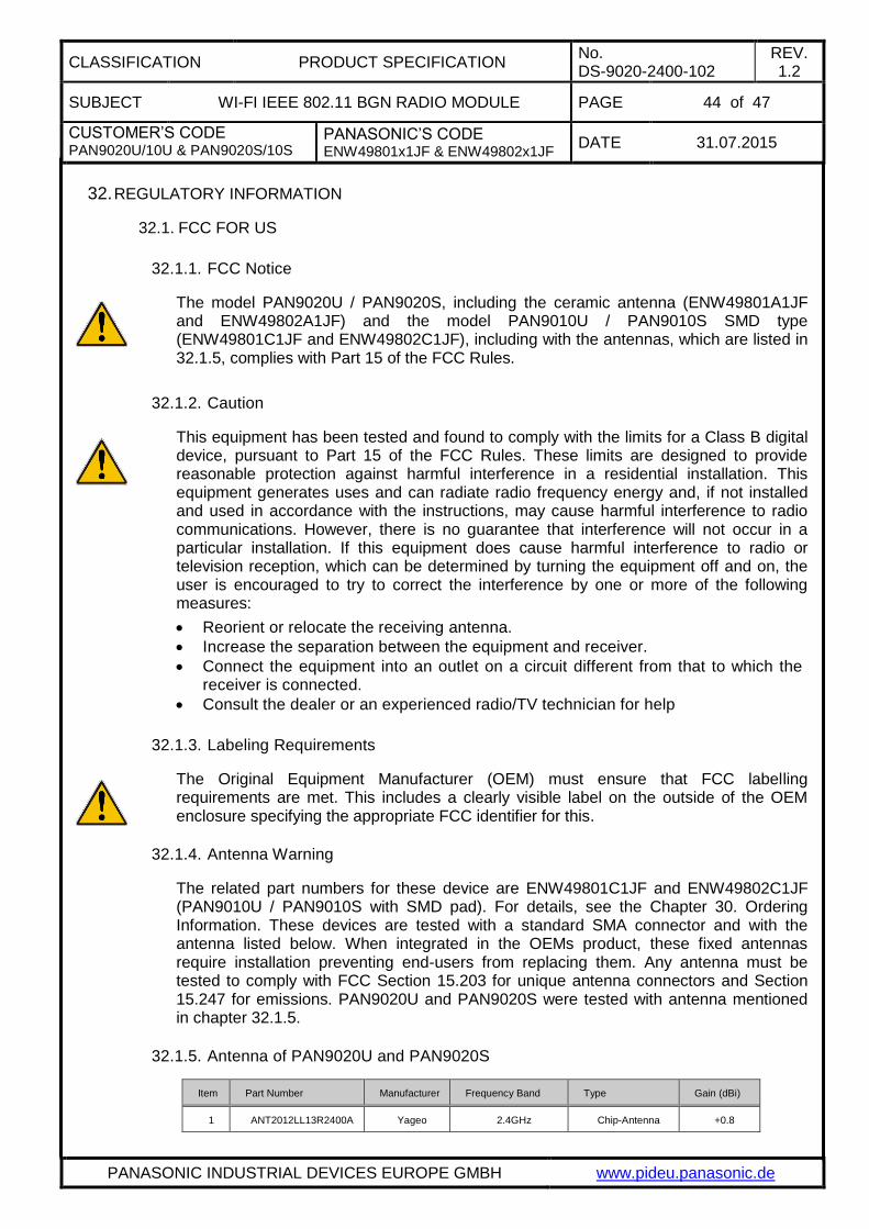
CLASSIFICATION PRODUCT SPECIFICATION No. DS-9020-2400-102
REV. 1.2
SUBJECT WI-FI IEEE 802.11 BGN RADIO MODULE PAGE 44 of 47
CUSTOMER’S CODE PAN9020U/10U & PAN9020S/10S
PANASONIC’S CODE ENW49801x1JF & ENW49802x1JF
DATE 31.07.2015
PANASONIC INDUSTRIAL DEVICES EUROPE GMBH www.pideu.panasonic.de
32. REGULATORY INFORMATION
32.1. FCC FOR US
32.1.1. FCC Notice
The model PAN9020U / PAN9020S, including the ceramic antenna (ENW49801A1JF and ENW49802A1JF) and the model PAN9010U / PAN9010S SMD type (ENW49801C1JF and ENW49802C1JF), including with the antennas, which are listed in 32.1.5, complies with Part 15 of the FCC Rules.
32.1.2. Caution
This equipment has been tested and found to comply with the limits for a Class B digital device, pursuant to Part 15 of the FCC Rules. These limits are designed to provide reasonable protection against harmful interference in a residential installation. This equipment generates uses and can radiate radio frequency energy and, if not installed and used in accordance with the instructions, may cause harmful interference to radio communications. However, there is no guarantee that interference will not occur in a particular installation. If this equipment does cause harmful interference to radio or television reception, which can be determined by turning the equipment off and on, the user is encouraged to try to correct the interference by one or more of the following measures:
Reorient or relocate the receiving antenna.
Increase the separation between the equipment and receiver.
Connect the equipment into an outlet on a circuit different from that to which the receiver is connected.
Consult the dealer or an experienced radio/TV technician for help
32.1.3. Labeling Requirements
The Original Equipment Manufacturer (OEM) must ensure that FCC labelling requirements are met. This includes a clearly visible label on the outside of the OEM enclosure specifying the appropriate FCC identifier for this.
32.1.4. Antenna Warning
The related part numbers for these device are ENW49801C1JF and ENW49802C1JF (PAN9010U / PAN9010S with SMD pad). For details, see the Chapter 30. Ordering Information. These devices are tested with a standard SMA connector and with the antenna listed below. When integrated in the OEMs product, these fixed antennas require installation preventing end-users from replacing them. Any antenna must be tested to comply with FCC Section 15.203 for unique antenna connectors and Section 15.247 for emissions. PAN9020U and PAN9020S were tested with antenna mentioned in chapter 32.1.5.
32.1.5. Antenna of PAN9020U and PAN9020S
Item Part Number Manufacturer Frequency Band Type Gain (dBi)
1 ANT2012LL13R2400A Yageo 2.4GHz Chip-Antenna +0.8

CLASSIFICATION PRODUCT SPECIFICATION No. DS-9020-2400-102
REV. 1.2
SUBJECT WI-FI IEEE 802.11 BGN RADIO MODULE PAGE 45 of 47
CUSTOMER’S CODE PAN9020U/10U & PAN9020S/10S
PANASONIC’S CODE ENW49801x1JF & ENW49802x1JF
DATE 31.07.2015
PANASONIC INDUSTRIAL DEVICES EUROPE GMBH www.pideu.panasonic.de
32.1.6. RF Exposure PAN9020U and PAN9020S
To comply with FCC RF Exposure requirements, the Original Equipment Manufacturer (OEM) must ensure that the antenna in the previous table must be installed.
The preceding statement must be included as a CAUTION statement in manuals for products operating with the antennas in the previous table to alert users on FCC RF Exposure compliance.
Any notification to the end user of installation or removal instructions about the integrated radio module is not allowed.
The radiated output power of PAN9020U / PAN9020S with mounted ceramic chip antenna are far below the FCC radio frequency exposure limits. Nevertheless, the PAN9020U and PAN9020S shall be used in such a manner that the potential for human contact during normal operation is minimized.
End users may not be provided with the module installation instructions. OEM integrators and end users must be provided with transmitter operating conditions for satisfying RF exposure compliance.
32.2. INDUSTRY CANADA CERTIFICATION
PAN9020U and PAN9020S are licensed to meet the regulatory requirements of Industry Canada (IC),
License for USB version: IC: 216Q-9020U
License for SDIO version: IC: 216Q-9020S
Manufacturers of mobile, fixed or portable devices incorporating this module are advised to clarify any regulatory questions and ensure compliance for SAR and/or RF exposure limits. Users can obtain Canadian information on RF exposure and compliance from www.ic.gc.ca.
This device has been designed to operate with the antennas listed in Table 20 above, having a maximum gain of 0.8 dBi. Antennas not included in this list or having a gain greater than 0.8 dBi are strictly prohibited for use with this device. The required antenna impedance is 50 ohms. The antenna used for this transmitter must not be co-located or operating in conjunction with any other antenna or transmitter.
32.2.1. IC Notice
The device PAN9020U / PAN9020S, for details refer to Chapter 30, including the antennas, which are listed in 32.1.5, complies with Canada RSS-GEN Rules. The device meets the requirements for modular transmitter approval as detailed in RSS-GEN.
Operation is subject to the following two conditions:
(1) This device may not cause harmful interference, and
(2) This device must accept any interference received, including interference that may cause undesired operation.
32.2.2. Labeling Requirements
The Original Equipment Manufacturer (OEM) must ensure that IC labelling requirements are met. This includes a clearly visible label on the outside of the OEM enclosure specifying the appropriate Panasonic IC identifier for this product as well as the IC
CLASSIFICATION PRODUCT SPECIFICATION No. DS-9020-2400-102
REV. 1.2
SUBJECT WI-FI IEEE 802.11 BGN RADIO MODULE PAGE 46 of 47
CUSTOMER’S CODE PAN9020U/10U & PAN9020S/10S
PANASONIC’S CODE ENW49801x1JF & ENW49802x1JF
DATE 31.07.2015
PANASONIC INDUSTRIAL DEVICES EUROPE GMBH www.pideu.panasonic.de
Notice above. The IC identifier are: 216Q-9020U for USB version and 216Q-9020S for SDIO version.
This IC identifier is valid for all PAN9020U and PAN9020S, for details, see the Chapter 30. Ordering Information.
In any case the end product must be labelled exterior with "Contains IC: 216Q-9020U" for USB version
"Contains IC: 216Q-9020S" for SDIO version.
Les fabricants d’équipements (OEM) doivent s’assurer que les obligations d’étiquetage du produit final sont remplies. Ces obligations incluent une étiquette clairement visible à l’extérieur de l’emballage externe, comportant l’identifiant IC du module Panasonic inclus, ainsi que la notification ci-dessus.
Les identifiants IC sont: IC: 216Q-9020U (pour USB version)
Les identifiants IC sont: IC: 216Q-9020S (pour SDIO version)
Ces identifiants sont valides pour tous les PAN9020U / PAN9020S (Chapter 30. Ordering Information). Dans tous les cas les produits finaux doivent indiquer sur leur emballage externe une des mentions suivantes:
"Contient IC: 216Q-9020U” (pour USB version)
"Contient IC: 216Q-9020S” (pour SDIO version)
32.3. EUROPEAN R&TTE DECLARATION OF CONFORMITY
All modules described in this data sheet comply to the standards according R&TTE article:
3.1a Safety/Health:
EN60950-1:2006+A11:2009+A1:2010+A12:2011+AC:2011+A2:2013
EN62311:2008
EN62479:2010
3.1b EMC: EN 301 489-1 V1.8.1:2008-04
EN 301 489-17 V2.2.1:2012-09
3.2 Radio: EN 300 328 V1.8.1:2012-06
As a result of the conformity assessment procedure described in Annex III of the Directive 1999/5/EC, the end-customer equipment should be labelled as follows:
The end-customer has to assure that the device has a distance of more than 20cm from the human body under all circumstances.
The end-customer equipment must meet the actual Safety/Health requirements according R&TTE.
PAN9020U / PAN9020S and their model versions in the specified reference design can be used in the following countries: Austria, Belgium, Cyprus, Czech Republic, Denmark, Estonia, Finland, France, Germany, Greece, Hungary, Ireland, Italy, Latvia, Lithuania, Luxembourg, Malta, Poland, Portugal, Slovakia, Slovenia, Spain, Sweden, Netherland, the United Kingdom, Switzerland, and Norway.

CLASSIFICATION PRODUCT SPECIFICATION No. DS-9020-2400-102
REV. 1.2
SUBJECT WI-FI IEEE 802.11 BGN RADIO MODULE PAGE 47 of 47
CUSTOMER’S CODE PAN9020U/10U & PAN9020S/10S
PANASONIC’S CODE ENW49801x1JF & ENW49802x1JF
DATE 31.07.2015
PANASONIC INDUSTRIAL DEVICES EUROPE GMBH www.pideu.panasonic.de
33. GENERAL INFORMATION
© Panasonic Industrial Devices Europe GmbH 2015.
All rights reserved.
This product description does not lodge the claim to be complete and free of mistakes.
Please contact the related product manager in every case.
If we deliver ES samples to the customer, these samples have the status Engineering Samples. This means, the design of this product is not yet concluded. Engineering Samples may be partially or fully functional, and there may be differences to be published Data Sheet.
Engineering Samples are not qualified and are not to be used for reliability testing or series production.
Disclaimer:
Customer acknowledges that samples may deviate from the Data Sheet and may bear defects due to their status of development and the lack of qualification mentioned above.
Panasonic rejects any liability or product warranty for Engineering Samples. In particular, Panasonic disclaims liability for damages caused by
the use of the Engineering Sample other than for Evaluation Purposes, particularly the installation or integration in another product to be sold by Customer,
deviation or lapse in function of Engineering Sample,
improper use of Engineering Samples.
Panasonic Industrial Devices Europe GmbH disclaimes any liability for consequential and incidental damages. In case of any questions, please contact your local sales partner or the related product manager.
34. LIFE SUPPORT POLICY
This Panasonic Industrial Devices Europe GmbH product is not designed for use in life support appliances, devices, or systems where malfunction can reasonably be expected to result in a significant personal injury to the user, or as a critical component in any life support device or system whose failure to perform can be reasonably expected to cause the failure of the life support device or system, or to affect its safety or effectiveness. Customers using or selling these products for use in such applications do so at their own risk and agree to fully indemnify Panasonic Industrial Devices Europe GmbH for any damages resulting.