table of contents - nocoug - northern california … fault-tolerant nas for oracle—the next...
TRANSCRIPT
Scalable, fault-tolerant NAS for Oracle—the next generationIntroducing the HP Enterprise File Services Cluster Gateway for Oracle database deployments
Table of contentsIntroduction . . . . . . . . . . . . . . . . . . . . . . . . . . . . . . . . . . . . . . . . . . . . . . . . . . . . . . . . . . . . . . . . . . . . . . . . . . . . . . . . . . . . . . . . . . . . . . . . . . . . . . 2
HP Enterprise File Services Clustered Gateway . . . . . . . . . . . . . . . . . . . . . . . . . . . . . . . . . . . . . . . . . . . . . . . . . . . . . . . 6
Proof of concept . . . . . . . . . . . . . . . . . . . . . . . . . . . . . . . . . . . . . . . . . . . . . . . . . . . . . . . . . . . . . . . . . . . . . . . . . . . . . . . . . . . . . . . . . . . . . . . 9
Summary . . . . . . . . . . . . . . . . . . . . . . . . . . . . . . . . . . . . . . . . . . . . . . . . . . . . . . . . . . . . . . . . . . . . . . . . . . . . . . . . . . . . . . . . . . . . . . . . . . . . . . . . .19
Appendix . . . . . . . . . . . . . . . . . . . . . . . . . . . . . . . . . . . . . . . . . . . . . . . . . . . . . . . . . . . . . . . . . . . . . . . . . . . . . . . . . . . . . . . . . . . . . . . . . . . . . . . .20
IntroductionFor several years Network Attached Storage (NAS) hasbeen rapidly evolving into an acceptable storage optionfor Oracle® databases. With the advent of Gigabit Ethernetand software advancements in the NFS client space, reasonable performance and solid data integrity are realities on NAS. This is particularly the case when the NFS client is a Linux® system1.
Oracle Corporation has been vocal about its adoption of NAS for the Oracle on Demand outsourcing business.Oracle also has established the Oracle StorageCertification Program (OSCP); whereby vendors canparticipate to prove that their NAS solutions areacceptable for Oracle databases. NAS is quite often the simplest, most cost-effective storage approach forOracle databases.
The emerging storage demand of Grid Computing makesNAS essential. The fruition of Grid Computing will result inconnectivity needs for clusters of servers numbering inhundreds of nodes. Building such a large cluster with aFibre Channel Storage Area Network (SAN) would be a difficult task.
All technology has strengths and weaknesses. With NASfilers, the strong points for Oracle databases are ease ofuse and often cost. Architecturally speaking, however, NASfilers show weaknesses in the areas of availability andscalability. This is a bold statement given the wideacceptance of NAS for Oracle databases. The goal of thispaper is to discuss these characteristics of the NAS filermodel and the emerging technology that addresses the issues.
Without a doubt, the majority of Oracle databasesdeployed on NAS are in the same datacenters with formidable SAN configurations. Supporting two differentstorage architectures can be a cumbersome task for IT
shops. This fact has ushered in the new wave of NASgateway technology—another focus area of this paper.
Finally, choosing SAN, NAS, or both generally is heavilyweighted on performance. To that end, this paper includesan analysis of a proof of concept in which both the availability and performance characteristics of Oracle10gR2 RAC are tested in a new NAS gateway productfrom Hewlett-Packard called the HP Enterprise FileServices Clustered Gateway (EFS-CG).
Goals for the readerAfter reading this paper, the reader should have a deeperunderstanding of many aspects of deploying Oracle on NAS.Additionally, the reader will understand the differencesbetween two traditional NAS architectural approaches:
• Single-headed NAS filers
• Asymmetrical multi-headed NAS gateways
Finally, through a description and analysis of a Proof ofConcept test, the reader will learn about the EFS-CG,which provides:
• Multi-headed (scalable) architecture
• Fully symmetrical operations (all NAS heads can present all filesystems)
• Transparent NFS Client failover (highly available)
The primary goal for the reader is an architectural understanding of the technologies being discussed. Thispaper does not have direct marketing objectives and theonly specific NAS technology discussed by name is thenew technology that serves as the catalyst for the proof-of-concept testing—the HP EFS-CG.
2
Abstract: Now there is scalable, modular, high performance NAS for Oracle®10g RAC and non-RACwith no single point of failure. This proof of conceptshows that the new HP Enterprise File Server ClusteredGateway (EFS-CG) is currently the only scalable, highlyavailable option when NAS is used as the storagearchitecture for Oracle. In fact, the Clustered Gatewayallows customers to leverage existing SAN infrastructuresuch as HP, EMC, and Hitachi Data Systems.
This paper focuses on a proof of concept of Oracle10gR2 Real Application Clusters with the EFS-CG as storagefor all database files, Oracle Clusterware files, OracleHome, and External Tables. It also includes Oracle10gR2 performance results with I/O-intensive Oracleworkloads. With the HP Enterprise File Server ClusteredGateway, the question is no longer SAN or NAS.Depending on application needs, the customer’s choice isalways the right choice.
1Network Appliance and Charles Lever in particular were instrumental inmaking modern NFS client software suitable for Oracle over NFS.
NAS value proposition for Oracledatabase deploymentSimplicityIndustry-leading NAS providers have invested significantlyin educating the industry on the value of deploying Oracledatabases on NAS.
Perhaps the most attractive aspect of deploying Oracledatabases on NAS is simplicity. This is especially the casewhen Real Application Clusters (RAC) are being deployed.System administrators of any Oracle database on NASfind it quite simple to request storage from the storageadministration group and mount the filesystem on thedatabase server. Once the NFS filesystem is mounted, theserver administrator is completely out of the loop forstorage issues. The space is given to the Oracle DBAteam, and they use it as per the requirements of thedatabase—no more interaction with the system or storageadministration groups. Contrast this to the amount ofsystem administrative overhead when deploying Oracledatabases on raw partitions in a SAN.
Whether simple raw datafiles or ASM, administrativeoverhead is required. First, the database administratorhas to determine the list of singleton LUNs needed, suchas the Oracle clusterware files, raw datafiles, or ASM diskgroup partitions. The system administrator then requeststhese LUNs from the storage group and proceeds to workout connectivity, dealing with such issues as loading hostbus adaptors, getting the LUNs presented as characterspecial raw devices, permissions, and in the case of Linux,raw(8) binding and ASMLib configuration. This activity ismuch more complex than mounting filesystems.
With the NAS model, deploying RAC is much simpler forthe DBA than using the typical SAN deployment model2,which is a combination of OCFS2 for Oracle Clusterwareand raw partitions for ASM (or simple raw datafiles), andExt3 or OCFS2 for Oracle Home. With NAS the DBA isnotified when the filesystem is mounted and work can begin.Simple files or large files as ASM disks, the choice is upto the DBA. The DBA can store everything associated withthe Oracle database in the NFS filesystems and all RACservers have complete shared read/write access. There,however, lies the potential performance bottleneck andavailability concerns discussed later in this paper.
Cost reductionDepending on the type of deployment, the NAS modelcan offer significant cost benefit compared to SAN. Certainly, test and development systems running Linux are less expensive when their storage connectivity is basedon NFS instead of SAN volumes. No Fibre Channel HBAsto purchase, no Fibre Channel cabling, and most importantly,no expensive ports on a high-end Fibre Channel switch.NAS-based production systems also can be less expensiveif they are RAC clusters with large node counts. A port ona 64-port Fibre Channel switch is much more expensivethan a port on a small 8-port switch. Accordingly, configuringa RAC cluster for Grid Computing with large numbers ofservers, each with multiple paths to storage, can beextremely cost prohibitive.
Some would argue that the NAS model has reducedadministrative overhead. This is questionable, however,
3
2 The scope of this paper is focused only on deployment options that fit underthe Unbreakable Linux support model—a very short list limited to raw disk(e.g., ASM, raw datafiles) and OCFS. Clearly missing is the comparison to commercially available SAN-based, third-party Cluster filesystems, whichhave their own value propositions but do not fit within the constraints ofUnbreakable Linux. Although third-party CFS are not included in theUnbreakable support model, they can be listed on Metalink as a “validatedthird-party CFS.” None of this concern over Unbreakable Linux amounts toanything unless you are running Linux.
Perhaps the most attractive aspect of deploying Oracledatabases on NAS is simplicity. This is especially thecase when Real Application Clusters (RAC) are being deployed. System administrators of any Oracledatabase on NAS find it quite simple to request storagefrom the storage administration group and simplymount the filesystem on the database server.
because most NAS-based RAC deployments are in ITshops that also have significant SAN investment. Anincrease in storage administration overhead occurs, asthere are disparate storage systems to maintain. Unless, of course, the NAS device is a SAN gateway device.Without a SAN gateway, adding NAS into an environmentwith an established SAN creates the “storage sprawl” or“vendor sprawl” effect.
Traditional NAS As already covered, NAS is an established, acceptablestorage option for Oracle RAC and non-RAC alike.Acceptable, however, is the key word. No technology isperfect and the most popular NAS options being deployedtoday have weaknesses that should be of concern to anOracle shop. The following sections cover two of the mostcommon NAS architectures:
• Single-headed filer
• Asymmetrical multi-headed NAS device
Because this paper does not serve a marketing purpose,vendor names for various architecture types are not used.
Single-headed filers, the traditionalNAS architectureThe most common NAS devices available on the markettoday are “single-headed” devices commonly referred toas filers. The term single-headed means that there is a single computer with a processor, memory, and I/O capability handling all accesses to a set of filesystems ondisk. These filers are powerful but because of theirarchitecture they possess two troubling characteristics:
• Single point of failure
• Performance bottleneck
Single point of failureHaving data that can only be accessed through a singlefiler is a single point of failure (SPOF) that cannot be overlooked. If that data is Oracle Clusterware files (e.g.,Oracle10g RAC CRS, Oracle9i OCMS) or any OracleSYSTEM tablespace, a single failure of the filer head willcause a total RAC outage. RAC is highly available, butthe storage really is not. Some mitigating solutions for thissingle point of failure are presented later in this paper.
Performance bottleneckMany Oracle databases are deployed today on single-headed NAS devices. However, if all data must passthrough a single filer for a given set of data, the entiredatabase performance is limited to the throughput of that single filer.
In the case of RAC, few nodes are needed to saturatecompletely a single-headed filer. The reason is that on theinside, the leading single-headed filers are based on thesame Intel®-based servers typically used for Linux RAC. Ifyou peel away the covers on today’s leading NAS filer, youwill see an Intel-based server. If you deploy a four-nodeRAC configuration with Xeon™-based servers and place thedatabase in the filer, you may experience a bottleneck.The Xeon-based system in the filer cannot move more dataacross its system bus than any of the Xeon-based serversin the RAC configuration. So, given an I/O intensiveoperation such as any Parallel Query operation, the RACnodes will be I/O constrained.
What if the database servers attached to the filer aresignificantly more capable of I/O than the filer? Considera four-node RAC configuration of four-socket, dual-coreAMD Opteron™ Servers. How scalable is that going to be?What about just a single large SMP from any manufacturer?The simple answer to these rhetorical questions is that theconfiguration will not scale.
4
Mitigating solutions for single-headed filer issuesTo address the inherent single point of failure issues withsingle-headed filers, some vendors offer clustered filers. Theterm “clustered filer” conjures up a lot of misconceptions.Cluster filers are just that, a cluster of single-headed filers.Neither can provide access to the other’s data.
So, to mitigate the impact of a failure of a NAS filer, thesuggested remedy is to buy another equal filer and configure a cluster filer. Once the investment has beenmade in 100% overhead, the configuration can supportfailover in the event of a filer outage.
Failover, in the case of a cluster of single-headed filers, isa non-surgical procedure known as “sever and reattach”because the NFS handles are usually invalided on the clientafter a filer failure3. The client can, however, remount thefilesystems from the other filer after some failover time—generally 45 to 180 seconds. Sever and reattach shouldimmediately raise concern. In the case of RAC, Oracletreats this as any ordinary loss of storage—akin to asingle array failure in a Storage Area Network (SAN). Butunlike the single array SAN scenario, the clustered filerconfiguration should have no single point of failure.However, if the NAS filer presenting the most importantapplication table happens to fail, the files will not beavailable until cluster failover is complete, and even then theinstances will have to restart. While RAC supports multipleinstances of a database, there is only one database. Lossof I/O connectivity to any of it is a single point of failure.
Clustered filers can help mitigate the performancebottleneck inherent in single-headed filers, to a degree.Clustered filers can be configured such that one filerserves a set of filesystems and the other a completely
separate set of filesystems—basically, a partitioning effort.If I/O demand on a single directory is saturating a filer,no solution is available other than to move data manuallybetween filers. What if the hot data is not the same hotdata that saturates the filer six months from now?
Asymmetrical multi-headed NAS Asymmetrical multi-headed NAS (AMHN) devices are notfilers, per se. They are generally SAN-gateway devices.Because you probably have a SAN already, you simplyrequest LUNs from the storage group and attach the LUNsto the gateway device. From there, the SAN gatewaydevice presents filesystems as would any other NAS device.
Availability Asymmetrical multi-headed NAS devices are similar toclustered single-headed filers but differ in one significantway—they support more than two NAS heads. All NASheads in these devices do indeed have connectivity to allfilesystems, but only one NAS head can present a filesystemat any given time. Therefore, this architecture is deemedasymmetrical. For instance, in a configuration with eightNAS heads and eight filesystems, each filesystem can bepresented by only one NAS head at a time. In the eventof a NAS head outage, the filesystem will fail over to oneof the other heads. The similarities, conversely, betweenasymmetrical multi-headed NAS and clustered single-headed filers are easily seen.
Just like their clustered single-headed cousins, these NASdevices also suffer a sever and reattach impact in theevent of a head failure. Failovers are no more transparentthan they are with clustered single-headed filers. Failover times on these devices can be quite long. Duringfailover, database files in the filesystem being failed-overare inaccessible.
ScalabilityAsymmetrical multi-headed NAS devices have the samescalability characteristics as clustered single-headed filers.As mentioned above, only a single NAS head can presentany given filesystem. As is the case with clustered single-headed filers, the game of moving hot data around toother filesystems to offload over-burdened NAS heads isvery much the case.
From an architecture standpoint, the only differencebetween clustered single-headed filers and asymmetricalmulti-headed NAS devices is that the latter supports morethan two heads. They are more modular but still requirephysically partitioning data between filesystems toachieve a crude form of scalability.
5
3 “Often, the transfer of data service is transparent to end users and applications”http://www.netapp.com/products/software/clustered.html
A word about NVRAM cache:The most common single-headed filers on the market offer anNVRAM cache that dramatically lowers the I/O latency forwrites. These NVRAM cache cards are attached to the filersystem bus. While they do allow writes to be serviced quickly,they do not address the throughput limitation of the filer at all.Quite the opposite is true. When the NVRAM cache is full,I/O requests will queue up while the cache is beingcheckpointed out to disk. Some productions sites mustdedicate a filer solely for Oracle Redo Logging for this reason.
HP Enterprise File ServicesClustered GatewayOverviewHP Enterprise File Services Clustered Gateway, or EFS-CG, isa new and radically different NAS technology from thosealready discussed in this paper. The key differences betweenthe EFS-CG and both clustered single-headed filers andasymmetrical multi-headed NAS devices are explained inTable 1 above.
The EFS-CG is a SAN gateway NAS device. Often this isseen as investment protection. After all, as mentionedpreviously in this paper, most sites that deploy Oracletoday on NAS filers do so in the same datacenter wherethere is an existing, formidable SAN infrastructure. Such anenvironment is the perfect infrastructure for deploying aSAN gateway product like the EFS-CG. The EFS-CG plugsinto the SAN (e.g., HP, EMC, Hitachi, IBM, etc.) andpresents clustered filesystems via NFS. This is an entirelydifferent scenario than carting in a pair of clustered NASfilers with their own internal storage and setting them nextto the existing SAN equipment.
Presenting NAS storage through a gateway device froman established SAN infrastructure can be significantly lessexpensive than the same capacity in a set of NAS filers.This point deserves more attention.
Choosing a NAS model for RAC over SAN usually yieldscost savings because the RAC nodes themselves do notrequire multiple Fibre Channel host bus adaptors withpaths to multiple switches. Fewer servers connected toSAN switches can potentially alleviate the need topurchase extremely large switches. However, the net gainof these savings is canceled out if the storage itself ismore expensive on a per-terabyte basis. With clusteredNAS filers (single-headed), the cost of storage also mustreflect the clustering architecture they support. With clustered
single-headed filers, clustering is limited to “pair-wise”clusters. If both filers in a clustered filer configurationbecome saturated, adding a third filer actually meansadding two more filers—if availability is a concern.Recent analysis of published list prices for industry-leadingclustered NAS filers revealed customers pay approximately300% premium as compared to equal capacity via EFS-CG technology, thus being threefold more costly and notscalable, nor truly available as explained earlier.
Availability characteristicsThe EFS-CG provides a truly revolutionary NFS serverimplementation with special support for highly availableNFS. All NFS export groups are presented to NFS clientsvia Virtual NFS Service (VNFS). The VNFS technology isimportant for two reasons:
• Failover. If a NAS head in the EFS-CG fails, the VirtualNFS Services running on the failed nodes will betransparently failed over to a backup NAS head. TheNFS clients and the processes with open file handles onthe filesystems involved will not be affected in any way.
• Re-hosting. Using the EFS-CG Management GUI or CLI,the administrator can move an active NFS service fromone NAS head to the other for load balancing ormaintenance. This operation also is fully transparent atthe NFS client level and you do not need to stopapplications—just a simple GUI drag and drop.
A VNFS is a combination of Virtual Host IP and aproprietary enhancement to the NFS server stack tosupport completely transparent NFS client failover. Thefilesystems remain accessible without re-mounting and,most importantly, processes with active file handlesaccessing files in the NFS filesystems are not impacted.
6
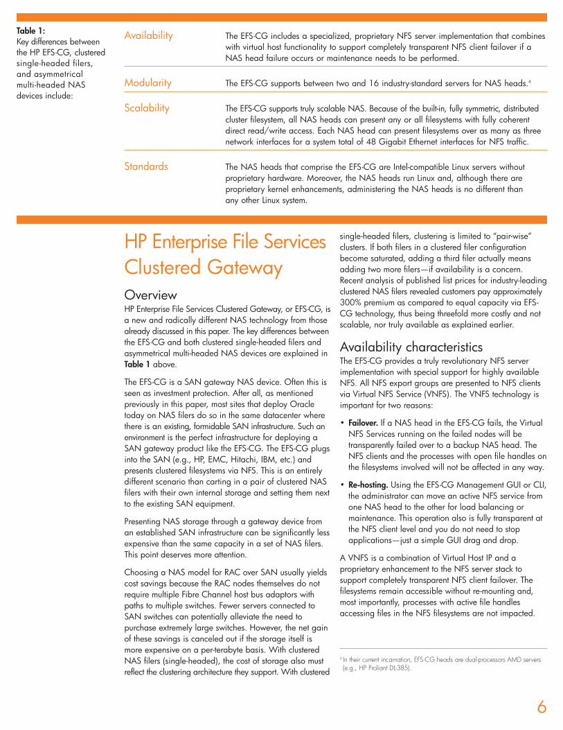
Availability The EFS-CG includes a specialized, proprietary NFS server implementation that combineswith virtual host functionality to support completely transparent NFS client failover if a NAS head failure occurs or maintenance needs to be performed.
Modularity The EFS-CG supports between two and 16 industry-standard servers for NAS heads.4
Scalability The EFS-CG supports truly scalable NAS. Because of the built-in, fully symmetric, distributed cluster filesystem, all NAS heads can present any or all filesystems with fully coherent direct read/write access. Each NAS head can present filesystems over as many as three network interfaces for a system total of 48 Gigabit Ethernet interfaces for NFS traffic.
Standards The NAS heads that comprise the EFS-CG are Intel-compatible Linux servers without proprietary hardware. Moreover, the NAS heads run Linux and, although there are proprietary kernel enhancements, administering the NAS heads is no different than any other Linux system.
Table 1: Key differences betweenthe HP EFS-CG, clusteredsingle-headed filers, and asymmetrical multi-headed NASdevices include:
4 In their current incarnation, EFS-CG heads are dual-processors AMD servers(e.g., HP Proliant DL-385).

The benefit of this technology in an Oracle deploymentshould be quite clear. As discussed earlier, placing anOracle database in a NAS device other than the EFS-CGleaves a single point of failure. All other NAS technologycompletely disconnects all NFS clients in a failover event,whether on clustered filers or asymmetrical multi-headedfilers. If a NAS head presenting datafiles should fail, theseother NAS technologies will cause a global RAC meltdown.With RAC there is one copy of the database and sufferinga “sever and reattach” sort of NAS head failure will impactevery instance of the RAC cluster. This fact does not playwell into the grid computing story. Imagine a 48-nodeRAC grid with 48 instances crashed because the NAShead presenting an essential tablespace has crashed.
Figure 1 shows a portion of the EFS-CG managementGUI. On the horizontal plane are a set of Virtual NFSServices. On the right-hand side along the vertical planeare the NAS heads by name. In this case there are fourNAS heads (c1n1 – c1n4). This screen capture was takenfrom the Proof of Concept system described later in thispaper and shows the status of the Virtual NFS Services.
For instance, the VNFS called vnfs1, and therefore all thefilesystems being presented by vnfs1, are currently hostedby NAS head number 1 (c1n1). This status is established
by the cell for that row, which shows P for primary, underthe c1n1 column. VNFS1 will fail over to c1n4 becausethe numeral 1, short for first backup, appears under thec1n4 column for that same row. Also, the VNFS calledvnfs3b and vnfs2 concurrently are hosted by NAS headnumber 2 (c1n2). Re-hosting a VNFS from one node tothe other is a simple click, drag-and-drop operation.
Figure 2 depicts the transparent nature of the EFS-CGVirtual NFS Service technology. This Linux session shows three clear signs of transparent Virtual NFSfailover/re-hosting.
Figure 2 ends by validating that the shell process still hasa PID of 6553 and still is executing in /u03, which is an NFSmount. The shell process (6553) has at least one active filedescriptor in its current working directory (CWD), which ishow bash(1) works. The shell process was uninterruptedwhile the presentation of /u03 was moved from one NAShead to another. If /u03 were being served up by a clusterof single-headed filers or an asymmetrical multi-headedfiler, the shell process 6553 would have died. Instead, thebash process was unaffected during the 37 seconds when/u03 moved from one NAS head to another.
7
Figure 1: Enterprise File Services Cluster Gateway graphical user interface

Performance characteristicsCluster Volume ManagerThe EFS-CG includes an integrated Cluster VolumeManager. LUNs are presented to the EFS-CG by the SANadministrator and imported into the EFS-CG. Internal tothe EFS-CG, these LUNs are then made into a striped(RAID 0) volume of user-defined stripe width. The LUNsare fault tolerant (e.g., RAID 1) at the SAN storage arraylevel. The EFS-CG can support single Cluster Volumes ofup to 16TB of redundant, high-performance (RAID 1+0)storage. The size of cluster volumes can be dynamicallyincreased. Additionally, the EFS-CG supports largenumbers of filesystems—up to a maximum theoretical limit of 512 16TB filesystems.
Cluster filesystemAll NAS devices available today present an internalfilesystem of some sort via NFS. In the case of the EFS-CG, the filesystem is the PolyServeTM Matrix Server™cluster filesystem, which is fully symmetric and distributed.This means that all NAS heads have equal, direct read/write access to all filesystems. Combining the clusterfilesystem with the cluster volume manager is the foundationfor the tremendous scalability this architecture offers.
Without the cluster filesystem, the EFS-CG would be nodifferent than asymmetrical multi-headed NAS devices onthe market today. The net effect would be that only asingle NAS head would be able to present any givenfilesystem. The cluster filesystem is the glue that enablestrue scalability. Also, the size of EFS-CG cluster filesystemscan be dynamically increased.
NAS head count As mentioned above, the EFS-CG supports from 2 to16NAS heads. When the cluster filesystem is combined withthe cluster volume manager, a single filesystem (up to16TB) can be presented by up to 16 NAS heads, eachwith coherent, direct read/write access.
Network interfacesEach NAS head in the EFS-CG supports several GigabitEthernet network interfaces. Up to three interfaces can beused for serving NFS traffic. A fully configured EFS-CGwith 16 nodes will support up to 48 GigE data paths toone or more filesystems.
The EFS-CG technology can be deployed on any industrystandard server. No technical reason prevents thedeployment of extremely powerful servers such as the HPProliant DL-585 for use as NAS heads, which wouldsupport as many as 12 NFS I/O paths per NAS head.
8
Figure 2Determining which EFS-CG NAS head is presenting a filesystem; re-hosting operations
• First arrow. The session first establishes that:– The shell Process Id (PID) is 6553
– The shell is executing on the RAC node called rac1 (NFS client)
A df(1) command then shows that /u03 is presented by the EFS-CG via the Virtual NFS Service called vnfs1b.
• Second arrow. The uname(1) command is executed remotely (viathe ssh(1)5) on the EFS-CG NAS head that is currently hosting thevnfs1b Virtual NFS Service. The uname(1) command shows thatthe /u03 filesystem is being presented from cln4, the fourth NAShead in the EFS-CG.
• Third arrow. Sometime between 19:56:21 and 19:56:58, thevnfs1b Virtual NFS service was either failed-over or re-hosted tocln1, the first NAS head in the EFS-CG.
5 The NAS Heads are Linux servers and all Linux tools are at the administrator’sdisposal. This environment is much more flexible than that available to theadministrator when connected to proprietary Operating Systems running ontraditional NAS filers.
Bringing it all together—in an Oracle contextPerhaps the best way to elaborate on the potential for theEFS-CG in an Oracle deployment is to look at the extremes.Consider that a single Oracle10g BIGFILE tablespace,based upon a 4KB blocksize, can grow to 16TB. Thecaveat is that a BIGFILE tablespace is comprised of asingle datafile. A single file must reside in a single filesystem.The EFS-CG is capable of supporting the 16TB BIGFILEtablespace, but it can do so with I/O scalability. Everysingle block of data in that one BIGFILE tablespace canbe concurrently accessed through 48 network interfacesvia 16 NAS heads.
Further, the EFS-CG can support a 48-node RAC clusterwhere each and every server has a dedicated GigE NFSdata path with full read/write capability on the entire16TB BIGFILE tablespace. If every instance in the 48-nodeRAC cluster were performing a full-table scan of a table inthat BIGFILE tablespace, their I/O would be serviced atfull GigE bandwidth. If all 48 nodes of the RAC clusterwere participating in an index creation using Intra-nodeParallel Query, nothing stands in the way of having theentire index reside in a single datafile.
This example should make the contrast clear between theEFS-CG and other NAS technology. Other NAS technologyneeds to cluster and split the tablespace across severalfilesystems to get multiple NAS heads to partake in theI/O load—each filesystem served by a single NAS head.However, a BIGFILE tablespace cannot be split intomultiple datafiles anyway, so the comparison is moot. Nosolutions, other than the EFS-CG, can scale to 16 NASheads at all, much less in a symmetrical manner.
This example is beyond the “normal” Oracle deploymentand BIGFILE tablespaces are not the norm but sheds lighton how ASM on NAS works.
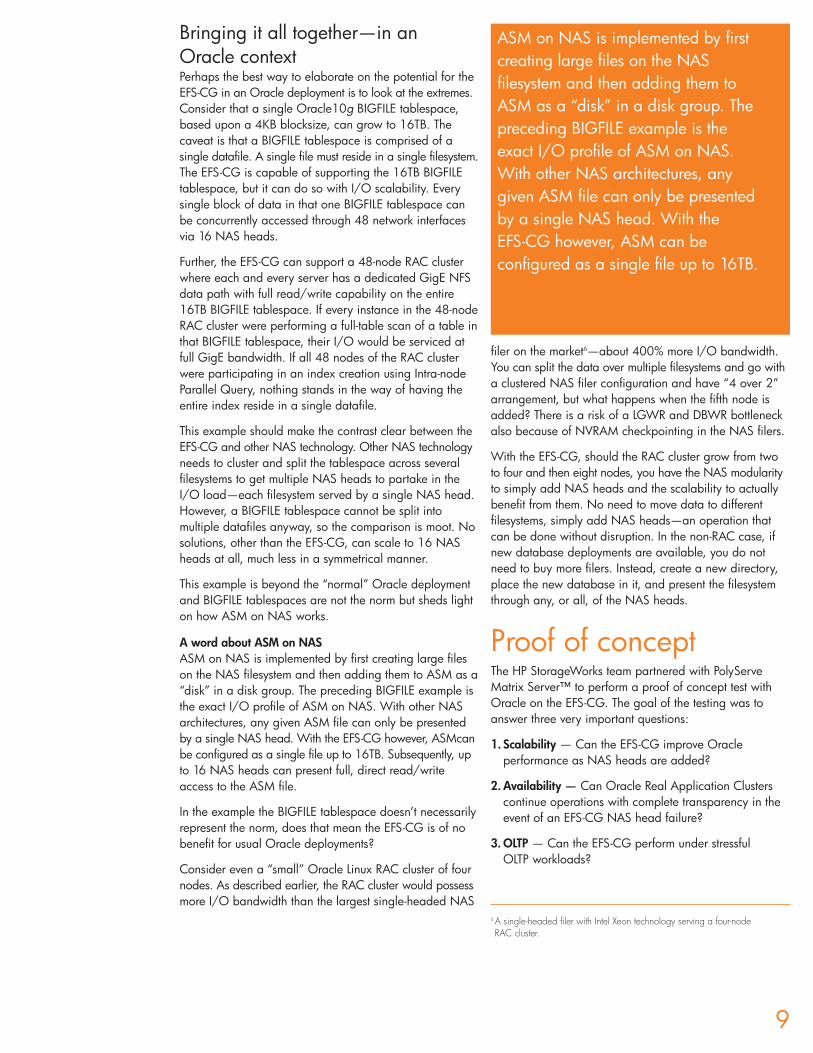
A word about ASM on NASASM on NAS is implemented by first creating large fileson the NAS filesystem and then adding them to ASM as a“disk” in a disk group. The preceding BIGFILE example isthe exact I/O profile of ASM on NAS. With other NASarchitectures, any given ASM file can only be presentedby a single NAS head. With the EFS-CG however, ASMcanbe configured as a single file up to 16TB. Subsequently, upto 16 NAS heads can present full, direct read/writeaccess to the ASM file.
In the example the BIGFILE tablespace doesn’t necessarilyrepresent the norm, does that mean the EFS-CG is of nobenefit for usual Oracle deployments?
Consider even a “small” Oracle Linux RAC cluster of fournodes. As described earlier, the RAC cluster would possessmore I/O bandwidth than the largest single-headed NAS
filer on the market6—about 400% more I/O bandwidth.You can split the data over multiple filesystems and go witha clustered NAS filer configuration and have “4 over 2”arrangement, but what happens when the fifth node isadded? There is a risk of a LGWR and DBWR bottleneckalso because of NVRAM checkpointing in the NAS filers.
With the EFS-CG, should the RAC cluster grow from twoto four and then eight nodes, you have the NAS modularityto simply add NAS heads and the scalability to actuallybenefit from them. No need to move data to differentfilesystems, simply add NAS heads—an operation thatcan be done without disruption. In the non-RAC case, ifnew database deployments are available, you do notneed to buy more filers. Instead, create a new directory,place the new database in it, and present the filesystemthrough any, or all, of the NAS heads.
Proof of conceptThe HP StorageWorks team partnered with PolyServeMatrix Server™ to perform a proof of concept test withOracle on the EFS-CG. The goal of the testing was toanswer three very important questions:
1. Scalability — Can the EFS-CG improve Oracleperformance as NAS heads are added?
2. Availability — Can Oracle Real Application Clusterscontinue operations with complete transparency in theevent of an EFS-CG NAS head failure?
3. OLTP — Can the EFS-CG perform under stressful OLTP workloads?
9
ASM on NAS is implemented by firstcreating large files on the NASfilesystem and then adding them to ASM as a “disk” in a disk group. Thepreceding BIGFILE example is the exact I/O profile of ASM on NAS. With other NAS architectures, any given ASM file can only be presentedby a single NAS head. With the EFS-CG however, ASM can beconfigured as a single file up to 16TB.
6 A single-headed filer with Intel Xeon technology serving a four-node RAC cluster.
10
/u01/u02
/u03
/u04
/u01
CGWNode
vnfs1
/u03
/u04
CGWNode
/u03
/u04
CGWNode
/u02
CGWNode
Enterprise File Services Clustered Gateway
vnfs1b vnfs2b vnfs3b
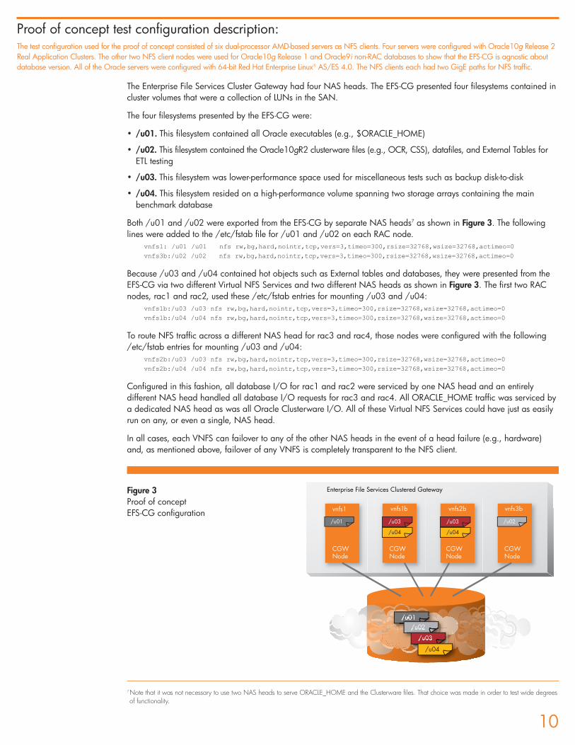
The Enterprise File Services Cluster Gateway had four NAS heads. The EFS-CG presented four filesystems contained incluster volumes that were a collection of LUNs in the SAN.
The four filesystems presented by the EFS-CG were:
• /u01. This filesystem contained all Oracle executables (e.g., $ORACLE_HOME)
• /u02. This filesystem contained the Oracle10gR2 clusterware files (e.g., OCR, CSS), datafiles, and External Tables forETL testing
• /u03. This filesystem was lower-performance space used for miscellaneous tests such as backup disk-to-disk
• /u04. This filesystem resided on a high-performance volume spanning two storage arrays containing the mainbenchmark database
Both /u01 and /u02 were exported from the EFS-CG by separate NAS heads7 as shown in Figure 3. The followinglines were added to the /etc/fstab file for /u01 and /u02 on each RAC node.
vnfs1: /u01 /u01 nfs rw,bg,hard,nointr,tcp,vers=3,timeo=300,rsize=32768,wsize=32768,actimeo=0
vnfs3b:/u02 /u02 nfs rw,bg,hard,nointr,tcp,vers=3,timeo=300,rsize=32768,wsize=32768,actimeo=0
Because /u03 and /u04 contained hot objects such as External tables and databases, they were presented from theEFS-CG via two different Virtual NFS Services and two different NAS heads as shown in Figure 3. The first two RACnodes, rac1 and rac2, used these /etc/fstab entries for mounting /u03 and /u04:
vnfs1b:/u03 /u03 nfs rw,bg,hard,nointr,tcp,vers=3,timeo=300,rsize=32768,wsize=32768,actimeo=0
vnfs1b:/u04 /u04 nfs rw,bg,hard,nointr,tcp,vers=3,timeo=300,rsize=32768,wsize=32768,actimeo=0
To route NFS traffic across a different NAS head for rac3 and rac4, those nodes were configured with the following/etc/fstab entries for mounting /u03 and /u04:
vnfs2b:/u03 /u03 nfs rw,bg,hard,nointr,tcp,vers=3,timeo=300,rsize=32768,wsize=32768,actimeo=0
vnfs2b:/u04 /u04 nfs rw,bg,hard,nointr,tcp,vers=3,timeo=300,rsize=32768,wsize=32768,actimeo=0
Configured in this fashion, all database I/O for rac1 and rac2 were serviced by one NAS head and an entirelydifferent NAS head handled all database I/O requests for rac3 and rac4. All ORACLE_HOME traffic was serviced bya dedicated NAS head as was all Oracle Clusterware I/O. All of these Virtual NFS Services could have just as easilyrun on any, or even a single, NAS head.
In all cases, each VNFS can failover to any of the other NAS heads in the event of a head failure (e.g., hardware)and, as mentioned above, failover of any VNFS is completely transparent to the NFS client.
Proof of concept test configuration description:The test configuration used for the proof of concept consisted of six dual-processor AMD-based servers as NFS clients. Four servers were configured with Oracle10g Release 2Real Application Clusters. The other two NFS client nodes were used for Oracle10g Release 1 and Oracle9i non-RAC databases to show that the EFS-CG is agnostic aboutdatabase version. All of the Oracle servers were configured with 64-bit Red Hat Enterprise Linux® AS/ES 4.0. The NFS clients each had two GigE paths for NFS traffic.
Figure 3Proof of conceptEFS-CG configuration
7Note that it was not necessary to use two NAS heads to serve ORACLE_HOME and the Clusterware files. That choice was made in order to test wide degreesof functionality.
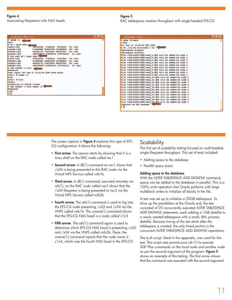
The screen capture in Figure 4 explores this type of EFS-CG configuration. It shows the following:
• First arrow. The session starts by showing that it is aLinux shell on the RAC node called rac1
• Second arrow. A df(1) command on rac1 shows that/u04 is being presented to this RAC node via theVirtual NFS Service called vnfs1b
• Third arrow. A df(1) command, executed remotely viarsh(1), on the RAC node called rac3 shows that the/u04 filesystem is being presented to rac3 via theVirtual NFS Service called vnfs2b
• Fourth arrow. The ssh(1) command is used to log intothe EFS-CG node presenting /u03 and /u04 via theVNFS called vnfs1b. The uname(1) command showsthat the EFS-CG NAS head is a node called c1n3
• Fifth arrow. The ssh(1) command again is used todetermine which EFS-CG NAS head is presenting /u03and /u04 via the VNFS called vnfs2b. There, theuname(1) command reports that the node name isc1n4, which was the fourth NAS head in the EFS-CG
ScalabilityThe first set of scalability testing focused on multi-headed,single filesystem throughput. This set of tests included:
• Adding space to the database
• Parallel query scans
Adding space to the databaseWith the ALTER TABLESPACE ADD DATAFILE command,space can be added to the database in parallel. This is a100% write operation that Oracle performs with largemultiblock writes to initialize all blocks in the file.
A test was set up to initialize a 20GB tablespace. To drive up the parallelism at the Oracle end, the testconsisted of 20 concurrently executed ALTER TABLESPACEADD DATAFILE statements, each adding a 1GB datafile toa newly created tablespace with a small, 8M, primarydatafile. Because timing of the test starts after thetablespace is created, the only timed portion is theconcurrent ALTER TABLESPACE ADD DATAFILE operations.
The ts.sh script, listed in the appendix, was used for thistest. This script uses promiscuous rsh (1) to executeSQL*Plus commands on the local node and another nodeas per the second argument of the program. Figure 5shows an example of this testing. The first arrow showsthat the command was executed with the second argument
11
Figure 4Associating filesystems with NAS heads
Figure 5RAC tablespace creation throughput with single-headed EFS-CG
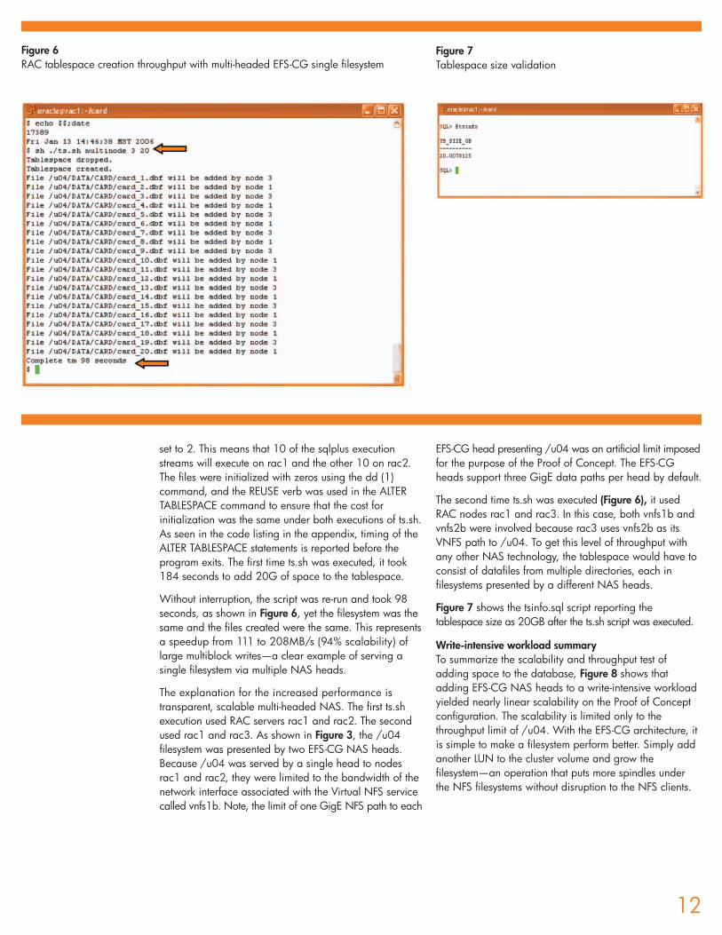
set to 2. This means that 10 of the sqlplus executionstreams will execute on rac1 and the other 10 on rac2.The files were initialized with zeros using the dd (1)command, and the REUSE verb was used in the ALTERTABLESPACE command to ensure that the cost forinitialization was the same under both executions of ts.sh.As seen in the code listing in the appendix, timing of theALTER TABLESPACE statements is reported before theprogram exits. The first time ts.sh was executed, it took184 seconds to add 20G of space to the tablespace.
Without interruption, the script was re-run and took 98seconds, as shown in Figure 6, yet the filesystem was thesame and the files created were the same. This representsa speedup from 111 to 208MB/s (94% scalability) oflarge multiblock writes—a clear example of serving asingle filesystem via multiple NAS heads.
The explanation for the increased performance istransparent, scalable multi-headed NAS. The first ts.shexecution used RAC servers rac1 and rac2. The secondused rac1 and rac3. As shown in Figure 3, the /u04filesystem was presented by two EFS-CG NAS heads.Because /u04 was served by a single head to nodesrac1 and rac2, they were limited to the bandwidth of thenetwork interface associated with the Virtual NFS servicecalled vnfs1b. Note, the limit of one GigE NFS path to each
EFS-CG head presenting /u04 was an artificial limit imposedfor the purpose of the Proof of Concept. The EFS-CGheads support three GigE data paths per head by default.
The second time ts.sh was executed (Figure 6), it usedRAC nodes rac1 and rac3. In this case, both vnfs1b andvnfs2b were involved because rac3 uses vnfs2b as itsVNFS path to /u04. To get this level of throughput withany other NAS technology, the tablespace would have toconsist of datafiles from multiple directories, each infilesystems presented by a different NAS heads.
Figure 7 shows the tsinfo.sql script reporting thetablespace size as 20GB after the ts.sh script was executed.
Write-intensive workload summaryTo summarize the scalability and throughput test ofadding space to the database, Figure 8 shows thatadding EFS-CG NAS heads to a write-intensive workloadyielded nearly linear scalability on the Proof of Conceptconfiguration. The scalability is limited only to thethroughput limit of /u04. With the EFS-CG architecture, itis simple to make a filesystem perform better. Simply addanother LUN to the cluster volume and grow thefilesystem—an operation that puts more spindles underthe NFS filesystems without disruption to the NFS clients.
12
Figure 6RAC tablespace creation throughput with multi-headed EFS-CG single filesystem
Figure 7Tablespace size validation
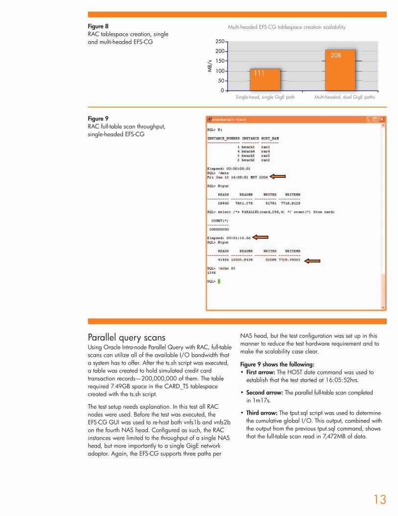
Parallel query scansUsing Oracle Intra-node Parallel Query with RAC, full-tablescans can utilize all of the available I/O bandwidth that a system has to offer. After the ts.sh script was executed, a table was created to hold simulated credit cardtransaction records—200,000,000 of them. The tablerequired 7.49GB space in the CARD_TS tablespacecreated with the ts.sh script.
The test setup needs explanation. In this test all RACnodes were used. Before the test was executed, the EFS-CG GUI was used to re-host both vnfs1b and vnfs2bon the fourth NAS head. Configured as such, the RACinstances were limited to the throughput of a single NAShead, but more importantly to a single GigE networkadaptor. Again, the EFS-CG supports three paths per
NAS head, but the test configuration was set up in thismanner to reduce the test hardware requirement and tomake the scalability case clear.
Figure 9 shows the following:• First arrow: The HOST date command was used to
establish that the test started at 16:05:52hrs.
• Second arrow: The parallel full-table scan completed in 1m17s.
• Third arrow: The tput.sql script was used to determinethe cumulative global I/O. This output, combined withthe output from the previous tput.sql command, showsthat the full-table scan read in 7,472MB of data.
13
Figure 9RAC full-table scan throughput,single-headed EFS-CG
Figure 8RAC tablespace creation, singleand multi-headed EFS-CG
111
208
0
50
100
150
200
250
MB/
s
Multi-headed EFS-CG tablespace creation scalability
Single-head, single GigE path Multi-headed, dual GigE paths
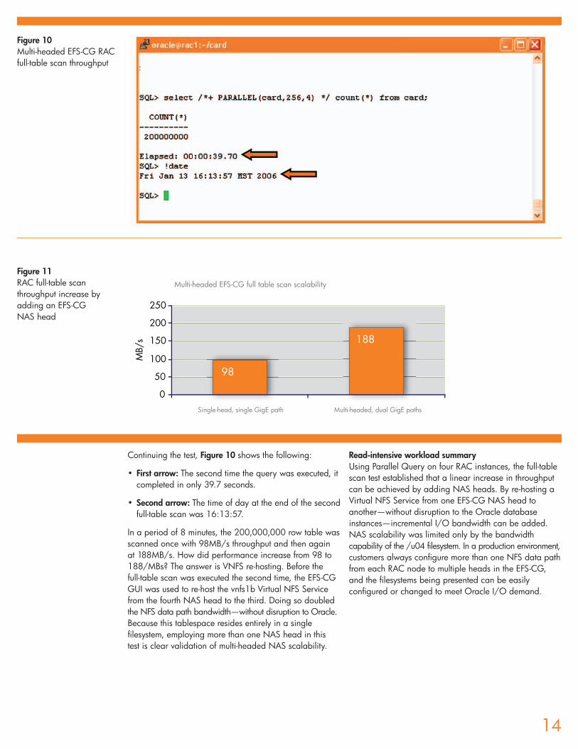
Continuing the test, Figure 10 shows the following:
• First arrow: The second time the query was executed, itcompleted in only 39.7 seconds.
• Second arrow: The time of day at the end of the second full-table scan was 16:13:57.
In a period of 8 minutes, the 200,000,000 row table wasscanned once with 98MB/s throughput and then again at 188MB/s. How did performance increase from 98 to188/MBs? The answer is VNFS re-hosting. Before the full-table scan was executed the second time, the EFS-CGGUI was used to re-host the vnfs1b Virtual NFS Servicefrom the fourth NAS head to the third. Doing so doubledthe NFS data path bandwidth—without disruption to Oracle.Because this tablespace resides entirely in a singlefilesystem, employing more than one NAS head in this test is clear validation of multi-headed NAS scalability.
Read-intensive workload summaryUsing Parallel Query on four RAC instances, the full-tablescan test established that a linear increase in throughputcan be achieved by adding NAS heads. By re-hosting aVirtual NFS Service from one EFS-CG NAS head toanother—without disruption to the Oracle databaseinstances—incremental I/O bandwidth can be added.NAS scalability was limited only by the bandwidthcapability of the /u04 filesystem. In a production environment,customers always configure more than one NFS data pathfrom each RAC node to multiple heads in the EFS-CG,and the filesystems being presented can be easilyconfigured or changed to meet Oracle I/O demand.
14
98
188
0
50
100
150
200
250
MB/
s
Figure 10Multi-headed EFS-CG RACfull-table scan throughput
Figure 11 RAC full-table scanthroughput increase byadding an EFS-CG NAS head
Multi-headed EFS-CG full table scan scalability
Single-head, single GigE path Multi-headed, dual GigE paths
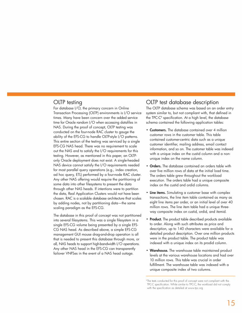
OLTP testingFor database I/O, the primary concern in OnlineTransaction Processing (OLTP) environments is I/O servicetimes. Many have been concern over the added servicetime for Oracle random I/O when accessing datafiles inNAS. During the proof of concept, OLTP testing wasconducted on the four-node RAC cluster to gauge theability of the EFS-CG to handle OLTP-style I/O patterns.This entire section of the testing was serviced by a singleEFS-CG NAS head. There was no requirement to scaleout the NAS end to satisfy the I/O requirements for thistesting. However, as mentioned in this paper, an OLTP-only Oracle deployment does not exist. A single-headedNAS device cannot satisfy the I/O requirements neededfor most parallel query operations (e.g., index creation,ad hoc query, ETL) performed by a four-node RAC cluster.Any other NAS offering would require the partitioning ofsome data into other filesystems to present the datathrough other NAS heads. If intentions were to partitionthe data, Real Application Clusters would not have beenchosen. RAC is a scalable database architecture that scalesby adding nodes, not by partitioning data—the samescaling paradigm as the EFS-CG.
The database in this proof of concept was not partitionedinto several filesystems. This was a single filesystem in asingle EFS-CG volume being presented by a single EFS-CG NAS head. As described above, a simple EFS-CGmanagement GUI mouse drag-and-drop operation is allthat is needed to present this database through more, orall, NAS heads to support high-bandwidth I/O operations.Any other NAS head in the EFS-CG can transparentlyfailover VNFSes in the event of a NAS head outage.
OLTP test database descriptionThe OLTP database schema was based on an order entrysystem similar to, but not compliant with, that defined inthe TPC-C8 specification. At a high level, the databaseschema contained the following application tables:
• Customers. The database contained over 4 millioncustomer rows in the customer table. This tablecontained customer-centric data such as a uniquecustomer identifier, mailing address, email contactinformation, and so on. The customer table was indexedwith a unique index on the custid column and a non-unique index on the name column.
• Orders. The database contained an orders table withover five million rows of data at the initial load time.The orders table grew throughout the workloadexecution. The orders table had a unique compositeindex on the custid and ordid columns.
• Line items. Simulating a customer base with complextransactions, the line item table contained as many aseight line items per order, or an initial level of over 40million rows. The line item table had a unique three-way composite index on custid, ordid, and itemid.
• Product. The product table described products availableto order. Along with such attributes as price anddescription, up to 140 characters were available for adetailed product description. Over one million productswere in the product table. The product table wasindexed with a unique index on its prodid column.
• Warehouse. The warehouse table maintained productlevels at the various warehouse locations and had over10 million rows. This table was crucial in orderfulfillment. The warehouse table was indexed with aunique composite index of two columns.
15
8The tests conducted for this proof of concept were not compliant with the TPC-C specification. While similar to TPC-C, the workload did not complywith the specification as detailed at www.tpc.org

Transaction descriptionsBecause the transactions serviced customers at random,the I/O pattern for this database renders storage-arraycache rather ineffective. The EFS-CG architecture includesan amount of cache because it is a SAN gateway device.However, because the test database was significantlylarger than the array cache in the SAN, the random I/Opattern forced the highest majority of the I/O operationsto access physical disk. The database was spread evenlyacross 140 disk drives using S.A.M.E methodology.
The following is a summarization of the transactions:
• New order. This transaction accounted for 18% of theworkload mix. It consists of the traditional elements oftaking a new order—customer validation, credit check,check stock on hand, etc.
• Orders query. This transaction accounted for 45% ofthe activity. This query provides detail on existingorders for the customer and provides such detail in amost recent to least-recent order but only top-level detail.
• Customer and product attribute updates. Thesetransactions accounted for 10% of the workload andperform updates of such information as phone number,address, credit card info, price, warranty information,recall information, product description, etc.
• Orders report. This transaction differs from OrdersQuery in that it offers full order detail for a customer toinclude shipment status. This transaction is executed 8% of the time.
• New items. This transaction accounts for 11% of themix and adds items into stock on hand.
• Miscellaneous transactions. The remaining 8% of thetransactions perform such tasks as deleting items,adding customers, and product.
The I/O mix for this workload is 60% read and 40%write. The test harness was written in Proc*C and hasthink time built in between transactions. Processorutilization leveled out at roughly 75% at all node counts.Figure 12 shows the average Oracle-related costassociated with each transaction.
Figure 12OLTP transaction server statistics
Oracle Statistics Average per Transaction
SGA Logical Reads 33
SQL Executions 5
Physical I/O 6.99
Block Changes 8.5
User Calls 6
GCS/GES Messages Sent 12
Performance measurementsThe goal of the tests was to establish that the EFS-CGsupports random I/O sufficiently to support the I/Orequirements of Real Application Clusters. The claim is notthat the EFS-CG architecture somehow is capable ofimproving RAC scalability, but instead that it will nothinder scalability as other NAS architectures do. At eachnode count, the test workload was executed three timesfor 600 seconds and results from the third run were usedfor the analysis. Figure 13 shows a graph of the resultscollected from the OLTP test executed at one through four RAC nodes.
With this workload, Figure 13 shows that Oracle10gR2on the EFS-CG was able to achieve 87% scalability.Because the I/O rate tracked throughput consistently, any significant I/O bottleneck would have prevented this level of scalability.
16
650
1246
17732276
0
500
1000
1500
2000
2500
1 2 3 4
RHEL4-64 RAC Servers
Tran
sact
ions
per
Sec
ond
Figure 13 Oracle10gR2 OLTPscalability withdatabase stored in the EFS-CG
9The physical I/O per transaction varies due to the effect of Cache Fusion.While the average was 6.9, the range varied from 8 at one node to 6 atfour nodes.
10gR2 RAC scalability on EFS-CG
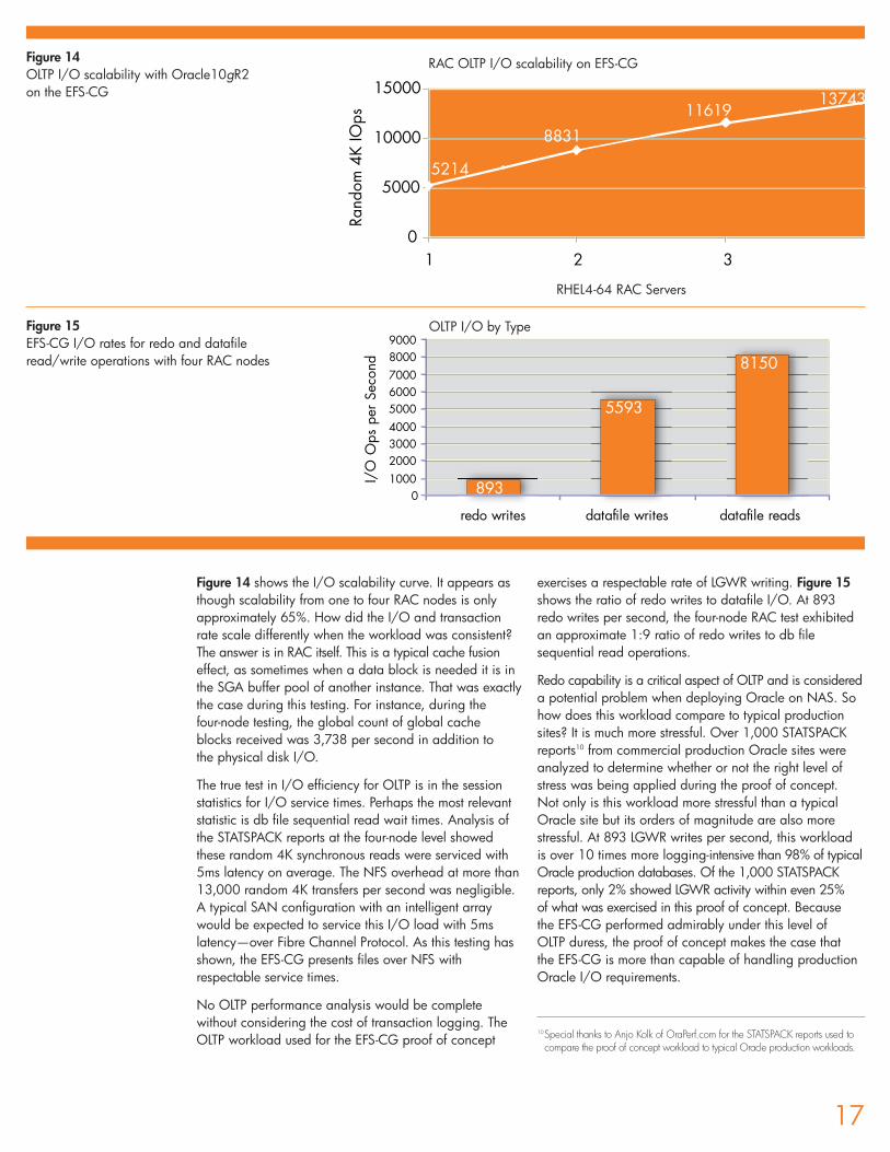
Figure 14 shows the I/O scalability curve. It appears asthough scalability from one to four RAC nodes is onlyapproximately 65%. How did the I/O and transactionrate scale differently when the workload was consistent?The answer is in RAC itself. This is a typical cache fusioneffect, as sometimes when a data block is needed it is inthe SGA buffer pool of another instance. That was exactlythe case during this testing. For instance, during the four-node testing, the global count of global cache blocks received was 3,738 per second in addition to the physical disk I/O.
The true test in I/O efficiency for OLTP is in the sessionstatistics for I/O service times. Perhaps the most relevantstatistic is db file sequential read wait times. Analysis ofthe STATSPACK reports at the four-node level showedthese random 4K synchronous reads were serviced with5ms latency on average. The NFS overhead at more than13,000 random 4K transfers per second was negligible.A typical SAN configuration with an intelligent arraywould be expected to service this I/O load with 5mslatency—over Fibre Channel Protocol. As this testing hasshown, the EFS-CG presents files over NFS withrespectable service times.
No OLTP performance analysis would be completewithout considering the cost of transaction logging. TheOLTP workload used for the EFS-CG proof of concept
exercises a respectable rate of LGWR writing. Figure 15shows the ratio of redo writes to datafile I/O. At 893redo writes per second, the four-node RAC test exhibitedan approximate 1:9 ratio of redo writes to db filesequential read operations.
Redo capability is a critical aspect of OLTP and is considereda potential problem when deploying Oracle on NAS. Sohow does this workload compare to typical productionsites? It is much more stressful. Over 1,000 STATSPACKreports10 from commercial production Oracle sites wereanalyzed to determine whether or not the right level ofstress was being applied during the proof of concept. Not only is this workload more stressful than a typicalOracle site but its orders of magnitude are also morestressful. At 893 LGWR writes per second, this workloadis over 10 times more logging-intensive than 98% of typicalOracle production databases. Of the 1,000 STATSPACKreports, only 2% showed LGWR activity within even 25% of what was exercised in this proof of concept. Because the EFS-CG performed admirably under this level of OLTP duress, the proof of concept makes the case that the EFS-CG is more than capable of handling productionOracle I/O requirements.
17
5214
8831
1161913743
0
5000
10000
15000
1 2 3
RHEL4-64 RAC Servers
Rand
om 4
K IO
ps
Figure 14 OLTP I/O scalability with Oracle10gR2 on the EFS-CG
RAC OLTP I/O scalability on EFS-CG
893
5593
8150
0100020003000400050006000700080009000
redo writes datafile writes datafile reads
I/O
Ops
per
Sec
ond
RHEL4-64 RAC Servers
OLTP I/O by TypeFigure 15EFS-CG I/O rates for redo and datafileread/write operations with four RAC nodes
10Special thanks to Anjo Kolk of OraPerf.com for the STATSPACK reports used tocompare the proof of concept workload to typical Oracle production workloads.
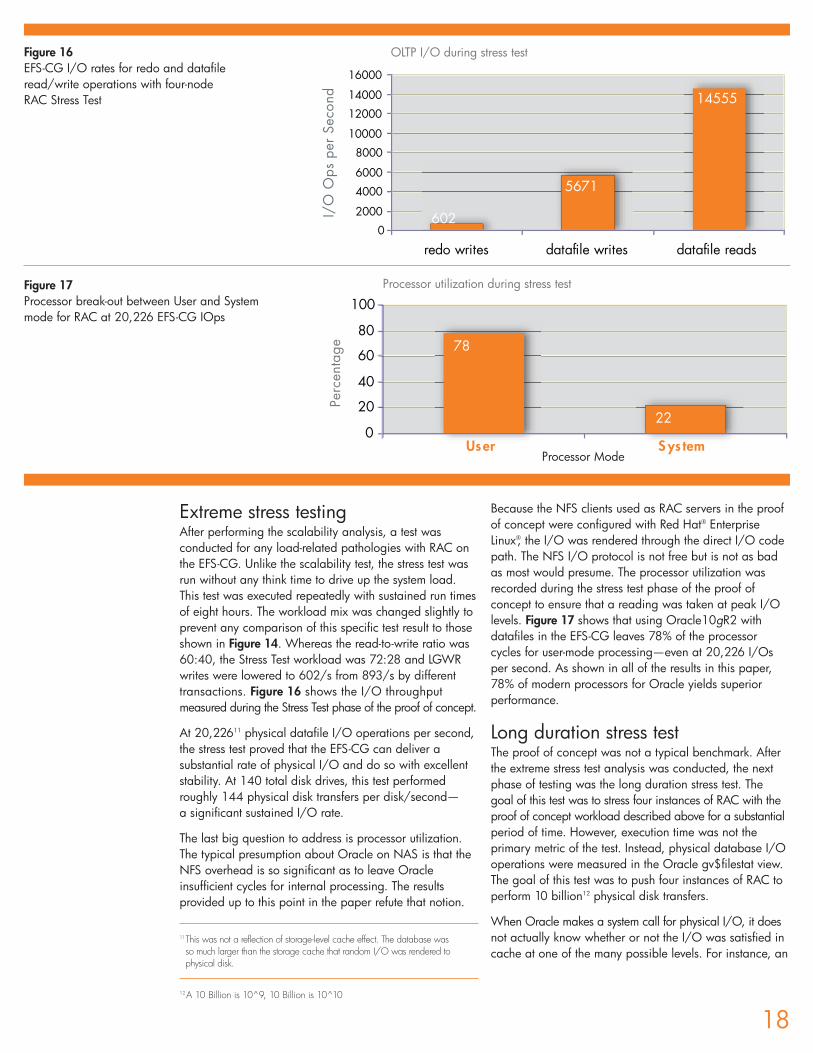
Extreme stress testingAfter performing the scalability analysis, a test wasconducted for any load-related pathologies with RAC onthe EFS-CG. Unlike the scalability test, the stress test wasrun without any think time to drive up the system load.This test was executed repeatedly with sustained run timesof eight hours. The workload mix was changed slightly toprevent any comparison of this specific test result to thoseshown in Figure 14. Whereas the read-to-write ratio was60:40, the Stress Test workload was 72:28 and LGWRwrites were lowered to 602/s from 893/s by differenttransactions. Figure 16 shows the I/O throughputmeasured during the Stress Test phase of the proof of concept.
At 20,22611 physical datafile I/O operations per second,the stress test proved that the EFS-CG can deliver asubstantial rate of physical I/O and do so with excellentstability. At 140 total disk drives, this test performedroughly 144 physical disk transfers per disk/second—a significant sustained I/O rate.
The last big question to address is processor utilization.The typical presumption about Oracle on NAS is that theNFS overhead is so significant as to leave Oracleinsufficient cycles for internal processing. The resultsprovided up to this point in the paper refute that notion.
Because the NFS clients used as RAC servers in the proofof concept were configured with Red Hat® EnterpriseLinux®, the I/O was rendered through the direct I/O codepath. The NFS I/O protocol is not free but is not as badas most would presume. The processor utilization wasrecorded during the stress test phase of the proof ofconcept to ensure that a reading was taken at peak I/Olevels. Figure 17 shows that using Oracle10gR2 withdatafiles in the EFS-CG leaves 78% of the processorcycles for user-mode processing—even at 20,226 I/Osper second. As shown in all of the results in this paper,78% of modern processors for Oracle yields superiorperformance.
Long duration stress testThe proof of concept was not a typical benchmark. Afterthe extreme stress test analysis was conducted, the nextphase of testing was the long duration stress test. The goal of this test was to stress four instances of RAC with theproof of concept workload described above for a substantialperiod of time. However, execution time was not theprimary metric of the test. Instead, physical database I/Ooperations were measured in the Oracle gv$filestat view.The goal of this test was to push four instances of RAC toperform 10 billion12 physical disk transfers.
When Oracle makes a system call for physical I/O, it doesnot actually know whether or not the I/O was satisfied incache at one of the many possible levels. For instance, an
18
78
220
20
40
60
80
100
metsySresU
Perc
enta
ge
Figure 16 EFS-CG I/O rates for redo and datafileread/write operations with four-node RAC Stress Test
602
5671
14555
0
2000
4000
6000
8000
10000
12000
14000
16000
redo writes datafile writes datafile reads
I/O
Ops
per
Sec
ond
Processor utilization during stress test
OLTP I/O during stress test
Figure 17Processor break-out between User and Systemmode for RAC at 20,226 EFS-CG IOps
Processor Mode
11This was not a reflection of storage-level cache effect. The database was so much larger than the storage cache that random I/O was rendered tophysical disk.
12A 10 Billion is 10^9, 10 Billion is 10^10
Oracle single block read (e.g., db file sequential read)might actually be satisfied with an OS-level logical I/O ifthe block is cached in the OS page cache. Conversely, ifthe downwind storage configuration has cache (e.g., aSAN intelligent storage array), the block might be cachedat that level, eliminating a physical disk transfer. Neitherof these possibilities was true during this test. The testworkload exhibits a random I/O pattern as describedabove. The main table being accessed randomly wasover 200GB and the storage array cache was only 4GB,so activity against this table alone renders the storagearray cache obsolete. Because the RAC instances wererunning on Linux servers with a 2.6 kernel, Oracle wasaccessing the files in the EFS-CG filesystem through thedirect I/O code path. Essentially, no cache existed otherthan the SGA. The physical disk transfers counted in thegv$filestat table were indeed physical disk transfers.
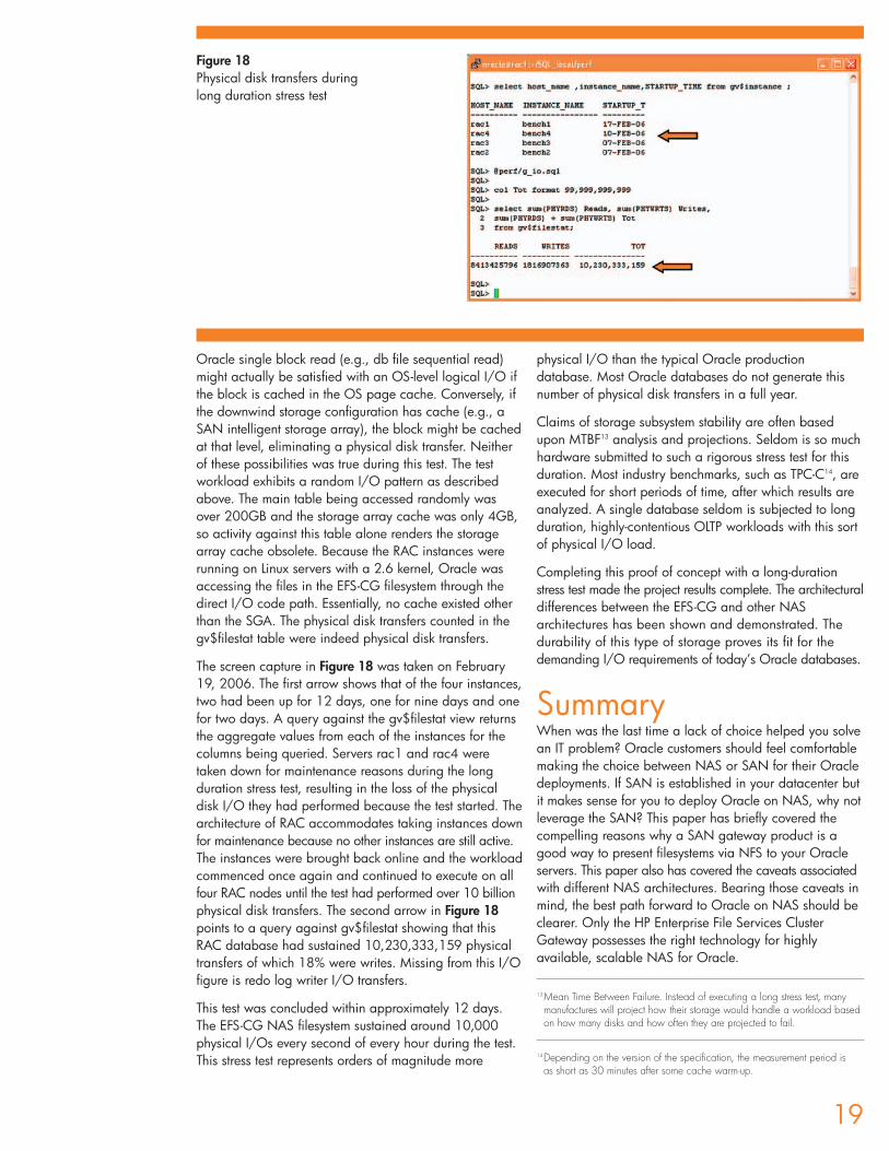
The screen capture in Figure 18 was taken on February19, 2006. The first arrow shows that of the four instances,two had been up for 12 days, one for nine days and onefor two days. A query against the gv$filestat view returnsthe aggregate values from each of the instances for thecolumns being queried. Servers rac1 and rac4 weretaken down for maintenance reasons during the longduration stress test, resulting in the loss of the physicaldisk I/O they had performed because the test started. Thearchitecture of RAC accommodates taking instances downfor maintenance because no other instances are still active.The instances were brought back online and the workloadcommenced once again and continued to execute on allfour RAC nodes until the test had performed over 10 billionphysical disk transfers. The second arrow in Figure 18points to a query against gv$filestat showing that thisRAC database had sustained 10,230,333,159 physicaltransfers of which 18% were writes. Missing from this I/Ofigure is redo log writer I/O transfers.
This test was concluded within approximately 12 days.The EFS-CG NAS filesystem sustained around 10,000physical I/Os every second of every hour during the test.This stress test represents orders of magnitude more
physical I/O than the typical Oracle productiondatabase. Most Oracle databases do not generate thisnumber of physical disk transfers in a full year.
Claims of storage subsystem stability are often basedupon MTBF13 analysis and projections. Seldom is so muchhardware submitted to such a rigorous stress test for thisduration. Most industry benchmarks, such as TPC-C14, areexecuted for short periods of time, after which results areanalyzed. A single database seldom is subjected to longduration, highly-contentious OLTP workloads with this sortof physical I/O load.
Completing this proof of concept with a long-durationstress test made the project results complete. The architecturaldifferences between the EFS-CG and other NASarchitectures has been shown and demonstrated. Thedurability of this type of storage proves its fit for thedemanding I/O requirements of today’s Oracle databases.
SummaryWhen was the last time a lack of choice helped you solvean IT problem? Oracle customers should feel comfortablemaking the choice between NAS or SAN for their Oracledeployments. If SAN is established in your datacenter butit makes sense for you to deploy Oracle on NAS, why notleverage the SAN? This paper has briefly covered thecompelling reasons why a SAN gateway product is agood way to present filesystems via NFS to your Oracleservers. This paper also has covered the caveats associatedwith different NAS architectures. Bearing those caveats inmind, the best path forward to Oracle on NAS should beclearer. Only the HP Enterprise File Services ClusterGateway possesses the right technology for highlyavailable, scalable NAS for Oracle.
19
Figure 18Physical disk transfers duringlong duration stress test
13Mean Time Between Failure. Instead of executing a long stress test, manymanufactures will project how their storage would handle a workload basedon how many disks and how often they are projected to fail.
14Depending on the version of the specification, the measurement period is as short as 30 minutes after some cache warm-up.
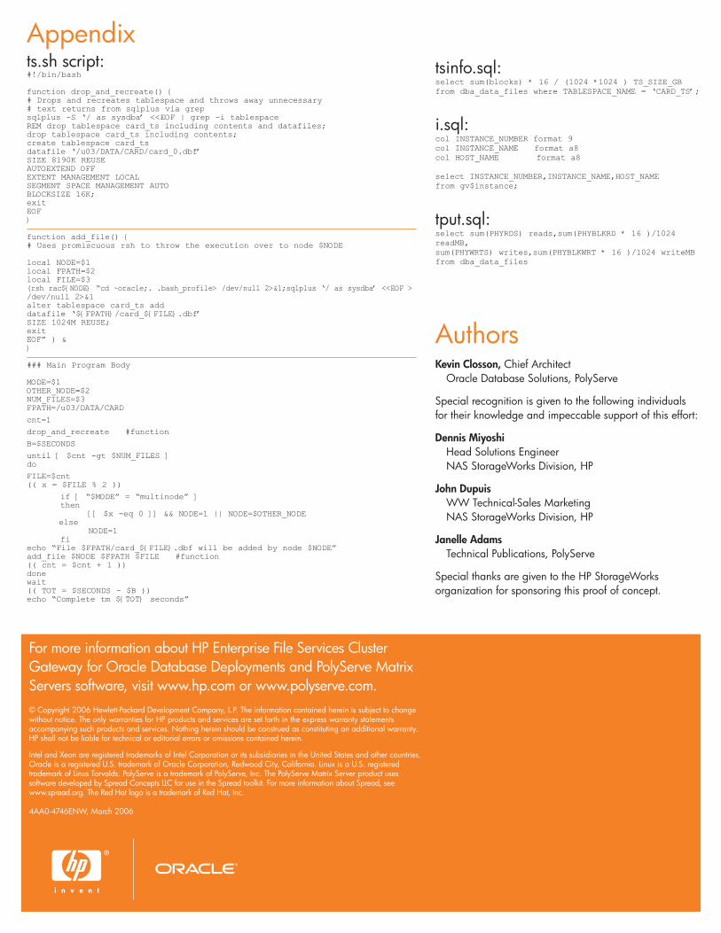
tsinfo.sql:select sum(blocks) * 16 / (1024 *1024 ) TS_SIZE_GBfrom dba_data_files where TABLESPACE_NAME = ‘CARD_TS’;
i.sql:col INSTANCE_NUMBER format 9col INSTANCE_NAME format a8col HOST_NAME format a8
select INSTANCE_NUMBER,INSTANCE_NAME,HOST_NAMEfrom gv$instance;
tput.sql:select sum(PHYRDS) reads,sum(PHYBLKRD * 16 )/1024readMB,sum(PHYWRTS) writes,sum(PHYBLKWRT * 16 )/1024 writeMBfrom dba_data_files
AuthorsKevin Closson, Chief Architect
Oracle Database Solutions, PolyServe
Special recognition is given to the following individualsfor their knowledge and impeccable support of this effort:
Dennis MiyoshiHead Solutions EngineerNAS StorageWorks Division, HP
John DupuisWW Technical-Sales MarketingNAS StorageWorks Division, HP
Janelle AdamsTechnical Publications, PolyServe
Special thanks are given to the HP StorageWorksorganization for sponsoring this proof of concept.
Appendixts.sh script:#!/bin/bash
function drop_and_recreate() {# Drops and recreates tablespace and throws away unnecessary# text returns from sqlplus via grepsqlplus -S ‘/ as sysdba’ <<EOF | grep -i tablespaceREM drop tablespace card_ts including contents and datafiles;drop tablespace card_ts including contents;create tablespace card_tsdatafile ‘/u03/DATA/CARD/card_0.dbf’SIZE 8190K REUSEAUTOEXTEND OFFEXTENT MANAGEMENT LOCALSEGMENT SPACE MANAGEMENT AUTOBLOCKSIZE 16K;exitEOF}
function add_file() {# Uses promiscuous rsh to throw the execution over to node $NODE
local NODE=$1 local FPATH=$2local FILE=$3(rsh rac${NODE} “cd ~oracle;. .bash_profile> /dev/null 2>&1;sqlplus ‘/ as sysdba’ <<EOF >/dev/null 2>&1alter tablespace card_ts adddatafile ‘${FPATH}/card_${FILE}.dbf’SIZE 1024M REUSE;exitEOF” ) &}
### Main Program Body
MODE=$1OTHER_NODE=$2NUM_FILES=$3FPATH=/u03/DATA/CARD
cnt=1
drop_and_recreate #function
B=$SECONDS
until [ $cnt -gt $NUM_FILES ]do
FILE=$cnt(( x = $FILE % 2 ))
if [ “$MODE” = “multinode” ]then
[[ $x -eq 0 ]] && NODE=1 || NODE=$OTHER_NODEelse
NODE=1fi
echo “File $FPATH/card_${FILE}.dbf will be added by node $NODE”add_file $NODE $FPATH $FILE #function(( cnt = $cnt + 1 ))donewait(( TOT = $SECONDS - $B ))echo “Complete tm ${TOT} seconds”
For more information about HP Enterprise File Services ClusterGateway for Oracle Database Deployments and PolyServe MatrixServers software, visit www.hp.com or www.polyserve.com.© Copyright 2006 Hewlett-Packard Development Company, L.P. The information contained herein is subject to changewithout notice. The only warranties for HP products and services are set forth in the express warranty statementsaccompanying such products and services. Nothing herein should be construed as constituting an additional warranty.HP shall not be liable for technical or editorial errors or omissions contained herein.
Intel and Xeon are registered trademarks of Intel Corporation or its subsidiaries in the United States and other countries.Oracle is a registered U.S. trademark of Oracle Corporation, Redwood City, California. Linux is a U.S. registeredtrademark of Linus Torvalds. PolyServe is a trademark of PolyServe, Inc. The PolyServe Matrix Server product usessoftware developed by Spread Concepts LLC for use in the Spread toolkit. For more information about Spread, seewww.spread.org. The Red Hat logo is a trademark of Red Hat, Inc.
4AA0-4746ENW, March 2006