table of contents - accuride wheel end … · hub-piloted — 10-hole, 285.75mm bolt circle ......
TRANSCRIPT


1
TABLE OF CONTENTS Pages 2-3Pages 4-5Page 7
General InformationActive Part Number IndexWheel and Rim Limited Warranty Aluminum Wheel Finishes
SECTION I Pages 8-9Pages 10-11 Page 11 Page 12 Page 13
Hub-Piloted Tubeless WheelsHub-Piloted — 10-Hole, 285.75mm Bolt CircleHub-Piloted — 8-Hole, 275mm Bolt CircleHub-Piloted — Styled Steel WheelsHub-Piloted — 10-Hole, 11¼" Bolt Circle, Special Bus ApplicationHub-Piloted — 10-Hole, 335mm Bolt Circle
SECTION II Pages 15-16 Page 17 Page 17
Stud-Piloted Tubeless & Tube-Type WheelsStud-Piloted — 10-Hole, 11¼" Bolt CircleStud-Piloted — 10-Hole, 8¾" Bolt CircleStud-Piloted — 6-Hole, 8¾" Bolt Circle
SECTION III Page 19 Page 20 Page 21
Demountable Rims, Spacer Bands and ComponentsTubeless Demountable RimsHeavy Duty Tube-Type Demountable RimsDemountable Rims Dimensions
SECTION IV Pages 23-24 Page 25
Duplex® Disc Wheels and Duplex® Demountable Rims Duplex® Disc Wheels Duplex® Demountable Rims
SECTION V Pages 27-30 Page 31
Light Truck WheelsLight Truck WheelsApplication Chart — Light Truck Wheels
SECTION VIPage 33
Bolt-Together Specialty Wheels Bolt-Together Specialty Wheels
SECTION VII Page 35Page 36Page 37Page 38Page 39Pages 40-41Pages 42-43 Page 44Page 45Page 46 Page 47Page 48Page 49Pages 50-55Page 56Page 57
General InformationWheel Guard Separator PlateRecommended Nut Torque ChartAluminum Wheel Hand Hole Size by Part NumberTypes of Accuride Rims, Rings, and Typical Disc-To-Rim Attachment LocationsAccuride Typical Product StampingHow to Identify Damaged Rims/WheelsChangeover from Conventional to Wide Base Tubeless TiresSelected Duplex® Changeover Applications 385/65R22.5 and 425/65R22.5 Tire SizeSelected Duplex® Changeover Applications to Aluminum and Driver/TrailerDual Spacing of WheelsDual Spacing of Demountable RimsChangeover from Tube-Type Tires to Tubeless TiresChart for Properly Matching Truck Tires to Rims/WheelsObsolete Part Number IndexRim/Wheel GlossaryAccuride Facilities and Production Locations
WARNING: Air pressure in an infl ated truck tire mounted on a rim/wheel creates explosive energy; this pressure can cause the tire/rim
assembly and/or components to burst apart with great force. If struck by an exploding tire or rim component, you can be seriously injured
or killed. FEDERAL OSHA REGULATIONS REQUIRE ALL EMPLOYERS TO PROVIDE TRAINING FOR ALL EMPLOYEES WHO SERVICE
SINGLE-PIECE AND MULTI-PIECE RIMS/WHEELS. THIS TRAINING SHOULD ENSURE THAT EACH EMPLOYEE DEMONSTRATES
AND MAINTAINS HIS ABILITY TO SERVICE SINGLE AND MULTI-PIECE RIMS/WHEELS. THIS KIND OF SAFETY, SERVICE, AND
MAINTENANCE INFORMATION IS CONTAINED IN THE ACCURIDE RIM/WHEEL SAFETY & SERVICE MANUAL, WHICH SHOULD
BE RETAINED BY YOU. The Accuride Rim/Wheel Safety & Service Manual and other educational, informational, and training items
are available free of charge. Please reference page 35. Please write to Literature Distribution, Accuride Corporation, 7140 Offi ce Circle,
Evansville, IN 47715 or call (800) 626-7096 to receive free copies. Outside the US call (812) 962-5000. You should not, nor should you
let your employees, service rims/wheels unless they are thoroughly trained and completely understand this safety information.
2
Part Number Size and Type Page NumberItem
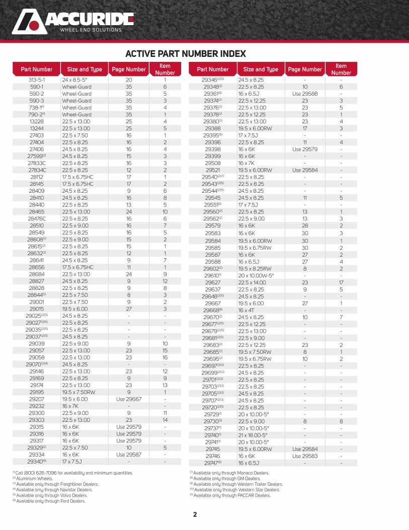
Number 313-5-1 24 x 8.5-5° 20 1590-1 Wheel-Guard 35 6590-2 Wheel-Guard 35 5590-3 Wheel-Guard 35 3738-1(1) Wheel-Guard 35 4790-2(1) Wheel-Guard 35 113228 22.5 x 13.00 25 413244 22.5 x 13.00 25 527403 22.5 x 7.50 16 127404 22.5 x 8.25 16 227406 24.5 x 8.25 16 4
27599(2) 24.5 x 8.25 15 327833C 22.5 x 8.25 16 3 27834C 22.5 x 8.25 12 2
28112 17.5 x 6.75HC 17 128145 17.5 x 6.75HC 17 228409 24.5 x 8.25 9 628410 24.5 x 8.25 16 828440 22.5 x 8.25 13 528465 22.5 x 13.00 24 1028476C 22.5 x 8.25 16 628510 22.5 x 9.00 16 728549 22.5 x 8.25 16 5
28608(2) 22.5 x 9.00 15 228615(2) 22.5 x 8.25 15 128632(2) 22.5 x 8.25 12 128641 24.5 x 8.25 9 728656 17.5 x 6.75HC 11 128684 22.5 x 13.00 24 928827 24.5 x 8.25 9 1228828 22.5 x 8.25 9 8
28844(2) 22.5 x 7.50 8 329001 22.5 x 7.50 9 229015 19.5 x 6.00 27 3
29025(2)(5) 24.5 x 8.25 - -29027(2)(5) 22.5 x 8.25 - -29035(2)(5) 22.5 x 8.25 - -29037(2)(5) 24.5 x 8.25 - -
29039 22.5 x 9.00 9 1029057 22.5 x 13.00 23 1529058 22.5 x 13.00 23 16
29070(2)(4) 24.5 x 8.25 - -29146 22.5 x 13.00 23 1229169 22.5 x 8.25 9 929174 22.5 x 13.00 23 1329195 19.5 x 7.50RW 9 129207 19.5 x 6.00 Use 29667 -29232 16 x 7K - -29300 22.5 x 9.00 9 1129303 22.5 x 13.00 23 1429315 16 x 6K Use 29579 -29316 16 x 6K Use 29579 -29317 16 x 6K Use 29579 -
29329(2) 22.5 x 7.50 10 529334 16 x 6K Use 29587 -
29340(6) 17 x 7.5J - -
Part Number Size and Type Page NumberItem
Number 29346(2)(5) 24.5 x 8.25 - -29348(2) 22.5 x 8.25 10 629361(8) 16 x 6.5J Use 29588 -29374(2) 22.5 x 12.25 23 329376(2) 22.5 x 13.00 23 529378(2) 22.5 x 12.25 23 129380(2) 22.5 x 13.00 23 429388 19.5 x 6.00RW 17 3
29395(6) 17 x 7.5J - -29396 22.5 x 8.25 11 429398 16 x 6K Use 29579 -29399 16 x 6K - -29508 16 x 7K - -29521 19.5 x 6.00RW Use 29584 -
29540(2)(7) 22.5 x 8.25 - -29543(2)(5) 22.5 x 8.25 - -29544(2)(5) 24.5 x 8.25 - -
29545 24.5 x 8.25 11 529551(6) 17 x 7.5J - -29560(2) 22.5 x 8.25 13 129562(2) 22.5 x 9.00 13 329579 16 x 6K 28 229583 16 x 6K 30 329584 19.5 x 6.00RW 30 129585 19.5 x 6.75RW 30 229587 16 x 6K 27 229588 16 x 6.5J 27 4
29602(2) 19.5 x 8.25RW 8 229610(1) 20 x 10.00W-5° - -29627 22.5 x 14.00 23 1729637 22.5 x 8.25 9 5
29648(2)(5) 24.5 x 8.25 - -29667 19.5 x 6.00 27 1
29668(8) 16 x 4T - -29670(2) 24.5 x 8.25 10 7
29677(2)(5) 22.5 x 12.25 - -29679(2)(5) 22.5 x 13.00 - -29681(2)(5) 22.5 x 9.00 - -29683(2) 22.5 x 12.25 23 229685(2) 19.5 x 7.50RW 8 129695(2) 19.5 x 6.75RW 10 2
29697(2)(3) 22.5 x 8.25 - -29699(2)(3) 24.5 x 8.25 - -29701(2)(3) 22.5 x 8.25 - -29703(2)(3) 22.5 x 8.25 - -29705(2)(3) 24.5 x 8.25 - -29707(2)(3) 24.5 x 8.25 - -29720(2)(5) 22.5 x 8.25 - -29729(1) 20 x 10.00-5° - -29730(2) 22.5 x 9.00 8 829737(1) 20 x 10.00-5° - -29740(1) 21 x 18.00-5° - -29741(1) 20 x 10.00-5° - -29745 19.5 x 6.00RW Use 29584 -29746 16 x 6K Use 29583 -
29747(6) 16 x 6.5J - -
ACTIVE PART NUMBER INDEX
(1) Call (800) 626-7096 for availability and minimum quantities. (2) Aluminum Wheels. (3) Available only through Freightliner Dealers. (4) Available only through Navistar Dealers. (5) Available only through Volvo Dealers.(6) Available only through Ford Dealers.
(7) Available only through Monaco Dealers. (8) Available only through GM Dealers.(9) Available only through Western Trailer Dealers.(10) Available only through Western Star Dealers.(11) Available only through PACCAR Dealers.

3
Part Number Size and Type Page NumberItem
Number 29748(1) 20 x 10.00-5° - -29805 22.5 x 12.25 23 929806 22.5 x 12.25 23 1029807 22.5 x 12.25 23 1129816 22.5 x 12.25 24 729818 22.5 x 13.00 24 8
29838PK 18 x 8J - -29839 19.5 x 6.00RW Use 29884 -
29841PK 17 x 7.5J - -29850(1) 20 x 10.0-5° - -29857 20 x 10.0-5° - -29875 19.5 x 6.75RW - -29883 19.5 x 6.00 RW Use 29884 -29884 19.5 x 6.00RW 29 229889 16 x 6K Use 29583 -29911 20 x 10.0-5° - -29914 20 x 10.0-5° - -29922 20 x 10.0-5° - -29923 21 x 18.0-5° - -29943 16 x 6K Use 29579 -31674 22.5 x 12.25 25 131677 22.5 x 12.25 25 231679 22.5 x 12.25 25 3
40000(2)(9) 22.5 x 8.25 - -40002(2)(9) 22.5 x 8.25 - -40004(2)(10) 22.5 x 8.25 - -40006(2)(10) 24.5 x 8.25 - -40008(2) 22.5 x 8.25 8 640012(2) 22.5 x 9.00 8 740014(2) 22.5 x 8.25 13 240018(2) 19.5 x 6.00RW 29 1
40020(2)(7) 22.5 x 8.25 - -40036(2) 22.5 x 13.00 23 640124(2)(4) 22.5 x 8.25 - -40160(2) 19.5 x 7.50RW 10 340162(2) 19.5 x 7.50RW 10 440164(2) 22.5 x 11.75 24 140166(2) 22.5 x 11.75 24 240171(2) 17.5 x 6.75 10 140176(2) 22.5 x 11.75 24 340178(2) 22.5 x 11.75 24 440180(2) 22.5 x 9.00 13 440386(2) 22.5 x 11.75 24 540394(2) 22.5 x 11.75 24 640550(2) 24.5 x 8.25 8 941016(2) 22.5 x 14.00 Use 41140 -41140(2) 22.5 x 14.00 23 741142(2) 22.5 x 14.00 23 841362(2) 24.5 x 8.25 8 541644(2) 22.5 x 8.25 8 441660(2) 22.5 x 14.00 Use 41142 -50052(1) 22.5 x 12.25 - -50082 20 x 10.00 - -
50095(8) - -50172 22.5 x 14.00 23 1850180 19.5 x 6.75RW 11 2
Part Number Size and Type Page NumberItem
Number 50194 20 x 10.00 - -
50198(8) 17 x 6.5J Use 50642 -50232 19.5 x 6.75RW 11 3
50240(8) 17 x 7.5J Use 50640 -50257 20 x 10.00 - -
50264(3) 17 x 7.5 - -50291(11) 22.5 x 8.25 - -50344(11) 22.5 x 8.25 - -50352 24 x 8.5 - -50408 22.5 x 8.25 9 350434 22.5 x 7.50 - -50487 22.5 x 8.25 9 450593 22.5 x 9.00 13 6
50640(8) 17 x 7.5 - -50642 17 x 6.5J 28 1100065 Wheel-Guard 35 2
30371225 22.5 x 7.50 19 330391225 22.5 x 8.25 19 430391245 24.5 x 8.25 19 531814175 17.5 x 8.25HC 19 231868175 17.5 x 6.75HC 19 132051225 22.5 x 8.25 19 632051245 24.5 x 8.25 19 832052225 22.5 x 9.00 19 7
ACTIVE PART NUMBER INDEX
(1) Call (800) 626-7096 for availability and minimum quantities. (2) Aluminum Wheels. (3) Available only through Freightliner Dealers. (4) Available only through Navistar Dealers. (5) Available only through Volvo Dealers.(6) Available only through Ford Dealers.
(7) Available only through Monaco Dealers. (8) Available only through GM Dealers.(9) Available only through Western Trailer Dealers.(10) Available only through Western Star Dealers.(11) Available only through PACCAR Dealers.
4
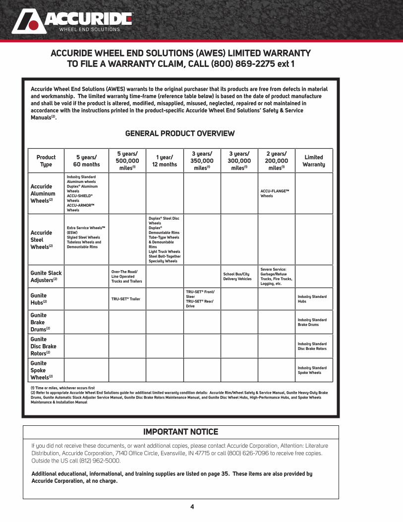
ACCURIDE WHEEL END SOLUTIONS (AWES) LIMITED WARRANTY TO FILE A WARRANTY CLAIM, CALL (800) 869-2275 ext 1
IMPORTANT NOTICE
If you did not receive these documents, or want additional copies, please contact Accuride Corporation, Attention: Literature Distribution, Accuride Corporation, 7140 Offi ce Circle, Evansville, IN 47715 or call (800) 626-7096 to receive free copies. Outside the US call (812) 962-5000.
Additional educational, informational, and training supplies are listed on page 35. These items are also provided by Accuride Corporation, at no charge.
Accuride Wheel End Solutions (AWES) warrants to the original purchaser that its products are free from defects in material and workmanship. The limited warranty time-frame (reference table below) is based on the date of product manufacture and shall be void if the product is altered, modifi ed, misapplied, misused, neglected, repaired or not maintained in accordance with the instructions printed in the product-specifi c Accuride Wheel End Solutions’ Safety & Service Manuals(2).
GENERAL PRODUCT OVERVIEW
Product Type
5 years/60 months
5 years/500,000
miles(1)
1 year/12 months
3 years/350,000
miles(1)
3 years/300,000
miles(1)
2 years/200,000
miles(1)
Limited Warranty
Accuride Aluminum Wheels(2)
Industry Standard Aluminum wheelsDuplex® Aluminum WheelsACCU-SHIELD®
WheelsACCU-ARMOR™ Wheels
ACCU-FLANGE™ Wheels
Accuride Steel Wheels(2)
Extra Service Wheels™ (ESW)Styled Steel WheelsTubeless Wheels and Demountable Rims
Duplex® Steel Disc WheelsDuplex® Demountable RimsTube-Type Wheels & Demountable RimsLight Truck WheelsSteel Bolt-Together Specialty Wheels
Gunite Slack Adjusters(2)
Over-The Road/Line Operated Trucks and Trailers
School Bus/City Delivery Vehicles
Severe Service: Garbage/Refuse Trucks, Fire Trucks, Logging, etc.
Gunite Hubs(2)
TRU-SET® Trailer
TRU-SET® Front/SteerTRU-SET® Rear/Drive
Industry Standard Hubs
Gunite Brake Drums(2)
Industry Standard Brake Drums
Gunite Disc Brake Rotors(2)
Industry Standard Disc Brake Rotors
Gunite Spoke Wheels(2)
Industry Standard Spoke Wheels
(1) Time or miles, whichever occurs fi rst(2) Refer to appropriate Accuride Wheel End Solutions guide for additional limited warranty condition details: Accuride Rim/Wheel Safety & Service Manual, Gunite Heavy-Duty Brake Drums, Gunite Automatic Slack Adjuster Service Manual, Gunite Disc Brake Rotors Maintenance Manual, and Gunite Disc Wheel Hubs, High-Performance Hubs, and Spoke Wheels Maintenance & Installation Manual
5
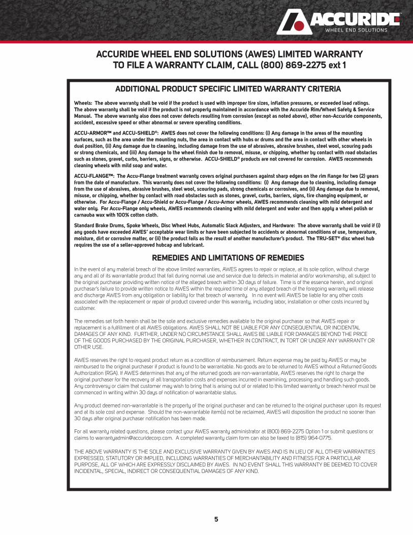
ACCURIDE WHEEL END SOLUTIONS (AWES) LIMITED WARRANTY TO FILE A WARRANTY CLAIM, CALL (800) 869-2275 ext 1
ADDITIONAL PRODUCT SPECIFIC LIMITED WARRANTY CRITERIA
Wheels: The above warranty shall be void if the product is used with improper tire sizes, infl ation pressures, or exceeded load ratings. The above warranty shall be void if the product is not properly maintained in accordance with the Accuride Rim/Wheel Safety & Service Manual. The above warranty also does not cover defects resulting from corrosion (except as noted above), other non-Accuride components, accident, excessive speed or other abnormal or severe operating conditions.
ACCU-ARMOR™ and ACCU-SHIELD®: AWES does not cover the following conditions: (i) Any damage in the areas of the mounting surfaces, such as the area under the mounting nuts, the area in contact with hubs or drums and the area in contact with other wheels in dual position, (ii) Any damage due to cleaning, including damage from the use of abrasives, abrasive brushes, steel wool, scouring pads or strong chemicals, and (iii) Any damage to the wheel fi nish due to removal, misuse, or chipping, whether by contact with road obstacles such as stones, gravel, curbs, barriers, signs, or otherwise. ACCU-SHIELD® products are not covered for corrosion. AWES recommends cleaning wheels with mild soap and water.
ACCU-FLANGE™: The Accu-Flange treatment warranty covers original purchasers against sharp edges on the rim fl ange for two (2) years from the date of manufacture. This warranty does not cover the following conditions: (i) Any damage due to cleaning, including damage from the use of abrasives, abrasive brushes, steel wool, scouring pads, strong chemicals or corrosives, and (ii) Any damage due to removal, misuse, or chipping, whether by contact with road obstacles such as stones, gravel, curbs, barriers, signs, tire changing equipment, or otherwise. For Accu-Flange / Accu-Shield or Accu-Flange / Accu-Armor wheels, AWES recommends cleaning with mild detergent and water only. For Accu-Flange only wheels, AWES recommends cleaning with mild detergent and water and then apply a wheel polish or carnauba wax with 100% cotton cloth.
Standard Brake Drums, Spoke Wheels, Disc Wheel Hubs, Automatic Slack Adjusters, and Hardware: The above warranty shall be void if (i) any goods have exceeded AWES’ acceptable wear limits or have been subjected to accidents or abnormal conditions of use, temperature, moisture, dirt or corrosive matter, or (ii) the product fails as the result of another manufacturer’s product. The TRU-SET® disc wheel hub requires the use of a seller-approved hubcap and lubricant.
REMEDIES AND LIMITATIONS OF REMEDIESIn the event of any material breach of the above limited warranties, AWES agrees to repair or replace, at its sole option, without charge any and all of its warrantable product that fail during normal use and service due to defects in material and/or workmanship, all subject to the original purchaser providing written notice of the alleged breach within 30 days of failure. Time is of the essence herein, and original purchaser’s failure to provide written notice to AWES within the required time of any alleged breach of the foregoing warranty will release and discharge AWES from any obligation or liability for that breach of warranty. In no event will AWES be liable for any other costs associated with the replacement or repair of product covered under this warranty, including labor, installation or other costs incurred by customer.
The remedies set forth herein shall be the sole and exclusive remedies available to the original purchaser so that AWES repair or replacement is a fulfi llment of all AWES obligations. AWES SHALL NOT BE LIABLE FOR ANY CONSEQUENTIAL OR INCIDENTAL DAMAGES OF ANY KIND. FURTHER, UNDER NO CIRCUMSTANCE SHALL AWES BE LIABLE FOR DAMAGES BEYOND THE PRICE OF THE GOODS PURCHASED BY THE ORIGINAL PURCHASER, WHETHER IN CONTRACT, IN TORT OR UNDER ANY WARRANTY OR OTHER USE.
AWES reserves the right to request product return as a condition of reimbursement. Return expense may be paid by AWES or may be reimbursed to the original purchaser if product is found to be warrantable. No goods are to be returned to AWES without a Returned Goods Authorization (RGA). If AWES determines that any of the returned goods are non-warrantable, AWES reserves the right to charge the original purchaser for the recovery of all transportation costs and expenses incurred in examining, processing and handling such goods. Any controversy or claim that customer may wish to bring that is arising out of or related to this limited warranty or breach hereof must be commenced in writing within 30 days of notifi cation of warrantable status.
Any product deemed non-warrantable is the property of the original purchaser and can be returned to the original purchaser upon its request and at its sole cost and expense. Should the non-warrantable item(s) not be reclaimed, AWES will disposition the product no sooner than 30 days after original purchaser notifi cation has been made.
For all warranty related questions, please contact your AWES warranty administrator at (800) 869-2275 Option 1 or submit questions or claims to [email protected]. A completed warranty claim form can also be faxed to (815) 964-0775. THE ABOVE WARRANTY IS THE SOLE AND EXCLUSIVE WARRANTY GIVEN BY AWES AND IS IN LIEU OF ALL OTHER WARRANTIES EXPRESSED, STATUTORY OR IMPLIED, INCLUDING WARRANTIES OF MERCHANTABILITY AND FITNESS FOR A PARTICULAR PURPOSE, ALL OF WHICH ARE EXPRESSLY DISCLAIMED BY AWES. IN NO EVENT SHALL THIS WARRANTY BE DEEMED TO COVER INCIDENTAL, SPECIAL, INDIRECT OR CONSEQUENTIAL DAMAGES OF ANY KIND.

6
Gen
eral
In
form
atio
nB
olt-
Toge
ther
Sp
ecia
lty
Whe
els
Ligh
t Tru
ck
Whe
els
Dup
lex
Dis
c® W
heel
s D
uple
x® D
emou
ntab
le
Rim
s
Dem
ount
able
Rim
s &
Com
pone
nts
Stud
-Pilo
ted
Tube
less
Whe
els
Hub
-Pilo
ted
Tube
less
Whe
els HUB-PILOTED
TUBELESS WHEELS

7
ALUMINUM WHEEL FINISH OPTIONS
AluminumFinish Code Aluminum Finish Name
SP Standard Polish
XP Extra Polish
AOP Traditional Outside Polish
AIP Traditional Inside Polish
ABP Traditional Both Sides Polish
C Accu-Shield® Wheels with Protective Coating
F Accu-Flange™ Protective Flange Coating
R Accu-Armor™ Finish
FC Accu-Flange™ with Accu-Shield®
RF Accu-Armor™ with Accu-Flange™
ALUMINUM FINISHES
When it comes to ensuring the durability of your aluminum wheels, you have a choice. Specify Accu-Flange™ from
Accuride to protect your aluminum-wheel investment. It’s ideal for severe-duty applications where loads are prone
to shifting, circumstances requiring frequent stops and starts, as well as gritty operating environments that accelerate
fl ange wear.
Accu-Armor™ Wheel Surface TreatmentNeed a wheel that will not only perform in the toughest environment but will always look good? Look no further than our
Accu-Armor finish. Our texturized and anodized finish will outperform in any environment, and maintain its sharp
appearance with low maintenance. Ideal for vocational applications.
Accu-Shield® Wheels with Protective CoatingDon't mess with unnecessary refi nishing costs, keep your wheels shining as if they were new with Accu-Shield®. This
low maintenance, easy cleaning coating will keep your truck looking good.
Maximize your profit and savings by switching to the lightest aluminum wheel offering in the market. Accuride
aluminum wheels allow you to increase payload, improve fuel economy, reduce tire wear, and achieve better heat
dissipation, increasing your resale value. Accuride offers one of the widest selections of wheel fi nishes in the industry.
SP and XP aluminum wheel fi nishes offer superior shine and value, while Accu-Shield®, Accu-Armor™ and Accu-
Flange™ offers a wide range of aluminum wheel fi nish options for every application
Accu-Flange™ Protective Flange Coating
For example, 41644SPFC = Standard Polish with Accu-Flange™ and Accu-Shield®. Contact your sales representative
for more information on Accuride's aluminum fi nishes.

Gen
eral
In
form
atio
nB
olt-
Toge
ther
Sp
ecia
lty
Whe
els
Ligh
t Tru
ck
Whe
els
Dup
lex
Dis
c® W
heel
s D
uple
x® D
emou
ntab
le
Rim
s
Dem
ount
able
Rim
s &
Com
pone
nts
Stud
-Pilo
ted
Tube
less
Whe
els
Hub
-Pilo
ted
Tube
less
Whe
els
8
Hub-Piloted Dual-MountingTwo-Piece Flange Nut
10-Hole, 285.75mm Bolt Circle, 220mm Bore
Item Wheel Size
Part
Number
Polish Option (Typical
Application)Wheel Offset Disc
Installed Valve
Approx. Wt. (lbs)
Maximum Load & Infl . (lbs) - (psi)
1 19.5 x 7.50RW(1)(2) 29685SP
29685AOP
29685AIP
Standard Polish
Outside (Front)
Inside (Outer Dual)
6.25" .875" TR545D 38 6700 - 125
2 19.5 x 8.25RW(1)(2) 29602SP
29602AOP
29602AIP
Standard Polish
Outside (Front)
Inside (Outer Dual)
6.63" .875" TR545D 39 7250 - 120
3 22.5 x 7.50 28844SP
28844AOP
28844AIP
Standard Polish
Outside (Front)
Inside (Outer Dual)
6.45" .935" TR545D 55 7300 - 120
4 22.5 x 8.25
2.75" Hand Hole
41644SP
41644XP
Standard Polish
Extra Polish
6.59" .875" TR545D 45 7400 - 131
5 24.5 x 8.25 41362SP
41362XP
Standard Polish
Extra Polish
6.59" .935" TR545D 54 7400 - 130
Heavy Load Applications
6 22.5 x 8.25
2.0" Hand Hole
40008SP
40008AOP
40008AIP
Standard Polish
Outside (Front)
Inside (Outer Dual)
6.59" .935" TR545D 54 8100 - 131
7 22.5 x 9.00 40012SP
40012AOP
40012AIP
Standard Polish
Outside (Front)
Inside (Outer Dual)
3.12"(3) .980" TR543E 54 10200 - 131
8 22.5 x 9.00 29730SP
29730AOP
29730AIP
29730ABP
Standard Polish
Outside (Front)
Inside (Outer Dual)
Both Sides
7.00" .980" TR545D 62 10000 - 130
9 24.5 x 8.25 40550SP
40550XP
Standard Polish
Extra Polish
6.59" .950" TR545D 60 8300-131
ACCURIDE 15° TUBELESS ALUMINUM WHEELS
(1) “RW” denotes revised well for increased brake clearance.(2) Requires special 15 x 85/8" brake package.(3) Not approved for dual application. (inset listed)

Dem
ountableR
ims &
Components
Bolt-Together
Specialty Wheels
Light Truck W
heelsD
uplex Disc
® W
heels D
uplex®
Dem
ountable R
ims
Stud-Piloted
Tubeless Wheels
Hub-P
ilotedTubeless W
heels
General
Information
9
Hub-Piloted Dual-MountingTwo-Piece Flange Nut
10-Hole, 285.75mm Bolt Circle, 220mm Bore
ACCUMOUNT EXTRA SERVICE WHEELS
Item Wheel Size
Part
NumberHand Holes
Wheel Offset Disc
Recommended Valve
Approx. Wt. (lbs)
Maximum Load & Infl . (lbs) - (psi)
1 19.5 x 7.50RW(1)(2) 29195 5 6.40" .437" TR546-36 65 6700 - 120
2 22.5 x 7.50 29001 5 6.44" .437" TR500 72 6610 - 120
3 22.5 x 8.25 50408(5)(6) 2 6.60" .437" TR572-F19 70 7400 - 120
4) 22.5 x 8.25 50487(5)(6) 5 6.60" .437" TR572-F19 68 7400 - 120
5 22.5 x 8.25 29637(5)(6) 10 6.60" .437" TR572-F19(4) 66 7400 - 120
6 24.5 x 8.25 28409 2 6.62" .437" TR573 86 7400 - 120
7 24.5 x 8.25 28641 5 6.62" .437" TR573 84 7400 - 120
Heavy Load Applications
8 22.5 x 8.25 28828 2 6.62" .472" TR573 79 8000 - 130
9 22.5 x 8.25 29169 5 6.62" .472" TR573 78 8000 - 130
10 22.5 x 9.00 29039 5 5.25"(3) .500" TR573 103 10000 - 130
11 22.5 x 9.00 29300 5 7.00" .625" TR573 108 10000 - 130
12 24.5 x 8.25 28827 2 6.62" .472" TR573 86 8000 - 120
ACCURIDE 15° TUBELESS STEEL WHEELS
(1) “RW” denotes revised well for increased brake clearance. (2) Requires special 15 x 85/8" brake package.(3) Not approved for dual application. (inset listed)(4) Valve TR572-12E may provide improved valve access to inner dual.(5) Wheel might require a different weight balance. Contact your Accuride Field Representative for additional information.(6) Refer to bulletins W2.027 and W2.020 for heavy duty application.

Gen
eral
In
form
atio
nB
olt-
Toge
ther
Sp
ecia
lty
Whe
els
Ligh
t Tru
ck
Whe
els
Dup
lex
Dis
c® W
heel
s D
uple
x® D
emou
ntab
le
Rim
s
Dem
ount
able
Rim
s &
Com
pone
nts
Stud
-Pilo
ted
Tube
less
Whe
els
Hub
-Pilo
ted
Tube
less
Whe
els
10
ACCURIDE 15° TUBELESS ALUMINUM WHEELS
(1)"RW" denotes revised well for increased brake clearance.(2) Fits only ISO Hub back-up for 8-holes, 275mm system. (3) Bolt holes are 32.87mm. ISO Standards are 26mm.
Hub-Piloted Dual-MountingTwo-Piece Flange Nut
8-Hole, 275mm Bolt Circle, 221mm Bore
Item Wheel Size
Part
Number
Polish Option (Typical
Application)Wheel Offset Disc
Installed Valve
Approx. Wt. (lbs)
Maximum Load & Infl . (lbs) - (psi)
1 17.5 x 6.75 40171SP
40171AIP
Standard Polish
Inside (Outer Dual)
5.55" .827" TR544C 30 5515 - 142
2 19.5 x 6.75RW(1)(2) 29695SP
29695AOP
29695AIP
Standard Polish
Outside (Front)
Inside (Outer Dual)
5.60" .830" TR545D 36 5000 - 125
3 19.5 x 7.50RW(1)(2) 40160SP
40160AOP
40160AIP
40160ABP
Standard Polish
Outside (Front)
Inside (Outer Dual)
Both Sides
6.25" .875" TR545D 39 6700 - 131
4 19.5 x 7.50RW(1)(2)(3) 40162SP
40162AOP
40162AIP
40162ABP
Standard Polish
Outside (Front)
Inside (Outer Dual)
Both Sides
6.25" .875" TR545D 39 6700 - 120
5 22.5 x 7.50 29329SP
29329AOP
29329AIP
29329ABP
Standard Polish
Outside (Front)
Inside (Outer Dual)
Both Sides
6.45" .935" TR545D 55 7200 - 120
6 22.5 x 8.25 29348SP
29348AOP
29348AIP
29348ABP
Standard Polish
Outside (Front)
Inside (Outer Dual)
Both Sides
6.59" .935" TR545D 55 7300 - 120
7 24.5 x 8.25 29670SP
29670ABP
Standard Polish
Both Sides
6.59" .935" TR545D 57 7300 - 120
Dem
ountableR
ims &
Components
Bolt-Together
Specialty Wheels
Light Truck W
heelsD
uplex Disc
® W
heels D
uplex®
Dem
ountable R
ims
Stud-Piloted
Tubeless Wheels
Hub-P
ilotedTubeless W
heels
General
Information
11
Hub-Piloted Dual-MountingTwo-Piece Flange Nut
8-Hole, 275mm Bolt Circle, 221mm Bore
Item Wheel Size
Part
NumberHand Holes
Wheel Offset Disc
Recommended Valve
Approx. Wt. (lbs)
Maximum Load & Infl . (lbs) - (psi)
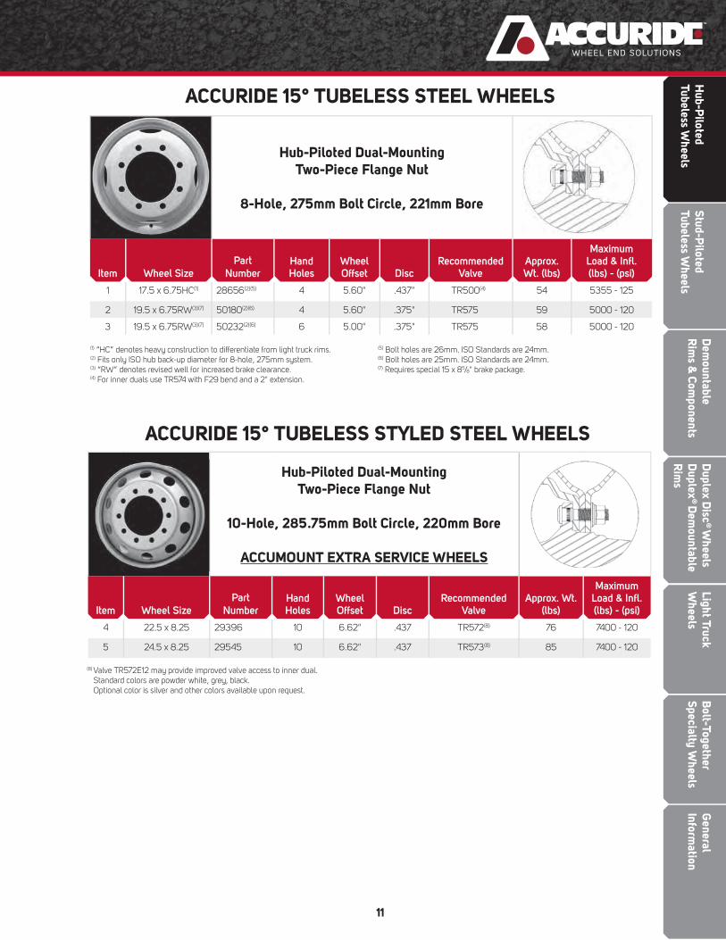
1 17.5 x 6.75HC(1) 28656(2)(5) 4 5.60" .437" TR500(4) 54 5355 - 125
2 19.5 x 6.75RW(3)(7) 50180(2)(6) 4 5.60" .375" TR575 59 5000 - 120
3 19.5 x 6.75RW(3)(7) 50232(2)(6) 6 5.00" .375" TR575 58 5000 - 120
ACCURIDE 15° TUBELESS STEEL WHEELS
(1) “HC” denotes heavy construction to differentiate from light truck rims.(2) Fits only ISO hub back-up diameter for 8-hole, 275mm system.(3) “RW” denotes revised well for increased brake clearance.(4) For inner duals use TR574 with F29 bend and a 2" extension.
(5) Bolt holes are 26mm. ISO Standards are 24mm.(6) Bolt holes are 25mm. ISO Standards are 24mm. (7) Requires special 15 x 85/8" brake package.
Hub-Piloted Dual-MountingTwo-Piece Flange Nut
10-Hole, 285.75mm Bolt Circle, 220mm Bore
ACCUMOUNT EXTRA SERVICE WHEELS
Item Wheel Size
Part
NumberHand Holes
Wheel Offset Disc
Recommended Valve
Approx. Wt. (lbs)
Maximum Load & Infl . (lbs) - (psi)
4 22.5 x 8.25 29396 10 6.62" .437 TR572(8) 76 7400 - 120
5 24.5 x 8.25 29545 10 6.62" .437 TR573(8) 85 7400 - 120
ACCURIDE 15° TUBELESS STYLED STEEL WHEELS
(8) Valve TR572E12 may provide improved valve access to inner dual.Standard colors are powder white, grey, black.Optional color is silver and other colors available upon request.

Gen
eral
In
form
atio
nB
olt-
Toge
ther
Sp
ecia
lty
Whe
els
Ligh
t Tru
ck
Whe
els
Dup
lex
Dis
c® W
heel
s D
uple
x® D
emou
ntab
le
Rim
s
Dem
ount
able
Rim
s &
Com
pone
nts
Stud
-Pilo
ted
Tube
less
Whe
els
Hub
-Pilo
ted
Tube
less
Whe
els
12
Hub-Piloted Dual-Mounting
Two-Piece Flange Nut
10-Hole, 11¼" Bolt Circle, 8.67" Bore
Special Bus Application with 1.22" Bolt Holes
EXTRA SERVICE WHEELS
Item Wheel Size
Part
NumberHand Holes
Wheel Offset Disc
Recommended Valve
Approx. Wt. (lbs)
Maximum Load & Infl . (lbs) - (psi)
2 22.5 x 8.25 27834C(1)(2) 5 6.62" .437" TR572 76 7400 - 120
ACCURIDE 15° TUBELESS STEEL WHEEL
(1) Check clearance. May not fi t some older bus applications.(2) “C” suffi x denotes balanced wheel.
Hub-Piloted Dual-Mounting
Two-Piece Flange Nut
10-Hole, 11¼" Bolt Circle, 8.67" Bore
Special Bus Application with 1.22" Bolt Holes
Item Wheel Size
Part
Number
Polish Option (Typical
Application)Wheel Offset Disc
Installed Valve
Approx. Wt. (lbs)
Maximum Load & Infl . (lbs) - (psi)
1 22.5 x 8.25 28632SP
28632XP
Standard Polish
Extra Polish
6.59" .860" TR545D 54 7300 - 120
ACCURIDE 15° TUBELESS ALUMINUM WHEEL
Dem
ountableR
ims &
Components
Bolt-Together
Specialty Wheels
Light Truck W
heelsD
uplex Disc
® W
heels D
uplex®
Dem
ountable R
ims
Stud-Piloted
Tubeless Wheels
Hub-P
ilotedTubeless W
heels
General
Information
13
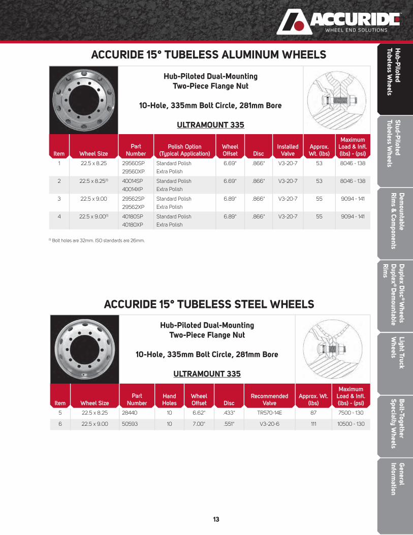
Hub-Piloted Dual-MountingTwo-Piece Flange Nut
10-Hole, 335mm Bolt Circle, 281mm Bore
ULTRAMOUNT 335
Item Wheel Size
Part
NumberHand Holes
Wheel Offset Disc
Recommended Valve
Approx. Wt. (lbs)
Maximum Load & Infl . (lbs) - (psi)
5 22.5 x 8.25 28440 10 6.62" .433" TR570-14E 87 7500 - 130
6 22.5 x 9.00 50593 10 7.00" .551" V3-20-6 111 10500 - 130
ACCURIDE 15° TUBELESS STEEL WHEELS
(1) Bolt holes are 32mm. ISO standards are 26mm.
Hub-Piloted Dual-MountingTwo-Piece Flange Nut
10-Hole, 335mm Bolt Circle, 281mm Bore
ULTRAMOUNT 335
Item Wheel Size
Part
NumberPolish Option
(Typical Application)Wheel Offset Disc
Installed Valve
Approx. Wt. (lbs)
MaximumLoad & Infl .(lbs) - (psi)
1 22.5 x 8.25 29560SP
29560XP
Standard Polish
Extra Polish
6.69" .866" V3-20-7 53 8046 - 138
2 22.5 x 8.25(1) 40014SP
40014XP
Standard Polish
Extra Polish
6.69" .866" V3-20-7 53 8046 - 138
3 22.5 x 9.00 29562SP
29562XP
Standard Polish
Extra Polish
6.89" .866" V3-20-7 55 9094 - 141
4 22.5 x 9.00(1) 40180SP
40180XP
Standard Polish
Extra Polish
6.89" .866" V3-20-7 55 9094 - 141
ACCURIDE 15° TUBELESS ALUMINUM WHEELS

STUD-PILOTEDTUBELESS WHEELS
Gen
eral
In
form
atio
nB
olt-
Toge
ther
Sp
ecia
lty
Whe
els
Ligh
t Tru
ck
Whe
els
Dup
lex
Dis
c® W
heel
s D
uple
x® D
emou
ntab
le
Rim
s
Dem
ount
able
Rim
s &
Com
pone
nts
Hub
-Pilo
ted
Tube
less
Whe
els
Stud
-Pilo
ted
Tube
less
Whe
els
Dem
ountableR
ims &
Components
Bolt-Together
Specialty Wheels
Light Truck W
heelsD
uplex Disc
® W
heels D
uplex®
Dem
ountable R
ims
Stud-Piloted
Tubeless Wheels
Hub-P
ilotedTubeless W
heels
General
Information
15
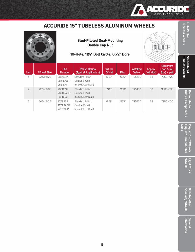
Stud-Piloted Dual-MountingDouble Cap Nut
10-Hole, 11¼" Bolt Circle, 8.72" Bore
Item Wheel Size
Part
NumberPolish Option
(Typical Application)Wheel Offset Disc
Installed Valve
Approx. Wt. (lbs)
MaximumLoad & Infl .(lbs) - (psi)
1 22.5 x 8.25 28615SP
28615AOP
28615AIP
Standard Polish
Outside (Front)
Inside (Outer Dual)
6.59" .935" TR545D 54 7250 - 120
2 22.5 x 9.00 28608SP
28608AOP
28608AIP
Standard Polish
Outside (Front)
Inside (Outer Dual)
7.00" .980" TR545D 60 9000 - 130
3 24.5 x 8.25 27599SP
27599AOP
27599AIP
Standard Polish
Outside (Front)
Inside (Outer Dual)
6.59" .935" TR545D 62 7200 - 120
ACCURIDE 15° TUBELESS ALUMINUM WHEELS
Gen
eral
In
form
atio
nB
olt-
Toge
ther
Sp
ecia
lty
Whe
els
Ligh
t Tru
ck
Whe
els
Dup
lex
Dis
c® W
heel
s D
uple
x® D
emou
ntab
le
Rim
s
Dem
ount
able
Rim
s &
Com
pone
nts
Stud
-Pilo
ted
Tube
less
Whe
els
Hub
-Pilo
ted
Tube
less
Whe
els
16
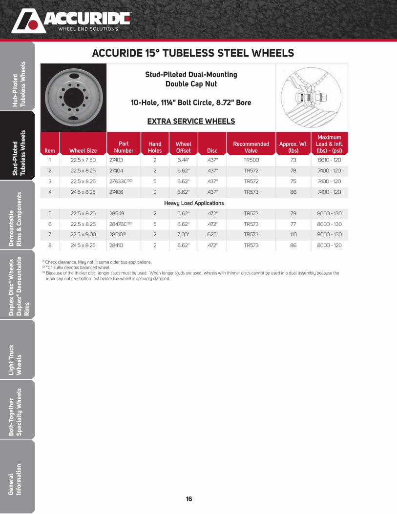
Stud-Piloted Dual-MountingDouble Cap Nut
10-Hole, 11¼" Bolt Circle, 8.72" Bore
EXTRA SERVICE WHEELS
Item Wheel Size
Part
NumberHand Holes
Wheel Offset Disc
Recommended Valve
Approx. Wt. (lbs)
Maximum Load & Infl . (lbs) - (psi)
1 22.5 x 7.50 27403 2 6.44" .437" TR500 73 6610 - 120
2 22.5 x 8.25 27404 2 6.62" .437" TR572 78 7400 - 120
3 22.5 x 8.25 27833C(1)(2) 5 6.62" .437" TR572 75 7400 - 120
4 24.5 x 8.25 27406 2 6.62" .437" TR573 86 7400 - 120
Heavy Load Applications
5 22.5 x 8.25 28549 2 6.62" .472" TR573 79 8000 - 130
6 22.5 x 8.25 28476C(1)(2) 5 6.62" .472" TR573 77 8000 - 130
7 22.5 x 9.00 28510(3) 2 7.00" .625" TR573 110 9000 - 130
8 24.5 x 8.25 28410 2 6.62" .472" TR573 86 8000 - 120
ACCURIDE 15° TUBELESS STEEL WHEELS
(1) Check clearance. May not fi t some older bus applications.(2) “C” suffi x denotes balanced wheel.(3) Because of the thicker disc, longer studs must be used. When longer studs are used, wheels with thinner discs cannot be used in a dual assembly because the
inner cap nut can bottom out before the wheel is securely clamped.
Dem
ountableR
ims &
Components
Bolt-Together
Specialty Wheels
Light Truck W
heelsD
uplex Disc
® W
heels D
uplex®
Dem
ountable R
ims
Stud-Piloted
Tubeless Wheels
Hub-P
ilotedTubeless W
heels
General
Information
17
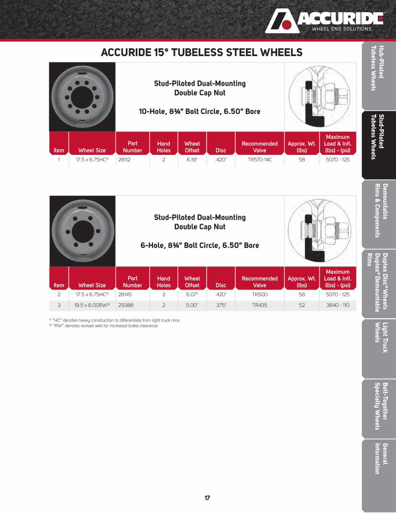
Stud-Piloted Dual-MountingDouble Cap Nut
10-Hole, 8¾" Bolt Circle, 6.50" Bore
Item Wheel Size
Part
NumberHand Holes
Wheel Offset Disc
Recommended Valve
Approx. Wt. (lbs)
Maximum Load & Infl . (lbs) - (psi)
1 17.5 x 6.75HC(1) 28112 2 6.19" .420" TR570-14C 58 5070 - 125
Stud-Piloted Dual-MountingDouble Cap Nut
6-Hole, 8¾" Bolt Circle, 6.50" Bore
Item Wheel Size
Part
NumberHand Holes
Wheel Offset Disc
Recommended Valve
Approx. Wt. (lbs)
Maximum Load & Infl . (lbs) - (psi)
2 17.5 x 6.75HC(1) 28145 2 6.07" .420" TR500 58 5070 - 125
3 19.5 x 6.00RW(2) 29388 2 5.00" .375" TR435 52 3640 - 110
ACCURIDE 15° TUBELESS STEEL WHEELS
(1) “HC” denotes heavy construction to differentiate from light truck rims. (2) “RW” denotes revised well for increased brake clearance.

Gen
eral
In
form
atio
nB
olt-
Toge
ther
Sp
ecia
lty
Whe
els
Ligh
t Tru
ck
Whe
els
Dup
lex
Dis
c® W
heel
s D
uple
x® D
emou
ntab
le
Rim
s
Stud
-Pilo
ted
Tube
less
Whe
els
DEMOUNTABLE RIMSAND COMPONENTSH
ub-P
ilote
dTu
bele
ss W
heel
sD
emou
ntab
leR
ims
& C
ompo
nent
s

Dem
ountableR
ims &
Components
Bolt-Together
Specialty Wheels
Light Truck W
heelsD
uplex Disc
® W
heels D
uplex®
Dem
ountable R
ims
Stud-Piloted
Tubeless Wheels
Hub-P
ilotedTubeless W
heels
General
Information
19
EXTRA SERVICE RIMS
Item Rim Size Part NumberRim
OffsetRecommended
ValveApprox. Wt. (lbs)
Maximum Load & Infl . (lbs) - (psi)
1 17.5 x 6.75HC(1) 31868175 3.90" TR572 46 4805 – 125
2 17.5 x 8.25HC(1) 31814175 4.75" TR573 55 6040 – 130
3 22.5 x 7.50 30371225 4.26" TR572 64 6610 – 120
4 22.5 x 8.25 30391225 4.75" TR573 68 7300 – 120
5 24.5 x 8.25 30391245 4.75" TR573 74 7300 – 120
Heavy Load Applications
6 22.5 x 8.25 32051225(2) 4.75" TR573 69 8000 – 120
7 22.5 x 9.00 32052225(2) 5.00" TR574 87 10000 – 130
8 24.5 x 8.25 32051245(2) 4.75" TR573 76 8000 – 120
Dual SpacingsAll dimensions in inches.
(See pages 47 & 49 for additional information)
RimWidthSize
RimType
Rim
Offset
Dual Spacing WithSpacer Band Width
33/8" 35/8" 4" 41/4"
7.5 FL, 5° 4.75" 12.9 13.1 13.5 13.8
8.0 5° 5.00" 13.4 13.6 14.0 14.2
8.5(3) 5° 5.30" 14.6 14.8
Spacer Bands for Tubeless Demountable Rims
Rim Diameter
Use Spacer Band Size
17.5" 15"
22.5" 20"
24.5" 22"
ACCURIDE 15° TUBELESS DEMOUNTABLE RIMS
(1) “HC” denotes heavy construction to differentiate from light truck rims.(2) Requires a six spoke cast spoke wheel to carry indicated load rating.
(3) 8.5 tube-type rims require M type spacer bands to fi t smaller diameter cast spoke wheels (see "E" dimension on page 21)

Gen
eral
In
form
atio
nB
olt-
Toge
ther
Sp
ecia
lty
Whe
els
Ligh
t Tru
ck
Whe
els
Dup
lex
Dis
c® W
heel
s D
uple
x® D
emou
ntab
le
Rim
s
Dem
ount
able
Rim
s &
Com
pone
nts
Stud
-Pilo
ted
Tube
less
Whe
els
Hub
-Pilo
ted
Tube
less
Whe
els
20
Rim Size & Type
Rim Base
Part No.(1)(2)
Side Ring Lock Ring
Item Markings/Size & Type Part No.(1) Markings/Size & Type Part No.(1)
1 24 x 8.5 – 5°(3) 313D51X 24 x 8.5 – 5° 313D5SR 24 x 8.5 – 5° 313D5LR
5° Radial Commander® 3-Piece Rim
• 5° bead seats on both sides provide maximum support under entire width of tire beads.
• Continuous base and side ring minimize tire bead chafi ng.
Item Rim Size & Type Part Number(1) Approx. Wt. (lbs)Maximum Load & Infl .
(lbs) - (psi)
1 24 x 8.5 – 5° (3) 313-5-1 118 8900 – 120
HEAVY DUTY TUBE-TYPE DEMOUNTABLE RIMS
Available Educational, Informational, and Training Itemsfor Heavy Duty Tube-Type Demountable Rims
SAFETY AND SERVICE MANUALSSafety/Service Manuals - EnglishSafety/Service Manuals - SpanishSafety/Service Manuals - French
CHARTAccuride Rim & Ring Matching Wall Chart
VIDEO (DVD)“Servicing Single and Multi-Piece Wheels”
RIM ASSEMBLY
COMPONENTS
WARNING: Air pressure in an infl ated truck tire mounted on a rim/wheel creates explosive energy; this pressure can cause the tire/rim
assembly and/or components to burst apart with great force. If struck by an exploding tire or rim component, you can be seriously injured
or killed. FEDERAL OSHA REGULATIONS REQUIRE ALL EMPLOYERS TO PROVIDE TRAINING FOR ALL EMPLOYEES WHO SERVICE
SINGLE-PIECE AND MULTI-PIECE RIMS/WHEELS. THIS TRAINING SHOULD ENSURE THAT EACH EMPLOYEE DEMONSTRATES
AND MAINTAINS HIS ABILITY TO SERVICE SINGLE AND MULTI-PIECE RIMS/WHEELS. THIS KIND OF SAFETY, SERVICE, AND
MAINTENANCE INFORMATION IS CONTAINED IN THE ACCURIDE RIM/WHEEL SAFETY & SERVICE MANUAL, WHICH SHOULD BE
RETAINED BY YOU. The Accuride Rim/Wheel Safety & Service Manual and other educational, informational, and training items are
available free of charge. Please write to Literature Distribution, Accuride Corporation, 7140 Offi ce Circle, Evansville, IN 47715 or call (800)
626-7096 to receive free copies. Outside the US call (812) 962-5000. You should not, nor should you let your employees, service rims/
wheels unless they are thoroughly trained and completely understand this safety information.
(1) Product has liquid topcoat over epoxy black E-coat.(2) “X” suffi x on part number indicates rim only (side ring and lock ring are excluded).(3) 8.5 tube-type rims require "M" type spacer bands to fi t smaller diameter cast spoke wheels (see "E" dimension on page 21).

Dem
ountableR
ims &
Components
Bolt-Together
Specialty Wheels
Light Truck W
heelsD
uplex Disc
® W
heels D
uplex®
Dem
ountable R
ims
Stud-Piloted
Tubeless Wheels
Hub-P
ilotedTubeless W
heels
General
Information
21
DIMENSIONS FOR TUBE-TYPE RIMS BY PART NUMBER(All dimensions in inches)
PartNumber
Size
A B C D E F GDia. Width Rim Offset
313-5-1(1) 24 8.5 5.30 23.372 .314 .750 1.75 22.422(1) 2.000 5.25
(1) 8.5 tube-type rims require "M" type spacer bands to fi t smaller diameter cast spoke wheels.
MAXIMUM CASTSPOKE WHEEL DIAMETER

Gen
eral
In
form
atio
nB
olt-
Toge
ther
Sp
ecia
lty
Whe
els
Ligh
t Tru
ck
Whe
els
Dem
ount
able
Rim
s &
Com
pone
nts
Stud
-Pilo
ted
Tube
less
Whe
els
DUPLEX® DISC WHEELS ANDDUPLEX® DEMOUNTABLE RIMS
Dup
lex
Dis
c® W
heel
s D
uple
x® D
emou
ntab
le
Rim
s
Hub
-Pilo
ted
Tube
less
Whe
els
Dem
ountableR
ims &
Components
Bolt-Together
Specialty Wheels
Light Truck W
heelsD
uplex Disc
® W
heels D
uplex®
Dem
ountable R
ims
Stud-Piloted
Tubeless Wheels
Hub-P
ilotedTubeless W
heels
General
Information
23
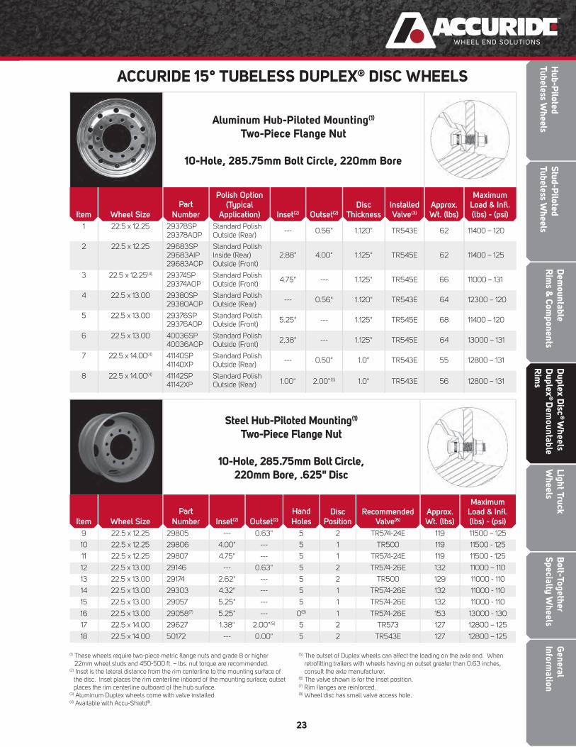
Aluminum Hub-Piloted Mounting(1)
Two-Piece Flange Nut
10-Hole, 285.75mm Bolt Circle, 220mm Bore
Item Wheel Size
Part
Number
Polish Option(Typical
Application) Inset(2) Outset(2)
DiscThickness
InstalledValve(3)
Approx. Wt. (lbs)
Maximum Load & Infl .(lbs) - (psi)
1 22.5 x 12.25 29378SP29378AOP
Standard PolishOutside (Rear) --- 0.56" 1.120" TR543E 62 11400 – 120
2 22.5 x 12.25 29683SP29683AIP29683AOP
Standard PolishInside (Rear)Outside (Front)
2.88" 4.00" 1.125" TR545E 62 11400 – 125
3 22.5 x 12.25(4) 29374SP29374AOP
Standard PolishOutside (Front) 4.75" --- 1.125" TR545E 66 11000 – 131
4 22.5 x 13.00 29380SP29380AOP
Standard PolishOutside (Rear) --- 0.56" 1.120" TR543E 64 12300 – 120
5 22.5 x 13.00 29376SP29376AOP
Standard PolishOutside (Front) 5.25" --- 1.125" TR545E 68 11400 – 120
6 22.5 x 13.00 40036SP40036AOP
Standard PolishOutside (Front) 2.38" --- 1.125" TR545E 64 13000 – 131
7 22.5 x 14.00(4) 41140SP41140XP
Standard PolishOutside (Rear) --- 0.50" 1.0" TR543E 55 12800 – 131
8 22.5 x 14.00(4) 41142SP41142XP
Standard PolishOutside (Rear) 1.00" 2.00"(5) 1.0" TR543E 56 12800 – 131
Steel Hub-Piloted Mounting(1)
Two-Piece Flange Nut
10-Hole, 285.75mm Bolt Circle, 220mm Bore, .625" Disc
Item Wheel Size
Part
Number Inset(2) Outset(2)
Hand
HolesDisc
PositionRecommended
Valve(6)
Approx. Wt. (lbs)
Maximum Load & Infl .(lbs) - (psi)
9 22.5 x 12.25 29805 --- 0.63" 5 2 TR574-24E 119 11500 – 125
10 22.5 x 12.25 29806 4.00" --- 5 1 TR500 119 11500 - 125
11 22.5 x 12.25 29807 4.75" --- 5 1 TR574-24E 119 11500 - 125
12 22.5 x 13.00 29146 --- 0.63" 5 2 TR574-26E 132 11000 – 110
13 22.5 x 13.00 29174 2.62" --- 5 2 TR500 129 11000 - 110
14 22.5 x 13.00 29303 4.32" --- 5 1 TR574-26E 132 11000 - 110
15 22.5 x 13.00 29057 5.25" --- 5 1 TR574-26E 132 11000 - 110
16 22.5 x 13.00 29058(7) 5.25" --- 0(8) 1 TR574-26E 153 13000 - 130
17 22.5 x 14.00 29627 1.38" 2.00"(5) 5 2 TR573 127 12800 – 125
18 22.5 x 14.00 50172 --- 0.00" 5 2 TR543E 127 12800 – 125
ACCURIDE 15° TUBELESS DUPLEX® DISC WHEELS
(1) These wheels require two-piece metric fl ange nuts and grade 8 or higher 22mm wheel studs and 450-500 ft. – lbs. nut torque are recommended.
(2) Inset is the lateral distance from the rim centerline to the mounting surface of the disc. Inset places the rim centerline inboard of the mounting surface; outset places the rim centerline outboard of the hub surface.
(3) Aluminum Duplex wheels come with valve installed.(4) Available with Accu-Shield®.
(5) The outset of Duplex wheels can affect the loading on the axle end. When retrofi tting trailers with wheels having an outset greater than 0.63 inches, consult the axle manufacturer.
(6) The valve shown is for the inset position.(7) Rim fl anges are reinforced.(8) Wheel disc has small valve access hole.

Gen
eral
In
form
atio
nB
olt-
Toge
ther
Sp
ecia
lty
Whe
els
Ligh
t Tru
ck
Whe
els
Dem
ount
able
Rim
s &
Com
pone
nts
Stud
-Pilo
ted
Tube
less
Whe
els
Dup
lex
Dis
c® W
heel
s D
uple
x® D
emou
ntab
le
Rim
s
Hub
-Pilo
ted
Tube
less
Whe
els
24
Aluminum Hub-Piloted MountingTwo-Piece Flange Nut
10-Hole, 335mm Bolt Circle, 281mm Bore
ULTRAMOUNT 335
Item Wheel Size
Part
NumberPolish Option Outset
(mm)
Inset
(mm)
BoltHole(mm)
Approx. Wt. (kg/
lbs)
MaximumLoad
(kg/lbs)
MaximumInfl .
(bar/psi/kPa)
1 22.5 x 11.75 40164SP40164AOP
Standard PolishOutside (Front)
148 120 26 26.1 / 57.5 4500 / 9921 9.5 / 138 / 952
2 22.5 x 11.75 40166SP40166AOP
Standard PolishOutside (Rear)
25 0 26 23 / 50 4500 / 9921 9.5 / 138 / 952
3 22.5 x 11.75 40176SP40176AOP
Standard PolishOutside (Front)
148 120 32 25.9 / 57.0 4500 / 9921 9.5 / 138 / 952
4 22.5 x 11.75 40178SP40178AOP
Standard PolishOutside (Rear)
25 0 32 23 / 50 4500 / 9921 9.5 / 138 / 952
5 22.5 x 11.75 40386SP40386AOP
Standard PolishOutside (Front)
164.5 135 32 27.8 / 61.3 4500 / 9921 9.5 / 138 / 952
6 22.5 x 11.75 40394SP40394AOP
Standard PolishOutside (Front)
164.5 135 26 28.0 / 61.8 4500 / 9921 9.5 / 138 / 952
ACCURIDE 15° TUBELESS DUPLEX® DISC WHEELS
Steel Stud-Piloted Mounting(1)
Outer Cap Nut
10-Hole, 11¼" Bolt Circle, 8.72" Bore, .625" Disc
Item Wheel Size
Part
Number Inset(3) Outset(3)
HandHoles
DiscPosition
(see pg. 25)
RecommendedValve(2)
Approx.Wt. (lbs)
MaximumLoad & Infl .(lbs) – (psi)
7 22.5 x 12.25 29816 4.75" --- 2 1 TR574-26E 129 10000 - 105(6)
8 22.5 x 13.00 29818 --- 0.63" 2 2 TR574-26E 132 10000 – 105
9 22.5 x 13.00 28684 5.25" --- 0(4) 3 TR501(5) 135 10250 - 110
(1) These wheels use standard cap nuts with 7⁄8" (.875") spherical radius. (2) The valve shown is for the inset position.(3) Inset is defi ned as the lateral distance from the rim centerline to the mounting
surface of the disc. Inset places the rim centerline inboard of the mounting surface; outset places the rim centerline outboard of the hub surface.
(4) Wheel disc has small valve access hole.(5) Wheel has two valve holes. Plug unused valve hole with Dill VS#902 or
Schrader#345 plug.(6) Wheel may be used at 9370 Ibs -120 psi with 385/65R 22.5 LR J tires.(7) The wheel must only be installed in the inset position because bolt chamfers are only on one side of the disc.
(8) These wheels require Heavy Duty (HD) outer cap nuts with a 3 3⁄16" spherical radius. Standard cap nuts have a 7⁄8" (.875") spherical radius.
Heavy Duty (HD) Steel Stud-Piloted Mounting(8) Heavy Duty Outer Cap Nut
10-Hole, 13 3/16" Heavy Duty Bolt Circle, 10.69" Bore, .625" Disc
Item Wheel Size
Part
Number Inset(3) Outset(3)(7)
Hand Holes
Disc Position
(see pg. 25)
Recommended Valve (2)
Approx. Wt. (lbs)
Maximum Load & Infl . (lbs) – (psi)
10 22.5 x 13.00 28465 6.12" --- 0(4) 3 TR570 133 10210 - 110
Dem
ountableR
ims &
Components
Bolt-Together
Specialty Wheels
Light Truck W
heelsD
uplex Disc
® W
heels D
uplex®
Dem
ountable R
ims
Stud-Piloted
Tubeless Wheels
Hub-P
ilotedTubeless W
heels
General
Information
25
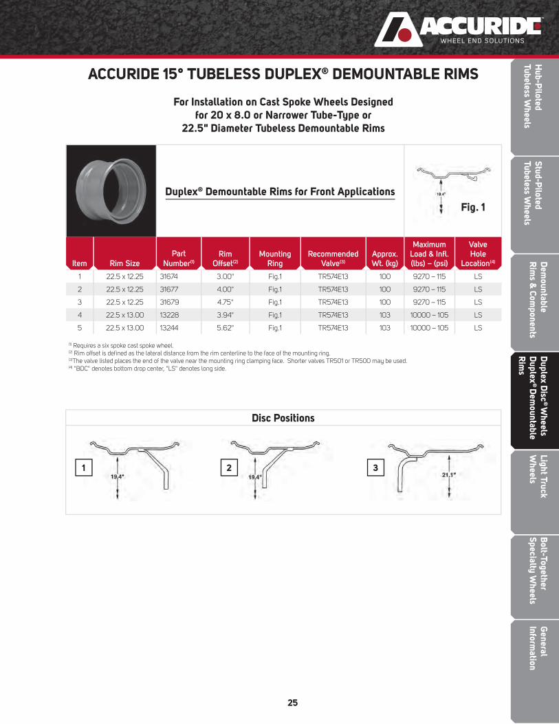
Duplex® Demountable Rims for Front Applications
Item Rim Size
Part
Number(1)
RimOffset(2)
MountingRing
RecommendedValve(3)
Approx. Wt. (kg)
MaximumLoad & Infl .(lbs) – (psi)
ValveHole
Location(4)
1 22.5 x 12.25 31674 3.00" Fig.1 TR574E13 100 9270 – 115 LS
2 22.5 x 12.25 31677 4.00" Fig.1 TR574E13 100 9270 – 115 LS
3 22.5 x 12.25 31679 4.75" Fig.1 TR574E13 100 9270 – 115 LS
4 22.5 x 13.00 13228 3.94" Fig.1 TR574E13 103 10000 – 105 LS
5 22.5 x 13.00 13244 5.62" Fig.1 TR574E13 103 10000 – 105 LS
ACCURIDE 15° TUBELESS DUPLEX® DEMOUNTABLE RIMS
For Installation on Cast Spoke Wheels Designedfor 20 x 8.0 or Narrower Tube-Type or
22.5" Diameter Tubeless Demountable Rims
Disc Positions
1 2 3
(1) Requires a six spoke cast spoke wheel. (2) Rim offset is defi ned as the lateral distance from the rim centerline to the face of the mounting ring.(3)The valve listed places the end of the valve near the mounting ring clamping face. Shorter valves TR501 or TR500 may be used.(4) "BDC" denotes bottom drop center, "LS" denotes long side.
Fig. 1

LIGHT TRUCK WHEELS
Gen
eral
In
form
atio
nB
olt-
Toge
ther
Sp
ecia
lty
Whe
els
Dup
lex
Dis
c® W
heel
s D
uple
x® D
emou
ntab
le
Rim
s
Dem
ount
able
Rim
s &
Com
pone
nts
Stud
-Pilo
ted
Tube
less
Whe
els
Hub
-Pilo
ted
Tube
less
Whe
els
Ligh
t Tru
ck
Whe
els

Dem
ountableR
ims &
Components
Bolt-Together
Specialty Wheels
Light Truck W
heelsD
uplex Disc
® W
heels D
uplex®
Dem
ountable R
ims
Stud-Piloted
Tubeless Wheels
Hub-P
ilotedTubeless W
heels
General
Information
27
Hub-Piloted Dual-MountingUse Clamping Plate w/90° Cone Nuts
10-Hole, 7¼" Bolt Circle, 5.25" Bore(P-300 Chevrolet or GMC Typical)
Item Wheel Size
Rim
Type
Part
NumberHandHoles
Wheel Offset Disc
Valve
Hole
Dia.Recommended
ValveApprox. Wt. (lbs)
MaximumLoad & Infl .(lbs) - (psi)
1 19.5 x 6.00 15° Tbls 29667 5 5.08" .375" .625" TR500 48 3000 – 95
Hub-Piloted Dual-MountingUse Clamping Plate w/90° Cone Nuts
8-Hole, 6½" Bolt Circle, 4.56" Bore(3/4 , 1 Ton, Chevrolet or GMC Typical)
Item Wheel Size
Rim
Type
Part
NumberHandHoles
Wheel Offset Disc
Valve
Hole
Dia.Recommended
ValveApprox. Wt. (lbs)
MaximumLoad & Infl .(lbs) - (psi)
2 16 x 6K 5° DC 29587 4 5.00" .308" .453" TR600HP 35 2440 – 80
3 19.5 x 6.00 15° Tbls 29015 4 5.00" .296" .625" TR573 46 2540 – 80
Hub-Piloted Dual-MountingUse Only GM Swiveling Lug Nut(1)
8-Hole, 6½" Bolt Circle, 4.60" Bore(3/4 , 1 Ton, Chevrolet or GMC Typical)
Item Wheel Size
Rim
Type
Part
NumberHandHoles
Wheel Offset Disc
Valve
Hole
Dia.Recommended
ValveApprox. Wt. (lbs)
MaximumLoad & Infl .(lbs) - (psi)
4 16 x 6.5J 5° DC 29588 4 5.04" .308" .453" TR600HP 34 2440 – 80
LIGHT TRUCK WHEELS
Wheel SizeWheel
Part Number Replaces Part Number
Clamping Plate
General Motors P/N
16 x 6K 29587 27756, 27994, 28177, 28374, 28603(2), 28623(2), 29334(2) 472536
19.5 x 6.00 29015 27774 472536
19.5 x 6.00 29667 29207 349071
(1) The GM P/N for the M14-1.5 swiveling lug nut is 9591924. This type of nut is also called a two-piece fl ange nut or cone locking nut.(2) This wheel has a .453" valve hole and requires an HP600 series valve. 27756, 27994, 28177, and 28374 have a .625" valve hole and require an appropriate valve. Reference the Tire and Rim Association Book for applicable valve.
CLAMPING PLATE TABLE

Gen
eral
In
form
atio
nB
olt-
Toge
ther
Sp
ecia
lty
Whe
els
Ligh
t Tru
ck
Whe
els
Dup
lex
Dis
c® W
heel
s D
uple
x® D
emou
ntab
le
Rim
s
Dem
ount
able
Rim
s &
Com
pone
nts
Stud
-Pilo
ted
Tube
less
Whe
els
Hub
-Pilo
ted
Tube
less
Whe
els
28
LIGHT TRUCK WHEELS
Hub-Piloted Dual-MountingUse Only Ford Swiveling Lug Nut(1)
8-Hole, 6½" Bolt Circle, 4.88" Bore(Ford 3/4 & 1 Ton Typical)
Item Wheel Size
Rim
Type
Part
NumberHandHoles
Wheel Offset Disc
Valve
Hole
Dia.Recommended
ValveApprox. Wt. (lbs)
MaximumLoad & Infl .(lbs) - (psi)
2 16 x 16K 5° DC 29579 8 5.15" .308" .453" TR600HP 35 2500 – 80
(1) The Ford P/N for the 9/16-18 swiveling lug nut is 391223. This type of nut is also called a two-piece fl ange nut or a cone locking nut.
Hub-Piloted Dual-MountingUse Only GM Swiveling Lug Nut(1)
8-Hole, 210mm Bolt Circle, 154.3mm Bore(3/4 , 1 Ton, Chevrolet or GMC Typical)
Item Wheel Size
Rim
Type
Part
NumberHandHoles
Wheel Offset Disc
Valve
Hole
Dia.Recommended
ValveApprox. Wt. (lbs)
MaximumLoad & Infl .(lbs) - (psi)
1 17 x 6.5J. 5° DC 50642 5 137mm .330" .453" TR600 41 3000-80

Dem
ountableR
ims &
Components
Bolt-Together
Specialty Wheels
Light Truck W
heelsD
uplex Disc
® W
heels D
uplex®
Dem
ountable R
ims
Stud-Piloted
Tubeless Wheels
Hub-P
ilotedTubeless W
heels
General
Information
29
LIGHT TRUCK WHEELS
Hub-Piloted Dual-MountingUse Only Ford Swiveling Lug Nut(2)
10-Hole, 225mm Bolt Circle, 170.10mm Bore
Item Wheel Size
Rim
Type
Part
NumberHandHoles
Wheel Offset Disc
Valve
Hole
Dia.Recommended
ValveApprox. Wt. (lbs)
MaximumLoad & Infl .(lbs) - (psi)
2 19.5 x 6.00RW(2) 15° Tbls 29884 5 5.35" .375" .453" TR416S 52 4000 – 115
(1) “RW” denotes revised well for increased brake clearance(2) The Ford P/N for the M14 x 2.0 swiveling lug nut is N811599. This type of nut is also called a two-piece fl ange nut or a cone locking nut.
Aluminum Light Truck WheelHub Piloted Dual Mounting
Two-Piece Flange Nut
10-Hole, 225mm Bolt Circle, 170.10mm Bore
Item Wheel Size Part NumberPolish Option
(Typical Application)Wheel Offset Disc
Installed Valve
Approx. Wt. (lbs)
MaximumLoad & Infl .(lbs) - (psi)
1 19.5 x 6.00RW(1) 40018SP
40018AOP
40018AIP
Standard Polish
Outside (Front)
Inside (Outer Dual)
5.35" .598" TR545D 32 4000 - 110

Gen
eral
In
form
atio
nB
olt-
Toge
ther
Sp
ecia
lty
Whe
els
Ligh
t Tru
ck
Whe
els
Dup
lex
Dis
c® W
heel
s D
uple
x® D
emou
ntab
le
Rim
s
Dem
ount
able
Rim
s &
Com
pone
nts
Stud
-Pilo
ted
Tube
less
Whe
els
Hub
-Pilo
ted
Tube
less
Whe
els
30
LIGHT TRUCK WHEELS
Hub-Piloted Dual-MountingUse Only Ford Swiveling Lug Nut(1)
8-Hole, 225mm Bolt Circle, 170.10mm Bore(Ford F-Super Duty Typical)
Item Wheel Size
Rim
Type
Part
NumberHandHoles
Wheel Offset Disc
Valve
Hole
Dia.Recommended
Valve
Approx. Wt. (lbs)
MaximumLoad & Infl .(lbs) - (psi)
1 19.5 x 6.00RW(2) 15° Tbls 29584 5 5.35" .375" .453" VS 902 K 51 3750 – 115
2 19.5 x 6.75RW(2) 15° Tbls 29585 5 5.50" .375" .625" TR500 59 4000 – 115
(1) The Ford P/N for the M14 x 2.0 swiveling lug nut is N811599. This type of nut is also called a two-piece fl ange nut or a cone locking nut.(2) “RW” denotes revised well for increased brake clearance.
Hub-Piloted Dual-MountingUse Only Ford Swiveling Lug Nut(1)
8-Hole, 170mm Bolt Circle, 125.10mm Bore(Ford F-Super Duty Typical)
Item Wheel Size
Rim
Type
Part
NumberHandHoles
Wheel Offset Disc
Valve
Hole
Dia.Recommended
Valve
Approx. Wt. (lbs)
MaximumLoad & Infl .(lbs) - (psi)
3 16 x 6K 5° DC 29583 4 5.35" .330" .453" TR600HP 37 2600 – 80
Dem
ountableR
ims &
Components
Bolt-Together
Specialty Wheels
Light Truck W
heelsD
uplex Disc
® W
heels D
uplex®
Dem
ountable R
ims
Stud-Piloted
Tubeless Wheels
Hub-P
ilotedTubeless W
heels
General
Information
31
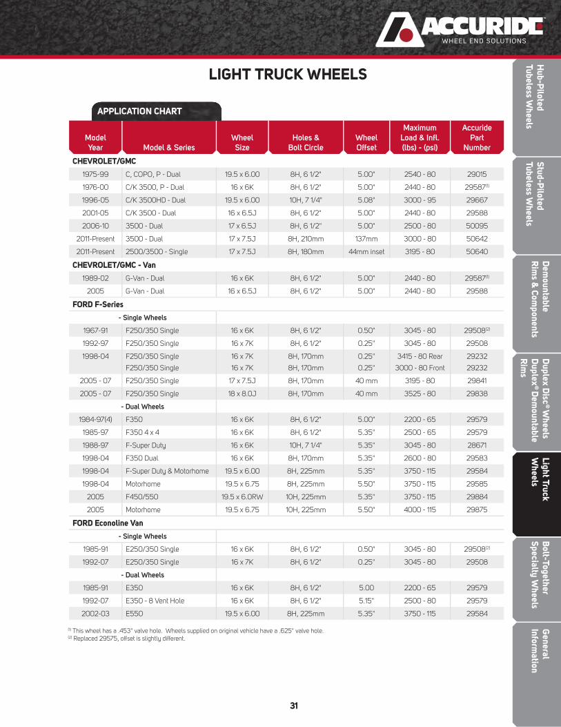
Model
Year Model & Series
Wheel
Size
Holes &
Bolt Circle
Wheel
Offset
Maximum
Load & Infl .
(lbs) - (psi)
Accuride
Part
Number
CHEVROLET/GMC
1975-99 C, COPO, P - Dual 19.5 x 6.00 8H, 6 1/2" 5.00" 2540 - 80 29015
1976-00 C/K 3500, P - Dual 16 x 6K 8H, 6 1/2" 5.00" 2440 - 80 29587(1)
1996-05 C/K 3500HD - Dual 19.5 x 6.00 10H, 7 1/4" 5.08" 3000 - 95 29667
2001-05 C/K 3500 - Dual 16 x 6.5J 8H, 6 1/2" 5.00" 2440 - 80 29588
2006-10 3500 - Dual 17 x 6.5J 8H, 6 1/2" 5.00" 2500 - 80 50095
2011-Present 3500 - Dual 17 x 7.5J 8H, 210mm 137mm 3000 - 80 50642
2011-Present 2500/3500 - Single 17 x 7.5J 8H, 180mm 44mm inset 3195 - 80 50640
CHEVROLET/GMC - Van
1989-02 G-Van - Dual 16 x 6K 8H, 6 1/2" 5.00" 2440 - 80 29587(1)
2005 G-Van - Dual 16 x 6.5J 8H, 6 1/2" 5.00" 2440 - 80 29588
FORD F-Series
- Single Wheels
1967-91 F250/350 Single 16 x 6K 8H, 6 1/2" 0.50" 3045 - 80 29508(2)
1992-97 F250/350 Single 16 x 7K 8H, 6 1/2" 0.25" 3045 - 80 29508
1998-04 F250/350 Single
F250/350 Single
16 x 7K
16 x 7K
8H, 170mm
8H, 170mm
0.25"
0.25"
3415 - 80 Rear
3000 - 80 Front
29232
29232
2005 - 07 F250/350 Single 17 x 7.5J 8H, 170mm 40 mm 3195 - 80 29841
2005 - 07 F250/350 Single 18 x 8.0J 8H, 170mm 40 mm 3525 - 80 29838
- Dual Wheels
1984-97(4) F350 16 x 6K 8H, 6 1/2" 5.00" 2200 - 65 29579
1985-97 F350 4 x 4 16 x 6K 8H, 6 1/2" 5.35" 2500 - 65 29579
1988-97 F-Super Duty 16 x 6K 10H, 7 1/4" 5.35" 3045 - 80 28671
1998-04 F350 Dual 16 x 6K 8H, 170mm 5.35" 2600 - 80 29583
1998-04 F-Super Duty & Motorhome 19.5 x 6.00 8H, 225mm 5.35" 3750 - 115 29584
1998-04 Motorhome 19.5 x 6.75 8H, 225mm 5.50" 3750 - 115 29585
2005 F450/550 19.5 x 6.0RW 10H, 225mm 5.35" 3750 - 115 29884
2005 Motorhome 19.5 x 6.75 10H, 225mm 5.50" 4000 - 115 29875
FORD Econoline Van
- Single Wheels
1985-91 E250/350 Single 16 x 6K 8H, 6 1/2" 0.50" 3045 - 80 29508(2)
1992-07 E250/350 Single 16 x 7K 8H, 6 1/2" 0.25" 3045 - 80 29508
- Dual Wheels
1985-91 E350 16 x 6K 8H, 6 1/2" 5.00 2200 - 65 29579
1992-07 E350 - 8 Vent Hole 16 x 6K 8H, 6 1/2" 5.15" 2500 - 80 29579
2002-03 E550 19.5 x 6.00 8H, 225mm 5.35" 3750 - 115 29584
(1) This wheel has a .453" valve hole. Wheels supplied on original vehicle have a .625" valve hole.(2) Replaced 29575, offset is slightly different.
LIGHT TRUCK WHEELS
APPLICATION CHART
Gen
eral
In
form
atio
nLi
ght T
ruck
W
heel
sD
uple
x D
isc®
Whe
els
Dup
lex®
Dem
ount
able
R
ims
Dem
ount
able
Rim
s &
Com
pone
nts
Stud
-Pilo
ted
Tube
less
Whe
els
BOLT-TOGETHERSPECIALTY WHEELSH
ub-P
ilote
dTu
bele
ss W
heel
sB
olt-
Toge
ther
Sp
ecia
lty
Whe
els
Dem
ountableR
ims &
Components
Bolt-Together
Specialty Wheels
Light Truck W
heelsD
uplex Disc
® W
heels D
uplex®
Dem
ountable R
ims
Stud-Piloted
Tubeless Wheels
Hub-P
ilotedTubeless W
heels
General
Information
33
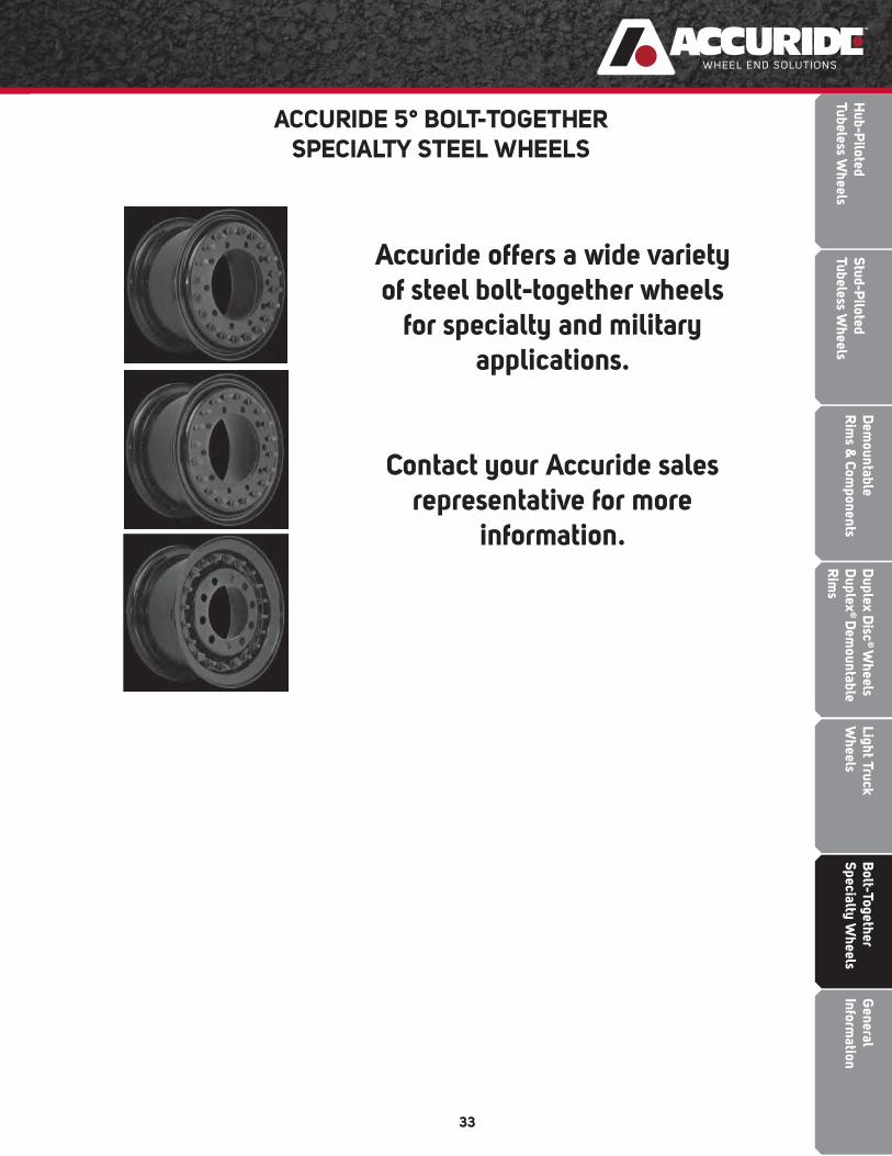
Accuride offers a wide variety of steel bolt-together wheels
for specialty and military applications.
Contact your Accuride sales representative for more
information.
ACCURIDE 5° BOLT-TOGETHERSPECIALTY STEEL WHEELS
Bol
t-To
geth
er
Spec
ialt
y W
heel
sLi
ght T
ruck
W
heel
sD
uple
x D
isc®
Whe
els
Dup
lex®
Dem
ount
able
R
ims
Dem
ount
able
Rim
s &
Com
pone
nts
Stud
-Pilo
ted
Tube
less
Whe
els
GENERAL INFORMATIONH
ub-P
ilote
dTu
bele
ss W
heel
sG
ener
al
Info
rmat
ion

Dem
ountableR
ims &
Components
Bolt-Together
Specialty Wheels
Light Truck W
heelsD
uplex Disc
® W
heels D
uplex®
Dem
ountable R
ims
Stud-Piloted
Tubeless Wheels
Hub-P
ilotedTubeless W
heels
General
Information
35
WHEEL-GUARD® SEPARATOR PLATE
590-1 590-3
The Wheel-Guard Separator Plate is approximately .040" thick. It is placed between the hub or drum and the wheel, and/or between two wheels in dual applications. Not to be installed between hub and brake drum. The Wheel-Guard is recommended in severe applications where corrosion and/or wear have been identifi ed. Both aluminum and steel wheels can benefi t from use of the Wheel-Guard. Care must be exercised in centering the separator plate prior to torquing, and stud length must be checked as each plate is approximately .040" thick.
Item Part Number Bolt Circle Application
1 790-2 8 hole - 275mm hub-piloted; 22mm diameter studs
2 100065 10 hole - 225mm hub-piloted; 14mm diameter studs
3 590-3 10 hole - 285.75mm hub-piloted; 22mm diameter studs
4 738-1 10 hole - 335mm hub-piloted; ISO European Mount, 22mm diameter studs
5 590-2 10 hole - 11¼" stud-piloted; 3/4" diameter studs
6 590-1 10 hole - 11¼" stud-piloted; 7/8" and 11/8" diameter studs
Available Accuride Educational, Informational, and Training ItemsITEM DESCRIPTION ITEM DESCRIPTION
CATALOGSWheel and Rim Catalog - English
SAFETY AND SERVICE MANUALSSafety/Service Manuals - EnglishSafety/Service Manuals - SpanishSafety/Service Manuals - French
VIDEO (DVD)“Servicing Single and Multi-Piece Wheels” (BLUE)“Servicing and Maintaining Disc Wheels” (GREEN)“Accu-Forge Aluminum Wheels - The BrightPerformers” (PURPLE)“Servicing and Maintaining Demountable Rims”(ORANGE)
CHARTSAccuride Rim & Ring Matching Wall ChartHub-Piloted/Stud-Piloted Wheel Mounting System Identifi cation ChartWheel Out of Service Wall ChartWRIS Nut Torque Chart
OTHERHub-Piloted, 8-Hole, 275mm Bolt Circle chassis labelHub-Piloted, 10-Hole, 285.75mm Bolt Circlechassis labelNut and Chamfer Gage Kit (P/N 5400)Accuride touch up spray paint can (Grey #5411, white #5412, black #5413)Aluminum Wheel Flange Wear Gage #5401KAccuride Touch Up Pens (Grey 5416, White 5417, Black 5415)
The Accuride Rim/Wheel Safety & Service Manual and other educational, informational, and training items are available. Please write to Literature Distribution, Accuride Corporation, 7140 Offi ce Circle, Evansville IN, 47715 or call (800) 626-7096 to receive free copies. Outside the US call (812) 962-5000.

Gen
eral
In
form
atio
nB
olt-
Toge
ther
Sp
ecia
lty
Whe
els
Ligh
t Tru
ck
Whe
els
Dup
lex
Dis
c® W
heel
s D
uple
x® D
emou
ntab
le
Rim
s
Dem
ount
able
Rim
s &
Com
pone
nts
Stud
-Pilo
ted
Tube
less
Whe
els
Hub
-Pilo
ted
Tube
less
Whe
els
36
RECOMMENDED NUT TORQUEMounting Thread Size Torque ft-lbs. Nut Type
LIGHT TRUCK
10-Hole, 7.25" Hub-Piloted (Ford) (5.47" Bore) 9/16 - 18 125 - 165 Two piece fl ange
10-Hole, 7.25" Hub-Piloted (GM)(5.25" Bore) - With Clamping Plate
5/8 - 18 171 - 17990o cone(1) With Clamping Plate
8-Hole, 6.50" I.O.C. (Ford)9/16 - 18 175 - 200 90o cone
5/8 - 18 175 - 200 90o cone
8-Hole, 210mm, Hub-Piloted (GM) M14 x 1.5 136 - 144 Two piece fl ange
8-Hole, 6.50" Hub-Piloted (Ford)(4.88" Bore)
9/16 - 18 125 - 165 Two piece fl ange
5/8 - 18 130 - 170 Two piece fl ange
8-Hole, 6.50" Stud-Piloted (Ford)(4.88" Bore) - Single Wheel
9/16 - 18 130 - 150 60o cone
8-Hole, 6.50" Hub-Piloted (GM) M14 x 1.5 110 - 120 Two piece fl ange
8-Hole, 6.50" Hub-Piloted (GM)(4.56" Bore) - With Clamping Plate
9/16 - 18 136 - 144 90o cone(1)
M14 x 1.5 136 - 144 With Clamping Plate
8-Hole, 6.50" Hub-Piloted (GM)(4.60" Bore)
M14 x 1.5 136 - 144 Two piece fl ange
8-Hole, 170mm, Hub-Piloted (Ford)(125.10mm Bore)
M14 x 2.0 150 - 160 Two piece fl ange
8-Hole, 225mm Hub-Piloted (Ford)(170.10mm Bore)
M14 x 2.0 150 - 160 Two piece fl ange
6-Hole, 8.75" Stud-Piloted3/4 - 16 450 - 500 .875" spherical radius
1 - 1/8 - 16 450 - 500 .875" spherical radius
6-Hole, 222.25mm Stud-Piloted Japanese .866" Nut Type
M20 x 1.5 325 - 400 .866" spherical radius
MEDIUM/HEAVY TRUCK, TRAILER AND BUS
10-Hole, 13 3/16" HD Stud-Piloted15/16 - 12 750 - 900 1.187" spherical radius
1 - 5/16 - 12 750 - 900 1.187" spherical radius
10-Hole, 335mm Hub-Piloted M22 x1.5 450 - 500 Two piece fl ange
10-Hole, 11 1/4" Stud-Piloted3/4 - 16 450 - 500 .875" spherical radius
1 - 1/8 - 16 450 - 500 .875" spherical radius
10-Hole, 11 1/4" Hub-Piloted(Bus Mount)
3/4 - 16 300 - 350 Two piece fl ange
7/8 - 14 350 - 400 Two piece fl ange
10-Hole, 285.75mm Hub-Piloted M22 x1.5 450 - 500 Two piece fl ange
10-Hole, 8.75" Hub-Piloted 11/16 - 16 300 - 400 One piece fl anged
10-Hole, 8.75" Stud-Piloted3/4 - 16 450 - 500 .875" spherical radius
1 - 1/8 - 16 450 - 500 .875" spherical radius
10-Hole, 200mm Hub-Piloted (Ford) M14 x 2.0 150 - 160 Two piece fl ange
10-Hole, 225mm Hub-Piloted (Ford) M14 x 2.0 150 - 160 Two piece fl ange
8-Hole, 285mm Stud-Piloted Japanese Check truck manufacturer for torque details
8-Hole, 275mm Hub-PilotedM20 x1.5 280 - 330 Two piece fl ange
M22 x1.5 450 - 500 Two niece fl ange
Demountable Rims 3/4 - 10 200 - 260 Flat nut
(1) These nuts can only be used with a clamping plate. Do not use 90° cone nuts against the disc face.Note: Hub, stud and spoke wheel manufacturers may have different torque requirements. Consult Accuride Field Engineering at (800) 869-2275 if torque recommendations confl ict. Refer to Accuride's Rim/Wheel Safety Service Manual for information on torque and nut tightening sequence.
Dem
ountableR
ims &
Components
Bolt-Together
Specialty Wheels
Light Truck W
heelsD
uplex Disc
® W
heels D
uplex®
Dem
ountable R
ims
Stud-Piloted
Tubeless Wheels
Hub-P
ilotedTubeless W
heels
General
Information
37
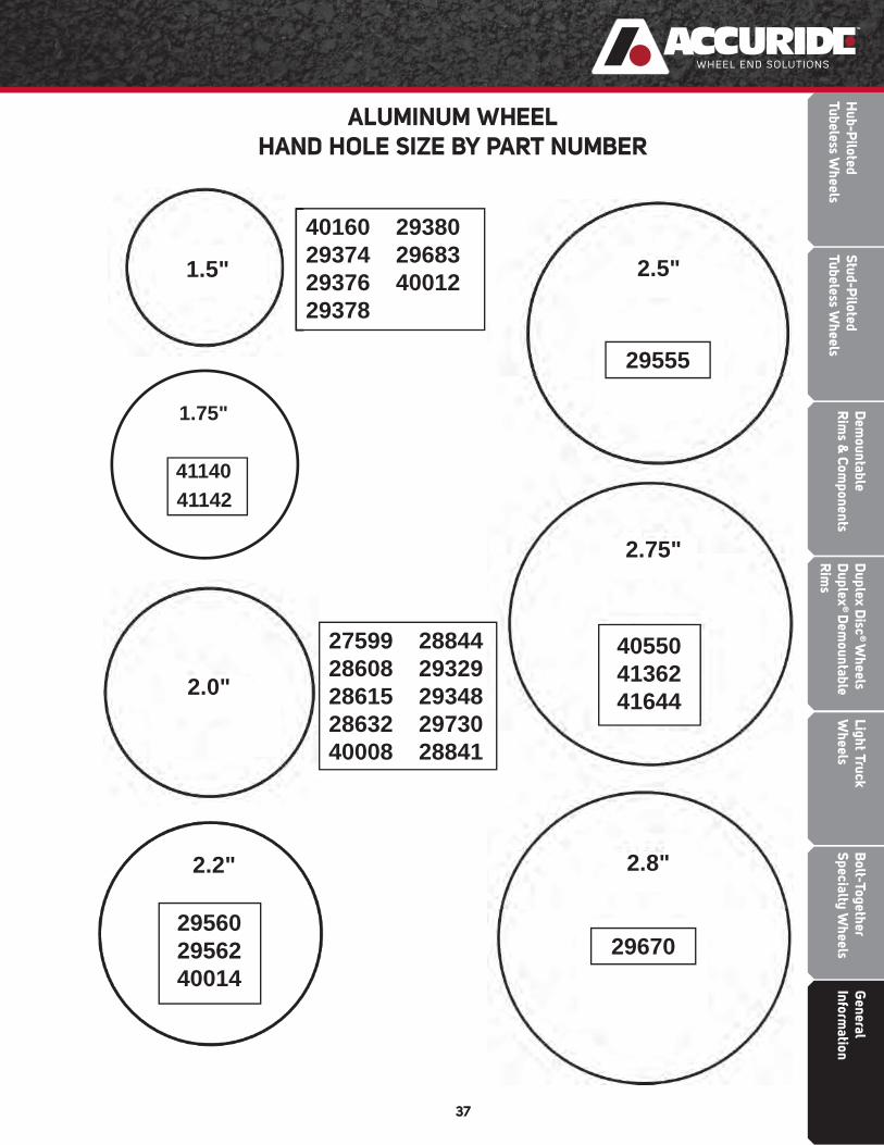
ALUMINUM WHEELHAND HOLE SIZE BY PART NUMBER
40160 2938029374 2968329376 4001229378
27599 2884428608 2932928615 2934828632 2973040008 28841
1.75"
4114041142
29670295602956240014
405504136241644
1.5" 2.5"
2.75"
2.0"
2.2" 2.8"
29555

Gen
eral
In
form
atio
nB
olt-
Toge
ther
Sp
ecia
lty
Whe
els
Ligh
t Tru
ck
Whe
els
Dup
lex
Dis
c® W
heel
s D
uple
x® D
emou
ntab
le
Rim
s
Dem
ount
able
Rim
s &
Com
pone
nts
Stud
-Pilo
ted
Tube
less
Whe
els
Hub
-Pilo
ted
Tube
less
Whe
els
38
TYPES OF ACCURIDE RIMS, RINGS,AND TYPICAL DISC-TO-RIM ATTACHMENT LOCATIONS
5° RADIAL COMMANDER®
3-PIECE TUBE-TYPE RIMS
15° TUBELESSALUMINUM WHEELS
15° TUBELESS STEEL WHEELS(Welded on Ledge)
FL 2-PIECE CONVERTIBLETUBE-TYPE RIMS
15° TUBELESS STEEL WHEELS(Welded on Well)
5° DROP CENTERDUAL STEEL WHEEL
5° DROP CENTERSINGLE STEEL WHEEL
Rim size Type
20 x 7.5 5°
20 x 8.0 5°
22 x 8.0 5°
24 x 8.0 5°
24 x 8.5 5°
Rim size Type
20 x 7.5 FL
Wheel size
19.5 x 7.50RW
19.5 x 6.00
19.5 x 6.75RW
19.5 x 8.25RW
22.5 x 7.50
22.5 x 8.25
22.5 x 9.00
24.5 x 8.25
Wheel size
19.5 x 6.00
19.5 x 6.00RW
19.5 x 6.75RW
Wheel size
17.5 x 6.75HC 22.5 x 7.50
17.5 x 8.25HC 22.5 x 8.25
19.5 x 7.50RW 22.5 x 9.00
19.5 x 8.25RW 24.5 x 8.25
22.5 x 6.75
Wheel size
16 x 6K
16 x 6.5J
16 x 7K
17 x 6K
17 x 7.5J
18 x 8J
Wheel size
16 x 6K
16 x 7K

Dem
ountableR
ims &
Components
Bolt-Together
Specialty Wheels
Light Truck W
heelsD
uplex Disc
® W
heels D
uplex®
Dem
ountable R
ims
Stud-Piloted
Tubeless Wheels
Hub-P
ilotedTubeless W
heels
General
Information
39
ACCURIDE TYPICAL PRODUCT STAMPING

Gen
eral
In
form
atio
nB
olt-
Toge
ther
Sp
ecia
lty
Whe
els
Ligh
t Tru
ck
Whe
els
Dup
lex
Dis
c® W
heel
s D
uple
x® D
emou
ntab
le
Rim
s
Dem
ount
able
Rim
s &
Com
pone
nts
Stud
-Pilo
ted
Tube
less
Whe
els
Hub
-Pilo
ted
Tube
less
Whe
els
40
HOW TO IDENTIFY DAMAGED RIMS/WHEELSRim/wheel components can become damaged. Check all metal surfaces for rust or corrosion buildup, cracks in metal, bent fl anges and side rings, deep rim tool marks on rings or in gutter areas. Watch for the problems illustrated in the following two pages and take the corrective actions to prevent further problems. Remember, it is dangerous to assemble cracked, bent, severely corroded, or sprung rim/wheel components. Such items should be destroyed and discarded.
RIM BASE CRACKS

Dem
ountableR
ims &
Components
Bolt-Together
Specialty Wheels
Light Truck W
heelsD
uplex Disc
® W
heels D
uplex®
Dem
ountable R
ims
Stud-Piloted
Tubeless Wheels
Hub-P
ilotedTubeless W
heels
General
Information
41
HOW TO IDENTIFY DAMAGED RIMS/WHEELS
DISC WHEEL CRACKS/BOLT HOLE DISTORTION
TUBELESS RIM LEAKS
Gen
eral
In
form
atio
nB
olt-
Toge
ther
Sp
ecia
lty
Whe
els
Ligh
t Tru
ck
Whe
els
Dup
lex
Dis
c® W
heel
s D
uple
x® D
emou
ntab
le
Rim
s
Dem
ount
able
Rim
s &
Com
pone
nts
Stud
-Pilo
ted
Tube
less
Whe
els
Hub
-Pilo
ted
Tube
less
Whe
els
42
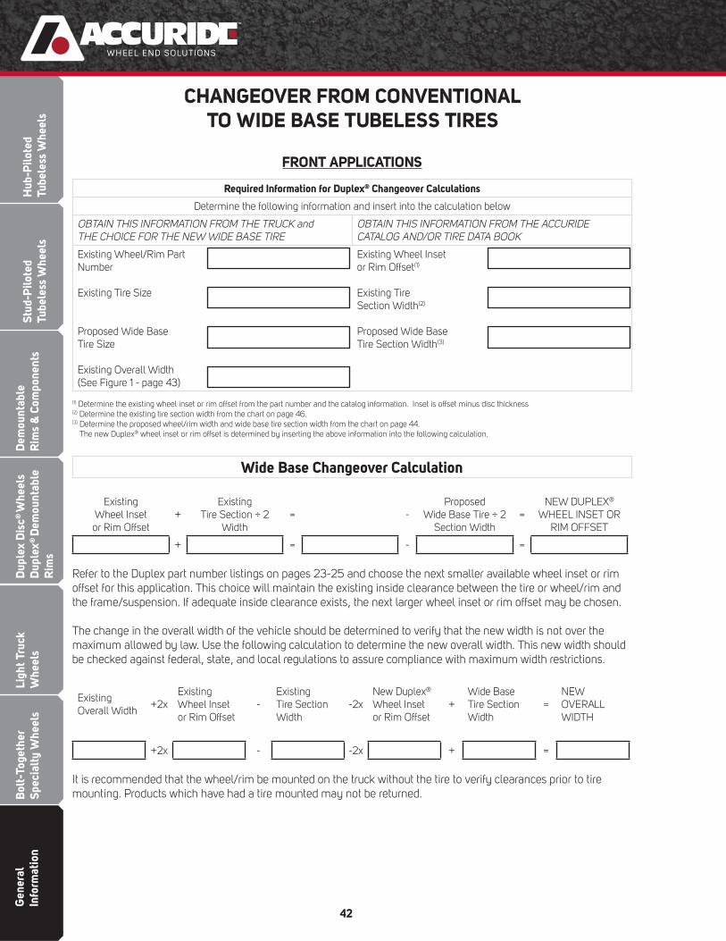
CHANGEOVER FROM CONVENTIONALTO WIDE BASE TUBELESS TIRES
FRONT APPLICATIONS
Required Information for Duplex® Changeover Calculations
Determine the following information and insert into the calculation below
OBTAIN THIS INFORMATION FROM THE TRUCK and THE CHOICE FOR THE NEW WIDE BASE TIRE
OBTAIN THIS INFORMATION FROM THE ACCURIDE CATALOG AND/OR TIRE DATA BOOK
Existing Wheel/Rim PartNumber
Existing Tire Size
Proposed Wide BaseTire Size
Existing Overall Width(See Figure 1 - page 43)
Existing Wheel Insetor Rim Offset(1)
Existing TireSection Width(2)
Proposed Wide BaseTire Section Width(3)
(1) Determine the existing wheel inset or rim offset from the part number and the catalog information. Inset is offset minus disc thickness(2) Determine the existing tire section width from the chart on page 46.(3) Determine the proposed wheel/rim width and wide base tire section width from the chart on page 44.
The new Duplex® wheel inset or rim offset is determined by inserting the above information into the following calculation.
Wide Base Changeover Calculation
ExistingWheel Inset
or Rim Offset+
Existing Tire Section ÷ 2
Width= -
Proposed Wide Base Tire ÷ 2
Section Width=
NEW DUPLEX®
WHEEL INSET ORRIM OFFSET
+ = - =
Refer to the Duplex part number listings on pages 23-25 and choose the next smaller available wheel inset or rim offset for this application. This choice will maintain the existing inside clearance between the tire or wheel/rim and the frame/suspension. If adequate inside clearance exists, the next larger wheel inset or rim offset may be chosen.
The change in the overall width of the vehicle should be determined to verify that the new width is not over the maximum allowed by law. Use the following calculation to determine the new overall width. This new width should be checked against federal, state, and local regulations to assure compliance with maximum width restrictions.
Existing Overall Width
+2xExisting Wheel Inset or Rim Offset
-Existing Tire Section Width
-2xNew Duplex® Wheel Inset or Rim Offset
+Wide Base Tire Section Width
=NEWOVERALLWIDTH
+2x - -2x + =
It is recommended that the wheel/rim be mounted on the truck without the tire to verify clearances prior to tire mounting. Products which have had a tire mounted may not be returned.

Dem
ountableR
ims &
Components
Bolt-Together
Specialty Wheels
Light Truck W
heelsD
uplex Disc
® W
heels D
uplex®
Dem
ountable R
ims
Stud-Piloted
Tubeless Wheels
Hub-P
ilotedTubeless W
heels
General
Information
43
CHANGEOVER FROM CONVENTIONAL TO WIDE BASE TUBELESS TIRES
FRONT APPLICATIONS CONTINUED
Wide Base Tire Section Width and Dimension ChartInformation from The 2014 Tire & Rim Association Yearbook
Tire Size(2) Rim Width Tire Section Width
15 22.5 11.7512.25
15.30 15.50(1)
445/50 22.5 14.00 17.52
385/65 22.5 11.7512.25
15.31 15.51(1)
16.5 22.5 13.0012.25
16.75 16.45(1)
425/65 22.5 12.2513.00
16.61 16.91(1)
445/65 22.5 12.2513.0014.00
17.18(1)
17.48 17.88(1)
18 22.5 13.0014.00
17.60(1)
18.00
(1) This value was calculated by the following formula: Tire section width will change 0.1" each 1/4" change in rim width from the design rim width.
(2) A denotes both radial and bias tires. Figure 1

Gen
eral
In
form
atio
nB
olt-
Toge
ther
Sp
ecia
lty
Whe
els
Ligh
t Tru
ck
Whe
els
Dup
lex
Dis
c® W
heel
s D
uple
x® D
emou
ntab
le
Rim
s
Dem
ount
able
Rim
s &
Com
pone
nts
Stud
-Pilo
ted
Tube
less
Whe
els
Hub
-Pilo
ted
Tube
less
Whe
els
44
SELECTED DUPLEX® CHANGEOVER APPLICATIONS 385/65R22.5 TIRE SIZE
SELECTED DUPLEX® CHANGEOVER APPLICATIONS 425/65R22.5 TIRE SIZE
Factors which may effect fi tment:• Drum clearance on older applications
• Inside clearance
• Maximum outside track (overall width) (max is usually 102")
Use the following recommendations:• Inside clearance will be preserved and the outside track will
increase by 9"
• For Hub-Piloted steel wheel applications:• 12.25 width - 29806
Alternative Recommendation• The new overall width will be increased 7½" and the inside
clearance will be reduced by ¾"
• For Hub-Piloted steel wheel applications: • 12.25 width - 29807
• For Stud-Piloted steel wheel applications:• 12.25 width - 29816
Factors which may effect fi tment:• Drum clearance on older applications
• Inside clearance
• Maximum outside track (overall width) (max is usually 102")
Use the following recommendations:• Note that the inside clearance will be reduced by ¾" and the
outside track will increase by 10"
• For Hub-Piloted steel wheel applications:• 12.25 width - 29806
Alternative Recommendation• The new overall width will be increased 8½" and the inside
clearance will now be reduced by 1½".
• For Hub-Piloted steel wheel applications: • 12.25 width - 29807
• For Stud-Piloted steel wheel applications:• 12.25 width - 29816
Note 1: Changeover also applies to 275/80 and 295/75 low profi le tires.

Dem
ountableR
ims &
Components
Bolt-Together
Specialty Wheels
Light Truck W
heelsD
uplex Disc
® W
heels D
uplex®
Dem
ountable R
ims
Stud-Piloted
Tubeless Wheels
Hub-P
ilotedTubeless W
heels
General
Information
45
SELECTED DUPLEX® CHANGEOVER APPLICATIONS TO ALUMINUM
SELECTED DUPLEX® CHANGEOVER APPLICATIONS – DRIVE/TRAILER
Factors which may effect fi tment:• Drum clearance
• Inside clearance
• Maximum outside track (width) (max is usually 102")
Use the following recommendations:• Hub-Piloted applications only
• 29374AOP
• New overall width is increased as follows:
• 385/65R22.5 tire - 3¾" each side of the vehicle
• 425/65R22.5 tire - 4¼" each side of the vehicle
• Reduces the inside clearance as follows:
• 385/65R22.5 tire - approx 1"
• 425/65R22.5 tire - approx 1½"
Alternative recommendation:• Hub-Piloted applications only
• 29683AOP
• Overall width increases an additional 2" each side from the dimensions shown above and in the sketch.
• Inside clearance is not changed from original.
Factors which may effect fi tment:• Drum clearance on older applications
• Centerline alignment is recommended for best distribution of bearing loads. If outside alignment changeovers are preferred, bearing loading should be verifi ed with axle manufacturer.
385/65R22.5 & 425/65R22.5 Recommendations:• Hub-Piloted applications:
• 12.25 width - Steel 29805; Aluminum 29378AOP (385 & 425 Tires)
• 13.00 width - Steel 29146; Aluminum 29380AOP (425 Tire Only)
• For Stud-Piloted applications:• 13.00 width - Steel 29818 (425 Tire Only)
445/50R22.5• Tractor Applications
• Hub-Piloted applications:• 14.00 width - Steel 29627; Aluminum 41142
• Trailer Applications• Hub-Piloted applications:
• 14.00 width - Steel 50172; Aluminum 41140
Note 1: Changeover also applies to 275/80 and 295/75 low profi le tires.
4164441362

Gen
eral
In
form
atio
nB
olt-
Toge
ther
Sp
ecia
lty
Whe
els
Ligh
t Tru
ck
Whe
els
Dup
lex
Dis
c® W
heel
s D
uple
x® D
emou
ntab
le
Rim
s
Dem
ount
able
Rim
s &
Com
pone
nts
Stud
-Pilo
ted
Tube
less
Whe
els
Hub
-Pilo
ted
Tube
less
Whe
els
46
DUAL SPACING OF WHEELS
As shown in the diagram below, the sum of the wheel offsets of the two wheels used equals the dual spacing. The recommended minimum dual spacing for tire clearance is shown in the chart to the right.
Tire clearance can be calculated by subtracting one tire section width from the sum of the two wheel offsets. This information is found in tire data books (also see chart). For more accuracy, the grown tire width at the rated load can be used instead of the new tire section width. This dimension can be obtained either by actual measurement of the tire width (including protective side ribs) or by referring to the tire manufacturer’s data book.
In addition to determining tire clearance, the wheeloffset directly affects two other important dimensions: (1) the vehicle clearance and (2) the overall vehicle width of tires (see diagram below).
Vehicle body clearance, which is the distance from the inside tire to the spring or other body structures, will change proportionally to any change in offset of the inside wheel.
The overall vehicle width of tires is the distance from the outside tire wall of one tire to the outside tire wall of the tire on the opposite end of the axle. This dimension will be altered correspondingly by an increase or decrease in wheel offset. Overall vehicle width will change proportionally to any offset changes of the wheel, if the tire projects beyond the body structure. The maximum vehicle width is regulated by law.
2014 Wheel Selection And Tire SpacingInformation from The Tire & Rim Association Yearbook
Tire Sizes(1)
Design
Rim
Width(2)
Tire
Section
Width(3)
Minimum
Dual
Spacing(3)
Light Truck
7.50 16LT 6.00 8.65 10.00LT265/70 17 8.00 10.71 12.44LT225/75 16 6.00 8.78 10.20LT245/75 16 7.00 9.76 11.34LT265/75 16 7.50 10.51 12.20LT285/75 16 8.00 11.26 13.07LT235/80 17 6.50 9.25 10.75LT215/85 16 6.00 8.50 9.88LT235/85 16 6.50 9.25 10.75LT255/85 16 7.00 10.04 11.658.00 16.5 6.00 8.00 9.008.75 16.5 6.75 8.75 9.909.50 16.5 6.75 9.50 10.70
Medium And Heavy Truck
11.00 24 8.00 11.55 13.2012.00 24 8.50 12.40 14.108 19.5 6.00 8.00 9.10225/70 19.5 6.75 8.90 10.009 17.5HC, 22.5 6.75 9.00 10.30235/80 22.5 6.75 9.17 10.31245/70 19.5 7.50 9.76 10.98245/75 22.5 7.50 9.76 10.98255/70 22.5 7.50 10.04 11.3010 17.5HC, 22.5 7.50 10.00 11.40265/70 19.5 7.50 10.31 11.61265/75 22.5 7.50 10.31 11.61275/80 22.5, 24.5 8.25 10.87 12.2411 17.5HC, 22.5, 24.5 8.25 11.00 12.50285/75 24.5 8.25 11.14 12.52295/75 22.5 9.00 11.73 13.19305/70 19.5 9.00 12.01 13.50305/75 22.5 9.00 12.01 13.5012 22.5, 24.5 9.00 11.80 13.5012.5 22.5 9.00 11.90 13.6012.75 22.5 9.00 12.27 ---315/80R22.5 9.00 12.28 13.82
(1) A denotes both radial and bias tires.(2) For additional approved rim contours and widths see page 49.(3) Tire section width and minimum dual spacings will change 0.1" for each 1/4"
change in rim width from the design rim width.

Dem
ountableR
ims &
Components
Bolt-Together
Specialty Wheels
Light Truck W
heelsD
uplex Disc
® W
heels D
uplex®
Dem
ountable R
ims
Stud-Piloted
Tubeless Wheels
Hub-P
ilotedTubeless W
heels
General
Information
47
DUAL SPACING OF DEMOUNTABLE RIMS
As shown in the diagram, the sum of the offsets of the two rims used, plus the width of the spacer band, equals the dual spacing of the demountable rim assembly. The recommended minimum dual spacing for each tire and rim combination is shown in the chart to the right. More spacing is required when tire chains are to be used.
The tire clearance can be calculated by subtracting one tire section width from the dual spacing (this information is found in Tire Data Books and the chart on this page). For more accuracy, the grown tire width at the rated load can be used instead of the new tire section width. This dimension can be obtained either by actual measurement of the tire width (including protective side ribs) or by referring to the tire manufacturer’s data book.
If there is suffi cient spoke length on the rear spoke wheel, spacing and tire clearance can be increased (by changing the spacer band width) (see pages 19 and 45). The clamp length must also be changed.
In addition to determining tire clearance, rim offset directly affects two other important dimensions: (1) vehicle clearance and (2) the overall vehicle width of the tires.
Vehicle body clearance, which is the distance from the inside tire to the spring or other body structures, will change proportionally to any change in offset of the inside rim.
The overall vehicle width of tires is the distance from the outside tire wall of one tire to the outside tire wall of the tire on the opposite end of the axle. This dimension will be altered correspondingly by an increase or decrease in rim offset. Overall vehicle width will change proportionally to any offset changes of the rim, if the tire projects beyond the body structure. The maximum vehicle width is restricted by law.
2014 Wheel Selection And Tire SpacingInformation from The Tire & Rim Association Yearbook
Tire Sizes(1)
Design
Rim
Width(2)
Tire
Section
Width
Minimum
Dual
Spacing(3)
Medium And Heavy Truck
11.00 24 8.00 11.55 13.2012.00 24 8.50 12.40 14.109 17.5HC, 22.5 6.75 9.00 10.30235/80 22.5 6.75 9.17 10.31245/75 22.5 7.50 9.76 10.98255/70 22.5 7.50 10.04 11.3010 17.5HC, 22.5 7.50 10.00 11.40265/75 22.5 7.50 10.31 11.61275/80 22.5, 24.5 8.25 10.87 12.2411 17.5HC, 22.5, 24.5 8.25 11.00 12.50285/75 24.5 8.25 11.14 12.52295/75 22.5 9.00 11.73 13.19305/75 22.5 9.00 12.01 13.5012 22.5, 24.5 9.00 11.80 13.5012.5 22.5 9.00 11.90 13.6012.75 22.5 9.00 12.27 ---315/80R22.5 9.00 12.28 13.82
(1) A denotes both radial and bias tires.(2) For additional approved rim contours and widths see page 49.(3) Tire section width and minimum dual spacings will change 0.1" for each 1/4"
change in rim width from the design rim width.
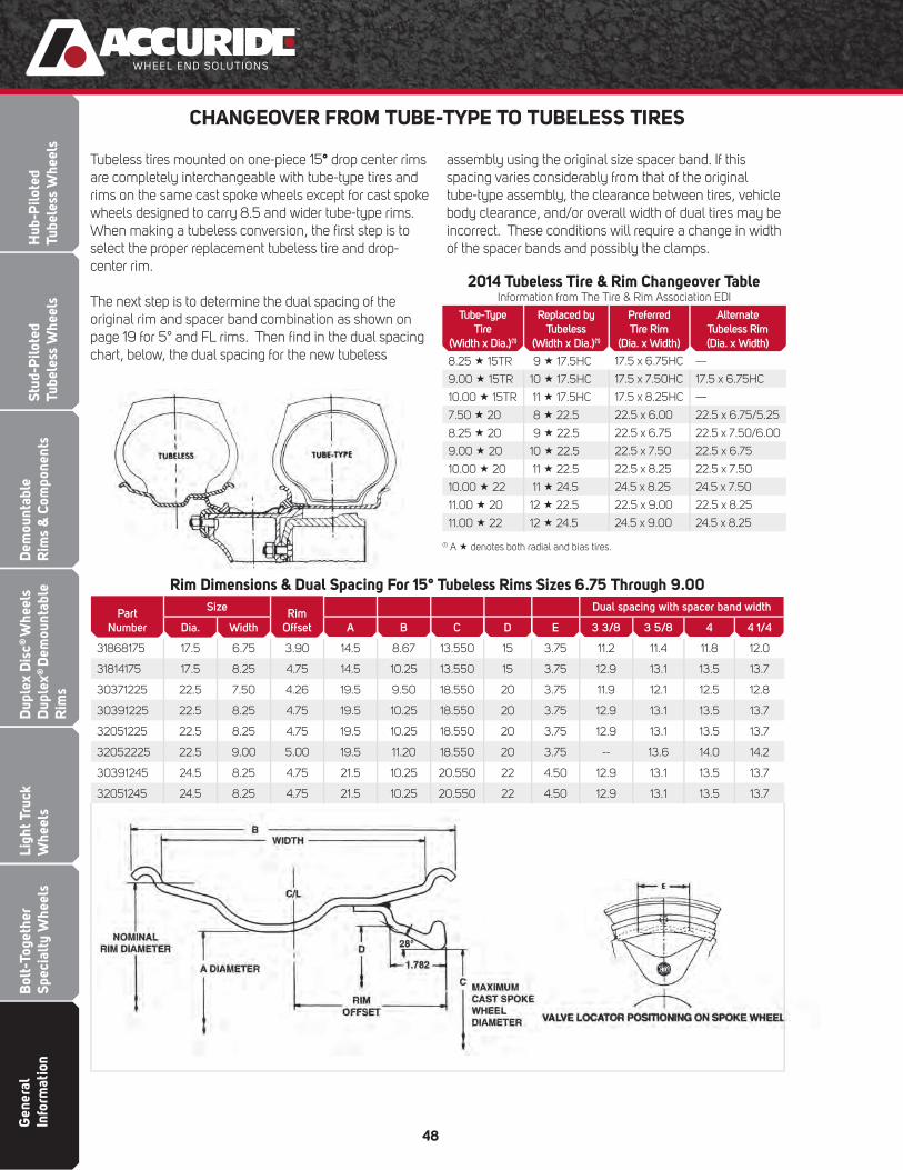
Gen
eral
In
form
atio
nB
olt-
Toge
ther
Sp
ecia
lty
Whe
els
Ligh
t Tru
ck
Whe
els
Dup
lex
Dis
c® W
heel
s D
uple
x® D
emou
ntab
le
Rim
s
Dem
ount
able
Rim
s &
Com
pone
nts
Stud
-Pilo
ted
Tube
less
Whe
els
Hub
-Pilo
ted
Tube
less
Whe
els
48
CHANGEOVER FROM TUBE-TYPE TO TUBELESS TIRES
Tubeless tires mounted on one-piece 15° drop center rims are completely interchangeable with tube-type tires and rims on the same cast spoke wheels except for cast spoke wheels designed to carry 8.5 and wider tube-type rims. When making a tubeless conversion, the fi rst step is to select the proper replacement tubeless tire and drop-center rim.
The next step is to determine the dual spacing of the original rim and spacer band combination as shown on page 19 for 5° and FL rims. Then fi nd in the dual spacing chart, below, the dual spacing for the new tubeless
assembly using the original size spacer band. If this spacing varies considerably from that of the original tube-type assembly, the clearance between tires, vehicle body clearance, and/or overall width of dual tires may be incorrect. These conditions will require a change in width of the spacer bands and possibly the clamps.
2014 Tubeless Tire & Rim Changeover TableInformation from The Tire & Rim Association EDI
Tube-Type
Tire
(Width x Dia.)(1)
Replaced by
Tubeless
(Width x Dia.)(1)
Preferred
Tire Rim
(Dia. x Width)
Alternate
Tubeless Rim
(Dia. x Width)
8.25 15TR 9 17.5HC 17.5 x 6.75HC —
9.00 15TR 10 17.5HC 17.5 x 7.50HC 17.5 x 6.75HC
10.00 15TR 11 17.5HC 17.5 x 8.25HC —
7.50 20 8 22.5 22.5 x 6.00 22.5 x 6.75/5.25
8.25 20 9 22.5 22.5 x 6.75 22.5 x 7.50/6.00
9.00 20 10 22.5 22.5 x 7.50 22.5 x 6.75
10.00 20 11 22.5 22.5 x 8.25 22.5 x 7.50
10.00 22 11 24.5 24.5 x 8.25 24.5 x 7.50
11.00 20 12 22.5 22.5 x 9.00 22.5 x 8.25
11.00 22 12 24.5 24.5 x 9.00 24.5 x 8.25
(1) A denotes both radial and bias tires.
Rim Dimensions & Dual Spacing For 15° Tubeless Rims Sizes 6.75 Through 9.00
Part
Number
SizeRim
Offset
Dual spacing with spacer band width
Dia. Width A B C D E 3 3/8 3 5/8 4 4 1/4
31868175 17.5 6.75 3.90 14.5 8.67 13.550 15 3.75 11.2 11.4 11.8 12.0
31814175 17.5 8.25 4.75 14.5 10.25 13.550 15 3.75 12.9 13.1 13.5 13.7
30371225 22.5 7.50 4.26 19.5 9.50 18.550 20 3.75 11.9 12.1 12.5 12.8
30391225 22.5 8.25 4.75 19.5 10.25 18.550 20 3.75 12.9 13.1 13.5 13.7
32051225 22.5 8.25 4.75 19.5 10.25 18.550 20 3.75 12.9 13.1 13.5 13.7
32052225 22.5 9.00 5.00 19.5 11.20 18.550 20 3.75 -- 13.6 14.0 14.2
30391245 24.5 8.25 4.75 21.5 10.25 20.550 22 4.50 12.9 13.1 13.5 13.7
32051245 24.5 8.25 4.75 21.5 10.25 20.550 22 4.50 12.9 13.1 13.5 13.7

Dem
ountableR
ims &
Components
Bolt-Together
Specialty Wheels
Light Truck W
heelsD
uplex Disc
® W
heels D
uplex®
Dem
ountable R
ims
Stud-Piloted
Tubeless Wheels
Hub-P
ilotedTubeless W
heels
General
Information
49
CHART FOR PROPERLY MATCHINGTRUCK TIRES TO RIMS/WHEELS
Information obtained from the 2014 Tire & Rim Association Yearbook
Tire Size(1) Approved Rim Contours(2)
LIGHT TRUCKS
6.50 16LT 4½K, 4.50E, 5K, 6K, 6L
7.50 16LT 5.50F (SDC), 6K, 6L, 6½L, 7L
LT225/75 16 6J, 6½ J, 6K, 6½K, 6½L, 7J, 7K, 7L
LT245/75 16 6½J, 6½K, 6½L, 7J, 7K, 7L, 7½J, 8J
LT265/75 16 7J, 7K, 7L, 7½J, 8J, 8L
LT285/75 16 7½J, 8J, 8½J, 8L, 8LB, 8KB, 9J
LT215/85 16 5½J, 5½K, 5.50F (SDC), 6J, 6K,6½J, 6½L, 7J, 7K, 7L
LT235/80 17 6J, 6½J, 7J, 7½J
LT235/85 16 6J, 6K, 6L, 6½J, 6½L, 7J, 7K, 7L, 7½J
LT255/85 16 6½J, 6½L, 7KB, 7J, 7K, 7L, 8J,8KB, 8L, 8LB
LT235/70 16 6J, 6K, 6L, 6½J, 6½K, 6½L, 7J, 7K,7KB, 7L, 7½J
LT255/70 16 6½J, 6½K, 6½L, 7J, 7K, 7KB, 7L,7½J, 8J, 8KB, 8L, 8LB, 8½J
LT265/70 17 7J, 7K, 7KB, 7L, 7½J, 8J, 8KB, 8L,8LB, 8½J, 9J
LT275/70 16 7J, 7½J, 8J, 8½J
8.75 16.5 6.00, 6.75
9.50 16.5 6.75, 8.25
LOW PLATFORM TRAILERS
9R17.5HC 6.75HC
215/75R 17.5HC 6.00HC, 6.75HC
10R17.5HC 6.75HC, 7.50HC
11R17.5HC 8.25HC
(1) A denotes both radial and bias tires. An R indicates radial tires only.(2) SDC denotes semi-drop center rims.Note: For tire sizes not shown, consult the Tire Manufacturer for approved rim contours.
Tire Size(1) Approved Rim Contours(2)
MEDIUM AND HEAVY DUTY TRUCKS
11.00 24 7.5, 8.0, 8.5, 8.50VM
12.00 24 8.0, 8.5, 8.50VM, 9.0
8 19.5 5.25, 6.00, 6.00RW, 6.75, 6.75RW
225/70R 19.5 6.00, 6.00RW, 6.75, 6.75RW
245/70R 19.5 6.75, 6.75RW, 7.50, 7.50RW
265/70R 19.5 7.50, 7.50RW, 8.25, 8.25RW
305/70R 19.5 8.25, 8.25RW, 9.00
8 22.5 5.25, 6.00, 6.75
9 22.5 6.00, 6.75, 7.50
10 22.5 6.75, 7.50, 8.25
235/80R 22.5 6.75, 7.50
245/75R 22.5 6.75, 7.50
255/70R 22.5 7.50, 8.25
265/75R 22.5 7.50, 8.25
11 22.5 7.50, 8.25
275/80R 22.5 7.50, 8.25
295/75R 22.5 8.25, 9.00
305/70R 22.5 8.25, 9.00
12 22.5 8.25, 9.00
12.5 22.5 8.25, 9.00
12.75 22.5 8.25, 9.00
315/80R22.5 9.00, 9.75
11 24.5 7.50, 8.25
275/80R 24.5 7.50, 8.25
12 24.5 8.25, 9.00
285/75R 24.5 8.25
WIDE BASE (DUPLEX®)
15 19.5 11.75, 12.25
16.5 19.5 12.25, 13.00
18 19.5 13.00, 14.00
15 22.5 11.75, 12.25
385/65R 22.5 11.75, 12.25
16.5 22.5 12.25, 13.00
425/65R 22.5 11.75, 12.25, 13.00
445/50R 22.5 14.00
445/65R 22.5 12.25, 13.00, 14.00
455/55R 22.5 14.00
18 22.5 13.00, 14.00
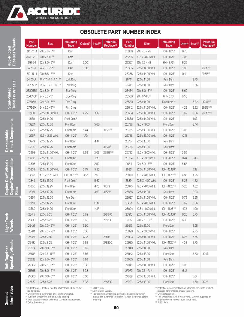
Gen
eral
In
form
atio
nB
olt-
Toge
ther
Sp
ecia
lty
Whe
els
Ligh
t Tru
ck
Whe
els
Dup
lex
Dis
c® W
heel
s D
uple
x® D
emou
ntab
le
Rim
s
Dem
ount
able
Rim
s &
Com
pone
nts
Stud
-Pilo
ted
Tube
less
Whe
els
Hub
-Pilo
ted
Tube
less
Whe
els
50
OBSOLETE PART NUMBER INDEX
(1) Outset/lnset—(Inches) See Pg. 25 footnote (3) or Pg. 56 for defi nition.
(2) Check vehicle clearances prior to mounting tire. (3) Tubeless wheel/rim available. See catalog.(4) Well Welded—check clearance I.D. upon replacement. (5) Offset Difference.
(6) 13.00" Rim.(7) Reinforced Flanges.(8) Replacement wheel has a different disc contour which
allows less clearance for brakes. Check clearance before ordering.
(9) Potential replacement has an alternate rim contour which requires different side and/or lock ring.
(10) Check clearance.(11) This wheel has a .453" valve hole. Wheels supplied on original vehicle have a .625" valve hole.(12) 7.50" Rim.
Part Number
SizeMounting
TypeOutset(1) Inset(1)
Potential Replace(2)
26039 20 x 7.5 - MS 10H - 11.25" 6.75
26205 19.5 x 14.00 WHL 10H - 11.25" 3.06
26357 20 x 7.5 - MS 6H - 8.75" 6.25
26385 22.5 x 14.00 WHL 10H - 11.25" 3.06 29818(5)
26386 22.5 x 14.00 WHL 10H - 11.25" 0.44 29818(5)
26414 22.5 x 14.00 Rear Dem 2.75
26415 22.5 x 14.00 Rear Dem 0.56
26464 20 x 8.0 - 5° (3) 10H - 11.25" 6.62
26538 20 x 6.5 FL (3) 6H - 8.75" 6.50
26580 22.5 x 14.00 Front Dem (4) 5.82 13244(6)(5)
26642 22.5 x 14.00 WHL 10H - 11.25" 4.25 3.62 29818(6)(5)
26654 22.5 x 14.00 WHL 10H - 11.25" 3.69 3.06 29818(6)(5)
26660 22.5 x 14.00 WHL 10H - 11.25" 1.63
26738 19.5 x 13.00 Front Dem 2.44
26785 22.5 x 13.00 WHL 10H - 11.25" 3.06
26786 22.5 x 13.00 WHL 10H - 11.25" 0.41
26787 22.5 x 13.00 Rear Dem
26788 22.5 x 13.00 Rear Dem
26793 19.5 x 13.00 WHL 10H - 11.25" 3.06
26794 19.5 x 13.00 WHL 10H - 11.25" 0.44 0.19
26811 22 x 8.0 - 5° (3) 10H - 11.25" 6.65
26831 22.5 x 14.00 WHL 10H - 13.188" 7.12
26870 19.5 x 14.00 WHL 10H - 11.25"(4) 4.88 4.25
26874 22.5 X 14.00 WHL 10H - 11.25" 5.25 4.62
26875 19.5 x 14.00 WHL 10H - 11.25"(4) 5.25 4.62
26886 22.5 x 14.00 Rear Dem 2.93
26887 22.5 x 14.00 WHL 10H - 11.25" 5.75 5.25
26891 19.5 x 14.00 WHL 10H - 11.25" 3.69 3.06
26894 19.5 x 14.00 WHL 10H - 11.25"(4) 4.72 4.09
26915 22.5 x 14.00 WHL 10H - 13.188" 6.25 5.75
26917 20 x 7.5 - FL (3) 10H - 11.25" 6.38
26919 22.5 x 13.00 Front Dem 3.25
26920 19.5 x 13.00 WHL 10H - 11.25" 2.75
26934 22.5 x 14.00 WHL 10H - 11.25" 6.25 5.75
26935 22.5 x 14.00 WHL 10H - 11.25"(4) 4.38 3.75
26940 22.5 x 14.00 Rear Dem
26942 22.5 x 13.00 Front Dem 5.83 13244
26965 22.5 x 14.00 Rear Dem
27048 22.5 x 14.00 WHL 10H - 11.25" 3.06
27079 20 x 7.5 - FL (3) 10H - 11.25" 6.12
27089 22.5 x 13.00 WHL 10H - 11.25" 5.81
27093 22.5 x 13.00 Front Dem 4.50 13228
Part Number
SizeMounting
TypeOutset(1) Inset(1)
Potential Replace(2)
240 - 5° - 1 20 x 7.0 - 5° (3) Dem
262FL2 - 1 20 x 7.5 FL (3) Dem
276-5-1 22 x 8.0 - 5° (3) Dem 5.00
277-5-1 24 x 8.0 - 5° (3) Dem 5.00
312 - 5 - 1 20 x 8.5 - 5° (3) Dem
241D5LR 22 x 7.0 - 7.5 - 8.0 - 5° Lock Ring
242D5LR 24 x 7.0 - 7.5 - 8.0 - 5° Lock Ring
263D5SR 22 x 8.0 - 5° Side Ring
264D5SR 24 x 8.0 - 5° Side Ring
276D51X 22 x 8.0 - 5° (3) Rim Only
277D51X 24 x 8.0 - 5° (3) Rim Only
13180 22.5 x 14.00 WHL 10H - 11.25" 4.75 4.12
13189 22.5 x 14.00 Front Dem(4)
13224 22.5 x 13.00 Front Dem 5.00
13229 22.5 x 12.25 Front Dem 5.44 31679(5)
13257 19.5 x 12.25 WHL 10H - 11.25" 1.70
13279 22.5 x 12.25 Front Dem 4.44
13290 22.5 x 12.25 Front Dem 31674(5)
13293 22.5 x 14.00 WHL 10H - 11.25" 3.69 3.06 29818(6)(5)
13298 22.5 x 13.00 Front Dem 1.20
13308 22.5 x 13.00 Front Dem 2.50
13333 22.5 x 14.00 WHL 10H - 11.25" 5.75 5.25
13348 19.5 x 12.25 WHL 10H - 11.25"(7) 3.12 2.50
13349 22.5 x 13.00 Front Dem(7) 5.62
13350 22.5 x 12.25 Front Dem 4.75 31679
13351 22.5 x 12.25 Front Dem 3.63 31674(5)
13354 22.5 x 13.00 Rear Dem
13491 22.5 x 12.25 Front Dem 6.44
13580 22.5 x 14.00 Front Dem 4.17
25415 22.5 x 8.25 10H - 11.25" 6.62 27834C
25430 22.5 x 8.25 10H - 11.25" 6.62 27833C
25438 20 x 7.0 - 5° (3) 10H - 11.25" 6.50
25441 20 x 7.5 - FL (3) 10H - 11.25" 6.50
25451 22.5 x 7.50 10H - 11.25" 6.12 27403
25495 22.5 x 8.25 10H - 11.25" 6.62 27833C
25524 20 x 8.0 - 5° (3) 10H - 11.25" 6.62
25617 22 x 7.5 - 5° (3) 10H - 11.25" 6.56
25622 22 x 8.0 - 5° (3) 10H - 11.25" 6.88
25662 20 x 7.5 - 5° (3) 10H - 11.25" 6.38
25666 20 x 8.0 - 5° (3) 10H - 11.25" 6.38
25668 20 x 8.0 - 5° (3) 10H - 11.25" 6.88
25672 22.5 x 8.25 10H - 11.25" 6.38 27833C

Dem
ountableR
ims &
Components
Bolt-Together
Specialty Wheels
Light Truck W
heelsD
uplex Disc
® W
heels D
uplex®
Dem
ountable R
ims
Stud-Piloted
Tubeless Wheels
Hub-P
ilotedTubeless W
heels
General
Information
51
OBSOLETE PART NUMBER INDEX
Part Number
SizeMounting
TypeOutset(1) Inset(1)
Potential Replace(2)
27760 22.5 x 14.00 WHL 10H-13.188"HD(7) 7.12 28465(6)
27765 22.5 x 8.25 10H - 11.25"B 6.62 27834C(10)
27766 22.5 x 8.25 10H - 11.25"B 6.62 27834C(10)
27772 16 x 5.50-F 8H - 6.50" 5.00 29587
27773 22.5 x 12.25 WHL 10H - 13.188"HD 6.25 28465(6)
27774 19.5 x 6.00 8H - 6.50" 5.00 29015
27775 19.5 x 6.00 10-H - 7.25" 5.00"
27784 22.5 x 6.75 6H - 8.75" 5.93
27785 22.5 x 6.75 10H - 8.75" 6.00
27791 22.5 x 14.00 WHL 10H - 13.188"HD 7.12 28465(6)
27796 16 x 6K 8H - 6.50" I °C 5.00
27833 22.5 x 8.25 10H - 11.25" 6.62 27833C
27834 22.5 x 8.25 10H - 11.25"B 6.62 27834C
27836 22.5 x 8.25 10H - 11.25" 6.62 27404(10)
27910 17.5 x 6.75 6H - 8.75" 5.62 28145
27913 22.5 x 13.00 WHL 10H - 11.25" 0.44 29818(5)
27917 22.5 x 13.00 WHL 10H - 11.25" 3.06
27922 16 x 5.5-F 8H - 6.50" 5.00 29587
27924 22.5 x 12.25 WHL 10H - 11.25" 0.44 29818(5)(6)
27944 22.5 x 6.75 10H - 11.25" 5.91
27945 20 x 7.5 -5° (3) 10H - 11.25" 6.50
27952 22.5 x 12.25 WHL 10H - 11.25" 5.18 4.56 29816
27953 22.5 x 12.25 WHL 10H - 11.25" 2.25 1.62
27954 22.5 x 12.25 WHL 10H - 11.25" 3.12 2.50 29816(6)
27955 22.5 x 12.25 WHL 10H - 11.25" 4.25 3.62
27956 22.5 x 12.25 WHL 10H - 11.25" 4.75 4.12
27957 22.5 x 12.25 WHL 10H - 11.25" 5.75 5.12 29816
27958 22.5 x 13.00 WHL 10H - 11.25" 5.88 5.25
27959 22.5 x 13.00 WHL 10H - 11.25" 3.69 3.06 29818(5)
27960 22.5 x 13.00 WHL 10H - 11.25" 5.25 4.62
27964 22.5 x 13.00 WHL 10H - 11.25" 4.25 3.62
27967 19.5 x 12.25 WHL 10H - 8.75" 3.12 2.5
27968 19.5 x 12.25 WHL 10H - 8.75" 0.44
27969 19.5 x 12.25 WHL 10H - 11.25" 3.12 2.50
27970 19.5 x 12.25 WHL 10H - 11.25" 0.44
27980 19.5 x 13.00 WHL 10H - 11.25" 4.88 4.25
27981 19.5 x 13.00 WHL 10H - 11.25" 5.25 4.62
27982 19.5 x 13.00 WHL 10H - 11.25" 4.72 4.09
27983 19.5 x 13.00 WHL 10H - 11.25" 4.38 3.75
27984 19.5 x 13.00 WHL 10H - 11.25" 0.31
27985 19.5 x 13.00 WHL 10H - 11.25" 3.06 2.43
27994 16 x 6KS 8H - 6.50" 5.00 29587(11)
Part Number
SizeMounting
TypeOutset(1) Inset(1)
Potential Replace(2)
27121 20 x 6.5 - CR (3) 6H - 8.75" 5.62
27122 20 x 6.5 - CR (3) 6H - 8.75" 6.00
27123 20 x 6.5 - CR (3) 10H - 11.25" 6.00
27124 20 x 7.0 - CR (3) 6H - 8.75" 6.12
27126 20 x 7.0 - CR (3) 10H - 11.25" 6.44
27163 20 x 6.5 - CR (3) 10H - 8.75" 6.00
27166 22 x 7.5 - LB (3) 10H - 11.25" 6.50
27196 20 x 7.5 - LB (3) 10H - 11.25" 6.50
27211 19.5 x 12.25 WHL 10H - 8.75"(4) 3.12 2.50
27212 19.5 x 12.25 WHL 10H - 8.75" 0.44
27215 19.5 x 12.25 WHL 10H - 11.25"(4) 3.12 2.50
27216 19.5 x 12.25 WHL 10H - 11.25" 0.44
27221 22.5 x 12.25 WHL 10H - 11.25" 3.12 2.50 29816(6)
27222 22.5 x 12.25 WHL 10H - 11.25" 0.44
27225 22.5 x 12.25 Rear Dem 0.38 0.38
27226 22.5 x 12.25 Rear Dem 1.87 1.87
27233 22.5 x 12.25 WHL 10H - 11.25" 4.88
27234 22.5 x 12.25 WHL 10H - 11.25" 5.06 4.56 29816(5)
27235 22.5 x 12.25 WHL 10H - 11.25" 5.62 5.12 29816(5)
27236 22.5 x 12.25 WHL 10H - 11.25" 6.80 6.30 29816(5)
27238 19.5 x 12.25 Front Dem 2.44
27239 22.5 x 12.25 WHL 10H - 13.188" 5.87
27256 22.5 x 12.25 WHL 10H - 11.25" 6.25 5.75 29234
27257 22.5 x 12.25 WHL 10H - 11.25" 2.25 1.62
27258 22.5 x 12.25 WHL 10H - 11.25" 6.39 5.89 29816
27271 22.5 x 12.25 WHL 10H - 11.25" 4.62 4.12
27292 22.5 x 12.25 WHL 10H - 11.25" 7.06 6.56 29816(5)
27344 20 x 7.0 - LB (3) 10H - 11.25" 6.12
27355 22.5 x 14.00 WHL 10H - 13.188"HD 6.62 28465(6)
27461 22.5 x 8.25 10H - 11.25" 6.62 27833C(10)
27471 22.5 x 8.25 AL 10H - 11.25" 6.59 28615
27503 22.5 x 8.25 10H - 11.25" 6.62 27404(10
27611 22.5 x 8.25 10H - 11.25" 6.62 27834C (10)
27685 22.5 x 7.50 10H - 11.25" 6.44 27403
27686 22.5 x 8.25 10H - 11.25" 6.62 27833C(10)
27688 24.5 x 8.25 10H - 11.25" 6.62 27406
27709 22.5 x 8.25 10H - 11.25" 6.62 27834C(10)
27721 22.5 x 14.00 Front Dem 4.75 13228(6)
27727 20 x 6.5 - LB (3) 10H - 8.75" 5.84
27728 20 x 7.0 - LB (3) 10H - 8.75" 6.02
27742 22.5 x 12.25 WHL 10H - 13.188" 6.30
27756 16 x 6KS 8H - 6.50" 5.00 29587(11)
(1) Outset/lnset—(Inches) See Pg. 25 footnote (3) or Pg. 56 for defi nition.
(2) Check vehicle clearances prior to mounting tire. (3) Tubeless wheel/rim available. See catalog.(4) Well Welded—check clearance I.D. upon replacement. (5) Offset Difference.
(6) 13.00" Rim.(7) Reinforced Flanges.(8) Replacement wheel has a different disc contour which
allows less clearance for brakes. Check clearance before ordering.
(9) Potential replacement has an alternate rim contour which requires different side and/or lock ring.
(10) Check clearance.(11) This wheel has a .453" valve hole. Wheels supplied on original vehicle have a .625" valve hole.(12) 7.50" Rim.

Gen
eral
In
form
atio
nB
olt-
Toge
ther
Sp
ecia
lty
Whe
els
Ligh
t Tru
ck
Whe
els
Dup
lex
Dis
c® W
heel
s D
uple
x® D
emou
ntab
le
Rim
s
Dem
ount
able
Rim
s &
Com
pone
nts
Stud
-Pilo
ted
Tube
less
Whe
els
Hub
-Pilo
ted
Tube
less
Whe
els
52
Part Number
SizeMounting
TypeOutset(1) Inset(1)
Potential Replace(2)
27995 16.5 x 6.00 8H - 6.50" 5.00
27997 22.5 x 13.00 Rear Dem 2.75
27998 22.5 x 13.00 Rear Dem 2.00
27999 22.5 x 12.25 Rear Dem 1.88
28000 16.5 x 6.75 8H - 6.50 I°C 5.38
28001 22.5 x 12.25 Rear Dem 1.88
28004 19.5 x 6.00 10H - 8.75" 4.75
28118 22.5 x 12.25 WHL 10H - 11.25" 0.44
28119 22.5 x 12.25 WHL 10H - 11.25" 2.25 1.62
28120 22.5 x 12.25 WHL 10H - 11.25" 3.12 2.50 29816(5)
28122 22.5 x 14.00 WHL 10H - 11.25" 4.25 3.62
28124 22.5 x 12.25WHL 10H - 11.25" 4.90 4.28
28125 22.5 x 12.25WHL 10H - 11.25" 4.25 3.62
28126 22.5 x 12.25 WHL 10H - 11.25" 5.75 5.12 29816(5)
28127 22.5 x 13.00 WHL 10H - 11.25" 3.06
28128 22.5 x 13.00 WHL 10H - 11.25" 0.44 29818(5)
28132 22.5 x 12.25 WHL 10H - 11.25" 6.38 5.75 29816(6)
28157 22.5 x 6.75 6H - 8.75" 5.94
28158 22.5 x 6.75 10H - 11.25" 5.93
28160 22.5 x 6.75 10H - 8.75" 5.93
28165 22.5 x 12.25 WHL 10H - 11.25" 5.31 4.68 29816
28167 22.5 x 13.00 WHL 10H - 13.188"HD 7.12 28465
28169 22.5 x 13.00 WHL 10H - 11.25" 3.44 2.51 29816(5)
28174 22.5 x 13.00 WHL 10H - 13.188"HD 6.12
28175 22.5 x 12.25 WHL 10H - 13.188"HD 6.25
28177 16 x 6K 8H - 6.50" 5.00 29587(11)
28179 19.5 x 6.00RW 6H - 8.75" 4.75
28184 19.5 x 13.00 WHL 10H - 11.25" 4.72 4.09
28192 22.5 x 9.00 10H - 11.25" 3.12
28308 16 x 6K 8H - 6.50" 0.50
28322 16 x 6K 8H - 6.50" I °C 5.00
28324 17.5 x 8.25HC 10H - 8.75" 6.62 28112
28326 22.5 x 13.00 WHL 10H - 11.25" 5.38 4.75 28684(5)
28327 22.5 x 13.00 WHL 10H - 11.25" 4.24 3.62
28333 16 x 6K 8H - 6.50" 5.00 29579(11)
28338 22.5 x 13.00 WHL 10H - 13.188"HD 6.12 28465
28348 16.5 x 6.00 8H - 6.50" 5.00
28353 16 x 6K 8H - 6.50" I °C 5.00
28356 16.5 x 6.00 8H - 6.50" I °C 5.00
28368 22.5 x 7.50 10H - 335mm 6.50
28374 16 x 6K 8H - 6.50" 5.00 29587(11)
28375 16 x 6K 10H - 7.25 5.35
OBSOLETE PART NUMBER INDEX
Part Number
SizeMounting
TypeOutset(1) Inset(1)
Potential Replace(2)
28377 20 x 7.5 - FL (3) 10H - 11.25" 6.25
28378 16 x 6K 8H - 6.50" 0.50
28379 22.5 x 13.00 WHL 10H-13.188"HD(7) 7.12 28465(5)
28396 22.5 x 13.00 WHL 10H-13.188"HD(7) 6.81 28465(5)
28408 22.5 x 8.25 10H - 285.75mm 6.62 50408
28414 22.5 x 6.75 8H - 275mm 5.93
28415 22.5 x 7.50 8H - 275mm 6.44 29028
28433 19.5 x 14.00 WHL 10H - 11.25" 4.63 4.00 29307
28445 22.5 x 13.00 WHL 10H - 11.25" 5.88 5.25 28684
28450 22.5 x 8.25AL 10H - 285.75mm 6.59 41644
28452 24.5 x 8.25AL 10H - 285.75mm 6.59 41362
28460 20 x 6.5 - CR (3) 8H - 275mm 6.00
28466 19.5 x 6.75 8H - 275mm 5.50 50180
28473 24.5 x 8.25 10H - 11.25" 6.59 27599
28474 22.5 x 8.25 10H - 11.25" 6.59 28615
28476 22.5 x 8.25 10H - 11.25" 6.62 28476C
28484 22.5 x 8.50 8H - 275mm 6.62
28487 22.5 x 8.25 10H - 285.75mm 6.62 50487
28492 22.5 x 7.50 10H - 335mm 6.50
28511 16 x 6K 8H - 6.50" 5.00 29579
28512 16 x 6K 8H - 6.50" 5.35 29579
28513 16 x 6K 10H - 7.25 5.35
28520 19.5 x 6.00 6H - 8.75" 2.50
28532 19.5 x 6.75 8H - 275mm 5.66 50180
28537 20 x 7.5 LW (3) 10H - 11.25" 6.50
28538 20 x 8.0 LW (3) 10H - 11.25" 6.88
28542 22.5 x 9.00 10H - 285.75mm 7.00 29300
28546 16 x 7K 8H - 6.50" 0.25 29508
28547 24.5 x 8.25 10H - 285.75mm 6.59 29699
28548 22.5 x 8.25 10H - 285.75mm 6.59 29697
28550 22.5 x 12.25 Rear Dem 1.88
28551 22.5 x 13.00 Rear Dem 2.75
28560 22.5 x 8.25AL 10H - 11.25" 6.59 28632
28572 22.5 x 13.00 10H - 13 3/16" 6.12 28465
28603 16 x 6K 8H - 6.50" 5.00 29587
28609 22.5 x 6.75 6H - 8.75" 5.93
28612 19.5 x 6.75RW 8H - 275mm 5.60 50180
28613 22.5 x 8.25AL 10H - 285.75mm 6.59 40008
28618 16 x 6K 8H - 6.50" 5.15 29579
28623 16 x 6K 8H - 6.50" 5.00 29587
28624 22.5 x 7.50 10H - 285.75mm 2.62
28626 22.5 x 8.25-15° 10H - 11.25" 6.59 28584
(1) Outset/lnset—(Inches) See Pg. 25 footnote (3) or Pg. 56 for defi nition.
(2) Check vehicle clearances prior to mounting tire. (3) Tubeless wheel/rim available. See catalog.(4) Well Welded—check clearance I.D. upon replacement. (5) Offset Difference.
(6) 13.00" Rim.(7) Reinforced Flanges.(8) Replacement wheel has a different disc contour which
allows less clearance for brakes. Check clearance before ordering.
(9) Potential replacement has an alternate rim contour which requires different side and/or lock ring.
(10) Check clearance.(11) This wheel has a .453" valve hole. Wheels supplied on original vehicle have a .625" valve hole.(12) 7.50" Rim.

Dem
ountableR
ims &
Components
Bolt-Together
Specialty Wheels
Light Truck W
heelsD
uplex Disc
® W
heels D
uplex®
Dem
ountable R
ims
Stud-Piloted
Tubeless Wheels
Hub-P
ilotedTubeless W
heels
General
Information
53
OBSOLETE PART NUMBER INDEX
Part Number
SizeMounting
TypeOutset(1) Inset(1)
Potential Replace(2)
29094 22.5 x 8.25AL-15° 10H - 285.75mm 6.59 41644
29105 22.5 x 8.25AL-15° 10H - 285.75mm 6.59 41644
29110 22.5 x 8.25-15° 10H - 11.25" 6.59 28615
29112 22.5 x 8.25-15° 10H - 11.25" 6.59 28615
29114 22.5 x 8.25-15° 10H - 285.75mm 6.59 29703
29116 22.5 x 8.25-15° 10H - 285.75mm 6.59 29701
29118 24.5 x 8.25-15° 10H - 11.25" 6.59 27599
29120 24.5 x 8.25-15° 10H - 11.25" 6.59 27599
29122 24.5 x 8.25-15° 10H - 285.75mm 6.59 29705
29124 24.5 x 8.25-15° 10H - 285.75mm 6.59 29707
29126 22.5 x 8.25AL-15° 10H - 285.75mm 6.59 41644
29133 22.5 x 7.50-15° 10H - 11.25" 6.59
29137 24.5 x 8.25AL-15° 10H - 285.75mm 6.59 41362/10HH’s
29138 16 x 6K 8H - 6.50" 5.00 29587
29147 22.5 x 12.25-15° 10H - 285.75mm -- 0.63 29805
29152 22.5 x 13.00-15° 10H-13.188"HD(7) 7.12 28465
29153 22.5 x 13.00-15° 10H-13.188"HD(7) 6.12 28465
29154 16 x 7K 8H - 6.50" 0.25
29157 22.5 x 12.25-15° 10H-13.188"HD(7) 6.00 28465(6)
29160 22.5 x 8.25AL-15° 10H - 285.75mm 6.59 41644
29161 16 x 6K 8H - 6.50" 0.50
29162 22.5 x 8.25ALCAST 10H - 285.75mm 6.59 41644
29164 22.5 x 7.50-15° 10H - 335mm 6.31
29165 24.5 x 8.25AL-15° 10H - 285.75mm 6.59 41362
29168 24.5 x 8.25-15° 10H - 285.75mm 6.62 28827
29170 24.5 x 8.25AL-15° 10H - 285.75mm 6.59 41362
29171 24.5 x 8.25AL-15° 10H - 285.75mm 6.59 41362
29172 22.5 x 8.25AL-15° 10H - 285.75mm 6.59 41644
29173 22.5 x 8.25AL-15° 10H - 285.75mm 6.59 41644
29174 22.5 x 13.00-15° 10H - 285.75mm 3.25 2.62 29174
29175 22.5 x 13.00-15° 10H-13.188"HD(7) 7.12 28465(5)
29176 22.5 x 13.00-15° 10H-13.188"HD(7) 6.81 28465(5)
29177 22.5 x 13.00-15° 10H-13.188"HD(7) 6.12 28465
29178 24.5 x 8.25AL-15° 10H - 285.75mm 6.59 41362
29179 24.5 x 8.25AL-15° 10H - 285.75mm 6.59 41362
29181 20 x 8.0 -5° (3) 10H - 285.75mm 6.88
29182 22.5 x 13.00-15° 10H - 11.25" 3.43 2.81
29183 22.5 x 12.25-15° 10H - 11.25" 4.62 4.00
29184 24.5 x 8.25AL-15° 10H - 285.75mm 6.59 41362
29185 24.5 x 8.25AL-15° 10H - 285.75mm 6.59 41362
29186 19.5 x 6.00RW 8H - 225mm 5.35 29584
29207 19.5 x 6.00 10H - 7.25" 5.08"
Part Number
Size Mounting Type Outset(1) Inset(1) Potential Replace(2)
28628 22.5 x 8.25-15° 10H - 11.25" 6.59 28615
28630 22.5 x 13.00 Rear Dem 2.75
28633 19.5 x 14.00 WHL 10H - 11.25" 4.63 4.00
28640 22.5 x 9.00-15° 10H - 285.75mm 7.00 29730
28642 22.5 x 7.50 10H - 285.75mm 6.44 29001
28658 19.5 x 8.25RW 10H - 285.75mm 6.62
28670 22.5 x 6.75 6H - 8.75" 5.93
28671 16 x 6.00 10H - 7.25" 5.35
28680 19.5 x 6.75RW 8H - 275mm 5.60 50180
28682 16 x 6K 8H - 6.50" 5.15
28687 24.5 x 8.25-15° 10H - 11.25" 6.59
28689 24.5 x 8.25-15° 10H - 11.25" 6.59
28803 22.5 x 12.25-15° 10H - 285.75mm 4.63 4.00 29806
28810 22.5 x 7.50 10H - 11.25" 6.45 28841
28820 24.5 x 8.25-15° 10H - 285.75mm 6.59
28824 22.5 x 8.25-15° 10H - 11.25" 6.59
28831 22.5 x 8.25-15° 10H - 285.75mm 6.59
28832 22.5 x 8.25-15° 10H - 285.75mm 6.59
28837 24.5 x 8.25-15° 10H - 285.75mm 6.59
28839 24.5 x 8.25-15° 10H - 285.75mm 6.59
28841 22.5 x 7.50 10H - 11.25" 6.45
28842 22.5 x 9.00 10H - 11.25" 7.00
28849 20 x 8.5 -5º 10H - 285.75mm 7.00
28852 22.5 x 8.25-15° 10H - 11.25" 6.59
28853 19.5 x 6.00 6H - 8.75" 5.00 29388
28855 20 x 8.5 -5º 10H - 11.25" 7.00
28860 16 x 6K 6H - 222.25mm 5.00
28865 24.5 x 8.25-15° 10H - 11.25" 6.59
28867 24.5 x 8.25AL-15° 10H - 285.75mm 6.59 41644
28869 22.5 x 6.75 8H - 275mm 5.70
28889 22.5 x 12.25-15° 10H - 11.25" 4.63 4.00 29816(5)
28899 20 x 10.0 -VE 5º 10H - 11.25" 6.62 6.00
29020 20 x 8.0 -5º 10H - 335mm 6.77
29021 24 x 8.5 -5º 10H - 335mm 7.62
29028 22.5 x 7.50 8H - 275mm 6.20
29030 22.5 x 8.25-15° 10H - 11.25" 6.59
29052 22.5 x 7.50-15° 8H - 285mm 162mm
29054 22.5 x 12.25-15° 10H - 285.75mm 5.38 4.75 29807
29056 22.5 x 12.25-15° 10H - 285.75mm 6.38 5.75 29807
29064 24.5 x 8.25-15° 10H - 11.25" 6.59
29066 22.5 x 8.25-15° 10H - 11.25" 6.59
29068 22.5 x 8.25AL-15° 10H - 285.75mm 6.59 41644(1) Outset/lnset—(Inches) See Pg. 25 footnote (3) or Pg. 56
for defi nition.(2) Check vehicle clearances prior to mounting tire. (3) Tubeless wheel/rim available. See catalog.(4) Well Welded—check clearance I.D. upon replacement. (5) Offset Difference.
(6) 13.00" Rim.(7) Reinforced Flanges.(8) Replacement wheel has a different disc contour which
allows less clearance for brakes. Check clearance before ordering.
(9) Potential replacement has an alternate rim contour which requires different side and/or lock ring.
(10) Check clearance.(11) This wheel has a .453" valve hole. Wheels supplied on original vehicle have a .625" valve hole.(12) 7.50" Rim.
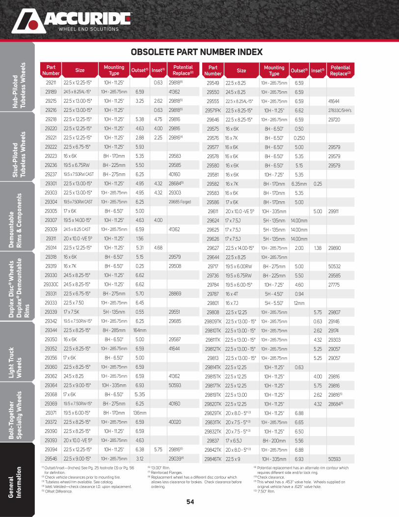
Gen
eral
In
form
atio
nB
olt-
Toge
ther
Sp
ecia
lty
Whe
els
Ligh
t Tru
ck
Whe
els
Dup
lex
Dis
c® W
heel
s D
uple
x® D
emou
ntab
le
Rim
s
Dem
ount
able
Rim
s &
Com
pone
nts
Stud
-Pilo
ted
Tube
less
Whe
els
Hub
-Pilo
ted
Tube
less
Whe
els
54
OBSOLETE PART NUMBER INDEX
(1) Outset/lnset—(Inches) See Pg. 25 footnote (3) or Pg. 56 for defi nition.
(2) Check vehicle clearances prior to mounting tire. (3) Tubeless wheel/rim available. See catalog.(4) Well Welded—check clearance I.D. upon replacement. (5) Offset Difference.
(6) 13.00" Rim.(7) Reinforced Flanges.(8) Replacement wheel has a different disc contour which
allows less clearance for brakes. Check clearance before ordering.
(9) Potential replacement has an alternate rim contour which requires different side and/or lock ring.
(10) Check clearance.(11) This wheel has a .453" valve hole. Wheels supplied on original vehicle have a .625" valve hole.(12) 7.50" Rim.
Part Number
SizeMounting
TypeOutset(1) Inset(1)
Potential Replace(2)
29211 22.5 x 12.25-15° 10H - 11.25" 0.63 29818(6)
29189 24.5 x 8.25AL-15° 10H - 285.75mm 6.59 41362
29215 22.5 x 13.00-15° 10H - 11.25" 3.25 2.62 29818(5)
29216 22.5 x 13.00-15° 10H - 11.25" 0.63 29818(5)
29218 22.5 x 12.25-15° 10H - 11.25" 5.38 4.75 29816
29220 22.5 x 12.25-15° 10H - 11.25" 4.63 4.00 29816
29221 22.5 x 12.25-15° 10H - 11.25" 2.88 2.25 29816(4)
29222 22.5 x 6.75-15° 10H - 11.25" 5.93
29223 16 x 6K 8H - 170mm 5.35 29583
29236 19.5 x 6.75RW 8H - 225mm 5.50 29585
29237 19.5 x 7.50RW CAST 8H - 275mm 6.25 40160
29301 22.5 x 13.00-15° 10H - 11.25" 4.95 4.32 28684(5)
29303 22.5 x 13.00-15° 10H - 285.75mm 4.95 4.32 29303
29304 19.5 x 7.50RW CAST 10H - 285.75mm 6.25 29685 Forged
29305 17 x 6K 8H - 6.50" 5.00
29307 19.5 x 14.00-15° 10H - 11.25" 4.63 4.00
29309 24.5 x 8.25 CAST 10H - 285.75mm 6.59 41362
29311 20 x 10.0 -VE 5º 10H - 11.25" 1.56
29314 22.5 x 12.25-15° 10H - 11.25" 5.31 4.68
29318 16 x 6K 8H - 6.50" 5.15 29579
29319 16 x 7K 8H - 6.50" 0.25 29508
29330 24.5 x 8.25-15° 10H - 11.25" 6.62
29330C 24.5 x 8.25-15° 10H - 11.25" 6.62
29331 22.5 x 6.75-15° 8H - 275mm 5.70 28869
29333 22.5 x 7.50 10H - 285.75mm 6.45
29339 17 x 7.5K 5H - 135mm 0.55 29551
29342 19.5 x 7.50RW-15° 10H - 285.75mm 6.25 29685
29344 22.5 x 8.25-15° 8H - 285mm 164mm
29350 16 x 6K 8H - 6.50" 5.00 29587
29352 22.5 x 8.25-15° 10H - 285.75mm 6.59 41644
29356 17 x 6K 8H - 6.50" 5.00
29360 22.5 x 8.25-15° 10H - 285.75mm 6.59
29362 24.5 x 8.25 10H - 285.75mm 6.59 41362
29364 22.5 x 9.00-15° 10H - 335mm 6.93 50593
29368 17 x 6K 8H - 6.50" 5.35
29369 19.5 x 7.50RW-15° 8H - 275mm 6.25 40160
29371 19.5 x 6.00-15° 8H - 170mm 136mm
29372 22.5 x 8.25-15° 10H - 285.75mm 6.59 40020
29390 22.5 x 8.25-15° 10H - 11.25" 6.59
29393 20 x 10.0 -VE 5º 10H - 285.75mm 4.63
29394 22.5 x 12.25-15° 10H - 11.25" 6.38 5.75 29816(6)
29546 22.5 x 9.00-15° 10H - 285.75mm 3.12 29039(4)
Part Number
SizeMounting
TypeOutset(1) Inset(1)
Potential Replace(2)
29549 22.5 x 8.25 10H - 285.75mm 6.59
29550 24.5 x 8.25 10H - 285.75mm 6.59
29555 22.5 x 8.25AL-15° 10H - 285.75mm 6.59 41644
29571PK 22.5 x 8.25-15° 10H - 11.25" 6.62 27833C/5HH’s
29646 22.5 x 8.25-15° 10H - 285.75mm 6.59 29720
29575 16 x 6K 8H - 6.50" 0.50
29576 16 x 7K 8H - 6.50" 0.250
29577 16 x 6K 8H - 6.50" 5.00 29579
29578 16 x 6K 8H - 6.50" 5.35 29579
29580 16 x 6K 8H - 6.50" 5.15 29579
29581 16 x 6K 10H - 7.25" 5.35
29582 16 x 7K 8H - 170mm 6.35mm 0.25
29583 16 x 6K 8H - 170mm 5.35
29586 17 x 6K 8H - 170mm 5.00
29611 20 x 10.0 -VE 5º 10H - 335mm 5.00 29911
29624 17 x 7.5J 5H - 135mm 14.00mm
29625 17 x 7.5J 5H - 135mm 14.00mm
29626 17 x 7.5J 5H - 135mm 14.00mm
29627 22.5 x 14.00-15° 10H - 285.75mm 2.00 1.38 29890
29644 22.5 x 8.25 10H - 285.75mm
29717 19.5 x 6.00RW 8H - 275mm 5.00 50532
29736 19.5 x 6.75RW 8H - 225mm 5.50 29585
29784 19.5 x 6.00-15° 10H - 7.25" 4.60 27775
29787 16 x 4T 5H - 4.50" 0.94
29801 16 x 7J 5H - 5.50" 12mm
29808 22.5 x 12.25 10H - 285.75mm 5.75 29807
29809TK 22.5 x 13.00 - 15° 10H - 285.75mm 0.63 29146
29810TK 22.5 x 13.00 - 15° 10H - 285.75mm 2.62 29174
29811TK 22.5 x 13.00 - 15° 10H - 285.75mm 4.32 29303
29812TK 22.5 x 13.00 - 15° 10H - 285.75mm 5.25 29057
29813 22.5 x 13.00 - 15° 10H - 285.75mm 5.25 29057
29814TK 22.5 x 12.25 10H - 11.25" 0.63
29815TK 22.5 x 12.25 10H - 11.25" 4.00 29816
29817TK 22.5 x 12.25 10H - 11.25" 5.75 29816
29819TK 22.5 x 13.00 10H - 11.25" 2.62 29816(5)
29820TK 22.5 x 12.25 10H - 11.25" 4.32 28684(5)
29829TK 20 x 8.0 - 5° (3) 10H - 11.25" 6.88
29831TK 20 x 7.5 - 5° (3) 10H - 285.75mm 6.65
29832TK 20 x 7.5 - 5° (3) 10H - 11.25" 6.50
29837 17 x 6.5J 8H - 200mm 5.56
29842TK 20 x 8.0 - 5° (3) 10H - 285.75mm 6.88
29846TK 22.5 x 9 10H - 335mm 6.93 50593
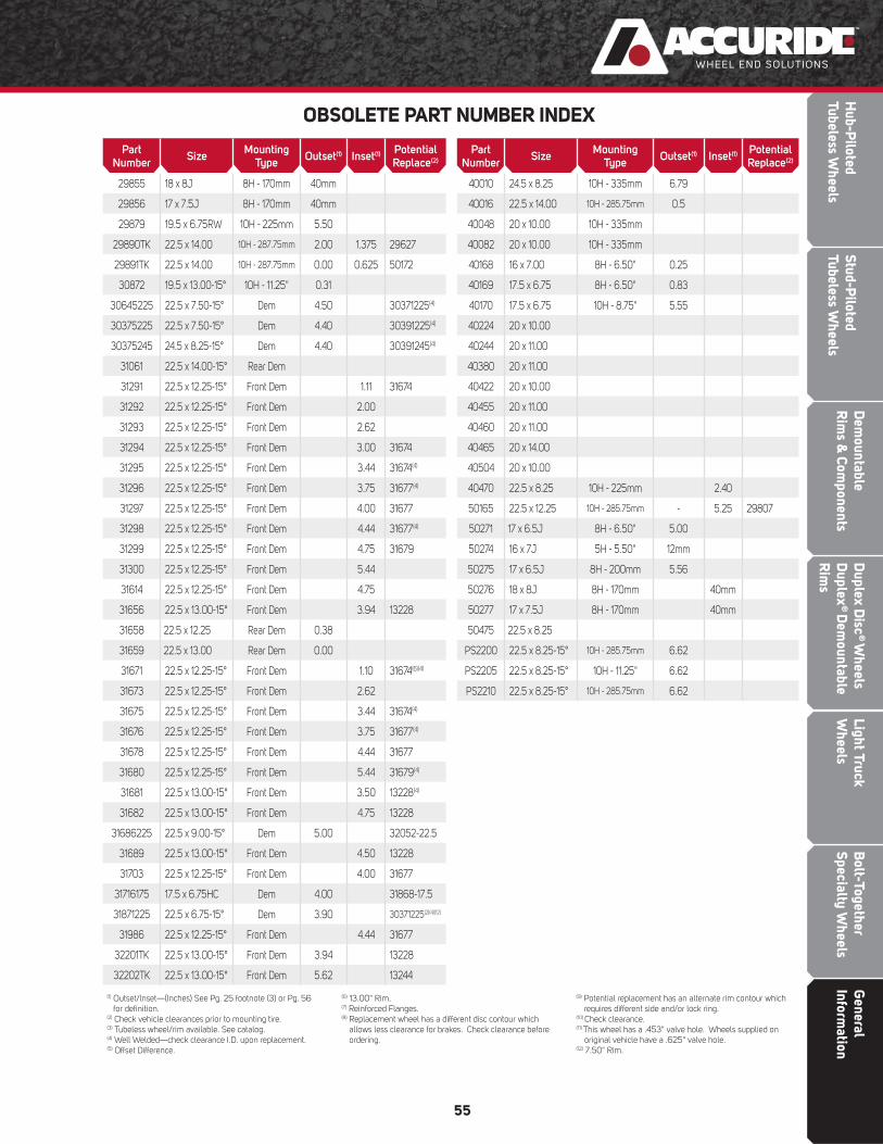
Dem
ountableR
ims &
Components
Bolt-Together
Specialty Wheels
Light Truck W
heelsD
uplex Disc
® W
heels D
uplex®
Dem
ountable R
ims
Stud-Piloted
Tubeless Wheels
Hub-P
ilotedTubeless W
heels
General
Information
55
Part Number
SizeMounting
TypeOutset(1) Inset(1)
Potential Replace(2)
29855 18 x 8J 8H - 170mm 40mm
29856 17 x 7.5J 8H - 170mm 40mm
29879 19.5 x 6.75RW 10H - 225mm 5.50
29890TK 22.5 x 14.00 10H - 287.75mm 2.00 1.375 29627
29891TK 22.5 x 14.00 10H - 287.75mm 0.00 0.625 50172
30872 19.5 x 13.00-15° 10H - 11.25" 0.31
30645225 22.5 x 7.50-15° Dem 4.50 30371225(4)
30375225 22.5 x 7.50-15° Dem 4.40 30391225(4)
30375245 24.5 x 8.25-15° Dem 4.40 30391245(4)
31061 22.5 x 14.00-15° Rear Dem
31291 22.5 x 12.25-15° Front Dem 1.11 31674
31292 22.5 x 12.25-15° Front Dem 2.00
31293 22.5 x 12.25-15° Front Dem 2.62
31294 22.5 x 12.25-15° Front Dem 3.00 31674
31295 22.5 x 12.25-15° Front Dem 3.44 31674(4)
31296 22.5 x 12.25-15° Front Dem 3.75 31677(4)
31297 22.5 x 12.25-15° Front Dem 4.00 31677
31298 22.5 x 12.25-15° Front Dem 4.44 31677(4)
31299 22.5 x 12.25-15° Front Dem 4.75 31679
31300 22.5 x 12.25-15° Front Dem 5.44
31614 22.5 x 12.25-15° Front Dem 4.75
31656 22.5 x 13.00-15° Front Dem 3.94 13228
31658 22.5 x 12.25 Rear Dem 0.38
31659 22.5 x 13.00 Rear Dem 0.00
31671 22.5 x 12.25-15° Front Dem 1.10 31674(6)(4)
31673 22.5 x 12.25-15° Front Dem 2.62
31675 22.5 x 12.25-15° Front Dem 3.44 31674(4)
31676 22.5 x 12.25-15° Front Dem 3.75 31677(4)
31678 22.5 x 12.25-15° Front Dem 4.44 31677
31680 22.5 x 12.25-15° Front Dem 5.44 31679(4)
31681 22.5 x 13.00-15° Front Dem 3.50 13228(4)
31682 22.5 x 13.00-15° Front Dem 4.75 13228
31686225 22.5 x 9.00-15° Dem 5.00 32052-22.5
31689 22.5 x 13.00-15° Front Dem 4.50 13228
31703 22.5 x 12.25-15° Front Dem 4.00 31677
31716175 17.5 x 6.75HC Dem 4.00 31868-17.5
31871225 22.5 x 6.75-15° Dem 3.90 30371225(2)(4)(12)
31986 22.5 x 12.25-15° Front Dem 4.44 31677
32201TK 22.5 x 13.00-15° Front Dem 3.94 13228
32202TK 22.5 x 13.00-15° Front Dem 5.62 13244
OBSOLETE PART NUMBER INDEX
Part Number
SizeMounting
TypeOutset(1) Inset(1)
Potential Replace(2)
40010 24.5 x 8.25 10H - 335mm 6.79
40016 22.5 x 14.00 10H - 285.75mm 0.5
40048 20 x 10.00 10H - 335mm
40082 20 x 10.00 10H - 335mm
40168 16 x 7.00 8H - 6.50" 0.25
40169 17.5 x 6.75 8H - 6.50" 0.83
40170 17.5 x 6.75 10H - 8.75" 5.55
40224 20 x 10.00
40244 20 x 11.00
40380 20 x 11.00
40422 20 x 10.00
40455 20 x 11.00
40460 20 x 11.00
40465 20 x 14.00
40504 20 x 10.00
40470 22.5 x 8.25 10H - 225mm 2.40
50165 22.5 x 12.25 10H - 285.75mm - 5.25 29807
50271 17 x 6.5J 8H - 6.50" 5.00
50274 16 x 7J 5H - 5.50" 12mm
50275 17 x 6.5J 8H - 200mm 5.56
50276 18 x 8J 8H - 170mm 40mm
50277 17 x 7.5J 8H - 170mm 40mm
50475 22.5 x 8.25
PS2200 22.5 x 8.25-15° 10H - 285.75mm 6.62
PS2205 22.5 x 8.25-15° 10H - 11.25" 6.62
PS2210 22.5 x 8.25-15° 10H - 285.75mm 6.62
(1) Outset/lnset—(Inches) See Pg. 25 footnote (3) or Pg. 56 for defi nition.
(2) Check vehicle clearances prior to mounting tire. (3) Tubeless wheel/rim available. See catalog.(4) Well Welded—check clearance I.D. upon replacement. (5) Offset Difference.
(6) 13.00" Rim.(7) Reinforced Flanges.(8) Replacement wheel has a different disc contour which
allows less clearance for brakes. Check clearance before ordering.
(9) Potential replacement has an alternate rim contour which requires different side and/or lock ring.
(10) Check clearance.(11) This wheel has a .453" valve hole. Wheels supplied on original vehicle have a .625" valve hole.(12) 7.50" Rim.
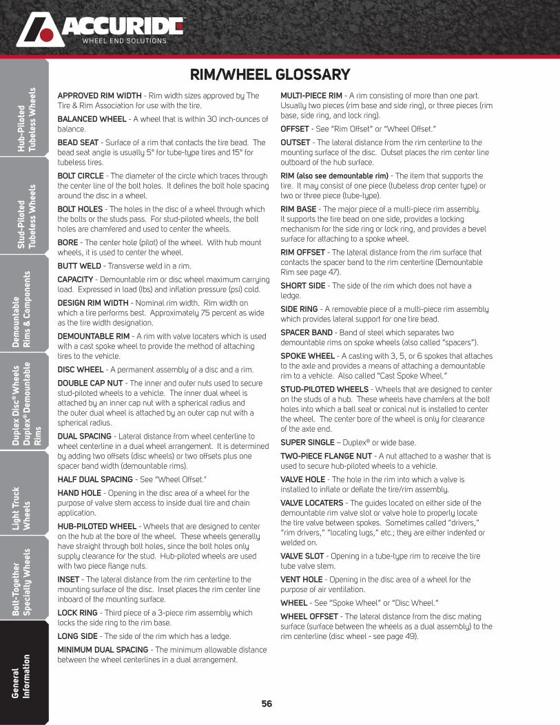
Gen
eral
In
form
atio
nB
olt-
Toge
ther
Sp
ecia
lty
Whe
els
Ligh
t Tru
ck
Whe
els
Dup
lex
Dis
c® W
heel
s D
uple
x® D
emou
ntab
le
Rim
s
Dem
ount
able
Rim
s &
Com
pone
nts
Stud
-Pilo
ted
Tube
less
Whe
els
Hub
-Pilo
ted
Tube
less
Whe
els
56
RIM/WHEEL GLOSSARYAPPROVED RIM WIDTH - Rim width sizes approved by The Tire & Rim Association for use with the tire.
BALANCED WHEEL - A wheel that is within 30 inch-ounces of balance.
BEAD SEAT - Surface of a rim that contacts the tire bead. The bead seat angle is usually 5° for tube-type tires and 15° for tubeless tires.
BOLT CIRCLE - The diameter of the circle which traces through the center line of the bolt holes. It defi nes the bolt hole spacing around the disc in a wheel.
BOLT HOLES - The holes in the disc of a wheel through which the bolts or the studs pass. For stud-piloted wheels, the bolt holes are chamfered and used to center the wheels.
BORE - The center hole (pilot) of the wheel. With hub mount wheels, it is used to center the wheel.
BUTT WELD - Transverse weld in a rim.
CAPACITY - Demountable rim or disc wheel maximum carrying load. Expressed in load (Ibs) and infl ation pressure (psi) cold.
DESIGN RIM WIDTH - Nominal rim width. Rim width on which a tire performs best. Approximately 75 percent as wide as the tire width designation.
DEMOUNTABLE RIM - A rim with valve locaters which is used with a cast spoke wheel to provide the method of attaching tires to the vehicle.
DISC WHEEL - A permanent assembly of a disc and a rim.
DOUBLE CAP NUT - The inner and outer nuts used to secure stud-piloted wheels to a vehicle. The inner dual wheel is attached by an inner cap nut with a spherical radius and the outer dual wheel is attached by an outer cap nut with a spherical radius.
DUAL SPACING - Lateral distance from wheel centerline to wheel centerline in a dual wheel arrangement. It is determined by adding two offsets (disc wheels) or two offsets plus one spacer band width (demountable rims).
HALF DUAL SPACING - See “Wheel Offset."
HAND HOLE - Opening in the disc area of a wheel for the purpose of valve stem access to inside dual tire and chain application.
HUB-PILOTED WHEEL - Wheels that are designed to center on the hub at the bore of the wheel. These wheels generally have straight through bolt holes, since the bolt holes only supply clearance for the stud. Hub-piloted wheels are used with two piece fl ange nuts.
INSET - The lateral distance from the rim centerline to the mounting surface of the disc. Inset places the rim center line inboard of the mounting surface.
LOCK RING - Third piece of a 3-piece rim assembly which locks the side ring to the rim base.
LONG SIDE - The side of the rim which has a ledge.
MINIMUM DUAL SPACING - The minimum allowable distance between the wheel centerlines in a dual arrangement.
MULTI-PIECE RIM - A rim consisting of more than one part. Usually two pieces (rim base and side ring), or three pieces (rim base, side ring, and lock ring).
OFFSET - See “Rim Offset” or “Wheel Offset.”
OUTSET - The lateral distance from the rim centerline to the mounting surface of the disc. Outset places the rim center line outboard of the hub surface.
RIM (also see demountable rim) - The item that supports the tire. It may consist of one piece (tubeless drop center type) or two or three piece (tube-type).
RIM BASE - The major piece of a multi-piece rim assembly. It supports the tire bead on one side, provides a locking mechanism for the side ring or lock ring, and provides a bevel surface for attaching to a spoke wheel.
RIM OFFSET - The lateral distance from the rim surface that contacts the spacer band to the rim centerline (Demountable Rim see page 47).
SHORT SIDE - The side of the rim which does not have a ledge.
SIDE RING - A removable piece of a multi-piece rim assembly which provides lateral support for one tire bead.
SPACER BAND - Band of steel which separates two demountable rims on spoke wheels (also called “spacers”).
SPOKE WHEEL - A casting with 3, 5, or 6 spokes that attaches to the axle and provides a means of attaching a demountable rim to a vehicle. Also called “Cast Spoke Wheel.”
STUD-PILOTED WHEELS - Wheels that are designed to center on the studs of a hub. These wheels have chamfers at the bolt holes into which a ball seat or conical nut is installed to center the wheel. The center bore of the wheel is only for clearance of the axle end.
SUPER SINGLE – Duplex® or wide base.
TWO-PIECE FLANGE NUT - A nut attached to a washer that is used to secure hub-piloted wheels to a vehicle.
VALVE HOLE - The hole in the rim into which a valve is installed to infl ate or defl ate the tire/rim assembly.
VALVE LOCATERS - The guides located on either side of the demountable rim valve slot or valve hole to properly locate the tire valve between spokes. Sometimes called “drivers,” “rim drivers,” “locating lugs,” etc.; they are either indented or welded on.
VALVE SLOT - Opening in a tube-type rim to receive the tire tube valve stem.
VENT HOLE - Opening in the disc area of a wheel for the purpose of air ventilation.
WHEEL - See “Spoke Wheel” or “Disc Wheel.”
WHEEL OFFSET - The lateral distance from the disc mating surface (surface between the wheels as a dual assembly) to the rim centerline (disc wheel - see page 49).