table of contents 1. purpose and scope 2 2. definitions
TRANSCRIPT

COP-0005-PR-Z General Workmanship Standards for Fabricated Materials
Revision D
Page 1 of 22
TABLE OF CONTENTS
1. PURPOSE AND SCOPE .......................................................................................................... 2
2. DEFINITIONS AND ACRONYMS ............................................................................................. 2
3. REFERENCES AND GOVERNING DOCUMENTS ........................................................................ 2
4. RESPONSIBILITIES ................................................................................................................ 3
5. ORDER OF PRECEDENCE ....................................................................................................... 4
6. QUALITY ASSURANCE REQUIREMENTS ................................................................................. 4
7. DRAWINGS .......................................................................................................................... 4
8. MACHINED PARTS ............................................................................................................... 6
9. SHEET METAL PARTS ............................................................................................................ 8
10. WELDING ............................................................................................................................ 9
11. CASTINGS .......................................................................................................................... 10
12. FINISH/PLATING ................................................................................................................ 11
13. ELECTRONIC AND ELECTROMECHANICAL PARTS ................................................................. 12
14. COSMETIC STANDARDS AND SPECIFICATION ...................................................................... 16
15. CLEANING ......................................................................................................................... 21
16. PACKING ........................................................................................................................... 21
17. PMUC-COMPLIANT MATERIALS.......................................................................................... 22
18. ROHS COMPLIANCE ........................................................................................................... 22
19. RECORDS AND DOCUMENTATION - NONE .......................................................................... 22
20. EXCEPTIONS AND SPECIAL CIRCUMSTANCES - NONE ........................................................... 22
COP-0005-PR-Z General Workmanship Standards for Fabricated Materials
Revision D
Page 2 of 22
1. PURPOSE AND SCOPE
1.1. This document establishes a minimum standard for workmanship required of all fabricated materials produced within or outside of Zetec Inc., necessary for the production of the organizations products. The intent is to mitigate quality variations and maintain uniformity among materials fabricated globally.
1.2. This document may be released to suppliers of mechanical, electronic and electromechanical parts (PCBAs, probes, motors, etc.) that are made following Zetec’s design requirements. This document may not be released to suppliers of off-the-shelf parts.
1.3. This document replaces document 01-1005.
2. DEFINITIONS AND ACRONYMS
2.1. Workmanship Knowledge and skill at performing a task that imparts quality to a product
2.2. Industry Standard Generally accepted requirements followed by the NDT industry
2.3. NDT Non-Destructive Testing
2.4. ANSI American National Standards Institute
2.5. ASME American Society of Mechanical Engineers
2.6. ASTM American Society for Testing and Materials
2.7. ASSY Assembly
2.8. BOM Bill of Materials
2.9. CAD Computer Aided Design
2.10. GD&T Geometric Dimensioning and Tolerancing
2.11. S.I. International System of Units
2.12. PMUC Produits et Matériaux Utilisables en Centrale (Products and Materials used in Power Plants)
2.13. US Customary Units Units of measure commonly used by manufacturers in the U.S.A. i.e. inches, mills, etc.
2.14. STD Standard
2.15. GTAW Gas Tungsten Arc Welding
2.16. GMAW Gas Metal Arc Welding
3. REFERENCES AND GOVERNING DOCUMENTS
The following documents are utilized as the basis for this guideline. Equivalent guidelines, used in the country of part manufacturing origin, are also acceptable.
3.1. Federal
3.1.1. A-A-56032 Ink marking, Epoxy Base
3.1.2. FED-STD-H2 Screw-Thread Standards for Federal Services
3.2. Military
3.2.1. MIL-HDBK-60 Threaded Fasteners Tightening to Proper Tension

COP-0005-PR-Z General Workmanship Standards for Fabricated Materials
Revision D
Page 3 of 22
3.2.2. MIL-STD-100G DoD Standard Practice for Engineering Drawings
3.2.3. MIL-STD-12 Abbreviations for use on Drawings, Specifications, Standards and in Technical documents
3.2.4. MIL-STD-889 Dissimilar Metals
3.3. American Industry Standards ANSI/ASME/ASTM
3.3.1. ANSI B4.2 Preferred Metric Limits and Fits
3.3.2. ASME B46.1 Surface Texture, Surface Roughness, Waviness and Lay
3.3.3. ANSI/ASME Y-14.5 Dimensioning & Tolerancing Standard
3.3.4. ASME B1.13M-2005 Metric Screw Threads, M Profile
3.3.5. ANSI/ASME B94.6 Knurls and Knurling
3.3.6. ASTM-A 997 Investment Casting, Surface Acceptance, Visual Examination
3.3.7. ANSI/AWS A2.4 Weld Symbols
3.3.8. AWS WHB-1.9 Welding Handbook
3.3.9. AWS WI 2000 Welding Inspection Handbook
3.3.10. ANSI/AWS C5.5/C5.5M 2003 Gas Tungsten Arc Welding
3.3.11. ANSI/AWS D9.1M/D9.1 2006 Sheet Metal Welding
3.4. Zetec Inc.
3.4.1. ENG-3002-PR-S Engineering Drawing Practices
3.4.2. 10001403 Fastener Captivation Torque Index
3.4.3. 10021176 Knurling Spec Jig, Heavy
3.4.4. PRO-3105-WI-S ESD Handling
3.4.5. IPC-A-600 Class 2 Acceptability of Printed Boards
3.4.6. IPC-A-610 Class 2 Acceptability of Electronic Assemblies
3.4.7. IPC/WHMA-A-620 Class 1 (Unless otherwise specified by drawing and/or Purchase Order), Requirements and Acceptance for Cable and Wire Harness Assemblies
3.4.8. QAP-015S-2015-PR-S Calibration Standard Fabrication and Certification
3.4.9. SCM-3812-FA-S Supplier Codes for Serialized PCBAs
3.4.10. 1004479 Probe Trademark Label Specification.
4. RESPONSIBILITIES
4.1. The Zetec Engineering Department owns this document and is responsible for changes herein. Should a fabrication drawing reference this document, it is the responsibility of Zetec internal manufacturing, and or external contractors producing Zetec components, to abide by the standards herein.
COP-0005-PR-Z General Workmanship Standards for Fabricated Materials
Revision D
Page 4 of 22
5. ORDER OF PRECEDENCE
5.1. The following documents take precedence in the order listed in event of interpretation conflicts. In all cases, the applicable document refers to the latest revision.
• Zetec Inc. Engineering drawings and design documents.
• Zetec Inc. Manufacturing and production documents.
• Zetec Inc. General Drafting and Design Guidelines.
• Industry Standards.
5.2. Units
The S.I. system is the primary unit of measure referred to in this document. Alternatively, US Customary Units may be expressed in the drawings.
6. QUALITY ASSURANCE REQUIREMENTS
6.1. Zetec Quality System
The quality system at Zetec is consistent with ISO Standard 9001:2015 and is described in Zetec Quality documentation.
6.2. Supplier Quality System
The Quality System of Qualified Suppliers will be evaluated against the applicable elements of the appropriate ISO Standard 9001:2015 and the specific requirements of the materials, component, and assemblies involved. Suppliers are qualified in accordance with QAS-0018-PR-Z (Supplier Approval Procedure).
6.2.1. First Article
Supplier Q/A results are to be submitted with first article built to print parts. This requirement continues pending a certification review by Zetec Q/A, followed by supplier notification. Notify Zetec before making additional parts if no confirmation has been received.
7. DRAWINGS
7.1. Drawing Interpretation
Interpretation of dimensions and tolerance requirements shall be in accordance with ANSI/ASME Y- 14.5, and clarified within this document. Unless otherwise specified by drawing and/or Purchase Order, all dimensions are finished dimensions which apply after the part has been heat treated, plated, anodized etc. If not specified on the drawing the manufacturer of the component shall achieve this condition in any way necessary to produce the part, including, but not limited to the following method:
• Masking
• Post-op machining
• Accommodating the plating buildup in the initial machining step

COP-0005-PR-Z General Workmanship Standards for Fabricated Materials
Revision D
Page 5 of 22
7.2. Right Angles
Right angle features depicted on the drawing that are not dimensioned, such as square faces, centerlines, holes, etc. shall be interpreted as a 90° angle with tolerance specified in the drawing title block.
7.3. Unassigned Datum
When features such as diameters are shown on a common axis, but dimensioned without apparent base line or datum, the feature to select as the datum shall be that which provides the worst case tolerance stacking analysis. For example, the datum selected in Figure 1 shall be either feature A1 or A3. When in doubt, contact Zetec for clarification.
Figure 1, Unassigned Datum
7.4. Bolt Circle Spacing
Where the term “equally spaced” is used to define the location of holes or features on bolt circles (B.C.) and similar patterns, the angular tolerance for each hole shall be that specified within the drawing title block.
7.5. Implied symmetry
Features that are drawn around the centerline of another feature do not require dimensional location; symmetry is implied about the centerline and block tolerances apply.
7.6. Inspection Dimensions
All drawings shall conform, and be interpreted, to the dimensioning and tolerancing
requirements of Inspection Dimension. Dimensions enclosed with a bubble , denote a critical dimension per the ENG-3002-PR-S. In addition, any metric dimensions less than 0.1mm (or dimensioned to the 0.0X place) and Standard dimensions less than 0.01 (or dimensioned to the 0.00X place) will be considered critical dimensions by QC and not require any special call outs. The inspection plan for the critical dimensions will be determined by QC as well as governing documents.
7.7. Un-Dimensioned Features
7.7.1. Drawings that are not fully dimensioned shall be controlled by the 3D model. The following note shall apply. When in doubt, contact Zetec for clarification.

COP-0005-PR-Z General Workmanship Standards for Fabricated Materials
Revision D
Page 6 of 22
7.8. All features not directly dimensioned are controlled by the 3d model as shown below.
7.8.1. Drawings shall have, at minimum, the following features dimensioned in the
print:
• All tapped holes
• All precision holes
• All critical to function features
• All features with tolerance requirements tighter than the title block tolerances
• Overall dimensions (may be reference) to aid estimates and quotes
7.8.2. Assumptions that can be made by manufactures for un-dimensioned features:
• Internal pocket radii are considered MAX
• Block tolerances apply to features not governed by the profile tolerance
• Machining lay is uncontrolled
8. MACHINED PARTS
8.1. Lubricants
Machining lubricants and cutting fluids should be aqueous base and of low or no sulfur or chlorine chemistry.
8.2. Burrs
All parts shall be free of sharp projections (burrs) created by the fabrication process, applicable to all features of a part.
8.3. External Corners
Unless otherwise specified by drawing and/or Purchase Order, all external corners and edges shall have a break, defined as removal of material from the corner or edge so as to create a minimum 0.1mm to maximum 0.18 mm or 0.004” to 0.007” chamfer or radius.
8.4. Internal Corners
Unless otherwise specified by drawing and/or Purchase Order, all internal corners or edges shall have a maximum 0.18 mm or 0.007” radius.
8.5. Blending
All intersecting surfaces joined by a radius or chamfer shall make an un-stepped junction to the surface generated by the operation, and shall be applicable to both external and internal surfaces.
8.6. Drilled Holes Depth
The depth of a drilled hole shall be measured from the starting surface to the limit of the full hole diameter penetration and not to the depth of the drill point as shown in Figure 2. The depth is considered minimum unless noted.

COP-0005-PR-Z General Workmanship Standards for Fabricated Materials
Revision D
Page 7 of 22
Figure 2, Drilled Hole Depth
8.7. Threads
Unless noted, all metric threads shall be class 6H internal class 6g external. Unless noted, all Unified Standard threads shall be class 2B internal and 2A external.
8.8. Tap Holes
In no case is it permissible for blind tap holes to be drilled through or to deform in any manner the geometry of any other surfaces. All tap holes shall be countersunk 90° to a diameter equal to, or 0.5mm greater than, the major diameter of the tap. Tap depth is considered a minimum unless noted.
8.9. Knurls
Knurls shall conform to ASME/ANSI B94.6 and noted in conformance to ASME Y14.5-2009
8.10. Countersinks
Countersinks shall be produced with the axis parallel to the hole axis to within ±3°. Countersinks on a radial surface shall be measured across the cord as shown in the below figure.
Figure 3, Countersink on a Curved Surface

COP-0005-PR-Z General Workmanship Standards for Fabricated Materials
Revision D
Page 8 of 22
8.11. Counterbores
Counterbores shall be produced with the axis parallel to the hole axis to within ±3°. Counter bore edges shall be broken in accordance with Section 8.3 (External Corners).
8.12. Surface Roughness
All machined surfaces shall be finished in such a manner as to produce a uniform appearance. Surface finish symbols, or call out, shall be interpreted in accordance to ANSI Y14.36M. Surface finish texture, waviness and lay, shall be interpreted in accordance to ANSI/ASME B46.1. Specified roughness values are the maximum allowed. Finished parts shall be cleaned of all cutting lubricants, discoloration, layout dye, metal particles, dust and dirt. Particular attention shall be given to removing all chips and turning from drilled and tapped holes.
8.13. Probe Bobbin Coil Groove Requirements
Probe Bobbin Coil Groove Corner Radius - Unless otherwise specified by drawing and/or Purchase Order; Grooves in Bobbins shall have sharp corners (max tool radius .003).
Groove surfaces must be smooth, (63 in. or 1.6 m finish or better). See figure below.
Figure 4, Bobbin Coil Groove
9. SHEET METAL PARTS
All conditions described under Section 4, Machined Parts, also applies to sheet metal parts with additional requirements or exceptions as noted in the following.
9.1. Flatness
A minimal degree of warp is allowed for finished sheet metal parts. A flatness tolerance shall apply as listed in the below table.
Table 1, Sheet Metal Flatness Requirement
Part Length, mm [inches] Flatness, mm [inches]
<100 [4] .005 [0.0002] per mm [inch] of length
>100 [4] 0.5 +0.004 [0.02 + 0.00015]per additional mm [inch]of length over 100 [4]
COP-0005-PR-Z General Workmanship Standards for Fabricated Materials
Revision D
Page 9 of 22
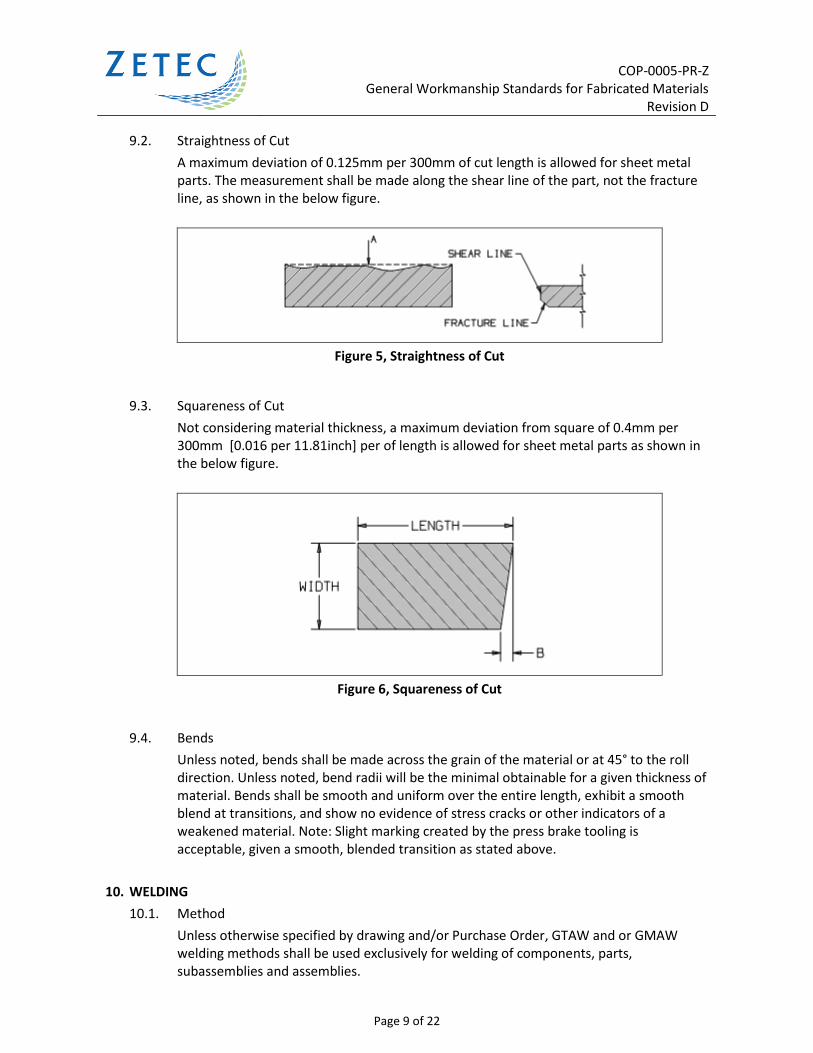
9.2. Straightness of Cut
A maximum deviation of 0.125mm per 300mm of cut length is allowed for sheet metal parts. The measurement shall be made along the shear line of the part, not the fracture line, as shown in the below figure.
Figure 5, Straightness of Cut
9.3. Squareness of Cut
Not considering material thickness, a maximum deviation from square of 0.4mm per 300mm [0.016 per 11.81inch] per of length is allowed for sheet metal parts as shown in the below figure.
Figure 6, Squareness of Cut
9.4. Bends
Unless noted, bends shall be made across the grain of the material or at 45° to the roll direction. Unless noted, bend radii will be the minimal obtainable for a given thickness of material. Bends shall be smooth and uniform over the entire length, exhibit a smooth blend at transitions, and show no evidence of stress cracks or other indicators of a weakened material. Note: Slight marking created by the press brake tooling is acceptable, given a smooth, blended transition as stated above.
10. WELDING
10.1. Method
Unless otherwise specified by drawing and/or Purchase Order, GTAW and or GMAW welding methods shall be used exclusively for welding of components, parts, subassemblies and assemblies.

COP-0005-PR-Z General Workmanship Standards for Fabricated Materials
Revision D
Page 10 of 22
10.2. Filler
Unless otherwise specified by drawing and/or Purchase Order, filler metal if used shall be appropriately selected from the AWS Welding Handbook, taking into account the types of base/parent materials, the welding method being used, and the final application of the end product. Sufficient filler metal shall be used to produce a visually acceptable, structurally and functional weld.
10.3. Pre-Weld Material Preparation
Prior to welding, components shall be cleaned using appropriate methods and materials to ensure the joint is free of particulate, oil, and any other substance that if not removed would impact the weld integrity. Cleaning solutions must not contain ozone depleting chemicals, CFCs, HCFCs, or hydrocarbon based solutions.
10.4. Post-Weld Preparation for Inspection
Prior to visual inspection, welds shall be cleaned to remove all slag and splatter and or other oxides created during the welding process. Cleaning shall be performed carefully, using appropriate methods and materials to prevent existing faults from being obscured. Protective coatings that conceal or which may cause error of inspection, shall not be applied to the weld prior to inspection.
10.5. Post-Weld Inspection
Welds shall be visually inspected to ensure compliance with the weld requirement and fit for the intended service. Inspection shall occur prior to final dressing of the weld. Failure in compliance and or defects in the weld as listed below are cause for rejection.
• Cracks: Cracks are linear with sharp end conditions that tend to grow over the lifetime of the weld.
• Porosity: A cavity in the weld formed by trapped gas during solidification.
• Undercut: A condition in which the base metal has been melted away adjacent to the weld creating a pocket or gouge.
• Overlap: A protrusion of the weld beyond the weld toe or root.
• Underfill: Insufficient filler metal used to adequately fill the weld joint.
• Incomplete Fusion: Insufficient bonding between weld metal and joint interface, or between adjoining weld beads.
• Burn Through: When 100% penetration is achieved, exposing the backside of the weld to the atmosphere such that it is not shielded and oxidizes.
• Arc Strikes: A localized melting of the material caused by false starts of a weld. Arc strikes can provide a crack initiation site.
• Inclusions: Foreign matter trapped inside the weld.
11. CASTINGS
11.1. Draft
Tolerances on cast dimensions do not include draft. When there is a maximum permissible limit for draft, when surfaces must be free of draft, or when the direction of draft is important, the drawing will so note. Otherwise, draft shall be in accordance with industry foundry practice.

COP-0005-PR-Z General Workmanship Standards for Fabricated Materials
Revision D
Page 11 of 22
11.2. Surface Roughness
All external surfaces shall be finished in such a manner as to produce a substantially uniform appearance. Internal surfaces shall be free of excess material and all irregularities shall be carefully blended. Risers, gates, and parting lines shall be removed in a workmanlike manner leaving as little excess material as possible. Surface finishes shall meet ASTM-A 997 standards as shown in the following table.
Table 2, Allowable Surface Roughness for Cast Parts
Process Roughness Average
Sand casting
Perm mold casting
Investment casting
Die casting
Micrometers (m) 50 25 12.5 6.3 3.2 1.6 0.8 0.4 0.2
Microinches ( in.) -2000 -1000 -500 -250 -125 -63 -32 -16 -8
Key
= Average application
= Less frequent application
12. FINISH/PLATING
All plated surfaces shall exhibit visual evidence of plating continuity. Plating must be bonded firmly to the base metal, be smooth and uniform in color, and shall be free from defects such as pits and blisters.
12.1. Painting
All painted parts shall appear smooth and continuous and shall be uniform in color. Painted parts shall be free of runs, sags, orange peel or other such imperfections. Sanding, grinding and other base metal flaws are not acceptable.
12.2. Anodizing
Anodized parts shall conform to the specification indicated in the part drawing and shall appear smooth, continuous and uniform in color. Anodizing chemical composition, process temperature and process time must be uniform for all parts of the same specified anodizing to prevent wide variation in color and quality. Anode contact point will be specified if required in drawing and threads will be masked.
12.3. Silk Screen
Characters and line definition shall be clean, sharp and free of voids. Screen artwork must be approved by Zetec prior to screen preparation.

COP-0005-PR-Z General Workmanship Standards for Fabricated Materials
Revision D
Page 12 of 22
12.4. Laser Marking
Characters and line definition shall appear continuous and without voids. Base material shall not be removed or melted in this process. The surface of the marking shall be smooth and undetected by touch. Note: Laser Marking is defined differently than Laser Etching or Laser Engraving. Marking only discolors the material and does not melt or remove material.
13. ELECTRONIC AND ELECTROMECHANICAL PARTS
NOTE: Where required and to ensure specified measurements and tolerances are maintained, use of Measuring and Test Equipment that has a valid calibration are required. ‘For Reference Only’ (either identified as such or not marked with a valid calibration sticker) measuring devices may be used where the measurements or tolerances are not critical, or required to maintain specific tolerances per applicable specifications, design drawings, etc.
13.1. Cleaning
As part of assembly, calibration and inspection operations, parts and assembled equipment should be cleaned of smudges, loose, spattered, or excess solder or any other foreign material which might detract from the intended operation, function, or appearance of the equipment.
13.2. Cosmetic Appearances
All cosmetic defect/damages shall be evaluated for rework or replacement at the appropriate time so as to avoid disassembly. Internal components of assemblies need not be evaluated for such defects unless problem(s) occurs during troubleshooting or manufacturing on the production line.
13.3. Optical Components
Front panel display glass and windows shall be free of nicks, scratches, foreign material and fingerprints. Remove parts from packaging and handle accordingly. Care should be taken to not place or drag the parts on any surface which can cause damage.
13.4. Threaded Parts or Devices
Screws, nuts and bolts should show no evidence of cross threading, mutilation, or detrimental or hazardous burrs, and should be firmly secured.
13.5. Connector Backshells
Hand tighten until seated. Using soft jaw pliers turn another 1/8 to 1/4 turn.
13.6. Fasteners
Fasteners shall be itemized in the Bill of Material, or part of its own components, specified on the engineering document.
13.7. Countersunk Head Screws
Unless otherwise specified by drawing and/or Purchase Order– Countersunk head screw fasteners shall be visually and physically flush or slightly lower than the surface. Fasteners that are protruding above the surface or unusually ‘countersunk’ shall be evaluated and determined for acceptability. Specific flushness tolerances will be specified on the engineering document.

COP-0005-PR-Z General Workmanship Standards for Fabricated Materials
Revision D
Page 13 of 22
13.8. Screws with Thread-Locking and Retaining Compounds
Screws will be properly identified on Zetec drawings and as a general rule, shall be patch screws.
13.9. Wiring
Wires and cables shall be positioned and/or protected to avoid contact with rough or irregular surfaces and sharp edges so as to avoid damage to conductors and/or adjacent parts.
13.10. Shielding
Shielding on wires and cables should be secured in a manner that will prevent the shielding from contacting or shorting exposed current-carrying parts. The ends of the shielding or braid should be secured to prevent fraying.
13.11. Containment
The harness and cable containment means should be neat in appearance, uniformly applied, and positioned to retain critical form factors and breakout locations. The containment means (lacing, ties, tie wraps, etc.) should not cause the wire or cable insulation to deform such that performance characteristics are adversely affected.
13.12. Insulation
There should be no evidence of burns, abrading, or pinch marks in the insulation that could cause short circuits or leakage.
13.13. Adhesives
Adhesives are substances capable of holding materials together by surface attachment. Adhesive is a general term and includes, among others, cement, glue, and epoxy.
13.13.1. Application -- Care should be taken to avoid starved joints, which are the results of either absorption of adhesive by a porous material, poor application, inadequate coverage, or excessive pressure. Where one or both of the adherents are porous, successive thin coats of adhesive should be applied to completely seal the surface, and each coat should be dry before the next coat is applied. In general, the thicker the adhesive layers the lower the shear resistance, but the higher the strength to impact and peeling.
13.13.2. Excessive adhesive -- Adhesive that is visible and creates a formed feature by overflow shall be smoothed out and/or cleaned off part(s). Such overflow should be evaluated to determine its affect to the product’s performance. (Example: Bobbins require a smooth, even surface and excess overflow could affect the performance of the bobbin probe.
13.14. Electrostatic Discharge (ESD) Protection
Always use appropriate ESD equipment when handling ESD sensitive products. See Zetec Procedure PRO-3105-WI-S ESD Handling.
13.15. Electronic Assemblies
For Electronic Assembly acceptability criteria, refer to industry standard IPC-A-610, Class 2, unless otherwise specified by drawing and/or Purchase Order.
13.16. Printed Circuit Boards
13.17. For Printed Circuit Boards acceptability criteria, use industry standards IPC-A-600, Class 2and IPC-A-610, Class 2, unless otherwise specified by drawing and/or Purchase Order.

COP-0005-PR-Z General Workmanship Standards for Fabricated Materials
Revision D
Page 14 of 22
13.18. Serialization
13.18.1. Serial number labels shall be applied to PCBAs if specified in the drawings.
13.18.2. Serial number labels shall be applied to areas where they will not interfere with the functionality of the PCBA. Preferably, labels are to be placed adjacent to the item number labels.
13.18.3. Serial numbers shall be formatted as follows:
SYYWWNN Rev R • S = Supplier code (Refer to the Supplier Codes for Serialized PCBs table)
SCM-3812-FA-S.
• YY = Calendar year
• WW = Calendar week (01-52)
• NN = Sequential number from 01 to 99. The sequence returns to 01 every month.
• R = Revision of the PCBA
Example: A180702 Rev B
13.19. Probe Labels
13.19.1. Probes are labeled at the Finished Good Assembly level at the location specified in the drawing and including information specified (in general terms) in the drawing.
13.19.2. When the drawing specifies to Laser Engrave information as listed below, use the format shown in Table 3.
Table 3, Engraving
INFORMATION FORMAT
Zetec, Inc. ZETEC, INC.
Part Number or PN 12345678 or ABCD-XXX
(Where 12345678 is the 8-digit part number or a family based number)
Description XXXX-XXX-XXXXX
(Where XXXXX-XXX-XXX is the description as shown on the Shop Order)
Serial Number or SN SN YYYYYY
(Where YYYYY is the 6-digit numeric serial number)
Example: ZETEC, INC.
10027290
ZBPS-AC3-E00.520-LF-ACA0000
SN 546102

COP-0005-PR-Z General Workmanship Standards for Fabricated Materials
Revision D
Page 15 of 22
Note: X-Probe® array probes, ELFiD™ Bobbin probes, Probe heads with +Point™ coils and MRPC® Motor units require trademark labels. The trademark labels will be positioned in accordance with document 1004479, Probe Trademark Label Specification.
13.20. Calibration Standards Labels
See QAS-3015-PR-S, Calibration Standard Fabrication and Certification
13.21. Harness and Cable Assemblies
See IPC/WHMA-A-620 - Requirement and Acceptance for Cable and Wire Harness Assemblies
13.22. Cable Labels
Assembly Labels are to be identified on the engineering document and shall include, but are not limited to:
• Item/Part Number and BOM (Bill Of Materials) Revision
• Item/Part Description
13.23. Termination Label
Termination labels are identified on the engineering document and include, but are not limited to appropriate identification e.g., “Pole Motor Control”.
13.24. Label Marking
Unless otherwise specified by drawing and/or Purchase Order, assembly cable labels are printed with contrasting ink (usually black) onto specified tubing. Text should be legible with the unaided eye.
13.24.1. Only specified Brady “PermaSleeve Heat-Shrink Polyolefin” series labels are to be used for cables. These labels should be called out on the engineering document. Other label materials require written approval from Zetec, Inc.
13.24.2. General Location of Assembly Label(s) -- The general locations of the assembly labels are approximately 1 ±1/2 inch behind the back shell of the connector or rubber boot when space permits.
Figure 7, Label Locations

COP-0005-PR-Z General Workmanship Standards for Fabricated Materials
Revision D
Page 16 of 22
13.25. Sleeving Requirements
The following items shall be covered with suitable heat shrink as specified on the engineering document.
• Solder Cup connections
• Exposed Drain Wire
• Splices where soldered
13.26. Acceptable Adhesives for Cable and Wire Harness Assemblies
The following adhesives are currently approved for use on Cables and Harnesses and are to be shown on the engineering document for approximate locations. Follow general standard practice for applications, paragraph 2.10 unless otherwise specified by drawing and/or Purchase Order.
• Green Thread Locker -- Loctite 290 (P/N 29021). Use on screws at the Strain Relief. Apply Thread Locker to threads on the end of screws after tightening.
• Red Thread Locker -- Loctite 271 (P/N 27121). Use on screw threads connecting Back Shells to Connectors and Clamps to “Body” or “Middle Sections”.
• Blue Thread Locker -- Loctite 243 (P/N 240079) is nuclear grade and is generally applied to all Lemo style connectors at the thread of the connector and back shell.
14. COSMETIC STANDARDS AND SPECIFICATION
14.1. Finished parts shall be inspected and conform to a degree of cosmetic acceptability. Criteria covered in this section applies to unpainted parts. Cosmetic defects, though acceptable to a degree as classified below, shall not bring a part outside its original tolerance requirement. Cosmetic requirement is categorized as Class A through Class E as defined in the following table.
Table 4, Cosmetic Classification
Class A Always Viewed
Class B Usually Viewed
Class C Seldom Viewed (viewed through window)
Class D Seldom Viewed (viewed when covers are removed)
Class E Not Visible
14.2. The inclusion of cosmetic requirements on a part drawing is an Engineering responsibility. If no class reference is noted then the requirement shall be Class D for inspection purposes.

COP-0005-PR-Z General Workmanship Standards for Fabricated Materials
Revision D
Page 17 of 22
14.3. Cosmetic Inspection
For inspection, lighting shall be uniform, non-directional illumination between 80 and 150 foot-candles or lumen 861-16, Cool white light. Magnification shall not be used to inspect. Inspectors shall have 20/20, or J1 equivalent, vision unaided or corrected. The supplier is responsible for having a process in place to ensure vision requirement. Initial cosmetic assessment of parts is based on a 300mm square (maximum) viewing surface and shall be performed using the Time and Distance inspection process as shown in the table below.
Table 5, Cosmetic Inspection Method
Variable Class A-B Class C-D Class E
Viewing Position
Viewing Distance 450mm 450mm 600mm
Viewing Time 10 seconds 5 seconds 3 seconds
Lighting Front Front Front
Angle 0° to 45° 0° 0°
14.4. Cosmetic Inspection Specification - Machined Parts
The table below lists flaws typically found on machined parts. This table constitutes the reference standard of cosmetic acceptability. The total number of allowable mixed flaws shall not exceed the limit specified for the flaw with the largest allowable quantity limit.
Table 6, Defect Classification for Machined Parts
Defect Class A Class B Class C Class D Class E
Discoloration (Maximum)
None One Diameter, 3mm[0.12 inch]
Two Diameter, 9mm [0.35 inch]
Two Diameter, 25mm [0.98 inch]
No cosmetic criteria
Scratches (Maximum)
None One 0.03mm x 6mm [0.001 x 0.24 inch] long
Two 0.03mm x 25mm [0.001 x 0.098 inch] long
Two 0.03mm x 100mm [0.001 x 3.94 inch] long
No cosmetic criteria
Depressions, Protrusions & Specks (Max)
None One Diameter, 1mm [0.04inch]
One Diameter, 3mm [0.12inch]
Two Diameter, 6mm [0.24inch]
No cosmetic criteria

COP-0005-PR-Z General Workmanship Standards for Fabricated Materials
Revision D
Page 18 of 22
14.5. Cosmetic Inspection Specification - Sheet Metal Parts
The table below lists flaws typically found on sheet metal parts. This table constitutes the reference standard of cosmetic acceptability. The total number of allowable mixed flaws shall not exceed the limit specified for the flaw with the largest allowable quantity limit.
Table 7, Defect Classification for Sheet Metal Parts
Defect Class A Class B Class C Class D Class E
Cracks (Maximum)
None None Four 1.5mm
[0.059 inch] long
Four 3mm [0.12inch] long
No cosmetic criteria
Discoloration (Maximum)
None Two Diameter, 0.5mm
[0.02 inch]
Two Diameter, 2mm
[0.08 inch]
Four Diameter, 3mm
[0.12inch]
No cosmetic criteria
Fracturing (Maximum)
None One 1.5mm [0.059 inch] long
Four 1.5mm [0.059 inch] long
Four 3mm [0.12 inch] long
No cosmetic criteria
Depressions, Protrusions & Specks (Maximum)
None One Diameter, 0.5mm
[0.02 inch]
Two Diameter, 1mm
[0.04 inch]
Two Diameter, 1.5mm
[0.059 inch]
No cosmetic criteria
Scratches (Maximum)
One 0.1mm x 3mm [0.04 x 0.12 inch] long
Two 0.1mm x 20mm [0.04 x 0.79 inch] long
Two 0.2mm x 75mm [0.08 x 2.95 inch] long
Three 0.3mm x 100mm [0.12 x 3.94 inch] long
No cosmetic criteria

COP-0005-PR-Z General Workmanship Standards for Fabricated Materials
Revision D
Page 19 of 22
14.6. Cosmetic Inspection Specification-CAST PARTS
The table below lists flaws typically found on cast parts. This table constitutes the reference standard of cosmetic acceptability. The total number of allowable mixed flaws shall not exceed the limit specified for the flaw with the largest allowable quantity limit.
Table 8, Defect Classification for Cast Parts
Defect Class A Class B Class C Class D Class E
Growth (Maximum)
N/A None One Diameter, 1.5mm [0.059
inch]
Two Diameter, 3mm [0.12 inch]
No cosmetic criteria
Heat Checking (Maximum)
N/A Two, 0.2mm [.008 inch] Deep
Two, 0.5mm [0.02 inch] Deep
Four, 1mm [0.04 inch] Deep
No cosmetic criteria
Porosity (gas holes) (Maximum)
N/A Two Diameter, 0.5mm [0.02
inch]
Six Diameter, 1mm [0.04 inch]
Eight Diameter, 2mm [0.08 inch]
No cosmetic criteria
Depressions, Protrusions & Specks (Maximum)
N/A Two Diameter, 0.5mm [0.02
inch]
Six Diameter, 1mm [0.04 inch]
Eight Diameter, 2mm [0.08 inch]
No cosmetic criteria
Scratches & Sinks (Maximum)
N/A Two 0.3mm x 1mm long
[0.12 x 0.04 inch]
Four 0.5mm x 3mm long
[0.02 x 0.12 inch]
Four 0.5mm x 7mm long
[0.12 x 0.28 inch]
No cosmetic criteria
14.7. Cosmetic Inspection Specification – SEAMLESS TUBING
The table below lists flaws typically found on seamless tubing. This table constitutes the reference standard of cosmetic acceptability.
Table 9, Defect Classification
Defect Class A Class B Class C Class D Class E
Discoloration (Maximum)
None None None None No cosmetic criteria
Scratches (Maximum)
None One 0.03mm x 6mm
[0.001 x 0.24 inch] long
Two 0.03mm x 25mm
[0.001 x 0.098 inch] long
Two 0.03mm x 100mm
[0.001 x 3.94 inch] long
No cosmetic criteria
Depressions and Protrusions
None None None None No cosmetic criteria
COP-0005-PR-Z General Workmanship Standards for Fabricated Materials
Revision D
Page 20 of 22
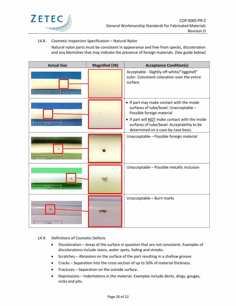
14.8. Cosmetic Inspection Specification – Natural Nylon
Natural nylon parts must be consistent in appearance and free from specks, discoloration and any blemishes that may indicate the presence of foreign materials. (See guide below)
Actual Size Magnified (3X) Acceptance Condition(s)
Acceptable - Slightly off-white/”eggshell” color. Consistent coloration over the entire surface
• If part may make contact with the inside surfaces of tube/bowl: Unacceptable – Possible foreign material
• If part will NOT make contact with the inside surfaces of tube/bowl: Acceptability to be determined on a case-by-case basis.
Unacceptable – Possible foreign material
Unacceptable – Possible metallic inclusion
Unacceptable – Burn marks
14.9. Definitions of Cosmetic Defects
• Discoloration – Areas of the surface in question that are not consistent. Examples of discolorations include stains, water spots, fading and streaks.
• Scratches – Abrasions on the surface of the part resulting in a shallow groove.
• Cracks – Separation into the cross section of up to 50% of material thickness.
• Fractures – Separation on the outside surface.
• Depressions – Indentations in the material. Examples include dents, dings, gouges, nicks and pits.
COP-0005-PR-Z General Workmanship Standards for Fabricated Materials
Revision D
Page 21 of 22
• Protrusions – A raised area on a surface. Examples include blisters, bumps, ridges and bubbles.
• Specks – Small particles that are stuck to the surface or entrapped by the finished coating.
• Inclusions – Foreign material that has been trapped in the base material. (None Allowed)
• Cold Shuts - A cast pouring defect that occurs when two fronts of molten material do not fuse, creating a seam. (None Allowed)
• Misruns - A cast pouring defect that occurs when molten metal does not fill portions of the mold cavity, creating a void. (None Allowed)
• Gas Holes – Porosity in a cast part that occurs when gas is trapped in the molten material and remains as it cools.
• Heat Checking – Fine cracks, fins or veins in a cast part.
• Growth – Expansion of a cast part as it ages.
• Sink – A depression in a cast part caused by abnormal shrinkage during cooling.
15. CLEANING
15.1. All parts shall be cleaned prior to packaging such that all processing contamination has been removed.. Parts which are not fully dry may stain during a long transport. Stained and or dirty and rusty parts shall be rejected.
15.2. A suggested cleaning procedure is as follows:
• Scrub all areas using an appropriate cleaner and sponge to remove lubricants and coolants.
• Ensure all surfaces, tapped holes, bores, etc. are free of lubricant, dirt, debris or rust.
• Fully rinse the part with clean, warm water.
• Dry all surfaces using compressed air.
• Wipe parts with a lint free cloth.
• Un-plated ferric metals must be thinly coated with an easy to remove, water based anti-rust compound or spray.
16. PACKING
16.1. Parts must arrive at their destination in the same condition as they left the supplier. The correct packaging method must be used based on part material, size and weight, such that parts are well protected from the outside environment and or any damage which may occur during transport.
16.2. A suggested cleaning procedure is as follows:
• Wrap parts individually in foam.
• Place the individual parts in a poly bag.
• The poly bag must have a typed label listing the part number, description, revision and supplier name.

COP-0005-PR-Z General Workmanship Standards for Fabricated Materials
Revision D
Page 22 of 22
• Place the wrapped part or parts in a box with additional poly bag and or bubble wrap to fill void spaces such that shifting does not occur and to prevent part to part contact.
16.3. NO PACKING POPCORN ALLOWED.
17. PMUC-COMPLIANT MATERIALS
17.1. Parts that require PMUC compliance must be certified to PMUC prior to delivery to Zetec.
17.2. The part number and lot number on the supplier’s report must match the part number and lot number on the chemical lab’s certificate. If there are multiple numbers (e.g., lot number and batch number), the number to be used should be the one on the certificate.
17.3. If the certificate number is known by the supplier, the certificate number should be noted on the supplier’s report.
18. ROHS COMPLIANCE
All newly designed product components will need to meet RoHS compliance unless otherwise stated.
19. RECORDS AND DOCUMENTATION - NONE
20. EXCEPTIONS AND SPECIAL CIRCUMSTANCES - NONE