t80xr electric shower
TRANSCRIPT

INSTALLERS PLEASE NOTE THESE INSTRUCTIONS ARE TO BE LEFT WITH THE USER
2180455A April 2005
Installation andoperating
instructions
T80xrelectricshower
T80xr
CONTENTS Page
Important safety information 1
Introduction 2
Specifications 2
Advice to users 2
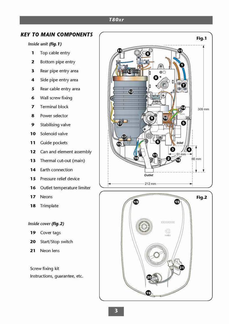
Key to main components 3
Electrical requirements 4 − 5
Water requirements 6
Siting of the shower 7
Fitting the shower to the wall 8 − 9
Plumbing connections 10
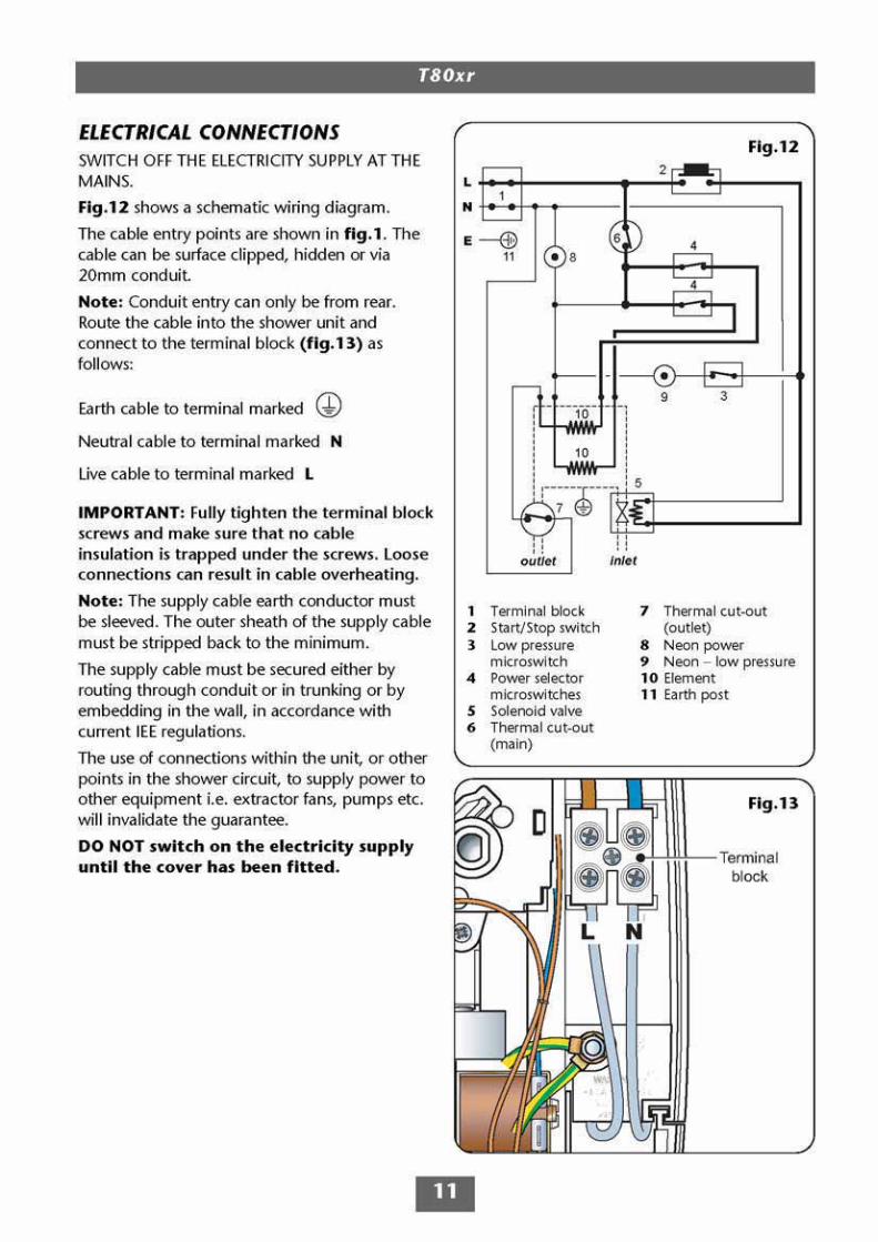
Electrical connections 11
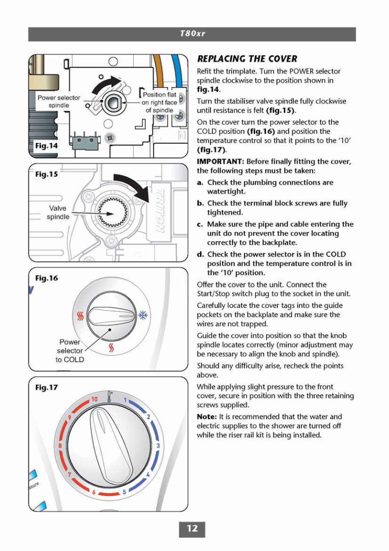
Replacing the cover 12
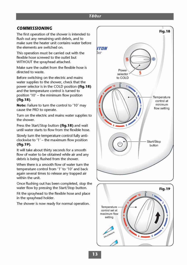
Commissioning 13
Operating the shower 14 − 15
Operating functions 16
Cleaning 16
Instructions for installers and serviceengineers only 17
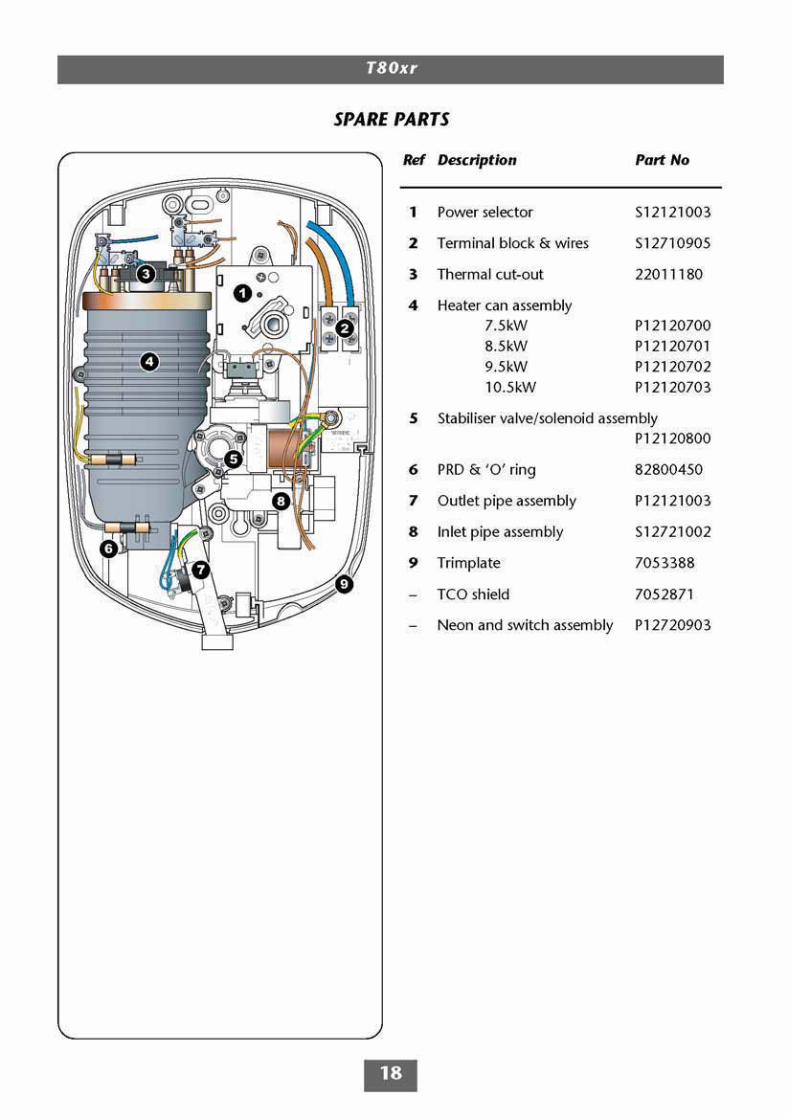
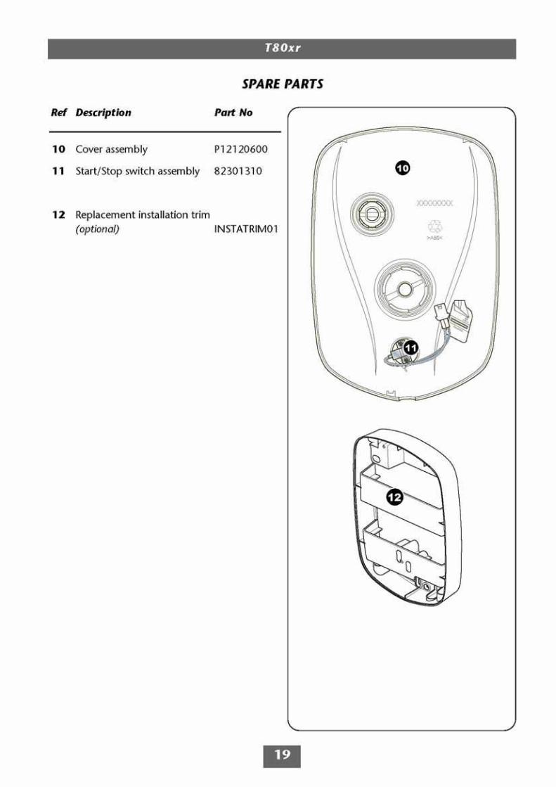
Spare parts 18 − 19
Fault finding 20 − 21
Guarantee, service policy, etc. rear cover
To check the product suitability for commercial and multiple installations, please contactTriton’s specification advisory service before installation.
Telephone: +44 (0) 24 7632 5491Facsimile: +44 (0) 24 7632 4564
E mail: [email protected]
1
T80xr
1 GENERAL1.1 Isolate the electrical and water supplies before
removing the cover.1.2 Read all of these instructions and retain them
for later use.1.3 DO NOT take risks with plumbing or electrical
equipment.1.4 Isolate electrical and water supplies BEFORE
proceeding with the installation.1.5 The unit must be mounted onto the finished
wall surface (on top of the tiles). DO NOT tileup to unit after fixing to wall.
1.6 Contact Customer Service (see back page), ifany of the following occur:a) If it is intended to operate the shower atpressures above the maximum or below theminimum stated.b) If the unit shows a distinct change inperformance.c) If the shower is frozen.
1.7 If it is intended to operate the shower in areasof hard water (above 200 ppm temporaryhardness), a scale inhibitor may have to befitted. For advice on the Triton Scale Inhibitor,contact Triton Customer Service.
1.8 The sprayplate and cartridge must be cleanedregularly with descalent to remove scale anddebris, otherwise restrictions to the flow onthe outlet of the unit will result in highertemperatures and could also cause thePressure Relief Device in unit to operate.
1.9 This product is not suitable for mounting intosteam rooms or steam cubicles.
2 PLUMBING2.1 The plumbing installation must comply with
Water Regulations, Building Regulations or anyparticular regulations as specified by LocalWater Company or Water Undertakers andshould be in accordance with BS 6700.
2.2 The supply pipe must be flushed to clear debrisbefore connecting to the shower unit.
2.3 DO NOT solder pipes or fittings within
300mm of the shower appliance, as heattransfer can damage components.
2.4 DO NOT fit any form of outlet flow control asthe outlet acts as a vent for the heater can.
2.5 DO NOT use excessive force when makingconnections to the flexible hose or sprayhead,finger tight is sufficient.
2.6 All plumbing connections MUST be completedBEFORE making the electrical connections.
3 ELECTRICAL3.1 The installation must comply with BS 7671
‘Requirements for electrical installations’ (IEEwiring regulations), building regulations orany particular regulations as specified by thelocal Electrical Supply Company.
3.2 This appliance MUST be earthed.3.3 In accordance with ‘The Plugs and Sockets etc.
(Safety) Regulations 1994’, this appliance isintended to be permanently connected to thefixed wiring of the electrical mains system.
3.4 Make sure all electrical connections are tightto prevent overheating.
3.5 Fuses DO NOT give personal protectionagainst electric shock.
3.6 To enhance electrical safety a 30mA residualcurrent device (RCD) should be installed in allUK electric and pumped shower circuits. Thismay be part of the consumer unit or aseparate unit.
3.7 Switch the unit off immediately at the isolatingswitch if water ceases to flow during use.
3.8 Other electrical equipment i.e. extractor fans,pumps must not be connected to the circuitswithin the unit.
3.9 Switch off the unit at the isolating switchwhen not in use. This is a safety procedurerecommended with all electrical appliances.
3.10 As with all electrical appliances it isrecommended to have the shower andinstallation checked at least every two years bya competent electrician to make sure there isno deterioration due to age and usage.
PLEASE READ THIS IMPORTANT SAFETY INFORMATION
Products manufactured by Triton are safe and without risk provided they are installed, used andmaintained in good working order in accordance with our instructions and recommendations.DO NOT operate shower if frozen, or suspected of being frozen. It must thaw out before using.DO NOT operate the unit if the sprayhead or spray hose becomes damaged.DO NOT restrict flow out of the shower by placing sprayhead in direct contact with your body.DO NOT operate the shower if water ceases to flow during use or if water has entered inside theunit because of an incorrectly fitted cover.WARNING: If restarting the shower immediately after stopping, be aware that a slug ofhot water will be expelled for the first few seconds.

T80xr
2
INTRODUCTIONThis book contains all the necessary fitting andoperating instructions for your Triton T80xrelectric shower. Please read them carefully.
The shower installation must be carried out by asuitably qualified person and in the sequence ofthis instruction book.
Care taken during the installation will provide along, trouble-free life from your shower.
SPECIFICATIONSElectricalNominal power Nominal powerrating at 240V rating at 230V7.5kW – (32A MCB rating) 6.9kW – (32A MCB rating)8.5kW – (40A MCB rating) 7.9kW – (40A MCB rating)9.5kW – (40A MCB rating) 8.7kW – (40A MCB rating)10.5kW – (45A MCB rating) 9.6kW – (45A MCB rating)
WaterInlet connection – 15mm diameter.Outlet connection – ½” BSP male thread.
Entry PointsWater – bottom, back or right-hand side entry.Cable – top or back.
MaterialsBackplate, cover, controls, sprayhead – ABS.Sprayplate – Acetal.Elements – Minerally insulated corrosion resistantmetal sheathing.
DimensionsHeight − 309mmWidth − 212mmDepth − 95mm
Standards and ApprovalsSplashproof rating IPX4.
Complies with the requirements of currentBritish and European safety standards forhousehold and similar electrical appliances.
Complies with requirements of the BritishElectrotechnical Approvals Board (BEAB).
Meets with Compliance with EuropeanCommunity Directives (CE).
ADVICE TO USERS
The following points will help you understandhow the shower operates:
a The electric heating elements operate at aconstant rate at your chosen power setting. It is therate of the water passing through the heater canwhich determines the water temperature. (Theslower the flow, the hotter the water becomes; thefaster the flow, the cooler the water).
b During winter the mains water supply will becooler than in the summer, so the flow rate willvary between seasons at any one temperaturesetting. At different times of the year you mayhave to adjust the position of the temperaturecontrol to maintain your desired temperaturesetting.
c The stabiliser valve minimises variations inshower temperature during mains waterpressure changes. If changes in showertemperature are experienced during normal use,it will most likely be caused by the waterpressure falling near to or below the minimumlevel. The drop in pressure may be due to waterbeing drawn off at other points in the housewhilst the shower is in use. If pressure dropsappreciably below the minimum, the heatingelements will automatically cut out.
If ever the water becomes too hot and youcannot obtain cooler water, first check that thesprayplate in the sprayhead has not becomeblocked.
DO NOT place items such as soap or shampoobottles on top of the unit. Liquid could seepthrough the joint between the cover andbackplate, and possibly damage the sealingrubber.
IMPORTANT: When first installed the unitwill be empty. It is essential the unitshould contain water before the elementsare switched on. It is vital that thecommissioning procedure is followed.Failure to carry out this operation willresult in damage to the unit and willinvalidate the guarantee.
Due to continuous improvement and updating,specification may be altered without prior notice.
Replacement parts can be ordered from CustomerService. See ‘spare parts’ for details and part numbers.
T80xr
4
ELECTRICAL REQUIREMENTS
The installation, supply cable and circuitprotection must conform with BS7671 (IEEwiring regulations) and be sufficient for theamperage required.
The following notes are for guidance only:
1 The shower must only be connected to a230-240V ac supply. If you are installing ashower with a kilowatt rating above 9kW,it is advisable to contact the localelectricity supply company.
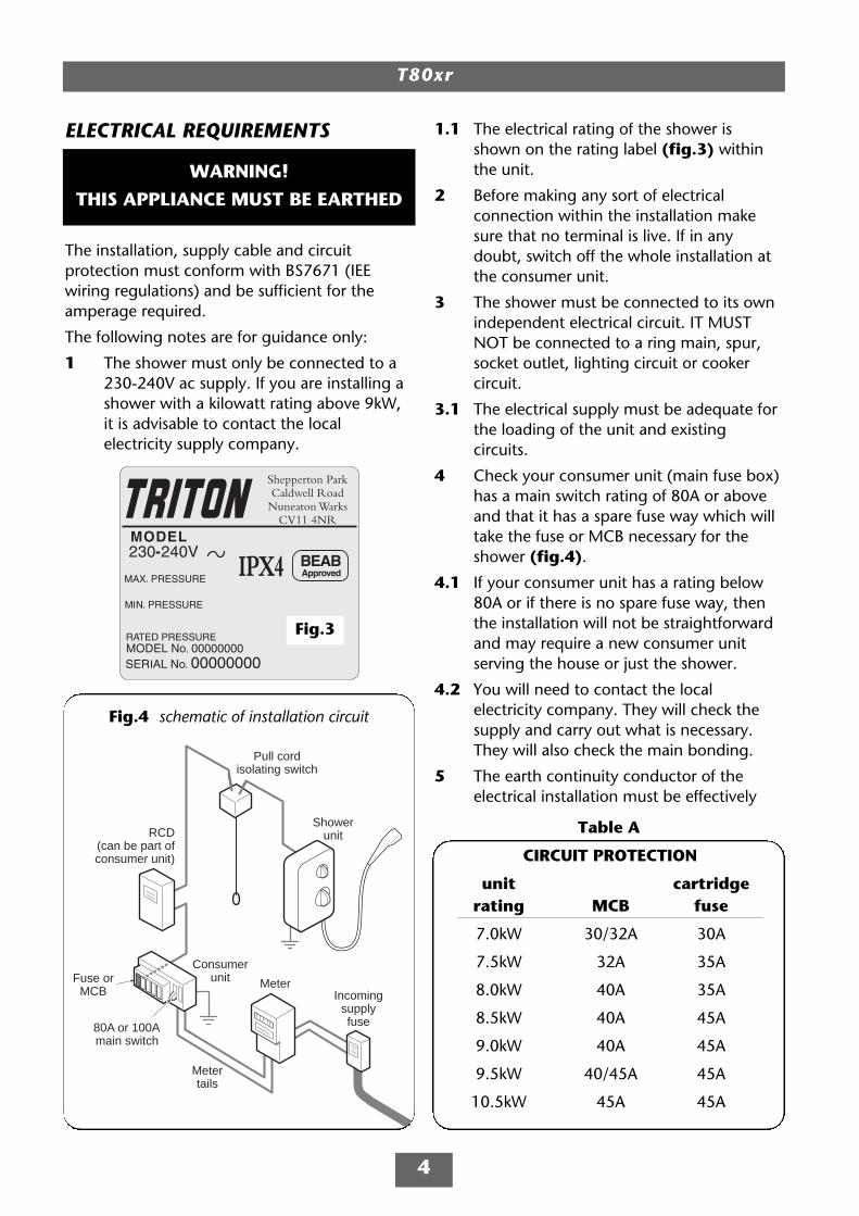
1.1 The electrical rating of the shower isshown on the rating label (fig.3) withinthe unit.
2 Before making any sort of electricalconnection within the installation makesure that no terminal is live. If in anydoubt, switch off the whole installation atthe consumer unit.
3 The shower must be connected to its ownindependent electrical circuit. IT MUSTNOT be connected to a ring main, spur,socket outlet, lighting circuit or cookercircuit.
3.1 The electrical supply must be adequate forthe loading of the unit and existingcircuits.
4 Check your consumer unit (main fuse box)has a main switch rating of 80A or aboveand that it has a spare fuse way which willtake the fuse or MCB necessary for theshower (fig.4).
4.1 If your consumer unit has a rating below80A or if there is no spare fuse way, thenthe installation will not be straightforwardand may require a new consumer unitserving the house or just the shower.
4.2 You will need to contact the localelectricity company. They will check thesupply and carry out what is necessary.They will also check the main bonding.
5 The earth continuity conductor of theelectrical installation must be effectively
MeterIncoming
supplyfuse
Metertails
Consumerunit
Pull cordisolating switch
Showerunit
Fuse orMCB
RCD(can be part ofconsumer unit)
80A or 100Amain switch
Fig.4 schematic of installation circuit
Table A
CIRCUIT PROTECTION
unit cartridgerating MCB fuse
7.0kW 30/32A 30A
7.5kW 32A 35A
8.0kW 40A 35A
8.5kW 40A 45A
9.0kW 40A 45A
9.5kW 40/45A 45A
10.5kW 45A 45A
Fig.3
WARNING!
THIS APPLIANCE MUST BE EARTHED
T80xr
5
connected electrically to all exposed metalparts of other appliances and services inthe room in which the shower is to beinstalled, to conform to current IEEregulations.
5.1 All exposed metallic parts in the bathroommust be bonded together using a cable ofat least 4mm2 cross sectional area. Theseparts include metal baths, radiators, waterpipes, taps and waste fittings.
6 For close circuit protection DO NOT use arewireable fuse. Instead use a suitablyrated miniature circuit breaker (MCB) orcartridge fuse (see table A).
6.1 In the interest of electrical safety a 30mAresidual current device (RCD) should beinstalled in all UK electric and pumpedshower circuits. This may be part of theconsumer unit or a separate unit.
7 A 45 amp double pole isolating switchwith a minimum contact gap of 3mm inboth poles must be incorporated in thecircuit.
7.1 It must have a mechanical indicatorshowing when the switch is in the OFFposition, and the wiring must beconnected to the switch without the use ofa plug or socket outlet.
7.2 The switch must be accessible and clearlyidentifiable, but out of reach of a person
using a fixed bath or shower, except forthe cord of a cord operated switch, andshould be placed so that it is not possibleto touch the switch body while standing ina bath or shower cubicle. It should bereadily accessible to switch off after usingthe shower.
8 Where shower cubicles are located in anyrooms other than bathrooms, all socketoutlets in those rooms must be protectedby a 30mA RCD.
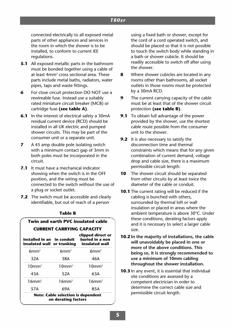
9 The current carrying capacity of the cablemust be at least that of the shower circuitprotection (see table B).
9.1 To obtain full advantage of the powerprovided by the shower, use the shortestcable route possible from the consumerunit to the shower.
9.2 It is also necessary to satisfy thedisconnection time and thermalconstraints which means that for any givencombination of current demand, voltagedrop and cable size, there is a maximumpermissible circuit length.
10 The shower circuit should be separatedfrom other circuits by at least twice thediameter of the cable or conduit.
10.1 The current rating will be reduced if thecabling is bunched with others,surrounded by thermal loft or wallinsulation or placed in areas where theambient temperature is above 30°C. Underthese conditions, derating factors applyand it is necessary to select a larger cablesize.
10.2 In the majority of installations, the cablewill unavoidably be placed in one ormore of the above conditions. Thisbeing so, it is strongly recommended touse a minimum of 10mm cablingthroughout the shower installation.
10.3 In any event, it is essential that individualsite conditions are assessed by acompetent electrician in order todetermine the correct cable size andpermissible circuit length.
Twin and earth PVC insulated cable
CURRENT CARRYING CAPACITYclipped direct or
installed in an in conduit buried in a noninsulated wall or trunking insulated wall
6mm2 6mm2 6mm2
32A 38A 46A
10mm2 10mm2 10mm2
43A 52A 63A
16mm2 16mm2 16mm2
57A 69A 85ANote: Cable selection is dependent
on derating factors
Table B

T80xr
6
WATER REQUIREMENTSThe installation must be in accordance withWater Regulations/Byelaws.
To make sure of activating the heatingelements, the shower must be connected to amains water supply with a minimum runningpressure of 100kPa (1.0 bar) at a minimum flowrate of nine litres per minute. The maximumstatic pressure must be no greater than 1000kPa(10 bar).
Note: For the 10.5kW rated shower theminimum running pressure must be 150kPa (1.5 bar) at a minimum flow rate of eleven litresper minute with a maximum static pressure nogreater than 1000kPa (10 bar).
Note: If the stated flow rates are not available, itmay not be possible to achieve the bestperformance from the unit throughout the year.
For guidance on the running and staticpressures contact the local water company orconsult a competent plumber.
During periods of high ambient temperatures itmay be necessary to select a low power settingto achieve your preferred shower temperature.
The water supply can be taken from a coldwater storage cistern provided there is aminimum head of ten metres (fifteen metres forthe 10.5kW rated shower ) above thesprayhead. It must be an independent supply tothe shower only.
If it is intended to operate the shower atpressures above the maximum or below theminimum stated, contact Customer Service foradvice.
Fig.5 shows a typical system layout.
DO NOT use jointing compounds on anypipe fittings for the installation.
Isolatingstopvalve
Mainswatersupply
Showerunit Switch may
be wallmounted
in accordancewith IEE regs.
Mains electric supply (via double pole switch)
Doublepole
isolatingswitch
Separate permanentlyconnected supply
from consumer unit
Fig.5 Diagrammatic view (not to scale)

T80xr
7
Shower unitmust notbe withinan area1 metre
from base
Height of sprayhead
and shower to suit user'srequirement
Spilloverlevel
Soap dishretaining
ring
25mm minimum
Shower unit canbe mounted either
side of riser rail
Mains coldwater supplybottom, back
and side
Outline of bathor shower tray
SITING OF THE SHOWERIMPORTANT: If installing onto a tiled wallalways mount the unit on the surface of thetiles. NEVER tile up to the unit.
Refer to fig.6 for the correct siting of theshower. Position the unit where it will NOT bein direct contact with water from the sprayhead.Position the shower unit vertically.
Allow enough room between the ceiling and theshower to access the cover top screws. Leaveenough space between the left-hand side of theunit and the wall to allow access to the pressurerelief device (PRD) in the future.
Note: Water regulations require the sprayheadbe ‘constrained by a fixed or sliding attachmentso that it can only discharge water at a pointnot less than 25mm above the spill-over level ofthe relevant bath, shower tray or other fixedappliance’. The use of the supplied gelhanger/hose guide will in most cases meet thisrequirement, but if the sprayhead can be placedwithin a bath, basin or shower tray, then adouble check valve, or similar, must be fitted inthe supply pipework to prevent back-flow.
Pressure relief safety deviceA pressure relief device (PRD) is designed intothe shower unit which complies with Europeanstandards. The PRD provides a level of applianceprotection should an excessive build up ofpressure occur within the shower.
DO NOT operate the shower with a damaged orkinked shower hose, or a blocked sprayheadwhich can cause the PRD to operate.
When commissioning, the sprayhead must beremoved from the flexible hose, while at thesame time the temperature control must be atthe minimum flow position. Failure to follow thisprocedure may also cause the PRD to operate.
Make sure the shower is positioned over a bathor shower tray because if the PRD operates, thenwater will eject from the bottom of the unit.Should this happen, turn off the electricity andwater supplies to the shower at the isolatingswitch and stopvalve. Contact Customer Servicefor advice on replacing the PRD.
Fig.6 Diagrammatic view (not to scale)
WARNING!
The shower must not be positionedwhere it will be subjected to
freezing conditions.
IMPORTANT: The unit must be mountedon a flat surface which covers the fullwidth and length of the backplate. It isimportant that the wall surface is flatotherwise difficulty may be encounteredwhen fitting the cover and subsequentoperation of the unit may be impaired.
T80xr
8
Area to becut away forside entry
Area to be cut awayfor bottom entry
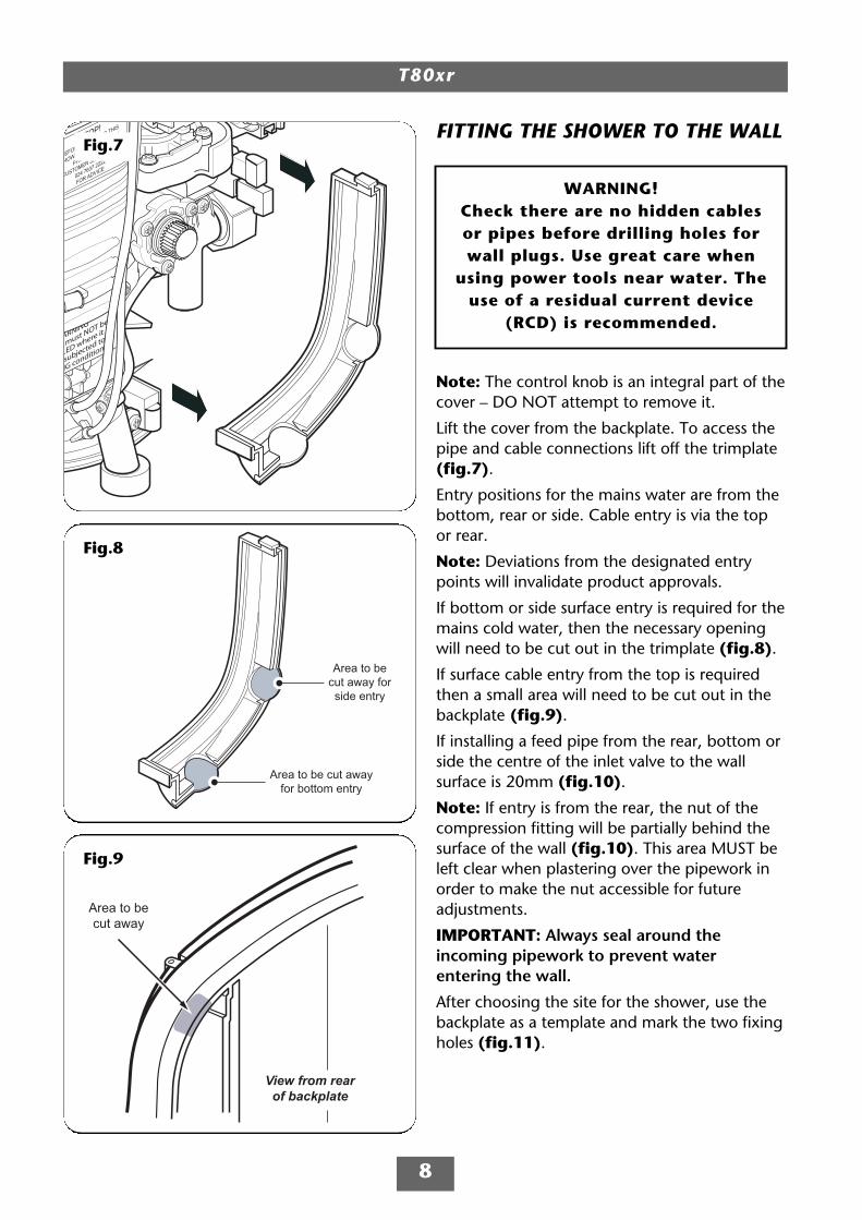
FITTING THE SHOWER TO THE WALL
Note: The control knob is an integral part of thecover – DO NOT attempt to remove it.
Lift the cover from the backplate. To access thepipe and cable connections lift off the trimplate(fig.7).
Entry positions for the mains water are from thebottom, rear or side. Cable entry is via the topor rear.
Note: Deviations from the designated entrypoints will invalidate product approvals.
If bottom or side surface entry is required for themains cold water, then the necessary openingwill need to be cut out in the trimplate (fig.8).
If surface cable entry from the top is requiredthen a small area will need to be cut out in thebackplate (fig.9).
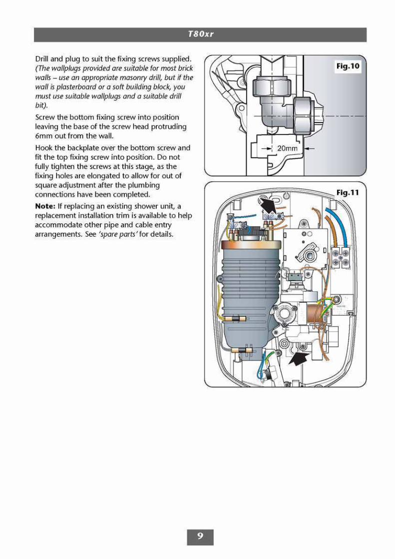
If installing a feed pipe from the rear, bottom orside the centre of the inlet valve to the wallsurface is 20mm (fig.10).
Note: If entry is from the rear, the nut of thecompression fitting will be partially behind thesurface of the wall (fig.10). This area MUST beleft clear when plastering over the pipework inorder to make the nut accessible for futureadjustments.
IMPORTANT: Always seal around theincoming pipework to prevent waterentering the wall.
After choosing the site for the shower, use thebackplate as a template and mark the two fixingholes (fig.11).
Fig.8
Fig.7
Area to becut away
View from rearof backplate
Fig.9
WARNING!Check there are no hidden cablesor pipes before drilling holes forwall plugs. Use great care when
using power tools near water. Theuse of a residual current device
(RCD) is recommended.
T80xr
10
PLUMBING CONNECTIONSPlumbing to be carried out before wiring
DO NOT use jointing compounds on any pipefittings for the installation.
DO NOT solder fittings near the shower unit asheat can transfer along the pipework anddamage components.
Compression fittings MUST be used to connectto the inlet of the shower. (Push-on fittings mustNOT be used as full engagement cannot beguaranteed).
Note: An additional stopvalve (complying withWater Regulations) MUST be fitted in the mainswater supply to the shower as an independentmeans of isolating the water supply shouldmaintenance or servicing be necessary.
IMPORTANT: Before completing theconnection of the water supply to the inlet ofthe shower, flush out the pipework toremove all swarf and system debris. This canbe achieved by connecting a hose to thepipework and turning on the mains watersupply long enough to clear the debris towaste.
ProcedureTurn off water supply either at the mainsstopvalve or the isolating stopvalve. Connect themains water supply to the inlet of the shower via15mm copper, stainless steel or plastic pipeusing a 15mm x 15mm elbow or straightcoupler compression fitting.
DO NOT use excessive force when making theseconnections.
Make sure the backplate is square on the walland tighten the two retaining screws which holdit to the wall.
Turn on the mains water supply and check forleaks in the pipework connection to the shower.
Note: At this stage no water can flow throughthe unit.
WARNING!
The outlet of the shower acts as avent and must NOT be connected toanything other than the hose and
sprayhead supplied.
T80xr
15
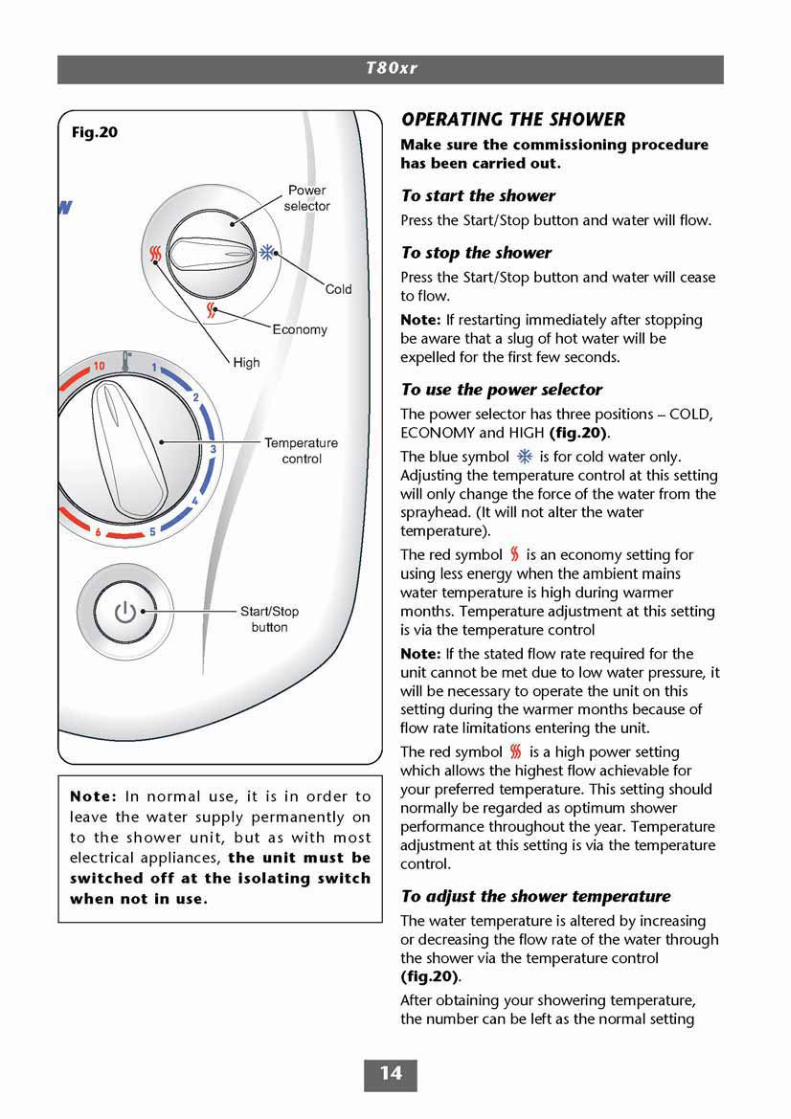
and should only need altering to compensatefor seasonal changes in ambient watertemperature.
Note: The preferred number on ECONOMY willgive a different temperature to the samenumber position on HIGH.
To decrease the shower temperatureTurn the temperature control anti-clockwise;this will increase the flow of water through theshower therefore decreasing the watertemperature, and is indicated by lowernumbers.
To increase the shower temperatureTurn the temperature control clockwise; this willdecrease the flow of water through the showertherefore increasing the water temperature, andis indicated by higher numbers.
Note: It is advisable to be certain that theshowering temperature is satisfactory by testingwith your hand before stepping under thesprayhead. There will always be a time delay ofa few seconds between selecting a flow rate andthe water reaching the stable temperature forthat flow rate.
CAUTION: It is recommended that personswho may have difficulty understanding oroperating the shower controls should not beleft unattended while showering. Specialconsideration should be given to youngchildren and the less able bodied.
WARNING!
After any servicing of mains watersupply, ALWAYS flush out the
pipework to remove any debris.Always make sure the unit is
started on COLD in order to purge
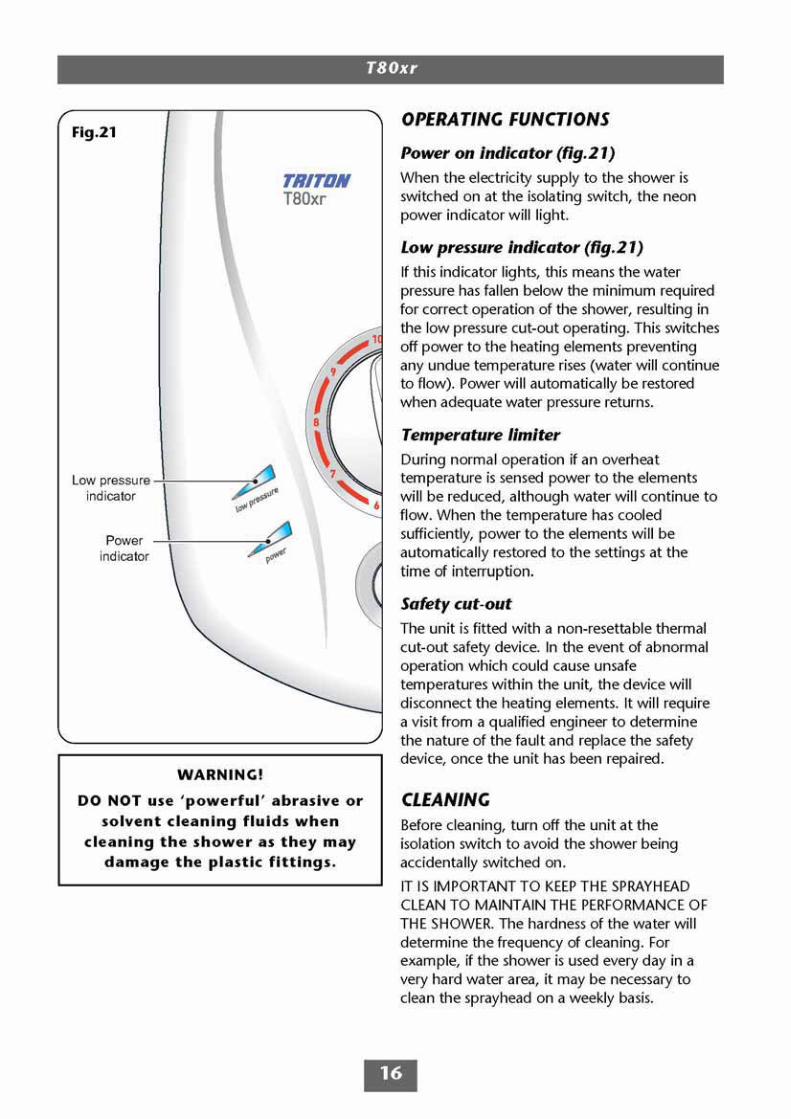
T80xr
17
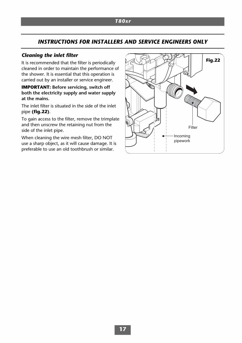
Cleaning the inlet filterIt is recommended that the filter is periodicallycleaned in order to maintain the performance ofthe shower. It is essential that this operation iscarried out by an installer or service engineer.
IMPORTANT: Before servicing, switch offboth the electricity supply and water supplyat the mains.
The inlet filter is situated in the side of the inletpipe (fig.22).
To gain access to the filter, remove the trimplateand then unscrew the retaining nut from theside of the inlet pipe.
When cleaning the wire mesh filter, DO NOTuse a sharp object, as it will cause damage. It ispreferable to use an old toothbrush or similar.
Filter
Incomingpipework
Fig.22
INSTRUCTIONS FOR INSTALLERS AND SERVICE ENGINEERS ONLY
T80xr
20
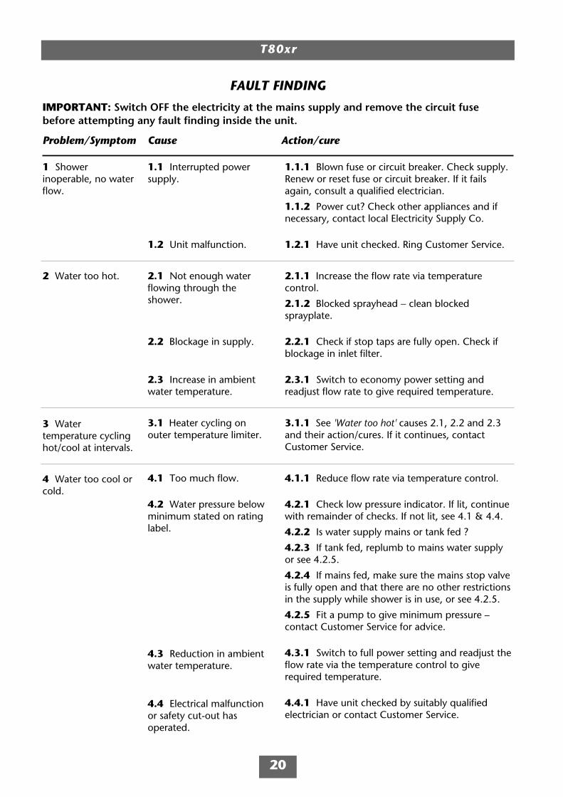
1 Showerinoperable, no waterflow.
2 Water too hot.
3 Watertemperature cyclinghot/cool at intervals.
4 Water too cool orcold.
1.1 Interrupted powersupply.
1.2 Unit malfunction.
2.1 Not enough waterflowing through theshower.
2.2 Blockage in supply.
2.3 Increase in ambientwater temperature.
3.1 Heater cycling onouter temperature limiter.
4.1 Too much flow.
4.2 Water pressure belowminimum stated on ratinglabel.
4.3 Reduction in ambientwater temperature.
4.4 Electrical malfunctionor safety cut-out hasoperated.
1.1.1 Blown fuse or circuit breaker. Check supply.Renew or reset fuse or circuit breaker. If it failsagain, consult a qualified electrician.
1.1.2 Power cut? Check other appliances and ifnecessary, contact local Electricity Supply Co.
1.2.1 Have unit checked. Ring Customer Service.
2.1.1 Increase the flow rate via temperaturecontrol.
2.1.2 Blocked sprayhead − clean blockedsprayplate.
2.2.1 Check if stop taps are fully open. Check ifblockage in inlet filter.
2.3.1 Switch to economy power setting andreadjust flow rate to give required temperature.
3.1.1 See 'Water too hot' causes 2.1, 2.2 and 2.3and their action/cures. If it continues, contactCustomer Service.
4.1.1 Reduce flow rate via temperature control.
4.2.1 Check low pressure indicator. If lit, continuewith remainder of checks. If not lit, see 4.1 & 4.4.
4.2.2 Is water supply mains or tank fed ?
4.2.3 If tank fed, replumb to mains water supplyor see 4.2.5.
4.2.4 If mains fed, make sure the mains stop valveis fully open and that there are no other restrictionsin the supply while shower is in use, or see 4.2.5.
4.2.5 Fit a pump to give minimum pressure –contact Customer Service for advice.
4.3.1 Switch to full power setting and readjust theflow rate via the temperature control to giverequired temperature.
4.4.1 Have unit checked by suitably qualifiedelectrician or contact Customer Service.
FAULT FINDING
IMPORTANT: Switch OFF the electricity at the mains supply and remove the circuit fusebefore attempting any fault finding inside the unit.
Problem/Symptom Cause Action/cure
T80xr
21
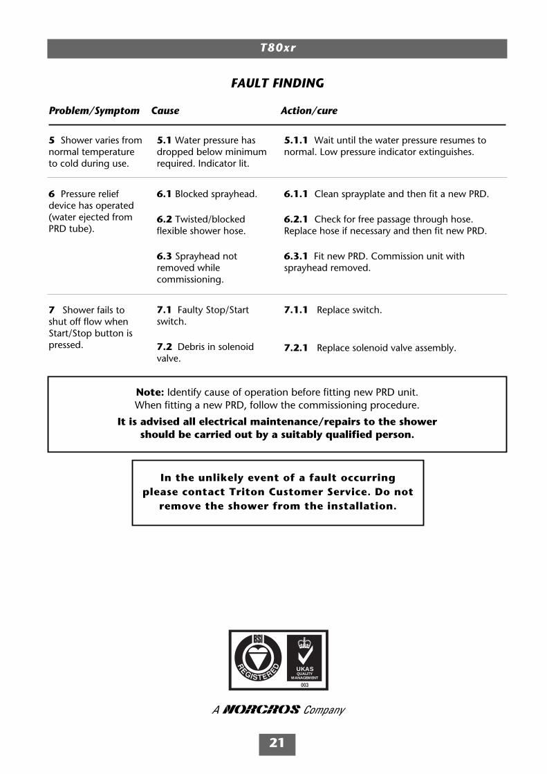
FAULT FINDING
Problem/Symptom Cause Action/cure
5 Shower varies fromnormal temperatureto cold during use.
6 Pressure reliefdevice has operated(water ejected fromPRD tube).
7 Shower fails toshut off flow whenStart/Stop button ispressed.
5.1 Water pressure hasdropped below minimumrequired. Indicator lit.
6.1 Blocked sprayhead.
6.2 Twisted/blockedflexible shower hose.
6.3 Sprayhead notremoved whilecommissioning.
7.1 Faulty Stop/Startswitch.
7.2 Debris in solenoidvalve.
5.1.1 Wait until the water pressure resumes tonormal. Low pressure indicator extinguishes.
6.1.1 Clean sprayplate and then fit a new PRD.
6.2.1 Check for free passage through hose.Replace hose if necessary and then fit new PRD.
6.3.1 Fit new PRD. Commission unit withsprayhead removed.
7.1.1 Replace switch.
7.2.1 Replace solenoid valve assembly.
Note: Identify cause of operation before fitting new PRD unit.When fitting a new PRD, follow the commissioning procedure.
It is advised all electrical maintenance/repairs to the showershould be carried out by a suitably qualified person.
UKASQUALITY
MANAGEMENT
003
In the unlikely event of a fault occurringplease contact Triton Customer Service. Do not
remove the shower from the installation.

Service PolicyIn the event of a complaint occurring, thefollowing procedure should be followed:1 Telephone Customer Service on +44 (0) 247637 2222 (+44 (0) 84 5762 6591 in Scotlandand in Northern Ireland), having available themodel number and power rating of the product,together with the date of purchase.2 Triton Customer Service will be able to confirmwhether the fault can be rectified by either theprovision of a replacement part or a site visit froma qualified Triton service engineer.3 If a service call is required it will be booked andthe date of call confirmed. In order to expediteyour request, please have your postcode availablewhen booking a service call.4 It is essential that you or an appointedrepresentative (who must be a person of 18 yearsof age or more) is present during the serviceengineer's visit and receipt of purchase is shown.5 A charge will be made in the event of anaborted service call by you but not by us, orwhere a call under the terms of guarantee hasbeen booked and the failure is not product related(i.e. scaling and furring, incorrect water pressure,pressure relief device operation, electricalinstallation faults). 6 If the product is no longer covered by theguarantee, a charge will be made for the site visitand for any parts supplied.7 Service charges are based on the account beingsettled when work is complete, the engineer willthen request payment for the invoice. If this is notmade to the service engineer or settled within tenworking days, an administration charge will beadded.
Replacement Parts PolicyAvailability: It is the policy of Triton to maintainavailability of parts for the current range ofproducts for supply after the guarantee hasexpired. Stocks of spare parts will be maintainedfor the duration of the product’s manufacture andfor a period of five years thereafter.In the event of a spare part not being available asubstitute part will be supplied.Payment: The following payment methods can beused to obtain spare parts:1 By post, pre-payment of pro forma invoice bycheque or money order.2 By telephone, quoting credit card (MasterCardor Visa) details.3 By website order, www.tritonshowers.co.uk
TRITON STANDARD GUARANTEETriton Plc guarantee this product against allmechanical and electrical defects arising fromfaulty workmanship or materials for a period oftwo years for domestic use only, from the date ofpurchase, provided that it has been installed by acompetent person in full accordance with thefitting instructions.Any part found to be defective during thisguarantee period we undertake to repair orreplace at our option without charge so long asit has been properly maintained and operated inaccordance with the operating instructions, andhas not been subject to misuse or damage.This product must not be taken apart, modifiedor repaired except by a person authorised byTriton Plc. This guarantee applies only toproducts installed within the United Kingdomand does not apply to products usedcommercially. This guarantee does not affectyour statutory rights.
What is not covered:1 Breakdown due to: a) use other thandomestic use by you or your resident family; b) wilful act or neglect; c) any malfunctionresulting from the incorrect use or quality ofelectricity, gas or water or incorrect setting ofcontrols; d) faulty installation.2 Repair costs for damage caused by foreignobjects or substances.3 Total loss of the product due to non-availability of parts.4 Compensation for loss of use of the productor consequential loss of any kind.5 Call out charges where no fault has beenfound with the appliance.6 The cost of repair or replacement of pressurerelief devices, sprayheads, hoses, riser railsand/or wall brackets, isolating switches, electricalcable, fuses and/or circuit breakers or any otheraccessories installed at the same time.7 The cost of routine maintenance,adjustments, overhaul modifications or loss ordamage arising therefrom, including the cost ofrepairing damage, breakdown, malfunctioncaused by corrosion, furring, pipe scaling,limescale, system debris or frost.
Triton PlcShepperton ParkCaldwell RoadNuneatonWarwickshire CV11 4NR
Customer Service: +44 (0) 24 7637 2222
Scottish and Northern IrelandCustomer Service: +44 (0) 84 5762 6591
Trade Installer Hotline: +44 (0) 24 7632 5491Fax: +44 (0) 24 7632 4564
www.tritonshowers.co.uk
E mail: [email protected]