t2x rtd temperature transmitter - signal conditioners or calibration of other instruments in the...
TRANSCRIPT

T2X RTD Temperature Transmitter
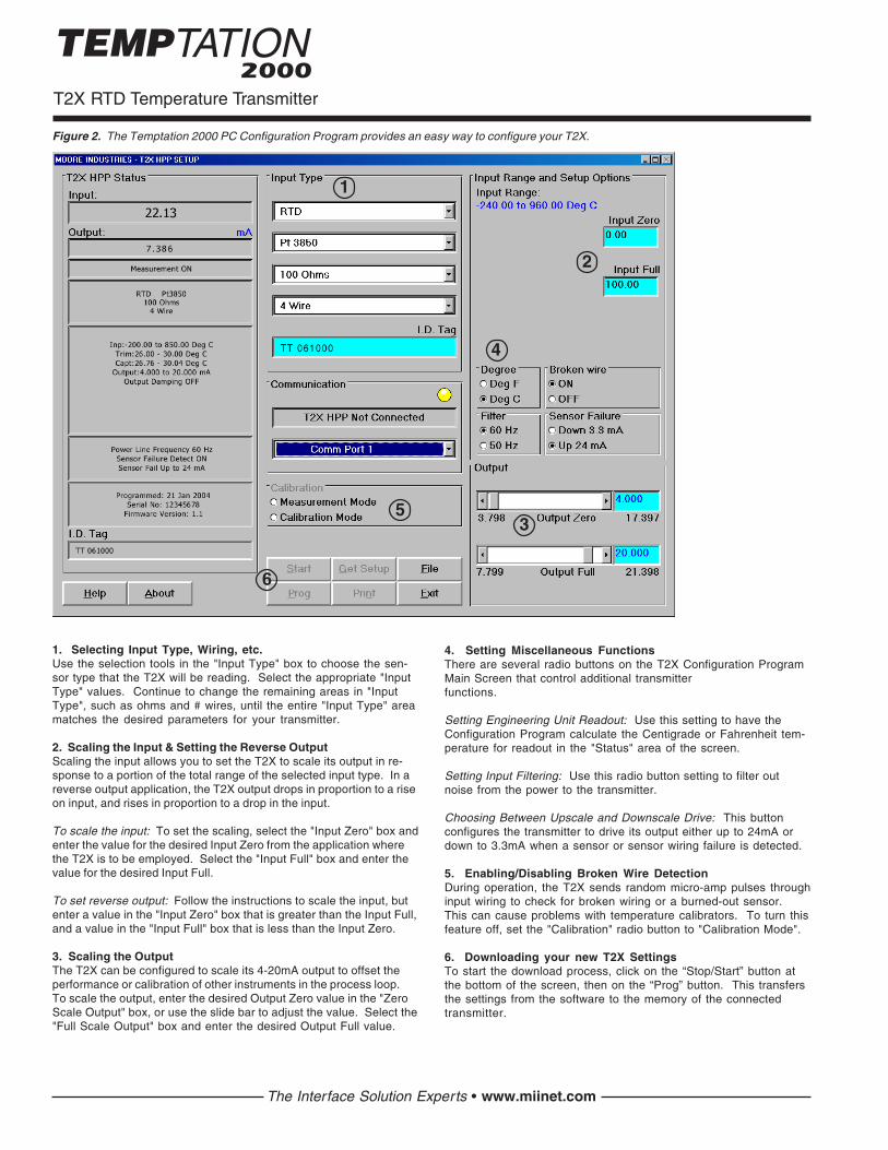
1. Selecting Input Type, Wiring, etc.Use the selection tools in the "Input Type" box to choose the sen-sor type that the T2X will be reading. Select the appropriate "InputType" values. Continue to change the remaining areas in "InputType", such as ohms and # wires, until the entire "Input Type" areamatches the desired parameters for your transmitter.
2. Scaling the Input & Setting the Reverse OutputScaling the input allows you to set the T2X to scale its output in re-sponse to a portion of the total range of the selected input type. In areverse output application, the T2X output drops in proportion to a riseon input, and rises in proportion to a drop in the input.
To scale the input: To set the scaling, select the "Input Zero" box andenter the value for the desired Input Zero from the application wherethe T2X is to be employed. Select the "Input Full" box and enter thevalue for the desired Input Full.
To set reverse output: Follow the instructions to scale the input, butenter a value in the "Input Zero" box that is greater than the Input Full,and a value in the "Input Full" box that is less than the Input Zero.
3. Scaling the OutputThe T2X can be configured to scale its 4-20mA output to offset theperformance or calibration of other instruments in the process loop.To scale the output, enter the desired Output Zero value in the "ZeroScale Output" box, or use the slide bar to adjust the value. Select the"Full Scale Output" box and enter the desired Output Full value.
Figure 2. The Temptation 2000 PC Configuration Program provides an easy way to configure your T2X.
4. Setting Miscellaneous FunctionsThere are several radio buttons on the T2X Configuration ProgramMain Screen that control additional transmitterfunctions.
Setting Engineering Unit Readout: Use this setting to have theConfiguration Program calculate the Centigrade or Fahrenheit tem-perature for readout in the "Status" area of the screen.
Setting Input Filtering: Use this radio button setting to filter outnoise from the power to the transmitter.
Choosing Between Upscale and Downscale Drive: This buttonconfigures the transmitter to drive its output either up to 24mA ordown to 3.3mA when a sensor or sensor wiring failure is detected.
5. Enabling/Disabling Broken Wire DetectionDuring operation, the T2X sends random micro-amp pulses throughinput wiring to check for broken wiring or a burned-out sensor.This can cause problems with temperature calibrators. To turn thisfeature off, set the "Calibration" radio button to "Calibration Mode".
6. Downloading your new T2X SettingsTo start the download process, click on the “Stop/Start” button atthe bottom of the screen, then on the “Prog” button. This transfersthe settings from the software to the memory of the connectedtransmitter.
The Interface Solution Experts • www.miinet.com
1
2
3
4
5
6

T2X RTD Temperature Transmitter
The Interface Solution Experts • www.miinet.com
SpecificationsInput Accuracy:Platinum RTD,±0.2°C (±0.36°F)Nickel RTD,±0.16°C (±0.29°F)Copper RTD,±1.2°C (±2.16°F)Ohms, ±0.4ΩOutput Accuracy:±0.05% of output spanNOTE: Overall accuracy isdetermined by combininginput and output accuracy.It includes the combinedeffects of linearity,hysteresis, repeatability,and adjustment resolution.It does not include ambienttemperature effect.Stability (max. span):1 year = ±0.12%3 years = ±0.21%5 years = ±0.27%Measurement Cycle:Output updates at least 5times per secondOutput Response Time:256msec typical, 360msecmaximum, for the output tochange from 10% to 90% foran input step change of 0%to 100%
Ripple: 10mV peak-to-peak measured across a250 ohm load resistor atfrequencies up to 120HzOver-Voltage Protection:Input, 4Vdc peak, max.;Output, 48Vdc, max.Digital Input Filter:User-selectable, 50/60HzPower Supply and LoadEffects: Negligible withinspecified power limitsLoad Capability:670 ohms @ 24V
Ω Ω Ω Ω Ω = (Supply Voltage - 8V)
0.024ABurnout Protection:User-programmable,Upscale to 24mA;Downscale to 3.3mAOutput Current Limiting:25mA maximumRTD Lead WireResistance Maximum:RTD resistance + 2 timesthe lead wire resistancemust be less than 2000ohms; Recommended <35ohms per wire for three wireinputs; <5 ohms per wire for10 ohm Cu inputsRTD & Ohms Excitation:250µA, ±10%
AmbientConditions
Set Up
Weight
Operating & Storage Range:-40°C to +85°C(-40°F to +185°F)Relative Humidity:0-95%, non-condensingAmbient Temperature Effect:±0.03% of output span/°CRFI/EMI Immunity:CE compliant when testedaccording to IEC 61326Noise Rejection:Common mode: 100dB @50/60Hz; Normal Mode: 70dBtypical at 200mV peak-to-peak @50/60Hz
All settings are made usingMoore Industries’ Intelligent PCConfiguration Software, and thenstored in nonvolatile memory
HPP: 101 g (3.6 oz)HPP in LH1: 428 g (15.1 oz)HPP in LH2: 654 g (1 lb. 7 oz)HPP in CH6: 173 g (6.1 oz)
Configuration Software andCableEach T2X order comes with onecopy of our Configuration Software(Windows 95, 98, NT, 2000 and XPcompatible). To order additionalcopies:
Software:PART NUMBER: 750-75E05-01
PC-to-Transmitter ConfigurationCable:PART NUMBER: 803-040-26
Maximum Range*
-240 to 960°C-400 to 1760°F
-240 to 300°C-400 to 572°F
-150 to 720°C-238 to 1328°F
-150 to 300°C-238 to 572°F
-240 to 580°C-400 to 1076°F
-100 to 360°C-148 to 680°F
-203.19 to 300.53°C-333.74 to 572.95°F
0-2200Ω
MinimumSpan
10°C18°F
10°C18°F
100°C180°F
30ΩΩΩΩΩΩ
Type
Platinum
Nickel
Copper
ResistancePotentiometer
100, 200,300, 400, 500
1000
100, 200,400, 500
1000
100
120
9.035
0-2200Ω
Input
RTD2-Wire3-Wire4-Wire
0.003850
0.003902
0.003916
0.00672
0.00427
N/A
*Transmitter will measure ranges outside of the Conformance Range with some degradation to accuracy ratings. Consult the factory for details.
Input Types and Ranges
ΩΩΩΩΩ
Performance(continued)
Performance
ConformanceRange
-200 to 850°C-328 to 1562°F
-200 to 300°C-328 to 572°F
-100 to 650°C-148 to 1202°F
-100 to 300°C-148 to 572°F
-200 to 510°C-328 to 950°F
-80 to 320°C-112 to 608°F
-50 to 250°C-58 to 482°F
0-2200Ω
ααααα
T2X RTD Temperature Transmitter
United States • [email protected]: (818) 894-7111 • FAX: (818) 891-2816
Australia • [email protected]: (02) 8536-7200 • FAX: (02) 9525-7296
Belgium • [email protected]: 03/448.10.18 • FAX: 03/440.17.97
The Netherlands • [email protected]: (0)344-617971 • FAX: (0)344-615920
China • [email protected]: 86-21-62491499 • FAX: 86-21-62490635
United Kingdom • [email protected]: 01293 514488 • FAX: 01293 536852
Rosemount is a registered trademark of Rosemount Inc.235-781-00 C
+PS
23
4
1
–PS
33mm
TOP VIEW BOTTOM VIEW
SIDE VIEW
CLCL
(1.3 in)
52mm(2.04 in)
49mm(1.92 in)
26mm(1.04 in)
33mm(1.3 in)
Mounting Holes DIA. 7mm (0.28 in)
Center Hole DIA. 6mm (0.24 in)
2-WIRE RTDor DECADE
RESISTANCEBOX
+PS
23
4
1
–PS
–
–
+
+ – +
POWERSOURCE8-42Vdc
CURRENT-DRIVEN
INSTRUMENT
3-WIRE RTDOR DECADE
RESISTANCE BOX
4-WIRE RTDOR DECADE
RESISTANCE BOX
POTENTIOMETERINPUT
23
4
1
23
4
1
23
4
1
23
4
1
2-WIRE RTDOR DECADE
RESISTANCE BOX
Dimensions
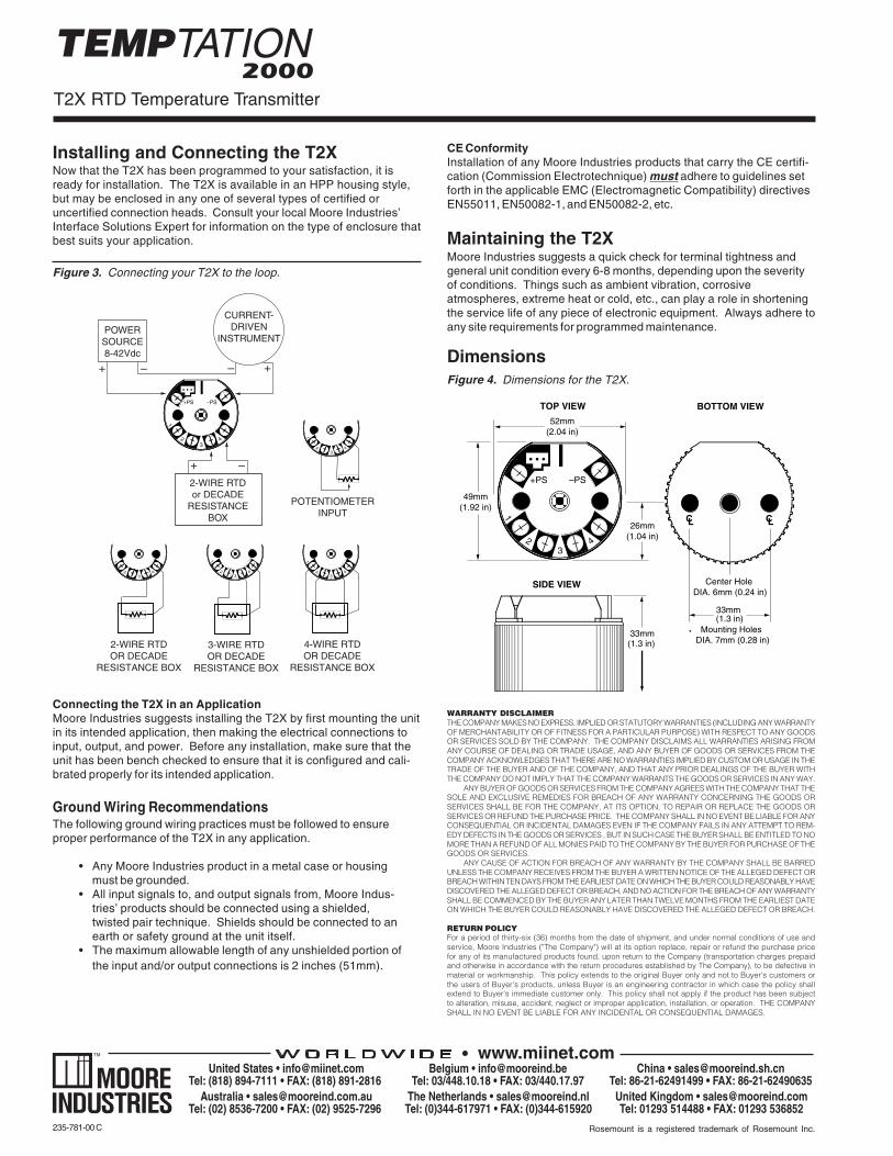
Figure 3. Connecting your T2X to the loop.
Figure 4. Dimensions for the T2X.
Installing and Connecting the T2XNow that the T2X has been programmed to your satisfaction, it isready for installation. The T2X is available in an HPP housing style,but may be enclosed in any one of several types of certified oruncertified connection heads. Consult your local Moore Industries’Interface Solutions Expert for information on the type of enclosure thatbest suits your application.
CE ConformityInstallation of any Moore Industries products that carry the CE certifi-cation (Commission Electrotechnique) must adhere to guidelines setforth in the applicable EMC (Electromagnetic Compatibility) directivesEN55011, EN50082-1, and EN50082-2, etc.
Maintaining the T2XMoore Industries suggests a quick check for terminal tightness andgeneral unit condition every 6-8 months, depending upon the severityof conditions. Things such as ambient vibration, corrosiveatmospheres, extreme heat or cold, etc., can play a role in shorteningthe service life of any piece of electronic equipment. Always adhere toany site requirements for programmed maintenance.
WARRANTY DISCLAIMERTHE COMPANY MAKES NO EXPRESS, IMPLIED OR STATUTORY WARRANTIES (INCLUDING ANY WARRANTYOF MERCHANTABILITY OR OF FITNESS FOR A PARTICULAR PURPOSE) WITH RESPECT TO ANY GOODSOR SERVICES SOLD BY THE COMPANY. THE COMPANY DISCLAIMS ALL WARRANTIES ARISING FROMANY COURSE OF DEALING OR TRADE USAGE, AND ANY BUYER OF GOODS OR SERVICES FROM THECOMPANY ACKNOWLEDGES THAT THERE ARE NO WARRANTIES IMPLIED BY CUSTOM OR USAGE IN THETRADE OF THE BUYER AND OF THE COMPANY, AND THAT ANY PRIOR DEALINGS OF THE BUYER WITHTHE COMPANY DO NOT IMPLY THAT THE COMPANY WARRANTS THE GOODS OR SERVICES IN ANY WAY.
ANY BUYER OF GOODS OR SERVICES FROM THE COMPANY AGREES WITH THE COMPANY THAT THESOLE AND EXCLUSIVE REMEDIES FOR BREACH OF ANY WARRANTY CONCERNING THE GOODS ORSERVICES SHALL BE FOR THE COMPANY, AT ITS OPTION, TO REPAIR OR REPLACE THE GOODS ORSERVICES OR REFUND THE PURCHASE PRICE. THE COMPANY SHALL IN NO EVENT BE LIABLE FOR ANYCONSEQUENTIAL OR INCIDENTAL DAMAGES EVEN IF THE COMPANY FAILS IN ANY ATTEMPT TO REM-EDY DEFECTS IN THE GOODS OR SERVICES , BUT IN SUCH CASE THE BUYER SHALL BE ENTITLED TO NOMORE THAN A REFUND OF ALL MONIES PAID TO THE COMPANY BY THE BUYER FOR PURCHASE OF THEGOODS OR SERVICES.
ANY CAUSE OF ACTION FOR BREACH OF ANY WARRANTY BY THE COMPANY SHALL BE BARREDUNLESS THE COMPANY RECEIVES FROM THE BUYER A WRITTEN NOTICE OF THE ALLEGED DEFECT ORBREACH WITHIN TEN DAYS FROM THE EARLIEST DATE ON WHICH THE BUYER COULD REASONABLY HAVEDISCOVERED THE ALLEGED DEFECT OR BREACH, AND NO ACTION FOR THE BREACH OF ANY WARRANTYSHALL BE COMMENCED BY THE BUYER ANY LATER THAN TWELVE MONTHS FROM THE EARLIEST DATEON WHICH THE BUYER COULD REASONABLY HAVE DISCOVERED THE ALLEGED DEFECT OR BREACH.
RETURN POLICYFor a period of thirty-six (36) months from the date of shipment, and under normal conditions of use andservice, Moore Industries ("The Company") will at its option replace, repair or refund the purchase pricefor any of its manufactured products found, upon return to the Company (transportation charges prepaidand otherwise in accordance with the return procedures established by The Company), to be defective inmaterial or workmanship. This policy extends to the original Buyer only and not to Buyer's customers orthe users of Buyer's products, unless Buyer is an engineering contractor in which case the policy shallextend to Buyer's immediate customer only. This policy shall not apply if the product has been subjectto alteration, misuse, accident, neglect or improper application, installation, or operation. THE COMPANYSHALL IN NO EVENT BE LIABLE FOR ANY INCIDENTAL OR CONSEQUENTIAL DAMAGES.
Connecting the T2X in an ApplicationMoore Industries suggests installing the T2X by first mounting the unitin its intended application, then making the electrical connections toinput, output, and power. Before any installation, make sure that theunit has been bench checked to ensure that it is configured and cali-brated properly for its intended application.
Ground Wiring RecommendationsThe following ground wiring practices must be followed to ensureproper performance of the T2X in any application.
• Any Moore Industries product in a metal case or housingmust be grounded.
• All input signals to, and output signals from, Moore Indus-tries’ products should be connected using a shielded,twisted pair technique. Shields should be connected to anearth or safety ground at the unit itself.
• The maximum allowable length of any unshielded portion ofthe input and/or output connections is 2 inches (51mm).

User’s Manual SupplementPhysical Instructions for Installing an
Encapsulated Hockey-Puck (HPP) Instrumentand LH2 Field-Mount Enclosure Apparatus
The Interface Solution Experts • www.miinet.com700-764-00A
January 2001
The Physical Instructions Supplement providesreferences and additional information for safely installingand commissioning a Moore Industries’ Hockey-Puckinstrument and LH2 Field-Mount Enclosure Apparatus.
Instrument Labeling and Identification—The fullyassembled apparatus consists of a Moore Industries’Hockey-Puck unit securely mounted in an LH2enclosure. Such an apparatus is intended for use inboth indoor and outdoor Hazardous (Classified)Locations where a degree of protection from windblowndust and rain, splashing and hose-directed water, andprotection from the formation of ice on the enclosure isrequired. A series of selected Moore Industries’ 2-Wirehockey-puck style units mounted in the LH2 enclosure(consult factory for a list of the certified instruments) arecertified as an Explosion-Proof and Dust Ignition-Proofappartus in accordance with Factory Mutual Research‘3600’ standard (NEC-based) and as Flame-Proof inaccordance with the CENELEC/ATEX Directive 94/9/EC(IEC-based). For applications intended in North Americaand other related areas, the approval classifications arestated on the externally mounted metal ID Tag to be FMapproved as Explosion-Proof for Class I, Division 1,Groups A, B, C and D; Dust Ignition-Proof for Class II/III,Division 1, Groups E, F and G; T6 @ 60°C MaximumOperating Ambient Temperature. In regards toprotection from Environmental hazards/effects, theapparatus carries a NEMA Type 4X rating with anIngress Protection Code of IP66 as per IEC-529. Forapplications intended in Europe and other related areas,the ID Tag clearly states that the apparatus is certified byISSeP to be Flame-Proof and marked as such:
II 2GD EEx d IIC; T6 @ Tamb. (-20°C ≤ Tamb.≤ +60°C). The temperature marking for dust atmo-spheres is up to + 80°C. The maximum power param-eters are: Vmax = 42 VDC, Imax = 110 mA andPmax = 2W. Also, the tag clearly shows the CE markingdenoting full compliance with the relevant EuropeanCommunity directives applicable to the ProcessInstrumentation Industry. For 2-wire transmitters certifiedand intended to be operated as either Intrinsically Safe,Non-Incendive (Class I, Div. 2) or Type N; the powerparameters are clearly stated on both the Instrument IDLabel and the Apparatus ID Tag. Also, the powerparameters and cabling requirements are stated in the‘Intrinsically Safe Barrier and Field Installation Diagram’that is included in the relevant User’s Manuals. Thisapparatus is designed in such a way that it: a) does notgive rise to physical injury or other harm due to contact,b) does not produce excessive surface temperature,infra-red, electromagnetic, ionizing radiation and, c)have no non-electrical dangers.
CAUTIONRead, understand and adhere to the manufacturer’sinstallation and operating procedures. Substitution ofcomponents may impair the instrument’s Intrinsic Safetyand/or Non-Incendivity. Keep cover tightly closed. Do notopen unit when energized. Do not open unit when eitheran explosive gas or dust atmosphere is present. Cableentry temperature may exceed 70°C. Cabling to besuitable. Do not allow layers of dust to accumulate onthe surfaces of the equipment. Disconnect power beforeservicing.
Contact Information—If you have installation, mainte-nance, periodic service, warranty questions or emer-gency repair requirements, please contact the nearestMoore Industries sales and service office. Contactinformation can be found on the back of this Supplement,in the User’s Manual for the instrument, or at MooreIndustries’ web site: www.miinet.com
User’s Manual—Complete information for an individualinstrument model can be found in the Moore IndustriesUser’s Manual for that instrument. The manual providesinformation for putting the instrument safely into service.This, where applicable, includes instructions, drawingsand diagrams. The Manual also includes appropriateWarnings, Cautionary Statements, and Notes.
User’s Manual components, where applicable, include:Introduction—Brief description of the instrument and itsgeneral application and use.Specifications—Provides electrical and environmentalconditions under which the instrument is designed tosafely perform.Ordering Information—Provides a description of theproduct model number to assist in verifying that theinstrument received matches the instrument ordered forthe installation.Calibration and Configuration—Describes how toaccomplish instrument settings and adjustment requiredto set up the unitInstallation and Connection—Describes how to installthe instrument and make electrical connections(including terminal designations). See the back of thisSupplement for additional information on how to installthe hockey-puck instrument into the LH2 enclosure.Maintenance—Describes recommended maintenance (ifany required) for the instrument. The user should consulttheir own maintenance procedures for any site-specificmaintenance procedures (such as scheduled re-calibrations) or other maintenance schedules that mayapply to instruments such as those supplied by MooreIndustries.Troubleshooting—Describes, where applicable,procedures for correcting any operational difficulties thatmay be encountered as a result of improper configura-tion/calibration or installation of the instrument.Customer Support—Describes the procedure andinformation required to efficiently receive answers toquestions regarding instrument installation, set up, oroperation.
User’s Manual SupplementPhysical Instructions for Installing anEncapsulated Hockey-Puck (HPP) Instrumentand LH2 Field-Mount Enclosure Apparatus
Specifications and information subject to change without notice.© 2006 Moore Industries-International, Inc.
United States • [email protected]: (818) 894-7111 • FAX: (818) 891-2816
Australia • [email protected]: (02) 8536-7200 • FAX: (02) 9525-7296
Belgium • [email protected]: 03/448.10.18 • FAX: 03/440.17.97
The Netherlands • [email protected]: (0)344-617971 • FAX: (0)344-615920
China • [email protected]: 86-21-62491499 • FAX: 86-21-62490635
United Kingdom • [email protected]: 01293 514488 • FAX: 01293 536852
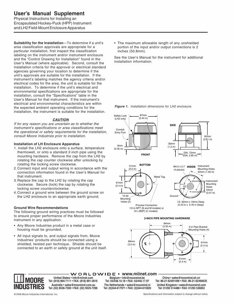
Figure 1. Installation dimensions for LH2 enclosure.
Suitability for the Installation—To determine if a unit’sarea classification approvals are appropriate for aparticular installation, first inspect the classificationlabeling on the instrument and/or instrument enclosureand the “Control Drawing for Installation” found in theUser’s Manual (where applicable). Second, consult theinstallation criteria for the approval or electrical standardagencies governing your location to determine if theunit’s approvals are suitable for the installation. If theinstrument’s labeling matches the agency criteria and/orelectrical codes for the area, the unit is suitable for theinstallation. To determine if the unit’s electrical andenvironmental specifications are appropriate for theinstallation, consult the “Specifications” table in theUser’s Manual for that instrument. If the instrument’selectrical and environmental characteristics are withinthe expected ambient operating conditions for theinstallation, the instrument is suitable for the installation.
CAUTIONIf for any reason you are uncertain as to whether theinstrument’s specifications or area classifications meetthe operational or safety requirements for the installation,consult Moore Industries prior to installation.
Installation of LH Enclosure Apparatus1. Install the LH2 enclosure onto a surface, temperature
thermowell, or onto a standard 2-inch pipe using themounting hardware. Remove the cap from the LH2 byrotating the cap counter clockwise after unlocking byrotating the locking screw clockwise.
2. Connect input and output wiring in accordance with theconnection information found in the User’s Manual forthat instrument.
3. Replace the cap to the LH2 by rotating the capclockwise. Secure (lock) the cap by rotating thelocking screw counterclockwise.
4. Connect a ground wire between the ground screw onthe LH2 enclosure to an appropriate earth ground.
Ground Wire RecommendationsThe following ground wiring practices must be followedto ensure proper performance of the Moore Industriesinstrument in any application.
• Any Moore Industries product in a metal case orhousing must be grounded.
• All input signals to, and output signals from, MooreIndustries’ products should be connected using ashielded, twisted pair technique. Shields should beconnected to an earth or safety ground at the unit itself.
• The maximum allowable length of any unshieldedportion of the input and/or output connections is 2inches (50.8mm).
See the User’s Manual for the instrument for additionalinstallation information.
92mm(3.61 in)
9mm(0.35 in)
87mm(3.44 in)
ConduitEntry Port
89mm(3.5 in)
84mm(3.30 in)
CL
61mm(2.4 in)
2-in Pipe Bracket Mounting Holes (4)
61mm(2.4 in)
Process Connection1/2-in NPT (N and M models) or
G½ (BSP) (C models)
61mm(2.4 in)
10-32Mounting Holes (2)
51mm(2.0 in)
Safety Lock(LH2 only)
Metal Tag
BOTTOMINSIDE
2-INCH PIPE MOUNTING HARDWARE
30mm(1.2 in)
DIA. 72mm(DIA. 2.85 in)
InstrumentMounting Holes40mm (1.56 in)
InstrumentMountingHoles33mm(3.07 in)
I.D. 62mm x 19mm Deep(2.43 in x 0.76 in Deep)
Ground
M4.0 x 0.7 (4 places)
FRONT
SIDE