t revolutionary aerospace systems concepts – academic...
TRANSCRIPT

RASC-AL May 18-21, 2003 - Page 1
SC
OU
T
University of MarylandSpace Systems Design
Revolutionary Aerospace Systems Concepts– Academic Linkage
ConferenceMay 18-21, 2003

RASC-AL May 18-21, 2003 - Page 2
SC
OU
T
University of MarylandSpace Systems Design
Potential Problem• Space station manned with a 3 member crew• Critical failure requires an EVA• Today’s solution to fix problem:
– Astronaut Emergency EVA• Requires 3 crew members
– First maneuvers Remote Manipulator System (RMS) to location» Low speed/ lengthy process - Loaded: 0.06m/sec (2.4in/sec)» Immediate operation initiation required
– Second and Third must head to airlock for pre-breathing» Time required: 4 hours» One crew member maneuvered at problem site by RMS» One crew member is a free floater
• Leaves no one to operate the station
Example Scenario: Intelsat rescue mission (3 crew out for EVA)
RASC-AL May 18-21, 2003 - Page 3
SC
OU
T
University of MarylandSpace Systems Design
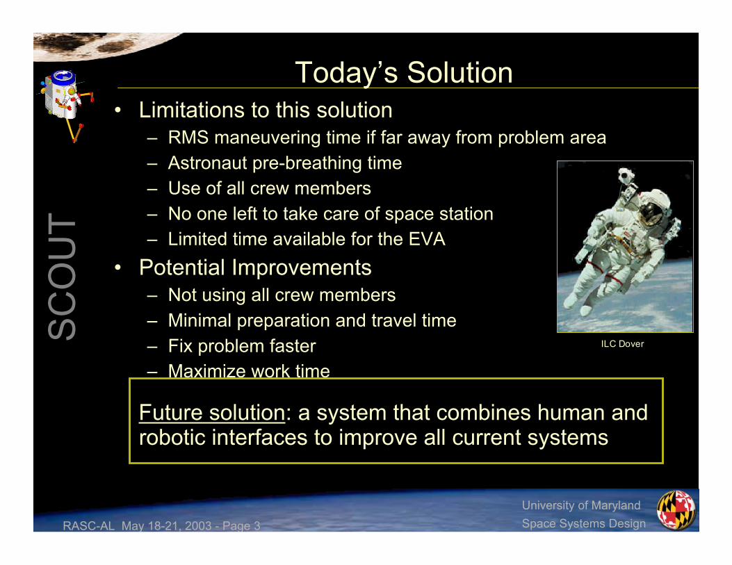
Today’s Solution• Limitations to this solution
– RMS maneuvering time if far away from problem area– Astronaut pre-breathing time– Use of all crew members– No one left to take care of space station– Limited time available for the EVA
• Potential Improvements– Not using all crew members– Minimal preparation and travel time– Fix problem faster– Maximize work time
Future solution: a system that combines human androbotic interfaces to improve all current systems
ILC Dover

RASC-AL May 18-21, 2003 - Page 4
SC
OU
T
University of MarylandSpace Systems Design
Space Construction & Orbital Utility Transport• Proposed element of the Orbital
Aggregation & SpaceInfrastructure Systems (OASIS)program
• Designed to operate withproposed Gateway Station at theEarth-Moon L1 Point
• Closed-cabin atmosphericsystem for EVA
• SCOUT System:– Two SCOUT pods– Docking Module (DM)– eXtended Mission Pallet (XMP)

RASC-AL May 18-21, 2003 - Page 5
SC
OU
T
University of MarylandSpace Systems Design
Overview• Design Requirements/ Constraints• SCOUT Systems Summary• Mission Planning• Support Infrastructure• Task Requirements• Interior/ Exterior Features• Life Support and Human Factors• Structures/ Thermal• Propulsion/ RCS• Power/ Avionics• Costing• EVA Systems Comparison• Conclusions

RASC-AL May 18-21, 2003 - Page 6
SC
OU
T
University of MarylandSpace Systems Design
Level One Design Requirements• Vehicle requirements
– Operate from the L1 Gateway system– Interact with worksite using hands and dexterous manipulators– Attach to and control the worksite (reference worksite: HST)– Provide low-contamination propulsion system for use in contamination-critical
regions– Provide for on-board human control, on-board autonomous control,
supervisory control, and teleoperation– Single-interface replenishment at the docking port capable of single-person
checkout and refurbishment between each use (time < 1 hour)– All safety-critical systems shall be two-fault tolerant– Support extended missions
• Capability requirements– Provide capability to operate at International Space Station with minimal
modifications– Standard operational capabilities shall meet or exceed EVA capabilities
demonstrated on HST and ISS• System requirements
– Design in accordance with NASA Standard JSC-28354, Human-RatingRequirements
– Minimum TRL of 3 by Jan. 1, 2005 and minimum TRL of 6 by Jan.1, 2008– Launch on US launch vehicles currently planned to be operational in 2005

RASC-AL May 18-21, 2003 - Page 7
SC
OU
T
University of MarylandSpace Systems Design
SCOUT Major Design Constraints• Task/human arm interaction• Worksite attach/control• Zero pre-breathe• Shirt-sleeve operation• Operating Pressure: 8.3 psi• RMS attach fitting• International Berthing and
Docking Mechanism (IBDM)with internal hatch opening
• Escape system placement
RASC-AL May 18-21, 2003 - Page 8
SC
OU
T
University of MarylandSpace Systems Design
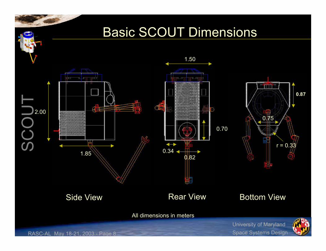
Basic SCOUT Dimensions
0.340.82
1.85
1.50
0.75
r = 0.33
0.70
2.00
0.87
Rear ViewSide View Bottom View
All dimensions in meters

RASC-AL May 18-21, 2003 - Page 9
SC
OU
T
University of MarylandSpace Systems Design
Vehicle Mass/Power Breakdown
Total
Power, Propulsion,and Thermal
Avionics
Life Support andHuman Factors
Loads, Structures,and Mechanisms
System
91518502000
85633675
295190200
295235275
240796850
Power (W)Actual Mass (kg)Allotted Mass (kg)
RASC-AL May 18-21, 2003 - Page 10
SC
OU
T
University of MarylandSpace Systems Design
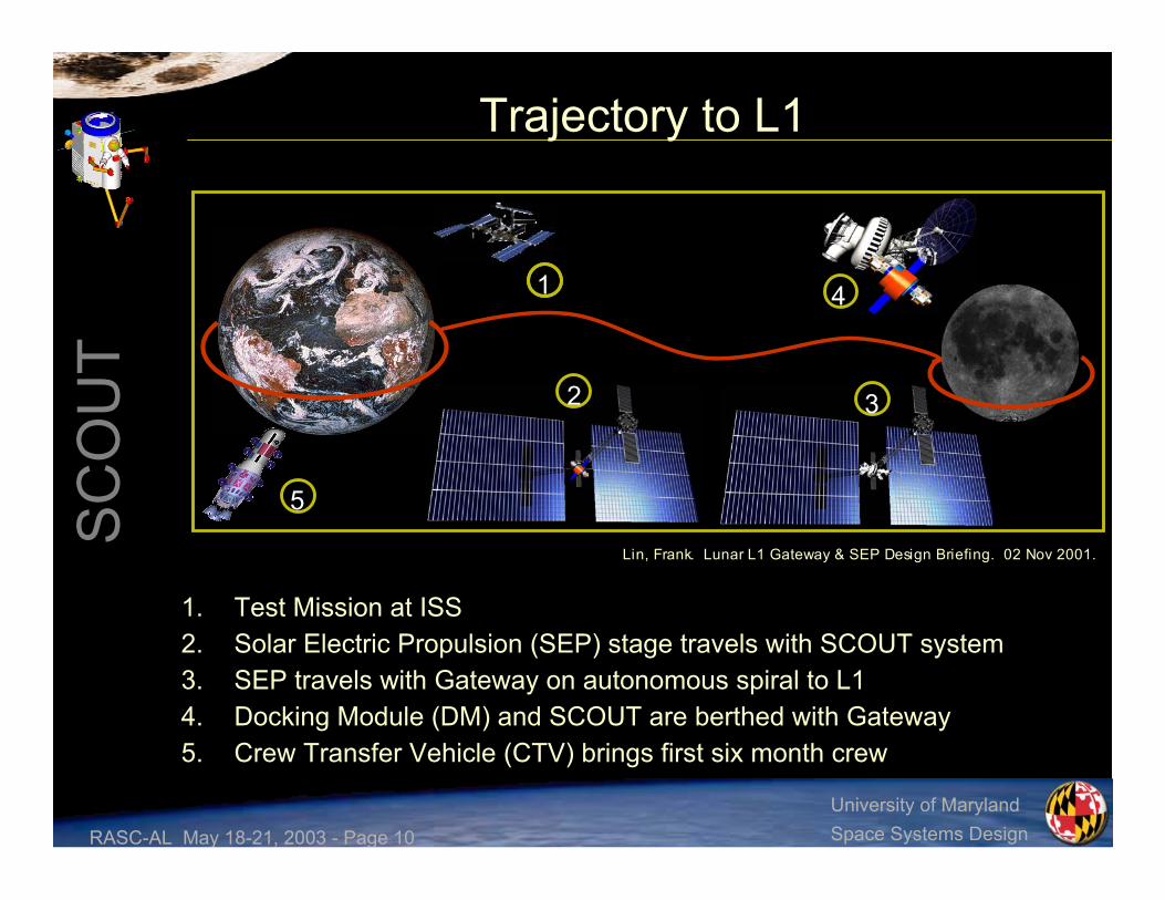
Trajectory to L1
1. Test Mission at ISS2. Solar Electric Propulsion (SEP) stage travels with SCOUT system3. SEP travels with Gateway on autonomous spiral to L14. Docking Module (DM) and SCOUT are berthed with Gateway5. Crew Transfer Vehicle (CTV) brings first six month crew
Lin, Frank. Lunar L1 Gateway & SEP Design Briefing. 02 Nov 2001.
1
5
32
4
RASC-AL May 18-21, 2003 - Page 11
SC
OU
T
University of MarylandSpace Systems Design
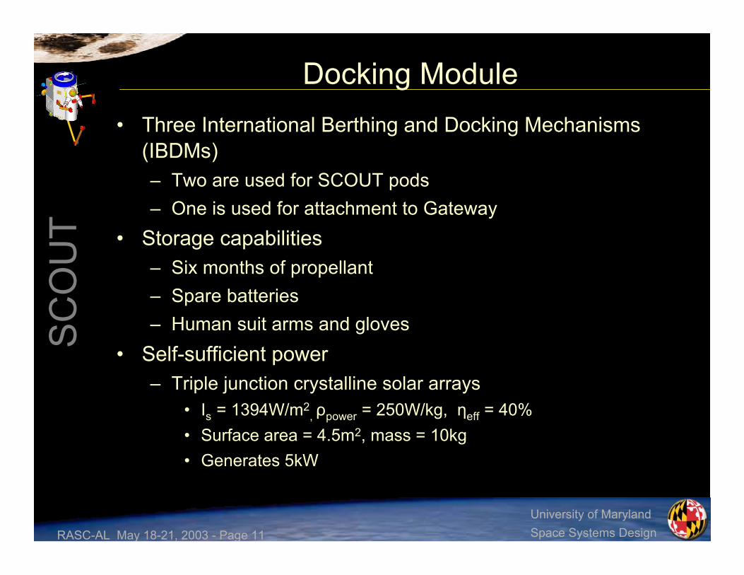
Docking Module• Three International Berthing and Docking Mechanisms
(IBDMs)– Two are used for SCOUT pods– One is used for attachment to Gateway
• Storage capabilities– Six months of propellant– Spare batteries– Human suit arms and gloves
• Self-sufficient power– Triple junction crystalline solar arrays
• Is = 1394W/m2, ρpower = 250W/kg, ηeff = 40%
• Surface area = 4.5m2, mass = 10kg• Generates 5kW

RASC-AL May 18-21, 2003 - Page 12
SC
OU
T
University of MarylandSpace Systems Design
Resupply Plan• SCOUT vehicles are designed to automatically resupply fuel,
atmospheric consumables, and power after each sortie duringDM attachment
• Docking Module resupply– Every six months for a nominal mission model– Every three months for an aggressive mission model
• OASIS infrastructure vehicles– Crew Transfer Vehicle (CTV) rotates crew and carries human
consumables every six months, and life support every two years– Hybrid Propellant Module (HPM) resupplies LOX and LH2 every
six months– Chemical Transfer Module (CTM) ferries payloads short
distances, provides a high impulse transfer from LEO to L1, and isused for extended missions
RASC-AL May 18-21, 2003 - Page 13
SC
OU
T
University of MarylandSpace Systems Design
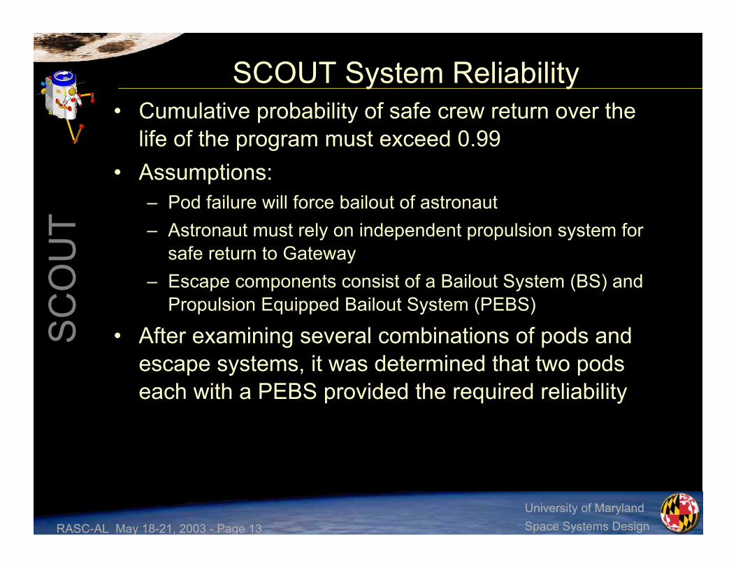
SCOUT System Reliability• Cumulative probability of safe crew return over the
life of the program must exceed 0.99• Assumptions:
– Pod failure will force bailout of astronaut– Astronaut must rely on independent propulsion system for
safe return to Gateway– Escape components consist of a Bailout System (BS) and
Propulsion Equipped Bailout System (PEBS)
• After examining several combinations of pods andescape systems, it was determined that two podseach with a PEBS provided the required reliability

RASC-AL May 18-21, 2003 - Page 14
SC
OU
T
University of MarylandSpace Systems Design
Nominal and Aggressive Missions• Nominal six-month mission consists of 30 sorties between both pods
– Eleven hours spent in the pod for eight hours of work– Total SCOUT hours for two pods: 240 working hours and 330 hours inside
the pod– Pod end of life occurs at 20 years
• Aggressive mission model doubles sortie and resupply rates
Break 2 – Lunch05:15:00
Work Period 203:15:00
Break 103:00:00
Work Period 101:00:00
Attach to worksite00:30:00
Travel to worksite00:00:00
ActivityStart TimeExample Sortie
Total Sortie Time11:00:00
Dock to Gateway10:30:00
Travel to Gateway10:00:00
Work Period 408:00:00
Break 307:45:00
Work Period 305:45:00
ActivityStart Time

RASC-AL May 18-21, 2003 - Page 15
SC
OU
T
University of MarylandSpace Systems Design
Extended Duration Missions• Several possible scenarios
– Geostationary satellite servicing– Lunar orbit– Mars mission– ISS servicing
• Example mission model from L1 to lunar orbit– SCOUT is not designed to land on the lunar surface– CTV stack carries SCOUT and XMP that transports
propellant and consumables– Approximate travel time of 23 hours– CTV acts as lifeboat in the case of an emergency– Tasks are completed in a 16 hour workday which includes
work time and breaks
RASC-AL May 18-21, 2003 - Page 16
SC
OU
T
University of MarylandSpace Systems Design
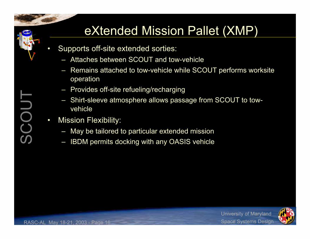
eXtended Mission Pallet (XMP)• Supports off-site extended sorties:
– Attaches between SCOUT and tow-vehicle– Remains attached to tow-vehicle while SCOUT performs worksite
operation– Provides off-site refueling/recharging– Shirt-sleeve atmosphere allows passage from SCOUT to tow-
vehicle• Mission Flexibility:
– May be tailored to particular extended mission– IBDM permits docking with any OASIS vehicle
RASC-AL May 18-21, 2003 - Page 17
SC
OU
T
University of MarylandSpace Systems Design
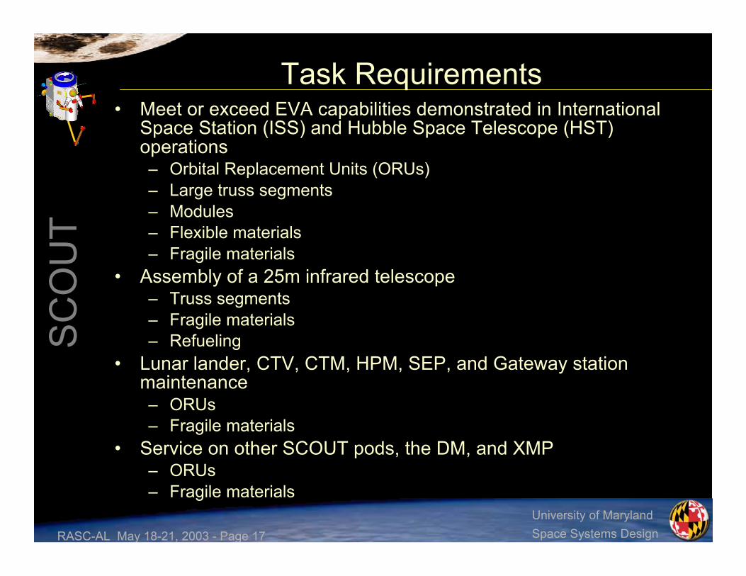
Task Requirements• Meet or exceed EVA capabilities demonstrated in International
Space Station (ISS) and Hubble Space Telescope (HST)operations– Orbital Replacement Units (ORUs)– Large truss segments– Modules– Flexible materials– Fragile materials
• Assembly of a 25m infrared telescope– Truss segments– Fragile materials– Refueling
• Lunar lander, CTV, CTM, HPM, SEP, and Gateway stationmaintenance– ORUs– Fragile materials
• Service on other SCOUT pods, the DM, and XMP– ORUs– Fragile materials

RASC-AL May 18-21, 2003 - Page 18
SC
OU
T
University of MarylandSpace Systems Design
Dexterous Manipulator Design• Task arms are modeled after 8-DOF Ranger Telerobotic
Shuttle Experiment arm– Trade study found two arms to be the best choice
• One arm did not provide the ability to grasp the hardware beingremoved while removing bolts and latches
• Three arms brought a concern about the interference of the arms witheach other and with the human arms due to intersecting workenvelopes
– Uses interchangeable end effectors for task completion• Maximum of eight end effectors on SCOUT• End effectors will be predetermined prior to sortie
• Grapple arm is a modified version of the task arm– Has a pitch joint at the wrist and is longer than the task arm– Uses either a universal gripping end effector or a foot restraint
interface end effector– Laser rangefinder is mounted on the grapple arm elbow

RASC-AL May 18-21, 2003 - Page 19
SC
OU
T
University of MarylandSpace Systems Design
Example End Effector Set• Bare Bolt Drive (BBD) end effector
– Drive bolts for the insertion and extraction of ORUs and theassembly of truss structures
• Parallel Jaw Mechanism (PJM) end effector– ORU grasping interfaces referenced from the ISS Robotic Systems
Integration Standards (JSC-37996)– Different “fingers” depending upon the grasping surface– Hand-over-hand (HOH) fingers
• Conceptual design that has the ability to grip several different itemswith set dimensions and shapes
• Found on the grapple arm and task arms• Used for gripping the worksite and non-thrusting maneuvers
• Microconical end effector (MEE)– ORU grasping interfaces referenced from the ISS Robotic Systems
Integration Standards (JSC-37996)– Used to grip microconical interfaces and micro fixtures found on
ORUs less than 600kg• End effectors are stored on tool posts found on both the sides
and underneath SCOUT

RASC-AL May 18-21, 2003 - Page 20
SC
OU
T
University of MarylandSpace Systems Design
Comparison of Tool Sets
PJMRigidizing tether or personal foot restraintAttach to worksite*
PJMGloved handsPull and rotateswitches
PJMGloved handsUsepliers/wrenches
BBD/PJMPistol grip tool or power ratchet toolDrive a gearPJMGloved handsTighten a tetherBBDEssex ratchet or ISS ratchetUse a ratchetPJMGloved handsTighten a latch
PJMGloved hand with specialized toolMate/demateconnectors
PJMGloved handsHold a handle
BBDRight angle drive with sockets and multi-setting torque limiter or cheater barDrive bolts
Robotic ToolHuman ToolActivity
O’Hara, John M. et al. Extravehicular Activities Limitations Study. ( all except * )

RASC-AL May 18-21, 2003 - Page 21
SC
OU
T
University of MarylandSpace Systems Design
Exterior Features
RMS Grapple FixtureEscape System
IBDM
Star Tracker
Ka-Band
UHF
Radiator
Grapple Arm
Laser Rangefinder
Radiator
Nitrogen QuadHydrazine
Triad
Single Hydrazine
Handrail
Helmet/Heads-Up-Display(HUD)
Human AX-5 Arms
Tool Posts
ExternalCamera
Task Arms
Mini-Workstation
Front View Rear View
Lights ExternalCamera

RASC-AL May 18-21, 2003 - Page 22
SC
OU
T
University of MarylandSpace Systems Design
Secondary Egress / Bailout (SHEEP)
Viewing window
Hand Controller
Spacesuit Arms
SAFER-typepropulsion
system
Softexpandable
body
• Current bailout design is anexternally expandable hybridspacesuit, to be known as theSCOUT Hybrid Expandable EscapePod (SHEEP)
– Hybrid design of the current NASAbailout ball, and the past Rockwellconceptual design of the RibStiffened Expandable EscapeSystem (RSEES)
– Escape Pod would be containedwithin a canister that is located onthe outside of SCOUT
– In the event of an emergency, thecrewmember would deploy thespacesuit, climb in, close the suit,and detach from SCOUT
– Allows the crewmember minimal useof their hands in order to control thepropulsion device and translatealong EVA handrails
– Provide crew member with 3 hrs ofemergency air (back-up fromSCOUT)

RASC-AL May 18-21, 2003 - Page 23
SC
OU
T
University of MarylandSpace Systems Design
Contoured Hull• The contoured torso hull will be place on the relative front of SCOUT and be
aligned with the relative top of the vehicle• The design of the torso hull was based off the torso of other hard suits, more
precisely the JSC Mark III and Ames AX-5• Combination of two rotary seals will be used to accommodate the varying
shoulder berths and sizes of the wide range of users• Current design for spacesuit arms
and gloves• Modeled after the NASA Ames
AX-5 suit arms• Shuttle Transport System
(STS) Extravehicular MobilityUnit (EMU) gloves
• Development of the AX-5 suit isbased on the capability of providingthe crewmember with a zero pre-breathe mission through anoperating pressure of 8.3psi

RASC-AL May 18-21, 2003 - Page 24
SC
OU
T
University of MarylandSpace Systems Design
Internal Layout
Front View Rear View Side View
Foot restraint locations
StorageBox
InternalCamera
EscapeHatch
PressureControl
CO2/AirSystem
WasteCollectionSystem
HandControllers
Computers
Touch ScreenMonitors
KeyboardFire Extinguisher

RASC-AL May 18-21, 2003 - Page 25
SC
OU
T
University of MarylandSpace Systems Design
Internal Volume Constraints• Major volume requirements designed
into the cabin layout
– Minimal volume required toaccommodate a 95% American male
• 0.72m x 0.71m x 0.172m• Internal components placed around
this volume
– Minimal volume required for acontrolled tumble
• Sphere with 1.22m diameter• Needed to flip over within SCOUT

RASC-AL May 18-21, 2003 - Page 26
SC
OU
T
University of MarylandSpace Systems Design
Worksite Interaction• Heads-Up Display (HUD)
– Used for display of pertinent informationdealing with
• Flight control• Robotic control• General SCOUT system
• Hand Controllers– Two 3-DOF controllers used for
translation and rotation control of• Manual flight• Operation of the task arms
• AX-5 Arm and Glove Sensors– Used to control task arms– Activated/deactivated by voice command
• Voice Recognition– System utilizes pre-allocated
communications hardware with thecomputers to process voice commands
– Allows for both coarse and fine control ofdexterous manipulators
HUD
Hand Controllers

RASC-AL May 18-21, 2003 - Page 27
SC
OU
T
University of MarylandSpace Systems Design
Crew Member Orientation• Foot Restraints – Floor
– Operation used for• AX-5 suit arm task work• Glove Sensors• Voice activation
• Foot Restraints – Back Wall– Operation used for
• Hand controllers• Voice activation

RASC-AL May 18-21, 2003 - Page 28
SC
OU
T
University of MarylandSpace Systems Design
Command, Control, and Comm Station• Two Touch Screen Monitors
– 15in display– Mass: 7.3kg– Peak Power: 26W– Accepts both HDTV and
computer input– Primarily used as a
reconfigurable computer displayduring system monitoring andvideo communication
• Keyboard• Internal Camera
– Used for real-time videoconferencing
Comm Station
Touch Screen Monitors
KeyboardCamera

RASC-AL May 18-21, 2003 - Page 29
SC
OU
T
University of MarylandSpace Systems Design
Life Support Systems Flowchart
CabinPressureControl
Panel (PCP)
Air Tanks
Overboard Vent
Charcoal Bed Metox
Condensing HeatExchanger
Waterin
To Gateway
Waste WaterTank
WasteCollectionSystem
Waterout
57kPa (8.3psi)
43% O2 / 57% N2
20.7MPa(3000psi)
Filter
Legend:
- Air Systems - Vacuum - Gateway - Waste - Pumps - Fan
RASC-AL May 18-21, 2003 - Page 30
SC
OU
T
University of MarylandSpace Systems Design
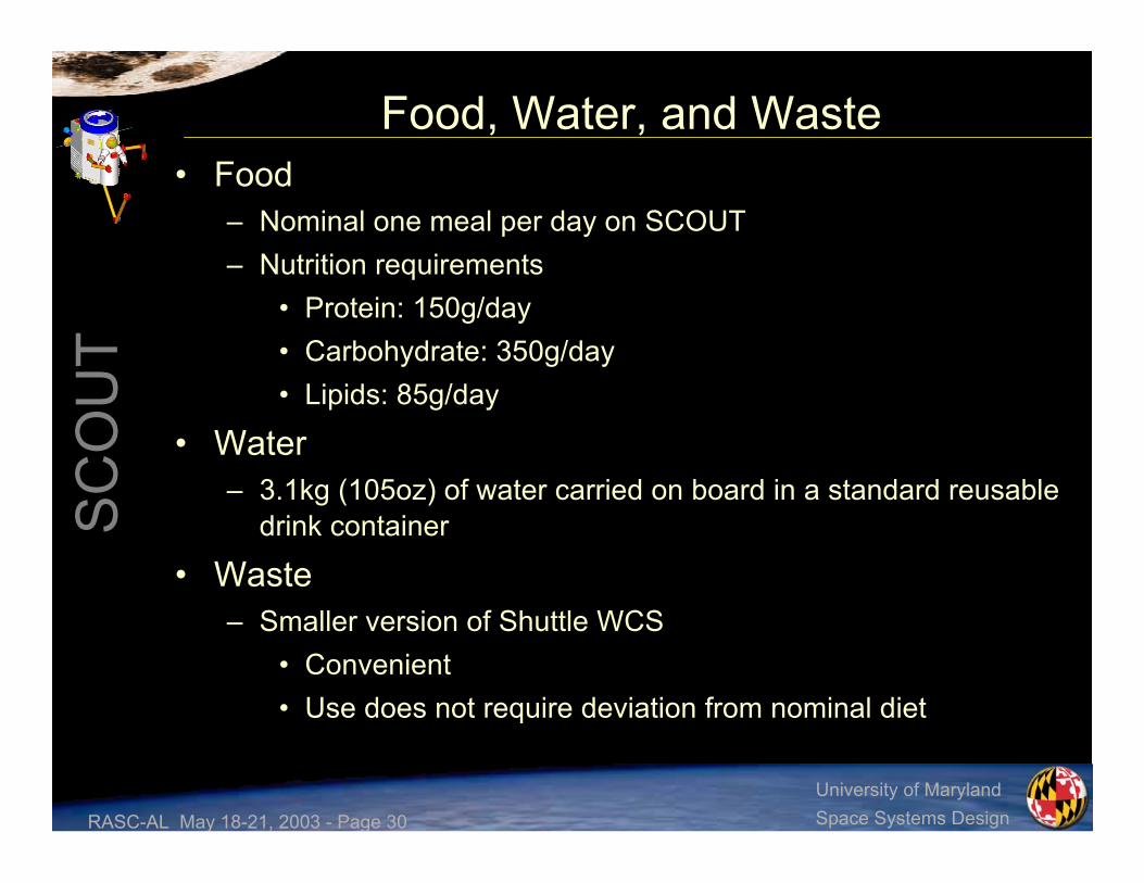
Food, Water, and Waste• Food
– Nominal one meal per day on SCOUT– Nutrition requirements
• Protein: 150g/day• Carbohydrate: 350g/day• Lipids: 85g/day
• Water– 3.1kg (105oz) of water carried on board in a standard reusable
drink container
• Waste– Smaller version of Shuttle WCS
• Convenient• Use does not require deviation from nominal diet

RASC-AL May 18-21, 2003 - Page 31
SC
OU
T
University of MarylandSpace Systems Design
Atmosphere• Air Systems provides nominal 20.5 hours; 41 hours as absolute
maximum– One oxygen tank is emergency backup
• Operating pressure 57kPa (8.3psi), 43% O2 / 57% N2
• R = ppN2-bloodstream/Patm = 0.65 (zero pre-breathe)R Value for Various Nitrogen Partial Pressures of Stations Hosting SCOUT
2
Gateway:
ppN2 = 5.4, R = 0.65
ISS: ppN2 = 11.6,
R = 1.39
0
0.2
0.4
0.6
0.8
1
1.2
1.4
1.6
1.8
2
0 2 4 6 8 10 12 14 16ppN2
R
Acceptable below this lineIdeal below this line

RASC-AL May 18-21, 2003 - Page 32
SC
OU
T
University of MarylandSpace Systems Design
Overall Structural Design• Hexagonal Pressure Hull
– Load-bearing aluminum panelsincorporating Micrometeoroid (MM) andOrbital Debris (OD) protection
– Stringers to transfer panel loads andserve as hard attachment points forShuttle launching
• Outer Frame– Load-bearing aluminum panels with MM
and OD protection– House external tanks and electronics– Back panel hinged for Li-Ion Battery
replacement and Power Distribution Unit(PDU) servicing
• Main mechanisms– International Berthing and
Docking Mechanism (IBDM)– Dexterous Manipulators– Remote Manipulator System (RMS)

RASC-AL May 18-21, 2003 - Page 33
SC
OU
T
University of MarylandSpace Systems Design
Launch Vehicle Integration• Using Spacelab Logistics
Pallet (SLP) with 5 pointattachment:– 2 sill fittings ±X and ±Z
loads– 2 sill fittings ±Z loads– 1 keel fitting ±Y loads
• Other SCOUT, DockingModule (DM) and eXtendedMission Pallet (XMP)attached to pallet similarly
RASC-AL May 18-21, 2003 - Page 34
SC
OU
T
University of MarylandSpace Systems Design
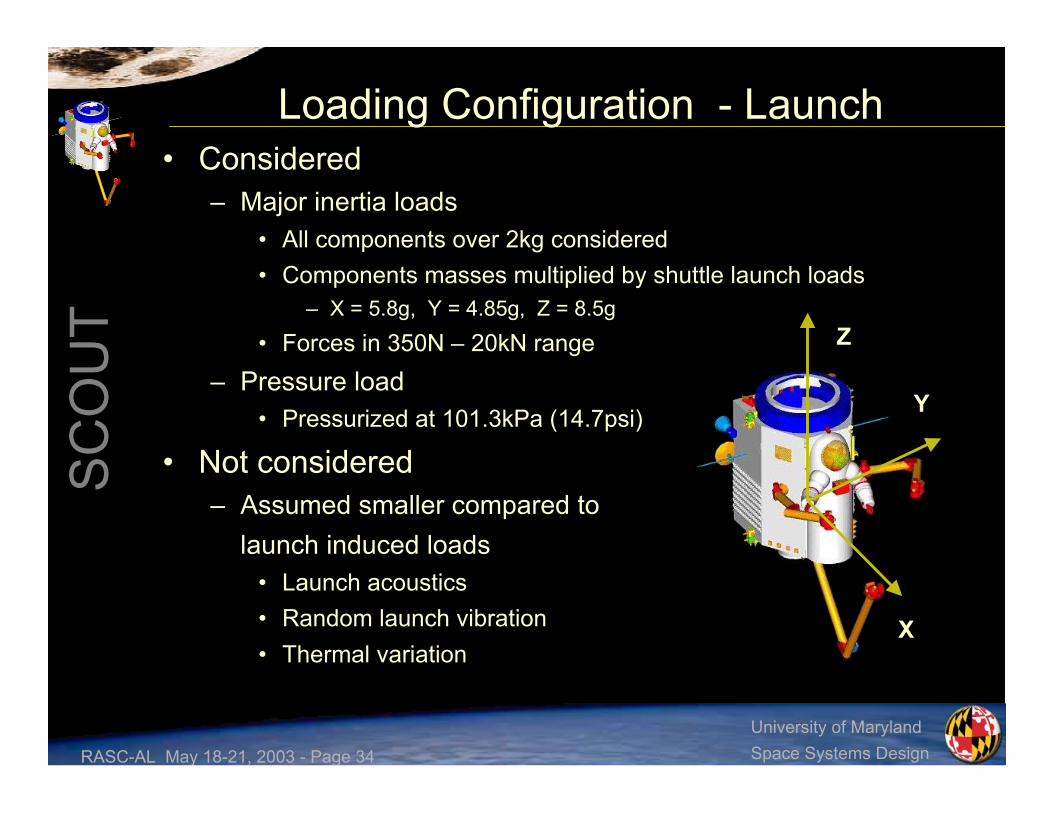
Loading Configuration - Launch• Considered
– Major inertia loads• All components over 2kg considered• Components masses multiplied by shuttle launch loads
– X = 5.8g, Y = 4.85g, Z = 8.5g• Forces in 350N – 20kN range
– Pressure load• Pressurized at 101.3kPa (14.7psi)
• Not considered– Assumed smaller compared to
launch induced loads• Launch acoustics• Random launch vibration• Thermal variation
Z
Y
X
RASC-AL May 18-21, 2003 - Page 35
SC
OU
T
University of MarylandSpace Systems Design
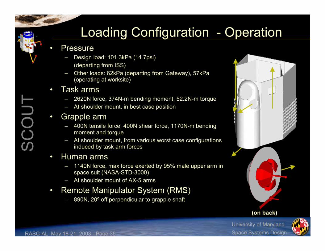
Loading Configuration - Operation• Pressure
– Design load: 101.3kPa (14.7psi)(departing from ISS)
– Other loads: 62kPa (departing from Gateway), 57kPa(operating at worksite)
• Task arms– 2620N force, 374N-m bending moment, 52.2N-m torque– At shoulder mount, in best case position
• Grapple arm– 400N tensile force, 400N shear force, 1170N-m bending
moment and torque– At shoulder mount, from various worst case configurations
induced by task arm forces
• Human arms– 1140N force, max force exerted by 95% male upper arm in
space suit (NASA-STD-3000)– At shoulder mount of AX-5 arms
• Remote Manipulator System (RMS)– 890N, 20º off perpendicular to grapple shaft
(on back)

RASC-AL May 18-21, 2003 - Page 36
SC
OU
T
University of MarylandSpace Systems Design
Loading Configuration - Other• Worksite transfer
– Thrusters forces on the order of 1N and 6N
• Docking– IBDM docking loads ~120N
• Maximum docking velocity = 0.06m/s• Assumed 1 second impulse load
– Berthing, if using RMS• Already accounted for in operational loading configuration
• Quantification of loads resulted in analysis of onlytwo configurations– Shuttle launch / abort– Worksite operation
RASC-AL May 18-21, 2003 - Page 37
SC
OU
T
University of MarylandSpace Systems Design
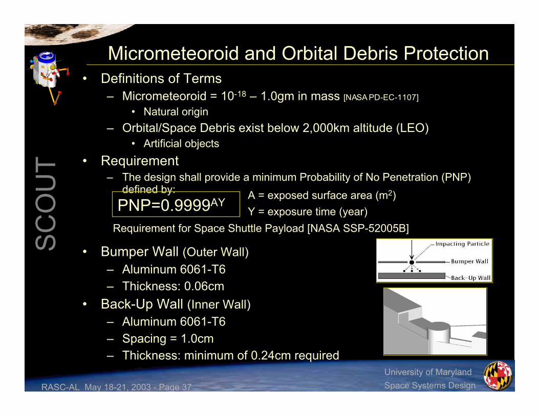
Micrometeoroid and Orbital Debris Protection• Definitions of Terms
– Micrometeoroid = 10-18 – 1.0gm in mass [NASA PD-EC-1107]
• Natural origin– Orbital/Space Debris exist below 2,000km altitude (LEO)
• Artificial objects• Requirement
– The design shall provide a minimum Probability of No Penetration (PNP)defined by:
• Bumper Wall (Outer Wall)– Aluminum 6061-T6– Thickness: 0.06cm
• Back-Up Wall (Inner Wall)– Aluminum 6061-T6– Spacing = 1.0cm– Thickness: minimum of 0.24cm required
Requirement for Space Shuttle Payload [NASA SSP-52005B]
A = exposed surface area (m2)Y = exposure time (year)PNP=0.9999AY
RASC-AL May 18-21, 2003 - Page 38
SC
OU
T
University of MarylandSpace Systems Design
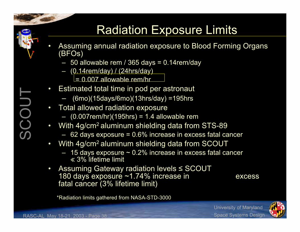
Radiation Exposure Limits• Assuming annual radiation exposure to Blood Forming Organs
(BFOs)– 50 allowable rem / 365 days = 0.14rem/day– (0.14rem/day) / (24hrs/day)
= 0.007 allowable rem/hr• Estimated total time in pod per astronaut
– (6mo)(15days/6mo)(13hrs/day) =195hrs• Total allowed radiation exposure
– (0.007rem/hr)(195hrs) = 1.4 allowable rem• With 4g/cm2 aluminum shielding data from STS-89
– 62 days exposure = 0.6% increase in excess fatal cancer• With 4g/cm2 aluminum shielding data from SCOUT
– 15 days exposure ~ 0.2% increase in excess fatal cancer≪ 3% lifetime limit
• Assuming Gateway radiation levels ≤ SCOUT180 days exposure ~1.74% increase in excessfatal cancer (3% lifetime limit)
*Radiation limits gathered from NASA-STD-3000

RASC-AL May 18-21, 2003 - Page 39
SC
OU
T
University of MarylandSpace Systems Design
Radiation Protection• Panels that need extra radiation protection
– Front, extra 3.23g/cm2
– Left Front, extra 2.42g/cm2
– Right Front, extra 2.23g/cm2
• These numbers are to meet the requirement of having radiationprotection of 4g/cm2
• The current plan for SCOUT for the Gateway missions is tohave these panels as extra aluminum panels
• This increases the margin of safety (MOS) for those panels ofthe spacecraft
• All other areas of the spacecraft have enough mass andsurface area of other components that no extra radiationprotection is required
• With future innovation in radiation protection, the front 3 panelscan be outfitted with any material that will meet the abovecriteria
• Also for missions that may require more stringent radiationrequirements, SCOUT can have panels added in locationsrequiring more protection
RASC-AL May 18-21, 2003 - Page 40
SC
OU
T
University of MarylandSpace Systems Design
Calculations Overview• Calculations were done to determine the thickness of
the SCOUT panels• Three different situations were analyzed
– Pressurization loading– Operational loading– Launch loading
• Axial direction• Shear direction
• Each system was optimized to the minimumthickness based on the lowest non-negative marginof safety (MOS) that was acceptable for allrequirements
• Micrometeoroid, orbital debris and radiationprotection were taken into account for thesecalculations

RASC-AL May 18-21, 2003 - Page 41
SC
OU
T
University of MarylandSpace Systems Design
Panel StructureFactor of Safety – 2.0 : Primary
Axial LaunchLoading0.047275132Alum 6061-
T626.3Right Front7
RadiationProtection4.14275136Alum 6061-
T633.6Right FrontExtra8
Axial LaunchLoading0.019275135Alum 6061-
T621.9Left BackPressure6
RadiationProtection5.44275131Alum 6061-
T636.5Left FrontExtra5
Axial LaunchLoading0.048275131Alum 6061-
T623.5Left Front4
RadiationProtection27.1275124Alum 6061-
T648.6Front Extra3
OperationalLoading0.042275124Alum 6061-
T611.3Front2
Axial LaunchLoading0.057275136Alum 6061-
T613.7Top1
Based OnMOSYield Stress(MPa)
DesignLoad (MPa)MaterialMass
(kg)Name#

RASC-AL May 18-21, 2003 - Page 42
SC
OU
T
University of MarylandSpace Systems Design
Panel StructureFactor of Safety – 2.0 : Primary
Axial LaunchLoading0.052275132Alum
6061-T611.3Left Back14
Axial LaunchLoading0.019275135Alum
6061-T613.8BackPressure13
Axial LaunchLoading0.443275131Alum
6061-T611.3Right Back12
Axial LaunchLoading0.034275131Alum
6061-T626.5Bottom11
Not LoadBearingN/A275124Alum
6061-T619.4Back Panel10
Axial LaunchLoading0.019275124Alum
6061-T621.9Right BackPressure9
Based OnMOSYield
Stress(MPa)
DesignLoad (MPa)MaterialMass
(kg)Name#

RASC-AL May 18-21, 2003 - Page 43
SC
OU
T
University of MarylandSpace Systems Design
Thermal Control• Interior Environment
– The interior of the pod, specifically thepressure hull, will be maintained thermallyby utilizing a series of different systems
• Heat Exchanger: transfer heat fromcirculating ‘cabin’ air to working fluid in heatpipe
• Heat Pipe: transport heat to radiator usingfreon via capillary action
• Radiator: radiate heat to space• Heater: trim temperature during colder
conditions• Battery Subsystem
– The batteries will be controlled thermally byan active radiator system
• Radiator: radiate heat generated frombattery packs using a system of coolingloops and a working fluid consisting of freon
• Pump: circulate freon through radiator• Insulation will be used to keep the fuel
tanks at nominal temperature with Multi-Layer Insulation (MLI)

RASC-AL May 18-21, 2003 - Page 44
SC
OU
T
University of MarylandSpace Systems Design
Propulsion Tanks• Requirements for tanks
0.0120.030.32Volume of the Tank (m3)
0.090.100.17Inner Radius (m)
272.227Max. Operating Pressure (Mpa)
NitrogenPressurant
HydrazinePropellant
NitrogenPropellant
Hydrazine Propellant
t = 0.002m
L = 0.33m
Lt = 0.5m
Mass = 1.8kg
Nitrogen Pressurant
t = 0.0071m
L = 0.09m
Lt = 0.3m
Mass = 1.7kg
Nitrogen Propellant
t = 0.013m
L = 1.6m
Lt = 2m
Mass = 98kg
LtL
t* 2 tanks of each per SCOUT

RASC-AL May 18-21, 2003 - Page 45
SC
OU
T
University of MarylandSpace Systems Design
Pressure Lines and Tank Attachments• Pressure lines
– A similar analyses as the tankage MER analysis has been conducted with a factor ofsafety of 4
• Diaphragms with thickness t = 0.002m
• Tank Structural Attachments– Pads and Rods/Hooks– Estimated 2% of the supported weight
• Support for Nitrogen Propellant = 3.78kg• Support for Hydrazine Propellant = 0.10kg• Support for Nitrogen Pressurant = 0.63kg
52015Length of the Lines (estimated) (m)
275Mass of the Lines (kg)
0.0050.0050.005Inner Radius (m)
272.22.7Max. Operating Pressure (Mpa)
Nitrogen HighPressure Lines
Hydrazine LowPressure Lines
Nitrogen LowPressure Lines
Pads
Rods
= 0.234kgMd=ρVdVd=(4/3)π[ri3-(ri-0.002)3]

RASC-AL May 18-21, 2003 - Page 46
SC
OU
T
University of MarylandSpace Systems Design
Tank and Thruster Placement• 16, 1N Nitrogen thrusters
– For contamination-critical sites
– 4 quads
• 16, 6N Hydrazine thrusters– For non-sensitive sites
– 4 triads
– 4 singles
NitrogenPressurant Tank
* One on each side
Hydrazine Propellant Tank
* One on each side
NitrogenPropellant Tanks

RASC-AL May 18-21, 2003 - Page 47
SC
OU
T
University of MarylandSpace Systems Design
Catalyst Bed Heaters
Valve Heaters Line Heaters
(T16)
(T14)
(T15)
(T13)
(T8)
(T6)
(T7)
(T5)
(T4)
(T2)
(T3)
(T1)
(T12)
(T10)
(T11)
(T9)
Bottom Left Panel
Bottom Right Panel
TopLeft Panel
TopRight Panel
Fill and Drain ValveFlow Control Valve Normally ClosedFlow Control Valve Normally OpenFilterThrust Chamber Valve (TCV)Valve Branch AValve Branch BHeaterPressureTemperatureThrusterIsolation Valve
(P)(T)
GN2GN2
(P)
(T) (T)
(P)
1A 4A
3A6A
6B
4B1B
3B
25
N2H4 N2H4
(P)
(T)
(T)
(P)
Hydrazine System Schematic
RASC-AL May 18-21, 2003 - Page 48
SC
OU
T
University of MarylandSpace Systems Design
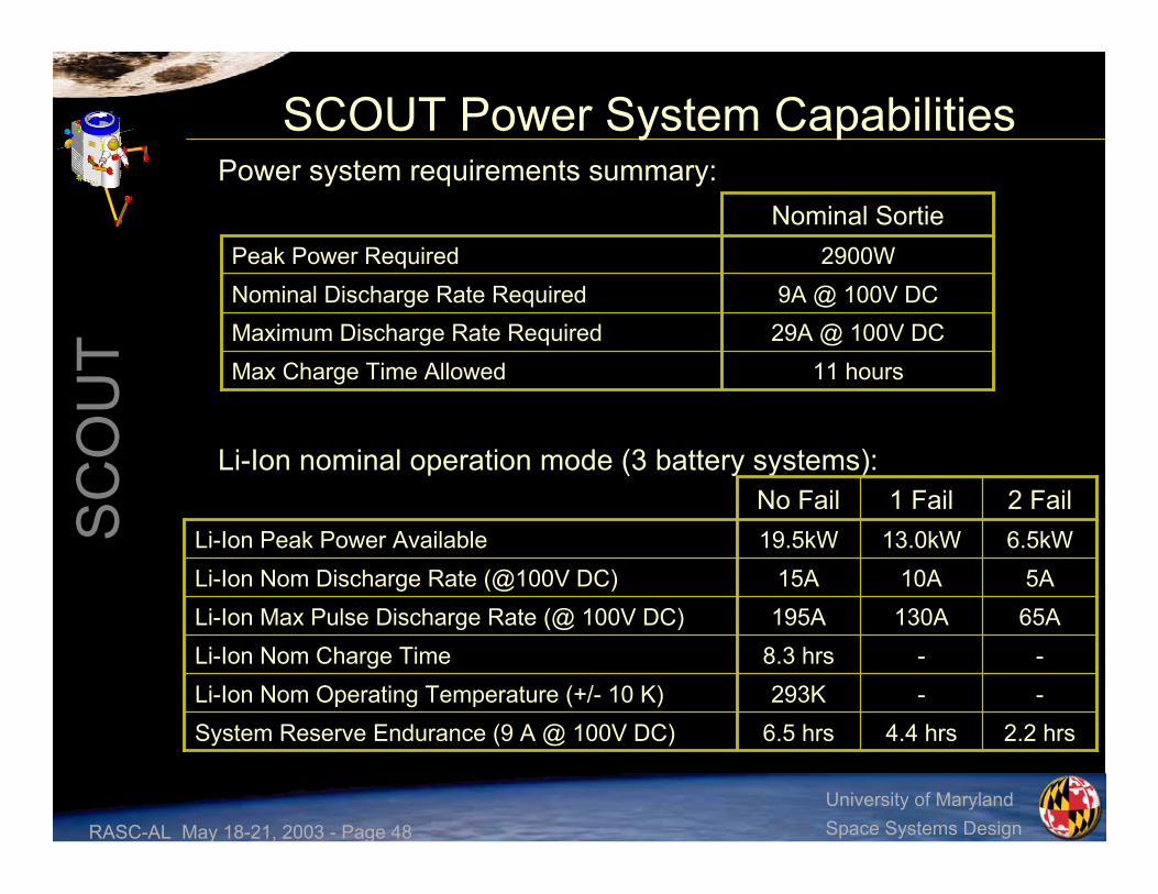
SCOUT Power System CapabilitiesPower system requirements summary:
Li-Ion nominal operation mode (3 battery systems):
Nominal Sortie
11 hoursMax Charge Time Allowed29A @ 100V DCMaximum Discharge Rate Required9A @ 100V DCNominal Discharge Rate Required
2900WPeak Power Required
--293KLi-Ion Nom Operating Temperature (+/- 10 K)2.2 hrs4.4 hrs6.5 hrsSystem Reserve Endurance (9 A @ 100V DC)
--8.3 hrsLi-Ion Nom Charge Time65A130A195ALi-Ion Max Pulse Discharge Rate (@ 100V DC)5A10A15ALi-Ion Nom Discharge Rate (@100V DC)
6.5kW13.0kW19.5kWLi-Ion Peak Power Available2 Fail1 FailNo Fail

RASC-AL May 18-21, 2003 - Page 49
SC
OU
T
University of MarylandSpace Systems Design
Solid StateRecorderSolid StateRecorderLi-Ion Battery
Power Distribution Block Diagram
Firewire Data BusFirewire Data Bus
Legend:FDCC - Flight & Data Control Computer - Primary Avionics Components - Critical Crew Survival Systems - Mission Systems - Data Transfer - Power Transfer
Power DistributionUnit A
Docking ModulePower Resupply
Power DistributionUnit B
Power DistributionUnit C
Robotic Control
Low PowerComponents
FDCCFDCCFDCC
CompactPCI Bus
Standard PowerSystems (28 VDC)
• PDU:– Modulated for easy reconfiguration to meet
specific requirements– Capable of providing 97% efficiency at 1500W– Space qualified on several spacecraft

RASC-AL May 18-21, 2003 - Page 50
SC
OU
T
University of MarylandSpace Systems Design
Avionics Top-Level Block Diagram
Robotic Control
Communication/Video System
Propulsion System
Attitude Sensors
Astronaut Interface
Life Support Sensors
Firewire Data BusFirewire Data Bus
FDCCFDCCFDCC
CompactPCI Bus
Thermal Control
Power Distribution
ComputerDisplay
ComputerDisplay
Solid StateRecorder
Solid StateRecorder
Legend:FDCC - Flight & Data Control Computer - Primary Avionics Components - Critical Crew Survival Systems - Flight Control Systems - Mission Systems

RASC-AL May 18-21, 2003 - Page 51
SC
OU
T
University of MarylandSpace Systems Design
Communication Block DiagramUHFOmni
GimbaledKa-Band
Transponder
SensorData
Video System
Crew Interface - Hand Controllers - Switches - Voice
Flightcomputers
PowerAmplifierFDCC
FDCCFDCC
Video Displays AntennaSwitch
Diplexer
AntennaSwitch
Diplexer

RASC-AL May 18-21, 2003 - Page 52
SC
OU
T
University of MarylandSpace Systems Design
Processor Selection• Several radiation hardened processors were compared on the basis of
power consumption and performance• RAD750 is the most capable radiation hardened processor anticipated
to be in use during the SCOUT mission timeline– MTBF >390K hours = Reliability of >99.9% over 6 month mission
• SCOUT nominal operation distributes load between two FDCCs– Third FDCC for backup– Each FDCC is capable of individually supporting SCOUT tasks
BAE Systems
RASC-AL May 18-21, 2003 - Page 53
SC
OU
T
University of MarylandSpace Systems Design
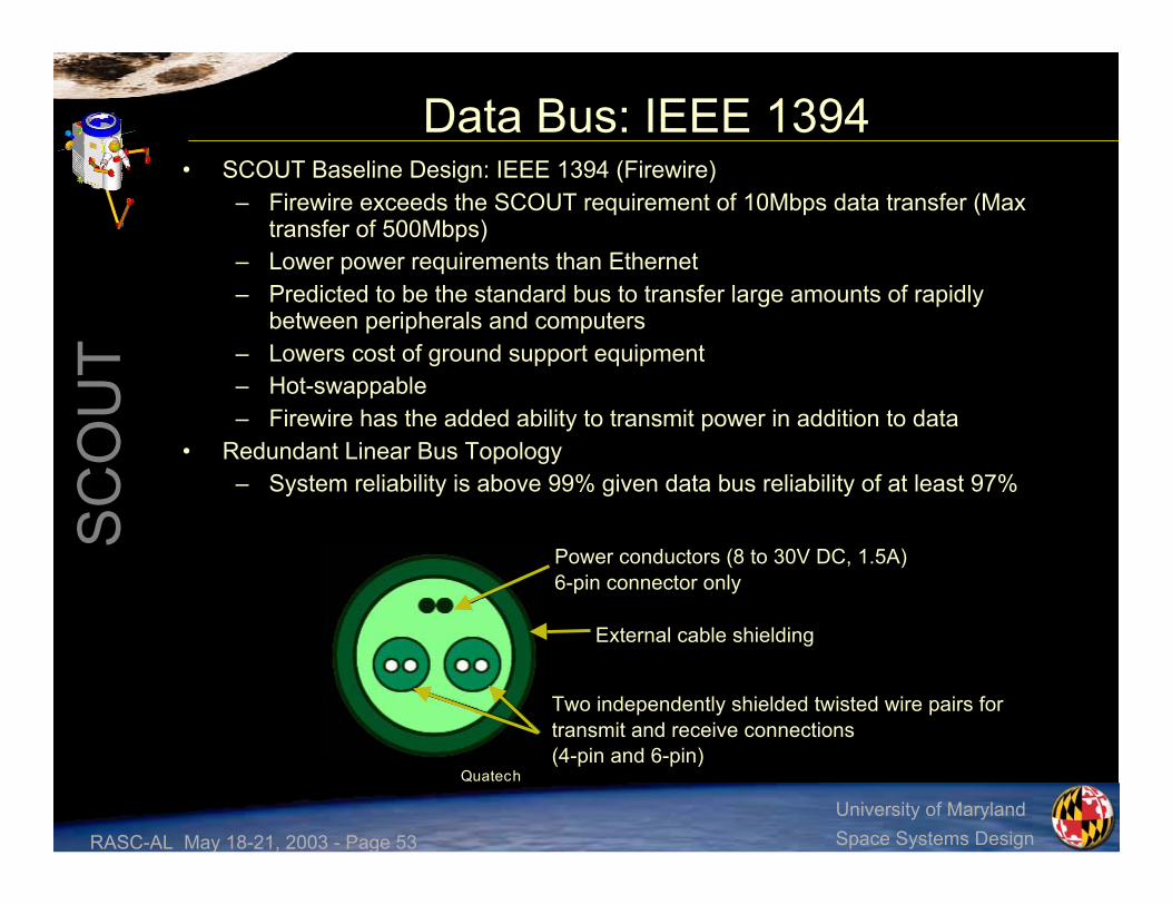
Data Bus: IEEE 1394• SCOUT Baseline Design: IEEE 1394 (Firewire)
– Firewire exceeds the SCOUT requirement of 10Mbps data transfer (Maxtransfer of 500Mbps)
– Lower power requirements than Ethernet– Predicted to be the standard bus to transfer large amounts of rapidly
between peripherals and computers– Lowers cost of ground support equipment– Hot-swappable– Firewire has the added ability to transmit power in addition to data
• Redundant Linear Bus Topology– System reliability is above 99% given data bus reliability of at least 97%
Quatech
Power conductors (8 to 30V DC, 1.5A)6-pin connector only
External cable shielding
Two independently shielded twisted wire pairs fortransmit and receive connections(4-pin and 6-pin)

RASC-AL May 18-21, 2003 - Page 54
SC
OU
T
University of MarylandSpace Systems Design
Video Guidance Sensor• Video Guidance Sensor (VGS) used
for autonomous docking• Two active sensors located on
SCOUT• Passive targets mounted on each
IBDM on the docking module• Computer controlled maneuvers
allow for better accuracies, moreefficient maneuvering and a “softer”dock
• Originally developed as part ofNASA’s Automated Rendezvousand Capture (AR&C) system atMarshall Space Flight Center
• VGS provides all relative positionand attitude measurements (6-DOF)to the Guidance, Navigation, andControl (GN&C) system
Retro-Reflector Clusters
Active SensorPassive Target
RASC-AL May 18-21, 2003 - Page 55
SC
OU
T
University of MarylandSpace Systems Design
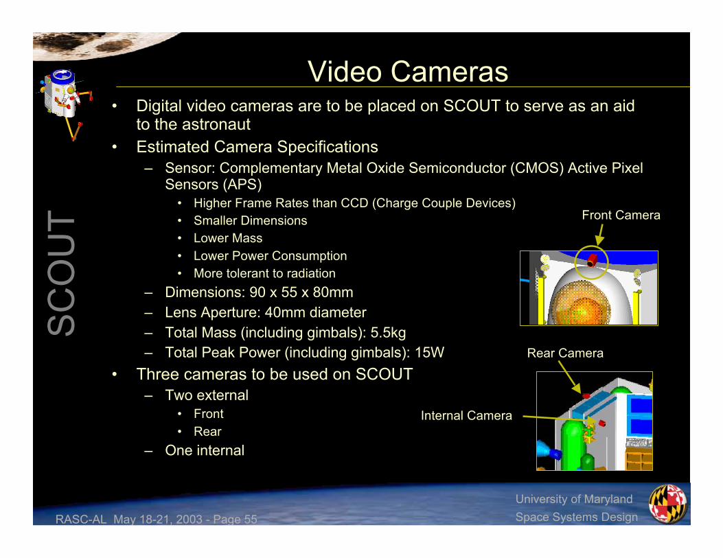
Video Cameras• Digital video cameras are to be placed on SCOUT to serve as an aid
to the astronaut• Estimated Camera Specifications
– Sensor: Complementary Metal Oxide Semiconductor (CMOS) Active PixelSensors (APS)
• Higher Frame Rates than CCD (Charge Couple Devices)• Smaller Dimensions• Lower Mass• Lower Power Consumption• More tolerant to radiation
– Dimensions: 90 x 55 x 80mm– Lens Aperture: 40mm diameter– Total Mass (including gimbals): 5.5kg– Total Peak Power (including gimbals): 15W
• Three cameras to be used on SCOUT– Two external
• Front• Rear
– One internal
Front Camera
Rear Camera
Internal Camera

RASC-AL May 18-21, 2003 - Page 56
SC
OU
T
University of MarylandSpace Systems Design
Costing• Cost based on heuristic formulas at the vehicle level for both
SCOUTs, the docking module, and the XMP• SCOUTs
– Non-recurring Cost ($M) = $1180 Million– 1st Unit Production = $87 Million– 2nd Unit Production = $70 Million
• Docking Module– Non-recurring Cost ($M) = $260 Million– 1st Unit Production = $71 Million
• XMP– Non-recurring Cost ($M) = $142 Million– 1st Unit Production = $35 Million
Total = $1850 Million

RASC-AL May 18-21, 2003 - Page 57
SC
OU
T
University of MarylandSpace Systems Design
Discussion of External Work Stations
Extravehicular MobilityUnit (EMU) and
Manned ManeuveringUnit (MMU)
Robonaut SCOUT
ILC Dover NASA Johnson Space Center

RASC-AL May 18-21, 2003 - Page 58
SC
OU
T
University of MarylandSpace Systems Design
System ComparisonSCOUTRobonautEMU w/MMU
N/A
N/A
N/A
Yes
Yes
Yes
Yes
Yes
No
25m
8hr
No
7hr + 0.5hrreserve
3g/cm2
No
No
No
No
No
Yes
120m
7hr
SHEEP/SAFER
11hr + 2hrreserve
4g/cm2
Yes
Yes
Yes
Yes
Yes
Yes
1000m
11hr
Bailout Systems
Life Support
Radiation Protection
2-Hand Operation
Single Person Op Capability
Autonomous Control
Human/Robotics Interaction
Teleoperation Control
On Site Human Intel
Max Sortie Distance
Max Sortie Duration

RASC-AL May 18-21, 2003 - Page 59
SC
OU
T
University of MarylandSpace Systems Design
SCOUT• SCOUT has a major advantage over both
EMU and Robonaut working togetherbecause:– Longer sortie duration and distance– No extra exertion for the astronaut– No need for pre-breathing– Room for astronaut to move in vehicle– Potential for long term excursions– Provides extra protection from deep space
environment• Radiation• Micrometeoroids• Thermal conditions
– Allows for use of robotic arms and humanarms together in a complementary manner
– Ability to maintain and repair GatewayStation and rest of SCOUT system

RASC-AL May 18-21, 2003 - Page 60
SC
OU
T
University of MarylandSpace Systems Design
Solution• SCOUT can handle the improvements necessary for
the space station emergency scenario– It is a single occupant vehicle– Needs minimal preparation time– Travels much faster than the RMS arm– Has the capabilities of three astronauts
• RMS operator = Grapple arm• Free-Floater = Task arms• RMS attached = AX-5 arms
– Allows for maximum work time due to• Low fatigue factor• Consumable availability
– Capabilities for day after day space construction
Revolutionary Solution = SCOUT

RASC-AL May 18-21, 2003 - Page 61
SC
OU
T
University of MarylandSpace Systems Design
The SCOUT Team• Avionics
– Aaron Hoskins– Will Miller– Oliver Sadorra– Greg Stamp
• Life Support and Human Factors– Katy Catlin– Avi Edery– John Hintz– Andrew Long– Alexandra Langley
• Loads, Structures, andMechanisms– Justin Richeson– Eric Rodriguez– Ernest Silva– Yudai Yoshimura
• Mission Planning and Analysis– Chris Bowen– Wendy Frank– Kirstin Hollingsworth– Sadie Michael– Jackie Reilly
• Power, Propulsion, and Thermal– Cagatay Aymergen– Matt Beres– Nathan Moulton– Christopher Work
• Systems Integration– Meghan Baker– Tom Christy– Jesse Colville– Robyn Jones– Lynn Pierson
RASC-AL May 18-21, 2003 - Page 62
SC
OU
T
University of MarylandSpace Systems Design
Outreach• March 6, 2003 – Preliminary Design Review• April 26, 2003 – Maryland Day• May 3, 2003 – Critical Design Review• May 12, 2003 – Aerospace Engineering
Department Briefing• May 13-14, 2003 – Aerospace Technology
Working Group conference

RASC-AL May 18-21, 2003 - Page 63
SC
OU
T
University of MarylandSpace Systems Design
Acknowledgements• Dr. Akin and Dr. Bowden for being our advisors for
this project• Brian Roberts for being one of our primary resources
throughout this design process• All of the people who came to give us feedback at
our Preliminary and Critical Design Reviews onMarch 6th and May 3rd
• Dr. Fourney and the Aerospace EngineeringDepartment at the University of Maryland for theirsupport

RASC-AL May 18-21, 2003 - Page 64
SC
OU
T
University of MarylandSpace Systems Design