t-rec-g.842-199704-i!!pdf-e
DESCRIPTION
)NTERWORKINGOF3$(NETWORKPROTECTIONARCHITECTURESTRANSCRIPT
INTERNATIONAL TELECOMMUNICATION UNION
)45 4 '����TELECOMMUNICATIONSTANDARDIZATION SECTOROF ITU
(04/97)
SERIES G: TRANSMISSION SYSTEMS AND MEDIA,DIGITAL SYSTEMS AND NETWORKS
Digital transmission systems – Digital networks – SDHnetwork characteristics
)NTERWORKING�OF�3$(�NETWORK�PROTECTIONARCHITECTURES
ITU-T Recommendation G.842(Previously CCITT Recommendation)

ITU-T G-SERIES RECOMMENDATIONS
42!.3-)33)/.�3934%-3�!.$�-%$)!��$)')4!,�3934%-3�!.$�.%47/2+3
For further details, please refer to ITU-T List of Recommendations.
INTERNATIONAL TELEPHONE CONNECTIONS AND CIRCUITS G.100–G.199
).4%2.!4)/.!,�!.!,/'5%�#!22)%2�3934%-
GENERAL CHARACTERISTICS COMMON TO ALL ANALOGUE CARRIER-TRANSMISSION SYSTEMS
G.200–G.299
INDIVIDUAL CHARACTERISTICS OF INTERNATIONAL CARRIER TELEPHONESYSTEMS ON METALLIC LINES
G.300–G.399
GENERAL CHARACTERISTICS OF INTERNATIONAL CARRIER TELEPHONESYSTEMS ON RADIO-RELAY OR SATELLITE LINKS AND INTERCONNECTIONWITH METALLIC LINES
G.400–G.449
COORDINATION OF RADIOTELEPHONY AND LINE TELEPHONY G.450–G.499
42!.3-)33)/.�-%$)!�#(!2!#4%2)34)#3
$)')4!,�42!.3-)33)/.�3934%-3
TERMINAL EQUIPMENTS G.700–G.799
DIGITAL NETWORKS G.800–G.899
General aspects G.800–G.809
Design objectives for digital networks G.810–G.819
Quality and availability targets G.820–G.829
Network capabilities and functions G.830–G.839
3$(�NETWORK�CHARACTERISTICS '���� '����
Telecommunications management network G.850–G.859
DIGITAL SECTIONS AND DIGITAL LINE SYSTEM G.900–G.999
General G.900–G.909
Parameters for optical fibre cable systems G.910–G.919
Digital sections at hierarchical bit rates based on a bit rate of 2048 kbit/s G.920–G.929
Digital line transmission systems on cable at non-hierarchical bit rates G.930–G.939
Digital line systems provided by FDM transmission bearers G.940–G.949
Digital line systems G.950–G.959
Digital section and digital transmission systems for customer access to ISDN G.960–G.969
Optical fibre submarine cable systems G.970–G.979
Optical line systems for local and access networks G.980–G.999
ITU-T RECOMMENDATION G.842
INTERWORKING OF SDH NETWORK PROTECTION ARCHITECTURES
Summary
This Recommendation provides specifications for the interworking of network protectionarchitectures. Specifically covered are single and dual node interconnection between MS-sharedprotection rings and SNCP rings of like or unlike types.
Source
ITU-T Recommendation G.842 was prepared by ITU-T Study Group 15 (1997-2000) and wasapproved under the WTSC Resolution No. 1 procedure on the 8th of April 1997.
ii Recommendation G.842 (04/97)
FOREWORD
ITU (International Telecommunication Union) is the United Nations Specialized Agency in the field oftelecommunications. The ITU Telecommunication Standardization Sector (ITU-T) is a permanent organ ofthe ITU. The ITU-T is responsible for studying technical, operating and tariff questions and issuingRecommendations on them with a view to standardizing telecommunications on a worldwide basis.
The World Telecommunication Standardization Conference (WTSC), which meets every four years,establishes the topics for study by the ITU-T Study Groups which, in their turn, produce Recommendationson these topics.
The approval of Recommendations by the Members of the ITU-T is covered by the procedure laid down inWTSC Resolution No. 1.
In some areas of information technology which fall within ITU-T’s purview, the necessary standards areprepared on a collaborative basis with ISO and IEC.
NOTE
In this Recommendation, the expression "Administration" is used for conciseness to indicate both atelecommunication administration and a recognized operating agency.
INTELLECTUAL PROPERTY RIGHTS
The ITU draws attention to the possibility that the practice or implementation of this Recommendation mayinvolve the use of a claimed Intellectual Property Right. The ITU takes no position concerning the evidence,validity or applicability of claimed Intellectual Property Rights, whether asserted by ITU members or othersoutside of the Recommendation development process.
As of the date of approval of this Recommendation, the ITU had/had not received notice of intellectualproperty, protected by patents, which may be required to implement this Recommendation. However,implementors are cautioned that this may not represent the latest information and are therefore strongly urgedto consult the TSB patent database.
ITU 1997
All rights reserved. No part of this publication may be reproduced or utilized in any form or by any means,electronic or mechanical, including photocopying and microfilm, without permission in writing from the ITU.
Recommendation G.842 (04/97) iii
CONTENTS
Page
1 Scope........................................................................................................................... 1
2 References................................................................................................................... 1
3 Terms and definitions ................................................................................................. 1
4 Abbreviations.............................................................................................................. 3
5 Interworking criteria/objectives.................................................................................. 4
5.1 Criteria for ring interworking with an MS-shared protection ring.............................. 4
6 Interworking architectures .......................................................................................... 5
6.1 Single node interconnection........................................................................................ 5
6.2 Dual node interconnection .......................................................................................... 5
6.2.1 Generalized architecture ................................................................................ 5
6.2.2 Ring interworking with an MS-shared protection ring.................................. 7
6.2.3 Ring interworking with an SNCP ring........................................................... 21
6.2.4 Multiple rings ................................................................................................ 32
7 Interworking among network layers ........................................................................... 32
8 Switch contention ....................................................................................................... 32

Recommendation G.842 (04/97) 1
Recommendation G.842
INTERWORKING OF SDH NETWORK PROTECTION ARCHITECTURES
(Geneva, 1997)1 Scope
This Recommendation describes mechanisms for interworking between network protectionarchitectures. The network protection architectures are described in Recommendation G.841.Interworking is described for single and dual node interconnection for exchanging traffic betweenrings. Each ring may be configured for MS-shared protection or for SNCP protection.
2 References
The following ITU-T Recommendations, and other references contain provisions which, throughreference in this text, constitute provisions of this Recommendation. At the time of publication, theeditions indicated were valid. All Recommendations and other references are subject to revision; allusers of this Recommendation are therefore encouraged to investigate the possibility of applying themost recent edition of the Recommendations and other references listed below. A list of the currentlyvalid ITU-T Recommendations is regularly published.
– ITU-T Recommendation G.803 (1997), Architecture of transport networks based on theSynchronous Digital Hierarchy (SDH).
– ITU-T Recommendation G.841 (1995), Types and characteristics of SDH networkprotection architectures.
– ITU-T Recommendation G.783 (1997), Characteristics of Synchronous Digital Hierarchy(SDH) equipment functional blocks.
3 Terms and definitions
NOTE – These definitions need to be reviewed with respect to the emerging Recommendation on SDHvocabulary.
This Recommendation defines the following terms.
3.1 drop-and-continue: A function within a ring node where traffic is both extracted from theworking channels on the ring (drop), and transmitted onwards on the ring (continue).
3.2 dual hubbed: Dual hubbed traffic can be routed to either or both of two central offices (orsimilar sites). Dual hubbed traffic is survivable under a failure of one of the two hubs.
3.3 dual node interconnection: An architecture between two rings where two nodes in eachring are interconnected.
3.4 hold-off time: The time that a protection switch controller waits after detecting a failurebefore initiating the switch.
3.5 path selector: Within an SNCP architecture, the node function that selects a tributary whichis extracted from the working channels arriving from one side of the node or from the other side ofthe node, according to path level criteria.
3.6 primary node: Within an MS-shared protection ring interworking architecture, the nodewhich provides the service selection and drop-and-continue functions for a tributary. Differenttributaries may have different designated primary nodes.

2 Recommendation G.842 (04/97)
3.7 propagation of switching: One protection switch leading to another. Propagation ofswitching is often, though not always, undesirable from a maintenance point of view.
3.8 ring interconnection: An architecture between two rings where one or more nodes in eachring are interconnected.
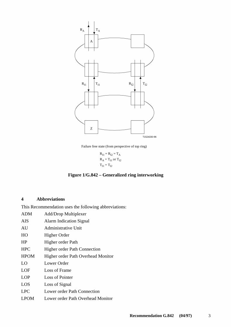
3.9 ring interworking: A network topology whereby two rings are interconnected at two nodeson each ring, and the topology operates such that a failure at either of these two nodes will not causeloss of any working traffic. This is illustrated in Figure 1.
3.10 secondary circuit: Within an MS-shared protection ring interworking architecture, this isthe alternate routing that traffic travelling from one ring to another follows. This alternate additionalrouting is used when the service circuit is interrupted.
3.11 secondary node: Within an MS-shared protection ring interworking architecture, the nodewhich provides the alternate interworking route for a tributary.
3.12 service circuit: Within an MS-shared protection ring interworking architecture, this is thepreferred original routing that traffic travelling from one ring to another normally follows.
3.13 service selector: Within an MS-shared protection ring architecture, the node function usedfor ring interworking. It selects traffic from either the channels arriving from one side of the node, orfrom traffic entering the ring, according to some criteria.
3.14 single node interconnection: An architecture between two rings where one node in eachring is interconnected.
3.15 termination node: The node (other than a primary or secondary node) where a tributaryenters or exits the ring.
Recommendation G.842 (04/97) 3
T1524330-96
RA
A
RI1
Z
TA
TI1 RI2 TI2
Failure free state (from perspective of top ring)
RI1 = RI2 = TA
RA = TI1 or TI2
TI1 = TI2
Figure 1/G.842 – Generalized ring interworking
4 Abbreviations
This Recommendation uses the following abbreviations:
ADM Add/Drop Multiplexer
AIS Alarm Indication Signal
AU Administrative Unit
HO Higher Order
HP Higher order Path
HPC Higher order Path Connection
HPOM Higher order Path Overhead Monitor
LO Lower Order
LOF Loss of Frame
LOP Loss of Pointer
LOS Loss of Signal
LPC Lower order Path Connection
LPOM Lower order Path Overhead Monitor

4 Recommendation G.842 (04/97)
MS Multiplex Section
SDH Synchronous Digital Hierarchy
SNC SubNetwork Connection
SNCP SubNetwork Connection Protection
SNC/I SubNetwork Connection Protection with Inherent Monitoring
SNC/N SubNetwork Connection Protection with Non-Intrusive Monitoring
STM(-N) Synchronous Transport Module (-N)
TIM Trace Identifier Mismatch
UNEQ Unequipped
VC Virtual Container
5 Interworking criteria/objectives
Interworking SDH protection architectures are meant to provide an even greater degree of protectionwithin a network. Some considerations for interworking criteria are as follows:
– end-to-end availability requirements;
– robustness against various failure events;
− implementation complexity and costs.
The following is a list of interworking objectives:
1) Ring interworking shall be accommodated in such a way that if two rings are connected atmore than one node each, a failure at one of these node shall not cause loss of any service.
2) It should be possible to avoid propagation of switching between interworking rings.
3) The ring shall be able to drop traffic at multiple nodes, i.e. working traffic can be dropped attwo, or more, nodes on a ring without compromising the ability to restore traffic that is dualhubbed (or any other traffic).
4) Ring interconnection may occur among multiple rings. Interconnection boundaries should bethe same for all similar instances of interworking between two ring types.
5.1 Criteria for ring interworking with an MS-shared protection ring
The following objectives apply to the particular case of ring interworking with an MS-sharedprotection ring:
− MS-shared protection ring nodes should support the capability to interconnect with anotherarchitecture at two nodes. In particular, MS-shared protection ring nodes should support thecapability to interconnect with another ring at two nodes, regardless of the type of protectionswitching employed by the other ring (e.g. SNCP or MS-shared protection rings).
− For a tributary being protected against ring interconnection failures, the interconnectionarchitecture should be capable of protecting against the failure of one interconnecting node,two interconnecting nodes (each on different rings, but on the same interconnect), or theconnection between the two interconnecting nodes.
− The two interconnecting nodes should not need to be adjacent.
− The ring interconnect architecture should support STM-1 electrical or STM-N opticalinterconnection (where STM-N signals may contain concatenated payloads).
− The ring interconnection architecture should not require inter-ring signalling. Providingprotection for the interconnecting line is not considered inter-ring signalling.
Recommendation G.842 (04/97) 5
− Protection for ring interconnection failures should be based on detecting path defects.
− To avoid propagation of failures when possible, a hold-off time should be allowed.
− Ring interworking using protection bandwidth between ring interworking nodes will beaccommodated. The details of ring interworking using protection bandwidth are for furtherstudy.
6 Interworking architectures
This clause describes the interworking between multiple instances of protection architectures withinthe same network layer intersecting at one or more network nodes (e.g. two or more SNC ringsexchanging traffic within a single office).
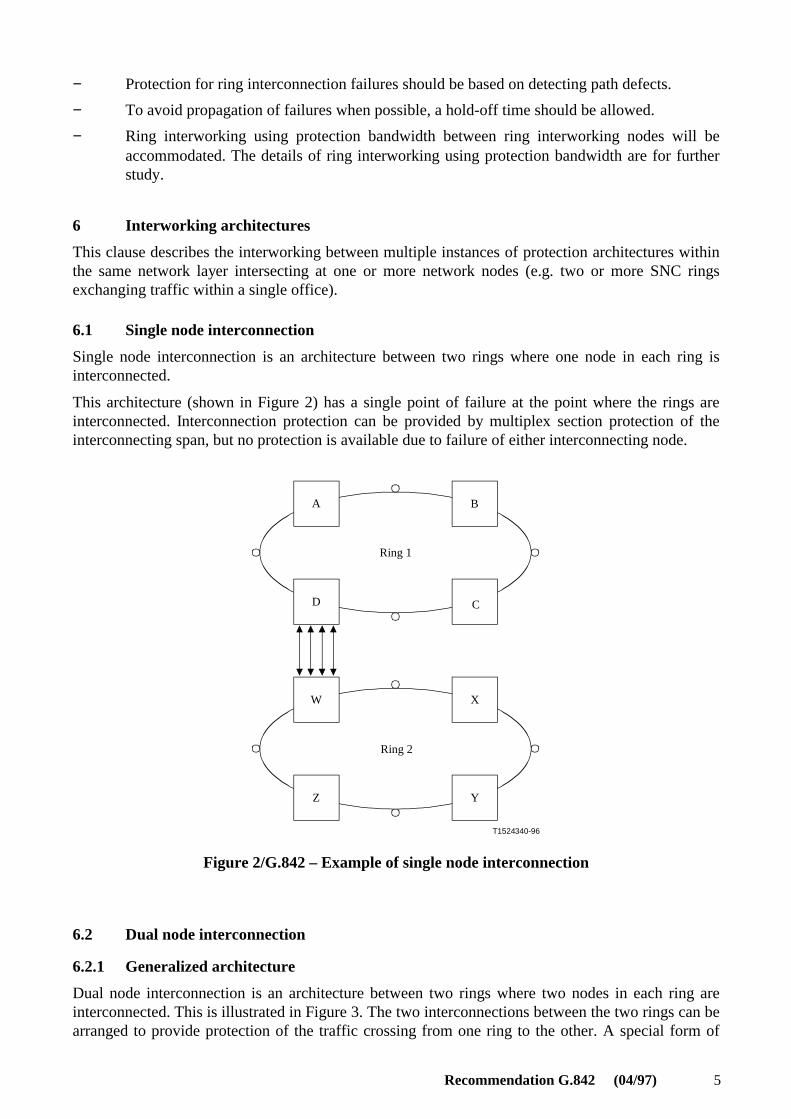
6.1 Single node interconnection
Single node interconnection is an architecture between two rings where one node in each ring isinterconnected.
This architecture (shown in Figure 2) has a single point of failure at the point where the rings areinterconnected. Interconnection protection can be provided by multiplex section protection of theinterconnecting span, but no protection is available due to failure of either interconnecting node.
T1524340-96
A B
D C
XW
Z Y
Ring 1
Ring 2
Figure 2/G.842 – Example of single node interconnection
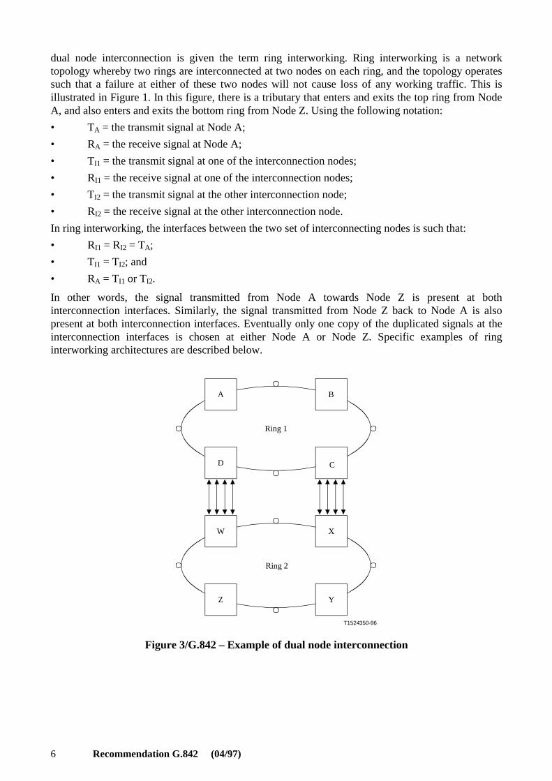
6.2 Dual node interconnection
6.2.1 Generalized architecture
Dual node interconnection is an architecture between two rings where two nodes in each ring areinterconnected. This is illustrated in Figure 3. The two interconnections between the two rings can bearranged to provide protection of the traffic crossing from one ring to the other. A special form of
6 Recommendation G.842 (04/97)
dual node interconnection is given the term ring interworking. Ring interworking is a networktopology whereby two rings are interconnected at two nodes on each ring, and the topology operatessuch that a failure at either of these two nodes will not cause loss of any working traffic. This isillustrated in Figure 1. In this figure, there is a tributary that enters and exits the top ring from NodeA, and also enters and exits the bottom ring from Node Z. Using the following notation:
• TA = the transmit signal at Node A;
• RA = the receive signal at Node A;
• TI1 = the transmit signal at one of the interconnection nodes;
• RI1 = the receive signal at one of the interconnection nodes;
• TI2 = the transmit signal at the other interconnection node;
• RI2 = the receive signal at the other interconnection node.
In ring interworking, the interfaces between the two set of interconnecting nodes is such that:
• RI1 = RI2 = TA;
• TI1 = TI2; and
• RA = TI1 or TI2.
In other words, the signal transmitted from Node A towards Node Z is present at bothinterconnection interfaces. Similarly, the signal transmitted from Node Z back to Node A is alsopresent at both interconnection interfaces. Eventually only one copy of the duplicated signals at theinterconnection interfaces is chosen at either Node A or Node Z. Specific examples of ringinterworking architectures are described below.
T1524350-96
A B
D C
XW
Z Y
Ring 1
Ring 2
Figure 3/G.842 – Example of dual node interconnection
Recommendation G.842 (04/97) 7
6.2.2 Ring interworking with an MS-shared protection ring
6.2.2.1 Architecture
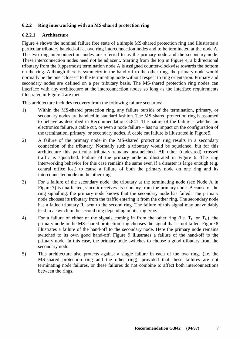
Figure 4 shows the nominal failure free state of a simple MS-shared protection ring and illustrates aparticular tributary handed-off at two ring interconnection nodes and to be terminated at the node A.The two ring interconnection nodes are referred to as the primary node and the secondary node.These interconnection nodes need not be adjacent. Starting from the top in Figure 4, a bidirectionaltributary from the (uppermost) termination node A is assigned counter-clockwise towards the bottomon the ring. Although there is symmetry in the hand-off to the other ring, the primary node wouldnormally be the one "closest" to the terminating node without respect to ring orientation. Primary andsecondary nodes are defined on a per tributary basis. The MS-shared protection ring nodes caninterface with any architecture at the interconnection nodes so long as the interface requirementsillustrated in Figure 4 are met.
This architecture includes recovery from the following failure scenarios:
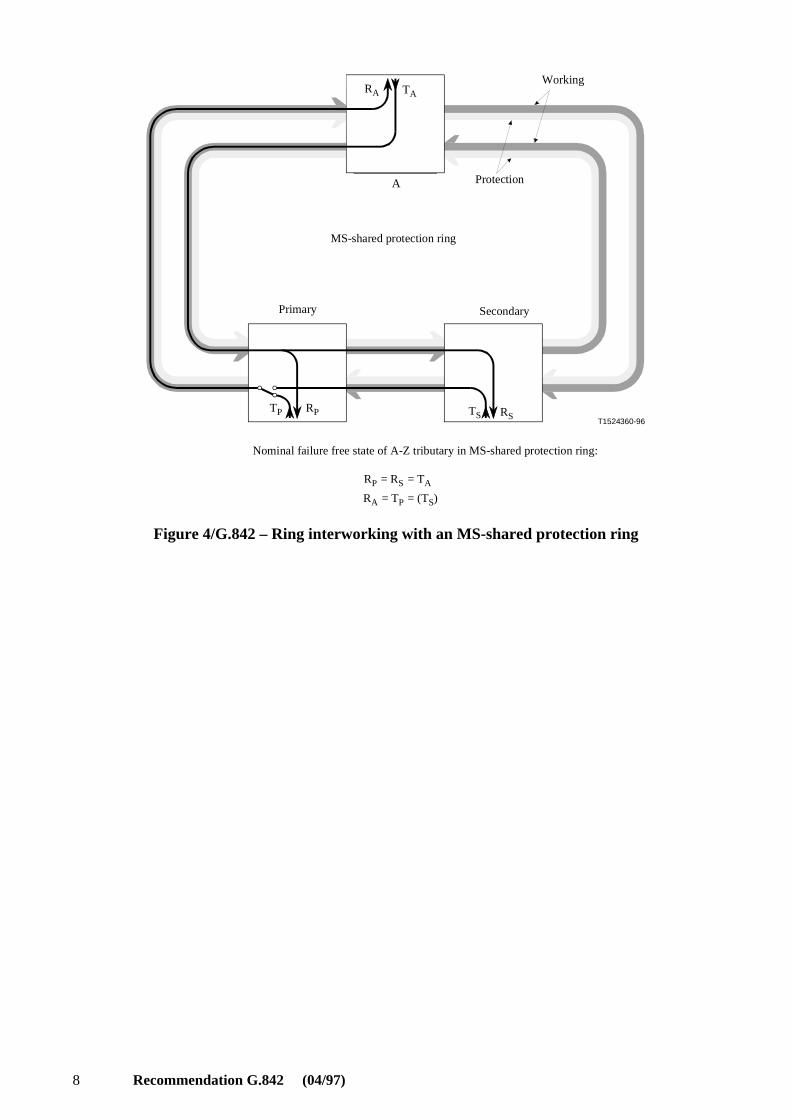
1) Within the MS-shared protection ring, any failure outside of the termination, primary, orsecondary nodes are handled in standard fashion. The MS-shared protection ring is assumedto behave as described in Recommendation G.841. The nature of the failure – whether anelectronics failure, a cable cut, or even a node failure – has no impact on the configuration ofthe termination, primary, or secondary nodes. A cable cut failure is illustrated in Figure 5.
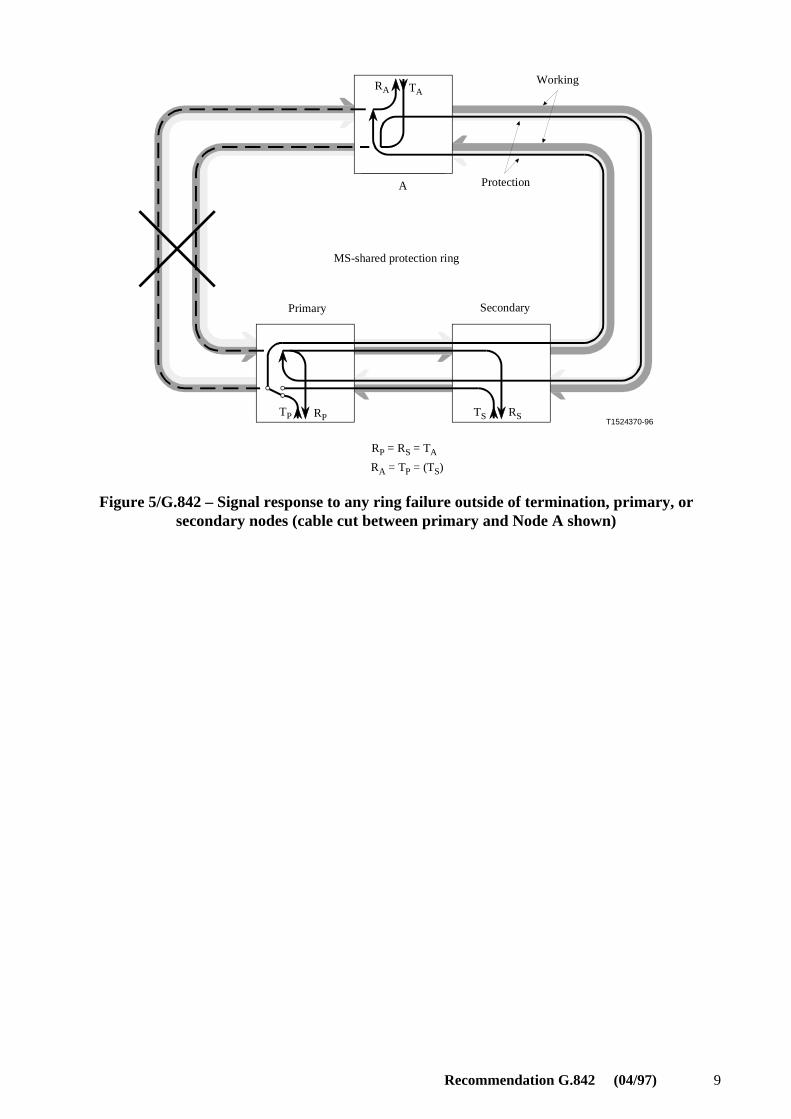
2) A failure of the primary node in the MS-shared protection ring results in a secondaryconnection of the tributary. Normally such a tributary would be squelched, but for thisarchitecture this particular tributary remains unsquelched. All other (undesired) crossedtraffic is squelched. Failure of the primary node is illustrated in Figure 6. The ringinterworking behavior for this case remains the same even if a disaster is large enough (e.g.central office lost) to cause a failure of both the primary node on one ring and itsinterconnected node on the other ring.
3) For a failure of the secondary node, the tributary at the terminating node (see Node A inFigure 7) is unaffected, since it receives its tributary from the primary node. Because of thering signalling, the primary node knows that the secondary node has failed. The primarynode chooses its tributary from the traffic entering it from the other ring. The secondary nodehas a failed tributary RS sent to the second ring. The failure of this signal may unavoidablylead to a switch in the second ring depending on its ring type.
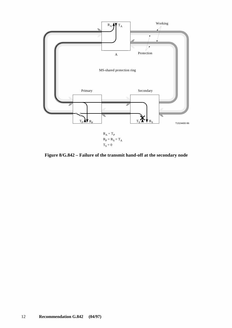
4) For a failure of either of the signals coming in from the other ring (i.e. TI1 or TI2), theprimary node in the MS-shared protection ring chooses the signal that is not failed. Figure 8illustrates a failure of the hand-off to the secondary node. Here the primary node remainsswitched to its own good hand-off. Figure 9 illustrates a failure of the hand-off to theprimary node. In this case, the primary node switches to choose a good tributary from thesecondary node.
5) This architecture also protects against a single failure in each of the two rings (i.e. theMS-shared protection ring and the other ring), provided that these failures are notterminating node failures, or these failures do not combine to affect both interconnectionsbetween the rings.
8 Recommendation G.842 (04/97)
T1524360-96
RA TA
TP RP TS RS
A
RP = RS = TA
RA = TP = (TS)
Working
Protection
MS-shared protection ring
Primary Secondary
Nominal failure free state of A-Z tributary in MS-shared protection ring:
Figure 4/G.842 – Ring interworking with an MS-shared protection ring
Recommendation G.842 (04/97) 9
T1524370-96
RA TA
TP RP TS RS
A
RP = RS = TA
RA = TP = (TS)
Working
Protection
MS-shared protection ring
Primary Secondary
Figure 5/G.842 – Signal response to any ring failure outside of termination, primary, orsecondary nodes (cable cut between primary and Node A shown)
10 Recommendation G.842 (04/97)
T1524380-96
RA TA
TP TS RS
A
RA = TS
RS = TA
RP = TP = 0
RP
Working
Protection
MS-shared protection ring
Primary Secondary
Figure 6/G.842 – Signal response to complete primary node failure
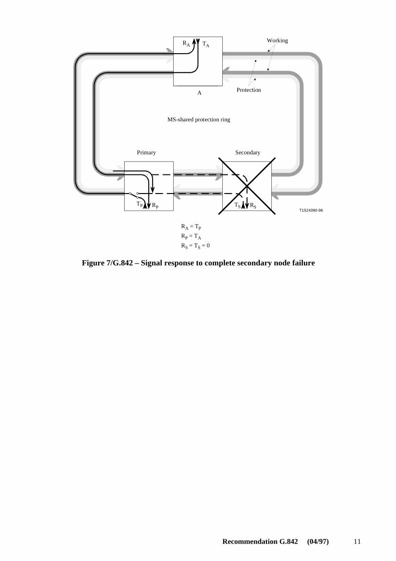
Recommendation G.842 (04/97) 11
T1524390-96
RA = TP
RP = TA
RS = TS = 0
RA TA
TP RP RS
A
TS
Working
Protection
MS-shared protection ring
Primary Secondary
Figure 7/G.842 – Signal response to complete secondary node failure
12 Recommendation G.842 (04/97)
T1524400-96
RA TA
TP RP TS RS
A
RA = TP
RP = RS = TA
TS = 0
Working
Protection
MS-shared protection ring
Primary Secondary
Figure 8/G.842 – Failure of the transmit hand-off at the secondary node

Recommendation G.842 (04/97) 13
T1524410-96
RA TA
TP RPTS RS
A
RA = TP
RP = RS = TA
TS = 0
Working
Protection
MS-shared protection ring
Primary Secondary
Figure 9/G.842 – Failure of the transmit hand-off at the primary node
6.2.2.1.1 Routing with all traffic on working channels
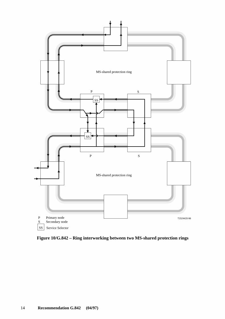
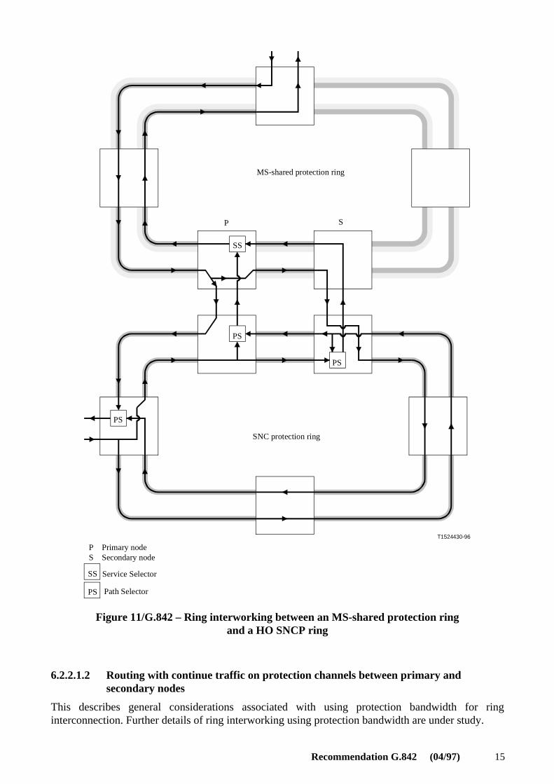
For the unidirectional signal transmitted from the node A, the primary node dual feeds that signalboth towards its own interface and towards the multiplex section to the secondary node. Thisfunction is often referred to as drop-and-continue. In the other direction, the primary node selects, viaa service selector, between the hand-offs to the primary and secondary nodes from the other ring, andtransmits that selection to the upper terminating node. The interconnections are at the STM-1electrical or STM-N optical level. The same channel assignment on the multiplex section usedbetween the secondary and primary nodes is the same as that used between the primary andterminating nodes. Figures 10 and 11 give two ring interworking examples. Interworking of anMS-shared protection ring with a lower order SNCP ring may require further study. With theswitching criteria from 6.2.2.3 and squelching logic from 6.2.2.4, this interconnection architectureprovides protection against the failure of one or both interconnecting nodes (each on different rings,but on the same interconnect), or the connection between the two interconnecting nodes.Furthermore, the interconnection architecture does not require inter-ring signalling.
14 Recommendation G.842 (04/97)
T1524420-96
SS
P S
SS
P S
MS-shared protection ring
P Primary nodeS Secondary node
SS Service Selector
MS-shared protection ring
Figure 10/G.842 – Ring interworking between two MS-shared protection rings
Recommendation G.842 (04/97) 15
T1524430-96
P S
SS
PS
PS
PS
PS
SS
MS-shared protection ring
P Primary nodeS Secondary node
Service Selector
Path Selector
SNC protection ring
Figure 11/G.842 – Ring interworking between an MS-shared protection ringand a HO SNCP ring
6.2.2.1.2 Routing with continue traffic on protection channels between primary andsecondary nodes
This describes general considerations associated with using protection bandwidth for ringinterconnection. Further details of ring interworking using protection bandwidth are under study.
16 Recommendation G.842 (04/97)
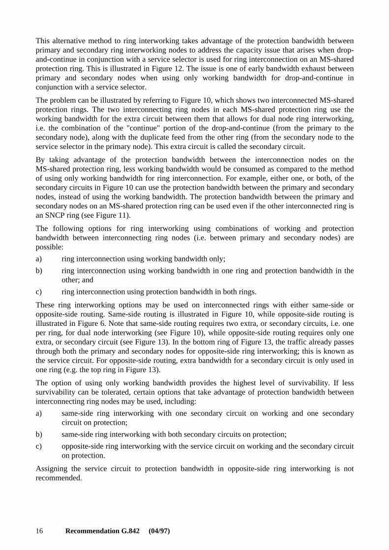
This alternative method to ring interworking takes advantage of the protection bandwidth betweenprimary and secondary ring interworking nodes to address the capacity issue that arises when drop-and-continue in conjunction with a service selector is used for ring interconnection on an MS-sharedprotection ring. This is illustrated in Figure 12. The issue is one of early bandwidth exhaust betweenprimary and secondary nodes when using only working bandwidth for drop-and-continue inconjunction with a service selector.
The problem can be illustrated by referring to Figure 10, which shows two interconnected MS-sharedprotection rings. The two interconnecting ring nodes in each MS-shared protection ring use theworking bandwidth for the extra circuit between them that allows for dual node ring interworking,i.e. the combination of the "continue" portion of the drop-and-continue (from the primary to thesecondary node), along with the duplicate feed from the other ring (from the secondary node to theservice selector in the primary node). This extra circuit is called the secondary circuit.
By taking advantage of the protection bandwidth between the interconnection nodes on theMS-shared protection ring, less working bandwidth would be consumed as compared to the methodof using only working bandwidth for ring interconnection. For example, either one, or both, of thesecondary circuits in Figure 10 can use the protection bandwidth between the primary and secondarynodes, instead of using the working bandwidth. The protection bandwidth between the primary andsecondary nodes on an MS-shared protection ring can be used even if the other interconnected ring isan SNCP ring (see Figure 11).
The following options for ring interworking using combinations of working and protectionbandwidth between interconnecting ring nodes (i.e. between primary and secondary nodes) arepossible:
a) ring interconnection using working bandwidth only;
b) ring interconnection using working bandwidth in one ring and protection bandwidth in theother; and
c) ring interconnection using protection bandwidth in both rings.
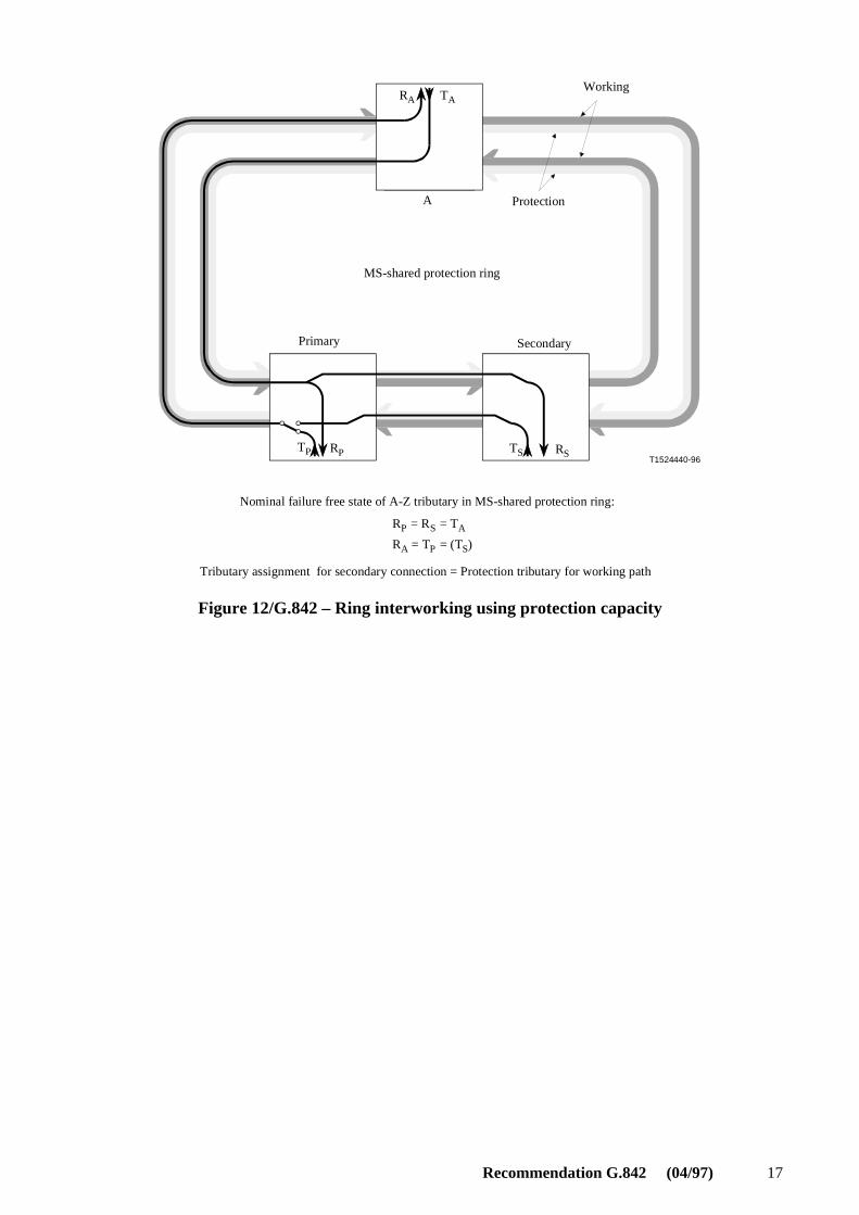
These ring interworking options may be used on interconnected rings with either same-side oropposite-side routing. Same-side routing is illustrated in Figure 10, while opposite-side routing isillustrated in Figure 6. Note that same-side routing requires two extra, or secondary circuits, i.e. oneper ring, for dual node interworking (see Figure 10), while opposite-side routing requires only oneextra, or secondary circuit (see Figure 13). In the bottom ring of Figure 13, the traffic already passesthrough both the primary and secondary nodes for opposite-side ring interworking; this is known asthe service circuit. For opposite-side routing, extra bandwidth for a secondary circuit is only used inone ring (e.g. the top ring in Figure 13).
The option of using only working bandwidth provides the highest level of survivability. If lesssurvivability can be tolerated, certain options that take advantage of protection bandwidth betweeninterconnecting ring nodes may be used, including:
a) same-side ring interworking with one secondary circuit on working and one secondarycircuit on protection;
b) same-side ring interworking with both secondary circuits on protection;
c) opposite-side ring interworking with the service circuit on working and the secondary circuiton protection.
Assigning the service circuit to protection bandwidth in opposite-side ring interworking is notrecommended.
Recommendation G.842 (04/97) 17
T1524440-96
RA TA
A
TP RP TS RS
RP = RS = TA
RA = TP = (TS)
Working
Protection
MS-shared protection ring
Primary Secondary
Tributary assignment for secondary connection = Protection tributary for working path
Nominal failure free state of A-Z tributary in MS-shared protection ring:
Figure 12/G.842 – Ring interworking using protection capacity
18 Recommendation G.842 (04/97)
T1524450-96
A
P1 S1
SS
SS
S2 P2
SS
MS-shared protection ring
Service circuit
MS-shared protection ring
P Primary nodeS Secondary node
Service Selector
Drop and continue
Secondary circuit
Figure 13/G.842 – Ring interworking between two MS-shared protection rings,with opposite-side routing
6.2.2.2 Functional model
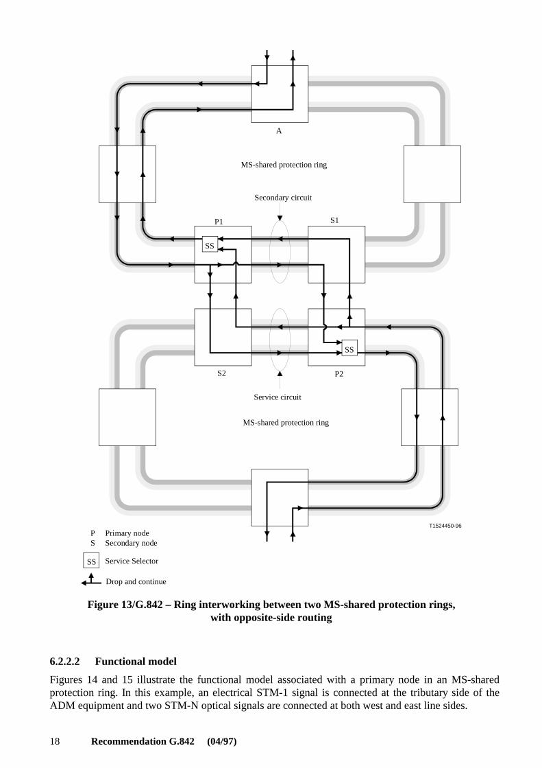
Figures 14 and 15 illustrate the functional model associated with a primary node in an MS-sharedprotection ring. In this example, an electrical STM-1 signal is connected at the tributary side of theADM equipment and two STM-N optical signals are connected at both west and east line sides.

Recommendation G.842 (04/97) 19
A HOVC out of the STM-1 signal has a 1 + 1 SNC protection relation with a HOVC out of the westSTM-N signal; the selected HOVC signal is connected to the east STM-N signal. In the otherdirection the associated HOVC at the east STM-N signal is dual-fed to both the STM-1 and westSTM-N signals.
For the case of SNC/N protection (Figure 15), the HOVC out of the STM-1 is also connected to theinterface with a HPOM function. Similarly, the HOVC out of the west STM-N is connected also to aHPOM function.
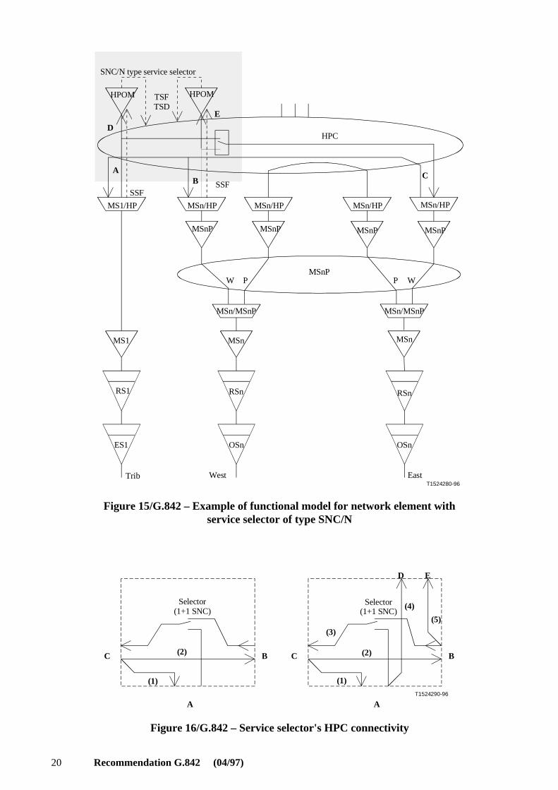
Figure 16 illustrates the matrix connections within the HPC that realise the "service selector". For thecase of SNC/I three matrix connections are required: (1) .. (3). For the case of SNC/N five matrixconnections are required: (1) .. (5).
NOTE – The HPC interfaces A, B, C, D, E in Figure 16 represent the same interfaces in Figures 14 and 15.
T1524270-96
MSn/MSnP
MSn
MSnP
MSn/MSnP
MSn
HPC
W P WP
MS1/HP
MS1
MSn/HP
MSnP MSnP
MSn/HP MSn/HP
MSnP MSnP
MSn/HP
SSFSSF
RS1
ES1
RSn
OSn
RSn
OSn
AB
C
West EastTrib
SNC/I typeservice selector
Figure 14/G.842 – Example of functional model for network elementwith service selector of type SNC/I
20 Recommendation G.842 (04/97)
T1524280-96
MSn/MSnP
MSn
MSnP
MSn/MSnP
MSn
HPC
W P WP
MS1/HP
MS1
MSn/HP
MSnP MSnP
MSn/HP MSn/HP
MSnP MSnP
MSn/HP
SSFSSF
RS1
ES1
RSn
OSn
RSn
OSn
HPOM TSFTSD
HPOM
AB
C
D
E
West EastTrib
SNC/N type service selector
Figure 15/G.842 – Example of functional model for network element withservice selector of type SNC/N
T1524290-96
(1)
(2)
(3)
A
C
(1)
(2)
A
B
D E
(4)
(5)
Selector(1+1 SNC)
B
Selector(1+1 SNC)
C
Figure 16/G.842 – Service selector's HPC connectivity

Recommendation G.842 (04/97) 21
6.2.2.3 Switching criteria and operation
At the primary node, a service selector is used to select the better of two incoming tributaries, i.e. thetributary from the interconnecting line or the tributary from the secondary node. The service selectorstrigger on path layer criteria. The hierarchy of conditions for MS-shared protection ring serviceselection switch initiation is listed in Table 1. The switching hierarchy must select the least impactedsignal under multiple failures occurring at different levels on the same path.
Table 1/G.842 – Hierarchy of conditions for service selector (see Note 3)
Condition Priority (see Note 1)
AIS, LOP, UNEQ defect, TIM (optional), or server signal fail(see Note 2)
1 (hard failure)
Excessive error defect (optional) 2 (hard failure)
Signal degrade 3
NOTE 1 – The highest priority (1) corresponds to the worst impairment, and the lowestpriority (3) corresponds to the least impairment.
NOTE 2 – Server signal fail arises as a result of section defects; e.g. LOS, LOF.
NOTE 3 – For the case of SNC/I, only AIS, LOP, or server signal fail are applicable.
The service selector shall be capable of revertive or non-revertive operation. To have a knownfailure-free state, it may be desirable to have the service selector be revertive. In the case ofconditions of identical severity arriving on both incoming tributaries, the service selector shall selectthe preferred route in the case of revertive operation, or the current (i.e. active or currently selected)route in the case of non-revertive operation. This may be subject to a hold-off time.
In a future revision, when Recommendations G.841, G.783, and this Recommendation are aligned,Table 1 can be replaced by a reference to Recommendations G.841 and G.783.
6.2.2.4 Squelching logic
For the case of the failure of the primary node, the connection of the signal between the terminationA and the secondary node is maintained. This is called a secondary connection.
An MS-shared protection ring providing the sort of ring interworking described here must beprovisionable on a per channel basis to allow a secondary connection or to squelch the traffic in thecase of a node failure as required for the particular application and circuit. The squelching for a ringinterworking circuit is simply based on the failure of either of the endpoints for the interconnectedcircuit, because a switching node should squelch the channel in Figure 4 if and only if node A fails orthe secondary node fails. If the secondary node fails and the primary node is the switching node,observe that the primary squelches bidirectionally with respect to the signal towards the secondarynode, but that the bidirectional connection from the primary node to node A is maintained.
The rules for squelching logic when interworking using protection capacity are for further study.
6.2.3 Ring interworking with an SNCP ring
6.2.3.1 Architecture
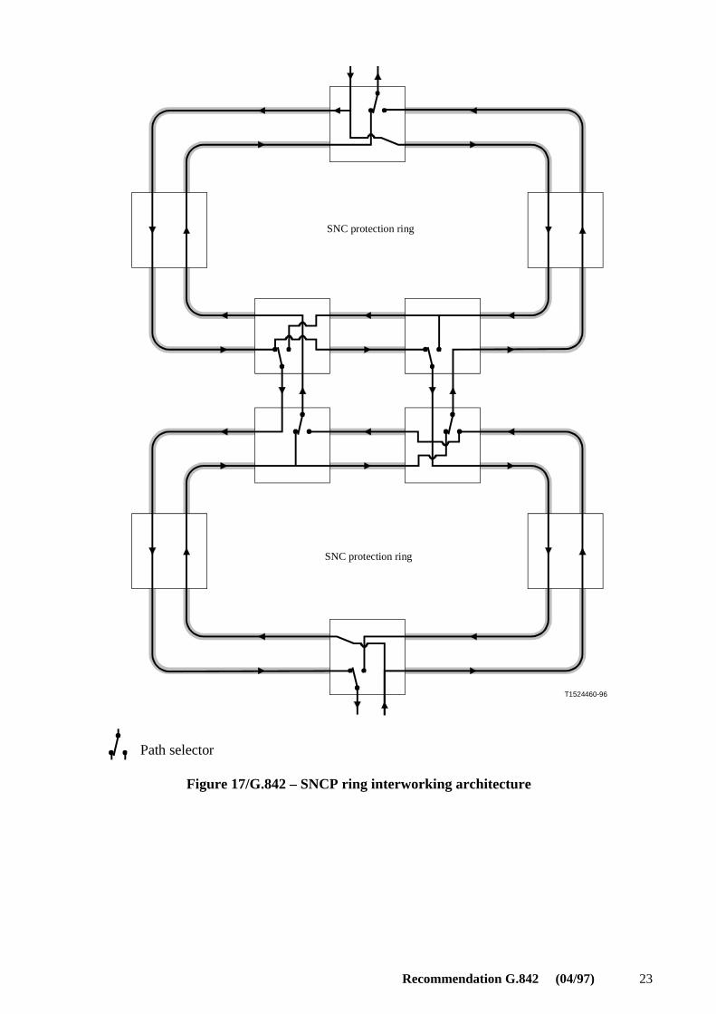
Figure 17 shows the architecture of SNCP ring interworking. For each direction of transmission, thesignal is dual-fed from the source node around both sides of the ring. When each of the dual-fedsignals hits an interconnection node, it is dropped at that node and continued onto the otherinterconnection node using the drop-and-continue feature. Thus, each interconnection node can select

22 Recommendation G.842 (04/97)
from two signals sent on a different way around the ring. The output of the selector in eachinterconnection node is then transmitted to the second ring. Each of the interconnection nodes in thesecond ring takes its respective signal and transmits it towards the sink node, away from the otherinterconnection node. Finally, the sink node makes the selection between the two signals from thetwo directions around the ring.
Due to the symmetry of this scheme, the two interconnection nodes are completely equivalent.
Interworking between higher order SNCP rings and lower order SNCP rings may require furtherstudy.
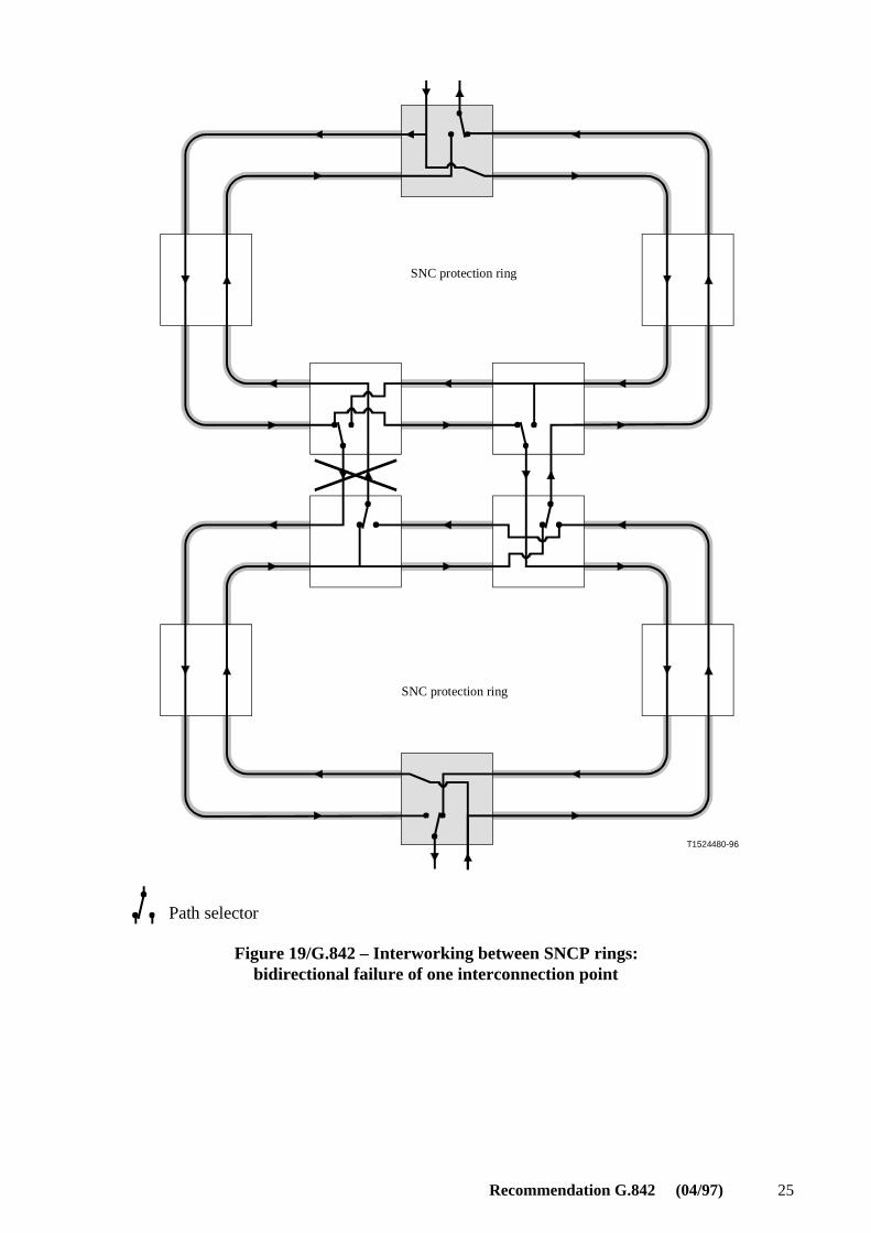
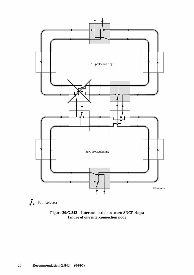
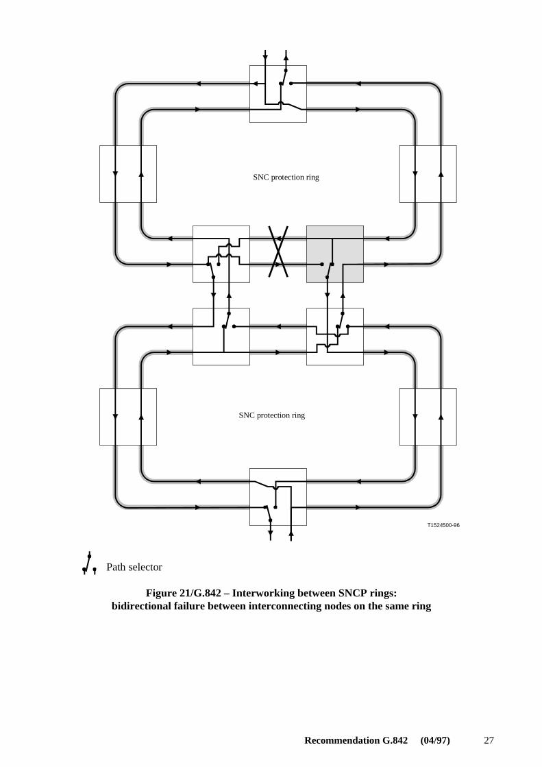
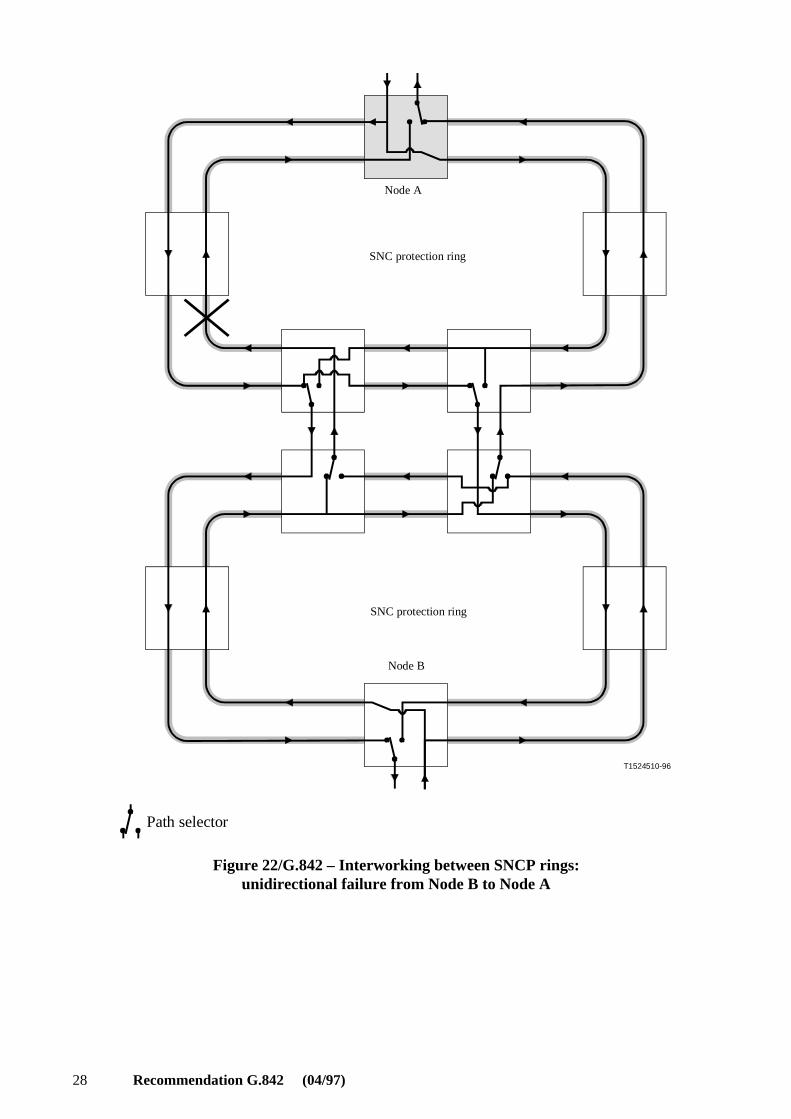
Some examples of reconfiguration in case of failure are shown in Figures 18 through 23:
− Figure 18 shows a bidirectional span failure in one ring;
− Figure 19 shows a bidirectional failure of one interconnection link;
− Figure 20 shows a nodal failure at one interconnection point;
− Figure 21 shows a bidirectional failure between interconnecting nodes on the same ring;
− Figures 22 and 23 show unidirectional failures in each direction assuming unidirectionalworking of SNCP.
In each figure, the nodes where switching should occur to restore the interworking traffic areshadowed. Due to different switching time of network elements, different final configurations arepossible (see clause 8).
Recommendation G.842 (04/97) 23
T1524460-96
SNC protection ring
SNC protection ring
Path selector
Figure 17/G.842 – SNCP ring interworking architecture

24 Recommendation G.842 (04/97)
T1524470-96
SNC protection ring
SNC protection ring
Path selector
Figure 18/G.842 – Interworking between SNCP rings: bidirectional failure in one ring
Recommendation G.842 (04/97) 25
T1524480-96
SNC protection ring
SNC protection ring
Path selector
Figure 19/G.842 – Interworking between SNCP rings:bidirectional failure of one interconnection point
26 Recommendation G.842 (04/97)
T1524490-96
SNC protection ring
SNC protection ring
Path selector
Figure 20/G.842 – Interconnection between SNCP rings:failure of one interconnection node
Recommendation G.842 (04/97) 27
T1524500-96
SNC protection ring
SNC protection ring
Path selector
Figure 21/G.842 – Interworking between SNCP rings:bidirectional failure between interconnecting nodes on the same ring
28 Recommendation G.842 (04/97)
T1524510-96
Node A
SNC protection ring
SNC protection ring
Node B
Path selector
Figure 22/G.842 – Interworking between SNCP rings:unidirectional failure from Node B to Node A

Recommendation G.842 (04/97) 29
T1524520-96
SNC protection ring
Node A
SNC protection ring
Node B
Path selector
Figure 23/G.842 – Interworking between SNCP rings:unidirectional failure from Node A to Node B
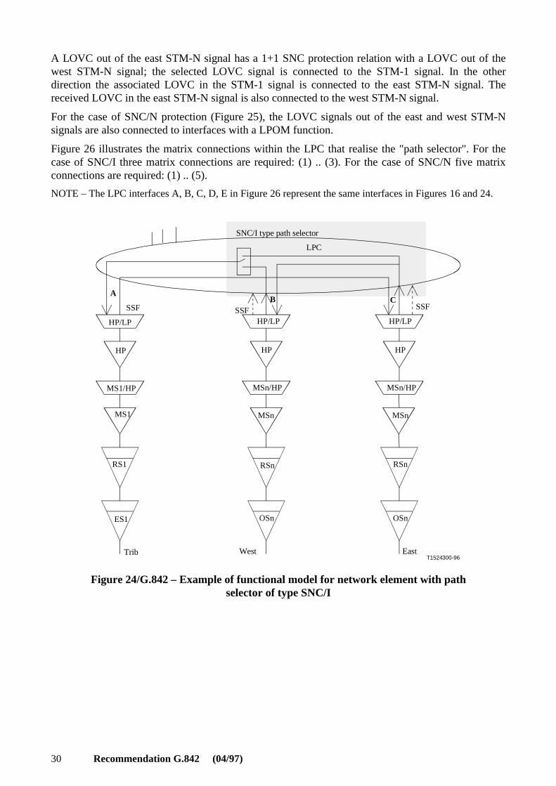
6.2.3.2 Functional model
Figures 24 and 25 illustrate the functional model associated with an interconnecting node in an LOSNC protected ring. In this example, an electrical STM-1 signal is connected at the tributary side ofthe ADM equipment and two STM-N optical signals are connected at both west and east line sides.
30 Recommendation G.842 (04/97)
A LOVC out of the east STM-N signal has a 1+1 SNC protection relation with a LOVC out of thewest STM-N signal; the selected LOVC signal is connected to the STM-1 signal. In the otherdirection the associated LOVC in the STM-1 signal is connected to the east STM-N signal. Thereceived LOVC in the east STM-N signal is also connected to the west STM-N signal.
For the case of SNC/N protection (Figure 25), the LOVC signals out of the east and west STM-Nsignals are also connected to interfaces with a LPOM function.
Figure 26 illustrates the matrix connections within the LPC that realise the "path selector". For thecase of SNC/I three matrix connections are required: (1) .. (3). For the case of SNC/N five matrixconnections are required: (1) .. (5).
NOTE – The LPC interfaces A, B, C, D, E in Figure 26 represent the same interfaces in Figures 16 and 24.
T1524300-96
LPC
AB C
SSF SSF SSF
HP/LP HP/LP HP/LP
HP HP HP
MS1/HP MSn/HP MSn/HP
MSnMS1 MSn
RSnRS1 RSn
ES1 OSn OSn
West EastTrib
SNC/I type path selector
Figure 24/G.842 – Example of functional model for network element with pathselector of type SNC/I

Recommendation G.842 (04/97) 31
T1524310-96
MSn MSn
LPC
MS1/HP
MS1
MSn/HP
SSF
RS1
ES1
RSn
OSn
RSn
OSn
LPOM TSFTSD
LPOM
A
BC
DE
MSn/HP
HP
HP/LP
HP
HP/LP
HP
HP/LP
TSFTSD
West EastTrib
SNC/N type path selector
Figure 25/G.842 – Example of functional model for network elementwith path selector of type SNC/N
T1524320-96
C B
A
(1)
(2)
(3)
C B
A
(2)
(3)
E D
(4)(5)selector(1+1 SNC)
selector
(1) (1+1 SNC)
Figure 26/G.842 – Path selector's LPC connectivity
32 Recommendation G.842 (04/97)
6.2.3.3 Switching criteria and operation
The switching criteria for the path selector in SNCP protection interworking is the same as for theservice selector in MS-shared protection ring interworking. See 6.2.2.3.
6.2.4 Multiple rings
(One issue that may be described here is the mixing of traffic that is dual-node coupled with trafficthat is only single-node coupled. Another is the interworking of rings that hand off LO VC trafficonto rings that incorporate this traffic into either HO SNC architectures, or MS-shared protectionrings).
7 Interworking among network layers
[This clause describes the interworking between protection applications within different layers of thenetwork (e.g. between MS-shared protection rings and VC trail protection).]
8 Switch contention
It is recognized that problems may occur due to contention between protection switch operation ininterworking protection architectures. The contention may be inter-layer or intra-layer. Thiscontention may result in multiple hits being introduced and may leave the switches in anindeterminate state. The outcome of the switching actions which are in contention is dependent uponthe relative speed of operation of the protection switches and on the relative transmission delay onalternative routes. These problems may be solved by the use of hold-off times or by defining defaultpositions for the switches (which would require revertive operation) in the absence of failures.
The detailed definition of these problems and the exploration of possible solutions are left for furtherstudy.
ITU-T RECOMMENDATIONS SERIES
Series A Organization of the work of the ITU-T
Series B Means of expression: definitions, symbols, classification
Series C General telecommunication statistics
Series D General tariff principles
Series E Overall network operation, telephone service, service operation and human factors
Series F Non-telephone telecommunication services
Series G Transmission systems and media, digital systems and networks
Series H Audiovisual and multimedia systems
Series I Integrated services digital network
Series J Transmission of television, sound programme and other multimedia signals
Series K Protection against interference
Series L Construction, installation and protection of cables and other elements of outside plant
Series M TMN and network maintenance: international transmission systems, telephone circuits,telegraphy, facsimile and leased circuits
Series N Maintenance: international sound programme and television transmission circuits
Series O Specifications of measuring equipment
Series P Telephone transmission quality, telephone installations, local line networks
Series Q Switching and signalling
Series R Telegraph transmission
Series S Telegraph services terminal equipment
Series T Terminals for telematic services
Series U Telegraph switching
Series V Data communication over the telephone network
Series X Data networks and open system communication
Series Z Programming languages