t rec-g.825-200003-i!!pdf-e
TRANSCRIPT

INTERNATIONAL TELECOMMUNICATION UNION
ITU-T G.825TELECOMMUNICATIONSTANDARDIZATION SECTOR OF ITU
(03/2000)
SERIES G: TRANSMISSION SYSTEMS AND MEDIA, DIGITAL SYSTEMS AND NETWORKS Digital networks � Quality and availability targets
The control of jitter and wander within digital networks which are based on the synchronous digital hierarchy (SDH)
ITU-T Recommendation G.825 (Formerly CCITT Recommendation)
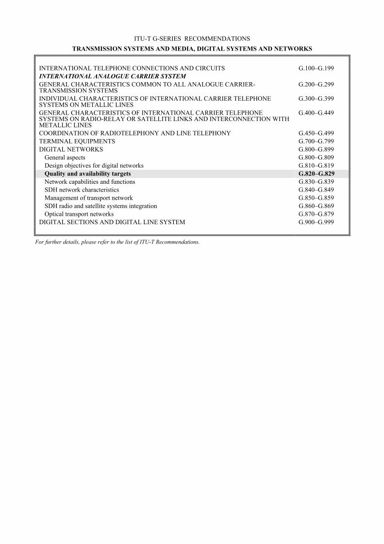
ITU-T G-SERIES RECOMMENDATIONS TRANSMISSION SYSTEMS AND MEDIA, DIGITAL SYSTEMS AND NETWORKS
INTERNATIONAL TELEPHONE CONNECTIONS AND CIRCUITS G.100�G.199 INTERNATIONAL ANALOGUE CARRIER SYSTEM GENERAL CHARACTERISTICS COMMON TO ALL ANALOGUE CARRIER-TRANSMISSION SYSTEMS
G.200�G.299
INDIVIDUAL CHARACTERISTICS OF INTERNATIONAL CARRIER TELEPHONE SYSTEMS ON METALLIC LINES
G.300�G.399
GENERAL CHARACTERISTICS OF INTERNATIONAL CARRIER TELEPHONE SYSTEMS ON RADIO-RELAY OR SATELLITE LINKS AND INTERCONNECTION WITH METALLIC LINES
G.400�G.449
COORDINATION OF RADIOTELEPHONY AND LINE TELEPHONY G.450�G.499 TERMINAL EQUIPMENTS G.700�G.799 DIGITAL NETWORKS G.800�G.899
General aspects G.800�G.809 Design objectives for digital networks G.810�G.819 Quality and availability targets G.820�G.829 Network capabilities and functions G.830�G.839 SDH network characteristics G.840�G.849 Management of transport network G.850�G.859 SDH radio and satellite systems integration G.860�G.869 Optical transport networks G.870�G.879
DIGITAL SECTIONS AND DIGITAL LINE SYSTEM G.900�G.999
For further details, please refer to the list of ITU-T Recommendations.

ITU-T G.825 (03/2000) i
ITU-T Recommendation G.825
The control of jitter and wander within digital networks which are based on the synchronous digital hierarchy (SDH)
Summary This ITU-T Recommendation specifies the maximum network limits of jitter and wander that shall not be exceeded and the minimum equipment tolerance to jitter and wander that shall be provided at any relevant transport or synchronization interfaces which are based on the Synchronous Digital Hierarchy (SDH).
The requirements for the jitter and wander characteristics that are specified in this ITU-T Recommendation must be adhered to in order to ensure interoperability of equipment produced by different manufacturers and a satisfactory network performance.
Source ITU-T Recommendation G.825 was revised by ITU-T Study Group 13 (1997-2000) and approved under the WTSC Resolution 1 procedure on 10 March 2000.
Keywords Clocks, Input Jitter Tolerance, Input Wander Tolerance, Network Limits, Output Jitter, Output Wander, Synchronization, Timing.

ii ITU-T G.825 (03/2000)
FOREWORD
The International Telecommunication Union (ITU) is the United Nations specialized agency in the field of telecommunications. The ITU Telecommunication Standardization Sector (ITU-T) is a permanent organ of ITU. ITU-T is responsible for studying technical, operating and tariff questions and issuing Recommendations on them with a view to standardizing telecommunications on a worldwide basis.
The World Telecommunication Standardization Conference (WTSC), which meets every four years, establishes the topics for study by the ITU-T study groups which, in turn, produce Recommendations on these topics.
The approval of ITU-T Recommendations is covered by the procedure laid down in WTSC Resolution 1.
In some areas of information technology which fall within ITU-T�s purview, the necessary standards are prepared on a collaborative basis with ISO and IEC.
NOTE
In this Recommendation, the expression "Administration" is used for conciseness to indicate both a telecommunication administration and a recognized operating agency.
INTELLECTUAL PROPERTY RIGHTS
ITU draws attention to the possibility that the practice or implementation of this Recommendation may involve the use of a claimed Intellectual Property Right. ITU takes no position concerning the evidence, validity or applicability of claimed Intellectual Property Rights, whether asserted by ITU members or others outside of the Recommendation development process.
As of the date of approval of this Recommendation, ITU had not received notice of intellectual property, protected by patents, which may be required to implement this Recommendation. However, implementors are cautioned that this may not represent the latest information and are therefore strongly urged to consult the TSB patent database.
� ITU 2001
All rights reserved. No part of this publication may be reproduced or utilized in any form or by any means, electronic or mechanical, including photocopying and microfilm, without permission in writing from the ITU.

ITU-T G.825 (03/2000) iii
CONTENTS Page
1 Scope........................................................................................................................... 1
2 References................................................................................................................... 1
3 Definitions .................................................................................................................. 2
4 Abbreviations.............................................................................................................. 2
5 Network limits for the maximum output jitter and wander at any hierarchical interface ...................................................................................................................... 3
5.1 Network limits for jitter .............................................................................................. 3
5.2 Network limits for wander .......................................................................................... 4
6 The specification of individual digital equipment ...................................................... 4
6.1 Jitter and wander tolerance for STM-N input ports.................................................... 4 6.1.1 STM-N input wander tolerance ..................................................................... 6 6.1.2 STM-N input jitter tolerance ......................................................................... 6
6.2 Jitter and wander generation ....................................................................................... 10
6.3 Jitter and wander transfer............................................................................................ 10
Appendix I − Relationship between network interface jitter requirements and input jitter tolerance...................................................................................................................... 11
I.1 Network interface jitter requirements ......................................................................... 11
I.2 Input jitter tolerance of network equipment ............................................................... 12
Appendix II − Measurement methodology for output wander of synchronous interfaces ...... 14
Appendix III − SDH Line systems and Interworking implications ......................................... 14

iv ITU-T G.825 (03/2000)
Introduction and background In a digital network, jitter and wander accumulate on transmission paths according to the jitter and wander generation and transfer characteristics of each equipment interconnected. This equipment may be different types of multiplexers/demultiplexers, cross-connects, clocks and line systems, for example.
An excessive amount of jitter and wander can adversely affect both digital (e.g. by generation of bit errors, slips and other abnormalities) and analogue signals (e.g. by unwanted phase modulation of the transmitted signal). The consequences of such impairment will, in general, depend on the particular service that is being carried and the terminating or adaptation equipment involved.
It is therefore necessary to set limits on the maximum magnitude of jitter and wander, and the corresponding minimum jitter and wander tolerance at network interfaces, in order to guarantee a proper quality of the transmitted signals and a proper design of the equipment.
These network limits are independent from the particular service that is being carried.

ITU-T G.825 (03/2000) 1
ITU-T Recommendation G.825
The control of jitter and wander within digital networks which are based on the synchronous digital hierarchy (SDH)
1 Scope The scope of this ITU-T Recommendation is to define the parameters and the relevant values that are able to control satisfactorily the amount of jitter and wander present at the SDH network-network interfaces (NNI).
SDH network interfaces, to which this ITU-T Recommendation is applicable, are defined in terms of bit rates and frame structures in ITU-T Recommendation G.707; their electrical characteristics are described in ITU-T Recommendation G.703 and the optical characteristics in ITU-T Recommendations G.957 and G.691.
Additional information regarding the architecture of SDH networks is found in ITU-T Recommendation G.803.
Jitter and wander requirements for PDH and synchronization networks are specified in ITU-T Recommendation G.823, for networks based on the first level bit rate of 2048 kbit/s, and in ITU-T Recommendation G.824 for networks based on the first-level bit rate of 1544 kbit/s.
The jitter and wander control philosophy is based on the need: � to recommend a maximum network limit that should not be exceeded at any relevant
interface; � to recommend a consistent framework for the specification of individual digital equipment
(i.e. jitter and wander transfer, tolerance and generation requirements); � to provide sufficient information and guidelines for organizations to measure and study jitter
and wander accumulation in any network configuration.
2 References The following ITU-T Recommendations and other references contain provisions which, through reference in this text, constitute provisions of this Recommendation. At the time of publication, the editions indicated were valid. All Recommendations and other references are subject to revision; all users of this Recommendation are therefore encouraged to investigate the possibility of applying the most recent edition of the Recommendations and other references listed below. A list of the currently valid ITU-T Recommendations is regularly published.
� ITU-T Recommendation G.691 (draft), Optical interfaces for single-channel STM-64, STM-256 and other SDH systems with optical amplifiers.
� ITU-T Recommendation G.703 (1998), Physical/electrical characteristics of hierarchical digital interfaces.
� ITU-T Recommendation G.707 (1996), Network Node interface for the Synchronous Digital Hierarchy (SDH).
� ITU-T Recommendation G.783 (1997), Characteristics of synchronous digital hierarchy (SDH) equipment functional blocks.
� ITU-T Recommendation G.803 (2000), Architecture of transport networks based on the synchronous digital hierarchy (SDH).

2 ITU-T G.825 (03/2000)
� ITU-T Recommendation G.810 (1996), Definitions and terminology for synchronization networks.
� ITU-T Recommendation G.811 (1997), Timing characteristics of primary reference clocks.
� ITU-T Recommendation G.812 (1998), Timing requirements of slave clocks suitable for use as node clocks in synchronization networks.
� ITU-T Recommendation G.813 (1996), Timing characteristics of SDH equipment slave clocks (SEC).
� ITU-T Recommendation G.823 (2000), The control of jitter and wander within digital networks which are based on the 2048 kbit/s hierarchy.
� ITU-T Recommendation G.824 (2000), The control of jitter and wander within digital networks which are based on the 1544 kbit/s hierarchy.
� ITU-T Recommendation G.832 (1998), Transport of SDH elements on PDH networks − Frame and multiplexing structures.
� ITU-T Recommendation G.957 (1999), Optical interfaces for equipments and systems relating to the synchronous digital hierarchy.
� ITU-T Recommendation O.171 (1997), Timing jitter and wander measuring equipment for digital systems which are based on the Plesiochronous Digital Hierarchy (PDH).
� ITU-T Recommendation O.172 (1999), Jitter and wander measuring equipment for digital systems which are based on the Synchronous Digital Hierarchy (SDH).
3 Definitions This ITU-T Recommendation defines the following terms. Additional definitions relating to synchronization networks are provided in ITU-T Recommendation G.810.
3.1 synchronous interface: These interfaces provide an output signal with frequency that is normally traceable to a PRC.
3.2 asynchronous interface: These interfaces provide an output signal with frequency that is not traceable to a PRC and that meets the frequency offset requirements given in ITU-T Recommendation G.703.
3.3 synchronization interface: These interfaces are synchronous and network wander limits are specified using Maximum Time Interval Error (MTIE) and Time Deviation (TDEV) parameters with values given in this ITU-T Recommendation.
4 Abbreviations This ITU-T Recommendation uses the following abbreviations. Additional abbreviations will be added.
CMI Code Mark Inversion
ITU-T International Telecommunication Union � Telecommunication Standardization Sector
MRTIE Maximum Relative Time Interval Error
MS-AIS Multiplex Section Alarm Indication Signal
MTIE Maximum Time Interval Error
NE Network Element
NNI Network Node Interface

ITU-T G.825 (03/2000) 3
pk-pk Peak-to-Peak
RTIE Relative Time Interval Error
SDH Synchronous Digital Hierarchy
TDEV Time Deviation
TIE Time Interval Error
UI Unit Interval
UNI User Network Interface
5 Network limits for the maximum output jitter and wander at any hierarchical interface
5.1 Network limits for jitter The limits given in Table 1 represent the maximum permissible levels of jitter at interfaces within a digital network. Jitter as measured over a 60 second interval shall not exceed the limits given in Table 1, when using the specified measurement filters. The limits shall be met for all operating conditions and regardless of the amount of equipment preceding the interface. In general, these network limits are compatible with the minimum tolerance to jitter that all equipment input ports are required to provide. Guidelines for the derivation of the parameters values of Table 1 are given in Appendix I.
There is a close relationship between network limits and input tolerance such that the jitter measurement filter cut-off frequencies used in Table 1 have the same values as the jitter tolerance mask corner frequencies used in 6.1. Appendix I provides further information about this relationship.
The high-pass measurement filters of Table 1 have a first-order characteristic and a roll-off of 20 dB/decade. The low-pass measurement filters have a maximally-flat, Butterworth characteristic and a roll-off of −60 dB/decade.
ITU-T Recommendation O.172 contains a functional description of equipment appropriate for measurement of jitter in SDH systems. Further specifications for the frequency response of the jitter measurement function such as measurement filter accuracy and additional allowed filter poles are also given in ITU-T Recommendation O.172.
Table 1/G.825 −−−− Maximum permissible jitter at network interfaces
Interface Measurement bandwidth, −−−−3 dB frequencies (Hz)
Peak-to-peak amplitude (UIpp)
500 to 1.3 M 1.5 STM-1e (Notes 1, 2) 65 k to 1.3 M 0.075
500 to 1.3 M 1.5 STM-1 (Note 4) 65 k to 1.3 M 0.15
1 k to 5 M 1.5 STM-4 (Note 4) 250 k to 5 M 0.15
5 k to 20 M 1.5 STM-16 (Note 4) 1 M to 20 M 0.15

4 ITU-T G.825 (03/2000)
Table 1/G.825 −−−− Maximum permissible jitter at network interfaces (concluded)
Interface Measurement bandwidth, −−−−3 dB frequencies (Hz)
Peak-to-peak amplitude (UIpp)
20 k to 80 M 1.5 STM-64 (Note 4) 4 M to 80 M 0.15 (Note 3)
NOTE 1 − Electrical format CMI-encoded, according to G.703. NOTE 2 − For networks deployed with G.813 Option II clocks or G.812 Type II, III or IV clocks, STM-1 requirements apply to STM-1e. NOTE 3 − The effect of dispersion and non-linearities on the eye opening and on the choice of this value is for further study. NOTE 4 − STM-1 1 UI = 6.43 ns STM-4 1 UI = 1.61 ns STM-16 1 UI = 0.402 ns STM-64 1 UI = 0.100 ns
5.2 Network limits for wander STM-N interfaces are defined as synchronization interfaces. Network limits for wander at synchronization interfaces are specified in ITU-T Recommendation G.823 for networks based on the 2048 kbit/s hierarchy, and in ITU-T Recommendation G.824 for networks based on the 1544 kbit/s hierarchy.
6 The specification of individual digital equipment To help ensure that the interconnection of digital equipment does not result in accumulated jitter that exceeds network limits, the jitter transfer and jitter generation characteristics of individual equipment are defined. Also to help ensure equipment can operate properly, given the specified network limits, jitter tolerance characteristics are defined.
6.1 Jitter and wander tolerance for STM-N input ports This subclause specifies the jitter and wander tolerance for SDH input ports. Jitter and Wander tolerance for PDH input ports to SDH equipment are specified in ITU-T Recommendations G.823 and G.824.
In order to ensure that, in general, any equipment can be connected to any appropriate interface within a network, it is necessary to arrange that the input ports of all equipment are capable of accommodating levels of jitter and wander up to at least the minimum limits defined in 6.1.1 and 6.1.2.
The jitter and wander tolerance of an SDH interface indicates the minimum level of phase noise that the input port shall accommodate whilst: � not causing any alarms; � not causing any slips; and � not causing any bit errors; except for optical STM-N interfaces at jitter frequencies above fp
(fp is 6.5 kHz for STM-1, 25 kHz for STM-4, 100 kHz for STM-16 and 400 kHz for STM-64), where an equivalent 1 dB optical power penalty shall not be exceeded.

ITU-T G.825 (03/2000) 5
All digital input ports of equipment shall be able to tolerate a digital signal that has: a) electrical characteristics in accordance with the requirements of ITU-T Recommendation
G.703, or the optical characteristics of ITU-T Recommendations G.957 and G.691; b) a frequency offset (relative to the nominal value) within the range defined in Table 2; c) a sinusoidal phase deviation having an amplitude-frequency relationship, defined in the
following subclauses, which indicates the appropriate limits for the different interfaces.
In principle, these requirements shall be met regardless of the information content of the digital signal. However, for test purposes, the content of the signal with jitter and wander modulation should be a structured test sequence as defined in Annex A/O.172.
When specifying or assessing interface tolerance, two equipment operating conditions can be distinguished: � asynchronous operation, where the receiving equipment is not being timed from a source
that is synchronous with the interface under consideration. In this case, it is the equipment capability to accommodate phase variation on the incoming signal (in terms of clock recovery circuitry and synchronizer/desynchronizer buffers) that is of interest.
� synchronous operation, where the receiving equipment is being timed from a source that is synchronous with the interface under consideration. In this case, slip buffer dimension and operation is also of interest.
Unless otherwise stated, the tolerance specifications in 6.1.1 and 6.1.2 apply to both asynchronous and synchronous operating conditions.
The jitter and wander limit above 10 Hz reflects the maximum permissible jitter magnitude in a digital network. However, the limit below 10 Hz does not aim to represent the maximum permissible wander that might occur in practice. Below 10 Hz the limits are derived such that where necessary, the provision of this level of buffer storage at the input of equipment facilitates the accommodation of wander generated in a large proportion of real connections.
For convenience of testing, the required tolerance is defined in terms of the peak-to-peak amplitude and frequency of sinusoidal jitter which modulates a digital test pattern. It is important to recognize that this test condition is not, in itself, intended to be representative of the type of jitter found in practice in a network.
Guidance on the measurement set-up for input jitter and wander tolerance is provided in Appendix III/G.823. Instrumentation in accordance with ITU-T Recommendation O.172 is appropriate for generation of jitter and wander in SDH systems.
Table 2/G.825 −−−− Maximum frequency offset at STM-N interfaces
Maximum frequency offset (±ppm) Example application
4.6 SDH NEs deployed with G.813 Option I clocks
20 MS-AIS in SDH regenerator sections and NEs deployed with G.813 Option II clocks
Requirements for regenerators are provided in ITU-T Recommendation G.783. Appendix III provides additional information.

6 ITU-T G.825 (03/2000)
6.1.1 STM-N input wander tolerance STM-N interfaces used as synchronization interfaces shall meet wander tolerance specifications in ITU-T Recommendations G.812 and G.813. ITU-T Recommendations G.812 and G.813 contain requirements for two network types. For equipment deployed in networks based on the 1544 kbit/s hierarchy, wander tolerance requirements are specified in Option II of ITU-T Recommendation G.813 and for clock types II, III and IV contained in ITU-T Recommendation G.812. For SDH equipment deployed in networks based on the 2048 kbit/s hierarchy, wander tolerance requirements are specified in Option I of ITU-T Recommendation G.813 and for clock types I, V and VI in ITU-T Recommendation G.812.
NOTE − Traffic interfaces are also required to tolerate frequency offsets of at least 20 ppm for the purposes of detection of MS-AIS.
6.1.2 STM-N input jitter tolerance Specific requirements for jitter tolerance for individual STM-N rates are given in the following subclauses. These requirements specify the minimum levels of jitter that must be accommodated at an STM-N interface. Guidance on test sequences suitable for SDH systems is provided in ITU-T Recommendation O.172.
As noted in 6.1.1, SDH equipment can be deployed in different networks. Although the basic jitter tolerance requirements are the same for both networks, the low frequency region of the jitter tolerance requirement will differ to be compatible with the specific network wander requirements that are specified in ITU-T Recommendations G.824 and G.825. These differences are noted in the requirements below.
6.1.2.1 STM 1/1e jitter tolerance The level of jitter that must be accommodated by STM-1 and STM-1e SDH interfaces is specified in Tables 3 and 4 respectively, and are illustrated in Figures 1 and 2. Specifications are given for both optical (STM-1) and electrical (STM-1e) interfaces. Equipment deployed in existing networks may have jitter generation for STM-1e based on STM-1 requirements contained in ITU-T Recommendation G.813. Inter-working between older equipment and equipment meeting the STM-1e requirements in Table 4 is for further study. For networks based on the 1544 kbit/s hierarchy, STM-1e interfaces shall be required to meet the more stringent STM-1 jitter tolerance requirement.
Table 3/G.825 −−−− STM-1 input jitter tolerance limit
Frequency f (Hz)
Requirement (Peak-Peak)
2048 kbit/s networks 1544 kbit/s networks
− 10 < f ≤ 68.7 10.9 UI
10 < f ≤ 19.3 − 38.9 UI (0.25 µs)
19.3 < f ≤ 68.7 − 750 f −1 UI
68.7 < f ≤ 500 750 f −1 UI 500 < f ≤ 6.5 k 1.5 UI
6.5 k < f ≤ 65 k 9.8 × 10³ f −1 UI 65 k < f ≤ 1.3 M 0.15 UI

ITU-T G.825 (03/2000) 7
Table 4/G.825 −−−− STM-1e input jitter tolerance limit
Frequency f (Hz)
Requirement (Peak-Peak)
10 < f ≤ 19.3 38.9 UI (0.25 µs)
19.3 < f ≤ 500 750f −1 UI
500 < f ≤ 3.3 k (Note 2) 1.5 UI
3.3 k < f ≤ 65 k 4.9 × 10³ f −1 UI 65 k < f ≤ 1.3 M 0.075 UI
NOTE 1 − STM-1e interface is CMI-encoded, according to ITU-T Recommendation G.703. NOTE 2 − When STM-1e interfaces are deployed in networks based on the 1544 kbit/s hierarchy they must meet the requirements for STM-1 in Table 3.
T1316810-99Frequency (Hz)
Pk-P
k Ph
ase
Am
plitu
de (U
I)
(Note)
NOTE � The dashed curve is the requirement for 1544 kbit/s networks for frequencies less than 68.7 Hz.
1.0E+00
1.0E+01
1.0E+02
1.0E+01 1.0E+03 1.0E+051.0E�01
1.0E+00 1.0E+02 1.0E+04 1.0E+06 1.0E+07
Figure 1/G.825 −−−− STM-1 jitter tolerance
T1316820-99
100
10
1
1.0E+01 1.0E+03 1.0E+051.0E+02 1.0E+04Frequency (Hz)
1.0E+06 1.0E+07
0.1
0.01
Uni
t Int
erva
ls (U
Ipp)
Figure 2/G.825 −−−− STM-1e jitter tolerance requirement (applies to 2048 kbit/s networks only)

8 ITU-T G.825 (03/2000)
6.1.2.2 STM-4 jitter tolerance The level of jitter that must be accommodated by STM-4 SDH interfaces is specified in Table 5 and illustrated in Figure 3.
Table 5/G.825 −−−− STM-4 input jitter tolerance limit
Frequency f (Hz)
Requirement (Peak-Peak)
2048 kbit/s networks 1544 kbit/s networks
− 10 < f ≤ 18.5 277.5 f −1 UI
− 18.5 < f ≤ 100 15 UI
9.65 < f ≤ 100 − 1500 f −1 UI
100 < f ≤ 1000 1500 f −1 UI 1 k < f ≤ 25 k 1.5 UI
25 k < f ≤ 250 k 3.8 × 10⁴ f −1 UI 250 k < f ≤ 5 M 0.15 UI
T1316830-99
1.0E+00
1.0E+01
1.0E+02
1.0E+01 1.0E+03 1.0E+051.0E�01
1.0E+00 1.0E+02 1.0E+04Frequency (Hz)
1.0E+06 1.0E+07
Pk-P
k Ph
ase
Am
plitu
de (U
I)
1.0E+03
(Note)
NOTE � The dashed curve is the requirement for 1544 kbit/s networks for frequencies less than 100 Hz.
Figure 3/G.825 −−−− STM-4 jitter tolerance
6.1.2.3 STM-16 jitter tolerance The level of jitter that must be accommodated by STM-16 SDH interfaces is specified in Table 6 and illustrated in Figure 4.

ITU-T G.825 (03/2000) 9
Table 6/G.825 −−−− STM-16 input jitter tolerance limit
Frequency f (Hz)
Requirement (Peak-Peak)
2048 kbit/s networks 1544 kbit/s networks
− 10 < f ≤ 70.9 1063.5 f −1 UI
− 70.9 < f ≤ 500 15 UI
10 < f ≤ 12.1 − 622 UI
12.1 < f ≤ 500 − 7500 f −1 UI
500 < f ≤ 5 k 7500 f −1 UI 5 k < f ≤ 100 k 1.5 UI
100 k < f ≤ 1 M 1.5 × 10⁵ f −1 UI 1 M < f ≤ 20 M 0.15 UI
T1316840-99
1.0E+00
1.0E+01
1.0E+02
1.0E+01 1.0E+03 1.0E+051.0E�01
1.0E+00 1.0E+02 1.0E+04Frequency (Hz)
1.0E+06 1.0E+07
Pk-P
k Ph
ase
Am
plitu
de (U
I)
1.0E+03
1.0E+08
(Note)
NOTE � The dashed curve is the requirement for 1544 kbit/s networks for frequencies less than 500 Hz.
Figure 4/G.825 −−−− STM-16 jitter tolerance
6.1.2.4 STM-64 jitter tolerance The level of jitter that must be accommodated by STM-64 SDH interfaces is specified in Table 7 and illustrated in Figure 5.
For the purposes of practical conformance testing, the characteristics of the transmit eye mask need to be carefully considered. This is for further study.
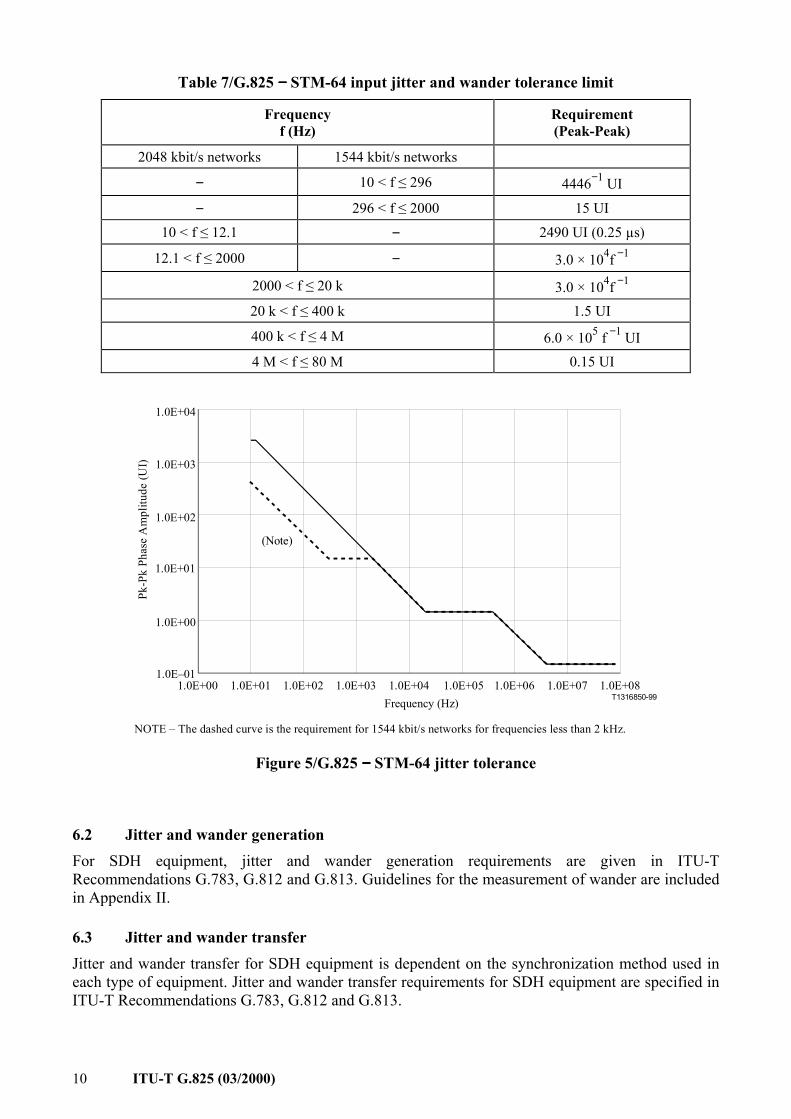
10 ITU-T G.825 (03/2000)
Table 7/G.825 −−−− STM-64 input jitter and wander tolerance limit
Frequency f (Hz)
Requirement (Peak-Peak)
2048 kbit/s networks 1544 kbit/s networks
− 10 < f ≤ 296 4446−1 UI
− 296 < f ≤ 2000 15 UI
10 < f ≤ 12.1 − 2490 UI (0.25 µs)
12.1 < f ≤ 2000 − 3.0 × 10⁴f −1
2000 < f ≤ 20 k 3.0 × 10⁴f −1 20 k < f ≤ 400 k 1.5 UI
400 k < f ≤ 4 M 6.0 × 10⁵ f −1 UI 4 M < f ≤ 80 M 0.15 UI
T1316850-99
1.0E+00
1.0E+01
1.0E+02
1.0E+01 1.0E+03 1.0E+051.0E�01
1.0E+00 1.0E+02 1.0E+04Frequency (Hz)
1.0E+06 1.0E+07
Pk-P
k Ph
ase
Am
plitu
de (U
I) 1.0E+03
1.0E+08
(Note)
1.0E+04
NOTE � The dashed curve is the requirement for 1544 kbit/s networks for frequencies less than 2 kHz.
Figure 5/G.825 −−−− STM-64 jitter tolerance
6.2 Jitter and wander generation For SDH equipment, jitter and wander generation requirements are given in ITU-T Recommendations G.783, G.812 and G.813. Guidelines for the measurement of wander are included in Appendix II.
6.3 Jitter and wander transfer Jitter and wander transfer for SDH equipment is dependent on the synchronization method used in each type of equipment. Jitter and wander transfer requirements for SDH equipment are specified in ITU-T Recommendations G.783, G.812 and G.813.

ITU-T G.825 (03/2000) 11
APPENDIX I
Relationship between network interface jitter requirements and input jitter tolerance
I.1 Network interface jitter requirements For all SDH bit rates, two network limits are specified in Table 1: one for a wide-band measurement filter and one for a high-band measurement filter. The general form of this specification is shown in Table I.1 and is applicable to all SDH rates.
At any SDH network interface, the following output jitter specifications must be met:
Timing jitter as measured over a 60-second interval with a band pass filter with a lower cut-off frequency f1 and a minimum upper cut-off frequency f4 shall not exceed A2 Unit Intervals (UI) peak-to-peak. Also, timing jitter as measured over a 60-second interval with a band pass filter with a lower cut-off frequency f3 and a minimum upper cut-off frequency f4 shall not exceed A1 Unit Intervals (UI) peak-to-peak. The roll off at lower cut-off frequency, f1 and f3, shall be 20 dB/decade. The roll off at the upper cut-off frequency, f4, shall be −60 dB/decade in accordance with ITU-T Recommendation O.172.
Table I.1/G.825 −−−− General form for SDH interface jitter requirements
Measurement filter Measurement bandwidth
Peak-to-peak amplitude (UIpp)
Wide-band f1 to f4 A2 High-band f3 to f4 A1
The value of f1 reflects the narrowest timing circuit cutoff frequency expected in a line system. The timing circuit may time a regenerator's output signal and could be implemented as a Phase-Locked Loop (PLL). Jitter at frequencies higher than the bandwidth of this PLL will be partially absorbed by the PLL's buffer. The portion not absorbed could cause transmission errors due to buffer spill. Jitter at frequencies lower than this bandwidth will simply pass through without affecting transmission performance. The value of f1 therefore represents the narrowest bandwidth that might be used in this output timing circuit. The value of f3 is related to the bandwidth of input timing acquisition circuitry. Jitter at frequencies higher than this bandwidth will constitute alignment jitter and will cause an optical power penalty due to its effect on the eye pattern. This high frequency jitter must therefore be limited to the same degree that equipment specifications limit optical power penalty through jitter tolerance.
The value of f4 reflects reasonable measurement limitations and is listed to establish minimum measurement bandwidth requirements. f4 is chosen to include all expected, significant alignment jitter. A value one decade beyond the widest expected cutoff frequency was chosen (see ITU-T Recommendation G.783).
The values of A1 and A2 are directly related to input sinusoidal jitter tolerance. These parameters have built-in margin and are reasonably conservative because: 1) sinusoidal jitter represents worst case jitter with respect to input jitter tolerance; and 2) accumulated SDH line jitter will not be sinusoidal (instead, it will be noisy).

12 ITU-T G.825 (03/2000)
I.2 Input jitter tolerance of network equipment The general form of the weighting filters used for measuring output jitter at a network interface given in Table I.1 are reproduced below in Figure I.1. The filter responses are given in equations I.2-1 and I.2-2.
T1316860-99f (Hz)
)2(1 ftjH π
)2(2 ftjH π
f1 f3 f4
1
Figure I.1/G.825 −−−− Weighting filters for measuring network interface output jitter
34
24
24
3
34
11
22)(
ω+ω+ω+ω⋅
ω+=
ssssssH (I.2-1)
34
24
24
3
34
32
22)(
ω+ω+ω+ω⋅
ω+=
ssssssH (I.2-2)
443311 222 fff π=ωπ=ωπ=ω
The first term of the function H1(s) represents the phase error transfer function He(s) of some PLL, and its amplitude of A2 = 1.5 UIpp represents its phase error tolerance.
Then the corresponding input phase tolerance of the PLL is given by:
)2(
)(1
21 fjH
AfAtol π= (I.2-3)
Similarly, the input phase tolerance corresponding to H2(s) and its amplitude of A1 = 0.UIpp is given by:
)2(
)(2
12 fjH
AfAtol π= (I.2-4)
These sinusoidal jitter tolerance masks are illustrated in Figure I.2. If unweighted sinusoidal jitter at a network interface satisfies both of these masks, it also satisfies (i.e. lies below) a single mask that is the lower of the two masks for each frequency. Such a combined mask is shown as a dashed curve in Figure I.3.

ITU-T G.825 (03/2000) 13
T1316870-99
f1 f3 f4 f (Hz)
UIpp)(2 fAtol
)(1 fAtol
A2
A1
Amplitude
1.5
0.15
Figure I.2/G.825 −−−− Upper bounds on sinusoidal jitter amplitude
Figure I.3 compares this combined mask with the STM-1(optical) input jitter/wander sinusoidal tolerance mask. They are the same in the range 19.3 < f < 1.3 MHz. In the wander region of phase (f < 19.3 Hz), there are no interface specifications that use weighting filters to check the peak-to-peak phase. (The 10 Hz low-pass wander measurement filter might be considered a weighting filter, but for wander it is MTIE or TDEV that is measured rather than peak-to-peak phase).
T1316880-99
f1 f3 f4f (Hz)
f2
A2
A1
UIpp
0.125 19.3 6.5k 65k 1.3M500
Figure 1/G.825 1.5
0.15
38.9
Amplitude
Lower of Atol1(f) or Atol2(f)
Figure I.3/G.825 −−−− Upper bound on sinusoidal output jitter at an STM-1(Optical) interface [lower of Atol1(f) or Atol2(f)] compared with input jitter/wander tolerance mask

14 ITU-T G.825 (03/2000)
APPENDIX II
Measurement methodology for output wander of synchronous interfaces
Instrumentation in accordance with ITU-T Recommendation O.172 is appropriate for measurement of wander parameters.
When the signal is synchronous (i.e. normally PRC-traceable), and is used to carry synchronization, its wander is measured by comparing its phase with that of another PRC. The test procedure for measuring MTIE of a synchronous signal is shown in Figure II.1 (the standard estimator formula for calculating MTIE is given in Annex B/G.810).
The PRC used for the wander measurement need not be the same as that used to originate the synchronous signal, for most measurement applications. However, it should be noted that the worst-case frequency difference between two PRCs could give rise to a phase difference of the order of 2 µs per day.
T1316890-99
Phase Wander MTIE
PRC
MeasurementReference
Source Reference
PRC
PhaseDetector
10-HzLPF
CalculateMTIE
TransportNetwork
TerminatingElement
Figure II.1/G.825 −−−− MTIE measurement of synchronous signals
APPENDIX III
SDH Line systems and Interworking implications
ITU-T Recommendation G.783 identifies two different types of regenerators, Type A and Type B, which can be used in SDH line systems. The different regenerator types exhibit different jitter characteristics. Type B regenerators exhibit reduced jitter tolerance. Performance penalties due to excessive alignment jitter place restrictions on the use of both Type A and Type B equipment in the same SDH line system. Moreover, the amplitude/frequency characteristics of the accumulated jitter can adversely affect transmission-performance. These limitations must be taken into account by carrier entities who are administering the particular SDH line system.
At network interfaces (e.g. those at international boundaries), STM-N signals must meet interface limits regardless of the individual carrier's equipment choice. It is therefore desirable that the interface requirement is compatible with the type of jitter expected to appear on both Type A and Type B line systems.

ITU-T G.825 (03/2000) 15
Interworking implications Taking into account the characteristics of the Type A and Type B regenerators and the above interface specifications, the following equipment interworking implications can be derived: 1) the magnitude of jitter expected to accumulate on all SDH line systems employing only
Type A equipment falls-within the bounds specified in Table 1; 2) the magnitude of jitter expected to accumulate on all SDH line systems employing only
Type B equipment falls within the bounds specified in Table 1; 3) equipment exhibiting Type A jitter tolerance characteristics will tolerate that jitter which
meets the limits given in Table 1; 4) equipment exhibiting Type B jitter tolerance characteristics will tolerate the jitter expected
to accumulate on Type B SDH line systems. Such equipment, however, may require some jitter reduction for input signals that just approach the limits given for the appropriate line rates in Tables 3, 5, 6 or Table 7. This is expected to be the case when Type B equipment follows a chain of Type A regenerators. This represents the only interworking consideration required by the SDH Interface specifications proposed in this ITU-T Recommendation.

Geneva, 2001
SERIES OF ITU-T RECOMMENDATIONS
Series A Organization of the work of ITU-T
Series B Means of expression: definitions, symbols, classification
Series C General telecommunication statistics
Series D General tariff principles
Series E Overall network operation, telephone service, service operation and human factors
Series F Non-telephone telecommunication services
Series G Transmission systems and media, digital systems and networks
Series H Audiovisual and multimedia systems
Series I Integrated services digital network
Series J Transmission of television, sound programme and other multimedia signals
Series K Protection against interference
Series L Construction, installation and protection of cables and other elements of outside plant
Series M TMN and network maintenance: international transmission systems, telephone circuits, telegraphy, facsimile and leased circuits
Series N Maintenance: international sound programme and television transmission circuits
Series O Specifications of measuring equipment
Series P Telephone transmission quality, telephone installations, local line networks
Series Q Switching and signalling
Series R Telegraph transmission
Series S Telegraph services terminal equipment
Series T Terminals for telematic services
Series U Telegraph switching
Series V Data communication over the telephone network
Series X Data networks and open system communications
Series Y Global information infrastructure and Internet protocol aspects
Series Z Languages and general software aspects for telecommunication systems