t data sheet - intematix · t data s atix comm les luminai iciency loss f white line rent, these...
TRANSCRIPT

Intem
Produc
The Intem
that enab
driver eff
lengths o
drive cur
and effic
consisten
Length o
compone
use of of
DLC or En
Product
In
H
En
co
R
3
1
5
matix C
ct Data S
matix comm
bles luminai
ficiency loss
of white line
rrent, these
iency. Contr
ncy necessar
ptions of 11
ents, further
ff‐the‐shelf o
nergy Star ce
t Features
ntegrated mo
igh efficacy o
nd to end mo
onnectivity
eliable at 200
SDCM Color
1, 22 and 44
Year limited
Comme
heet
mercial lightin
re efficienci
es. The mod
ar lighting.
modules are
rolled to a 3
ry for succes
, 22 and 44
r reducing sy
optic compo
ertification.
dular solutio
of up to 180 lm
ounting and d
0% of rated d
consistency
Inch length o
warranty
ercial
ng module is
es of >130 lu
dule design
Capable of r
e ideal for ap
SDCM color
ssful luminai
inches reduc
ystem costs.
nents. LM80
n
m/W DC
daisy chain
rive current
ptions
Lightin
s a simple an
umens per W
supports en
reliable oper
pplications r
r tolerance t
ires and ligh
ce wiring an
These mod
0 test data is
Ap
ng Mod
nd highly eff
Watt conside
d to end mo
ration at up
equiring ext
hese linear s
ting installat
nd mounting
dules are Zha
s available to
pplication B
Accelerates
Enables 130
Supports de
lines of light
Delivers high
Uniform con
Reduced wir
Design with
dule
ficient plug a
ering typical
ounting, ena
to two time
tremely high
solutions de
tions.
g operation s
aga complia
o accelerate
Benefits
time to mark
lm/W lumina
signs in whic
t are required
h lumen dens
nsistent lighti
ring and mou
confidence
and play solu
optical and
bling unlimi
es their nomi
h lumen dens
eliver the col
steps and
nt, enabling
the path to
ket
aires
h long contin
d
sity
ng
nting costs
ution
ted
inal
sity
or
g the
ward
uous

2 | I n t e m a t i x
Table of Contents
Product Nomenclature 3
Minor Product Change Policy 3
Performance Characteristics 4
Electrical Characteristics 5
Color Binning Information 6
Relative Spectral Power Distribution 7
Intensity Distribution 7
Light Output vs. Drive Current 8
Forward Voltage vs. Forward Current 9
Relative Flux vs. Case Temperature 11
Temperature Ratings 12
Mechanical Characteristics 13
Regulatory Compliance 16
Product Marking 16
Packaging and Labeling 17
Company Information 18
3 | I n t e m a t i x
Product Nomenclature
Intematix Commercial Lighting Module products are identified by the following product
nomenclature:
I L M – A B C D – E F G – H I J K – L M N O
Where:
I L M – Designates the Intematix light module product family
A B – Designates the application
C L = Tunable lighting module
C D – Designates the design version
0 1 = Version 1
E – Designates the first digit in CRI
8 = 80 CRI minimum
F G – Designates the first two digits of the CCT
4 0 = 4000K
H I J K – Designates the nominal lumen output
2 4 0 0 = 2400 lm nominal
L M N O – Designates nominal product length in mm
0 5 6 0 = 560mm (22 inches)
Example:
ILM – CL01 – 840 – 2400 – 0560: Intematix commercial lighting module, design version
1, 80 CRI minimum, 4000K, 2400 nominal lumens, 560mm length
Minor Product Change Policy
The rigorous qualification testing of Intematix products ensures product performance. Slight
cosmetic changes which do not affect the form, fit or function of the product may occur as
Intematix continues product optimization.

4 | I n t e m a t i x
Performance Characteristics
Product Length[2] Drive Current (mA)
Nominal CCT[1]
(K)
Color Consistency[3]
(SDCM)
Min CRI[1,4]
Typical LOP[1,5] (lm)
Typical Efficacy (lm/W)
ILM‐CL01‐830‐1200‐0280 280mm /
11”
350 3000 3 80 1195 175
ILM‐CL01‐840‐1200‐0280 350 4000 3 80 1230 180
ILM‐CL01‐850‐1200‐0280 350 5000 3 80 1230 180
ILM‐CL01‐830‐2400‐0560 560mm /
22”
700 3000 3 80 2390 175
ILM‐CL01‐840‐2400‐0560 700 4000 3 80 2460 180
ILM‐CL01‐850‐2400‐0560 700 5000 3 80 2460 180
ILM‐CL01‐830‐4800‐1120 1120mm /
44”
700 3000 3 80 4780 175
ILM‐CL01‐840‐4800‐1120 700 4000 3 80 4920 180
ILM‐CL01‐850‐4800‐1120 700 5000 3 80 4920 180
Notes:
1. All values included in the table above are pulse tested with case temperature maintained at 25C.
2. Lengths included in the table above are the maximum mechanical length of the product. For more
detailed information please see the mechanical characteristics section of this data sheet.
3. Intematix maintains a tolerance of ± 0.5 SDCM on color consistency measurements.
4. Intematix maintains a ± 3 point tolerance on CRI and R values.
5. Intematix maintains a tolerance of ± 7% of flux measurements.
5 | I n t e m a t i x
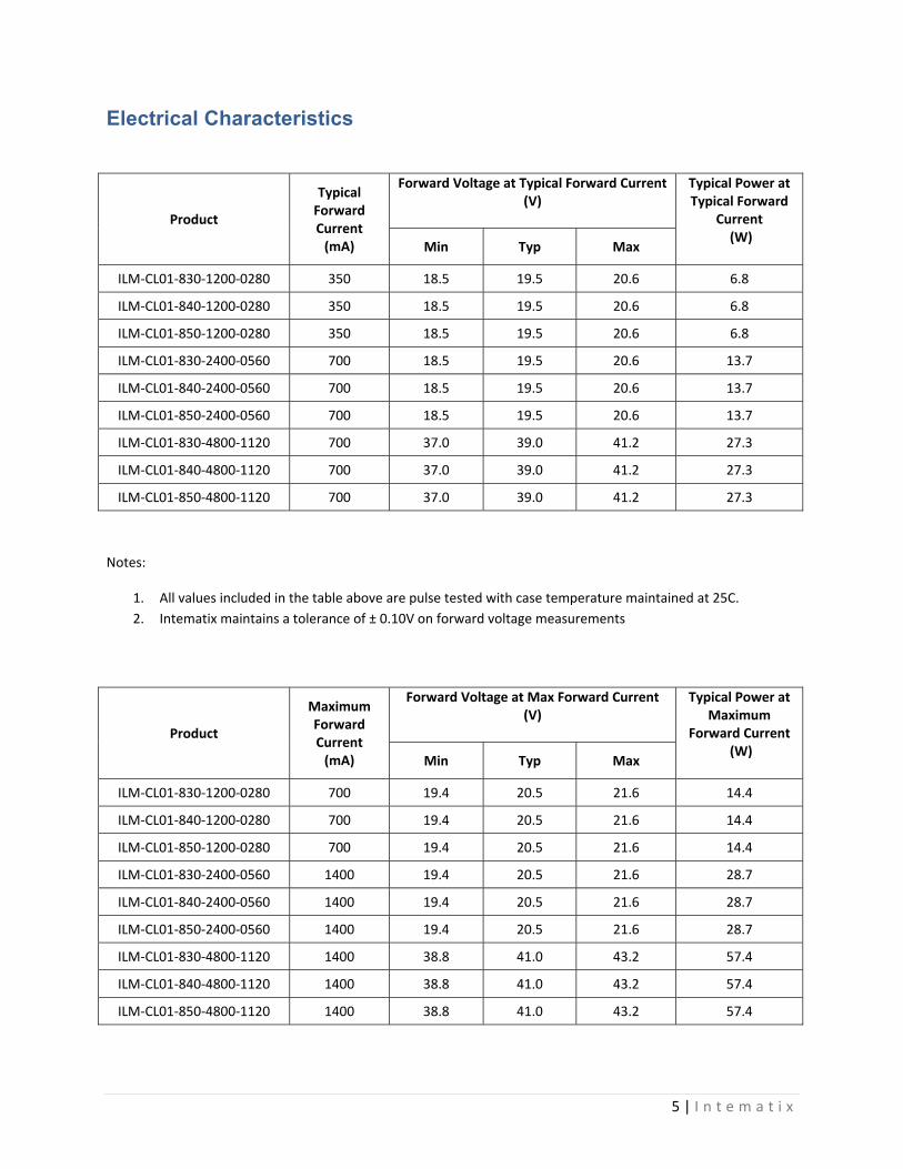
Electrical Characteristics
Product
Typical Forward Current
(mA)
Forward Voltage at Typical Forward Current (V)
Typical Power at Typical Forward
Current (W)
Min Typ Max
ILM‐CL01‐830‐1200‐0280 350 18.5 19.5 20.6 6.8
ILM‐CL01‐840‐1200‐0280 350 18.5 19.5 20.6 6.8
ILM‐CL01‐850‐1200‐0280 350 18.5 19.5 20.6 6.8
ILM‐CL01‐830‐2400‐0560 700 18.5 19.5 20.6 13.7
ILM‐CL01‐840‐2400‐0560 700 18.5 19.5 20.6 13.7
ILM‐CL01‐850‐2400‐0560 700 18.5 19.5 20.6 13.7
ILM‐CL01‐830‐4800‐1120 700 37.0 39.0 41.2 27.3
ILM‐CL01‐840‐4800‐1120 700 37.0 39.0 41.2 27.3
ILM‐CL01‐850‐4800‐1120 700 37.0 39.0 41.2 27.3
Notes:
1. All values included in the table above are pulse tested with case temperature maintained at 25C.
2. Intematix maintains a tolerance of ± 0.10V on forward voltage measurements
Product
Maximum Forward Current
(mA)
Forward Voltage at Max Forward Current (V)
Typical Power at Maximum
Forward Current (W)
Min Typ Max
ILM‐CL01‐830‐1200‐0280 700 19.4 20.5 21.6 14.4
ILM‐CL01‐840‐1200‐0280 700 19.4 20.5 21.6 14.4
ILM‐CL01‐850‐1200‐0280 700 19.4 20.5 21.6 14.4
ILM‐CL01‐830‐2400‐0560 1400 19.4 20.5 21.6 28.7
ILM‐CL01‐840‐2400‐0560 1400 19.4 20.5 21.6 28.7
ILM‐CL01‐850‐2400‐0560 1400 19.4 20.5 21.6 28.7
ILM‐CL01‐830‐4800‐1120 1400 38.8 41.0 43.2 57.4
ILM‐CL01‐840‐4800‐1120 1400 38.8 41.0 43.2 57.4
ILM‐CL01‐850‐4800‐1120 1400 38.8 41.0 43.2 57.4

Color B
Color B
Binning D
Bin Cente
Diagram
er Points
No
s
ominal CCT
3000K
4000K
5000K
CIE x
0.4338
0.3818
0.3447
CIE y
0.4030
0.3797
0.3553
66 | I n t e m aa t i x

Relativ
Intensi
ve Spectr
ity Distrib
ral Power
bution
r Distribuution
77 | I n t e m aa t i x

Light O
Output vs
11
2
s. Drive C
Inch Module
22 Inch Modu
Current
ule
88 | I n t e m aa t i x
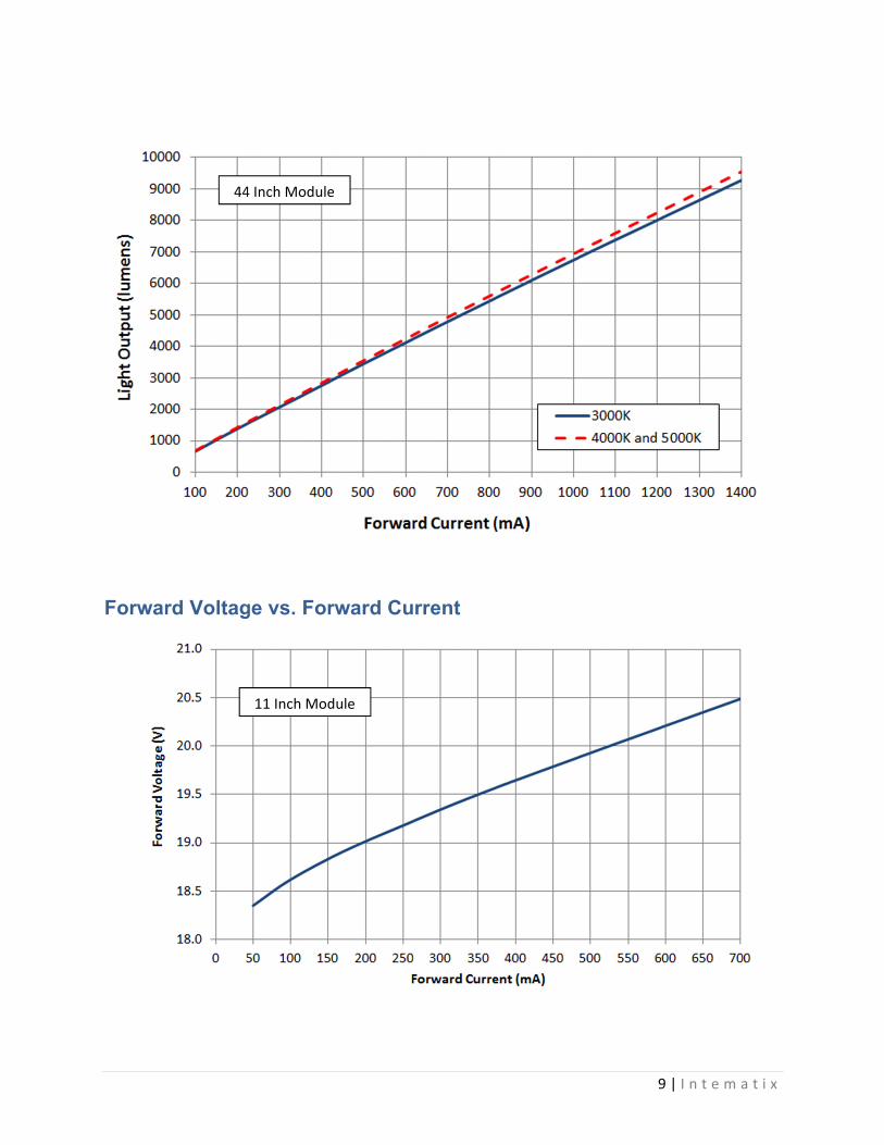
Forwar
rd Voltag
44
ge vs. For
11 Inch Mod
4 Inch Module
rward Cu
dule
e
rrent
99 | I n t e m aa t i x
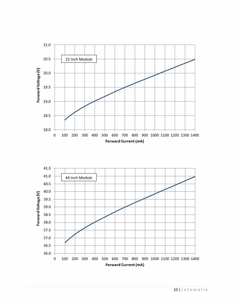
2
4
22 Inch Modu
44 Inch Modu
ule
ule
100 | I n t e m aa t i x

Relativ
ve Flux vss. Case T
Temperature
111 | I n t e m aa t i x

12 | I n t e m a t i x
Temperature Ratings
Description Maximum Rating
Maximum operating case temperature [1] 85°C
Minimum operating case temperature ‐40°C
Maximum storage temperature 85°C
Minimum storage temperature ‐40°C
Soldering Temperature [2] 350°C or lower for a
maximum of 5 seconds
Notes:
1. Case temperature is defined as the temperature measured at the Tc points marked on the printed circuit
board. To measure the case temperature, mount a thermocouple to the Tc point as is indicated on the
product drawing contained in this data sheet.
2. Solder pads are included on the modules for customers that wish to solder wires for electrical connections
rather than using the board mounted connectors.
3. Lumen maintenance and lifetime predictions are valid for the drive current and case temperature
conditions used for LM‐80 testing as is included in the applicable LM‐80 test report for the LED
components used in these linear modules. Please contact your Intematix sales representative for a copy
of the applicable LM‐80 test report.

Mecha
Notes:
1. Cpo
2. D3. D4. M5. O
te6. U
anical Cha
Connectors anolarity.
Drawings are nDrawing dimenMount using MOn board connerminal strip leUnless otherw
aracterist
nd solder pads
not to scale. nsions are in
M4 of #6 mounnectors accepength of 7-9mise specified
tics – 11
s are labeled
millimeters. nting screws ipt an input wirmm.
all tolerances
Inch Mod
“+” to denote
in the cutoutsre cross-secti
s at ± 0.10mm
dule
e positive pola
s provided. ion of 18-24 A
m.
13
arity and “-“ to
AWG (0.2 – 0
3 | I n t e m a
o denote nega
0.75 mm2) with
a t i x
ative
h a

Mecha
Notes:
1. Cpo
2. D3. D4. M5. O
te6. U
anical Cha
Connectors anolarity.
Drawings are nDrawing dimenMount using MOn board connerminal strip leUnless otherw
aracterist
nd solder pads
not to scale. nsions are in
M4 of #6 mounnectors accepength of 7-9mise specified
tics – 22
s are labeled
millimeters. nting screws ipt an input wirmm.
all tolerances
Inch Mod
“+” to denote
in the cutoutsre cross-secti
s at ± 0.10mm
dule
e positive pola
s provided. ion of 18-24 A
m.
14
arity and “-“ to
AWG (0.2 – 0
4 | I n t e m a
o denote nega
0.75 mm2) with
a t i x
ative
h a
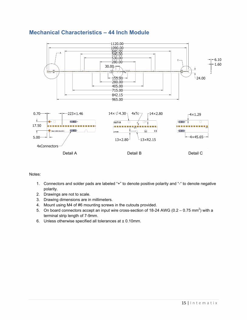
Mecha
Notes:
1. Cpo
2. D3. D4. M5. O
te6. U
anical Cha
Connectors anolarity.
Drawings are nDrawing dimenMount using MOn board connerminal strip leUnless otherw
Deta
aracterist
nd solder pads
not to scale. nsions are in
M4 of #6 mounnectors accepength of 7-9mise specified
ail A
tics – 44
s are labeled
millimeters. nting screws ipt an input wirmm.
all tolerances
Inch Mod
“+” to denote
in the cutoutsre cross-secti
s at ± 0.10mm
Detail
dule
e positive pola
s provided. ion of 18-24 A
m.
B
15
arity and “-“ to
AWG (0.2 – 0
5 | I n t e m a
o denote nega
0.75 mm2) with
Detail C
a t i x
ative
h a

Regula
Produc
Intematix
logo that
This infor
to provid
Intematix
atory Com
Descript
CE
UL and c
Eye Safe
RoHS
REACH
ct Markin
x Commerci
t contains bo
rmation is p
de the produ
x part numb
mpliance
ion
cUL
ety
H
ng
al Lighting M
oth internal
rovided bot
uct part num
ber and the l
8750 Cla
TesFor blue lighoperated at o
Modules are
manufactur
h as legible p
mber and lot
ot number t
Co
IEC 6
ass 2, Suitable
sted in accordht these moduor below the
RoH
REAC
marked wit
ing data as w
print as well
number. Th
that can be u
ompliance
2031 Class III
e for dry and
dance with IEules are ratedspecified ma
S Compliant
CH Compliant
h a label to t
well as usefu
l as a 2D bar
he legible inf
used for trac
16
I
damp locatio
C TR 62778 d Risk Group aximum drive
t
the right of
ul customer
rcode which
formation in
ceability if ne
6 | I n t e m a
ons
1 when current
the Intemat
information
can be scan
ncludes the
eeded.
a t i x
tix
n.
nned

Packag
Intematix
box. The
Only one
included i
included f
The packa
with their
Produ
11 IncModul
22 IncModul
44 IncModul
ging and
x modules a
e box is then
product (part
in a single box
from that spe
aging method
r dimensions,
ct V
ch es
Q
Dim
ch es
Q
Dim
ch es
Q
Dim
Labeling
re packed in
labeled usin
t number) is c
x a label will
ecific lot withi
d is outlined o
is included in
Value
Quantity
mension
Quantity
mension
Quantity
mension
g
n trays. The
ng the follow
contained pe
be applied fo
in the box.
on the followi
n the table be
Tray
40
63 cm x 39 2.4 cm
20
63 cm x 39 2.4 cm
20
119 cm x 392.4 cm
trays are se
wing format
r box. In the
r each lot nu
ing page. The
elow.
cm x m
63
cm x m
63
9 cm x m
13
aled in a bag
:
event that m
mber stating
e quantity of
Box
200
3.5 cm x 41.5 13.5 cm
100
3.5 cm x 41.5 13.5 cm
100
34 cm x 43.5 18 cm
17
g which is th
more than one
the number
parts per tray
cm x 13
cm x 13
cm x 13
7 | I n t e m a
hen placed in
e lot number
of products
y and box, alo
Shipping Bo
400
34 cm x 43.5 c18 cm
200
34 cm x 43.5 c18 cm
100
34 cm x 43.5 c18 cm
a t i x
n a
is
ong
ox
cm x
cm x
cm x

Compa
Intematix
consisten
phospho
solutions
a materia
modules
company
46410 Frem
Fremont, C
Tel: +1 (51
Fax: +1 (51
sales@inte
©2017 Int
Last updat
any Infor
x products e
ncy, uniform
r componen
s serving ma
als innovato
also acceler
y please visit
mont Bouleva
CA 94538
10) 933‐3300
10) 668‐0793
ematix.com
ematix, Inc. A
ted October 1s
mation
enable attrac
mity and relia
nts and mod
rkets includ
r, the integr
rates time‐to
t www.intem
rd
All rights reservt, 2017
ctive lighting
ability. By pr
ules, Intema
ing general a
ration of our
o‐market an
matix.com.
ved. Product s
g system des
roviding cust
atix products
and specialt
r broad selec
d reduces sy
specifications
signs, vivid c
tomized and
s serve as th
ty lighting, d
ction of phos
ystem costs.
are subject to
18
color quality
d patented p
he foundatio
isplays, and
sphors into
. To learn m
change witho
8 | I n t e m a
, and superi
phosphors,
on for lightin
automotive
components
more about t
out notice.
a t i x
or
g
e. As
s and
he