t 1000 plus - isa advanced test & diagnostic systems 1000plus/pdf/inglese/t1000plus.pdf · t...
TRANSCRIPT

w w w . i s a t e s t . c o m
T 1 0 0 0 P L U S
SECONDARY INJECTION RELAY TEST SET

2
T 1000 PLUS
• Designed for testing relays and transducers
• Microprocessor controlled
• With phase angle shifter
• Frequency generator
• Test results and settings are saved into local memory
• High power outputs
• Oscilloscope function for current and voltage
• Large graphical display
• Compact and lightweight
• Possibility to synchronize several T 1000 PLUS test sets
• USB interface
• 2 auxiliary contacts for the test of autoreclosers
A P P L I C A T I O N
RELAY TYPE IEEE NO
Distance relay (3 sets) 21Synchronizing device 25Thermal 26Under/over-voltage relay 27/59Directional Power relay 32/92Undercorrent 37Negative sequence over-currrent 46Phase sequence voltage relay 47Incomplete sequence relay 48Definite time over-current relay 50/50NInverse time over-current relay 51/51NPower factor relay 55Voltage balance relay 60Ground detector relay 64Directional over-current relay 67Directional earth fault 67NAutomatic reclosing 79Frequency relay 81>/81<Load shed 81RPilot wire receiver relay 85Motor protection 86Differential protection relay (TD 1000) 87Voltage directional relay 91Tripping relay 94
The relay test set T 1000 PLUS is suited for the testing of the following types of relays:
Secondary injection relay test set
The instrument contains three separate generators:. Main generator, that generates either AC current, AC voltage; DC voltage;. Auxiliary AC voltage generator, that generates an independent, phase shiftable AC voltage;. Auxiliary DC voltage generator, that generates the DC voltage that powers the relay under test.
All outputs are adjustable and metered at the same time on the large, graphic LCD display.
T 1000 PLUS can operate without connection to a PC. With the multi-purpose knob and the LCD display it is possible to enter the MENU mode, that allows to set many functions, that make T 1000 PLUS a very powerful testing device, with manual and semi-automatic testing capabilities, and with the possibility to transfer test results to a PC via USB interface. These results can be recorded, displayed and analysed by the powerful TDMS sof-tware, that operates with all WINDOWS versions, starting from WINDOWS 98 included.
D E S C R I P T I O N

3
T 1000 PLUS Secondary injection relay test set
TDMS
S P E C I F I C A T I O NMain generatorThe main generator has three outputs: currents, voltage AC, voltage DC. The following specifications apply to the separate usage of these outputs.
AC current outputs
100 30 300 steady - 100 800 60 15 250 1000 1 5 40 12 300 steady - 40 800 60 15 80 1000 1 5 10 5 400 steady - 10 800 60 15 20 1000 2 5
RANGE CURRENT MAXIMUM LOAD RECOVERYA OUTPUT POWER TIME TIMEAC A VA s min
AC voltage outputs
250 250 500 steady - 250 750 10 45
RANGE VOLTAGE MAXIMUM LOAD RECOVERYV OUTPUT POWER TIME TIMEAC V VA min min
DC voltage outputs
Other features of main outputs. Zero crossing control. Main AC outputs are generated and stopped as the output waveform crosses zero. . High resolution adjustment control.. Overload alarm message. . Thermal protection.. Possibility to reduce the output power to one fifth for low burdens.
Auxiliary AC voltage output. The auxiliary AC voltage output is isolated from the main AC current and voltage.. Range selection: software driven, by the multi-function knob and LCD display.. Auxiliary voltage power: 30 VA, continuous duty, at full range; 40 VA for 1 minute. . Push-button to enable or disable the output.
Auxiliary AC voltage output
65 40 130 40 260 40
RANGE V MAX POWER VA
Phase angle shifting. Possibility to phase shift the auxiliary AC voltage output with respect to the main current or voltage. . Phase angle adjustment: via the multi-function knob.. Phase angle range: from 0° to 360°.. Adjustment resolution: 1° (degree).
Frequency generator & frequency r.o.c.. Possibility to change the frequency of the auxiliary AC voltage output. Frequency generation characteristics:. Frequency range: 15 Hz to 550 Hz.. Frequency adjustment: 1 mHz.. Rate of change: 1 mHz/s to 99.99 Hz/s.
Auxiliary DC voltage output. DC voltage range: 10...130 V or 20...240 V.. DC voltage power: 90 W at full range, continuous duty, with a current limit of 0.9 A @ 130 V and 0.45 A @ 240 V.. Push-button to enable or disable the output
TimerThe electronic digital timer has a fully automatic start and stop, both for make and break of the input, that can be either a clean (dry) contact or a contact under voltage (wet).. Metering range, can also be performed in cycles.. Possibility to test automatic reclosers.. Maximum number of reclosing commands: 99.
2 auxiliary contacts are available. Contacts range: 5 A; 250 V AC; 120 V DC.
300 300 300 steady - 300 500 10 45
RANGE VOLTAGE MAXIMUM LOAD RECOVERYV OUTPUT POWER TIME TIMEDC V W min min
From 0 to 9.999 s 1 ms ± (1 ms + 0.005%) From 10.0 to 99.99 s 10 ms ± (10 ms + 0.005%)From 100.0 to 999.9 s 100 ms ± (100 ms + 0.005%)From 1.000 to 9.999 s 1 s ± (1 s + 0.005%)
RANGE RESOLUTION ACCURACY
4
T 1000 PLUS
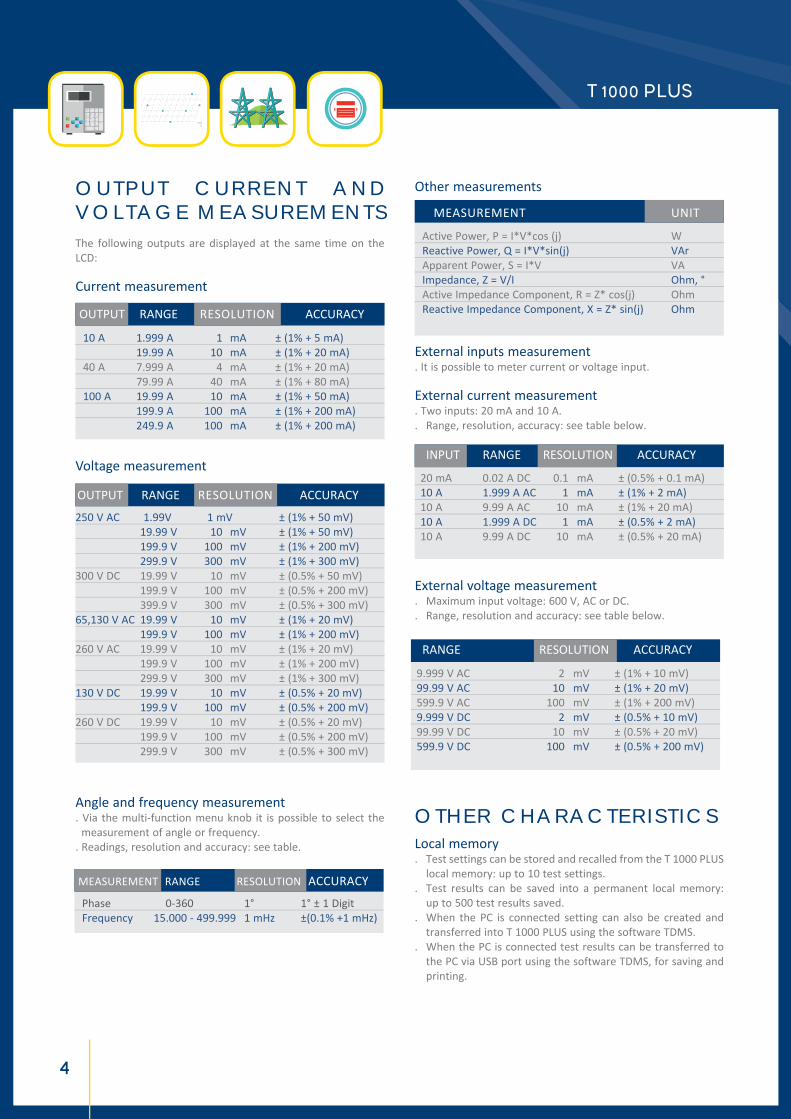
O U T P U T C U R R E N T A N D V O L T A G E M E A S U R E M E N T SThe following outputs are displayed at the same time on the LCD:
Current measurement
OUTPUT RANGE RESOLUTION ACCURACY
10 A 1.999 A 1 mA ± (1% + 5 mA) 19.99 A 10 mA ± (1% + 20 mA) 40 A 7.999 A 4 mA ± (1% + 20 mA) 79.99 A 40 mA ± (1% + 80 mA) 100 A 19.99 A 10 mA ± (1% + 50 mA) 199.9 A 100 mA ± (1% + 200 mA) 249.9 A 100 mA ± (1% + 200 mA)
Voltage measurement
Angle and frequency measurement. Via the multi-function menu knob it is possible to select the measurement of angle or frequency. . Readings, resolution and accuracy: see table.
Other measurements
Active Power, P = I*V*cos (j) W Reactive Power, Q = I*V*sin(j) VAr Apparent Power, S = I*V VA Impedance, Z = V/I Ohm, ° Active Impedance Component, R = Z* cos(j) Ohm Reactive Impedance Component, X = Z* sin(j) Ohm
MEASUREMENT UNIT
External inputs measurement . It is possible to meter current or voltage input.
External current measurement. Two inputs: 20 mA and 10 A.. Range, resolution, accuracy: see table below.
External voltage measurement. Maximum input voltage: 600 V, AC or DC.. Range, resolution and accuracy: see table below.
O T H E R C H A R A C T E R I S T I C SLocal memory. Test settings can be stored and recalled from the T 1000 PLUS local memory: up to 10 test settings.. Test results can be saved into a permanent local memory: up to 500 test results saved.. When the PC is connected setting can also be created and transferred into T 1000 PLUS using the software TDMS.. When the PC is connected test results can be transferred to the PC via USB port using the software TDMS, for saving and printing.
OUTPUT RANGE RESOLUTION ACCURACY
250 V AC 1.99 V 1 mV ± (1% + 50 mV) 19.99 V 10 mV ± (1% + 50 mV) 199.9 V 100 mV ± (1% + 200 mV) 299.9 V 300 mV ± (1% + 300 mV)300 V DC 19.99 V 10 mV ± (0.5% + 50 mV) 199.9 V 100 mV ± (0.5% + 200 mV) 399.9 V 300 mV ± (0.5% + 300 mV)65,130 V AC 19.99 V 10 mV ± (1% + 20 mV) 199.9 V 100 mV ± (1% + 200 mV)260 V AC 19.99 V 10 mV ± (1% + 20 mV) 199.9 V 100 mV ± (1% + 200 mV) 299.9 V 300 mV ± (1% + 300 mV)130 V DC 19.99 V 10 mV ± (0.5% + 20 mV) 199.9 V 100 mV ± (0.5% + 200 mV)260 V DC 19.99 V 10 mV ± (0.5% + 20 mV) 199.9 V 100 mV ± (0.5% + 200 mV) 299.9 V 300 mV ± (0.5% + 300 mV)
MEASUREMENT RANGE RESOLUTION ACCURACY
Phase 0-360 1° 1° ± 1 Digit Frequency 15.000 - 499.999 1 mHz ±(0.1% +1 mHz)
20 mA 0.02 A DC 0.1 mA ± (0.5% + 0.1 mA) 10 A 1.999 A AC 1 mA ± (1% + 2 mA) 10 A 9.99 A AC 10 mA ± (1% + 20 mA) 10 A 1.999 A DC 1 mA ± (0.5% + 2 mA) 10 A 9.99 A DC 10 mA ± (0.5% + 20 mA)
INPUT RANGE RESOLUTION ACCURACY
9.999 V AC 2 mV ± (1% + 10 mV) 99.99 V AC 10 mV ± (1% + 20 mV) 599.9 V AC 100 mV ± (1% + 200 mV) 9.999 V DC 2 mV ± (0.5% + 10 mV) 99.99 V DC 10 mV ± (0.5% + 20 mV) 599.9 V DC 100 mV ± (0.5% + 200 mV)
RANGE RESOLUTION ACCURACY

5
T 1000 PLUS Secondary injection relay test set
TDMS
ResistorsA set of resistors is supplied for the test of low impedance relays. Available values:
0,5 50 10 1 50 7 22 50 2.15 470 50 0.33 1000 50 0.22 2200 50 0.15
RESISTANCE OHM POWER W MAX CURRENT A
Interface. Interfaces for connection to PC: USB.
Power supply. Mains supply to be clearly indicated in purchase order: 230 V ± 15% 50-60 Hz or 120 V ± 15%50-60 Hz. Maximum supply current: 5 A.
Standard accessoriesThe instrument comes complete with the following items: . Set of standard test cables. Mains cable. USB cable. User’s manual. Spare fuses (no. 5), T5A. Software TDMS with serial cable.
Weight and dimension. Dimensions: 380 (w) x 300 (d) x 240 (h) mm.. Weight: 19 kg.
CaseAlluminium case with cover and handle.
T D 1 0 0 0 P L U SWith two current outputs to test differential relay
TD 1000 Plus has two current outputs to test differential relay characteristic curve and not only the pick-up current. In addition, the frequency of this current can be changed as with voltages: this allows to test the second harmonic restraint characteristic of the differential relay. Last, the steady voltage output power is increased from 30 VA to 50 VA.
. Auxiliary AC voltage. Power: 40 VA, continu-ous duty, at full range; 50 VA for 1 minute. For lower voltages the limiting current is the following.
20 3
MAX CURRENT A VOLTAGE V
All other performances are the same as T 1000 Plus.
The request of this model must be specified at order.
TDMS - Relay Test Result

6
T 1000 PLUS
T D 1 0 0 0 P L U S 1 5 H ZWith two current outputs to test differential relay and with high power at 15 Hz
TD 1000 Plus 15 Hz is identical to TD 1000 Plus except for the high power and full range at 15 Hz. This allows testing old railway and generator protection relays. TD 1000 Plus 15 Hz does NOT have the DC battery simulator.
. Power at 15 Hz: 25 VA on all ranges.
. No Auxiliary DC voltage supply.
. Weight: 21 kg.All other performances are the same as T 1000 Plus.The request of this model must be specified at order.
T 1 0 0 0 E P L U SHigher AC voltage outputs
In this model, AC voltage outputs are higher than in the stand-ard version.. Main AC voltage output. . Auxiliary AC voltage. Power: 30 VA, continuous duty, at full range; 40 VA for 1 minute. For lower voltages the limiting cur-rent is the following.
All other performances are the same. The request of this model must be specified at order.
O P T I O N SHeavy duty transport caseHeavy duty transport case in black plastics, with wheels, cover and handle.
Connection cablesThe kit includes cables for any kind of connection.
65 500 130 250 500 62
RANGE V MAX CURRENT mA
T 1000 PLUS - Optional cable kit
T 1000 PLUS - Standard cable kit
Heavy duty transport case

7
T 1000 PLUS Secondary injection relay test set
TDMS
D 1000 Differential relay test moduleThe differential relay test module D 1000 allows the test of the differential relay curve and also of the harmonic restraint characteristic.The module performances are the followings:. Input: from the test set auxiliary AC voltage output.. Output: 0 to 5 A CA.. Output power: 5 VA. . Dimension: 325 x 290 x 290 mm.. Weight: 7 kg.
FT 1000 current filter This external module removes AC current distortions. It isconnected in series to the relay under test, and guarantees a sinusoidal waveform also when testing current relays with reverse time characteristics, or with heavily saturating burdens, that tend to distort the current waveform.. Current input ranges: 0.5 - 2 - 10 - 50 - 100 - 200 A, on termi-nal bushings.. Maximum power yield: 800 VA.. Filter burden: less than 200 VA at 200 A. The burden is pro-portional to the range (50 VA at 50 A).. Service: 50 A continuous service; 200 A for 30 s.. Selection of the mains frequency: 50 or 60 Hz, by switch.. Dimensions: 220 x 250 x 310 mm.. Weight: 15 kg.
SHA 1000 scanning headSHA 1000 is a scanning head that eases the test of energy meters. It is an universal scanning head because it can be used both with LED impulse electronic meters and Ferraris rotating disk meters; selection is performed via a switch located on the scanning head. In addition to this, a knob allows to adjust the sensitivity of the head. With rotating disk the sensor uses a green light beam that optimizes the recognition of any type of mark. With LED recognition the following specification applies:. Impulse duration: more than 60 us;
D 1000 Differential relay test module
. With an LED signal having a space ratio 1:2, the frequency must be less than 500 Hz.;. Light wavelength: 500 to 960 nm (red: green and blue ARE NOT detected).
Outputs transducer for low level signal relaysThe outputs transducer is an option that allows converting the high current and voltage outputs into low voltage signals. The option is made of three components:· The Outputs transducer, complete with the interface connector;· The connection cable from the transducer to a two BNC connectors and one RJ-45 connector, for the ABB relays REF542PLUS and REF601;· The connection cable from the transducer to one RJ-45 connector, for the THYSENSOR series of THYTRONIC relays.The items can be ordered separately: the Output transducer alone, or also one cable or both.
A P P L I C A B L E S T A N D A R DThe test set conforms to the EEC directives regarding Electromagnetic Compatibility and Low Voltage instruments.. Electromagnetic Compatibility: Directive no. 2004/108/EC . Low Voltage Directive: Directive n. 2006/95/EC. Applicable standards, for a class I instrument, pollution degree 2, Installation category II:. CEI EN 61010-1. In particular:. Inputs/outputs protection: IP 2X - CEI 70-1.. Operating temperature: 0 to 50°C; storage: -40°C to 70°C.. Relative humidity: 5 - 95% without condensing.
Output transducer module

T 1000 PLUS
T 1000 PLUS / T 1000 E PLUS / TD 1000 PLUS FAMILY - FEATURES COMPARISON TABLEMAIN I AC
MAX A
AUX I/V AC POWER@ 15 Hz
VA
MAIN V AC
MAX V
MAIN V DC
MAX V
AUX V AC
MAX V
AUX I AC
T 1000 Plus 160 250 300 250 - 10 240 120 V T 1000 Plus 250 250 300 250 - 10 240 230 V T 1000 E Plus 250 500 300 500 - 10 240
TD 1000 Plus 160 250 300 250 20 10 240 120 V
TD 1000 Plus 250 250 300 250 20 10 240 230 V
TD 1000 Plus 15 Hz 160 250 300 250 20 25 - 120 V
TD 1000 Plus 15 Hz 250 250 300 250 20 25 - 230 V
AUX V DC
MAX V
CODE MODULE 91093 T 1000 PLUS complete with Software TDMS and standard set of cables - 230V 81093 T 1000 PLUS complete with Software TDMS and standard set of cables - 120V 94093 TD 1000 PLUS complete with Software TDMS and standard set of cables - 230V 96093 TD 1000 PLUS complete with Software TDMS and standard set of cables - 120V 93093 TD 1000 PLUS 15 Hz complete with Software TDMS and standard set of cables - 230V 95093 TD 1000 PLUS 15 Hz complete with Software TDMS and standard set of cables - 120V 92093 T 1000 E PLUS (500V Aux Voltage outputs) complete with Software TDMS and standard set of cables- 230 V
CODE MODULE 17093 Heavy Duty Transport Case 18093 Set of additional test cables for models T 1000 PLUS / T 1000-E PLUS / TD 1000 PLUS 40093 D 1000 differential relay test module 16093 FT 1000 Mains Filter Unit 43102 SHA 1000 scanning head 13093 Outputs transducer with interface connector and cables 11093 Connection cable and RJ-45 connector for ABB relays (REF542PLUS and REF601) 12093 Connection cable for THYTRONIC relays (Thysensor series)
ORDERING INFORMATION
EN -
T 1
000
plus
-
02/2
016 The document is subject to change without notice.
Always refer to our technical specification for more detailed information and as formal contract document.
I.S.A. srlvia Prati Bassi 2221020 Taino (VA) ITALY T +39 0331 956081 F +39 0331 [email protected]