systems systemssystems inc. inc.inc. documents/800 sbii...systemssystems inc.inc. systems inc. ......
TRANSCRIPT
8625 Industrial Parkway Angola, NY 14006-9696 (716) 549-4700 24-hr Fax (716) 549-4772A Member of Bird Technologies Group
SYSTEMSSYSTEMSINC.INC.
SYSTEMSINC.
Installation and Operation Manualfor the Two-Way Signal Booster System
Model Number 61-89A-50-XXX-XX

TX RX SYSTEMS INC. 8625 INDUSTRIAL PARKWAY, ANGOLA, NY 14006-9696TELEPHONE 716-549-4700 FAX 716-549-4772 (24 HRS)
A MEMBER OF BIRD TECHNOLOGIES GROUP
SYSTEMSINC.
SYSTEMSINC.
SYSTEMSINC.
SYSTEMSINC.
TUNING
INSTALLATION
ASSEMBLY
•
•
•Part No.
Installation and Operation Manual for the Two-Way Signal Booster System
Model Number 61-89A-50-XXX-XX
First Printing: March 2004
7-9362-1.2
Version Number Version Date
1 03/30/04
1.2 04/15/04
Copyright © 2004 TX RX Systems Inc.

NOTE
WARNING
WarrantyThis warranty applies for one year from shipping date.
TX RX Systems Inc. warrants its products to be free from defect in material and workman-ship at the time of shipment. Our obligation under warranty is limited to replacement orrepair, at our option, of any such products that shall have been defective at the time ofmanufacture.TX RX Systems Inc. reserves the right to replace with merchandise of equal performancealthough not identical in every way to that originally sold.TX RX Systems Inc. is not liable for damage caused by lightning or other natural disasters.No product will be accepted for repair or replacement without our prior written approval.The purchaser must prepay all shipping charges on returned products. TX RX SystemsInc. shall in no event be liable for consequential damages, installation costs or expense ofany nature resulting from the purchase or use of products, whether or not they are used inaccordance with instructions. This warranty is in lieu of all other warranties, either ex-pressed or implied, including any implied warranty or merchantability of fitness. No repre-sentative is authorized to assume for TX RX Systems Inc. any other liability or warrantythan set forth above in connection with our products or services.
Terms and Conditions of Sale
PRICES AND TERMS: Prices are FOB seller’s plant in Angola, NY domestic packagingonly, and are subject to change without notice. Federal, State and local sales or excisetaxes are not included in prices. When Net 30 terms are applicable, payment is duewithin 30 days of invoice date. All orders are subject to a $100.00 net minimum.QUOTATIONS: Only written quotations are valid.ACCEPTANCE OF ORDERS: Acceptance of orders is valid only when so acknowledgedin writing by the seller.SHIPPING: Unless otherwise agreed at the time the order is placed, seller reserves theright to make partial shipments for which payment shall be made in accordance withseller’s stated terms. Shipments are made with transportation charges collect unlessotherwise specified by the buyer. Seller’s best judgement will be used in routing, exceptthat buyer’s routing is used where practicable. The seller is not responsible for selectionof most economical or timeliest routing.CLAIMS: All claims for damage or loss in transit must be made promptly by the buyeragainst the carrier. All claims for shortages must be made within 30 days after date ofshipment of material from the seller’s plant.SPECIFICATION CHANGES OR MODIFICATIONS: All designs and specifications ofseller’s products are subject to change without notice provided the changes or modifi-cations do not affect performance.RETURN MATERIAL: Product or material may be returned for credit only after writtenauthorization from the seller, as to which seller shall have sole discretion. In the eventof such authorization, credit given shall not exceed 80 percent of the original purchase.In no case will Seller authorize return of material more than 90 days after shipment fromSeller’s plant. Credit for returned material is issued by the Seller only to the originalpurchaser.ORDER CANCELLATION OR ALTERATION: Cancellation or alteration of acknowledgedorders by the buyer will be accepted only on terms that protect the seller against loss.NON WARRANTY REPAIRS AND RETURN WORK: Consult seller’s plant for pricing.Buyer must prepay all transportation charges to seller’s plant. Standard shipping policyset forth above shall apply with respect to return shipment from TX RX Systems Inc. tobuyer.
Disclaimer
Product part numbering in photographs and drawings is accurate at time of printing.Part number labels on TX RX products supercede part numbers given within this manual.Information is subject to change without notice.
SymbolsCommonly Used
CAUTION orATTENTION
High Voltage
Use SafetyGlasses
ESDElectrostaticDischarge
Hot Surface
Electrical ShockHazard
ImportantInformation

To satisfy FCC RF exposure requirements for mobile trans-mitting devices, a separation distance of 1.0 Meters or moreshould be maintained between the UPLINK antenna of thisdevice and persons during device operation. To satisfy FCCRF exposure requirements for mobile transmitting devices, aseparation distance of 0.2 Meters or more should be main-tained between the DOWNLINK antenna of this device andpersons during device operation. To ensure compliance,operations at closer than these distances is not recom-mended.
The antenna used for this transmitter must not be co-locatedin conjunction with any other antenna or transmitter.
WARNING
For Class A Unintentional RadiatorsThis equipment has been tested and found to comply with the limits for a Class A digital device, pursuant topart 15 of the FCC rules. These limits are designed to provide reasonable protection against harmful inter-ference when the equipment is operated in a commercial environment. This equipment generates, uses,and can radiate radio frequency energy and, if not installed and used in accordance with the instructionmanual, may cause harmful interference to radio communications. Operation of this equipment in a resi-dential area is likely to cause harmful interference in which case the user will be required to correct theinterference at his own expense.
Changes or modifications not expressly approved by TXRX System Inc. could void the user’s authority to operatethe equipment.
WARNING
This device complies with Part 15 of the FCC Rules. Operation is subject to thefollowing two conditions: (1) this device may not cause harmful interference and(2) this device must accept any interference received, including interferencethat may cause undesired operation.

Antenna System Installation
The antenna or signal distribution system consists of two branches. An uplinkbranch typically uses an outdoor mounted, unidirectional gain antenna suchas a yagi and a downlink signal radiating system consisting of a network ofzero-gain whip antennas or lengths of radiating cable usually mounted insideof the structure.
Even though the antenna system may not be supplied or installed by TX RXSystems. The following points need to be observed because both the safetyof the user and proper system performance depend on them.
1) Antenna system installation should only be performed by qualified techni-cal personnel.
2) The following instructions for your safety describe antenna installationguidelines based on FCC Maximum RF Exposure Compliance require-ments.
3) The uplink antenna is usually mounted outside and exchanges signalswith the repeater base station or donor site. It is typically mounted perma-nently-attached to the building wall or roof. The gain of this antenna shouldNOT exceed 10 dB. Only qualified personnel should have access to theantenna and under normal operating conditions, no one should be able totouch or approach it within 1 meter (40 inches).
4) The downlink or in-building signal distribution system is connected to thedownlink booster port using coaxial cable. The distribution system mayuse radiating coaxial cable or a network 1/4 wave whip antennas whosegain does not exceed 0 dB for any radiator. These antennas should beinstalled so that the user cannot approach any closer than 0.2 meters (8inches) from the antenna.

Table of Contents
General Description ..............................................................................................1Unpacking .......................................................................................................1Installation .......................................................................................................1 Location .......................................................................................................1 Mounting .......................................................................................................3Connections .......................................................................................................5 AC Line .......................................................................................................5 Backup DC Power..................................................................................................5 Alarm Terminals (Form-C Contacts) ......................................................................5 RF Connections.....................................................................................................6 Pre-RF Connection Testing...................................................................................6 Test Equipment ......................................................................................................6 Antenna Isolation...................................................................................................6 Procedure for Measuring Antenna Isolation ..........................................................6 Increase isolation or decrease gain?.....................................................................7Normal Operation ..................................................................................................7 LED Status Indicators............................................................................................8 Front Panel LED’s ................................................................................................8 Module LED’s ......................................................................................................8 OLC Light Bars ....................................................................................................8 Front Panel Controls & the LCD Display................................................................8 LCD Display Screen ..............................................................................................10 Configuration Settings ...........................................................................................10 Restore Original Configuration ...........................................................................10 Calibrate Currents ..............................................................................................10 Set Gain .......................................................................................................10 Set Output Level .................................................................................................10 Change Gain Configuration ................................................................................10 Detailed Status Screens ........................................................................................11 Amplifiers .......................................................................................................11 Power Supply......................................................................................................11 OLC .......................................................................................................11 OLC Datalog.......................................................................................................11Alarms .......................................................................................................11 LED Indicators .......................................................................................................11 Form-C contacts ....................................................................................................12Performance Survey..............................................................................................12Maintenance and Repair .......................................................................................13 Power Amplifier Replacement................................................................................14 Module Replacement.............................................................................................15 Display/User Interface Replacement .....................................................................16 Power Supply Replacement...................................................................................17 Duplexer / Filter Replacement ...............................................................................17 Card Cage Replacement .......................................................................................17Recommended Spares..........................................................................................17
Manual 7-9362-1.2 04/15/04 Table of Contents

Figures and TablesFigure 1 Cabinet mounting hole layout 3Figure 2 Front internal cabinet view 4Figure 3 AC power entry 5Figure 4 Measuring antenna isolation 7Figure 5 Boot-up display 7Figure 6 Operational status display 8 Figure 7 Menu System 9Figure 8 Measuring Booster Gain 12Figure 9 Performance Survey 13Figure 10 Removing the Power Amplifier (1 of 3) 14Figure 11 Removing the Power Amplifier (2 of 3) 14Figure 12 Removing the Power Amplifier (3 of 3) 15Figure 13 Disconnecting Display/User Interface 16
Table 1 Model Number Designations 1Table 2 Model 61-89A-50-XXX-XX 2
Specifications 18Block Diagram High Gain (1 of 4) 19Block Diagram Med Gain (2 of 4) 20Block Diagram Low Gain (3 of 4) 21Block Diagram (4 of 4) 22Celsius to Fahrenheit Conversions 23
Manual 7-9362-1.2 04/15/04 Table of Contents
GENERAL DESCRIPTIONSignal boosters extend radio coverage into areaswhere abrupt propagation losses prevent reliablecommunication. No frequency translation (conver-sion) occurs with this device. Signal Booster II (SBII) is a broadband, bi-directional signal boosteravailable in a variety of configurations as shown inTable 1. The product model number is used todescribe each configuration available. This manualdetails the installation and operation of the 61-89A-50-XXX-XX series of boosters. The complete prod-uct family for the 61-89A-50-XXX-XX boosters arelisted in Table 2.
The system can be ordered in one of three maxi-mum gain configurations including Full Gain (+80dB gain max), Medium Gain (+60 dB gain max),and Low Gain (+45 dB max gain). The maximumgain of the system is determined by the exact typeof cards plugged into the low and mid level slots asshown in the block diagrams at the back of thismanual. The maximum gain of the uplink or down-link branch is adjustable and can be setup inde-pendently. In addition, the gain of each branch canbe reduced up to 30 dB in 0.5 dB increments viasoftware interface.
The bandwidth of the system is determined by thepassband of the input/output filtering. The filterspassband is determined by its physical construc-tion so must be determined at the time of order. Asshown in table 1 the system may be ordered in anyof five different bandwidths including 18, 15, 10, 5,and 3 MHz.
Three cabinet styles are available. The G1 suffixdenotes a NEMA-4 style cabinet which is suitablefor indoor or outdoor use. The G2 suffix denotes astainless steel NEMA-4X style cabinet suitable forcorrosive environments such as salt air and the RMsuffix a rack mount version which is intended forindoor mounting only.
UNPACKINGIt is important to report any visible damage to thecarrier immediately. It is the customer's responsibil-ity to file damage claims with the carrier within ashort period of time after delivery (1 to 5 days).Care should be taken when removing the unit fromthe packing box to avoid damage to external heat-sink fins. Use caution because the heatsink finscan have somewhat sharp corners. Signal BoosterII (SB II) weighs about 85 lbs. so use enough peo-ple when lifting the unit.
INSTALLATIONThe following sections discuss general consider-ations for installing the booster. All work should beperformed by qualified personal in accordance withlocal codes.
LocationThe layout of the signal distribution system will bethe prime factor in determining the mounting loca-tion of Signal Booster II. However, safety and ser-viceability are also key considerations. The unitshould be located where it cannot be tamperedwith by the general public, yet is easily accessibleto service personnel. Also consider the weight of
61 - 89A - 50 - A18 - G1 (Example)
FAMILY FREQUENCYBAND
MODEL COARSEGAIN
BANDWIDTH ENCLOSURETYPE
60 =61 =
612 =
1 Way2 Way2 Wayw/FiberInterface
89A = 806 - 824851 - 869
50 = SignalBooster II
A =B =C =
80 dB60 dB45 dB
18 = 18 MHz15 = 15 MHz10 = 10 MHz05 = 5 MHz03 = 3 MHz (NPSPAC)
G1 =G2 =RM =
Painted, Nema4Stainless, Nema4XRack Mount
Table 1: Model number designations. Model 61-89A-50-A18-G1 shown as example.
*
*Note: Gain of 80 dB model set to 50 dB at factory. Please measure antenna isolation before resetting.
GAI
GAIN
Manual 7-9362-1.2 Page 1TX RX Systems Inc. 04/15/04

Manual 7-9362-1.2 Page 2TX RX Systems Inc. 04/15/04
Model Gain Pass Bandwidth (MHz) Guard Band (MHz) Enclosure
61-89A-50-A18-G1 Full 806-824 / 851-869 27 NEMA 4
61-89A-50-B18-G1 Mid 806-824 / 851-869 27 NEMA 4
61-89A-50-A03-G1 Full 821-824 / 866-869 42 NEMA 4
61-89A-50-B03-G1 Mid 821-824 / 866-869 42 NEMA 4
61-89A-50-C03-G1 Low 821-824 / 866-869 42 NEMA 4
61-89A-50-A05-G1 Full Customer Defined 40 NEMA 4
61-89A-50-B05-G1 Mid Customer Defined 40 NEMA 4
61-89A-50-C05-G1 Low Customer Defined 40 NEMA 4
61-89A-50-A10-G1 Full Customer Defined 35 NEMA 4
61-89A-50-B10-G1 Mid Customer Defined 35 NEMA 4
61-89A-50-C10-G1 Low Customer Defined 35 NEMA 4
61-89A-50-A15-G1 Full Customer Defined 30 NEMA 4
61-89A-50-B15-G1 Mid Customer Defined 30 NEMA 4
61-89A-50-C15-G1 Low Customer Defined 30 NEMA 4
61-89A-50-A18-G2 Full 806-824 / 851-869 27 NEMA 4X
61-89A-50-C18-G1 Mid 806-824 / 851-869 27 NEMA 4
61-89A-50-A03-G2 Full 821-824 / 866-869 42 NEMA 4X
61-89A-50-B03-G2 Mid 821-824 / 866-869 42 NEMA 4X
61-89A-50-C03-G2 Low 821-824 / 866-869 42 NEMA 4X
61-89A-50-A05-G2 Full Customer Defined 40 NEMA 4X
61-89A-50-B05-G2 Mid Customer Defined 40 NEMA 4X
61-89A-50-C05-G2 Low Customer Defined 40 NEMA 4X
61-89A-50-A10-G2 Full Customer Defined 35 NEMA 4X
61-89A-50-B10-G2 Mid Customer Defined 35 NEMA 4X
61-89A-50-A15-G2 Full Customer Defined 30 NEMA 4X
61-89A-50-B15-G2 Mid Customer Defined 30 NEMA 4X
61-89A-50-C15-G2 Low Customer Defined 30 NEMA 4X
61-89A-50-B18-G2 Mid 806-824 / 851-869 27 NEMA 4X
61-89A-50-C18-G2 Mid 806-824 / 851-869 27 NEMA 4X
61-89A-50-C10-G2 Low Customer Defined 35 NEMA 4X
Table 2: SB II model 61-89A-50-XXX-XX product family.

the unit and the possibility for injury if the unitshould become detached from its mounting sur-faces for any reason.
Although signal boosters can operate for yearswithout being attended to, the unit will need to beaccessed by service personnel with troubleshoot-ing equipment, such as digital multimeters andspectrum analyzer or a laptop computer from timeto time. The location of the power source will alsohave a bearing on the mounting location. SB IIuses external heat sinks and needs to be mountedwhere there can be an unobstructed air flow overthe heat sinks fins. The SB II cabinet will stay warmduring normal operation so in the interest of equip-ment longevity, avoid locations that carry hotexhaust air or are continually hot.
MountingFigure 1 shows mounting hole dimensions and lay-out for the cabinet. Mount the cabinet using 3/8”(10 mm) diameter steel bolts (not supplied). Werecommend flat washers on both ends and a lockwasher under the nut. Nut and bolt mounting is pre-ferred to the use of lag bolts. Use backer blockswhere necessary to spread the force over a largersurface area. In areas of known seismic activity,additional devices such as tether lines may be nec-essary.
Because TX RX Systems, Inc. cannot anticipate allthe possible mounting locations and structuretypes where these devices will be located, we rec-ommend consulting local building inspectors, engi-neering consultants or architects for advice on howto properly mount objects of this type, size andweight in your particular situation.
MOUNTING TABS
DOORCLAMPS
0.438" DIA.(12mm)
0.438" DIA.(12mm)
SID
E V
IEW
18"(457mm)
21.25"(540mm)
Figure 1: SB II cabinet mounting hole layout.
Manual 7-9362-1.2 Page 3TX RX Systems Inc. 04/15/04

Manual 7-9362-1.2 Page 4TX RX Systems Inc. 04/15/04
Power Supply
AC PowerSwitch
BatteryBackupSwitch
Form-CContacts
Connect BackupBattery here
Uplink PowerAmplifier
Duplexer
Downlink PowerAmplifier
Duplexer
MenuSelect
Buttons
Uplink M/L Card(for Full Gain Model)
Uplink M/L Card(for Mid Gain Model)
Uplink Low Gain Card(for Low Gain Model)
Uplink L/L Card(for Full Gain Model)
Attenuator Card(for Mid Gain Model)
Attenuator Card(for Low Gain Model)
UplinkPower
Distribution
Downlink M/L Card(for Full Gain Model)Downlink M/L Card
(for Mid Gain Model)Downlink Low Gain Card(for Low Gain System)
Downlink L/L Card(for Full Gain Model)
Attenuator Card(for Mid Gain Model)
Attenuator Card(for Low Gain Model)
DownlinkPower
Distribution
Controller
Downlink InUplink Out Uplink Out
Downlink In
AC Power Entry
Comm-Card(Optional)
Spare(unused slot) OLC Light
Bars
Status LEDs
Isolator
Test Port
Isolator
Test Port
Figure 2: Front view of SB II. Model 61-89A-50-A18-G1 two-way signal booster shown as an example.

It is the customer’s responsibility to make surethese devices are mounted safely and in compli-ance with local building codes.
CONNECTIONSAll cabling connections to the booster should bemade and checked for correctness prior to power-ing up the system.
AC LineSignal Booster II is designed to be hard-wired to110 single phase AC lines at 50 - 60 Hz (see Fig-ures 2 and 3). A junction box is provided for thispurpose. There is a hole provided in the cabinetbottom-wall for bringing in the AC line. The entrybox contains a standard two-receptacle AC outletthat serves as a junction for the incoming line andalso provides a convenient AC outlet for runningtest equipment. See figure 3 below. Use conduit forrunning the wiring into SB II and #14 gauge orlarger conductors.
Backup DC PowerSB II may be run on a DC power source that cansupply 24 to 30 volts DC at 2.5 amps. Screw termi-nals are provided for this purpose (see figure 2).
This line should be equipped with a fast-acting 3Amp fuse. Use #16 or #18 gauge wire for this con-nection.
The power system in SB II automatically switchesto this backup DC input when the AC supply failsfor any reason including a power outage or inten-tional disconnection.
It is not necessary that this connection be made fornormal operation on the AC line.
Alarm Terminals (Form-C contacts)Two sets of contacts are provided to monitor thegeneral operating condition of SB II and areintended for connection to a supervisory system.See figure 2.
One set changes state when the AC power supplyshuts down for any reason and the unit switches tooperation on the backup DC power system.
The other set of contacts changes state when anyof a number of fault conditions arises within theelectronics such as current drain outside of theexpected operating range in some module.
Figure 3: Wiring of AC line entry.
AC Line
Ground Wire(green or
green/yellow)
Neutral Wire(white)
Hot Wire(black)
Manual 7-9362-1.2 Page 5TX RX Systems Inc. 04/15/04

A six-terminal strip is provided for the interface anduses screw terminals for ease of connection. Routethe alarm wires through one of the access holes inthe bottom of the box, strip about 3/16” of insula-tion from each end, loosen the screw terminal,insert and retighten. Use #20 or #22 gauge insu-lated wire.
Use of these terminals is optional. SB II also has anumber of status LEDs built-in to individual mod-ules to indicate a fault condition.
RF ConnectionsN(F) bulkhead connectors are provided on the bot-tom of the cabinet for connection to the signal dis-tribution system. Be sure that the correct branch ofthe distribution system is connected to its corre-sponding Uplink/Downlink connector or the systemwill not work properly. Using high-quality connec-tors with gold center pins is advised. Flexiblejumper cables made of high-quality coax are alsoacceptable for connecting to rigid cable sections.
PRE-RF CONNECTION TESTSAntenna isolation between the uplink and downlinkbranches should be measured before connectingthe signal booster to the antenna system. This stepis necessary to insure that no conditions exist thatcould possibly damage the signal booster andshould not be skipped for even the most thoroughlydesigned system.
Note: The 80 dB gain models are fac-tory preset to 50 dB gain and shouldonly be reset to a higher value afterdetermining the safe maximum gainbased on antenna isolation
Test EquipmentThe following equipment is required in order to per-form the pre-installation measurements.
1) Signal generator for the frequencies of interestcapable of a 0 dBm output level. Modulation isnot necessary.
2) Spectrum analyzer that covers the frequenciesof interest and is capable of observing signallevels down to -100 dBm or better.
3) Double shielded coaxial test cables made fromRG142, RG55 or RG223 coaxial cable.
Antenna Isolation Just like the feedback squeal that can occur whenthe microphone and speaker get too close to eachother in a public address system, a signal boostercan start to self oscillate. This can occur when theisolation between the input antenna or signalsource and the output distribution system does notexceed the signal boosters gain by at least 15 dB.Oscillation will reduce the effectiveness of the sys-tem and may possibly damage the power amplifierstages.
In general, if one or both antenna ports are con-nected to sections of radiating coaxial cable (lossycable) the isolation will be more than adequatebecause of the high coupling loss values that areencountered with this type of cable. When a net-work of antennas are used for the input and output,this problem is much more likely. Isolation valuesare relatively easy to measure with a spectrumanalyzer and signal generator.
Procedure for Measuring Antenna Isolation1) Set the signal generator for a 0 dBm output
level at the center frequency of one of the signalboosters passbands (815 or 860 MHz)
2) Set the spectrum analyzer for the same centerfrequency and a sweep width equal to or justslightly greater than the passband (18 MHz)chosen in step one.
3) Connect the test leads of the signal generatorand the spectrum analyzer together using afemale barrel connector, see Figure 4. Observethe signal on the analyzer and adjust the inputattenuator of the spectrum analyzer for a signallevel that just reaches the 0 dBm level at the topof the graticule.
4) Referring to figure 4, connect the generator testlead to one side of the signal distribution system(external antenna) and the spectrum analyzerlead to the other (internal distribution system)and observe the signal level. The differencebetween this observed level and 0 dBm is theisolation between the sections. If the signal istoo weak to observe, the spectrum analyzer'sbandwidth may have to be narrowed and itsinput attenuation reduced. Record the isolationvalue. The isolation value measured shouldexceed the signal booster’s gain figure by atleast 15 dB.
NOTE
Manual 7-9362-1.2 Page 6TX RX Systems Inc. 04/15/04

It is wise to repeat the procedure listed above formeasuring antenna isolation with the signal gener-ator set to frequencies at the passbands edges inorder to see if the isolation is remaining relativelyconstant over the complete width of the passband.
Repeat the isolation measurements a the otherpassband in bi-directional systems and use thelesser of the two values to determine the maximumgain setting.
Increase Isolation or decrease gain?Modification of the signal distribution system isrequired to increase isolation between the up anddownlink path. This will require significant changesthat may or may not be practical from a cost orlogistical standpoint. Gain reduction may be theonly alternative but this is easy to achieve with Sig-nal Booster II. Gain for both the uplink and down-link path can be set from 50 to 80 dB. Here are thesteps to follow.
1) Subtract 15 dB from the measured isolationbetween uplink and downlink branches of theantenna/signal distribution system. This is themaximum usable gain level for both the uplinkand downlink path.
2) Accessing the user menu through the frontpanel, set the gain of the uplink path to the leveldetermined in step 1. A detailed explanation ofhow to negotiate the menu system is given onpage 9.
3) Repeat step 2 for the downlink path.
NORMAL OPERATIONPower is applied to the signal booster by turning onthe AC power switch located on the junction boxinside the cabinet, refer to figure 2. The followingstartup sequence occurs.
INTERNALSIGNAL DISTRIBUTION
SYSTEM
SPECTRUMANALYZER
EXTERNALANTENNA
SIGNALGENERATOR
ZERO LOSSREFERENCE
ISOLATION (dB)
Figure 4: Typical test equipment interconnection for measuring antenna isolation.
Figure 5: Software version is displayed brieflyduring the boot-up sequence.
Manual 7-9362-1.2 Page 7TX RX Systems Inc. 04/15/04

1) At turn-on, the four status LEDs on the frontpanel glow red for about 5 seconds as the resultof entering a self-check mode.
2) The two green OLC light bars will be fully litalong their length for approximately 5 seconds.
3) The LCD display shows the firmware revisionscreen for about 5 seconds (see Figure 5).
4) After the self check is complete, the four statuslights should turn green and the light barsshould be dark unless a signal is activating OLCaction in either the uplink or downlink.
If the OLC light-bar segments on both the Uplinkand Downlink display light-up and pulse on and offevery 1 to 3 seconds simultaneously, SHUT OFFTHE POWER IMMEDIATELY! The booster may beoscillating. Disconnect the uplink and downlinkantenna connections and measure the isolationbetween the two branches to insure there is suffi-cient isolation. Reset the booster gain as needed.
5) The LCD display should appear similar to Fig-ure 6 after the self check is complete.
LED Status indicatorsThe SB II front panel has 4 status LEDs that glowgreen or red to indicate the general health of 4 sub-systems from a DC perspective. Additionally, theplug-in, Low-Level and Mid-Level amplifier cardshave tri-color (green-orange-red) status LEDs visi-ble when the cabinet door is open.
FRONT PANEL LEDS:24V: Green indicates the 24 volt DC Power systemis operating properly.
12V: Green indicates the 12 volt DC power systemis operating properly.
UL PA: Green indicates that the uplink poweramplifier is drawing current within the expectedoperating range and at a safe temperature.
DL PA: Green indicates that the downlink poweramplifier is drawing current within the expectedoperating range and at a safe temperature.
Module LEDS;Mid-Level, Low-Level, Low Gain Module: Greenindicates current or device temperature within theexpected operating range. Orange indicates cur-rent or temperature slightly out of the expectedrange but the overall booster operation may stillappear normal. Red indicates a large departurefrom normal current or device temperature andbooster operation is likely to be affected. See page9 for more details about alarm operation.
Attenuator Module: Green only indicating Dcpower is applied to the card.
OLC LIGHT BARSIdeally, there should be little or no light bar activity.Each light bar segment represents an average 3dB of OLC gain reduction. OLC (output level con-trol) is meant to reduce gain for transient episodesof very strong signals. However, when OLC isactive, gain is reduced for all signals being pro-cessed by that booster branch and that reductionmay compromise communications for weaker sig-nals in the booster’s passband.
If more than 2 or 3 light-bar segments are lit upmore than occasionally, it is advised that the gainof that branch be reduced. See the SET GAINparagraph on page 10 for details.
Front Panel Controls & the LCD DisplaySB II is software directed so control of the systemis accomplished via user interface with the controlpanel using the LCD display screen and the menuselect buttons, see figure 2. A flow chart showingall of the possible user menu selections is shown inFigure 7.
WARNING
Figure 6: Normal Operational LCD Display.
Manual 7-9362-1.2 Page 8TX RX Systems Inc. 04/15/04

Manual 7-9362-1.2 Page 9TX RX Systems Inc. 04/15/04
GAIN## dB## dB
OUT LVL## dBm## dBm
UL:DL:
SBII Status OK
Calibrate Currents
Set Gain
Set Output Level
Change Gain Config
Restore Orig Config
Uplink Low Level Amp
Uplink Mid Level Amp
Uplink Power Amp
Downlink Low Amp
Downlink Mid Amp
Downlink Power Amp
Power Supply
Current OLC Status
OLC Historical Info
OLC Historical Info
Avg# dB# %
Day# dB# %
UL
Current OLC Status
Uplink# dB# %
Downlink# dB# %
Name of AmpCurrent # Temp #
Amp Status Message
Power Supply Status24v ### 12v ###
Set Desired Gain
Uplink## dB
Downlink## dB
Done
Save Changes?Yes No
Uplink## dBm
Downlink## dBm
Done
Set Output Levels
UL >DL >
_ _ _ _ Gain ## dB_ _ _ _ Gain ## dB
Done
Change Gain Config
Are you sureyou want to restore
the Factory Presets?Yes No
Press Enter toCalibrate Currents
Calibrating . . .
Done CalibratingPress Enter to Save
Press ENTER key
KEY61-89A-50 USER MENU 1 (8-20460A)
Press Item Select arrow key
E
E EE
EE
EE
EE
E
E
EE
EE
EE
Detailed Status
Configuration
NOTE:Press ENTERto see Downlink
NOTE:Button press requiredto exit this display
NOTE:Pressing CANCEL always returnsyou to the previous menu withoutsaving changes
NOTE:If no button is pressed within2 minutes, system returns toMain Status Display Screen
NOTE:This menu screen will also give youthe option to place an amplifier intoBypass or take one out of Bypass.
Figure 7: Signal Booster II Menu System.

LCD ScreenOnce the boot-up sequence is completed (afterseveral seconds) the LCD screen will switch to themain status display as shown in figure 6. This is thenormal display for the signal booster. The systemwill return to this display from any other display ifnone of the menu interface buttons are pressedwithin 2 minutes. The exception is the OLC statusdisplay which does require a button press to exit.The main status display shows the uplink anddownlink gain in dB as well as the uplink and down-link output level in dBm.
The last line of the main status display gives asummary status message for the entire signalbooster. In this example “Status OK” is being dis-played. Pressing the “ENTER” button will move youfrom the main status display into the menu selec-tions and will permit interaction with the system.There are two main functions available within thesoftware menus including configuration settingsand detailed status displays.
Configuration SettingsIn most cases, the factory default settings are theoptimum values for adjustable parameters. Themost common setting to be changed by the sys-tem’s technician is the gain setting. This is normallydone to compensate for varying values of antennaisolation as outlined earlier in this manual or toreduce excessive OLC action resulting from exces-sive gain.
Please thoroughly study this section before makingany adjustments to the configuration values. Eachconfigured item is discussed in detail.
Note: Changes to configuration set-tings do not take affect until the MainStatus screen is re-enabled. Thisoccurs automatically after 2 minuteswithout buttton input or manually by
pressing the Enter/Done/Cancel buttons to returnto the status screen.
RESTORE ORIG CONFIGThis command will restore all configured settings totheir original factory default values. SB II ships fromthe factory preset to the lowest gain possible.
CALIBRATE CURRENTSUse this command when replacing an RF amplifier.This function automatically calibrates the currentalarm “trip” point of each amplifier in the system.
Due to manufacturing tolerances there are smalldifferences in current draw between amplifierassemblies. This software function matches thealarm sensing circuit to the respective amplifierassembly and should be repeated whenever anamplifier assembly is replaced.
SET GAINThis function allows the user to electronically setthe gain of the booster in 0.5 dB increments over arange of 30 dB. Gain can be adjusted indepen-dently for both the uplink and downlink channelsbut in most cases both uplink and downlink shouldbe set to the same gain value.
Know your antenna isolation before making thisadjustment. We recommend that you temporarilydisconnect both the uplink and downlink antennaswhen setting the gain to avoid the possibility ofcausing the unit to oscillate. After changing the set-ting, power the unit down, reconnect the antennasand power-up the booster.
Note: A reduction in system gain willalso result in an equal reduction in theOLC dynamic range, refer to the sec-tion titled “OLC” on page 11.
SET OUTPUT LEVELAllows the output power for the uplink and downlinkchannels to be independently adjusted in.5 dBincrements up to +31 dBm. Note that the OLC cir-cuitry will maintain the systems output level at thevalues you have selected in this menu.
Use this function ONLY if your system is causingsome form of interference to another radio system.You can only reduce the booster’s output powerwith this command.
CHANGE GAIN CONFIGURATIONInsures proper gain readings when changing basicbooster gain by changing the type of plug-in cardassemblies.
Use of this menu is ONLY needed when convertingyour stock SB II to a different gain level by chang-ing the low level, mid-level plug-in amplifier card orthe addition of an attenuator card. It actually is achange to the characteristics of another model.Don’t confuse this with simple amplifier bypassingto reduce gain. Uplink and down link can be setindependently. Choices for gain are Full, Mid or
NOTE
NOTE
Manual 7-9362-1.2 Page 10TX RX Systems Inc. 04/15/04
Low and the Enter key toggles the gain setting. Thecorresponding gain level is displayed. Select Doneusing the arrow keys and press enter to return tothe menu. Use the Cancel button to return to theStatus Display.
Detailed Status ScreensThese items allow a detailed examination of sys-tem components including; all amplifiers (currentdraw and temperature), the power supply (voltagelevel), and the OLC function (present status andhistorical archive). Each item is discussed below indetail.
AMPLIFIERSA separate status screen is available for eachamplifier in the system. When an amplifier isselected this function will display the present cur-rent draw of that amp as well as its present operat-ing temperature in degrees Celsius. In addition, astatus message will indicate if the amplifier is con-nected and whether the amplifier is bypassed ornot bypassed. This menu selection also providesthe option of placing an amplifier in bypass or tak-ing an amplifier out of bypass.
The current draw will be blank if an amplifier is notconnected, will display BYP if the amplifier isbypassed, and will display ATTEN if an attenuatorcard is being used in place of the amplifier card.
The power amplifier currents will nor-mally fluctuate up to 850 ma when sig-nals are present.
POWER SUPPLYThis function displays the real time power supplyvoltages for both 24 volt and 12 volt supplies.
OLCThis screen shows the amount of attenuation pres-ently being used by the OLC for both the uplink anddownlink channels. In addition, the percentage ofOLC presently being used is also shown.
The amount of OLC currently beingused in either the uplink or downlinkchannels is also indicated by LED bargraph displays located on the displaypanel. Each segment represents 2 to
4 dB of attenuation depending on the gain settingof the booster. The OLC bars should only be active
occasionally and no more than 3 or 4 segmentsbriefly lit. Constant light bar activity means thebooster gain needs to be reduced for optimum per-formance.
The system has 60 dB of OLCdynamic rang e . However, t hedynamic range of the OLC is reducedwhen the user selectable gain isreduced. The reduction will be an
equal amount. For instance, if the user selectablegain is reduced by 20 dB then the OLC dynamicrange will also be reduced by 20 dB.
OLC DATALOGThis screen displays an OLC Datalog which is theOLC data over the past 100 days for both uplinkand downlink branches of the system. This is a roll-ing 100 day log with day 101 overlapping day 1 andso forth. Day zero represents the current day whileday one represents yesterday and so on. Thelogged data is stored in non-volatile memory andwill not be erased when the unit is powered down.
The average OLC attenuation used when the OLCwas active is given both for individual days andover the entire past 100 days. The percentage oftime the OLC was active is also given for both indi-vidual days and over the past 100 days. Thisarchived information will permit the creation of auser signal profile to facilitate optimum system con-figuration and performance.
This archive feature will allow you to see if the gainof the unit is set too high or if there are transientepisodes of strong signals perhaps desensingother channels being amplified by the booster.
AlarmsThe system continuously monitors the current drawand operating temperature of each amplifier as wellas the voltage level of the +12 and +24 VDC sup-plies. If any of these parameters exceed normaloperating levels by a factory preset percentage thesystem enters an alarm condition. Notification of analarm condition is provided by LED indicators andForm-C contacts available via the alarm terminalscrews.
LED INDICATORSThere are LED indicators for each amplifier in thesystem as well as the +12 and +24 VDC powersupply voltages. The LED indicators for the low,
NOTE
NOTE
NOTE
Manual 7-9362-1.2 Page 11TX RX Systems Inc. 04/15/04

mid, and low gain amplifiers are located on theindividual plug-in module. These are tri-color LED’swith green representing NORMAL operation,orange representing a WARNING condition, andred indicating a FAULT. A warning condition occurswhen the current draw of the amplifier exceedsnominal by +/- 20%. Fault conditions occur whenthe current draw exceeds +/- 30% or the amplifiersoperating temperature exceeds 80° Celsius. TheLED for the attenuator card is green only and indi-cates DC power applied to the card.
The LED indicators for the power amplifiers arelocated on the display panel next to the menuselect buttons and are dual color LED’s. Green rep-resents NORMAL operation while red indicates aFAULT condition. Fault conditions occur when thecurrent draw exceeds 900 ma or falls below 200ma. Also, whenever the amplifiers operating tem-perature exceeds 95° Celsius. The power amplifi-ers do not have a warning state.
The power supply LED indicators are located ondisplay panel next to the menu selection buttonsand are also dual color. Green representing normaloperation and red a fault condition. A fault condition
for the +24 VDC supply occurs whenever the volt-age potential drops below +16 VDC (30% belownominal). Likewise, a fault for the +12 VDC supplyoccurs when the potential is below +8 VDC (30%below nominal).
FORM-C CONTACTSForm-C contacts are available inside the cabinetnext to the power supply assembly, see figure 2.These screw terminals are intended for connectionto the customers supervisory alarm or data acqui-sition system. One set of terminals supplies notifi-cation of any alarm condition occurring and thesecond set of contacts indicate the system is oper-ating on battery backup power.
PERFORMANCE SURVEYIt is a good idea to document the performance ofthe system after installation so that a referenceexists for future comparisons. This information canmake troubleshooting an interference problem orinvestigation of a complaint about system perfor-mance much easier. If there are coverage prob-lems with a system, this survey will usually revealthem allowing corrective measures to be takenbefore the system is put into routine use. The fol-
SignalGenerator
ZeroReference
SpectrumAnalyzer
Gain
SampleSample
Test Port
Test Port
Figure 8: Measuring signal booster gain.
Manual 7-9362-1.2 Page 12TX RX Systems Inc. 04/15/04

lowing is an outline of how to do such a survey.Because the nature of each installation can bequite different, only a broad outline is given.
1) Measure the gain of the signal booster beingcareful not to exceed the maximum input level.Figure 8 shows this being done using a signalgenerator and spectrum analyzer. Record themeasured values for each passband. We rec-ommend that a 50 ohm load be connected tothe unused RF port on the bottom of the cabinetduring the gain test.
2) The spectrum analyzer is connected to the -30dB signal sampler port following the final outputamp. This port will allow the observation of theamplifier output at a considerably reduced out-put level. This decoupling value (-30 dB) needsto be added to any measured signal value inorder to arrive at the actual signal level.
3) With a spectrum analyzer connected to the sig-nal sampler port (see Figure 9), have person-nel with handheld radios move to severalpredetermined points and key their radios.
Record the level of these signals as observedon the analyzer and also record the location ofthe person transmitting. In this way, a map ofthe systems performance can be generated.
4) For signals coming from a fixed antenna or sta-tion, record the level of all the desired incomingsignals for future reference.
MAINTENANCE AND REPAIRSignal boosters manufactured by TX RX Systems,Inc. can perform for years with little maintenanceand repair. However, if the amplifiers are subjectedto excessively high signal levels, power surges orlightning strikes, failures may occur. The followingprocedures may be followed for detecting a mal-functioning unit or as part of a periodic mainte-nance program.
1) The heatsink area should be cleared of dustand debris.
2) Inspect the unit to see that the two power sup-ply LED DC indicators are lit (remove any dustor debris that may obscure the LEDs). This will
BoostedRF Signal
Signal Distribution System
SpectrumAnalyzer
10 dB Pad
SampleSample
Test PortTest Port
Figure 9: Methodology for doing a performance survey of the signal distribution system.
Manual 7-9362-1.2 Page 13TX RX Systems Inc. 04/15/04

verify that DC power is flowing properly. Checkall hardware for tightness.
3) Compare system performance to initial perfor-mance levels measured when the system wasfirst installed. The lack of signal can be traced toa malfunctioning amplifier by progressive signalmonitoring from the output (far end) to the inputend of the system noting the area where thesignal returns to normal level. The next amplifiertoward the output end of the system will proba-bly be the one that failed.
orMeasure the gain at any convenient frequencyin the working frequency band to verify that theperformance is still within specifications.
Power Amplifier ReplacementThe SB II power amplifiers are field replaceable.Follow the steps listed below in sequential order.The required tools are a #1 Phillips screwdriverand a 5/16” open-ended wrench.
Figure 10: Remove 14 mounting screws to detach amplifier assembly from cabinet.
Remove Screws
Remove Screws
RemoveScrews
RemoveScrews
Figure 11: Slide amplifier towards bottom of cabi-net to remove upper cable.
Manual 7-9362-1.2 Page 14TX RX Systems Inc. 04/15/04

Note: Power to the SB II cabinet mustbe turned OFF dur ing the poweramplifier replacement process.
1) Remove the Phillips screws which hold theamplifier into place, refer to Figure 10. The nutsholding the screws are pressed into the cabinetand will remain in place when the screws areremoved.
2) Slide the amplifier towards the bottom of thecabinet as far as it will go. This will allow the topRF connector to clear the opening. Tilt the topof the amplifier outwards and remove the topRF cable at the SMA connector using the 5/16”wrench. See Figure 11.
3) Slide the amplifier assembly towards the top ofthe cabinet as far as it will go. This will allow thebottom RF connector and grey control cable toclear the opening. Tilt the bottom of the ampli-fier outwards and remove the bottom RF cableat the SMA connector and the grey controlcable. To remove the grey cable from the socketon the amplifier it is necessary to squeeze thetop and bottom of the connector together torelease a hold down tab. When properlysqueezed the grey cable will disconnect easilyfrom the amplifier. Refer to Figure 12.
4) To replace the amplifier assembly repeat steps1 through 3 in reverse order. When replacingthe RF cables do not overtighten the SMA con-nectors. They should be tightened just slightlymore than hand tight or to the specification of 7in/lbs. The replacement amplifier comes with anattached gasket which must press up againstthe outside of the cabinet firmly and squarely inorder to provide a correct moisture seal.
Module ReplacementThe SB II modules are field replaceable. Follow thesteps listed below in sequential order. The requiredtools are a #1 Phillips screwdriver. Two thumbscrews hold each module into place.
Note: Power to the SB II cabinet mustbe turned OFF during the modulereplacement process except for theamplifier modules which are “HOT”switchable.
1) Loosen the two thumb screws which hold themodule into place. Phillips screws are incorpo-rated into the thumbscrews and they madeneed to be loosened first.
2) Grasping the two loosened thumb screws pullthe module straight out of the card cage.
3) To install the replacement module place themodule into the guide-rails of the slot and pressdown firmly into place. Each type of module iskeyed uniquely to fit in only one slot within thecard cage. Once the card is seated into placeproperly tighten the thumb screws.
The SB II low level and mid level amplifier stagesare field replaceable by simply removing the mod-ule and plugging in a replacement. These modulesare HOT switchable meaning they can be swappedwithout powering down the system. RF cablesattached to the modules must be removed (5/16”wrench) prior to swapping the modules and mustbe re-attached after the new module is in place.when replacing the RF cables do not overtightenthe SMA connectors. They should be tightened justslightly more than hand tight or to the specificationof 7 in/lbs.
NOTE
NOTE
Figure 12: Slide amplifier towards top of cabinet toremove lower cables.
Manual 7-9362-1.2 Page 15TX RX Systems Inc. 04/15/04

Modules can be swapped between the uplink anddownlink branches for troubleshooting purposes. Ifa problem exists in one branch and the problemmoves to the other branch when modules areswapped around this indicates a defective module.
Note: After an amplifier module isreplaced use the Calibrate Currentssoftware function to properly set theamplifiers alarm trip point, see page10. Due to slight differences in compo-
nent tolerances the trip point must be reset for anynew amplifier assemblies introduced into the sys-tem.
Display/User Interface Assembly ReplacementThe SB II Display/User Interface assembly is fieldreplaceable. Follow the steps listed below insequential order. No tools are required.
Note: Power to the SB II cabinet mustbe turned OFF during the display/userinterface replacement process.
1) Loosen the two thumb-nuts which hold the dis-play/user interface assembly to the card cage.
2) Gently tilt only the top of the assembly up fromthe card cage. Keep the bottom of the assemblyin place. The bottom mounting plate (part of thecard cage) has an overhang on it to support thedisplay/user interface board. If the assembly islifted straight out the overhang it could possiblydamage the interface circuit board.
3) With the display/user interface board standingup straight gently move it upwards while lifting itout about an inch or two. This should allow theoverhang to clear the interface circuit boardwithout damage.
4) Remove the ribbon cable that connects the dis-play/user interface assembly to the card cage,see Figure 13.
5) To replace the display/user interface assemblyrepeat steps 1 through 4 in reverse order.
NOTE
NOTE
Figure 13: Disconnecting the display/user interface assembly from the card cage.
Disconnectribbon cable
here
Manual 7-9362-1.2 Page 16TX RX Systems Inc. 04/15/04

Power Supply ReplacementThe SB II power supply assembly is field replace-able. Follow the steps listed below in sequentialorder. The required tools are a #1 Phillips screw-driver.
1) Turn off AC power at the junction box.
2) Disconnect the 3 conductor cable that bringsAC power to the supply from the junction box.
3) Disconnect the red and black leads from thepower supply that connect to the card cage.
4) Remove the Phillips screws that hold the powersupply mount bracket to the back plate andremove the assembly from the cabinet.
5) Reverse steps 4 through 2 to install the replace-ment power supply.
Duplexer / Filter ReplacementThe filter assemblies are field replaceable. Followthe steps listed below in sequential order. Therequired tools are a #1 Phillips screwdriver with anextended shaft to reach down far enough into theunit to loosen the mounting screws.
Note: Power to the SB II cabinet mustbe tu rned OFF dur ing the f i l te rreplacement process.
1) All RF cables attached to the assembly must beremoved (5/16” wrench).
2) Remove the Phillips screws that hold theassembly mount brackets to the back plate andremove the assembly from the cabinet.
3) Reverse steps 2 and 1 to install the replace-ment filter. When replacing the RF cables donot overtighten the SMA connectors. Theyshould be tightened just slightly more than handtight or to the specification of 7 in/lbs.
Card Cage ReplacementTo replace the card cage follow the steps listedbelow in sequential order. The required tools are a#1 Phillips screwdriver with an extended shaft toreach down far enough into the unit to loosen themounting screws.
Note: Power to the SB II cabinet mustbe turned OFF during the card cagereplacement process.
1) Disconnect the display/user interface assembly.
2) Disconnect 4 cables at the backplane of thecard cage which are assessable with the dis-play/user interface board out of the way.
3) Remove the row of Phillips screws which holdthe card cage to the back plate. There is a rowof screws at the top and bottom of the cage.
4) To install a replacement cage perform steps 3through 1 in reverse order.
RECOMMENDED SPARESIt is recommended that one spare of each of thefollowing assemblies be kept on hand for emer-gency repair purposes; Power Supply 8-19938,Uplink Power Amplifier 3-19787, Downlink PowerAmplifier 3-20028, Mid Level Amplifier Card 3-19576, Low Level Amplifier Card 3-19575, LowGain Amplifier Card 3-20294, Attenuator Card 3-20208, Power Distribution Card 3-19833, ControllerCard 3-19832, and the Display/User InterfaceAssembly 3-19831.
NOTE
NOTE
Manual 7-9362-1.2 Page 17TX RX Systems Inc. 04/15/04

Manual 7-9362-1.2 Page 18TX RX Systems Inc. 04/15/04
Low
Gai
n M
odel
Mid
Gai
n M
odel
High
Gai
n M
odel
Max
imum
Gai
n:+4
5 dB
+60
dB+8
0 dB
Gai
n Ad
just
men
t:Pr
ogra
mm
able
atte
nuat
ion,
0-30
dB,
0.5
dB
step
sPr
ogra
mm
able
atte
nuat
ion,
0-30
dB,
0.5
dB
step
sPr
ogra
mm
able
atte
nuat
ion,
0-60
dB,
0.5
dB
step
s
3rd
Ord
er O
utpu
t Int
erce
pt P
oint
:+5
5 dB
m m
inim
um,
with
no
atte
nuat
ion
+55
dBm
min
imum
,wi
th n
o at
tenu
atio
n+5
5dBm
min
imum
,w
ith n
o at
tenu
atio
n
RF S
ampl
er:
PA O
utpu
t sam
pler
por
tsPA
Out
put s
ampl
er p
orts
PA O
utpu
t sam
pler
por
ts
Nois
e Fi
gure
(with
out a
ttenu
atio
n):
6.5
dB m
axim
um6.
5 dB
max
imum
3.5
dB m
axim
um,
Ope
ratin
g Te
mpe
ratu
re R
ange
:-3
0°C
to +
50° C
-30°
C to
+50
° C-3
0°C
to +
50° C
Nom
inal
Impe
danc
e:50
ohm
s, <
1.5:
1 VS
WR
50 o
hms,
<1.
5:1
VSW
R50
ohm
s, <
1.5:
1 VS
WR
Inpu
t/Out
put C
onne
ctor
s:N
fem
ale
N fe
mal
eN
fem
ale
RF S
ampl
er C
onne
ctor
s:BN
C fe
mal
eBN
C fe
mal
eBN
C fe
mal
e
AC P
ower
Inpu
t:10
0-24
0 VA
C; 5
0-60
Hz
100-
240
VAC;
50-
60 H
z10
0-24
0 VA
C; 5
0-60
Hz
DC In
put V
olta
ge:
+24
to +
30 V
DC+2
4 to
+30
VDC
+24
to +
30 V
DC
Unit
Pow
er C
onsu
mpt
ion
(AC/
DC):
<100
VA
<100
VA
<100
VA
Hous
ing:
NEM
A 4,
NEM
A 4X
Rack
Mou
ntNE
MA
4, N
EMA
4XRa
ck M
ount
NEM
A 4,
NEM
A 4X
Rack
Mou
nt
Nom
inal
Siz
e:24
" x 2
4" x
8"
24" x
24"
x 8
"24
" x 2
4" x
8”
Net W
eigh
t: <
85 lb
s.<
85 lb
s.<
85 lb
s.

Manual 7-9362-1.2 Page 19TX RX Systems Inc. 04/15/04
Dri
ver
PA
DE
T
Tem
pS
ense
+5
5 V
olt
Reg
ulat
or
Ana
log
Tem
p O
utA
nalo
gO
LC O
ut To D
ispl
ayP
anel
LE
D
RF
Byp
ass
OLC
Rel
ayC
ontr
ol+
5 V
DC
+5
VD
Cfr
omC
urre
ntM
onito
r
Con
trol
ler
(Byp
ass)
I C
from
Con
trol
ler
2
+12
VD
C fr
om B
ackp
lane
+12
VD
C fr
om C
urre
nt M
onito
r
+24
VD
C C
urre
nt M
onito
r
Am
pA
mp
OLC
& T
emp
Sen
se
RF
Byp
ass O
LC
Rel
ayC
ontr
ol+
5 V
DC
+5
VD
Cfr
omC
urre
ntM
onito
r
Con
trol
ler
(Byp
ass)
I C
from
Con
trol
ler
2
Am
pA
mp
OLC
& T
emp
Sen
se
RF
Byp
ass O
LC
Rel
ayC
ontr
ol+
5 V
DC
+5
VD
Cfr
omC
urre
ntM
onito
r
Con
trol
ler
(Byp
ass)
I C
from
Con
trol
ler
2
+12
VD
C fr
omC
urre
nt M
onito
r+
12 V
DC
from
Cur
rent
Mon
itor
Am
pA
mp
OLC
& T
emp
Sen
se
RF
Byp
ass
OLC
Rel
ayC
ontr
ol+
5 V
DC
+5
VD
Cfr
omC
urre
ntM
onito
r
Con
trol
ler
(Byp
ass)
I C
from
Con
trol
ler
2
+12
VD
C fr
om C
urre
nt M
onito
r
Am
pA
mp
OLC
& T
emp
Sen
se
DL
3
UL
3
DL
1
UL
1
DL
2
UL
2
Test
Por
t
Test
Por
t
Low
L
eve
lA
mp
lifi
er
Ca
rd
Mid
Leve
lA
mp
lifi
er
Ca
rd
Mid
Leve
lA
mp
lifi
er
Ca
rd
Low
Leve
lA
mp
lifi
er
Ca
rd
Pow
er
Am
plifi
er
Asse
mb
ly
Dri
ver
PA
DE
T
Tem
pS
ense
+5
5 V
olt
Reg
ulat
or
Ana
log
Tem
p O
utA
nalo
gO
LC O
ut
+12
VD
C fr
om B
ackp
lane
+24
VD
C C
urre
nt M
onito
r
Pow
er
Am
plifi
er
Assy
To D
ispl
ayP
anel
LE
D
Hig
h G
ain
Mo
de
l B
lock
Dia
gra
m (
Pa
rt
1 o
f 2
)
Sam
ple
Sam
ple
Dup
lexe
rA
ssem
bly
3-19
575
3-19
787
3-19
576
3-19
576
3-20
028
3-19
575
Dup
lexe
rA
ssem
bly

Manual 7-9362-1.2 Page 20TX RX Systems Inc. 04/15/04
Driv
erPA
DE
T
Tem
pS
ense
+55
Volt
Reg
ulat
or
Ana
log
Tem
p O
utA
nalo
gO
LC O
ut To D
ispl
ayP
anel
LE
D
RF
Byp
ass
OLC
Rel
ayC
ontr
ol+5
V
DC
+5 V
DC
from
Cur
rent
Mon
itor
Con
trol
ler
(Byp
ass)
I C
from
Con
trol
ler
2
+12
VD
C fr
om B
ackp
lane
+12
VD
C fr
om C
urre
nt M
onito
r
+24
VD
C C
urre
nt M
onito
r
Am
pA
mp
OLC
& T
emp
Sen
se
RF
Byp
ass
OLC
+5
VD
C
+5 V
DC
from
Cur
rent
Mon
itor
I C
from
Con
trol
ler
2
OLC
RF
Byp
ass O
LC
Rel
ayC
ontr
ol+5
V
DC
+5 V
DC
from
Cur
rent
Mon
itor
Con
trol
ler
(Byp
ass)
I C
from
Con
trol
ler
2
+12
VD
C fr
omC
urre
nt M
onito
r
Am
pA
mp
OLC
& T
emp
Sen
se
RF
Byp
ass
OLC
+5
VD
C
+5 V
DC
from
Cur
rent
Mon
itor
I C
from
Con
trol
ler
2
OLC
DL
3
UL
3
DL
1
UL
1
DL
2
UL
2
Test
Por
t
Test
Por
t
Mid
L
eve
lA
mp
lifi
er
Ca
rdA
tte
nu
ato
r C
ard
Att
en
uato
r C
ard
Mid
Leve
lA
mp
lifi
er
Ca
rd
Pow
er
Am
pli
fie
rA
sse
mb
ly
Driv
erPA
DE
T
Tem
pS
ense
+55
Volt
Reg
ulat
or
Ana
log
Tem
p O
utA
nalo
gO
LC O
ut
+12
VD
C fr
om B
ackp
lane
+24
VD
C C
urre
nt M
onito
r
Pow
er
Am
pli
fie
r A
ssy
To D
ispl
ayP
anel
LE
D
Mid
Ga
in M
od
el
Blo
ck
Dia
gra
m (
Pa
rt
1 o
f 2
)
Sam
ple
Sam
ple
3-19
576
3-19
787
3-20
208
3-20
208
3-20
028
3-19
576
Dup
lexe
rA
ssem
bly
Dup
lexe
rA
ssem
bly

Manual 7-9362-1.2 Page 21TX RX Systems Inc. 04/15/04
Driv
erPA
DE
T
Tem
pS
ense
+55
Volt
Reg
ulat
or
Ana
log
Tem
p O
utA
nalo
gO
LC O
ut To D
ispl
ayP
anel
LE
D
RF
Byp
ass
OLC
Rel
ayC
ontr
ol+5
V
DC
+5 V
DC
from
Cur
rent
Mon
itor
Con
trol
ler
(Byp
ass)
I C
from
Con
trol
ler
2
+12
VD
C fr
om B
ackp
lane
+12
VD
C fr
om C
urre
nt M
onito
r
+24
VD
C C
urre
nt M
onito
r
Am
p
OLC
& T
emp
Sen
se
RF
Byp
ass
OLC
+5
VD
C
+5 V
DC
from
Cur
rent
Mon
itor
I C
from
Con
trol
ler
2
OLC
RF
Byp
ass O
LC
Rel
ayC
ontr
ol+5
V
DC
+5 V
DC
from
Cur
rent
Mon
itor
Con
trol
ler
(Byp
ass)
I C
from
Con
trol
ler
2
+12
VD
C fr
omC
urre
nt M
onito
r
Am
p
OLC
& T
emp
Sen
se
RF
Byp
ass
OLC
+5
VD
C
+5 V
DC
from
Cur
rent
Mon
itor
I C
from
Con
trol
ler
2
OLC
DL
3
UL
3
DL
1
UL
1
DL
2
UL
2
Test
Por
t
Test
Por
t
Low
G
ain
Am
plifi
er
Ca
rdA
tte
nu
ato
r C
ard
Att
en
uato
r C
ard
Low
Ga
inA
mp
lifi
er
Ca
rd
Pow
er
Am
plifi
er
Asse
mb
ly
Driv
erPA
DE
T
Tem
pS
ense
+55
Volt
Reg
ulat
or
Ana
log
Tem
p O
utA
nalo
gO
LC O
ut
+12
VD
C fr
om B
ackp
lane
+24
VD
C C
urre
nt M
onito
r
Pow
er
Am
plifi
er
Assy
To D
ispl
ayP
anel
LE
D
Low
Ga
in M
od
el
Blo
ck
Dia
gra
m (
Pa
rt
1 o
f 2
)
Sam
ple
Sam
ple
3-20
294
3-19
787
3-20
208
3-20
208
3-20
028
3-20
294
Dup
lexe
rA
ssem
bly
Dup
lexe
rA
ssem
bly

Manual 7-9362-1.2 Page 22TX RX Systems Inc. 04/15/04
Hig
h, M
id, a
nd
Low
Ga
in M
od
el B
lock
Dia
gra
m (
Pa
rt 2
of
2)
Com
mun
icat
ions
Car
d
TCP
IP
RS
232 +5
V+5
V
+5 V
DL
3U
L3
DL
1U
L1
DL
2
UL
2
OLC
Temp
OLC
OLC/Temp
Temp
Bypass
OLC/Temp
Bypass
OLC/Temp
Bypass
OLC/Temp
BypassPS
110/
240
VAC
24/3
0 V
DC
+24
VD
C
10 B
ase
T
RS
232
Ope
ratio
nsA
larm
Bac
kup
Pow
erO
N
+24
UL3
+12
UL1
+5 U
L2
+12
UL2
+5 U
L1
+24
DL3
+12
DL1
+12
DL2
+5 D
L2+5
DL1
Con
verte
rC
onve
rter
+12 +1
2
+5
UL
Pow
erD
istri
butio
nC
ard
3-19
833
DL
Pow
erD
istri
butio
nC
ard
3-19
833
Bac
kpla
ne
Con
trol
ler C
ard
NO
Com
mon
NC
NO
Com
mon
NC
Dis
play
and
Use
r Int
erfa
ce
3-19
832
3-19
831
3-19
940
Junc
tion
Box
3-19
833
3-19
833
A/C
On-
Off
Sw
itch
A/C
Dup
lex
Out
let
Bat
tery
Bac
kup
On-
Off
Sw
itch
SYSTE
MS
INC
.
Ente
rC
ance
l
24v
12v
UL
PAD
L PA
UPL
INK
OLC
DO
WN
LIN
K O
LC
Manual 7-9362-1.2 Page 23TX RX Systems Inc. 04/15/04
CELCIUS FARENHEIT
105 221.0
104 219.2
103 217.4
102 215.6
101 213.8
100 212.0
99 210.2
98 208.4
97 206.6
96 204.8
95 203.0
94 201.2
93 199.4
92 197.6
91 195.8
90 194.0
89 192.2
88 190.4
87 188.6
86 186.8
85 185.0
84 183.2
83 181.4
82 179.6
81 177.8
80 176.0
79 174.2
78 172.4
77 170.6
76 168.8
75 167.0
74 165.2
73 163.4
72 161.6
71 159.8
70 158.0
69 156.2
68 154.4
67 152.6
66 150.8
65 149.0
64 147.2
63 145.4
62 143.6
61 141.8
60 140.0
59 138.2
58 136.4
57 134.6
56 132.8
55 131.0
54 129.2
53 127.4
52 125.6
51 123.8
50 122.0
49 120.2
48 118.4
47 116.6
46 114.8
45 113.0
44 111.2
43 109.4
42 107.6
41 105.8
40 104.0
39 102.2
38 100.4
37 98.6
36 96.8
35 95.0
34 93.2
33 91.4
32 89.6
31 87.8
30 86.0
29 84.2
28 82.4
CELCIUS FARENHEIT
27 80.6
26 78.8
25 77.0
24 75.2
23 73.4
22 71.6
21 69.8
20 68.0
19 66.2
18 64.4
17 62.6
16 60.8
15 59.0
14 57.2
13 55.4
12 53.6
11 51.8
10 50.0
9 48.2
8 46.4
7 44.6
6 42.8
5 41.0
4 39.2
3 37.4
2 35.6
1 33.8
0 32.0
-1 30.2
-2 28.4
-3 26.6
-4 24.8
-5 23.0
-6 21.2
-7 19.4
-8 17.6
-9 15.8
-10 14.0
-11 12.2
CELCIUS FARENHEIT
-12 10.4
-13 8.6
-14 6.8
-15 5.0
-16 3.2
-17 1.4
-18 -0.4
-19 -2.2
-20 -4.0
-21 -5.8
-22 -7.6
-23 -9.4
-24 -11.2
-25 -13.0
-26 -14.8
-27 -16.6
-28 -18.4
-29 -20.2
-30 -22.0
-31 -23.8
-32 -25.6
-33 -27.4
-34 -29.2
-35 -31.0
-36 -32.8
-37 -34.6
-38 -36.4
-39 -38.2
-40 -40.0
-41 -41.8
-42 -43.6
-43 -45.4
-44 -47.2
-45 -49.0
-46 -50.8
-47 -52.6
-48 -54.4
-49 -56.2
-50 -58.0
CELCIUS FARENHEIT
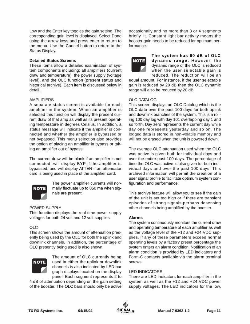
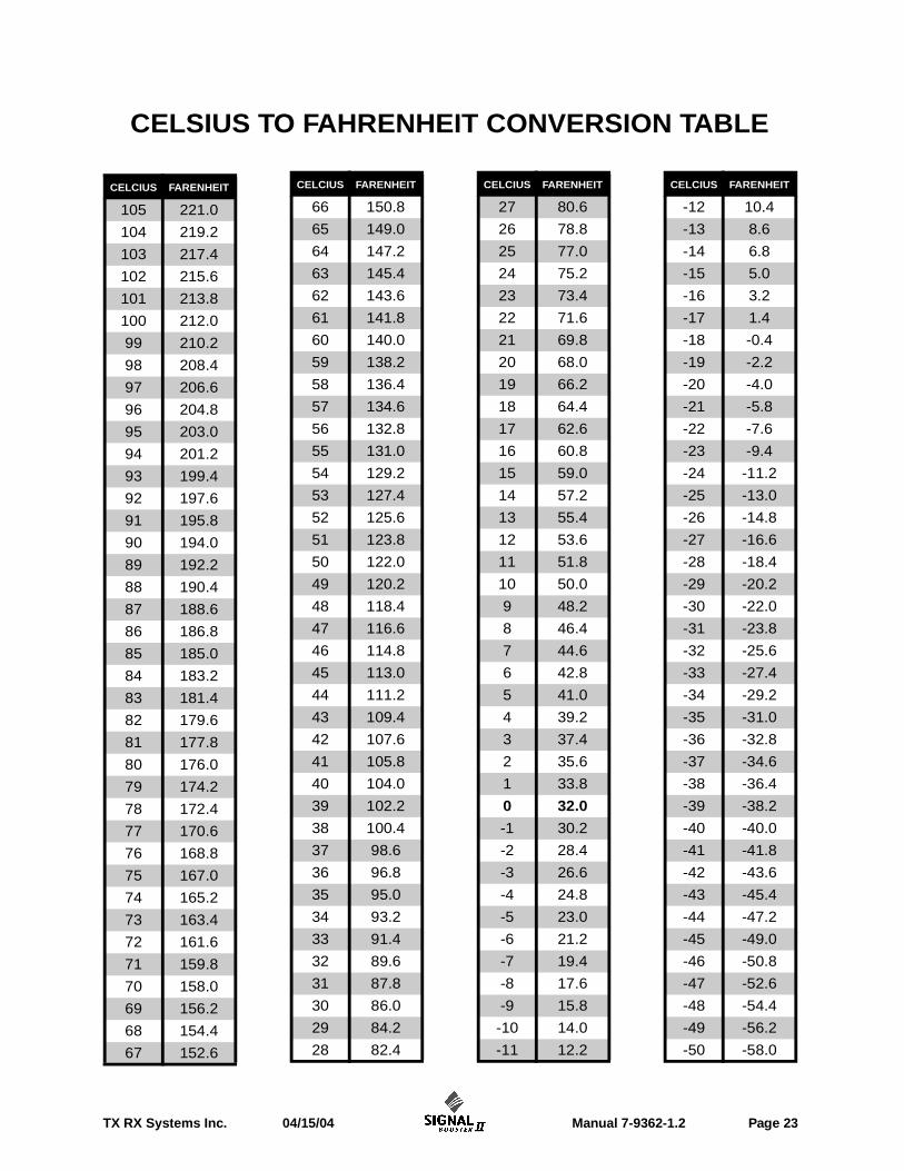
CELSIUS TO FAHRENHEIT CONVERSION TABLE