systematic tripods - cdn.manfrotto.com · ruotare tutti insieme i collari di bloccaggio di ciascuna...
TRANSCRIPT

systematictripods


systematictripods

1
2
Instructions/Istruzioni/Gebrauchsanweisung/Mode d’emploi/Instrucciones
1
1
2
3
45
2

3
5
4
使用说明/사용설명서/使用説明書
6
1
2
3
4
12
X
E
C
D
7
1
2
3

8 9
10
Series 3&4 Series 5
E
F
1
2

English
FIG. 1 – Extending the tripod legsTurn all the twist locks of each leg 1/4 of a turn at the same time, then pull the leg down and tighten the twists individually.
FIG. 2 – Leg angle adjustmentSystematic tripods are fitted with sliding stops, which enable the legs to be individually set at 3 different angles permitting very low angle shooting.
FIG. 3 – Big footWhen using the lowest leg angle in some models, slightly extend the leg tubes to achieve optimum contact with the ground.
FIG. 4 – Interchangeable feetInterchangeable with Gitzo universal accessories such as spiked feet.
FIG. 5 – Attaching AccessoriesThe tripod has one 3/8” female thread which can be used to attach accessories, such as Manfrotto arms that can in turn support lights, monitors, etc.
FIG. 6 – Customize the tripod – remote flat basePress locking lever “C” and at the same time turn it anticlockwise in order to unlock the flat base “D”. Press safety button “E” and remove flat base “D”.

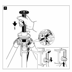
FIG. 7 – Customize the tripod - mount accessoriesOnly for geared column:Ensure winding handle is nearest to the narrow slot on the collar of the tripod.How to lock and unlock the handle.
FIG. 8 – Customize the tripod - removing accessoriesPress safety button “E” in order to remove the accessory.
FIG. 9 – Mounting and removing a camera headSeries 3 and 4Tighten the screw against the base of the head, using the key supplied with the tripod.Series 5 onlyMove the screw “F” against the base of the head using the key supplied with the tripod and then tighten it.
FIG. 10 – MaintenanceThe internal thread of the leg locks can be cleaned and greased to perform optimally. Turn the twist lock until the thread is exposed, and remove any dust or sand with a cloth. Apply a small amount of grease (sold separately: GSGREASE02) onto the thread, and turn the twist lock until it is locked.
In addition to reading these instructions, it is also important to read the general instructions printed on the warranty card packed with your product.

Italiano
FIG. 1 – Estendere le gambe del treppiediRuotare tutti insieme i collari di bloccaggio di ciascuna gamba di 1/4 di giro in senso orario, quindi abbassare le azioni e serrare i singoli collari di bloccaggio.
FIG. 2 – Regolare l’angolazione delle gambeI treppiedi Systematic sono dotati di fermi scorrevoli, per impostare le singole gambe a 3 diverse angolazioni fino alle riprese raso terra.
FIG. 3 – Piedini Quando si utilizza l’angolo gamba più basso, in alcuni modelli, estendere i tubi delle gambe per ottenere un contatto ottimale con il suolo.
FIG. 4 – Piedini intercambiabiliIntercambiabili con gli accessori universali Gitzo come ad esempio i piedini a puntale.
FIG. 5 – Collegamento degli accessoriIl treppiedi è dotato di foro filettato da 3/8” che può essere utilizzato per collegare accessori, ad esempio braccetti Manfrotto che possono sostenere luci, monitor, eccetera.
FIG. 6 – Personalizzazione del treppiedi - rimozione del disco di fissaggioPremere la leva di bloccaggio “C” e contemporaneamente ruotarla in senso antiorario per bloccare il disco di fissaggio “D”. Premere la sicura “E” e rimuovere il disco “D”.

FIG. 7 – Personalizzazione del treppiedi – montaggio di accessori Solo per colonna a cremagliera:Accertarsi che la manovella si trovi il più vicino possibile alla scanalatura sul collare del treppiedi.Bloccaggio e sbloccaggio della manovella.
FIG. 8 – Personalizzazione del treppiedi – rimozione degli accessori Premere la sicura “E” per poter rimuovere l’accessorio.
FIG. 9 - Montaggio e rimozione di una testaSerie 3 e 4Serrare con la chiave in dotazione il grano contro la base della testa.
Solo serie 5Avvitare il grano “F” contro la base della testa tramite la chiave fornita con il treppiedi, stringendola adeguatamente.
FIG. 10 – ManutenzioneLa filettatura interna dei manicotti può essere pulita e lubrificata. Ruotare il manicotto di bloccaggio fino ad esporre la filettatura, e rimuovere la polvere o la sabbia con un panno. Applicare una piccola quantità di grasso (venduto separatamente: GSGREASE02) sulla filettatura e ruotare il manicotto fino a bloccarlo.
Oltre a leggere queste istruzioni, è importante anche consultare le istruzioni generali riportate sulla cartolina di garanzia fornita insieme al prodotto.

Deutsch
ABB. 1 – Stativbeine ausziehenAlle Verschlüsse eines Beines gleichzeitig um eine Viertel-Drehung drehen. Dann das Bein ausziehen und die Verschlüsse in der gewünschten Position festdrehen.
ABB. 2 – Einstellen des Beinwinkels Die Stative Systematic verfügen über eine Anti-Rutsch-Funktion, so dass die Beine einzeln in je drei verschiedenen Winkeln positioniert werde können und damit sehr niedrige Flachwinkel-Aufnahmen möglich sind.
ABB. 3 – Big FootBei Verwendung eines extrem spitzen Winkels, muss das letzte Beinsegment des Stativs ausgezogen sein um einen sicheren Stand gewährleisten zu können.
ABB. 4 – Austauschbare FüßeAuswechselbar mit Gitzo Universal-Zubehör wie z.B. Spikes.
ABB. 5 – Befestigung von ZubehörDas Stativ verfügt über ein 3/8 Zoll Innengewinde, an dem Zubehör, wie z.B. ein Manfrotto Arm befestigt werden kann, um daran Leuchten, Monitore usw. anzubringen.
ABB. 6 – Individuelle Gestaltung des Stativs- Entfernen Sie die flache Platte Drücken Sie auf den Bedienungshebel “C” und drehen Sie ihn gleichzeitig gegen den Uhrzeigersinn, um die flache Platte “D” zu lösen. Drücken Sie den Sicherheitsknopf “E” und entfernen Sie die flache Platte “D”.

ABB. 7 – Individuelle Gestaltung des Stativs – Anbringung von ZubehörNur bei Kurbelsäule:Der Drehgriff muss sich neben dem schmalen Schlitz am Stativkranz befinden. Klemmen und Lösen des Griffs.
ABB. 8 – Individuelle Gestaltung des Stativs- Entfernen Sie das ZubehörDrücken Sie den Sicherheitsknopf “E”, um das Zubehörteil zu entfernen.
ABB. 9 – Befestigen und Demontieren eines KopfesSerie 3 und 4Drehen Sie die Schraube fest gegen die Auflagefläche des Kopfes (mit Hilfe des mitgelieferten Schlüssels).Serien nur 5 Drehen Sie die Schraube “F” gegen die Auflagefläche des Kopfes (mit Hilfe des mitgelieferten Schlüssels) und ziehen Sie sie dann fest.
ABB. 10 – WartungZur einwandfreien Funktion kann das Innengewinde der Beinverschlüsse gereinigt und eingefettet werden. Drehverriegelung so lange drehen, bis das Gewinde freiliegt und eventuell Staub oder Sandkörner mit einem Tuch entfernen. Das Gewinde leicht einfetten (Schmierfett separat erhältlich: GSGREASE02) und dann die Drehverriegelung so lange drehen, bis sie fest verriegelt.
Bitte lesen Sie neben dieser Anleitung auch die allgemeinen Hinweise auf dem Garantieschein, der Ihrem Produkt beiliegt.

Français
FIG. 1 – Ouverture des jambes du trépiedTournez tous les verrouillages de chaque jambe d’un ¼ de tour en même temps, puis tirez la jambe vers le bas et verrouillez les sections individuellement.
FIG. 2 – Ajustement de l’angulation des jambesLe Systematic comporte plusieurs réglages permettant de positionner chaque jambe de manière individuelle sur 3 angles présélectionnés, et ce, pour permettre des photos dans des angles très fermés.
FIG. 3 – Pieds LargesSur certains modèles, lorsque vous utilisez l’angulation de jambe la plus basse, il est conseillé de sortir un petit peu la dernière section de jambe pour permettre un meilleur contact avec le sol.
FIG. 4 – Pieds interchangeablesLes embouts de jambes sont interchangeables avec des accessoires universels Gitzo tels que des pointes.
FIG. 5 – Pas de vis externeLe trépied dispose d’un pas de vis femme 3/8” permettant de visser des accessoires tels que des bras articulés Manfrotto équipés de lampes, d’écran, de flash, de réflecteurs, etc…
FIG. 6 – Personnalisation du trépied - retrait de l’embase platePressez le levier de verrouillage “C” et tournez-le simultanément dans le sens antihoraire afin de déverrouiller l’embase plate “D”. Appuyez sur le bouton de sécurité “E” et retirez l’embase plate “D”.
FIG. 7 – Personnaliser votre trépied - ajouter des accessoiresSeulement pour les colonnes crémaillères:Positionner la poignée au plus près du décrochement du support. Comment bloque et débloquer la poignée.
FIG. 8 – Personnalisation du trépied - retrait des accessoiresPressez le bouton de sécurité “E” afin de libérer l’accessoire.
FIG. 9 – Monter et démonter une rotule photoSeries 3 et 4Resserrer la vis vers la base de la rotule en utilisant la clé fournie.Série 5 uniquementOrientez la vis “F” contre la base de la rotule à l’aide de la clé fournie avec le trépied, puis serrez-la.
FIG. 10 – MaintenanceLe pas de vis interne du verrouillage de section peut être nettoyé et graissé afin d’améliorer son fonctionnement. Dévissez le verrouillage jusqu’à ce que le pas de vis soit totalement visible, puis retirez la poussière ou le sable avec un textile propre. Appliquez ensuite un petite quantité de graisse (vendue séparément: GSGREASE02) sur le pas de vis, puis revissez le verrouillage de section entièrement.
En complément de ces instructions, il est important de prendre connaissance des instructions de la carte de garantie inclue avec votre trépied.

Español
FIG. 1 – Extendiendo las patas del trípodeGire los bloqueos de cada pata 1/4 de vuelta al mismo tiempo, y a continuación estire hacia debajo de la pata y apriete los bloqueos individualmente.
FIG. 2 – Ajuste del ángulo de las patasLos trípodes Systematic vienen equipados con topes de extensión que permiten que las patas se puedan ajustar individualmente a 3 ángulos diferentes lo cual permite hacer tomas a ángulos muy bajos.
FIG. 3 – Big footAl usar el ángulo de las patas más bajo en algunos modelos, extienda ligeramente los tubos de las patas para conseguir un contacto óptimo con el suelo.
FIG. 4 – Pies intercambiables Intercambiables con los accesorios universales Gitzo como los pies con clavo.
FIG. 5 – Montaje de accesorios El trípode posee una rosca hembra de 3/8” que se puede usar para montar accesorios, como un brazo Manfrotto, que es posible utilizar a su vez para soportar luces, monitores, etc.
FIG. 6 – Adaptar el trípode - quite el plato planoPresione sobre la pinza de bloqueo “C” y al mismo tiempo gire en sentido contrario a las agujas del reloj para desbloquear el plato plano “D”. Presione el botón de seguridad “E” y quite la base plana “D”.

FIG. 7 – Personalice el trípode-montaje de accesoriosSolo para la columna con cremallera:Asegúrese de que la manivela esta lo más centrada posible con la ranura del cuello del trípode.Como bloquear y desbloquear la manivela.
FIG. 8 – Adaptar el trípode-quitar accesoriosPulse el botón de seguridad “E” para quitar el accesorio.
FIG. 9 – Montando y quitando la rótulaSeries 3 y 4Apriete el tornillo contra la base de la rótula, usando la llave proporcionada con el trípode.Sólo para Series 5Mueva el tornillo “F” contra la base de la rótula usando la llave proporcionada con el trípode, y luego asegúrelo.
FIG. 10 – Mantenimiento La rosca interna de los bloqueos de las patas se puede limpiar y engrasar para un funcionamiento óptimo. Gire el bloqueo hasta que la rosca quede al descubierto, y elimine la suciedad o arena con un paño. Aplique una pequeña cantidad de grasa (se vende por separado: GSGREASE02) en la rosca, y gire el anillo hasta su bloqueo.
Además de leer este instructivo, es también importante leer las instrucciones generales impresas en la garantía incluida con su producto.

简体中文
图1-伸展脚腿将所有脚管的旋锁同时旋转四分之一圈,然后向下拉伸脚管并将每节脚管的旋锁锁定。
图2-脚管角度调整Systematic三脚架装有滑动挡块,可以分别将脚管固定在3个不同的角度,从而实现极低的角度拍摄。
图3-大脚钉当在一些型号中使用�最低的脚管角度时,请稍微延长脚管来达到和地面最佳接触。
图4-可互换的脚钉可与Gitzo通用配件互换使用,比如钉状脚板
图5-连接配件此款三脚架包含一个3/8英寸的螺口,可以用来连接一些配件,比如通过连接曼富图转接臂来连接灯光类和监视器类产品。
图6-客户自定义组装脚架-移除顶板按下按钮“C”同时逆时针旋松顶板“D”;按下安全钮“E”然后移除顶板“D”
图7-客户自定义组装脚架-安装配件(仅针对齿轮中轴)曲柄对准靠近脚架的轴环然后安装到位。

图8 -客户自定义组装脚架-移除配件请按压安全按钮“E”来移除配件
图9-拆装云台 (系列3和系列4)用三脚架本身携带的工具扳手旋转顶丝让它顶住云台底座
(仅5 系列)用三脚架本身携带的工具扳手移动顶丝“F”来顶住云台底
图10-保养脚管锁的内部螺口 可以清洁并上油从而 保持最佳状态。旋转旋锁部分直到螺纹露出,使用 布清除尘土或沙子。 用少量的油(另售:GSGREASE02)涂在螺纹上,然后旋 上旋锁直到锁定。
除阅读这些说明外,阅读产品保修卡上所印的一般用法说明也很重要。

그림. 1 ‐ 트라이포드 다리 펼치기모든 다리의 트위스트 락을 시계 반대방향으로 1/4씩 동시에 돌린 후, 다리를 밑으로 내리고 다시 트위스트 락을 이용해 고정합니다.
그림. 2 ‐ 다리 각도 조절Systematic 트라이포드에는 3단 각도 조절 기능이 있어 아주 낮은 각도에서의 촬영도 가능합니다
그림. 3 ‐ 빅 풋일부 모델에서 가장 낮은 다리 각도로 설정 시, 다리 튜브를 약간 연장하면 지면과 최적의 상태로 접촉하여 사용할 수 있습니다.
그림. 4 ‐ 교환식 피트스파이크 피트와 같은 짓조 유니버셜 액세서리와 호환 가능합니다.
그림. 5 ‐ 액세서리 장착트라이포드에 포함된 3/8”암나사가 있어 조명, 모니터 등의 액세서리를 맨프로토 암을 이용하여 장착할 수 있습니다.
그림. 6 - 맞춤형 트라이포드 –플랫 베이스 제거고정 레버 “C”를 누르고 동시에 시계 반대 방향으로 돌려서 편평한 플레이트 “D”의 고정을 해제하십시오. 안전 버튼 “E”를 누르고 편평한 베이스 “D”를 빼내십시오.
그림. 7 ‐ 맞춤형 트라이포드 – 액세서리 장착기어 칼럼만 해당:
한국어

와인딩 핸들이 트라이포드의 칼라에 있는 좁은 구멍에 가장 가까워 지도록 주의합니다. 와인딩 핸들을 제자리에 고정하십시오.기어 칼럼만 해당:핸들을 고정하고 해제하는 방법.
그림. 8 - 맞춤형 트라이포드 – 액세서리 제거안전 버튼 “E”를 눌러 액세서리를 제거합니다.
그림. 9 - 카메라 헤드의 장착 및 제거 시리즈 3 & 4트라이포드에 함께 공급되는 키를 사용하여 헤드의 베이스에 나사를 돌리십시오.
시리즈 5만 해당.트라이포드에 함께 공급되는 키를 사용하여 헤드의 베이스에 있는 나사 “F”를 이동한 후 고정하십시오.
그림. 10 ‐ 제품관리레그 락의 내부 나사산은 청소 및 그리스를 칠하여 최적의 작동 컨디션을 유지 할 수 있습니다. 나사산이 보일 때까지 트위스트 락을 돌려 열고 먼지 또는 모래를 천으로 제거합니다. 소량의 그리스를(별도판매: GSGREASE02) 나사산에 칠한 후 트위스트 락이 잠길 때까지 다시 돌려줍니다.
제품 사용 전 이 매뉴얼과 함께 워런티 카드에 작성된 기본 제품 설명서를 함께 읽어 주시기 바랍니다.

日本語図1 - 三脚の伸縮脚のすべてのロックリングを同時に1/4回転緩めて脚を引き出し、次にそれぞれの脚を個別に締めます。
図2 - 開脚角度の調整システマティック三脚はスライド式のピンによって、低いアングルでの撮影にも対応できるよう、3つの開脚角度に設定できます。
図3 - 大型石突最も低いアングルを使用する際に、モデルによっては接地を最適化するために脚チューブを少し伸ばす必要があります。
図4 - 互換石突スパイク石突などジッツオ別売りアクセサリーと交換することができます。
図5 - アクセサリーの接続本三脚は、アクセサリーの接続に使用できる3/8”メスのネジ穴を一つ備えており、例えばManfrottoのアームを接続して照明やモニターなどを支えることができます。
図6 - 三脚のカスタマイズ - トップフラットプレートを外すレバーCを押し込みながら反時計回りに回すことで、トップフラットプレートDのロックを解除します。セーフティーボタンEを押しながらトップフラットプレートDを取り外します。

図7 - 三脚のカスタマイズ - アクセサリーの装着ギア式センターポールのみ:巻き上げ用のハンドルが、三脚のショルダー部分にある狭いスロットに一番近い位置にくるようにしてください。ハンドルのロック・ロック解除の方法
図8 - 三脚のカスタマイズ - アクセサリーの取り外しアクセサリーを取り外すにはセーフティーボタンEを押します。
図9 - 雲台の装着と取り外し シリーズ3、4の場合雲台の装着後、三脚に付属のL字型レンチを使い補助スクリューを雲台底面に締め付けることができます。
シリーズ5の場合雲台の装着後、三脚に付属のL字型レンチを使い補助スクリューFの位置を調整した上で締め付けることができます。
図10 - メンテナンス最適な性能を維持するため、脚ロック内のネジ山を清掃しグリースを塗布することができます。ロックリングをネジ山が露出するまで回し、布でホコリや砂を取り除きます。ネジ山に少量のグリース(別売GSGREASE02)を塗布し、ロックリングを回してロックします。
この使用説明書のほかに、同梱の保証書に記載されている一般情報もご一読ください。

gitzo.com
systematictripods
110039 – 05/2016