systematic probabilistic design methodology for ... improving performance and increasing propulsion...
TRANSCRIPT

Available online at www.sciencedirect.com
+ MODEL
ScienceDirectPublishing Services by Elsevier
International Journal of Naval Architecture and Ocean Engineering xx (2016) 1e10http://www.journals.elsevier.com/international-journal-of-naval-architecture-and-ocean-engineering/
Systematic probabilistic design methodology for simultaneously optimizingthe ship hullepropeller system
Ehsan Esmailian, Hassan Ghassemi*, Hassan Zakerdoost
Department of Maritime Engineering, Amirkabir University of Technology (AUT), Tehran, Iran
Available online ▪ ▪ ▪
Abstract
The proposed design methodology represents a new approach to optimize the propellerehull system simultaneously. In this paper, twoobjective functions are considered, the first objective function is Lifetime Fuel Consumption (LFC) and the other one is cost function includingthrust, torque, open water and skew efficiencies. The variables of the propeller geometries (Z, EAR, P/D and D) and ship hull parameters (L/B,B/T, T and CB) are considered to be optimized with cavitation, blades stress of propeller. The well-known evolutionary algorithm based onNSGA-II is employed to optimize a multi-objective problem, where the main propeller and hull dimensions are considered as design variables.The results are presented for a series 60 ship with B-series propeller. The results showed that the proposed method is an appropriate and effectiveapproach for simultaneously propellerehull system design and is able to minimize both of the objective functions significantly.Copyright © 2016 Society of Naval Architects of Korea. Production and hosting by Elsevier B.V. This is an open access article under the CC BY-NC-ND license (http://creativecommons.org/licenses/by-nc-nd/4.0/).
Keywords: Multi-objective optimization (MOP); Hullepropeller system; Minimizing LFC
1. Introduction
Optimization of ship hullepropeller system is one of themost important aspects of ship design and leads to ship costreduction, improving performance and increasing propulsionsystem lifetime. For a comprehensive and detailed ship hydro-dynamic optimization all objective functions influencing prob-lem solving need to be considered, because it is clear thatconsideration of an objective function without the other onesgives unrealistic and impractical results. In addition to the pa-rameters that usually are considered in the propeller design andoptimization, the skew can be used as other important parame-ters in the propeller design. This parameter affects cavitationand propeller efficiency. Most of the work that has been done inthe design and optimization of hull and propeller problem hasbeen optimized only propeller or hull form with respect to
* Corresponding author.
E-mail address: [email protected] (H. Ghassemi).
Peer review under responsibility of Society of Naval Architects of Korea.
Please cite this article in press as: Esmailian, E., et al., Systematic probabilistic
system, International Journal of Naval Architecture and Ocean Engineering (201
http://dx.doi.org/10.1016/j.ijnaoe.2016.06.007
2092-6782/Copyright © 2016 Society of Naval Architects of Korea. Production and
ND license (http://creativecommons.org/licenses/by-nc-nd/4.0/).
design objectives separately and less work has been carried outin the field of hullepropeller optimization simultaneously.
A method based on linear thin-ship theory to calculate thewave wake generated by a ship presented by Day and Doctors(1997). They used the elemental tent functions as buildingblocks to represent the hull. Dejhalla et al. (2002) proposed agenetic algorithm-based optimization method for an optimi-zation of a ship hull from a hydrodynamic point of view. In theoptimization procedure, the wave resistance has been selectedas an objective function. The genetic algorithm is coupled withthe well-known Dawson panel method for solving the potentialflow around a ship hull. A hull form optimization procedurefor comparing the build cost and LFC developed by Templeand Collette (2012). Grigoropoulos and Chalkias (2010)selected a MOP scheme for the hull form optimization withrespect to its performance in calm and rough water. The nu-merical method proposed by Zakerdoost et al. (2013) foroptimizing hull form in calm water with respect to the totalresistance. The corrected linearized thin-ship theory isemployed to estimate the wave resistance and the EvolutionStrategy (ES) which is a member of the Evolutionary
design methodology for simultaneously optimizing the ship hullepropeller
6), http://dx.doi.org/10.1016/j.ijnaoe.2016.06.007
hosting by Elsevier B.V. This is an open access article under the CC BY-NC-

2 E. Esmailian et al. / International Journal of Naval Architecture and Ocean Engineering xx (2016) 1e10
+ MODEL
Algorithms (EAs) family to minimize the total resistance ofSeries 60 hull form by considering some design constraints. Inaddition, Choi (2015) developed a bell-shaped modificationfunction in order to efficiently modify the hull-form of the shipalong with the minimum wave-making resistance. Park et al.(2015) developed optimization techniques in order to opti-mize the hull form of KSUEZMAX to achieve the minimumvalues of wave-making and viscous pressure resistance co-efficients for the bow and stern at the full-load draft and designspeed conditions.
The ship hull hydrostatics coefficients can be considered asconstraints in optimization process. Yang et al. (2007) describeda preliminary ship design method using deterministic andprobabilistic approach in the process of hull form design withconsidering hull hydrostatics coefficients such as block,midshipcoefficients as constraints in optimization algorithm.
In the field of ship propeller optimization, Benini (2003),Lee and Lin (2004) performed a ship propeller optimizationto maximize the B-series propeller efficiency by utilizing thegenetic algorithm. A numerical optimization technique wasdeveloped by Cho and Lee (1998) to determine the optimumpropeller blade shape for efficiency improvement. A self-twisting propeller was optimized by Pluci�nski et al. (2007),using a genetic algorithm. They considered the orientationangles of the fibers in each layer as the design variables ofefficiency improvement for an optimum design. Chen andShih (2007) designed an optimum propeller by consideringthe vibration and efficiency as objective functions and cavi-tation, strength and power as constraints in B-series propellerusing Genetic Algorithm. A design method for increasingperformance of the marine propellers including the WideChord Tip (WCT) propeller is suggested by Lee et al. (2010).Gaafary et al. (2011) developed a design optimization methodfor B-series marine propellers with a similar objective asprevious work at a single speed. A multi-objective propelleroptimization program was implemented by Xie (2011) tosimultaneously maximize propeller efficiency and thrust co-efficient at a single design speed. The well-known NSGA-IIwas used to approximate Pareto solutions of B-series pro-peller optimization. Kamarlouei et al. (2014) proposed a nu-merical method to evaluate the hydrodynamic performancesincluding minimum cavitation, highest efficiency andacceptable blade strength. The ES technique was used as anoptimization algorithm and main structural parameters asdesign variables to optimize the well-known B-series andDTRC propellers at design speed of typical ships. Mirjaliliet al. (2015) employed Multi-objective Particle Swarm Opti-mization (MOPSO) to maximize efficiency and to minimizecavitation of marine propellers simultaneously. They utilizedshape and number of blades and operating conditions (RPM)as design variables.
In the recent years, some research was done on reducingLFC. Motley et al. (2012) considered the propeller, primemover, and vessel as one integrated system and employed theprobabilistic operational profile of the vessel to minimizeLFC. They evaluated the tradeoffs between different designobjectives and constraints by considering the system
Please cite this article in press as: Esmailian, E., et al., Systematic probabilistic
system, International Journal of Naval Architecture and Ocean Engineering (201
performance characteristics along with probability of occur-rence, and hence allows for global optimization of the pro-peller geometry. Nelson et al. (2013) presents a method tooptimize the propellerehull system simultaneously in order todesign a vessel to have minimal fuel consumption he optimi-zation uses a probabilistic mission profile, propellerehullinteraction, and engine information to determine the coupledcontainer ship and B-series propeller system with minimumfuel cost over its operational life.
This paper concentrates on multi-objective evolutionaryoptimization of the coupled propeller and hull system of a vesselusing the well-known NSGA-II. Two main objectives wereconsidered: total LFC of a vessel and linear combination ofpropeller open water and skew efficiencies, thrust and torque ascost objective function. The ultimate objective is to design ahullepropeller system with minimum LFC and cost that con-siders cavitation and blades stress of propeller as constraints.The main dimensions and ratios of the hull and propeller areconsidered as the design variables in order to achieve a globallyoptimum solution. The coupled series 60 hull form and B-seriesmarine propeller employed as an initial systemmodel. Section 2discusses the problem theory and governing mathematicalformulation for calculating resistance, propeller characteristics,and fuel consumption. In Section 3, an explanation of MOPproblem especially the NSGA-II is presented. The results anddiscussion are then provided in Section 4. Finally, Section 5 isgiven as the conclusions.
2. Methodology and general formulation
2.1. Resistance calculations
When the ship is moving in the calm water, the shear forceand pressure force may be applied against it. The total resis-tance is made up of two components: the viscous resistance,due to moving the ship through a viscous fluid and the waveresistance, due to moving the ship on the surface of the water.The wave resistance resulted from energy dissipation in theformation of waves on the water surface. The total resistancecoefficient is:
CT ¼ CFð1þ kÞ þCw ð1Þwhere CF and Cw are the is the frictional resistance and wave-making resistance coefficients, respectively. k is the formfactor which is determined by
k ¼ 0:6ffiffiffiffiffiffiffiffiffiffiffiffiffiD=rL3
pþ 9D=rL3; ð2Þ
where D is displacement, L is the length of the ship and r is thedensity of water.
The frictional resistance coefficient is calculated byITTC’57 as follows
CF ¼ 0:075
½LogRn � 2�2; ð3Þ
where Rn is the Reynolds number.
design methodology for simultaneously optimizing the ship hullepropeller
6), http://dx.doi.org/10.1016/j.ijnaoe.2016.06.007
3E. Esmailian et al. / International Journal of Naval Architecture and Ocean Engineering xx (2016) 1e10
+ MODEL
When the ship moves in surface of water, waves aregenerated at the fore and stern due to the high pressure. Thesewaves are caused to make resistance, i.e. so called wave-making resistance. There are some theories to determine thewave-making resistance like Michell's theory. Based on thistheory, the equation for the wave resistance is expressed as
8>>>>><>>>>>:
Rw ¼ p
2rU2
Zp=2
�p=2
jAðqÞj2cos3ðqÞdq
Cw ¼ Rw
0:5rU2Sw
ð4Þ
r is the density of water, q is the angle between the direction ofthe moving ship with speed U and that of a propagating waveand A(q) is the amplitude function specific to hull shape,sometimes also called the free wave spectrum and describesthe far field ship waves. More detail of this method can befound in Tuck et al. (2002).
2.2. Propeller calculations
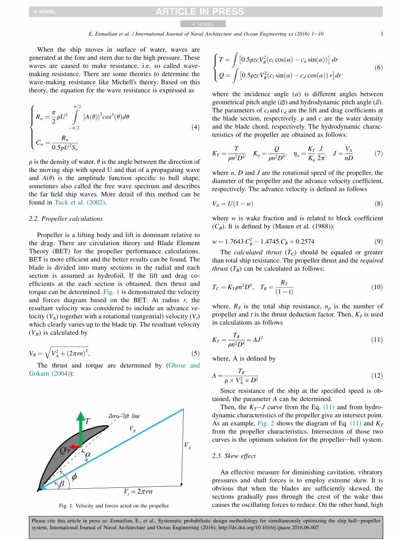
Propeller is a lifting body and lift is dominant relative tothe drag. There are circulation theory and Blade ElementTheory (BET) for the propeller performance calculations.BET is more efficient and the better results can be found. Theblade is divided into many sections in the radial and eachsection is assumed as hydrofoil. If the lift and drag co-efficients at the each section is obtained, then thrust andtorque can be determined. Fig. 1 is demonstrated the velocityand forces diagram based on the BET. At radius r, theresultant velocity was considered to include an advance ve-locity (VA) together with a rotational (tangential) velocity (Vt)which clearly varies up to the blade tip. The resultant velocity(VR) is calculated by
VR ¼ffiffiffiffiffiffiffiffiffiffiffiffiffiffiffiffiffiffiffiffiffiffiffiffiffiffiffiV2
A þ ð2prnÞ2q
; ð5ÞThe thrust and torque are determined by (Ghose and
Gokarn (2004)):
2tV rnπ=
AV
RVT
φ
α/Q r
β
Zero lift line−
Fig. 1. Velocity and forces acted on the propeller.
Please cite this article in press as: Esmailian, E., et al., Systematic probabilistic
system, International Journal of Naval Architecture and Ocean Engineering (201
8><>:
T ¼Z �
0:5rzcV2Rðcl cosðaÞ � cd sinðaÞÞ
�dr
Q¼Z �
0:5rzcV2Rðcl sinðaÞ � cd cosðaÞÞ r
�dr
ð6Þ
where the incidence angle (a) is different angles betweengeometrical pitch angle (∅) and hydrodynamic pitch angle (b).The parameters of cl and cd are the lift and drag coefficients atthe blade section, respectively. r and c are the water densityand the blade chord, respectively. The hydrodynamic charac-teristics of the propeller are obtained as follows:
KT ¼ T
rn2D4; Kq ¼ Q
rn2D5; ho ¼
KT
Kq
J
2p; J ¼ VA
nDð7Þ
where n, D and J are the rotational speed of the propeller, thediameter of the propeller and the advance velocity coefficient,respectively. The advance velocity is defined as follows
VA ¼ Uð1�wÞ ð8Þwhere w is wake fraction and is related to block coefficient(CB). It is defined by (Manen et al. (1988)):
w¼ 1:7643 C2B � 1:4745 CB þ 0:2574 ð9Þ
The calculated thrust (TC) should be equaled or greaterthan total ship resistance. The propeller thrust and the requiredthrust (TR) can be calculated as follows:
TC ¼ KTrn2D4; TR ¼ RT
ð1� tÞ ð10Þ
where, RT is the total ship resistance, np is the number ofpropeller and t is the thrust deduction factor. Then, KT is usedin calculations as follows
KT ¼ TR
rn2D4¼ AJ2 ð11Þ
where, A is defined by
A¼ TR
r�V2A �D2
ð12Þ
Since resistance of the ship at the specified speed is ob-tained, the parameter A can be determined.
Then, the KT�J curve from the Eq. (11) and from hydro-dynamic characteristics of the propeller give an intersect point.As an example, Fig. 2 shows the diagram of Eq. (11) and KT
from the propeller characteristics. Intersection of those twocurves is the optimum solution for the propellerehull system.
2.3. Skew effect
An effective measure for diminishing cavitation, vibratorypressures and shaft forces is to employ extreme skew. It isobvious that when the blades are sufficiently skewed, thesections gradually pass through the crest of the wake thuscauses the oscillating forces to reduce. On the other hand, high
design methodology for simultaneously optimizing the ship hullepropeller
6), http://dx.doi.org/10.1016/j.ijnaoe.2016.06.007

0 0.2 0.4 0.6 0.8 1 1.2 1.4 1.60
0.1
0.2
0.3
0.4
0.5
0.6
0.7
0.8
J
KT, η
o
ηo
KT
AJ2
Fig. 2. Example of the intersection of AJ2 from Eq. (11) and KT propeller characteristics.
4 E. Esmailian et al. / International Journal of Naval Architecture and Ocean Engineering xx (2016) 1e10
+ MODEL
skew angle could also reduce efficiency. The effect of the skewon the propeller efficiency indicates that an approximate for-mula may be obtained for efficiency in terms of the skew angle(Ghassemi, 2009):
hSkew
ho
¼ 0:06687e�0:1148qs þ 0:989e�0:001029qs ð13Þ
where qs is the skew angle in degrees and ho is the open waterefficiency. According to this equation there is an inverserelationship between the skewed propeller efficiency and theskew angle.
2.4. Cavitation constraint
One of the cavitation criteria which may be used to deter-mine the expanded blade area required to avoid cavitation isbased on Keller's criteria (Ghose and Gokarn (2004)). It isgenerally known that cavitation could affect a propeller'sperformance and need to be considered during the designprocess. A simple way to mitigate cavitation is to increase theblade area ratio. Based on the Keller criterion, expanded arearation (AE/A0) is defined as follows:����AE
Ao
����min
¼ ð1:3þ 0:3zÞTðP0 �PVÞD2
þK ð14Þ
where
����AE
Ao
����min
is the minimum blade area ratio, the coefficient
K equals to 0.1 for twin propeller, and 0.2 for single propeller.
2.5. Propeller strength constraint
There are generally five forces acted on the blade, such as;centrifugal force (FC), thrust (T), drag force (means Q/r),forces due to skew and rake (MR and MS), Ghose and Gokarn(2004). Due to the complex shape of the propeller blades, theaccurate calculation of the stress resulting from these forces is
Please cite this article in press as: Esmailian, E., et al., Systematic probabilistic
system, International Journal of Naval Architecture and Ocean Engineering (201
extremely difficult. If blade center of mass locates in radius
r ¼Z R
r0
a rdr=
Z R
r0
rdr, the centrifugal force is calculated by:
FC ¼ mbrð2pnÞ2 ð15Þwhere mb is the blade mass from radius r0 to the blade tip. Sothe moments due to centrifugal force are:
�MR ¼ Fc$zcMs ¼ Fc$yc
ð16Þ
where yc and zc are the space between the centroid of the bladeand centroid of the section. MR and Ms are the moments due torake and skew angels, respectively. So, the stress in bladesection is determined by the following equation, Ghose andGokarn (2004):
S¼ Mx0
Ix0=y0� My0
Iy0�x0
þFC
a0ð17Þ
where
�Mx0 ¼�ðMT þMRÞcos∅� ðMQ �MSÞsin∅Mx0 ¼�ðMT þMRÞcos∅� ðMQ �MSÞsin∅ ð18Þ
where Ix0 and Iy0 are the section modulus's about the xo and yo(axes of the centroid of the section) and a0 is the area of thesection. It is obvious that the cantilever beam theory is asimple method to estimate the maximum tensile or comparisonstress in any blade section. For doing the above-mentionedprocedure, we first of all create a propeller geometry andthen divide the blade sections into 26 stations in chord di-rection and 11 sections in radial, thereafter we do integratingby Simpson methods for calculation of the volume, mo-mentum of inertia and area for the procedure, then calculatethe moments of thrust and torque and at the last step estimatethe stress in blade sections (root, 0.25R and 0.3R). The amount
design methodology for simultaneously optimizing the ship hullepropeller
6), http://dx.doi.org/10.1016/j.ijnaoe.2016.06.007

5E. Esmailian et al. / International Journal of Naval Architecture and Ocean Engineering xx (2016) 1e10
+ MODEL
of stress achieved by this method should be less thanmaximum allowable stress of the propeller material.
2.6. Block coefficient constraint
Fig. 3. SFOC as a function of percentage of load for the L51/60DF engine.
The block coefficient, CB, is defined as the ratio of thevolume of displacement at a particular draft to the volume of arectangular block with the same overall length, breadth anddepth and expressed as
CB ¼ V
LBTð19Þ
where V is displacement volume of the ship in a given draft. Inthe present study, the CB between 0.6 and 0.8 is considered asconstraint in optimization algorithm. This implies that the shipdisplacement is also bonded. However, one can chooseappropriate hydrostatic coefficients for certain applicationconditions and implement it to the proposed optimization.
2.7. Lifetime fuel consumption (LFC)
The specific fuel oil consumption (SFOC) of the engine isprovided by engine manufacturers as a function of engineload. In order to determine the fraction of engine load, thepower requirements must be known. The effective power ofthe vessel PE, relates the vessel resistance and speed by
PE ¼ RTV ð20ÞThe resulting delivered power, PD, required of the pro-
pellers can be calculated using Eq. (21)
PD ¼ PE
QPCð21Þ
where QPC is the quasi-propulsive-coefficient given by theproduct of three efficiencies affecting the hull and thepropeller:
QPC ¼ hHhRRho ð22Þwhere hH is the hull efficiency as shown in Eq. (23), hRR ¼ 1.0is the assumed relative rotative efficiency, and ho is the openwater efficiency as calculated in Eq. (7).
hH ¼ 1� t
1�wð23Þ
In this work, the losses due to shaft and bearing efficienciesare assumed to be negligible. Once the power is calculated theSFOC at any speed can be found based on the percentage ofload. The SFOC for the L51/60DF engine as a function ofengine load taken from marine engine product catalog (2009)and shown in Fig. 3, is used in the current work.
2.8. Probabilistic ship speed profile
Fig. 4. Probabilistic speed profile for a typical ship.
By considering the probabilistic ship speed profile alongwith the ship resistance and SFOC of the prime movers, per-formance comparisons can be made between different
Please cite this article in press as: Esmailian, E., et al., Systematic probabilistic
system, International Journal of Naval Architecture and Ocean Engineering (201
propeller designs that consider the system performance overits design life. In order to avoid minimizing the fuel con-sumption at only a single design speed, a probabilisticapproach was taken in the LFC calculation. This missionprofile is highly dependent on the type of vessel beinganalyzed; for example, a naval combatant may have a highlybimodal distribution while one for a merchant vessel may tendto be unimodal. Using a PDF representing the operationalprofile of the vessel helps to avoid designing a ship that issignificantly sub-optimal at off-design speeds. A probabilitydistribution for a typical ship has been theorized in and isshown in Fig. 4.
Once the resulting PD, SFOC, and mission probabilisticdensity function (PDF ) are known the consumption can befound by integrating across the entire operational range. LFCis estimated by the lifetime hours (Lh) as follows (Nelson et al.(2013)):
LFC ¼Z
P ðVÞ SFOCðVÞPDðVÞdV Lh ð24Þ
design methodology for simultaneously optimizing the ship hullepropeller
6), http://dx.doi.org/10.1016/j.ijnaoe.2016.06.007

6 E. Esmailian et al. / International Journal of Naval Architecture and Ocean Engineering xx (2016) 1e10
+ MODEL
3. Multi-objective optimization
The general mathematical form of a numerical constrainedoptimization problem has been represented here. Design var-iables and constraint conditions are used to characterize theproblem. The role of design variables in hydrodynamic opti-mization problems is controlling the geometry of the hullduring optimization procedure. Constraints are the values bywhich the design variables are restricted and may be separatedin two types, equality and inequality constraints. A functionbeing maximized or minimized by users is known as theobjective function and the value of this function is a criterionto determine the efficiency of design optimization methodol-ogy. If in an optimization problem only one objective functionis used the optimization is known as single objective and iftwo or more objective functions are used the optimization isknown as multi objective. The standard formulation of a MOPproblem mathematically is as follows:
Optimize FðXÞ ¼ ½f1ðXÞ; f2ðXÞ;…; fmðXÞ�T X2<n
FðxÞ ¼ ½f1ðxÞ; f2ðxÞ;…; fmðxÞ�x2Rn
FðxÞ ¼ ½f1ðxÞ; f2ðxÞ; :::; fmðxÞ�x2Rn Subject to some equalityand inequality constraints
hiðXÞ ¼ 0 i¼ 1;2;…;p ð25Þ
gjðXÞ � 0 j¼ 1;2;…;q ð26Þ
where fiðXÞfiðxÞ is the objective function, m is the number ofobjective function, q is the number of equality constraints, p isthe number of inequality constraints andX ¼ ðx1;…; xnÞ2J4ℂ x ¼ ðx1; :::; xnÞ2F4S is a solutionor individual. The set ℂ4ℝnS4Rn defines the search spaceand the set J4ℂ F4S defines a feasible search space.
When we have solved the MOP, we will have found amultitude of solutions. Only a small subset of these solutionswill be of interest. For a solution to be interesting there subsista domination relation between the solution considered andother solutions in the following sense:
We say that a vector U dominates a vector V if U is a leastas good as V for all the objectives, and U is strictly better thanV for at least one objective.
ci2f1;2;…;ng;ui � vi∧d j2f1;2;…;ng; uj � vj
Solutions which dominate the others but do not dominatethemselves are called Pareto set (or non-dominated solutions)and their corresponding objective functions are called Paretofront.
3.1. Non-dominated sorting genetic algorithm-II (NSGA-II)
NSGA-II is a well-known fast and elitist multi-objectivegenetic algorithm that is used in this paper. The non-dominated sorting method is an important characteristic ofNSGA-II. The following are the steps of the NSGA-II (Deb,2002);
Please cite this article in press as: Esmailian, E., et al., Systematic probabilistic
system, International Journal of Naval Architecture and Ocean Engineering (201
1. Initialize the population2. While the termination criterion is not met repeat the
following:a. Evaluate each solution in the population by
computing objective function values.b. Rank the solutions in the population using non-
dominated sorting.c. Perform selection using the crowded binary tourna-
ment selection operator.d. Perform cross over and mutation (as in conventional
genetic algorithm) to generate the offspringpopulation.
e. Combine the parent and child populations.f. Replace the parent population by the best members(selected using non-dominated sorting and thecrowded comparison operator) of the combinedpopulation.
3. Output the first non-dominated front of the population
3.2. Program implementation
Fig. 5 demonstrates how the aforementioned methods andtechniques are utilized to optimize the hullepropeller system.First, by using initial values and employing the Michell'stheory and ITTC-57 correction line formula the total resis-tance is calculated. The operating advance coefficient (andhence the required propeller rpm), the propeller performancesand skew efficiency at this design advance coefficient are thenobtained based on the known values of RT from previous stepand the design variables and using BET.
If the physical constraints, the cavitation, propeller stressand block coefficient, are not satisfied, two penalty functionswill be considered and added to the objective functionsvalues. After that to consider the lifetime of the vessel in theoptimization process the LFC and Cost functions, two life-time objective functions used in this work, are computed bytaking into account the probabilistic mission profile of thevessel. The Cost function is a linear combination of propelleropen water and skew efficiencies, thrust and torque loads asalready mentioned. Finally the algorithm is repeated and oncethe algorithm reaches its maximum generation, the Paretofront is drawn and the final optimal solution is selected fromit based on owner's or designer's conditions. Before applyingthe NSGA-II Algorithm we need to choice appropriateparameter settings. In this study the parameters is presentedin Table 1.
The design variables and the objective functions vectorsused in the optimization process are as follows as shown inFig. 5. The lower and upper limits of the vector are depicted inTable 2.
X ¼ ½L=B;B=T ;T ;EAR;Z;D;P=D;J;Skew;S�
FðXÞ ¼ ½LFCðXÞ; CostðXÞ�Weight amounts of thrust, torque, open water and skew
efficiencies are given in Table 3. It is assumed that the skew
design methodology for simultaneously optimizing the ship hullepropeller
6), http://dx.doi.org/10.1016/j.ijnaoe.2016.06.007

Fig. 5. Flowchart of the hullepropeller optimization process.
Table 1
Parameter settings of NSGA-II Algorithm.
Value Type of parameter
550 Max generation
8 Population size
30% Rate of mutation
Random Mutation type
70% Rate of recombination
7E. Esmailian et al. / International Journal of Naval Architecture and Ocean Engineering xx (2016) 1e10
+ MODEL
efficiency do not play a significant role and has lower weightin comparison with the other parameters in cost function.
4. Results and discussion
The results and analysis of the optimization run using thepreviously defined objective and constraint functions are pre-sented in this section. Calculations were made on a windows-based personal computer having 2.4-GHz CPUs. The requiredtime for running this program code is about 5 h.
As a result of the evolutionary process, the NSGA-IIpromotes spreading of the individuals along the Paretofront, as shown in Fig. 6. The end part of generations is
Please cite this article in press as: Esmailian, E., et al., Systematic probabilistic
system, International Journal of Naval Architecture and Ocean Engineering (201
utilized by the algorithm to distribute the solutions as uni-formly as possible on the front. This is a consequence ofmaintaining of a diverse set of solutions in the non-dominatedfront by using the NSGA-II. This uniform distribution is more
design methodology for simultaneously optimizing the ship hullepropeller
6), http://dx.doi.org/10.1016/j.ijnaoe.2016.06.007

Table 2
Limits of the design variables vector.
Upper limit Lower limit Design variable
6 3 Number of blades (Z)
30 0 Skew angle [�]39 e Maximum allowable
stress (SAllow) [MPa]
1.5 0.4 Pitch ratio (P/D)
1.4 0.5 Propeller advance coefficient (J )
6 3 Propeller diameter (D) [m]
1.05 0.55 Expanded area ratio (EAR)
12 8.8 Draft (T) [m]
3.6 1.2 Breadth to draft ratio (B/T)
8 5 Length to breadth ratio (L/B)
0.8 0.6 Block coefficient (CB)
Table 3
The performance weights in cost function.
Skew efficiency Efficiency Torque Thrust Performance
0.1 0.3 0.3 0.3 Weight
Fig. 6. The Pareto front, utopia and compromise solutions.
8 E. Esmailian et al. / International Journal of Naval Architecture and Ocean Engineering xx (2016) 1e10
+ MODEL
due to the selection mechanism of the best solution in theoptimization algorithm. Choosing the preferred solutionamong the optimal solutions (Pareto front) depends on theowner's or designer's conditions and a decision making skill is
Table 4
The initial and optimal solutions (Pareto front).
Parameter Initial value Opt. value 1 Opt. value 2 Opt. value
L/B 5.2 7.81 7.70 6.42
B/T 1.57 2.28 1.45 3.18
T 10.59 9.29 10.95 11.99
EAR 0.97 0.69 0.85 0.71
Z 6.00 3.00 5.00 4.00
D 5.78 4.97 4.68 5.05pD
1.28 0.50 0.65 0.76
J 0.74 1.15 0.50 1.07
Skew 21.68 10.83 15.81 17.76
LFC 7.42E11 7.25Eþ10 7.25Eþ10 7.2Eþ10
Cost 4.99E5 7.36 7.36 7.72
Please cite this article in press as: Esmailian, E., et al., Systematic probabilistic
system, International Journal of Naval Architecture and Ocean Engineering (201
applied to find it. We select the solution that is as close aspossible to utopia point and is called compromise solution asshown in Fig. 6. First the objective functions are normalizedand the distance between each solution on the Pareto frontand the utopia point is measured. Eventually the solutionhaving minimum distance is chosen as the compromisesolution.
The results confirm that there is an apparent conflict be-tween the LFC and cost objective function, that is, increasingin LFC will lead to decreasing in Cost and vice versa.
The initial and optimal (Pareto front) solutions are reportedin Table 4. The compromise point in Fig. 6 is equivalent tooptimal value 5 in Table 4. As can be seen in this table thedesign variables of the ship hull i.e. L/B, B/T and T are thesame for all optimal solutions and this indicates that differenceof the optimal points is more influenced by the propellercharacteristics.
It should be noted in order to assurance the optimizationconstraints will be satisfied, the large penalty function hasbeen considered and therefore the large initial cost value isshown in Table 4.
Increasing the pitch ratio leads to increasing the propellerthrust and torque and thus the probability of the occurrence ofthe cavitation phenomenon increases. Therefore, this amountshould be optimized so that produces enough thrust while pre-venting the cavitation phenomenon. Considering that alloptimal solutions satisfy the cavitation constraint, the pitch ratiovalue 0.94 can be an appropriate value for the selected propeller.
It is known that skew causes to eliminate dynamic load on theblade, reduce the fatigue and improve the propeller timeendurance (lifetime). So, the selection of optimum value for theskew angle is an important issue. The optimal values of the skewangle for the Pareto front change in the small interval,6.76e28.33, which are reasonable values for the B-seriespropeller.
Fig. 7 shows comparison of the total resistance for theoptimal hull and the initial hull within in terms of the shipspeed. It can be seen that the total resistance for the optimalhull is decreased at all speed range significantly. Therefore, theoptimized hull can conduct effectively in its lifetime. Table 4confirms that however the optimal values of the parametersvary slightly relative to each other; they have considerablechange relative to the corresponding initial values.
3 Opt. value 4 Opt. value 5 Opt. value 6 Opt. value 7
5.26 7.18 5.19 5.37
3.30 2.84 3.10 1.62
8.87 9.83 10.23 10.92
0.63 0.96 0.66 0.60
6.00 6.00 5.00 5.00
5.07 4.30 5.17 4.37
0.94 0.55 0.62 0.96
1.28 0.92 1.29 0.65
8.38 28.33 12.63 6.76
7.23Eþ10 7.23Eþ10 7.2Eþ10 7.23Eþ10
7.56 7.44 7.72 7.52
design methodology for simultaneously optimizing the ship hullepropeller
6), http://dx.doi.org/10.1016/j.ijnaoe.2016.06.007
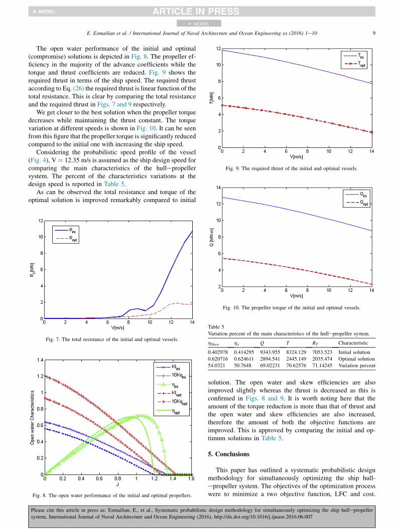
Fig. 9. The required thrust of the initial and optimal vessels.
9E. Esmailian et al. / International Journal of Naval Architecture and Ocean Engineering xx (2016) 1e10
+ MODEL
The open water performance of the initial and optimal(compromise) solutions is depicted in Fig. 8. The propeller ef-ficiency in the majority of the advance coefficients while thetorque and thrust coefficients are reduced. Fig. 9 shows therequired thrust in terms of the ship speed. The required thrustaccording to Eq. (26) the required thrust is linear function of thetotal resistance. This is clear by comparing the total resistanceand the required thrust in Figs. 7 and 9 respectively.
We get closer to the best solution when the propeller torquedecreases while maintaining the thrust constant. The torquevariation at different speeds is shown in Fig. 10. It can be seenfrom this figure that the propeller torque is significantly reducedcompared to the initial one with increasing the ship speed.
Considering the probabilistic speed profile of the vessel(Fig. 4), V ¼ 12.35 m/s is assumed as the ship design speed forcomparing the main characteristics of the hullepropellersystem. The percent of the characteristics variations at thedesign speed is reported in Table 5.
As can be observed the total resistance and torque of theoptimal solution is improved remarkably compared to initial
Fig. 7. The total resistance of the initial and optimal vessels.
Fig. 8. The open water performance of the initial and optimal propellers.
Fig. 10. The propeller torque of the initial and optimal vessels.
Table 5
Variation percent of the main characteristics of the hullepropeller system.
hSkew ho Q T RT Characteristic
0.402978 0.414295 9343.955 8324.129 7053.523 Initial solution
0.620716 0.624611 2894.541 2445.149 2035.474 Optimal solution
54.0321 50.7648 69.02231 70.62576 71.14245 Variation percent
Please cite this article in press as: Esmailian, E., et al., Systematic probabilistic
system, International Journal of Naval Architecture and Ocean Engineering (201
solution. The open water and skew efficiencies are alsoimproved slightly whereas the thrust is decreased as this isconfirmed in Figs. 8 and 9. It is worth noting here that theamount of the torque reduction is more than that of thrust andthe open water and skew efficiencies are also increased,therefore the amount of both the objective functions areimproved. This is approved by comparing the initial and op-timum solutions in Table 5.
5. Conclusions
This paper has outlined a systematic probabilistic designmethodology for simultaneously optimizing the ship hull-epropeller system. The objectives of the optimization processwere to minimize a two objective function, LFC and cost.
design methodology for simultaneously optimizing the ship hullepropeller
6), http://dx.doi.org/10.1016/j.ijnaoe.2016.06.007

10 E. Esmailian et al. / International Journal of Naval Architecture and Ocean Engineering xx (2016) 1e10
+ MODEL
NSGA-II is first employed to estimate the Pareto front, andthen a decision making skill is applied to find the best solutionamong them. It is apparent from this study that the techniqueproposed here has high capability and is appropriate for pre-liminary design of ship hull and propeller. Based on the nu-merical results, following conclusions can be drawn:
� From the results, it is concluded that the main character-istics of the integrated hull- The results have demonstratedthat NSGA-II, which can find Pareto front solutions withgood diversity and convergence, is an efficient approach tosolve the multi-objective optimization problems such asthe design problem of the ship-propeller propeller systemhave been improved except the required thrust and ingeneral the LFC and cost functions have been minimizedsignificantly.
� The effect of skew angle is important on the hydrody-namic characteristics and is a new operating parameter toestimate propeller efficiency in this investigation.
� One of the key factors for approximating total ship cost isthe LFC, thus improving the propeller and a hull perfor-mance which minimizes the LFC function could have asignificant impact on reducing the lifetime cost of thevessel.
References
Benini, E., 2003. Multiobjective design optimization of B-screw series pro-
pellers using evolutionary algorithms. Mar. Technol. 40 (4), 229e238.Chen, J.-H., Shih, Y.-S., 2007. Basic design of a series propeller with vibration
consideration by genetic algorithm. J. Mar. Sci. Technol. 12 (3), 119e129.
Cho, J., Lee, S.-C., 1998. Propeller blade shape optimization for efficiency
improvement. Comput. Fluids 27 (3), 407e419.Choi, H.J., 2015. Hull-form optimization of a container ship based on bell-
shaped modification function. Int. J. Nav. Archit. Ocean. Eng. 7 (3),
478e489.Day, A.H., Doctors, L.J., 1997. Resistance optimization of displacement
vessels on the basis of principal parameters. J. Ship Res. 41 (4),
249e259.
Deb, K., 2002. A fast and elitist multiobjective genetic algorithm: NSGA-II.
IEEE Trans. Evol. Comput. 6 (2), 182e197.
Please cite this article in press as: Esmailian, E., et al., Systematic probabilistic
system, International Journal of Naval Architecture and Ocean Engineering (201
Dejhalla, R., Mr�sa, Z., Vukovi�c, S., 2002. A genetic algorithm approach to the
problem of minimum ship wave resistance. Mar. Technol. 39 (3),
187e195.
Gaafary, M., El-Kilani, H., Moustafa, M., 2011. Optimum design of B-series
marine propellers. Alex. Eng. J. 50 (1), 13e18.Ghassemi, H., 2009. The effect of wake flow and skew angle on the ship
propeller performance. Sci. Iran. 16 (2), 149e158.
Ghose, J.P., Gokarn, R.P., 2004. Basic Ship Propulsion. Allied Publishers.
Grigoropoulos, G.J., Chalkias, D.S., 2010. Hull-form optimization in calm and
rough water. Comput.Aided Des. 42 (11), 977e984.
Kamarlouei, M., Ghassemi, H., Aslansefat, Nematy, D., 2014. Multi-objective
evolutionary optimization technique applied to propeller design. Acta
Polytech. Hung. 11 (9).
Lee, C.-S., Choi, Y.-D., Ahn, B.-K., Shin, M.-S., Jang, H.-G., 2010. Perfor-
mance optimization of marine propellers. Int. J. Nav. Archit. Ocean. Eng. 2
(4), 211e216.Lee, Y.-J., Lin, C.-C., 2004. Optimized design of composite propeller. Mech.
Adv. Mater. Struct. 11 (1), 17e30.
Mirjalili, S., Lewis, A., Mirjalili, S.A.M., 2015. Multi-objective optimisation
of marine propellers. Procedia Comput. Sci. 51, 2247e2256.
Motley, M.R., Nelson, M., Young, Y.L., 2012. Integrated probabilistic design
of marine propulsors to minimize lifetime fuel consumption. Ocean. Eng.
45, 1e8.Nelson, M., Temple, D.W., Hwang, J.T., Young, Y.L., Martines, J.R.R.A.,
Collette, M., 2013. Simultaneous optimization of propellerehull systems
to minimize lifetime fuel consumption. Appl. Ocean Res. 43, 46e52.
Park, H., Choi, J.E., Chun, H.H., 2015. Hull-form optimization of KSUEZ-
MAX to enhance resistance performance. Int. J. Nav. Archit. Ocean. Eng. 7
(1), 100e114.
Pluci�nski, M.M., Young, Y.L., Liu, Z., 2007. Optimization of a self-twisting
composite marine propeller using genetic algorithms. In: 16th Interna-
tional Conference on Composite Materials, Kyoto, Japan.
Temple, D., Collette, M., 2012. Multi-objective hull form optimization to
compare build cost and lifetime fuel consumption. In: International Ma-
rine Design Conference, IMDC, Glasgow, Scotland, 11-14 06, II,
pp. 391e403.
Tuck, E., Scullen, D., Lazauskas, L., 2002. Wave patterns and minimum wave
resistance for high-speed vessels. In: 24th Symposium on Naval Hydro-
dynamics, Fukuoka, Japan.
Xie, G., 2011. Optimal preliminary propeller design based on multi-objective
optimization approach. Procedia Eng. 16, 278e283.
Yang, Y.S., Park, C.K., Lee, K.H., Suh, J.C., 2007. A study on the preliminary
ship design method using deterministic approach and probabilistic
approach including hull form. Struct. Multidiscip. Optim. 33 (6),
529e539.
Zakerdoost, H., Ghassemi, H., Ghiasi, M., 2013. Ship hull form optimization
by evolutionary algorithm in order to diminish the resistance. J. Mar. Sci.
Appl. 12 (2), 170e179.
design methodology for simultaneously optimizing the ship hullepropeller
6), http://dx.doi.org/10.1016/j.ijnaoe.2016.06.007