systematic derivation of functional safety requirements ... · pdf filesystematic derivation...
TRANSCRIPT

Systematic Derivation of Functional SafetyRequirements for Automotive Systems
Kristian Beckers1, Isabelle Cote2, Thomas Frese3, Denis Hatebur1,2, andMaritta Heisel1∗
1 Universitat Duisburg-Essen, Germany, Fakultat fur Ingenieurwissenschaften, email:{kristian.beckers,maritta.heisel}@uni-due.de
2 Institut fur technische Systeme GmbH, Germany, email:{i.cote,d.hatebur}@itesys.de
3 Ford Werke GmbH, email: [email protected]
Abstract. The released ISO 26262 standard for automotive systemsrequires breaking down safety goals from the hazard analysis and riskassessment into functional safety requirements in the functional safetyconcept. It has to be justified that the defined functional safety require-ments are suitable to achieve the stated safety goals. In this paper, wepresent a systematic, structured and model-based method to define func-tional safety requirements using a given set of safety goals. The ratio-nale for safety goal achievement, the relevant attributes of the functionalsafety requirements, and their relationships are represented by a UMLnotation extended with stereotypes. The UML model enables a rigor-ous validation of several constraints expressed in OCL. We illustrate ourmethod using an example electronic steering column lock system.
1 Introduction
The automotive standard for road vehicles ISO 26262 [1], released in 2011, is seenas an automotive industry standard for developing functional safety systems, be-cause it offers the ability to achieve a consistent functional safety process. Itsscope covers electronic and electric (E/E) systems for vehicles with a max grossweight up to 3500 kg. Since ISO 26262 is a risk-based functional safety standardaddressing malfunctions, its process involves a hazard analysis to determine thenecessary risk reduction to achieve an acceptable level of risk. In [2], we describedhow to define safety goals with an automotive safety integrity level (ASIL) thatdescribes this necessary risk reduction. According to ISO 26262, the next stepis to break down these safety goals into functional safety requirements. It hasto be justified that the defined functional safety requirements are suitable toachieve the stated safety goals. Functional safety concepts in practice are cur-rently document-based using text processing and drawing tools such as Microsoft
∗Part of this work is funded by the German Research Foundation (DFG) under grantnumber HE3322/4-2 and the EU project Network of Excellence on Engineering SecureFuture Internet Software Services and Systems (NESSoS, ICT-2009.1.4 TrustworthyICT, Grant No. 256980).

Word and Visio. In this paper, we present a systematic, structured and model-based method to define functional safety requirements using a given set of safetygoals. The rationale for safety goal achievement, the relevant attributes of thefunctional safety requirements, and their relationships are represented by usingUML notation [3] extended by stereotypes. The UML models enable a rigorousvalidation of several constraints expressed in the Object Constraint Language(OCL) [4]. Our method is applied to an electronic steering column lock system,serving as illustrative example.
For the break-down of safety goals into functional safety requirements, theISO 26262 gives no dedicated guidance. It only defines requirements on thecontent of the documentation. Performing such a break-down is a challengingtask because:– A sound rationale has to be provided.– Assumptions have to be handled appropriately.– For the functional safety requirements, the necessary attributes depending
on the requirement type have to be defined.– The functional safety requirements have to be implementable.– Review activities have to be performed.
In this paper, we propose a structured method based on UML environment mod-els supported by a tool. We assume that an item definition, hazard analysis, riskassessment and safety goals according to ISO 26262 are given (see e.g. [2]). Inthis paper, we focus on the next step: the creation of a functional safety concept(FSC) in which we show how the functional safety requirements are systemati-cally derived. In the FSC, additionally, requirements may be decomposed in orderto lower the ASIL. Furthermore, the functional safety requirements are allocatedto elements of a preliminary architecture. These aspects are appropriately de-scribed in the ISO 26262 and need no further explanation and improvementand are, therefore, not part of this paper. The contribution of our paper can besummarized as follows:
Rationales are given that show that all safety goals are fulfilled if the require-ments are realized, as required by ISO 26262. This will be achieved by usingthe goal structuring notation with patterns for several solution strategies.
Assumptions are generated based on different sources. It has to be ensuredthat these assumptions are valid. This is ensured by generating require-ments with corresponding descriptions of validation and verification (V&V)activities for them.
Only relevant attributes are described by the developer. This is achieved byclassifying the requirements into different categories and by defining, whichattributes are required, which are optional, and which should be left outaccording to the category.
UML profile for expressing all elements of a functional safety concept iscreated in compliance with ISO 26262 making it possible to apply all alreadymentioned aspects. The profile also provides the basis for validation checkswritten in OCL.
OCL validation checks concerning consistency and correctness of the func-tional safety concept are set up. Thus, we provide a computer-aided tech-nique to discover errors in the hazard analysis caused by finding inconsis-tencies or errors in one or more of the UML models.
2

Functional safety concept document can be generated by the tool, basedon the information contained in our UML models. The resulting documen-tation can then be used for reviewing purposes.
Our paper is organized as follows. The goal structuring notation is introducedin Sect. 2.1. In Sect. 2.2, we give a brief overview of ISO 26262. Our method ispresented in Sect. 3. This section also describes our UML profile, which is usedto express the functional safety concept. Based on this profile, we define thevalidation conditions. The tool support is outlined in Sect. 4. We introduce theillustrative example of an electronic steering column lock system as case studyin Sect. 5. Section 6 presents related work, while Sect. 7 concludes the paper andgives directions for future work.
2 Background
This section introduces the notation used to derive and justify functional safetyrequirements (Sect. 2.1. It also provides a short reference to the standard usedin this paper (Sect. 2.2).
2.1 Goal Structuring Notation
The Goal Structuring Notation (GSN)[5] - a graphical argumentation notation -explicitly represents the individual elements of any safety argument (goal, strat-egy, assumption, justification, context, and requirements) and – perhaps moresignificantly – the relationships that exist between these elements, i.e., how indi-vidual requirements are supported by specific strategies, and the assumed con-text that is defined for the argument.
In the Functional Safety Concept, GSN is used to provide an argument forFunctional Safety Requirements starting from Safety Goals, thus also providingthe means to check the consistency between Safety Goals and Functional SafetyRequirements. In Fig. 1, the GSN elements and their usage for Functional Safetyare depicted [6, 7]. The “claim” of the argumentation is the (Safety) Goal (e.g.SG03). The Strategy expresses the rationale how the goal is addressed by sub-goals or functional safety requirements (e.g. ESCL-F-S-Req 03). Sub-Goals rep-resent an intermediate step between safety goals and functional safety require-ments. Relationships between these elements are expressed with supported by,
Fig. 1. GSN Notation Overview
3

ext
ern
al in
pu
tm
eth
odin
pu
t/ou
tpu
t
3. Check for Completness of Requirements
5. Allocate requirements to the preliminary
architecture
6. Perform safety analysis, simulation, and
test
4. ASIL Decomposition
1. Break down safety
goals
2. Specify all applicable
attributes of the requirements
Goal-Structure
Safety Goals
UML4PF Profile including GSN extensions
Strategy Patterns
RefinedSafety Requirements
Preliminary Architecture
Safety Analysis, Simulation, andTest
Allocation
7. Verification and Integrity
Checks
Review Results
Fig. 2. Method for Functional Safety Concept Creation
optional and alternatives with the element for M out of N. For a goal, strategies,subgoals, functional safety requirements, Context, Justifications, and Assump-tions can be defined. These relationships are annotated using in context of.
Goal structures might reach a size that is hard to fit on a page. To split such abig structure into several smaller ones, we introduced two additional referenceelements (see “W&RC3” in Fig. 1).
2.2 ISO 26262
ISO 26262 is a risk-based functional safety standard intended to be appliedto safety-related systems that include one or more E/E systems and that areinstalled in series productions of passenger cars It addresses possible hazardscaused by malfunctions of E/E safety-related systems, including the interactionof these systems.
ISO 26262 was derived from the generic functional safety standard ISO/IEC61508 [8]. It is aligned with the automotive safety life-cycle including specifica-tion, design, implementation, integration, verification, validation, configuration,production, operation, service, decommissioning, and management. ISO 26262provides an automotive-specific risk-based approach for determining risk classesthat describe the necessary risk reduction for achieving an acceptable residualrisk, called automotive safety integrity level (ASIL).
The possible ASILs are QM, ASIL A, ASIL B, ASIL C, and ASIL D. TheASIL requiring the highest risk reduction is ASIL D. For functions with ASILA, ASIL B, or ASIL C, fewer requirements on the development processes, safetymechanisms, and evidences are required. In case of a QM rating, the normalquality measures applied in the automotive industry are sufficient.
3 Method for Functional Safety Concept
We propose a method to create a functional safety concept according to ISO 26262.The aim of the analysis is to break down the generic safety goals into functionalsafety requirements and allocate them to logical elements of a preliminary ar-chitecture. Figure 2 depicts an overview of our method consisting of seven steps.Each step is described in the subsequent paragraphs.
4

Fig. 3. UML Profile for Goal Structuring Notation Elements
1. Break-down safety goals into functional safety requirementsISO 26262 requires that the safety goals from the hazard analysis [2] are broken-
down into functional safety requirements. This can be documented using the goalstructuring notation (see Sect. 2.1). Figure 3 shows the UML profile for the ele-ments of a goal structure. Throughout several projects, it was possible to detectrecurring patterns while setting up goal structures. These patterns were trans-formed into so-called strategy patterns. One of these patterns being used in Fordprojects, is the use of independent sources to obtain certain information, e.g., thevehicle speed and the ignition status can be used for detecting standstill. Furtherpatterns can be found in [9]. The stereotypes for (�SafetyGoal�, �SubGoal�,as well as sub-types of �FunctionalSafetyRequirement�) including their respec-tive attributes, are shown in Fig. 4. These elements are explained in more detailin Step 2 of our method. The goal structures document the justification that thefunctional safety requirements are suitable to address the safety goals obtainedfrom the hazard analysis and risk assessment. They include all assumptions nec-essary to address the respective safety goal. For better readability, the names ofthe elements in the goal structure (i.e. safety goal, subgoal, strategy, assumption,context, justification, functional safety requirement or its sub-types) are unique.To verify that, the condition 1M01UE1 has been formulated (see Tab. 4). Ac-cording to [6] and [7], not all elements can be connected with each other. Therelationships between the different elements are realized as follows:
– classes with the stereotypes �SafetyGoal�, �SubGoal�, or �Strategy�are connected to classes with stereotypes �SubGoal�, �Strategy�, or sub-types of �FunctionalSafetyRequirement� by dependencies starting from theformer and pointing to the latter. This is checked by condition 1M02DG.Furthermore, we check that two strategies are not directly connected toeach other (see Tab. 4, 1M03DS).
– �Justification�, �Context�, and �Assumption� are connected to�SafetyGoal�, �SubGoal�, �Strategy� or sub-types of �Functional-SafetyRequirement� by dependencies starting from the former pointing tothe latter. This is verified by condition 1M04DC.2
1The first number refers to the step in the procedure, C is for consistency checks,M is for checks considering correct modeling, G is for generation, the next number isthe number of the check within the step, and the last characters are an abbreviationof the description.
2In the following, references to validation conditions are given in parentheses.
5

Fig. 4. Elements for Safety Requirements
2. Specify all applicable attributes of the requirementsThe requirements developed in Step 1 must to be refined. We support Step
2 with a UML profile that can be used to express the different requirementtypes. Figure 4 shows the part of our profile that is used to express the differentrequirement types. A class with the stereotype �Requirement� is used to de-scribe the requirements in general. Safety requirements (�SafetyRequirement�)are – according to ISO 26262 – special requirements with additional attributesfor ASIL and safe states. Safety Goals (�SafetyGoal�) are top-level safety re-quirements. A �SubGoal� (not being defined in the ISO 26262) is used ingoal structures to structure the argumentation. Functional safety requirements(�FunctionalSafetyRequirement�) are special safety requirements. They de-scribe the functionalities to achieve the safety goals from a functional perspec-tive without any technical details, such as CAN messages. Each functional safetyrequirement addresses a set of safety goals (sg), is valid for a given set of op-erating modes (omM) and should have a purpose (purpose) that may be simi-lar to the strategy or subgoal above. To define functional safety requirementsthat can be verified, e.g., by testing, the method for verification (vVMethod)and the acceptance criteria (vVAcceptanceCriteria) should be defined. The sub-goals or the strategies being supported by the functional safety requirementmust be documented. It is important that operating mode, purpose, text, vali-dation and verification method, and acceptance criteria are set for all functionalsafety requirements (see Tab. 4, 2M01RA). The attributes strategy or subGoal ofa �FunctionalSafetyRequirement� can be automatically set based on the infor-mation in the goal structure by following the dependencies with the stereotypes�supportedBy�, �alternativelySupportedBy� and �optionallySupportedBy�(see Tab. 4, 2M02SG and 2M03SS).
Based on our experience it is helpful to structure the functional safety re-quirements according to the following categories:– general requirements,– safety-related function requirements,– emergency operation requirements,– fault reaction: user information requirements,– fault reaction: recovery requirements, and– decomposition requirements.
6

General requirements (�GeneralRequirement�) could be generic require-ments to electronic or electric elements, requirements to elements of other tech-nologies, external measures, or other requirements, e.g., requirements addressingassumptions. For general requirements, it should be possible to define a faulttolerant time (ftt) and the emergency operation interval (emergencyOpInterval).The fault tolerant time defines the period of time between the occurrence of afunctional fault and this fault actually becoming dangerous (if it remains un-detected). If a safe state cannot be reached by a transition within an accept-able time interval, an emergency operation time interval and a reference to theemergency operation requirement shall be specified. We define general safetyrequirements for all assumptions to ensure that they are validated or verified.Assumptions are defined– in the hazard analysis to focus the scope of the analysis to a dedicated vehicle
line,– in the risk assessment on actions of driver or other persons involved to ensure
controllability,– in the rationale for safety goal fulfillment, and– in the analysis of driver or other persons involved given in the hazard analysis
and risk assessment.
Note that it is not necessary to define an ASIL for all general safety requirements,e.g., if they treat external measures or elements of other technologies, no ASILis required.
We define at least one safety-related function requirement (�SafetyRelated-FunctionRequirement�) for each safety goal. Safety related-functions includethe requirement, the functionality itself, the fault detection requirement and adescription of the reaction in case of a detected fault, including transition toa safe state. In addition to the fault tolerant time and the emergency opera-tion interval, a description of actions by the driver or other persons involved(descriptionOfDriverOtherPersonsAction) and validation criteria for these actions(validationCriteriaForActions) can be added. For safety-related function require-ments, it is required to specify the ASIL, at least one safe state, and the faulttolerant time (see Tab. 4, 2M04RA).
If an emergency operation interval is specified, we define the correspondingemergency operation requirement (�EmergencyOperationRequirement�) withthe same kind of attributes and conditions as the safety-related function require-ment (see Tab. 4, 2M05RA).
If a safe state is entered, usually the driver should be informed. This partof the fault reaction can be defined by user information requirements (�Fault-ReactionUserInformationRequirement�). For user information requirements, thefault tolerant time, a description of actions by the driver or other persons in-volved, and validation criteria for these actions can be added. For user informa-tion requirements, it is required to specify at least one safe state, and a descrip-tion of actions by the driver or other persons involved (see Tab. 4, 2M06RA).
Additionally, the safe state shall be maintained, i.e., the condition for leav-ing the safe state shall be defined by a fault reaction recovery requirement(�FaultReactionRecoveryRequirement�). These requirements shall refer to atleast one safety goal and the safe state that may be left (see Tab. 4, 2C07RA).
7

ASIL decomposition requirements (�DecompositionRequirement�)with fault tolerant time are specified in Step 4. These requirements shall re-fer to at least one safety goal (see Tab. 4, 2M08RA).
3. Check for completeness of defined requirementsIt is important that the functional safety concept is complete. The following
criteria can be used to reach this aim:
– for each safe state at least one safety-related function is defined,– for each assumption at least one general safety requirement is defined,– for each safe state emergency operation requirement, user information re-
quirements and recovery requirements are defined if, applicable,– all relevant operating modes are referred to by requirements, and– requirements necessary to ensure controllability referring to technical means
or controls necessary for driver (or other persons involved) actions are iden-tified.
For each safe state, the conditions and the transition to enter this safe statehave to be specified. This is achieved by specifying a safety-related functionrequirement. It can be checked automatically that for each safe state at leastone safety-related function requirement is defined (see Tab. 4, 3C01SS) andthat for each assumption at least one general safety requirement is defined (seeTab. 4, 3C02AS).
For each safe state and strategy/subgoal-combination, emergency operationrequirements, user information requirements, and recovery requirements shallbe defined, if applicable. This can be checked by an engineer. The engineer issupported by a table containing all references (see Tab. 4, 3G03SS).
It is important to maintain the consistency of the model of the system to bedeveloped. Therefore, each relevant operating mode shall be referred to by a set ofsafety-related function requirements. This must be checked by an engineer. Theengineer is supported by a table containing all references (see Tab. 4, 3G04OR).
The engineer has to check if all requirements necessary to ensure controlla-bility are identified. These requirements may refer to technical means or controlsnecessary for the driver (or other persons involved) to perform necessary actions.To perform this step, the engineer has to check the controllability rationales inthe risk assessment. The engineer is supported by a table containing controlla-bility rationales (see Tab. 4, 3G05CR). Using this table, the engineer documentsappropriate assumptions.
The automated checks mainly cover the consistency of the model. The contentof a requirement (e.g., if the requirement text as such is correct and appropriate)has to be verified manually by the engineer.
4. ASIL decompositionTo lower the ASIL for certain components, ASIL decomposition (described
appropriately in ISO 26262) can be applied. The necessary requirement category(�ASILDecompositionRequirement�) has been defined as part of Step 2. Inthis step, the values for this category are set. The decomposed requirementshave a lower ASIL for the technical realization, but the processes have to beestablished for the original ASIL. This is indicated by providing the originalASIL in parentheses behind the lowered one, e.g. ASIL A(D) (see Fig. 4).
8

5. Allocation of RequirementsISO 26262 requires that the functional safety requirements are allocated to
the logical blocks in the preliminary architecture. The allocation supports thenext document, in which technical safety requirements are generated for dedi-cated elements (e.g., electronic control units). The allocation can be performedaccording to safety capabilities, technical complexity of logical blocks, and tocommonality of logical blocks with existing requirements. To document this al-location, our UML profile defines the stereotype �LogicalElement� for classesand the stereotype �allocatedTo� for dependencies. The dependencies withthe stereotype �allocatedTo� point from classes with the stereotype with asubtype of �FunctionalSafetyRequirement� assigned to classes with stereotype�LogicalElement� (see Tab. 4, 5M01AR).
6. Safety Analysis, Simulation, and TestISO 26262 requires to perform safety analysis, simulation, and test. This is
beyond the scope of this paper. However, some of the ISO 26262 requirementsfor this safety analysis are covered by the goal structures set up in Step 1.
7. Verification ReviewISO 26262 requires to perform a verification review of the functional safety
concept. This must be performed by a different person who knows the technologyof the system-to-be. This is supported by some of the OCL validation constraintsin Tab. 4 and the generation of a structured document from the model.
4 Tool Support
1 Dependency . a l l I n s t a n c e s ( ) −>select (2 getApp l i edSte reotypes ( ) . name −>includes ( ’ supportedBy ’ ) or3 getApp l i edSte reotypes ( ) . name −>includes ( ’ a l te rnat ive lySupportedBy ’ ) or4 getApp l i edSte reotypes ( ) . name −>includes ( ’ optional lySupportedBy ’ )5 ) −>forAll ( f |6 ( source . ge tApp l i edSte reotypes ( ) . name −>includes ( ’ SafetyGoal ’ ) or7 source . ge tApp l i edSte reotypes ( ) . name −>includes ( ’ SubGoal ’ ) or8 source . ge tApp l i edSte reotypes ( ) . name −>includes ( ’ Strategy ’ ) ) and9 ( t a r g e t . ge tApp l i edSte reotypes ( ) . name −>includes ( ’ SubGoal ’ ) or
10 ta rg e t . ge tApp l i edSte reotypes ( ) . name −>includes ( ’ Strategy ’ ) or11 ta rg e t . ge tApp l i edSte reotypes ( ) . g ene ra l . name
−>includes ( ’ FunctionalSafetyRequirement ’ ) ) )
Listing 1.1. Validation Condition 1M02DG
We used a tool called UML4PF, developed at the University of Duisburg-Essen, and integrated support for the method to create a functional safety con-cept as described in Sect. 3. After the developer has drawn some diagram(s) usingan EMF-based editor, for example Papyrus UML [10] and applied our stereo-types, UML4PF provides him or her with the following functionality: it checksif the developed model is valid and consistent by using our OCL constraintsdescribed in Table 4, it returns the location of invalid parts of the model, andit generates documentation that can be used for (manual) validation and reviewactivities.
Basis for the tool is the Eclipse platform [11] together with its plug-ins EMF[12] and OCL [4]. Our UML profile is conceived as an Eclipse plug-in, extendingthe EMF meta-model. The OCL constraints are integrated directly into the
9

Fig. 5. Goal Structure for SG01 of ESCL
profile. Thus, it is possible to automatically check the constraints using thevalidation mechanisms provided by Eclipse.
Usually, we consider only one feature at a time in a project. However, it isour believe, that even if all safety related features of a vehicle would be consid-ered in one project, it could be handled by the Eclipse platform running on anappropriate computer.For example, the OCL expression in Listing 1.1 checks that supporting depen-dencies connect appropriate elements. To perform the check, it first selects alldependencies (in Line 1) with the either one of the stereotypes �supportedBy�,�alternativelySupportedBy� or �optionallySupportedBy� applied (using theEMF keyword getAppliedStereotypes in Lines 2-4). For each of the dependenciesmatching the stereotypes, it checks if it points from (using the EMF keywordsource in Lines 6-8) �SafetyGoal�, �SubGoal�, or �Strategy� to (using theEMF keyword target in Lines 9-11) �SubGoal�, �Strategy�, or sub-types of�FunctionalSafetyRequirement� (using the EMF keyword general in Line 11).The other validation conditions given in Table 4 are implemented in a similarway.
5 Case Study
Our case study is an electronic steering column lock (ESCL) system, whichwas presented at the “VDA Automotive SYS Conference 2012”, June 18/20,2012, Berlin, Germany and at the VDI Conference “Baden-Baden Spezial 2012”,October 10/11, 2012, Baden-Baden, Germany. Item definition, hazard analysis,risk assessment and the safety goals exist. More details on this topic can befound in [2]. We show the applicability of our method by executing the methodsteps to the ESCL-example.
10
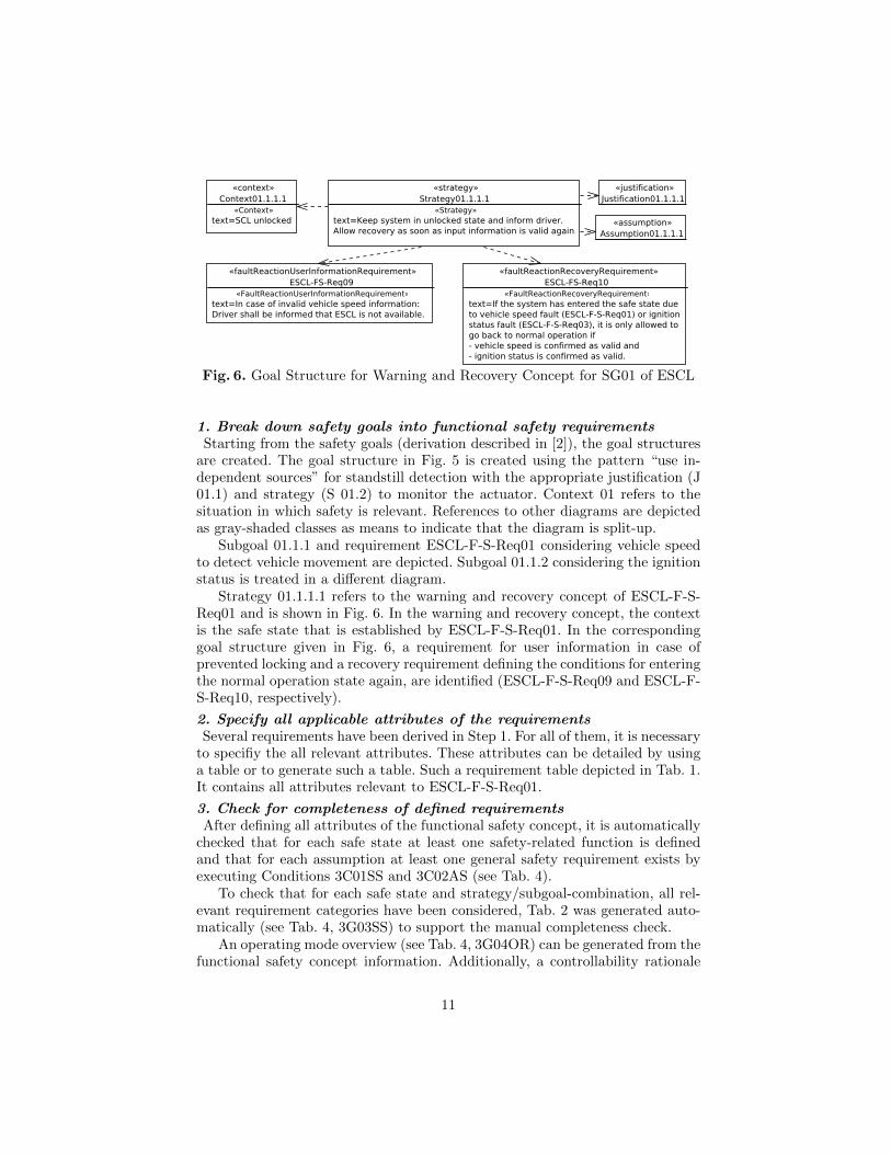
Fig. 6. Goal Structure for Warning and Recovery Concept for SG01 of ESCL
1. Break down safety goals into functional safety requirementsStarting from the safety goals (derivation described in [2]), the goal structures
are created. The goal structure in Fig. 5 is created using the pattern “use in-dependent sources” for standstill detection with the appropriate justification (J01.1) and strategy (S 01.2) to monitor the actuator. Context 01 refers to thesituation in which safety is relevant. References to other diagrams are depictedas gray-shaded classes as means to indicate that the diagram is split-up.
Subgoal 01.1.1 and requirement ESCL-F-S-Req01 considering vehicle speedto detect vehicle movement are depicted. Subgoal 01.1.2 considering the ignitionstatus is treated in a different diagram.
Strategy 01.1.1.1 refers to the warning and recovery concept of ESCL-F-S-Req01 and is shown in Fig. 6. In the warning and recovery concept, the contextis the safe state that is established by ESCL-F-S-Req01. In the correspondinggoal structure given in Fig. 6, a requirement for user information in case ofprevented locking and a recovery requirement defining the conditions for enteringthe normal operation state again, are identified (ESCL-F-S-Req09 and ESCL-F-S-Req10, respectively).
2. Specify all applicable attributes of the requirementsSeveral requirements have been derived in Step 1. For all of them, it is necessary
to specifiy the all relevant attributes. These attributes can be detailed by usinga table or to generate such a table. Such a requirement table depicted in Tab. 1.It contains all attributes relevant to ESCL-F-S-Req01.
3. Check for completeness of defined requirementsAfter defining all attributes of the functional safety concept, it is automatically
checked that for each safe state at least one safety-related function is definedand that for each assumption at least one general safety requirement exists byexecuting Conditions 3C01SS and 3C02AS (see Tab. 4).
To check that for each safe state and strategy/subgoal-combination, all rel-evant requirement categories have been considered, Tab. 2 was generated auto-matically (see Tab. 4, 3G03SS) to support the manual completeness check.
An operating mode overview (see Tab. 4, 3G04OR) can be generated from thefunctional safety concept information. Additionally, a controllability rationale
11

Safety Req-IDa ESCL-F-S-Req01 Strategy/Subgoal 01.1.1Safety Goal Ref. SG01, SG02 Operating Modes Steering column unlockedASIL Classification(if applicable)
C (D) Safe State(if applicable)
ESCL off; Steering columnunlocked
Functional Safety Requirement The steering column shall only be locked if the physical vehi-cle speed information is valid (correct and in time) and the ab-solute value is lower than PERMITTED LOCKING SPEED forVS QUALIFICATION TIME. Invalid vehicle speed information shallbe detected. The PERMITTED LOCKING SPEED shall be suchthat locking below this speed is not dangerous. b
Purpose To prevent steering column locking while vehicle is moving at speedand steering is required.
Fault Tolerant Time interval(if applicable)
VS QUALIFICATION TIME for vehicle speed faults
Reduced Functionality interval(if applicable)
n/a
Functional Redundancies (e.g. fault tol-erance) (if applicable)
No
Description of actions of the driver orother endangered persons (if applicable)
n/a
Validation Criteria for these actions(if applicable)
n/a
V&V method Set vehicle speed > PERMITTED LOCKING SPEED while ig-nition status = ignition off. Set vehicle speed < PERMIT-TED LOCKING SPEED. Fault insertion of vehicle speed signal.
V&V acceptance criteria Steering column is not locked until vehicle speed is validand for VS QUALIFICATION TIME below PERMIT-TED LOCKING SPEED.
Table 1. Attributes of ESCL-F-S-Req01
aReq-ID = name of the classbThe value for VS QUALIFICATION TIME is derived in later phases of the Func-
tional Safety Project (e.g. during creation of the Technical Safety Concept).
overview table (see Tab. 4, 3G05CR) can be generated from risk assessmentinformation. Both tables support reviews by engineers.
4. ASIL decompositionIt is possible to lower the ASIL assigned to SG01. The following decomposition
of ASIL D was chosen:
– an ASIL C(D) for no locking in case of vehicle speed,– an ASIL A(D) for no locking if the ignition status shows that ignition is on,
and– the ASIL decomposition requirement with ASIL D that excludes dependen-
cies between vehicle speed and ignition status.
The decomposition is performed according to ISO 26262.
5. Allocation of RequirementsThe functional safety requirements are allocated to the elements of the prelim-
inary architecture. This can be done with UML diagrams as depicted in Fig. 7.From these diagrams, an allocation table as depicted in Table 3 can be generated.
7. Verification ReviewTo support the reviews, the validation conditions listed in Tab. 4 are executed
on the complete case study. These validation conditions check the consistencyand correctness of the model. That is, we check
– that all necessary attributes are defined and– the functional safety concept is complete with respect to the safety goals.
12

SafetyGoalrefer-ence
Safe State Strategy(S) orSub Goal(SG) ref-erence(optional)
Safety RelatedFunctions Withthis Safe Statereference
ReducedFunctional-ity reference(if applicable)
User Informa-tion reference
Maintain SafeState / Re-covery to Nor-mal Opera-tion reference(if applicable)
SG01 ESCL off;SteeringColumnunlocked
1.1.1 (SG) ESCL-F-S-Req01 n/a ESCL-F-S-Req09 ESCL-F-S-Req10
1.1.2 (SG) ESCL-F-S-Req03SteeringColumnunlockedand fur-ther lockingprevented
1.2 (S) ESCL-F-S-Req05 n/a ESCL-F-S-Req05b
ESCL-F-S-Req05c
No enginestart al-lowed dueto reducedsafety in-tegrity
1.2.1 (SG) ESCL-F-S-Req05a n/a ESCL-F-S-Req05b
ESCL-F-S-Req05c
Table 2. Safe State and Requirement References
Fig. 7. Allocation of Functional SafetyRequirements to Logical Elements
F-S
-Req.
ID
Req.
text
ASIL
Subsys-tem/Component
KV
MP
ow
er
Lin
eK
-Lin
eSC
LA
BS
EC
MD
IMP
ow
er
But.
ESCL-F-S-Req01 . . . C (D) X X X. . .
Table 3. Allocation of FunctionalSafety Requirements to Logical Ele-ments
6 Related Work
Basir, Denny, and Fischer [9] present goal structures for safety cases in theautomotive sector. They do not focus on the technical realization but considerthe entire safety process with their documents as entities.
Dittel and Aryus [13] present an overview of V&V activities at Ford MotorCompany applied for the lane keeping aid system. This paper also presentselements of the process for functional safety according to ISO 26262, i.e. theanalysis activities.
Sinha [14] illustrates an example of a brake-by-wire system for road vehiclesincluding a safety and reliability analysis compliant to ISO 262626. The conclu-sions derive suggestions for future projects, such as that the system architectureof road vehicles shall support the detection of failures and have the means tostill provide desired services until the failures are repaired.
Palin et al. [15] provide guidelines for safety practitioners and researchers tocreate safety cases compliant to the ISO 26262 standard. The authors proposeextensions of the Goal Structuring Notation, patterns, and a number of re-usable
13

safety arguments for creating safety cases. For confidentiality reasons, the au-thors cannot show example instantiations of their patterns or generic arguments.
Conrad et al. [16] compares software tools that support ISO 26262 certifica-tion. The authors identified a list a qualification requirements for selecting ISO26262 support tools. The publication also contains a report about Conrad etal.’s experience with these tools.
Hillebrand et al. [17] discuss how to develop electric and electronic archi-tectures (EEA) compliant with the ISO 26262 standard. The authors focus onsafety requirements during early development phases. Hillenbrand et al. presenta method for eliciting safety requirements, and mapping their safety concerns tofunctions of design artifacts. Previously, Hillebrand et al. [18] proposed a model-based and tool- supported approach for the failure mode and effect analysis(FMEA) of EAAs complaint to ISO 26262. The authors contribute a formalizedmethod for eliciting and analyzing data for a FMEA.
Habli et al. [19] propose a process for model-based assurance for justifyingautomotive functional safety. They use SysML and GSN as graphical notations.Their goal and ours is similar. We both want to support a method based on ISO26262 to derive functional safety requirements. In contrast to their work, we useUML, which gives us a broader spectrum of modeling possibilities. Furthermore,we provide tool support for our method and equipped our approach with formalconsistency checks on the model. These checks can be automatically checked byour tool. In addition, our way of modeling allows us to trace elements within ourmodels.
Born et al. [20] report on lessons learned from applying a model-based ap-proach for ISO 26262 certification. The authors also discuss the advantages ofmodels instead of text in the ISO 26262 certification process.
7 Conclusions and Future Work
The method presented in this paper has been and currently is applied in severalFord of Europe projects. However, the formal validation conditions and toolsupport were and are not part of these projects. Both have been developed ascontribution of this paper. Still, we are confident that the validation conditionsin combination with the tool support ensure at least the same consistency andcorrectness as the currently used approach, with the benefit of less effort needed.Furthermore, the method is the logical next step to the work presented in [2].
Our contribution has the following main benefits:
– a structured and model-based approach for deriving functional safety con-cepts for the automotive domain compliant to ISO 26262
– a UML profile to express all required elements for a functional safety conceptcompliant to ISO 26262
– computer-aided validation of created UML models via executable OCL ex-pressions, e.g., checks for correctness and completeness of the model
– enforcing considering adequate assumptions and safety reasoning by explic-itly checking that these are present (by computers) and their soundness (byhuman experts)
14

Functional safety concepts in practice are currently document-based using textprocessing and drawing tools. If the documents are created using a UML tool,the information can be checked for consistency and the document can be cre-ated. With our method, a seamless integration into a model-based developmentprocess is possible. In the future, we intend to apply our method and tool indifferent projects. In addition, we plan to focus on technical safety requirementsgeneration and metric derivation.
Step ID Condition1 1M01UE Names of the elements in the goal structure (safety goal, subgoal, strategy, assumption,
context, justification, functional safety requirement or subtype) are unique.1 1M02DG Dependencies with the stereotypes �supportedBy�, �alternativelySupportedBy� and
�optionallySupportedBy� point from classes with the stereotypes �SafetyGoal�,�SubGoal�, or �Strategy� to �SubGoal�, �Strategy�, or subtypes of�FunctionalSafetyRequirement�.
1 1M03DS A dependency between 2 strategies is not allowed.1 1M04DC A dependency with the stereotype �inContextOf� point from classes with the stereo-
types �SafetyGoal�, �SubGoal�, or �Strategy� to �Justification�, �Context� or�Assumption�.
2 2M01RA For each functional safety requirement and their subtypes: the operating mode is requiredto be set, the purpose, the text, the validation and verification method, and its acceptancecriteria is required not to be empty.
2 2M02SG If the dependency with stereotypes �supportedBy�, �alternativelySupportedBy� or�optionallySupportedBy� point from a class with stereotype �SubGoal� to a class with astereotype being subtypes of �FunctionalSafetyRequirement�, its attribute subGoal pointsto the source of the dependency.
2 2M03SS If the dependency with stereotypes �supportedBy�, �alternativelySupportedBy� or�optionallySupportedBy� point from a class with stereotype �Strategy� to a class with astereotype being subtypes of �FunctionalSafetyRequirement�, its attribute strategy pointsto the source of the dependency.
2 2M04RA For a class with the stereotype �SafetyRelatedFunctionRequirement�, ASIL, at least onesafe state, and fault tolerant are specified.
2 2M05RA For a class with the stereotype�EmergencyOperationRequirement�, ASIL, at least one safestate is referred to, and fault tolerant time is specified.
2 2M06RA For a class with the stereotype �FaultReactionUserInformationRequirement�, at least onesafe state is referred to, and a description of actions by the driver or other persons arespecified.
2 2C07RA For a class with the stereotype �FaultReactionRecoveryRequirement�, at least one safetygoal and one safe state are referred to.
2 2M08RA For a class with the stereotype �ASILDecompositionRequirement�, at least one safety goalis referred to.
3 3C01SS Each a state or state machine with the stereotype�SafeState� is referred to by a class withthe stereotype �SafetyRelatedFunctionRequirement�.
3 3C02AS From each class with the stereotype �Assumption�, a dependency with the stereotype�supportedBy� points to a class with the stereotype �GeneralRequirement�.
3 3G03SS For each class with the stereotype�SafetyRelatedFunctionRequirement�, all safe states andthe related strategies or subgoals are determined. For each combination of safe state and therelated strategy or subgoal, references to emergency operation requirements, user informationrequirements, and recovery requirements are listed in a table.
3 3G04OR For each state or state machine, the name of the classes with the stereotype�SafetyRelatedFunctionRequirement� are listed in a table. The line is removed, if all sub-states are referenced or if the containing state is referenced.
3 3G05CR The controllability rationales from all assessment together with the addressing safety goalsare listed in a table.
5 5M01AR Dependencies with the stereotype �allocatedTo� points from subtype of�FunctionalSafetyRequirement� to �LogicalElement�.
Table 4. Validation Conditions
15
References
1. Int. Organization for Standardization (ISO): Road Vehicles – Functional Safety.ISO 26262 (2011)
2. Beckers, K., Frese, T., Hatebur, D., Heisel, M.: A Structured and Model-BasedHazard Analysis and Risk Assessment Method for Automotive Systems. In: Procsof the 24th IEEE Int. Symposium on Software Reliability Engineering, IEEE Com-puter Society (2013) 238–247
3. UML Revision Task Force: OMG Unified Modeling Language: Superstructure.Object Management Group (OMG). (May 2010)
4. UML Revision Task Force: OMG Object Constraint Language: Reference (Febru-ary 2010)
5. Kelly, T.P.: A Systematic Approach to Safety Case Management. In: Procs 28thSymp. on Applied Computing, Detroit, Society for Automotive Engineers (2004)
6. Spriggs, J.: GSN - The Goal Structuring Notation: A Structured Approach toPresenting Arguments. Springer; 2012 edition (2012)
7. Group, G.S.N.W.: GSN community standard version 1 (2011)8. International Organization for Standardization (ISO) and International Elec-
trotechnical Commission (IEC): Functional safety of electrical/electronic/pro-grammable electronic safety-relevant systems. ISO/IEC 61508 (2000)
9. Basir, N., Denney, E., Fischer, B.: Deriving safety cases for hierarchical structurein model-based development. In: SAFECOMP 2010. LNCS 6351, Springer (2010)68–81
10. Atos Origin: Papyrus UML Modelling Tool. (Feb 2011)http://www.papyrusuml.org/.
11. Eclipse Foundation: Eclipse - An Open Development Platform. (2011)http://www.eclipse.org/.
12. Eclipse Foundation: Eclipse Modeling Framework Project (EMF) (June 2012)http://www.eclipse.org/modeling/emf/.
13. Dittel, T., Aryus, H.J.: How to ’survive’ a safety case according to ISO 26262. In:SAFECOMP 2010. LNCS 6351, Springer (2010) 97–111
14. Sinha, P.: Architectural design and reliability analysis of a fail-operational brake-by-wire system from ISO 26262 perspectives. Reliability Engineering & SystemSafety (2011) 1349 – 1359
15. Palin, R., Ward, D., Habli, I., Rivett, R.: ISO 26262 safety cases: Compliance andassurance. In: System Safety, 2011 6th IET Int. Conf. on. (2011) 1–6
16. Conrad, M., Munier, P., Rauch, F.: Qualifying software tools according to ISO26262. In: Proc. Dagstuhl-Workshop Modellbasierte Entwicklung eingebetteterSysteme (MBEES10). (2010)
17. Hillebrand, J., Reichenpfader, P., Mandic, I., Siegl, H., Peer, C.: EstablishingConfidence in the Usage of Software Tools in Context of ISO 26262. In: ComputerSafety, Reliability, and Security. LNCS. Springer (2011) 257–269
18. Hillenbrand, M., Heinz, M., Adler, N., Matheis, J., Muller-Glaser, K.: Failuremode and effect analysis based on electric and electronic architectures of vehiclesto support the safety lifecycle ISO/DIS 26262. In: Rapid System Prototyping(RSP), 2010 21st IEEE International Symposium on. (June 2010) 1–7
19. Habli, I., Ibarra, I., Rivett, R., Kelly, T.: Model-Based Assurance for JustifyingAutomotive Functional Safety. In: SAE Technical Paper 2010-01-0209. (2010)
20. Born, M., Favaro, J., Kath, O.: Application of ISO DIS 26262 in Practice. In:Procs of the 1st Workshop on Critical Automotive Applications: Robustness &Safety. CARS ’10, New York, NY, USA, ACM (2010) 3–6
16