system solutions - sintef · iea hpp annex 32 is a corporate research project on technical building...
TRANSCRIPT

Fin
al
rep
ort
An
nex 3
2 p
art
1
International Energy Agency
Heat Pump Programme
System solutions Multifunctional heat pump systems for the application in low energy houses
Worked out by Carsten Wemhoener (Editor) Operating Agent IEA HPP Annex 32 Institute of Energy in Building University of Applied Sciences North-Western Switzerland E-Mail: [email protected]
IEA HPP Annex 32 Economical heating and cooling systems for low energy houses
March 2011
Swiss Federal Office of Energy SFOE

Imprint
IEA HPP Annex 32 " Economical heating and cooling systems for low energy houses" The work presented here is a contribution to the Annex 32 in the Heat Pump Programme (HPP) Implementing Agreement of the International Energy Agency (IEA) Operating Agent (Switzerland): Institute of Energy in Building, Univ. of Applied Sciences Northwestern Switzerland, Muttenz Carsten Wemhöner, [email protected] National team leaders in IEA HPP Annex 32 Austria: Institute of thermal engineering (IWT), Graz Technical University, Austria Ao. Univ. Prof. Dr. René Rieberer, [email protected] Canada: Laboratoire des technologies de l`énergie (LTE), Hydro Québec, Shawinigan, Canada Vasile Minea, PhD, [email protected] France: Electricité de France, Research&Development, Department ENERBAT, Moret-sur-Loing, France Catherine Martinlagardette, [email protected] Germany: Fraunhofer Institute of Solar energy systems (FhG-ISE), Freiburg (Brsg.), Germany Marek Miara, [email protected] Japan: Graduate School of Engineering, Hokkaido University, Sapporo, Japan Prof. Dr. Eng. Katsunori Nagano, [email protected] The Netherlands: Agentschap NL, Utrecht, Netherlands Onno Kleefkens, [email protected] Norway: SINTEF Energy Research, Trondheim, Norway Maria Justo Alonso [email protected], Dr. Ing. Jørn Stene (2006-08) [email protected] Sweden: SP Technical Research Institute of Sweden, Borås, Sweden Svein Ruud, [email protected] Switzerland: Institute of Energy in Buiding, Univ. of Applied Sciences Northwestern Switzerland, Muttenz Prof. Dr. Thomas Afjei, [email protected] USA: Oak Ridge National Laboratory, Oak Ridge, Tennessee, United States of America Van D. Baxter, [email protected], Arun Vohra (retired 2008), Department of Energy, Washington DC
IEA HPP Annex 32
IEA HPP Annex 32 is a corporate research project on technical building systems with heat pumps for the application in low energy houses. The project is accomplished in the Heat Pump Programme (HPP) of the International Energy Agency (IEA). Internet: http://www.annex32.net

3
Summary
The report gives an overview of marketable heat pump system solutions applied in low en-ergy houses in the participating countries of IEA HPP Annex 32. In low energy houses, loads change significantly, in particular the space heating needs are notably reduced, and the share of DHW increases. Moreover, mechanical ventilation may be required to guarantee the necessary air exchange due to the air-tight building construction, and in recent years market development show an increasing integration of a comfort cooling option in the system layouts. Therefore, integrated multifunctional heat pumps have advantages of covering different building functions at the same time, e.g. in simultaneous space cooling and DHW operation. The report is intended to facilitate a system decision by giving tree depiction as overview of system solutions. Due to the above described different loads and building services the sys-tem classification is based on the integrated system functionalities. First, an overview of heat source and heat emission systems is given. In Europe, outside air and the ground are the predominant heat sources used in the residential sector. However, in low energy building with mechanical ventilation system, exhaust air is increasingly used as heat source, in particular in ultra-low energy houses, where a mechanical ventilation is al-ways installed. In Japan and the USA air-source heat pumps are very common. In the USA, central ducted systems are used, while in Japan, heat pump air conditioners or multi-split system for heating and cooling are mainly applied. The top level system classification distinguishes between integrated ventilation function, cooling function, combined space heating and DHW functions and finally only a single func-tionality of the heat pump without integration, which are currently common on the market. Ventilation based integrated system solutions can be distinguished in exhaust air systems and systems with balanced ventilation. Exhaust air systems are common for DHW produc-tion, but also integrated solutions with space heating function are on the market. Balanced ventilation systems are mostly designed for the space heating and eventually active space cooling function by reverse heat pump operation, where the exhaust air is used as source (heating) or sink (cooling) and the supply air is used for distribution and emission. If the ex-haust air heat pump can be switched to a DHW storage, also a DHW function can be inte-grated. So-called ventilation compact units additionally include a passive ventilation heat re-covery and cover the functions space heating, ventilation and DHW, some also include a cooling option by reverse operation. However, the capacity of the exhaust air is limited by the hygienic ventilation rate to about 1.0-1.5 kW depending on the volume flow rate, so ground-to-air heat exchangers to increase the inlet temperature and an additional outdoor air volume flow for the heat pump evaporator are used to increase the heating capacity. Systems with integrated cooling functions and no coupling to the ventilation can be differen-tiated in ground- or water-coupled passive cooling and active cooling by reverse operation of the heat pump and distinguished by the heat source. For combined operating space and water heating heat pumps, alternate and simultaneous configurations exist. In Europe mainly alternate operation by switching the heat pump from space to DHW heating is found on the market, while in Northern America, simultaneous op-eration by desuperheater is more common. In the category of systems with single functionality, standard configurations for space heat-ing-only are given as well as heat pump water heaters are described, in particular CO2 heat pump water heaters, which have reached a considerable market share in Japan.

4

5
Contents
IMPRINT ........................................................................................................................... 2
SUMMARY ........................................................................................................................ 3
CONTENTS ...................................................................................................................... 5
PREFACE ......................................................................................................................... 7
1 INTRODUCTION ........................................................................................................ 9
2 SYSTEM CLASSIFICATION ..................................................................................... 11
2.1 SYSTEM CLASSIFICATION OF HEAT PUMPS FOR LOW ENERGY HOUSES ...................... 11 2.2 DISCUSSION OF HEAT SOURCES FOR HEAT PUMP SYSTEMS ..................................... 11 2.3 DISCUSSION OF HEAT EMISSION SYSTEMS FOR HEAT PUMPS .................................... 15
3 VENTILATION AIR SOURCE HEAT PUMP SOLUTIONS ........................................ 19
3.1 VENTILATION SYSTEMS ......................................................................................... 19 3.2 CLASSIFICATION OF VENTILATION AIR SOURCE HEAT PUMP SOLUTIONS ..................... 20 3.3 EXHAUST-AIR HEAT PUMP WATER HEATER .............................................................. 21 3.4 EXHAUST-AIR HEAT PUMP FOR SPACE HEATING AND DHW ...................................... 21 3.5 ACTIVE HEAT RECOVERY BY THE HEAT PUMP .......................................................... 22 3.6 COMPACT UNITS ................................................................................................... 23 3.7 SYSTEMS FOR PREHEATING THE INLET AIR WITH THE GROUND ................................. 25 3.8 ADDITIONAL FUNCTIONS OF THE VENTILATION SYSTEM ............................................ 25
4 HEAT PUMP SYSTEMS WITH SPACE COOLING OPTION .................................... 27
4.1 AIR-TO-AIR AIR-CONDITIONERS AND HEAT PUMPS ................................................... 28 4.2 AIR-TO-WATER HEAT PUMPS ................................................................................. 36 4.3 GROUND- AND WATER SOURCE HEAT PUMPS .......................................................... 37
5 HEAT PUMP SYSTEMS FOR SPACE HEATING AND DHW ................................... 39
5.1 SYSTEMS WITH ALTERNATE OPERATION ................................................................. 39 5.2 SYSTEMS WITH SIMULTANEOUS OPERATION ........................................................... 41 5.3 SYSTEMS WITH INTEGRATION OF SOLAR ENERGY .................................................... 43
6 HEAT PUMP SYSTEMS WITH SINGLE FUNCTIONALITY ...................................... 45
6.1 SPACE HEATING-ONLY HEAT PUMPS ....................................................................... 45 6.2 HEAT PUMP WATER HEATERS ................................................................................ 46
7 CONCLUSIONS ....................................................................................................... 49
8 ACKNOWLEDGEMENT ........................................................................................... 51
9 REFERENCES ......................................................................................................... 53
10 APPENDIX ............................................................................................................ 55
A MARKET OVERVIEW ON HEAT PUMP COMPACT UNITS .................................... 56
B MARKET OVERVIEW ON RECENT MINI SPLIT UNITS .......................................... 59
C SUMMARY OF COMMON HEAT PUMP TYPES ...................................................... 65
C.1 AIR-TO-AIR HEAT PUMPS – SUMMARY ................................................................... 65 C.2 EXHAUST AIR – VENTILATION AIR HEAT PUMPS – SUMMARY ................................... 66

6
C.3 BALANCED VENTILATION AIR HEAT PUMPS – SUMMARY .......................................... 67 C.4 AIR-TO-WATER HEAT PUMPS – SUMMARY ............................................................. 68 C.5 BRINE- AND WATER-TO-WATER HEAT PUMPS – SUMMARY ..................................... 69 C.6 COMPARISON OF VENTILATION AIR HEAT PUMPS IN NORWAY ................................... 70

7
PREFACE
Introduction to IEA HPP Annex 32 Since the mid of the nineties low energy buildings with a significantly reduced energy con-sumption down to ultra-low energy standard (typical space heating energy need of 15 kWh/(m2a)) or even net zero energy consumption (on an annual basis by an integration of on-site renewable energy systems) have been realised. These building concepts recently show strong market growth in different European countries. Many governments address the spread of low energy buildings as a major strategy to reach climate protection targets according to the Kyoto protocol. Heat pump markets are growing in many countries as well. Low energy buildings have significantly different load characteristics compared to conven-tional existing buildings. This requires adapted system solutions to entirely use energy-efficiency potentials for the remaining energy needs. Integrated heat pump solutions have favourable features for the use in low energy houses. The main advantages are the potential for internal heat recovery and simultaneous operation to cover different building needs at the same time as well as installation space and cost benefits. This leads to a significantly improved system performance in an adequate capacity range to reduce primary energy consumption and cut CO2-emissions and costs. However, in many countries, no adequate system solutions are available on the market or energy performance of available and newly-introduced low energy house technology is not yet approved by field experience. Therefore, system development and field approval of func-tionality and real-world operational performance of the systems are needed. These are the main working areas of IEA HPP Annex 32. Main objectives of IEA HPP Annex 32 The main objectives of the IEA HPP Annex 32 are the further development and field monitor-ing of integrated heat pump systems for the use in low energy buildings, leading to the fol-lowing objectives: • To characterise the state-of-the-art in the different participating countries • To assess and compare the energy performance of different system solutions for the
residential low energy house sector • To develop and lab-test new system solutions of integrated heat pumps in the low energy
house capacity range including the use of natural refrigerants • To accomplished field tests of new developments and marketable systems and to docu-
ment best practice examples • To disseminate the results Results of the IEA HPP Annex 32 The results of IEA HPP Annex 32 comprise: • Overview of market system solutions of integrated heat pumps for low energy houses • Design recommendations of the standard system solutions • New system developments as prototypes including lab-test and simulation results • Documentation of field monitoring results of new and marketable systems • Dissemination of results by a website, workshop presentation and reports

8

9
1 INTRODUCTION
Energy needs in low energy buildings differ significantly from energy needs in the existing building stock. Space heating energy needs have been reduced significantly since the mid of the nineties. Thus, DHW energy needs constitute a bigger share of the total heating re-quirement. Further functionalities of the building technology have been added, such as a mechanical ventilation system, which is increasingly installed in low energy houses. More-over, a cooling function may be added due to rising temperature in the course of climate change and increasing request for indoor comfort. Therefore, system configurations have to be adapted to the changed situations and func-tionalities. Interesting concepts are integrated system configurations, since
• Waste heat, e.g. from the exhaust air, can be recovered for other building needs • Different building needs can be covered simultaneously with efficiency gains, e.g. in case
of a combined space cooling and DHW operation
Heat pumps have several advantages as core component of integrated systems in low en-ergy houses.
• Highly-efficient with proper design of the system, use of ambient heat • Available on the market down to very low capacity ranges • Environmentally-sound technology, no dependency on fossil fuels
(except for the electricity generation) • With renewably generated electricity entirely CO2-free operation possible • Space heating and -cooling with one generator possible • Simultaneous supply of different building services (e.g. space heating and DHW) • Further reduction of building losses possible (e.g. exhaust-air heat pumps) • Depending on the boundary conditions economically favourable • Independent of rising oil and gas prices (as far as electricity prices are not affected)
This report gives an overview of marketable system solutions with multifunctional heat pumps. Due to the market introduction state, the report is restricted to electrically-driven heat pumps. The classification of system solutions is based on the functionality of the system. In chapter 2 an overview of the system classification and a discussion of source- and sink systems are given. In chapter 3, ventilation-based heat pump solutions are presented in more detail. Chapter 4 treats system solutions with cooling option independent of the ventilation system. Chapter 5 deals with integrated heat pump solutions for space heating and DHW operation, and gives an overview of the integration of solar and heat pump systems. Chapter 6 shortly covers heat pumps with single functionalities, comprising CO2 heat pump water heaters. In the conclusion an outlook on further systems developments is given.

10
11
2 SYSTEM CLASSIFICATION
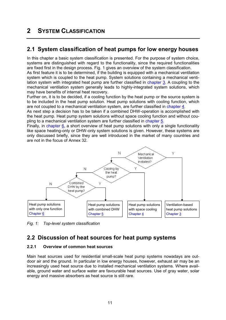
2.1 System classification of heat pumps for low energy houses In this chapter a basic system classification is presented. For the purpose of system choice, systems are distinguished with regard to the functionality, since the required functionalities are fixed first in the design process. Fig. 1 gives an overview of the system classification. As first feature it is to be determined, if the building is equipped with a mechanical ventilation system which is coupled to the heat pump. System solutions containing a mechanical venti-lation system with integrated heat pump are further classified in chapter 3. A coupling to the mechanical ventilation system generally leads to highly-integrated system solutions, which may have benefits of internal heat recovery. Further on, it is to be decided, if a cooling function by the heat pump or the source system is to be included in the heat pump solution. Heat pump solutions with cooling function, which are not coupled to a mechanical ventilation system, are further classified in chapter 4. As next step a decision has to be taken if a combined DHW-operation is accomplished with the heat pump. Heat pump system solutions without space cooling function and without cou-pling to a mechanical ventilation system are further classified in chapter 5. Finally, in chapter 6, a short overview of heat pump solutions with only a single functionality like space heating-only or DHW-only system solutions is given. However, these systems are only discussed briefly, since they are well introduced in the market of many countries and are not in the focus of Annex 32.
Fig. 1: Top-level system classification
2.2 Discussion of heat sources for heat pump systems 2.2.1 Overview of common heat sources Main heat sources used for residential small-scale heat pump systems nowadays are out-door air and the ground. In particular in low energy houses, however, exhaust air may be an increasingly used heat source due to installed mechanical ventilation systems. Where avail-able, ground water and surface water are favourable heat sources. Use of gray water, solar energy and massive absorbers as heat source is still rare.
Heat pump solutions with only one function Chapter 6
Heat pump solutions with combined DHW Chapter 5
Ventilation-based heat pump solutions Chapter 3
Heat pump solutions with space cooling Chapter 4

12
Regarding large-scale heat pumps for multi-family houses, blocks of flats or apartment houses, ground and surface water as well as borehole fields are common heat sources. 2.2.1.1 Outdoor air Outdoor air is one of the most frequently used heat sources for residential heat pumps, since outdoor air is available everywhere and the connection of the source to the heat pump is generally easy and cheap. However, source temperature is opposite to the heating needs and in cold wintertime the capacity and performance is limited. Efficiency and capacity gains may be achieved, if the air is partly sucked from warm surroundings (uninsulated cellar, ga-rage, exhaust air). Up to +7°C outdoor air temperature a defrosting operation has to be pro-vided, and condensate has to be rejected in a frost secure pipe. Noise protection measures have to be carefully considered. Smaller systems (5-50 kW) are usually put inside the build-ing unless no space in the building is available. Split systems have an outdoor (evaporator) and indoor (condenser) unit and are used, if the necessary air volume flow cannot be directly connected to the system placed inside the building. 2.2.1.2 Ground The ground can be used both as heat source and heat sink for systems with space heating and space cooling operation. However, the annual energy balance has to be considered. Seasonal storage of larger amounts of energy in the ground is only possible for field of bore-holes. In single borehole systems the stored heat escapes in the ground by heat conduction or ground water flow. Most common systems of ground heat sources are horizontal ground collectors and vertical borehole heat exchangers.
Fig. 2: Horizontal collector and ditch collector (here as additional source for exhaust air heat pumps (Fehrm, 2005) Horizontal collectors are usually buried in the ground at a depth of 1.2-1.5 m below the sur-face, i.e. under the level, where frosting of the ground occurs. They are easier to install, since no drilling is needed, but require quite a lot of digging and space in the garden. A vari-ant are ditch collectors and ground baskets. Ditch collectors comprise a set of vertical tubes connected by a horizontal supply and return pipe, which are buried in a ditch in the ground. The used area is thus smaller than for horizontal collectors. Ground basket heat exchangers depicted in Fig. 3 are winded coils which are buried in the ground in 1.5-5 m depth. Another variant are direct expansion (DX) systems, where the refrigerant is directly evapo-rated in the ground loop without an intermediate heat exchange fluid (open loop system). Advantages are less auxiliary energy consumption, since no source pump for the circulation of the intermediate heat exchange fluid is needed, and higher evaporation temperatures due to the direct evaporation without temperature drop in the evaporator. However, pipes have to be thoroughly sealed to avoid leakage of refrigerant into the ground and the atmosphere.

13
Fig. 3: Ground basket heat exchanger coil
Vertical borehole heat exchangers require the drilling of the borehole. Most common bore-hole heat exchangers are of double U-tube type, but also single U-tube and coaxial types are used. Main design aspects are the type of soil, the number of boreholes, the diameter and distance of boreholes and the pressure drop. To evaluate the ground characteristics, mostly for large-scale systems, so-called thermal response tests are accomplished. Most systems use brine, but with an adequate design to exclude freezing in the borehole heat exchanger, systems can also be operated with water. Cost of drilling is dependent on the ground charac-teristics. The drilling of borehole heat exchangers usually requires permission. Particular sites may be exempted of drilling, e.g. drinking water or geologically instable areas.
Fig. 4: Borehole heat exchanger in heating and cooling mode (left, Stene, 2007) and sys-tem layout and working principle of the CO2 heat pipe (right, Heinz et al., 2007)
A recent development concerning vertical borehole heat exchangers is a heat pipe system with the working fluid CO2. The working fluid CO2 is evaporated in the heat exchanger below the ground flows to the heat exchanger at the top of the system, where the vapour is con-densed by the evaporating refrigerant and returned to the lower end by gravity. As in direct expansion systems no source pump, which in conventional systems is one of the major con-sumers of auxiliary energy, is needed due to the natural heat pipe cycle, which increases the system performance. Additionally, the heat transfer is enhanced by the evaporation and condensation and due to the harmless working fluid CO2, the system can also be installed in water protection areas. Fig. 4 right illustrates the system layout and the working principle of the CO2 heat pipe. A pilot system is monitored in the Wattwerk® (http://www.wattwerk.ch), the first business building acc. to Swiss MINERGIE-P® standard.

14
2.2.1.3 Exhaust air Exhaust air can be used as heat source in systems with a mechanical ventilation system. Since in many low energy houses, a mechanical ventilation system is installed due to the air tightness of the building, exhaust air is a common heat source in low energy buildings. How-ever, due to volume flow rates restricted to the hygienic necessary air exchange the capacity is limited, in particular since most balanced ventilation systems are equipped with a passive ventilation heat recovery, i.e. a heat exchanger to preheat the outside air with the return air. In order to augment the capacity, variants with an additional ground source have been de-veloped as shown in Fig. 2, or the exhaust air is mixed with an additional outdoor air flow at the inlet of the evaporator. 2.2.1.4 Water The use of ground water depends strongly on the availability. Ground water has the best temperature conditions with a year-round nearly constant temperature in the range of 10°C. Normally, ground water is used directly by a source and sink well. Even though ground water is an attractive thermal heat source the cost for the connection to the source is the highest. Surface water of lakes and rivers has lower temperatures and is normally used indirectly by an intermediate brine cycle either by a well or by a heat exchanger in the water source, which however has to be protected against pollution. 2.2.1.5 Grey water Grey water is a promising heat source due to the temperature level, but is only used in larger buildings so far. 2.2.2 Choice of heat source system The most important criteria for the choice of the heat source are
• availability • temperature level • capacity and • cost.
The heat source with a constant availability and the highest temperature level should be chosen. The heat sources water and the ground are the most favourable, but are not avail-able everywhere and have higher costs for the connection of the source to the heat pump. In low energy houses with low heat loads and installed ventilation systems exhaust air may be-come an interesting heat source, but its capacity is limited by the required ventilation flow rate. Thus, the use of hydrid sources, in particular the combination of exhaust air and outside air or the combination of exhaust air with the ground are under development and are partly available on the market. An overview of the characteristics of most common heat sources is given in Tab. 1.

15
Tab. 1 Characteristic of most common heat sources
Heat sources Criteria Outdoor air Ground (Ground) water Exhaust air Availability everywhere high restricted in connection with
ventilation system Capacity of source
depending on volume flow rate
range of capacity: • Borehole: ≈50 W/mgroundHX
• Collector, dry soil: ≈10 W/m
• Collector, wet soil: ≈35 W/m
range of capacity: • Ground water:
150-200 l/(h⋅kW) • Surface water:
300–400 l/(h⋅kW)
limited in case of hygienic neces- sary air exchange
Temperature range
-20°C - 40°C 1°C - 15°C 8°C – 13°C 20 - 28°C
Frosting risk up to ≈7°C out-door air tempera-ture
in case of under-dimensioned short ground HX
none in case of coup- ling with ventila- tion heat recovery
Coherence SH need and source capacity
incoherent low middle constant
Passive cooling possible
no yes yes no
Required space depending on type
• low (borehole) • high (collector)
low low
Permission none required required none Configuration direct use • intermediate cycle
brine or water • direct expansion
of refrigerant
• direct • intermediate cy
cle depending on water quality
direct use
Cost of heat source (CH)
low average high low, if ventilation system is in- stalled anyway
Further requirements
• consideration of operation limits of the heat pump
• consideration of noise issues
access/permission for drilling required
• permission re- quired
• consideration of water quality
• consideration of operation limits of the heat pump
• consideration of noise issues
2.3 Discussion of heat emission systems for heat pumps 2.3.1 Choice of emission system The main criteria for the choice of the emission (or heating and cooling distribution) systems are the required temperature level and cost. High efficiencies of the heat pump are mainly possible with emission systems which use temperature levels close to the indoor air temperature. While increasingly applied in office buildings, thermally-activated building systems (TABS) are still rare in residential buildings, so floor heating systems are the most common solution for the emission system in central Europe. On the other hand, design and installation costs are the second argument, which is best for decentral air systems or central ventilation systems which are installed anyway and used for heating and cooling energy transport, since the hydronic distribution is saved. Radiator and convector systems are not so common in low energy houses with heat pumps due to the higher required temperature by the reduced surface.

16
Tab. 2 gives a summary of the characteristic of different types of emission system for space heating and cooling based on Recknagel, Sprenger and Schramek (2006) and Baxter (2009). Tab. 2: Overview of different space heating emission systems in low energy buildings Space heating Criteria TABS Floor heating Radiators/
Convectors Air heating
Thermal Capacity very high high rather low low Temperature re-quirements
below 30°C 30°C – 40°C 40°C – 70°C Depending on volume flow Up to 50°C with only hygienically required air flow
Heating capacity max ~40 W/m2
(heating surface) max. 80 W/m2 (heating surface)
max. 1300 W/m2
(heating surface) max. 10 W/m2
(energy reference area)
Use of solar gains depending on control concept: (may be restricted due to hot floor)
depending on control concept: may be restricted (due to hot floor)
good good
Controllability • Slowest control-lability due to the highest thermal mass
• self regulation effect at low ex-cess tempera-ture
• Slow controlla-bility due to the high thermal mass
• self regulation effect at low ex-cess tempera-ture
• Fast control • Fast control of the reheating of the air flow
Comfort Temperature asymmetry
low low depending on po-sitioning
depending on air inlet
Radiative fraction high high rather low (0.25 – 0.15, max. 0.4)
depending on air inlet
Air flow low low depending on po-sitioning and con-vective fraction high
depending on air inlet and convec-tive fraction aver-age
Other items Space demand none low high none Specific advantages
Self regulation effect Very low supply temperature re-quirements
Self regulation effect Low supply tem-perature require-ments
Fast control and therefore good use of solar gains due to cold floor
Cost advantages since no further installation for heat emission re-quired
Restrictions Restrictions re-garding the floor covering
Restrictions re-garding the floor covering
Restrictions re-garding the loca-tion of the radia-tors
Restrictions with regard to the heating capacity
Application for SC possible possible With convectors possible, with ra-diators supple-mentary, but rare
possible

17
Tab. 3: Characteristics of different space cooling emission systems (based on Recknagel-Sprenger, 2006, Baxter, 2009)
Space cooling Criteria TABS Floor/Ceiling Cooling
panels Central air distribution
Air convectors
Thermal Capacity very high high middle low low Max. cooling ca-pacity
40 W/m2 95 W/m2 120 W/m2 40–60 W/m2 50–200 W/m2
Min. water tem-perature
17°C 16°C 16°C ~10°C for wa-ter-to-air fan coils 8-10°C refriger-ant evaporating temperature for air-toair or wa-ter-to-air heat pumps
16°C
Controllability poor slow good fast fast Comfort good at
low loads very good very good good good at low
loads Use for heating and cooling possi-ble
Base load, additional systems with fast control useful
depending on control con-cept: may be restricted (due to hot floor and exponent of the emission system)
good good good
Retrofitting not possi-ble
depending on circumstances
possible depending on circumstances
possible

18

19
3 VENTILATION AIR SOURCE HEAT PUMP SOLUTIONS
3.1 Ventilation systems With the higher air-tightness of low-energy buildings, low and ultra-low energy houses are increasingly equipped with mechanical ventilation systems in order to guarantee the hygieni-cally necessary air exchange as well as for comfort reasons and to reduce ventilation losses. Ventilation systems can mainly be classified according to the following criteria: • Exhaust-air-only or balanced ventilation systems (i.e. supply air flow equal to exhaust air
flow) • Central or decentral • With and without ventilation heat recovery (also called passive heat recovery)
Exhaust air systems mainly guarantee an extraction of odour, germs and prevent building damage due to high moisture rates by extracting the exhaust air through an exhaust air duct system. The supply air gets into the house by infiltration through special fresh air wall valves.
Balanced ventilation systems with a separate supply air and exhaust air fan can guarantee a continuous supply of the hygienically necessary air volume flow rate. Exhaust air is extracted of the kitchen and bathroom areas, while the supply air enters the living and sleeping rooms. Air-quality is improved by filtering the inlet air and a passive ventilation heat recovery by an air-to-air heat exchanger in the ventilation ducts is possible. The ventilation losses can typi-cally be reduced by about 60% by cross-flow heat exchanger, with highly-efficient cross-counterflow or counterflow heat exchangers above 80%. Rotary heat exchangers reach val-ues about 75% and have the advantage, that also the moisture of the return air from the dwelling can be recovered, so-called enthalpy recovery. However, transfer of odour from the exhaust to the supply air flow may be critical. Other recuperative solutions with moisture transfer through membranes are in the market introduction, as well, see chap. 3.8.1 In most concepts balanced ventilation systems are used due to the better heat recovery conditions. If a mechanical ventilation system is installed, different system concepts for the integration of the heat pump exist. Fig. 5 gives the basic system configurations of an exhaust air and a balanced ventilation system.
Fig. 5: Exhaust air ventilation (left) and central balanced ventilation systems with heat re-covery (right) (source: MINERGIE®)

20
3.2 Classification of ventilation air source heat pump solutions The main distinction is made according to the type of ventilation system. In exhaust air systems a space cooling function cannot be realised by the ventilation system. Thus, exhaust air heat pumps can be differentiated in DHW-only operation, so-called ex-haust air heat pump water heaters (HPWH) and combined space heating and DHW opera-tion, where the space heating operation is coupled to a hydronic distribution system. Since balance ventilation systems incorporate a supply air duct, as well, air conditioning functions of the supply air can be included. This leads to more system options. Systems are further distinguished according to a passive ventilation heat recovery. Systems without passive ventilation heat recovery are often denoted as active heat recovery by the heat pump, where the heat pump is located between the supply air duct and the exhaust air duct. System solutions are further divided according to the coupling to a DHW integration. Compact units include a passive ventilation heat recovery before the heat pump. Also these systems can be distinguished according to an integrated DHW function. For each of these balanced ventilation systems a cooling option can be integrated by the use of a heat pump with reverse operation. This enables cooling operation by the supply air, while the extracted heat can be rejected to an installed DHW storage or is rejected to the exhaust air flow. Fig. 6 gives an overview of ventilation air source heat pump solutions. The single system configurations are described in more detail in the following chapters.
Fig. 6: Ventilation air based heat pump system classification and decision
EA heat pump water
heater (HPWH)
Chap. 3.3
EA Heat Pump for SH and (DHW)
Chap. 3.4
System Variants: Active supply air cooling by heat pump with reverse operation
Active EA-to-SA
heat recovery Chap. 3.5
Compact unit without
DHW storage
Chap. 3.6
Active heat recovery
with DHW storage
Chap. 3.5
Compact unit with
DHW storage
Chap. 3.6

21
3.3 Exhaust-air heat pump water heater Exhaust air is a common heat source for DHW heating. The typical configuration of an ex-haust air heat pump water heater is shown in Fig. 7. The return air from the house is cooled down by about 20°C to an exhaust air temperature of about 2°C. Since the heat source exhaust air depends on the volume flow rate, the system is equipped with an additional electrical back-up heater.
Fig. 7: Exhaust-air heat pump water heater (HPWH) (taken from Stene, 2007)
3.4 Exhaust-air heat pump for space heating and DHW Heat recovered from the exhaust air ventilation system can also be supplied to a hydronic space heating system, thus covering both the space heating and DHW operation. However, due to the restriction of the air volume flow rate, the heating capacity is limited, so that only fractions of the needed energy for space heating and DHW operation can be covered. Therefore, these system solutions are typically equipped with an electrical back-up heating, and consequently the energy fraction covered by the heat pump has to be evaluated thor-oughly to prevent excessive direct electrical operation by the back-up heating. Alternately the system is used as base heating and a second generator like a wood stove is used. Fig. 8 shows an example of a marketable system as picture/cut-away drawing of the German manufacturer Stiebel Eltron.
Fig. 8: Exhaust-air heat pump for space heating and DHW with hydronic distribution (Type LWA 303 by manufacturer Stiebel Eltron)

22
3.5 Active heat recovery by the heat pump Systems with active heat recovery by the heat pump contain a central exhaust air heat pump in the ventilation duct without a passive heat recovery, i.e. the ventilation heat recovery is accomplished by the heat pump. In most cases the heat pump is of reverse type, so in winter operation an air heating and in summer operation an air cooling can be accomplished.
Fig. 9: Active heat recovery by a heat pump installed in the ventilation ducts (taken from NOVAP, 2007)
Fig. 10: Sample system of an active heat recovery by heat pump (Type mini C of manufacturer Genvex)
Fig. 9 shows a principle sketch of an active heat recovery with the heat pump, Fig. 10 gives a cut-away picture of a unit. The active heat recovery by a heat pump can also be operated to produce space heating energy for a hydronic heat emission system and DHW. Fig. 11 shows a system concept, where the active heat recovery works on a storage where a desuperheater is located in the upper DHW part and the condenser works on the lower part of the storage for the space heating energy. Fig. 11 right, on the other hand, shows a system with active heat recovery which works on a storage for DHW heating and reheats the fresh air for air heating purpose. The system can be optionally equipped with a reverse operating heat pump, so that an op-tional fresh air cooling for the summer operation can be integrated. Moreover, the storage can be equipped with an additional hydronic space heating cycle.

23
Fig. 11: Active heat recovery with DHW and hydronic heating system (taken from Stene,
2007) and with DHW and air heating (Type VP 18 of manufacturer Nilan)
3.6 Compact units A ventilation compact unit with exhaust air heat pump (abbreviation: compact unit) consists of a balanced ventilation system with passive heat recovery, i.e. an air-to-air heat exchanger, and an exhaust air heat pump, of which the evaporator is located at the outlet of the ventila-tion heat recovery exhaust air path. The core components are the ventilation heat recovery (VHR) and the heat pump. 3.6.1 Compact unit for space heating and cooling Compact units for space heating and cooling without DHW production can be installed di-rectly in the ventilation ducts. The systems work in the same way as described in chapter 3.5 with the difference, that the passive ventilation heat recovery preheats the outdoor air, so the reheating by the heat pump only has to reheat the required supply air temperature. On the other hand the source temperature for the heat pump is lower due to the ventilation heat re-covery, so that frosting may occur in the heat pump evaporator.
Fig. 12: Sample system of heat pump compact units for space heating and cooling (Type WRG 134 BP of the manufacturer BauInfoCenter)

24
As system variant a heat pump with reverse operation can be applied to cover active cooling operation, as well. For the cooling operation, however, the passive ventilation heat recovery has to be by-passed, and is sometimes replaced by a summer box for the direct connection, which is manually exchanged in the summer period. 3.6.2 Compact unit for space heating and cooling including DHW Compact units for space heating and DHW storage with or without optional cooling mode are mostly found in tower configuration, where the ventilation unit is on top of the DHW storage. As for the system in the ventilation duct, the heat pump extracts heat of the exhaust air and supplies the heat to a hydronic or an air heating system or the DHW storage in alternate mode (by switching the heat pump condenser to the DHW) or simultaneous mode (heat pump work both for the DHW and space heating operation at the same time). Moreover, further systems may be attached, for instance a ground-to-air heat exchanger and a solar collector and direct electrical back-up heaters for peak loads. A sample system layout containing most common system options is shown in Fig. 13. Variants of system configurations can be classified concerning the following criteria • Heat source (exhaust air VHR, mix exhaust air VHR-outdoor air) • Heat emission system (air heating, hydronic floor heating, both options) • Functionality (additional humidification, additional pre-heating/cooling option) • Optional system extension (ground-to-air HX, solar collector, back-up heaters for pre-
heating or reheating)
Fig. 13: Sample system configurations of heat pump compact units with additional compo-nents and cut-away of a compact unit (Type VP18-10P of manufacturer Nilan)
Solar energy is mostly used to support the DHW production. However, depending on the in-ternal configuration of the compact unit, solar energy may also contribute to cover the space heating operation. Ground-to-air heat exchangers, see also chap. 3.7, are often designed such that the outdoor air enters in the compact unit near 0°C to prevent frosting of the ventilation heat recovery. Furthermore, for units with only exhaust air of the ventilation heat recovery as heat source, the ground to air heat exchanger increases the heating capacity of the heat pump due to the higher outlet temperatures of the heat recovery and the thereby higher inlet temperatures to the heat pump evaporator. In summer operation the ground-to-air heat exchanger can precool the inlet air. The ventila-tion heat recovery is often equipped with a bypass for summer operation to avoid a preheat-ing of the air in summertime.

25
Tab. A 2 in Appendix A gives an overview of compact units on the market in Switzerland, Germany and Austria. Systems with a cooling option are marked in blue. Investment costs of compact units are in the range of 5.000 – 12.000 €.
3.7 Systems for preheating the inlet air with the ground For the preheating of the air, principally two system solutions are available on the market, the ground-to-air heat exchanger with and without an intermediate cycle. In systems without intermediate cycle, the inlet air is passed through Polyethylene or Polypropylene pipes of DN 160 (up to 125 m3/h) or DN 200, which are buried in 1.5-2 m depth in the ground with an in-clination of 1%-2% to drain condensate. The systems are normally designed to keep the ventilation heat recovery frost free, which often has a length of 20-30 m and offers the option of a precooling in summer operation. In systems with intermediate brine cycle a horizontal ground collector, which is discussed in chapter 2.2.1.2, is connected to a heat exchanger installed in the inlet air duct of the ventila-tion system to preheat the outside air volume flow. Advantages of the ground-to-air heat ex-changers can be the lower installation expense and material cost savings, no condensation drain and no cleaning requirements as well as no bypass in the temperature range of 7-20°C required (switch-off of the pumps). Fig. 14 shows the two system variants. In the case of new ulta-low energy houses with low heating capacity requirements the brine-to-air heat ex-changer can be installed round the foundation of the houses, which saves the digging costs in the garden. the brine-to-air heat exchanger reach extremely high performance factors >100 in the operation to keep the ventilation heat recovery frost free. However, the primary energy savings in this operation mode is only about 1%.
Fig. 14: Sample systems of brine-to-air (intermediate cycle) and ground-to-air heat ex-changers coupled with the ventilation system for air preheating/-cooling and to keep the ventilation heat recovery frostfree (source: AEREX Haustechniksysteme)
3.8 Additional functions of the ventilation system The ventilation system can also be used for further air conditioning function up to a full air conditioning system including a humidification and dehumidification function. 3.8.1 Enthalpy recovery In wintertime, the inlet air is often quite dry in case of ventilation systems with heat recovery. Therefore, the manufacturer Zehnder has integrated a so-called enthalpy recovery in the

26
central heating unit Comfobox, which accomplishes a heat and a moisture recovery from the return air from the building to the inlet air. The principle is shown in Fig. 15 left. The mem-brane contains chemically bonded salt, which absorbs the water of the return air. By the os-motic difference due to the different water concentration in the inlet air and the return air, wa-ter molecules migrate through a membrane to the inlet air side. On the one hand, the mem-brane is advantageous for hygienic reasons, since the membranes retains pollutants in the return air stream, on the other hand, a latent heat transfer is accomplished. Although the sensible heat recovery is a bit lower in comparison to the conventional Zehnder heat recovery, the overall heat recovery (sensible and latent) is higher, i.e. both the heat re-covery is enhanced and the humidity problems is solved in a hygienic way by the enthalpy recovery (Kriesi, Schnyder and Tchui, 2006). An example for an enthalpy recovery by a heat exchange with rotary regenerator on the market is depicted in Fig. 15 right (manufacturer Hoval).
Fig. 15: Enthalpy plate exchanger by a membrane technology (left, manufacturer Zehnder) and enthalpy recovery by rotary heat exchanger (right, manufacturer Hoval)

27
4 HEAT PUMP SYSTEMS WITH SPACE COOLING OPTION
This chapter treats integrated heat pump solutions with space cooling option by the heat pump or heat pump source system which is not coupled to the ventilation system. Neverthe-less a ventilation system might be installed, e.g. a decentral ventilation system with heat re-covery, but the ventilation is not coupled to the heat pump or heat source system operation for space cooling. Examples are the heating centrals in Tab. A 1 in Appendix A, which con-tain a separate central balanced ventilation system, but neither the heating/cooling energy is distributed and emitted by the air nor is the exhaust air used as heat source of the heat pump. Thus, in these systems, a separate ventilation system is installed in the same casing without any integration. Space cooling options can be distinguished into active and passive cooling. Active cooling by the heat pump refers to a reverse operation of the heat pump cycle as al-ready seen in the system variants of the last chapters. Passive cooling is also called free, direct or natural cooling and refers to using the potentials of environmental sources colder than the indoor air temperature in summertime, i.e. the nighttime air, the ground or ground water. The term free cooling or passive cooling refers to the fact that no chiller but only auxiliary energy is needed for the space cooling operation. Most common passive cooling methods are • Nighttime ventilation (by natural window airing or by the mechanical ventilation system
with summer bypass) • Ground-coupled cooling
o With ground-to-air heat exchanger (as described in chapter 3.7, mainly for pre-cooling)
o With borehole heat exchanger • Direct water cooling with lake or ground water
Fig. 16: Overview on heat pump solutions with active and passive space cooling options
Ground-/Water source heat pump with reverse operation Chap. 4.3
Ground-/Water source heat pump without reverse operation Chap. 4.3
Air-to-air heat pump with reverse operation Chap. 4.1
Air-to-water heat pump with reverse operation Chap. 4.2

28
4.1 Air-to-air air-conditioners and heat pumps 4.1.1 Overview of split air conditioners and system selection Well-designed air-to-air split units can be an efficient means for heating or cooling of rooms, which, however, is only true for a small fraction of efficient units, while the market offers a whole bunch from almost useless to highly efficient and modern units. The following para-graphs give a short overview on available systems. Mobile compact units for air conditioning with exhaust air tube (also called single tube air conditioning units, Fig. 17 left and middle) are cooling down the recirculated air and reject the hot air to the outside, but thereby, warm air can get into the conditioned space. Thus, the cooling effect in the room is diminished or even totally avoided, so single tube systems should not be used. In case of double tube system depicted in Fig. 17 right, the outdoor air for the heat rejection is let by the second tube. The application of such system is only possi-ble with a heat exchanger on the outside. The efficiency of both system types is low.
Fig. 17: Mobile compact split unit (left: single tube right: double tube) (source: www.topten.ch)
Split-units separate the cooling unit in one of more indoor units and one or more outdoor units, which are connected by refrigerant pipes. In the case of mobile split units in Fig. 18 only the condenser for the heat rejection in the outdoor unit is placed on the outside, the evaporator and compressor remain in the indoor unit. Thereby, the compressor heat and noise also remain on the inside. The units are often composed of prefabricated, mounted units. Also due to the strongly cost-oriented design, the efficiency of the units is often quite poor.
Fig. 18: Mobile split-units (source: www.topten.ch)
Constantly installed split- or multi-split-units shown in Fig. 19 are modular systems, so mani-fold indoor and outdoor units can be combined. The installation of such units requires a spe-cific knowledge of refrigeration installations. The compressor is normally placed inside the outdoor unit. They are widely used for the professional cooling of buildings and reach the best performance values in the category of air-to-air air-conditioning units as well as the best thermal and acoustic comfort. The overall energetic efficiency is satisfactory to good.

29
Fig. 19: Constantly-installed single split-/multi-split-units (source: http://www.topten.ch)
The energy efficiency of air-to-air split units is declared as efficiency, often as EER = Energy Efficiency Ratio or EEI = Energy Efficiency Index. Therefore, the generated cooling capacity is divi-ded by the electrical expenditure of the cooling cycle including the air-side expenditure to over-come the pressure drop in the evaporator and condenser, i.e. according to the same system boundary as for the COP as instantaneous capa-city ratio in the stationary operation state at de-fined standard rating conditions. The efficiency for split-systems is on an energy label as depicted in Fig. 20. On the label it is de-noted as „Energy efficiency metric“. The declared efficiency is measured at the following test condi-tions: inlet of the indoor air: 27 °CDB, 19 °CWB/ inlet of the outdoor air: 35 °CDB/24 °CWB. The energy efficiency requirements according to the energy label are even for class A not parti-cularly elevated as depicted in Tab. 4. With a COP above 3.2 class A is already reached. The best units on the market reach COP efficiencies higher than 5.0. A further normative requirement in Switzerland is contained in the Swiss standard SIA 382/1 which mainly deals with water-based cooling systems, but also defines requirements for air-cooled split units, which are listed in Tab. 4. The requirements are based on the operation at full load and 50% part load. Moreover, in chap. 5.6.5 design requirement is stated: „Most cooling system are characterised by variable power demand. The system should be designed, so that the part load efficiency at decreased cooling water temperatures is higher than in full load according to the part load efficiency characteristic curve.“ This requirement should also be applied to split units, since in particular in cooling operation, the systems are operated at part load for most of the time. If a separate split unit is used as an additional unit to an independent space heating system, a simultaneous space heating and cooling operation must be avoided (exergy destruction). One possibility is a deactivation of the cooling operation during heating operation. If the split unit is also used for the heating mode, the efficiency characteristic should be evaluated carefully, since they are often related to the operation points with high outdoor air source temperatures (inlet state of indoor air: 20 °CDB / 15.5 °CWB inlet of outdoor air 7 °CDB / 6 °CWB) and are thereby not very representative for effective operation in space heating mode. Also in the classification according to the energy label, this operation point is used.
Fig. 20: Energy label for split units

30
Tab. 4: Efficiency / EER requirements according to the Swiss energy label in cooling mode
Cooling mode
EER / efficiency Split-unit Mobile compact unit
Swiss standard SIA
382/1
< 12 kW cooling capacity part load 50% full load 100%
> 3.0 > 3.0
> 3.0 > 3.0
> 12 kW cooling capacity part load 50% full load 100%
> 4.5 > 3.5
not applicable
Energy label
Recommended > 4.0 > 3.0
class A > 3.2 > 2.6
class B 3.0 – 3.2 2.4 – 2.6
class C 2.8 – 3.0 2.2 – 2.4
Heating mode
COP/ Efficiency Split-units
Energy label recommended > 4.0 not applicable
class A > 3.6 not applicable
class B 3.4 – 3.6 not applicable
class C 3.2 – 3.4 not applicable
As conclusion of the previous considerations only single split/multi split units with inverter controlled compressor should be applied, which comply with the requirement according to the energy label. The room/indoor units of multi-split air-to-air heat pumps have considerably higher capacity than the heat load. If only one outdoor unit is designed to the sum of the indoor units or even higher it would be massively over-dimensioned and would only be operated in part load operation. Therefore, the part load efficiency is of central importance for the evaluation of the seasonal performance. Fig. 21 gives and exemplary overview of the COP part load characteristic of three different capacity control methods of space heating heat pumps. Depending on the type of capacity control a reduction or an increase of the COP in part load are depicted. The on/off controlled units, which are currently the majority of residential space heating air-to-water and brine-to-water heat pumps in Europe, have lower COP values in part load operation. Inverter controlled heat pumps, on the other hand, show increasing COP values up to part load factors down to 20% (AC inverters) or even over the entire part load range (DC brushless inverters). The heat rejection of air-to-air split heat pumps is mostly accomplished by convectors, which are supplied by refrigerant pipes from a central unit. Regarding a good thermal and acoustic comfort, units with variable fan speed and thereby variable volume flow are useful. The noise level of the indoor unit should be 30 dB or lower in normal operation and should be 30 dB or lower in enhanced operation. For condensate generation in cooling operation condensate a functional drain has to be provided.

31
Fig. 21: Exemplary COP-part-load characteristic of three capacity control methods: (ON-OFF), capacity controlled AC-asynchroneous motor (AC INVERTER), capacity controlled brushless DC motor with rotor-integrated permanent magnet (DC BRUSHLESS INVERTER) (source: Lemanna)
4.1.2 Single-split air-to-air heat pumps for space heating A common layout of an air-to-air heat pump is given in Fig. 22. Air-to-air heat pumps are used for space heating and/or –cooling and consist of an outdoor unit and one wall or floor mounted indoor unit (condenser, fan etc.) depicted in Fig. 22 right, which recirculates and heats/cools the indoor air. Efficient units mostly use R410A and inverter controlled compres-sors, other refrigerants used are R290 (propane), while units with R744 (CO2) are not avail-able on the market, yet (Stene, 2007).
Fig. 22: Installation floor plan of an air-to-air heat pumps (left) and outdoor and indoor unit
(right) (taken from Stene, 2007)
Single split units are a very common heating system in the moderate climate zone of Japan. Market development shows that 90% of the systems sold are single split, while multi-split systems have only a market share of 10%. Thus, many Japanese manufactures offer single split systems. Recently, new functions were integrated into the units like automatic air filter cleaning, air flow control and air purification as well as improvement of efficiency, see Appendix B.

32
Air-to-air heat pumps are available with heating capacities from about 3 kW (at +7ºC ambi-ent air temperature).
Fig. 23: Example of measured heating capacity and COP for a high-quality air-to-air heat pump at varying operating conditions (Karlsson et al., 2006).
The heating capacity and Coefficient of Performance (COP) for the heat pumps drop when the ambient air temperature is reduced. Example – the heating capacity at -15ºC is typically 45-55% lower than the heating capacity at +7ºC (Karlsson et al., 2006). The minimum tem-perature limit for operation of air-to-air heat pumps (stop temperature) ranges from -15 to -25ºC ambient air temperature. Heat pumps with inverter controlled compressors achieve the highest COP at typically 30-60% of the max. rpm. Since the typical investment costs is lower than the maximum per-missible investment cost (MPI), it is recommended that air-to-air heat pumps in low-energy houses and passive houses are designed to cover the entire space heating demand, even in relatively cold climate zones such as the Nordic countries. Fig. 23 shows, as an example, measured heating capacity [kW] and COP for a high-quality air-to-air heat pump at varying ambient air temperatures and 50-100% rpm for the compressor (SP, 2006). Split system or single-package air-to-air heat pumps using single-speed compressors and fans with a centrally ducted air distribution network (or emission system) are the most com-mon type of heat pump applied in the US (Fig. 24). The single-package type may be installed in an attic or crawlspace location. In most existing systems the air distribution ductwork is mostly installed in unconditioned spaces (attics or crawlspaces) or semi-conditioned spaces (unheated basements). Most existing systems use R-22 refrigerant while all new systems now use R-410A. New systems are required to have a seasonal energy efficiency ratio (SEER) of 13 Btu/Wh (equivalent to a cooling SPF of 3.81 W/W) and a heating seasonal performance factor (HSPF) of 7.7 Btu/Wh (heating SPF of 2.26). However, high efficiency (or low-energy) home designs using air-to-air heat pumps usually feature systems with efficiencies considerably higher than the minimums and gener-ally have the distribution ducts installed within the conditioned space to minimize duct losses. Air-to-air heat pumps with efficiencies exceeding SEER=20 (cooling SPF=5.86) and HSPF=9.5 (heating SPF=2.78) are available. Such units typically offer at least two compres-sor speeds or capacity steps and inverter-driven variable speed fans.
Ambient air temperature [ºC] Ambient air temperature [ºC]
Compressor rpm Compressor rpm

33
Fig. 24: Installation floor plan of an air-to-air heat pump and outdoor and indoor unit (source: Baxter, 2009)
4.1.3 Multi-split units in residential buildings In multi-split system a single outdoor unit is combined with multiple indoor units, generally one indoor unit is installed per room to be conditioned. Components correspond to the ones used in single-split systems.
Fig. 25: Drawing of a multi-split system of an air-to-air heat pump with single outdoor unit and multiple indoor units in residential use (source: Ida, 2010) and types of indoor units (source: Timmer, 2009)
4.1.4 Multi-split units in non-residential buildings While split system are standard system in Asia and the US, multi-split units are increasingly used in non-residential building in Europe, in particular office buildings, which have besides the space heating energy demand also considerable space cooling demand in moderate central European climates due to the high internal loads by higher occupancy (persons per areas) and rejected heat by equipment and illumination. Moreover, due to architectural de-

34
signs with high glazing fraction external loads augment the space cooling demands. In office building up to 40 indoor units can be connected to one outdoor unit. Conventional systems use a two pipe configuration. In order to integrate a heating mode in conventional cooling split system, either the entire cycle or part of the cycle can be reversed. If the entire cycle is reversed, all indoor units are either in heating or in cooling mode. By modern 3 pipe configurations depicted in Fig. 26 to Fig. 29 simultaneous heating and cooling in different zones of the building is possible. COP values of up to 10 are reached in commercial buildings depending on the load conditions. The system configuration comprises 3 pipes, a suction gas pipe (1) with low temperature and low pressure, a discharged gas pipe (2) with high temperature and high pressure and a condensed refrigerant fluid pipe (3) with average temperature and high pressure. All units in operation are connected to the fluid pipe (3), with serves in space heating opera-tion as return and in space cooling as supply. In space cooling the suction gas pipe serves as return and the discharge gas pipe (2) is the supply in space heating mode. In practical application not every indoor unit is connected to the three pipe configuration for reasons of complexity and cost, but there are always groups of indoor units which are oper-ated in the same mode, either heating or cooling. These indoor units within the group are only connected by two pipes. The groups are interconnected with each other and the outdoor unit by the three pipe network by the switch boxes depicted below in Fig. 26 - Fig. 27.
Fig. 26: Multi-split systems with 3 pipe configuration in operation mode of situations with higher cooling demand than heating demand
Fig. 26 depicts the situation with higher cooling load than heating load. In this case the heat pump operates in cooling mode. The arrows show the mass flow rate. Evaporated refrigerant is led to the compressor. Discharged refrigerant of the compressor is led on the one hand in the discharge gas pipe to the zone with heating demand, where it is condensed. The other share of discharge gas is led to the condenser of the outdoor unit, where the heat is rejected to the ambient. In this way the zones with heating demand serves as a recooling of the re-frigerant for the cooling demand in the same way as the outdoor unit. Afterwards, both streams are mixed and flow to the zones with cooling demand, where they are expanded and evaporated for cooling the zones. The refrigerant gets back to the compressor by the suction gas line. Fig. 28 shows a situation with higher heating demand than cooling demand. In this case the outdoor unit operates in heating mode. Discharged gas from the compressor is led to zones with heating demand. The condensed fluid (3) from the zones with heating demand is then split and flows on the one hand to the zones with cooling demand, where it is expanded,

35
evaporated while extracting the heat from the zones to cover the cooling load and led back to the compressor in the suction gas pipe. On the other hand, the second stream is ex-panded and evaporated in the outdoor unit and afterwards mixed with the suction gas of the zones in cooling mode. Thus, the cooling zones function as evaporator for the heating zones.
Fig. 27: Multi-split systems with 3 pipe configuration in operation mode of situations with higher heating demand than cooling demand
Finally, Fig. 27 depicts the ideal situation, where the heating and cooling load are the same. Then, the outdoor units functions as heat pump and takes the zones with cooling load as evaporator and the zones with heating mode as condenser. The heat exchanger and the ex-pansion valve in the outdoor unit are bypassed and only the compressor is active. The dis-charge gas of the compressor is led to the zones with heating demand, which work as con-denser and afterwards, the fluid flow to the zones with cooling load, which works as evapora-tor. The refrigerant is led to the compressor by the suction gas pipe.
Fig. 28: Multi-split systems with 3 pipe configuration in operation mode of situations with equal heating and cooling demand

36
4.2 Air-to-water heat pumps Air-to-water heat pumps are one of the most common heat pump systems for space heating and DHW production in Europe. There are different ways of an air-to-water heat pump instal-lation.Besides the location entirely inside the building, three further variants exist: • an entirely outside installation
In case of an entirely location outside the re-frigerant is directly evaporated, the heat is produced on the outside. This implies heat losses and the refrigerant cycle as well as the electronic are entirely placed on the outside.
• a variant with an intermediate brine cycle
In case of an intermediate brine-cycle, the evaporation is indirect. The heat pump is a brine-to-water heat pump using outside air as heat source. Due to the brine cycle a frost protection up to -20°C exists. The heat is pro-duced on the inside and the refrigerant cycle and the electronic is protected.
• a split system with an outdoor and indoor unit
In case of a refrigerant split system, the eva-poration is direct and heat is produced on the inside. However, for the installation a service technician is necessary.
Most A/W heat pumps use HFC refrigerants R407C, R410A, R134A, but some manufactur-ers offer propane (R290) systems, as well. Market available heating capacities are in the range of 5-40 kW, lower operation limits are between -15°C to -20°C, and as for air-to-air heat pumps, defrosting and noise protection must be provided. COP-values at the testing point A2/W35 range between 3.0 and 4.4 according the Swiss test centre WPZ (Eschmann, 2009). Investment costs are dependent on the capacity starting from 6000 € excluding the space heating distribution. Design in Nordic countries is usually between 40-60% of the de-sign heat load of the building, while the rest is covered by electrical back-up heating (Stene, 2007). In Switzerland, use of electrical back-up for space heating was prohibited in 2008. Smaller A/W heat pumps for new residential single family house, are likely to be designed for the design heat load. Active cooling operation with reverse operating air-to-water heat pumps is not common, yet. Thereby, the heat extracted from the building indoor air by the hydronic emission system can be rejected to the outdoor air with the outdoor unit of the air-to-water heat pump. Efficiency gains can be achieved, when active cooling operation is coupled with the DHW production in summertime (simultaneous cooling and DHW operation), i.e. the cooling load of the building is the source for the DHW operation, since in this case both the extracted evaporator heat for cooling operation and the condenser heat for DHW operations are used.

37
4.3 Ground- and water source heat pumps Ground source heat pumps use an indirect brine (antifreeze) or water cycle to transport the heat of the ground source to the heat pump evaporator. Most common systems are horizon-tal collector and borehole heat exchangers as well as the source variants described in chap. 2.2.1.2. Brine-to-water heat pumps work with the refrigerants R407C, R410A and R134A, and some with propane (R290). While in Nordic countries, the heat pump is normally de-signed to 40-60% of the design heat load (Stene, 2007) and combined with electrical back-up heating, ground-source heat pumps are usually operated monovalently in the central European countries Germany, Austria and Switzerland. For low energy single family houses of about 5 kW design heat load, about 100 m borehole heat exchanger is required for mono-valent combined SH&DHW operation. Ground source heat pumps including borehole heat exchanger have higher investment costs. However, by the higher source temperature, better seasonal performance is reached compared to air-source heat pumps. Therefore, ground source heat pumps have lower annualised costs in Switzerland (WWF, 2009). In summertime, the borehole heat exchanger can also be used for passive cooling without heat pump operation. On the other hand, ground-source heat pumps with internal or external cycle reversal can be used for active cooling mode using the ground for heat rejection. Stan-dard hydraulic system layouts including the cooling operation are given in the next chapters. 4.3.1 System configuration with only passive cooling option Due to temperatures of the ground in summertime systems with borehole heat exchangers enable a passive cooling operation. Fig. 29 shows a hydronic integration of a ground-coupled heat pump with only passive cooling option. In comparison to system configurations for the space heating and DHW operation an additional heat exchanger to directly connect the borehole heat exchanger to the floor emission system is required. Design recommenda-tions concerning the system integration and design of components are given in the field monitoring of the Annex 32 report.
Fig. 29: Ground-coupled heat pump system with only passive cooling option (Dott, Afjei and Huber, 2007)

38
4.3.2 Brine- and water-source heat pumps with active cooling The heat pump can also be used for active cooling by a reverse operation. This can be ac-complished by an external hydraulic or an internal change of evaporator and condenser by a four-way valve in the refrigerant cycle. In areas where active space cooling is a requirement or a strong desire (typical for almost all locations in the US for instance), a brine- or water-to-air heat pump (Fig. 30 left) with cycle reversal is the most common means used to provide space cooling. Most existing systems still use R-22 as the refrigerant, but all new ones use R-410A. The heat/cold emission sys-tem used for this type of equipment is a centrally ducted air distribution network. Very high efficiency systems featuring compressors with two speeds or multiple capacity steps, and in-verter-controlled variable speed fans are available and are the systems usually favored in low energy home designs featuring ground-source heat pumps in the US.
Fig. 30: Typical packaged water- or brine-to-air heat pump unit (left) and hydronic sketch of a brine-to-water heat pump system with passive and simultaneous cooling option (right)
Fig. 30 right shows a recommended system configuration for the integration of the heat pump with passive and simultaneous cooling/DHW option. However, due to the short term storage of colder ground temperature due to the extracted heat in DHW operation, a daily decoupling of space cooling and DHW operation has no effi-ciency drawbacks. That means, the heat extracted from the ground in night-time DHW op-eration has a benefit for the next day's passive cooling operation. This is a major difference to air systems, where no storage effect exists.
Air Flow
39
5 HEAT PUMP SYSTEMS FOR SPACE HEATING AND DHW
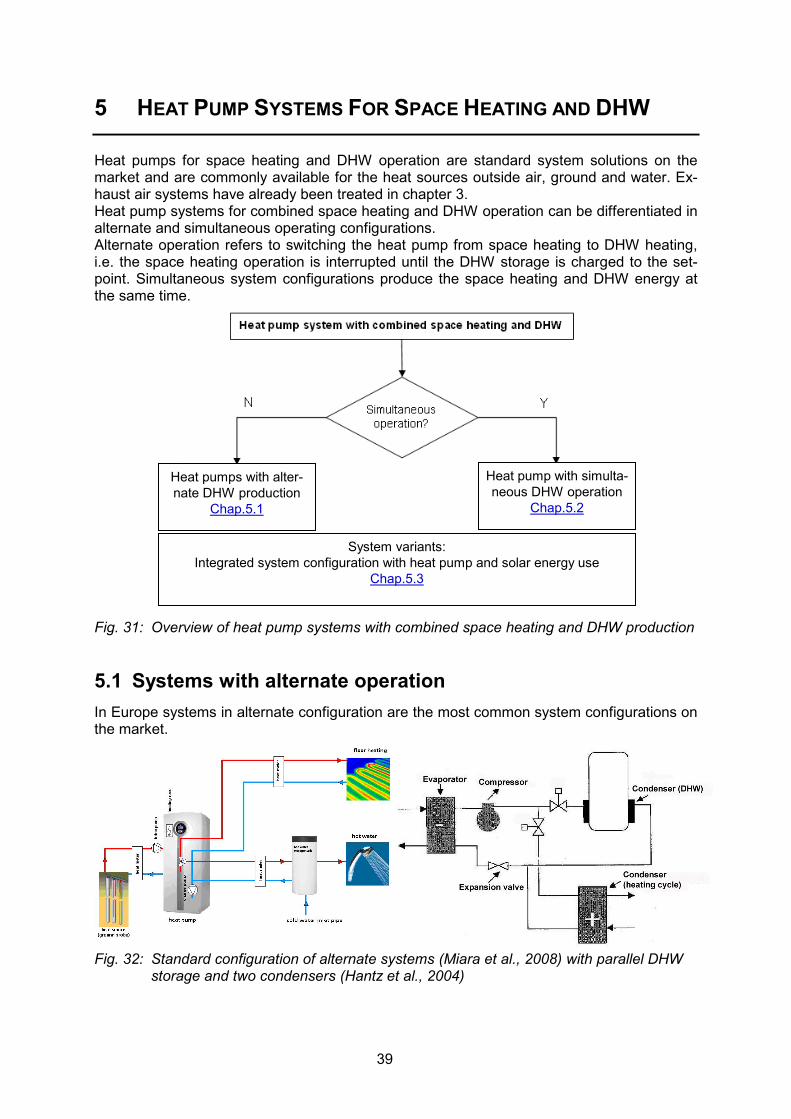
Heat pumps for space heating and DHW operation are standard system solutions on the market and are commonly available for the heat sources outside air, ground and water. Ex-haust air systems have already been treated in chapter 3. Heat pump systems for combined space heating and DHW operation can be differentiated in alternate and simultaneous operating configurations. Alternate operation refers to switching the heat pump from space heating to DHW heating, i.e. the space heating operation is interrupted until the DHW storage is charged to the set-point. Simultaneous system configurations produce the space heating and DHW energy at the same time.
Fig. 31: Overview of heat pump systems with combined space heating and DHW production
5.1 Systems with alternate operation In Europe systems in alternate configuration are the most common system configurations on the market.
Fig. 32: Standard configuration of alternate systems (Miara et al., 2008) with parallel DHW storage and two condensers (Hantz et al., 2004)
Heat pump with simulta-neous DHW operation
Chap.5.2
Heat pumps with alter-nate DHW production
Chap.5.1
System variants: Integrated system configuration with heat pump and solar energy use
Chap.5.3

40
This system configuration can be distinguished as well by the type of storage and the hy-draulic integration of the storage. Configurations found on the market include the following:
• Intermediate circuit with external refrigerant/water heat exchanger for the DHW circuit
• DHW water/water heat exchanger around the storage tank (mantle storage tank)
• Condenser of the refrigerant inside the storage tank or around the storage
• Combined storage: a smaller DHW storage is integrated in a bigger heating buffer storage
• Fresh water system: Buffer storage with external heat exchanger for instantaneous DHW production
Fig. 33: Direct storage integration with condenser in storage (based on EN 255-3:1997)
Fig. 34: Storage integration with intermediate cycle (based on EN 255-3:1997)
Fig. 35: Fresh water system (left, source: Zottl et al., 2010) and different types of combi-
storages (source: FAWA, 2004)

41
Fig. 33 shows the direct integration into the storage, Fig. 34 shows configuration with an in-termediate cycle. Fig. 35 left depicts an example of a fresh water system with buffer storage and instantane-ous water heating, which avoids problems with legionella. Fig. 35 right shows different types of combi storages for space heating and DHW operation.
5.2 Systems with simultaneous operation Most common marketable systems with simultaneous operation use a desuperheater for the simultaneous DHW production. Desuperheaters are common in North-American system configurations of air-to-air heat pump as shown in Fig. 36. The desuperheater is located on the outlet of the compressor and desuperheats the hot refrigerant down to the condensation temperature. The high tempera-ture level of the desuperheating is favourable for the DHW production. The condenser is used to provide the reheating of the recirculated air. In case of a system with reverse opera-tion the heat pump can also recool the recirculating air in summer operation. Note that the temperature level in the condenser defines the heat pump COP, while in alternate operation the higher temperature requirements of the DHW operation defines the COP of the heat pump.
Fig. 36: Canadian air-to-air heat pump with desuperheater for the DHW production (Minea 2003)
A problem with the desuperheater could be that it is only active in case of space heating or cooling load of the dwelling, so a back-up heating for the DHW mode may be required for the times without space heating or cooling load. Fig. 37 shows a Norwegian system configuration with simultaneous operation for space heating and DHW in monovalent configuration, which uses a desuperheater for the domestic hot water production both in summer and in winter operation. In winter operation the condenser which is located in the lower part of a storage works on the heating cycle while a desuperheater is used for the domestic hot water production in the upper part. In summer operation, the domestic hot water is preheated in the lower part of the storage by the condenser heat and re-heated by the desuperheater. In this way the desu-perheater can support the DHW production independent of the space heating energy needs. Moreover, cascade solutions, where the upper stage extracts heat from the cycle of the lower stage are possible. An example from Switzerland is given in Fig. 38.

42
Fig. 37: Norwegian simultaneous heat pump with desuperheater (Jakobsen, 2003)
Fig. 38: Swiss two stage simultaneous operating heat pump concept with condensate sub-
cooling of the lower stage heat pump for space heating Summarising, simultaneous operating systems may have several efficiency benefits com-pared to alternate operating system solutions: • Use of higher internal process temperatures as heat source (condensate subcooling). • Higher COP by lower condensation temperature also in DHW operation (desuperheater). • Better temperature match in a desuperheater, condenser or subcooler and thus reduced
exergy losses for the heat transfer. • Extended heat extraction from the process by use of subcooling heat as source or for
preheating purpose. • No interruption of the space heating operation during DHW production. • Heat recovery in combined space cooling/DHW operation.

43
5.3 Systems with integration of solar energy Presently, many systems combining heat pumps with solar thermal collectors are available on the European markets. But, since most of them were introduced recently, there is no ex-perience about functionality, performance and operational behaviour of such systems. Therefore, a new joint IEA SHC Task 44/HPP Annex 38 has started in Jan. 2010 and will continue for a 4-year period until the end of 2013. The objective is to investigate marketable and new combinations of heat pumps and solar thermal collectors to quantify the benefits of the combinations. The overview given in Tab. 5 is a first classification of marketable system integrating heat pumps and solar themal collectors for space heating and DHW and was out-lined in Henning and Miara (2008). In the table, also the main characteristics of the respec-tive hydraulic integration are given.
Tab. 5 Overview of integration of solar energy and heat pump (Henning and Miara, 2008) System integration options of heat pump and solar thermal collector system System sketch Short description
System with no interaction • Use of solar energy only for DHW • No direct interaction between systems • Contribution of solar energy to higher
overall SPF due to less DHW operation • No direct regeneration of the ground
Active regeneration • Use of solar energy for DHW and rege-
neration of the ground • Eventually reduced length of borehole
heat exchanger possible • Danger of drying-out of the ground • Seasonal storage with one borehole not
possible => Rather suited for borehole fields
• Higher solar contribution by elevation of source temperature possible
• Reduction of stagnation operation of the collector
Big buffer storage • Buffer storage as heat source for the heat
pump • Borehole heat exchanger as back-up • Charging of buffer and DHW by solar en-
ergy • Higher inlet temperature possible at high
solar irradiation level • No active regeneration of the ground

44
Maximum integration • Integration of solar energy and heat pump
by central stratified storage • Heat pump as back-up of the solar sys-
tem • Condenser of heat pump placed in stor-
age • DHW by fresh water system • No active regeneration of the ground
Unglazed collector • Unglazed collector as elevation of the
ground temperature • Cost advantages by unglazed collectors • Eventually reduction of borehole heat ex-
changer length possible • No solar contribution for DHW operation
Solar heating system • Special hybrid collector which uses solar
energy and the outside air • Hybrid collector connected to an ice stor-
age, which stores the heat in the phase change ice - water
• Ice-storage is heat source of the heat pump
• Solar contribution to the DHW production • No ground heat exchanger required
Outside air heat pump • Separate solar collector and air-to-water
heat pump (not integrated as hybrid col-lector)
• Heat pump uses solar source and outside air source
• Solar contribution to DHW production • No ground heat exchanger required

45
6 HEAT PUMP SYSTEMS WITH SINGLE FUNCTIONALITY
Heat pump systems with single functionality are the most common heat pumps on the mar-ket. In Europe heat pumps for space heating are the most common systems, in some coun-tries, heat pump water heaters have a considerable market share, as well. In particular in Japan, the market of the heat pump water heaters with CO2-refrigerant (so-called EcoCute systems) increased rapidly since their market introduction in the year 2000. In 2007 430.000 units were shipped, and the cumulated number in 2007 reached ~1'000'000 sold units (Ida, 2008). The target for 2010 is 5'200'000 sold units. Various systems of CO2-HPWH of differ-ent manufacturers are on the market now.
6.1 Space heating-only heat pumps System configurations can be distinguished by the integration of storages in the heating cy-cle and the number of heating cycles connected to the heat pump. The most common con-figurations and characteristics according to Gabathuler et. al. (2002) are given in Tab. 6.
Tab. 6 Overview of space heating-only heat pump systems (Gabathuler et. al., 2002) Standard systems for space heating-only heat pumps System sketch Short description
Systems without storage • easiest solution • preferable due to robustness and costs
Systems with serial storage • in the return of the heating cycle • required to augment thermal
capacity of the space heating cycle • prevention of cyclic operation of the
heat pump • mainly required in radiator systems
Systems with parallel storage • heating buffer storage in parallel • hydraulic decoupling of heat pump and
heat emission • useful, if more than one heating cycles
is connected

46
6.2 Heat pump water heaters 6.2.1 Conventional heat pump water heaters Common advanced designs of heat pump water heaters (HPWH) use up to four heat ex-changers in order to best fit the temperatures of the heated DHW. In a desuperheater, the higher discharge temperatures of the refrigerant at the compressor outlet are used for re-heating the DHW without increasing the condensation temperature. At the closest tempera-ture spread (pinch point) the condensation of the refrigerant starts and a subcooling of the refrigerant for preheating the DHW have efficiency gains for the expansion process. More-over, a suction gas heat exchanger can be used to transfer heat of the subcooled conden-sate to superheat the suction gas in order to increase desuperheating potential. Fig. 40 left shows the temperature difference in the heat exchangers for desuperheater, condenser and subcooler. Residential HPWHs in the US come in two basic types, separate (or add-on) and integral. The add-on type has a separate, small heat pump package which is connected to a conven-tional water heater tank via hoses. A pump is used to circulate water to/from the storage tank to the water-to-refrigerant condenser in the heat pump unit. The integral type features a small heat pump unit mounted atop a conventional storage tank. This type may use a pump to circulate tank water to the heat pump condenser or the condenser may be inserted di-rectly into the tank or wrapped around the tank exterior (Fig. 39).
Fig. 39: Integral HPWH with wrapped tank condenser (source: Baxter, 2009)

47
6.2.2 CO2 heat pump water heaters (EcoCute systems) Heat pumps with carbon dioxide (CO2, R744) refrigerant are a new and promising technology in particular for DHW heat pump water heaters (HPWH). CO2 is a non-flammable and non-toxic fluid with a global warming potential (GWP) = 1 when used as refrigerant, in contrast to common HFC refrigerants. Due to the low critical temperature of 31.1 °C, a so-called trans-critical cycle is used for CO2 heat pumps, where the heat is rejected by cooling down the su-perheated CO2 in a single counter-flow gas cooler, see Fig. 40 right. Fig. 40: Desuperheater-condenser-subcooler configuration used in common heat pump wa-
ter heaters (right) and heating-up of DHW in counterflow gas cooler with super-heated CO2-refrigerant (left)(source: Stene, 2008)
Since the temperature fit reflects the exergy losses of the heat transfer, it becomes clear that the cooling of the CO2 refrigerant in a counter-flow heat exchanger has exergetic benefits compared to the condensation at nearly constant temperature of other refrigerants. Thus, a higher COP for the DHW application can be expected, although very high DHW outlet tem-peratures of 60-85°C are reached. The domestic hot water use in Japan is quite high compared to Europe due the tradition of taking a hot bath every evening. Therefore, the domestic hot water is stored at quite high temperatures. In particular for the applications of hot water at high temperature levels, CO2-heat pumps have performance advantages compared other refrigerants. In Japan, DHW is normally produced during night-time, since the electricity tariff during nighttime is only ¼ of the daytime tariff. Fig. 41 shows a common configuration of Japanese Eco Cute systems which usually uses the outside air as heat source. Units in the capacity range of 4-20 kW are on the market. Fig. 41 shows the outdoor unit and the DHW tank which is inside the white box.
Fig. 41: CO2-heat pump water heater on the Japanese market (called EcoCute systems)

48

49
7 CONCLUSIONS
The report gives an overview of marketable system configurations for the use in low energy houses. Due to the different energy needs, adapted system solutions have partly already been developed or are currently under development. Compared to conventional new buildings in particular ventilation air based system solutions and integrated systems were developed, starting with integrated system for German passive houses. However, capacity of some marketable systems is also suitable for the application in low energy houses. Integrated systems mainly comprise the functions space heating, DHW and ventilation. The report gives a categorisation which based on the integrated functionality of the systems. Mainly ventilation air based system solutions, system with cooling function independent of the ventilation and combined space heating and DHW functions can be distinguished. Current heat pump market trends are driven by three issues: system integration, capacity control and natural refrigerants. In Europe heat pumps show a strong increase in some na-tional markets (EHPA, 2009). On the one hand system integration is related to the combination of heat pump with solar thermal collectors. Many manufacturers provide systems with heat pump and solar thermal collectors of different degree of integration. However, there is little information about the seasonal performance of these systems and whether higher investment costs are justified, since the heat pump and the solar collector performance may be in competition, e.g. if en-ergy is covered by the solar collector in times of good heat pump performance. Therefore, these combinations are investigated in a joined IEA SHC Task 44/HPP Annex 38. On the other hand system integration is related to the extension of the system configuration to the integration of the ventilation system or with a space cooling option. More and more manufacturers have integrated options for passive ground-coupled cooling in their system configurations in the recent years. Moreover, Japanese companies like Daikin and Mitsubishi are expanding into the European residential market with system concepts based on heat pump air conditioners as used in Ja-pan. These units often have a space heating and space cooling operation mode, are nor-mally inverter-controlled and are presently adapted to common emission systems on the European market like floor heating, leading to an increasing number of capacity-controlled heat pumps. Capacity controlled units may have advantages in part load conditions due to lower flow temperature and better COP in part load operation, and systems can be operated down to very low temperatures of – 20°C. This could be interesting for monovalent design and for the application in Nordic countries. Last but not least, there is an ongoing discussion to phase-out the HFC refrigerants in Europe, and manufacturers are actively investigating options with natural refrigerants like CO2 or propane. However, only a few manufactures offer heat pumps with natural refriger-ants on the European market, while most of the systems use HFC refrigerants.

50

51
8 ACKNOWLEDGEMENT
The operating agent as editor of this report is very grateful for the valuable contributions of all participants of the IEA HPP Annex 32 and for the constructive discussion and co-operation. It has to be emphasised that the Annex 32 is a co-operative research project and results are taken from national contributions. The operating agent would like to thank the Swiss Office of Energy (SFOE) for funding and supporting the project, in particular the research programme manager Prof. Dr. Thomas Kopp for advising in the Annex 32 project and the Swiss national project within the Annex 32.

52

53
9 REFERENCES
Baxter V.D. (2009). Comments on draft report, ORNL, Tennessee, December, US Dott, R., Afjei, T., Huber, A. (2007), Heizen und Kühlen mit erdgekoppelten Wärmepumpen,
Final report Swiss Federal Office of Energy, Muttenz, CH. EN 255-3 (1997) Air conditioners, liquid chilling packages and heat pumps with electrically
driven compressors - Heating mode - Part 3: Testing and requirements for marking for sanitary hot water units (includes corrigendum AC:1997); July, EU
EPBD (2003) Directive 2002/91/EC on the Energy Performance of Buildings (EPBD), Euro-pean Council, 4.1.2003, Brussels, EU
EHPA (2009) Outlook 2009. European Heat pump statistics, European Heat Pump Associa-tion, Brussels, EU
Eschmann, M. (2009). Monitoring von Klein-Wärmepumpen mittels Normprüfungen 2008, Final report of SFOE research project, Buchs, February, CH
Fehrm, M. (2005), The exhaust air heat pump – a rational way for heating low energy houses, Proceedings 8th International heat pump conference, Las Vegas, US, May 30 – June 2, SE
Gabathuler, H.R., Mayer H., Afjei, Th. (2002) Standardschaltungen für Kleinwärmepumpen-anlagen, Teil 1: STASCH-Planungshilfen, Final report SFOE research project, Muttenz 2002, CH
Hantz, D., Colomines, F. (2003) French country report Annex 28, Task 1, Lyon, October, FR Henning, H.M., Miara M. (2008) Systems using solar thermal energy in combination with
heat pump,1st concept paper Solar Heating and Cooling, Freiburg/Brsg., November, DE
Heinz, A., Mach, Th., Rieberer, R. (2007). Economical heating and cooling systems for low energy houses, Task 1: State-of-the art analysis, Country report Austria, TU Graz, Ju-ly, AT
Ida, H. (2010) Overview of the climate, the energy-saving policy and heat pump systems in moderate climate zone of Japan, Report Tokyo Electric Power Company, April 2010, JP
Ida, H., Takeda-Kindaichi, S. (2008), Presentation Workshop Annex 32, 9th IEA Heat Pump Conference, Zurich, JP
Jakobsen, A. (2003): Country report IEA HPP Annex 28 Task 1 Norway, Trondheim, October, NO
Karlsson, F., Lidbom, P., Axell, M., Lindberg, U. (2006). Air-to-Air Heat Pumps Evaluated for Nordic Circumstances. Heat Pump Centre Newsletter, Volume 24, No. 4/2006, pp. 18-24.
Kriesi, R., Schnyder, P., Frei, B. (2006). Der Enthalpie-Plattentauscher Comfohygro - zur weiteren Verbesserung des Komforts im Innenraum, 14. Schweizerischen Status-Seminar Energie- und Umweltforschung im Bauwesen, pp. 179 - 184, 7./8. September 2006, Zürich
Lamanna, B. (2010). Inverter and programmable controls in heat pump applications, Presen-tation 3rd EHPA European Heat Pump Forum 20.05.2010, Brussels, EU
Minea, V. (2003), North American Test procedures and calculations for residential for resi-dential heat pumps with combined space and hot water heating, Country report IEA HPP Annex 28 Task 1 Canada, November, Shawinigan, CA
MINERGIE® (2006), Standard Lüftungssysteme, download at http://www.minergie.ch

54
NOVAP (2007), Information of the Norwegian Heat Pump Association (NOVAP), http://www.novap.ch
Recknagel, Sprenger, Schramek (2005): Taschenbuch für Heizung+Klimatechnik 05/06, 72. Auflage, Oldenbourg Industrieverlag, München, 2005
Stene, J. (2007) IEA HPP Annex 32 - Economical Heating and Cooling Systems, State-of-the-Art Report Norway, SINTEF Technical Report TR – A6506-07, Sintef Energy Re-seach, Trondheim, April, NO
Stene, J. (2008) IEA HPP Annex 32 – 1) Analysis of CO2 heat pump system for low-energy and passive houses, 2) Field testing of an integrated propane heat pump system in a passive house, SINTEF Technical report TR A6676, Trondheim, May, NO
WWF (2009) Klimaschutz spart Geld beim Wohnen - Was sich für Hausbesitzer bei der Ge-bäudehülle und Heizsystemwahl schon heute lohnt, World Wildlife Fund Schweiz, Zü-rich, CH
Zottl, A., Köfinger, Ch., Huber, H. (2010). Field monitoring of integrated heat pump systems - Field measurements of 11 heat pump systems, Final country report Austria IEA HPP Annex 32 Task 3, Austrian Institute of Technology, Vienna, July, AT

55
10 APPENDIX
• A: Market Overview of heating centrals, compact units, exhaust air heat pumps in
AT, CH, DE • B: Overview of recent Japanese mini split units • C: Summary of characteristics of common heat pumps

56
A MARKET OVERVIEW ON HEAT PUMP COMPACT UNITS
Tab. A 1 Market overview heating centrals with Ventilation Heat Recovery and heat pump without heat recovery by of the exhaust air
Manufacturer Drexel & Weiss Kennelbacherstr. 36 A-6900 Bregenz
drexel-weiss.at
Friap AG Ey 9 CH-3063 Ittingen friap.ch
Zehnder Comfortsystems Industriestr. CH-8820 Wädens-wil comfosystems.ch
Alpha-Innotec Logistikcenter Gäuerhof CH 6246 Altishofen
calmotherm.ch
Siemens/Novelan AG Bucherstrasse 31 CH-8108 Dällikon novelan.ch
Type Aerosmart XSL Friap FM 3/FM 6 Comfobox KHZ LW 60/80 (Calmotherm) HLW 6M/8M (Novelan)
Figure
Application LEH, PH LEH LEH LEH LEH
Funktionality VHR, SH, DHW VHR, SH,DHW, SC (o), Sol (o)
VHR, DHW, SH, SC (o)
VHR, SH, DHW VHR, SH, DHW
Capacity WP [kW] 2.5 (B0/W35) 3 or 6 (A2/B0/W35) 5-10 or 6-10 6 or 8 (A2/W35) 6 or 8 (A2/W35)
El. back-up heater [kW] 2 (WW) 2 (WW) 2 6 6
Heat source S (hor.) OA or S OA or S OA OA
Abgabesystem W W W W W
Volume flow rate [m3/h] 160-230 150 – 500 45 - 500 50-300 50-300
Storage size [l] 200 external 400/500 l 265 l 265 l
DHW-Temperature [°C] n.a. Bis 67 54 (60 EH) ~48 ~48
Refrigerant R134a R407C R134a/R410C R404a R404a
Legend: LEH –low energy house, PH – Passive house, VHR – ventilation heat recovery, SH – space heating, SC – space cooling, Sol – Solar collector, o – optional, OA – outdoor air, W – PWW, blue backgruond – cooling option, B – Brine, n.a. – not available, DHW – Domestic hot water, hor. – horizontal ground collector

57
Tab. A 2 Market overview of ventilation compact units with heat recovery and exhaust air heat pump for space heating and/or DHW production Manufacturer
Dre
xel &
Wei
ss
Ken
nelb
ache
rstr.
36
A-6
900
Bre
genz
w
ww
.dre
xel-w
eiss
.at
AE
RE
X H
T-S
yste
me
Gm
bH
Ste
inki
rchr
ing
27
7805
6 V
illin
gen-
Sch
w.
ww
w.a
erex
.de
Stie
bel-E
ltron
AG
N
etzi
bode
nstr.
23c
C
H-4
133
Pra
tteln
w
ww
.stie
bel-e
ltron
.ch
Sie
men
s/N
ovel
an A
G
Buc
hers
trass
e 31
C
H-8
108
Däl
likon
w
ww
.nov
elan
.ch
Sie
men
s/N
ovel
an A
G
Buc
hers
trass
e 31
C
H-8
108
Däl
likon
w
ww
.nov
elan
.ch
Bau
-Info
-Cen
ter (
BIC
) P
ostfa
ch 2
6 D
-725
30 H
ohen
stei
n w
ww
.bau
info
cent
rer.d
e
Bau
-Info
-Cen
ter (
BIC
) P
ostfa
ch 2
6 D
-725
30 H
ohen
stei
n w
ww
.bau
info
cent
rer.d
e
NIL
AN
AG
S
chüt
zens
trass
e 33
C
H-8
902
Urd
orf
Tel:
+41-
44 7
36 5
0 00
Fa
x: +
41-4
4 73
6 50
09
ww
w.n
ilan.
ch
Effi
zien
to H
aust
echn
ik
Gm
bH
Lang
wie
sens
tr. 8
D
-743
63 G
üglin
gen
ww
w.e
ffizi
ento
.com
Type Aerosmart S-L, mono
Aerex BW 175
LWZ 303 SOL THZ 303SOL
Genvex Combi 185 L
GE VP(C) Serie
WRG134 BP
WRG134LW WRG334LW
VP 18-10 P Effiziento
Figure
Application U U L U U U U U L
Functionality VHR, SH, DHW
VHR, SH DHW, Sol (o)
VHR, SH, DHW, Sol (o)
VHR, SH, DHW, SC (o), Sol (o)
VHR, SH, SC (VPC)
VHR, SH VHR, SH (s), DHW, SC (o)
VHR, SH, DHW, SC(o), Sol (o)
VHR, DHW, SH, Sol (o)
Capacity HP [kW] 1.0(S)-1.7(L)
1.4 4.2 1.4 1.4 1.4 1.4 1.3 4
El. BU [kW] 2 (DHW) 2 (DHW) 6 1 none none none 1 2(-6 (o))
Heat source EA EA Mix OA/EA EA EA EA EA EA OA/EA
Heat sink A A W A, W(o) A A A A, W (o) W, A(o)
Air flow [m3/h] 105-230 140-210 80-230 (VHR) max. 260 100-260 80-250 100-265 75-240 70-350 (VHR)
Storage size [l] 200 Extern 320 200 185 none none External 180 External 500
DHW temp. [°C] n.a. n.a. 55 55 n.a. none n.a. 65 55
Refrigerant R134a R134a R407C R134a R407C R134a R134a R134a R407C
Legend: L – low energy, U – ultra low energy house, VHR – Ventilation heat recovery, SH –space heating, SC – space cooling, Sol - solar collector, a – additional, o – optional, s –supplementary, EA - exhaust air, OA - outside air, W – water blue background – space cooling option

58
Tab. A 3 Market overview of exhaust air heat pumps (without a ventilation heat recovery) for space heating and/or DHW production Manufacturer
Stie
bel-E
ltron
AG
N
etzi
bode
nstr.
23c
C
H-4
133
Pra
tteln
w
ww
.stie
bel-e
ltron
.ch
Stie
bel-E
ltron
AG
N
etzi
bode
nstr.
23c
C
H-4
133
Pra
tteln
w
ww
.stie
bel-e
ltron
.ch
AE
RE
X H
T-S
yste
me
Gm
bH
Ste
inki
rchr
ing
27
7805
6 V
illin
gen-
Sch
w.
ww
w.a
erex
.de
NIL
AN
AG
S
chüt
zens
trass
e 33
C
H-8
902
Urd
orf
Tel:
+41-
44 7
36 5
0 00
Fa
x: +
41-4
4 73
6 50
09
ww
w.n
ilan.
ch
NIL
AN
AG
S
chüt
zens
trass
e 33
C
H-8
902
Urd
orf
Tel:
+41-
44 7
36 5
0 00
Fa
x: +
41-4
4 73
6 50
09
ww
w.n
ilan.
ch
NIL
AN
AG
S
chüt
zens
trass
e 33
C
H-8
902
Urd
orf
Tel:
+41-
44 7
36 5
0 00
Fa
x: +
41-4
4 73
6 50
09
ww
w.n
ilan.
ch
Sie
men
s/N
ovel
an A
G
Buc
hers
trass
e 31
C
H-8
108
Däl
likon
w
ww
.nov
elan
.ch
Type LWA 100 LWA 203/303 SOL (AEREX TWIN Boxx)
VP 18 VGU 250 (EK 6/9) VPL 15 EC Vanvex 185 S/ 285 S
Figure
Application U, L (with s) U, L (with s) U U U U Functionality V, DHW V, SH, DHW, Sol (o) VHR, DHW, SH, SC
(o), Sol (o) V, DHW, SH (EK) V, SH, SC V, DHW, Sol (o)
Capacity HP
0.8 1.5 2.1 1.2, 2.1 (EK) 2.1 1.5
El. BU [kW] 3 6.6 (DHW) 1 (o) 1, 9 (EK) none 1 Heat source EA EA EA EA EA EA ; OA (a) Heat sink DHW DHW, W DHW, A, W (o) DHW, W (EK) A DHW Air flow rate
50-130 70-290, min. HP 120 max. 330 325 100 - 400 max. 280
Storage size [l] 100 300 180 230 none 185/285 DHW temp.
max. 55 (HP) max. 60 (HP) 60 60 none 55
Refrigerant R290 R134a R134a n.a. R134a R134a Legend: L – low energy, U – ultra low energy house, V – Ventilation, SH –space heating, SC – space cooling, Sol - solar collector, o – optional, s –supplementary,
EA - exhaust air, OA - outside air, W – water HP – heat pump blue background – space cooling option, a – alternate, min- minimum, max - maximum

59
B MARKET OVERVIEW ON RECENT MINI SPLIT UNITS
In the Japanese country report recent developments for marketable Mini Split Units of differ-ent manufacturers are outlined in the following overview.

60

61

62

63
C

64

65
C SUMMARY OF COMMON HEAT PUMP TYPES
C.1 Air-to-Air Heat Pumps – Summary Heat source • Ambient air – large variations in average temperature and DOT1 in Norway
Heat pump unit – components and design
• Heat pump system with one outdoor unit (evaporator, fan, compressor, expan-sion valve etc.) and one or several indoor units (condenser, fan etc.). The units are connected with flexible hoses (single or multisplit units).
Heating demands • Space heating – Covered by the heat pump + possible auxiliary heating system • Heating of ventilation air – Reheating covered by the space heating system • DHW heating – Covered by a separate heating system
Heat distribution • Air – recirculation and heating of indoor air by the indoor unit(s). Moderate sup-ply air temperature (max. 30-35ºC)
• Requires open floor plan in the residence in order to achieve satisfactory distri-bution of the warm air from the indoor unit
• Bathroom and washing areas should have separate heating systems (floor heating)
Cooling demands
• Recirculation and cooling of indoor air by the indoor units. The heat pump runs in “reverse mode” which requires electricity, i.e. no free cooling.
Ventilation • Can be used in residences with exhaust air ventilation or balanced ventilation
Design/ dimensioning
• The heat pump unit should be designed/dimensioned to cover the entire heat load (100 % coverage) for space heating in low-energy and passive houses
Average COP (SPF)
• Average COP in Norway ranges from 2.0 to 3.0, defrosting included • Considerable variations in quality and performance for the different air-to-air-
heat pump brands/models. R410A heat pumps with inverter controlled com-pressor achieve the highest COP.
• Some models have poor defrosting systems without demand control
Indoor environment
• Heating of indoor air with moderate excess temperature in the exhaust zone. • Provides good thermal comfort in low-energy houses since windows and walls
have low U-values (i.e. no large temperature gradients or drafts). • Heating of indoor air will lead to drier air which may irritate allergic persons. • The indoor unit is equipped with different filter types (synthetic fibre, zeolit, car-
bon, electrostatic), that clean the recirculated air. However, the fans may whirl up dust.
• The fan of the indoor unit generates noise, typically 49-58 dB(A).
Miscellaneous • The stop temperature ranges from -10 to -25ºC (ambient air temperature). • The evaporator in the outdoor unit must be regularly defrosted at ambient air
temperatures below approx. +3ºC – requires energy and reduces the COP. • Requires correct installation of the indoor/outdoor units. • Requires regularly cleaning/replacement of the filter(s) in the indoor unit. • The compressor/fan in the outdoor unit generates noise, typically 58-63 dB(A).
Areas of applica-tion
• Low-energy houses – Air-to-air heat pumps applicable in all types of dwellings • Passive houses – Air-to-air heat pumps can be used in large residences, but
will not be profitable in flats due to the very low space heating demand
1 Design Outdoor Temperature

66
C.2 Exhaust Air – Ventilation Air Heat Pumps – Summary Heat source • Exhaust air, possibly in combination with ground (indirect system with a
brine circuit connected to an air cooler and a ground-source heat ex-changer).
Classification/design • Heat pump water heater (HPWH, Type A1) – Compact heat pump unit with air cooled evaporator. Heat rejection to a hot water tank (direct or indirect system design). Reheating by electric immersion heaters, see chap. 3.3.
• Integrated units (Type A2)– Compact heat pump unit with air cooled evapo-rator. Heat rejection to a hot water tank (direct or indirect design) and hy-dronic heat distribution system for space heating (floor heating, fan convec-tors etc.). Electric immersion heaters used for supplementary heating (peak load), see chap. 3.4
• Integrated units (Type A3) – Compact heat pump unit with air cooled evapo-rator with additional heat source, e.g. the ground acc. to Fig. 2.
Heating • Space heating – Partly covered by the heat pump (Type A2, Type A3).
• Heating of ventilation air – Covered by the space heating system.
• Hot water heating – Covered by the heat pump. Reheating with electric im-mersion heaters located in the hot water tank (Type A2, Type A3).
Cooling • The heat pumps cannot provide space cooling
Heat distribution • Hot water – connection to single-shell or double-shell hot water tank.
• Hydronic heat distribution system with floor or ceiling heating, fan convec-tors, heating boards or radiators (see Tab. 2).
Ventilation • Used in dwellings with an exhaust air ventilation system
Dimensioning • HPWH (Type A1) – Designed to cover the entire heating demand.
• Integrated (Type A2, Type A3) – Designed to cool down the exhaust air to minimum 2-3ºC. Covers the entire hot water demand. The systems are nor-mally not capable of covering the entire space heating demand due to lim-ited energy content in the exhaust air. Supplementary heating (peak load) with electric immersion heaters.
Average COP (SPF) • Hot water heating – COP typically 2.5.
• Space heating – COP typically 3.5 (requires low-temperature system).
Indoor environment • Space heating with hydronic heating system. Air quality and thermal comfort is affected by the type of system (floor heating, fan convectors etc.).
Miscellaneous • The relatively constant operating conditions and moderate temperature lift for the heat pump unit is favourable with regard to expected lifetime etc.
• Compressor breakdown for propane heat pumps from some Swedish manu-facturers, but the problems have been resolved.
• Due to limited energy content in the exhaust air, integrated heat pumps are only capable of covering a part of the space heating demand, which means that the energy demand for supplementary heating can be relatively high.
Areas of application The recommendations are based on the calculations of total annual specific en-ergy demand for heating of a 150 m2 low-energy house.
• Low-energy houses – Type A1 in combination with air-to-air heat pump for space heating, (integrated system) and Type A3 (as chap. 3.4 + ground as additional heat source) are of current interest.
• Passive houses – Only Type A1 is of current interest.

67
C.3 Balanced Ventilation Air Heat Pumps – Summary Heat source • Exhaust air, discharge air (passive house only) or a mixture of discharge air
and ambient air. The ambient air can be preheated by a ground heat ex-changer.
Design • Ventilation air heat pumps without heat recovery unit (System B1, see chap. 3.5) – Units with air-cooled evaporator in the exhaust ventilation duct. Heat rejection to the supply ventilation air (direct system). Reheating by electric heater.
• Integrated heat pump without heat recovery unit (System B2, see chap. 3.5) – Units with air cooled evaporator in the exhaust ventilation duct. Heat re-jection to a hot water tank and the supply ventilation air. Auxiliary heating with electric heaters.
• Integrated heat pump with heat recovery unit (System B3, see chap. 3.6.2) – Compact units with ventilation unit (fans, filters, heat exchanger), air-to-air/water heat pump unit, hot water tank and solar collector. Auxiliary heat-ing with electric heaters.
Heating • Space heating – Partly covered by the heat pump (Type B1, B2 and B3)
• Heating of ventilation air – Covered by the heat pump (Type B1, B2 and B3)
• Hot water heating – Covered by the heat pump (Type B1, B2, and B3). Re-heating with electric immersion heaters located in the hot water tank.
Cooling • Some of the heat pump systems are designed for space cooling
Heat distribution • Hot water – connection to single- or double-shell hot water tank
• Space heating by warm ventilation air (direct system) or by means of a hy-dronic heat distribution system (indirect system)
• Ventilation air – direct or indirect heat system
Ventilation • Used in dwellings with a balanced ventilation system
Dimensioning • Ventilation air heat pump (System B1) – Cools down the exhaust air to minimum 2-3ºC. Do not cover hot water heating.
• Integrated heat pump (System B2) – Cools down the exhaust air to mini-mum 2-3ºC. Covers the entire heating demand for hot water.
• Compact unit (System B3) – Designed according to the available energy in the heat source. Covers the entire heating demand for hot water.
Average COP (SPF) • Hot water heating – COP typically 2.5
• Space heating – COP typically 2.0-3.5 (depending on different factors)
Indoor environment • Space heating with hot supply air (max. 50-55ºC) or hydronic heat distribu-tion system. Hot ventilation air can lead to bad ventilation efficiency and poor indoor air quality.
• A horizontal ground heat exchanger (GHE) for preheating of the ambient air may lead to poor indoor air quality due to bacterial growth in GHE.
Application of ventila-tion air heat pumps – balanced ventilation systems
The recommendations are based on the calculations of total annual specific en-ergy demand for heating of a 150 m2 low-energy house.
• Low-energy houses – Type B1 (heating of ventilation air), Type B2 (inte-grated unit, as A2) and integrated systems acc. to Fig. 2 (compact unit) are of current interest.
• Passive houses – Type B3 is of current interest.
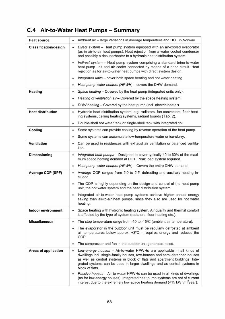
68
C.4 Air-to-Water Heat Pumps – Summary Heat source • Ambient air – large variations in average temperature and DOT in Norway
Classification/design • Direct system – Heat pump system equipped with an air-cooled evaporator (as in air-to-air heat pumps). Heat rejection from a water cooled condenser and possibly a desuperheater to a hydronic heat distribution system.
• Indirect system – Heat pump system comprising a standard brine-to-water heat pump unit and air cooler connected by means of a brine circuit. Heat rejection as for air-to-water heat pumps with direct system design.
• Integrated units – cover both space heating and hot water heating.
• Heat pump water heaters (HPWH) – covers the DHW demand.
Heating • Space heating – Covered by the heat pump (integrated units only).
• Heating of ventilation air – Covered by the space heating system.
• DHW heating – Covered by the heat pump (incl. electric heater).
Heat distribution • Hydronic heat distribution system, e.g. radiators, fan convectors, floor heat-ing systems, ceiling heating systems, radiant boards (Tab. 2).
• Double-shell hot water tank or single-shell tank with integrated coil.
Cooling • Some systems can provide cooling by reverse operation of the heat pump.
• Some systems can accumulate low-temperature water or ice-slurry.
Ventilation • Can be used in residences with exhaust air ventilation or balanced ventila-tion.
Dimensioning • Integrated heat pumps – Designed to cover typically 40 to 60% of the maxi-mum space heating demand at DOT. Peak load system required.
• Heat pump water heaters (HPWH) – Covers the entire DHW demand.
Average COP (SPF) • Average COP ranges from 2.0 to 2.5, defrosting and auxiliary heating in-cluded.
• The COP is highly depending on the design and control of the heat pump unit, the hot water system and the heat distribution system.
• Integrated air-to-water heat pump systems achieve higher annual energy saving than air-to-air heat pumps, since they also are used for hot water heating.
Indoor environment • Space heating with hydronic heating system. Air quality and thermal comfort is affected by the type of system (radiators, floor heating etc.).
Miscellaneous • The stop temperature range from -10 to -15ºC (ambient air temperature).
• The evaporator in the outdoor unit must be regularly defrosted at ambient air temperatures below approx. +3ºC – requires energy and reduces the COP.
• The compressor and fan in the outdoor unit generates noise.
Areas of application • Low-energy houses – Air-to-water HPWHs are applicable in all kinds of dwellings incl. single-family houses, row-houses and semi-detached houses as well as central systems in block of flats and apartment buildings. Inte-grated systems can be used in larger dwellings and as central systems in block of flats.
• Passive houses – Air-to-water HPWHs can be used in all kinds of dwellings (as for low-energy houses). Integrated heat pump systems are not of current interest due to the extremely low space heating demand (<15 kWh/m2year).

69
C.5 Brine- and Water-to-Water Heat Pumps – Summary Heat source • Brine-to-water – bedrock, soil, lake water (indirect system design).
• Water-to-water – groundwater, grey water (direct system design).
Components, design • Compact heat pump units equipped with plate heat exchangers as evaporator and condenser, and scroll or reciprocating compressor with variable speed or intermittent operation (on/off). Some units have integrated hot water tank, elec-tric heater for supplementary heating, pumps, expansion tank etc. Indirect sys-tems have a brine circuit (PEM tubes, antifreeze fluid, pump) that transfers heat between the heat source and the evaporator.
Heating • Space heating – Covered by the heat pump (integrated units only).
• Heating of ventilation air – Covered by the space heating system.
• DHW heating – Covered by the heat pump (electric heater incl.).
Heat distribution • Hydronic heat distribution system, e.g. radiators, fan convectors, floor heating systems, ceiling heating systems, radiant boards (Tab. 2).
• Double-shell hot water tank or single-shell tank with integrated coil.
Cooling • Heat pump units connected to boreholes in bedrock can provide free cooling where surplus heat from the house is rejected directly to the ground.
Ventilation • Can be used in residences with exhaust air ventilation or balanced ventilation.
Dimensioning • Integrated heat pumps – Designed to cover 40 to 60 % of the maximum space heating demand at DOT. Peak load system required.
• Heat pump water heaters (HPWH) – Covers the entire DHW demand.
Average COP (SPF) • Average COP ranges from 2.5 to 3.5, supplementary heating included.
• The COP is highly depending on the design and control of the heat pump unit, hot water system and heat distribution system.
Indoor environment • Space heating with hydronic heating system. Air quality and thermal comfort is affected by the type of system (radiators, floor heating etc.).
Miscellaneous • Quality gap between the various heat pump systems on the market.
• Important with correct design and operation of the entire heat pump system, i.e. heat source system, heat pump unit, hot water system and heat distribution system, in order to attain high energy efficiency.
• Ground-source systems have higher operational reliability and longer lifetime than ambient air heat pumps due to more stable operating conditions.
Areas of application • Low-energy houses – Brine-to-water HPWHs can be used in all kinds of dwell-ings including single-family houses, row-houses and semi-detached houses as well as central systems in block of flats and apartment buildings. Integrated heat pump systems can be used in larger dwellings and as central systems in block of flats etc.
• Passive houses – Brine-to-water HPWHs can be used in all kinds of dwellings (as for low-energy houses). Integrated heat pump systems are not of current in-terest due to the extremely low space heating demand (<15 kWh/m2year).
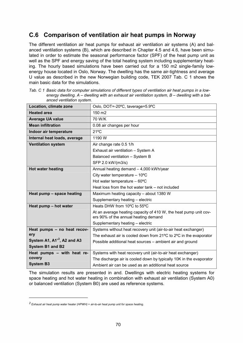
70
C.6 Comparison of ventilation air heat pumps in Norway The different ventilation air heat pumps for exhaust air ventilation air systems (A) and bal-anced ventilation systems (B), which are described in Chapter 4.5 and 4.6, have been simu-lated in order to estimate the seasonal performance factor (SPF) of the heat pump unit as well as the SPF and energy saving of the total heating system including supplementary heat-ing. The hourly based simulations have been carried out for a 150 m2 single-family low-energy house located in Oslo, Norway. The dwelling has the same air-tightness and average U value as described in the new Norwegian building code, TEK 2007 Tab. C 1 shows the main basic data for the simulations.
Tab. C 1 Basic data for computer simulations of different types of ventilation air heat pumps in a low-energy dwelling. A – dwelling with an exhaust air ventilation system, B – dwelling with a bal-anced ventilation system.
Location, climate zone Oslo, DOT=-20ºC, taverage=5.9ºC Heated area 150 m2 Average UA value 70 W/K Mean infiltration 0.08 air changes per hour Indoor air temperature 21ºC Internal heat loads, average 1190 W Ventilation system Air change rate 0.5 1/h
Exhaust air ventilation – System A Balanced ventilation – System B SFP 2.0 kW/(m3/s)
Hot water heating Annual heating demand – 4,000 kWh/year City water temperature – 10ºC Hot water temperature – 60ºC Heat loss from the hot water tank – not included
Heat pump – space heating Maximum heating capacity – about 1380 W Supplementary heating – electric
Heat pump – hot water Heats DHW from 10ºC to 55ºC At an average heating capacity of 410 W, the heat pump unit cov-ers 90% of the annual heating demand Supplementary heating – electric
Heat pumps – no heat recov-ery System A1, A1’2, A2 and A3 System B1 and B2
Systems without heat recovery unit (air-to-air heat exchanger) The exhaust air is cooled down from 21ºC to 2ºC in the evaporator Possible additional heat sources – ambient air and ground
Heat pumps – with heat re-covery System B3
Systems with heat recovery unit (air-to-air heat exchanger) The discharge air is cooled down by typically 10K in the evaporator Ambient air can be used as an additional heat source
The simulation results are presented in and. Dwellings with electric heating systems for space heating and hot water heating in combination with exhaust air ventilation (System A0) or balanced ventilation (System B0) are used as reference systems.
2 Exhaust air heat pump water heater (HPWH) + air-to-air heat pump unit for space heating.

71
Tab. C 2 Specific energy demand for heating of a 150 m2 low-energy house with different heat pump/ heating systems and ventilation systems. DHW – heating of domestic hot water, SH – space heating, VA – heating of ventilation air, HP – heat pump, HRU – heat recovery unit.
Type Heating and ventilation system Total heating demand1)
[kWh/year]
Heat supply from HP
[%]
COP, heat-ing system2)
[-]
Spec. energy demand2)
[kWh/m2year]
A0 Electric heating (DHW + VA + SH) Exhaust air ventilation – no HRU
12,600 0 1.0 84
A1 Ventilation air HP (DHW) Exhaust air ventilation – no HRU
12,600 29 1.2 70
A1’ Ventilation air HP (DHW) + Ambient air-to-air HP (SH) Exhaust air ventilation – no HRU
12,600 97 2.4 35
A2 Ventilation air HP (DHW+SH) Exhaust air ventilation – no HRU
12,600 78 2.1 40
A3 Vent. air + ground HP (DHW+SH) Exhaust air ventilation – no HRU
12,600 94 2.5 33
B0 Electric heating (DHW+VA+SH) Balanced ventilation – 75% HRU
7,700 0 1.0 51
B1 Ventilation air HP (VA+SH) Balanced ventilation – no HRU
12,600 57 1.7 50
B2 Ventilation air HP (DHW+VA+SH) Balanced ventilation – no HRU
12,600 78 2.1 40
B3 Compact unit (DHW + VA + SH) Balanced ventilation – 75% HRU
7,700 90 2.2 24
1) Includes heat recovery in the ventilation system 2) Includes energy demand for the auxiliary (peak load) heating sys-tem(s)
Fig. C 1 Specific energy demand for heating of a 150 m2 single-family low-energy house with different
heat pump/heating systems and heat recovery systems (A0 to A3 and B0 to B3).

72
In , “Total Heating Demand” is calculated as the gross annual heating demand (i.e. space heating, heating of ventilation air and hot water heating) subtracted the annual heat supply from internal loads, i.e. lighting systems, electrical appliances, fans, people etc. When calcu-lating “COP, Heating System” and “Specific Energy Demand”, energy for operation of both the heat pump and the supplementary heating systems have been included. It has been as-sumed that all supplementary heating is covered by electric heating systems. For system A1’, a combination of an exhaust air heat pump water heater (HPWH) and an air-to-air heat pump for space heating, it has been assumed that the air-to-air heat pump covers the entire space heating demand of the dwelling. The different heating and ventilation systems are ranked according to the total annual en-ergy demand:
1. System B3 – Compact unit (CVHD). The annual energy demand for heating is about 50% lower than that of a house equipped with a balanced ventilation system and di-rect electric heating (System B0) and about 4 times lower than that of a house with an exhaust air ventilation system and electric heating systems (System A0).
2. System A1’, A3 – A1’) Exhaust air heat pump water heater (HPWH) + air-to-air heat pump and A3) Integrated exhaust air heat pump with external heat source (ground), have more or less the same annual energy demand, i.e. about 35% higher than that of System B3 and 30% lower than that of System B0 (reference). The relatively high SPF for the total heating systems is due to the fact that the heat pump units cover a relatively large share (94-97%) of the total annual heating demand, which reduces the need for supplementary (electric) heating.
3. System A2, B2 – The two alternatives, i.e. integrated exhaust air heat pump installed in exhaust air and balanced ventilation systems, will achieve the same energy saving when assuming the same air exchange rate for the dwellings (see comment 6). The annual energy demands for the systems are about 65% higher than that of System B3, and 20% lower than that of System B0 (reference).
4. System B1 – This kind of ventilation air heat pumps are used as an alternative to con-ventional heat recovery units, and will be able to cover some of the space heating demand. However, due to the relatively short space heating season for a low-energy dwelling, the energy saving is more or less the same as for System B0 (reference), i.e. twice as high as for System B3.
5. System A1 – A dwelling equipped with an exhaust air heat pump water heater in com-bination with electric baseboard heaters for space heating, will have a relatively high annual energy demand, since the heat pump covers only 30% of the total heating demand of the residence. The energy demand is about three times higher than that of System B3, and about 40% higher than that of System B0 (reference).
6. In the calculations is has been assumed an air change rate of 0,5 1/h. However, in low-energy houses an air change rate of approx. 0.8-1.0 1/h will be required in order to provide sufficient ventilation in bedrooms located in the 2nd floor (Myhre and Dokka, 2004). The elevated air change rate will increase the ventilation loss, and with that the total heating demand of the dwelling. As a result, a house equipped with an integrated exhaust air heat pump (System A2) will have more or less the same energy demand for heating as a house with electric heating systems, balanced ventilation and 75% temperature efficiency for the heat recovery unit.