system operation manual - mastersonics.commastersonics.com/documents/mmm_basics/mmm_power... ·...
TRANSCRIPT

MASTERSONIC MSG SYSTEM OPERATION MANUAL
1
PR
EL
IMIN
AR
YMSG.600.OF
ULTRASONIC POWER SUPPLY
SYSTEM OPERATIONMANUAL
R
MASTERSONIC
MSG.600.OF - 01.2
MMM, Wideband Multifrequency Technology

MASTERSONIC MSG SYSTEM OPERATION MANUAL
2
PR
EL
IMIN
AR
Y
CONTENTS
1. INTRODUCTION 3
1.1. FEATURES 3
1.2. SYSTEM SAFETY 3
2. SYSTEM SET-UP 6
2.1. GENERATOR PARAMETERS 6
2.2. CONTROL TERMINAL BLOCK 7
2.3. POWER TERMINAL BLOCK 8
2.4. EXTERNAL ON/OFF POWER CONTROL 8
2.5. CONTROLL BOARD JUMPERS 9
2.6. ANALOG INPUT POWER CONTROL 10
2.7. TRANSDUCER POWER CONNECTION 10
2.8. WAVE GUIDE AND ACCESSORIES MOUNTING 10
2.9. TRANSDUCERS 11
2.10. INDUCTIVE COMPENSATION 11
2.11. SIMPLIFIED ADJUSTMENT METHODS 13
3. FRONT PANEL 14
3.1. YELLOW INDICATOR LIGHT 14
3.2. GREEN INDICATOR LIGHT 14
3.3. RIGHT RED INDICATOR LIGHT 14
3.4. LEFT RED INDICATOR LIGHT 14
3.5. INDUCTIVE COMPENSATION REGULATOR 14
4. REMOTE CONTROL PANEL 15
4.1. REMOTE CONTROL PANEL DESCRIPTION 15
4.2. REMOTE CONTROL PANEL CONNECTION 15
4.3. REMOTE CONTROL PANEL OPERATION 15
5. PC SOFTWARE CONTROL OPTION 18
5.1. PC AND CUSTOM SOFTWARE CONTROL DESCRIPTION 18
5.2. PC GRAPHICAL USER INTERFACE WINDOW 18
5.3. CUSTOM CONTROLLER OR SPECIAL PC COMMAND OPTIONS 19
6. LIMITATION OF WARRANTY 22
8. SERVICE 23

MASTERSONIC MSG SYSTEM OPERATION MANUAL
3
PR
EL
IMIN
AR
Y
Dear Customer,
The MASTERSONIC program represents a brand new approach in Sonic and Ultra-sonic power supplies and equipment.
The MASTERSONIC power supply equipment is based on MMM Technology, whichproduces high efficiency active power in wide-band sonic and ultrasonic vibrations.Wide-band sonic and ultrasonic energy (ranging in frequency from infrasonic up to theMHz domain) propagates through arbitrary shaped solid structures, heavy and very-thick-walls metal containers, pressurized reservoirs, very thick metal walls of autoclaves, etc. inmany different mechanical structures and in liquids, such as ultrasonic cleaning systems.The secret to its application is a novel sonic / ultrasonic, multifrequency power supply(MMM Technology) that can initiate ringing and relaxing, modulated, multimode mechani-cal oscillations including harmonics and sub-harmonics. The system offers fine controland excellent repeatability from its programmable interface and produces high efficiencyactive power ranging from below 100 W up to many kW.
Multifrequency, Multimode, Modulated Sonic & Ultrasonic Vibrations (MMM Technology)can be excited in any heavy-duty conditions, producing pulse-repetitive, phase, frequencyand amplitude-modulated bulk-wave-excitation covering and sweeping an extremely widefrequency band. Such sonic and ultrasonic driving creates uniform and homogenousdistribution of acoustical activity on a surface and inside of the vibrating system, whileavoiding the creation of stationary and standing waves, so that the whole vibrating systemis fully agitated. Such multifrequency ultrasonic structural excitation is ideal for agitatingarbitrary shaped liquid and solid masses at arbitrary distances and placed in open orpressurized vessels, containers, autoclaves, reservoirs and pipes, at any temperature,while maintaining optimum efficiency of electrical to acoustic energy transfer.
The oscillations of here-described sonic and ultrasonic source are not random - ratherthey follow a consistent pulse-repetitive pattern, being in the same time frequency, phaseand amplitude-modulated by the control system. This avoids the creation of stationary orstanding waves (typically produced by traditional ultrasonic systems operating at a singlefrequency) that generate regions of high and low acoustic activity. MMM technologyprovides great freedom of control, regulation and programming over all vibration, frequencyand power parameters.
Fields of possible applications related to MMM Technology are: Advanced UltrasonicCleaning, Material Processing, Sonochemistry, Liquid Metals and Plastics treatment,Casting, Molding, Injection, Ultrasonically assisted sintering, Liquids Atomization, LiquidsMixing and Homogenization, Materials Testing, Accelerated Aging and Stress Release,Plastic and Metals Welding, etc.
In traditional ultrasonics technology, transducers have been designed to satisfy preciseresonant conditions: In order to achieve maximal efficiency, all oscillating elements shouldoperate on the same frequency. MMM technology can drive with high efficiency anycomplex mechanical system up to a mass of several tonnes, consisting of arbitrary reso-nating elements. MMM technology, instead of optimizing transducers to accept certainresonant frequency operation, optimizes the complex electrical driving (or signal shape) tobe applicable to any specific oscillating structure, in a wide-band frequency domain,allowing mechanical designers to optimize their mechanical structures without limits.
MASTERSONIC MSG SYSTEM OPERATION MANUAL
4
PR
EL
IMIN
AR
Y
1. INTRODUCTION
1.1. Features:
All MSG modular ultrasonic generators (MSG XXX.OF) utilize the MMM Technology beingprimarily designed for integration into Ultrasonic Systems.Presently available modules are made for driving the following piezoelectric loads:
MSG 300.OF for driving 300W piezoelectric load;
MSG 600.OF for driving 600W piezoelectric load;
MSG 1500.OF for driving 1500W piezoelectric load
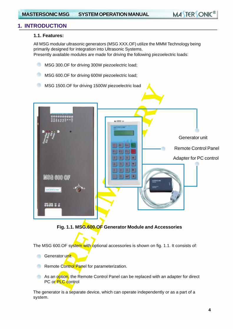
Fig. 1.1. MSG.600.OF Generator Module and Accessories
Generator unit
Adapter for PC control
Remote Control Panel
The MSG 600.OF system with optional accessories is shown on fig. 1.1. It consists of:
Generator unit
Remote Control Panel for parameterization.
As an option, the Remote Control Panel can be replaced with an adapter for directPC or PLC control
The generator is a separate device, which can operate independently or as a part of asystem.

MASTERSONIC MSG SYSTEM OPERATION MANUAL
5
PR
EL
IMIN
AR
Y
1. INTRODUCTION
1.3. System safety:
Read this manual thoroughly and follow all directions and instructions toassure maximum safety during operation.
Installation of the MasterSonic (generator/power supply) and associated transducers,the “MasterSonic System”, is to be performed by qualified technical personnel only.
The MasterSonic System is an electro-mechanical device that under certain circum-stances could present an electrical shock hazard to the operator.
The MasterSonic System should only be used and operated by properly trained andqualified technicians.
Qualified technicians licensed by the manufacturer should only perform servicing ofthe MasterSonic System.
Use of controls or adjustments or performance of procedures other than those speci-fied herein may result in hazardous exposure to ultrasonic energy.
To avoid electric shock, do not remove the case covers from the MasterSonic System.There are no user-serviceable parts inside any of these devices.
Connecting the Generator unit to mains that supplies improper voltage may cause theGenerator to malfunction or create a shock or fire hazard.
Proper system grounding cannot be insured unless unit is connected to properly wiredthree prong 220 - 230 VAC single-phase outlet with a sufficient current rating.
Do not remove the grounding prong on the line cord plug.
The Generator Electrical Supply cord should not be plugged into a device (e.g. “powerstrips”, “gang plugs”, etc.) other than an industrial grade wall socket. Such other usecould cause significant changes in voltage that could result in an electrical fault indica-tion. This condition may occur even though other equipment plugged into multi-outletsockets continues to operate.
Do not restrict airflow to the MasterSonic System by covering or enclosing in a sealedhousing while in operation. Airflow must circulate through the unit during operation tofacilitate proper cooling of electronic components.
1.2. Technical Characteristics of MSG 600.OF:
Power Supply Voltage 220/230 V; 50/60 HzMax. Input Power 700 WOutput Frequency from 19.020kHz until 46.728 kHzAverage Continuous Output Power 600 WPick Output (max. pulsed power) 3000 WOutput HF Voltage ~ 500 V-rmsDimensions (h x w x d) 250 x 150 x 150mm (see page 30)Weight 3.6 kg

MASTERSONIC MSG SYSTEM OPERATION MANUAL
6
PR
EL
IMIN
AR
Y
Do not place Generator on towel, foam or other soft surface since the material mayblock air vents. Blocking vents may cause Generator to overheat and malfunction orcreate a shock hazard.
Do not expose or immerse the MasterSonic System or the transducer in water orliquids. The system is not sealed against liquids and exposure may result in damage tothe equipment, create a shock hazard, or fire hazard.
Due to the general operating principles of the MasterSonic System and ultrasonics,this equipment is not suitable for use in environments where danger of explosion ex-ists.
The Generator should not be turned on until the Transducer Cable has been connectedto both the Generator and Transducer. Otherwise, damage to the Generator may re-sult.
When ultrasound output power is on, do not touch the transducer, booster, sonotrode,waveguide, or any device directly connected to these components; doing so may re-sult in injury.
Ear protection during operation of the system is highly recommended. Do not positionthe transducer, booster, sonotrode, waveguide, or any device directly connected tothese components near the technician or operators ears. The operating frequency ofthe MasterSonic System is below, within, and above the range of human hearing, andemits acoustic energy. Do not activate the system if system components are within 4feet (122 cm) of the ears of technician or operators.

MASTERSONIC MSG SYSTEM OPERATION MANUAL
7
PR
EL
IMIN
AR
Y
2. SYSTEM SET-UP
2.1. Installation and connection.
MasterSonic open frame generator modules are designed for internal mounting in thecontrol cabinets of Ultrasonic Systems. Such cabinets should be very well ventilated,protecting the generator module from excessive dust, moisture, and harmful chemicalagents.
Before you mount your MSG.XXX.OF generators make sure that all protection conditionsare strictly observed and satisfied.
The installation and electrical connections of the generator should be performed by aspecialist in electronics who is already experienced in Power Ultrasonics.
Fig. 2.1. depicts the main power supply schematic and the Acoustic Load Connections forthe MSG.XXX.OF.
2.1.2. Acoustic Load Connection.
The acoustic load can be connected with two-wire or three-wire cable. For improvedsafety the manufacturer strongly recommends connecting the acoustic load using thethree wire connection method.
As show in figure 2.1 above the 2-Pin terminal connector in the lower right side of theMSG.XXX.OF terminals 15-HV (High Voltage and 16-LV (Low Voltage) are used to supplyultrasonic power to the Acoustic Load (piezoelectric transducer).
2.1.1. Mains Power Supply Connection
Using proper three-wire power supply cable, connect the MSG.XXX.OF to the mains powerline as follows:
L1 – Line is connected to terminal 11;Neutral is connected to terminal 12;Ground is connected to terminal 13.
Note: MSG.XXX.OF is designed as a component part for integration into Ultrasonic sys-tems. Therefore it is not equipped with a Power Supply ON/OFF switch. Make sure theUltrasonic System you are assembling is provided with such switch.
Fig. 2.1. Installation and connection.
LineNeutral
Earth
220/230VAC, 50/60Hz
High voltage
11 12 13 14 15 16Acoustic load
Low voltage

MASTERSONIC MSG SYSTEM OPERATION MANUAL
8
PR
EL
IMIN
AR
Y
Terminal 15-HV is the high voltage ultrasonic signal output from the power transformerof the generator and should be connected to the Isolated Terminal of the transducer.
Terminal 16-LV should be connected to the inductive compensation of the transducerand to the acoustic system grounding (transducer housing or acoustic load mass).
Isolated Terminal (terminals between ceramic disks or rings without contact to front or back massof the converter) – This wire (normally Red / White / Black depending on supply source) is the HV (HighVoltage) terminal of the ultrasonic transducer.
Ground Terminal (terminals in contact with the front or back mass of the converter) – This wire(normally Green or Blue depending on supply source) is the LV (Low Voltage) terminal of the ultrasonictransducer.
Earth/Ground/Mass (normally Yellow / Green / Blue) – This wire is connected to the metal part ofthe Acoustic Load.
Connect the acoustic load to the MSG.XXX.OF as follows:
Connect the Isolated Terminal (normally Red Black or White) wire to terminal 15 - HV.
Connect the Ground Terminal (normally Green, Blue or Yellow) wire to terminal 16 - LV.
Connect the Earth/Ground/Mass (normally Yellow/Green/Blue) wire to terminal 14 - EARTH.
Fig. 2.1.2. Preferred 3-wire Acoustic Load connection.
High voltage
Earth/Ground
Grounded PiezoceramicTerminal
Isolated PiezoceramicTerminal
Low voltage
Acoustic load
CAUTION: The MasterSonic System should only be operated with manufacture approvedtransducers and cable.
ATTENTION! Do not connect the High Voltage (pin. 15) to grounding. This will damage theSystem.
2 Wire Connections:If the acoustic load can only be connected with a two-wire cable, identify the wire that isconnected to the acoustic load’s ground (Low Voltage - LV) and the one connected to theisolated terminal (High Voltage - HV). Connect the wire that is connected to the acousticload’s ground/mass/housing to terminal 16-LV and the isolated terminal wire to terminal 15-HV. Connect terminal 16-LV and terminal 14-EARTH together. This will ground the acousticload internally.
Note: The manufacturer does not recommend this connection method and should only beused if a three wire connection is not possible. Two wire connections should only be madeby a qualified electrical technician.
3 Wire Connections: (PREFERRED METHOD)The preferred method for connecting MasterSonic generator power supplies to acousticloads is with a three-wire cable, as shown on the following schematic.

MASTERSONIC MSG SYSTEM OPERATION MANUAL
9
PR
EL
IMIN
AR
Y2.1.3. Waveguide and Accessories Mounting:
Figure 2.1.3. System Assembly
CAUTION: Be careful when handling the acoustic load transducers or cable. The acousticload may be charged with electro-static high voltage that may produce an electrical shockto the installer if not handled properly. Before installation or before connecting the acousticload to the Mastersonic generator carefully touch the High Voltage Black wire to the LowVoltage Blue wire to short circuit and discharge electro-static build-up.
CAUTION: Do not place Generator on towel, foam or other soft surface that may blockgenerator air vents. Blocking any vents may cause the Generator to overheat, malfunction,or create a shock hazard.
CAUTION: Connecting the Generator unit to mains which supplies improper voltage maycause the Generator to malfunction or create a shock or fire hazard.
CAUTION: The Generator should not be turned on until the Transducer Cable has beenconnected to both the Generator and Transducer. Otherwise, damage to the Generator mayresult.
CAUTION: The Generator Electrical Supply cord should not be plugged into a device (e.g.“power strips”, “gang plugs”, etc.) other than an industrial grade wall socket. Such other usecould cause significant changes in voltage that could result in an electrical fault indication.This condition may occur even though other equipment plugged into multi-outlet socketscontinues to operate.
CAUTION: Ensure all connections and mating surfaces are clean and dry before assem-bly.
Use the supplied studs to interconnect the mechanical components. All componentsshould be threaded by hand until snug, DO NOT force the threads, they must turn insmoothly all the way until the mating faces touch. Use two open end pin (spanner)wrenches and make final tightening.
As depicted in Figure 2.1.4. the Wave Guide or Booster should be connected to the trans-ducer tip. Acoustic loads (probes, sonotrodes, etc.) are connected to the opposite end ofthe waveguide or Booster.
TRANSDUCER WAVE GUIDEACOUSTIC
LOAD
MASTERSONIC MSG SYSTEM OPERATION MANUAL
10
PR
EL
IMIN
AR
Y
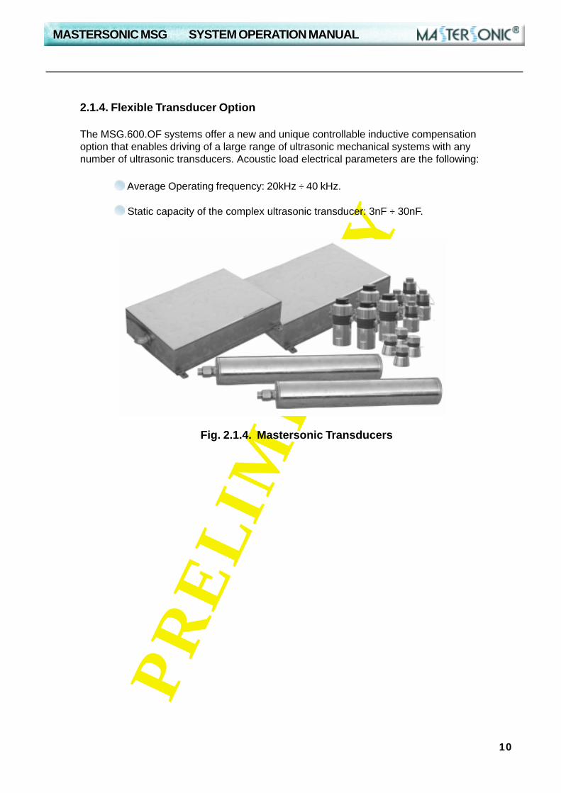
2.1.4. Flexible Transducer Option
The MSG.600.OF systems offer a new and unique controllable inductive compensationoption that enables driving of a large range of ultrasonic mechanical systems with anynumber of ultrasonic transducers. Acoustic load electrical parameters are the following:
Average Operating frequency: 20kHz ÷ 40 kHz.
Static capacity of the complex ultrasonic transducer: 3nF ÷ 30nF.
Fig. 2.1.4. Mastersonic Transducers
MASTERSONIC MSG SYSTEM OPERATION MANUAL
11
PR
EL
IMIN
AR
Y
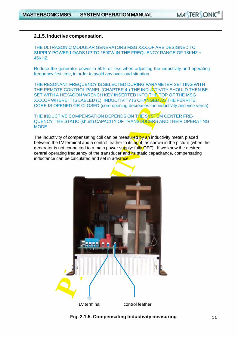
Fig. 2.1.5. Compensating Inductivity measuring
LV terminal control feather
2.1.5. Inductive compensation.
THE ULTRASONIC MODULAR GENERATORS MSG XXX.OF ARE DESIGNED TOSUPPLY POWER LOADS UP TO 1500W IN THE FREQUENCY RANGE OF 18KHZ ÷45KHZ.
Reduce the generator power to 50% or less when adjusting the inductivity and operatingfrequency first time, in order to avoid any over-load situation.
THE RESONANT FREQUENCY IS SELECTED DURING PARAMETER SETTING WITHTHE REMOTE CONTROL PANEL (CHAPTER 4.) THE INDUCTIVITY SHOULD THEN BESET WITH A HEXAGON WRENCH KEY INSERTED INTO THE TOP OF THE MSGXXX.OF WHERE IT IS LABLED (L). INDUCTIVITY IS CHANGED AS THE FERRITECORE IS OPENED OR CLOSED (core opening decreases the inductivity and vice versa).
THE INDUCTIVE COMPENSATION DEPENDS ON THE SYSTEM CENTER FRE-QUENCY, THE STATIC (shunt) CAPACITY OF TRANSDUCERS AND THEIR OPERATINGMODE.
The inductivity of compensating coil can be measured by an inductivity meter, placedbetween the LV terminal and a control feather to its right, as shown in the picture (when thegenerator is not connected to a main power supply: fully OFF). If we know the desiredcentral operating frequency of the transducer and its static capacitance, compensatinginductance can be calculated and set in advance.
MASTERSONIC MSG SYSTEM OPERATION MANUAL
12
PR
EL
IMIN
AR
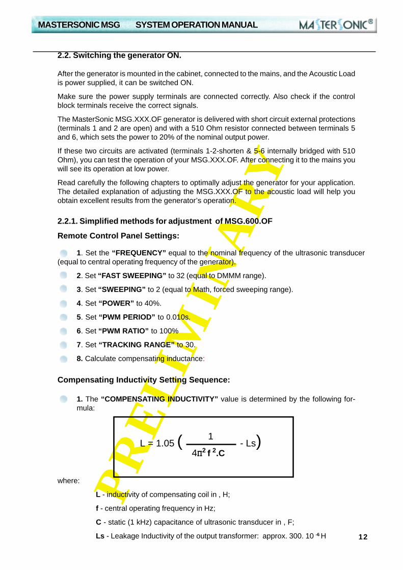
Y2.2.1. Simplified methods for adjustment of MSG.600.OF
Remote Control Panel Settings:
where:
L - inductivity of compensating coil in , H;
f - central operating frequency in Hz;
C - static (1 kHz) capacitance of ultrasonic transducer in , F;
Ls - Leakage Inductivity of the output transformer: approx. 300. 10 -6 H
1. Set the “FREQUENCY” equal to the nominal frequency of the ultrasonic transducer(equal to central operating frequency of the generator).
2. Set “FAST SWEEPING” to 32 (equal to DMMM range).
3. Set “SWEEPING” to 2 (equal to Math, forced sweeping range).
4. Set “POWER” to 40%.
5. Set “PWM PERIOD” to 0.010s.
6. Set “PWM RATIO” to 100%
7. Set “TRACKING RANGE” to 30.
8. Calculate compensating inductance:
L = 1.05 ( - Ls)1
4�2 f 2.C
Compensating Inductivity Setting Sequence:
1. The “COMPENSATING INDUCTIVITY” value is determined by the following for-mula:
2.2. Switching the generator ON.
After the generator is mounted in the cabinet, connected to the mains, and the Acoustic Loadis power supplied, it can be switched ON.
Make sure the power supply terminals are connected correctly. Also check if the controlblock terminals receive the correct signals.
The MasterSonic MSG.XXX.OF generator is delivered with short circuit external protections(terminals 1 and 2 are open) and with a 510 Ohm resistor connected between terminals 5and 6, which sets the power to 20% of the nominal output power.
If these two circuits are activated (terminals 1-2-shorten & 5-6 internally bridged with 510Ohm), you can test the operation of your MSG.XXX.OF. After connecting it to the mains youwill see its operation at low power.
Read carefully the following chapters to optimally adjust the generator for your application.The detailed explanation of adjusting the MSG.XXX.OF to the acoustic load will help youobtain excellent results from the generator’s operation.

MASTERSONIC MSG SYSTEM OPERATION MANUAL
13
PR
EL
IMIN
AR
Y2.3.Control Terminal Block.
The MSG.XXX.OF control is performed through the Control Terminal Block, describedbelow.
The control Terminal Block (fig. 2.3.) is placed on the upper side of the generator andimplements the following functions:
Terminals 1, 2, 3, 4, - Protection & Control; ON/OFF Power Control;Terminals 5 and 6 - Analogue setting of the power;Terminals 7, 8, 9, 10 - Remote Control Panel/PLC connection.
Fig. 2.3. Control Terminal Block
7 8 9 10
1 2 3 45 6
ATTENTION!
PLEASE, READ CAREFULLY THE WHOLE MANUAL BEFORE ADJUSTING THEMSG.XXX.OF GENERATOR.
OBSERVE THE FOLLOWING REQUIREMENTS DURING PARAMETER SETTING:
9.After the generator is started the output voltage and current should be checked. Theload HF current should vary in the range between 1.1 and 1.5 A-rms.
10. The compensating inductivity should be readjusted using the Hex Key until the“TRACKING” starts fluctuating around zero.
11. When tracking is near zero the system should be ready for operation.
“PWM-ratio” < 100%The following limits (below) shouldbe respected.
“PWM-ratio” = 100%No limits regarding all other pa-rameters.
“Tracking” = 0÷30
“Sweeping” = (0,7)
“Fast Sweeping” = 0÷255
“Tracking” = 0÷5
“Sweeping”< = (0,4)
“Fast Sweeping” = 0÷40
Table of Critical Settings

MASTERSONIC MSG SYSTEM OPERATION MANUAL
14
PR
EL
IMIN
AR
Y
2.3.1. External On/Off Power Control:
The external control of the generator is done through terminals on pins 1, 2, 3, 4 (fig. 2.3.1.).The way of connecting is shown on the drawing. Through pins 3, 4 the generator is switchedON or OFF. When the terminals are closed the generator is switched on and when theterminals are open, the generator is switched off.
NOTE: If the generator has been switched off because of activation of some internal block-ing or external protection the terminals remain closed. Next starting of the machine should bedone by opening and closing the terminals again.
NOTE: Terminals on pins 1 and 2 are protection inputs and they should be connected throughshort circuit enabling the generator to operate. If this circuit is open, the generator will stopoperating.
Fig. 2.3.1. External On/Off Power Control
2.3.2. Analog Input Power Control:
The power of the generator can be controlled in the following three ways: The power can be set during the parameter setting of the generator. The power can be set through the RS 485 serial interface by the changing power
command of the Remote Control Panel or PLC. The power can be set through the analog input - terminals 5 and 6. When a 2.5 k-
Ohm potentiometer is connected to terminals 5and 6, as shown on picture 2.4., the power isset from 0 to 100%.
2.3.3. Remote Control Connection:
The remote Control Panel or the MSA2218 Adapter for PC/PLC control is connected toterminals 7, 8, 9, 10 (see chapter 4.2.).
CAUTION: This connector is reserved exclusively for connecting MSA2218 Adapter ofMasterSonic Remote Control Panel. Connecting other devices to these terminals or usingthe power supply for other purposes may damage your generator.
Fig. 2.3.3. Remote Control Connection
Fig. 2.3.2. Analog Input Power Control

MASTERSONIC MSG SYSTEM OPERATION MANUAL
15
PR
EL
IMIN
AR
Y
2.4. Control Block
The Control Block of the generator is built on a separate PCB, which also holds the controlterminals.The generator’s control is designed on several microprocessors and a Field program-mable logic. This ensures the generation of sonic and ultrasonic frequencies, according tothe assignment and the selection of feedbacks.Through appropriate selection of different generation/control modules from the micropro-cessor control and determination of the feedbacks and their influence over the system youcan achieve extraordinary results with your MSG.600.OF generator.Control Board Jumpers (J1 and J2 on fig. 2.5.) allow you to choose between two blocks formodulation of the acoustic load’s resonant frequency. By switching one or both types ofmodulation (called “Sweeping”= Math Sweeping and “Fast Sweeping”= DMMM) you canobtain different results in the acoustic load.Turning the two jumper blocks OFF turns your MSG.XXX.OF generator into a conventionalgenerator, operating on resonant frequency of the acoustic load.
Jumper 2DMMM SweepingPolarity
Jumper 1Math Sweeping
ON/OFF
Jumper 1 OFF;Math Sweeping ON
Jumper 1 ON;Math Sweeping OFF
Jumper 2; Position 1;Positive DMMM Sweeping
Jumper 2; Position 2;Negative DMMM Sweeping
Fig 2.5. Controll Board Jumpers
2.5. Controll Board Jumpers
Fig. 2.5. shows the position of Jumpers J1 and J2 on the control PCB. It also shows the wayof choosing the oscillating modes.
MASTERSONIC MSG SYSTEM OPERATION MANUAL
16
PR
EL
IMIN
AR
Y
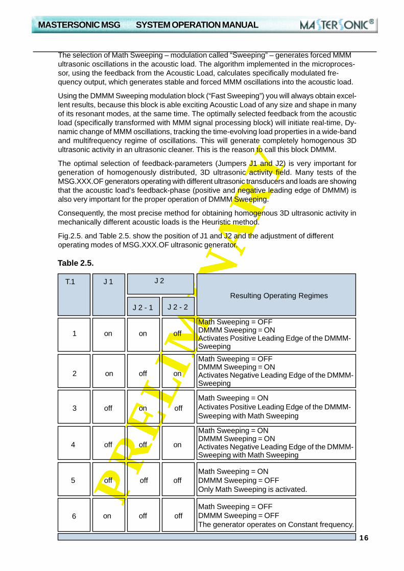
The selection of Math Sweeping – modulation called “Sweeping” – generates forced MMMultrasonic oscillations in the acoustic load. The algorithm implemented in the microproces-sor, using the feedback from the Acoustic Load, calculates specifically modulated fre-quency output, which generates stable and forced MMM oscillations into the acoustic load.
Using the DMMM Sweeping modulation block (“Fast Sweeping”) you will always obtain excel-lent results, because this block is able exciting Acoustic Load of any size and shape in manyof its resonant modes, at the same time. The optimally selected feedback from the acousticload (specifically transformed with MMM signal processing block) will initiate real-time, Dy-namic change of MMM oscillations, tracking the time-evolving load properties in a wide-bandand multifrequency regime of oscillations. This will generate completely homogenous 3Dultrasonic activity in an ultrasonic cleaner. This is the reason to call this block DMMM.
The optimal selection of feedback-parameters (Jumpers J1 and J2) is very important forgeneration of homogenously distributed, 3D ultrasonic activity field. Many tests of theMSG.XXX.OF generators operating with different ultrasonic transducers and loads are showingthat the acoustic load’s feedback-phase (positive and negative leading edge of DMMM) isalso very important for the proper operation of DMMM Sweeping.
Consequently, the most precise method for obtaining homogenous 3D ultrasonic activity inmechanically different acoustic loads is the Heuristic method.
Fig.2.5. and Table 2.5. show the position of J1 and J2 and the adjustment of differentoperating modes of MSG.XXX.OF ultrasonic generator.
Table 2.5.
T.1 J 1 J 2
J 2 - 1 J 2 - 2
1
2
3
4
5
6
on
on
on
on
on
on
on
off
off
offoff
offoff
off off off
off off
Math Sweeping = OFFDMMM Sweeping = ONActivates Positive Leading Edge of the DMMM-Sweeping
Math Sweeping = OFFDMMM Sweeping = ONActivates Negative Leading Edge of the DMMM-Sweeping
Math Sweeping = ONActivates Positive Leading Edge of the DMMM-Sweeping with Math Sweeping
Math Sweeping = ONDMMM Sweeping = ONActivates Negative Leading Edge of the DMMM-Sweeping with Math Sweeping
Math Sweeping = ONDMMM Sweeping = OFFOnly Math Sweeping is activated.
Math Sweeping = OFFDMMM Sweeping = OFFThe generator operates on Constant frequency.
Resulting Operating Regimes

MASTERSONIC MSG SYSTEM OPERATION MANUAL
17
PR
EL
IMIN
AR
Y
Table 2.6.
T.1 J 1 J 2
J 2 - 1 J 2 - 2
Resulting Operating Regimes
1 on on off
Math-Sweeping = OFF DMMM-Sweeping = ONActivates Positive Leading Edge of the DMMM-Sweeping; Significant Handy keyboard settings are:“Sweeping” = 0“Fast Sweeping” = 30÷180 (the best is 100)“Tracking Range” = 5÷20 (the best is 15)
2 on onoff
Math-Sweeping = OFF DMMM-Sweeping = ONActivates Negative Leading Edge of the DMMM-Sweeping;Significant Handy keyboard settings are:“Sweeping” = 0“Fast Sweeping” = 30÷180 (the best is 100)“Tracking Range” = 5÷20 (the best is 15)
3 on offoff
Math-Sweeping = ONActivates Positive Leading Edge of the DMMM-Sweeping with Math Sweeping; Settings:“Sweeping” = 2÷6 (the best is 2)“Fast Sweeping” = 30÷180 (the best is 100)“Tracking Range” = 5÷20 (the best is 15)
4 onoffoff
Math-Sweeping = ON DMMM-Sweeping = ONActivates Negative Leading Edge of the DMMM-Sweeping with Math Sweeping; Settings:“Sweeping” = 2÷6 (the best is 2)“Fast Sweeping” = 30÷180 (the best is 100)“Tracking Range” = 5÷20 (the best is 15)
5 off off off
Math-Sweeping = ON DMMM-Sweeping = OFFOnly Math Sweeping is activated;Significant Handy keyboard settings are:“Sweeping” = 2÷6 (the best is 2)“Fast Sweeping” = 0“Tracking Range” = 5÷20 (the best is 10)
6 on off off
Math-Sweeping = OFF DMMM-Sweeping = OFFConstant frequency operation = ONSignificant Handy keyboard settings are:“Sweeping” = 0“Fast Sweeping” = 0“Tracking Range” = 0
2.6. Sweeping Adjustment.
The MSGXXX.OF are designed for complex purposes and complex loads.
It is not recommended that MSGXX.OF are used in constant resonant frequency operating,plastic-welding applications. For that purpose the manufacturer offers MSGxxx.OW ultra-sonic generator type, which is especially designed for operating plastic welding transducers.
The MSGXXX.OF is designed to operate in DMMM Frequency regimes, as well as in Con-stant Frequency regimes. The table below describes all operating modes:

MASTERSONIC MSG SYSTEM OPERATION MANUAL
18
PR
EL
IMIN
AR
Y
Activating Only Dynamic MMM- Sweeping (without Math Sweeping): T.1 (1 + 2)Jumper J1 = ON (closed contacts) = Math Sweeping is deactivated,Jumper J2 = position 1 = Activates Positive Leading Edge of the DMMM-SweepingJumper J2 = position 2 = Activates Negative Leading Edge of the DMMM-Sweeping
Handy keyboard in this situation can produce the following meaningful settings and changes:Sweeping = 0; Fast Sweeping = 30 to 150 (best between 60 and 80); Power = 0 to 100%; PWMPeriod = 0.010s to 0.2s (best between 0.01s to 0.1s); PWM Ratio = 50% to 90% (best from 85% to90%); Frequency = 19.020 to 46.728 kHz; Tracking Range = 5 to 20 (best 7 to 15)
Activating Mixed Dynamic MMM- Sweeping and Math-Sweeping: T.1 (3 + 4)Jumper J1 = OFF (open contacts) = Math Sweeping is activated,Jumper J2 = position 1 = Activates Positive Leading Edge of the Dynamic MMM-SweepingJumper J2 = position 2 = Activates Negative Leading Edge of the MMM-Sweeping 2
Handy keyboard in this situation can produce the following meaningful settings and changes:Sweeping = 1 to 5 (best between 2 and 4); Fast Sweeping = 30 to 150 (best between 60 and80); Power = 0 to 100% (best between 85% and 90%); PWM Period = 0.010s to 0.1s; PWMRatio = 50% to 100% (best at 100%); Frequency = 19.020 to 46.728 kHz; Tracking Range =5 to 30 (best at 15)
Activating Only Math-Sweeping (without Dynamic MMM-Sweeping): T.1 (5)Jumper J1 = OFF (open contacts) = Math Sweeping is activated,Jumper J2 = OFF, (OPEN)Jumper J2 = OFF, (OPEN)
Handy keyboard in this situation can produce the following meaningful settings and changes:Sweeping = 1 to 5 (best between 2 and 4); Fast Sweeping = 0; Power = 0 to 100%; PWMPeriod = 0.010s to 0.2s (best between 0.01s and 0.1s); PWM Ratio = 50% to 100% (best from85% to 100%); Frequency = 19.020 to 46.728 kHz; Tracking Range = 5÷20 (best 7 to 15)
Activating Fixed Frequency Operating Regime: T.1 (6)Jumper J1 = ON (closed contacts) = Dynamic MMM-Sweeping is deactivated,Jumper J2 = position 1 = OPEN,Jumper J2 = position 2 = OPEN
Handy keyboard in this situation can produce the following meaningful settings and changes:Sweeping = 0Fast Sweeping = 0Power: from 0 to 100%PWM Period = 0.010sPWM Ratio = 100%Frequency: from 19.020 to 46.728 kHzTracking Range = 0

MASTERSONIC MSG SYSTEM OPERATION MANUAL
19
PR
EL
IMIN
AR
Y
2. SYSTEM SET-UP
2.7. MSG.600.OF Generator Parameters:
For mastering correct adjustments of your MSG.XXX.OF generator and obtaining excellentresults from its operation you should be very familiar with all its resources.
The correct adjustment is done through MasterSonic Remote Control Panel MSH-1 orMSA2218 Adapter for PC/PLC with the particularly developed MasterSonic software.
The following generator parameters can be set and adjusted:
The operation with the Remote Control Panel or the MasterSonic software through theMSA2218 Adapter is described in the following chapters.
Table 2.7.
Fast Sweeping(=DMMM)
19.020kHz ÷ 46.728kHz
0 ÷ 100 %
0.010s ÷ 1.000s
0 ÷ 100 %
0 ÷ 255 steps
0 ÷ 7 steps
0 ÷ 30 steps
DescriptionParameter
Frequency
Power
PWM Period
PWM Ratio
Sweeping (= MathSweeping)
Tracking Range
Central Operating Frequency of theultrasonic generator
The amplification coefficient in the FastSweeping range of the Central Operating
Frequency
The amplification coefficient proportional tothe Sweeping range of the Central Operating
Frequency
The power of the generator as a percentof the nominal power.
PWM Period duration at operation in ON/OFF mode of the generator.
The ON period as a percent of the PWMPeriod.
Max. acceptable correction of the CentralOperating Frequency as an absolute value,
computed by the in-built DPLL system.
Parameter Range
MASTERSONIC MSG SYSTEM OPERATION MANUAL
20
PR
EL
IMIN
AR
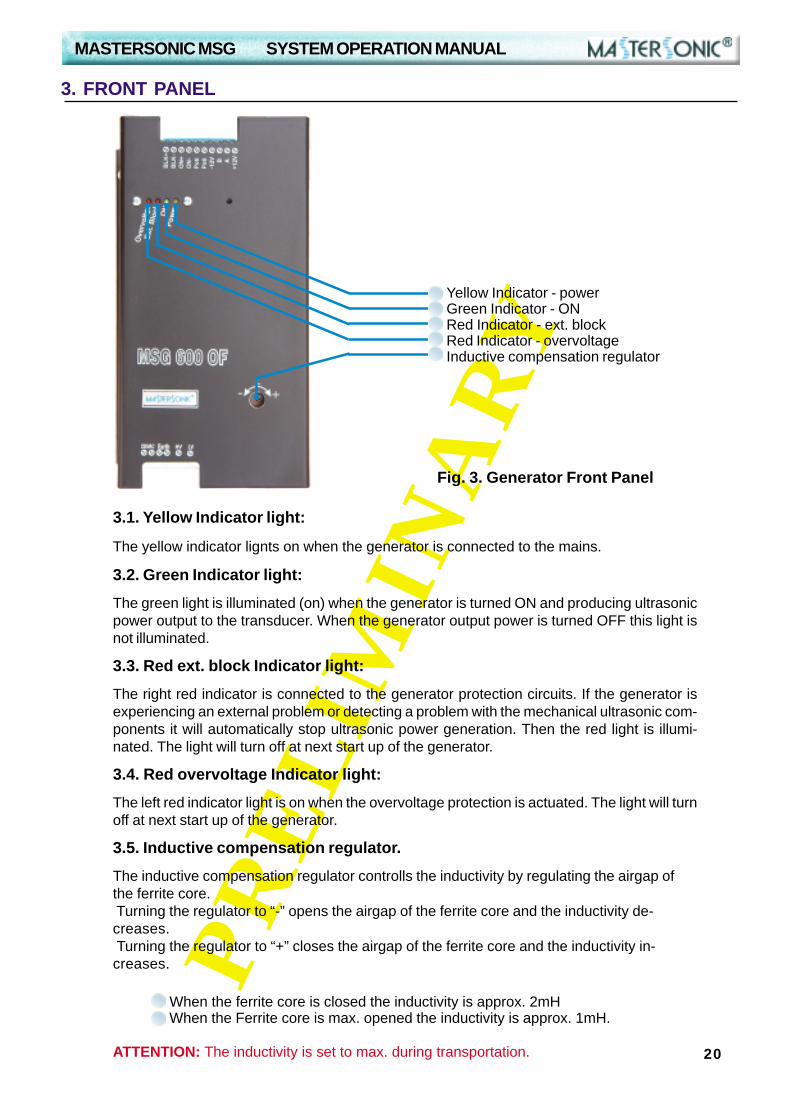
Y3.1. Yellow Indicator light:
The yellow indicator lignts on when the generator is connected to the mains.
3.2. Green Indicator light:
The green light is illuminated (on) when the generator is turned ON and producing ultrasonicpower output to the transducer. When the generator output power is turned OFF this light isnot illuminated.
3.3. Red ext. block Indicator light:
The right red indicator is connected to the generator protection circuits. If the generator isexperiencing an external problem or detecting a problem with the mechanical ultrasonic com-ponents it will automatically stop ultrasonic power generation. Then the red light is illumi-nated. The light will turn off at next start up of the generator.
3.4. Red overvoltage Indicator light:
The left red indicator light is on when the overvoltage protection is actuated. The light will turnoff at next start up of the generator.
3.5. Inductive compensation regulator.
The inductive compensation regulator controlls the inductivity by regulating the airgap ofthe ferrite core. Turning the regulator to “-” opens the airgap of the ferrite core and the inductivity de-creases. Turning the regulator to “+” closes the airgap of the ferrite core and the inductivity in-creases.
When the ferrite core is closed the inductivity is approx. 2mH When the Ferrite core is max. opened the inductivity is approx. 1mH.
ATTENTION: The inductivity is set to max. during transportation.
3. FRONT PANEL
Fig. 3. Generator Front Panel
Yellow Indicator - powerGreen Indicator - ONRed Indicator - ext. blockRed Indicator - overvoltageInductive compensation regulator

MASTERSONIC MSG SYSTEM OPERATION MANUAL
21
PR
EL
IMIN
AR
Y
4. REMOTE CONTROL PANEL
4.1. Remote Control Panel Description:The remote control panel is designed for rapid parameter setting and tuning of the ultrasonicgenerator while connected to the oscillating mechanical system.
4.2. Remote Control Panel Connection:Connection of the remote control panel to the generator is made by a special cable, which isconnected to terminals 7, 8, 9 and 10. The remote control connection should be made asshown on picture 2.3:
White
Black
Brown
-12V
A
+12V
8
9
10
Terminal No Cable Colour Signal Name
5
2
6
4
Handy pin #
7
B
Blue
4.3. Remote Control Panel Operation:The remote control panel has an LCD display with 2 rows of 16 symbols and keyboard with24 buttons that have the following functions:
Numeric keyboard from 0 to 9 and decimal point for entering new parameters.
Enter button to input parameters or initiate a Function.
“esc” button to escape or cancel current operation.
Up and Down Arrow buttons for increasing and de-creasing display values.
Left and Right Arrow buttons for readingthe LCD menu.
Power On Button - switches the Power Supply of theRemote Control Panel.
Alt Button for extending the functions of the RemoteContrrol Panel (intended for future applications).
Run Button Starts the generator.
Off Button Stops the generator.
Functions buttons:
F1 - reads parameter data stored in the controllermemory. Press F1 then select a memory position (0 to20) to view stored parameters.F2 - stores new parameter data from the buffer to aselected memory position (0 to 20) in the controller.F3 - downloads parameter data from the buffer to the MasterSonic generator memory.
Fig. 4. Remote ControlPanel
MASTERSONIC MSG SYSTEM OPERATION MANUAL
22
PR
EL
IMIN
AR
Y4.3.3. To set Ultrasonic Output Power – select desired parameter with LEFT and RIGHTARROW buttons. Select parameter value with UP and DOWN ARROW buttons, or withnumeric keyboard. The ENTER button downloads the current parameter value in the genera-tor.
4.3.4. To set PWM Period– select desired parameter with LEFT and RIGHT ARROW but-tons. Select parameter value with UP and DOWN ARROW buttons, or with numeric key-board. The ENTER button downloads the current parameter value in the generator.
4.3.5. To set PWM Ratio– select desired parameter with LEFT and RIGHT ARROW buttons.Select parameter value with UP and DOWN ARROW buttons, or with numeric keyboard.The ENTER button downloads the current parameter value in the generator.
4.3.6. To set Fast Sweeping select desired parameter with LEFT and RIGHT ARROW but-tons. Select parameter value with UP and DOWN ARROW buttons, or with numeric key-board. The ENTER button downloads the current parameter value in the generator.
4.3.7. To set Sweeping select desired parameter with LEFT and RIGHT ARROW buttons.Select parameter value with UP and DOWN ARROW buttons, or with numeric keyboard.The ENTER button downloads the current parameter value in the generator.
4.3.8. To set Tracking range select desired parameter with LEFT and RIGHT ARROW but-tons. Select parameter value with UP and DOWN ARROW buttons, or with numeric key-board. The ENTER button downloads the current parameter value in the generator.
4. REMOTE CONTROL PANEL
NOTE: If the Mastersonic generator is in operation (ultrasonic power is ON) when download-ing data from the remote control panel the generator will automatically turn OFF the ultra-sonic power for system safety. The generator may be restarted manually by switching theON/OFF switch, connected to terminals 1 and 2, or by pressing the RUN button of the Re-mote Control Panel.
4.3.1. When the remote control panel is connected to the MasterSonic generator, the activeset of generator parameters that are in its memory are automatically transferred to the bufferof the control panel.
4.3.2. To set Operating Frequency – select desired parameter with LEFT and RIGHT AR-ROW buttons. Select parameter value with UP and DOWN ARROW buttons, or with nu-meric keyboard. The ENTER button downloads the current parameter value in the generator.

MASTERSONIC MSG SYSTEM OPERATION MANUAL
23
PR
EL
IMIN
AR
Y
4. REMOTE CONTROL PANEL
ReadingData <<<<<<<
Uploading parameters fromthe generator memory tothe remote control panel
buffer.
SendingData >>>>>>>
Downloading parametersfrom the remote control
panel buffer to the generatormemory.
ReadMemory
Location xx
Reading parameters from aremote control panel
memory location (1 to 20) tothe remote control panel
buffer.
WriteMemory
Location xx
Writing parameters from theremote control panel bufferto the remote control panelmemory location (1 to 20).
Frequencyxx.xxx kHz(example:
21.940 kHz)
The average frequency ofthe ultrasonic transducers
(resonant mode).
PWM Periodx.xxxs (example:
1.190 s)
Period of Pulse WidthModulation (PWM in sec-
onds).
PWM Ratioxx% (example:
65%)
Ratio of Pulse WidthModulation (PWM
percent)
FastSweeping
Sweeping
xx stp (example:25 stp)
Fast Sweeping(0-255 steps)
x (example: 3) Sweeping (0-7)
TrackingRange
xx (example:25)
Tracking Range of DLLtracking (auto tune range
from 0-30)
InformationScreen
x.xx A(example:1.02A);+x (example: +3)
Only information screen.
Power xxx %(example:50%)
The current power as apercent of nominal power of
ultrasonic generator.
Function LCD DisplayPictures
LCD Displays Description of Action
Table 4.
MASTERSONIC MSG SYSTEM OPERATION MANUAL
24
PR
EL
IMIN
AR
Y
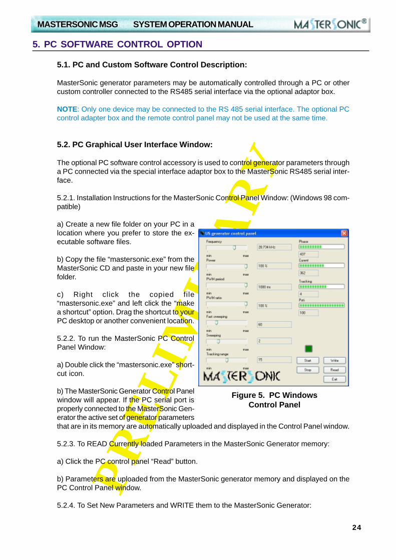
Figure 5. PC WindowsControl Panel
5.1. PC and Custom Software Control Description:
MasterSonic generator parameters may be automatically controlled through a PC or othercustom controller connected to the RS485 serial interface via the optional adaptor box.
NOTE: Only one device may be connected to the RS 485 serial interface. The optional PCcontrol adapter box and the remote control panel may not be used at the same time.
5.2. PC Graphical User Interface Window:
The optional PC software control accessory is used to control generator parameters througha PC connected via the special interface adaptor box to the MasterSonic RS485 serial inter-face.
5.2.1. Installation Instructions for the MasterSonic Control Panel Window: (Windows 98 com-patible)
a) Create a new file folder on your PC in alocation where you prefer to store the ex-ecutable software files.
b) Copy the file “mastersonic.exe” from theMasterSonic CD and paste in your new filefolder.
c) Right click the copied file“mastersonic.exe” and left click the “makea shortcut” option. Drag the shortcut to yourPC desktop or another convenient location.
5.2.2. To run the MasterSonic PC ControlPanel Window:
a) Double click the “mastersonic.exe” short-cut icon.
b) The MasterSonic Generator Control Panelwindow will appear. If the PC serial port isproperly connected to the MasterSonic Gen-erator the active set of generator parametersthat are in its memory are automatically uploaded and displayed in the Control Panel window.
5.2.3. To READ Currently loaded Parameters in the MasterSonic Generator memory:
a) Click the PC control panel “Read” button.
b) Parameters are uploaded from the MasterSonic generator memory and displayed on thePC Control Panel window.
5.2.4. To Set New Parameters and WRITE them to the MasterSonic Generator:
5. PC SOFTWARE CONTROL OPTION

MASTERSONIC MSG SYSTEM OPERATION MANUAL
25
PR
EL
IMIN
AR
Y
a) Each parameter may be set by either the sliding graphic bar or by typing specific numeri-cal values. (Parameter setting limitations are as described for the control panel above.)
b) When all parameters are set to the desired value Click the PC control panel “Write” button.
c) All parameters will be downloaded from the PC Control software to the MasterSonic gen-erator.
NOTE: If the Mastersonic generator is in operation (ultrasonic power is ON) when download-ing data from the PC control panel the generator will automatically turn OFF the ultrasonicpower for system safety. After downloading is completed the generator may be restartedmanually by pressing the front panel Green ON button or via the control panel start button.
5.2.5. Start or Stop the MasterSonic Generator:
a) After desired parameters have been set Click the “START” button.
b) Press the “STOP” button to stop ultrasonic power generation.
5.2.6. To Quit or Exit from the PC Control Window:• Click the “EXIT” button.
5. PC SOFTWARE CONTROL OPTION
5.3. Custom Controller or Special PC Command Options:
Using MasterSonic MSA2218 Adapter RS485 / RS232C interface, users may develop or useindustry standard controllers and PCs for programming and controlling the MasterSonic gen-erator via the optional interface adaptor box.
NOTE: Only one device may be connected to the MSGRS485 serial interface - terminals 7, 8, 9 and 10. ACustom Controller and the remote control panel maynot be used at the same time.
NOTE: This option is not a part of the standard sup-port. Assistance for hardware interface and program-ming are quoted by the manufacturer or distributor ona case by case basis.
5.3.1. The RS232C transfer protocol is semi-duplexand data transfer (reading/writing) and is controlled byRTS signaling.

MASTERSONIC MSG SYSTEM OPERATION MANUAL
26
PR
EL
IMIN
AR
Y
5.3.2. MasterSonic Generator Commands.
NOTE: Each command is terminated with carriage return (CR) ASCII code HEX =”0D “ ordecimal = 13
Inquiry Commands:
Inquiry Reply Formats:
#02fxxx(CR) Current Frequency reply. (xxx is frequency in kHz) o (0-255kHZ)
Current Fast Sweeping reply. o (0-255stp)
#02dxxx(CR) Current Sweeping reply. o (0-7)
#02pxxx(CR) Current Power reply. o (0-100%)
#02SR002 Firmware Version Reply
#02?xxxyyyzzzxxx - Phase (0-999 relative units)
yyy - Current (0-500) (0-5A)zzz - Tracking (0-60 relative units)
#02cxxx(CR) Current Electricity value reply. o (0-400) (0-4A)
#02wxxx(CR) Current PWM Period reply. o (1-100) - (10ms-1000ms)
#02mxxx(CR) Current PWM coefficient reply. o (0 - 100%)
#02txxx(CR) Current position of power potentiometer. o (0-100%)
inquire for Current Frequency of the generator
inquire for Current Fast Sweeping of the generator
inquire for Current PWM Period of the generator
inquire for Current PWM coefficient of the generator
inquire for Current potentiometer value
inquire for Current Electricity value of the generator
inquire for Firmware Version
inquire for Phase, Current and Tracking information
%04f(CR)
%04s(CR)
%04d(CR)
%04w(CR)
%04m(CR)
%04t(CR)
%04p(CR)
%04c(CR)
%04SR(CR)
%04?(CR)
#02sxxx(CR)
inquire for Current Sweeping of the generator
inquire for Current Power of the generator

MASTERSONIC MSG SYSTEM OPERATION MANUAL
27
PR
EL
IMIN
AR
Y
5. PC SOFTWARE CONTROL OPTION
Comments:
MODE: AsynchronousDATA: 8 data bitsStop: 1Baud rate: 19200Parity: NoTxd - 1 = SendRxd - 0 = Receive
Data transfer: According to RS232 / RS485 Protocol.
Note: The manufacturer recommends that only original MasterSonic MSA2218 Adapteris used with the MasterSonic generator.
Start/Stop Generator Ultrasonic Power Commands:
@04start(CR) Start command
@04stop(CR) Stop command
@04wr(CR) Write command
Set New Parameter Value Commands:
#04fxxx(CR) Sets a new Operating Frequency for the generator (0-255)
#04sxxx(CR) Sets a new Fast Sweeping Frequency (0-255)
#04dxxx(CR) Sets a new Sweeping Frequency (0-7)
#04wxxx(CR) Sets a new PWM Period 1-100 (10-1000ms)
#04mxxx(CR) Sets a new PWM Coefficient (0-100%)
NOTE: The generator replies with a character “>(CR)” after receiving the setting param-eters. The reply is not controlled.
#04pxxx(CR) Sets new Power (0-100%)

MASTERSONIC MSG SYSTEM OPERATION MANUAL
28
PR
EL
IMIN
AR
Y
The product warranty is detailed in the general conditions of sale or as part of a special saleagreement.
The warranty does not apply and may be voided for equipment subject to unauthorized modi-fications, repair, misuse, abuse, negligence or accident.
Equipment that, in our judgment, shows evidence of having been used in violation of operat-ing instructions will be ineligible for service under this warranty.
The MasterSonic equipment is designed for maximum operator safety and incorporates built-in safety devices. Any modifications to these safety features will void the warranty. The Manu-facturer assumes no responsibilities for consequential damages incurred due to modifica-tions to the said equipment.
Under no circumstances shall the Manufacturer be liable to the purchaser or to any otherperson for any incidental or consequential damages or loss of profit or product resulting fromany malfunction or failure of this MasterSonic product.
No liability is assumed for expenses or damages resulting from interruptions in operation ofthe product or damages to material in process.
The Manufacturer reserves the rights not to warrant horns, sonotrodes, and waveguides ofunusual or experimental design that in our judgment are more likely to fail in use.
Within the period guaranteed, we will repair or replace free of charge, at our sole discretion,all parts that are defective because of material or workmanship, not including costs for re-moving or installing parts.
Liability, whether based on warranty, negligence or other cause, arising out of and/or inciden-tal to sale, use or operation of the transducer elements, or any part thereof, shall not in anycase exceed the cost of repair or replacement of the defective equipment, and such repair orreplacement shall be the exclusive remedy of the purchaser, and in no case will we be re-sponsible for any and/or all consequential or incidental damages including without limitation,and/or all consequential damages arising out of commercial losses.
6. LIMITATION OF WARRANTY

MASTERSONIC MSG SYSTEM OPERATION MANUAL
29
PR
EL
IMIN
AR
Y
WARNING: To avoid electric shock, do not remove the case cover from the Generator orTransducer. There are no user-serviceable parts inside any of these components.
IMPORTANT NOTICE: For the protection of employees, shippers, receivers, various per-sonnel, and to remain in compliance with Transit Laws, material returned to the Manufactureror its designated representatives must be rendered free of any hazardous, noxious or radio-active contamination.
Should the user of this device have any questions or comments as to its specifications, use,limitations, or maintenance, the Manufacturers Service Representative can be contacted asfollows:
7. SERVICE
By Post/Mail: MP InterconsultingAttn: MasterSonic ServiceMarais 362400 Le Locle, Switzerland
Telephone/Fax: +41 32 9314045E-mail: [email protected];www.mpi-ultrasonics.com

MASTERSONIC MSG SYSTEM OPERATION MANUAL
30
PR
EL
IMIN
AR
Y
OUTLINE DIMENSIONS OF MSG 300.OF
MASTERSONIC MSG SYSTEM OPERATION MANUAL
31
PR
EL
IMIN
AR
Y
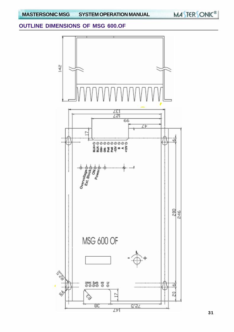
OUTLINE DIMENSIONS OF MSG 600.OF
MASTERSONIC MSG SYSTEM OPERATION MANUAL
32
PR
EL
IMIN
AR
Y
PARAMETERS SETTINGS OF MSG.600.OF - TUBULAR TRANSDUCER
First place the tubular transducer into a vessel with water. Tubular transducer should be fullyimmersed (do not operate it in air). Connect all cables. Connect the MSG generator to 220-230 VAC, main supply voltage. Then, use the handy keyboard (MSG generator programmingunit) and set all parameters for constant frequency operation (no sweeping, no modulation):
Sweeping: 0Fast sweeping 0Power: 50%PWM period: 0.010 sPWM ratio: 100%Frequency: 26.650 kHzTracking range 0
Start testing the system, starting with 26.650 kHz (central operating frequency, or frequencycarrier) by increasing it slowly. The best operating regime will be found close to 28.000 kHz(or on a little bit lower frequency). The second relatively well operating regime will be found inthe carrier frequency area between 30.000 kHz and 33.500 kHz. The best results will befound later at 28 kHz and 33 kHz carrier frequencies.
Now, start introducing frequency and time modulating parameters, using the handy program-ming unit (gradually increasing or decreasing above given values). Make new settings, as forinstance (very good operating regime):
Sweeping: 2Fast sweeping 50Power: 100%PWM period: 0.100 sPWM ratio: 100%Frequency: 28.280 kHzTracking range 10
Test parameters variations around above given values (applying the values given below),using very thin aluminum (kitchen) foil, to see when the fastest foil perforation (in water) isachieved (take the thinnest foil you can find).
Sweeping: Try from 30 until 150 (very good 60 until 80)Fast sweeping: Try from 1 until 5 (very good 2 until 4)Power: From 0 to 100%PWM period: Try from 0.020 s until 0.200 s (good from 0.05 until 0.1)PWM ratio: Try from 50% until 95% (very good 100%)Frequency: Try from 27.000 until 33.000 kHz (very good 28 and 33 kHz)Tracking range: Try from 5 until 20 (very good 7 until 15)
If MSG generator suddenly stops, this would mean that you made certain parameter setting/s that is out of the operating range (out of the safe operating margin). Just change theparameter in question, or reduce the power, and restart the MSG generator.
Memorize the best set/s of parameters (there are 10 available memories for memorizingdifferent sets of parameters).