system-level modeling and refinement of a canny edge detector
TRANSCRIPT
Center for Embedded Computer SystemsUniversity of California, Irvine
System-Level Modeling and Refinement of a Canny EdgeDetector
Xu Han ,Yasaman Samei and Rainer Domer
Technical Report CECS-12-13November 7, 2012
Center for Embedded Computer SystemsUniversity of California, IrvineIrvine, CA 92697-3425, USA
(949) 824-8059
{hanx, ysameisy, doemer}@uci.eduhttp://www.cecs.uci.edu/
System-Level Modeling and Refinement of a Canny EdgeDetector
Xu Han ,Yasaman Samei and Rainer Domer
Technical Report CECS-12-13November 7, 2012
Center for Embedded Computer SystemsUniversity of California, IrvineIrvine, CA 92697-3425, USA
(949) 824-8059
{hanx, ysameisy, doemer}@uci.eduhttp://www.cecs.uci.edu
Abstract
Electronic System Level design methodology and supportingtools simplifies the design ofcomplex embedded systems. In this paper, a case study with anapplication example of cannyedge detector is presented. We recoded a C reference code of canny to an initial specificationmodel in SpecC. In order to yield best design from automated system level design tools, werefined the specification model by exploiting data-level parallelism, pipelining and convertingfloating-point computation to fixed-point in the initial model. With the optimized specificationmodel, we used System-on-Chip Environment (SCE) to explorethe design space, find allocationand mapping scheme which can achieve real-time computing, and refinement the specificationmodel to Transaction level Model.

Contents
1 Introduction 1
2 Overview of Canny Edge Detector 2
3 System Level Modeling of Canny Edge Detector 33.1 Initial Specification Model . . . . . . . . . . . . . . . . . . . . . . . . . . . . . . 33.2 Model Refinements . . . . . . . . . . . . . . . . . . . . . . . . . . . . . . . . . . 3
3.2.1 Parallelization ofguassiansmooth. . . . . . . . . . . . . . . . . . . . . . 33.2.2 Pipelining . . . . . . . . . . . . . . . . . . . . . . . . . . . . . . . . . . . 53.2.3 Converting Floating-point to Fixed-point . . . . . . . . . . . . . . . . . . 6
4 Model Refinements and Implementation using SCE 6
5 Conclusion 8
References 9
A Appendix 10A.1 Source Code of Canny Edge Detector in SpecC . . . . . . . . . . . . . . . .. . . 10A.2 Makefile for TLM generation in SCE . . . . . . . . . . . . . . . . . . . . . . . . .30
i

List of Figures
1 Top-Down System-Level Design Flow . . . . . . . . . . . . . . . . . . . . . . . .22 Canny Edge Detector Flowchart . . . . . . . . . . . . . . . . . . . . . . . . . . .33 Initial Specification Model . . . . . . . . . . . . . . . . . . . . . . . . . . . . . . 44 Canny Profile using SCE . . . . . . . . . . . . . . . . . . . . . . . . . . . . . . . 45 Parallelguassiansmooth . . . . . . . . . . . . . . . . . . . . . . . . . . . . . . . 56 5-stage Pipelined Canny Edge Detector [5] . . . . . . . . . . . . . . . . . . . .. . 57 Canny Profile using SCE afterguassiansmoothparallelized . . . . . . . . . . . . 68 PE Allocation . . . . . . . . . . . . . . . . . . . . . . . . . . . . . . . . . . . . . 69 Behavior Mapping . . . . . . . . . . . . . . . . . . . . . . . . . . . . . . . . . . 710 Network Allocation . . . . . . . . . . . . . . . . . . . . . . . . . . . . . . . . . . 811 Network Connectivity . . . . . . . . . . . . . . . . . . . . . . . . . . . . . . . . . 8
ii

List of Tables
1 Timing of various Models . . . . . . . . . . . . . . . . . . . . . . . . . . . . . . . 8
iii

System-Level Modeling and Refinement of a Canny Edge Detector
Xu Han ,Yasaman Samei and Rainer Domer
Center for Embedded Computer SystemsUniversity of California, IrvineIrvine, CA 92697-3425, USA
{hanx, ysameisy, doemer}@uci.eduhttp://www.cecs.uci.edu
Abstract
Electronic System Level design methodology and supporting tools simplifiesthe design of complexembedded systems. In this paper, a case study with an application exampleof canny edge detectoris presented. We recoded a C reference code of canny to an initial specification model in SpecC.In order to yield best design from automated system level design tools, we refined the specificationmodel by exploiting data-level parallelism, pipelining and converting floating-point computation tofixed-point in the initial model. With the optimized specification model, we used System-on-ChipEnvironment (SCE) to explore the design space, find allocation and mapping scheme which canachieve real-time computing, and refinement the specification model to Transaction level Model.
1 Introduction
The growing market for embedded systems, typically portable electronic devices, demands productswith better functionality and shorter time to market. The complexity of designing, debugging andverifying systems containing increasing number of HW/SW components presents great challengeto embedded design methodology. Electronic system level (ESL) design engages the problem usingmodels of higher abstraction level. In ESL design, a system is firstly specified using a System LevelDesign Language (SLDL). The initial model is called a specification model. Then supporting toolscan efficiently perform design space exploration, high-level synthesis, and software refinement tocycle-accurate level on the specification model.
Figure 1 [3] presents an ESL design methodology and tool sets SCE [2] using SpecC SLDL.Firstly, the product specification is captured using SpecC. Then, architecture refinement is per-formed, which involves allocation of processing elements (PE), mapping behaviors, channels and
1

untimed
estimated timing
timing accurate
cycle accurate
constraintsT
I
M
I
N
Gpure functional
transaction level
bus functional
RTL / IS
requirementsS
T
R
U
C
T
U
R
E
Specification model
Algor.IP
Proto.IP
Architecture model
Communication refinement
Comp.IP
Implementation model
Software
synthesis
Interface
synthesis
Hardware
synthesisRTOS
IPRTLIP
Architecture refinement
Capture
Communication model
Product specification
Manufacturing
Figure 1: Top-Down System-Level Design Flow
variables to PEs. The result of architecture refinement is a system architecture model of concurrentPEs with abstract communication in channels. Next, scheduling refinement is performed to serial-ize the execution of behaviors on each PE according to either static or dynamic scheduling (RTOSsupport) chosen by designer. The result of this step is a system model withabstract RTOS insertedin each PE. Next, communication refinement implements the abstract communication channels be-tween PEs. By allocating system busses and map the channels to them in SCE, we can then generatea bus-functional model of the system. Finally, the SW and HW components of bus-functional modelis synthesized.
This report focuses on a case study of the ESL design methodology usingan application exampleof canny edge detecter (canny). Canny is modeled in SpecC, optimized fordesign and refined topin-accurate level using SCE.
2 Overview of Canny Edge Detector
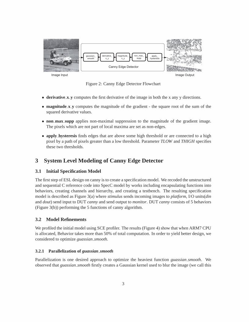
The canny edge detector is developed by Prof. John F. Canny in 1986 and our work is based on areference implementation [1]. The algorithm applies five functions in sequential to an input imageand detects all the edges in it (Figure 2).
The five functions are:
• gaussiansmooth creates a gaussian kernel based on input parameterSIGMA(the standarddeviation of the gaussian smoothing filter), and then used the kernel to filter or blur each pixelof the image to reduce the noise. The blurring occurs first horizontally andthen vertically.
2
gaussian_
smooth
derivative_
x_y
non_max_
suppmagnitude_
x_yapply_
hysteresis
Canny Edge Detector
Image Input Image Output
Figure 2: Canny Edge Detector Flowchart
• derivative x y computes the first derivative of the image in both the x any y directions.
• magnitude x y computes the magnitude of the gradient - the square root of the sum of thesquared derivative values.
• non max supp applies non-maximal suppression to the magnitude of the gradient image.The pixels which are not part of local maxima are set as non-edges.
• apply hysteresisfinds edges that are above some high threshold or are connected to a highpixel by a path of pixels greater than a low threshold. ParameterTLOWandTHIGH specifiesthese two thresholds.
3 System Level Modeling of Canny Edge Detector
3.1 Initial Specification Model
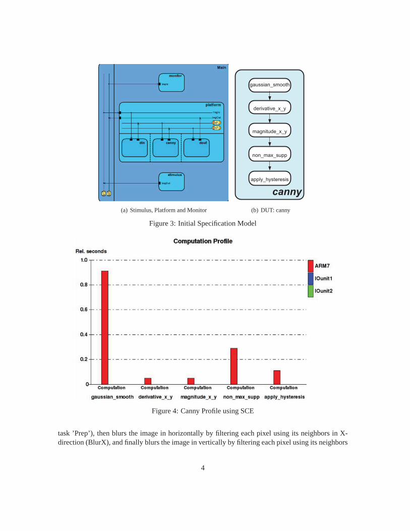
The first step of ESL design on canny is to create a specification model. We recoded the unstructuredand sequential C reference code into SpecC model by works including encapsulating functions intobehaviors, creating channels and hierarchy, and creating a testbench. The resulting specificationmodel is described as Figure 3(a) wherestimulussends incoming images toplatform, I/O units(dinanddout) send input to DUTcannyand send output tomonitor. DUT cannyconsists of 5 behaviors(Figure 3(b)) performing the 5 functions of canny algorithm.
3.2 Model Refinements
We profiled the initial model using SCE profiler. The results (Figure 4) showthat when ARM7 CPUis allocated, Behavior takes more than 50% of total computation. In order to yield better design, weconsidered to optimizeguassiansmooth.
3.2.1 Parallelization ofguassian smooth
Parallelization is one desired approach to optimize the heaviest functionguassiansmooth. Weobserved thatguassiansmoothfirstly creates a Gaussian kernel used to blur the image (we call this
3
(a) Stimulus, Platform and Monitor
derivative_x_y
gaussian_smooth
magnitude_x_y
non_max_supp
apply_hysteresis
canny
(b) DUT: canny
Figure 3: Initial Specification Model
Figure 4: Canny Profile using SCE
task ’Prep’), then blurs the image in horizontally by filtering each pixel usingits neighbors in X-direction (BlurX), and finally blurs the image in vertically by filtering each pixelusing its neighbors
4
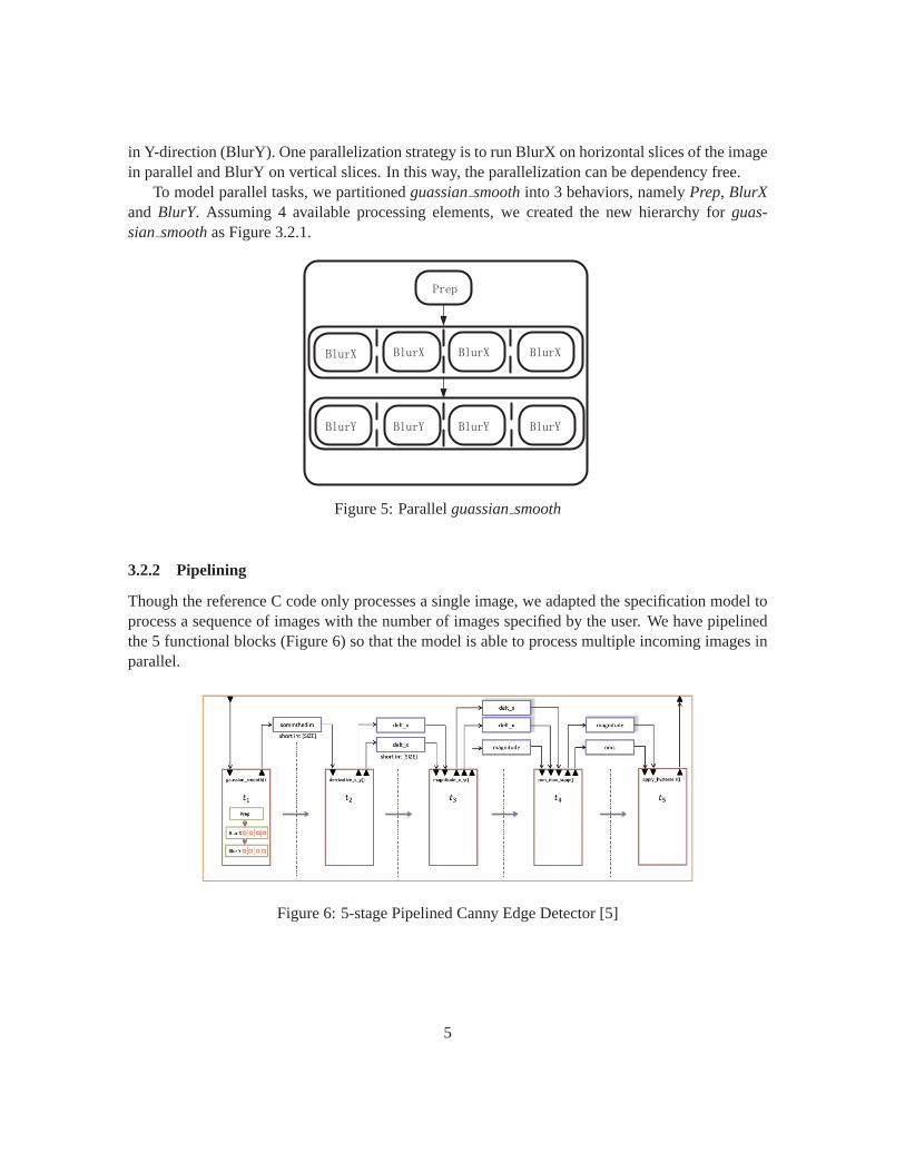
in Y-direction (BlurY). One parallelization strategy is to run BlurX on horizontal slices of the imagein parallel and BlurY on vertical slices. In this way, the parallelization can bedependency free.
To model parallel tasks, we partitionedguassiansmoothinto 3 behaviors, namelyPrep, BlurXand BlurY. Assuming 4 available processing elements, we created the new hierarchy for guas-sian smoothas Figure 3.2.1.
Figure 5: Parallelguassiansmooth
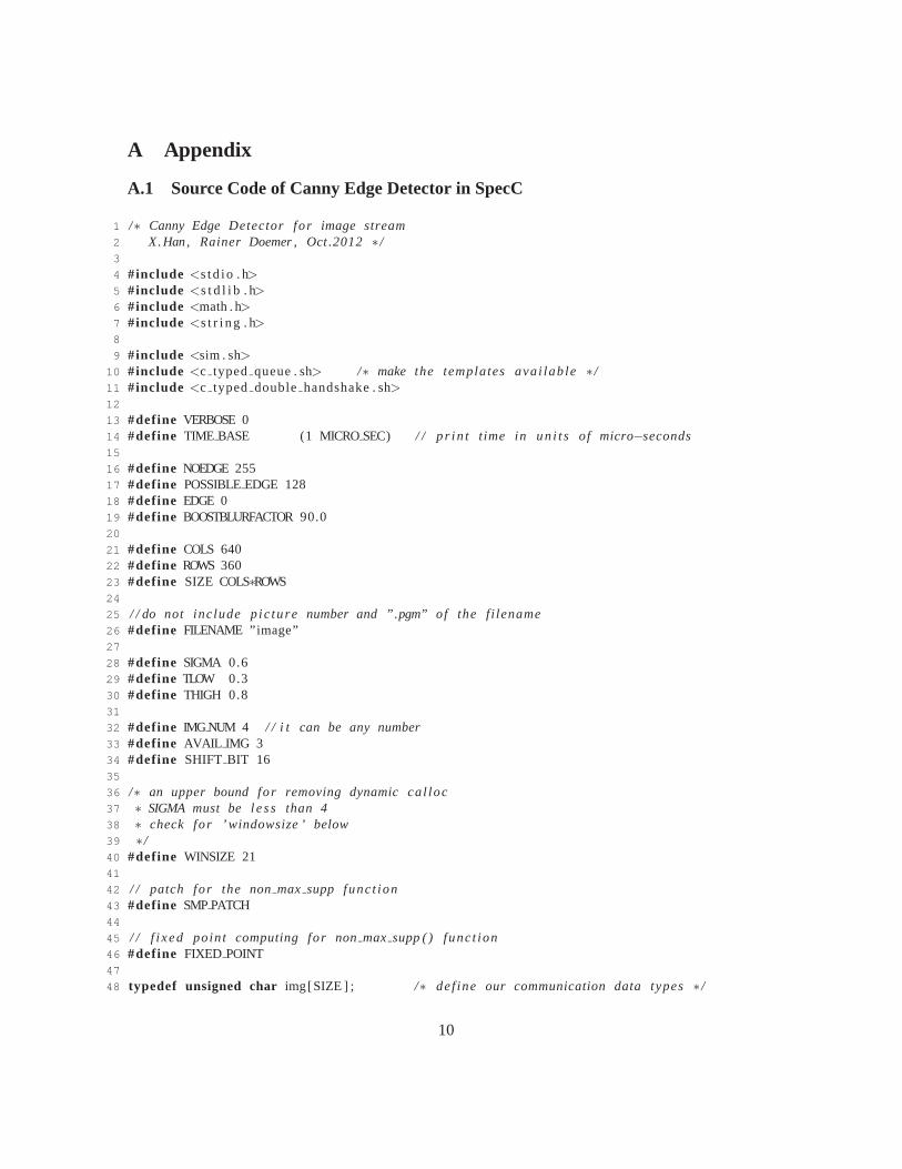
3.2.2 Pipelining
Though the reference C code only processes a single image, we adaptedthe specification model toprocess a sequence of images with the number of images specified by the user. We have pipelinedthe 5 functional blocks (Figure 6) so that the model is able to process multiple incoming images inparallel.
Figure 6: 5-stage Pipelined Canny Edge Detector [5]
5

3.2.3 Converting Floating-point to Fixed-point
Figure 7 shows updated profiling results whenguassiansmoothis parallelized using 4 processingunit and tentatively mapped onto two hardware unit using SCE. Nownon maxsuppcontains thelargest amount of computation in all behaviors and becomes the bottleneck in the pipeline.
Figure 7: Canny Profile using SCE afterguassiansmoothparallelized
From SCE profiling statistics, 95.6% of the operations innon maxsuppare floating-point. Inorder to balance the pipeline stages, we converted floating-point computation to fixed-point withoutloss of accuracy [4].
The source code of the refined specification model can be found in Appendix A.1.
4 Model Refinements and Implementation using SCE
Figure 8: PE Allocation
6

Figure 9: Behavior Mapping
In this section different steps of design space exploration shown in Figure 1, are performed overCanny example. The SCE tool is used to perform a step by step implementation. The refinementsteps start with architecture refinement. In this step processing elements(PE) are added to designand canny’s behaviors are allocated to them. The added PEs and their corresponding behaviors areshown in the Figure 8 and Figure 9.
The canny algorithms are running on a ARM7TDMI target processor andas it is shown inFigure 9 two sub behavior of theguassiansmoothfunction are allocated to separate hardware units.Since theguassiansmoothfunction is computationally expensive, extra hardware units are addedto improve the performance of the design.
In the next step of system level design process different behaviors of the design are scheduled.In the canny example no dynamic scheduling algorithm is applied and behaviors execution order isstatic and same as the original specification of the design. After scheduling the behaviors, decisionson communication between system components are made. Two system BUSes are selected in cannyexample; AMBA BUS belong to allocated ARM CPU and a Hardware bus. The allocated BUSes
7

Figure 10: Network Allocation
Figure 11: Network Connectivity
are illustrated in Figure 10. Following the BUS allocation, components connectivity, Masters andSlaves are defined. In Figure 11 component’s connections over the BUSare clarified.
Finally the implementation is brought down to Transaction level Model(TLM). Table 1 reflectsthe simulation results in each step. The detailed configuration of the TLM generation is describedin the Makefile in Appendix .
Table 1: Timing of various ModelsModel Simulation Time(micro second)
Specification Model 0Architecture Model 1982972Scheduled Architecture Model 1982972Network Model 1982972TLM Model 2012235
5 Conclusion
In this report, we have created a system-level model of a canny edge detector based on its C referencecode. We refined the model by exploiting parallelism, pipelining and convertingfloating-point tofixed-point for the bottleneck pipelining stage. We then use SCE to find an allocation and mappingscheme and refine the model automatically to Transaction level Model. The model is verified bysimulation.
8

References
[1] Canny Edge Detector. ftp://figment.csee.usf.edu/pub/Edge Comparison/sourcecode/canny.src.
[2] Rainer Domer, Andreas Gerstlauer, Junyu Peng, Dongwan Shin, Lukai Cai, Haobo Yu, SamarAbdi, and Daniel Gajski. System-on-Chip Environment: A SpecC-based Framework for Het-erogeneous MPSoC Design.EURASIP Journal on Embedded Systems, 2008(647953):13 pages,2008.
[3] Andreas Gerstlauer, Rainer Domer, Junyu Peng, and Daniel D. Gajski.System Design: APractical Guide with SpecC. Kluwer, 2001.
[4] Jiang Wan. Modeling of a canny edge detector system-on-chip for a digital camera. EECS222A2012 Spring Course Project Report.
[5] Ching-Yao Wang. Modeling of a canny edge detector system-on-chipfor a digital camera.EECS222A 2012 Spring Course Project Report.
9
A Appendix
A.1 Source Code of Canny Edge Detector in SpecC
1 /∗ Canny Edge Detector for image stream2 X.Han, Rainer Doemer , Oct .2012∗ /3
4 #include <s td io . h>5 #include <s t d l i b . h>6 #include <math . h>7 #include <s t r i ng . h>8
9 #include <sim . sh>10 #include <c typed queue . sh> /∗ make the templates avai lab le∗ /11 #include <c typed double handshake . sh>12
13 #define VERBOSE 014 #define TIME BASE (1 MICROSEC) / / p r in t t ime in un i t s of micro−seconds15
16 #define NOEDGE 25517 #define POSSIBLEEDGE 12818 #define EDGE 019 #define BOOSTBLURFACTOR 90.020
21 #define COLS 64022 #define ROWS 36023 #define SIZE COLS∗ROWS24
25 / / do not inc lude p ic ture number and ”.pgm” of the f i lename26 #define FILENAME ”image”27
28 #define SIGMA 0.629 #define TLOW 0.330 #define THIGH 0.831
32 #define IMG NUM 4 / / i t can be any number33 #define AVAIL IMG 334 #define SHIFT BIT 1635
36 /∗ an upper bound for removing dynamic ca l loc37 ∗ SIGMA must be less than 438 ∗ check for ’ windowsize ’ below39 ∗ /40 #define WINSIZE 2141
42 / / patch for the nonmax supp funct ion43 #define SMPPATCH44
45 / / f i xed point computing for nonmax supp ( ) funct ion46 #define FIXED POINT47
48 typedef unsigned char img[SIZE ] ; /∗ def ine our communication data types∗ /
10
49 typedef short imgs [SIZE ] ;50
51 DEFINE I TYPED SENDER( img , img) / / c reates in te r face iimg sender52 DEFINE I TYPED RECEIVER( img , img) / / c reates in te r face iimg rece iver53 DEFINE I TYPED TRANCEIVER( img , img) / / c reates in te r face iimg t rance iver54
55 DEFINE C TYPED QUEUE( img , img) / / c reates channel cimg queue56
57
58 behavior Monitor ( i img rece iver ImgIn , in sim time StartTime [IMGNUM] )59 {60 unsigned char edge [SIZE ] ;61
62 /∗∗∗∗∗∗∗∗∗∗∗∗∗∗∗∗∗∗∗∗∗∗∗∗∗∗∗∗∗∗∗∗∗∗∗∗∗∗∗∗∗∗∗∗∗∗∗∗∗∗∗∗∗∗∗∗∗∗∗∗∗∗∗∗∗∗∗∗∗∗∗∗∗∗∗∗∗∗63 ∗ Function : write pgm image64 ∗ Purpose : This funct ion wr i tes an image in PGM format . The f i le i s e i the r65 ∗ wr i t ten to the f i l e spec i f i ed by outf i lename or to standard output i f66 ∗ outf i lename = NULL. A comment can be wr i t ten to the header i f coment != NULL.67 ∗∗∗∗∗∗∗∗∗∗∗∗∗∗∗∗∗∗∗∗∗∗∗∗∗∗∗∗∗∗∗∗∗∗∗∗∗∗∗∗∗∗∗∗∗∗∗∗∗∗∗∗∗∗∗∗∗∗∗∗∗∗∗∗∗∗∗∗∗∗∗∗∗∗∗∗∗∗ /68 in t write pgm image (char ∗outf i lename , unsigned char ∗image , in t rows ,69 in t cols , const char ∗comment , in t maxval )70 {71 FILE ∗ fp ;72
73 /∗∗∗∗∗∗∗∗∗∗∗∗∗∗∗∗∗∗∗∗∗∗∗∗∗∗∗∗∗∗∗∗∗∗∗∗∗∗∗∗∗∗∗∗∗∗∗∗∗∗∗∗∗∗∗∗∗∗∗∗∗∗∗∗∗∗∗∗∗∗∗∗∗∗∗74 ∗ Open the output image f i l e for wr i t ing i f a f i lename was given. I f no75 ∗ f i lename was provided , se t fp to wr i te to standard output .76 ∗∗∗∗∗∗∗∗∗∗∗∗∗∗∗∗∗∗∗∗∗∗∗∗∗∗∗∗∗∗∗∗∗∗∗∗∗∗∗∗∗∗∗∗∗∗∗∗∗∗∗∗∗∗∗∗∗∗∗∗∗∗∗∗∗∗∗∗∗∗∗∗∗∗∗ /77 i f ( outf i lename == NULL) fp = stdout ;78 e lse{79 i f ( ( fp = fopen ( outf i lename , ”w” ) ) == NULL){80 f p r i n t f ( s tder r , ” Error wr i t ing the f i l e %s in write pgm image ( ) .\n” ,81 outf i lename ) ;82 return ( 0 ) ;83 }84 }85
86 /∗∗∗∗∗∗∗∗∗∗∗∗∗∗∗∗∗∗∗∗∗∗∗∗∗∗∗∗∗∗∗∗∗∗∗∗∗∗∗∗∗∗∗∗∗∗∗∗∗∗∗∗∗∗∗∗∗∗∗∗∗∗∗∗∗∗∗∗∗∗∗∗∗∗∗87 ∗ Write the header informat ion to the PGM f i l e .88 ∗∗∗∗∗∗∗∗∗∗∗∗∗∗∗∗∗∗∗∗∗∗∗∗∗∗∗∗∗∗∗∗∗∗∗∗∗∗∗∗∗∗∗∗∗∗∗∗∗∗∗∗∗∗∗∗∗∗∗∗∗∗∗∗∗∗∗∗∗∗∗∗∗∗∗ /89 f p r i n t f ( fp , ”P5\n%d %d\n” , cols , rows ) ;90 i f (comment != NULL)91 i f ( s t r l e n (comment)<= 70) f p r i n t f ( fp , ”# %s\n” , comment ) ;92 f p r i n t f ( fp , ”%d\n” , maxval ) ;93
94 /∗∗∗∗∗∗∗∗∗∗∗∗∗∗∗∗∗∗∗∗∗∗∗∗∗∗∗∗∗∗∗∗∗∗∗∗∗∗∗∗∗∗∗∗∗∗∗∗∗∗∗∗∗∗∗∗∗∗∗∗∗∗∗∗∗∗∗∗∗∗∗∗∗∗∗95 ∗ Write the image data to the f i l e .96 ∗∗∗∗∗∗∗∗∗∗∗∗∗∗∗∗∗∗∗∗∗∗∗∗∗∗∗∗∗∗∗∗∗∗∗∗∗∗∗∗∗∗∗∗∗∗∗∗∗∗∗∗∗∗∗∗∗∗∗∗∗∗∗∗∗∗∗∗∗∗∗∗∗∗∗ /97 i f ( ( unsigned) rows != fwr i te ( image , cols , rows , fp ) ){98 f p r i n t f ( s tder r , ” Error wr i t ing the image data in write pgm image ( ) .\n” ) ;99 i f ( fp != stdout ) fc lose ( fp ) ;
100 return ( 0 ) ;
11

101 }102
103 i f ( fp != stdout ) fc lose ( fp ) ;104 return ( 1 ) ;105 }106
107 void main ( )108 {109 char outf i lename [128] ; /∗ Name of the output ”edge” image∗ /110 sim time t , t2 ;111 s im t ime st r ing buf , buf2 ;112 in t i , n ;113
114 for ( i =0; i<IMG NUM; i ++)115 {116 ImgIn . rece ive(&edge ) ;117
118 t = now ( ) ;119 p r i n t f ( ”%8s : Monitor received image%d.\n” , t ime2st r ( buf , t /TIMEBASE) , i ) ;120 t2 = t − StartTime [ i ] ;121 p r i n t f ( ”%8s : Image processing took %8s micro seconds .\n” ,122 t ime2st r ( buf , t /TIMEBASE) , t ime2st r ( buf2 , t2 /TIMEBASE) ) ;123
124
125 /∗∗∗∗∗∗∗∗∗∗∗∗∗∗∗∗∗∗∗∗∗∗∗∗∗∗∗∗∗∗∗∗∗∗∗∗∗∗∗∗∗∗∗∗∗∗∗∗∗∗∗∗∗∗∗∗∗∗∗∗∗∗∗∗∗∗∗∗∗∗∗∗∗∗∗∗126 ∗ Write out the edge image to a f i l e .127 ∗∗∗∗∗∗∗∗∗∗∗∗∗∗∗∗∗∗∗∗∗∗∗∗∗∗∗∗∗∗∗∗∗∗∗∗∗∗∗∗∗∗∗∗∗∗∗∗∗∗∗∗∗∗∗∗∗∗∗∗∗∗∗∗∗∗∗∗∗∗∗∗∗∗∗∗ /128
129 n=i%AVAIL IMG;130
131 s p r i n t f ( outf i lename , ”%ss %3.2 f l %3.2 f h %3.2 f %d .pgm” , FILENAME, SIGMA, TLOW, THIGH, i ) ;132 i f (VERBOSE) p r i n t f ( ”Writ ing the edge iname in the f i l e %s .\n” , outf i lename ) ;133 i f ( write pgm image ( outf i lename , edge , ROWS, COLS, ”” , 255) == 0){134 f p r i n t f ( s tder r , ” Error wr i t ing the edge image , %s .\n” , outf i lename ) ;135 ex i t ( 1 ) ;136 }137 } / / fo r138
139
140 ex i t ( 0 ) ; / / done tes t ing , qu i t the s imulat ion141 }142 } ;143
144 behavior Stimulus ( i img sender ImgOut ,out sim time StartTime [IMGNUM] )145 {146 unsigned char image [SIZE ] ;147
148 /∗∗∗∗∗∗∗∗∗∗∗∗∗∗∗∗∗∗∗∗∗∗∗∗∗∗∗∗∗∗∗∗∗∗∗∗∗∗∗∗∗∗∗∗∗∗∗∗∗∗∗∗∗∗∗∗∗∗∗∗∗∗∗∗∗∗∗∗∗∗∗∗∗∗∗∗∗∗149 ∗ Function : readpgm image150 ∗ Purpose : This funct ion reads in an image in PGM format . The image can be151 ∗ read in from e i the r a f i l e or from standard input . The image i sonly read152 ∗ from standard input when inf i lename = NULL. Because the PGM format inc ludes
12
153 ∗ the number of columns and the number of rows in the image , these are read154 ∗ from the f i l e . Memory to s tore the image i s a l located OUTSIDEt h i s funct ion .155 ∗ The found image s i ze i s checked against the expected rows andcols .156 ∗ Al l comments in the header are discarded in the process of reading the157 ∗ image . Upon fa i lu re , t h i s funct ion returns 0 , upon sucess i tre turns 1.158 ∗∗∗∗∗∗∗∗∗∗∗∗∗∗∗∗∗∗∗∗∗∗∗∗∗∗∗∗∗∗∗∗∗∗∗∗∗∗∗∗∗∗∗∗∗∗∗∗∗∗∗∗∗∗∗∗∗∗∗∗∗∗∗∗∗∗∗∗∗∗∗∗∗∗∗∗∗∗ /159 in t read pgm image (const char ∗ inf i lename , unsigned char ∗image0 , in t rows , in t cols )160 {161 FILE ∗ fp ;162 char buf [71 ] ;163 in t r , c ;164
165 /∗∗∗∗∗∗∗∗∗∗∗∗∗∗∗∗∗∗∗∗∗∗∗∗∗∗∗∗∗∗∗∗∗∗∗∗∗∗∗∗∗∗∗∗∗∗∗∗∗∗∗∗∗∗∗∗∗∗∗∗∗∗∗∗∗∗∗∗∗∗∗∗∗∗∗166 ∗ Open the input image f i l e for reading i f a f i lename was given .I f no167 ∗ f i lename was provided , se t fp to read from standard input .168 ∗∗∗∗∗∗∗∗∗∗∗∗∗∗∗∗∗∗∗∗∗∗∗∗∗∗∗∗∗∗∗∗∗∗∗∗∗∗∗∗∗∗∗∗∗∗∗∗∗∗∗∗∗∗∗∗∗∗∗∗∗∗∗∗∗∗∗∗∗∗∗∗∗∗∗ /169 i f ( inf i lename == NULL) fp = s td in ;170 e lse{171 i f ( ( fp = fopen ( inf i lename , ” r ” ) ) == NULL){172 f p r i n t f ( s tder r , ” Error reading the f i l e %s in read pgm image ( ) .\n” ,173 in f i lename ) ;174 return ( 0 ) ;175 }176 }177
178 /∗∗∗∗∗∗∗∗∗∗∗∗∗∗∗∗∗∗∗∗∗∗∗∗∗∗∗∗∗∗∗∗∗∗∗∗∗∗∗∗∗∗∗∗∗∗∗∗∗∗∗∗∗∗∗∗∗∗∗∗∗∗∗∗∗∗∗∗∗∗∗∗∗∗∗179 ∗ Ver i fy tha t the image i s in PGM format , read in the number of columns180 ∗ and rows in the image and scan past a l l of the header informat ion .181 ∗∗∗∗∗∗∗∗∗∗∗∗∗∗∗∗∗∗∗∗∗∗∗∗∗∗∗∗∗∗∗∗∗∗∗∗∗∗∗∗∗∗∗∗∗∗∗∗∗∗∗∗∗∗∗∗∗∗∗∗∗∗∗∗∗∗∗∗∗∗∗∗∗∗∗ /182 f ge ts ( buf , 70 , fp ) ;183 i f ( strncmp ( buf , ”P5” ,2) != 0){184 f p r i n t f ( s tder r , ”The f i l e %s i s not in PGM format in ” , inf i lename ) ;185 f p r i n t f ( s tder r , ” readpgm image ( ) .\ n” ) ;186 i f ( fp != s td in ) fc lose ( fp ) ;187 return ( 0 ) ;188 }189 do{ f ge ts ( buf , 70 , fp ) ; }while ( buf [0 ] == ’# ’ ) ; /∗ sk ip a l l comment l i nes∗ /190 sscanf ( buf , ”%d%d” , &c , &r ) ;191 i f ( c != cols | | r != rows){192 f p r i n t f ( s tder r , ”The f i l e %s i s not a %d by %d image in ” , inf i lename , cols , rows ) ;193 f p r i n t f ( s tder r , ” readpgm image ( ) .\ n” ) ;194 i f ( fp != s td in ) fc lose ( fp ) ;195 return ( 0 ) ;196 }197 do{ f ge ts ( buf , 70 , fp ) ; }while ( buf [0 ] == ’# ’ ) ; /∗ sk ip a l l comment l i nes∗ /198
199 i f ( ( unsigned) rows != fread ( image0 , cols , rows , fp ) ){200 f p r i n t f ( s tder r , ” Error reading the image data in read pgm image ( ) .\n” ) ;201 i f ( fp != s td in ) fc lose ( fp ) ;202 return ( 0 ) ;203 }204
13
205 i f ( fp != s td in ) fc lose ( fp ) ;206 return ( 1 ) ;207 }208
209 void main ( )210 {211 sim time t ;212 s im t ime st r ing buf ;213 in t i =0 ,n=0;214 char in f i lename [40 ] ;215
216
217
218
219 for ( i =0; i < IMG NUM; i ++)220 {221 n=i%AVAIL IMG;222
223 s p r i n t f ( inf i lename , ”%s%d .pgm” ,FILENAME, n ) ;224
225 i f (VERBOSE) p r i n t f ( ”Reading the image %s .\n” , inf i lename ) ;226 i f ( read pgm image ( inf i lename , image , ROWS, COLS) == 0){227 f p r i n t f ( s tder r , ” Error reading the input image , %s .\n” , inf i lename ) ;228 ex i t ( 1 ) ;229 }230 t = now( ) / TIME BASE;231 p r i n t f ( ”%8s : Stimulus sends image%d.\n” , t ime2st r ( buf , t ) , i ) ;232 StartTime [ i ] = t ;233
234 ImgOut . send ( image ) ;235
236 }237
238
239 }240 } ;241
242
243 behavior Prep ( i img rece iver ImgIn , inout in t center ,244 inout f l oa t kernel [WINSIZE] , inout img image )245 {246 in t windowsize ; /∗ Dimension of the gaussian kernel .∗ /247
248 void make gaussiankernel (f l oa t sigma )249 {250 in t i ;251 f l oa t x , fx , sum=0.0;252
253 windowsize = 1 + 2∗ c e i l (2 .5 ∗ sigma ) ;254 center = windowsize / 2;255
256 i f (VERBOSE) p r i n t f ( ” The kernel has %d elements .\n” , windowsize ) ;
14
257
258 for ( i =0; i<windowsize ; i ++){259 x = ( f l oa t ) ( i − center ) ;260 fx = pow(2.71828 , −0.5∗x∗x / ( sigma∗sigma ) ) / ( sigma∗ sq r t (6.2831853)) ;261 kernel [ i ] = fx ;262 sum += fx ;263 }264
265 for ( i =0; i<windowsize ; i ++) kernel [ i ] /= sum;266
267 i f (VERBOSE){268 p r i n t f ( ”The f i l t e r c o e f f i c i e n t s are :\n” ) ;269 for ( i =0; i<windowsize ; i ++)270 p r i n t f ( ” kernel[%d] = %f\n” , i , kernel [ i ] ) ;271 }272 }273
274 void main ( )275 {276 ImgIn . rece ive(&image ) ;277
278 /∗∗∗∗∗∗∗∗∗∗∗∗∗∗∗∗∗∗∗∗∗∗∗∗∗∗∗∗∗∗∗∗∗∗∗∗∗∗∗∗∗∗∗∗∗∗∗∗∗∗∗∗∗∗∗∗∗∗∗∗∗∗∗∗∗∗∗∗∗∗∗∗∗∗∗∗279 ∗ Create a 1−dimensional gaussian smoothing kernel .280 ∗∗∗∗∗∗∗∗∗∗∗∗∗∗∗∗∗∗∗∗∗∗∗∗∗∗∗∗∗∗∗∗∗∗∗∗∗∗∗∗∗∗∗∗∗∗∗∗∗∗∗∗∗∗∗∗∗∗∗∗∗∗∗∗∗∗∗∗∗∗∗∗∗∗∗∗ /281 i f (VERBOSE) p r i n t f ( ” Computing the gaussian smoothing kernel .\n” ) ;282 make gaussiankernel (SIGMA) ;283 }284 } ;285
286
287 behavior BlurX ( in img image , in in t center , in f l oa t kernel [WINSIZE] ,288 inout f l oa t tempim[SIZE ] , in in t rowStart , in in t rowEnd)289 {290
291 void main ( )292 {293 in t r , c , cc ; /∗ Counter var iab les . ∗ /294 f l oa t dot , /∗ Dot product summing var iab le .∗ /295 sum; /∗ Sum of the kernel weights var iab le .∗ /296
297 /∗∗∗∗∗∗∗∗∗∗∗∗∗∗∗∗∗∗∗∗∗∗∗∗∗∗∗∗∗∗∗∗∗∗∗∗∗∗∗∗∗∗∗∗∗∗∗∗∗∗∗∗∗∗∗∗∗∗∗∗∗∗∗∗∗∗∗∗∗∗∗∗∗∗∗∗298 ∗ Blur in the x − d i rec t ion .299 ∗∗∗∗∗∗∗∗∗∗∗∗∗∗∗∗∗∗∗∗∗∗∗∗∗∗∗∗∗∗∗∗∗∗∗∗∗∗∗∗∗∗∗∗∗∗∗∗∗∗∗∗∗∗∗∗∗∗∗∗∗∗∗∗∗∗∗∗∗∗∗∗∗∗∗∗ /300 i f (VERBOSE) p r i n t f ( ” Bluring the image in the X−d i rec t i on .\n” ) ;301 for ( r=rowStart ; r<rowEnd ; r ++){302 for ( c=0;c<COLS; c++){303 dot = 0 .0 ;304 sum = 0.0 ;305 for ( cc=(−center ) ; cc<=center ; cc++){306 i f ( ( ( c+cc ) >= 0) && ( ( c+cc ) < COLS)){307 dot += (f l oa t ) image [ r∗COLS+(c+cc ) ] ∗ kernel [ center+cc ] ;308 sum += kernel [ center+cc ] ;
15
309 }310 }311 tempim[ r∗COLS+c ] = dot /sum;312 }313 }314 }315 } ;316
317
318 behavior BlurY ( out imgs smoothedim , in in t center , in f l oa t kernel [WINSIZE] ,319 in f l oa t tempim[SIZE ] , in in t co lS tar t , in in t colEnd )320 {321
322 void main ( )323 {324 in t r , c , r r ; /∗ Counter var iab les . ∗ /325 f l oa t dot , /∗ Dot product summing var iab le .∗ /326 sum; /∗ Sum of the kernel weights var iab le .∗ /327
328 /∗∗∗∗∗∗∗∗∗∗∗∗∗∗∗∗∗∗∗∗∗∗∗∗∗∗∗∗∗∗∗∗∗∗∗∗∗∗∗∗∗∗∗∗∗∗∗∗∗∗∗∗∗∗∗∗∗∗∗∗∗∗∗∗∗∗∗∗∗∗∗∗∗∗∗∗329 ∗ Blur in the y − d i rec t ion .330 ∗∗∗∗∗∗∗∗∗∗∗∗∗∗∗∗∗∗∗∗∗∗∗∗∗∗∗∗∗∗∗∗∗∗∗∗∗∗∗∗∗∗∗∗∗∗∗∗∗∗∗∗∗∗∗∗∗∗∗∗∗∗∗∗∗∗∗∗∗∗∗∗∗∗∗∗ /331 i f (VERBOSE) p r i n t f ( ” Bluring the image in the Y−d i rec t i on .\n” ) ;332 for ( c=co lS ta r t ; c<colEnd ; c++){333 for ( r =0; r<ROWS; r ++){334 sum = 0.0 ;335 dot = 0 .0 ;336 for ( r r=(−center ) ; r r<=center ; r r ++){337 i f ( ( ( r+ r r ) >= 0) && ( ( r+ r r ) < ROWS)){338 dot += tempim [ ( r+ r r )∗COLS+c ] ∗ kernel [ center+ r r ] ;339 sum += kernel [ center+ r r ] ;340 }341 }342 smoothedim [ r∗COLS+c ] = (short in t ) ( dot∗BOOSTBLURFACTOR/sum + 0 . 5 ) ;343 }344 }345 }346 } ;347
348
349 behavior BlurX par (in img image , in in t center , in f l oa t kernel [WINSIZE] ,350 inout f l oa t tempim[SIZE ] )351 {352 BlurX blurX1 ( image , center , kernel , tempim , ( (ROWS/4)∗0) , ( (ROWS/4 )∗1 ) ) ;353 BlurX blurX2 ( image , center , kernel , tempim , ( (ROWS/4)∗1) , ( (ROWS/4 )∗2 ) ) ;354 BlurX blurX3 ( image , center , kernel , tempim , ( (ROWS/4)∗2) , ( (ROWS/4 )∗3 ) ) ;355 BlurX blurX4 ( image , center , kernel , tempim , ( (ROWS/4)∗3) , ( (ROWS/4 )∗4 ) ) ;356
357 void main ( )358 {359 par{360 blurX1 . main ( ) ;
16

361 blurX2 . main ( ) ;362 blurX3 . main ( ) ;363 blurX4 . main ( ) ;364 }365 }366 } ;367
368
369 behavior BlurY par (out imgs smoothedim , in in t center , in f l oa t kernel [WINSIZE] ,370 in f l oa t tempim[SIZE ] )371 {372 BlurY blurY1 ( smoothedim , center , kernel , tempim , ( (COLS/4)∗0) , ( (COLS/4 )∗1 ) ) ;373 BlurY blurY2 ( smoothedim , center , kernel , tempim , ( (COLS/4)∗1) , ( (COLS/4 )∗2 ) ) ;374 BlurY blurY3 ( smoothedim , center , kernel , tempim , ( (COLS/4)∗2) , ( (COLS/4 )∗3 ) ) ;375 BlurY blurY4 ( smoothedim , center , kernel , tempim , ( (COLS/4)∗3) , ( (COLS/4 )∗4 ) ) ;376
377 void main ( )378 {379 par{380 blurY1 . main ( ) ;381 blurY2 . main ( ) ;382 blurY3 . main ( ) ;383 blurY4 . main ( ) ;384 }385 }386 } ;387
388 behavior Blur done ( in imgs smoothedim ,out imgs smoothedimg )389 {390 void main ( )391 {392 smoothedimg = smoothedim ;393 }394 } ;395
396 behavior GaussianSmooth ( i img rece iver ImgIn , out imgs smoothedimg )397 {398 img image ;399 in t center ;400 f l oa t kernel [WINSIZE] ;401 f l oa t tempim[SIZE ] ;402 imgs smoothedim ;403
404 Prep prep ( ImgIn , center , kernel , image ) ;405 BlurX par blurX par ( image , center , kernel , tempim ) ;406 BlurY par blurY par ( smoothedim , center , kernel , tempim ) ;407 Blur done blur done ( smoothedim , smoothedimg ) ;408
409 void main ( )410 {411 prep . main ( ) ;412 blurX par . main ( ) ;
17
413 blurY par . main ( ) ;414 blur done . main ( ) ;415 }416 } ;417
418
419 behavior Derivative X Y ( in imgs smoothedim ,out imgs del ta x , out imgs de l ta y )420 {421 /∗∗∗∗∗∗∗∗∗∗∗∗∗∗∗∗∗∗∗∗∗∗∗∗∗∗∗∗∗∗∗∗∗∗∗∗∗∗∗∗∗∗∗∗∗∗∗∗∗∗∗∗∗∗∗∗∗∗∗∗∗∗∗∗∗∗∗∗∗∗∗∗∗∗∗∗∗∗∗422 ∗ PROCEDURE: de r r i va t i vex y423 ∗ PURPOSE: Compute the f i r s t de r i va t i ve of the image in both the x any y424 ∗ d i rec t ions . The d i f f e r e n t i a l f i l t e r s tha t are used are :425 ∗426 ∗ −1427 ∗ dx = −1 0 +1 and dy = 0428 ∗ +1429 ∗430 ∗ NAME: Mike Heath431 ∗ DATE: 2/15/96432 ∗∗∗∗∗∗∗∗∗∗∗∗∗∗∗∗∗∗∗∗∗∗∗∗∗∗∗∗∗∗∗∗∗∗∗∗∗∗∗∗∗∗∗∗∗∗∗∗∗∗∗∗∗∗∗∗∗∗∗∗∗∗∗∗∗∗∗∗∗∗∗∗∗∗∗∗∗∗∗ /433 void der iva t i ve x y ( short in t ∗smoothedimg , in t rows , in t cols ,434 short in t ∗deltax , short in t ∗del tay )435 {436 in t r , c , pos ;437
438 /∗∗∗∗∗∗∗∗∗∗∗∗∗∗∗∗∗∗∗∗∗∗∗∗∗∗∗∗∗∗∗∗∗∗∗∗∗∗∗∗∗∗∗∗∗∗∗∗∗∗∗∗∗∗∗∗∗∗∗∗∗∗∗∗∗∗∗∗∗∗∗∗∗∗∗∗439 ∗ Compute the x−der i va t i ve . Adjust the der i va t i ve at the borders to avoid440 ∗ los ing p ixe l s .441 ∗∗∗∗∗∗∗∗∗∗∗∗∗∗∗∗∗∗∗∗∗∗∗∗∗∗∗∗∗∗∗∗∗∗∗∗∗∗∗∗∗∗∗∗∗∗∗∗∗∗∗∗∗∗∗∗∗∗∗∗∗∗∗∗∗∗∗∗∗∗∗∗∗∗∗∗ /442 i f (VERBOSE) p r i n t f ( ” Computing the X−d i rec t i on der i va t i ve .\n” ) ;443 for ( r =0; r<rows ; r ++){444 pos = r ∗ cols ;445 del tax [ pos ] = smoothedimg [ pos+1]− smoothedimg [ pos ] ;446 pos++;447 for ( c=1;c<(cols−1);c++,pos++){448 del tax [ pos ] = smoothedimg [ pos+1]− smoothedimg [ pos−1];449 }450 del tax [ pos ] = smoothedimg [ pos ]− smoothedimg [ pos−1];451 }452
453 /∗∗∗∗∗∗∗∗∗∗∗∗∗∗∗∗∗∗∗∗∗∗∗∗∗∗∗∗∗∗∗∗∗∗∗∗∗∗∗∗∗∗∗∗∗∗∗∗∗∗∗∗∗∗∗∗∗∗∗∗∗∗∗∗∗∗∗∗∗∗∗∗∗∗∗∗454 ∗ Compute the y−der i va t i ve . Adjust the der i va t i ve at the borders to avoid455 ∗ los ing p ixe l s .456 ∗∗∗∗∗∗∗∗∗∗∗∗∗∗∗∗∗∗∗∗∗∗∗∗∗∗∗∗∗∗∗∗∗∗∗∗∗∗∗∗∗∗∗∗∗∗∗∗∗∗∗∗∗∗∗∗∗∗∗∗∗∗∗∗∗∗∗∗∗∗∗∗∗∗∗∗ /457 i f (VERBOSE) p r i n t f ( ” Computing the Y−d i rec t i on der i va t i ve .\n” ) ;458 for ( c=0;c<cols ; c++){459 pos = c ;460 del tay [ pos ] = smoothedimg [ pos+cols ]− smoothedimg [ pos ] ;461 pos += cols ;462 for ( r =1; r<(rows−1); r ++,pos+=cols ){463 del tay [ pos ] = smoothedimg [ pos+cols ]− smoothedimg [ pos−cols ] ;464 }
18
465 del tay [ pos ] = smoothedimg [ pos ]− smoothedimg [ pos−cols ] ;466 }467 }468
469 void main ( )470 {471 imgs deltax , de l tay ;472
473 der iva t i ve x y ( smoothedim , ROWS, COLS, del tax , de l tay ) ;474
475 de l ta y=del tay ;476 de l ta x=del tax ;477 }478 } ;479
480 behavior MagnitudeX Y ( in imgs del ta x , in imgs del ta y , out imgs magnitude ,481 out imgs del ta x p1 , out imgs del ta y p1 )482 {483 /∗∗∗∗∗∗∗∗∗∗∗∗∗∗∗∗∗∗∗∗∗∗∗∗∗∗∗∗∗∗∗∗∗∗∗∗∗∗∗∗∗∗∗∗∗∗∗∗∗∗∗∗∗∗∗∗∗∗∗∗∗∗∗∗∗∗∗∗∗∗∗∗∗∗∗∗∗∗∗484 ∗ PROCEDURE: magnitudex y485 ∗ PURPOSE: Compute the magnitude of the gradient . This i s the square root of486 ∗ the sum of the squared der i va t i ve values .487 ∗ NAME: Mike Heath488 ∗ DATE: 2/15/96489 ∗∗∗∗∗∗∗∗∗∗∗∗∗∗∗∗∗∗∗∗∗∗∗∗∗∗∗∗∗∗∗∗∗∗∗∗∗∗∗∗∗∗∗∗∗∗∗∗∗∗∗∗∗∗∗∗∗∗∗∗∗∗∗∗∗∗∗∗∗∗∗∗∗∗∗∗∗∗∗ /490 void magnitudex y ( short in t ∗deltax , short in t ∗deltay , in t rows , in t cols ,491 short in t ∗mag)492 {493 in t r , c , pos , sq1 , sq2 ;494
495 for ( r =0 ,pos=0; r<rows ; r ++){496 for ( c=0;c<cols ; c++,pos++){497 sq1 = (in t ) de l tax [ pos ] ∗ ( in t ) de l tax [ pos ] ;498 sq2 = (in t ) de l tay [ pos ] ∗ ( in t ) de l tay [ pos ] ;499 mag[ pos ] = (short ) (0 .5 + sq r t ( (f l oa t ) sq1 + (f l oa t ) sq2 ) ) ;500 }501 }502 }503
504 void main ( )505 {506 imgs mag;507
508 magnitudex y ( del ta x , del ta y , ROWS, COLS, mag) ;509
510 magnitude = mag;511 del ta x p1 = de l ta x ;512 del ta y p1 = de l ta y ;513 }514 } ;515
516 behavior Mag Delta (in imgs smoothedim ,out imgs del ta x , out imgs del ta y ,
19
517 out imgs magnitude )518 {519 imgs del ta x p1 ;520 imgs del ta y p1 ;521
522 Derivative X Y der iva t i ve x y ( smoothedim , del tax p1 , de l ta y p1 ) ;523 MagnitudeX Y magnitudex y ( del ta x p1 , del ta y p1 , magnitude ,524 del ta x , de l ta y ) ;525
526 void main ( )527 {528 der iva t i ve x y . main ( ) ;529 magnitudex y . main ( ) ;530 }531 } ;532
533 behavior Non Max Supp(in imgs del ta x , in imgs del ta y , in imgs magnitude ,534 out img nms, out imgs magnitudep1 )535 {536
537 /∗∗∗∗∗∗∗∗∗∗∗∗∗∗∗∗∗∗∗∗∗∗∗∗∗∗∗∗∗∗∗∗∗∗∗∗∗∗∗∗∗∗∗∗∗∗∗∗∗∗∗∗∗∗∗∗∗∗∗∗∗∗∗∗∗∗∗∗∗∗∗∗∗∗∗∗∗∗∗538 ∗ PROCEDURE: nonmax supp539 ∗ PURPOSE: This rout ine appl ies non−maximal suppression to the magnitude of540 ∗ the gradient image .541 ∗ NAME: Mike Heath542 ∗ DATE: 2/15/96543 ∗∗∗∗∗∗∗∗∗∗∗∗∗∗∗∗∗∗∗∗∗∗∗∗∗∗∗∗∗∗∗∗∗∗∗∗∗∗∗∗∗∗∗∗∗∗∗∗∗∗∗∗∗∗∗∗∗∗∗∗∗∗∗∗∗∗∗∗∗∗∗∗∗∗∗∗∗∗∗ /544 non max supp (short ∗mag, short ∗gradx , short ∗grady , in t nrows , in t ncols ,545 unsigned char ∗ r e s u l t )546 {547 in t rowcount , colcount , count ;548 short ∗magrowptr ,∗magptr ;549 short ∗gxrowptr ,∗ gxptr ;550 short ∗gyrowptr ,∗ gyptr , z1 , z2 ;551 in t gx , gy ;552 short m00;553 # i fde f FIXED POINT554 in t mag1,mag2, xperp , yperp ;555 # e lse556 f l oa t mag1,mag2, xperp , yperp ;557 #endif558 unsigned char ∗ resu l t rowptr , ∗ r e s u l t p t r ;559
560 /∗∗∗∗∗∗∗∗∗∗∗∗∗∗∗∗∗∗∗∗∗∗∗∗∗∗∗∗∗∗∗∗∗∗∗∗∗∗∗∗∗∗∗∗∗∗∗∗∗∗∗∗∗∗∗∗∗∗∗∗∗∗∗∗∗∗∗∗∗∗∗∗∗∗∗∗561 ∗ Zero the edges of the resu l t image .562 ∗∗∗∗∗∗∗∗∗∗∗∗∗∗∗∗∗∗∗∗∗∗∗∗∗∗∗∗∗∗∗∗∗∗∗∗∗∗∗∗∗∗∗∗∗∗∗∗∗∗∗∗∗∗∗∗∗∗∗∗∗∗∗∗∗∗∗∗∗∗∗∗∗∗∗∗ /563 for ( count =0 , resu l t rowpt r=resu l t , r e s u l t p t r = r e s u l t+ncols∗(nrows−1);564 count<ncols ; r e s u l t p t r ++, resu l t rowpt r ++,count++){565 ∗ resu l t rowpt r = ∗ r e s u l t p t r = (unsigned char) 0;566 }567
568 for ( count =0 , r e s u l t p t r =resu l t , resu l t rowpt r= r e s u l t+ncols−1;
20
569 count<nrows ; count++, r e s u l t p t r+=ncols , resu l t rowpt r+=ncols ){570 ∗ r e s u l t p t r = ∗ resu l t rowpt r = (unsigned char) 0;571 }572
573 /∗∗∗∗∗∗∗∗∗∗∗∗∗∗∗∗∗∗∗∗∗∗∗∗∗∗∗∗∗∗∗∗∗∗∗∗∗∗∗∗∗∗∗∗∗∗∗∗∗∗∗∗∗∗∗∗∗∗∗∗∗∗∗∗∗∗∗∗∗∗∗∗∗∗∗∗574 ∗ Suppress non−maximum points .575 ∗∗∗∗∗∗∗∗∗∗∗∗∗∗∗∗∗∗∗∗∗∗∗∗∗∗∗∗∗∗∗∗∗∗∗∗∗∗∗∗∗∗∗∗∗∗∗∗∗∗∗∗∗∗∗∗∗∗∗∗∗∗∗∗∗∗∗∗∗∗∗∗∗∗∗∗ /576 for ( rowcount=1 ,magrowptr=mag+ncols +1 ,gxrowptr=gradx+ncols +1 ,577 gyrowptr=grady+ncols +1 , resu l t rowpt r= r e s u l t+ncols +1;578
579 # i fde f SMPPATCH580 rowcount<=nrows−2;581 # e lse582 rowcount<nrows−2;583 #endif584
585 rowcount++,magrowptr+=ncols , gyrowptr+=ncols , gxrowptr+=ncols ,586 resu l t rowpt r+=ncols ){587 for ( colcount =1 ,magptr=magrowptr , gxptr=gxrowptr , gyptr=gyrowptr ,588 # i fde f SMPPATCH589 r e s u l t p t r =resu l t rowpt r ; colcount<=ncols−2;590 # e lse591 r e s u l t p t r =resu l t rowpt r ; colcount<ncols−2;592 #endif593 colcount ++,magptr++, gxptr ++, gyptr ++, r e s u l t p t r ++){594 m00 = ∗magptr ;595 i f (m00 == 0){596 ∗ r e s u l t p t r = (unsigned char) NOEDGE;597 }598 e lse{599 # i fde f FIXED POINT600 gx = ∗gxptr ;601 gy = ∗gyptr ; ;602 xperp = −(gx<<SHIFT BIT ) /m00;603 yperp = (gy<<SHIFT BIT ) /m00;604 # e lse605 xperp = −(gx = ∗gxptr ) / ( ( f l oa t )m00) ;606 yperp = (gy = ∗gyptr ) / ( ( f l oa t )m00) ;607 #endif608 }609
610 i f (gx >= 0){611 i f (gy >= 0){612 i f (gx >= gy)613 {614 /∗ 111 ∗ /615 /∗ Lef t point ∗ /616 z1 = ∗(magptr− 1) ;617 z2 = ∗(magptr− ncols − 1) ;618
619 mag1 = (m00− z1)∗xperp + ( z2− z1)∗yperp ;620
21

621 /∗ Right point ∗ /622 z1 = ∗(magptr + 1) ;623 z2 = ∗(magptr + ncols + 1) ;624
625 mag2 = (m00− z1)∗xperp + ( z2− z1)∗yperp ;626 }627 e lse628 {629 /∗ 110 ∗ /630 /∗ Lef t point ∗ /631 z1 = ∗(magptr− ncols ) ;632 z2 = ∗(magptr− ncols − 1) ;633
634 mag1 = ( z1− z2)∗xperp + ( z1− m00)∗yperp ;635
636 /∗ Right point ∗ /637 z1 = ∗(magptr + ncols ) ;638 z2 = ∗(magptr + ncols + 1) ;639
640 mag2 = ( z1− z2)∗xperp + ( z1− m00)∗yperp ;641 }642 }643 e lse644 {645 i f (gx >= −gy )646 {647 /∗ 101 ∗ /648 /∗ Lef t point ∗ /649 z1 = ∗(magptr− 1) ;650 z2 = ∗(magptr + ncols− 1) ;651
652 mag1 = (m00− z1)∗xperp + ( z1− z2)∗yperp ;653
654 /∗ Right point ∗ /655 z1 = ∗(magptr + 1) ;656 z2 = ∗(magptr− ncols + 1) ;657
658 mag2 = (m00− z1)∗xperp + ( z1− z2)∗yperp ;659 }660 e lse661 {662 /∗ 100 ∗ /663 /∗ Lef t point ∗ /664 z1 = ∗(magptr + ncols ) ;665 z2 = ∗(magptr + ncols− 1) ;666
667 mag1 = ( z1− z2)∗xperp + (m00− z1)∗yperp ;668
669 /∗ Right point ∗ /670 z1 = ∗(magptr− ncols ) ;671 z2 = ∗(magptr− ncols + 1) ;672
22
673 mag2 = ( z1− z2)∗xperp + (m00− z1)∗yperp ;674 }675 }676 }677 e lse678 {679 i f ( ( gy = ∗gyptr ) >= 0)680 {681 i f (−gx >= gy)682 {683 /∗ 011 ∗ /684 /∗ Lef t point ∗ /685 z1 = ∗(magptr + 1) ;686 z2 = ∗(magptr− ncols + 1) ;687
688 mag1 = ( z1− m00)∗xperp + ( z2− z1)∗yperp ;689
690 /∗ Right point ∗ /691 z1 = ∗(magptr− 1) ;692 z2 = ∗(magptr + ncols− 1) ;693
694 mag2 = ( z1− m00)∗xperp + ( z2− z1)∗yperp ;695 }696 e lse697 {698 /∗ 010 ∗ /699 /∗ Lef t point ∗ /700 z1 = ∗(magptr− ncols ) ;701 z2 = ∗(magptr− ncols + 1) ;702
703 mag1 = ( z2− z1)∗xperp + ( z1− m00)∗yperp ;704
705 /∗ Right point ∗ /706 z1 = ∗(magptr + ncols ) ;707 z2 = ∗(magptr + ncols− 1) ;708
709 mag2 = ( z2− z1)∗xperp + ( z1− m00)∗yperp ;710 }711 }712 e lse713 {714 i f (−gx > −gy )715 {716 /∗ 001 ∗ /717 /∗ Lef t point ∗ /718 z1 = ∗(magptr + 1) ;719 z2 = ∗(magptr + ncols + 1) ;720
721 mag1 = ( z1− m00)∗xperp + ( z1− z2)∗yperp ;722
723 /∗ Right point ∗ /724 z1 = ∗(magptr− 1) ;
23
725 z2 = ∗(magptr− ncols − 1) ;726
727 mag2 = ( z1− m00)∗xperp + ( z1− z2)∗yperp ;728 }729 e lse730 {731 /∗ 000 ∗ /732 /∗ Lef t point ∗ /733 z1 = ∗(magptr + ncols ) ;734 z2 = ∗(magptr + ncols + 1) ;735
736 mag1 = ( z2− z1)∗xperp + (m00− z1)∗yperp ;737
738 /∗ Right point ∗ /739 z1 = ∗(magptr− ncols ) ;740 z2 = ∗(magptr− ncols − 1) ;741
742 mag2 = ( z2− z1)∗xperp + (m00− z1)∗yperp ;743 }744 }745 }746
747 /∗ Now determine i f the current point i s a maximum point∗ /748
749 i f ( (mag1> 0) | | (mag2> 0))750 {751 ∗ r e s u l t p t r = (unsigned char) NOEDGE;752 }753 e lse754 {755 i f (mag2 == 0)756 ∗ r e s u l t p t r = (unsigned char) NOEDGE;757 e lse758 ∗ r e s u l t p t r = (unsigned char) POSSIBLEEDGE;759 }760 }761 }762 return 0;763 }764
765 void main ( )766 {767
768 img r e s u l t ;769 in t i ;770 / / i n i t i a l i s e nms to a l l zero by jiangwan771 for ( i =0; i<SIZE ; i++ )772 {773 r e s u l t [ i ] = 0;774 }775
776 non max supp ( magnitude , del tax , del ta y , ROWS, COLS, r e s u l t ) ;
24

777
778 magnitudep1 = magnitude ;779 nms = r e s u l t ;780
781 }782 } ;783
784
785 behavior Apply Hysteresis (in imgs magnitude , in img nms, i img sender ImgOut )786 {787 unsigned char edge [SIZE ] ;788
789 /∗∗∗∗∗∗∗∗∗∗∗∗∗∗∗∗∗∗∗∗∗∗∗∗∗∗∗∗∗∗∗∗∗∗∗∗∗∗∗∗∗∗∗∗∗∗∗∗∗∗∗∗∗∗∗∗∗∗∗∗∗∗∗∗∗∗∗∗∗∗∗∗∗∗∗∗∗∗∗790 ∗ PROCEDURE: fol lowedges791 ∗ PURPOSE: This procedure edges i s a recurs ive rout ine tha t t races edgs along792 ∗ a l l paths whose magnitude values remain above some spec i fyab le lower793 ∗ threshhold .794 ∗ NAME: Mike Heath795 ∗ DATE: 2/15/96796 ∗∗∗∗∗∗∗∗∗∗∗∗∗∗∗∗∗∗∗∗∗∗∗∗∗∗∗∗∗∗∗∗∗∗∗∗∗∗∗∗∗∗∗∗∗∗∗∗∗∗∗∗∗∗∗∗∗∗∗∗∗∗∗∗∗∗∗∗∗∗∗∗∗∗∗∗∗∗∗ /797 void fol low edges (unsigned char ∗edgemapptr ,short ∗edgemagptr ,short lowval ,798 in t cols )799 {800 note SCC ANALYSIS IgnoreParThAnalyzeRecursiveFunction=true ;801 short ∗tempmagptr ;802 unsigned char ∗tempmapptr ;803 in t i ;804
805 in t x [8 ] = {1,1 ,0 ,−1,−1,−1,0 ,1} ,806 y [8 ] = {0,1 ,1 ,1 ,0 ,−1,−1,−1};807
808 for ( i =0; i <8; i ++){809 tempmapptr = edgemapptr− y [ i ] ∗ cols + x [ i ] ;810 tempmagptr = edgemagptr− y [ i ] ∗ cols + x [ i ] ;811
812 i f ( (∗ tempmapptr == POSSIBLEEDGE) && (∗ tempmagptr> lowval ) ){813 ∗tempmapptr = (unsigned char) EDGE;814 fol low edges ( tempmapptr , tempmagptr , lowval , co ls ) ;815 }816 }817 }818
819 /∗∗∗∗∗∗∗∗∗∗∗∗∗∗∗∗∗∗∗∗∗∗∗∗∗∗∗∗∗∗∗∗∗∗∗∗∗∗∗∗∗∗∗∗∗∗∗∗∗∗∗∗∗∗∗∗∗∗∗∗∗∗∗∗∗∗∗∗∗∗∗∗∗∗∗∗∗∗∗820 ∗ PROCEDURE: app lyhys te res is821 ∗ PURPOSE: This rout ine f inds edges tha t are above some high threshhold or822 ∗ are connected to a high p ixe l by a path of p i xe l s greater than alow823 ∗ threshold .824 ∗ NAME: Mike Heath825 ∗ DATE: 2/15/96826 ∗∗∗∗∗∗∗∗∗∗∗∗∗∗∗∗∗∗∗∗∗∗∗∗∗∗∗∗∗∗∗∗∗∗∗∗∗∗∗∗∗∗∗∗∗∗∗∗∗∗∗∗∗∗∗∗∗∗∗∗∗∗∗∗∗∗∗∗∗∗∗∗∗∗∗∗∗∗∗ /827 void app ly hys te res is (short in t ∗mag, unsigned char ∗nmsimg , in t rows , in t cols ,828 f l oa t tlow , f l oa t thigh , unsigned char ∗edge0 )
25
829 {830 in t r , c , pos , numedges , highcount , lowthreshold , highthreshold ,831 h i s t [32768];832 short in t maximummag;833
834 /∗∗∗∗∗∗∗∗∗∗∗∗∗∗∗∗∗∗∗∗∗∗∗∗∗∗∗∗∗∗∗∗∗∗∗∗∗∗∗∗∗∗∗∗∗∗∗∗∗∗∗∗∗∗∗∗∗∗∗∗∗∗∗∗∗∗∗∗∗∗∗∗∗∗∗∗835 ∗ I n i t i a l i z e the edge map to poss ib le edges everywhere the non−maximal836 ∗ suppression suggested there could be an edge except for the border . At837 ∗ the border we say there can not be an edge because i t makes the838 ∗ fo l low edges algori thm more e f f i c i e n t to not worry about t rack ing an839 ∗ edge o f f the s ide of the image .840 ∗∗∗∗∗∗∗∗∗∗∗∗∗∗∗∗∗∗∗∗∗∗∗∗∗∗∗∗∗∗∗∗∗∗∗∗∗∗∗∗∗∗∗∗∗∗∗∗∗∗∗∗∗∗∗∗∗∗∗∗∗∗∗∗∗∗∗∗∗∗∗∗∗∗∗∗ /841 for ( r =0 ,pos=0; r<rows ; r ++){842 for ( c=0;c<cols ; c++,pos++){843 i f (nmsimg[ pos ] == POSSIBLEEDGE) edge0 [ pos ] = POSSIBLEEDGE;844 e lse edge0 [ pos ] = NOEDGE;845 }846 }847
848 for ( r =0 ,pos=0; r<rows ; r ++,pos+=cols ){849 edge0 [ pos ] = NOEDGE;850 edge0 [ pos+cols−1] = NOEDGE;851 }852 pos = ( rows−1) ∗ cols ;853 for ( c=0;c<cols ; c++,pos++){854 edge0 [ c ] = NOEDGE;855 edge0 [ pos ] = NOEDGE;856 }857
858 /∗∗∗∗∗∗∗∗∗∗∗∗∗∗∗∗∗∗∗∗∗∗∗∗∗∗∗∗∗∗∗∗∗∗∗∗∗∗∗∗∗∗∗∗∗∗∗∗∗∗∗∗∗∗∗∗∗∗∗∗∗∗∗∗∗∗∗∗∗∗∗∗∗∗∗∗859 ∗ Compute the histogram of the magnitude image . Then use the histogram to860 ∗ compute hys te res i s thresholds .861 ∗∗∗∗∗∗∗∗∗∗∗∗∗∗∗∗∗∗∗∗∗∗∗∗∗∗∗∗∗∗∗∗∗∗∗∗∗∗∗∗∗∗∗∗∗∗∗∗∗∗∗∗∗∗∗∗∗∗∗∗∗∗∗∗∗∗∗∗∗∗∗∗∗∗∗∗ /862 for ( r =0; r<32768; r ++) h i s t [ r ] = 0;863 for ( r =0 ,pos=0; r<rows ; r ++){864 for ( c=0;c<cols ; c++,pos++){865 i f ( edge0 [ pos ] == POSSIBLEEDGE) h i s t [mag[ pos ] ]++;866 }867 }868
869 /∗∗∗∗∗∗∗∗∗∗∗∗∗∗∗∗∗∗∗∗∗∗∗∗∗∗∗∗∗∗∗∗∗∗∗∗∗∗∗∗∗∗∗∗∗∗∗∗∗∗∗∗∗∗∗∗∗∗∗∗∗∗∗∗∗∗∗∗∗∗∗∗∗∗∗∗870 ∗ Compute the number of p i xe l s tha t passed the nonmaximal suppression .871 ∗∗∗∗∗∗∗∗∗∗∗∗∗∗∗∗∗∗∗∗∗∗∗∗∗∗∗∗∗∗∗∗∗∗∗∗∗∗∗∗∗∗∗∗∗∗∗∗∗∗∗∗∗∗∗∗∗∗∗∗∗∗∗∗∗∗∗∗∗∗∗∗∗∗∗∗ /872 for ( r =1 ,numedges=0; r<32768; r ++){873 i f ( h i s t [ r ] != 0) maximummag = r ;874 numedges += h i s t [ r ] ;875 }876
877 highcount = (in t ) ( numedges∗ th igh + 0 . 5 ) ;878
879 /∗∗∗∗∗∗∗∗∗∗∗∗∗∗∗∗∗∗∗∗∗∗∗∗∗∗∗∗∗∗∗∗∗∗∗∗∗∗∗∗∗∗∗∗∗∗∗∗∗∗∗∗∗∗∗∗∗∗∗∗∗∗∗∗∗∗∗∗∗∗∗∗∗∗∗∗880 ∗ Compute the high threshold value as the (100∗ th igh ) percentage point
26
881 ∗ in the magnitude of the gradient histogram of a l l the p ixe l s tha t passes882 ∗ non−maximal suppression . Then ca lcu la te the low threshold as a frac t ion883 ∗ of the computed high threshold value . John Canny said in h is paper884 ∗ ”A Computational Approach to Edge Detect ion” tha t ”The ra t io of the885 ∗ high to low threshold in the implementation i s in the range two or three886 ∗ to one .” That means tha t in terms of t h i s implementation , we should887 ∗ choose tlow ˜= 0.5 or 0.33333.888 ∗∗∗∗∗∗∗∗∗∗∗∗∗∗∗∗∗∗∗∗∗∗∗∗∗∗∗∗∗∗∗∗∗∗∗∗∗∗∗∗∗∗∗∗∗∗∗∗∗∗∗∗∗∗∗∗∗∗∗∗∗∗∗∗∗∗∗∗∗∗∗∗∗∗∗∗ /889 r = 1;890 numedges = h i s t [ 1 ] ;891 while ( ( r<(maximummag−1)) && (numedges< highcount ) ){892 r ++;893 numedges += h i s t [ r ] ;894 }895 highthreshold = r ;896 lowthreshold = (in t ) ( h ighthreshold ∗ t low + 0 . 5 ) ;897
898 i f (VERBOSE){899 p r i n t f ( ”The input low and high f rac t i ons of %f and %f computed to\n” ,900 tlow , th igh ) ;901 p r i n t f ( ”magnitude of the grad ient threshold values of : %d %d\n” ,902 lowthreshold , h ighthreshold ) ;903 }904
905 /∗∗∗∗∗∗∗∗∗∗∗∗∗∗∗∗∗∗∗∗∗∗∗∗∗∗∗∗∗∗∗∗∗∗∗∗∗∗∗∗∗∗∗∗∗∗∗∗∗∗∗∗∗∗∗∗∗∗∗∗∗∗∗∗∗∗∗∗∗∗∗∗∗∗∗∗906 ∗ This loop looks for p i xe l s above the highthreshold to locateedges and907 ∗ then ca l l s fo l low edges to cont inue the edge .908 ∗∗∗∗∗∗∗∗∗∗∗∗∗∗∗∗∗∗∗∗∗∗∗∗∗∗∗∗∗∗∗∗∗∗∗∗∗∗∗∗∗∗∗∗∗∗∗∗∗∗∗∗∗∗∗∗∗∗∗∗∗∗∗∗∗∗∗∗∗∗∗∗∗∗∗∗ /909 for ( r =0 ,pos=0; r<rows ; r ++){910 for ( c=0;c<cols ; c++,pos++){911 i f ( ( edge0 [ pos ] == POSSIBLEEDGE) && (mag[ pos ] >= highthreshold ) ){912 edge0 [ pos ] = EDGE;913 fol low edges ( ( edge0+pos ) , (mag+pos ) , lowthreshold , co ls ) ;914 }915 }916 }917
918 /∗∗∗∗∗∗∗∗∗∗∗∗∗∗∗∗∗∗∗∗∗∗∗∗∗∗∗∗∗∗∗∗∗∗∗∗∗∗∗∗∗∗∗∗∗∗∗∗∗∗∗∗∗∗∗∗∗∗∗∗∗∗∗∗∗∗∗∗∗∗∗∗∗∗∗∗919 ∗ Set a l l the remaining poss ib le edges to non−edges .920 ∗∗∗∗∗∗∗∗∗∗∗∗∗∗∗∗∗∗∗∗∗∗∗∗∗∗∗∗∗∗∗∗∗∗∗∗∗∗∗∗∗∗∗∗∗∗∗∗∗∗∗∗∗∗∗∗∗∗∗∗∗∗∗∗∗∗∗∗∗∗∗∗∗∗∗∗ /921 for ( r =0 ,pos=0; r<rows ; r ++){922 for ( c=0;c<cols ; c++,pos++) i f ( edge0 [ pos ] != EDGE) edge0 [ pos ] = NOEDGE;923 }924 }925
926 void main ( )927 {928 app ly hys te res is ( magnitude , nms, ROWS, COLS, TLOW, THIGH, edge );929 ImgOut . send ( edge ) ;930 }931 } ;932
27

933
934 /∗∗∗∗∗∗∗∗∗∗∗∗∗∗∗∗∗∗∗∗∗∗∗∗∗∗∗∗∗∗∗∗∗∗∗∗∗∗∗∗∗∗∗∗∗∗∗∗∗∗∗∗∗∗∗∗∗∗∗∗∗∗∗∗∗∗∗∗∗∗∗∗∗∗∗∗∗∗∗935 ∗ DUT: To perform canny edge detec t ion .936 ∗∗∗∗∗∗∗∗∗∗∗∗∗∗∗∗∗∗∗∗∗∗∗∗∗∗∗∗∗∗∗∗∗∗∗∗∗∗∗∗∗∗∗∗∗∗∗∗∗∗∗∗∗∗∗∗∗∗∗∗∗∗∗∗∗∗∗∗∗∗∗∗∗∗∗∗∗∗∗ /937
938 behavior DUT( i img rece iver ImgIn , i img sender ImgOut )939 {940 / / changed by Jiang Wan for p ipe l ine941 piped imgs smoothedim ;942 piped imgs de l ta x ;943 piped imgs de l ta y ;944 piped imgs magnitude ;945 piped imgs magnitudep1 ;946 piped img nms;947 in t i ;948
949 GaussianSmooth gaussiansmooth ( ImgIn , smoothedim ) ;950 Mag Delta magdelta ( smoothedim , del tax , del ta y , magnitude ) ;951 Non Max Supp nonmax supp ( del tax , del ta y , magnitude , nms, magnitudep1 ) ;952 Apply Hysteresis app lyhys te res is ( magnitudep1 , nms, ImgOut ) ;953
954 void main ( )955 {956 pipe ( i =0; i<IMG NUM; i ++)957 {958 gaussiansmooth . main ( ) ;959 mag delta . main ( ) ;960 non max supp . main ( ) ;961 app ly hys te res is . main ( ) ;962 }963 }964 } ;965
966
967 behavior DataIn ( i img rece iver ImgIn , i img sender ImgOut )968 {969 unsigned char image [SIZE ] ;970
971 void main ( )972 {973 while (1)974 {975 ImgIn . rece ive(&image ) ;976 ImgOut . send ( image ) ;977 }978 }979 } ;980
981
982 behavior DataOut ( i img rece iver ImgIn , i img sender ImgOut )983 {984 unsigned char image [SIZE ] ;
28
985
986 void main ( )987 {988 while (1)989 {990 ImgIn . rece ive(&image ) ;991 ImgOut . send ( image ) ;992 }993 }994 } ;995
996
997 behavior Platform ( i img rece iver ImgIn , i img sender ImgOut )998 {999 c img queue q1(2 ul ) ,1000 q2(2 ul ) ;1001 DataIn din ( ImgIn , q1 ) ;1002 DUT canny (q1 , q2 ) ;1003 DataOut dout (q2 , ImgOut ) ;1004
1005 void main ( )1006 {1007 par{1008 din . main ( ) ;1009 canny . main ( ) ;1010 dout . main ( ) ;1011 }1012 }1013 } ;1014
1015
1016 behavior Main ( )1017 {1018 sim time t [IMG NUM] ;1019 c img queue q1(2 ul ) ,1020 q2(2 ul ) ;1021
1022 Stimulus st imulus (q1 , t ) ;1023 Platform platform (q1 , q2 ) ;1024 Monitor monitor (q2 , t ) ;1025
1026 in t main ( )1027 {1028 par{1029 st imulus . main ( ) ;1030 platform . main ( ) ;1031 monitor . main ( ) ;1032 }1033 return 0; / / never reached1034 }1035 } ;
29

A.2 Makefile for TLM generation in SCE
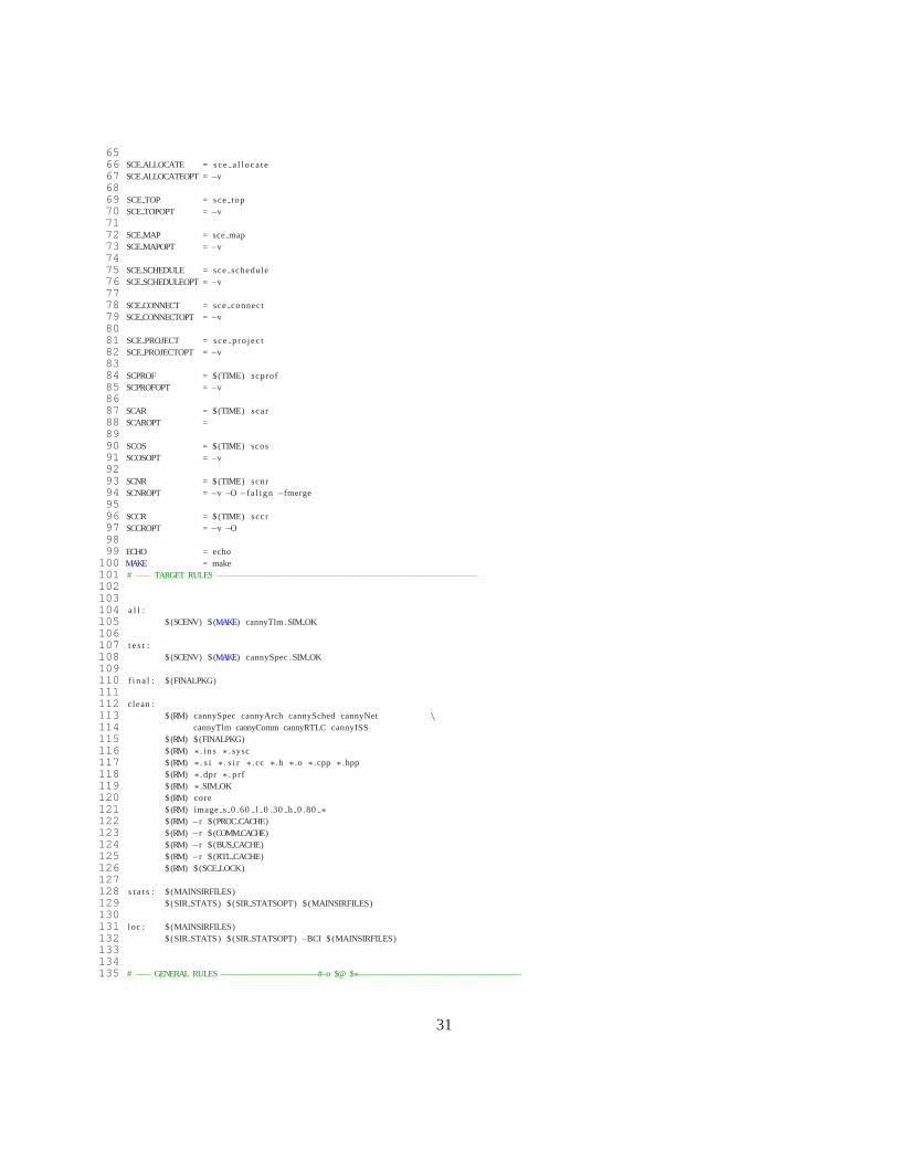
SCE tool has a graphical user interface for design space exploration.However, in order to ease theregeneration of the TLM model, a Makefile has been created. The Makefilecontains the commandsto SCE tool for different design settings and refinements.
1 #clock period for ARM CPU ( in nanoseconds )2 CPUCLKP = 1000034 #bus5 BUSCLKP = 2000067 SPECC = / opt / sce8 SCEPATH = $(SPECC)9 SCEDBPATH = $(SCEPATH) / share / sce / db10 PROCDBPATH = $(SCEDBPATH) / processors11 COMMDBPATH = $(SCEDBPATH) / communication12 BUSDBPATH = $(SCEDBPATH) / busses1314 SYSCPATH = / opt / pkg / systemc−2.1.v11516 SCENV =SPECC=$(SPECC) SCERCPATH=$$PWD/ . sce \
17 PATH=$(SPECC) / bin : $${PATH} \
18 LD LIBRARY PATH=$(SPECC) / l ib$${LD LIBRARY PATH:+:}$${LD LIBRARY PATH}192021 PROCCACHE = . sce / processors22 COMMCACHE = . sce / communication23 BUSCACHE = . sce / busses24 RTL CACHE = . sce / r t l25 SCELOCK = . sce / . scerc . lock2627 FINALPKG = f i n a l . t a r . gz2829 MAINSIRFILES = cannySpec . s i r cannyArch . s i r cannySched . si r \
30 cannyNet . s i r cannyTlm . s i r cannyComm. s i r \
31 cannyRTLC . s i r cannyISS . s i r3233 SYSC = g++−m3234 SYSCOPT =−Di38635 SYSCINC =−I$ (SYSCPATH) / inc lude36 SYSCLIB = −L$(SYSCPATH) / l ib−l inux −lsystemc3738 TIME = / usr / bin / time3940 SCC = scc41 SCCOPT =−ww −vv −d −xlx42 SCCINC =−I s r c43 SCCIMP =−Psrc44 SIRRENAME = sir rename45 SIRRENAMEOPT =−v464748 SIR STATS = s i r s t a t s49 SIR STATSOPT =5051 SIR GEN = s i r gen52 SIR GENOPT =−vv5354 SIR IMPORT = s i r impor t55 SIR IMPORTOPT =−v5657 SCSH = scsh58 SCSHOPT =5960 SCERETYPE = sceretype61 SCERETYPEOPT =−v6263 SCEIMPORT = sce import64 SCEIMPORTOPT =−v
30
6566 SCEALLOCATE = sce a l l oca te67 SCEALLOCATEOPT = −v6869 SCETOP = scetop70 SCETOPOPT =−v7172 SCEMAP = sce map73 SCEMAPOPT =−v7475 SCESCHEDULE = sceschedule76 SCESCHEDULEOPT =−v7778 SCECONNECT = sceconnect79 SCECONNECTOPT =−v8081 SCEPROJECT = scepro jec t82 SCEPROJECTOPT =−v8384 SCPROF = $(TIME) scprof85 SCPROFOPT =−v8687 SCAR = $(TIME) scar88 SCAROPT =8990 SCOS = $(TIME) scos91 SCOSOPT =−v9293 SCNR = $(TIME) scnr94 SCNROPT =−v −O −f a l i gn −fmerge9596 SCCR = $(TIME) sccr97 SCCROPT =−v −O9899 ECHO = echo
100 MAKE = make101 # −−− TARGET RULES−−−−−−−−−−−−−−−−−−−−−−−−−−−−−−−−−−−−−−−−−−−−−−−−−−−−−−−102103104 a l l :105 $(SCENV) $(MAKE) cannyTlm .SIMOK106107 t e s t :108 $(SCENV) $(MAKE) cannySpec .SIMOK109110 f i n a l : $ (FINALPKG)111112 clean :113 $(RM) cannySpec cannyArch cannySched cannyNet \
114 cannyTlm cannyComm cannyRTLC cannyISS115 $(RM) $(FINALPKG)116 $(RM) ∗. ins ∗. sysc117 $(RM) ∗. s i ∗. s i r ∗. cc ∗.h ∗.o ∗.cpp ∗.hpp118 $(RM) ∗. dpr ∗. p r f119 $(RM) ∗.SIM OK120 $(RM) core121 $(RM) image s 0 .60 l 0 .30 h 0 .80 ∗
122 $(RM) −r $ (PROCCACHE)123 $(RM) −r $ (COMMCACHE)124 $(RM) −r $ (BUSCACHE)125 $(RM) −r $ (RTL CACHE)126 $(RM) $(SCELOCK)127128 s t a t s : $ (MAINSIRFILES)129 $(SIR STATS) $(SIRSTATSOPT) $(MAINSIRFILES)130131 loc : $ (MAINSIRFILES)132 $(SIR STATS) $(SIRSTATSOPT)−BCI $(MAINSIRFILES)133134135 # −−− GENERAL RULES−−−−−−−−−−−−−−−−−−−−#−o $@ $∗−−−−−−−−−−−−−−−−−−−−−−−−−−−−−−−−−−
31

136 .SUFFIXES:137 .SUFFIXES: . ins . s i r . s i r . ins . ana . s i r138 .SUFFIXES: .pgm .SIMOK139140 . s i r . ins . s i r :141 @$(ECHO) ”∗∗∗”142 @$(ECHO) ”∗∗∗ Instrument ing $∗ fo r p ro f i l i ng . . . ”143 @$(ECHO) ”∗∗∗”144 $(SCPROF)−v −m −i $<−o $@ $∗145146 . s i r :147 @$(ECHO) ”∗∗∗”148 @$(ECHO) ”∗∗∗ Compiling $∗ fo r execut ion . . . ”149 @$(ECHO) ”∗∗∗”150 $(SCC) $∗ −s i r2ou t $ (SCCOPT) $(SCCINC) $(SCCIMP)151152 . ins . s i r . ins :153 @$(ECHO) ”∗∗∗”154 @$(ECHO) ”∗∗∗ Compiling $∗ fo r execut ion with p ro f i l i ng . . . ”155 @$(ECHO) ”∗∗∗”156 $(SCC) $∗ −s i r2ou t $ (SCCOPT) $(SCCINC)$(SCCIMP)−i $<−o $@−l scp ro f157158 .pgm.SIMOK:159 @$(ECHO) ”∗∗∗”160 @$(ECHO) ”∗∗∗ Simulat ing $∗”161 @$(ECHO) ”∗∗∗”162 $(TIME) . / $∗. ins | tee log execut ion $∗163 @$(ECHO) ”∗∗∗”164 @$(ECHO) ”∗∗∗ Simulat ion successfu l ! ”165 @$(ECHO) ”∗∗∗”166167 . s i r . ana . s i r :168 @$(ECHO) ”∗∗∗”169 @$(ECHO) ”∗∗∗ Back−annotat ing p ro f i l i ng data and running est imat ion . . . ”170 @$(ECHO) ”∗∗∗”171 $(SCPROF)−E $(SCPROFOPT)−i $<−o $@ $∗172173 # −−− SPECIFIC RULES−−−−−−−−−−−−−−−−−−−−−−−−−−−−−−−−−−−−−−−−−−−−−−−−−−−−−174175 # −−− compile the sources176 cannySpecpre . s i r : canny . sc177 @$(ECHO) ”∗∗∗”178 @$(ECHO) ”∗∗∗ Compiling the sources . . . ”179 @$(ECHO) ”∗∗∗”180 $(SCC) canny−sc2s i r $ (SCCOPT) $(SCCINC) $(SCCIMP)\
181 −i canny . sc −o cannySpecpre . s i r182183 cannySpec . s i r : cannySpecpre . s i r184 @$(ECHO) ”∗∗∗”185 @$(ECHO) ”∗∗∗ Set t ing top leve l of design under t e s t . . . ”186 @$(ECHO) ”∗∗∗”187 $(SCETOP) $(SCETOPOPT)−s Platform \
188 −i cannySpecpre . s i r−o cannySpec . s i r cannySpec189190 cannySpec . ins . s i r : cannySpec . s i r191 cannySpec : cannySpec . s i r192 cannySpec . ins : cannySpec . ins . s i r193 cannySpec .pgm: cannySpec . ins194 cannySpec .SIMOK: cannySpec .pgm195 cannySpec . ana . s i r : cannySpec . s i r cannySpec .SIMOK196197 # −−− back−annotate raw pro f i l i ng data198 cannySpec . prof . s i r : cannySpec . s i r cannySpec .SIMOK199 @$(ECHO) ”∗∗∗”200 @$(ECHO) ”∗∗∗ Back−annotat ing raw pro f i l i ng data . . . ”201 @$(ECHO) ”∗∗∗”202 $(SCPROF)−p $(SCPROFOPT)−i cannySpec . s i r−o cannySpec . prof . s i r cannySpec203204 cannySpec . 3 . s i r : cannySpec . prof . s i r205 @$(ECHO) ”∗∗∗”206 @$(ECHO) ”∗∗∗ Al locat ing the component . . . ”
32
207 @$(ECHO) ”∗∗∗”208 $(SCEALLOCATE) $(SCEALLOCATEOPT)\209 −g PORTAHCLK PERIOD=$(BUSCLKP)−g CLOCKPERIOD=$(CPUCLKP)−p CPU=ARM7TDMI\210 −g CLOCKPERIOD=−p IO OUT=HW Virtual \
211 −g CLOCKPERIOD=−p IO IN=HW Virtual \
212 −g CLOCKPERIOD=−p HardwareBlurX=HW Standard\213 −g CLOCKPERIOD=−p HardwareBlurY=HW Standard\214 −i cannySpec . prof . s i r−o cannySpec . 3 . s i r cannySpec215216 cannySpec . 4 . s i r : cannySpec . 3 . s i r217 @$(ECHO) ”∗∗∗”218 @$(ECHO) ”∗∗∗ Map the components . . ”219 @$(ECHO) ”∗∗∗”220 $(SCEMAP) $(SCEMAPOPT) −p Platform . canny=CPU\221 −p Platform . din=IOIN \
222 −p Platform . dout=IOOUT \
223 −p Platform . canny . gaussiansmooth . blurY par=HardwareBlurY\
224 −p Platform . canny . gaussiansmooth . blurX par=HardwareBlurX\
225 −i cannySpec . 3 . s i r−o cannySpec . 4 . s i r cannySpec226227 # −−− analyze the p ro f i l e given the behavior mapping228 cannySpec . ana1 . s i r : cannySpec . 4 . s i r229 @$(ECHO) ”∗∗∗”230 @$(ECHO) ”∗∗∗ Analyzing the behavior mapping . . . ”231 @$(ECHO) ”∗∗∗”232 $(SCPROF)−a $(SCPROFOPT)−i cannySpec . 4 . s i r\233 −o cannySpec . ana1 . s i r canny234235 # −−− est imate the p ro f i l e given the behavior mapping236 cannySpec . ana2 . s i r : cannySpec . 4 . s i r237 @$(ECHO) ”∗∗∗”238 @$(ECHO) ”∗∗∗ Estimat ing the behavior mapping . . . ”239 @$(ECHO) ”∗∗∗”240 $(SCPROF)−e $(SCPROFOPT)−i cannySpec . 4 . s i r\241 −o cannySpec . ana2 . s i r canny242243 cannySpec . arch . in . s i r : cannySpec . ana2 . s i r cannySpec . ana1 . s i r244 @$(ECHO) ”∗∗∗”245 @$(ECHO) ”∗∗∗ Importing the PEs in to the design . . . ”246 @$(ECHO) ”∗∗∗”247 $(SCEIMPORT) $(SCEIMPORTOPT) −a \
248 −i cannySpec . ana2 . s i r−o cannySpec . arch . in . s i r\249 cannySpec250251 cannyArch . s i r : cannySpec . arch . in . s i r252 @$(ECHO) ”∗∗∗”253 @$(ECHO) ”∗∗∗ Performing a rch i t ec tu re ref inement . . . ”254 @$(ECHO) ”∗∗∗”255 $(SCAR) cannySpec−b −m −c −w $(SCAROPT) \256 −i cannySpec . arch . in . s i r−o cannySpec . arch . s i r257 $(SIRRENAME) $(SIRRENAMEOPT) −i cannySpec . arch . s i r\258 cannySpec cannyArch259 $(SIR STATS) $(SIRSTATSOPT) $@260261 cannyArch . ins . s i r : cannyArch . s i r262 cannyArch . ins : cannyArch . ins . s i r263 cannyArch .pgm: cannyArch . ins264 cannyArch .SIMOK: cannyArch .pgm265 cannyArch . ana . s i r : cannyArch . s i r cannyArch .SIMOK266267 cannyArch . 2 . s i r : cannyArch . ana . s i r268 @$(ECHO) ”∗∗∗”269 @$(ECHO) ”∗∗∗ Deciding schedul ing . . . ”270 @$(ECHO) ”∗∗∗”271 $(SCESCHEDULE) $(SCESCHEDULEOPT)−r −t Platform\272 −k CPU=ARM7TDMI OSNONE$(CPUCLKP) $ (BUSCLKP) 0 \
273 −i cannyArch . ana . s i r−o cannyArch . 2 . s i r cannyArch274275 # −−− import components for schedul ing ref inement276 cannyArch . sched . in . s i r : cannyArch . 2 . s i r277 @$(ECHO) ”∗∗∗”
33

278 @$(ECHO) ”∗∗∗ Importing componentsneeded for schedul ing . . . ”279 @$(ECHO) ”∗∗∗”280 $(SCEIMPORT) $(SCEIMPORTOPT) −s \
281 −i cannyArch . 2 . s i r−o cannyArch . sched . in . s i r\282 cannyArch283284 # −−− perform s t a t i c schedul ing ref inement285 cannyArch . sched . tmp . s i r : cannyArch . sched . in . s i r286 @$(ECHO) ”∗∗∗”287 @$(ECHO) ”∗∗∗ Performing s t a t i c schedul ing ref inement . . . ”288 @$(ECHO) ”∗∗∗”289 $(SCAR) cannyArch $(SCAROPT)−s \
290 −i cannyArch . sched . in . s i r−o cannyArch . sched . tmp . s i r291292 # −−− perform dynamic schedul ing ref inement293 cannySched . s i r : cannyArch . sched . tmp . s i r294 @$(ECHO) ”∗∗∗”295 @$(ECHO) ”∗∗∗ Performing dynamic schedul ing ref inement . . . ”296 @$(ECHO) ”∗∗∗”297 $(SCOS) cannyArch $(SCOSOPT)\298 −i cannyArch . sched . tmp . s i r−o cannyArch . sched . s i r299 $(SIRRENAME) $(SIRRENAMEOPT) −i cannyArch . sched . s i r\300 cannyArch cannySched301 $(SIR STATS) $(SIRSTATSOPT) $@302303 cannySched . ins . s i r : cannySched . s i r304 cannySched . ins : cannySched . ins . s i r305 cannySched .pgm: cannySched . ins306 cannySched .SIMOK: cannySched .pgm307 cannySched . ana . s i r : cannySched . s i r cannySched .SIMOK308309310 cannySched . 2 . s i r : cannySched . ana . s i r311 @$(ECHO) ”∗∗∗”312 @$(ECHO) ”∗∗∗ Al locat ing the CPU bus and the Hardware Bus . . . ”313 @$(ECHO) ”∗∗∗”314 $(SCEALLOCATE) $(SCEALLOCATEOPT) \
315 −b CPUBus=AMBAAHB \
316 −b HW Bus=HardwareBus\317 −i cannySched . ana . s i r−o cannySched . 2 . s i r cannySched318319 # −−− connect the PE and the busses320 cannySched . 3 . s i r : cannySched . 2 . s i r321 @$(ECHO) ”∗∗∗”322 @$(ECHO) ”∗∗∗ ConnectingPE and the busses . . . ”323 @$(ECHO) ”∗∗∗”324 $(SCECONNECT) $(SCECONNECTOPT)−c CPU, PortA=CPUBus , master0\325 −c HardwareBlurX , Port0=CPUBus , slave4−c HardwareBlurX , Port1=HWBus, Master\326 −c HardwareBlurY , Port0=CPUBus , slave5−c HardwareBlurY , Port1=HWBus, Slave\327 −c IO OUT, Port0=CPUBus , slave8\328 −c IO IN , Port0=CPUBus , slave7\329 −i cannySched . 2 . s i r−o cannySched . 3 . s i r cannySched330331 # −−− import components for network ref inement332 cannySched . net . in . s i r : cannySched . 3 . s i r333 @$(ECHO) ”∗∗∗”334 @$(ECHO) ”∗∗∗ Importing componentsneeded for network ref inement . . . ”335 @$(ECHO) ”∗∗∗”336 $(SCEIMPORT) $(SCEIMPORTOPT) −e \
337 −i cannySched . 3 . s i r−o cannySched . net . in . s i r\338 cannySched339340 # −−− perform network ref inement341 cannyNet . s i r : cannySched . net . in . s i r342 @$(ECHO) ”∗∗∗”343 @$(ECHO) ”∗∗∗ Performing network ref inement . . . ”344 @$(ECHO) ”∗∗∗”345 $(SCNR) cannySched $(SCNROPT)\346 −i cannySched . net . in . s i r−o cannySched . net . s i r347 $(SIRRENAME) $(SIRRENAMEOPT) −i cannySched . net . s i r\348 cannySched cannyNet
34
349 $(SIR STATS) $(SIRSTATSOPT) $@350351 cannyNet . ins . s i r : cannyNet . s i r352 cannyNet . ins : cannyNet . ins . s i r353 cannyNet .pgm: cannyNet . ins354 cannyNet .SIMOK: cannyNet .pgm355 cannyNet . ana . s i r : cannyNet .SIMOK cannyNet . s i r356357 # −−− def ine the l ink parameters358 cannyNet . 2 . s i r : cannyNet . ana . s i r359 @$(ECHO) ”∗∗∗”360 @$(ECHO) ”∗∗∗ Defining the l ink parametersfor the busses . . . ”361 @$(ECHO) ”∗∗∗”362 $(SCEMAP) $(SCEMAPOPT) −l c link IO IN CPU=0x70000000 ,0\363 −l c link CPU IO OUT=0x80000000,0\364 −l c link CPU HardwareBlurX=0x40000000,0\365 −l c link CPU HardwareBlurY=0x50000000,0\366 −l c l ink HardwareBlurX HardwareBlurY=0x0000 , MasterSync0\367 −i cannyNet . ana . s i r−o cannyNet . 2 . s i r cannyNet368369 # −−− import the busses in to the design370 cannyNet .comm. in . s i r : cannyNet . 2 . s i r371 @$(ECHO) ”∗∗∗”372 @$(ECHO) ”∗∗∗ Importing the busses in to the design . . . ”373 @$(ECHO) ”∗∗∗”374 $(SCEIMPORT) $(SCEIMPORTOPT) −c \
375 −i cannyNet . 2 . s i r−o cannyNet .comm. in . s i r\376 cannyNet377378 # −−− perform communication ref inement to TLM379 cannyTlm . s i r : cannyNet .comm. in . s i r380 @$(ECHO) ”∗∗∗”381 @$(ECHO) ”∗∗∗ Performing communication ref inement to TLM. . . ”382 @$(ECHO) ”∗∗∗”383 $(SCCR) cannyNet $(SCCROPT)−t \
384 −i cannyNet .comm. in . s i r−o cannyNet .comm. s i r385 $(SIRRENAME) $(SIRRENAMEOPT) −i cannyNet .comm. s i r\386 cannyNet cannyTlm387 $(SIR STATS) $(SIRSTATSOPT) $@388389 cannyTlm . ins . s i r : cannyTlm . s i r390 cannyTlm . ins : cannyTlm . ins . s i r391 cannyTlm .pgm: cannyTlm . ins392 cannyTlm .SIMOK: cannyTlm .pgm393 cannyTlm . ana . s i r : cannyTlm .SIMOK cannyTlm . s i r
35