system identification of rotorcraft rebecca creed, mechanical engineering, university of dayton...
TRANSCRIPT
1
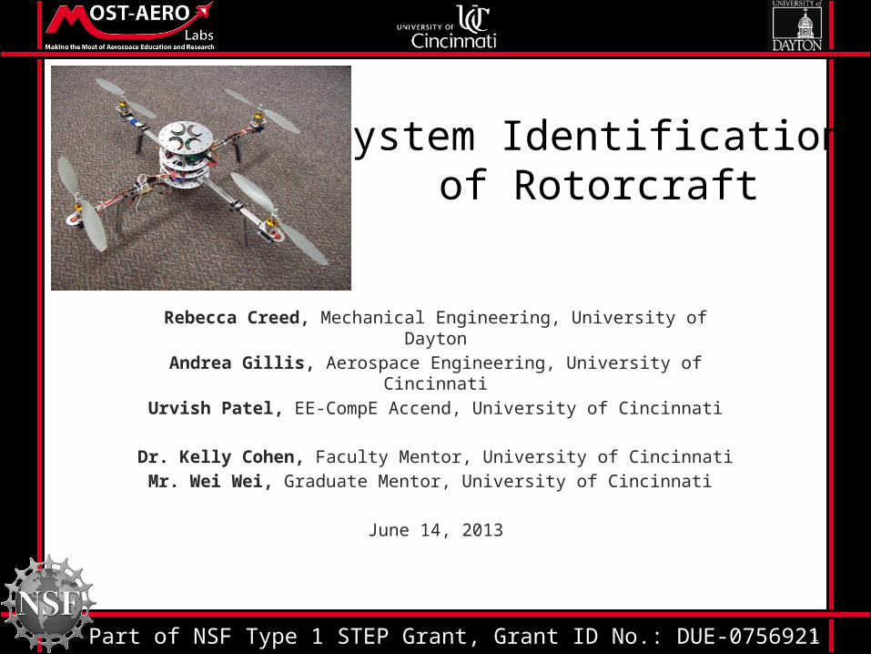
System Identification of Rotorcraft
Rebecca Creed, Mechanical Engineering, University of DaytonAndrea Gillis, Aerospace Engineering, University of Cincinnati
Urvish Patel, EE-CompE Accend, University of Cincinnati
Dr. Kelly Cohen, Faculty Mentor, University of CincinnatiMr. Wei Wei, Graduate Mentor, University of Cincinnati
June 14, 2013
Part of NSF Type 1 STEP Grant, Grant ID No.: DUE-0756921

2
Introduction• Natural disasters take thousands of lives
every year. • Many first responders perform dangerous
rescue missions to save lives.• Technology will allow first responders to
assess the situation more quickly and efficiently.

3
Image courtesy of CNN
Oklahoma Fire Fighters Rescue Tornado Victims from Rubble
Date: May 22, 2013Rescued: 101 peopleLives Lost: 24 peopleLength of Search: ~ 48 hrs
• Rotorcrafts equipped with heat sensors and cameras will reduce the length of searches.
• Shorter searches will hopefully reduce the lives lost.
2013 Oklahoma Tornado

4
2012 Colorado Wildfire• The progression of the fire could not be
anticipated.• Once the fire had become an issue, the best
way to access it was unknown.• An autopilot equipped rotorcraft would be able to use a camera and assess the situation.
Image courtesy of csmonitor.com

5
Why Autopilot?• Easy to use with simple controls• Increase the range of the rotorcraft– Without autopilot, the rotorcraft must remain in
the operator’s line of sight• A dynamic model is necessary to develop an
autopilot

6
System Identification• A dynamic model is a representation of the
behavior of a system (for this case, rotorcraft)• Two options for creating a dynamic model– System Identification– Wind Tunnel Testing
7
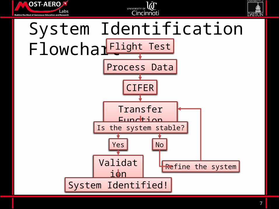
System Identification FlowchartFlight Test
Process Data
CIFER
Transfer Function
Validation
Is the system stable?
Yes No
Refine the system
System Identified!

8
Flight Test• Inputs will be given to the rotorcraft• Outputs will be recorded

Process Data
9
Sensor stick used in
Rotorcraft – 9DOF
Accelerometer ADXL345
Noisy Data
Picture from: www.sparkfun.com
Filtered Data
FilterNext Step

10
Kalman Filter for Linear System• x = x• p = p + q;• k = p / (p + r);• x = x + k * (measured – x);• p = (1 – k) * p;
x = filtered value p = estimated error q = processed noice r = Sensor Noise k = kalman gain
Kalaman Predictor Equation
Measurement Update Equation

11
Result from Kalman Filter
-1.2
-1
-0.8
-0.6
-0.4
-0.2
0
0.2
0.4
0.6
X axis
RegularKalman

12
Moving average• Almost same result as kalman filter for our
system. • Only disadvantage is it takes sometime to
start averaging data.

13
Results of Moving average
-6
-4
-2
0
2
4
6
X axis
RegularMoving average

14
Moving average and Kalman
-2
-1.5
-1
-0.5
0
0.5
1
1.5
X axis
RegularKalmanMoving average
15
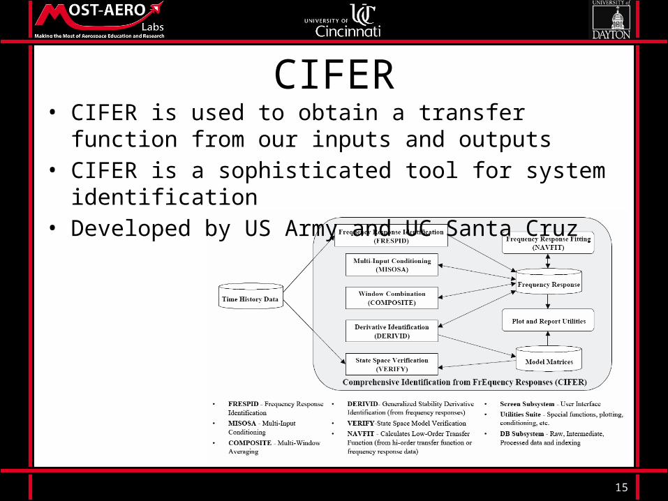
CIFER• CIFER is used to obtain a transfer function from our inputs
and outputs• CIFER is a sophisticated tool for system identification• Developed by US Army and UC Santa Cruz

Flight Training• Flight Simulator
o Learned how to use controlso The team practiced using this first
• AR Parrot Droneo Used because of its durabilityo Emergency landing capabilities
• Importanceo Ensure accurate resultso Inputs need to be purposeful
to receive clear outputs
17
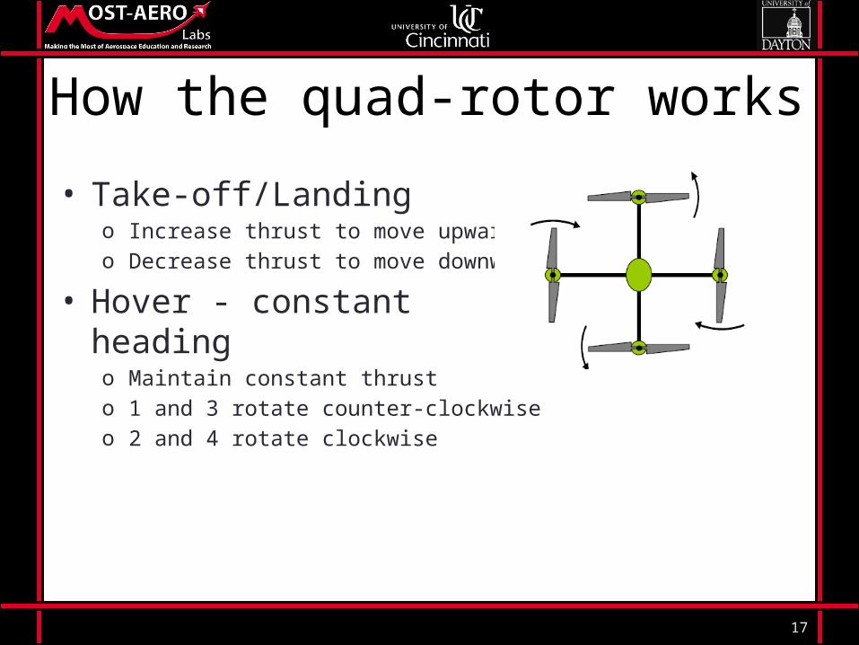
How the quad-rotor works
• Take-off/Landingo Increase thrust to move upwardo Decrease thrust to move downward
• Hover - constant headingo Maintain constant thrusto 1 and 3 rotate counter-clockwiseo 2 and 4 rotate clockwise

18
How the quad-rotor works• Yaw Control – spin cw/counter-cw
o 1 and 3 speed up or 2 and 4 slow downo Reverse for other direction
• Pitch Control – move forward/backwardo 4 rotates faster while 2 stays the same or 2 moves slowero Reverse for other direction
• Roll Control – move right/lefto 3 moves faster while 1 stays the same or 1 slows downo Reverse for other direction
Pitch RollYaw
UAV Advantages• Maneuverability• Cost• Endurance• Safer for Crews• Size• Indoor Flight• Sushi Delivery
Image courtesy of http://www.todaysiphone.com/2013/06/yo-sushi-delivering-food-on-ipad-controlled-trays/

20
TimelineWeek 1 2 3 4 5 6 7 8
Literature and technical Review
Learn how to fly AR Drone
Flight testing
Data Processing
System Identification
Document Findings

21
References• Bestaoui, Y., and Slim, R. (2007). “Maneuvers for a Quad-Rotor Autonomous Helicopter,” AIAA Infotech@Aerospace Conference, held
at Rohnert Park, California, May 7-10, pp.1-18
• Chen, M., and Huzmezan, M. (2003). “A Combined MBPC/2 DOF H∞ Controller for a Quad Rotor UAV,” AIAA Guidance, Navigation,
and Control Conference and Exhibit, held at Austin, Texas, August 11-14, n.p.
• Esme, B. (2009). “Kalman Filter For Dummies.” Biligin’s Blog, <http://bilgin.esme.org/BitsBytes/KalmanFilterforDummies.aspx> (Mar.
2009).
• Guo, W., and Horn, J. (2006). “Modeling and Simulation For the Development of a Quad-Rotor UAV Capable of Indoor Flight ,” AIAA
Modeling and Simulation Technologies Conference, held at Keystone, Colorado, August 21-24, pp.1-11
• Halaas, D., Bieniawski, S., Pigg, P., and Vian, J. (2009). “Control and Management of an Indoor Health Enabled, Heterogenous Fleet,”
AIAA Infotech@Aerospace Conference, held at Seattle, Washington, April 6-9, pp.1-19

22
References• Koehl, A., Rafaralahy, H., Martinez, B., and Boutayeb, M. (2010). “Modeling and Identification of a Launched Micro Air Vehicle: Design and
Experimental Results,” AIAA Modeling and Simulation Technologies Conference, held at Toronto, Ontario Canada, August 2-5, pp.1-18
• Mehra, R., Prasanth, R., Bennett, R., Neckels, D., and Wasikowski, M. (2001). “Model Predictive Control Design for XV-15 Tilt Rotor Flight
Control,” AIAA Guidance, Navigation, and Control Conference and Exhibit, held at Montreal, Canada, August 6-9, pp. 1-11.
• Milhim, A., and Zhang, Y. (2010). “Quad-Rotor UAV: High-Fidelity Modeling and Nonlinear PID Control,” AIAA Modeling and Simulation
Technologies Conference, held at Toronto, Ontario, Canada, August 2-5, pp. 1-10.
• Salih, A., Moghavvemi, M., Mohamed, H., and Gaeid, K. (2010). “Flight PID controller design for a UAV quadrotor,” Scientific Research and
Essays, ????, Vol. 5, No. 23, pp. 3660-3667.
• Tischler, M.B., and Cauffman, M.G. (2013). “Frequency-Response Method for Rotorcraft System Identification: Flight Applications to BO-105
Coupled Fuselage/Rotor Dynamics,” University Affiliated Research Center: A Partnership Between UCSC and NASA Ames Research Center,
pp. 1-13.

23
Questions?