system functional overview - dynon certified
TRANSCRIPT

SkyView
System Functional Overview
STC SA02594SE
103014-000
Revision B
8/4/2020
Copyright © 2020 by Dynon Avionics, Inc.
Dynon Avionics grants third parties' permission to print this document

Contact Information
Dynon Avionics, Inc.
19825 141st Place NE
Woodinville, WA 98072
Phone: 425-402-0433
Business Operations: 8:00 AM–5:00 PM (Pacific Time) Monday–Friday
Technical Support Operations: 7:30 AM–4:00 PM (Pacific Time) Monday–Friday
Email Sales: [email protected]
Email Support: [email protected]
Web: www.dynoncertified.com
Copyright
©2020 Dynon Avionics, Inc. All rights reserved. No part of this manual may be reproduced, copied, transmitted, disseminated or stored in any
storage medium, for any purpose without the express written permission of Dynon Avionics. Dynon Avionics hereby grants permission to
download a single copy of this manual and of any revision to this manual onto a hard drive or other electronic storage medium to be viewed for
personal use, provided that such electronic or printed copy of this manual or revision must contain the complete text of this copyright notice and
provided further that any unauthorized commercial distribution of this manual or any revision hereto is strictly prohibited.
Information in this document is subject to change without notice. Dynon Avionics reserves the right to change or improve its products and to
make changes in the content without obligation to notify any person or organization of such changes. Visit the Dynon Avionics website
(www.dynonavionics.com) for current updates and supplemental information concerning the use and operation of this and other Dynon Avionics
products.

SkyView HDX System Functional Overview - STC SA02594SE, Revision B Page | i
Revision History
REV DATE APPROVED DESCRIPTION OF CHANGE
A 1/5/2018 Initial Release
B 8/4/2020 ECO # 339864 • Changed title of document to System Functional Overview.
• Applied new template and style guide standards to document.
• Restructured document to reflect integrated system strategy.
• Updated all content in all sections to reflect the latest system behavior and configurations.

Page | ii SkyView HDX System Functional Overview - STC SA02594SE, Revision B
Table of Contents
1 Introduction .................................................................................................. 4
1.1 Intended Audience ........................................................................................................ 4
1.2 Reference Documents .................................................................................................. 4
2 SkyView HDX System .................................................................................. 5
2.1 SkyView HDX Displays ................................................................................................. 5
2.2 Flight Crew Alerting System ......................................................................................... 9
2.3 System of Systems ..................................................................................................... 11
3 Primary Flight Information System.......................................................... 12
3.1 System Equipment ..................................................................................................... 13
3.2 System Functions and Controls .................................................................................. 17
4 Navigation System .................................................................................... 20
4.1 System Equipment ..................................................................................................... 21
4.2 System Functions and Controls .................................................................................. 21
5 Engine Monitoring System ....................................................................... 23
5.1 System Equipment ..................................................................................................... 23
5.2 System Functions and Controls .................................................................................. 24
6 Autopilot System ....................................................................................... 27
6.1 System Equipment ..................................................................................................... 27
6.2 System Functions and Controls .................................................................................. 30
7 Communication System ............................................................................ 33
7.1 System Equipment ..................................................................................................... 33
7.2 System Functions and Controls .................................................................................. 34
8 Transponder System ................................................................................. 36
8.1 System Equipment ..................................................................................................... 36
8.2 System Functions and Controls .................................................................................. 37
9 IFR Navigation Integration System .......................................................... 38
9.1 System Equipment ..................................................................................................... 38
9.2 System Functions and Controls .................................................................................. 38
10 Traffic and Weather Information System ................................................ 39
10.1 System Equipment ..................................................................................................... 39

SkyView HDX System Functional Overview - STC SA02594SE, Revision B Page | iii
10.2 System Functions and Controls .................................................................................. 40
11 Angle of Attack Indicating System .......................................................... 44
11.1 System Equipment ..................................................................................................... 44
11.2 System Functions and Controls .................................................................................. 44
12 Supporting Equipment .............................................................................. 45
12.1 SV-KNOB-PANEL Knob Control Panel ...................................................................... 45
12.2 SV-NET-HUB Network Hub ........................................................................................ 45
12.3 Panel Mount USB Port ............................................................................................... 46
13 Appendix 1: Glossary ................................................................................ 47

Page | 4 SkyView HDX System Functional Overview - STC SA02594SE, Revision B
1 Introduction
The purpose of this document is to provide the reader with a quick overview of the SkyView HDX
system and its components and functions.
Refer to the SkyView HDX Airplane Flight Manual Supplement document for operational
information, refer to the SkyView HDX Installation Manual document for installation and
configuration information, and refer to SkyView HDX General Maintenance Manual document
for diagnostic and service information.
1.1 Intended Audience
This document is intended for any Airplane Owner, Pilot, Installer, or Maintainer that is new to
SkyView HDX and wants to learn more about the basic operation and system architecture.
1.2 Reference Documents
• 103261-001 SkyView HDX System Installation Manual
• 103272-000 SkyView HDX System Airplane Flight Manual Supplement
• 103221-000 SkyView HDX System General Maintenance Manual

SkyView HDX System Functional Overview - STC SA02594SE, Revision B Page | 5
2 SkyView HDX System
SkyView HDX is an integrated Electronic Flight Instrument System (EFIS) that can aggregate
flight, engine, navigation, traffic, and weather information for presentation to the pilot on a
SkyView HDX display.
2.1 SkyView HDX Displays
The most integral component of the SkyView HDX system is the SkyView HDX display (see
Figure 1). SkyView HDX displays are multi-functional, high-definition, LCD color displays that
process data inputs to generate graphical representations of flight instrumentation and other
aircraft information on- screen. SkyView HDX displays use LED backlighting technology for
increased lifespan, more uniform brightness, and superior dimming control.
Pilots interact with system functions through the SkyView HDX display. The system functions
available to the pilot are dependent upon the systems (major and ancillary) installed as part of
the SkyView HDX system. Major systems require the installation of at least one display to
function. Up to three SkyView HDX displays, in any combination of the two sizes, can be installed
in the airplane’s instrument panels.
SkyView HDX displays are available in two sizes:
• the SV-HDX1100 is a 10.1-inch, 1280 x 800-pixel display,
• the SV-HDX800 is a 7.1-inch, 1280 x 800-pixel display.
Figure 1: SV-HDX1100 and SV-HDX800 Displays

Page | 6 SkyView HDX System Functional Overview - STC SA02594SE, Revision B
The structure surrounding the lighted LCD screen is referred to as the bezel. All tactile controls
for the system are located on the tilted shelf at the bottom of the bezel, or on the screen itself.
Pilot interaction with the display using two knobs with buttons on the sides of the bezel, eight
buttons along the bottom of the bezel, and by pressing touchable screen items. There is also a
light sensor that is used for automatic screen brightness control.
A SkyView HDX display screen contains three main regions, described from top to bottom:
• The Top Bar is located on the top of the screen. It is configurable and presents important
airplane information, including time or a timer (when running), Autopilot status, backup
battery status, COM radio frequency, and transponder status.
• The main portion of the screen (i.e., main screen) is configurable and can present Primary
Flight Display (PFD), Map, and Engine Monitoring System (EMS) information. It can also
present the system alerts and messages, function control menus, and configuration
menus.
• The Button Bar is located on the bottom of the screen. It is displayed when the system
is fully powered-on. It presents knob and button soft labels. Knob and button
functionality are contextual, depending upon what is presented on the screen. Labels will
always show the current function.
Display layout options are selected by pressing the DISPLAY button. The pilot then selects
whether the display should present PFD, Map, or EMS information, or a combination thereof.
Information can be presented in 100%-page layouts, 50%-page layouts, and a bottom band
layout. See Figure 2 for PFD, Map, and EMS configured for 50% page layout with bottom band;
see Figure 3 for PFD configured for 100% page layout.
Figure 2: 50% PFD and Map Page Layout with EMS Bottom Band.

SkyView HDX System Functional Overview - STC SA02594SE, Revision B Page | 7
2.1.1 Controls
SkyView HDX displays have knobs and buttons to control various functions, including powering
the display ON and OFF, accessing and navigating menus, selecting, or activating features, and
adjusting values.
Figure 3: SkyView HDX Display Controls
Buttons generally require a single action (i.e., momentarily press). Pressing the button will
provide a distinct tactile "click" response to the pilot. The click occurs when the button is fully
pressed, but the action does not occur until the button is released. When a button is pressed in
this manner, a function or action denoted by the label above the button is invoked. Button
labels are contextual and may change depending on the menus and feature control pages
the pilot selects.
Figure 4: Knob Rotation and Button Push Actions
A button has a function if a label is displayed above it. If there is no label, then no function is
available. Some buttons have additional behavior when the button is pressed and held down for
two seconds. An example is Button #1. When you press-and-hold Button #1, the SkyView HDX
display will power ON/OFF. Additional press-and-hold behaviors for other buttons are described
in the SkyView HDX Airplane Flight Manual Supplement document.

Page | 8 SkyView HDX System Functional Overview - STC SA02594SE, Revision B
Knobs rotate in both directions and can be pushed. The current knob function is indicated by the
label above the knob. Knob function is contextual and can change when the content of the screen
is changed by the pilot.
On some menu pages with both vertical lists and a horizontal group of tabs, one or both knobs
have a "push and rotate" behavior, which controls horizontal scrolling of the cursor across rows
and columns.
2.1.2 Functions
A SkyView HDX display has a Function Control Menu (i.e., Menu) for controlling various system
functions (see Figure 5). To access the menu, press the MENU button (Button #6). The icons in
menu are tactile and touching them opens a Control Page for the function. For example, touching
the COM RADIO icon opens its Control Page. There are also shortcut icons on the Top Bar for
Autopilot, COM Radio, and Transponder functions. Information about using function controls is
available in the SkyView HDX Airplane Flight Manual Supplement document.
Figure 5: Function Control Menu (Menu) with Optional Systems Installed

SkyView HDX System Functional Overview - STC SA02594SE, Revision B Page | 9
2.2 Flight Crew Alerting System
The Flight Crew Alerting System is a central feature of the SkyView HDX system. This system
provides the pilot and crew with system information organized by priority for all installed SkyView
HDX sub-systems. The alerts and messages will vary depending upon the installed equipment.
This section describes all possible alerts and messages.
System information is delivered in the form of flight crew Alerts and Messages that are organized
by severity into one of three categories:
1. Warning Alerts:
• Time-Critical Warning Alerts are used for flight-path related conditions that require
immediate flight crew awareness and immediate flight crew response. Because these
alert conditions are flightpath related, the messages appear on the Primary Flight
Display.
• Warning Alerts are for non-flightpath conditions that require immediate flight crew
awareness and immediate flight crew response.
2. Caution Alerts:
• Caution Alerts are used for conditions that require immediate flight crew awareness
and subsequent flight crew response.
3. Messages:
• Messages are used for conditions that require immediate flight crew awareness and
may require subsequent flight crew response.
2.2.1 Notification Methods
Whenever a new non-flightpath alert is generated, the Alert Notification Indicator (i.e., soft key
label) shown in Figure 6, flashes Red for Warning alerts, Amber for Caution alerts, and Gray for
Messages. A corresponding voice aural annunciates. The annunciation is typically a spoken
word like "WARNING" or "CAUTION" if the alert is a Warning or Caution. For engine-related
Warnings, a specific voice aural annunciation like "OIL PRESSURE" can be configured.
Figure 6: Warning Notification Indication
Pressing Button #8 will open the Alert Notification Window. This window displays text associated
with each active alert. After pressing Button #8, the alerts present in the window are considered
acknowledged and the Message Notification Indicator stops flashing. The Message Notification
Indicator color corresponds with highest alert level remaining active.
The appearance of alerts within the Alert Notification Window change when first activated and
after acknowledgement. The difference between an un-acknowledged and acknowledged

Page | 10 SkyView HDX System Functional Overview - STC SA02594SE, Revision B
message is shown in Figure 7. This difference is consistent with all alerts, regardless of color.
When no alerts are active, the Alert Indicator states, "NO MSG".
Figure 7: Message Notification Window, Message Appearance

SkyView HDX System Functional Overview - STC SA02594SE, Revision B Page | 11
2.3 Integrated System
The Skyview HDX system can integrate three different major systems (see Section 2.3.1) and
six ancillary systems (see Section 2.3.2). Systems can be combined per need and preference
to provide a wide array of functions and present useful aircraft information to the pilot.
The SkyView HDX system is centered around the SkyView HDX display. Up to three displays
may be installed in a SkyView HDX system. At least one display is required for installation of a
major system. A single display can present all information from and provide access to all
functions associated with the major and ancillary systems.
Third-party equipment can also integrate with the Skyview HDX system. NAV radio receivers,
IFR GPS Navigators, position-reporting ELT transmitters, and COM transmitters are commonly
integrated with the Skyview HDX system. Devices using the RS-232 protocol can connect
directly to the SkyView HDX system, while ARINC-429 Navigators require the installation of the
IFR Navigation Integration System.
It is important to note that certain requirements must be met to ensure a regulatory-compliant
Primary Flight Information (PFI) system installation. If the SkyView HDX system is not being
used to provide PFI, installation compliance, like placement of a Skyview HDX display, becomes
less critical. Design guidance and requirements for a compliant installation are described in the
SkyView HDX Installation Manual.
2.3.1 Major Systems
The following major systems can be integrated into the Skyview HDX system:
• Primary Flight Information System (see Section 3),
• Navigation System (see Section 4),
• Engine Monitoring System (see Section 5).
2.3.2 Ancillary Systems
The following ancillary systems can be integrated into the Skyview HDX system with some
limitations:
• Autopilot System (see Section 6),
• Communication System (see Section 7),
• Transponder System (see Section 8),
• IFR Navigation Integration System (see Section 9),
• Traffic and Weather Information System (see Section 10),
• Angle of Attack Indicating System (see Section 11).

Page | 12 SkyView HDX System Functional Overview - STC SA02594SE, Revision B
3 Primary Flight Information System
The Primary Flight Information (PFI) system replaces the analog instruments that have
traditionally provided PFI. SkyView HDX's PFI provides much more functionality than traditional
analog instruments. All PFI functions are provided to the pilot on SkyView HDX display in a
standard Primary Flight Display (PFD) format (see Figure 8). The PFI can also be presented in
the traditional "Six-Pack" format (see Figure 9).
Figure 8: Primary Flight Display (PFD) Format
Figure 9: "Six Pack" Display Format

SkyView HDX System Functional Overview - STC SA02594SE, Revision B Page | 13
3.1 System Equipment
The following is the minimum equipment required to provide PFI functionality:
• At least one – SV-HDX800 or SV-HDX1100 display (see Section 2.1),
• One per display – SV-BAT-320 backup battery (see Section 3.1.1),
• One – Standby Flight Information System (see Section 3.1.2),
• One – SV-ADAHRS-200 ADAHRS module (see Section 3.1.3),
• One – SV-MAG-236 remote magnetometer (see Section 3.1.4),
• One – Outside Air Temperature (OAT) sensor (see Section 3.1.5),
• One – SV-GPS-2020 WAAS GPS antenna/receiver (see Section 3.1.6).
3.1.1 SV-BAT-320 Backup Battery
If avionics power is lost in flight, a properly operating SV-BAT-320 backup battery (see Figure
10) can provide power to a SkyView HDX display and other SkyView components to keep critical
functions like Primary Flight Information (PFI), engine monitoring, and GPS navigation for at
least 45 minutes.
An SV-BAT-320 also powers up a SkyView HDX display without external power, allowing engine
parameter monitoring during engine start. An SV-BAT-320 is automatically charged by the
SkyView HDX display during flight. One SV-BAT-320 is required for each SkyView HDX display
in a SkyView HDX system.
Figure 10: SV-BAT-320

Page | 14 SkyView HDX System Functional Overview - STC SA02594SE, Revision B
3.1.2 Standby Flight Information System
A Standby Flight Information System is required for the Primary Flight Information (PFI) System.
It provides the pilot with PFI from a source other than the SkyView HDX system. The Standby
Flight Information System must be installed in the instrument panel near the SkyView HDX
display in front of the pilot. This allows the pilot to cross-compare the presented PFI to ensure
data integrity. In case of a SkyView HDX system failure, the pilot can easily switch their focus
from the SkyView HDX display to the Standby Flight Information System.
The Dynon Avionics' EFIS-D10A (see Figure 11) serves as the Standby Flight Information
System. The EFIS-D10A provides attitude, airspeed, and altimeter indicators generated from
their internal Air Data Attitude Heading Reference System (ADAHRS). If avionics power is lost in
flight, the devices have internal backup batteries that provide power for at least 45 minutes. The
EFIS-D10A flange-mounts to the instrument panel.
Figure 11: EFIS-D10A

SkyView HDX System Functional Overview - STC SA02594SE, Revision B Page | 15
3.1.3 SV-ADAHRS-200 ADAHRS Module
ADAHRS is an acronym for Air Data Attitude Heading Reference System. The Primary Flight
Display (PFD) functions on a SkyView HDX display are generated using data from a group of
calibrated sensors built into an SV-ADAHRS-200 module (see Figure 12). All sensors are solid
state (i.e., there are no moving parts). These sensors include accelerometers, which measure
forces in all three directions; rotational rate sensors, which sense rotation about all three axes;
and pressure transducers for measuring air data.
Pitot, Static, and Angle of Attack (AoA) lines are connected to an SV-ADAHRS-200 module. An
Outside Air Temperature (OAT) sensor can also be connected to an SV-ADAHRS-200.
Figure 12: SV-ADAHRS-200

Page | 16 SkyView HDX System Functional Overview - STC SA02594SE, Revision B
3.1.4 SV-MAG-336 Remote Magnetometer Module
The SV-MAG-236 remote magnetometer (see Figure 13) is used in SkyView HDX systems to
locate a magnetometer in an area free of magnetic disturbances. An Outside Air Temperature
(OAT) sensor can also be connected to an SV-MAG-236.
Figure 13: SV-MAG-236
3.1.5 SV-OAT-340 Outside Air Temperature Sensor
An Outside Air Temperature (OAT) sensor (see Figure 14) is externally mounted where it can
accurately measure the air temperature. Only one OAT sensor is required in a SkyView HDX
system. An OAT sensor can be connected to either an SV-ADAHRS-200 module or an
SV-MAG-236 remote magnetometer.
Figure 14: SV-OAT-340

SkyView HDX System Functional Overview - STC SA02594SE, Revision B Page | 17
3.1.6 SV-GPS-2020 WAAS GPS Receiver/Antenna
The SV-GPS-2020 WAAS antenna/receiver (see Figure 15) is externally mounted and
specifically designed for use in a SkyView HDX system. It has a much higher refresh rate than
common third-party GPS devices, which ensures smooth Map operation. The SV-GPS-2020 is
powered by the SkyView HDX display, and it will continue to provide position updates when the
SkyView HDX display is operating on backup battery power. An SV-GPS-2020 provides high-
integrity GPS (position and time) data to a SkyView HDX display that is required by the FAA
2020 ADS-B Out mandate (14 CFR § / FAR 91.227).
Figure 15: SV-GPS-2020
3.2 System Functions and Controls
The Primary Flight Information System generates the Primary Flight Display (PFD). The PFD
(see Figure 16) has the following functions:
• Attitude Indicator
• Altitude Indicator
• Airspeed Indicator
• Vertical Speed Indicator
• Airplane Attitude Indicator
• Flight Path Maker
• Horizontal Situation Indicator
• Wind Indicator
• Synthetic Vision
• Traffic Indicators

Page | 18 SkyView HDX System Functional Overview - STC SA02594SE, Revision B
• Navigation Source Indicator
• Outside Air Temperature Indicator
• G–Meter
Figure 16: SkyView HDX Primary Flight Display Functions
The PFD can be set to either 100%-page, or if other major systems are installed, 50%-page
layout to share the screen with other system information.
The PFD has touchable controls. Functions can be selected by touching points on the screen.
A value associated with that function can then be adjusted with a knob. For example, touching
the Selected Heading Indicator (#6 in Figure 17) activates a knob that can increase or decrease
the heading value and move the heading bug left or right to the desired heading.

SkyView HDX System Functional Overview - STC SA02594SE, Revision B Page | 19
Figure 17: SkyView HDX Primary Flight Display Touch Controls

Page | 20 SkyView HDX System Functional Overview - STC SA02594SE, Revision B
4 Navigation System
The SkyView HDX display uses FAA Obstacle and Terrain and Airport Information databases
and GPS-derived airplane position data to present the Map, provide flight planning information,
and plot navigational course guidance (see Figure 18 and Figure 19).
Figure 18: Flight Plan Page with Plotted Course and Active Waypoint
Figure 19: Airport Information Page

SkyView HDX System Functional Overview - STC SA02594SE, Revision B Page | 21
4.1 System Equipment
For the Navigation System to function effectively, the Primary Flight Information System (see
Section 3) must be installed. No equipment other than the required equipment for the Primary
Flight Information System is required for the Navigation System. However, up-to-date navigation
databases and charts must be loaded on the SkyView HDX display unit(s).
4.2 System Functions and Controls
The Navigation System has the following functions:
• Map,
• Flight Planning,
• Airport Information (including Frequencies),
• Terrain and Obstacles,
• Course Guidance,
• Optional third-party geo-referenced sectionals, airport diagrams, and approach plates (if
equipped).
The Map has touchscreen functionality and can present airport, airspace, obstacles, and other
available aviation data. The Navigation and Flight Planning functions help the pilot find airports
or navaids and navigate to a sequence of one or more waypoints.
4.2.1 Navigation Databases and Charts
A SkyView HDX system should be kept updated with the latest available databases. Depending
on the database, these may be updated as frequently as every month. See the SkyView HDX
Installation Manual document for information about loading databases.
In additional to the Map, a SkyView HDX system can display third-party GEO-referenced
sectional charts, IFR Low and High charts, Approach plates, and Airport diagrams in additional
to the Map. See the SkyView HDX Installation Manual document for information about loading
charts.

Page | 22 SkyView HDX System Functional Overview - STC SA02594SE, Revision B
Figure 20: Third-Party Sectional Chart with Plotted Course and Active Waypoint

SkyView HDX System Functional Overview - STC SA02594SE, Revision B Page | 23
5 Engine Monitoring System
The Engine Monitoring System (EMS) can replace a variety of engine and airframe system
instruments and indicators, including:
• Engine Instruments,
• Fuel System Instruments,
• Flaps and Landing Gear Position,
• Fuel/Time/Distance Remaining Computer.
5.1 System Equipment
The following is the minimum equipment required to provide Engine Monitoring System
functionality:
• At least one – SV-HDX800 or SV-HDX1100 display (see Section 2.1),
• At least one – SV-EMS-200 Engine Monitoring System module (see Section 5.1.1),
• Required and optional sensors per aircraft.
5.1.1 SV-EMS-220 Engine Monitoring System Module
The engine gauges and other aircraft indicators presented on a SkyView HDX display are
generated from data acquired by the SV-EMS-200 Engine Monitoring System (EMS) module
(Figure 21) and its connected sensors and inputs. An SV-EMS-200 supports popular four- and
six-cylinder engines in single- and dual-engine airplanes. Two EMS modules are required to
monitor two engines.
Figure 21: SV-EMS-220

Page | 24 SkyView HDX System Functional Overview - STC SA02594SE, Revision B
5.2 System Functions and Controls
The EMS can measure a wide variety of engine and environmental parameters, including:
• Tachometer
• Manifold Pressure
• Propeller Synchroscope
• Fuel Flow
• Fuel Pressure
• Fuel Level
• Oil Pressure
• Oil Temperature
• Cylinder Head Temperature
• Exhaust Gas Temperature
• Turbine Inlet Temperature
• Battery Voltage
• Electrical Load (Amps)
• Landing Gear Position
• Flap Position
• Pitot Heat
• Emulated Annunciation Lights
A SkyView HDX display uses configuration files to map sensors inputs to pins on the
SV-EMS-200 module and configure engine gauge styles, colors, and organizational layout of the
Bottom Band, 50% Page, and 100% Page (see Figure 22 and Figure 23). Dynon provides
generic configuration files that generate FAA-approved EMS setups; however, installers are
required to configure engine gauge color bands to correspond with the engine limitations that
are published in the airplane's flight manual. For information about configuring an EMS, see the
SkyView HDX Installation Manual document.
There are three options for viewing EMS information on a SkyView HDX display, the 100% Page
view, 50% Page view, and the Bottom Band. See Figure 22 and Figure 23 for typical single-
engine presentations.
Due to the amount of information that needs to be shown, twin-engine airplanes require a
dedicated display unit configured to show the engine information using a 100% page. However,
50% page and Bottom Bar layouts are available for use if the dedicate EMS display unit fails.
See Figure 24 and Figure 25 for a typical twin-engine presentation.

SkyView HDX System Functional Overview - STC SA02594SE, Revision B Page | 25
Figure 22: Typical Single Engine EMS 50% Page Layout with Bottom Band
Figure 23: Typical Single-Engine EMS 100% Page Layout

Page | 26 SkyView HDX System Functional Overview - STC SA02594SE, Revision B
Figure 24: Typical Twin-Engine EMS 100% Page Layout
Figure 25: Typical Twin-Engine EMS 50% Page Layout

SkyView HDX System Functional Overview - STC SA02594SE, Revision B Page | 27
6 Autopilot System
The optional Autopilot System provides the SkyView HDX system with two- or three-axis
Autopilot control depending upon what installation has been certified for the aircraft. Autopilot is
not available for all airplanes.
6.1 System Equipment
For the Autopilot System to function, both the Primary Flight Information System (see Section 3)
and the Navigation System (see Section 4) must be installed and functioning. For airplanes
equipped with electric trim systems, the Autopilot Auto-Trim system is also available. This
optional subsystem provides Autopilot with control of the airplane's elevator trim system.
In addition to the required equipment for the Flight Information System and the Navigation
System, the following is the minimum equipment required to provide Autopilot functionality:
• One – Pitch Servo per airplane specification (see Section 6.1.4),
• One –Roll Servo per airplane specification (see Section 6.1.4),
• At least one – Autopilot Disconnect Switch (SV-BUTTON-APDISC or Yoke-mounted)
(see Section 6.1.2).
Additionally, the following equipment is optional:
• One Yaw Servo (if applicable) per airplane specification (see Section 6.1.4),
• SV-AP-PANEL (vertical or horizontal version) Autopilot control panel (see Section 6.1.1),
• SV-KNOB-PANEL (vertical or horizontal version) Knob control panel (see Section 12.1),
• SV-LEVEL-BUTTON Autopilot Level button (recommended if no SV-AP-PANEL is
installed) (see Section 6.1.3).

Page | 28 SkyView HDX System Functional Overview - STC SA02594SE, Revision B
6.1.1 SV-AP-PANEL Autopilot Control Panel
The SV-AP-PANEL is a panel-mounted control for SkyView HDX systems with Autopilot. It
provides dedicated buttons for engaging the Flight Director, Autopilot, and all Autopilot control
modes. It also features a Level Button to immediately return the airplane to straight and level
flight. The Level button will function, engaging the Autopilot, even when the Autopilot is not
already engaged.
Figure 26: SV-AP-PANEL (Horizontal and Vertical Versions)
6.1.2 SV-BUTTON-APDISC Autopilot Disconnect Button
It is recommended that a button be mounted to the control yoke or stick to be used to disconnect
the Autopilot. If this is not possible, the SV-BUTTON-APDISC can perform this function. At least
one AP Disconnect button of some form is required to be installed.
The SV-BUTTON-APDISC is a panel-mounted button for SkyView HDX Systems with Autopilot.
The button's purpose is to immediately disengage the Autopilot.
Figure 27: SV-BUTTON-APDISC

SkyView HDX System Functional Overview - STC SA02594SE, Revision B Page | 29
6.1.3 SV-BUTTON-LEVEL Autopilot Level Button
The SV-BUTTON-LEVEL is a panel-mounted button for SkyView HDX systems with Autopilot.
The button’s purpose is to activate/deactivate Level Mode. Level Mode (or Straight and Level
Mode) will immediately command the Autopilot to pitch the airplane to zero vertical speed and
roll it to zero degrees of bank. It will not attempt to fly the airplane to any previous altitude or
track, and it will not respect any bug inputs. When activated, Level Mode will cause the Autopilot
to engage if it was not already engaged.
Figure 28: SV-BUTTON-LEVEL
6.1.4 Autopilot Servos
The Autopilot roll, pitch, and yaw (if applicable) servos provide the electro-mechanical means by
which the Autopilot moves the airplane's controls. Installation of Autopilot servos is airplane-
specific, designed and documented by Dynon Avionics, and certified by the FAA per aircraft.
Consult the STC Airplane Model List (AML) to see if an airplane has an approved Autopilot
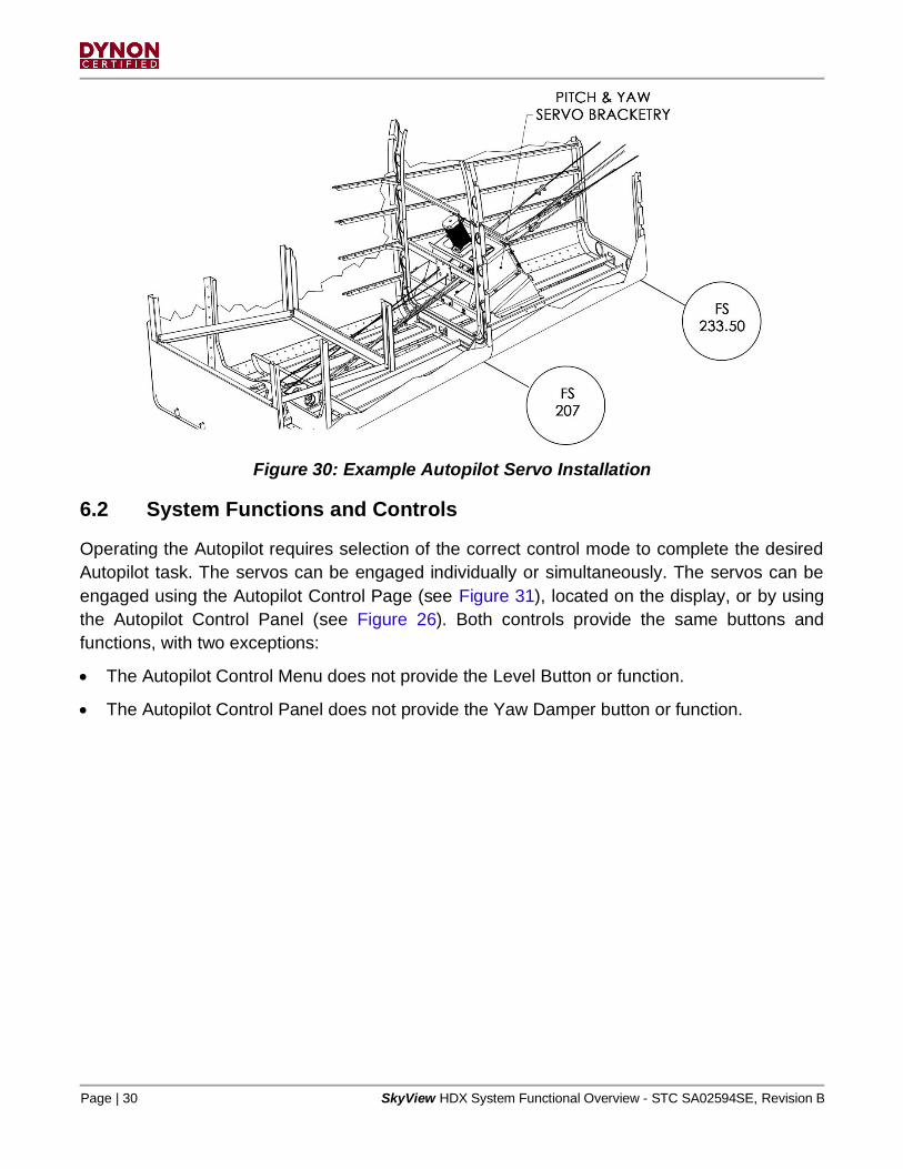
installation. See Figure 29 for a typical Autopilot servo, and Figure 30 for an example of a pitch
and yaw servo installation.
Figure 29: Typical SkyView Servo
Page | 30 SkyView HDX System Functional Overview - STC SA02594SE, Revision B
Figure 30: Example Autopilot Servo Installation
6.2 System Functions and Controls
Operating the Autopilot requires selection of the correct control mode to complete the desired
Autopilot task. The servos can be engaged individually or simultaneously. The servos can be
engaged using the Autopilot Control Page (see Figure 31), located on the display, or by using
the Autopilot Control Panel (see Figure 26). Both controls provide the same buttons and
functions, with two exceptions:
• The Autopilot Control Menu does not provide the Level Button or function.
• The Autopilot Control Panel does not provide the Yaw Damper button or function.

SkyView HDX System Functional Overview - STC SA02594SE, Revision B Page | 31
Figure 31: Autopilot Control Page

Page | 32 SkyView HDX System Functional Overview - STC SA02594SE, Revision B
6.2.1 Autopilot Control Modes
LEVEL Mode: Rolls wings to level and simultaneously returns nose to horizon, then holds
zero vertical speed.
HDG Mode: Turns toward and holds compass heading as selected by HDG/TRK bug.
TRK Mode: Turns toward and holds ground track as selected by HDG/TRK bug.
ROLL Mode: Holds current bank angle, within bank angle limits.
This mode can only be activated when Autopilot is activated and no other
lateral mode (HDG, TRK, or NAV) is selected at time of engagement.
NAV Mode: Follows SkyView’s Flight Plan or third-party connected NAV radio or GPS
guidance.
ALT Mode: Holds the commanded altitude in Autopilot status bar.
When activating this mode, the commanded altitude is automatically set to
the current indicated altitude.
VS Mode: Maintains the selected vertical speed as aircraft performance allows, until
approaching the altitude bug, then transitions to ALT mode.
IAS Mode: Maintains selected airspeed (if not limited by aircraft performance) until
selected altitude approaches, then transitions to ALT to maintain selected
altitude.
VNAV Mode: Intercepts and tracks a glideslope or glidepath.
NOTE: Only the AP and the LEVEL buttons will engage the Autopilot servos.

SkyView HDX System Functional Overview - STC SA02594SE, Revision B Page | 33
7 Communication System
Up to two Communication (COM) Systems can be installed in a SkyView HDX system. When
two COM systems are installed the SkyView HDX system, they are designated COM1 and
COM2. Only one radio can provide frequency data to the Top Bar on the SkyView HDX display.
7.1 System Equipment
The COM System requires installation of the Primary Flight Information System (see Section 3)
or the Engine Monitoring System (see Section 5). In addition to the required equipment for the
major system(s), the following is the minimum equipment required to provide COM functionality:
• At least one – SV-COM-T8 COM transceiver (see Section 7.1.1),
• One per transceiver – SV-COM-PANEL (vertical or horizontal version) COM control
panel (see Section 7.1.1).
7.1.1 SV-COM-X83 COM Radio Kit
The SV-COM-X83 is a TSO VHF COM radio with button-touch and number-dial frequency
tuning. The kit includes one SV-COM-T8 transceiver and one SV-COM-PANEL COM control
panel. The SV-COM-T8 COM transceiver operates at 118.000 MHz to 136.992 MHz with
configurable 8.33 kHz or 25 kHz channel spacing.
Figure 32: SV-COM-PANEL (Horizontal and Vertical Configurations)

Page | 34 SkyView HDX System Functional Overview - STC SA02594SE, Revision B
Figure 33: SV-COM-T8 Transceiver
7.2 System Functions and Controls
The COM System provides two-way voice communications with both air and ground stations
across the aviation frequency spectrum. It communicates with the SkyView HDX system to
receive aviation database information to assist with frequency tuning.
The COM System provides more than just frequency tuning, it can tune frequencies by airport.
By selecting an airport designator on the COM control panel, all frequencies associated with the
airport become selectable by simply pushing the appropriate buttons on the COM RADIO Menu
(see Figure 34) or the COM control panel (see Figure 32). Additionally, the SkyView HDX flight
planning function can "push" an airport to the COM System.
COM info (see Figure 35) is presented on the right side of the Top Bar on the SkyView HDX
display screen. It shows selected Active and Standby frequencies, along with their associated
airport designators. The Active frequency color is Green, and the Standby frequency color is
Cyan.

SkyView HDX System Functional Overview - STC SA02594SE, Revision B Page | 35
Figure 34: COM Control Menu
Figure 35: COM Info in Top Bar

Page | 36 SkyView HDX System Functional Overview - STC SA02594SE, Revision B
8 Transponder System
Up to two SV-XPNDR-261 transponders can be installed in a SkyView HDX system.
8.1 System Equipment
The Transponder System requires installation of the Primary Flight Information System (see
Section 3) or the Engine Monitoring System (see Section 5). In addition to the required
equipment for the major system(s), the following is the minimum equipment required to provide
Transponder functionality:
• One – SV-XPNDR-261 Transponder.
8.1.1 SV-XPNDR-261
The SV-XPNDR-261 transponder (see Figure 36) is a Class 1, Technical Standard Order (TSO),
remote-mounted, Mode-S transponder. It emits/receives TIS Traffic (U.S. only) and is compliant
with FAA 2020 ADS-B Out mandate (14 CFR § / FAR 91.227).
Figure 36: SV-XPNDR-261

SkyView HDX System Functional Overview - STC SA02594SE, Revision B Page | 37
8.2 System Functions and Controls
The Transponder System is controlled using the Transponder Control Menu (see Figure 37).
Transponder status information appears in the Transponder Info Bar located at the top of the
display screen (Figure 38).
Figure 37: Transponder Control Menu
Figure 38: Transponder Information Bar

Page | 38 SkyView HDX System Functional Overview - STC SA02594SE, Revision B
9 IFR Navigation Integration System
The IFR Navigation Integration System allows the SkyView HDX system to interface with TSO
IFR GPS Navigators. The system consists of the remotely-mounted SV-ARINC-429 module.
9.1 System Equipment
For the IFR Navigation Integration System to function effectively, the Primary Flight Information
System (see Section 3) must be installed. In addition to the required equipment for the Primary
Flight Information System, the following is the minimum equipment required to provide IFR
Navigation functionality:
• One – SV-ARINC-429 Converter module,
• One – Third-Party TSO IFR GPS and/or NAV Radio navigators.
9.1.1 SV-ARINC-429 Converter Module
The SV-ARINC-429 converter module converts the ARINC-429 protocol from third-party devices
to the Skyview Network protocol, allowing a SkyView HDX to present IFR GPS Navigator
information.
Figure 39: SV-ARINC-429 Converter Module
9.2 System Functions and Controls
There are no system functions or controls specific to the IFR Navigation Integration System.
Functions and controls are native to the third-party device. When installed, the IFR Navigation
Integration System creates a new tab in the SkyView Flight Plan Page for the third-party device
as a selectable source. Additionally, Flight Plan information from third-party devices can appear
on the Map.

SkyView HDX System Functional Overview - STC SA02594SE, Revision B Page | 39
10 Traffic and Weather Information System
The Traffic and Weather Information System receives ADS-B traffic information via 978 MHz
(UAT) and 1090 MHz and weather information from the FAA’s network of ADS-B ground stations.
With this system installed, a SkyView HDX display can present traffic information on the PFD (if
installed) and traffic and weather on the Map (if installed).
10.1 System Equipment
The Traffic and Weather Information System requires installation of the Primary Flight
Information System (see Section 3). In addition to the required equipment for the Primary Flight
Information System, the following is the minimum equipment required to provide Traffic and
Weather Information functionality:
• One – SV-ADSB-472 module (see Section 10.1.1).
10.1.1 SV-ADSB-472 Module
The SV-ADSB-472 module (Figure 40) is a dual band ADS-B IN receiver. It receives weather
and TIS-B data via 978 MHz UAT (U.S. only) and 1090 MHz ES. In the U.S., it receives free
weather and airspace restriction information (FIS-B) from the FAA’s network of ADS-B ground
stations. FIS-B information is also available if the SV-ADSB-472 is paired with an
SV-XPNDR-261 transponder.
Figure 40: SV-ADSB-472 Module

Page | 40 SkyView HDX System Functional Overview - STC SA02594SE, Revision B
10.2 System Functions and Controls
When Synthetic Vision is enabled, traffic information is presented on the PFD using the
indicators shown in Figure 41. Airport-specific METARs and TAFs are available on the Airport
(APT) page in the INFO Menu.
Figure 41: Traffic Information Displayed on the PFD

SkyView HDX System Functional Overview - STC SA02594SE, Revision B Page | 41
Traffic information is presented on the Map using the same indicators as the PFD, but with
direction arrows to indicate heading and speed, values to indicate altitude, and UP/DOWN
arrows to indicate if the target is climbing or descending as shown in Figure 42. Corresponding
traffic alert annunciations are also generated.
Figure 42: Traffic Information Displayed on the Map

Page | 42 SkyView HDX System Functional Overview - STC SA02594SE, Revision B
Weather information is presented on the Map using colors that indicate precipitation and severity
as shown in Figure 43. Weather controls are in the Weather Options menu (see Figure 44 and
Figure 45).
Figure 43: Weather Information Displayed on the Map

SkyView HDX System Functional Overview - STC SA02594SE, Revision B Page | 43
Figure 44: Menu with Weather Options Control Button
Figure 45: Weather Options Control Menu

Page | 44 SkyView HDX System Functional Overview - STC SA02594SE, Revision B
11 Angle of Attack Indicating System
The Angle of Attack (AoA) system consists of a remotely-mounted AoA sensor on the airplane's
exterior. Because mounting methods vary from aircraft to aircraft, the installation will require the
fabrication or acquisition of an appropriate sensor mount.
11.1 System Equipment
For the AoA System to function, the Primary Flight Information System (see Section 3) must be
installed. The minimum required equipment necessary to provide the AoA function is one AoA
Sensor.
11.2 System Functions and Controls
The system will annunciate a series of audible beeps when the airplane approaches the critical
angle-of-attack (i.e., stall). The beeps will occur faster as the stall angle of attack approaches,
becoming a steady tone at a configured angle at or near the critical angle-of-attack.

SkyView HDX System Functional Overview - STC SA02594SE, Revision B Page | 45
12 Supporting Equipment
The following is a description of SkyView HDX System supporting equipment.
12.1 SV-KNOB-PANEL Knob Control Panel
The SV-KNOB-PANEL control panel (see Figure 46) is installed on an instrument panel. It
provides dedicated knobs to control the ALT, BARO, and HDG/TRK bug functions. The control
panel is available in horizontal and vertical orientations. When an SV-KNOB-PANEL is installed,
the knobs on a SkyView HDX display can still be used set to ALT, BARO, and HDG/TRK. Up to
two Knob Control Panels can be installed in a SkyView HDX System.
Figure 46: SV-KNOB-PANEL (Horizontal & Vertical Versions)
12.2 SV-NET-HUB Network Hub
The SV-NET-HUB network hub (see Figure 47) is an optional accessory that is typically installed
behind an instrument panel near SkyView HDX system components, as well as near Autopilot
servo installations. The SV-NET-HUB simplifies component connection to the SkyView Network.
Figure 47: SV-NET-HUB

Page | 46 SkyView HDX System Functional Overview - STC SA02594SE, Revision B
12.3 Panel Mount USB Port
The Panel Mount USB Port (see Figure 48) is an optional accessory that is typically installed on
an instrument panel. It extends access to the USB ports on a SkyView HDX display. USB ports
are used for transferring files (e.g., firmware updates/backups, database updates, configuration
file uploads/downloads) to a SkyView HDX display.
Figure 48: Panel Mount USB Port

SkyView HDX System Functional Overview - STC SA02594SE, Revision B Page | 47
13 Appendix 1: Glossary
ACO Aircraft Certification Offices (FAA)
ADAHRS Air Data, Attitude and Heading Reference System
ADS-B Automatic Dependent Surveillance Broadcast
AHRS Attitude and Heading Reference System
AEG Airplane Evaluation Group (FAA)
ALT Altitude
AML Approved Model List
AoA Angle of Attack
AP Autopilot
ARINC Aeronautical Radio Incorporated
ATC Air Traffic Control
BARO Barometric Indication
BAT Battery
BIT Built-In Test
CDI Course Deviation Indicator
CFR Code of Federal Regulations
CHT Cylinder Head Temperature
COM Communications
EFIS Electronic Flight Instrument System
EGT Exhaust Gas Temperature
EMS Engine Monitoring System
ES Extended Squitter
FAA Federal Aviation Administration
FAR Federal Aviation Regulations

Page | 48 SkyView HDX System Functional Overview - STC SA02594SE, Revision B
FIS-B Flight Information System - Broadcast
FD Flight Director
GND Ground
GPS Global Positioning System
GNSS Global Navigation Satellite System
HDG Heading
HSI Horizontal Situation Indicator
ICA Instructions for Continued Airworthiness
IFR Instrument Flight Rules
LCD Liquid Crystal Display
LOC Localizer
LRU Line Replaceable Unit
MAG Magnetometer
MFD Multi-functional Display
MHz Mega-Hertz
NAV Navigation
OBS Omni Bearing Selector
OAT Outside Air Temperature
PFD Primary Flight Display
PFI Primary Flight Information
STC Supplemental Type Certificate
TIS Traffic Information System
TIS-B Traffic Information System - Broadcast
TRK Track
TSO Technical Standard Order
VFR Visual Flight Rules

SkyView HDX System Functional Overview - STC SA02594SE, Revision B Page | 49
VHF Very High Frequency
VNAV Vertical Navigation
VOR VHF Omnidirectional Range
VS Vertical Speed
VSI Vertical Speed Indicator
XPDR Transponder