system design guidelines for wide area sensor and/or ...€¦ · system design guidelines for wide...
TRANSCRIPT

Report ITU-R M.2224(11/2011)
System design guidelines for wide area sensor and/or
actuator network (WASN) systems
M Series
Mobile, radiodetermination, amateurand related satellite services
ii Rep. ITU-R M.2224
Foreword
The role of the Radiocommunication Sector is to ensure the rational, equitable, efficient and economical use of the radio-frequency spectrum by all radiocommunication services, including satellite services, and carry out studies without limit of frequency range on the basis of which Recommendations are adopted.
The regulatory and policy functions of the Radiocommunication Sector are performed by World and Regional Radiocommunication Conferences and Radiocommunication Assemblies supported by Study Groups.
Policy on Intellectual Property Right (IPR)
ITU-R policy on IPR is described in the Common Patent Policy for ITU-T/ITU-R/ISO/IEC referenced in Annex 1 of Resolution ITU-R 1. Forms to be used for the submission of patent statements and licensing declarations by patent holders are available from http://www.itu.int/ITU-R/go/patents/en where the Guidelines for Implementation of the Common Patent Policy for ITU-T/ITU-R/ISO/IEC and the ITU-R patent information database can also be found.
Series of ITU-R Reports
(Also available online at http://www.itu.int/publ/R-REP/en)
Series Title
BO Satellite delivery
BR Recording for production, archival and play-out; film for television
BS Broadcasting service (sound)
BT Broadcasting service (television)
F Fixed service
M Mobile, radiodetermination, amateur and related satellite services
P Radiowave propagation
RA Radio astronomy
RS Remote sensing systems
S Fixed-satellite service
SA Space applications and meteorology
SF Frequency sharing and coordination between fixed-satellite and fixed service systems
SM Spectrum management
Note: This ITU-R Report was approved in English by the Study Group under the procedure detailed in Resolution ITU-R 1.
Electronic Publication Geneva, 2011
ITU 2011
All rights reserved. No part of this publication may be reproduced, by any means whatsoever, without written permission of ITU.
Rep. ITU-R M.2224 1
REPORT ITU-R M.2224
System design guidelines for wide area sensor and/or actuator network (WASN) systems
(Question ITU-R 250/5)
(2011)
1 Introduction
There is a growing need to provide wireless access media that can link sensors and actuators associated with humans or widely-dispersed objects to core networks in order to support an increasing number of popular service applications. Mobile wireless access systems are in demand for a variety of services such as environment monitoring, stolen goods tracing, monitoring of gas, water, and electricity use for reducing environmental loads, social security and health care, etc.
The mobile wireless access system is a large cell-based public network that can provide telecommunications to various objects including machine-to-machine services with wide area coverage. A large cell-based wireless access system with a cell radius of about several to ten km is especially practical in supporting rural and non-residential areas as well as urban or residential areas owing to its simple and cost-effective cell deployment.
Research and development activities are making significant progress on mobile wireless access systems, and standardization is now a key issue. From these viewpoints, it is important to share a variety of information. This Report provides detailed information for system design policy, the wireless applications and examples of wide area sensors and/or actuators network (WASN) systems for information sharing.
2 Related ITU-R Recommendations
Recommendation ITU-R P.1406: Propagation effects relating to terrestrial land mobile and broadcasting services in the VHF and UHF bands.
Recommendation ITU-R P.1812: A path-specific propagation prediction method for point to area terrestrial services in the VHF and UHF bands.
Recommendation ITU-R M.1822: Framework for services supported by IMT.
Recommendation ITU-R P.372: Radio noise.
Recommendation ITU-R SM.329: Unwanted emissions in the spurious domain.
Recommendation ITU-R M.2002 (new): Objectives, characteristics and functional requirements of wide-area sensor and/or actuator network (WASN) systems.
Recommendation ITU-R M.1890: Intelligent transport systems (ITS) – Guidelines and objectives.

2 Rep. ITU-R M.2224
3 Abbreviations and acronyms
AS Application server
BB Base band
BPSK Binary phase shift keying
BS Base station
BS-M BS master
BS-R BS remote
DB Database
DROF Digital radio over fibre
EDGE Enhanced data rates for global evolution
GSM Global system for mobile communications
GW Gateway
HSPA High speed packet access
ICT Information and communications technology
IMS IP multimedia subsystem
IP Internet protocol
ITS Intelligent transport system
LDB Location database
LTE Long term evolution
M2M Machine-to-machine
MRC Maximal ratio combining
MTC Machine-type communications
NIMTC Network improvements for MTC
ONU Optical network unit
PLMN Public land mobile networks
PLT Power line telecommunication
QoS Quality of service
QPSK Quadrature phase-shift keying
RF Radio frequency
RN-GW Radio network gateway
RS Relay station
SoC System-on-chip
TDD Time division duplexing
TDMA Time division multiple access
TPC Transmission power control
UMTS Universal mobile telecommunications system
Rep. ITU-R M.2224 3
UNI User-network interface
UT User terminal
WASN Wide area sensors and/or actuators network
WN-GW Wired network gateway
WT Wireless terminal
WT-MS WT management server.
4 Service applications
The wireless system can support a variety of services on its common platform. Available service categories and service examples are shown below. Detailed service examples are shown in Section 7.
– Automation and efficiency enhancement of business works:
i) remote meter reading of utilities such as water, gas and electricity;
ii) asset management;
iii) maintenance information management.
– Meteorological observation:
i) air temperature and humidity measurement;
ii) precipitation measurement;
iii) water level measurements of rivers and the sea;
iv) CO2 concentration measurement.
– Environment observation, forecasting, and protection:
i) environmental pollution observation, including air, water and soil;
ii) industrial waste investigation;
iii) monitoring in the chemical industry;
iv) ecosystem investigation.
– Crime prevention and security:
i) intrusion detection;
ii) robbery alert;
iii) location management of articles of value;
iv) location management of the elderly and children.
– Healthcare, medical applications and welfare support:
i) monitoring of vital parameters (e.g. body temperature, weight and heart rate) measurement and management;
ii) position and posture monitoring, assistance to the elderly and chronic patients.
– Remote control and monitoring of plant facilities:
i) remote control of manufacturing process;
ii) abnormality monitoring.
– Disaster prevention and measures:
i) earthquake observation (e.g. seismic sensing);
ii) flood monitoring;

4 Rep. ITU-R M.2224
iii) debris flow observation.
– Smart homes and control of commercial building:
i) appliance networking;
ii) remote built-in software update;
iii) gate control system and visible talking.
– Intelligent transportation and traffic management systems1:
i) informed parking management;
ii) advanced travellers’ information;
iii) traffic investigation;
iv) road pricing.
– Other service examples:
i) goods distribution, such as mobility management of trucks and baggage;
ii) monitoring of avian species that may carry the avian influenza virus;
iii) personal security, such as child tracking and intruder detection.
5 Network architecture
5.1 Network functionalities
To provide the services described in Section 4, the fundamental network functionalities of the WASN systems are shown below:
– Automatic sensing information collection: This application automatically collects the information acquired by sensors and sends it to application servers (ASs) or databases (DBs) via the core network to which the wireless access system is connected.
– Remote actuator control: This application lets the users control actuators remotely via ASs via the core network. The control information for the actuators is transferred from the ASs to the actuators via the wireless access system.
5.2 Network configuration
A network configuration for achieving the network functions described in Section 5.1 is shown in Fig. 1. The wireless network in this document can be connected to a core network such as the public IP (Internet protocol) network via a radio network gateway (RN-GW). User terminals (UTs) such as sensors and/or actuators can be connected to the network via wireless terminals (WTs). Moreover, ASs and DBs can be connected to the network via a wired network gateway (WN-GW).
1 Guidelines and objectives of Intelligent transport systems (ITS) are described in Recommendation ITU-R M.1890.

Rep. ITU-R M.2224 5
FIGURE 1
Network configuration
5.3 Wireless network
In principle, WTs can communicate with the BS directly. It enables simple system implementation. Although a relay station (RS) that compensates for dead spots can be also installed, the simpler single-hop approach is rather preferable to reduce installation costs, complexity of control mechanisms, and additional power consumption.
5.4 Network equipment
The network equipment comprises the BSs, RSs, WTs, an RN-GW, a WN-GW and a wireless terminal management server (WT-MS).
5.4.1 Base station (BS)
Each BS can be connected to the core network via the RN-GW. It can receive information from the WTs and send it to the RN-GW. On the other hand, it sends control information received from the RN-GW to the specific UT intended to be controlled as an actuator. The BS can have functions for communicating with the WTs, encryption and decryption, and communicating with the RN-GW.
5.4.2 Wireless terminal (WT)
The WT can be connected to a UT, which is explained in Section 5.5.1, acting as a sensor and/or actuator. When the UT is acting as a sensor, the WT can receive sensing information from it. When the UT is acting as an actuator, the WT sends control information to it. The WT can connect to the BS via a wireless link. It can have functions for communicating with the UT, communicating with the BS, encryption and decryption, and authentication.
Core Network WN-GW AS and/or DB
UNIBS
WT-MS
WT
UNI
UT
Wireless network
AS and/or DB
RS
WT
UNI
UT
BS
RN-GWRN-GW Core Network WN-GW AS
and/or DB
UNIBS
WT-MS
WT
UNI
UT
Wireless network
AS and/or DB
RS
WT
UNI
UT
BS
RN-GWRN-GW

6 Rep. ITU-R M.2224
5.4.3 Radio network gateway (RN-GW)
The RN-GW can accommodate multiple BSs. It can send sensing information from the BS to the core network. On the other hand, it can send control information received from the AS to the BS accommodating the WT that is connected to the target actuator.
5.4.4 Wired network gateway (WN-GW)
The WN-GW can accommodate multiple ASs and/or DBs. It can send control information from the ASs to the core network. On the other hand, it can send sensing information from sensors to the AS or DB intended to collect its information.
5.4.5 WT management server (WT-MS)
The WT-MS can have a database and a function for managing WT location and management information such as authentication information and ID.
5.5 Network access equipment
The UTs and ASs and/or DBs can be used as equipment for accessing the network. The UT can be connected to the network via the WT. The ASs and/or DBs can be connected to the network via the WN-GW.
5.5.1 User terminal (UT)
The UT can function as a sensor and/or actuator. It can communicate with the WT.
5.5.2 Application server (AS) and database (DB)
The ASs and DBs can have functions for collecting sensing information, processing it, and storing it in a database. In addition, the AS can have a function for controlling an actuator.
6 System design guidelines
This section describes specific aspects of system design guidelines for WASN, considering the objectives, characteristics, and functional requirements noted in draft new Recommendation ITU-R M.2002
6.1 Radio frequency
Since covering large areas with low density of WTs is one of the system objectives according to draft new Recommendation ITU-R M.2002 a large-cell radius system design could be used.
To achieve this goal, propagation characteristics such as:
– small distance attenuation (small transmission power loss against distance);
– high diffraction for non-line-of sight communication,
should be satisfied within the applied radio-frequency bands, which also benefits the dense urban case. In addition, man-made noise should be also considered.
Propagation characteristics
The services need to be supported under non-line-of-sight propagation environments for indoor/outdoor communications. For reference, propagation effects in the VHF and UHF bands are provided in Recommendation ITU-R P.1406, and a path-specific propagation prediction method is described in Recommendation ITU-R P.1812.

Rep. ITU-R M.2224 7
Man-made noise
The fact that reception sensitivity is affected by man-made noise radiated from home appliances and other ICT devices must be considered. For reference, Recommendation ITU-R P.372 provides information in the frequency range from 0.1 Hz to 100 GHz.
In urban areas, in order to avoid high levels of man-made noise, it is preferable to use relatively higher frequencies, since levels of man-made noise tend to be higher at lower frequencies. Conversely, in areas where the noise does not cause serious problem, e.g. rural areas, it is preferable to use lower frequencies to reduce the propagation loss.
Thus, the higher portion of VHF or the lower portion of UHF is suitable for the system.
6.2 Radio link design for asymmetrical system
Practical accommodation of quite a large number of sensors and/or actuators with limited power supply is one of the system objectives according to the new Recommendation ITU-R M.2002 Thus, it is preferable the WT constraints below be considered:
– simple implementation;
– simple signal processing;
– low power consumption and long working time for battery powered WT.
The system is extremely asymmetrical in which a powerful BS can compensate for the communication quality deterioration caused by the above WT constraints.
Because there are a lot of implementation constraints with WTs, and there are many more WTs than BSs, it is preferable that the radio-link design should consider improvement of reception sensitivity, increase in BS transmission power, and application of diversity techniques under these WT constraints.
6.2.1 Reception sensitivity
To achieve large-cell implementation, improvement in reception sensitivity is essential. The reception sensitivity can be improved by two approaches: narrowing the signal bandwidth or improving the noise figure of radio-frequency devices. Both are effective in uplink connections in reducing the burden of WTs (e.g. transmission power or applicable RF devices).
6.2.2 Transmission power
It is preferable that BS transmission power be decided considering the WT reception sensitivity deterioration, characteristics of power amplifier and antennas, in-house man-made noise in the used bands, licence-exempt use of WTs, and so on.
6.2.3 Diversity techniques
It is preferable to apply diversity techniques that can avoid the transmission quality deterioration caused by fading and shadowing, in order to cover a wide area and provide stable communication.
6.2.3.1 Fading countermeasures
To avoid the transmission quality deterioration caused by fading, space diversity techniques that install two or more antennas at each BS site are effective. Furthermore, space diversity techniques that can be achieved with a single antenna on the WT side are preferable from the viewpoint of practical implementation of WTs. For this purpose, reception diversity techniques such as maximal ratio signal combining (MRC) or antenna selection can be applied in the uplink. Conversely, transmission diversity techniques such as frequency offset or space-time coding can be applied in the downlink.

8 Rep. ITU-R M.2224
6.2.3.2 Shadowing countermeasures
To avoid the transmission quality deterioration caused by shadowing, which is triggered by obstacles in the propagation path like buildings, site diversity (or path diversity) techniques that provide two or more BS-WT propagation paths are useful. Likewise it is also preferable that site diversity techniques provide reception diversity in the uplink and transmission diversity in the downlink from the viewpoint of practical WT implementation.
6.3 Co-channel interference countermeasures
The standby output power radiated from different WTs within the same cell becomes co-channel interference at a BS. Since the system aims to accommodate quite a lot more WTs than existing cellular systems, it is preferable to minimize the standby output power for each WT be decided based on the density of WTs in the cell.
6.4 Coexistence with other systems
The system should consider the coexistence issues with existing wireless systems in the frequency band of operation. Spurious emissions and spurious response requirements should be decided in line with this consideration. Requirements for spurious emission limit should be applied based on Recommendation ITU-R SM.329. Potentially some coexistence issues could be addressed with resource sharing.
6.5 QoS
To offer QoS for WASN services, it is preferable to create criteria that assure the provision of the required QoS.
6.6 Security
To offer secured WASN services, it is preferable to create a certain policy that can assure the provision of WASN security comparable to the public network when required.
7 Wireless system applications
The wireless systems that have the above characteristics should support the service applications.
Potential example systems are as follows:
– VHF-band WASN system;
– GSM/EDGE/UMTS/HSPA/LTE mobile systems for WASN;
– IEEE WirelessMAN-OFDMA and WirelessMAN-Advanced mobile systems for WASN;
– IMT systems used to support WASN applications.
For information sharing, detailed information is provided in the following subsections.
7.1 VHF-band WASN system
7.1.1 Overview
A VHF-band WASN system has been proposed as a network that can provide economical sensor and/or actuator network service in Japan. The wireless access system for the VHF-band WASN system is a large cell-based public wireless access system in which WTs have long battery lifetimes and the BSs directly accommodate WTs within a service area radius of several kilometres.
Rep. ITU-R M.2224 9
The VHF-band WASN system may be used for the following applications for habitable areas (urban/suburban areas): 1) remote meter reading for public utilities such as electricity, gas, and water and 2) meter control for remote maintenance or emergency shut-off.
7.1.2 System features
In general, the meter-reading system installed by a public utility takes 5 to 10 years to upgrade, including meter replacement. The upgraded system may be used for 30 years or so. Thus, the target wireless system must be a platform that can provide meter-reading applications for a long time, namely, several decades.
To accommodate utility meters, the VHF-band WASN system is basically designed as a cell-based system that supports densities of up to 500 WTs / km2 considering typical habitable areas. The following parameters were set:
– battery lifetime: around 10 years;
– cell size (transmission distance): 3.5 km;
– number of wireless terminals accommodated in a cell: around 20 000;
– transmission rate: 9 600 bps.
Although this basic design targeted typical habitable areas, the system must consider more complicated situations such as covering metropolitan areas where the density of utility meters is extremely high and increased propagation link margins are needed. In order to meet the WT density requirement, decreasing cell size or increasing the number of frequency channels can be adopted. Furthermore, enhanced options considered to increase the link margin.
7.1.2.1 Battery lifetime
Meters are calibrated about every 10 years, so the batteries for the wireless terminals connected to the meters should last at least 10 years and be replaced at the time of calibration.
7.1.2.2 Cell size
The system incorporates base station antennas on the rooftops of telephone exchanges, which can be easily implemented by telephone operators. Considering the density of existing exchanges, a cell radius of about 3.5 km is adopted for the basic design of the system. For metropolitan areas, a smaller cell radius, 1.5-3.5 km, is adopted, since the density of utility meters may be very high.
7.1.2.3 Number of WTs to be accommodated
WT densities of up to 500 WTs / km2 is adopted for the basic design considering typical habitable areas (50-1 000 persons / km2), since there may be about at least two persons per household on average. System capacity can be defined by the number of WTs that a BS can accommodate. Since the cell radius of the basic design is 3.5 km, the number of WTs to be accommodated becomes
500 (WTs / km2) × 3.5 (km) × 3.5 (km) × 3.14 = 20 000 (WTs / cell).
Then, the basic design of the system is expected to accommodate about 20 000WTs in each cell. In metropolitan areas, the number of WTs accommodated per cell may be ten times that of the basic design.
7.1.2.4 Transmission rate
The required bandwidth can be calculated from the number of WTs accommodated, data volume per WT per day, and wireless access efficiency. Here:
required bandwidth = 20 000 × 1 [kbyte/day] ÷ 0.2 ≒ 9 480 bps
10 Rep. ITU-R M.2224
where:
number of WTs accommodated: 20 000;
data volume per WT per day: 1 kbyte; and
wireless access efficiency: 0.2.
Note that the wireless efficiency is determined considering both media access control efficiency (0.3), and the overhead of the upper layers. Thus, the transmission rate of 9 600 bps is reasonable if each cell is covered by one frequency channel. In metropolitan areas, man-made noise from electronic devices is very large, and propagation conditions are severe. Thus, the enhanced options of lower transmission rates are provided to achieve adequate link margins (see also 7.1.2.5).
7.1.2.5 Propagation path characteristics
Because utility meters are attached to the walls of houses, propagation paths are usually non-line-of-sight. Therefore, a typical suburban model based on the Okumura-Hata equation can be applied to typical residential areas. In metropolitan areas, a considerable number of tall buildings and condominiums whose utility meters are enclosed in some form of steel box (pipe-shafts) exist. Thus the propagation conditions are very severe. Therefore, the enhanced options that enable raising the transmission power of BS and WTs or lowering the transmission rate contribute to some increase of the link margin.
Design details regarding other parameters are given in the characteristics in Section 6.
7.1.3 Network configuration
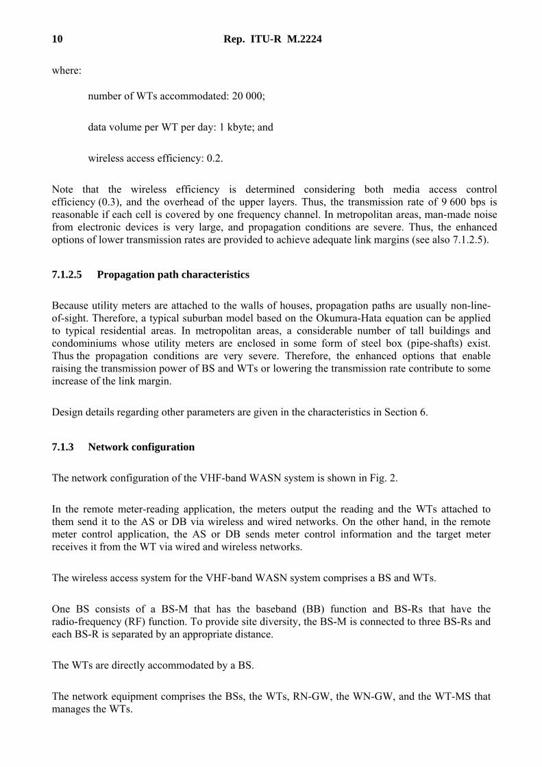
The network configuration of the VHF-band WASN system is shown in Fig. 2.
In the remote meter-reading application, the meters output the reading and the WTs attached to them send it to the AS or DB via wireless and wired networks. On the other hand, in the remote meter control application, the AS or DB sends meter control information and the target meter receives it from the WT via wired and wireless networks.
The wireless access system for the VHF-band WASN system comprises a BS and WTs.
One BS consists of a BS-M that has the baseband (BB) function and BS-Rs that have the radio-frequency (RF) function. To provide site diversity, the BS-M is connected to three BS-Rs and each BS-R is separated by an appropriate distance.
The WTs are directly accommodated by a BS.
The network equipment comprises the BSs, the WTs, RN-GW, the WN-GW, and the WT-MS that manages the WTs.
Rep. ITU-R M.2224 11
FIGURE 2
Network configuration of VHF-band WASN system
7.1.4 System characteristics
This section describes the system characteristics of the wireless access system for the VHF-band WASN system. To clarify the system’s feasibility, devices have actually been implemented and field experiments have been conducted. The feasibility study of the wireless system is described in Appendix 1 from the viewpoint of communication range.
7.1.4.1 System parameters
An experimental system according to the basic design was developed to conduct feasibility studies on wide-area mobile sensor networks (See Appendix 1). The system is designed as a cell-based system to suit covering habitable areas with relatively little man-made noise. The main parameters and/or methods are summarized in Table 1, follow the technical specifications of VHF-band WASN system being developed by Multimedia Mobile Access Communication Systems (MMAC) Forum, Japan (http://www.arib.or.jp/mmac/report/e/2011/mmac-2011-0001(WASN).pdf ). The enhanced options extend the parameters such as modulation rate or transmission power in order to increase link margins and so counter the large man-made noise and severe propagation conditions in metropolitan areas. By applying a lower modulation rate or higher transmission power, outage probability of the connection can be reduced.
12 Rep. ITU-R M.2224
TABLE 1
Main system parameters of VHF-band WASN system
Parameters Values Notes
Frequency band Higher portion of VHF bands
280 MHz was licensed in Japan for experimental purposes only.
Modulation rate Downlink: 9 600 baud Uplink: 9 600 baud
Modulation rate of 9 600 baud is considered the basic design of the system.
(option) Uplink: 4 800, 2 400, 1 200, 600 baud
The uplink modulation rate is switched from 9 600 to 4 800, 2 400, 1 200 and 600 baud in order to increase link margins in metropolitan areas.
Transmission power WT: 10 dBm BS: up to 36 dBm
The transmission power of WTs is defined as 10 dBm, assuming a low-power data communication system. BS transmission power is set to up to 36 dBm considering the man-made noise at WTs or the link margins in downlink.
(option) WT: up to 30 dBm The transmission power of WTs can be increased to increase link margins in metropolitan areas. The transmission power of WTs and BS can be adjusted for radio link design according to supported area or applications.
Multiple access method TDMA To accommodate a large number of WTs, TDMA is applied as the multiple access method. TDMA allows BS to flexibly control or assign bandwidth via a centralized control.
Duplexing method TDD TDD is applied as the duplexing method because two-way single-band transmission and open-loop transmission power control are available.
Modulation method Downlink: π/2-shift BPSK (signal) π/4-shift QPSK (data) Uplink: π/4-shift QPSK
For control signal transmission in downlink, π/2-shift BPSK is applied for robust operation of the system. For data transmission, π/4-shift QPSK is applied as the modulation method due to its spectral efficiency.
(option) Downlink: 16QAM (data)
In addition to the parameters of the basic type, 16QAM is defined as an option for network management by multi-cast signal control in downlink.
Detection method Downlink: Differential detection Uplink: Coherent detection
On the WT side, differential detection is applied as a signal detection method, where frequency offset diversity can be applied. On the BS side, coherent detection is applied.
Forward error correction and interleaving
Convolutional coding and Viterbi decoding
To avoid transmission quality deterioration caused by fading and to improve the communication range, forward error correction is applied using convolutional coding and Viterbi decoding. In addition, bit interleaving on the temporal axis is applied to avoid burst errors caused by fading.

Rep. ITU-R M.2224 13
TABLE 1 (end)
Main system parameters of VHF-band WASN system
Transmission power control (TPC)
Open-loop TPC In uplink transmission, a simple open-loop TPC is applied to ensure a large reception dynamic range and to avoid the distance problem of the WTs in adjacent frequency channels.
Diversity method Space and site diversity Uplink: MRC Downlink: frequency offset
The system assumes that each WT has a single antenna and that an BS has multiple antennas. Thus, the diversity techniques of a multi-to-single antenna configuration in the downlink and a single-to-multi antenna one in the uplink are applied. In addition, space and site diversity techniques are combined to improve the diversity effect.
7.1.4.2 Cell configuration
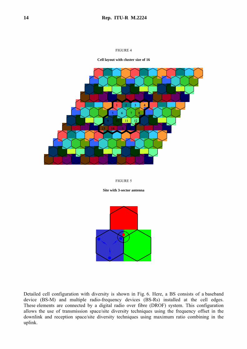
The cell layout with cluster size of 7 (frequency channels) is shown in Fig. 3, and one with 16-cell repetition is also shown in Fig. 4. This latter layout can well suppress co-channel interference from neighbouring cells by separating cells sharing the same frequency channel, although it requires more frequency bandwidth. Thus, outage probability of the connection can be reduced by applying the latter layout. It is noted that the cell repetition numbers mentioned are just configuration examples and actual number is not limited to those specific parameters. Antenna deployment at each site (dotted circle) with a three-sector configuration is shown in Fig. 5, where BS antennas are located at the vertex of each hexagon cell. This configuration enables each site to form three sectors.
FIGURE 3
Cell layout with cluster size of 7
1
32
5
4 7
6
14 Rep. ITU-R M.2224
FIGURE 4
Cell layout with cluster size of 16
FIGURE 5
Site with 3-sector antenna
Detailed cell configuration with diversity is shown in Fig. 6. Here, a BS consists of a baseband device (BS-M) and multiple radio-frequency devices (BS-Rs) installed at the cell edges. These elements are connected by a digital radio over fibre (DROF) system. This configuration allows the use of transmission space/site diversity techniques using the frequency offset in the downlink and reception space/site diversity techniques using maximum ratio combining in the uplink.
1 2 43
8765
1211109
16151413
1 2 43
8765
1211109
16151413
1 2 43
8765
1211109
16151413

Rep. ITU-R M.2224 15
FIGURE 6
Cell configuration with space and site diversity
7.1.4.3 Wireless terminal features
To meet the features of wireless terminal described in the new Recommendation ITU-R M.2002, various approaches can be used. For example, SoC permits a wireless circuit and baseband circuit to be implemented on one chip, which enables each device to have low power consumption. WTs are also provided with intermittent transmission and reception behaviour, which also reduces the power consumption. In addition, WTs are implemented with a dielectric oscillator with a frequency stability of around 2 × 10⁻⁵, which enables low-cost implementation.
7.1.5 Available service examples
The wireless system can provide three kinds of applications as follows.
7.1.5.1 Remote collection application of sensing information
This application offers a communication service in which the information gathered by the sensors is collected to the user terminal connected to a VHF-band WASN system in Japan via the wireless network. As application examples, a remote gas-meter reading, visualization service of home energy consumption and a remote monitoring for agriculture are shown below.
Remote gas-meter reading
This application allows the gas company to automatically collect sensing and alarm information from the WTs connected to each gas meter.
Space diversitySite diversity
Space diversity
Space diversitySite diversity
Space diversity
BS-R
BS-R
BS-R
DROF
BS-M

16 Rep. ITU-R M.2224
FIGURE 7
Remote gas-meter reading
Visualization of home energy consumption
This application allows home owners to visualize the energy consumption of each home for environmental assessment or saving money. The field experiment results related to this application are shown in Appendix 2.
FIGURE 8
Visualization of home energy consumption
Remote monitoring for agriculture
This application allows farm companies to automatically collect soil and atmosphere information via the WTs connected to environmental sensors in order to monitor the growth of crops remotely.
WASN
Gas company
AS or DB
AS: application serverDB: database
WASN
Gas company
AS or DB
AS: application serverDB: database
WASN
AS or DB
Electricity
Water
Gas
InternetInternet
meter
meter
meter
customer
AS: application serverDB: database
WASN
AS or DB
Electricity
Water
Gas
InternetInternet
meter
meter
meter
customer
AS: application serverDB: database

Rep. ITU-R M.2224 17
FIGURE 9
Remote monitoring for agriculture
7.1.5.2 Remote actuator control application
This application lets the users or the operators control actuators remotely from a control centre. An application example is shown below.
Remote diagnosis and maintenance of networks
This application allows control operators to find troubles or irregular situations over the network, and allows operators to control home/office network appliances remotely.
FIGURE 10
Remote diagnosis and maintenance of networks
Remote control of office air conditioning
This application allows control operators to collect environmental information such as temperature and humidity throughout office rooms or the whole building, and helps optimize energy use by controlling distributed air conditioners. The field experiment results related to this application are shown in Appendix 2.
AS or DB
Remote monitoring
Remote consulting
WASN
WASN
WASNAS: application server DB: database
AS or DB
Remote monitoring
Remote consulting
WASN
WASN
WASNAS: application server DB: database

18 Rep. ITU-R M.2224
FIGURE 11
Remote control of office air conditioning
7.1.5.3 Network information providing application
This application gives to the users network access information and WT location information generated by the AS and DB. As an application example, the remote location management of objects and humans with WTs is shown below.
Remote location management
FIGURE 12
Remote location management
7.2 GSM/EDGE/UMTS/HSPA/LTE mobile systems for WASN
The availability of such technologies with a so high number of modules and terminals has also concurred to provide the cost benefits related to very large scale production.
As a consequence of deployment of GSM/EDGE/UMTS/HSPA/LTE packet data systems supporting a large number of terminals, there is a foundation for support of WASN. Today a significant number of sensors and actuators are already using mobile networks as WASN. Typical applications are including cases where mobility is strictly required (e.g. fleet management,
WASN
Control centre
Air conditioner Air conditioner
Air conditionerAir conditioner
Temperature / humidity sensor grids
InternetInternet AS or DB
Office room
Control
Temperature/humidity
AS: application server DB: database
WASN
Control centre
Air conditioner Air conditioner
Air conditionerAir conditioner
Temperature / humidity sensor grids
InternetInternet AS or DB
Office room
Control
Temperature/humidity
AS: application server DB: database
LDB
× × ×
Location check
WASN
N/AN/A N/A
LDB: location database
LDB
× × ×
Location check
WASN
N/AN/A N/A
LDB: location database

Rep. ITU-R M.2224 19
logistics, connected consumers, etc.), cases where alternative connectivity means are difficult (sensors/ actuators in remote areas), as well as cases where the use of the mobile technologies simplify management, installation and configuration without necessarily implying mobility support. The two typical configurations are shown in Fig. 13:
FIGURE 13
Two typical configurations
The first one refers to the case where the sensor/actuator is directly supported by a GSM/EDGE/UMTS/HSPA/LTE Mobile Terminal (typical situation when power sources are available and the amount of data to be transmitted is potentially relevant, e.g. several automotive applications).
The second one refers to a gateway (GW) using GSM/EDGE/UMTS/HSPA/LTE technology for long range communication, while the sensors/actuators are connected through a short/medium range wireless technology, often supporting very low battery consumption, e.g. IEEE 802.15.4. Also the case of a wired technology between the sensors/actuators and the GSM/EDGE/UMTS/HSPA/LTE gateway applies, as currently done today with power line telecommunication (PLT) systems in power supply metering. The gateway acts a concentrator, allowing a more efficient use of the GSM/EDGE/UMTS/HSPA/LTE spectrum and mobile network resources.
These scenarios are also supported by emerging standards related to the machine to machine, including the activities explicitly dedicated to the M2M system (e.g. ETSI TC M2M) and the one related to the wireless sensors technology (e.g. IEEE 802.15.4).
20 Rep. ITU-R M.2224
Additionally 3GPP is developing in Release 10 and Release 11 the standardization for system improvement for machine type communications, with the aim to further support the massive development of such type of devices/gateway. The objective of this work item is to study additional requirements, use cases and functionality beyond those specified by the Release 10 network improvements for machine-type communications (NIMTC) work item on the following aspects:
– network improvements for MTC device to MTC device communications via one or more public land mobile networks (PLMNs). Note: direct-mode communication between devices is out of scope;
– possible improvements for MTC devices that act as a gateway for 'capillary networks' of other devices. Note: capillary networks themselves are out of scope of 3GPP;
– network improvements for groups of MTC devices that are co-located with other MTC devices;
– improvements on network selection mechanisms and steering of roaming for MTC devices;
– possible enhancements to IP multimedia subsystem (IMS) to support MTC;
– possible improvements for location tracking of MTC devices;
– service requirements on communications between PLMN and the MTC user/MTC server (e.g. how the MTC user can set event to be monitored with MTC monitoring);
– possible service requirements to optimize MTC devices;
– possible new MTC features to further improve the network for MTC.
Specifications developed in support of MTC include:
3GPP TS 22.868, “Study on facilitating machine to machine communication in 3GPP systems”.
3GPP TR 33.812, “Feasibility study on remote management of USIM application on M2M equipment”.
3GPP TS 22.368, “Service requirements for Machine-Type Communications (MTC); Stage 1”.
3GPP TR 23.888, “Architectural Enhancements for machine-type communications”.
3GPP TR 37.868, “RAN Improvements for Machine-type Communications”.
3GPP TR 43.868 “GERAN Improvements for Machine-type Communications”.
The 3GPP GSM/EDGE/UMTS/HSPA/LTE systems are described and specified in a wide set of specification and are referenced in the following specifications (available at http://www.3gpp.org/ftp/Specs/archive/).

Rep. ITU-R M.2224 21
3GPP TS 41.101 Technical Specifications and Technical Reports for a GERAN-based 3GPP system.
3GPP TS 21.101 Technical Specifications and Technical Reports for a UTRAN-based 3GPP system.
3GPP TS 21.201 Technical Specifications and Technical Reports for an Evolved Packet System (EPS) based 3GPP system.
3GPP TS 21.202 Technical Specifications and Technical Reports relating to the Common IP Multimedia Subsystem (IMS).
7.3 IEEE WirelessMAN-OFDMA and WirelessMAN-Advanced mobile systems for WASN IMT systems used to support WASN applications
As stated throughout this document, WASN aims to bring communication technologies and services to the market in a large scale with minimal operational and capital expense. The IEEE 802.16 mobile system is able to serve as a technical ground for providing both management of a WASN network and WASN service specific technologies enabling. The objective of the IEEE P802.16p project is to enable a range of WASN applications that are automated rather than human-controlled and which require Wireless Metropolitan Area Network (WMAN) communication in licensed bands. These applications have network access requirements that may be significantly different from those used to support standard cellular connections. Some of the WASN applications of interest include secured access and surveillance, tracking, tracing and recovery, public safety, vehicular telematics, healthcare monitoring of biosensors, remote maintenance and control, smart metering, automated services on consumer devices, and retail digital signage.
IEEE P802.16p specifies enhancements to the IEEE 802.16 medium access control (MAC) layer and minimal modifications to the IEEE 802.16 WirelessMAN-OFDMA and WirelessMAN-Advanced physical layers (PHY), which are based on orthogonal frequency division multiple access (OFDMA).
FIGURE 14
M2M service system architecture
As shown in Fig. 14, data to be collected by the M2M server may be gathered directly by the IEEE 802.16 M2M devices or by non-IEEE 802.16 M2M devices, which then IEEE 802.16 M2M devices will forward to the M2M server. The Access Service Network (ASN) manages its subordinate

22 Rep. ITU-R M.2224
M2M devices according to results of communication with the M2M server. The Connectivity Service Network (CSN) stores collected data from M2M devices for access by M2M client applications.
The IEEE 802.16 Working Group (WG) is developing a project IEEE P802.16p, with expectation to improve the system specifically for WASN networks, while retaining compatibility with the previously-specified IEEE 802.16 mobile networks. The M2M Task Group of the IEEE 802.16 WG has specified system design criteria and functional requirements, including applicable use case scenarios, as delineated in the “Machine to Machine (M2M) Communications Technical Report (IEEE 802.16p-10/0005)”. To meet the requirements, the following considerations are taken into account in the IEEE P802.16p project:
1) Provision of reliable network accessibility for large number of M2M devices.
2) Improvement on low power consumption for fixed/nomadic/mobile/grouped M2M devices.
3) Provision of group management operation for large number of M2M devices.
4) Support efficient resource scheduling depending on type of task (e.g., predictable task, time tolerant task etc.) of M2M device.
5) Possible service requirements to optimize M2M Devices depending on traffic type of WASN application.
6) Support of M2M specific traffic patterns (e.g., small/large data bursts).
7) Improvement on security provision between the BS and individual or groups of M2M devices.
Technical descriptions may be found in the following specifications. The system requirements of IEEE P802.16p can be found in the System Requirements Document (SRD), which is still under development.
IEEE Std 802.16-2009 IEEE Standard for Local and Metropolitan Area Networks – Part 16: Air Interface for Broadband Wireless Access Systems.
IEEE Std 802.16m-2011 Amendment to IEEE Standard for Local and Metropolitan Area Networks – Part 16: Air Interface for Broadband Wireless Access Systems – Advanced Air Interface.
IEEE 802.16p-10/0004r2 IEEE 802.16p Machine to Machine (M2M) System Requirements Document (SRD).
7.4 IMT systems used to support WASN applications
WASN application can be supported by IMT (see for example Recommendation ITU-R M.1822 “Framework for services supported by IMT”). In particular, for IMT-2000 multiple QoS classes are defined in Recommendation ITU-R M.1079. It defines four QoS usage classes: conversational, interactive, streaming and background classes of service. For delivery-time-sensitive services like remote control of plant facilities or intruder detection, at least one time-sensitive QoS class like interactive or streaming should be defined and supported. For delivery-time-insensitive M2M services the use of a delay-tolerant QoS class like the background class might be dominant.

Rep. ITU-R M.2224 23
APPENDIX 1
Feasibility study on an example experimental system through field experiments
1 Scope
This Appendix provides results of field experiments on a mobile sensor and actuator network, accompanied with restricted power emission from wireless terminals over wireless links of several km [1]. These results suggest the feasibility of a cell-based wireless system that satisfies the characteristics and the concept of connecting a large number of sensors and/or actuators over wide areas to efficiently support public communication services.
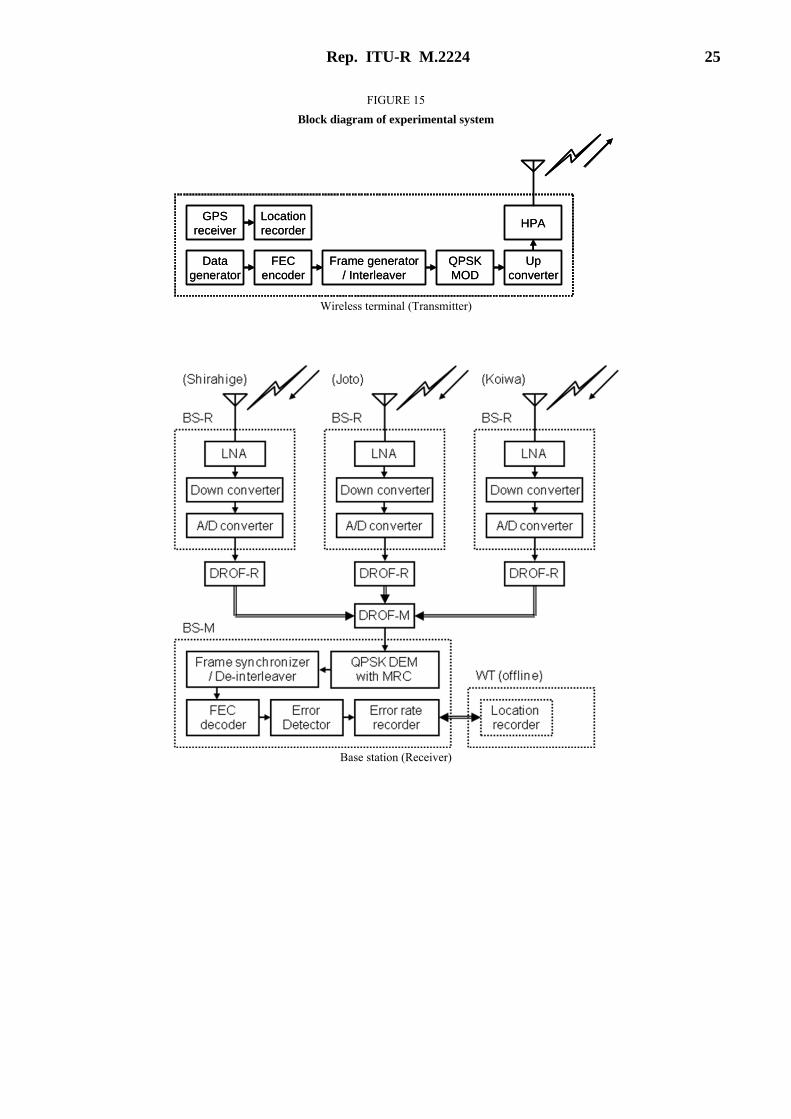
2 Outline of field experiments
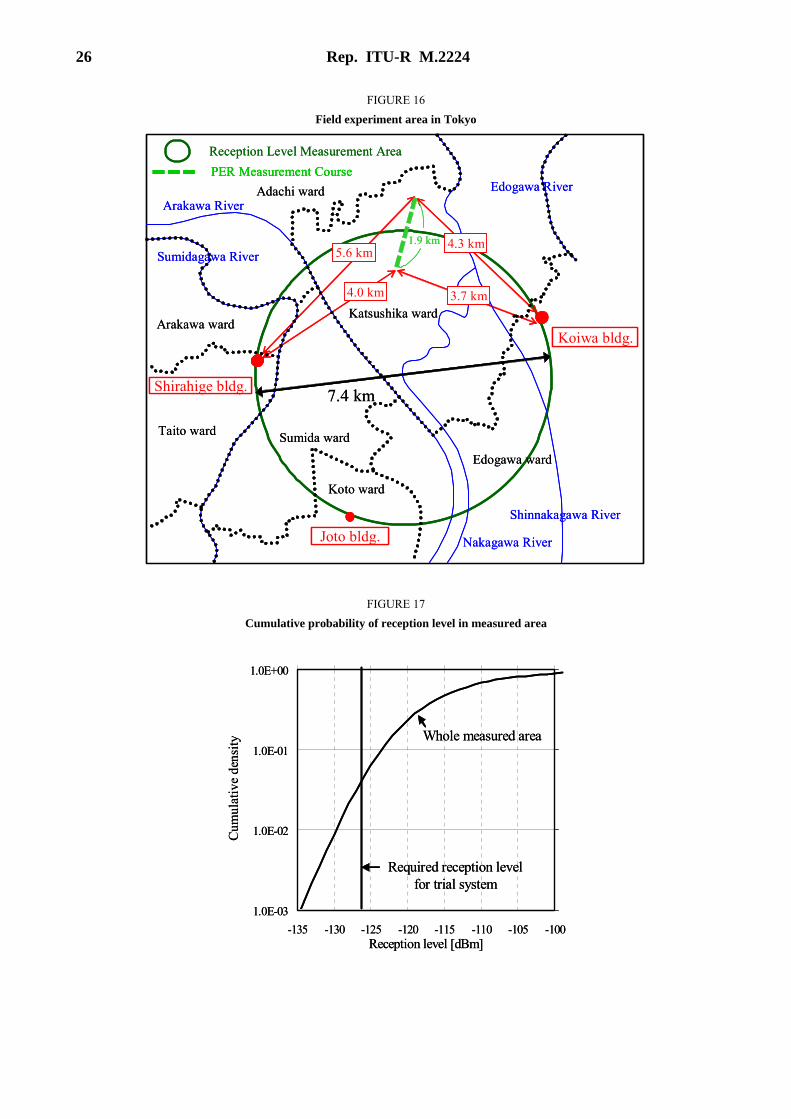
In Japan, an experimental system has been developed to conduct feasibility studies of wide-area mobile sensor networks with wireless communications. The major system parameters are shown in Table 1. A block diagram of the experimental system is shown in Fig. 15. We conducted field experiments in Tokyo, cell radius of around 4 km, to confirm the technical feasibility of wide-area coverage. The area of the field experiments is shown in Fig. 16. In the field test, three BS-Rs and one BS-M were used to evaluate two attributes of the uplink performance of 3-site diversity without space diversity; the reception level, and PER performance. Three antennas were connected to an AP-M via DROF, and were placed on the rooftops of Shirahige, Joto and Koiwa buildings, see Fig. 16. Each antenna was a corner reflector antenna with antenna gain of 7 dBi; the antenna heights were 40, 27, and 22 m on the Shirahige, Joto, and Koiwa buildings, respectively. The WT antenna was an internal type with antenna gain of −10 dBi. The measurement vehicle, on which the WT was mounted, was driven around Tokyo City. A map of the field test area is shown in Fig. 16. The circle indicates the area in which the reception level was measured. The actual test course is indicated by the dotted line. The test course was over 4 km from the nearest of the two site antennas.
3 Results of field experiments
The received level was measured at the BS-M and BS-Rs with diversity reception; the location data of the WT was recorded simultaneously. These data were collated offline. By associating the measurement time to WT location, we could obtain the received level at the BS-Rs according to WT location. First, the measured cumulative probability value of received level is shown in Fig. 17. Here, the required received average level to achieve acceptable radio link performance was taken to be about −126 dBm with the parameters shown in Table 1. As shown in Fig. 17, reception level of −126 dBm was achieved within 95% of the measurement area. Second, the packet error rate performance measured on a sample course around the cell-edge is shown in Fig. 18.
As shown in Fig. 18, the packet error rate of 10−1 was achieved at over 4 km from the nearest of the three site diversity antennas. Therefore, these results demonstrate the possibility of wireless connections of around 4 km with transmission power of just 10 mW.

24 Rep. ITU-R M.2224
4 Summary
An experimental system has been developed and field experiments on the networking of sensors and actuators have been conducted for feasibility studies. Results of the field experiments demonstrate that the target system has the potential to achieve wireless connections of several kilometres with very low emission powers and offers feasible implementation requirements. This suggests the practicality of cell-based wireless systems that can satisfy the characteristics and the concept of connecting a large number of sensors and/or actuators over wide areas for public communication services.
REFERENCES [1] Y. Shimizu et al., “Wireless access system for Wide Area Ubiquitous Network,” IEEE Sensors 2009, October 2009.
TABLE 1
Frequency band 280 MHz band (experimental purpose only)
Output power of WT 10 mW
Modulation scheme π/4- shift QPSK mapping
Demodulation scheme Uplink: Coherent detection Downlink: Differential detection
Modulation rate 9 600 symbol/s
Transmission rate 9 600 bps
Forward error correction Convolutional coding (K = 9, R = 1/2)/ Viterbi decoding
Diversity scheme Space and site diversity (Uplink: MRC, Downlink: frequency offset)
Antenna gain Access point: 7 dBi Wireless terminal: −10 dBi (internal antenna)
Rep. ITU-R M.2224 25
FIGURE 15
Block diagram of experimental system
Wireless terminal (Transmitter)
Base station (Receiver)
QPSKMOD
Upconverter
HPA
Datagenerator
FECencoder
Frame generator/ Interleaver
GPSreceiver
Locationrecorder
QPSKMOD
Upconverter
HPA
Datagenerator
FECencoder
Frame generator/ Interleaver
GPSreceiver
Locationrecorder
26 Rep. ITU-R M.2224
FIGURE 16
Field experiment area in Tokyo
FIGURE 17
Cumulative probability of reception level in measured area
Sumida ward
Katsushika ward
Adachi ward
Arakawa ward
Taito ward
Koto ward
Edogawa ward
Arakawa River
Sumidagawa River
Nakagawa River
Shinnakagawa River
Edogawa River
Koiwa bldg.
Joto bldg.
Shirahige bldg.
3.7 km4.0 km
4.3 km5.6 km
1.9 km
PER Measurement Course
Reception Level Measurement Area
7.4 km
Sumida ward
Katsushika ward
Adachi ward
Arakawa ward
Taito ward
Koto ward
Edogawa ward
Arakawa River
Sumidagawa River
Nakagawa River
Shinnakagawa River
Edogawa River
Koiwa bldg.
Joto bldg.
Shirahige bldg.
3.7 km4.0 km
4.3 km5.6 km
1.9 km
PER Measurement Course PER Measurement Course
Reception Level Measurement Area
7.4 km
1.0E-03
1.0E-02
1.0E-01
1.0E+00
-135 -130 -125 -120 -115 -110 -105 -100Reception level [dBm]
Cum
ulat
ive
dens
ity
Required reception levelfor trial system
Whole measured area
1.0E-03
1.0E-02
1.0E-01
1.0E+00
-135 -130 -125 -120 -115 -110 -105 -100Reception level [dBm]
Cum
ulat
ive
dens
ity
Required reception levelfor trial system
Whole measured area

Rep. ITU-R M.2224 27
FIGURE 18
Example of packet error rate measured on test course
APPENDIX 2
Experimental study on service applications that contribute to reducing environmental impact
1 Scope
Reducing environmental loads through information and communication technologies is of great interest globally. As shown in section 7.1.5, WASN systems have the potential to help solve ecological problems and reduce environmental impact by means such as energy consumption visualization and adaptive facility control. This Appendix provides the results of field experiments that show the effectiveness of these service applications. The results demonstrate that WASN systems can deal with ecological problems, and suggest one promising direction in possible WASN service application. This work was supported by the standardization promotion programme on network integration control systems of the Ministry of Internal Affairs and Communications, Japan.
2 Outline of field experiments
We examined the effectiveness of two service application examples that reduce the impact on the environment; one is the visualization of home energy consumption that aims to reduce the energy consumption at home by informing the home owner of the amounts of utilities consumed. The other is remote control of office air conditioning that aims to reduce energy waste by identifying the actual condition of each room. Each application system example was confirmed by tests on a prototype of the VHF-band WASN system in Japan.
1.0E-03
1.0E-02
1.0E-01
1.0E+00
3950 4000 4050 4100 4150 4200 4250Distance from the nearest site [m]
Pac
ket
erro
r ra
te
1.0E-03
1.0E-02
1.0E-01
1.0E+00
3950 4000 4050 4100 4150 4200 4250Distance from the nearest site [m]
Pac
ket
erro
r ra
te

28 Rep. ITU-R M.2224
Visualization of home energy consumption
We conducted a field experiment in Tokyo with the experimental system shown in Fig. 19. The system monitored the utility-meters (i.e., electricity, gas and water) and electric appliances of about twenty households. Each recording point was read once an hour by the data storage DB. The stored data were processed via the visualization AS, and sent back to each home owner via broadband access networks. At the owners’ house, processed results were visualized on the owner’s preferred device such as PC or digital photo-frame. The data encouraged owners to reduce energy consumption and thus reduce the CO2 emission from each household.
Remote control of office air conditioning
We also conducted a field experiment with the experimental system shown in Fig. 20. The system collected temperature information from tens of temperature sensors scattered over an office room, and the operator of the console could identify non-uniform temperatures and changes over time. The operator could also operate the air condition controller, which can handle temperature control parameters of each air conditioner and so respond to the collected temperature information. Thus, the system could eliminate too-hot/cold spots in the room. This operation led to a reduction in CO2 emission from each office as well as keeping the office environment comfortable.
3 Results of field experiments
Visualization of home energy consumption
We divided the households participating in the trial into two groups: group A and group B. Group A could access the visualized results of energy consumption and change their lifestyle accordingly. On the other hand, group B could not access that information. After one month, we found that group A had about 10 % lower CO2 emission on average than group B. Thus, we found that visualization of energy consumption is effective, and also that a public wireless system like WASN allows public utility companies to easily provide service applications to home owners without using local home networks.
Remote control of office air conditioning
We measured total power consumption for air conditioning in winter under different two conditions. One was with no adaptive control, that is, static temperature control parameters were set for each air conditioner. The other was with adaptive control of the air conditioners; temperature control parameters were adaptively controlled depending on the time and/or human occupation rates. After a three month period, we found that the power consumed by air conditioning could be reduced by up to 50% with adaptive control; the public wireless network like WASN enables the operator to easily offer these service applications in the office without using local office networks.
4 Summary
Field experiments were conducted on service applications such as energy consumption visualization and adaptive facility control. The results of the experiments demonstrated that WASN systems can contribute to solving ecological problems such as excessive CO2 emission in both the home and office environments. This suggests one promising direction in WASN system application, and shows the effectiveness of public wireless systems like WASN.

Rep. ITU-R M.2224 29
FIGURE 19
Visualization service of home energy consumption
FIGURE 20
Remote air conditioning control service of office
________________