system description – 13 simotion d control units (d410-2, d425-2, d435-2, d445-2, d455-2) with...
TRANSCRIPT
Siemens PM 21 · 2013
1313/2 SIZER for Siemens Drives
engineering tool
13/3 Planning13/3 EMC notes
13/4 SINAMICS S120 Control Units13/4 Overview13/4 Guide to selecting a closed-loop
control variant
13/16 Motors13/16 Motor selection
13/17 Power units13/17 Overload capability13/17 Derating characteristics13/19 Selection of the Power Module or
Motor Module13/20 Long motor cables13/21 Line Modules13/22 Parallel connection of power units13/24 Line harmonic distortion13/27 Line-side power options13/28 SCCR (Short Circuit Current Rating)
13/29 System components13/29 Motor reactors, sine-wave filters,
Sensor Modules, expansion modules, Braking Modules and braking resistors
13/32 External 24 V DC supply
13/33 Mechanical configuration of the drive system
13/33 Specification of components for connection system
13/33 Configuration of a drive line-up in booksize format
13/34 Configuration of a drive line-up in chassis format
13/34 Configuration of a mixed drive line-up
13/36 Heat dissipation13/36 Mandatory minimum installation
clearances13/38 Calculation of internal control
cabinet temperature
See Engineering softwarePart 3 STARTER commissioning tool
Drive Control Chart (DCC) Drive ES engineering software
See CAD CREATORPart 14 Dimension drawing and
2D/3D CAD generator www.siemens.com/cadcreator
System description – Dimensioning
© Siemens AG 2013

System description — Dimensioning
SIZER for Siemens Drives engineering tool
13/2 Siemens PM 21 · 2013
13
■ Overview
The following drives and controls can be engineered in a user-friendly way using the SIZER for Siemens Drives engineering tool:• SINAMICS Low Voltage and MICROMASTER 4 drive systems• SINUMERIK CNC system• SIMOTION Motion Control system• SIMATIC Technology
It provides support when setting up the technologies involved in the hardware and firmware components required for a drive task. SIZER for Siemens Drives covers the full range of opera-tions required to configure a complete drive system, from basic single drives to demanding multi-axis applications.
SIZER for Siemens Drives supports all of the configuring steps in a workflow:• Configuring the power supply• Designing the motor and gearbox, including calculation of
mechanical transmission elements• Configuring the drive components• Compiling the required accessories• Selecting the line-side and motor-side power options,
e.g. cables, filters, and reactors
When SIZER for Siemens Drives was being designed, particular importance was placed on a high degree of usability and a uni-versal, function-based approach to the drive application. The extensive user guidance makes using the tool easy. Status infor-mation keeps you continually informed about the progress of the configuration process.
The SIZER for Siemens Drives user interface is available in English, French, German and Italian.
The drive configuration is saved in a project. In the project, the components and functions used are displayed in a hierarchical tree structure.
The project view permits the configuration of drive systems and the copying/inserting/modifying of drives already configured.
The configuration process produces the following results:• A parts list of the required components (export to Excel,
use of the Excel data sheet for import to SAP)• Technical specifications of the system• Characteristic curves• Statements on line harmonic distortion• Mounting arrangement of drive and control components and
dimension drawings of motors• Energy requirements of the configured application
These results are displayed in a results tree and can be reused for documentation purposes.
Technological online help is available:• Detailed technical specifications• Information about the drive systems and their components• Decision-making criteria for the selection of components• Online help in German, English, French, Italian, Chinese and
Japanese
Minimum system requirements• PG or PC with Pentium III min. 800 MHz
(>1 GHz recommended)• 512 MB RAM (1 GB RAM recommended)• At least 4.1 GB of free hard disk space• An additional 100 MB of free hard disk space on the
Windows system drive• Screen resolution 1024 × 768 pixels
(1280 × 1024 pixels recommended)• Operating system:
- Windows XP Home Edition SP2- Windows XP Professional 32 bit SP2- Windows XP Professional 64 bit SP2- Windows Vista Business- Windows 7 Ultimate 32 bit- Windows 7 Professional 32 bit
• Microsoft Internet Explorer V5.5 SP2
■ Selection and ordering data
■ More information
The SIZER for Siemens Drives engineering tool is available free on the Internet at: www.siemens.com/sizer
Description Order No.
SIZER for Siemens Drives engineering toolDVD-ROMEnglish, French, German, Italian
6SL3070-0AA00-0AG0
© Siemens AG 2013
System description — Dimensioning
Planning
13/3Siemens PM 21 · 2013
13
■ Overview
General configuration sequence
The function description of the machine provides the basis for the configuration. The definition of the components is based on physical dependencies and is usually carried out as follows:
Configuration begins with the mechanical interface to the ma-chine. A suitable motor is selected according to the specified torques and speeds. A matching power unit is then also chosen. Depending on the requirements of the machine, the motor is supplied as a single drive via a Power Module or within a multi-motor drive group via a Motor Module. Once the basic compo-nents have been defined, the system components for matching to the electrical and mechanical interfaces are selected.
The SIZER for Siemens Drives engineering tool allows the cor-rect components to be selected quickly and easily. Based on the torque and speed characteristics entered, SIZER for Siemens Drives guides the user through the configuring process, identi-fying suitable motors and matching SINAMICS power units and other system components.
The following sections describe those SINAMICS S120 compo-nents which are needed to create a drive system subject to cer-tain supplementary conditions. For information about individual components, please also refer to the online help of the SIZER for Siemens Drives engineering tool.
EMC notes
The electromagnetic compatibility describes – according to the definition of the EMC directive – the "capability of a device to work satisfactorily in the electromagnetic environment without itself causing electromagnetic interference which is unaccept-able for other devices present in this environment". To guarantee that the appropriate EMC Directives are observed, the devices must demonstrate a sufficiently high noise immunity, and also the emitted interference must be limited to acceptable values.
The EMC requirements for variable-speed drive systems are described in the product standard EN 61800-3. A variable-speed drive system (or Power Drive System PDS) consists of the Control Unit and Power Module or Control Unit, Line Module and Motor Module plus the relevant electric motors and encoders in-cluding connecting cables. The driven machine is not part of the drive system. EN 61800-3 defines different limit values depend-ing on the location of the drive system, referred to as the first and second environments.
Residential buildings or locations at which the drive system is directly connected to a public low-voltage supply without inter-mediate transformer are defined as the first environment.
The term second environment refers to all locations outside residential areas. These are basically industrial areas which are supplied from the medium-voltage network via their own trans-formers.
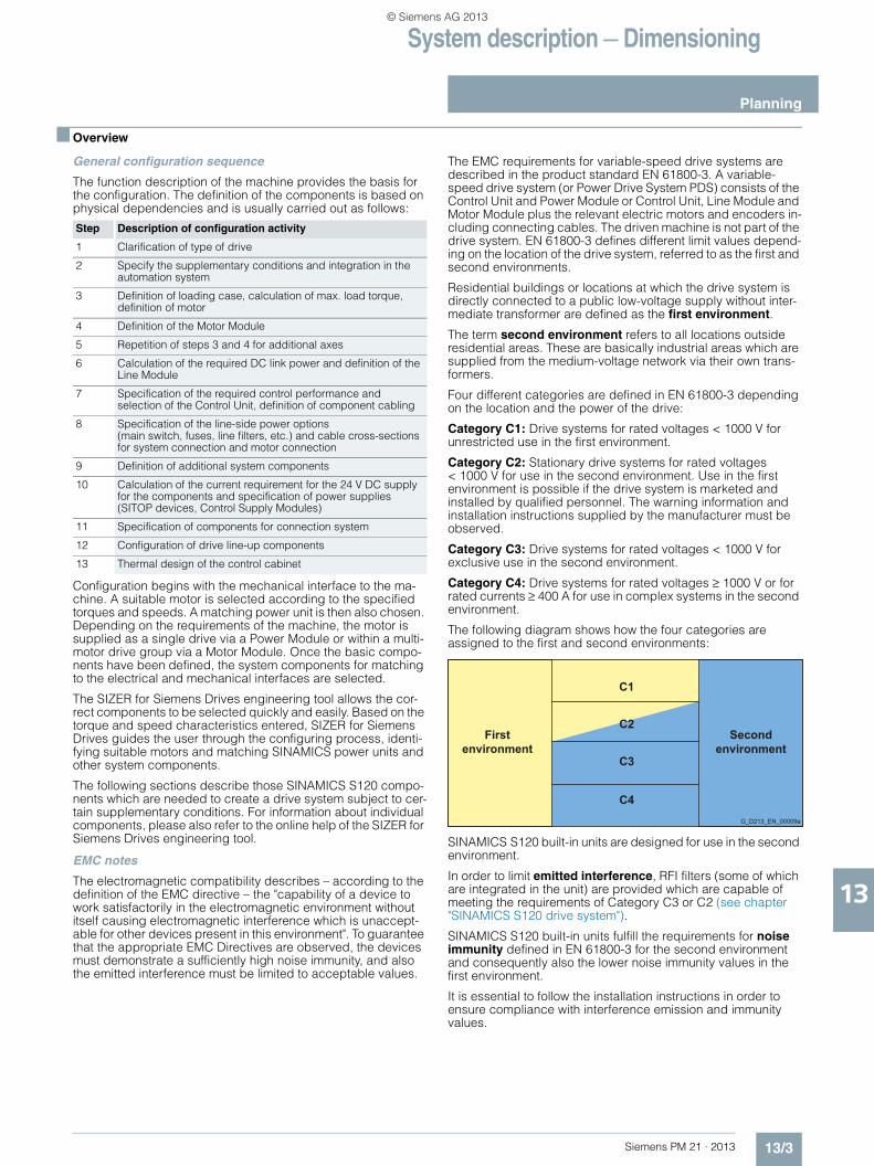
Four different categories are defined in EN 61800-3 depending on the location and the power of the drive:
Category C1: Drive systems for rated voltages < 1000 V for unrestricted use in the first environment.
Category C2: Stationary drive systems for rated voltages < 1000 V for use in the second environment. Use in the first environment is possible if the drive system is marketed and installed by qualified personnel. The warning information and installation instructions supplied by the manufacturer must be observed.
Category C3: Drive systems for rated voltages < 1000 V for exclusive use in the second environment.
Category C4: Drive systems for rated voltages ≥ 1000 V or for rated currents ≥ 400 A for use in complex systems in the second environment.
The following diagram shows how the four categories are assigned to the first and second environments:
SINAMICS S120 built-in units are designed for use in the second environment.
In order to limit emitted interference, RFI filters (some of which are integrated in the unit) are provided which are capable of meeting the requirements of Category C3 or C2 (see chapter "SINAMICS S120 drive system").
SINAMICS S120 built-in units fulfill the requirements for noise immunity defined in EN 61800-3 for the second environment and consequently also the lower noise immunity values in the first environment.
It is essential to follow the installation instructions in order to ensure compliance with interference emission and immunity values.
Step Description of configuration activity
1 Clarification of type of drive
2 Specify the supplementary conditions and integration in the automation system
3 Definition of loading case, calculation of max. load torque, definition of motor
4 Definition of the Motor Module
5 Repetition of steps 3 and 4 for additional axes
6 Calculation of the required DC link power and definition of the Line Module
7 Specification of the required control performance and selection of the Control Unit, definition of component cabling
8 Specification of the line-side power options (main switch, fuses, line filters, etc.) and cable cross-sections for system connection and motor connection
9 Definition of additional system components
10 Calculation of the current requirement for the 24 V DC supply for the components and specification of power supplies (SITOP devices, Control Supply Modules)
11 Specification of components for connection system
12 Configuration of drive line-up components
13 Thermal design of the control cabinet
G_D213_EN_00009a
Firstenvironment
Secondenvironment
C1
C2
C4
C3
© Siemens AG 2013

System description — Dimensioning
SINAMICS S120 Control Units
13/4 Siemens PM 21 · 2013
13
■ Overview
Simple technological tasks can be carried out by the SINAMICS S120 Control Unit itself. The CU320-2 Control Unit is available for multi-axis applications and the CU310-2 Control Unit for single drives.
Sophisticated Motion Control tasks are best supported by the powerful SIMOTION D Control Units (D410-2, D425-2, D435-2, D445-2, D455-2) with graded performance.
Each of these Control Units is based on an object-oriented SINAMICS S120 standard firmware which contains all the most popular V/f control modes and closed-loop control variants, that can be scaled to meet even the most advanced performance requirements.
The following are ready-to-configure drive objects (drive controls):• The control for a line infeed:
Infeed Control• The control for the broad scope of rugged asynchronous
(induction) motors and torque motors, including sensorless: Vector Control
• The control for permanent magnet synchronous and servo asynchronous motors with demanding dynamic requirements: Servo Control
All these control variants are based on the principle of field-oriented, closed-loop vector control.
The most commonly used V/f control modes are stored in the Vector Control drive object and are ideal for implementing even simple applications such as, for example, group drives with SIEMOSYN motors.
Guide to selecting a closed-loop control variant
The two tables below titled "Closed-loop control characteristics" and "Performance characteristics" are provided to help users select the "right" type of closed-loop control.
The drive control functions integrated in the SIMOTION D410-2, D4x5-2 and CX32-2 Control Units are based on the drive control of the SINAMICS S120 Control Units (firmware version V4.x), although there is a slight difference in functionality. For example, the basic positioner (EPos) and the Basic Operator Panel BOP20 are not supported.• SIMOTION D410-2 is based on the output control of a
SINAMICS S120 Control Unit CU310-2 (62.5 µs current controller clock cycle is not supported by SIMOTION D410-2)
• SIMOTION D4x5-2/CX32-2 is based on the output control of a SINAMICS S120 Control Unit CU320-2
For further information, see the SIMOTION and SINAMICS documentation.
Closed-loop control characteristics SINAMICS S
Criteria for assessing control quality
Explanations, definitions
Rise time The rise time is the period which elapses between an abrupt change in a setpoint and the moment the actual value first reaches the tolerance band (2 %) around the setpoint.The dead time is the period which elapses between the abrupt change in the setpoint and the moment the actual value begins to increase. The dead time is partially determined by the read-in, processing and output cycles of the digital closed-loop control. Where the dead time constitutes a significant proportion of the rise time, it must be separately identified.
Characteris-tic angular frequency -3 dB
The limit frequency is a measure of the dynamic response of a closed-loop control. A pure sinusoidal set-point is input to calculate the limit frequency; no part of the control loop must reach the limit. The actual value is measured under steady-state conditions and the ratio between the amplitudes of actual value and setpoint is recorded. -3 dB limit frequency: Frequency at which the absolute value of the actual value drops by 3 dB (to 71 %) for the first time. The closed-loop control can manage frequen-cies up to this value and remain stable.
Ripple The ripple is the undesirable characteristic of the actual value which is superimposed on the mean value (useful signal). Oscillating torque is another term used in rela-tion to torque. Typical oscillating torques are caused by motor slot grids, by limited encoder resolution or by the limited resolution of the voltage control of the IGBT power unit. The torque ripple is also reflected in the speed ripple as being indirectly proportional to the mass inertia of the drive.
Accuracy Accuracy is a measure of the magnitude of the average, repeatable deviation between the actual value and set-point under nominal conditions. Deviations between the actual value and setpoint are caused by internal inaccu-racies in the measuring and control systems. External disturbances, such as temperature or speed, are not included in the accuracy assessment. The closed-loop and open-loop controls should be optimized with respect to the relevant variable.
© Siemens AG 2013
System description — Dimensioning
SINAMICS S120 Control Units
13/5Siemens PM 21 · 2013
13
■ Configuration
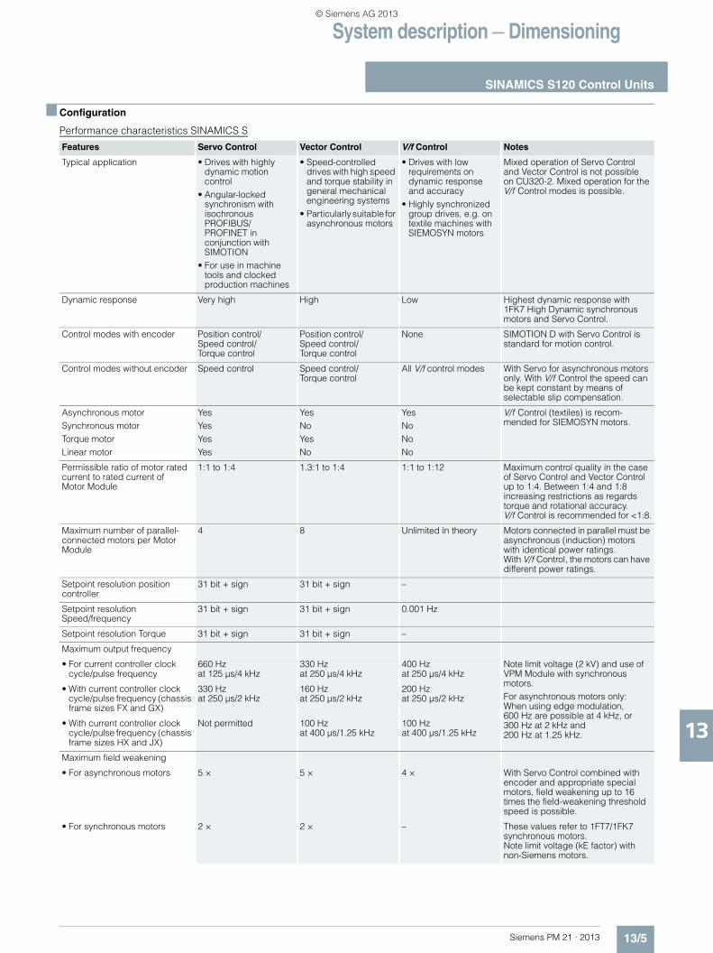
Performance characteristics SINAMICS S
Features Servo Control Vector Control V/f Control Notes
Typical application • Drives with highly dynamic motion control
• Angular-locked synchronism with isochronous PROFIBUS/PROFINET in conjunction with SIMOTION
• For use in machine tools and clocked production machines
• Speed-controlled drives with high speed and torque stability in general mechanical engineering systems
• Particularly suitable for asynchronous motors
• Drives with low requirements on dynamic response and accuracy
• Highly synchronized group drives, e.g. on textile machines with SIEMOSYN motors
Mixed operation of Servo Control and Vector Control is not possible on CU320-2. Mixed operation for the V/f Control modes is possible.
Dynamic response Very high High Low Highest dynamic response with 1FK7 High Dynamic synchronous motors and Servo Control.
Control modes with encoder Position control/Speed control/Torque control
Position control/Speed control/Torque control
None SIMOTION D with Servo Control is standard for motion control.
Control modes without encoder Speed control Speed control/Torque control
All V/f control modes With Servo for asynchronous motors only. With V/f Control the speed can be kept constant by means of selectable slip compensation.
Asynchronous motorSynchronous motorTorque motorLinear motor
YesYesYesYes
YesNoYesNo
YesNoNoNo
V/f Control (textiles) is recom-mended for SIEMOSYN motors.
Permissible ratio of motor rated current to rated current of Motor Module
1:1 to 1:4 1.3:1 to 1:4 1:1 to 1:12 Maximum control quality in the case of Servo Control and Vector Control up to 1:4. Between 1:4 and 1:8 increasing restrictions as regards torque and rotational accuracy. V/f Control is recommended for <1:8.
Maximum number of parallel-connected motors per Motor Module
4 8 Unlimited in theory Motors connected in parallel must be asynchronous (induction) motors with identical power ratings. With V/f Control, the motors can have different power ratings.
Setpoint resolution position controller
31 bit + sign 31 bit + sign –
Setpoint resolution Speed/frequency
31 bit + sign 31 bit + sign 0.001 Hz
Setpoint resolution Torque 31 bit + sign 31 bit + sign –
Maximum output frequency
• For current controller clock cycle/pulse frequency
660 Hz at 125 µs/4 kHz
330 Hz at 250 µs/4 kHz
400 Hz at 250 µs/4 kHz
Note limit voltage (2 kV) and use of VPM Module with synchronous motors. For asynchronous motors only: When using edge modulation, 600 Hz are possible at 4 kHz, or 300 Hz at 2 kHz and 200 Hz at 1.25 kHz.
• With current controller clock cycle/pulse frequency (chassis frame sizes FX and GX)
330 Hz at 250 µs/2 kHz
160 Hz at 250 µs/2 kHz
200 Hz at 250 µs/2 kHz
• With current controller clock cycle/pulse frequency (chassis frame sizes HX and JX)
Not permitted 100 Hz at 400 µs/1.25 kHz
100 Hz at 400 µs/1.25 kHz
Maximum field weakening
• For asynchronous motors 5 × 5 × 4 × With Servo Control combined with encoder and appropriate special motors, field weakening up to 16 times the field-weakening threshold speed is possible.
• For synchronous motors 2 × 2 × – These values refer to 1FT7/1FK7 synchronous motors.Note limit voltage (kE factor) with non-Siemens motors.
© Siemens AG 2013
System description — Dimensioning
SINAMICS S120 Control Units
13/6 Siemens PM 21 · 2013
13
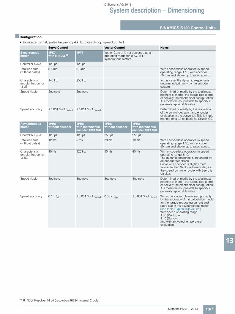
■ Configuration
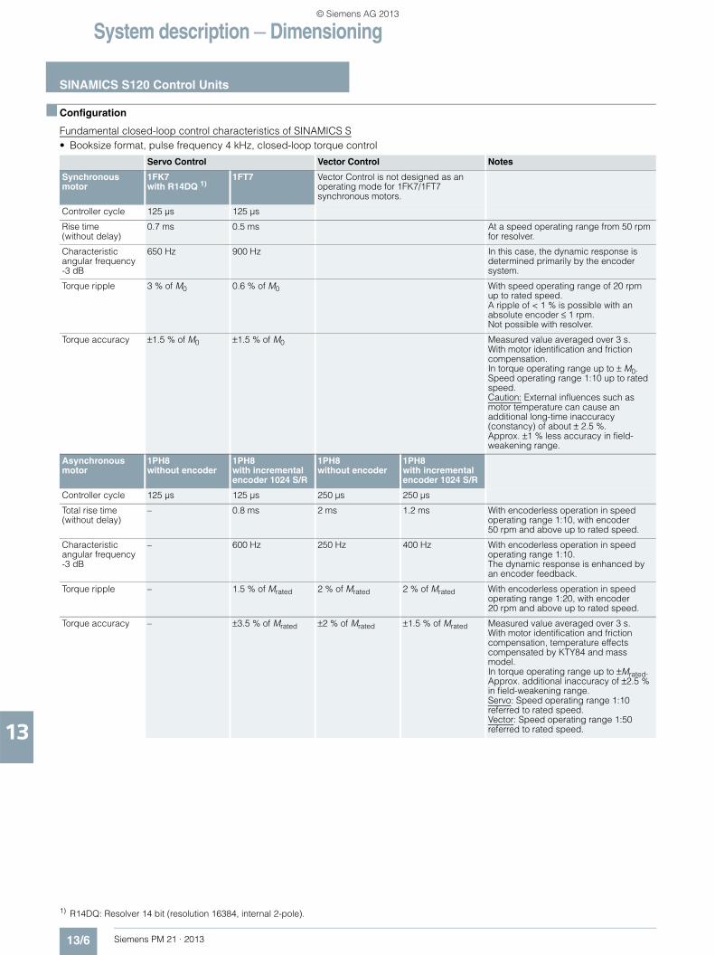
Fundamental closed-loop control characteristics of SINAMICS S• Booksize format, pulse frequency 4 kHz, closed-loop torque control
Servo Control Vector Control Notes
Synchronous motor
1FK7 with R14DQ 1)
1FT7 Vector Control is not designed as an operating mode for 1FK7/1FT7 synchronous motors.
Controller cycle 125 µs 125 µs
Rise time (without delay)
0.7 ms 0.5 ms At a speed operating range from 50 rpm for resolver.
Characteristic angular frequency -3 dB
650 Hz 900 Hz In this case, the dynamic response is determined primarily by the encoder system.
Torque ripple 3 % of M0 0.6 % of M0 With speed operating range of 20 rpm up to rated speed.A ripple of < 1 % is possible with an absolute encoder ≤ 1 rpm.Not possible with resolver.
Torque accuracy ±1.5 % of M0 ±1.5 % of M0 Measured value averaged over 3 s.With motor identification and friction compensation. In torque operating range up to ± M0.Speed operating range 1:10 up to rated speed.Caution: External influences such as motor temperature can cause an additional long-time inaccuracy (constancy) of about ± 2.5 %. Approx. ±1 % less accuracy in field-weakening range.
Asynchronous motor
1PH8 without encoder
1PH8 with incremental encoder 1024 S/R
1PH8 without encoder
1PH8 with incremental encoder 1024 S/R
Controller cycle 125 µs 125 µs 250 µs 250 µs
Total rise time (without delay)
– 0.8 ms 2 ms 1.2 ms With encoderless operation in speed operating range 1:10, with encoder 50 rpm and above up to rated speed.
Characteristic angular frequency -3 dB
– 600 Hz 250 Hz 400 Hz With encoderless operation in speed operating range 1:10.The dynamic response is enhanced by an encoder feedback.
Torque ripple – 1.5 % of Mrated 2 % of Mrated 2 % of Mrated With encoderless operation in speed operating range 1:20, with encoder 20 rpm and above up to rated speed.
Torque accuracy – ±3.5 % of Mrated ±2 % of Mrated ±1.5 % of Mrated Measured value averaged over 3 s.With motor identification and friction compensation, temperature effects compensated by KTY84 and mass model.In torque operating range up to ±Mrated.Approx. additional inaccuracy of ±2.5 % in field-weakening range.Servo: Speed operating range 1:10 referred to rated speed.Vector: Speed operating range 1:50 referred to rated speed.
1) R14DQ: Resolver 14 bit (resolution 16384, internal 2-pole).
© Siemens AG 2013
System description — Dimensioning
SINAMICS S120 Control Units
13/7Siemens PM 21 · 2013
13
■ Configuration
• Booksize format, pulse frequency 4 kHz, closed-loop speed control
Servo Control Vector Control Notes
Synchronous motor
1FK7 with R14DQ 1)
1FT7 Vector Control is not designed as an operating mode for 1FK7/1FT7 synchronous motors.
Controller cycle 125 µs 125 µs
Total rise time (without delay)
3.5 ms 2.3 ms With encoderless operation in speed operating range 1:10, with encoder 50 rpm and above up to rated speed.
Characteristic angular frequency -3 dB
140 Hz 250 Hz In this case, the dynamic response is determined primarily by the encoder system.
Speed ripple See note See note Determined primarily by the total mass moment of inertia, the torque ripple and especially the mechanical configuration. It is therefore not possible to specify a generally applicable value.
Speed accuracy ≤ 0.001 % of nrated ≤ 0.001 % of nrated Determined primarily by the resolution of the control deviation and encoder evaluation in the converter. This is imple-mented on a 32 bit basis for SINAMICS.
Asynchronous motor
1PH8 without encoder
1PH8 with incremental encoder 1024 S/R
1PH8 without encoder
1PH8 with incremental encoder 1024 S/R
Controller cycle 125 µs 125 µs 250 µs 250 µs
Total rise time (without delay)
12 ms 5 ms 20 ms 10 ms With encoderless operation in speed operating range 1:10, with encoder 50 rpm and above up to rated speed.
Characteristic angular frequency -3 dB
40 Hz 120 Hz 50 Hz 80 Hz With encoderless operation in speed operating range 1:10.The dynamic response is enhanced by an encoder feedback.Servo with encoder is slightly more favorable than Vector with encoder, as the speed controller cycle with Servo is quicker.
Speed ripple See note See note See note See note Determined primarily by the total mass moment of inertia, the torque ripple and especially the mechanical configuration.It is therefore not possible to specify a generally applicable value.
Speed accuracy 0.1 × fslip ≤ 0.001 % of nrated 0.05 × fslip ≤ 0.001 % of nrated Without encoder: Determined primarily by the accuracy of the calculation model for the torque-producing current and rated slip of the asynchronous motor (see table "Typical slip values").With speed operating range 1:50 (Vector) or 1:10 (Servo) and with activated temperature evaluation.
1) R14DQ: Resolver 14 bit (resolution 16384, internal 2-pole).
© Siemens AG 2013
System description — Dimensioning
SINAMICS S120 Control Units
13/8 Siemens PM 21 · 2013
13
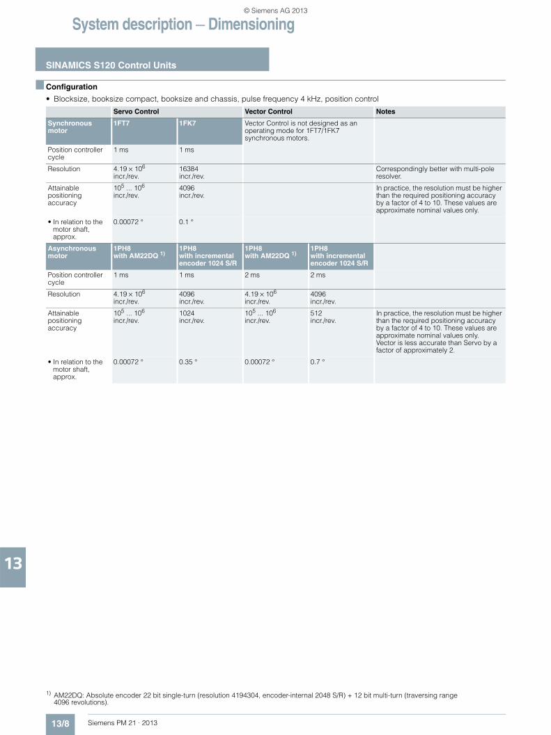
■ Configuration
• Blocksize, booksize compact, booksize and chassis, pulse frequency 4 kHz, position control
Servo Control Vector Control Notes
Synchronous motor
1FT7 1FK7 Vector Control is not designed as an operating mode for 1FT7/1FK7 synchronous motors.
Position controller cycle
1 ms 1 ms
Resolution 4.19 × 10⁶
incr./rev.16384incr./rev.
Correspondingly better with multi-pole resolver.
Attainable positioning accuracy
105 ... 106
incr./rev.4096incr./rev.
In practice, the resolution must be higher than the required positioning accuracy by a factor of 4 to 10. These values are approximate nominal values only.
• In relation to the motor shaft, approx.
0.00072 ° 0.1 °
Asynchronous motor
1PH8 with AM22DQ 1)
1PH8 with incremental encoder 1024 S/R
1PH8 with AM22DQ 1)
1PH8 with incremental encoder 1024 S/R
Position controller cycle
1 ms 1 ms 2 ms 2 ms
Resolution 4.19 × 10⁶
incr./rev.4096incr./rev.
4.19 × 10⁶
incr./rev.4096incr./rev.
Attainable positioning accuracy
105 ... 106
incr./rev.1024incr./rev.
105 ... 106
incr./rev.512incr./rev.
In practice, the resolution must be higher than the required positioning accuracy by a factor of 4 to 10. These values are approximate nominal values only. Vector is less accurate than Servo by a factor of approximately 2.
• In relation to the motor shaft, approx.
0.00072 ° 0.35 ° 0.00072 ° 0.7 °
1) AM22DQ: Absolute encoder 22 bit single-turn (resolution 4194304, encoder-internal 2048 S/R) + 12 bit multi-turn (traversing range 4096 revolutions).
© Siemens AG 2013
System description — Dimensioning
SINAMICS S120 Control Units
13/9Siemens PM 21 · 2013
13
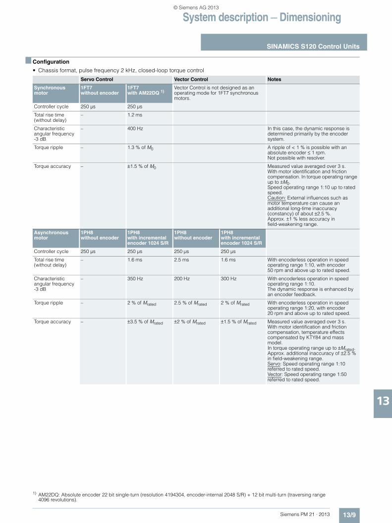
■ Configuration
• Chassis format, pulse frequency 2 kHz, closed-loop torque control
Servo Control Vector Control Notes
Synchronous motor
1FT7without encoder
1FT7with AM22DQ 1)
Vector Control is not designed as an operating mode for 1FT7 synchronous motors.
Controller cycle 250 µs 250 µs
Total rise time (without delay)
– 1.2 ms
Characteristic angular frequency -3 dB
– 400 Hz In this case, the dynamic response is determined primarily by the encoder system.
Torque ripple – 1.3 % of M0 A ripple of < 1 % is possible with an absolute encoder ≤ 1 rpm.Not possible with resolver.
Torque accuracy – ±1.5 % of M0 Measured value averaged over 3 s.With motor identification and friction compensation. In torque operating range up to ±M0.Speed operating range 1:10 up to rated speed.Caution: External influences such as motor temperature can cause an additional long-time inaccuracy (constancy) of about ±2.5 %.Approx. ±1 % less accuracy in field-weakening range.
Asynchronous motor
1PH8 without encoder
1PH8 with incremental encoder 1024 S/R
1PH8 without encoder
1PH8 with incremental encoder 1024 S/R
Controller cycle 250 µs 250 µs 250 µs 250 µs
Total rise time (without delay)
– 1.6 ms 2.5 ms 1.6 ms With encoderless operation in speed operating range 1:10, with encoder 50 rpm and above up to rated speed.
Characteristic angular frequency -3 dB
– 350 Hz 200 Hz 300 Hz With encoderless operation in speed operating range 1:10.The dynamic response is enhanced by an encoder feedback.
Torque ripple – 2 % of Mrated 2.5 % of Mrated 2 % of Mrated With encoderless operation in speed operating range 1:20, with encoder 20 rpm and above up to rated speed.
Torque accuracy – ±3.5 % of Mrated ±2 % of Mrated ±1.5 % of Mrated Measured value averaged over 3 s.With motor identification and friction compensation, temperature effects compensated by KTY84 and mass model.In torque operating range up to ±Mrated. Approx. additional inaccuracy of ±2.5 % in field-weakening range.Servo: Speed operating range 1:10 referred to rated speed.Vector: Speed operating range 1:50 referred to rated speed.
1) AM22DQ: Absolute encoder 22 bit single-turn (resolution 4194304, encoder-internal 2048 S/R) + 12 bit multi-turn (traversing range 4096 revolutions).
© Siemens AG 2013
System description — Dimensioning
SINAMICS S120 Control Units
13/10 Siemens PM 21 · 2013
13
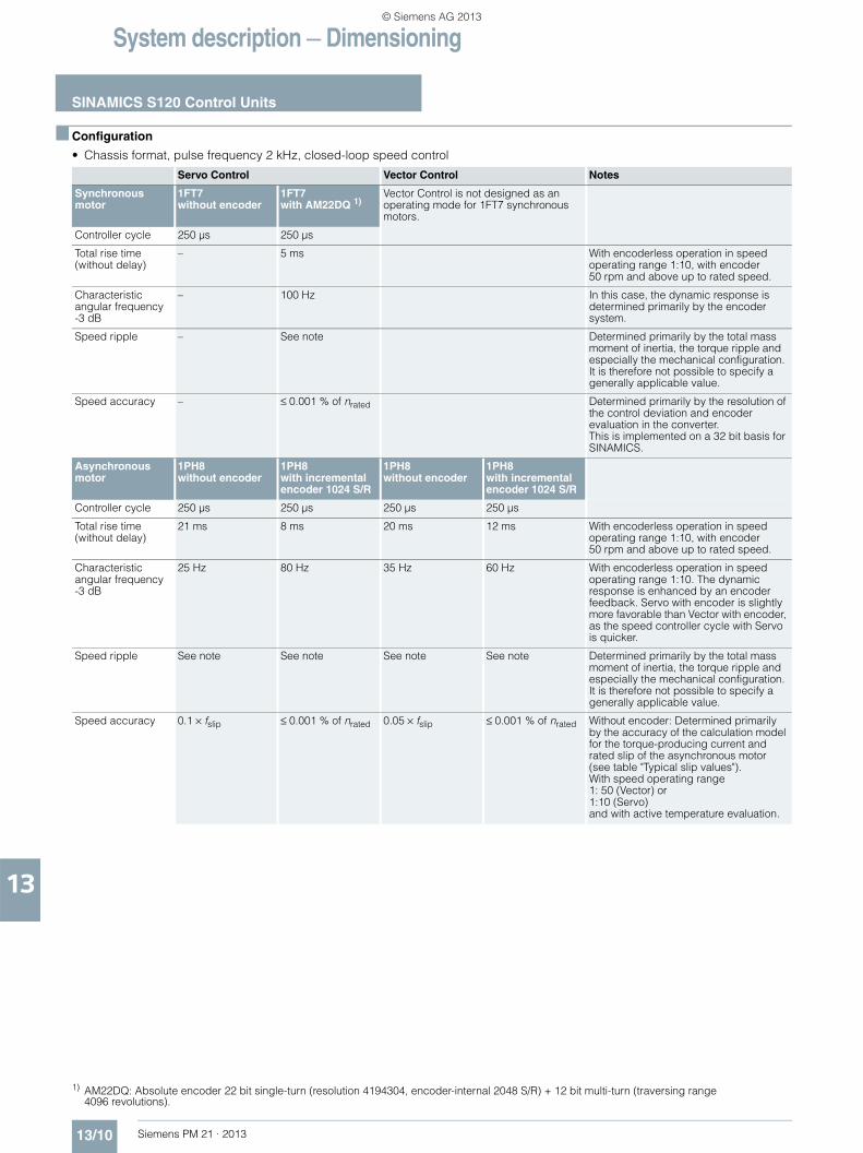
■ Configuration
• Chassis format, pulse frequency 2 kHz, closed-loop speed control
Servo Control Vector Control Notes
Synchronous motor
1FT7without encoder
1FT7with AM22DQ 1)
Vector Control is not designed as an operating mode for 1FT7 synchronous motors.
Controller cycle 250 µs 250 µs
Total rise time (without delay)
– 5 ms With encoderless operation in speed operating range 1:10, with encoder 50 rpm and above up to rated speed.
Characteristic angular frequency-3 dB
– 100 Hz In this case, the dynamic response is determined primarily by the encoder system.
Speed ripple – See note Determined primarily by the total mass moment of inertia, the torque ripple and especially the mechanical configuration.It is therefore not possible to specify a generally applicable value.
Speed accuracy – ≤ 0.001 % of nrated Determined primarily by the resolution of the control deviation and encoder evaluation in the converter. This is implemented on a 32 bit basis for SINAMICS.
Asynchronous motor
1PH8 without encoder
1PH8 with incremental encoder 1024 S/R
1PH8 without encoder
1PH8 with incremental encoder 1024 S/R
Controller cycle 250 µs 250 µs 250 µs 250 µs
Total rise time (without delay)
21 ms 8 ms 20 ms 12 ms With encoderless operation in speed operating range 1:10, with encoder 50 rpm and above up to rated speed.
Characteristic angular frequency -3 dB
25 Hz 80 Hz 35 Hz 60 Hz With encoderless operation in speed operating range 1:10. The dynamic response is enhanced by an encoder feedback. Servo with encoder is slightly more favorable than Vector with encoder, as the speed controller cycle with Servo is quicker.
Speed ripple See note See note See note See note Determined primarily by the total mass moment of inertia, the torque ripple and especially the mechanical configuration.It is therefore not possible to specify a generally applicable value.
Speed accuracy 0.1 × fslip ≤ 0.001 % of nrated 0.05 × fslip ≤ 0.001 % of nrated Without encoder: Determined primarily by the accuracy of the calculation model for the torque-producing current and rated slip of the asynchronous motor (see table "Typical slip values").With speed operating range 1: 50 (Vector) or 1:10 (Servo) and with active temperature evaluation.
1) AM22DQ: Absolute encoder 22 bit single-turn (resolution 4194304, encoder-internal 2048 S/R) + 12 bit multi-turn (traversing range 4096 revolutions).
© Siemens AG 2013
System description — Dimensioning
SINAMICS S120 Control Units
13/11Siemens PM 21 · 2013
13
■ Configuration
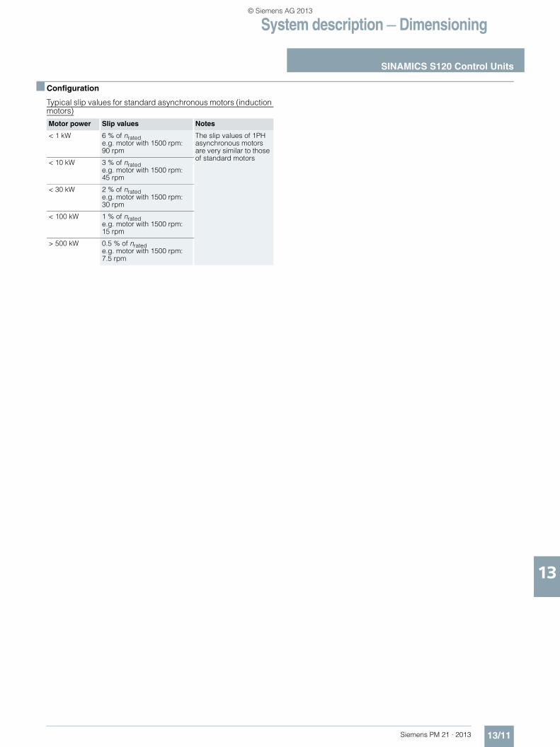
Typical slip values for standard asynchronous motors (induction motors)
Motor power Slip values Notes
< 1 kW 6 % of nrated e.g. motor with 1500 rpm: 90 rpm
The slip values of 1PH asynchronous motors are very similar to those of standard motors
< 10 kW 3 % of nrated e.g. motor with 1500 rpm: 45 rpm
< 30 kW 2 % of nrated e.g. motor with 1500 rpm: 30 rpm
< 100 kW 1 % of nrated e.g. motor with 1500 rpm: 15 rpm
> 500 kW 0.5 % of nrated e.g. motor with 1500 rpm: 7.5 rpm
© Siemens AG 2013
System description — Dimensioning
SINAMICS S120 Control Units
13/12 Siemens PM 21 · 2013
13
■ Configuration
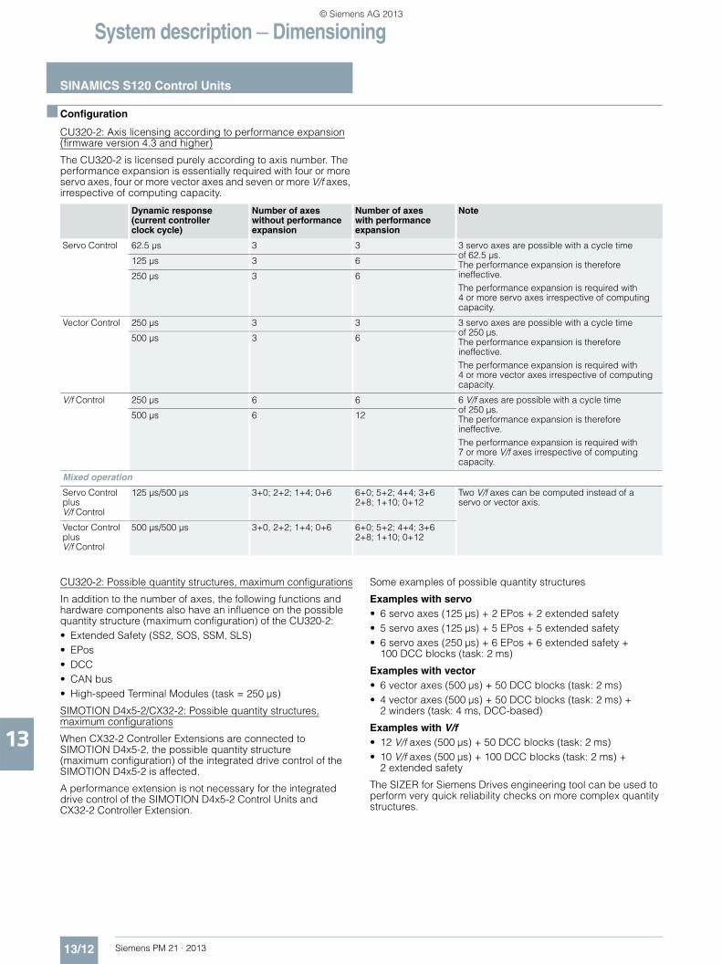
CU320-2: Axis licensing according to performance expansion(firmware version 4.3 and higher)
The CU320-2 is licensed purely according to axis number. The performance expansion is essentially required with four or more servo axes, four or more vector axes and seven or more V/f axes, irrespective of computing capacity.
CU320-2: Possible quantity structures, maximum configurations
In addition to the number of axes, the following functions and hardware components also have an influence on the possible quantity structure (maximum configuration) of the CU320-2:• Extended Safety (SS2, SOS, SSM, SLS)• EPos• DCC• CAN bus• High-speed Terminal Modules (task = 250 µs)
SIMOTION D4x5-2/CX32-2: Possible quantity structures,maximum configurations
When CX32-2 Controller Extensions are connected to SIMOTION D4x5-2, the possible quantity structure (maximum configuration) of the integrated drive control of the SIMOTION D4x5-2 is affected.
A performance extension is not necessary for the integrated drive control of the SIMOTION D4x5-2 Control Units and CX32-2 Controller Extension.
Some examples of possible quantity structures
Examples with servo • 6 servo axes (125 µs) + 2 EPos + 2 extended safety• 5 servo axes (125 µs) + 5 EPos + 5 extended safety• 6 servo axes (250 µs) + 6 EPos + 6 extended safety +
100 DCC blocks (task: 2 ms)
Examples with vector • 6 vector axes (500 µs) + 50 DCC blocks (task: 2 ms)• 4 vector axes (500 µs) + 50 DCC blocks (task: 2 ms) +
2 winders (task: 4 ms, DCC-based)
Examples with V/f• 12 V/f axes (500 µs) + 50 DCC blocks (task: 2 ms)• 10 V/f axes (500 µs) + 100 DCC blocks (task: 2 ms) +
2 extended safety
The SIZER for Siemens Drives engineering tool can be used to perform very quick reliability checks on more complex quantity structures.
Dynamic response (current controller clock cycle)
Number of axes without performance expansion
Number of axes with performance expansion
Note
Servo Control 62.5 µs 3 3 3 servo axes are possible with a cycle time of 62.5 µs.The performance expansion is therefore ineffective.The performance expansion is required with 4 or more servo axes irrespective of computing capacity.
125 µs 3 6
250 µs 3 6
Vector Control 250 µs 3 3 3 servo axes are possible with a cycle time of 250 µs.The performance expansion is therefore ineffective.The performance expansion is required with 4 or more vector axes irrespective of computing capacity.
500 µs 3 6
V/f Control 250 µs 6 6 6 V/f axes are possible with a cycle time of 250 µs.The performance expansion is therefore ineffective.The performance expansion is required with 7 or more V/f axes irrespective of computing capacity.
500 µs 6 12
Mixed operation
Servo Controlplus V/f Control
125 µs/500 µs 3+0; 2+2; 1+4; 0+6 6+0; 5+2; 4+4; 3+6 2+8; 1+10; 0+12
Two V/f axes can be computed instead of a servo or vector axis.
Vector Controlplus V/f Control
500 µs/500 µs 3+0, 2+2; 1+4; 0+6 6+0; 5+2; 4+4; 3+6 2+8; 1+10; 0+12
© Siemens AG 2013
System description — Dimensioning
SINAMICS S120 Control Units
13/13Siemens PM 21 · 2013
13
■ Configuration
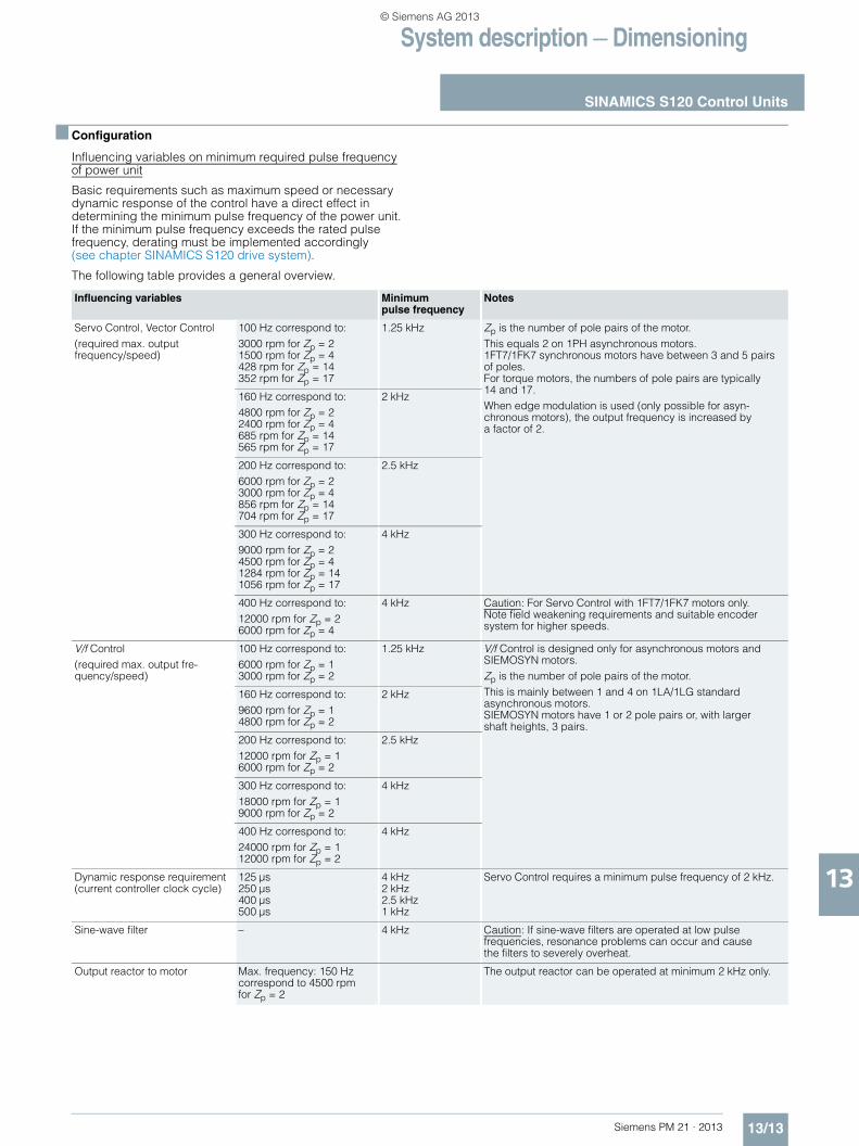
Influencing variables on minimum required pulse frequencyof power unit
Basic requirements such as maximum speed or necessary dynamic response of the control have a direct effect in determining the minimum pulse frequency of the power unit. If the minimum pulse frequency exceeds the rated pulse frequency, derating must be implemented accordingly (see chapter SINAMICS S120 drive system).
The following table provides a general overview.
Influencing variables Minimum pulse frequency
Notes
Servo Control, Vector Control(required max. output frequency/speed)
100 Hz correspond to:3000 rpm for Zp = 21500 rpm for Zp = 4428 rpm for Zp = 14352 rpm for Zp = 17
1.25 kHz Zp is the number of pole pairs of the motor.This equals 2 on 1PH asynchronous motors.1FT7/1FK7 synchronous motors have between 3 and 5 pairs of poles.For torque motors, the numbers of pole pairs are typically 14 and 17.When edge modulation is used (only possible for asyn-chronous motors), the output frequency is increased by a factor of 2.
160 Hz correspond to:4800 rpm for Zp = 22400 rpm for Zp = 4685 rpm for Zp = 14565 rpm for Zp = 17
2 kHz
200 Hz correspond to:6000 rpm for Zp = 23000 rpm for Zp = 4856 rpm for Zp = 14704 rpm for Zp = 17
2.5 kHz
300 Hz correspond to:9000 rpm for Zp = 24500 rpm for Zp = 41284 rpm for Zp = 141056 rpm for Zp = 17
4 kHz
400 Hz correspond to:12000 rpm for Zp = 26000 rpm for Zp = 4
4 kHz Caution: For Servo Control with 1FT7/1FK7 motors only. Note field weakening requirements and suitable encoder system for higher speeds.
V/f Control(required max. output fre-quency/speed)
100 Hz correspond to:6000 rpm for Zp = 13000 rpm for Zp = 2
1.25 kHz V/f Control is designed only for asynchronous motors and SIEMOSYN motors.Zp is the number of pole pairs of the motor.This is mainly between 1 and 4 on 1LA/1LG standard asynchronous motors. SIEMOSYN motors have 1 or 2 pole pairs or, with larger shaft heights, 3 pairs.
160 Hz correspond to:9600 rpm for Zp = 14800 rpm for Zp = 2
2 kHz
200 Hz correspond to:12000 rpm for Zp = 16000 rpm for Zp = 2
2.5 kHz
300 Hz correspond to:18000 rpm for Zp = 19000 rpm for Zp = 2
4 kHz
400 Hz correspond to:24000 rpm for Zp = 112000 rpm for Zp = 2
4 kHz
Dynamic response requirement (current controller clock cycle)
125 µs250 µs400 µs500 µs
4 kHz2 kHz2.5 kHz1 kHz
Servo Control requires a minimum pulse frequency of 2 kHz.
Sine-wave filter – 4 kHz Caution: If sine-wave filters are operated at low pulse frequencies, resonance problems can occur and cause the filters to severely overheat.
Output reactor to motor Max. frequency: 150 Hz correspond to 4500 rpm for Zp = 2
The output reactor can be operated at minimum 2 kHz only.
© Siemens AG 2013
System description — Dimensioning
SINAMICS S120 Control Units
13/14 Siemens PM 21 · 2013
13
■ Configuration
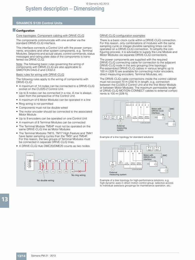
Core topologies: Component cabling with DRIVE-CLiQ
The components communicate with one another via the standard DRIVE-CLiQ interface.
This interface connects a Control Unit with the power compo-nents, encoders and other system components, e.g. Terminal Modules. Setpoints and actual values, control commands, status messages and rating plate data of the components is trans-ferred via DRIVE CLiQ.
Note: The following basic rules governing the wiring of components with DRIVE-CLiQ are also applicable to SIMOTION D4x5-2 and CX32-2.
Basic rules for wiring with DRIVE-CLiQ
The following rules apply to the wiring of components with DRIVE-CLiQ:• A maximum of 14 nodes can be connected to a DRIVE-CLiQ
socket on the CU320-2 Control Unit.• Up to 8 nodes can be connected in a row. A row is always
seen from the perspective of the Control Unit.• A maximum of 6 Motor Modules can be operated in a line• Ring wiring is not permitted• Components must not be double-wired• The motor encoder should be connected to the associated
Motor Module• Up to 9 encoders can be operated on one Control Unit• A maximum of 8 Terminal Modules can be connected• The Terminal Module TM54F must not be operated on the
same DRIVE-CLiQ line as Motor Modules• The Terminal Modules TM15, TM17 High Feature and TM41
have faster sampling cycles than the TM31 and TM54F. For this reason, the two groups of Terminal Modules must be connected in separate DRIVE-CLiQ lines.
• A DRIVE-CLiQ Hub DMC20/DME20 counts as two nodes
DRIVE-CLiQ configuration examples
There is a basic clock cycle within a DRIVE-CLiQ connection. For this reason, only combinations of modules with the same sampling cycle or integer-divisible sampling times can be operated on a DRIVE-CLiQ connection. To simplify the con-figuring process, it is advisable to supply the Line Module and Motor Modules via separate DRIVE-CLiQ connections.
The power components are supplied with the required DRIVE-CLiQ connecting cable for connection to the adjacent DRIVE-CLiQ node in the axis grouping (line topology). Pre-assembled DRIVE-CLiQ cables in various lengths up to 100 m (328 ft) are available for connecting motor encoders, direct measuring encoders, Terminal Modules, etc.
The DRIVE-CLiQ cable connections inside the control cabinet must not exceed 70 m (230 ft) in length, e.g. connection between the CU320-2 Control Unit and the first Motor Module or between Motor Modules. The maximum permissible length of DRIVE-CLiQ MOTION-CONNECT cables to external compo-nents is 100 m (328 ft).
Example of a line topology for standard solutions
Example of a tree topology for high-performance solutions, e.g. high-dynamic axes in direct motion control group, selective access to individual axes/axis groupings for maintenance operation, etc.
CU320-2
12
X 103X 102X 101X 100
1 2 3 4 6 7
14
8
9 10 11
5
13
No ring wiring
No double wiring
G_D
212_
EN
_000
13b
TM31 TM31 SMC
CU320-2
SMC
Externalmeasuringsystem
Motor withDRIVE-CLiQinterface
G_D212_EN_00014b
Line Module
Motor Module
Motor Module
TM31 TM31
SMC
CU320-2
SMC
External measuring system
Motor withDRIVE-CLiQinterface
G_D212_EN_00015b
Line Module
Motor Module
Motor Module
© Siemens AG 2013

System description — Dimensioning
SINAMICS S120 Control Units
13/15Siemens PM 21 · 2013
13
■ Configuration
Preferred wiring of DRIVE-CLiQ connections illustrated by example of booksize format Active Line Module: Current controller clock cycle 250 µs.Motor Modules: 4 × Vector Control = 500 µs current controller clock cycle
Wiring illustrated by example of chassis format with different current controller clock cycles
Example of wiring: Power Modules can also be operated on a CU320-2 when connected via a CUA31
ControlUnit
M3~
M3~
M3~
M3~
ActiveLineModule
SingleMotorModule
SingleMotorModule
DoubleMotorModuleCU320-2
SensorModule
SensorModule
SensorModule
X202 X202 X202 X202 X203
X201 X201 X201 X201
X200 X200 X200 X200X100
X101
X102
X103
X500 X500 X500 X500SensorModule
Infeed Drive 1 Drive 2 Drive 3 Drive 4
G_D
211_
EN
_000
19a
ActiveLineModule
SingleMotorModuleCU320-2
X402 X402
X401 X401
X400 X400X100
X101
X102X103
SingleMotorModule
X402
X401
X400
ControlUnit
VoltageSensingModule
M3~
M3~
SensorModuleX500 X500Sensor
Module
Infeed Drive 1 Drive 2
Type Chassis F, GCurrent controller clock cycle = 250 µs
Type Chassis H, JCurrent controller clock cycle = 400 µs
G_D
211_
EN_0
0020
a
ControlUnit
ActiveLineModule
TM31
CU320-2
DoubleMotorModule
M3~
M3~
M3~
PowerModule
PowerModule
CUA31
M3~
SMC30
CUA31
Infeed Drive 1 Drive 2 Drive 3 Drive 4
G_D
211_
EN
_000
99a
© Siemens AG 2013

System description — Dimensioning
Motors
13/16 Siemens PM 21 · 2013
13
■ Configuration
Motor selection
The motor is selected on the basis of the required torque, which is defined by the application, e.g. traveling drives, hoisting drives, test stands, centrifuges, paper and rolling mill drives, feed drives or main spindle drives. Gear units for movement conversion or for adapting the motor speed and motor torque to the load conditions must also be considered.
As well as the load torque, which is determined by the applica-tion, the following mechanical data are among those required to calculate the torque to be provided by the motor:• Masses to be moved• Diameter of the drive wheel/diameter• Leadscrew pitch, gear ratios• Frictional resistance data• Mechanical efficiency• Traversing paths• Maximum velocity• Maximum acceleration and maximum deceleration• Cycle time
You must decide whether synchronous or asynchronous motors (induction motors) are to be used.
Synchronous motors should be selected for compact construc-tion volume, low rotor moment of inertia and therefore maximum dynamic response.
Asynchronous motors can be used to increase maximum speeds in the field-weakening range. Asynchronous motors (induction motors) for higher power ratings are also available.
The following factors are of prime importance during configuration:• The line supply configuration, when using specific types
of motor and/or line filters on IT systems (non-grounded systems)
• The ambient temperatures and the installation altitude of the motors and drive components
The motor-specific limiting characteristics provide the basis for defining the motors.
These define the torque or power characteristic over speed and take into account the motor limits based on the DC-link voltage of the Power Module or Motor Module. The DC-link voltage in turn is dependent on the line voltage and, with multi-motor drives, on the type of Line Module.
Typical speed/power graph for asynchronous motors
Torque characteristics of synchronous motors
For detail engineering information, please refer to the motor configuration manuals.
An updated overview of configuration manuals is available in a number of languages on the Internet at: www.siemens.com/motioncontrol
Follow menu items Support > Technical Documentation > Ordering Documentation > Printed Documentation or download at: Support > Technical Documentation > Download Documenta-tion > DOConWEB.
The SIZER for Siemens Drives engineering tool is available to support engineering.
n2
Pmax
S1
nmaxn
P
Voltage limiting characteristic
Constantpowerrange (field weakening range)
nrated
Prated
G_P
M21
_EN
_000
74a
Constanttorquerange
G_D
211_
EN
_002
71
nmax mech
n
nmax Inv
Mmax
Mmax Invwithout field weakening Field
weakening operation
M Voltage limiting characteristic without field weakening
Voltage limiting characteristic with field weakening
S3-25 %
S3-40 %S3-100 %
S1 (100 K)S1 (60 K)
© Siemens AG 2013
System description — Dimensioning
Power units
13/17Siemens PM 21 · 2013
13
■ Configuration
Overload capability
The power units of the Line Modules, Motor Modules and Power Modules are designed for brief overloads, i.e. the Modules are capable of supplying more than the rated current Irated for short periods. In this instance, the thermal capacity of the heat sink is utilized, allowing for the relevant thermal time constants. The power semiconductors and actual current sensing circuit are rated for a maximum current Imax, which must not be exceeded. The overload capability is determined by Imax, Irated and the ther-mal time constants. A number of characteristic duty cycles are defined in the technical specifications for the power units. The SIZER for Siemens Drives engineering tool calculates the load on the basis of a specified duty cycle with optional time charac-teristic and then identifies the power unit which is required.
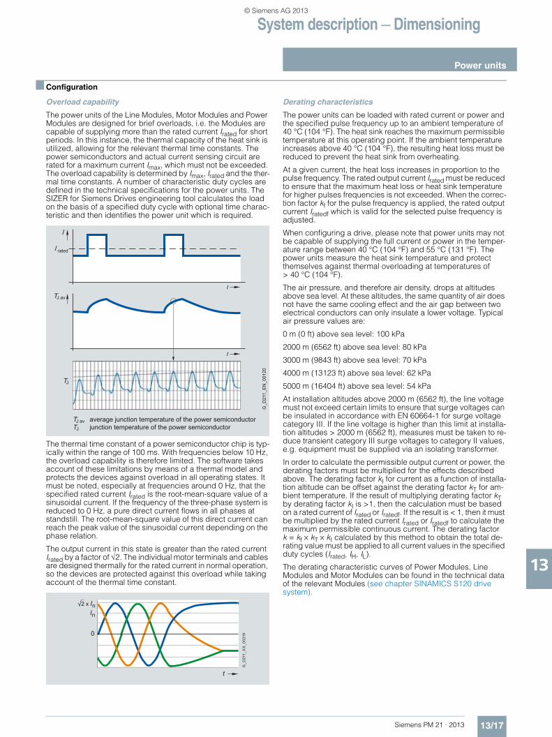
The thermal time constant of a power semiconductor chip is typ-ically within the range of 100 ms. With frequencies below 10 Hz, the overload capability is therefore limited. The software takes account of these limitations by means of a thermal model and protects the devices against overload in all operating states. It must be noted, especially at frequencies around 0 Hz, that the specified rated current Irated is the root-mean-square value of a sinusoidal current. If the frequency of the three-phase system is reduced to 0 Hz, a pure direct current flows in all phases at standstill. The root-mean-square value of this direct current can reach the peak value of the sinusoidal current depending on the phase relation.
The output current in this state is greater than the rated current Irated by a factor of √2. The individual motor terminals and cables are designed thermally for the rated current in normal operation, so the devices are protected against this overload while taking account of the thermal time constant.
Derating characteristics
The power units can be loaded with rated current or power and the specified pulse frequency up to an ambient temperature of 40 °C (104 °F). The heat sink reaches the maximum permissible temperature at this operating point. If the ambient temperature increases above 40 °C (104 °F), the resulting heat loss must be reduced to prevent the heat sink from overheating.
At a given current, the heat loss increases in proportion to the pulse frequency. The rated output current Irated must be reduced to ensure that the maximum heat loss or heat sink temperature for higher pulses frequencies is not exceeded. When the correc-tion factor kf for the pulse frequency is applied, the rated output current Iratedf which is valid for the selected pulse frequency is adjusted.
When configuring a drive, please note that power units may not be capable of supplying the full current or power in the temper-ature range between 40 °C (104 °F) and 55 °C (131 °F). The power units measure the heat sink temperature and protect themselves against thermal overloading at temperatures of > 40 °C (104 °F).
The air pressure, and therefore air density, drops at altitudes above sea level. At these altitudes, the same quantity of air does not have the same cooling effect and the air gap between two electrical conductors can only insulate a lower voltage. Typical air pressure values are:
0 m (0 ft) above sea level: 100 kPa
2000 m (6562 ft) above sea level: 80 kPa
3000 m (9843 ft) above sea level: 70 kPa
4000 m (13123 ft) above sea level: 62 kPa
5000 m (16404 ft) above sea level: 54 kPa
At installation altitudes above 2000 m (6562 ft), the line voltage must not exceed certain limits to ensure that surge voltages can be insulated in accordance with EN 60664-1 for surge voltage category III. If the line voltage is higher than this limit at installa-tion altitudes > 2000 m (6562 ft), measures must be taken to re-duce transient category III surge voltages to category II values, e.g. equipment must be supplied via an isolating transformer.
In order to calculate the permissible output current or power, the derating factors must be multiplied for the effects described above. The derating factor kI for current as a function of installa-tion altitude can be offset against the derating factor kT for am-bient temperature. If the result of multiplying derating factor kT by derating factor kI is >1, then the calculation must be based on a rated current of Irated or Iratedf. If the result is < 1, then it must be multiplied by the rated current Irated or Iratedf to calculate the maximum permissible continuous current. The derating factor k = kf × kT × kI calculated by this method to obtain the total de-rating value must be applied to all current values in the specified duty cycles (Irated, IH, IL).
The derating characteristic curves of Power Modules, Line Modules and Motor Modules can be found in the technical data of the relevant Modules (see chapter SINAMICS S120 drive system).
I
T
t
t
I rated
J av
TJ
T average junction temperature of the power semiconductorT junction temperature of the power semiconductor
J avJ
G_D
211_
EN
_001
20
0
In
√2 x In
t
G_D
211_
XX
_002
19
© Siemens AG 2013
System description — Dimensioning
Power units
13/18 Siemens PM 21 · 2013
13
■ Configuration
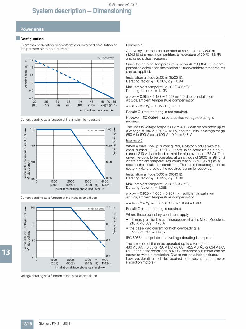
Examples of derating characteristic curves and calculation of the permissible output current:
Current derating as a function of the ambient temperature
Current derating as a function of the installation altitude
Voltage derating as a function of the installation altitude
Example 1
A drive system is to be operated at an altitude of 2500 m (8202 ft) at a maximum ambient temperature of 30 °C (86 °F) and rated pulse frequency.
Since the ambient temperature is below 40 °C (104 °F), a com-pensation calculation (installation altitude/ambient temperature) can be applied.
Installation altitude 2500 m (8202 ft): Derating factor kI = 0.965, kU = 0.94
Max. ambient temperature 30 °C (86 °F): Derating factor kT = 1.133
kI × kT = 0.965 × 1.133 = 1.093 1.0 due to installation altitude/ambient temperature compensation
k = kf × (kI × kT) = 1.0 × (1.0) = 1.0
Result: Current derating is not required.
However, IEC 60664-1 stipulates that voltage derating is required.
The units in voltage range 380 V to 480 V can be operated up to a voltage of 480 V × 0.94 = 451 V, and the units in voltage range 660 V to 690 V up to 690 V × 0.94 = 648 V.
Example 2
When a drive line-up is configured, a Motor Module with the order number 6SL3320-1TE32-1AA0 is selected (rated output current 210 A, base load current for high overload 178 A). The drive line-up is to be operated at an altitude of 3000 m (9843 ft) where ambient temperatures could reach 35 °C (95 °F) as a result of the installation conditions. The pulse frequency must be set to 4 kHz to provide the required dynamic response.
Installation altitude 3000 m (9843 ft): Derating factor kI = 0.925, kU = 0.88
Max. ambient temperature 35 °C (95 °F): Derating factor kT = 1.066
kI × kT = 0.925 × 1.066 = 0.987 insufficient installation altitude/ambient temperature compensation
k = kf × (kI × kT) = 0.82 × (0.925 × 1.066) = 0.809
Result: Current derating is required.
Where these boundary conditions apply,• the max. permissible continuous current of the Motor Module is:
210 A × 0.809 = 170 A• the base-load current for high overloading is:
178 A × 0.809 = 144 A
IEC 60664-1 stipulates that voltage derating is required.
The selected unit can be operated up to a voltage of 480 V 3 AC × 0.88 or 720 V DC × 0.88 = 422 V 3 AC or 634 V DC, i.e. under these conditions, a 400 V asynchronous motor can be operated without restriction. Due to the installation altitude, however, derating might be required for the asynchronous motor (induction motors).
G_D211_EN_00004c
Ambient temperature
(68) (77) (86) (95) (104) (113) (122) (131)(°F)
Der
atin
g fa
ctor
kT
1.3
1.2
1.1
1.0
0.9
0.82520 30 35 40 45 50 55°C
1000 2000 m0 3000 4000
100
95
90
85
(3281) (6562) (9843) (ft) (13124)
1.00
0.95
0.85
0.90
Der
atin
g fa
ctor
kI
Installation altitude above sea level
Per
mis
sibl
e co
ntin
uous
cur
rent
in %
of ra
ted
curr
ent
G_D211_EN_00005b
1000 2000 m0 3000 4000
100
90
80
70
(3281) (6562) (9843) (ft) (13124)
1.0
0.9
0.7
0.8
Der
atin
g fa
ctor
kU
Installation altitude above sea level
Per
mis
sibl
e in
put v
olta
ge in
%of
rate
d vo
ltage
G_D211_EN_00006b
© Siemens AG 2013
System description — Dimensioning
Power units
13/19Siemens PM 21 · 2013
13
■ Configuration
Selection of the Power Module or Motor Module
The Motor Module is selected initially on the basis of standstill current I0 100 K (rated current for winding temperature rise 100 K) for synchronous motors and the rated current Irated for asynchro-nous motors (induction motors), and is specified in the motor description. Dynamic overloads, e.g. during acceleration, must be taken into account by duty cycles and may demand a more powerful Power Module or Motor Module. In this context, it is also important to remember that the output current of the Power Mod-ule or Motor Module decreases as a function of installation alti-tude, ambient temperature and pulse frequency setting (see explanations of derating characteristics).
For an optimum configuration, the effective motor current Iload calculated from the duty cycle is replicated on the Power Module or Motor Module. The following must apply:
Irated, Module ≥ Iload
Irated, Module = permissible continuous current of Power Module or Motor Module taking derating characteristics into account
The Power Modules or Motor Modules can be required to supply a higher output current for specific time periods. The character-istics or overload capability must be noted (see chapter SINAMICS S120 drive system) when modules are engineered for overload.
The SIZER for Siemens Drives engineering tool is capable of performing precise overload calculations.
Rated current – permissible and non-permissible motor/converter combinations• Motor rated current higher than rated output current of the
Power Module or Motor Module: In cases where a motor with a higher rated current than the rated output current of the Power Module or Motor Module is to be connected, the motor will only be able to operate under partial load. The following limit applies: The short-time current (= 1.5 × base-load current IH) should be higher or equal to the rated current of the connected motor. If this dimensioning rule is not adhered to, the low leakage inductance of large motors causes current peaks which may result in a drive system shutdown or in a continuous output limiting by the internal protective electronic circuitry.
• Motor rated current significantly lower than rated output current of the Power Module or Motor Module: With the vector control system used, the rated motor current must equal at least 1/8 of the rated output current of the Power Module or Motor Module. With smaller motor currents, the drive can be operated in V/f control mode.
Using pulse width modulation, the Power Modules or Motor Modules generate an AC voltage to feed the connected motor from the DC voltage of the DC link. The magnitude of the DC link voltage is determined by the line voltage and, in the case of a Motor Module, by the Line Module used and thus the maximum possible output voltage (see chapter SINAMICS S120 drive system). The speed and loading of the connected motor define the required motor voltage. The maximum possible output volt-age must be greater than or equal to the required motor voltage; it may be necessary to select a motor with a different winding.
It is not possible to utilize all modes of pulse width modulation when a sine-wave filter is connected. The maximum possible output voltage (see sine-wave filter) is lower as a result.
© Siemens AG 2013
System description — Dimensioning
Power units
13/20 Siemens PM 21 · 2013
13
■ Configuration
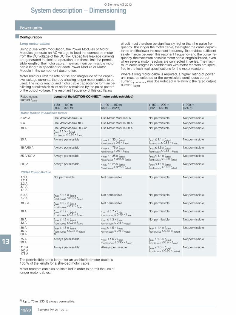
Long motor cables
Using pulse width modulation, the Power Modules or Motor Modules generate an AC voltage to feed the connected motor from the DC voltage of the DC link. Capacitive leakage currents are generated in clocked operation and these limit the permis-sible length of the motor cable. The maximum permissible motor cable length is specified for each Power Module or Motor Module in the component description.
Motor reactors limit the rate of rise and magnitude of the capaci-tive leakage currents, thereby allowing longer motor cables to be used. The motor reactor and motor cable capacitance form an os-cillating circuit which must not be stimulated by the pulse pattern of the output voltage. The resonant frequency of this oscillating
circuit must therefore be significantly higher than the pulse fre-quency. The longer the motor cable, the higher the cable capaci-tance and the lower the resonant frequency. To provide a sufficient safety margin between this resonant frequency and the pulse fre-quency, the maximum possible motor cable length is limited, even when several motor reactors are connected in series. The maxi-mum cable lengths in combination with motor reactors are speci-fied in the technical specifications for the motor reactors.
Where a long motor cable is required, a higher rating of power unit must be selected or the permissible continuous output current Icontinuous must be reduced in relation to the rated output current Irated.
The permissible cable length for an unshielded motor cable is 150 % of the length for a shielded motor cable.
Motor reactors can also be installed in order to permit the use of longer motor cables.
Rated output current Irated
Length of the MOTION-CONNECT motor cable (shielded)
> 50 … 100 m (164 … 328 ft)
> 100 … 150 m (328 … 492 ft)
> 150 … 200 m (492 … 656 ft)
> 200 m (656 ft)
Motor Module in booksize format
3 A/5 A Use Motor Module 9 A Use Motor Module 9 A Not permissible Not permissible
9 A Use Motor Module 18 A Use Motor Module 18 A Not permissible Not permissible
18 A Use Motor Module 30 A or Imax ≤ 1.5 × IratedIcontinuous ≤ 0.95 × Irated
Use Motor Module 30 A Not permissible Not permissible
30 A Always permissible I max ≤ 1.35 × IratedIcontinuous ≤ 0.9 × Irated
I max ≤ 1.1 × IratedIcontinuous ≤ 0.85 × Irated
Not permissible
45 A/60 A Always permissible I max ≤ 1.75 × IratedIcontinuous ≤ 0.9 × Irated
I max ≤ 1.5 × IratedIcontinuous ≤ 0.85 × Irated
Not permissible
85 A/132 A Always permissible I max ≤ 1.35 × IratedIcontinuous ≤ 0.95 × Irated
I max ≤ 1.1 × IratedIcontinuous ≤ 0.9 × Irated
Not permissible
200 A Always permissible I max ≤ 1.25 × IratedIcontinuous ≤ 0.95 × Irated
I max ≤ 1.1 × IratedIcontinuous ≤ 0.9 × Irated
Not permissible
PM340 Power Module
1.3 A1.7 A2.2 A3.1 A4.1 A
Not permissible Not permissible Not permissible Not permissible
5.9 A7.7 A
Imax ≤ 1.1 × IratedIcontinuous ≤ 0.6 × Irated
Not permissible Not permissible Not permissible
10.2 A Imax ≤ 1.2 × IratedIcontinuous ≤ 0.7 × Irated
Not permissible Not permissible Not permissible
18 A Imax ≤ 1.2 × IratedIcontinuous ≤ 0.7 × Irated
Imax ≤ 0.7 × IratedIcontinuous ≤ 0.45 × Irated
Not permissible Not permissible
25 A32 A
Imax ≤ 1.5 × IratedIcontinuous ≤ 0.9 × Irated
Imax ≤ 1.3 × IratedIcontinuous ≤ 0.8 × Irated
Not permissible Not permissible
38 A45 A60 A
Imax ≤ 1.6 × IratedIcontinuous ≤ 0.95 × Irated1)
Imax ≤ 1.5 × IratedIcontinuous ≤ 0.9 × Irated
Imax ≤ 1.4 × IratedIcontinuous ≤ 0.85 × Irated
Not permissible
75 A90 A
Always permissible Imax ≤ 1.6 × IratedIcontinuous ≤ 0.95 × Irated
Imax ≤ 1.5 × IratedIcontinuous ≤ 0.9 × Irated
Not permissible
110 A145 A178 A
Always permissible Always permissible Imax ≤ 1.5 × IratedIcontinuous ≤ 0.95 × Irated
Not permissible
1) Up to 70 m (230 ft) always permissible.
© Siemens AG 2013
System description — Dimensioning
Power units
13/21Siemens PM 21 · 2013
13
■ Configuration
Line Modules
In multi-axis drive applications, a number of Motor Modules are operated on a common DC link, which is supplied with power by a Line Module.
The first task is to decide whether a Basic Line Module, Smart Line Module or an Active Line Module will be used. On the one hand, this depends on whether the drive must be capable of regenerative feedback to the supply and, on the other hand, whether the power supply infeed is to be unregulated and there-fore dependent on the power supply voltage, or regulated to a constant DC link voltage.
The chassis format units are available in the 380 V to 480 V voltage range, but also include units in the 500 V to 690 V range. Basic Line Modules are designed for infeed operation only. Active Line Modules have regulated infeeds which feature a step-up function.
In order to calculate the required DC link power and select the correct Line Module, it is important to analyze the entire operat-ing sequence of the drive line-up connected to the DC link. Factors such as partial load, redundancies, duty cycles, coinci-dence factors and the operating mode (motor / generator mode) must be taken into account.
The DC link power Pd of a single Motor Module is calculated from the shaft output Pmech of the motor and the efficiency of the motor ηm and Motor Module ηwr.
The following applies in motor mode: Pd = Pmech / (ηm × hwr)
The following applies in generator mode: Pd = Pmech × hm × hwr
The motor and generator outputs must be added with the corresponding sign in order to calculate the total DC link power. For the power calculation, the DC link voltage Vd can be assumed to be constant. The required DC link current is there-fore calculated as Id = Pd/Vd
Basic Line Modules
The DC link voltage Vd of the Basic Line Modules is load-depen-dent. Under no-load conditions, the DC link is charged to the line voltage crest value VL, i.e. Vd = √2 × VL, e.g. Vd = 566 V when a 400 V supply system is connected.
Under load conditions, the DC link voltage reaches the average value of the rectified line voltage applied to the terminals. This average value is determined by the line voltage x factor 1.35. Owing to the voltage drop across the line reactor and in the line feeder cable, the DC link voltage under full load conditions is slightly lower than the theoretical value. In practice, the range of the DC link voltage Vd is as follows:
1.41 × VL > Vd > 1.32 × VL (no load → rated output)
Smart Line Modules
The DC link voltage Vd of Smart Line Modules is regulated to the average value of the rectified line voltage VL, i.e. Vd ≈ 1.35 × VL
Due to the voltage drop across the line reactor and in the line feeder cable, the DC link voltage decreases in motor operation and increases in generator operation. The DC link voltage Vd thus varies within the same range as on drives with a Basic Line Module:
1.41 × VL > Vd > 1.32 × VL (rated output generator → rated output motor)
Active Line Modules
The DC link voltage Vd is regulated to an adjustable value (Active Mode). An Active Line Module can also be switched to Smart Mode and then operates like a Smart Line Module. In Active Mode, the Active Line Module draws a virtually sinusoidal current from the supply system.
The rated infeed power of the Line Module refers to a line voltage of 380 V, 400 V or 690 V (690 V applies only to chassis format Line Modules). The output power of the Line Modules may be affected if they are operated on line voltages other than those stated above.
Depending on the ambient conditions (installation altitude, am-bient temperature), the rated infeed power of the Line Modules may need to be reduced (see chapter SINAMICS S120 drive system).
The coincidence factor takes into account the time characteristic of the torque for each individual axis.
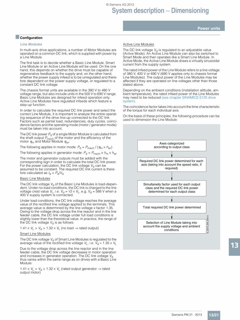
On the basis of these principles, the following procedure can be used to dimension the Line Module:
Required DC link power determined for each axis (taking into account the speed ratio, if
required)
Axes categorized according to output class
Simultaneity factor used for each output class and the required DC link power
determined for each output class
Total required DC link power determined
Selection of Line Module taking into account the supply voltage and ambient
conditions
G_D
212_
EN
_000
12
© Siemens AG 2013
System description — Dimensioning
Power units
13/22 Siemens PM 21 · 2013
13
■ Configuration
The following factors must also be taken into account when dimensioning the DC link:
Braking operation
As device losses are important in motor mode, the dimensioning for motor mode is also applicable to generator mode. With respect to motor braking operation, check that the energy fed back into the DC link does not exceed the permissible peak load capability of the Line Module.
In the case of higher regenerative outputs and to control the "line failure" operating scenario, a Braking Module must be provided, the Smart or Active Line Module must be overdimensioned or the regenerative output reduced by longer braking times.
For the configuration of the "EMERGENCY STOP" operating scenario, the Line Module must either be overdimensioned or an additional Braking Module must be used, in order that the DC link energy can be dissipated as quickly as possible.
Checking the DC link capacitance
During power-up, the Line Modules limit the charging current for the DC link capacitors. Due to the limits imposed by the pre-charging circuit, it is essential to observe the maximum permis-sible DC link capacitance values for the drive line-up specified in the technical specifications.
DC link pre-charging frequency
The pre-charging frequency of the DC link via a booksize format Line Module is calculated using the following formula:
For chassis format Line Modules, the maximum permissible DC link precharging interval is 3 minutes.
Special considerations for operation on Basic or Smart Line Module
Basic Line Modules and Smart Line Modules provide a lower DC link voltage than Active Line Modules. As a result, the following boundary conditions apply:• When operating asynchronous motors (induction motors), a
lower maximum motor power is available at high speeds at the same line voltage.
• On synchronous motors, a reduction in the dynamic drive characteristics must be expected at high speeds.
• On synchronous motors, the rated motor speed cannot be fully utilized when an overload capability is required.
Parallel connection of power units
Up to 4 Motor Modules or Line Modules in chassis format can be connected in parallel. Parallel connections can operate only in Vector Control mode.
Parallel connections may only include Motor Modules or Line Modules of the same type and with the same voltage and output ratings. Mixtures of different modules, e.g. Basic Line Modules and Active Line Modules, cannot be connected in parallel. The CU320-2, SIMOTION D4x5-2 or CX32-2 Control Unit can control only one drive object of type "Parallel connection Line Modules" and one of type "Parallel connection Motor Modules". It is assumed that all Line Modules or Motor Modules linked to the Control Unit are connected in parallel. A Control Unit can control, for example, the following components:• 1 Line Module + 2 parallel-connected Motor Modules• 2 parallel-connected Line Modules + 3 parallel-connected
Motor Modules
Combinations such as the following are not permissible: 2 Line Modules + 2 Motor Modules connected in parallel + 1 Motor Module
In order to ensure symmetrical current distribution among all parallel-connected modules, inductances must be provided for subsystem decoupling. However, the current compensatory control cannot completely prevent asymmetrical current distri-bution, which means that the following derating factors apply to parallel connections:
Number of precharges within 8 min DC-link capacitance of configured
drive line-up in μF
Max. permissible DC link capacitance infeed module in μF =
Designation Derating factor for parallel connection of 2 to 4 Modules
Max. permissible number of parallel-connected Modules
Active Line Modules 0.95 4
Basic Line Modules 0.925 4
Motor Modules 0.95 4
© Siemens AG 2013
System description — Dimensioning
Power units
13/23Siemens PM 21 · 2013
13
■ Configuration
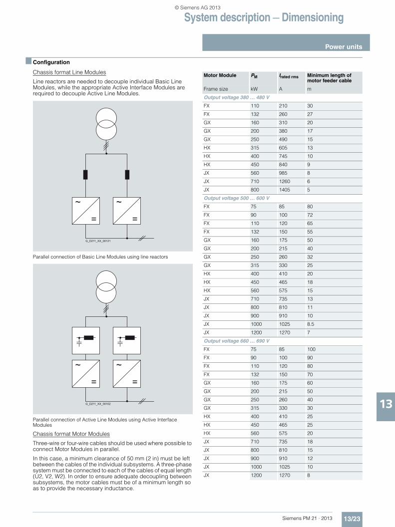
Chassis format Line Modules
Line reactors are needed to decouple individual Basic Line Modules, while the appropriate Active Interface Modules are required to decouple Active Line Modules.
Parallel connection of Basic Line Modules using line reactors
Parallel connection of Active Line Modules using Active Interface Modules
Chassis format Motor Modules
Three-wire or four-wire cables should be used where possible to connect Motor Modules in parallel.
In this case, a minimum clearance of 50 mm (2 in) must be left between the cables of the individual subsystems. A three-phase system must be connected to each of the cables of equal length (U2, V2, W2). In order to ensure adequate decoupling between subsystems, the motor cables must be of a minimum length so as to provide the necessary inductance.
=
~
=
~
G_D21 1_XX_00121
=
~
=
~
G_D2 1 1_XX_00102
Motor Module PM Irated rms Minimum length of motor feeder cable
Frame size kW A m
Output voltage 380 … 480 V
FX 110 210 30
FX 132 260 27
GX 160 310 20
GX 200 380 17
GX 250 490 15
HX 315 605 13
HX 400 745 10
HX 450 840 9
JX 560 985 8
JX 710 1260 6
JX 800 1405 5
Output voltage 500 … 600 V
FX 75 85 80
FX 90 100 72
FX 110 120 65
FX 132 150 55
GX 160 175 50
GX 200 215 40
GX 250 260 32
GX 315 330 25
HX 400 410 20
HX 450 465 18
HX 560 575 15
JX 710 735 13
JX 800 810 11
JX 900 910 10
JX 1000 1025 8.5
JX 1200 1270 7
Output voltage 660 … 690 V
FX 75 85 100
FX 90 100 90
FX 110 120 80
FX 132 150 70
GX 160 175 60
GX 200 215 50
GX 250 260 40
GX 315 330 30
HX 400 410 25
HX 450 465 25
HX 560 575 20
JX 710 735 18
JX 800 810 15
JX 900 910 12
JX 1000 1025 10
JX 1200 1270 8
© Siemens AG 2013
System description — Dimensioning
Power units
13/24 Siemens PM 21 · 2013
13
■ Configuration
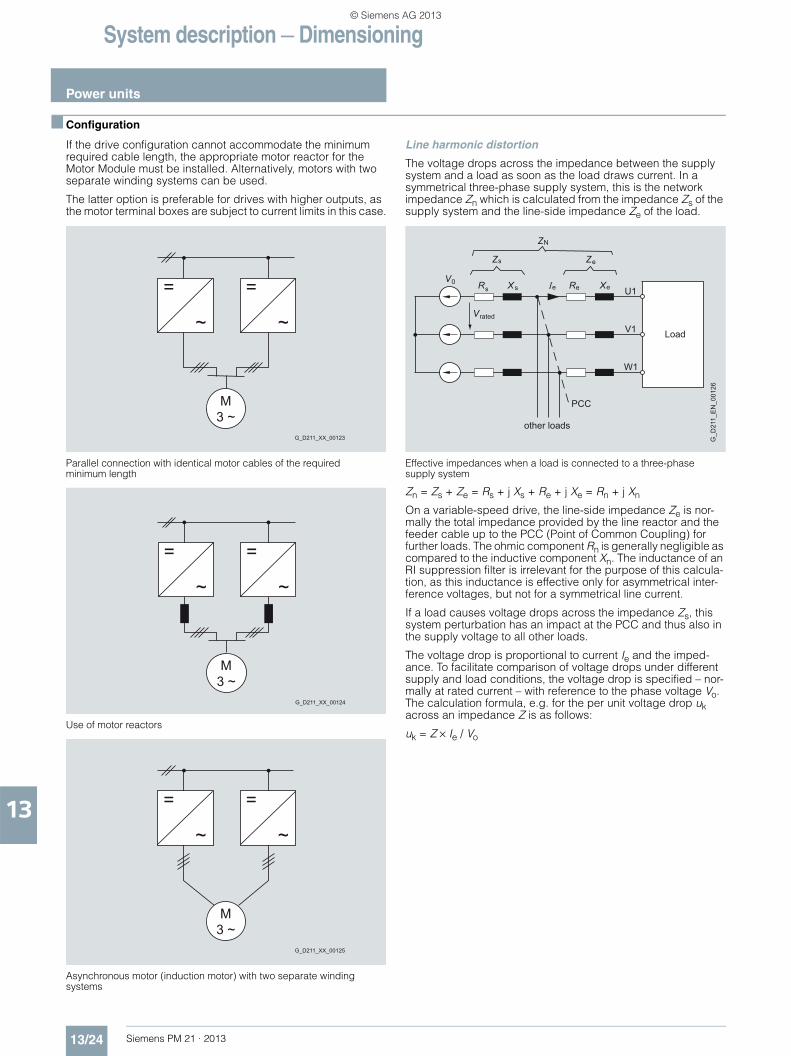
If the drive configuration cannot accommodate the minimum required cable length, the appropriate motor reactor for the Motor Module must be installed. Alternatively, motors with two separate winding systems can be used.
The latter option is preferable for drives with higher outputs, as the motor terminal boxes are subject to current limits in this case.
Parallel connection with identical motor cables of the required minimum length
Use of motor reactors
Asynchronous motor (induction motor) with two separate winding systems
Line harmonic distortion
The voltage drops across the impedance between the supply system and a load as soon as the load draws current. In a symmetrical three-phase supply system, this is the network impedance Zn which is calculated from the impedance Zs of the supply system and the line-side impedance Ze of the load.
Effective impedances when a load is connected to a three-phase supply system
Zn = Zs + Ze = Rs + j Xs + Re + j Xe = Rn + j Xn
On a variable-speed drive, the line-side impedance Ze is nor-mally the total impedance provided by the line reactor and the feeder cable up to the PCC (Point of Common Coupling) for further loads. The ohmic component Rn is generally negligible as compared to the inductive component Xn. The inductance of an RI suppression filter is irrelevant for the purpose of this calcula-tion, as this inductance is effective only for asymmetrical inter-ference voltages, but not for a symmetrical line current.
If a load causes voltage drops across the impedance Zs, this system perturbation has an impact at the PCC and thus also in the supply voltage to all other loads.
The voltage drop is proportional to current Ie and the imped-ance. To facilitate comparison of voltage drops under different supply and load conditions, the voltage drop is specified – nor-mally at rated current – with reference to the phase voltage Vo. The calculation formula, e.g. for the per unit voltage drop uk across an impedance Z is as follows:
uk = Z × Ie / Vo
=
~
=
~
M 3 ~
G_D2 1 1_XX_00123
=
~
=
~
M 3 ~
G_D2 1 1_XX_00124
=
~
=
~
M 3 ~
G_D211_XX_00125
Load
U1
V1
W1
PCC
VR X R X
Z Z
other loads
0s s e e e
es
ZN
Vrated
G_D
211_
EN
_001
26
© Siemens AG 2013
System description — Dimensioning
Power units
13/25Siemens PM 21 · 2013
13
■ Configuration
Example 1:
A Power Module with rated line current Ie is directly connected to a low-voltage transformer and the PCC is the transformer con-nection terminal. The equation for the ratio between rated line current Ie of the Power Module and rated current Irated of the transformer is Ie = 0.25 × Irated. The per unit voltage drop uk of the 400 V transformer is 4 %. If the transformer is loaded with its rated current Irated, the voltage drop across impedance Zs is 9.2 V (corresponding to 4 % of the phase voltage Vo = 230 V).
uk = (Zs × Irated) / 230 V = 0.04
The following formula applies to the rated line current Ie of the Power Module: Ie = k × Irated
The per unit voltage drop across the transformer when loaded with Ie is thus: uk = Zs × Ie / Vo = Zs × k × Irated / Vo
With the specified ratio between Ie and Irated, the per unit voltage drop is calculated as uk = 1 % or 2.3 V. In relation to the Power Module, this transformer therefore functions like a line impedance in accordance with uk = 1 %.
The magnitude of system perturbation in converter systems is assessed on the basis of short-circuit power ratio Rsc:
Rsc = Scν / P
According to this definition in accordance with EN 60146-1, P is the fundamental-wave apparent power drawn by the converter.Scν is the short-circuit power drawn from the mains in the event of a short-circuit on the terminals U1, V1, W1. Since the ohmic components of impedances are negligible in practice, the following applies Zn ≈ j Xn
Scν ≈ 3 × Vo2 / Xn
and thus Rsc ≈ 3 × Vo2 / (Xn × P)
The short-circuit power ratio Rsc is therefore dependent on the current output power P of the converter and is determined by network impedance Xn.
If we assume the power to be P ≈ 3 × Vo × Ie = √3 × Vrated × Iethe short-circuit power ratio Rsc is in inverse proportion to the per unit voltage drop uk across the effective line impedance.
Rsc ≈ 3 × Vo2 / (Xn × P) = 3 × Vo
2 / (Xn × 3 × Vo × Ie) =Vo / (Xn × Ie) = 1 / uk
The short-circuit power ratio for example 1 is Rsc ≈ 100 if no line reactor is installed (Ze = 0).
Note:
The term "short-circuit power ratio" as used in technical stan-dards is not a harmonized definition. The short-circuit power ratio Rsce defined according to IEC 61000-3-12 is calculated from the short-circuit power SSC at the PCC referred to the power Sequ = 3 × Vo × Ie consumed by the load.
Basic Line Modules and Power Modules are designed with a rectifier bridge on the line side. An inherent feature of the princi-ple of rectification with load-side capacitance for DC link voltage smoothing are harmonics in the line current which result in a non-sinusoidal power input. The diagram shows the basic current waveform of a Power Module or Basic Line Module as a function of short-circuit power ratio Rsc.
Active Line Modules generate virtually no current harmonics (Active Mode) at all and are employed when system perturbation needs to be minimized, e.g. stipulation of IEEE 519 that THD (Total Harmonic Distortion) must be < 10 %.
The SIZER for Siemens Drives engineering tool calculates the line harmonic distortion on the basis of the supply data entered and lists them against the limit values of relevant standards.
Line current of a Basic Line Module or Power Module as a function of the short-circuit power ratio Rsc
The rms of the line current Ie for which the line-side components must be rated comprises fundamental wave Ie1 and the current harmonics, which increase in relation to the rise in short-circuit power ratio Rsc. If the DC link power Pd has been calculated (see Line Modules), the required line-side active power is a known quantity with Line Module efficiency, or the rectifier efficiency in the case of a Power Module. However, this active power is connected only with the current fundamental wave Ie1. The rms of the line current Ie is always greater than Ie1 as a result of the current harmonics. The following applies to a short-circuit power ratio Rsc = 100:
Ie ≈ 1.3 × Ie1
The apparent power of a transformer selected to supply the drive must be greater than the drive power by a factor of about 1.3.
The harmonic currents produce only alternating power, but no active power. The following applies to the apparent power S on the line side:
S2 = P2 + Q12 + D2
• with active componentP = 3 × Vo × I1 × cos ϕ1 produced solely by the current fundamental wave
• and reactive componentQ1 = 3 × Vo × I1 × sin ϕ1
• and the distortion component
The ratio between active power and apparent power is referred to as total power factor λ :
e
e
G_D
211_
EN
_001
27a
sc R = approx. 100
sc R = approx. 10
V
0V
0
D 3 V= 0=2
2
= =P PS P 2 2 2
1+ D+Q
© Siemens AG 2013
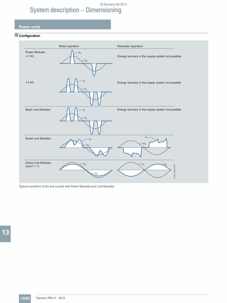
System description — Dimensioning
Power units
13/26 Siemens PM 21 · 2013
13
■ Configuration
Typical waveform of the line current with Power Modules and Line Modules
e
e
e
e
e
e
e
G_D
211_
EN
_001
30
Motor operation
Power Modules
Basic Line Modules
Smart Line Modules
Active Line Modules(cos = 1)
1 AC
Generator operation
Energy recovery in the supply system not possible
3 AC Energy recovery in the supply system not possible
Energy recovery in the supply system not possible
0V
0V
0V
0V
0V 0V
0V
© Siemens AG 2013
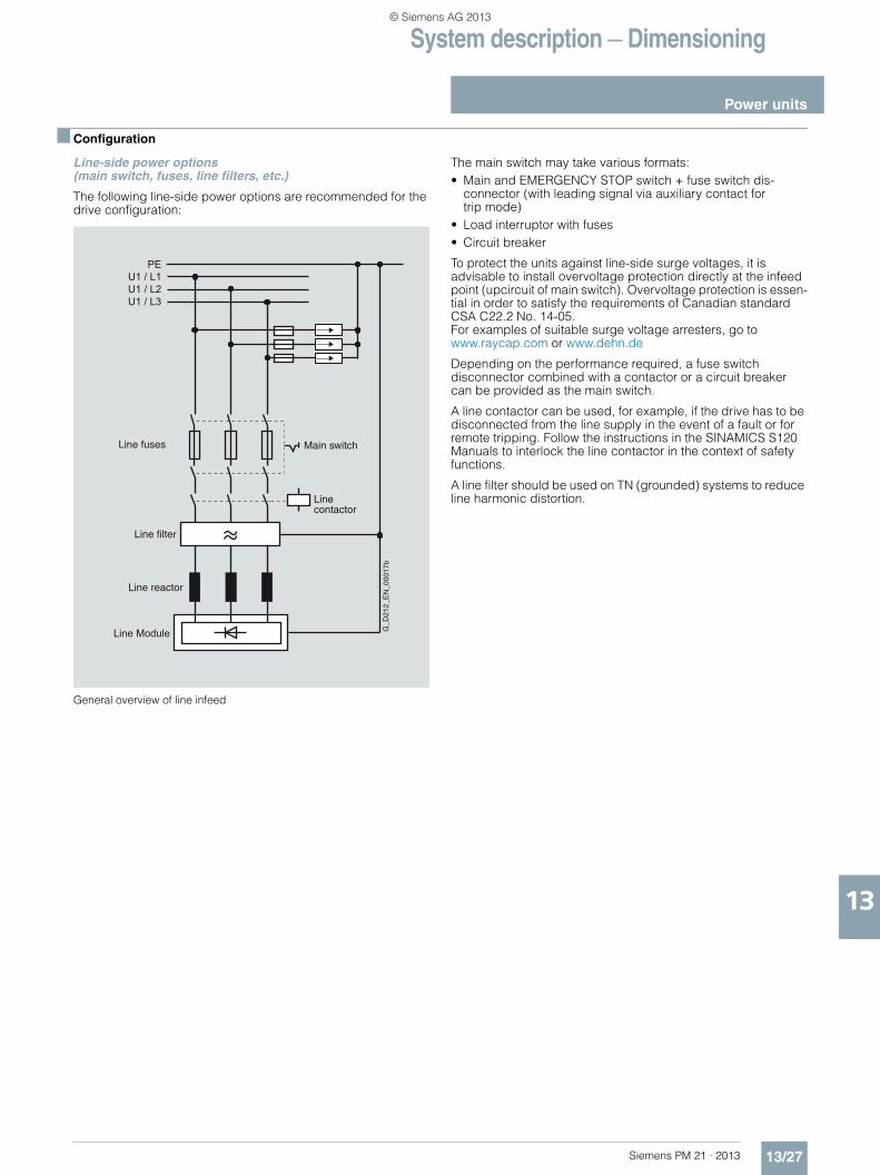
System description — Dimensioning
Power units
13/27Siemens PM 21 · 2013
13
■ Configuration
Line-side power options (main switch, fuses, line filters, etc.)
The following line-side power options are recommended for the drive configuration:
General overview of line infeed
The main switch may take various formats:• Main and EMERGENCY STOP switch + fuse switch dis-
connector (with leading signal via auxiliary contact for trip mode)
• Load interruptor with fuses• Circuit breaker
To protect the units against line-side surge voltages, it is advisable to install overvoltage protection directly at the infeed point (upcircuit of main switch). Overvoltage protection is essen-tial in order to satisfy the requirements of Canadian standard CSA C22.2 No. 14-05. For examples of suitable surge voltage arresters, go to www.raycap.com or www.dehn.de
Depending on the performance required, a fuse switch disconnector combined with a contactor or a circuit breaker can be provided as the main switch.
A line contactor can be used, for example, if the drive has to be disconnected from the line supply in the event of a fault or for remote tripping. Follow the instructions in the SINAMICS S120 Manuals to interlock the line contactor in the context of safety functions.
A line filter should be used on TN (grounded) systems to reduce line harmonic distortion.
PEU1 / L1U1 / L2U1 / L3
Line Module
Line fuses Main switch
Linecontactor
Line filter
Line reactor
G_D
212_
EN
_000
17b
© Siemens AG 2013
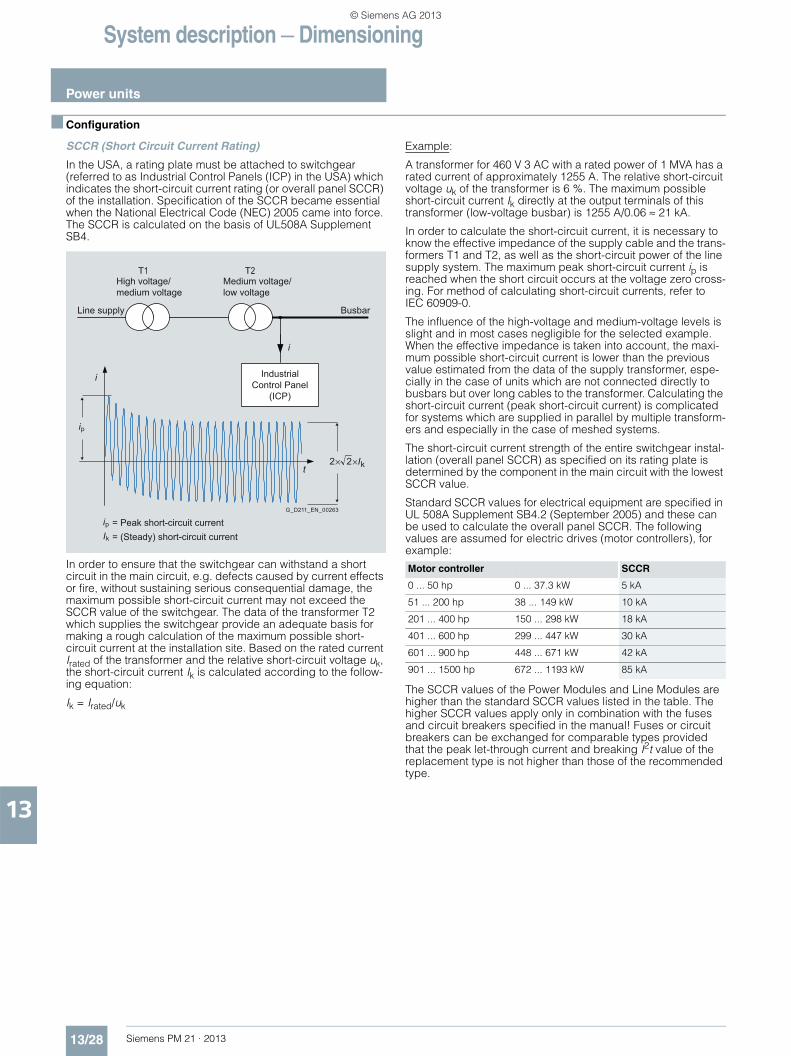
System description — Dimensioning
Power units
13/28 Siemens PM 21 · 2013
13
■ Configuration
SCCR (Short Circuit Current Rating)
In the USA, a rating plate must be attached to switchgear (referred to as Industrial Control Panels (ICP) in the USA) which indicates the short-circuit current rating (or overall panel SCCR) of the installation. Specification of the SCCR became essential when the National Electrical Code (NEC) 2005 came into force. The SCCR is calculated on the basis of UL508A Supplement SB4.
In order to ensure that the switchgear can withstand a short circuit in the main circuit, e.g. defects caused by current effects or fire, without sustaining serious consequential damage, the maximum possible short-circuit current may not exceed the SCCR value of the switchgear. The data of the transformer T2 which supplies the switchgear provide an adequate basis for making a rough calculation of the maximum possible short-circuit current at the installation site. Based on the rated current Irated of the transformer and the relative short-circuit voltage uk, the short-circuit current Ik is calculated according to the follow-ing equation:
Ik = Irated/uk
Example:
A transformer for 460 V 3 AC with a rated power of 1 MVA has a rated current of approximately 1255 A. The relative short-circuit voltage uk of the transformer is 6 %. The maximum possible short-circuit current Ik directly at the output terminals of this transformer (low-voltage busbar) is 1255 A/0.06 ≈ 21 kA.
In order to calculate the short-circuit current, it is necessary to know the effective impedance of the supply cable and the trans-formers T1 and T2, as well as the short-circuit power of the line supply system. The maximum peak short-circuit current ip is reached when the short circuit occurs at the voltage zero cross-ing. For method of calculating short-circuit currents, refer to IEC 60909-0.
The influence of the high-voltage and medium-voltage levels is slight and in most cases negligible for the selected example. When the effective impedance is taken into account, the maxi-mum possible short-circuit current is lower than the previous value estimated from the data of the supply transformer, espe-cially in the case of units which are not connected directly to busbars but over long cables to the transformer. Calculating the short-circuit current (peak short-circuit current) is complicated for systems which are supplied in parallel by multiple transform-ers and especially in the case of meshed systems.
The short-circuit current strength of the entire switchgear instal-lation (overall panel SCCR) as specified on its rating plate is determined by the component in the main circuit with the lowest SCCR value.
Standard SCCR values for electrical equipment are specified in UL 508A Supplement SB4.2 (September 2005) and these can be used to calculate the overall panel SCCR. The following values are assumed for electric drives (motor controllers), for example:
The SCCR values of the Power Modules and Line Modules are higher than the standard SCCR values listed in the table. The higher SCCR values apply only in combination with the fuses and circuit breakers specified in the manual! Fuses or circuit breakers can be exchanged for comparable types provided that the peak let-through current and breaking I2t value of the replacement type is not higher than those of the recommended type.
ip
ipIk
2 2 Ikt
i
Busbar
= Peak short-circuit current= (Steady) short-circuit current
Line supply
i
Industrial Control Panel
(ICP)
Medium voltage/low voltage
2THigh voltage/medium voltage
1T
G_D211_EN_00263
Motor controller SCCR
0 ... 50 hp 0 ... 37.3 kW 5 kA
51 ... 200 hp 38 ... 149 kW 10 kA
201 ... 400 hp 150 ... 298 kW 18 kA
401 ... 600 hp 299 ... 447 kW 30 kA
601 ... 900 hp 448 ... 671 kW 42 kA
901 ... 1500 hp 672 ... 1193 kW 85 kA
© Siemens AG 2013
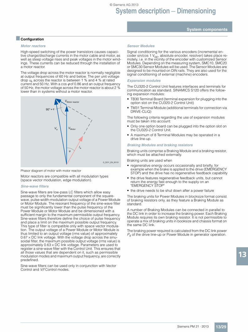
System description — Dimensioning
System components
13/29Siemens PM 21 · 2013
13
■ Configuration
Motor reactors
High-speed switching of the power transistors causes capaci-tive charge/discharge currents in the motor cable and motor, as well as steep voltage rises and peak voltages in the motor wind-ings. These currents can be reduced through the installation of a motor reactor.
The voltage drop across the motor reactor is normally negligible at output frequencies of 60 Hz and below. The per unit voltage drop uk across the reactor is between 1 % and 4 % at rated current and 50 Hz. With a cos ϕ of 0.86 and an output frequency of 50 Hz, the motor voltage across the motor reactor is about 2 % lower than in systems without a motor reactor.
Phasor diagram of motor with motor reactor
Motor reactors are compatible with all modulation types (space vector modulation, edge modulation).
Sine-wave filters
Sine-wave filters are low-pass LC filters which allow easy passage to only the fundamental component of the square-wave, pulse-width-modulation output voltage of a Power Module or Motor Module. The resonant frequency of the sine-wave filter must be significantly lower than the pulse frequency of the Power Module or Motor Module and be dimensioned with a sufficient margin to the maximum permissible output frequency. Sine-wave filters therefore define the choice of pulse frequency and place a limit on the maximum possible output frequency. This type of filter is compatible only with space vector modula-tion. The output voltage of a Power Module or Motor Module is thus limited to an output voltage (rms value) of approximately 0.67 × DC link voltage. With the voltage drop across the sinu-soidal filter, the maximum possible output voltage (rms value) is approximately 0.63 × DC link voltage. Parameters are used to register a sine-wave filter with the Control Unit. This ensures that all those values that are dependent on it, such as permissible modulation modes and maximum output frequency, are correctly predefined.
Sine-wave filters can be used only in conjunction with Vector Control and V/f Control modes.
Sensor Modules
Signal conditioning for the various encoders (incremental en-coder sin/cos 1 Vpp, absolute encoder, resolver) takes place re-motely, i.e. in the vicinity of the encoder with customized Sensor Modules. Depending on the measuring system, SMC10, SMC20 or SMC30 Sensor Modules will be used. The Sensor Modules are designed to be mounted on DIN rails. They are also used for the signal conditioning of external (machine) encoders.
Expansion modules
The CU320-2 Control Unit features interfaces and terminals for communication as standard. SINAMICS S120 offers the follow-ing expansion modules:• TB30 Terminal Board (terminal expansion for plugging into the
option slot on the CU320-2 Control Unit)• TM31 Terminal Module (additional terminals for connection via
DRIVE-CLiQ)
The following criteria regarding the use of expansion modules must be taken into account:• Only one option board can be plugged into the option slot on
the CU320-2 Control Unit.• A maximum of 8 Terminal Modules may be operated in a
drive line-up.
Braking Modules and braking resistors
Braking units comprise a Braking Module and a braking resistor, which must be attached externally.
Braking units are used when• regenerative energy occurs occasionally and briefly, for
example when the brake is applied to the drive (EMERGENCY STOP) and the drive has no regenerative feedback capability
• the drive features regenerative feedback units, but cannot return the energy fast enough to the supply on an "EMERGENCY STOP"
• the drive needs to be shut down after a power failure
The braking units for Power Modules in blocksize format consist of braking resistors only, as they feature a Braking Module as standard.
A number of Braking Modules can be connected in parallel to the DC link in order to increase the braking power. Each Braking Module requires its own braking resistor. It is not permissible to operate a mix of braking units in booksize and chassis format on the same DC link.
The braking power required is calculated from the DC link power Pd of the drive line-up or Power Module in generator operation.
Motor reactorV
G_D211_EN_00131
MotorVaV
90°+
Ia
© Siemens AG 2013
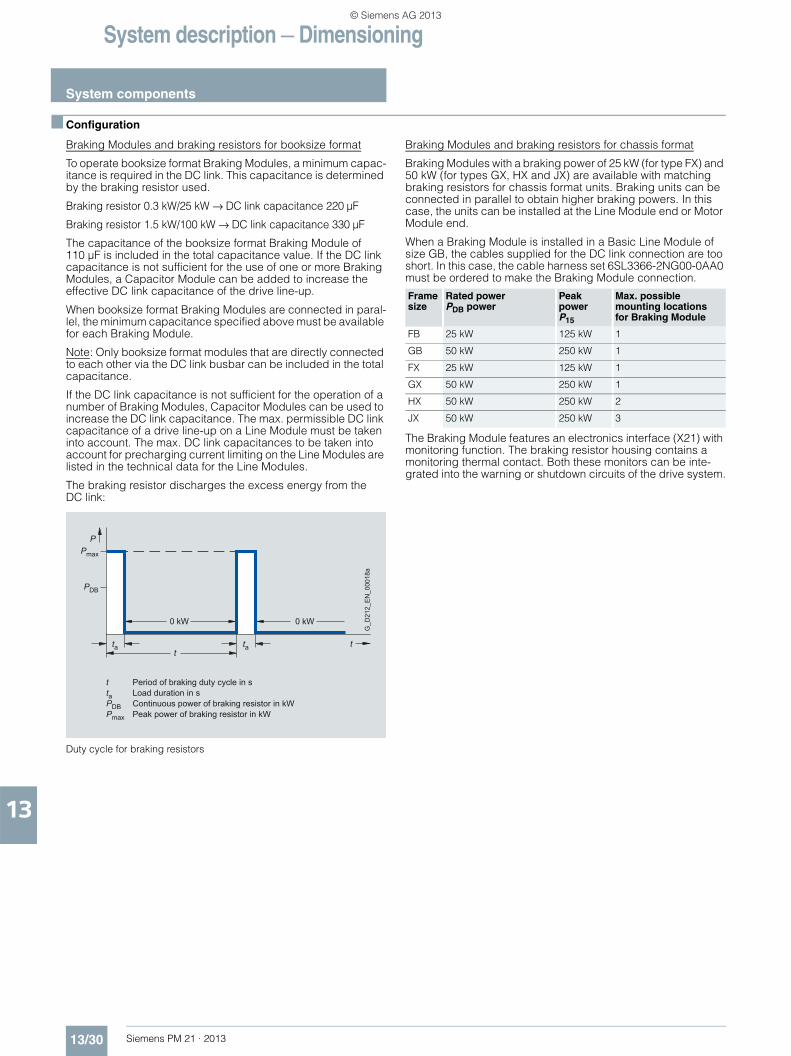
System description — Dimensioning
System components
13/30 Siemens PM 21 · 2013
13
■ Configuration
Braking Modules and braking resistors for booksize format
To operate booksize format Braking Modules, a minimum capac-itance is required in the DC link. This capacitance is determined by the braking resistor used.
Braking resistor 0.3 kW/25 kW → DC link capacitance 220 µF
Braking resistor 1.5 kW/100 kW → DC link capacitance 330 µF
The capacitance of the booksize format Braking Module of 110 µF is included in the total capacitance value. If the DC link capacitance is not sufficient for the use of one or more Braking Modules, a Capacitor Module can be added to increase the effective DC link capacitance of the drive line-up.
When booksize format Braking Modules are connected in paral-lel, the minimum capacitance specified above must be available for each Braking Module.
Note: Only booksize format modules that are directly connected to each other via the DC link busbar can be included in the total capacitance.
If the DC link capacitance is not sufficient for the operation of a number of Braking Modules, Capacitor Modules can be used to increase the DC link capacitance. The max. permissible DC link capacitance of a drive line-up on a Line Module must be taken into account. The max. DC link capacitances to be taken into account for precharging current limiting on the Line Modules are listed in the technical data for the Line Modules.
The braking resistor discharges the excess energy from the DC link:
Duty cycle for braking resistors
Braking Modules and braking resistors for chassis format
Braking Modules with a braking power of 25 kW (for type FX) and 50 kW (for types GX, HX and JX) are available with matching braking resistors for chassis format units. Braking units can be connected in parallel to obtain higher braking powers. In this case, the units can be installed at the Line Module end or Motor Module end.
When a Braking Module is installed in a Basic Line Module of size GB, the cables supplied for the DC link connection are too short. In this case, the cable harness set 6SL3366-2NG00-0AA0 must be ordered to make the Braking Module connection.
The Braking Module features an electronics interface (X21) with monitoring function. The braking resistor housing contains a monitoring thermal contact. Both these monitors can be inte-grated into the warning or shutdown circuits of the drive system.
Pmax
P
0 kW
t
0 kW
tat
ta
t Period of braking duty cycle in sta Load duration in sPDB Continuous power of braking resistor in kWPmax Peak power of braking resistor in kW
G_D
212_
EN_0
0018
a
PDB
Frame size
Rated power PDB power
Peak power P15
Max. possible mounting locations for Braking Module
FB 25 kW 125 kW 1
GB 50 kW 250 kW 1
FX 25 kW 125 kW 1
GX 50 kW 250 kW 1
HX 50 kW 250 kW 2
JX 50 kW 250 kW 3
© Siemens AG 2013

System description — Dimensioning
System components
13/31Siemens PM 21 · 2013
13
■ Configuration
Calculation of Braking Module and braking resistorrequirements• For periodic duty cycles with a cycle duration of ≤ 90 s, the
average value of the braking power within this duty cycle must be defined. The relevant cycle duration must be applied as the time base.
• For periodic duty cycles with a cycle duration of ≥ 90 s or for sporadic braking operations, a time interval of 90 s in which the highest average value occurs must be selected. The 90 s period must be applied as the time base.
Apart from the average braking power, the required peak braking power must also be taken into account when braking units are selected (Braking Module and braking resistor).
Basic data
Load diagram
Braking resistors for Power Modules in blocksize format
The braking resistors for the FSA and FSB frame sizes are de-signed as substructure components. Braking resistors for frame sizes FSC to FSF should be mounted outside the control cabinet owing to their high heat losses.
The Control Unit monitors the pulse/pause ratio (ON time/OFF time) of the braking resistor and shuts it down on faults if it calculates that the resistor is at risk of overheating.
Braking resistors feature a temperature switch with NC contacts that open when the permissible temperature is exceeded. The temperature switch must be evaluated to prevent consequential damage if the braking resistor overheats.
The braking power Pmech on the motor shaft is higher than the power loss of the braking resistor as this need only convert the DC link energy into heat.
The DC link power Pd of the Power Module in generator mode is calculated from the shaft power Pmech of the motor and the power loss in the motor Pv motor and in the Power Module Pv Power Module as:
Pd = Pmech – Pv motor – Pv Power Module = Pbraking resistor
The power losses can be estimated from the efficiency values of the motor ηm and Power Module ηwr:
Pbraking resistor = Pd = Pmech × ηm × ηwr
Capacitor Module in booksize format
The Capacitor Module functions as a short-term energy buffer, e.g. for bridging brief power failures or for storing braking energy. The buffered energy W can be calculated with the following formula:
W = ½ × C × (Vd12 – Vd2
2)
C = effective capacity of Capacitor Module 4 mF
Vd1 = DC link voltage when buffering starts
Vd2 = DC link voltage when buffering ends
Example:
Vd1 = 600 V; Vd2 = 430 V
The resultant energy calculation is W = 350 Ws
With this energy, for example, it is possible to buffer a Motor Module with 3 kW load for about 100 ms.
Control Supply Module in booksize format
The Control Supply Module provides a 24 V DC power supply via the line or DC link, in order to maintain the electronics power supply for the components in the event of a line failure. This makes it possible, for example, to make emergency retraction movements in the event of the failure of the line supply.
Line voltage
Power range Motor Modules
Braking ModuleContin-uous power PDB
Braking Module Power P40
Braking Module Power P20
Braking Module Peak power P15
380 … 480 V 110 … 132 kW 25 kW 50 kW 100 kW 125 kW
160 … 800 kW 50 kW 100 kW 200 kW 250 kW
660 … 690 V 75 … 132 kW 25 kW 50 kW 100 kW 125 kW
160 … 1200 kW 50 kW 100 kW 200 kW 250 kW
15P
20P
40P
15P20P40P
15 s 100908070605040302010 t
G_D211_EN_00013b
= Rated power
DB
DB
DB
= 5 x P = Power which is permissible every 90 s for 15 s= 4 x P = Power which is permissible every 90 s for 20 s= 2 x P = Power which is permissible every 90 s for 40 s
DB
PDB
P/PDB
1.25
1.50
0.25
0
0.50
0.75
1.00
P
© Siemens AG 2013
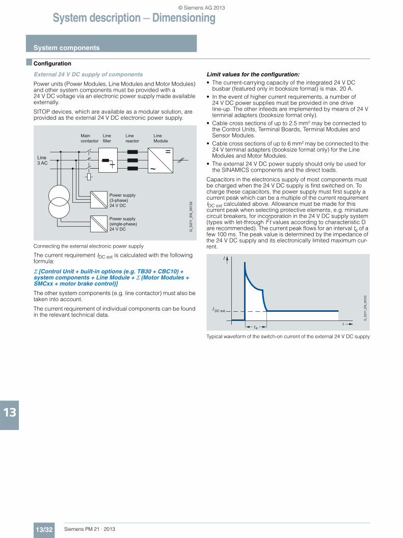
System description — Dimensioning
System components
13/32 Siemens PM 21 · 2013
13
■ Configuration
External 24 V DC supply of components
Power units (Power Modules, Line Modules and Motor Modules) and other system components must be provided with a 24 V DC voltage via an electronic power supply made available externally.
SITOP devices, which are available as a modular solution, are provided as the external 24 V DC electronic power supply.
Connecting the external electronic power supply
The current requirement IDC ext is calculated with the following formula:
Σ [Control Unit + built-in options (e.g. TB30 + CBC10) + system components + Line Module + Σ (Motor Modules + SMCxx + motor brake control)]
The other system components (e.g. line contactor) must also be taken into account.
The current requirement of individual components can be found in the relevant technical data.
Limit values for the configuration: • The current-carrying capacity of the integrated 24 V DC
busbar (featured only in booksize format) is max. 20 A.• In the event of higher current requirements, a number of
24 V DC power supplies must be provided in one drive line-up. The other infeeds are implemented by means of 24 V terminal adapters (booksize format only).
• Cable cross sections of up to 2.5 mm² may be connected to the Control Units, Terminal Boards, Terminal Modules and Sensor Modules.
• Cable cross sections of up to 6 mm² may be connected to the 24 V terminal adapters (booksize format only) for the Line Modules and Motor Modules.
• The external 24 V DC power supply should only be used for the SINAMICS components and the direct loads.
Capacitors in the electronics supply of most components must be charged when the 24 V DC supply is first switched on. To charge these capacitors, the power supply must first supply a current peak which can be a multiple of the current requirement IDC ext calculated above. Allowance must be made for this current peak when selecting protective elements, e.g. miniature circuit breakers, for incorporation in the 24 V DC supply system (types with let-through I2t values according to characteristic D are recommended). The current peak flows for an interval te of a few 100 ms. The peak value is determined by the impedance of the 24 V DC supply and its electronically limited maximum cur-rent.
Typical waveform of the switch-on current of the external 24 V DC supply
=
~Line3 AC
Power supply(3-phase)24 V DC
Power supply(single-phase)24 V DC
Maincontactor
Linefilter
Linereactor
LineModule
G_D
211_
EN
_001
32
G_D
211_
EN
_001
33
I
DC extI
tte
© Siemens AG 2013
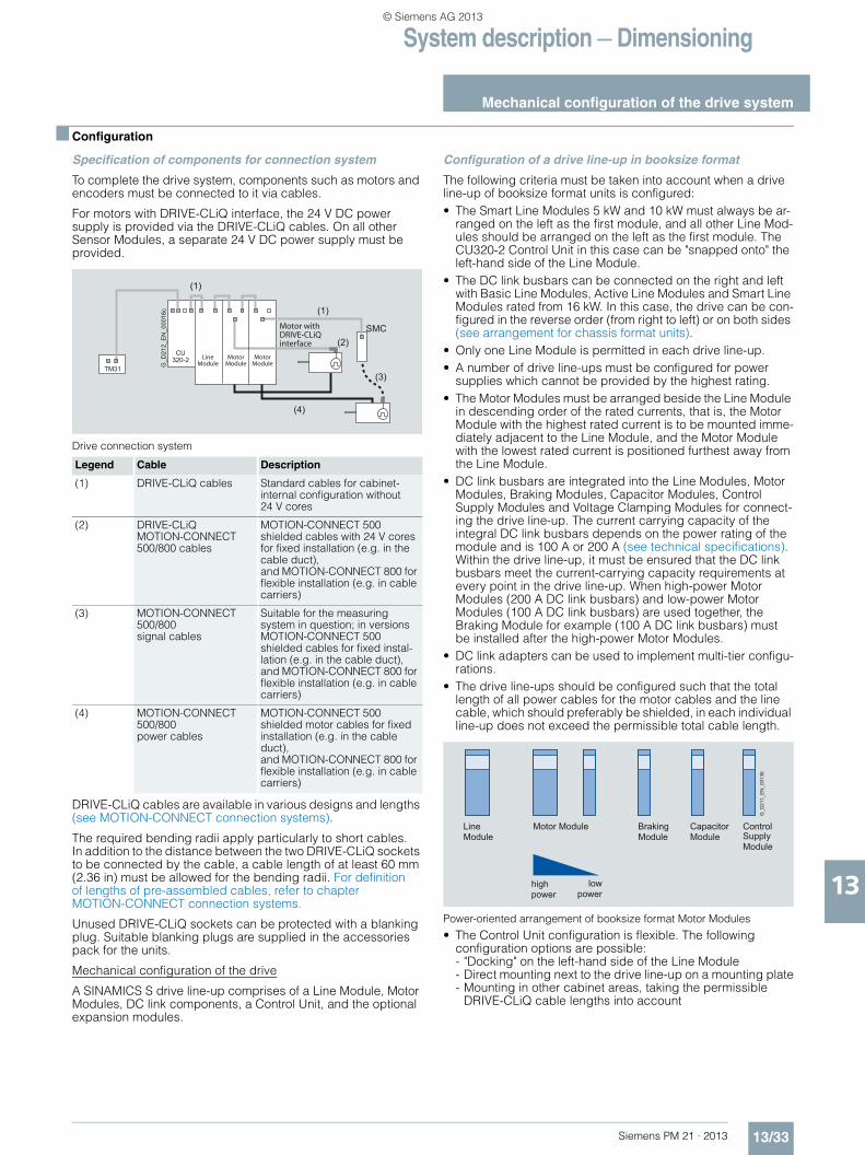
System description — Dimensioning
Mechanical configuration of the drive system
13/33Siemens PM 21 · 2013
13
■ Configuration
Specification of components for connection system
To complete the drive system, components such as motors and encoders must be connected to it via cables.
For motors with DRIVE-CLiQ interface, the 24 V DC power supply is provided via the DRIVE-CLiQ cables. On all other Sensor Modules, a separate 24 V DC power supply must be provided.
Drive connection system
DRIVE-CLiQ cables are available in various designs and lengths (see MOTION-CONNECT connection systems).
The required bending radii apply particularly to short cables. In addition to the distance between the two DRIVE-CLiQ sockets to be connected by the cable, a cable length of at least 60 mm (2.36 in) must be allowed for the bending radii. For definition of lengths of pre-assembled cables, refer to chapter MOTION-CONNECT connection systems.
Unused DRIVE-CLiQ sockets can be protected with a blanking plug. Suitable blanking plugs are supplied in the accessories pack for the units.
Mechanical configuration of the drive
A SINAMICS S drive line-up comprises of a Line Module, Motor Modules, DC link components, a Control Unit, and the optional expansion modules.
Configuration of a drive line-up in booksize format
The following criteria must be taken into account when a drive line-up of booksize format units is configured:• The Smart Line Modules 5 kW and 10 kW must always be ar-
ranged on the left as the first module, and all other Line Mod-ules should be arranged on the left as the first module. The CU320-2 Control Unit in this case can be "snapped onto" the left-hand side of the Line Module.
• The DC link busbars can be connected on the right and left with Basic Line Modules, Active Line Modules and Smart Line Modules rated from 16 kW. In this case, the drive can be con-figured in the reverse order (from right to left) or on both sides (see arrangement for chassis format units).
• Only one Line Module is permitted in each drive line-up.• A number of drive line-ups must be configured for power
supplies which cannot be provided by the highest rating.• The Motor Modules must be arranged beside the Line Module
in descending order of the rated currents, that is, the Motor Module with the highest rated current is to be mounted imme-diately adjacent to the Line Module, and the Motor Module with the lowest rated current is positioned furthest away from the Line Module.
• DC link busbars are integrated into the Line Modules, Motor Modules, Braking Modules, Capacitor Modules, Control Supply Modules and Voltage Clamping Modules for connect-ing the drive line-up. The current carrying capacity of the integral DC link busbars depends on the power rating of the module and is 100 A or 200 A (see technical specifications). Within the drive line-up, it must be ensured that the DC link busbars meet the current-carrying capacity requirements at every point in the drive line-up. When high-power Motor Modules (200 A DC link busbars) and low-power Motor Modules (100 A DC link busbars) are used together, the Braking Module for example (100 A DC link busbars) must be installed after the high-power Motor Modules.
• DC link adapters can be used to implement multi-tier configu-rations.
• The drive line-ups should be configured such that the total length of all power cables for the motor cables and the line cable, which should preferably be shielded, in each individual line-up does not exceed the permissible total cable length.
Power-oriented arrangement of booksize format Motor Modules
• The Control Unit configuration is flexible. The following configuration options are possible: - "Docking" on the left-hand side of the Line Module- Direct mounting next to the drive line-up on a mounting plate- Mounting in other cabinet areas, taking the permissible
DRIVE-CLiQ cable lengths into account
Legend Cable Description
(1) DRIVE-CLiQ cables Standard cables for cabinet-internal configuration without 24 V cores
(2) DRIVE-CLiQ MOTION-CONNECT 500/800 cables
MOTION-CONNECT 500 shielded cables with 24 V cores for fixed installation (e.g. in the cable duct), and MOTION-CONNECT 800 for flexible installation (e.g. in cable carriers)
(3) MOTION-CONNECT 500/800 signal cables
Suitable for the measuring system in question; in versions MOTION-CONNECT 500 shielded cables for fixed instal-lation (e.g. in the cable duct), and MOTION-CONNECT 800 for flexible installation (e.g. in cable carriers)
(4) MOTION-CONNECT 500/800 power cables
MOTION-CONNECT 500 shielded motor cables for fixed installation (e.g. in the cable duct),and MOTION-CONNECT 800 for flexible installation (e.g. in cable carriers)
TM31
CU320-2
SMC
(1)
(4)
(2)
(3)
(1)Motor withDRIVE-CLiQinterface
Line Module
Motor Module
Motor ModuleG
_D21
2_E
N_0
0016
c
Line Module
Motor Module Braking Module
Capacitor Module
Control Supply Module
highpower
lowpower
G_D
211_
EN
_001
36
© Siemens AG 2013
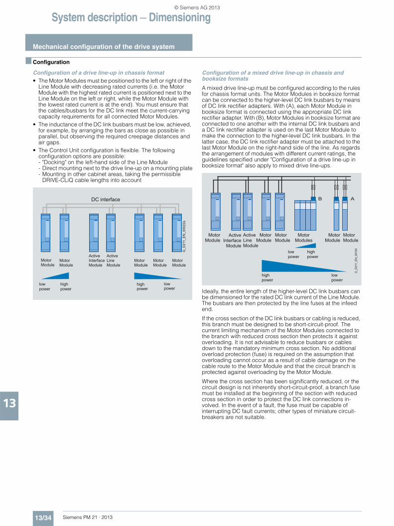
System description — Dimensioning
Mechanical configuration of the drive system
13/34 Siemens PM 21 · 2013
13
■ Configuration
Configuration of a drive line-up in chassis format• The Motor Modules must be positioned to the left or right of the
Line Module with decreasing rated currents (i.e. the Motor Module with the highest rated current is positioned next to the Line Module on the left or right, while the Motor Module with the lowest rated current is at the end). You must ensure that the cables/busbars for the DC link meet the current-carrying capacity requirements for all connected Motor Modules.
• The inductance of the DC link busbars must be low, achieved, for example, by arranging the bars as close as possible in parallel, but observing the required creepage distances and air gaps.
• The Control Unit configuration is flexible. The following configuration options are possible: - "Docking" on the left-hand side of the Line Module- Direct mounting next to the drive line-up on a mounting plate- Mounting in other cabinet areas, taking the permissible
DRIVE-CLiQ cable lengths into account
Configuration of a mixed drive line-up in chassis and booksize formats
A mixed drive line-up must be configured according to the rules for chassis format units. The Motor Modules in booksize format can be connected to the higher-level DC link busbars by means of DC link rectifier adapters. With (A), each Motor Module in booksize format is connected using the appropriate DC link rectifier adapter. With (B), Motor Modules in booksize format are connected to one another with the internal DC link busbars and a DC link rectifier adapter is used on the last Motor Module to make the connection to the higher-level DC link busbars. In the latter case, the DC link rectifier adapter must be attached to the last Motor Module on the right-hand side of the line. As regards the arrangement of modules with different current ratings, the guidelines specified under "Configuration of a drive line-up in booksize format" also apply to mixed drive line-ups.
Ideally, the entire length of the higher-level DC link busbars can be dimensioned for the rated DC link current of the Line Module. The busbars are then protected by the line fuses at the infeed end.
If the cross section of the DC link busbars or cabling is reduced, this branch must be designed to be short-circuit-proof. The current limiting mechanism of the Motor Modules connected to the branch with reduced cross section then protects it against overloading. It is not advisable to reduce busbars or cables down to the mandatory minimum cross section. No additional overload protection (fuse) is required on the assumption that overloading cannot occur as a result of cable damage on the cable route to the Motor Module and that the circuit branch is protected against overloading by the Motor Module.
Where the cross section has been significantly reduced, or the circuit design is not inherently short-circuit-proof, a branch fuse must be installed at the beginning of the section with reduced cross section in order to protect the DC link connections in-volved. In the event of a fault, the fuse must be capable of interrupting DC fault currents; other types of miniature circuit-breakers are not suitable.
MotorModule
MotorModule
ActiveInterfaceModule
MotorModule
MotorModule
MotorModule
ActiveLineModule
highpower
lowpower
highpower
low power
DC interface
G_D
211_
EN
_000
22a
G_D
211_
EN
_001
34
AB
MotorModule
MotorModule
MotorModule
MotorModules
MotorModule
MotorModule
ActiveInterface
Module
ActiveLineModule
highpower
lowpower
lowpower
high power
© Siemens AG 2013
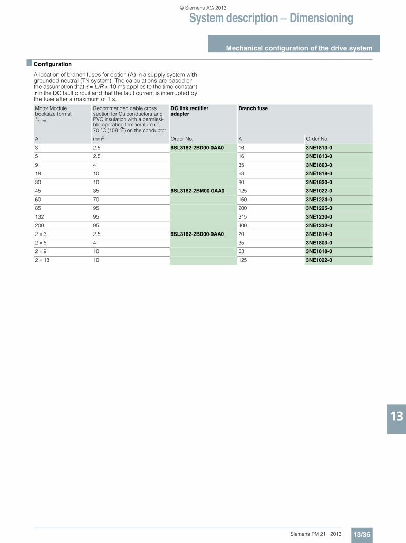
System description — Dimensioning
Mechanical configuration of the drive system
13/35Siemens PM 21 · 2013
13
■ Configuration
Allocation of branch fuses for option (A) in a supply system with grounded neutral (TN system). The calculations are based on the assumption that τ = L/R < 10 ms applies to the time constant τ in the DC fault circuit and that the fault current is interrupted by the fuse after a maximum of 1 s.
Motor Module booksize format Irated
Recommended cable cross section for Cu conductors and PVC insulation with a permissi-ble operating temperature of 70 °C (158 °F) on the conductor
DC link rectifier adapter
Branch fuse
A mm2 Order No. A Order No.
3 2.5 6SL3162-2BD00-0AA0 16 3NE1813-0
5 2.5 16 3NE1813-0
9 4 35 3NE1803-0
18 10 63 3NE1818-0
30 10 80 3NE1820-0
45 35 6SL3162-2BM00-0AA0 125 3NE1022-0
60 70 160 3NE1224-0
85 95 200 3NE1225-0
132 95 315 3NE1230-0
200 95 400 3NE1332-0
2 × 3 2.5 6SL3162-2BD00-0AA0 20 3NE1814-0
2 × 5 4 35 3NE1803-0
2 × 9 10 63 3NE1818-0
2 × 18 10 125 3NE1022-0
© Siemens AG 2013
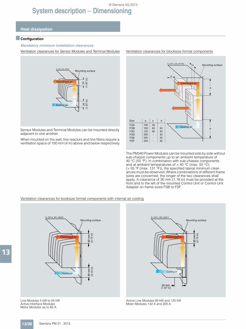
System description — Dimensioning
Heat dissipation
13/36 Siemens PM 21 · 2013
13
■ Configuration
Mandatory minimum installation clearances
Ventilation clearances for Sensor Modules and Terminal Modules
Sensor Modules and Terminal Modules can be mounted directly adjacent to one another.
When mounted on the wall, line reactors and line filters require a ventilation space of 100 mm (4 in) above and below respectively.
Ventilation clearances for blocksize format components
The PM340 Power Modules can be mounted side by side without sub-chassis components up to an ambient temperature of 40 °C (55 °F). In combination with sub-chassis components and at ambient temperatures of > 40 °C (max. 55 °C) (> 55 °F (max. 131 °F)), the specified lateral minimum clear-ances must be observed. Where combinations of different frame sizes are concerned, the longer of the two clearances shall apply. A clearance of 30 mm (1.18 in) must be provided at the front and to the left of the mounted Control Unit or Control Unit Adapter on frame sizes FSB to FSF.
Ventilation clearances for booksize format components with internal air cooling
Line Modules 5 kW to 55 kW Active Interface Modules Motor Modules up to 85 A
Active Line Modules 80 kW and 120 kW Motor Modules 132 A and 200 A
5050
Discharged air
Cooling air
Mounting surfaceG_D212_EN_00025
(1.9
7 in
)(1
.97
in)
aa
a100100125300300350
s
d
s d 30 40 50 - - -
- 30 30 30 30 30
FSAFSBFSCFSDFSEFSF
Mounting surface
Discharged air
Cooling air
G_D211_EN_00135a
Size
80 m
m80
mm
Mounting surface
Discharged air
Cooling air
G_D212_EN_00023
(3.1
5 in
)(3
.15
in)
80 m
m
50 mm
Mounting surface
Discharged air
Cooling air
G_D211_EN_00211
(3.1
5 in
)
(1.97 in)
© Siemens AG 2013
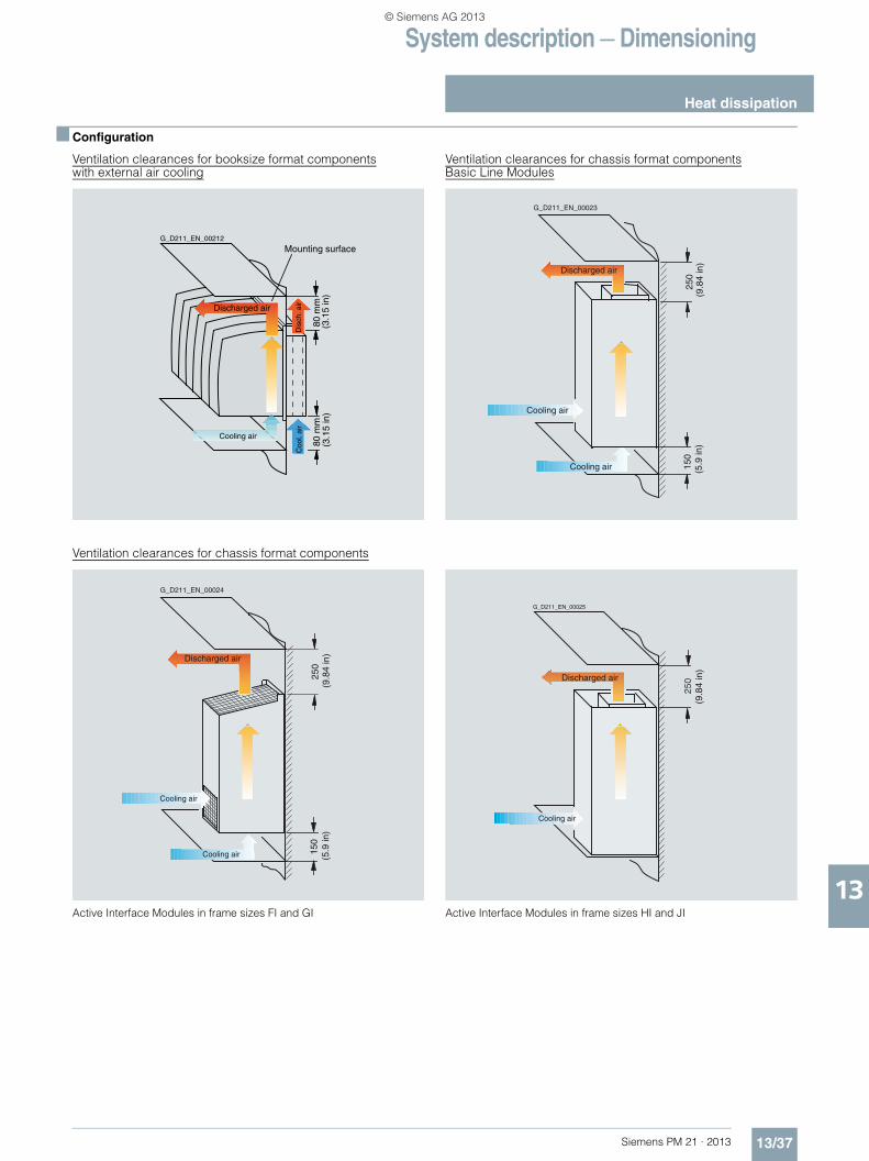
System description — Dimensioning
Heat dissipation
13/37Siemens PM 21 · 2013
13
■ Configuration
Ventilation clearances for booksize format componentswith external air cooling
Ventilation clearances for chassis format componentsBasic Line Modules
Ventilation clearances for chassis format components
Active Interface Modules in frame sizes FI and GI Active Interface Modules in frame sizes HI and JI
80 m
m80
mm
Mounting surface
Cooling air
G_D211_EN_00212
(3.1
5 in
)(3
.15
in)
Discharged airD
isch
. air
Coo
l. ai
r
Discharged air
Cooling air
G_D211_EN_00023
250
150
Cooling air
(9.8
4 in
)(5
.9 in
)
150
250
Discharged air
Cooling air
G_D211_EN_00024
Cooling air
(9.8
4 in
) (5
.9 in
)
250 Discharged air
Cooling air
G_D211_EN_00025
(9.8
4 in
)
© Siemens AG 2013
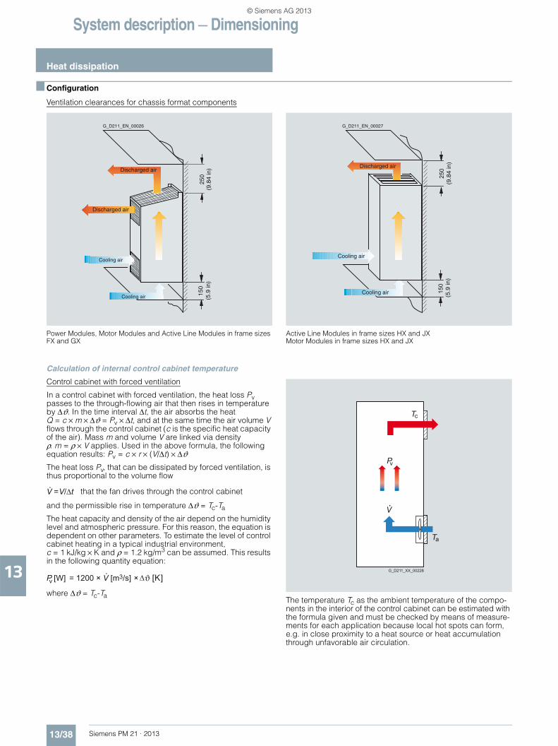
System description — Dimensioning
Heat dissipation
13/38 Siemens PM 21 · 2013
13
■ Configuration
Ventilation clearances for chassis format components
Power Modules, Motor Modules and Active Line Modules in frame sizes FX and GX
Active Line Modules in frame sizes HX and JXMotor Modules in frame sizes HX and JX
Calculation of internal control cabinet temperature
Control cabinet with forced ventilation
In a control cabinet with forced ventilation, the heat loss Pv passes to the through-flowing air that then rises in temperature by Δϑ. In the time interval Δt, the air absorbs the heat Q = c × m × Δϑ = Pv × Δt, and at the same time the air volume V flows through the control cabinet (c is the specific heat capacity of the air). Mass m and volume V are linked via density ρ. m = ρ × V applies. Used in the above formula, the following equation results: Pv = c × r × (V/Δt) × ΔϑThe heat loss Pv, that can be dissipated by forced ventilation, is thus proportional to the volume flow
and the permissible rise in temperature Δϑ = Tc-Ta
The heat capacity and density of the air depend on the humidity level and atmospheric pressure. For this reason, the equation is dependent on other parameters. To estimate the level of control cabinet heating in a typical industrial environment, c = 1 kJ/kg × K and ρ = 1.2 kg/m3 can be assumed. This results in the following quantity equation:
where Δϑ = Tc-TaThe temperature Tc as the ambient temperature of the compo-nents in the interior of the control cabinet can be estimated with the formula given and must be checked by means of measure-ments for each application because local hot spots can form, e.g. in close proximity to a heat source or heat accumulation through unfavorable air circulation.
150
250
Discharged air
Cooling air
G_D211_EN_00026
Cooling air
Discharged air(5
.9 in
) (9
.84
in)
150
250Discharged air
Cooling air
G_D211_EN_00027
Cooling air
(9.8
4 in
) (5
.9 in
)
V V/Δt= that the fan drives through the control cabinet
P [W] = 1200 × V [m3/s] × ϑ [K] v
Pv
c
V
T
aT
G_D211_XX_00228
© Siemens AG 2013
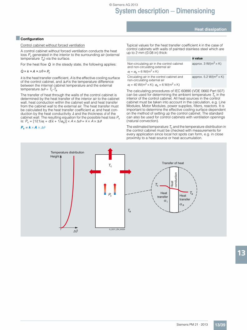
System description — Dimensioning
Heat dissipation
13/39Siemens PM 21 · 2013
13
■ Configuration
Control cabinet without forced ventilation
A control cabinet without forced ventilation conducts the heat loss Pv generated in the interior to the surrounding air (external temperature Ta) via the surface.
For the heat flow in the steady state, the following applies:
k is the heat transfer coefficient, A is the effective cooling surface of the control cabinet, and Δϑ is the temperature difference between the internal cabinet temperature and the external temperature Δϑ = Tc-Ta
The transfer of heat through the walls of the control cabinet is determined by the heat transfer of the interior air to the cabinet wall, heat conduction within the cabinet wall and heat transfer from the cabinet wall to the external air. The heat transfer must be calculated by the heat transfer coefficient α, and heat con-duction by the heat conductivity λ and the thickness d of the cabinet wall. The resulting equation for the possible heat loss Pv is: Pv = [1/(1/αi + d/λ + 1/αa)] × A × Δϑ = k × A × Δϑ
Pv = k × A × Δϑ
Typical values for the heat transfer coefficient k in the case of control cabinets with walls of painted stainless steel which are up to 2 mm (0.08 in) thick:
The calculating procedures of IEC 60890 (VDE 0660 Part 507) can be used for determining the ambient temperature Tc in the interior of the control cabinet. All heat sources in the control cabinet must be taken into account in the calculation, e.g. Line Modules, Motor Modules, power supplies, filters, reactors. It is important to determine the effective cooling surface dependent on the method of setting up the control cabinet. The standard can also be used for control cabinets with ventilation openings (natural convection).
The estimated temperature Tc and the temperature distribution in the control cabinet must be checked with measurements for every application since local hot spots can form, e.g. in close proximity to a heat source or heat accumulation.
Q
v= k × A ×Q = Pϑ
k value
Non-circulating air in the control cabinet and non-circulating external airαi = αa = 6 W/(m2 × K)
approx. 3 W/(m2 × K)
Circulating air in the control cabinet and non-circulating external airαi = 40 W/(m2 × K); αa = 6 W/(m2 × K)
approx. 5.2 W/(m2 × K)
P
cT
cT
aT
aT
ia
G_D211_EN_00229
HeightTemperature distribution
Transfer of heat
Hea
t co
nduc
tion
Heat transfer Heat
transferv
© Siemens AG 2013
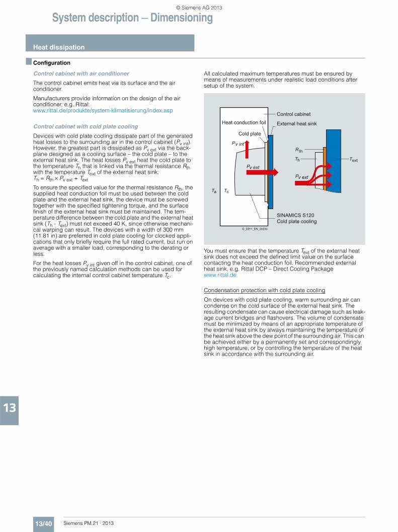
System description — Dimensioning
Heat dissipation
13/40 Siemens PM 21 · 2013
13
■ Configuration
Control cabinet with air conditioner
The control cabinet emits heat via its surface and the air conditioner.
Manufacturers provide information on the design of the air conditioner, e.g. Rittal:www.rittal.de/produkte/system-klimatisierung/index.asp
Control cabinet with cold plate cooling
Devices with cold plate cooling dissipate part of the generated heat losses to the surrounding air in the control cabinet (Pv int). However, the greatest part is dissipated as Pv ext via the back-plane designed as a cooling surface – the cold plate – to the external heat sink. The heat losses Pv ext heat the cold plate to the temperature Th that is linked via the thermal resistance Rth with the temperature Text of the external heat sink: Th = Rth × Pv ext + Text
To ensure the specified value for the thermal resistance Rth, the supplied heat conduction foil must be used between the cold plate and the external heat sink, the device must be screwed together with the specified tightening torque, and the surface finish of the external heat sink must be maintained. The tem-perature difference between the cold plate and the external heat sink (Th - Text) must not exceed 40 K, since otherwise mechani-cal warping can result. The devices with a width of 300 mm (11.81 in) are preferred in cold plate cooling for clocked appli-cations that only briefly require the full rated current, but run on average with a smaller load, corresponding to the derating or less.
For the heat losses Pv int given off in the control cabinet, one of the previously named calculation methods can be used for calculating the internal control cabinet temperature Tc.
All calculated maximum temperatures must be ensured by means of measurements under realistic load conditions after setup of the system.
You must ensure that the temperature Text of the external heat sink does not exceed the defined limit value on the surface contacting the heat conduction foil. Recommended external heat sink, e.g. Rittal DCP – Direct Cooling Packagewww.rittal.de
Condensation protection with cold plate cooling
On devices with cold plate cooling, warm surrounding air can condense on the cold surface of the external heat sink. The resulting condensate can cause electrical damage such as leak-age current bridges and flashovers. The volume of condensate must be minimized by means of an appropriate temperature of the external heat sink by always maintaining the temperature of the heat sink above the dew point of the surrounding air. This can be achieved either by a permanently set and correspondingly high temperature, or by controlling the temperature of the heat sink in accordance with the surrounding air.
cTaT
P
P
P
hT T
R th
ext
G_D211_EN_00230
SINAMICS S120Cold plate cooling
Heat conduction foil
Cold plate
External heat sink
Control cabinet
v int
v ext
v ext
© Siemens AG 2013