system and software behavior modeling language (version 4.0)
TRANSCRIPT

MPv.4.0 Draft modified: March3,2020
1of152
SystemandSoftwareBehaviorModelingLanguage
(version4.0)
Mikhail Auguston Computer Science Department
Naval Postgraduate School Monterey, California, USA

MPv.4.0 Draft modified: March3,2020
2of152
Public server running web app with MP editor, trace generator, and trace graph visualization is available: MP version 4 at https://4.firebird.nps.edu/ MP wiki site: https://wiki.nps.edu/display/MP/Monterey+Phoenix+Home
Not yet implemented MP constructs are highlighted in red. Material contained herein is made available for the purpose of peer review and discussion and does not necessarily reflect the views of US Department of the Navy or US Department of Defense. DISTRIBUTION A. Approved for Public Release; distribution unlimited.

MPv.4.0 Draft modified: March3,2020
3of152
Table of Contents
1. Introduction........................................................................................................................52. BehaviormodelsinMP....................................................................................................62.1 Eventconcept..........................................................................................................................62.2 Eventgrammar.......................................................................................................................62.3 Behaviorcompositionandcoordination.........................................................................92.3.1 Aspect-OrientedParadigminMP.......................................................................................................11
2.4 Dataitemsasbehaviors....................................................................................................112.5 Behavioroftheenvironment...........................................................................................122.6 ContextconditionswithENSURE....................................................................................142.7 Nestedcompositionoperationsandqueries...............................................................152.8 ThreadswithSUCHTHATconditionandreshufflingoption..................................162.9 ‘Virtual’events.....................................................................................................................182.10 Assertionchecking..............................................................................................................202.11 Traceannotationandqueriesabouttraces.................................................................212.12 Businessprocessmodeling..............................................................................................242.13 Processmodeling:takeoffintothenextdimension..................................................262.14 User-definedrelations.......................................................................................................302.15 Cybersecuritymodels........................................................................................................342.16 Eventattributes...................................................................................................................382.16.1 Intervalattributetype........................................................................................................................402.16.2 Timingattributes...................................................................................................................................42
2.17 Avoidingdeadlocksinthreads–DiningPhilosophers.............................................462.18 ModelingFiniteStateMachines......................................................................................482.18.1 ModelingModelCheckerandtemporallogicformulae....................................................492.18.2 ModelingPetrinetinMP...................................................................................................................52
2.19 Coordinatingasynchronousthreadsandtrackingdependencychains...............552.20 ProbabilisticmodelsinMP...............................................................................................572.20.1 Probabilityofeventtrace..................................................................................................................582.20.2 Probabilityofaneventwithinatrace........................................................................................60
2.21 MPmodelreuse...................................................................................................................642.21.1 Compilerfrontendmodel’sreuse................................................................................................652.21.2 ReusewiththeMAPcompositionoperation..........................................................................69
3. NotesonMPsemantics–howtracederivationworks..........................................724. SomeheuristicsforMPcodedesign...........................................................................754.1 Usescopewithcaution......................................................................................................754.2 Usecompositionoperationsasearlyaspossible.......................................................754.3 UseBUILDblocks.................................................................................................................754.4 OptimizationofCOORDINATEoperations....................................................................764.5 Useasynchronouscoordinationwithcaution.............................................................764.6 Coordinationanditeration...............................................................................................764.7 Coordinationandalternatives.........................................................................................774.8 Synchronizingiterationcyclesandcoordination......................................................774.9 Mergeandconquer.............................................................................................................794.10 Divideandconquer.............................................................................................................81

MPv.4.0 Draft modified: March3,2020
4of152
5. Dependencyrelationsandcustomviewpoints.......................................................885.1 Traceviewsandglobalviews..........................................................................................905.2 Reports...................................................................................................................................935.3 Graphs....................................................................................................................................955.3.1 Graphsascontainerdatastructures..............................................................................................1015.3.2 Extractingstatetransitiondiagramfromeventtraces........................................................102
5.4 GLOBALattributesandGLOBALqueries....................................................................1075.5 Tablesandcharts..............................................................................................................1115.5.1 Histograms..................................................................................................................................................1125.5.2 Ganttcharts.................................................................................................................................................114
5.6 UMLactivitydiagrams.....................................................................................................1156. MPlanguageconstructs..............................................................................................1176.1 Lexics....................................................................................................................................1176.2 ExtendedBNFnotationforMPsyntax.........................................................................1186.3 Eventgrammarrules........................................................................................................1186.4 Eventpatterns....................................................................................................................1196.5 Navigationdirections.......................................................................................................1216.6 Compositionoperations..................................................................................................1236.7 Eventattributes.................................................................................................................1326.8 Buildblocks........................................................................................................................1336.9 Expressions.........................................................................................................................1346.10 Aggregateoperations.......................................................................................................1386.11 Customviews......................................................................................................................139
7. Appendices.....................................................................................................................1447.1 Axiomsforbasicrelations..............................................................................................1447.2 Relationalexpressions....................................................................................................1457.3 Timingattributecalculationalgorithms....................................................................1457.4 MPkeywords......................................................................................................................1467.5 MPpre-definedattributenamesandfunctions........................................................1487.6 MPmeta-symbols..............................................................................................................148
8. Briefrelatedworknotes............................................................................................148
9. Acknowledgments........................................................................................................149
10. References..................................................................................................................150

MPv.4.0 Draft modified: March3,2020
5of152
1. INTRODUCTION Monterey Phoenix (MP) is a framework for software system architecture and business process (workflow) specification based on behavior models [Auguston, 2009a, 2009b, 2014]. Usually architectureplaysroleofabridgebetweenrequirementsandsystem’simplementation,andrepresentsastepwise refinement in thedesignprocesswithspecificobjectivesandstakeholders.Business process model often represents a part of the system’s requirements, where interactions between the system and its environment is an integral part of architecture specification.
Software design involves finding an algorithm for solving the problem at hand and mapping it on the appropriate computational platform. An algorithm commonly is specified as a behavior applying a step-by-step procedure to solve the problem at hand. An architecture description belongs to a high level of abstraction, ignoring many details of the algorithm implementation and data structures.
In common software architecture models the main elements are components (representing the functionality) and connectors (representing the information flow between components). Both components and connectors are abstractions of behaviors. MP provides an executable architecture model and behavior modeling is at the core of MP approach. The main MP concepts are activities (or events) and coordination between them, based on the following principles.
• A view of the architecture as high-level description of possible system behaviors, emphasizing the dependencies in behavior of subsystems (components) and interactions between them. MP introduces the concept of event as an abstraction of activity.
• The separation of the interaction description from the component’s behavior is an essential MP feature. It provides for a high level of abstraction and supports the reuse of architectural models. Interactions between activities are modeled using event coordination constructs.
• The environment’s behavior is an integral part of the system’s model. MP provides a uniform method for modeling behaviors of the software, hardware, business processes, and other parts of the system.
• The event grammar models the behavior as a set of events (event trace) with two basic relations, where the PRECEDES relation captures the direct dependency abstraction, and the IN relation represents the hierarchical relationship. Since the event trace is a set, additional constraints can be specified using set-theoretical operations and predicate logic.
• The MP architecture description is amenable to deriving multiple views (or abstractions), and provides a uniform basis for specifying both structural and behavioral aspects of a system.
• MP models are executable. MP tools support automated and exhaustive (for a given scope) scenario (or event trace) generation for early system architecture verification. The Small Scope Hypothesis [Jackson 2006] states that most flaws in models could be demonstrated on relatively small counterexamples. Testing and debugging architecture models is supported by assertion checking for verifying the behavior properties.
• Event traces are simple models of behavior instances, and humans understand them better than complete formal models. Scenarios (or use cases) generated by MP can facilitate communication with system’s stakeholders.
• MP framework can assist in providing unifying basis for UML activity and sequence diagrams, Statecharts, and recent Executable UML Alf language [OMG 2010] for behavior specification. MP may be used in addition to the existing architecture definition tools and methodologies.
MP is intended for the use in software and system architecture design and maintenance as a lightweight Formal Method. It provides an ecosystem for sanity checking tools, reusable architecture patterns, reusable assertions, queries, and tools for extracting architecture views.

MPv.4.0 Draft modified: March3,2020
6of152
In general, there are two major approaches to formal specification languages: data-centered and action-centered. Examples of data-centered approaches include type theories, first order predicate logic, entity-relation models, and relational logic [Jackson 2006]. Action-centered formalisms include finite state machines (finite automata, Statecharts, Petri nets, model checking), different kinds of flowcharts, temporal logics, process algebras [Hoare 1985], [Milner 1989], and algebraic specification systems (axioms about operations on data structures). Of course, some formal specification languages attempt to merge both paradigms. MP can be considered as action-centered formalism with emphasis on system behavior specification, although the data items when needed can be managed as well (see Sec. 2.4 for more details).
2. BEHAVIOR MODELS IN MP In a certain sense, the source code of a program is a compact description for a set of required behaviors. The source code in any programming language – a finite object by itself – specifies a potentially infinite number of execution paths. The behavior of the system is usually the main concern for the developer, and the presence of unintended behaviors manifests errors in the design. A system is operating in a certain environment, which has its own behavior and interacts with the system. The objective of the MP approach is to provide a framework for specifying behaviors of the system, its parts and its environment, and interactions between them. The purpose of any model is to help answer questions. MP model is designed to answer questions about system’s behaviors, including such aspects as structure of behavior, dependencies between actions involved in the behavior, constraints on behaviors, and to provide a source for different visualizations or views of behaviors. 2.1 Event concept The MP behavior model is based on the concept of event as an abstraction of activity. The event has a beginning and an end, and may have duration (a time interval during which the action is accomplished). The behavior of a system is modeled as a set of events with two binary relations defined for them: precedence (PRECEDES) and inclusion (IN) – the event trace. One action is required to precede another if there is a dependency between them, e.g. the Send event should precede the Receive event. Events may be nested, when a complex activity contains a set of other activities. Defining one of these basic relations for a pair of events represents an important design decision. Usually system behavior does not require a total ordering of events. Both PRECEDES and IN are partial ordering relations. If two events are not ordered, they may overlap in time, in particular, they may occur concurrently. Section 7.1 provides axioms specifying the properties of basic relations. 2.2 Event grammar The MP model of system’s behavior is written as a schema – a collection of rules describing behavior of components within the system, external actors, and their interactions. The structure of possible event traces is described by event grammar. A grammar rule specifies structure for a particular event type (in terms of IN and PRECEDES relations) and has a form A: pattern_list; where A is an event type name and pattern_list is composed from event patterns. Event types that do not appear in the lefthand part of rules are considered atomic and may be refined later by adding corresponding rules.

MPv.4.0 Draft modified: March3,2020
7of152
An instance of an event trace satisfying the grammar rule can be visualized as a directed graph with two types of edges (one for each of the basic relations). Events are visualized as boxes, and basic relations as arrows. Fig. 1 outlines the event patterns for use in the grammar rule’s righthand part. Here A, B, C stand for event type names or event patterns. Sequence denotes ordering of events under the PRECEDES relation. The grammar rule A: B C means that an event a of the type A contains ordered instances of events b and c matching B and C, correspondingly, and relations b IN a, c IN a, and b PRECEDES c hold. In Fig. 1 boxes denote event instances, dashed arrows - IN relations, and solid arrows – PRECEDES relations.
Fig. 1. Event grammar rules and examples of event trace instances.
Pattern (+ B +) denotes a sequence of one or more event B instances under PRECEDES relation. It is similar to (* B *) with one additional constraint: there should be at least one B instance in the sequence. {+ B +} denotes a set of one or more events B. In all cases it is assumed that iterated event instances are unique. Iteration is used to describe repeated behavior patterns. An event grammar is a grammar for directed acyclic graphs of vertices (events) with edges representing relations IN and PRECEDES. An event trace represents an instance of a particular execution of the system or a use case, especially if the behavior of the environment is included. Event traces can be effectively derived from the event grammar rules and then adjusted and filtered according to the composition operations and constraints in the schema. This justifies the term executable architecture model. For a given MP schema it is possible to obtain all valid event traces up to a certain limit. Usually such a limit (scope) is set as the upper limit on the number of iterations in grammar rules (recursion can be limited in a similar way, but current Firebird MP tool does not allow explicit or implicit recursion in event grammar rules). For most purposes a modest limit of 3 iterations will be sufficient. The process of generating and inspecting event traces for the schema is similar to the traditional software testing process.

MPv.4.0 Draft modified: March3,2020
8of152
Since it is possible to automatically generate all event traces within the given scope for MP model, it provides for exhaustive testing – a feature usually not available for traditional software testing. Careful inspection of generated traces (scenarios/use cases) may help developers to identify undesired behaviors. Usually it is easier to evaluate an example of behavior (particular event trace) than the generic description of all behaviors (the schema). The Small Scope Hypothesis [Jackson 2006] states that most errors can be demonstrated on relatively small counterexamples. Assertion checking and SAY clauses in MP make the event trace inspection easier. Any system, not only software, needs a systematic testing. The set of event traces generated from the MP model can be used for testing the system implementation for which the MP model has been designed as well. The exhaustive set of event traces generated for a given scope may provide a completeness criterion for the traditional “black box” testing of a software system at high enough, but still meaningful level of abstraction. Event grammar notation is conceptually close to the pseudo-code notation used in software design [Knuth, 1984]. MP architecture model can be refined up to the quite detailed design model. Event names can be considered as pseudo-code statements, and the imperative control structures can be modeled in MP as follows. Behavior of the conditional statement if Condition then Statement1 else Statement2 is modeled in MP with the event pattern Check_Condition ( Condition_is_true Perform_Statement1 |
Condition_is_false Perform_Statement2 ) Behavior of terminating loop, where loop body is executed zero or more times while(Condition) do Loop_bodyis modeled as Check_Condition (* Condition_is_true
Perform_Loop_body Check_Condition
*) Condition_is_false Behavior of terminating loop, where loop body is executed one or more timesrepeat Loop_body until (Condition) is modeled as (* Perform_Loop_body
Check_Condition Condition_is_false
*) Perform_Loop_body Check_Condition

MPv.4.0 Draft modified: March3,2020
9of152
Condition_is_true Section5.6providesexamplesofmappingMPconstructsintoUML/SysMLactivitydiagrams,orintotraditionalflowcharts.
2.3 Behavior composition and coordination The behavior of a particular system is specified as a set of possible event traces using a schema. The purpose is to define the structure of event traces in terms of IN and PRECEDES relations using event grammar rules and other constraints. A schema contains a collection of events called roots representing the behaviors of parts of the system (components and connectors in common architecture descriptions), composition operations specifying interactions between these behaviors, and additional constraints on behaviors. There is precisely one instance of each root event in a trace. A schema can contain auxiliary grammar rules for composite event types used in other rules. In principle schema may define both finite and infinite traces, but most analysis tools for reasoning about a system’s behavior assume that a trace is finite. Only finite event traces are considered in current MP tools (including Firebird). The schema represents instances of behavior (event traces) in the same sense as Java source code represents instances of program execution. Just as a particular execution path can be extracted from a Java source code by running it on a JVM, a particular event trace specified by MP schema can be derived from the event grammar rules by applying composition operations and constraints. Example 1. Simple interaction pattern. SCHEMA simple_message_flow ROOT Sender: (* send *); ROOT Receiver: (* receive *); COORDINATE $x: send FROM Sender, $y: receive FROM Receiver DO ADD $x PRECEDES $y; OD; The composition operation COORDINATE coordinates behaviors of two root events sending and receiving messages. This trace operation takes two root event traces and produces a modified event trace (merging behaviors of Sender and Receiver) by adding the PRECEDES relation for the selected send and receive pairs. Essentially it is a loop performed over the structure of coordinated events, hence the DO - OD notation for the loop body. This COORDINATE composition uses event selection patterns to specify subsets of root traces that should be coordinated. The send pattern identifies the set of events selected from Sender. The default for event selection in the coordination source within COORDINATE preserves the order of events generated during the derivation process. The default means that the ordering of events in selected sets will remain “as is”. Both selected event sets should have the same number of elements (send events from the first trace and receive events from the second), and the pair coordination follows their ordering (synchronous coordination), i.e. first send is paired with first receive, second with the second, and so on. MP variables $x and $y provide access to the pair of events matching the selection pattern within each iteration. The ADD operation completes the behavior adjustment, specifying additional PRECEDES

MPv.4.0 Draft modified: March3,2020
10of152
relation for each pair of selected events. Behavior specified by this schema is a set of matching event traces for Sender and Receiver with the modifications imposed by the composition. If the numbers of events in the selected event sets (coordination sources) are not equal, the coordination operation fails to produce a resulting trace. The reshuffling operations may be applied to the default set before the coordination to rearrange events within the selected set (see Publish/Subscribe Example 7 in section 2.8, and ring topology Example 16 in section 2.14). The selection pattern may be either an event type name (atomic or composite), or an alternative pattern composed of event type names. Fig. 2 gives a sample of event trace satisfying the schema simple_message_flow. It resembles a UML sequence diagram’s “swim lanes”. Different views (or abstractions) for different stakeholders can be extracted from MP schemas. For example, each root may be visualized as a box. If there is a composition operation specifying an interaction (or coordination) between root behaviors, the boxes are connected by an arrow as illustrated in Fig. 3. This diagram is obtained by collapsing root events in the Firebird’s graph window for a trace containing a representative set of events and relations. The root behavior by itself may be visualized with UML Activity Diagram [Booch et al. 2000].
Fig. 2. Example of a composed event trace for the simple_message_flow schema (scope 2).
Fig. 3. Architecture view for the simple_message_flow schema.
Another way of selecting event pairs is called asynchronous coordination. In this case the coordination source intended for asynchronous coordination should be marked with a symbol <!>. That is an event reshuffling operation performed before the body of coordination operation. For example, COORDINATE <!> $x: E1 FROM A, $y: E2 FROM B DO ADD $x PRECEDES $y; OD; Matching event sets from A and B should contain an equal number of selected events E1 and E2, correspondingly. But now the resulting merged traces will include all permutations of events E1 from A paired with the same (default) sequence of events E2 from B, with the PRECEDES relation imposed on each selected pair. This assumes that other constraints, like the axioms from Sec. 7.1, are

MPv.4.0 Draft modified: March3,2020
11of152
satisfied. Each permutation yields one potential instance of a resulting trace for the schema deploying this composition. Use of <!> may significantly increase the number of composed traces. Read about other options for event reshuffling within the coordination source in the rules event_reshuffling_option(31) and reshuffling_unit(33). The COORDINATE operation may be considered as an abstract interaction (interface) description for behaviors. The separation of the interaction description from the component’s behavior is an essential MP feature. The same component behavior may be reused with different interaction descriptions – a useful composition/reuse aspect. The COORDINATE operation may have multiple coordination sources (in a valid trace the number of selected events in each should be the same), and the same ADD operation may process several relations.
2.3.1 Aspect-Oriented Paradigm in MP The COORDINATE operation supports a “cause-effect” refinement for the behavior of two components and it bears a certain similarity to Aspect-Oriented Programming (AOP) paradigm [Kiczales et al. 1997] (or read https://en.wikipedia.org/wiki/Aspect-oriented_programming). For example, the following AOP pattern could be modeled by MP schema where event coordination implements AOP join point and advice coordination. Suppose that the main stream of execution contains calls to methods M1 and M2 as join points, and the aspect behavior requires a call to Prolog before, and to Epilog after each method call as an advice. The corresponding MP model may look like the following. Example 2. Modeling Aspect-Oriented Paradigm. SCHEMA AOP ROOT Main: (* ( M1 | M2 | do_something_else ) *); ROOT PreAdvice: (* Prolog *); ROOT PostAdvice: (* Epilog *); COORDINATE $jp: ( M1 | M2 ) FROM Main, $a1: Prolog FROM PreAdvice, $a2: Epilog FROM PostAdvice
DO ADD $a1 PRECEDES $jp, $jp PRECEDES $a2;
OD;
2.4 Data items as behaviors Data items in MP are represented by actions (events) that may be performed on that data. This principle follows the Abstract Data Type (ADT) concept introduced in [Liskov, Zilles 1974]. Example 3. Data flow. SCHEMA Data_flow
ROOT Writer: (* ( working | writing ) *);
/* writing events should precede reading */

MPv.4.0 Draft modified: March3,2020
12of152
ROOT File: (+ writing +) (* reading *);
Writer, File SHARE ALL writing; ROOT Reader: (* ( reading | working ) *);
Reader, File SHARE ALL reading; The behavior of File requires writing events to be completed before reading events, and there should be at least one writing event. The SHARE ALL composition operations ensure that the schema admits only event traces where corresponding event sharing is implemented.
Event sharing is defined as following (here X, Y are events, Z is an event type, and FROM is a transitive closure of IN, <-> means “if and only if”).
X, Y SHARE ALL Z <-> { v: Z | v FROM X } = { w: Z | w FROM Y }
Events to be shared are of the same type (have the same event type name) and hence have the same event attribute signature (see 2.15), If the values of corresponding event attributes are not equal, the SHARE ALL operation fails, and the failure is propagated to the enclosing BUILD block or schema. There is one exception. Time attributes depend on basic relations and are recalculated automatically each time when basic relations of an event are adjusted in the derivation process. When a pair of events is SHAREd, their relations (basic and user-defined) are merged, and this may trigger time attribute recalculation. The order of shared events is either the default, or can be specified by the SHARE_clause(44) combined with event reshuffling option (31). Event sharing is yet another way of behavior coordination. It is assumed that shared events may appear within an event at any level of nesting. At the architectural level data items are inputs or outputs of activities and are modeled as operations that may be performed on them. This is simple and uniform concept.
Fig. 4. An example of composed event trace for the Data_flow schema.
2.5 Behavior of the environment The following example demonstrates how to integrate the behavior models of an environment and a system that operates in this environment. The ATM_withdrawal schema specifies a set of possible interactions between the Customer, ATM_system, and Data_Base. Example 4. Withdraw money from ATM.

MPv.4.0 Draft modified: March3,2020
13of152
SCHEMA ATM_withdrawal ROOT Customer: (* insert_card ( identification_succeeds request_withdrawal ( get_money | not_sufficient_funds ) | identification_fails )
*); ROOT ATM_system: (* read_card
validate_id
( id_successful check_balance ( sufficient_balance
dispense_money | unsufficient_balance ) |
id_failed )
*); COORDINATE $x: insert_card FROM Customer, $y: read_card FROM ATM_system DO ADD $x PRECEDES $y; OD; COORDINATE $x: request_withdrawal FROM Customer, $y: check_balance FROM ATM_system DO ADD $x PRECEDES $y; OD; COORDINATE $x: identification_succeeds FROM Customer, $y: id_successful FROM ATM_system DO ADD $y PRECEDES $x; OD; COORDINATE $x: get_money FROM Customer, $y: dispense_money FROM ATM_system DO ADD $y PRECEDES $x; OD; COORDINATE $x: not_sufficient_funds FROM Customer, $y: unsufficient_balance FROM ATM_system DO ADD $y PRECEDES $x; OD; COORDINATE $x: identification_fails FROM Customer, $y: id_failed FROM ATM_system DO ADD $y PRECEDES $x; OD; ROOT Data_Base: (* validate_id [ check_balance ] *); /* the structure of Data_Base behavior follows the pattern of events validate_id and check_balance
in ATM_system, so that these two streams of events could be coordinated with SHARE ALL for any scope */
Data_Base, ATM_system SHARE ALL validate_id, check_balance;

MPv.4.0 Draft modified: March3,2020
14of152
Fig. 5. An example of event trace for ATM_withdrawal schema.
An event trace generated from the schema can be considered as a use case example. The event trace on Fig. 5 can be viewed also as an analog of UML sequence diagram’s “swim lanes” for Customer and ATM_system interactions.
The concept of environment in an architecture model includes behavior of other systems, hardware, business processes, and any other behaviors, which are not part of the system under consideration, but may interact with it. In particular, this approach may be of use for analyzing emergent behaviors of System of Systems, when the model of SoS is composed from the models of its components.
2.6 Context conditions with ENSURE The event trace is a set of events and the Boolean expressions in MP can embrace the traditional predicate calculus notation. A set of behaviors (event traces) may be defined by the event grammar rules, composition operations, and some additional constraints – ENSURE conditions. Example 5. Stack behavior. Stack implements the “last in, first out” behavior for storing/retrieving elements. It is assumed that initially Stack is empty. SCHEMA Stack_behavior ROOT Stack: (* ( push | pop ) *)
BUILD { /* If an element is retrieved, it should have been stored before */
ENSURE FOREACH $x: pop FROM Stack ( #pop BEFORE $x < #push BEFORE $x );
};

MPv.4.0 Draft modified: March3,2020
15of152
This rule specifies the behavior of a stack in terms of stack operations push and pop. The BUILD block associated with a root or composite event contains composition operations performed when event trace segment representing the behavior of that root or composite is generated. The ENSURE Boolean expression provides a condition that each valid trace should satisfy. The domain of the universal quantifier is the set of all pop events inside Stack. The FROM Stack part is optional, by default it is assumed to be FROM THIS. The function #pop BEFORE $x yields the number of pop events preceding $x. The set of valid event traces specified by this schema contains only traces that satisfy the constraint. This example presents a filtering operation as yet another kind of behavior composition, and demonstrates an example of combining imperative (event grammar) and declarative (Boolean expressions) constructs for behavior specification. Example 17 provides more advanced version of Stack behavior model.
Fig. 6. Stack behavior, trace #22 for scope 5
2.7 Nested composition operations and queries The following example demonstrates some MP techniques for coordination and simple queries about trace properties. Notice when event name E is used in the standard function call #E, the event name E should appear in some grammar rule before function call. Accordingly, composite event Car is placed before the root Cars to introduce event names drive_lap and finish used in the Cars BUILD block. Example 6. Car race. SCHEMA Car_Race /* Root event Cars is a set of concurrent events, each modeling the behavior of a single Car;
there should be at least one Car in the car race. */ ROOT Cars: {+ Car +} /* Following are context conditions local for the root Cars */ BUILD{ /* everybody who finishes drives the same number of laps */ ENSURE FOREACH DISJ $c1: Car, $c2: Car (#finish FROM $c1 == 1 AND #finish FROM $c2 == 1 ->

MPv.4.0 Draft modified: March3,2020
16of152
#drive_lap FROM $c1 == #drive_lap FROM $c2) AND /* if it breaks, then earlier */ (#finish FROM $c1 == 1 AND #break FROM $c2 == 1 -> #drive_lap FROM $c1 >= #drive_lap FROM $c2); /* there always will be at most one winner */ ENSURE #winner <= 1; /* if at least one car finishes, there should be a winner */ ENSURE #finish > 0 -> #winner > 0; }; /* end Cars */ /* Composite event Car encapsulates the behavior of a single car */ Car: start (* drive_lap *) /* not every car will finish, sometimes a car that finishes is also a winner */ ( finish [ winner ] | break); ROOT Judge: provide_start_signal watch
/* Judge will monitor the finish events for Cars */ (* finish *); /* one-many coordination can be achieved with nested COORDINATE */ COORDINATE $a: provide_start_signal FROM Judge
DO COORDINATE $b: start FROM Cars DO ADD $a PRECEDES $b; OD; OD; /* ordering of finish events in concurrent Car threads can be achieved by coordinating them
with finish event sequence in the Judge root */ Cars, Judge SHARE ALL finish; /* now, when the ordering of finish events is ensured, we can specify another constraint:
the winner is the car, that finishes first */ COORDINATE $w: winner DO ENSURE #finish BEFORE $w == 1; OD; /* this is an example of a query annotating the trace with data specific for the trace */ SAY("In this race " #finish " cars have finished");
2.8 Threads with SUCH THAT condition and reshuffling option Example 7. Publish/Subscribe architecture model. Publisher sends a notification to all active Subscribers when new information is available. SCHEMA Publish_Subscribe ROOT Publisher: Register (+ <2.. 3 + $$scope * 2> ( Register | Unsubscribe | Send ) +) /* Iteration_scope <2.. 3 + $$scope * 2> is needed to provide enough events for coordination,

MPv.4.0 Draft modified: March3,2020
17of152
since each Client has Register/Unsubscribe event pair, plus some Receive events */ BUILD{ /* The Register and Unsubscribe events should be balanced */
ENSURE #Register == #Unsubscribe;
ENSURE FOREACH $u: Unsubscribe #Register BEFORE $u > #Unsubscribe BEFORE $u;
/* Publisher will Send only if there is at least one active Client. This condition is specified with ENSURE. */
ENSURE FOREACH $s: Send #Register BEFORE $s > #Unsubscribe BEFORE $s;
}; Client: Register (* Receive *) Unsubscribe; ROOT Subscribers: {+ Client +}; /****** Coordination between Publisher and Subscribers ******/ /* The ordering of composition operations is important, since Register and Unsubscribe events are used to coordinate Send/Receive between Publisher and Client. First, we do SHARE ALL for Register events, next will try all valid permutations of Register/Unsubscribe, and then proceed with further coordination of Send/Receive, using the shared Register and Unsubscribe events as pivots to coordinate Send events for each Client */ /* Need to try all possible permutations of Register/Unsubscribe pairs, hence the use of <!> event reshuffling */ COORDINATE $r1: Register FROM Publisher,
<!> $r2: Register FROM Subscribers DO SHARE $r1 $r2; OD;
COORDINATE $u1: Unsubscribe FROM Publisher,
<!> $u2: Unsubscribe FROM Subscribers DO SHARE $u1 $u2; OD;
COORDINATE $client: Client FROM Subscribers
DO COORDINATE $reg: Register FROM $client, $uns: Unsubscribe FROM $client
/* For Send event selection to coordinate with a particular Client event, the SUCH THAT thread condition is used. Client will Receive all and only Send between his Register and Unsubscribe */
DO COORDINATE $r: Receive FROM $client, $s: Send FROM Publisher
SUCH THAT $s AFTER $reg AND $s BEFORE $uns /* Register and Unsubscribe events have been shared and now can be used to select appropriate Receive events from the Client and Send events from the Publisher for coordination */
DO ADD $s PRECEDES $r; OD; OD;
OD;

MPv.4.0 Draft modified: March3,2020
18of152
/* It might be interesting to find out whether there are Send events received by several Clients. MARK traces containing such event configuration, and place annotation pointing to the Send event of interest*/ COORDINATE $s: Send
DO IF (#Receive FOLLOWS $s > 1) THEN
MARK; ADD SAY("this Send is received by "
#Receive FOLLOWS $s " Clients") PRECEDES $s;
FI; OD;
Fig. 7. Publish_Subscribe example, Gryphon screenshot for scope 2, trace #10.
2.9 ‘Virtual’ events The concept of event provides an abstraction for building behavior models. Usually event’s name is a word or a short sentence in natural language (a pseudo-code) that denotes some activity performed within the system. But an event may denote also a lack of activity or other item of interest for specifying the behavior. For example, the event grammar rule Shooter: (* shoot (hit | miss) *); describes a meaningful and understandable set of behaviors (event traces), but the ‘virtual’ event miss rather denotes the absence of event hit. Example 8. Model of unreliable communication. Consider again Example 1 of message flow. We may want to specify behaviors when some messages get lost in the transition. It can be done using ‘virtual’ events. SCHEMA simple_message_flow

MPv.4.0 Draft modified: March3,2020
19of152
ROOT Sender: (* send *); ROOT Receiver: (* (receive | does_not_receive) *); COORDINATE $x: send FROM Sender, $y: (receive | does_not_receive) FROM Receiver DO ADD $x PRECEDES $y; OD;
Fig. 8. Unreliable communication, trace #13 for scope 3.
Example 9. Workflow pattern
The web site http://workflowpatterns.com/patterns/control/index.php contains a collection of workflow patterns specified with Petri nets. Pattern 9 (Structured Discriminator) at http://workflowpatterns.com/patterns/control/advanced_branching/wcp9.php : “When handling a cardiac arrest, the check_breathing and check_pulse tasks run in parallel. Once the first of these has completed, the triage task is commenced. Completion of the other task is ignored and does not result in a second instance of the triage task.” SCHEMA Cardiac_Arrest ROOT Phase1: { check_breathing [finish_first], check_pulse [finish_first] } BUILD{ ENSURE #finish_first == 1;}; ROOT Triage: identify_the_patient record_assessment_findings identify_the_priority; COORDINATE $a: finish_first,
$b: identify_the_patient DO ADD $a PRECEDES $b; OD; No event timing attributes are needed here. The ‘virtual’ event finish_first brings the right level of abstraction into this model. It addresses just the issue specified in the problem statement.

MPv.4.0 Draft modified: March3,2020
20of152
Fig. 9. Cardiac_Arrest model, traces #1 and #2, scope 1.
‘Virtual’ events help to write more comprehensive and readable models at the appropriate level of abstraction. They are “first_class_citizens”, and can participate in any relations and computations as other events do. Use of ‘virtual” events appears to be an important and useful methodology principle in MP.
2.10 Assertion checking MP models need to be tested and debugged like any other programming artifacts. Trace generation for a given scope (usually up to scope 3) yields exhaustive set of valid event traces. Browsing these traces may result in finding examples of behavior that are unwanted. Then we should fix the issue in the MP code, and run the trace generation again, until our expectations are satisfied. Browsing dozens or hundreds of event traces may be time consuming and error prone. The CHECK construct makes it possible to use automated trace monitoring. If the property (Boolean expression in the CHECK) is not satisfied, the trace will be marked and available for further inspection. This can significantly speed up the testing process. Of course, if the property should always hold, it makes sense to convert it into the ENSURE condition. Example 10. Communicating via unreliable channel. SCHEMA AtoB ROOT TaskA: (* A_sends_request_to_B ( A_receives_data_from_B |
A_timeout_waiting_from_B ) *);
ROOT Connector_A_to_B: (* A_sends_request_to_B
( B_receives_request_from_A B_sends_data_to_A ( A_receives_data_from_B |
A_timeout_waiting_from_B ) | A_timeout_waiting_from_B ) *); /* A_timeout_waiting_from_B may happen because Connector_A_to_B fails to pass a message
from A to B, or from B to A */ TaskA, Connector_A_to_B SHARE ALL A_sends_request_to_B, A_timeout_waiting_from_B, A_receives_data_from_B ;

MPv.4.0 Draft modified: March3,2020
21of152
ROOT TaskB: (* B_receives_request_from_A
B_sends_data_to_A *);
TaskB, Connector_A_to_B SHARE ALL B_receives_request_from_A, B_sends_data_to_A ;
/* assertion checking will mark examples of traces where TaskA does not receive the requested data and will attach a message to the trace */
CHECK #A_sends_request_to_B FROM TaskA == #A_receives_data_from_B FROM TaskA
ONFAIL SAY("loss of reception detected");
Fig. 10. Example of AtoB on Gryphon, scope 2, trace #8
2.11 Trace annotation and queries about traces Assertion checking with the CHECK clause may be the simplest and most common tool for finding counterexamples of traces, which violate some property. Traces violating the CHECK condition are marked, and the message provides some hint about the cause. The message is associated with the root, composite, or the whole schema, and further details may require browsing of the relevant trace segment. The following example demonstrates how to make messages more specific and focused. Let’s consider again the Stack model, but this time without the ENSURE constraint. This Stack certainly will produce unwanted behaviors. The MP code illustrates how to pinpoint events that might be violating certain property, and how to annotate these particular events in the trace with additional messages. Programmers will recognize the use of debugging print statements for traditional program testing/debugging. Example 11. Testing/Debugging model’s behavior. SCHEMA Unconstrained_Stack ROOT Stack: (* ( push | pop [ bang ]) *)
/* bang event models the Stack underflow event */ BUILD {
/* by default the domain for event selection is FROM THIS */ /* this is to make sure that each pop attempting to pop empty Stack is followed by bang event */

MPv.4.0 Draft modified: March3,2020
22of152
ENSURE FOREACH $p: pop /* pop associated with the bang event does not affect Stack contents,
hence only successful pop events count */ (#pop BEFORE $p - #bang BEFORE $p) >= #push BEFORE $p
<-> #bang FOLLOWS $p == 1; COORDINATE $b: bang /* pick up pop event immediately preceding bang */
DO COORDINATE $x: pop SUCH THAT $x PRECEDES $b DO
ADD SAY("This event tries to pop empty Stack") PRECEDES $x;
MARK; OD;
OD; }; Now traces where Stack behavior is incorrect will be MARKed and corresponding pop events will be pointed to by PRECEDES arrow leading from the message box associated with this event. Note that the sequence of pop push pop will trigger the message for the first pop event only, assuming that the second pop is not applied to empty stack. Trace annotation may improve the overall readability of use cases, generated by MP tools. Example 12. Queries about event trace. Pipe/Filter architecture. Trace annotation with SAY message boxes may facilitate better understanding of behaviors and help to navigate the list of derived traces. The assumptions for this pipe/filter architecture model with 2 Filters are as follows.
• Items send by Producer not always will be received by Consumer. • For each Filter the number of sent messages cannot exceed the number of received messages. • Received messages can stay in the Filter for while, before being send (if at all).
SAY messages can contain information specific for the trace instance (in this example, number of lost messages for Consumer), and could be used as queries to obtain specific data from the trace. For example, we could annotate only traces where messages were lost in both Filters. Attaching SAY boxes to particular events improves readability and helps to understand the behavior in more detail (in this example, annotations pointing to particular Filters, where a message got lost). Please also notice how to describe patterns for better coordination. We could use Filter: (* (* ( send | receive ) *) *) or Filter: (* ( send | receive ) *) to provide sufficient number of send/receive event sequences for coordination, but then the number of traces goes up dramatically and many of the valid traces are duplicates (because the same sequence of send/receive can be obtained from different configurations of these patterns). So, the proper choice of patterns for coordination may be very important.

MPv.4.0 Draft modified: March3,2020
23of152
The Filter’s behavior has a clear pattern: send can be done only after at least one receive. Filter: (* receive (* send *) *) This pattern yields an exhaustive set of possible send/receive sequences without duplication for any scope. SCHEMA Pipe_Filter ROOT Producer: (* send *);
ROOT Filter1: (* receive (* send *) *)
/* Filter can send only after receive */ BUILD {
ENSURE FOREACH $s: send (#receive BEFORE $s > #send BEFORE $s); /* annotate root’s trace if not everything received will be sent */ IF #send != #receive THEN
SAY("some messages have been lost in Filter1" ); FI;
};
COORDINATE $s: send FROM Producer, $r: receive FROM Filter1
DO ADD $s PRECEDES $r; OD;
ROOT Filter2: (* receive (* send *) *) BUILD {
ENSURE FOREACH $s: send (#receive BEFORE $s > #send BEFORE $s); IF #send != #receive THEN
SAY("some messages have been lost in Filter2" ); FI;
}; COORDINATE $s: send FROM Filter1,
$r: receive FROM Filter2 DO ADD $s PRECEDES $r; OD;
ROOT Consumer: (* receive *); COORDINATE $s: send FROM Filter2,
$r: receive FROM Consumer DO ADD $s PRECEDES $r; OD;
/* Annotate and MARK trace if Consumer does not receive all messages. This is an example of query providing data specific for this trace. */ IF #receive FROM Consumer != #send FROM Producer THEN
SAY( #send FROM Producer - #receive FROM Consumer " messages did not reach Consumer"); MARK;
FI;

MPv.4.0 Draft modified: March3,2020
24of152
Fig. 11. Pipe_Filter example, scope 2, trace #6
2.12 Business process modeling The web site http://www.infoq.com/articles/bpelbpm “Why BPEL is not the holy grail for BPM“ provides an example of a process that can be described in BPMN but not in BPEL. It is claimed to be a challenge for process specification. Here is the description. “When a new employee arrives at a company, a workflow is instantiated. First a record needs to be created in the Human Resources database. Simultaneously, an office has to be provided. As soon as the Human Resources activity has been completed, the employee can undergo a medical check. During that time, a computer is provided. This is only possible when both an office has been set up and an account created in the information system from the human resource database. When both the computer and the medical check have been performed, the employee is ready to work. Of course, you may want to model this simple process differently, but the point here is that you cannot define a structured parallel workflow [in BPEL] that is equivalent to this one..." The advantage of MP is in the ability to coordinate events at any location in the behavior hierarchy. Example 13. Business process model. SCHEMA Employee_Arrival ROOT Employee: SendArrivalDate MedicalCheck ReadyToWork; ROOT Employer: EmployeeArrival /* these are concurrent threads */ { Fill_HR_DB MedicalCheck, ProvideOffice ProvideComputer } ReadyToWork; Employee, Employer SHARE ALL MedicalCheck, ReadyToWork; COORDINATE $a: SendArrivalDate FROM Employee, $b: EmployeeArrival FROM Employer DO ADD $a PRECEDES $b; OD; /* coordination between two events deep inside the process */

MPv.4.0 Draft modified: March3,2020
25of152
COORDINATE $a: Fill_HR_DB FROM Employer, $b: ProvideComputer FROM Employer DO ADD $a PRECEDES $b; OD;
Fig. 12. An example of event trace for Employee_Arrival schema.
Example 14. Workflow pattern. The web site http://workflowpatterns.com/ contains a rich collection of workflow patterns developed at Eindhoven University of Technology and Queensland University of Technology. The patterns are specified using Petri net notation. Pattern 9 (Structured Discriminator) http://workflowpatterns.com/patterns/control/advanced_branching/wcp9.php When handling a cardiac arrest, the check_breathing and check_pulse tasks run in parallel. Once the first of these has completed, the triage task is commenced. Completion of the other task is ignored and does not result in a second instance of the triage task. SCHEMA Cardiac_Arrest_Triage ROOT Phase1: { check_breathing [finish_first], check_pulse [finish_first] } BUILD{ ENSURE #finish_first == 1; }; ROOT Triage: identify_the_patient record_assessment_findings identify_the_priority; COORDINATE $a: finish_first, $b: identify_the_patient DO ADD $a PRECEDES $b; OD;

MPv.4.0 Draft modified: March3,2020
26of152
Fig. 13. An example of event trace for Cardiac_Arrest_Triage schema.
2.13 Process modeling: takeoff into the next dimension The following example is adopted from [Giammarco et al. 2014]. Consider the flight scenario depicted in Fig. 14 and Fig. 15, which provide a simplistic view of an uneventful Standard Flight through the National Airspace System. This Systems Modeling Language (SysML) activity diagram spans the two figures and illustrates the sequential interactions of the passenger, the pilot (or aircraft) and the various air traffic controllers through each phase of flight, from Preflight through Landing. Continental United States flights enter the En Route phase of flight but do not necessarily enter the Oceanic phase. Consider, for example, an alternate path for flights that enter the Oceanic phase of flight. Furthermore for simplicity, there are only two additional alternate paths in this scenario representing times when a controller may ask a pilot to enter a holding sequence: Hold in queue during the Take Off phase and Hold during the Approach phase. After the aircraft taxis to the runway, the controller may or may not issue a Ground Hold due to inclement weather conditions. Then the aircraft enters a departure queue and awaits clearance for takeoff. On approach, the controller may direct the aircraft to Hold due to congestion at the airport, the final embedded alternate path. The aircraft circles at a set location until receiving clearance to land. Of course, an actual flight would have many more alternate paths. The SysML activity diagram in Fig. 14 and Fig. 15 illustrates the flight scenario and has served as the source material to express the behaviors and interactions of the MP model that follows. MP code is used to describe the behaviors and interactions of the main actors and phases.

MPv.4.0 Draft modified: March3,2020
27of152
Fig. 14. Standard Flight: Preflight, Takeoff, Departure Phases
Fig. 15. Standard Flight: En Route, Descent, Approach, Landing Phases
This MP schema illustrates the following.
• Each of the main flight phases in the SysML diagram is modeled as a root event. • Each of the main actors in the SysML diagram is modeled as a root event. • Interactions and overlapping between phases and actors are modeled with SHARE ALL
and COORDINATE. Example 15. Standard flight model.

MPv.4.0 Draft modified: March3,2020
28of152
/************************/ /* Main flight phases */ /************************/ SCHEMA Flight ROOT Preflight: BoardAircraft FlightCheck DepartureClearance Pushback IssueGroundInstruction Taxi Clear_for_takeoff; ROOT Takeoff: (* Hold_in_queue *) Clear_for_takeoff Liftoff Handoff_to_TRACon; ROOT Departure: ChangeFrequency IssueClearances Handoff_to_ARTCC; ROOT EnRoute: IssueInstruction ( OceanicExtension | Follow_route ) ChangeFrequency2 Handoff_to_TRACon2; ROOT Descent: Clear_descent Maneuver_toward_Airport; ROOT Approach: (* Hold *) Clear_approach Enter_approach_line Handoff_to_tower; ROOT Landing: Clear_landing Land Taxi_instruction Taxi_to_gate Disembark; /*---------------------------------*/ /* Main actors */ /*---------------------------------*/ ROOT Passenger: BoardAircraft InsideCabin Disembark; ROOT Pilot: FlightCheck Pushback Taxi (* Hold_in_queue *) Clear_for_takeoff

MPv.4.0 Draft modified: March3,2020
29of152
Liftoff ChangeFrequency ( OceanicExtension | Follow_route ) ChangeFrequency2 Maneuver_toward_Airport (* Hold *) Enter_approach_line Land Taxi_to_gate; ROOT Controller: DepartureClearance IssueGroundInstruction Clear_for_takeoff Handoff_to_TRACon IssueClearances Handoff_to_ARTCC IssueInstruction Handoff_to_TRACon2 Clear_descent Clear_approach Handoff_to_tower Clear_landing Taxi_instruction; /*---------------------------------------------------*/ /* Interactions between phases */ /*---------------------------------------------------*/ COORDINATE $a: Taxi FROM Preflight,
$b: Clear_for_takeoff FROM Takeoff DO ADD $a PRECEDES $b; OD; COORDINATE $a: Handoff_to_TRACon FROM Takeoff,
$b: IssueClearances FROM Departure DO ADD $a PRECEDES $b; OD; COORDINATE $a:Maneuver_toward_Airport FROM Descent,
$b:Clear_approach FROM Approach DO ADD $a PRECEDES $b; OD; /*-----------------------------------------------------------*/ /* Overlapping between actors and process phases */ /*-----------------------------------------------------------*/ Passenger, Preflight SHARE ALL BoardAircraft; Passenger, Landing SHARE ALL Disembark; Pilot, Preflight SHARE ALL FlightCheck, Pushback, Taxi; Pilot, Takeoff SHARE ALL Hold_in_queue, Liftoff;

MPv.4.0 Draft modified: March3,2020
30of152
Pilot, Departure SHARE ALL ChangeFrequency; Pilot, EnRoute SHARE ALL OceanicExtension, Follow_route, ChangeFrequency2; Pilot, Descent SHARE ALL Maneuver_toward_Airport; Pilot, Approach SHARE ALL Hold, Enter_approach_line; Pilot, Landing SHARE ALL Land, Taxi_to_gate; Controller, Preflight SHARE ALL DepartureClearance, IssueGroundInstruction; Controller, Takeoff SHARE ALL Clear_for_takeoff, Handoff_to_TRACon; Controller, Departure SHARE ALL IssueClearances, Handoff_to_ARTCC; Controller, EnRoute SHARE ALL IssueInstruction, Handoff_to_TRACon2; Controller, Descent SHARE ALL Clear_descent; Controller, Approach SHARE ALL Clear_approach, Handoff_to_tower; Controller, Landing SHARE ALL Clear_landing, Taxi_instruction;
2.14 User-defined relations The purpose of user-defined relation in MP is similar to the association concept in UML [Booch et al. 2000]. Events may have additional binary relations besides of basic IN and PRECEDES. These relations are visualized in the event trace graph and may be used for navigation in the trace. The following is a model of network ring, where each node interacts with its left and right neighbors only. Example 16. User-defined relations. SCHEMA Ring_topology Node: (* ( send_left | send_right | receive_from_left | receive_from_right ) *); ROOT Ring: {+ Node +} /* The following coordination is done over the root Ring */ BUILD{
/* Assuming that a ring with a single Node cannot have a meaningful behavior (a single Node does not send/receive messages to/from itself), a constraint is set for the whole model */

MPv.4.0 Draft modified: March3,2020
31of152
ENSURE #Node > 1; COORDINATE $x1: Node, /* This thread produces a default set */ <SHIFT_LEFT> $x2: Node /* SHIFT_LEFT shuffling means that after the default set of Node events is selected (all Node events from THIS), it takes the first event from the beginning and puts it to the end of sequence. This adjusted thread is used by COORDINATE to produce the ring topology by adding user-defined relations left_neighbor_of and right_neighbor_of. */ DO /* The COORDINATE loop proceeds to set up new relations between $x1 and its neighbor */ ADD $x1 left_neighbor_of $x2, $x2 right_neighbor_of $x1; OD; /* We assert the single ring property. ^R yields a transitive closure of the relation R. Ring topology means that every node can be reached from any node in both directions. Although it is possible to prove that the previous coordination sets the ring properly, the following assertion check is provided for clarity to demonstrate how such properties can be expressed in MP. If uncommented, it will increase the trace generation time. Assertions are mostly used for model testing/debugging. */ /* ---------------------------------------------------------------------------------------- CHECK FOREACH $a: Node, $b: Node ( $a ^left_neighbor_of $b AND $b ^right_neighbor_of $b ) ONFAIL SAY("ring property violation detected!"); -----------------------------------------------------------------------------------------*/
/* After the ring topology has been created, we coordinate message exchange between neighbors, i.e. define the behavior of the ring */
COORDINATE $m: Node /* Default set, do the following for each Node */ DO COORDINATE $left: Node
SUCH THAT $left left_neighbor_of $m, DO
COORDINATE $s1: send_left FROM $m, $r1: receive_from_right FROM $left DO ADD $s1 PRECEDES $r1; OD; COORDINATE $s1: send_right FROM $left, $r1: receive_from_left FROM $m DO ADD $s1 PRECEDES $r1; OD; OD; OD; }; /* end of the BUILD block for the root Ring */

MPv.4.0 Draft modified: March3,2020
32of152
Fig. 16. Event trace for Ring_topology schema, scope 2.
Here is yet another example of user-defined relation. Example 5 provides a model of stack behavior. But the relationship between pop and push events is not clear – it is not well visualized. By using additional user-defined relations it becomes possible to clearly show that relation. Similar visualization is amenable for many other models, like queue behavior. Example 17. Stack behavior with pop/push relationship visualized. SCHEMA Stack_behavior ROOT Stack: (* ( push | pop ) *) BUILD { /* if an element is retrieved, it should have been stored before */
ENSURE FOREACH $x: pop FROM Stack (#pop BEFORE $x < #push BEFORE $x);
/* The following composition operation establishes push/pop pairs in the Stack behavior. For each 'pop' the closest in time preceding 'push' is selected, unless it has been already consumed by another 'pop' */ COORDINATE $get: pop
DO COORDINATE <REVERSE> $put: push SUCH THAT $put BEFORE $get DO IF NOT ( EXISTS $g: pop $put Paired_with $g OR EXISTS $p: push $p Paired_with $get ) THEN ADD $put Paired_with $get; FI; OD; OD; };/* end BUILD for Stack */

MPv.4.0 Draft modified: March3,2020
33of152
Fig. 17. Example of Stack behavior, trace 17 for scope 5
Example 18. Queue behavior. Queue implements the “first in, first out” behavior for storing/retrieving elements. It is assumed that initially Queue is empty. The following schema specifies behavior of a queue in terms of enqueue and dequeue operations. SCHEMA Queue_behavior ROOT Queue: (* ( enqueue | dequeue ) *) BUILD { /* If an element is retrieved, it should have been stored.
This constraint is similar to Stack behavior */ ENSURE FOREACH $x: dequeue ( #dequeue BEFORE $x < #enqueue BEFORE $x ); /* The following composition operation establishes enqueue/dequeue pairs in the Queue behavior.
For each 'dequeue' the earliest in time 'enqueue' is selected, unless it has been already consumed by another 'dequeue' */
COORDINATE $get: dequeue DO COORDINATE $put: enqueue SUCH THAT $put BEFORE $get DO IF NOT ( EXISTS $g: dequeue $put Paired_with $g OR EXISTS $p: enqueue $p Paired_with $get ) THEN ADD $put Paired_with $get; FI; OD; OD; };

MPv.4.0 Draft modified: March3,2020
34of152
Fig. 18. Queue behavior, trace #22 for scope 5
2.15 Cybersecurity models Example 19. Web browsers formal security model. Based on the papers [Jackson 2019] and [Akhawe, D. et al. 2010]. In particular, we've found very inspiring the sentences from Akhave et al.: "We believe that examining the set of possible events accurately captures the way that web security mechanisms are designed" (page 292). The following MP behavior model of the web activities models the vulnerabilities explained in the papers above. This example borrowed from Jackson's paper demonstrates how MP can check whether Client's web query may be indirectly affected by Bad Server's Redirect intervention. SCHEMA Web_browser /* Response may embed some Request events, only Responses from Bad_Server contain Redirect */ Response: {* Request *} [ Redirect ] Send_Response BUILD{ COORDINATE $r: Request DO ADD THIS causes $r; OD; }; /* Client starts interactions */ ROOT Client: Request
(+ (Request | Process_Response | Response ) +) BUILD{ ENSURE #Redirect == 0; ENSURE #Request == #Process_Response; }; ROOT Good_Server: (
*<0 .. $$scope + 1> (Request | Process_Response | Response ) *) BUILD{ ENSURE #Redirect == 0;
ENSURE #Request == #Process_Response; };

MPv.4.0 Draft modified: March3,2020
35of152
ROOT Bad_Server:
(*<0 .. $$scope + 1> (Request | Process_Response | Response ) *) BUILD{ ENSURE #Response == #Redirect; ENSURE #Request == #Process_Response; }; COORDINATE $a: Request, $b: Response, $c: Process_Response DO /* No Server should respond to its own Request */ ENSURE FOREACH $s: $$ROOT NOT ($a FROM $s AND $b FROM $s); /* allow only pairs Request/Process_Request from the same Server */ ENSURE EXISTS $s: $$ROOT ($a FROM $s AND $c FROM $s); ADD $a PRECEDES $b; ADD $a causes $b; /* to make the correspondence between Request/Process_Response more visible */ ADD $b is_response_to $a; COORDINATE $d: Send_Response FROM $b DO ADD $d PRECEDES $c; ADD $d causes $c; OD; OD; /* Client never does directly interact with Bad_Server */ ENSURE NOT EXISTS $r1: Request FROM Client,
$r2: Response FROM Bad_Server ( $r1 causes $r2 );
/*=================== Property1 ========================= Check whether Client's Process_Response may be indirectly affected by Bad_Server's Redirect intervention ====================================================*/ IF EXISTS $r1: Process_Response FROM Client,
$r2: Redirect ($r2 BEFORE $r1) THEN SAY("Response to Client may be affected by Bad Server");
MARK; FI;

MPv.4.0 Draft modified: March3,2020
36of152
Fig. 19. Counterexample for Property 1, trace 4, scope 2.
Example 20. Simple MP model for the Replay Attack.
Security protocol notation ( https://en.wikipedia.org/wiki/Security_protocol_notation ) can be modeled with MP. As a result, we can build MP models for a number of different protocols where MP can provide exhaustive sets of all possible scenarios (within scope) and check different kinds of assertions for in order to find potential faults. The description of Replay Attack is available at https://en.wikipedia.org/wiki/Replay_attack SCHEMA Replay_Attack ROOT Alice: sends_password_to_Bob (* presents_Alice_password talks *) ; ROOT Network: message_in_transit ; COORDINATE $a: sends_password_to_Bob FROM Alice, $n: message_in_transit FROM Network DO ADD $a PRECEDES $n; OD; /* Eavesdropper */ ROOT Eve: eavesesdrops_message (+ presents_Alice_password talks +)

MPv.4.0 Draft modified: March3,2020
37of152
; COORDINATE $n: message_in_transit FROM Network, $e: eavesesdrops_message FROM Eve DO ADD $n PRECEDES $e; OD; ROOT Bob: requests_password_from_Alice receives_password_from_Alice (*<1.. 2 * $$scope> asks_for_password talks *) ; COORDINATE $a1: requests_password_from_Alice FROM Bob, $r1: sends_password_to_Bob FROM Alice DO ADD $a1 PRECEDES $r1; OD; COORDINATE $n: message_in_transit FROM Network, $b: receives_password_from_Alice FROM Bob DO ADD $n PRECEDES $b; OD; COORDINATE $a: asks_for_password FROM Bob, $p: presents_Alice_password DO ADD $a PRECEDES $p; OD; COORDINATE $t1: talks SUCH THAT NOT $t1 FROM Bob, $t2: talks FROM Bob DO SHARE $t1 $t2; OD;
Fig. 20. Replay Attack model, trace 3, scope 2.

MPv.4.0 Draft modified: March3,2020
38of152
2.16 Event attributes Event attribute defines a binary relation between an event instance and a value. It is a functional relation, meaning that any event instance may have only one attribute value associated with it at any time moment. But an event instance may have several different attributes associated with it. An attribute has a name and a type. The following are available attribute types:
number – numerical values, like 3, -12, 2.5, 6.77E2 (both integer and float numbers as in common programming languages, like C or Java) interval – represents an interval of number values (see Sec. 2.16.1) bool – logical value true or false
There are pre-defined operations available for attribute type values.
Arithmetic operations +, -, *, / for number and interval. Arithmetic operations max(n1, n2) and min(n1, n2) for number. Logic operations NOT, AND, OR for bool. Comparison operations >, >=, <, <= for number and interval. Comparison operations ==, != for all types. Assignment operation := for all types, Compound assignment operations +:=, -:=, *:=, /:= for number and interval, max:=, min:= for number, AND:=, OR:= for bool.
In the case of division by 0, like 4/0, the result is ‘nan’. In the assignment operation type of the attribute on the left-hand side and type of the right-hand value should be compatible. Interval type attribute can be assigned a number value. In this case the number N is extended into interval [N..N]. Compound assignment E.attr op:= val is an abbreviation for E.attr := E.attr op val, where op is a binary operation. Type compatibility requirements are the same as for plain assignment. Arithmetic operation requires number or interval type, logic operations requires bool.
Attribute of each type has pre-defined default value: number has value 0 interval has value [0..0] bool has value false Attributes are defined within ATTRIBUTES clause, like ATTRIBUTES{ number a1, a2; interval a3; bool a4; }; Attribute definition is global, if an attribute has been defined, it may be associated with any event instance in the trace. Event attribute’s value may be modified using attribute assignment operations(48) during the derivation. Attributes may be associated also with Graph nodes – see Sec. 5.3. Definition of an attribute should precede its use in an expression or assignment operation. Attribute number trace_id is pre-defined and cannot be re-assigned. If used in the BUILD block of a root or composite event, it yields 0 (since the trace does not yet exist when the BUILD block is executed during the derivation). When used in an expression outside of BUILD block, it yields the trace’s id – a

MPv.4.0 Draft modified: March3,2020
39of152
unique number of trace instance under the derivation (these numbers are shown also in the trace scroll bar at the right side of Firebird’s window). Although the event trace structure is specified in MP using event grammar rules, and event attributes are associated with the event grammar’s symbols (atomic, composite, and root events) the concept of event attribute in MP is not exactly the concept of attribute grammar in traditional syntax analysis [Knuth, 1966]. The main reason for that is to integrate event attribute calculations into specifics of MP derivation process. Event attributes in MP model are used in IF conditions, ENSURE, and SAY clauses.
Example 21. Example of attribute use. SCHEMA Shopping_Spree ROOT Buyer: (*<0.. 2 * $$scope> Buy *); /* Increase the iteration to ensure enough Buy events to coordinate with two Shops */ ATTRIBUTES{number price, total_cost;}; ROOT Shop_A: (* (Sell_Item_1 | Sell_Item_2) *) /* Set attribute values in the context of composite event where these are used */ BUILD{ COORDINATE $s: Sell_Item_1 DO $s.price:= 8; OD;
COORDINATE $s: Sell_Item_2 DO $s.price:= 20; OD; }; ROOT Shop_B: (* (Sell_Item_2 | Sell_Item_3) *) /* In Shop_B the cost of Item_2 may be different */ BUILD{ COORDINATE $s: Sell_Item_2 DO $s.price:= 22; OD;
COORDINATE $s: Sell_Item_3 DO $s.price:= 30; OD; }; /* Schema’s attribute total_cost is automatically initialized by 0.0.
Absence of event reference means THIS by default */ COORDINATE $sell: (Sell_Item_1 | Sell_Item_2 | Sell_Item_3),
$buy: Buy DO /* to render the dependency between sell and buy events */ ADD $buy PRECEDES $sell; OD;
/* example of pre-defined attribute use */ SAY(" Trace #" trace_id); /* use of aggregate operation(78) to calculate total_cost as an attribute of the whole schema */ total_cost := SUM{ $item: (Sell_Item_1 | Sell_Item_2 | Sell_Item_3) APPLY $item.price}; SAY("Bought " #Buy " items. Total purchase cost is: " total_cost
" average cost: " total_cost/#Buy);

MPv.4.0 Draft modified: March3,2020
40of152
Fig. 21. Shopping_Spree example, trace 23, scope 2
YetanotherexampleofeventattributeuseformodelingBayesianlogicisprovidedinSec.2.20.2. Aneventoccupiesatimeintervalwithbeginningandend,andmayhavenon-zeroduration. Forsomemodels itmaybeof interest toconsiderattributevaluesseparatelyat thebeginningandat theendofevent.Thesolutionisstraightforward–tointroduceseparateattributes,likevalue_of_A_at_beginningandvalue_of_A_at_endandtomaintainthemaccordingly.
2.16.1 Interval attribute type Inmanycasestheprecisesinglevalueforanumberattributecannotbedetermined.Ratherthereissomeknown interval of values for the attribute. Interval temporal logics and interval algebras have beenexploredbymanyComputerScienceresearchers,forinstancein[Allen1983].Theintervalattributetypeisdefinedbyapairofnumbersandrepresentsthewholesetofvaluesbetweenthesetwolimits.Intervalvalueisspecifiedas[value1 .. value2],wherevalue1andvalue2maybeanyexpressionsofthetypenumber.Assignmentoperationisdefinedfor intervalsaswell.IfattributeAofeventEisoftypeinterval,itcanbeassignedvaluebyanassignmentoperationE.A := [v1 .. v2]; Therearepredefinedparametervaluesforintervaltype.A.smallest == min(v1, v2) A.largest == max(v1, v2) A.len == A.largest – A.smallest Theorderingofv1andv2doesnotmatter,so[v1..v2]definesthesameintervalas[v2..v1]. Ifv1==v2theintervalcontainsjustasinglevalue,andlen==0.Intervalattributecanbeassignedasinglenumber,likeE.A := N; ThisisequivalenttotheassignmentE.A := [N .. N]; Eachintervalattributehasapre-definedinitialvalueof[0..0].Thefollowingoperationssupportbasiccomputationswithintervals.SupposethatI1andI2areintervalvalues.Arithmeticoperations+, -, *, /

MPv.4.0 Draft modified: March3,2020
41of152
I1 + I2 == [I1.smallest + I2.smallest .. I1.largest + I2.largest] I1 – I2 == [I1.smallest – I2.largest .. I1.largest – I2.smallest] I1 * I2 == [I1.smallest * I2.smallest .. I1.largest * I2.largest] I1 / I2 == [I1.smallest / I2.largest .. I1.largest / I2.smallest] Compoundassignmentoperations +:=, -:=, *:=, and /:= aredefinedforintervalsaswell.Comparisonoperations ==, !=, >, >=, <= (I1 == I2) ==
I1.smallest == I2.smallest AND I1.largest == I2.largest (I1 != I2) ==
I1.smallest != I2.smallest OR I1.largest != I2.largest (I1 > I2) == I1.smallest > I2.largest (I1 >= I2) == I1.smallest >= I2.largest (I1 < I2) == I2.smallest > I1.largest (I1 <= I2) == I2.smallest >= I1.largest Argumentsofarithmeticorcomparisonoperationsmaybeintervalornumbervalues,likein[2..6] < 10 Insuchcasesthestandalonenumbervalue N isconvertedintointerval [N..N]. Example 22. Use of interval attributes. The task is to load a backpack with items not exceeding the total weight of 30 units. There may be several instances of the same item. SCHEMA backpack ATTRIBUTES{ interval weight; }; /* Composite events may be used to define attribute values for all instances of a particular event */ item1: BUILD{ weight := [2..5];}; item2: BUILD{ weight := [10..16];}; ROOT Backpack: (+ (item1 | item2) +) BUILD{ COORDINATE $item: (item1 | item2) DO SAY("selected " $item " with weight " $item.weight); /* interval weight is initialized by [0..0] */ weight +:= $item.weight; OD; /* ensure that the backpack's weight does not exceed maximum */ ENSURE weight > 0 AND weight <= 30; }; SAY("selected " #(item1 | item2) " items"); SAY("backpack weight is within interval " Backpack.weight);

MPv.4.0 Draft modified: March3,2020
42of152
Fig. 22. Backpack example, scope 3, trace 8.
2.16.2 Timing attributes Many logics and modeling frameworks have been designed to specify and reason about real-time system behaviors [Formal Methods for Real-Time Computing, 1996]. These include temporal logics, finite state machines and process algebras for behavior specification and verification. In MP this aspect is supported by timing attributes associated with events. That approach provides means to specify and verify some timing properties of system behavior and to answer some queries about timing in the event traces. As demonstrated in Sec. 2.18, MP may also model finite state machines and temporal logic formulas. The concept of event is the main MP abstraction for any activity. An event occupies a time interval with beginning and end, and may have non-zero duration. Pre-defined MP event timing attributes handle time. Time in MP is measured in abstract time units. The following timing attributes are pre-defined for each event, including the whole event trace execution. interval start, end, duration; As any interval attribute, timing attribute has initial value [0..0]. Following constraints hold for each event E. Recall that comparison operations for intervals allow also standalone numbers as arguments (Sec. 2.16.1). E.start >= 0 E.end >= 0 E.duration >= 0 E.end == E.start + E.duration E.start.smallest <= E.end.smallest E.start.largest <= E.end.largest

MPv.4.0 Draft modified: March3,2020
43of152
For each pair of events E1 and E2 the following holds. If E1 BEFORE E2 then E1.end.largest <= E2.start.smallest or equivalently E1.end <= E2.start If E2 FROM E1 then E1.start.smallest <= E2.start.smallest E2.end.largest <= E1.end.largest During the trace derivation value assigned to the timing attribute may be changed by the automated recalculation depending on the basic relations IN and PRECEDES in which the event participates. The values of start, end and duration attributes may be automatically adjusted only forward (i.e. may only increase) as a result of the automated recalculation. See the details of timing attribute calculation algorithm in Sec. 7.3. The value of timing attribute can be re-assigned by SET assignment operation(49). This operation is different from the attribute_assignment(48). DuringthederivationprocessassignmentoperationSETE.attributeATLEASTA; isperformedas: E.attribute:=[max(A.smallest,E.attribute.smallest)..max(A.largest,E.attribute.largest)] Since the value of event timing attribute depends on the basic relations, it makes sense to use these values in conditions, ENSURE, and SAY clauses only after the trace derivation is complete and no more basic relation adjustments are expected, i.e. no more new root segments and ADD operations are expected in the derivation. Of course, if needed user may define and maintain their own timing attributes based on the pre-defined attributes or calculated independently. Example 23. Timing attribute use. It is assumed that each of the Visitor events contributes to the work delay. For timing attributes in this example automated attribute recalculation is sufficient. This example also demonstrates how to render a set of events and their attributes, if needed. SCHEMA Delays Work: BUILD{
SET duration AT LEAST 1; /* The default value for the Work event duration attribute is set as an interval [1..1] */
}; Get_distracted: (+ Visitor +); ROOT Worker: (+ ( Work | Get_distracted) +); Visitor:
/* set default duration for Visitor */

MPv.4.0 Draft modified: March3,2020
44of152
BUILD{ SET duration AT LEAST [2..3];}; ATTRIBUTES{ interval total_delay; }; /* In the following operation total_ delay is THIS.total_delay, or attribute of the whole schema event,
and is used to hold specific data extracted from the trace */ COORDINATE $distraction: Get_distracted
DO total_delay +:= $distraction.duration; OD; /* show all events present in the trace with timing attributes, preserving the order of derivation,
top-down, left-to-right */ COORDINATE $x: $$EVENT DO SAY( $x " start " $x.start
" duration " $x.duration " end " $x.end );
OD; SAY(" Delay created by " #Visitor " visitors is " total_delay);
Fig. 23. Delays example, scope 2, trace 6
Example 24. Railroad crossing example from [Formal Methods for Real-Time Computing, 1996]. The system operates a gate at a railroad crossing. A sensor determines when each train enters and exits the crossing’s region. The main safety requirement: if a train is in the crossing region, then gate must be down. SCHEMA Railroad_Crossing ROOT Train: (+ Enter_Restricted_Region

MPv.4.0 Draft modified: March3,2020
45of152
Goes_through_Restricted_Region Enter_Crossing_Region Goes_through_Crossing_Region Leaves_Crossing_Region +) ; ROOT Crossing: (+ Move_Down Down Move_Up Up +) ; /* Set values for duration attributes */ Goes_through_Crossing_Region: BUILD{ SET duration AT LEAST 10; }; Move_Down: BUILD{ SET duration AT LEAST 5; }; Move_Up: BUILD{ SET duration AT LEAST 2; }; COORDINATE $enter: Enter_Restricted_Region FROM Train, $down: Move_Down FROM Crossing DO ADD $enter PRECEDES $down; OD; COORDINATE $enter: Enter_Crossing_Region FROM Train, $down: Down FROM Crossing DO ADD $down PRECEDES $enter; OD; COORDINATE $leaves: Leaves_Crossing_Region FROM Train, $up: Move_Up FROM Crossing DO ADD $leaves PRECEDES $up; OD; /* The main safety condition */ CHECK FOREACH $enter: Goes_through_Crossing_Region FROM Train NOT EXISTS $up: Up FROM Crossing MAY_OVERLAP $enter $up ONFAIL SAY("Crossing is open when train is passing through!"); COORDINATE $goes_through: Goes_through_Crossing_Region FROM Train, $down: Down FROM Crossing, $bar_is_up: Move_Up FROM Crossing DO SAY("Bar moved down by " $down.end ); SAY("Train starts go through crossing at " $goes_through.start); SAY("Train ends go through crossing at " $goes_through.end); SAY("Bar starts go up at " $bar_is_up.start); IF $goes_through.start < $down.end THEN SAY("Not enough time to close crossing"); ELSE SAY("Crossing was successfully closed");

MPv.4.0 Draft modified: March3,2020
46of152
FI; OD; In this example there always will be enough time for the crossing bar to go down before the train enters crossing region.
Fig. 24. Trace example for Railroad_Crossing.
2.17 Avoiding deadlocks in threads – Dining Philosophers Five silent philosophers sit at a table around a bowl of spaghetti. A fork is placed between each pair of adjacent philosophers. It was originally formulated in 1965 by Edsger Dijkstra. Each philosopher must alternately think and eat. However, a philosopher can only eat spaghetti when he has both left and right forks. Each fork can be held by one philosopher only and so a philosopher can use the fork only if it's not being used by another philosopher. After he finishes eating, he needs to put down both forks so they become available to others. A philosopher can grab the fork on his right or the one on his left as they become available, but can't start eating before getting both of them. Eating is not limited by the amount of spaghetti left: assume an infinite supply. The problem is how to design a discipline of behavior (a concurrent algorithm) such that each philosopher won't starve; i.e., can forever continue to alternate between eating and thinking assuming that any philosopher cannot know when others may want to eat or think. (From Wikipedia: http://en.wikipedia.org/wiki/Dining_philosophers_problem ) This MP model provides abstract specification of all correct behaviors, but does not provide implementation details. Since MP supports automated use case extraction, this model may be used as a source of test cases for testing the implementation. Example 25. Dining Philosophers. SCHEMA Dining_Philosophers eat: { left_fork, right_fork };

MPv.4.0 Draft modified: March3,2020
47of152
Philosopher: (+ <1> think eat +) /* Philosopher eats at least once, but is limited to reduce the number of traces */; ROOT Philosophers: {+<$$scope> Philosopher +}; Fork: (* <2> (left_fork | right_fork) *) /* limit the number of fork use to reduce the number of traces, this in fact limits each Philosopher to
one "eat" event */ /* Each fork is used at least once by each neighbor */ BUILD{ ENSURE #left_fork > 0 AND #right_fork > 0;}; ROOT Forks: {+ <$$scope> Fork +}; /* Assign forks to the Philosophers. Philosophers $p1 and $p2 share fork $f. Shift_left reshuffling takes the first event from the beginning and puts it to the end of sequence. This adjusted thread is used to produce the ring topology, and to assign two neighbors $p1 and $p2 for sharing fork $f */ COORDINATE $p1: Philosopher, <SHIFT_LEFT> $p2: Philosopher, $f: Fork DO /* Default sequence is adequate here: the order of fork use in Philosopher and in Fork
are the same. */ $p1, $f SHARE ALL right_fork; $p2, $f SHARE ALL left_fork; OD; /* to avoid deadlocks 'eat' events competing for resources are put in order. */ COORDINATE $e1: eat DO COORDINATE $e2: eat DO IF EXISTS $f1: (left_fork | right_fork) FROM $e1, $f2: (left_fork | right_fork) FROM $e2 ($f1 PRECEDES $f2) THEN ADD $e1 PRECEDES $e2; FI; OD; OD; /* Ensure that both forks can be used simultaneously */ COORDINATE $e: eat DO COORDINATE $l: left_fork FROM $e, $r: right_fork FROM $e DO /* MAY_OVERLAP $x $y is an abbreviation for NOT($x BEFORE $y OR $y BEFORE $x) */ ENSURE MAY_OVERLAP $l $r; OD; OD;

MPv.4.0 Draft modified: March3,2020
48of152
2.18 Modeling Finite State Machines Finite state transition diagrams are a popular technique for modeling system behaviors. The following example provides a template that can be applied to many similar finite state diagram models. The main ideas are:
• The modeling of the state diagram includes state visits and actions triggering state transitions. Only paths starting with Start and ending with End are valid.
• Behavior of each state Si is represented by a separate root event. • Each transition in the diagram Si -> Sj is modeled by a composite event Si_to_Sj. • Event Si_to_Sj contains the symbol and/or action triggering the transition. • Events Si_to_Sj are shared by corresponding state behavior roots.
The following MP schema models the behavior of a finite state diagram with loops and non-deterministic transitions. In addition, it contains MP code for visualizing event traces as paths in the diagram (views of the event traces).
Fig. 25. Example of (non-deterministic) finite state diagram.
Example 26. Modeling finite state machine. SCHEMA Finite_State_Diagram S1_to_S3: a; S1_to_S4: (a | b); ROOT S1_behavior: Start S1 (* (S1_to_S3 | S1_to_S4) S2_to_S1 S1 *) (S1_to_S3 | S1_to_S4); S2_to_S1: b; ROOT S2_behavior: (* S4_to_S2 S2 S2_to_S1 *) S4_to_S2 S2 End; /* Coordination should be done as soon as possible, in order to prune the search, but only after both root S1_behavior and S2_behavior traces are available */ S1_behavior, S2_behavior SHARE ALL S2_to_S1; S3_to_S3: a; S3_to_S4: b; ROOT S3_behavior: (* S1_to_S3 S3

MPv.4.0 Draft modified: March3,2020
49of152
(* S3_to_S3 S3 *) S3_to_S4 *); S3_behavior, S1_behavior SHARE ALL S1_to_S3; S4_to_S2: a; ROOT S4_behavior: (* (S1_to_S4 | S3_to_S4) S4 S4_to_S2 *); S4_behavior, S1_behavior SHARE ALL S1_to_S4; S4_behavior, S2_behavior SHARE ALL S4_to_S2; S4_behavior, S3_behavior SHARE ALL S3_to_S4; SAY("The path: "); /* Sort state visits and transition events according to the BEFORE relation and then show them */ COORDINATE <SORT> $a: (S1 | S2 | S3 | S4 | a | b | Start | End) DO SAY($a); OD;
Fig. 26. Event trace #4 for scope 2.
2.18.1 Modeling Model Checker and temporal logic formulae Model checking tools usually involve the use of Kripke structures (finite state diagrams) as models for system behaviors and temporal logic formulae to specify properties of behavior. MP can provide yet another way of modeling a finite state diagram and an assertion about the behavior simulating CTL formula. Set of paths in a finite state diagram can be specified using a regular expression. The algorithm for converting a finite state diagram into a regular expression is well known. The idea is to convert the original diagram into a generalized nondeterministic finite automaton, where the transitions are marked with regular expressions describing all possible paths from one state to another [Sipser 1996, pp. 64 – 70]. The algorithm works by eliminating states one by one replacing the transitions with regular expressions until only Start and End states remain. The transition between these states is marked with a regular expression specifying all possible paths on the original diagram from Start to End. The following microwave example has been adapted from [Clarke et al. 1999, pp. 38 – 39]. The finite state diagram modeling the microwave behavior has been converted into a set of regular

MPv.4.0 Draft modified: March3,2020
50of152
expressions including the commands performed on the microwave, like close_door, start_cooking, and states S1, S2, … Each state has a set of atomic propositions assumed to be true within the state. Atomic propositions are represented as inner events. Absence of atomic proposition implies its negation. The finite state diagram modeling microwave behavior (Kripke structure) can be described as a set of the following transitions. Execution path always starts and ends in the state S1. S1 -> start_oven -> S2 S1 -> close_door -> S3 S2 -> close_door -> S5 S3 -> open_door -> S1 S3 -> start_oven -> S6 S4 -> open_door -> S1 S4 -> done -> S3 S4 -> cook -> S4 S5 -> open_door -> S2 S5 -> reset -> S3 S6 -> warm_up -> S7 S7 -> start_cooking -> S4 The states have following atomic propositions associated with them. The ‘~’ symbol denotes negation of the atomic proposition. S1: ~Start, ~Close, ~Heat, ~Error S2: Start, ~Close, ~Heat, Error S3: ~Start, Close, ~Heat, ~Error S4: ~Start, Close, Heat, ~Error S5: Start, Close, ~Heat, Error S6: Start, Close, ~Heat, ~Error S7: Start, Close, Heat, ~Error This behavior should be verified with respect to CTL (Computation Tree Logic) formula
AG(Start -> AF Heat) meaning that for each path in the diagram and for each state on this path, if the atomic proposition Start is true in this state, then for each path from that state somewhere in future should be reachable a state where proposition Heat is true. Example 27. Microwave oven. Modeling model checking. SCHEMA microwave_oven ROOT Microwave: S1 (* R7 S1 *); /* Regular expressions, or paths, including state visits and actions triggering state transitions */ /* Eliminating S7, paths from S6 to S4 via S7 */ R1: warm_up S7 start_cooking; /* eliminating S6, paths from S3 to S4 via S6 */ R2: start_oven S6 R1; /* eliminating S5, paths from S2 to S3 via S5 */ R3: close_door S5 reset;

MPv.4.0 Draft modified: March3,2020
51of152
/* eliminating S5, paths from S2 to S2 via S5 */ R4: close_door S5 open_door; /* eliminating S2, paths from S1 to S3 via S2 */ R5: start_oven S2 (* R4 S2 *) R3; /* eliminating S4, paths from S3 to S1 via S4 */ R6: R2 S4 (* cook S4 *) open_door; /* eliminating S3, paths from S1 to S1 via S3 */ R7: (close_door | R5) S3 (* R2 (* S4 cook *) S4 done S3 *)
(open_door | R6); /* States with atomic propositions represented as inner events, absence of atomic proposition
implies its negation */ S1:; /* ~Start, ~Close, ~Heat, ~Error */ S2: {Start, Error}; /* Start, ~Close, ~Heat, Error */ S3: Close; /* ~Start, Close, ~Heat, ~Error */ S4: {Close, Heat}; /* ~Start, Close, Heat, ~Error */ S5: {Start, Close, Error}; /* Start, Close, ~Heat, Error */ S6: {Start, Close}; /* Start, Close, ~Heat, ~Error */ S7: {Start, Close, Heat}; /* Start, Close, Heat, ~Error */ /* MP assertion to check CTL formula AG(Start -> AF Heat) */ CHECK (FOREACH $s: Start EXISTS $h: Heat $h AFTER $s) ONFAIL SAY("no Heat after Start detected"); /************** create path view ***********************/ /* show the sequence of states and commands in precedence order */ COORDINATE <SORT> $a:( S1 | S2 | S3 | S4 | S5 | S6 | S7 | warm_up | start_cooking | start_oven | close_door | reset | open_door | cook | done) DO SAY($a); OD; Counterexamples for the assertion can be obtained even for scope 1 (28 traces generated, 2 MARKed by the assertion violation).

MPv.4.0 Draft modified: March3,2020
52of152
Fig. 27. Trace #11 for scope 1 yields a counterexample for the assertion.
2.18.2 Modeling Petri net in MP The template for modeling a Petri net in MP is similar to the other finite state machines. Behaviors of places and transitions are modeled by root events, where each transition is represented by a pair of events sends_to and receives_from containing events send_token and get_token, correspondingly. The BUILD block for each place behavior ensures that number of send tokens does not exceed the number of received tokens – the main condition of the Petri net behavior.
Fig. 28. Petri net example adapted from Wkipedia (https://en.wikipedia.org/wiki/Petri_net).
Example 28. Modeling Petri net. SCHEMA Petri_Net

MPv.4.0 Draft modified: March3,2020
53of152
ROOT P1_behavior: get_token (+ (* P1_receives_from_T2 *) P1_sends_to_T1 +) BUILD{ ENSURE FOREACH $s: P1_sends_to_T1 #get_token BEFORE $s > #send_token BEFORE $s;}; P1_sends_to_T1: send_token; P1_receives_from_T2: get_token; ROOT T1_behavior: (* T1_receives_from_P1 T1_fires {T1_sends_to_P2, T1_sends_to_P3} *); T1_sends_to_P2: send_token; T1_sends_to_P3: send_token; COORDINATE $s: P1_sends_to_T1, $r: T1_receives_from_P1 DO ADD $s PRECEDES $r; OD; ROOT P2_behavior: (* (* P2_receives_from_T1 *) P2_sends_to_T2 *) BUILD{ ENSURE FOREACH $s: P2_sends_to_T2 #get_token BEFORE $s > #send_token BEFORE $s;}; P2_receives_from_T1: get_token; P2_sends_to_T2: send_token; COORDINATE $s: T1_sends_to_P2, $r: P2_receives_from_T1 DO ADD $s PRECEDES $r; OD; ROOT P3_behavior: get_token get_token (* (* P3_receives_from_T1 *) P3_sends_to_T2 *) BUILD{ ENSURE FOREACH $s: P3_sends_to_T2 #get_token BEFORE $s > #send_token BEFORE $s;}; P3_receives_from_T1: get_token; P3_sends_to_T2: send_token; COORDINATE $s: T1_sends_to_P3, $r: P3_receives_from_T1 DO ADD $s PRECEDES $r; OD; ROOT T2_behavior: (* {T2_receives_from_P2, T2_receives_from_P3} T2_fires [{T2_sends_to_P1, T2_sends_to_P4}] *); /* T2_sends_to events are made optional to terminate the loop from T2 to P1 for a finite scope */ T2_sends_to_P1: send_token; T2_sends_to_P4: send_token; COORDINATE $s: P2_sends_to_T2, $r: T2_receives_from_P2 DO ADD $s PRECEDES $r; OD;

MPv.4.0 Draft modified: March3,2020
54of152
COORDINATE $s: P3_sends_to_T2, $r: T2_receives_from_P3 DO ADD $s PRECEDES $r; OD; COORDINATE $s: T2_sends_to_P1, $r: P1_receives_from_T2 DO ADD $s PRECEDES $r; OD; ROOT P4_behavior: get_token (* P4_receives_from_T2 *); P4_receives_from_T2: get_token; COORDINATE $s: T2_sends_to_P4, $r: P4_receives_from_T2 DO ADD $s PRECEDES $r; OD; /* report number of tokens available in the places */ COORDINATE $b:( P1_behavior | P2_behavior |
P3_behavior | P4_behavior ) DO SAY("At the end of simulation place " $b " has " #get_token FROM $b - #send_token FROM $b " tokens"); OD; /*==================================== Building Petri net diagram, see Sec. 5.3 for more details about Graphs ====================================*/ GRAPH Diagram { TITLE ("Petri net diagram");}; ATTRIBUTES {number initial_tokens;}; WITHIN Diagram{ COORDINATE $a: $$ROOT DO Node$f: LAST($a); $a.initial_tokens := #{$t: get_token FROM $a SUCH THAT #send_token BEFORE $t == 0}; IF $a.initial_tokens > 0 THEN ADD LAST("Start") ARROW("initial " $a.initial_tokens " tokens") Node$f; FI; COORDINATE $b: $$ROOT DO IF $a != $b AND /* looking for $c: A_sends_to_B and $d: B_receives_from_A events */ EXISTS $c: $$COMPOSITE FROM $a, $d: $$EVENT FROM $b ($c PRECEDES $d) THEN ADD Node$f ARROW(1) LAST($b); FI; OD; OD; }; /* end WITHIN */

MPv.4.0 Draft modified: March3,2020
55of152
GLOBAL SHOW Diagram;
Fig. 29. Event trace #2 for Petri_Net schema, scope 1, after some box reshuffling.
Fig. 30. Petri net diagram in Global view, extracted from the event traces for scope 2
2.19 Coordinating asynchronous threads and tracking dependency chains Sometimes we need to distinguish chains of events involved into processing of a particular item. User-defined relations can be useful to connect chains of related events. The following example demonstrates how to emphasize events involved into processing of a particular order. User-defined relation related_to connects events involved into a single order. In addition, user-defined relation Is_supplier_for establishes a connection between Supplier event that delivers the order and Consumer event that receives the order. Example 29. Coordinating asynchronous threads and tracking event dependency.

MPv.4.0 Draft modified: March3,2020
56of152
User-defined relation related_to connects events within each single Request_delivery -> Consume chain. SCHEMA Suppliers ROOT Consumers: {+ Consumer +}; Consumer: (* Request_delivery ( Receive_supply | Not_available ) *) ; /* Supply_Office communicates asynchronously with Producers and Suppliers */ ROOT Supply_Office: (*<1.. $$scope * $$scope> /* Supply_Office serves several Consumers, hence the iteration should be increased */ Receive_order_and_buy *); COORDINATE <!>$request: Request_delivery FROM Consumers, $receive_request: Receive_order_and_buy FROM Supply_Office DO ADD $request PRECEDES $receive_request; ADD $request related_to $receive_request; OD; ROOT Producers: {+ Producer +}; Producer: (* ( Sell | Not_available ) *); COORDINATE $receive_order: Receive_order_and_buy FROM Supply_Office, /* Receive_order_and_buy and Sell/Not_available events may be asynchronous */ <!> $sell: (Sell | Not_available) FROM Producers DO ADD $receive_order PRECEDES $sell; ADD $receive_order related_to $sell; OD; COORDINATE $sell: Sell FROM Producers, /* Sell and Receive_supply may be asynchronous */ <!> $receive: Receive_supply FROM Consumers DO ADD $sell PRECEDES $receive; ADD $sell related_to $receive; OD; ENSURE FOREACH $request: Request_delivery, $receive: Receive_supply ( $request ^related_to $receive -> $request BEFORE $receive); ENSURE /* preventing mismatched delivery */ NOT EXISTS DISJ $c1: Consumer, $c2: Consumer EXISTS $request: Request_delivery FROM $c1, $receive: Receive_supply FROM $c2, $order: Receive_order_and_buy FROM Supply_Office ( $request ^related_to $order AND $order ^related_to $receive );

MPv.4.0 Draft modified: March3,2020
57of152
COORDINATE <!>$refusal1: Not_available FROM Producers, $refusal2: Not_available FROM Consumers DO SHARE $refusal1 $refusal2; OD; ENSURE /* preventing mismatched refusals */ NOT EXISTS DISJ $c1: Consumer, $c2: Consumer EXISTS $request: Request_delivery FROM $c1, $receive: Not_available FROM $c2, $order: Receive_order_and_buy FROM Supply_Office ( $request ^related_to $order AND $order ^related_to $receive ); /**** add yet another relation for Supplier/Consumer ****/ COORDINATE $c: Consumer
DO COORDINATE $p: Producer DO
IF EXISTS $request: Request_delivery FROM $c, $sell: Sell FROM $p ( $request ^related_to $sell )
THEN ADD $p Is_supplier_for $c; FI; OD;
OD; Run for scope 2 yields 213 traces, in approx. time 19 sec.
Fig. 31. Event trace for Suppliers schema.
2.20 Probabilistic models in MP Using probabilities for systems behavior modeling and simulation is pretty common, and there are many techniques and tools designed for such purpose. MP can be used for probabilistic modeling in several different ways. The following three parts are necessary in any probabilistic model. 1. Well-defined selection space of objects/activities to which we want to assign probabilities. Usually
it is a finite set. 2. Probability calculation rules. Probability is a numeric value within the range 0..1 assigned to an
object in the selection space. It may be independent or calculated from data available in the

MPv.4.0 Draft modified: March3,2020
58of152
selection space. Bayesian logic (https://en.wikipedia.org/wiki/Bayesian_probability) is an example, and we can apply probability calculation rules using MP constructs IF, COORDINATE, etc. to define values of probability attributes. Calculation of probability for an object may use conditions (dependencies) involving other objects.
3. Probabilities calculated in step 2 are just numbers. We need to define the meaning for them. The statement “probability of event E is P” should have a clear explanation.
Currently there are two types of probabilistic models in the MP domain. Each serves a specific purpose and may be used to answer specific questions.
2.20.1 Probability of event trace Type 1. Probability of the whole event trace as an element of the set of all valid traces. The selection space is the set of all valid event traces generated for a given MP scope. This set is always finite. The rationale for probability calculation rules is in considering the work of MP trace generator as a Monte Carlo process. We can use probability during trace derivation when we encounter either alternative event pattern (have to choose an alternative), or iteration pattern (have to choose the number of iterations). Selection set is determined by the given generation scope and by the probabilities assigned to alternatives(8) in MP event grammar rules. Each trace under derivation has a probability implied by the alternative selections producing the trace. It is assumed that the derivation process makes independent probabilistic decisions at each alternative point. Not all traces for which we start the derivation will be valid, some will be rejected, and we'll need to prorate the probabilities of valid traces to get the probability sum equal to 1 and to retain the frequency ratio. Trace probabilities are shown in the trace scroll bar on the right side of the MP GUI window. MP trace generator produces exhaustive set of all valid behaviors for a given scope and renders prorated probability for each scenario in that set. There is no need to run Monte Carlo simulation for a large number of cases. Instead we can just obtain the complete list of valid traces and calculate probability for each. Even if the probability of valid trace is calculated as 0 (because some probabilities in the alternatives were defined as 0), the trace will appear in the valid trace list. But when scope is changed, the number of valid traces and their probabilities also may change. Typical questions that may be answered using such models are: “what is probability of this particular valid trace?”, “what is probability to get a valid trace satisfying certain property?”. Example 30. Example of Type 1 probability. Here is a simple stack behavior model. Valid behaviors don’t permit a scenario when Pop operation is applied to the empty stack. For the example’s purpose we assume probability of Push is higher than probability of Pop. It is assumed also that probabilities to perform 0, 1 or more iterations by the iterative event pattern (* … *) are equal. SCHEMA Stack_behavior ROOT Stack: (* (<<0.75>> Push | <<0.25>> Pop ) *)
BUILD { /* If an element is retrieved, it should have been stored before */ ENSURE FOREACH $x: Pop FROM Stack

MPv.4.0 Draft modified: March3,2020
59of152
( #Pop BEFORE $x < #Push BEFORE $x ); }; Following event traces (both valid and rejected) are produced by MP trace generator for scope 2.
Trace # Trace Number of
iterations Probability for iteration
Probability of the trace Valid or rejected
1 empty 0 1/3 1/3 valid 2 Push 1 1/3 1/3 * 3/4 = 1/4 valid 3 Pop 1 1/3 1/3 * ¼ = 1/12 rejected 4 Push Push 2 1/3 1/3 * ¾ * ¾ = 3/16 valid 5 Push Pop 2 1/3 1/3 * ¾ * ¼ = 1/16 valid 6 Pop Push 2 1/3 1/3 * ¼ * 3/4 = 1/16 rejected 7 Pop Pop 2 1/3 1/3 * ¼ * ¼ = 1/48 rejected
There are 4 valid traces with summary probability 1/3 + ¼ + 3/16 + 1/16 = 5/6. Since only valid traces will be produced, to retain the frequency, probabilities of valid traces are normalized.
Trace # Trace Initial probability of the trace
Normalized probability (Type 1 calculations results)
1 empty 1/3 (1/3)/(5/6) = 2/5 2 Push 1/3 * 3/4 = 1/4 (1/4)/(5/6) = 3/10 4 Push Push 1/3 * ¾ * ¾ = 3/16 (3/16)/(5/6) = 9/40 5 Push Pop 1/3 * ¾ * ¼ = 1/16 (1/16)/(5/6) = 3/40
Similar probability calculation rules are applied also to the shared events, when appearing in alternative branches. Alternative with a single branch and probability, like (<<p>> A), is equivalent to the optional event pattern [<<p>> A]. Example 31. Shared events with probabilities.
SCHEMA example ROOT R1: (<<0.6>> a | b); ROOT R2: (<<0.8>> a | c); R1, R2 SHARE ALL a;
Valid segment Probability of this segment Prorated trace probability
R1: a 0.6 R1: b 0.4 R2: a 0.8 R2: c 0.2 Schema: R1 R2 a 0.6 * 0.8 = 0.48 0.48 / (0.48 + 0.08) = 6/7 ≈ 0.857143 Schema: R1 R2 b c 0.4 * 0.2 = 0.08 0.08 / (0.48 + 0.08) = 1/7 ≈ 0.142857
Traces (Schema: R1 R2 a c) and (Schema: R1 R2 b a) are rejected during the derivation because SHARE ALL coordination constraint cannot be satisfied. For remaining valid traces probabilities are normalized to get the sum of probabilities equal 1.

MPv.4.0 Draft modified: March3,2020
60of152
Fig. 32. Screenshot for Example 31 run with scope 1 on Gryphon.
2.20.2 Probability of an event within a trace Type 2. Probability of an event appearing within a particular event trace. The concept of dependency should be fundamental in all kinds of reasoning about behaviors, including the probabilistic analysis. If some activities are performed in a certain order, this may affect the way probabilities of these are calculated. The initial rationale is based on the Bayesian logic. In MP the basic relations between events are the simplest and most easily identifiable forms of dependencies. If we state that A PRECEDES B that means that B depends on A, otherwise there is no reason to impose the ordering between A and B. And since a task depends on its subtasks, B IN A also clearly states a dependency relation. We can build probabilistic dependencies along the dependencies provided in the MP model. The selection set is a set of all pairs (T, E) for a given MP scope. Here T is a valid event trace and E is an event instance in the T. This set is finite. The object is an event instance in the given event trace. This means that all probability calculations are confined within a single event trace. This approach is supported by event attributes and attribute evaluation constructs in MP v.4. Probability of an event E is an attribute E.probability of type number and the rules for calculating this attribute’s value are specified using corresponding MP constructs. When considering an object (T, E) it is assumed that the instance of E is a part of T. The meaning of calculating E.probability = P may be expressed as “the probability for E to appear in T was P”. Example 21. Example of Type 2 probabilities calculation. Suppose there are 3 red and 2 green balls in a box. We pick at random three balls, one at a time. The result of the process can be denoted as RRR, RRG, or RGG, representing sets of selected balls.

MPv.4.0 Draft modified: March3,2020
61of152
The following derivation tree shows the sequences of events and probabilities of events for all 7 valid scenarios.
Fig. 33. Derivation tree for Example 21.
Probabilities for resulting event traces are: trace containing RRR, p = 1/10, total 1 trace; trace containing RRG, p = 6/10, total 3 traces; trace containing RGG, p = 3/10, total 3 traces. The following MP schema demonstrates how to obtain all valid traces and to calculate probabilities for the results. Example 32. Event probability calculations. SCHEMA RedGreen ATTRIBUTES{ number selection_probability; }; ROOT Selection: (+<3> ( Select_Red | Select_Green ) +) ( RRR | RRG | RGG ) ; /* Constraints to shape the valid traces */ ENSURE (#RRR == 1 <-> #Select_Red == 3) AND (#RRG == 1 <-> #Select_Red == 2) AND (#RGG == 1 <-> #Select_Red == 1); /* Attribute calculations are done here */ COORDINATE $res: ( RRR | RRG | RGG ) DO

MPv.4.0 Draft modified: March3,2020
62of152
/* prepare for further calculations */ probability:= 1; COORDINATE $s: ( Select_Red | Select_Green ) DO /* Probability of the result depends on the ball selection order */ IF $s IS Select_Red THEN /* probability to select this ball is: (number of red balls available / total number of available balls) */ selection_probability *:= (3 - #Select_Red BEFORE $s)/
(5 - #( Select_Red | Select_Green ) BEFORE $s); ELSE selection_probability *:= (2 - #Select_Green BEFORE $s)/
(5 - #( Select_Red | Select_Green ) BEFORE $s); FI; OD; /* Report the results */ SAY( "Probability of result " $res " was " selection_probability);
OD; Notice this is probability for RRG to appear in a particular trace, the total probability for RRG to appear in all valid traces is 0.6 (see the derivation tree above).
Fig. 34. RedGreen example, trace 2, scope 1, on Gryphon Type 1 trace probability still is calculated as 1/7 ~ 0.142857, since Type 1 assumes that probability of selecting an alternative is constant for the whole derivation process. Example 33. Bayesian probability calculation. This example illustrates the main parts in probabilistic MP model construction:
1) Selection of the search space - the finite number of event instances, including the event trace, which is an event by itself.
2) Rules for event attribute p2 calculation.

MPv.4.0 Draft modified: March3,2020
63of152
3) The p2 attribute represents the probability for a particular event instance (including the trace) to appear on the MP output.
When run on Firebird, the output also shows Type 1 trace probability (p=nnnn on the right side scroll bar), which will be different from the calculated Type 2 values. Note. For this simple example it is possible to run more than 5 iterations of push/pop (beyond the max standard scope of 5) by using the explicit iteration option, where M is the desired number of iterations. ROOT Stack: (*<0..M> ( <<0.75>> push | <<0.25>> pop ) *); In that case the initial assignment for p2 should be done as: p2:= 1/(M + 1); This example was inspired by John Quartuccio. SCHEMA stack1 ROOT Stack: (* (<<0.75>> push | <<0.25>> pop) *) /* probabilities for alternatives are here to enable also the default trace probability calculation, in order to compare it with the Bayesian */ BUILD { /* if an element is retrieved, it should have been stored before */ ENSURE FOREACH $x: pop FROM Stack (#pop BEFORE $x < #push BEFORE $x); }; /* end BUILD for Stack */ /* here starts the part of model responsible for Bayesian logic */ /*====================================*/ ATTRIBUTES{ number p2;}; /* The attribute p2 represents a probability of event to be included in the current trace. Since the whole trace also is an event, attribute p2 for it specifies the trace probability - the goal of this example*/ /* First, let's bring the probability to select the number of iterations. For scope $$scope there may be 0, 1, 2, ... , $$scope iterations. Total ($$scope + 1) choices. Hence, assuming that each choice has equal probability 1/($$scope + 1) */ p2:= 1/($$scope + 1); /* Here the default is THIS.p2 := 1/($$scope + 1); and p2 is an attribute of the whole trace. The interpretation: "the probability of getting the trace segment so far" */ /* By now the valid trace has been derived and we can proceed with decorating its events with attribute values. COORDINATE traverses its thread in order of derivation (the default). */ COORDINATE $e: (pop | push) DO IF #pop BEFORE $e == #push BEFORE $e THEN /* If the condition above holds, the choice of event $e is unambiguous: it should be 'push', and its probability is the same as for the previous event */ ELSE /* Otherwise we have to choose one of pop/push with corresponding probability. Notice that option #pop BEFORE $e > #push BEFORE $e has been eliminated by the ENSURE filter during the valid trace derivation */

MPv.4.0 Draft modified: March3,2020
64of152
IF $e IS pop THEN p2 *:= 0.25; ELSE p2 *:= 0.75; /* for 'push' */ FI; FI; /* Now we can set the probability for the $e event, this is done for the purpose to show the sequence of pop/push later */ $e.p2 := p2; OD; /* For debugging purposes let's show the sequence of pop/push with their probabilities in order of derivation */ COORDINATE $x: (pop | push) DO SAY($x " with probability " $x.p2); OD; /**** final report ****/ SAY("Trace " trace_id " for scope " $$scope " has probability " p2);
Fig. 35. Stack1 example, trace 7, scope 4.
2.21 MP model reuse Software artifact reuse requires two activities. First, we need to find out the object for reuse, usually stored in some repository. Second, it is very unlikely that the reuse can be accomplished just by copy/paste, in most cases some adjustment may be needed to integrate the reusable object into the system under development. For instance, in traditional programming languages typical reuse framework is implemented as subroutine library with parameter passing mechanism for adjusting subroutine behavior, or preprocessor with macro commands with parameters, or template library in C++ with corresponding type parameters for adjustments. In the case of MP typical reuse may involve either another MP model, like architecture template, or part of it, like some particular root events with interactions between them. These items can be stored in separate folders, and since the size of MP code is relatively small, just copied/pasted into the MP model under development. But they still may require adjustment of relations between the reused parts and the rest of MP model. Interactions in MP (coordination operations) are separated from the behavior descriptions (event grammar rules), and such adjustment can be done in a declarative fashion by coordinating the reusable MP code and the MP code under development. The following

MPv.4.0 Draft modified: March3,2020
65of152
examples demonstrate how it can be done. The map_composition(37) is a convenient abbreviation for coordinating several relations at once.
2.21.1 Compiler front end model’s reuse Thefollowingcompiler’sfront-endarchitecturemodel is inspiredby[Perry,Wolf1992],[Shaw,Garlan1996]andtheunforgettablepictureofcompilerarchitecturefromthe“DragonBook”[Aho,Sethi,Ullman1986](page 13). The following examples demonstrate component reuse with different interactionpatternsandemphasizetheadvantagesofseparationbetweenthespecificationofcomponentbehaviorand the specification of interactions between components. This is a model of bottom-up parser withlexical analyzer based on regular expressionmatching. Itmodels the behavior of Lex/Yacc generatedcompiler’s front end. The first model represents an architecture where lexer stores tokens in theintermediary data structure before parser starts to access it, and the second isamodelwhere parserworkswith the lexer interactively.TheLexerpartmodels thebehaviorofa typicalLexmachine. ThebehaviorofStack isintegratedintoParser’sbehavior.Example 34. Compiler’s front end in batch processing mode. The Token_recognition event defines Lexer’s behavior according to the semantics when a regular expression in each LEX rule is applied independently, and hence no ordering on RegExpr_Match events is imposed. Each RegExpr_Match performs until all finite automatainvolved in the token recognition enter the Error state. Then the winner is selected and look-aheadcharacters beyond the recognized lexeme are returned into the input stream by unget_some_characters. The ordering of put_token and get_token events in the Token_list ensures that production of the token set will precede consumption. SCHEMA compiler1 ROOT Source_code: (* get_characters unget_some_characters *); /*------------------------- lexical analysis --------------------------*/ RegExpr_match: match_string [ largest_successful_match put_token ]; Token_recognition: get_characters {+ RegExpr_match +} unget_some_characters BUILD{ /* only one RegExpr_match succeeds */ ENSURE #largest_successful_match == 1; }; ROOT Lexer: (+ Token_recognition +); Source_code, Lexer SHARE ALL get_characters, unget_some_characters; /*------------------ intermediate token list ------------------------*/ ROOT Token_list: (+ put_token +) (+ get_token +) BUILD{ ENSURE #put_token >= #get_token; }; Token_list, Lexer SHARE ALL put_token;

MPv.4.0 Draft modified: March3,2020
66of152
/* --------------------- bottom-up parsing -------------------------*/ Shift: Push get_token; Reduce: (+<1..2> Pop +) /* to tame the combinatorial explosion for nested iterations */ Push ; Shift_Reduce: Push /* push the start non-terminal symbol */ get_token (+ ( Shift | Reduce Put_node ) +) ( Reduce Put_node Parsing_complete | Report_syntax_error ) ; Stack: (*<2 .. 2 * $$scope + 3 > (Push | Pop) *) /* extended iteration to provide sufficient numbers of Pop and Push events */ BUILD{ ENSURE FOREACH $x: Pop #Pop BEFORE $x < #Push BEFORE $x; }; ROOT Parser: {Shift_Reduce, Stack} BUILD{ COORDINATE $s1: Shift_Reduce, $s2: Stack DO $s1, $s2 SHARE ALL Pop, Push; OD; }; /*------------ lexer and parser in the batch mode ---------------*/ Token_list, Parser SHARE ALL get_token;

MPv.4.0 Draft modified: March3,2020
67of152
Fig. 36. Example of compiler’s front end in batch mode, scope 2, trace #17
Example 35. Compiler’s front end in incremental mode.
The last COORDINATE composition operation provides for an interaction between Lexer andParser. SCHEMA compiler2 ROOT Source_code: (* get_characters unget_some_characters *); /*------------------------- lexical analysis ---------------------------*/ RegExpr_match: match_string [ largest_successful_match put_token ];

MPv.4.0 Draft modified: March3,2020
68of152
Token_recognition: get_characters {+ RegExpr_match +} unget_some_characters BUILD{ /* only one RegExpr_match succeeds */ ENSURE #largest_successful_match == 1; }; ROOT Lexer: (+ Token_recognition +); Source_code, Lexer SHARE ALL get_characters, unget_some_characters; /* ---------------------- bottom-up parsing ------------------------*/ Shift: Push get_token ; Reduce: (+<1..2> Pop +) /* to tame the combinatorial explosion for nested iterations */ Push ; Shift_Reduce: Push /* push the start non-terminal symbol */ get_token (+ ( Shift | Reduce Put_node ) +) ( Reduce Put_node Parsing_complete | Report_syntax_error ) ; Stack: (*<2 .. 2 * $$scope + 3 > (Push | Pop) *) /* extended iteration to provide sufficient numbers of Pop and Push events */ BUILD{ ENSURE FOREACH $x: Pop #Pop BEFORE $x < #Push BEFORE $x; }; ROOT Parser: {Shift_Reduce, Stack} BUILD{ COORDINATE $s1: Shift_Reduce, $s2: Stack DO $s1, $s2 SHARE ALL Pop, Push; OD; }; /*------------ lexer and parser in the interactive mode ---------*/ COORDINATE $produce_token: put_token FROM Lexer, $consume_token: get_token FROM Parser DO ADD $produce_token PRECEDES $consume_token; OD;

MPv.4.0 Draft modified: March3,2020
69of152
Fig. 37. Example of compiler’s front end in interactive mode, scope 2, trace #15.
Other examples of MP code reuse can be found in Sec. 2.16.2, Example 23 with the COORDINATE operation creating an event list following the trace derivation order, and in Sec. 5.3, Example 42 (reusable MP code for construction of UML-like Component Diagram). These reusable MP code snippets can be adjusted as needed.
2.21.2 Reuse with the MAP composition operation Reuse of a behavior defined by a schema may require mapping some activities in one schema onto activities in another, thus defining a composite behavior. The map_composition(37) operation performs event mapping between two instances of behaviors. Example 36. Reuse of an authentication subsystem. The root events Data_Base, Requester, and Authentication_Service represent typical authentication system’s behavior. The Requester requests access to services. The Authentication_Service requests that specific credentials be provided. If the supplied credentials are valid, the system authorizes the Requester to access the services, otherwise it notifies the Requester that the received credentials are invalid and the Requester may re-attempt access up to two more times. At any time the Requester may decide to abandon the access

MPv.4.0 Draft modified: March3,2020
70of152
request. Such reusable MP model can be stored in the reusable model folder and brought into a new MP code by copy/paste. Since it is expected that most MP model’s code is short enough, current MP version does not provide any type of Include pre-processor command. This architecture template is reused in the system under design represented in this model by the User root. The MAP operation merges the behavior of Requester into the behavior of User by making a copy of all relations, basic and user-defined, in which Requester participates to the User event. COORDINATE/ADD operation further synchronizes some events in User and in Requester. Run for scope 3 or higher to see attempts_exhausted event. SCHEMA Reuse_of_a_system /*============== reused MP code starts here ==================*/ ROOT Data_Base: (* check_ID *); ROOT Authentication_Service:
request_ID (* creds_invalid request_ID *)
( creds_invalid
[ attempts_exhausted ] cancel_access_request |
creds_valid access_granted )
BUILD{ /*--- constraints for this root ---*/
ENSURE #creds_invalid <= 3; /* no more than 3 attempts to get access */ ENSURE #attempts_exhausted == 1 <-> #creds_invalid == 3; IF #attempts_exhausted > 0 THEN SAY(" attempts exhausted!");FI;
}; request_ID: check_ID; Authentication_Service, Data_Base SHARE ALL check_ID; ROOT Requester:
request_access provide_ID (* creds_invalid request_access provide_ID *)
( creds_valid
( access_granted | abandon_access_request) |
creds_invalid ( attempts_exhausted | abandon_access_request ) )
; Requester, Authentication_Service SHARE ALL
creds_valid, creds_invalid,

MPv.4.0 Draft modified: March3,2020
71of152
attempts_exhausted, access_granted; COORDINATE $a: request_access FROM Requester,
$b: request_ID FROM Authentication_Service, $c: provide_ID FROM Requester
DO ADD $a PRECEDES $b; ADD $b PRECEDES $c;
OD; /*================= end of reused MP code =======================*/ /*======================================================*/ /* new system, which will reuse authentication system's behavior */ ROOT User:
( login_succeeds ( work |
/* User may change their mind and cancel login */ cancel ) |
login_fails )
; /*======================================================*/ /* The following adjustments of the new model and the reused one are needed to integrate their
behaviors. Reuse of authentication system's behavior: mapping actions of the Requestor from Authentication_Service on actions of the User. */
/* Requester's behavior is included into the behavior of User */ MAP Requester ON User; /* synchronizing particular events from the authentication system's behavior with events in
the new system */ COORDINATE $ready: access_granted FROM Requester,
$go: login_succeeds FROM User DO ADD $ready PRECEDES $go; OD;
Fig. 38. Event trace for Example 36, trace 2 for scope 3.

MPv.4.0 Draft modified: March3,2020
72of152
3. NOTES ON MP SEMANTICS – HOW TRACE DERIVATION WORKS The event trace emerges as a result of derivation process, which is guided by grammar rules and composition operations. The event trace derivation determines the MP semantics. Trace derivation for schema, roots, and composite events is performed top-down and from left to right following the event grammar rules. Composition operations act like “crisscrossing” derivation rules that may add new relations to the trace under derivation, or filter out some trace segments from the result. As John Hughes (Hughes, 1989] has put it in his influential paper: “The way in which one can divide up the original problem depends directly on the ways in which one can glue solutions together”. Event grammar rules in MP provide a way of modularization, or dividing the system’s behavior model into a hierarchy of component behaviors. Composition operations are separated from the grammar rules, and define interactions (or dependencies) between behaviors of components. This separation and supporting it mechanism of “gluing” behaviors together are the core features of MP. For the schema SCHEMA S ROOT R1: …; ROOT R2: …; … ROOT Rn: …; event trace derivation starts with an implicit grammar rule
S: { R1, R2, … , Rn }; and deploys the composition operations interlacing the root rules as defined in the BUILD blocks attached to the root and composite event grammar rules. For a given scope N derivation of all valid event traces starts with derivation of all trace segments within scope N for each composite event, followed by derivation of all valid trace segments for root events, and, finally, assembles all valid trace segments for the whole schema from root segments. Coordination operations are used on each phase to filter out trace segments as needed. The derivation process traverses the search space of possible trace segments in order to select valid trace segments and assemble them into next segment sets. The search space may grow exponentially depending on the number and complexity of root and composite events in the model. This “combinatorial explosion” may be a serious problem for managing large and complex MP models, and if not addressed properly may bring the trace derivation to a standstill. To provide some control over the derivation process, MP deploys “layered derivation” for search space trimming. The purpose is to speed up the derivation by avoiding invalid trace segments early. There are several techniques to tame the “combinatorial explosion”, and in many cases to get the results in a reasonable time, see Section 4 for more details. Any root definition (event grammar rule) should appear in the MP source code before the root name is used in composition operation, so that the trace derivation from the grammar rules could be accomplished before application of composition operations on those traces. The Firebird event trace generator implements the following derivation steps for the given scope N. 1. First, all valid event traces (segments) for the scope N for each composite event defined in the
schema are derived and stored. The order of composite event derivation is determined

MPv.4.0 Draft modified: March3,2020
73of152
automatically by the dependencies between them, so that if composite event A is used in the right-hand part of composite event B, derivation for A will be accomplished before B. Composition operations in the BUILD blocks attached to the composite event rules are performed at this phase, potentially reducing the number of derived event traces. No recursion (direct or indirect) in composite event grammar rules is allowed in this MP version.
2. Next, traces for the scope N for each root event are derived and stored in the order of root event appearance in the schema. Composition operations in the BUILD blocks attached to the root event rules are performed at this phase, potentially reducing the number of derived event traces.
3. Each valid event trace for the schema is assembled from the segments of root event traces. Root segments for the trace assembly are selected following the order of root event appearance in the schema. Composition operations interleaving root events in the MP code are also performed in the order of their appearance. If a composition operation (SHARE ALL, COORDINATE, or ENSURE) involves a root event, that root event should appear in the schema before the operation, so that this root’s segment could be fetched before the composition operation. The Console window in Firebird provides statistics about the intermediate and final trace assembly.
4. Composition operation may impose constraints on the derived traces, like the equal numbers for coordinated events, or ENSURE constraints. Use of a composition operation as early as possible may speed up trace generation by pruning the search for valid traces. The ordering of root events and ordering of composition operations in the schema can provide a powerful trace generation speed improvement (see Sec. 4.2 for more details).
5. Reshuffling_unit(33) SHIFT, REVERSE, CUT, etc. is applied after initial thread selection based on FROM and SUCH THAT has been completed. Thread lengths for the COORDINATE operation are compared after the reshuffling_unit(33) has been applied. This may cause rejection of modified thread when CUT, FIRST, or LAST reshuffling was applied and length of the thread was changed.
6. Loop variables within the same COORDINATE can be used in the FROM and SUCH THAT parts of thread selection. But that requires some precautions:
• Loop variable used in FROM or SUCH THAT for thread selection should be defined before used.
• Loop variables within the same COORDINATE are synchronized, i.e. the value of loop variable used in FROM or SUCH THAT for thread selection is updated for each COORDINATE loop iteration.
• Combining the use of a loop variable for thread selection in FROM and SUCH THAT and applying later to that thread reshuffling_option(33) may cause thread rejection, because CUT, FIRST, and LAST change thread’s length.
7. Traces for roots and composite events are generated independently before the whole schema’s trace is assembled. Hence, the FROM clauses in the BUILD blocks for composite and root events are limited to THIS and to variables containing inner events only.
8. All generated trace segments are checked for compliance with the Axioms (Sec. 7.1). If a trace segment fails to satisfy Axioms, it is rejected.
9. If GLOBAL section is present in the MP model, composition operations in it are executed after the root event segments and composition operations in the schema’s body. Results of SHOW commands are placed in the Global View screen (upper right corner of the Firebird screen). See Sec. 5 for the details of GLOBAL section.
An example of reusable MP code can be found in Sec. 2.16.2, Example 23 with the COORDINATE

MPv.4.0 Draft modified: March3,2020
74of152
operation creating an event list following the trace derivation order. You may use this MP code to learn about the event derivation order in your model.
Some suggestions to keep in mind as you progress in modeling effort.
• Proceed with the MP model building incrementally. Start with a simple (bare bones) model of the main actors/behaviors. Add actors (root events), events, and coordination for them one at a time. Introduce composite events to encapsulate the logically complete actions. Run your code with scope 1 to weed out obvious errors.
• Don’t forget introductory comments with the name of author, date, and short description of the purpose of this MP model. Save/backup your MP file frequently.
• Make sure that event names are readable and informative. In many cases event names will be pseudo-code statements describing activities within the system and its environment.
• Use indentation to emphasize the order of events and main control structures (alternatives and iterations). Try to have one event name per line of MP code. Usually we read MP code top-down, and it always helps when by reading the code we can figure out what will be the order of events evolving from that code.
• After each update run the MP model to detect/fix coding errors and omissions in the MP code, and to decide about the appropriate scope, which is an essential aspect for non-trivial MP models. This may include adding specific iteration scope descriptions for selected iterators, like (*<1..4> A *) to steer the number of iterations. This way you can get around the scope limits imposed by Firebird, if needed.
• Validation begins when MP model starts to run smoothly. Now it is time to start browsing generated scenarios/use cases with respect to how well it captures your intent.
• The number of generated traces may start to grow into hundreds and thousands. It becomes cumbersome to find traces satisfying particular properties, for instance, you’d like to see whether there are traces containing the event Bell_Rings. To help, MP has IF and MARK operations, and adding to your model something like IF #Bell_Rings > 0 THEN MARK; FI; will mark traces satisfying the condition, and make it easier to find them in the trace browsing scrollbar.
• After the initial draft of the model is stabilized, add incrementally more actors/behaviors, repeating the test/debug activities after each increment. Insert comments in your MP code explaining your major design decisions and rationale for MP constructs used in the code. The best comments answer the question “Why?”, e.g. why this alternative or iteration has been placed in this particular position in the model, or why this coordination construct is here.
• Models are built by humans and usually need testing and debugging. MP has CHECK construct for assertion checking (or for counterexample rendering) and SAY clause for annotating traces with messages. It is similar to the print statements used for debugging source code in traditional programming languages. After all, MP is executable modeling language. SAY clauses may provide answers to queries about number of events of interest already assembled into the trace segment, or indicate reaching certain point in the derivation process. This can be done both in BUILD blocks and in the schema’s code. The MARK construct combined with IF operation makes it possible to highlight traces of interest.
• MP is a behavior specification language. MP grammar rules are supposed to define all behaviors you want to have. So, if you want to describe behaviors with and without Bell_Rings event, make sure that your event grammar contains all alternatives - if the grammar does not contain a behavior you want to have, you will not see it. Now, it may contain also unwanted behaviors, but

MPv.4.0 Draft modified: March3,2020
75of152
we can weed them out using ENSURE, COORDINATE, and SHARE ALL. Consider these constructs as powerful event trace filters.
These are the principles for writing MP code. The philosophy for verifying system architecture and process models may be summarized as following.
Small Scope Hypothesis. Most flaws in models can be demonstrated on small counterexamples. MP tool generates exhaustive set of all possible behaviors within a small scope, and assertion checking with CHECK can produce all counterexamples of traces violating behavior’s property within the scope (these traces will be highlighted by MARK command). Assertions in the MP model may be checked both for the whole schema and for standalone root or composite event rules (CHECK clause in corresponding BUILD blocks). In the latter case, a counterexample of assertion violation may be just a trace segment for a particular root or composite event.
4. SOME HEURISTICS FOR MP CODE DESIGN The trace generation time may be one of the main concerns when using MP tool. With scope increase it may grow rapidly. Generation time depends on several factors.
• The number and complexity of composite and root events. • The number and size of traces generated for each root/composite event (this information is
available in Firebird’s Console window). • The number of composition operations and their place within MP code. • The structure of composition operations (in particular, the nesting within COORDINATE). • The ordering of root events in the schema’s code.
The derivation process is based on the search tree (selection of trace segments for assembly top-down and left-to-right). Pruning the search tree as early as possible is the main principle for speed-up. Here are some heuristics that may help to reduce the generation time.
4.1 Use scope with caution The number of traces (and trace generation time) may increase dramatically with the scope. Start MP model’s testing/debugging with scope 1 to detect the initial obvious mistakes, and proceed to the higher scopes with caution. In many cases small scope (up to 3) is sufficient to detect/fix most of bugs and to verify all event traces within a scope with the CHECK constructs (Small Scope Hypothesis).
4.2 Use composition operations as early as possible COORDINATE and SHARE ALL require coordinated threads of events to have the same size. If this condition does not hold, the derivation process backtracks one step back and picks up another root/composite event segment. When performed early in the derivation, it can prune a significant part of the search tree. Composition operation works as a powerful search tree’s pruning tool. ENSURE also acts as a filter rejecting assembled trace segment, when it violates context condition (assertion). For the schema’s trace assembly root event segments are picked up in the order of root event rule appearance in the schema. Place a composition operation in the MP schema code immediately after all participating root event rules.
4.3 Use BUILD blocks Root and composite event segments are derived before the schema’s trace assembly begins. This is the principle of “layered derivation” implemented in MP. In next MP implementations this feature could be supported by running segment derivation on parallel processors. Composition operations

MPv.4.0 Draft modified: March3,2020
76of152
placed within BUILD blocks may reduce the number of segments derived for the composite/root event, and as a result reduce the total search. This is yet another application of the general principle: “prune the search as early as possible”.
4.4 Optimization of COORDINATE operations Event thread selection for coordination in COORDINATE or SHARE ALL is time-consuming. If the same event thread participates in several coordination operations, it makes sense to merge them. For example: COORDINATE $x: a FROM A, $y: b FROM B DO ADD $x PRECEDES $y; OD; COORDINATE $x: a FROM A, $z: c FROM C DO ADD $x PRECEDES $z; OD; Since the thread a FROM A is the same in both operations, they can be merged as: COORDINATE $x: a FROM A, $y: b FROM B, $z: c FROM C DO ADD $x PRECEDES $y, $x PRECEDES $z; OD; The merge eliminates the repeated processing of the coordination thread from A. Notice that ADD may process several relations.
4.5 Use asynchronous coordination with caution Use asynchronous coordination (event reshuffling with <!> or <!CHAIN>) only when it is necessary, like for coordinating asynchronous event threads. An example of Publish/Subscribe architecture model in Sec. 2.8 uses <!> event reshuffling in order to try all possible permutations of Register/Unsubscribe pairs. Such coordination may cause dramatic increase in the number of generated traces (and the generation time), since MP will generate all possible permutations of events to coordinate with other sources. If the selected event set has N events, then there are N! possible permutations. Since we expect traces to be generated for a reasonably small scope, the size of the selected event set will be also small and, correspondingly, the number of permutations also is expected to be modest.
4.6 Coordination and iteration Coordination of several event threads requires that the numbers of selected events in each thread are equal. If selected threads have different number of events, the coordination fails, the trace under derivation is rejected, the derivation backups and proceeds with the next step. In some cases, when the designer overlooks potential event number conflicts, the whole derivation process ends up with zero traces. If this happens, the first debugging activity should be focused on finding the conflicts within coordination operations.
The inconsistence between the numbers of events in the coordinated threads may be a typical MP coding mistake. For example, in the following snippet a valid trace will be produced only once, when the number of B is precisely 1.

MPv.4.0 Draft modified: March3,2020
77of152
ROOT R1: A; ROOT R2: (* B *); COORDINATE $x: A, $y: B
DO ADD $x PRECEDES $y; OD;
4.7 Coordination and alternatives Another typical mistake with coordination may appear when the event selected for a coordination thread appears as an alternative. Then only traces containing that event will be accepted for coordination, but traces that select other alternatives will be rejected. Here is an example.
ROOT R1: ( A | B | C); ROOT R2: D; COORDINATE $x: B, $y: D
DO ADD $x PRECEDES $y; OD;
Only traces for root R1 containing B will be selected, traces for R1 containing A or C will be rejected because root R2 will have only traces with D. The solution for this issue (if we want to coordinate only B and D) is to make the coordination conditional on the presence of B. ROOT R1: (A | B | C); ROOT R2: D; IF #B > 0 THEN
COORDINATE $x: B, $y: D DO ADD $x PRECEDES $y; OD;
FI;
4.8 Synchronizing iteration cycles and coordination Coordinated events may appear inside iteration as alternatives. There are at least two options for coordination. Option 1. Coordinate event pairs even without any concern whether they appear in the same cycle of iteration or not. The following example illustrates this. Notice that the default event sequence (the order of event appearance during the derivation) is used for event selection in coordination threads. SCHEMA S1 ROOT R1: (+ (A | B) C +); ROOT R2: (+ (D | E) F +); COORDINATE $a: A FROM R1, $d: D FROM R2 DO ADD $a PRECEDES $d; OD; COORDINATE $b: B FROM R1, $e: E FROM R2 DO ADD $b PRECEDES $e; OD; It may result in a trace like this:

MPv.4.0 Draft modified: March3,2020
78of152
Option 2. Coordinate event pairs, but only if they appear in the same iteration cycle. If selected alternatives within the same cycle cannot be coordinated, this trace is rejected. SCHEMA S2 ROOT R1: (+ (A | B) C +); ROOT R2: (+ (D | E) F +); COORDINATE $a: (A | B) FROM R1,
$d: (D | E) FROM R2 DO IF $a IS A AND $d IS D OR $a IS B AND $d IS E THEN /* This pair is selected from the same cycle,
since the default event sequence is used for coordination threads */ ADD $a PRECEDES $d; ELSE REJECT; /* otherwise reject the trace under derivation */ FI; OD; Now the coordination is synchronized with the iteration cycles.

MPv.4.0 Draft modified: March3,2020
79of152
4.9 Merge and conquer Complex MP models may have large number of root events with several coordination operations performed on clusters of roots. This may be system’s architecture model with a large number of actors (components) and interactions (connectors) between them. Usually coordination operations will be placed in schema’s body following the corresponding root event descriptions and performed during the derivation as described in Section 3. Derivation for such “heavy” MP models in Firebird may take too much time even for scope 1. Fortunately, the “layered derivation” strategy implemented in MP may help to speed up the trace derivation, and in many cases makes it possible to work with a pretty large and complex MP models. The idea is simple – organize the derivation as a hierarchy of smaller derivations. Here is an example of how to benefit from the “layered derivation”. Schema S1 has several interacting root events, where roots B and C have several coordination operations between them. These coordination operations will be performed repeatedly each time when derivation process backtracks and performs new top-down pass through schema’s code for the next trace derivation. Example 37. Merging root events.
SCHEMA S1 ROOT A: (* ( work | send_to_B) *); ROOT B: (*<1.. $$scope + 1> ( work | receive_from_A | send_to_C ) *); COORDINATE $a: send_to_B, $b: receive_from_A DO ADD $a PRECEDES $b; OD; ROOT C: (*<1.. $$scope + 1> ( work | receive_from_B | send_to_D ) *); COORDINATE $a: send_to_C, $b: receive_from_B DO ADD $a PRECEDES $b; OD; B, C SHARE ALL work; ROOT D: (* (work | receive_from_C ) *); COORDINATE $a: send_to_D, $b: receive_from_C DO ADD $a PRECEDES $b; OD; B and C have two coordination operations between them: COORDINATE and SHARE ALL. To delegate this “heavy” coordination to a separate derivation task we introduce a separate root event B_and_C to encapsulate the trace segment derivation (including the coordination) for B and C. SCHEMA S2 ROOT A: (* ( work | send_to_B) *); ROOT B_and_C: {B, C}

MPv.4.0 Draft modified: March3,2020
80of152
/* this root defines a new component encapsulating B and C and interactions in which B and C participate */ BUILD{ COORDINATE $one: B, $two: C DO COORDINATE $a: send_to_C, $b: receive_from_B DO ADD $a PRECEDES $b; OD; $one, $two SHARE ALL work; OD; }; COORDINATE $a: send_to_B, $b: receive_from_A DO ADD $a PRECEDES $b; OD; B: (*<1.. $$scope + 1> ( work | receive_from_A | send_to_C ) *); C: (*<1.. $$scope + 1> ( work | receive_from_B | send_to_D ) *); ROOT D: (* (work | receive_from_C ) *); COORDINATE $a: send_to_D, $b: receive_from_C DO ADD $a PRECEDES $b; OD; Derivation for the schema S2 runs almost 20% faster than for S1 for scopes 2 and 3, because the coordination between B and C is performed now only when deriving segments for B_and_C. There is a price for it – additional memory is needed to store segments for B_and_C, a common trade in software design. The new event hierarchy is visible in the generated traces.
Fig. 39. Event trace for schema S2 demonstrating the result of “layered derivation”.

MPv.4.0 Draft modified: March3,2020
81of152
First candidates for a merge are root events with several coordination operations between them, and of course, more than two roots could be merged into a single “envelope”. Merge and conquer!
4.10 Divide and conquer MP model complexity (the size of the search space) and trace generation time depend on several factors:
• Number of alternative and iteration event patterns in the MP code, • Number and position in the code of root event definitions, • Number and position in the code of coordination operations, • Scope.
The way we can speed up trace generation depends on how early we can trim the derivation process. By applying “layered derivation” or by splitting the derivation process into separate “layers” for composite and root events, we can do a lot of trimming in the BUILD blocks for composites and roots, thus significantly reducing the search and backtracking in the next derivation layer. Positioning coordination operations as early in the MP code as possible also does the early trimming. All this has been explained in Sections 4.1 - 4.8. But it is possible to add more derivation “layers” on the top of all that and thus significantly improve the performance of trace derivation. If the MP model is too complex and requires too long derivation time, we can select some property P and split the model into two: one where all traces have property P and another where all traces don’t have P. Typically P will state presence or absence of some events in the trace. Notice that traces in one model are all different from traces in another – because either the property P holds or not. The union of two event trace sets yields the final result for the original MP model. Any meaningful scenario is either in one or in another set. In most cases the total derivation time spent on the “split” models will be several times less neither the derivation time of the original model. If the “split” model still requires too much derivation time, we can continue the same trick: select another property P1 and again split the complex MP model into two – one that satisfies P1, and another that does not. Each new MP model is significantly simpler than previous one, because by selecting P or not P we can remove several alternatives and coordination operations, which significantly reduces the time. The union of sets of traces produced by these reduced MP models still is the complete set of scenarios (traces) for the original MP model. We just have introduced a new layer of derivation. Run time for each simplified MP model may be dramatically smaller, so that the total time to run all of them should be smaller than the total time for the original “heavy” MP model. The set of traces for the same scope is the same as the set of traces for the original MP model, it will be just split into several separate sets. The method certainly is generic, for any complex MP model we can find a good property P to split it into two sub-cases, and we can continue such splitting until we get simple and fast enough MP models, retaining the final result - the complete and exhaustive set of generated traces. This method of fighting “combinatorial explosion” is unique for MP. In MP it is often easy to perform “partial evaluation” of the MP event grammar rules excluding/retaining alternatives, which support the property P or its negation. By removing those alternatives we downsize the complexity and run time.

MPv.4.0 Draft modified: March3,2020
82of152
Most of existing formal method tools, like traditional model checkers or Alloy cannot support this way of optimization. If you add a new constraint “should satisfy P” or “should not satisfy P”, it will only increase the number of propositional formulae required to satisfy the model and will increase the size of search space and the run time. In MP we have the flexibility and ease to split behaviors, which satisfy or don’t satisfy P into separate and simpler models. The following toy example illustrates the model “splitting” method, but the approach for splitting MP model into sub-models is the same for many other cases. Example 38. Model of application process. An applicant submits application and needs to get it approved by the bureaucratic chain of two officials. If the first official approves, he forwards the application to the second official. Application is approved only after it receives both approvals. Each official can approve/reject the application or request it reworked and resubmitted. Rework and resubmit events may be repeated several times. Each rejection is final and cannot be followed by rework and resubmit events. The statistics of trace numbers and derivation times for different scopes is presented in a table at the end of this section. The original MP model is as follows. SCHEMA Application_approval_process ROOT Applicant: prepare_application submit_application (* rework
submit_application *) ( application_is_approved |
application_is_rejected ); ROOT Official_1: (+ receives_application_from_Applicant
(approves_and_forwards_to_Official_2 | request_rework | reject )
+) BUILD{ ENSURE #reject <= 1;
ENSURE FOREACH $r: reject #$$EVENT AFTER $r == 0; }; COORDINATE $s: submit_application FROM Applicant,
$r: receives_application_from_Applicant FROM Official_1 DO ADD $s PRECEDES $r; OD; ROOT Official_2: (* receives_application_from_Official_1
(approves_and_forwards_to_Applicant | request_rework | reject )
*) BUILD{ ENSURE #reject <= 1;

MPv.4.0 Draft modified: March3,2020
83of152
ENSURE FOREACH $r: reject #$$EVENT AFTER $r == 0; }; COORDINATE $s: approves_and_forwards_to_Official_2 FROM Official_1,
$r: receives_application_from_Official_1 FROM Official_2
DO ADD $s PRECEDES $r; OD; /*--- interactions with Applicant ---------*/ COORDINATE $r: reject, /* this may come from several actors */
$rr: application_is_rejected FROM Applicant DO ADD $r PRECEDES $rr; OD; COORDINATE $r: request_rework, /* this may come from several actors */
$rr: rework FROM Applicant DO ADD $r PRECEDES $rr; OD; COORDINATE $a: approves_and_forwards_to_Applicant FROM Official_2,
$aa: application_is_approved FROM Applicant DO ADD $a PRECEDES $aa; OD; The first round of splitting this MP model into two separate models is based on the property “rework was required”. By performing “partial evaluation” on the original MP code, the following two MP models are obtained. Please notice how parts of the model that are not needed anymore have been removed from the original code. This MP model accepts only event traces that don’t have events rework and request_rework. The MP code has been obtained from the original Application_approval_process model by deleting parts containing rework and request_rework (these parts are highlighted in red). SCHEMA Application_approval_no_rework ROOT Applicant: prepare_application submit_application (* rework submit_application *) ( application_is_approved | application_is_rejected ); ROOT Official_1: (+ receives_application_from_Applicant (approves_and_forwards_to_Official_2 | request_rework | reject ) +) BUILD{ ENSURE #reject <= 1; ENSURE FOREACH $r: reject #$$EVENT AFTER $r == 0; }; COORDINATE $s: submit_application FROM Applicant, $r: receives_application_from_Applicant FROM Official_1 DO ADD $s PRECEDES $r; OD;

MPv.4.0 Draft modified: March3,2020
84of152
ROOT Official_2: (* receives_application_from_Official_1 (approves_and_forwards_to_Applicant | request_rework | reject ) *) BUILD{ ENSURE #reject <= 1; ENSURE FOREACH $r: reject #$$EVENT AFTER $r == 0; }; COORDINATE $s: approves_and_forwards_to_Official_2 FROM Official_1, $r: receives_application_from_Official_1 FROM Official_2 DO ADD $s PRECEDES $r; OD; /*--- interactions with Applicant ---------*/ COORDINATE $r: reject, /* this may come from several actors */ $rr: application_is_rejected FROM Applicant DO ADD $r PRECEDES $rr; OD; COORDINATE $r: request_rework, /* this may come from several actors */ $rr: rework FROM Applicant DO ADD $r PRECEDES $rr; OD; COORDINATE $a: approves_and_forwards_to_Applicant FROM Official_2, $aa: application_is_approved FROM Applicant DO ADD $a PRECEDES $aa; OD; The next MP model accepts only event traces that contain rework and request_rework. The MP code has been obtained from the original Application_approval_process. Modified parts are highlighted in red. SCHEMA Application_with_rework ROOT Applicant: prepare_application submit_application (+ rework
submit_application +) /* modified to ensure the presence rework events */ /* eliminates empty alternative for the iteration, reducing the number of trace segments */ ( application_is_approved |
application_is_rejected ); ROOT Official_1: (+ receives_application_from_Applicant
(approves_and_forwards_to_Official_2 | request_rework | reject )
+) BUILD{ ENSURE #reject <= 1;
ENSURE FOREACH $r: reject #$$EVENT AFTER $r == 0; }; COORDINATE $s: submit_application FROM Applicant, $r: receives_application_from_Applicant FROM Official_1
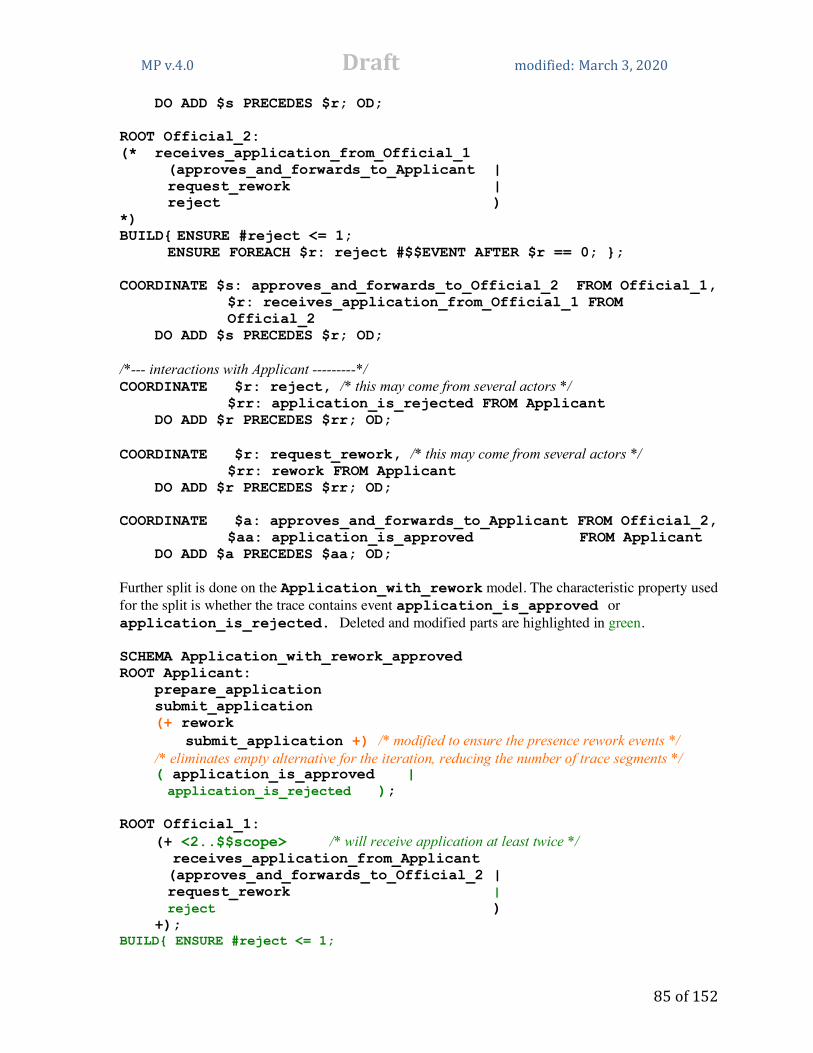
MPv.4.0 Draft modified: March3,2020
85of152
DO ADD $s PRECEDES $r; OD; ROOT Official_2: (* receives_application_from_Official_1
(approves_and_forwards_to_Applicant | request_rework | reject )
*) BUILD{ ENSURE #reject <= 1;
ENSURE FOREACH $r: reject #$$EVENT AFTER $r == 0; }; COORDINATE $s: approves_and_forwards_to_Official_2 FROM Official_1,
$r: receives_application_from_Official_1 FROM Official_2
DO ADD $s PRECEDES $r; OD; /*--- interactions with Applicant ---------*/ COORDINATE $r: reject, /* this may come from several actors */
$rr: application_is_rejected FROM Applicant DO ADD $r PRECEDES $rr; OD; COORDINATE $r: request_rework, /* this may come from several actors */
$rr: rework FROM Applicant DO ADD $r PRECEDES $rr; OD; COORDINATE $a: approves_and_forwards_to_Applicant FROM Official_2,
$aa: application_is_approved FROM Applicant DO ADD $a PRECEDES $aa; OD; Further split is done on the Application_with_rework model. The characteristic property used for the split is whether the trace contains event application_is_approved or application_is_rejected. Deleted and modified parts are highlighted in green. SCHEMA Application_with_rework_approved ROOT Applicant: prepare_application submit_application (+ rework
submit_application +) /* modified to ensure the presence rework events */ /* eliminates empty alternative for the iteration, reducing the number of trace segments */ ( application_is_approved |
application_is_rejected ); ROOT Official_1: (+ <2..$$scope> /* will receive application at least twice */ receives_application_from_Applicant
(approves_and_forwards_to_Official_2 | request_rework | reject )
+); BUILD{ ENSURE #reject <= 1;

MPv.4.0 Draft modified: March3,2020
86of152
ENSURE FOREACH $r: reject #$$EVENT AFTER $r == 0; }; COORDINATE $s: submit_application FROM Applicant, $r: receives_application_from_Applicant FROM Official_1 DO ADD $s PRECEDES $r; OD; ROOT Official_2: (* receives_application_from_Official_1
(approves_and_forwards_to_Applicant | request_rework | reject )
*); BUILD{ ENSURE #reject <= 1;
ENSURE FOREACH $r: reject #$$EVENT AFTER $r == 0; }; COORDINATE $s: approves_and_forwards_to_Official_2 FROM Official_1,
$r: receives_application_from_Official_1 FROM Official_2
DO ADD $s PRECEDES $r; OD; /*--- interactions with Applicant ---------*/ COORDINATE $r: reject, /* this may come from several actors */
$rr: application_is_rejected FROM Applicant DO ADD $r PRECEDES $rr; OD; COORDINATE $r: request_rework, /* this may come from several actors */ $rr: rework FROM Applicant DO ADD $r PRECEDES $rr; OD; COORDINATE $a: approves_and_forwards_to_Applicant FROM Official_2,
$aa: application_is_approved FROM Applicant DO ADD $a PRECEDES $aa; OD; Deletion of several alternatives and COORDINATE significantly reduces the complexity and derivation time for this model. The model for the case when rework was required but application was rejected. Deleted and modified parts are highlighted in green. SCHEMA Application_with_rework_rejected ROOT Applicant: prepare_application submit_application (+ rework
submit_application +) /* modified to ensure the presence of rework events */ /* eliminates empty alternative for the iteration, reducing the number of trace segments */ ( application_is_approved |
application_is_rejected ); ROOT Official_1: (+ receives_application_from_Applicant
(approves_and_forwards_to_Official_2 |

MPv.4.0 Draft modified: March3,2020
87of152
request_rework | reject )
+) BUILD{ ENSURE #reject <= 1;
ENSURE FOREACH $r: reject #$$EVENT AFTER $r == 0; }; COORDINATE $s: submit_application FROM Applicant, $r: receives_application_from_Applicant FROM Official_1 DO ADD $s PRECEDES $r; OD; ROOT Official_2: (* receives_application_from_Official_1
(approves_and_forwards_to_Applicant | request_rework | reject )
*) BUILD{ ENSURE #reject <= 1;
ENSURE FOREACH $r: reject #$$EVENT AFTER $r == 0; }; COORDINATE $s: approves_and_forwards_to_Official_2 FROM Official_1, $r: receives_application_from_Official_1 FROM Official_2 DO ADD $s PRECEDES $r; OD; /*--- interactions with Applicant ---------*/ COORDINATE $r: reject, /* this may come from several actors */
$rr: application_is_rejected FROM Applicant DO ADD $r PRECEDES $rr; OD; COORDINATE $r: request_rework, /* this may come from several actors */
$rr: rework FROM Applicant DO ADD $r PRECEDES $rr; OD; COORDINATE $a: approves_and_forwards_to_Applicant FROM Official_2, $aa: application_is_approved FROM Applicant DO ADD $a PRECEDES $aa; OD; Statistics for these models is assembled in the following table. The measurements have been performed with MP Gryphon running on iMac workstation with 4 GHz Intel Core i7 processor and memory 8 GB. Even for this toy model it appears that the same set of event traces can be obtained in a significantly reduced time after the original model has been split into three sub-models. The main advantage of the split is in the significant reduction of the search space for each model. Scope 1 Scope 2 Scope 3 Scope 4 Scope 5
Original MP model
3 traces in 0.00095 sec.
9 traces in 0.0118 sec.
18 traces in 0.1429sec.
30 traces in 1.2931 sec.
45 traces in 9.52105 sec.
Model no_rework
3 traces in 0.000638 sec.
3 traces in 0.000921 sec.
3 traces in 0.00129 sec.
3 traces in 0.001956 sec.
3 traces in 0.003417 sec.

MPv.4.0 Draft modified: March3,2020
88of152
Model with_rework
No traces 6 traces in 0.010938 sec.
15 traces in 0.1416 sec.
27 traces in 1.16603 sec.
42 traces in 9.13005 sec.
Total for no_rework and with_rework, time ratio
3 traces in 0.000638 sec. 67%
9 traces in 0.011859 sec. 100.3%
18 traces in 0.1429 sec. 99.96%
30 traces in 1.167986 sec. 90%
45 traces in 9.133467 sec. 95.9%
Model with_rework and approved
No traces 2 traces in 0.0026 sec.
5 traces in 0.0339 sec.
9 traces in 0.2929 sec.
14 traces in 2.1593 sec.
Model with_rework and rejected
No traces 4 traces in 0.002946 sec.
10 traces in 0.0263 sec.
18 traces in 0.1333 sec.
28 traces in 0.5926 sec.
Total for no_rework, with_rework and approved, with_rework and rejected time ratio
3 traces in 0.000638 sec. 67%
9 traces in 0.006527 sec. 55.2%
18 traces in 0.0616 sec. 43%
30 traces in 0.428262 sec. 33%
45 traces in 2.755392 sec. 29%
5. DEPENDENCY RELATIONS AND CUSTOM VIEWPOINTS MP schemas and sets of event traces generated from them can be a source for other models with the purpose to answer specific stakeholders’ questions. This aspect of modeling is known as model transformation [Czarnecki, Helsen 2006], where the intention is to preserve consistence and some properties of models obtained from other models. MP schema and event traces generated from it can be considered as related models at different levels of abstraction. While MP schema represents all valid behaviors, and in current MP Firebird implementation is rendered as a plain text, event trace is an abstraction of a particular instance of behavior and is visualized as a graph. The event trace also may represent multiple behaviors, for example, the set of behaviors with the same event structure, but with different timing attributes (since events have time intervals as event’s start and event’s end time values). The concept of dependency appears to be one of the most fundamental in software and system design. Design decisions made at any level of abstraction are driven by the dependency analysis of the model elements. For requirements models dependencies often could be identified and specified as separate items. This implies mostly declarative approach and use of logic formulas to specify those dependencies as properties of the system under development. Architecture views are mostly concerned with dependencies between system components. [Kruchten 1995] presents a discussion of common software architecture views and their purpose. Many of UML/SysML diagrams are intended to render dependencies between system’s parts, like Component Diagrams or Activity Diagrams. Another example is traditional “box-and-arrow” architecture diagram. This kind of diagrams in MP can be obtained by collapsing root events in the event trace as demonstrated in Sec. 2.3. Dependencies can be defined using the basic relations IN and PRECEDES and coordination operations. PRECEDES captures the direct dependency between activities in terms of control or data

MPv.4.0 Draft modified: March3,2020
89of152
flow, and IN relation renders the hierarchical dependency between task and its subtask. Root events in MP can model both components and data items, hence the “box-and-arrow” diagram obtained from the event trace renders the dependencies between these objects. UML Activity Diagram can be considered as an example of view based on PRECEDES relation, and call tree for components as an example based on the IN relation. Current von Neumann computational paradigm, on which most algorithm and system behavior descriptions are based, makes the task of identifying dependencies within the model and reasoning about them difficult and error prone. To a large degree it resists “declarative style” to specify dependencies separately and clearly, and requires expensive processes to extract dependencies from the model, known as “data flow” and “control flow” analyses. In MP descriptions of interactions (coordination) between components are separated from the behavior specification. This level of abstraction makes it easier to find different kinds of dependencies in behavior models. How “declarative” the modeling formalism is may be determined by the way it supports dependency relation handling within the model. The process of transforming MP schema and a set of event traces generated from it into another model can be described as yet another derivation or computation. The result is either a graph (a visualization of the resulting “entity-relation” model - the view), a bar chart, an answer to a query, or a report presenting some statistics about the whole set of behaviors. If the view is derived from a set of event traces, it is called “cumulative” or “global”. Generating event traces (or simple models) from the particular MP schema can be considered as “one-to-many” model transformation. Cumulative model or query is an example of “many-to-one” model transformation. It is worth to mention yet another aspect of building models from MP schemas and event traces. A program in any programming language (and MP schema as well) may contain description of behaviors that will never appear. A trivial example of such phenomenon is a code for component A that contains calls to components B and C, but will never actually call C.
A: if x == x then call B else call C
In most cases architecture diagrams based on the code alone will include component C as a part of system. The set of event traces in MP represents the complete set of “actual” behaviors that are valid within a given scope. When building other models from the event traces this aspect may be of special interest. MP provides means to define custom views (models) that can be extracted from MP schemas and from sets of event traces. These are “entity-relation” models, and may be useful for answering stakeholders’ questions. Examples of questions: “when a component is modified, deleted, or added, what other components may be affected by that change?”, “what particular behaviors of the system may depend on this component?”, “which actors or subsystems in the environment affect or are affected by the behavior of particular component?” Entities in MP views usually represent events or sets of events, where relations typically are dependency relations or user-defined relations to express resource use, command and control hierarchy, topology, and other things of interest. Entities in the view may have attributes, and the dependencies represented by the view may provide a source for architecture complexity metrics and other queries, like cost estimates [Farah-Stapleton et al. 2016].

MPv.4.0 Draft modified: March3,2020
90of152
5.1 Trace views and global views Current MP implementation supports two types of viewpoints: trace views and global views. There are the following views.
• Reports • Graphs • Tables • Bar charts (derived from Tables) • Gantt charts for event trace views implemented as bar charts • Queries • UML activity diagrams.
In addition to event grammar rule definitions and composition operations MP schema may include trace view commands and a GLOBAL section for global view commands at the end of MP source code. It is recommended to perform trace view commands after the trace generation has been completed, i.e. to place these commands at the end of schema’s body after trace derivation commands. The commands in GLOBAL section are performed after the derivation of the whole event trace set is completed. If we assume that $$TRACE event pattern matches the whole event trace as an event, then the GLOBAL can be considered as an event as well, with a structure represented by the following event grammar rule. GLOBAL: {* $$TRACE *}; MP code in the GLOBAL section assumes the described above set of all generated event traces as THIS event. The event instance of GLOBAL may have event attributes as any other event. These attributes can be retrieved and modified in any other part of the MP model: in the BUILD blocks, in the schema’s body (i.e. during the trace derivation), and in the GLOBAL section itself. An attribute of GLOBAL event can be referred as GLOBAL.attribute_name, or, when referred inside the GLOBAL section, just as attribute_name or THIS.attribute_name. See Sec. 5.4 for more. Reports, graphs, tables and charts are accessible in any place of MP code after their declaration, including the GLOBAL section. CLEAR command is used to empty the view object, and SHOW command to output its contents, correspondingly. View objects are constructed with the data extracted from event traces using view_construction_operation(96). Event trace view has two main purposes: to support queries about the event trace and to provide data for debugging MP models (similar to the debugging printouts in common programming). Some of these views can be obtained using regular MP constructs, like COORDINATE loops and SAY clauses. Here are examples. To show the sequence of events in the order of derivation (which is important, because it is the default order for COORDINATE threads), the following MP code may be used either in the context of the whole schema or in a particular BUILD block.

MPv.4.0 Draft modified: March3,2020
91of152
COORDINATE $e: $$EVENT DO SAY($e); OD; This is simple reusable snippet of MP code, which can be inserted in MP model for debugging purposes. If more detailed information about events, for instance, event attribute values is needed, this template can be extended, for example, as COORDINATE $e: $$EVENT
DO SAY($e “ starts at “ $e.start “, ends at “ $e.end );
OD; See Example 23 in Sec. 2.16.2. Sequence of events sorted by their precedence (partial ordering with respect to the PRECEDES relation) can be rendered by the following code. COORDINATE <SORT> $e: $$EVENT
DO SAY($e); OD; In general, SAY clause can be used as a “debugging” printout to provide some data extracted from the current event trace, like
SAY(“number of events A is “ #A) Trace views can enhance event trace documentation and may help to answer some additional questions about the behaviors under consideration. An event trace, which is a visual object by itself, may be accompanied by several view objects. View_construction_operation (96) provides means for creating these objects and forwarding them to the output to supplement the event trace. All view objects (Reports, Graphs, Tables, Bar charts) should be defined before used. This implies that view objects defined in the GLOBAL section cannot be accessed outside of GLOBAL body. If the definition of a view object is placed in the schema’s body before GLOBAL section, it can be used to create and render local (or trace) views, and is available also in the GLOBAL. View objects can be cleared before the beginning of each event trace derivation with CLEAR command and rendered after the trace derivation is complete with SHOW command. If the title of a view object contains expressions, it is refreshed when trace derivation passes through the visual object’s definition. The main premise of the global or architecture view is the availability of the set of event traces generated for the given scope. Data from several event traces can be extracted and assembled into different view objects. The types of view objects used in GLOBAL section are the same as in the trace views. The global_composition_operation(80) is allowed inside the GLOBAL section, but operations that may modify/reject event trace: COORDINATE, SHARE ALL, SHARE, MAP, REJECT, ENSURE, add_relation(34), attribute_assignment(48) for events, and timing_attribute_adjustment(49) are not allowed in GLOBAL section, since it is assumed that all trace derivations should be accomplished by the time when any view_construction_operation(96) is performed in the GLOBAL section and no changes to the set of traces are permitted.

MPv.4.0 Draft modified: March3,2020
92of152
Here are typical patterns for local and global view object design. We’ll use the Report view object as an example. Template 1. Local view objects, or Report attached to a particular event trace. Usually the view object renders data about a complete and valid event trace, hence it makes sense to put view_construction_operation(96) at the very end of schema’s code (but before the GLOBAL section) to ensure that at the time when the view object is constructed the valid trace derivation has been already completed. SCHEMA Example1 … /* rules and composition operations for event trace derivation are here */ … REPORT Local_report {
TITLE (“Report for trace “ trace_id);}; /* Since the report object is global and exists during the whole derivation time, but should be unique for each event trace, the view object should be cleared before construction */ CLEAR Local_report; /* At this point valid event trace derivation has been completed, and is available for the view object construction */ … /* multiple Report construction operations here, like the following */ … SAY(…) => Local_report; … /* Finally, forward it to the output */ SHOW Local_report; Major points:
• Definition should precede any operations with the view object. • If the Report should be constructed for each event trace independently, CLEAR operation is
executed before the construction operations to empty the previous contents. • Construction operations have access to all trace data – events and event attributes, in
particular. • The SHOW command forwards the contents of view object to the output together with the
event trace. Template 2. Global view including data from multiple event traces. For a global view data is collected from many event traces. Since the view object (the Report in this case) is global, it can be retrieved and modified in any place within MP code – both in the schema’s body and in the GLOBAL section. Processing data from several traces requires a loop over event traces. Instead of introducing a special loop operation we can benefit from the fact that such loop already exists – it is the trace derivation process itself. The schema’s body is actually a body of this loop, hence all the data collection for the global view can be arranged within the schema. The data collected from the main loop over traces

MPv.4.0 Draft modified: March3,2020
93of152
may need additional processing, for instance, an additional loop over it, in order to produce the final view. This additional processing can be done in the GLOBAL section. The visual object assembled during the main derivation loop and passed for further processing in the GLOBAL is used as a container. Graph objects are convenient for such purpose, since the Graph can be used as an associative array and node attributes provide a way to store data of different types in these containers. See examples in the following sections for more details. SCHEMA Example2 … /* rules and composition operations for event trace derivation are here */ … REPORT Global_report { }; /* Since the report should accumulate data from each event trace, no CLEAR operation is needed */ /* At this point valid event trace derivation has been completed, and its data is available for the
Report construction operations here, like */ … SAY(…) => Global_report; … GLOBAL … /* additional Report construction operations here, if needed */ … SAY(…) => Global_report; … /* Finally, forward it to the output */ SHOW Global_report; The major points.
• Definition should precede any other operations with the view object. • For global Report CLEAR operation is not needed. • Construction operations placed in the schema’s body have access to all trace data – events
and event attributes. • Construction operations placed in the GLOBAL section have limited access to the trace data.
See global_composition_operation(80). • The SHOW command in the GLOBAL section forwards the contents of view object to the
output after all traces have been derived and processed.
5.2 Reports A report is a sequence of related SAY clauses assembled together to make it easier to read and print. For example, some statistics can be put in a single report: size of event trace, number of events, total duration. Example 39. Local Report within a single trace.
SCHEMA Data_flow ROOT Writer: (* ( working | writing ) *); ROOT File: (+ writing +) (* reading *);

MPv.4.0 Draft modified: March3,2020
94of152
Writer, File SHARE ALL writing; ROOT Reader: (* ( reading | working ) *); Reader, File SHARE ALL reading;
REPORT basic_statistics { TITLE ("scope " $$scope " trace " trace_id);}; /* Clear the contents after a trace derivation has been completed */ CLEAR basic_statistics; /* fill the Report with data from the current event trace */ SAY("#writing= " #writing) => basic_statistics; SAY("#reading= " #reading) => basic_statistics; SAY("#working= " #working) => basic_statistics; /* In order to make it visible together with the event trace, the SHOW command is needed */ SHOW basic_statistics;
Fig. 40. Example of a local report added to a trace.
Example 40. A global report is assembled from the set of all available event traces.
SCHEMA simple_message_flow ROOT Sender: (* send *); ROOT Receiver: (* (receive | does_not_receive) *); COORDINATE $x: send FROM Sender, $y: (receive | does_not_receive) FROM Receiver DO ADD $x PRECEDES $y; OD; REPORT statistics { TITLE ("scope= " $$scope);}; IF #does_not_receive > 0 THEN SAY( "trace " trace_id " sent " #send " received " #receive " ratio " #receive/#send ) => statistics; FI;

MPv.4.0 Draft modified: March3,2020
95of152
/* Since no CLEAR operation is present, the contents of Report is preserved and augmented for each valid event trace */ GLOBAL SAY( "total traces " #$$TRACE) => statistics; /* Global expression #$$TRACE provides number of valid event traces derived for the current scope */ SHOW statistics;
Fig. 41. Example of a global report.
5.3 Graphs Graphs are “entity-relation” models extracted from event traces in order to visualize certain dependencies within the trace. Graph is constructed from nodes and edges connecting the nodes. Usually a node represents some event in the trace and an edge visualizes a dependency between events. Edges can be arrows - directed from one node to another, or undirected lines. Graph may be extended with additional nodes and edges as needed. Node has name (label) attached to it - a string of characters. Graph may have several nodes with the same name. An edge may also have a label (string of characters) attached to it. There cannot be multiple edges with the same label connecting the same pair of nodes. New instance of a graph node is created by node_constructor(101). The string in the node constructor provides node’s name (label), and can be a string of any symbols, not necessary an identifier. Graph processing is encapsulated into the WITHIN block. WITHIN graph_name { … /* different graph_operation(99) and composition_operation(25) go here */ … } All graph operations inside WITHIN body are performed on the same graph with graph_name. Besides of savings on typing, this also helps to separate different graph processing. Let Node$x and Node$y be node variables. The following commands are used to construct/select a node within graph.

MPv.4.0 Draft modified: March3,2020
96of152
Node$x: NEW(“abc”); This command creates a new node instance with a label “abc” and adds it to the current graph indicated in the enclosing WITHIN command. The new node instance is assigned to node variable Node$x. Node$y: LAST(“abc”); This command searches for the latest added instance of a node with label “abc”. If found, it is assigned to the variable Node$y. If an instance of node “abc” has not been found, a new node “abc” is created, added to the current graph indicated in the enclosing WITHIN command (and becomes the LAST instance of a node with label “abc”), and Node$y is assigned it. An edge can be added to the current graph with ADD command. ADD Node$x ARROW(“label”) Node$y; If an arrow with same label already exists between Node$x and Node$y, it will not be duplicated. ADD Node$x LINE(“label”) Node$y; If an edge (arrow or line) with the same label already exists between Node$x and Node$y, it will not be duplicated. If a node variable used in ADD has not been assigned a value, ADD operation has no effect. Node command may be also an argument for ADD. ADD Node$x ARROW(“label”) NEW(“another label”); Note. Somebody could ask: why not to allow combination of node variable assignment and edge adding in the same command? ADD Node$a: NEW (“abc”) LINE(“Label”) Node$b: LAST(“def”); The rationale is to avoid situations like: ADD Node$a: NEW (“abc”) LINE(“Label”) Node$a: LAST(“def”); Graphs can be used as visual objects to render different kinds of dependencies within event traces and in the whole MP model, but can be also used as container data structures (associative arrays) to store and retrieve data for other visualization needs. See Sec. 5.3.1 and Example 48.
Example 41. Graph extracted from a particular event trace (local trace view). We use Car_Race model (Example 6 from Sec. 2.7). Here the MP code for trace view is added to the schema in order to augment each event trace with a graph visualizing the behavior of the car race winner (if there is a winner in the scenario). A graph constructed at the end of schema’s body section and representing a compact event trace of the winner car’s behavior is added to each valid event trace. SCHEMA Car_Race Car: Start (* drive_lap *)
(finish [ winner ] | break); ROOT Cars: {+ Car +}

MPv.4.0 Draft modified: March3,2020
97of152
BUILD{ /* everybody who finishes drives the same number of laps */
ENSURE FOREACH DISJ $c1: Car, $c2: Car (#finish FROM $c1 == 1 AND #finish FROM $c2 == 1 -> #drive_lap FROM $c1 == #drive_lap FROM $c2) AND /* if it breaks, then earlier */ (#finish FROM $c1 == 1 AND #break FROM $c2 == 1 -> #drive_lap FROM $c1 >= #drive_lap FROM $c2); /* there always will be at most one winner */ ENSURE #winner <= 1; /* if at least one car finishes, there should be a winner */
ENSURE #finish > 0 -> #winner > 0; }; /* end Cars */
ROOT Judge: provide_start_signal watch (* finish *); /* end Judge */ COORDINATE $a: provide_start_signal FROM Judge DO COORDINATE $b: Start FROM Cars DO
ADD $a PRECEDES $b; OD;
OD; Cars, Judge SHARE ALL finish; COORDINATE $w: winner DO ENSURE #finish BEFORE $w == 1; OD; /* ======================================================= Here starts the trace view graph construction. Operations are performed after a valid event trace has been successfully derived. =========================================================*/ GRAPH Winner_trace { TITLE( "winner trace " trace_id " for scope " $$scope);}; /* We want to render a graph extracted from each valid event trace,
so the graph is cleared before the trace processing starts. */ CLEAR Winner_trace ; COORDINATE $car_event: Car
SUCH THAT #winner FROM $car_event > 0 DO /* the following WITHIN command provides a context for performing operations on the graph */ WITHIN Winner_trace{ Node$laps: NEW(#drive_lap FROM $car_event " laps"); ADD NEW("Start") ARROW("followed by") Node$laps; ADD Node$laps ARROW("followed by") NEW("winner ");
}; /* end of WITHIN Winner_trace body */ OD; /* end of Car loop */

MPv.4.0 Draft modified: March3,2020
98of152
SHOW Winner_trace;
Fig. 42. Example of a graph added to the event trace view
Example 42. Graph in the GLOBAL view. This global view example is based on Example 35 (MP model of compiler’s front end). It demonstrates how to create a model similar to UML Component Diagram. As [Booch et al. 2000] puts it: ”A component diagram shows the organization and dependencies among a set of components.” In MP behaviors of components and data objects are represented as root and composite events. Dependencies between them can be described as following.
• If one component calls another, the caller event includes callee event (IN relation). • Interactions between components, usually are represented by coordination of events within
the interacting components (presence of PRECEDES between events in different threads). • If a component uses a data object, these events share the access operation event.
The graph representing these dependencies is accumulated from valid event traces. This example is run for scope 1. The scope for some iterations has been increased to provide sufficient number of events to cover all alternatives. The resulting set of traces is representative in a sense that it covers all potential interactions. It justifies claim that the constructed graph is a “UML-like Component Diagram”. The MP code for extracting the Component Diagram model from the set of event traces (or synthesizing a model from a set of simpler models) is reusable. It can be copied/pasted into any MP model to perform the construction of Component Diagram. Of course, it is possible to modify/adjust this code to obtain variety of diagrams. SCHEMA compiler_example ROOT Source_code: (+<1.. $$scope + 1> get_characters unget_some_characters +) ;

MPv.4.0 Draft modified: March3,2020
99of152
/*============= lexical analysis ===============*/ RegExpr_match: match_string [ put_token ] ; Token_recognition: get_characters {+ RegExpr_match +} unget_some_characters BUILD{ /* only one RegExpr_match succeeds */ ENSURE #put_token == 1; }; ROOT Lexer: (+<1..2 * $$scope> Token_recognition +); Source_code, Lexer SHARE ALL get_characters, unget_some_characters; /*================ bottom-up parsing ===============*/ Shift: Push get_token ; Reduce: (*<0..3> Pop *) /* <0..3> is needed to tame the combinatorial explosion for nested iterations */ Push ; ROOT Parser: Push /* push the start non-terminal symbol */ (+ <1..$$scope + 1> /* Perform Shift/Reduce */ get_token [ Shift ] Reduce [ Put_node] +) ( Parsing_complete | Report_syntax_error ) ; /*--- lexer and parser in the interactive mode ---*/ COORDINATE $produce_token: put_token FROM Lexer, $consume_token: get_token FROM Parser DO ADD $produce_token PRECEDES $consume_token; OD; /*==================================================*/ ROOT Stack: (*<2 .. 2 * $$scope + 1 > (Push | Pop) *) /* extended iteration to provide sufficient number of Pop and Push events */
BUILD{ ENSURE FOREACH $x: Pop #Pop BEFORE $x < #Push BEFORE $x; } ;

MPv.4.0 Draft modified: March3,2020
100of152
Parser, Stack SHARE ALL Pop, Push; /*==================================================*/ ROOT Abstract_syntax_tree: (*<0..2 * $$scope> Put_node *); Parser, Abstract_syntax_tree SHARE ALL Put_node; /*======================================= Processing event trace to find dependencies between components. Produces a UML-like Component Diagram. This code is reusable, and can be copied/pasted into any MP model. ========================================*/ GRAPH Diagram { TITLE ("main component interactions");}; COORDINATE $E1: ($$ROOT | $$COMPOSITE) DO COORDINATE $E2: ($$ROOT | $$COMPOSITE) DO WITHIN Diagram{ /* For each valid event trace find all root and composite event instances within the event trace and add them to the graph. */ Node$a: LAST ($E1); Node$b: LAST ($E2); /* LAST option in the node constructors ensures there will be only a single instance of a node in the graph for each root and composite event found in the event trace */ /* If event E1 is IN another event E2, add an arrow “E2 calls E1” */ IF $E1 IN $E2 THEN ADD Node$b ARROW("calls") Node$a; FI; /* We look for interactions between components and data structures. Interactions between components, usually are represented by coordination of events in the interacting components (presence of PRECEDES between events in different threads). Interactions between components and data structures are modeled by shared events, since data structures are usually modeled as a set of operations performed on them. */ IF $E1 != $E2 AND NOT ($E1 IN $E2 OR $E2 IN $E1) AND ( ( EXISTS $E3: $$EVENT
($E3 IN $E1 AND $E3 IN $E2) ) OR ( EXISTS $E3: $$EVENT FROM $E1, $E4: $$EVENT FROM $E2
($E3 PRECEDES $E4) ) ) THEN ADD Node$a LINE("interacts with") Node$b; FI; }; /* end WITHIN Diagram */ OD; OD; /* end of $E1 and $E2 loops */

MPv.4.0 Draft modified: March3,2020
101of152
GLOBAL /* When trace derivation is completed, data from the traces has been accumulated in the graph and
is ready to be shown */ SHOW Diagram;
Fig. 43. Graph produced from GLOBAL
5.3.1 Graphs as container data structures Graphs can be also used as container data structures (associative arrays) to store and retrieve data for other visualization needs. Data may be accumulated for each valid event trace derivation, stored in the Graph, and then processed and output in the GLOBAL section. Graph nodes may have attribute values associated with them. Node attributes have types and initial values similar to the event attributes and are processed using similar operations – attribute assignments and expressions. Nodes don’t have pre-defined timing and trace_id attributes. Example 43. Accumulating and rendering statistics from event traces. Collect and show total number of different event types within the all set of derived event traces. SCHEMA Statistics ROOT A: (* ( a | b) *); ROOT B: (+ c +); GRAPH Stat{
TITLE("Total event count as graph for scope " $$scope);}; ATTRIBUTES { number count;}; COORDINATE $x: $$EVENT DO WITHIN Stat{ Node$e: LAST ($x); /* creates new node with label $x if needed, or finds the existing one */ Node$e.count +:= 1; /* Adjust node attribute value */ ADD Node$e ARROW("in trace") LAST("trace " trace_id); };

MPv.4.0 Draft modified: March3,2020
102of152
OD; GLOBAL /* Render the accumulated statistics as Report. The Stat graph is used as data structure. */ REPORT Total_event_statistics{
TITLE("Total event count as Report"); }; WITHIN Stat{ FOR Node$a DO IF Node$a.count > 0 THEN /* Nodes with “trace” labels have count attribute 0. Create and connect new node with the total count to each event node */ ADD Node$a ARROW("total count") NEW (Node$a.count); /* Graph loop works only with the initial graph contents, new nodes added within the
loop body don’t participate in the iterations. That prevents from infinite looping. */ /* Add to the Report as well. Use the graph as a source of accumulated data. */ SAY(Node$a " event count: " Node$a.count) => Total_event_statistics; FI; OD; /* end FOR */ }; /* end WITHIN Stat */ SHOW Stat; SHOW Total_event_statistics;
Fig. 44. Statistics rendered as a graph and as a report.
5.3.2 Extracting state transition diagram from event traces Example 26 in Sec. 2.18 demonstrates how to model finite automaton behavior in MP and how to extract path view from the event trace. If the set of event traces is representative enough, i.e. covers all possible transitions between states, it is possible to restore the state transition diagram as a global view. The following MP code modifies Example 26 code to add a path graph to each event trace and to construct and render the diagram as a graph in the global view.

MPv.4.0 Draft modified: March3,2020
103of152
Example 44. Adding paths and state transition diagram to the Finite Automaton behavior model. SCHEMA Finite_State_Diagram_with_path ROOT S1_behavior:
Start Start_to_S1 S1 (* (S1_to_S3 | S1_to_S4) S2_to_S1 S1 *) (S1_to_S3 | S1_to_S4); Start_to_S1: empty; S1_to_S3: a; S1_to_S4: (a | b); ROOT S2_behavior: (* S4_to_S2 S2 S2_to_S1 *) S4_to_S2 S2
S2_to_End End; S2_to_S1: b; S2_to_End: empty; S1_behavior, S2_behavior SHARE ALL S2_to_S1; ROOT S3_behavior: (* S1_to_S3 S3 (* S3_to_S3 S3 *) S3_to_S4 *); S3_to_S3: a; S3_to_S4: b; S3_behavior, S1_behavior SHARE ALL S1_to_S3; ROOT S4_behavior: (* S1_to_S4 | S3_to_S4) S4 S4_to_S2 *); S4_to_S2: a; S4_behavior, S1_behavior SHARE ALL S1_to_S4; S4_behavior, S2_behavior SHARE ALL S4_to_S2; S4_behavior, S3_behavior SHARE ALL S3_to_S4; GRAPH Path { TITLE(“Path for the event trace”); }; /* The following coordination extracts all triples State-Symbol-State from the trace and accumulates corresponding nodes/transitions in the Path graph. */ CLEAR Path; /* Path graph is cleared before a new event trace derivation begins. */ WITHIN Path{ COORDINATE /* SORT (plain synchronous coordination) performs topological sort on the selected event set with respect to the transitive closure of PRECEDES (BEFORE relation), and the coordination will follow this ordering. If A BEFORE B holds for events A and B, event A will appear in the sorted sequence before B. This way pairs of states and transitions between them are synchronized. */ <SORT> $state1:(Start | S1 | S2 | S3 | S4), <SORT> $symbol:(a | b | empty),
<SORT> $state2:(S1 | S2 | S3 | S4 | End)

MPv.4.0 Draft modified: March3,2020
104of152
DO Node$s1: LAST ($state1); /* Assigns to the node variable Node$s1 the last instance of node with the event name stored in $state1 in this graph, or creates a new node, if such instance does not yet exist */ Node$s2: NEW ($state2);
/* Creates a new instance of node with name $state2. As a result, nodes with the same label (representing the same state in the diagram) may appear repeatedly in the Path graph. */
ADD Node$s1 ARROW($symbol) Node$s2; OD; /* show Path graph for each event trace */
SHOW Path; }; /* end WITHIN Path */
GRAPH Diagram { TITLE(“State transition diagram”); }; WITHIN Diagram{ /* The following coordination extracts all triples State-Symbol-State from the trace and
accumulates corresponding nodes/transitions in the graph */ COORDINATE <SORT> $state1: (Start | S1 | S2 | S3 | S4), <SORT> $symbol: (a | b | empty),
<SORT> $state2: (S1 | S2 | S3 | S4 | End) DO
ADD LAST ($state1) ARROW($symbol) LAST ($state2); /* this time nodes with the same label will be unique */
OD; }; /* end WITHIN Diagram */
GLOBAL /* After all valid traces have been derived and processed, show the accumulated diagram */ SHOW Diagram;
Fig. 45. Trace view for trace #1 scope 2

MPv.4.0 Draft modified: March3,2020
105of152
Fig. 46. Global view of state transition diagram extracted from the set of event traces for scope 2.
This MP model has to be run for scope at least 2 to cover all state transitions. This kind of views makes it possible to extract UML Statechart-like views from MP system architecture models, providing yet another simple and consistent way to bring together different UML/SysML diagrams based on MP model. In general, such views could be non-deterministic diagrams, where several arrows from the same node may have the same label. Statechart model is a diagram where states represent states of the system and transitions between states are triggered by events. The following slightly adjusted ATM example (Example 4 in Sec. 2.5) demonstrates it. Example 45. Extracting Statechart view from MP model. Behavior of the ATM system is abstracted as a state transition diagram, where the transitions are triggered by Customer’s inputs. Actually, this example as well as the previous one demonstrate yet another MP feature – ability to synthesize complete finite state diagram from a set of execution paths, or model synthesis from a representative set of examples. SCHEMA ATM_withdrawal_with_Statechart_view ROOT Customer: (* insert_card
( identification_succeeds request_withdrawal (get_money | not_sufficient_funds) | identification_fails ) retrieve_card *);
ROOT ATM_system: (* Idle read_card validate_id ( id_successful check_balance ( sufficient_balance dispense_money | unsufficient_balance ) |

MPv.4.0 Draft modified: March3,2020
106of152
id_failed ) *) Idle;
ROOT Data_Base: (* validate_id [ check_balance ] *);
/* Interactions */ Data_Base, ATM_system SHARE ALL validate_id, check_balance;
COORDINATE $x: insert_card FROM Customer,
$y: read_card FROM ATM_system DO ADD $x PRECEDES $y; OD;
COORDINATE $x: request_withdrawal FROM Customer, $y: check_balance FROM ATM_system DO ADD $x PRECEDES $y; OD;
COORDINATE $x: identification_succeeds FROM Customer, $y: id_successful FROM ATM_system DO ADD $y PRECEDES $x; OD;
COORDINATE $x: get_money FROM Customer, $y: dispense_money FROM ATM_system DO ADD $y PRECEDES $x; OD;
COORDINATE $x: not_sufficient_funds FROM Customer, $y: unsufficient_balance FROM ATM_system DO ADD $y PRECEDES $x; OD;
COORDINATE $x: identification_fails FROM Customer, $y: id_failed FROM ATM_system DO ADD $y PRECEDES $x; OD;
GRAPH Diagram{ TITLE(“ATM state transition diagram”); }; /*=======================================
Building a Statechart graph proceeds here =======================================*/ COORDINATE
<CUT_END> $state1: /* these are ATM system’s states, excluding the last one */ (Idle | id_successful | id_failed | sufficient_balance | unsufficient_balance),
$user: /* these are User’s inputs that trigger ATM state transitions */ (insert_card | request_withdrawal | retrieve_card),
<CUT_FRONT> $state2: /* these are ATM system’s states, excluding the first */ ( Idle | id_successful | id_failed |

MPv.4.0 Draft modified: March3,2020
107of152
sufficient_balance | unsufficient_balance) DO WITHIN Diagram{
ADD LAST ($state1) ARROW($user) LAST ($state2);}; OD; GLOBAL
SHOW Diagram; This MP model has to be run for scope at least 2 to cover all state transitions.
Fig. 47. State transition diagram extracted from the event traces for scope 2.
5.4 GLOBAL attributes and GLOBAL queries SAY clauses and Reports can provide additional annotations within the views. Usually these are results of queries about traces. Since the whole set of event traces generated for the given scope is available, it is possible to accumulate calculations over the set of traces and to perform global queries over the set of traces. Example 46. Global query. Model of unreliable message flow (see Example 8). This example demonstrates the use of GLOBAL attributes. Assuming the probability for a message to get lost in transition is 0.2, find probability of a trace with more than 75% successfully received messages. Trace probabilities are calculated as Type 1 (see Sec.2.20.1). Since we are interested only in traces with at least one send event, the (+ ... +) iteration is used. SCHEMA unreliable_message_flow
ROOT Sender: (+ send +); ROOT Receiver: (+ (receive |<<0.2>> does_not_receive) +);
COORDINATE $x: send FROM Sender,
$y: (receive | does_not_receive) FROM Receiver

MPv.4.0 Draft modified: March3,2020
108of152
DO ADD $x PRECEDES $y; OD;
ATTRIBUTES {number trace_unique_id, summary_probability, count; };
GRAPH good_traces{ }; /* Accumulate data about traces of interest within the trace derivation loop. The (+ send +) pattern
helps to avoid situations with #send == 0 */ IF #receive/#send > 0.75 THEN
WITHIN good_traces { Node$x: NEW(trace_id); /* add new data item to the Graph */ Node$x.trace_unique_id := trace_id; }; MARK; /* MARK it to make visible */
FI;
GLOBAL REPORT R{TITLE("Scope " $$scope);};
WITHIN good_traces{
/* FOR-loop over the set of graph’s nodes, see loop_over_graph (105) */ FOR Node$a DO /* Sum up probabilities of traces accumulated in 'good_traces', since traces are statistically independent objects. Notice that trace probability can be estimated only after all valid trace
derivation has been completed, hence it should be postponed to the GLOBAL section, using the #$$TP( ) function to obtain final trace Type 1 probabilities. See global_expression(82) */ summary_probability +:= #$$TP(Node$a.trace_unique_id); count +:= 1; OD; };
SAY("Total " #$$TRACE " traces") => R; SAY("In " count " of traces”
"at least 75% of sent messages have been received") => R;
SAY("At the given scope probability for at least 75%” " messages to pass through is " summary_probability)
=> R; SHOW R;

MPv.4.0 Draft modified: March3,2020
109of152
Fig. 48. Query results produced in the GLOBAL section.
Probability of a “good trace” depends on the scope. This example is small enough to try scopes larger than 5. That can be done using explicit iteration limit (running the whole MP model, for instance, for scope 1), like: ROOT Sender: (+<1..7> send +); ROOT Receiver:(+<1..7> (receive |<<0.2>> does_not_receive)+); Example 47. “Brute force” search over the set of traces for optimal value.
This is a variation of well-known Knapsack Dynamic Programming Problem. In general, it is NP-hard and NP-complete with respect to the number N of items and to the weight limit W. Computational complexity is O(N * W), see https://en.wikipedia.org/wiki/Knapsack_problem This example demonstrates MP template for performing "brute force" search for all optimal solutions within the given scope (certainly not the optimal performance, but acceptable for relatively small N, for this example in particular, it stabilizes at scope 4). SCHEMA Knapsack ATTRIBUTES { number limit, accumulated_total, current_max, A_count, B_count, C_count;}; GLOBAL.limit := 11; /* Set up the weight limit. It is GLOBAL attribute available for each trace derivation. */ ROOT A: (* Item_A *) BUILD{ accumulated_total := #Item_A * 2; }; accumulated_total +:= A.accumulated_total; IF accumulated_total > GLOBAL.limit THEN REJECT; FI; ROOT B: (* Item_B *) BUILD{ accumulated_total := #Item_B * 3; }; accumulated_total +:= B.accumulated_total; IF accumulated_total > GLOBAL.limit THEN REJECT; FI; ROOT C: (* Item_C *) BUILD{ accumulated_total := #Item_C * 5; }; accumulated_total +:= C.accumulated_total;

MPv.4.0 Draft modified: March3,2020
110of152
IF accumulated_total > GLOBAL.limit THEN REJECT; FI; /* if got so far, check whether accumulated_total can be stored as result */ GRAPH candidates{}; IF accumulated_total >= GLOBAL.current_max THEN GLOBAL.current_max := accumulated_total; /* add potential candidate to the list */ WITHIN candidates { Node$a: NEW(trace_id); Node$a.accumulated_total := accumulated_total; Node$a.A_count := #Item_A; Node$a.B_count := #Item_B; Node$a.C_count := #Item_C; SAY("Best result so far: " accumulated_total); }; ELSE REJECT; FI; GLOBAL REPORT best_knapsack {TITLE("Best knapsack");}; SAY("Weight limit " limit) => best_knapsack; SAY("Single item's weight: A= 2 B= 3 C= 5" ) => best_knapsack; SAY("For scope " $$scope " best filling is " current_max)
=> best_knapsack; WITHIN candidates{ FOR Node$x DO IF Node$x.accumulated_total == current_max THEN SAY("Pack " Node$x.A_count " of A, " Node$x.B_count " of B, " Node$x.C_count " of C" ) => best_knapsack; FI; OD; }; SHOW best_knapsack;

MPv.4.0 Draft modified: March3,2020
111of152
Fig. 49. Results for scope 4.
5.5 Tables and charts Data from the event trace can be collected and rendered in the form of table with several columns and visualized as a plain TABLE, or as a BAR CHART. A table contains columns called ‘tabs’, which can hold values of two types: numbers, and strings. Data is stored in the table with add_tuple_command(106). The number of tabs in the add_tuple_command should be the same as number of tabs in table_description(90). BAR CHART is just a view of the corresponding TABLE, hence the only command allowed for Charts is SHOW (but not CLEAR). When using a BAR CHART, one of the tabs defined in the corresponding TABLE should be declared as X_AXIS. The contents of TABLE when visualized via the BAR CHART is sorted by the X_AXIS tab values. Example 48. Assembling statistics about a current trace in a TABLE and rendering it as a bar chart. SCHEMA Example ROOT A: a b c a; TABLE trace_stats { TITLE (“Trace ” trace_id);
TABS string event_name, number total_number;
};
BAR CHART chart_states { TITLE( “Trace ” trace_id “ chart”);
FROM trace_stats; /* contents of the bar chart is derived from the table trace_stats */ X_AXIS event_name;
}; GRAPH event_counters { }; /* This graph container is used as an associative array data structure to accumulate event count for each event in the trace via node attributes */ ATTRIBUTES {number count;};

MPv.4.0 Draft modified: March3,2020
112of152
/* Collect event data and store it in the graph container */ WITHIN event_counters{
COORDINATE $e: $$EVENT /* loop over all events within the trace */ DO Node$a: LAST ($e);
Node$a.count +:=1; /* increment node’s attribute value */ OD; /* Second loop - now fill the table, see loop_over_graph (105) */ FOR Node$n /* variable Node$n is traversing event_counters node set */
DO trace_stats <| /* store tuple in the table trace_stats */
event_name : SAY(Node$n),
/* here (Node$n) is a string_constructor(87) converting node’s name (label) into a character string */
total_number: Node$n.count ; OD;
}; /* end WITHIN */ SHOW trace_stats; SHOW chart_states;/* contents of the related table provides data source for the bar chart */
Fig. 50. View rendered as a table.
Fig. 51. View rendered as a bar chart.
5.5.1 Histograms A histogram is an accurate representation of the distribution of numerical data. To construct a histogram, the first step is to "bin" (or "bucket") the range of values—that is, divide the entire range of values into a series of intervals—and then count how many values fall into each interval (https://en.wikipedia.org/wiki/Histogram). A histogram can be rendered as MP view using a TABLE and a BAR CHART derived from that table. Example 49. Histogram showing number of traces with probabilities within certain intervals. Probability intervals are shown as [a..b), which means a <= p < b.

MPv.4.0 Draft modified: March3,2020
113of152
SCHEMA Example ROOT A: (<<0.2>> a1 | <<0.3>> a2 | (* a3 *)); ATTRIBUTES { number count; }; GLOBAL /* This GRAPH is used as a container to collect data about valid trace probabilities. The following MP code can be reused for any MP model just by Copy/Paste. */ GRAPH Data { }; WITHIN Data{ /* numerical_loop_header(40) is used to perform required interval calculations. */ FOR Num$t: [1.. #$$TRACE] STEP 1 DO FOR Num$n: [0 .. 1] STEP 0.1 DO Node$x: LAST("[" Num$n ".." Num$n + 0.1 ")"); /* p - pre-defined trace probability attribute */ IF ( Num$n <= #$$TP(Num$t) AND #$$TP(Num$t) < Num$n + 0.1) OR
/* special case when the only single trace with probability 1 exists */ ( #$$TRACE == 1 AND Num$n == 0.9) THEN Node$x.count +:= 1; FI; OD; OD; }; /* end of WITHIN Data */ TABLE probability_histogram {
TABS string probability_interval, number trace_count; }; BAR CHART probability_chart { TITLE("Trace probabilities"); FROM probability_histogram; X_AXIS probability_interval; }; WITHIN Data{ FOR Node$n DO probability_histogram <| probability_interval: SAY(Node$n), trace_count: Node$n.count; OD; }; SHOW probability_chart SORT; /* The contents of the chart is sorted by X_AXIS string values, since the order of adding rows to the TABLE may be arbitrary */

MPv.4.0 Draft modified: March3,2020
114of152
Fig. 52. Example of a histogram produced in the GLOBAL view
5.5.2 Gantt charts Since events in the trace can have non-zero timing attributes, it may be interesting to visualize duration and overlapping in time for all or some of them. Such visualization usually is called Gantt chart (see https://en.wikipedia.org/wiki/Gantt_chart ). Since timing attributes are time intervals, there are several options to do it – using the earliest, latest, or average start and end times. This view can be implemented in MP with BAR CHART. In this example the ROTATE option is used with the BAR CHART to rotate the whole picture to 90 degrees. Example 50. Gantt chart. Task: for each event in the trace show the earliest event’s start time and the longest duration. SCHEMA S ROOT A: a1 a2; ROOT B: b1 a2 b2; A, B SHARE ALL a2; COORDINATE $a1: a1, $a2: a2, $b1: b1, $b2: b2 DO SET $a1.duration AT LEAST 3; SET $a2.duration AT LEAST 5; SET $b1.duration AT LEAST 1; SET $b2.duration AT LEAST 2; OD; /* The following code can be reused for any MP model by Copy/Paste. */ TABLE gantt_1{ TABS string event_name, number start_time, number duration_time;}; BAR CHART gantt_2 { TITLE(“Example of Gantt Chart”); FROM gantt_1; X_AXIS event_name; ROTATE; /* to place the X_AXIS vertical */}; COORDINATE $e: $$EVENT DO /* add this event to the Table */ gantt_1 <| event_name: SAY($e), start_time: $e.start.smallest, duration_time: $e.duration.largest ; OD;

MPv.4.0 Draft modified: March3,2020
115of152
SHOW gantt_2;
Fig. 53. Trace generated for the Example 50.
Fig. 54. Example of a Gantt chart.
5.6 UML activity diagrams UML activity diagrams can provide yet another view on the dependencies of events within a single component (root or composite event in MP). Not all MP constructs for behavior specification can be captured by UML/SysML activity diagram notation. In particular, behavior constraints, like ENSURE and coordination could be only included in UML activity diagrams as comments. Concurrency concept in UML/SysML and its relation with control flow is vague and sometimes hard to explain. Such MP constructs as {* A *} cannot be directly translated into activity diagrams, and abbreviation of the set iterations for a given scope is used to address this issue (see Fig. 57). Activity diagram view extracted from MP code is just a superficial approximation of the behavior set specified in MP and cannot be used for a serious analysis of MP model, but just as a visual view. Nevertheless, some users may be interested in extracting activity diagrams from MP model. It should be noticed that MP enforces better structured control flow (no unrestricted goto's) and has simple modularization mechanism (composite events) for scalability and readability. All that helps to avoid some of the issues inherent in UML/SysML activity diagrams.

MPv.4.0 Draft modified: March3,2020
116of152
Here are templates for converting MP code into activity diagram notation. The resulting activity diagrams are well-structured while the MP code provides precise interpretation of the rendered behaviors.
Fig. 55. Mapping some MP constructs in activity diagram notation.
Fig. 56. Mapping optional and iterative MP constructs in activity diagram notation.
UML/SysML Activity Diagram notation does not support concurrency description with variable thread numbers. Here we have introduced a bar label with number of the concurrent threads. This number depends on the scope given for the MP model.
Fig. 57. Mapping iterative MP set constructs in activity diagram notation.

MPv.4.0 Draft modified: March3,2020
117of152
Example 51. Activity diagram of a root event. SCHEMA S ROOT A: a1
[a2] { a3, a4, a5 } a6 ( a7 | a8 )
; SHOW ACTIVITY DIAGRAM A;
Fig. 58. Example of Activity Diagram view.
6. MP LANGUAGE CONSTRUCTS
6.1 Lexics 'ttt' - terminal string Id - identifier, sequence of upper or lower case letters, digits, and underscore, starting with
a letter. Identifiers are case-sensitive. Current implementation limits identifier’s length to 80 characters.
float_constant – float constant has decimal point, like 24.5. It may have unary minus preceding it, like -24.5. Use of exponent also is allowed, like 24E2 or 24.5E-2 integer_constant – integer constant should be decimal integer, like 25, and may have unary minus preceding it, like -25 ”characters” – string constant with zero or more characters, which may be any printable ASCII characters, except escaped characters, like \n. Current implementation limits string constant length to 80 characters. comments - /* text */

MPv.4.0 Draft modified: March3,2020
118of152
Spaces, eol, and tabs in MP code are not syntactically significant, except when separating keywords and/or identifiers.
6.2 Extended BNF notation for MP syntax P, P1, and P2 stand for grammar’s terminals, non-terminals, or groups, where E stands for a terminal symbol. (* P *) – P repeated zero or more times (+ P +) – P repeated one or more times (* P * E) – P repeated zero or more times, separated by E (+ P + E) – P repeated one or more times, separated by E ( P1 | P2 ) - alternative (may have one or more alternatives) [P] - optional P
6.3 Event grammar rules (1) schema: 'SCHEMA' schema_name(2) (* ( rule(3) | composition_operation(25) | attribute_declarations(50) | VIEW_description(83)(84) ) ‘;’ *) [ global_view(79) ] ; Derivation of the schema’s trace proceeds top-down and from the left to right. Composition and view operations are performed following the order of derivation, immediately after the root derivation and composition operations appearing in the schema before them were completed, and hence may speed up the trace derivation by rejecting the previously derived invalid root traces before proceeding with the next roots. Placing view_construction_operation(96) in GLOBAL section ensures that it will be performed only when all valid event trace derivation has been completed.
(2) schema_name: Id -- schema’s name is an identifier ; (3) rule: ( 'ROOT' root_name(4) | event_name(7) ) ':' pattern_list(5) [ Build_block(54)] ; Absence of the ROOT keyword yields a composite event declaration. Operations in BUILD blocks defined for roots and composites are performed each time when the trace derivation for that root or composite is accomplished. These are local “crisscrossing” derivation rules, which can add more relations within the root or composite trace. Notice the absence of semicolon before BUILD block.

MPv.4.0 Draft modified: March3,2020
119of152
(4) root_name: Id -- root name is an identifier ;
6.4 Event patterns (5) pattern_list: (* pattern_unit(6) *) ; (6) pattern_unit: ( event_name(7) | alternative(8) | iterator(10) | iterator_plus(16) | set(17) | set_iterator(18) | set_iterator_plus(19) | optional(20) ) ; No recursion (direct or indirect) in composite event grammar rules is allowed.
(7) event_name: Id ; Event name is an identifier, atomic or composite event type name. (8) alternative: '(' (+ [ probability(9) ] pattern_list(5) +'|') ')' ; The alternative event pattern is comprised of two or more alternatives. The ‘probability’ option is the probability to select the alternative in the random trace generation mode, each selection is independent from the previous history. Empty option for pattern_list is needed to balance probabilities assignment, e.g. in ( A | B | ) empty alternative has probability 0.3333333, but in [(A|B)] it will have probability 0.5. [A] is equivalent to (A| ) Alternative pattern with a probability and a single branch (<<p>> A) is equivalent to the optional(20) pattern [<<p>> A], or to the (<<p>> A | ) Alternative pattern ( A ) has default probability 1.0 and is equivalent to the pattern A. (9) probability: '<<' float_number(58) '>>' ; Probability for selecting an alternative in the random trace generation process. Current MP implementation does not have Monte Carlo simulation option for random trace generation, but, nevertheless, the probability of a trace can be calculated. See Example 30. float_number should be in the range 0.0 – 1.0

MPv.4.0 Draft modified: March3,2020
120of152
Sum of probabilities within the alternative pattern unit should be 1.0 Probabilities not provided explicitly, are prorated evenly to supplement the total sum to 1.0 (10) iterator: '(*' [ iteration_scope(11)] pattern_list(5) '*)' ; Probability of selecting particular number of iterations in the derivation process can be specified using alternative event pattern with probabilities attached to the branches of alternative, like
( <<0.7>> (*<1> E *) | <<0.3>> (*<2> E *) ) (11) iteration_scope: '<' [ scope_expression(12) '..' ] scope_expression(12) '>' ; The value of scope_expression should be non-negative integer. The default for (* … *) iteration is < 0 .. $$scope >. Iteration scope <min .. max> implies that during trace derivation the number of iterations will proceed from min to max; < n > is the same as <n .. n>. The scope_expressions(12) may be helpful to ensure that the number of iterations is sufficient to produce enough events to coordinate with multiple sources (see Publish_Subscribe example in Sec. 2.8, the iteration in the Publisher root). (12) scope_expression: scope_expr_additive_elt(13) (* ('+' | '-') scope_expr_additive_elt(13) *) ; (13) scope_expr_additive_elt: scope_expr_term(14) (* ('*' | '/') scope_expr_term(14) *) ; (14) scope_expr_term: ( integer_number(57) | '(' scope_expression(12) ')' | scope_metavariable(15) ) ; (15) scope_metavariable: '$$scope' ; The value of $$scope is set up before the trace derivation begins, and hence is available for use in iteration_scope(11), reshuffling_unit(33), and in expression(67) in MP code. (16) iterator_plus: '(+' [ iteration_scope(11)] pattern_list(5)'+)' ; The default for iteration scope is < 1 .. $$scope >, the lower limit can not be less than 1; (17) set: '{' (* pattern_list(5) * ',') '}'

MPv.4.0 Draft modified: March3,2020
121of152
; set requires only IN relation between the set and its elements; (18) set_iterator: '{*' [ iteration_scope(11)] pattern_list(5) '*}' ; The default for iteration scope is < 0 .. $$scope >; < n > is the same as <n .. n> (19) set_iterator_plus: '{+' [ iteration_scope(11)] pattern_list(5) '+}' ; The default for iteration scope is < 1 .. $$scope >, the lower limit can not be less than 1 (20) optional: '[' [ probability(9)] pattern_list(5)']' ; The default probability is 0.5
6.5 Navigation directions (21) navigation_direction:
relational_expression(22) ; Navigation within event traces is one of the main MP features, and uses binary relations between event instances - basic (IN and PRECEDES), or user-defined. This “Time Machine” is deployed in bool_expr3(63), and may be used in quantified_bool_expr(64), and special_function(73) explicitly, or via thread(24) with SUCH THAT clause in coordination operations containing asynchronous_source(29) or coordination_source(30). (22) relational_expression:
( ‘IN’ | ‘PRECEDES’ | ‘ENCLOSING’ | ‘FROM’ | ‘CONTAINS’ | ‘FOLLOWS’ | ‘BEFORE’ | ‘AFTER’ | relation_name(55) | user_defined_relation(56) | ‘(’ relational_expression ‘)’ | ‘~’ relational_expression | ‘^’ relational_expression ) For a binary relation R (basic or user-defined), ~R stands for the reverse R, and ^R for the transitive closure (the relation that contains R and is transitive). Operations ~ and ^ are right-associative. Note that ^(~R) is equivalent to ~(^R). See Sec.7.2 for more details. For the convenience of navigation within the trace, besides of the basic relations IN and PRECEDES, there are additional relation names for reversed and transitive closures of basic relations: ENCLOSING is a reverse of IN, or ~IN, FROM is a transitive closure of IN, or ^IN CONTAINS is a reverse of FROM, or ~FROM, or ~(^IN), FOLLOWS is a reverse of PRECEDES, or ~PRECEDES,

MPv.4.0 Draft modified: March3,2020
122of152
BEFORE is a transitive closure of PRECEDES, or ^PRECEDES, AFTER is a reverse of BEFORE, or ~BEFORE, or ~(^PRECEDES). Sec.7.1 provides ten axioms specifying properties of basic relations. This implies that valid event trace always is a directed acyclic graph. The following picture illustrates possible navigation relations between events a and b. The REL stands for a user-defined binary relation name in a REL b.
Fig. 59. Navigation directions for basic and user-defined relations.
(23) variable: $Id ; MP variable is an identifier preceded by ‘$’, like $a, and can be assigned an event instance as a value. It can be used in several MP constructs: thread(24), shared_composition(26), coordination_source(30), add_relation(34), map_unit(38), bool_expr3(63), event_instance(71), special_function(73). (24) thread: variable(23) ‘:’ selection_pattern(35) [‘FROM’ event_instance(71) ] [‘SUCH’ ‘THAT’ bool_expr(60)] ; The thread is kind of a set comprehension, and specifies a set of events selected by applying selection pattern and selection conditions (SUCH THAT). If an event instance has been shared with other root or composite event, only a single instance of shared event will be included in the thread.

MPv.4.0 Draft modified: March3,2020
123of152
Threads may be used as sources of events in coordination_source(30), in asynchronous_source(29), in the # special_function(73). The scope of variable bound to the selection_pattern depends on the operation/expression, which deploys the thread. Search for events matching the selection_pattern is performed within the set determined by the FROM clause. Absence of the FROM clause is equivalent to FROM THIS, where THIS refers to the root or composite event in the BUILD block of which the thread appears, or to the whole schema, if the thread appears in the schema’s body. If the thread appears in the BUILD block of a root or composite event, root_name in the FROM clause is not allowed. Root names as event_instance in FROM may be used in schema’s body. Example. Assume that the selection is done from the schema’s trace segment (FROM THIS), where A, B are root events. SUCH THAT clause makes it possible to assemble a thread from different events and from several sources. It can be used to express set union and set intersection for event sets. The following thread is a union of two sets - events of type a from A, and events of type b from B: $x: (a | b) SUCH THAT ( $x FROM A AND $x IS a) OR ( $x FROM B AND $x IS b) If two events within the search domain are shared as a result of previous coordination with SHARE or MAP, only one instance (which was added to the trace first) will be included in the thread.
6.6 Composition operations (25) composition_operation: ( shared_composition(26) | asynchronous_coordinate_composition(27) | coordinate_composition(28) | MAP_composition(37) | conditional_composition(42) | simple_action(43) | FOR_loop(39) ) ; Composition operations act like “crisscrossing” derivation rules that may add new events and basic relations to the trace under derivation. (26) shared_composition: (+ ( root_name(4)| variable(23) ) + ',') 'SHARE' 'ALL' (+ event_name(7) + ',') ; Clause root_name is not allowed if a composition operation appears in the BUILD block of a root or composite event, it may be used in schema’s body only.
The sharing composition operation is performed on the default sequences of events. It does not have explicit reshuffling option, but if needed, reshuffling for SHARE ALL can be done by combining coordinate composition operation (28) or (27) and SHARE_clause(44), as demonstrated in the example for SHARE_clause(44). Events to be shared are of the same type (have the same event type name) and hence have the same event attribute signature. If the values of corresponding event attributes are not equal, the SHARE

MPv.4.0 Draft modified: March3,2020
124of152
ALL operation fails, and the failure is propagated to the enclosing BUILD block or schema. There is one exception. Time attributes depend on basic relations and are recalculated automatically each time when basic relations of an event are adjusted in the derivation process. When a pair of events is SHAREd, their relations (basic and user-defined) are merged, and this may trigger time attribute recalculation. (27) asynchronous_coordinate_composition: ‘COORDINATE’ (+
(coordination_source(30) | asynchronous_source(29) )
+ ‘,’) ‘DO’ (* composition_operation(25) ‘;’ *) ‘OD’ ; Asynchronous coordinate composition should contain at least one asynchronous_source(29) and may produce several different event traces, one for each permutation in each asynchronous source. It contributes to the trace derivation process in a similar way as the alternative(8) pattern does. Asynchronous coordinate composition cannot be nested into another asynchronous_coordinate_composition(27), coordinate_composition(28), or conditional_composition(42). It may contain several asynchronous sources(29) and/or coordination sources(30), and may contain other composition operations (25) in the DO/OD body (including coordinate compositions(28), but except another asynchronous_coordinate_composition. (28) coordinate_composition: ‘COORDINATE’ (+ coordination_source(30) + ‘,’) ‘DO’ (* composition_operation(25) ‘;’ *) ‘OD’ ; COORDINATE is essentially a loop over one or more event sets of equal size (coordination sources). It starts with the tuple of first event from each coordination source followed by performing the DO/OD on that tuple, then a tuple of second events in each coordination source is selected and DO/OD is performed again, and so on. The composition operations enclosed within DO/OD are performed for each tuple of events selected from the coordination sources. By default the order of event selection follows the order of events in the trace generated during the derivation process. In most cases this will be sufficient. The coordination_source(30) may provide an option for event reshuffling to change the order of coordination for the selected sets. Variables bound to the selection patterns within coordination sources of the composition are visible in the DO/OD body of this composition (including nested threads), but not in other threads

MPv.4.0 Draft modified: March3,2020
125of152
coordinated by this coordination composition. If all coordination sources yield empty sets, no operations in the DO/OD body will be performed but the coordination operation will still succeed. (29) asynchronous_source:
(‘<!>’ | ‘<!CHAIN>) thread(24) ; <!> means asynchronous coordination, and may produce several event sets, each of which will be tried by enclosing COORDINATE. The traces resulting from the coordination operation will include all permutations of events from the coordination source. This assumes that other constraints, like partial ordering axioms (Sec. 7.1) are satisfied. Each valid permutation yields an instance of a resulting trace for the composite event, root, or schema deploying this composition. If there are N events in the default sequence, <!> will produce 1 * 2 * 3 * … * (N-1) * N = N! sequences. Asynchronous coordination may cause dramatic increase in the number of generated traces and the generation time. See examples in Sec. 2.8 and 2.15. <!CHAIN> is similar to <!>, it produces all permutations of events from the coordination source. In addition it will add the PRECEDES relation between each pair of adjacent events in the resulting sequence. If the insertion of PRECEDES violates partial ordering axioms (Sec. 7.1), the generated permutation is rejected, coordination backtracks and proceeds with the next permutation. (30) coordination_source: [ event_reshuffling_option(31) ] thread(24) ; (31) event_reshuffling_option:
( ‘!>>’ | ‘<’ sequence_of_reshufflings(32) ‘>’ ) ; The default for event selection in the coordination source within COORDINATE preserves the order of events generated during the derivation process. The default means that the thread will be used “as is”. The reshuffling operations may be applied to the default set before the coordination to rearrange events within the selected set. Strict synchronous coordination !>> sorts selected event set with respect to the transitive closure of PRECEDES (BEFORE relation), and the coordination will follow this ordering. If event set cannot be totally ordered, the coordination operation fails, and the trace derivation backtracks.
Event reshuffling may be useful when we need to control the coordination order, but in most cases the default option will be sufficient. The same consideration applies also to SHARE ALL composition operation. It does not have explicit reshuffling option, but if needed, reshuffling for SHARE ALL can be obtained by combining COORDINATE and SHARE clause, as demonstrated in the example for SHARE_clause(44). (32) sequence_of_reshufflings: (+ reshuffling_unit(33) +) ;
(33) reshuffling_unit:

MPv.4.0 Draft modified: March3,2020
126of152
( ( ‘SORT’ | ‘REVERSE’ | ‘SHIFT_RIGHT’ | ‘SHIFT_LEFT’ | ‘CUT_FRONT’ | ‘CUT_END’ | ‘FIRST’ | ‘LAST’ ) [‘(‘scope_expression(12) ‘)’] | ‘(*’ [‘<’ scope_expression(12) ‘>’] sequence_of_reshufflings(32) ‘*)’ ) ; SORT (plain synchronous coordination) performs topological sort on the selected event set with respect to the transitive closure of PRECEDES (BEFORE relation), and the coordination will follow this ordering. This means that if A BEFORE B holds for events A and B, event A will appear in the sorted sequence before B. If the result does not yield a total ordering, the coordination will still proceed. SORT(N) applies sorting N times, which of course does not make too much sense, and is equivalent to SORT(1) or just to the plain SORT.
REVERSE produces the reversed sequence. For example, it may be useful when modeling Last-In-First-Out (or LIFO) behaviors. REVERSE(N) will apply REVERSE N times, where REVERSE(N + 2) is equivalent to REVERSE(N). SHIFT_RIGHT(N) takes the last N events from the default sequence and moves them to the beginning (circular shift N to the right). This may be useful for coordinating event with its neighbors. SHIFT_RIGHT is equivalent to SHIFT_RIGHT(1). SHIFT_LEFT(N) takes the first N events from the default sequence and moves them to the end (circular shift N to the left). See the Ring example in Sec. 2.14. SHIFT_LEFT is equivalent to SHIFT_LEFT(1). The reshuffling operations below have similar constraint: if the selected event sequence contains less than N elements, the enclosing coordination operation fails, and the trace derivation backtracks. The same happens if any of these operations are applied to the empty set.
CUT_FRONT(N) deletes N events from the front of selected sequence. CUT_FRONT is equivalent to CUT_FRONT(1). CUT_END(N) deletes N events from the end of selected sequence. CUT_END is equivalent to CUT_END(1). FIRST(N) returns the first N elements from the sequence and cuts the rest. FIRST is equivalent to FIRST(1). LAST(N) returns the last N elements from the sequence and cuts the rest. LAST is equivalent to LAST(1). (* <N> sequence *) will repeat the sequence of reshuffling operations N times. Please notice that symbols ‘<’ and ‘>’ are used to enclose both sequence of reshuffling units and the iteration number (which may be an expression). Sequence of reshuffling operations is performed from left to right. Reshuffling operations provide certain flexibility to shape the set of events selected for coordination.

MPv.4.0 Draft modified: March3,2020
127of152
Operations CUT, FIRST, and LAST may change size of the selected set. Checking for the equal size of coordination sources within the COORDINATE is performed after the reshuffling for each source is accomplished. Please notice that “!>>” and “<!>” are not allowed within the reshuffling_unit. Examples of event reshuffling options composed from simple reshuffling operations.
• Two shifts left can be described as <SHIFT_LEFT SHIFT_LEFT> or as < (* <2> SHIFT_LEFT *) > • <SHIFT_RIGHT> is equivalent to <REVERSE SHIFT_LEFT REVERSE> • Event set in descending topological order: <SORT REVERSE>
(34) add_relation:
‘ADD’ (+
( event_instance(71) | SAY_clause(47) ) (‘IN’ | ‘PRECEDES’ | user_defined_relation(56))
( event_instance(71) | SAY_clause(47) ) +‘,’) ; If add_relation operation appears in the BUILD block of a root or composite event, root_name in event_instance is not allowed. It may be used in schema’s body only. Notice that relations ENCLOSING, FROM, CONTAINS, FOLLOWS, BEFORE, and AFTER cannot be added, and can be used in bool_expr(63) expressions only. SAY_clause is a special case of composition operation that creates a new instance M of message event (visualized in the Firebird event trace as a “dog ear” box) and initializes its text attribute with the message text. SAY operation by default always performs ADD M IN THIS operation, and the “dog ear” box will be associated with the schema or with the root/composite event in which BUILD block it appears. By placing SAY as argument in ADD it becomes possible to bind the message event with some other event with IN, PRECEDES, or user-defined relation, thus providing more focused visualization of the message (see Example 11). User-defined binary relations can be used in the navigation_direction(21) via relational_expression(22). ADD operation is not allowed within global_view(79) section. (35) selection_pattern: ( Single_event_selection(36) | ‘(‘ (+ Single_event_selection(36) + ‘|’) ‘)’ ) ; Selection_pattern is used in coordinate_composition(28) via thread(24), quantified_bool_expr(64), and in special_function(73) (36) Single_event_selection:
( event_name(7) | ‘$$EVENT’ |

MPv.4.0 Draft modified: March3,2020
128of152
‘$$ROOT’ | ‘$$COMPOSITE’ | ‘$$ATOM’ )
; The meta-symbol $$EVENT matches any event type, including the whole trace event (which always is present in the generated trace). This event pattern could be used with the ENSURE operation for user-defined relation properties, similar to the examples in Sec. 7.1, or to provide the total number of events within another event E, like #$$EVENT FROM E. #$$EVENT will yield the total number of events within THIS. $$ROOT matches root events only, $$COMPOSITE matches composite events (but not root events), and $$ATOM matches atomic events only. (37) map_composition: (+ ‘MAP’ map_unit(38) ‘ON’ map_unit(38) +‘,’) ; The purpose of the map construct is to implement behavior reuse. MAP A ON B updates the context and structure of event B by adding B to all relations in which A participates - IN, PRECEDES, and user-defined relations (56). MAP does not affect event attributes, except time attributes, which depend on basic relations and are recalculated automatically each time when basic relations of an event are adjusted in the derivation process. If REL is basic or user-defined relation, then MAP A ON B is equivalent to performing the following operations for all REL. COORDINATE $x: $$EVENT DO IF $x REL A THEN ADD $x REL B; FI; IF A REL $x THEN ADD B REL $x; FI; OD; Suppose that original behaviors of A and B are specified as A: pattern1; B: pattern2; Because all IN relations in which A participates are copied to B, the behavior of B after MAP A ON B can be described as a set of original behaviors, i.e. B: { pattern1, pattern2 }; Thus, MAP is a shortcut for a whole group of coordination operations, which otherwise should be written separately. After MAP A ON B, B also inherits all behaviors in which A participates (the whole context of A). The difference with SHARE_clause(44) being that the instance of A and its relations still remain in the trace unchanged. (38) map_unit: ( root_name(4) | variable(23) ) ; If map composition operation appears in the BUILD block of a root or composite event, root_name is not allowed. It may be used in the schema’s body only.

MPv.4.0 Draft modified: March3,2020
129of152
(39) FOR_loop: ‘FOR’ numerical_loop_header(40) ‘DO’
(* composition_operation(25) ‘;’ *) ‘OD’
; (40) numerical_loop_header:
numeric_variable(41) ‘:’ interval_constructor(71) ‘STEP’ ( integer_number(57) | float_number(58) )
; STEP number should be non-zero positive value. Numerical loops may be useful for table and chart construction. (41) numeric_variable: ‘Num$’ Id ; Numeric variable is an identifier with a prefix Num$. It is assigned a numeric value in the numerical loop header(40). It cannot be reassigned. This variable is available and can be used in expressions within the DO-OD loop body where it has been defined. (42) conditional_composition: ‘IF’ bool_expr(60) ‘THEN’ (* composition_operation(25) ‘;’ *) [‘ELSE’ (* composition_operation(25) ‘;’ *) ] ‘FI’ ; This control structure provides additional conveniences for trace generation, including context condition check for filtering traces, trace annotation with messages, assertion checking. See also ensure_request(45) and assertion_check(46), which are abbreviations based on the use of conditional_composition.
(43) simple_action: ( ‘REJECT’ | ‘MARK’ | add_relation(34) | SHARE_clause(44) | ensure_request(45) | assertion_check(46) | view_construction_operation(96) | SAY_clause(47) | attribute_assignment(48) | timing_attribute_adjustment(49) ) ; REJECT terminates the derivation for the current event trace or root/composite segment, and the generator proceeds to the next instance. This operation may be useful for early pruning in the derivation process. Typical use is demonstrated by the ensure_request(45). Sometimes you may just

MPv.4.0 Draft modified: March3,2020
130of152
want to temporarily delete some traces from the browsing list. MARK can be performed in a BUILD block of root or composite, or in schema’s body, and will ensure that the complete trace under derivation will be highlighted to make it distinct in the graph window navigation list. To MARK a trace in the process of model testing/debugging may be useful in order to indicate that it contains something of interest (more details could be provided in the messages produced by SAY_clause(47) and attached to the event boxes in the trace graph). For instance, MARK is used to highlight assertion counterexamples in assertion_check(46). MARK performed in any BUILD block is propagated during the derivation, and traces including a MARKed root/composite segment also become MARKed, up to the top trace. The Firebird’s graph window navigation list contains all MARKed and un-MARKed traces for which the derivation within the scope has been completed.
(44) SHARE_clause: ‘SHARE’ variable(23) variable(23) ; This operation merges instances of two events. If event types are distinct, the operation fails, and the failure is propagated to the enclosing BUILD block or schema. If both are atomic events of the same type, operation may succeed and event instances are merged into a single event instance inheriting all relations from each. For composite events both arguments should have the same structure of events inside them. Yet another necessary condition for successful event sharing is the same event attribute values at the derivation moment when the SHARE_clause is performed, otherwise the operation fails. There is one exception. Time attributes depend on basic relations and are recalculated automatically each time when basic relations of an event are adjusted in the derivation process. When a pair of events is SHAREd, their relations (basic and user-defined) are merged, and this may trigger time attribute recalculation. The shared_composition(26) operation A, B SHARE ALL x; can be expressed in terms of coordinate_composition(28) and SHARE_clause, as COORDINATE $a: x FROM A, $b: x FROM B DO SHARE $a $b; OD; The coordination operation above is applied to the default event sets. In most cases it is sufficient. With the event_reshuffling_option(31) in the COORDINATE it is possible to SHARE all permutations of event sequences, like in the following example. COORDINATE $a: x FROM A, <!> $b: x FROM B DO SHARE $a $b; OD; (45) ensure_request: ‘ENSURE’ bool_expr(60) ;

MPv.4.0 Draft modified: March3,2020
131of152
ENSURE A; is an abbreviation for IF A THEN /* continue derivation */ ELSE REJECT; FI; When used in the Build_block(54) of a composite event or root, or in the schema’s body(1) this action filters the trace derivation by applying context conditions to the already derived segment of event trace. (46) assertion_check: ‘CHECK’ bool_expr(60) ‘ONFAIL’ SAY_clause(47) ; CHECK A ONFAIL SAY(“Message”); is an abbreviation for IF A THEN /* continue derivation */ ELSE SAY(“Message”); MARK; FI; Assertion checking may be included in the Build_block(54) or in the schema’s body(1), usually for model’s testing/debugging. If the trace segment under derivation violates the assertion, an instance of the trace including this segment will be MARKed (highlighted) and available for browsing with a message explaining the cause. If the property described by the assertion should be always satisfied, it is better to include it as ENSURE construct. CHECK is the most common pattern for assertion checking, providing a message associated with a root, composite event, or the whole trace. More detailed assertion checking for advanced model testing/debugging with message boxes bound to particular events in the trace can be achieved by using a combination of COORDINATE, ADD and SAY constructs (see Example 9).
(47) SAY_clause: ‘SAY’ string_constructor(87) ; SAY_clause generates messages (events) that are visible in the event trace graph as distinct boxes. It may be used to provide trace annotations. By default the message event is under IN relation with the root/composite or schema event, depending on where (in the BUILD block, or in schema’s body) it has been produced. Additional IN and PRECEDES relations may be added to the message event by placing SAY_clause as an argument in ADD operator, see add_relation(34) rule for details.
The link() operation within string_constructor is used in the GLOBAL section for global queries over event traces. (48) attribute_assignment: [ ( event_instance(71) | node_variable(100) | ‘GLOBAL’ ) ‘.’ ] attribute_name(52) [ ( ‘+’ | ‘-‘ | ‘*’ | ‘/’ | ‘max’ | ‘min’ | ‘AND’ | ‘OR’ ) ] ‘:=’ ( expression(67) | bool_expr(60) | interval_expression(74) )

MPv.4.0 Draft modified: March3,2020
132of152
; Type of the attribute on the left-hand side and type of the right-hand value should be compatible. Interval attribute can be assigned a number value. In this case the number N is extended into interval [N..N]. Compound assignment E.attr op:= val is an abbreviation for E.attr := E.attr op val, where op is a binary operation. Type compatibility requirements are the same as for plain assignment. Arithmetic operations ‘+’, ‘-‘, ‘*’, ‘/’ require number or interval type, logic operations require bool, compound operations max and min are allowed for number type only. Absent event_instance before ‘.’ by default means THIS event. Graph node attributes may be assigned and retrieved in graph_processing(98) units only. (49) timing_attribute_adjustment: ‘SET’ event_instance(71) ‘.’ ( ‘start’ | ‘end’ | ‘duration’ ) ‘AT’ ‘LEAST’ (expression(67) | interval_expression(74)) ; This operation is different from the attribute_assignment(48). Value assigned to the timing attribute may be changed by the automated recalculation if it is not consistent with timing attribute rules (see. Sec.0 for details). The values of start and end attributes may be automatically adjusted only forward (i.e. may only increase), and the value of duration attribute may only increase as a result of the automated recalculation. Number value N from expression(67) will be converted into interval [N..N].
6.7 Event attributes Event attribute defines a binary relation between an event instance and a value. It is a functional relation, meaning that for any event instance and any attribute name, this event instance may have only one attribute value with that name associated with it at any time moment. Attributes have pre-defined default values. Event attribute’s value may be modified using attribute assignment operations(48) during the derivation. Graph nodes also may have attribute values assigned to them (see Sec. 5.3).
(50) attribute_declarations: ‘ATTRIBUTES’ ‘{‘ (+ attribute_definition(51) ‘;’ +) ‘}’ ; Attribute declarations are global for the MP schema and may appear in several places within MP source code, but follow the rule “attribute has to be declared before used.” This means that the definition of attribute should appear in MP source code before the attribute name appears in an expression or in an attribute assignment operation. (51) attribute_definition: attribute_type(53) (+ attribute_name(52) +‘,’) ;

MPv.4.0 Draft modified: March3,2020
133of152
(52) attribute_name: Id ; (53) attribute_type: ( ‘number’ | ‘interval’ | ‘bool’) ; Attribute of each type has specific default value. number has default value 0 interval has default value [0..0] bool has default value false There are some pre-defined attributes, which cannot be overloaded. Timing attributes are pre-defined for all events and maintained within MP trace generator. The default values are [0..0], the same as for any interval attribute, but their values are automatically recalculated when basic relations are added during the trace derivation. interval start; interval end; interval duration; Rules for timing attribute re-calculation are explained in Sec. 0 and in Sec. 7.3 The whole event trace can be considered as an event of executing the schema, and in addition to timing attributes has pre-defined attributes: number trace_id; number trace_probability; Values of these attributes are calculated automatically and appear in the trace scroll bar on the right side of Firebird window.
6.8 Build blocks Composition operations within BUILD block are performed immediately after the derivation from a grammar rule for an instance (segment) of root or composite event is completed. These may add new relations and events, reject the whole derived segment (depending on a context condition), add an annotation, or provide a result of a query (via SAY). (54) Build_block: ‘BUILD’ ‘{‘ (* composition_operation(25) ‘;‘ *) ‘}‘ ; VIEW_description(83) and view_construction_operation(96) are not allowed within BUILD block. (55) relation_name: Id ; Relation names IN, PRECEDES, AFTER, BEFORE, CONTAINS, ENCLOSING, FOLLOWS, FROM are predefined and require that the objects bound by these relations are event instances. (56) user_defined_relation: Id

MPv.4.0 Draft modified: March3,2020
134of152
; MP keywords (including pre-defined relation names, like IN, PRECEDES, BEFORE) cannot be used as user-defined relation names. (57) integer_number: integer_constant ; integer_constant can be a non-negative decimal integer, like 25, or may have unary minus preceding it, like -25 (58) float_number: float_constant ; float_constant has decimal point, like 24.5. It may have unary minus preceding it, like -24.5. Use of exponent also allowed, like 24E2 or 24.5E-2 (59) string_constant: ”characters” ; Zero or more characters may be any printable ASCII characters, but escaped characters (like \n).
6.9 Expressions (60) bool_expr: bool_expr1(61) (* ('->' | ‘<->’) bool_expr1(61) *) ; ‘->’ stands for the implication operator, and ‘<->’ for the iff operator (‘if and only if’). These are left associative operations: A -> B -> C is equivalent to (A -> B) -> C. (61) bool_expr1: bool_expr2(62) (* 'OR' bool_expr2(62) *) ; (62) bool_expr2: bool_expr3(63) (* 'AND' bool_expr3(63) *) ; (63) bool_expr3: 'NOT' bool_expr3(63) | Argument for NOT operation should be of type bool. 'true' | 'false' |
event_instance(71) navigation_direction(21)
event_instance(71) | -- to check event’s type
variable(23) 'IS' ( event_name(7) | ‘$$ROOT’ | ‘$$COMPOSITE’ |

MPv.4.0 Draft modified: March3,2020
135of152
‘$$ATOM’ ) | -- Comparing event instances variable(23) (‘==’ | ‘!=’) variable(23) |
expression(67)
--the following part may be used for comparing number and interval values [ comparison_operation(66) expression(67) ] | 'MAY_OVERLAP' variable(23) variable(23) |
quantified_bool_expr(64) | Boolean_aggregate_operation(77) |
‘HAS’ node_variable(100) (‘ARROW’ | ‘LINE) string_constructor(87) node_variable(100) --predicate for checking arrow presence in the graph ) ; navigation_direction(21) may be a relation name, or relational_expression(22) with reverse and/or transitive closure operations. If one argument of comparison_operation is number N and another is interval, the number N is converted into interval [N..N]. attribute_reference should be an attribute of type bool. MAY_OVERLAP $x $y is an abbreviation for NOT($x BEFORE $y OR $y BEFORE $x), meaning that events $x and $y may overlap in time, i.e. be concurrent, or under FROM relation. (64) quantified_bool_expr: quantifier(65) (+ variable(23) ‘:’ selection_pattern(35) [ ‘FROM’ event_instance(71) ] + ‘,’) bool_expr(60) ; The scope of variable under the quantifier extends to the quantified_bool_expr body. If the quantified_bool_expr appears in the BUILD block of root or composite event, root_name in the FROM clause is not allowed. It may be used in the schema’s body only. Absence of the FROM clause is equivalent to FROM THIS.
(65) quantifier: (‘FOREACH’ | ‘EXISTS’) [ ‘DISJ’ ] ; ‘DISJ’ may be used when there are several variables under the same quantifier. It means that the Boolean expression bound by the quantifier is true only for a combination of disjoint events bound by the variables. Events are disjoint if they are not merged by SHARE ALL or SHARE operations.

MPv.4.0 Draft modified: March3,2020
136of152
FOREACH DISJ $a: A, $b: A, $c: A F is equivalent to FOREACH $a: A, $b: A, $c: A (($a, $b, $c are disjoint event instances) -> F ) (‘->’ stands here for the implication operator) and EXISTS DISJ $a: A, $b: A, $c: A F is equivalent to EXISTS $a: A, $b: A, $c: A (($a, $b, $c are disjoint event instances) AND F ) (66) comparison_operation: ( ‘<’ | ‘<=’ | ‘==’ | ‘!=’ | ‘>=’ | ‘>’ ) ; (67) expression: additive_element (68) (* (‘+‘ | ‘-‘) additive_element(68) *) ; (68) additive_element: term(69) (* ( ‘*‘ | ‘/‘) term(69) *) ; (69) term: ( integer_number(57) | float_number(58) |
scope_metavariable(15) | ‘(‘ bool_expr(60) ‘)‘ | ‘-‘ term(69) |
for number type values only ( ‘max’ | ‘min’ )
‘(‘ expression(67) ‘,’ expression(67) ‘)’ | special_function(73) |
numerical_aggregate_operation(78) |
attribute_reference(70) the following optional part is valid for interval values only
[‘.’ ( ‘smallest’ | ‘largest’ | ‘len’)] | interval_constructor(71) |

MPv.4.0 Draft modified: March3,2020
137of152
global_expression(82) )
; global_expression(82) is allowed for use in GLOBAL section only. (70) attribute_reference:
[ ( event_instance(72) | node_variable(100) | ‘GLOBAL’ ) ‘.’ ]
attribute_name(52) ;
Absence of event_instance means THIS. Node variable can be used only in the WITHIN graph_processing(98) body.
(71) interval_constructor: ‘[‘ expression(67) ‘..’ expression(67) ‘]’
; (72) event_instance: ( root_name(4) | variable(23) | ‘THIS’) ; THIS refers to the schema, or to the root or composite event in the BUILD block of which it appears. (73) special_function: ( ‘#’ selection_pattern(35) [ navigation_direction(21) event_instance(72) ] |
'#' '{' thread(24) ‘}’-- number of events in the source thread ) ; This function counts number of events in the selected set. The scope for selecting events for counting is FROM THIS, unless it is explicitly overloaded by navigation_direction. THIS refers to the schema, root or composite event in the BUILD block of which the expression appears. Root name for the navigation_direction clause cannot be used inside the root or composite event BUILD blocks, since root segments may not yet be available when composite segments for this event are derived. Absence of the navigation_direction clause is equivalent to FROM THIS. The second form with thread may be used when SUCH THAT condition is needed to filter out events for counting. The range for special function appearing in a BUILD block is limited to that composite or root event trace segment, since it will be calculated at the time when the composite or root event trace segment is derived, and the rest of trace is not yet available. The same consideration holds when the special function appears in the schema’s context – its range is constrained by the progress of derivation accomplished so far. If later composition operations add some events and relations to the trace under derivation, these are not yet available when this particular special operation is performed. The number of events counted by the special function does include only one instance of a shared event at this point in derivation process.

MPv.4.0 Draft modified: March3,2020
138of152
In a simple case of existential quantifier, when only the fact of event’s presence should be established, it is recommended to use special function, like (#A FROM $x > 0), which is equivalent to the assertion “there exists at least one event A inside the event $x.” (74) interval_expression: additive_interval_expression (* (‘+’ | ‘-‘) additive_interval_expression *) ; (75) additive_interval_expression: interval_term(76) (* (‘*’ | ‘/’) interval_term(76) *) ; (76) interval_term: ( ‘(‘ interval_expression(74) ‘)’ | interval_constructor(71) | term(69) | for interval attributes only attribute_reference(70) ) ; If a value N of the type number appears in interval_expression(74) as term(69), it is converted into interval [N..N].
6.10 Aggregate operations (77) Boolean_aggregate_operation: ( 'OR' | 'AND' ) ‘{’ thread(24) 'APPLY' bool_expr(60) ‘}’ ; (78) numerical_aggregate_operation:
('SUM' | --numerical sum 'TIMES' | -- numerical product 'MAX' | -- numerical max 'MIN' -- numerical min )
‘{’ thread(24) 'APPLY' expression(67) ‘}’ ; The aggregate operation returns a number or a bool value depending on the operation and APPLY clause. The main rationale for the use of aggregate operations is the presence of threads with SUCH THAT clause for event selection. Scope of the variable defined in the thread extends to the APPLY clause. See also special_function(73). In fact, FOREACH $a: P FROM S F is an abbreviation for AND{ $a: P FROM S APPLY F } Correspondingly, EXISTS $a: P FROM S F is an abbreviation for OR{ $a: P FROM S APPLY F }

MPv.4.0 Draft modified: March3,2020
139of152
The special_function(73), for instance, #{a FROM S SUCH THAT E} is an abbreviation for SUM{ $x: a FROM S SUCH THAT E APPLY 1} as well. When thread is empty numerical aggregate operation returns default value 0, for Boolean operation OR the default value is false, and for AND the default value is true. Use of abbreviations (like quantified_bool_expr(64) and special_function(73)) improves readability, reduces typing, and supports optimizations for the event trace derivation implementation.
6.11 Custom views (79) global_view:
‘GLOBAL’ (* ( global_composition_operation(80) | VIEW_description(83) )
‘;’ *)
;
(80) global_composition_operation: ( view_construction_operation(96) | limited_conditional_composition(81) | FOR_loop(39) | SAY_clause(47) | ‘MARK’ | attribute_assignment(48) ) ; Operations in GLOBAL section are performed when all valid event traces for the given scope have been derived, hence global_composition_operation(80) does not include any operations that may modify or reject event trace: COORDINATE, SHARE ALL, SHARE, MAP, REJECT, ENSURE, and add_relation(34). (81) limited_conditional_composition: ‘IF’ ( bool_expr(60) | global_expression(82) ) ‘ THEN’ (* global_composition_operation(80) ‘;’ *) ‘ELSE’ (* global_composition_operation(80) ‘;’ *)] ‘FI’ ; (82) global_expression:
( ‘#$$TRACE’ | Total trace number ‘#$$TP’ ‘(‘ expression(67) ‘)’ ) Trace Type 1 probability
Expression in the #$$TP function should be numeric and its value must be a trace id within the range 1 .. #$$TRACE. The function returns Type 1 trace probability (see Sec.2.20.1). If the argument of #$$TP is out of range, the function returns 0. ;

MPv.4.0 Draft modified: March3,2020
140of152
(83) VIEW_description: ( report_description(84) | graph_description(88) | table_description(90) | chart_description(93) ) ;
(84) report_description: ‘REPORT’ report_name(85) ‘{‘ [ title(86) ‘;’] ‘}’
;
(85) report_name: Id ;
(86) title: ‘TITLE’ string_constructor(87)
; (87) string_constructor:
‘(‘ (+ ( expression(67) | interval_expression(74) | string_constant(59) | variable(23) | node_variable(100) ) +) ‘)’ ;
Expression(67) value is included in the string, where standalone variable(23) yields an event name. node_variable(100) when used in the string constructor provides the node name. (88) graph_description:
‘GRAPH’ graph_name(89) ‘{’ [ title(86) ‘;’] ‘}’ ;
(89) graph_name: Id ;
(90) table_description:
‘TABLE’ table_name(91) ‘{‘ [ title(86) ‘;’] tab_declarations(92) ‘;’
‘}’ ;
(91) table_name: Id ;

MPv.4.0 Draft modified: March3,2020
141of152
(92) tab_declarations:
‘TABS’ (+ ( ‘number’ | ‘string’ ) Id + ‘,’)
;
(93) chart_description: ‘BAR’ ‘CHART’ chart_name(94) ‘{‘
[ title(86) ‘;’] ‘FROM’ table_name(91) ‘;’ ‘X_AXIS’ Id ‘;’ [ ‘TABS’ tabs_list(95) ‘;’] [ ‘ROTATE’ ‘;’ ]
;
Bar Chart is just another view of a Table. X_AXIS is a tab name defined in the corresponding Table (can be of number or string type). TABS list can be a subset of tabs defined in the Table. If TABS section is absent, by default all tabs from the Table are included in the Chart view. Repetition of tab names in TABS section, or presence/absence of x_axis tab name in TABS does not matter. (94) chart_name: Id ; (95) tabs_list:
(+ Id +‘,’) ;
TABS list indicates what tabs from the table (besides of the X_AXIS) will be shown on the chart. The default is – all tabs. (96) view_construction_operation:
( increment_report_command(97) | graph_processing(98) | add_tuple_command(106) | node_attribute_assignment(108) |
CLEAR_command(110) | SHOW_command(111) )
;
(97) increment_report_command: SAY_clause(47) ‘=>’ report_name(85)
; (98) graph_processing:
‘WITHIN’ graph_name(89)

MPv.4.0 Draft modified: March3,2020
142of152
‘{‘ (* graph_operation(99) ‘;’ *) ‘}’ ; All graph operations with nodes and arrows are performed for the graph indicated in WITHIN. Other WITHIN units or CLEAR command for the same graph are not allowed in the WITHIN body.
(99) graph_operation:
( find_last_or_create_new_node(102) | create_new_node(103) | add_edge(104) | loop_over_graph(105) | composition_operation(25) )
; (100) node_variable: ‘Node$’Id ; Node variable is an identifier preceded by Node$, and can be assigned a node instance as a value. The WITHIN graph_processing(98) operation defines the scope of node variable. (101) node_constructor: string_constructor(87) ; (102) find_last_or_create_new_node:
node_variable(100) ‘:’ ‘LAST’ node_constructor(101)
; This command will search for the latest instance of a node with the label given in the string_constructor. If found, the node variable is assigned that node. If a node with such label does not exist, a new instance is added to the graph and the node variable is assigned the new node. (103) create_new_node:
node_variable(100) ‘:’ ‘NEW’ node_constructor(101)
; Creates a new instance of a node and adds it to the graph. Node variable will be assigned the new node. (104) add_edge:
‘ADD’ ( node_variable(100) | (‘LAST’ | ‘NEW’) node_constructor(101) )
(‘ARROW’ | ‘LINE’) string_constructor(87) ( node_variable(100) | (‘LAST’ | ‘NEW’) node_constructor(101) )
;

MPv.4.0 Draft modified: March3,2020
143of152
ARROW adds an edge with an arrowhead, when LINE is an edge without arrowhead. If an arrow or a line with same label already exists between a pair of nodes, it will not be duplicated.
(105) loop_over_graph:
‘FOR’ node_variable(100) ‘DO’ (* graph_operation(99) ‘;’ *) ‘OD’
; The scope of node_variable(100) in the loop header is the DO – OD block, it takes graph’s nodes as values. Graph loop works only with the initial graph contents, new nodes, which may be added within the loop body don’t participate in the iterations. That prevents from infinite looping. (106) add_tuple_command:
table_name(91) ‘<|’ tuple(107) ; (107) tuple:
(+ Id ‘:’ ( expression(67) |
‘SAY’ string_constructor(87) ) +‘,’)
; Tuple is a sequence of pairs (tag_name: value), where tag_name is an identifier. If a tab Id declared in the table_description(90) is not present in the tuple, the tab will be assigned default value: 0 for number, and empty string for string. If tab’s name is repeated in the tuple, the latest assignment will take place. (108) node_attribute_assignment:
node_variable(100) ‘.’ attribute_name(52) [( ‘+’ | ‘-‘ | ‘*’ | ‘/’ | ‘max’ | ‘min’ | ‘AND’ | ‘OR’ )] ‘:=’ ( expression(67) | bool_expr(60) | interval_expression(74) ) ; (109) show_activity_diagram: ‘SHOW’ ‘ACTIVITY’ ‘DIAGRAM’
(+ ( root_name(4) | event_name(7) ) +‘,’) ; (110) CLEAR_command: ‘CLEAR’ ( report_name(85) | graph_name(89) | table_name(91) )

MPv.4.0 Draft modified: March3,2020
144of152
; Clears the corresponding container. Graph’s CLEAR is not allowed in the WITHIN block for the same graph. CLEAR command is not allowed for BAR CHART, since BAR CHART is just a view of the corresponding TABLE. (111) SHOW_command: ( ‘SHOW’ ( report_name(85) | graph_name(89) | table_name(91) | chart_name(94) ) [ ‘SORT’ ] | show_activity_diagram(109) ) ; Renders objects stored in the corresponding container. SORT option is allowed for TABLE and CHART only. If present, the contents of TABLE is sorted by row values (rows are compared as strings), the contents of CHART is sorted by the X_AXIS value.
7. APPENDICES
7.1 Axioms for basic relations EachofbasicrelationsINandPRECEDESdefinesapartialorderingofevents.AssumeFROMisatransitiveclosureofIN,andBEFOREisatransitiveclosureofPRECEDES,asdefinedinrelational_expression(22).Tracederivationprocedureensuresthefollowingtenaxiomswillbesatisfiedfor any generated event trace. It is assumed that variables $a, $b, $c here match the $$EVENTpattern(36),whichstandsforanyeventtype.
MutualExclusion
Axiom 1) FOREACH $a, $b ($a BEFORE $b -> NOT ($a FROM $b) ) Axiom 2) FOREACH $a, $b ($a BEFORE $b -> NOT ($b FROM $a) ) Axiom 3) FOREACH $a, $b ($a FROM $b -> NOT ($a BEFORE $b) ) Axiom 4) FOREACH $a, $b ($a FROM $b -> NOT ($b BEFORE $a) )
Non-commutativity
Axiom 5) FOREACH $a, $b ($a BEFORE $b -> NOT ($b BEFORE $a) ) Axiom 6) FOREACH $a, $b ($a FROM $b -> NOT ($b FROM $a) )
IrreflexivityforBEFORE andFROM followsfromnon-commutativity.
Transitivity
Axiom 7) FOREACH $a, $b, $c ($a BEFORE $b) AND ($b BEFORE $c) -> ($a BEFORE $c)
Axiom 8) FOREACH $a, $b, $c ($a FROM $b) AND ($b FROM $c) -> ($a FROM $c)
Distributivity
Axiom 9) FOREACH $a, $b, $c ($a FROM $b) AND ($b BEFORE $c) -> ($a BEFORE $c)
Axiom 10) FOREACH $a, $b, $c

MPv.4.0 Draft modified: March3,2020
145of152
($a BEFORE $b) AND ($c FROM $b) -> ($a BEFORE $c)
7.2 Relational expressions ForabinaryrelationR (basicoruser-defined),~Rstands for the reversedRand^R for the transitiveclosure(thesmallestrelationthatcontainsRandistransitive[Jackson2006]).Fortheconvenienceofnavigationwithinthetrace,besidesofthebasicrelationsINandPRECEDESthereareadditionalrelationnamesforreversedandtransitiveclosureofbasicrelations. ENCLOSING isareverseof IN, or ~IN, FROM isatransitiveclosureof IN, or ^IN CONTAINS isareverseof FROM, or ~FROM, or ~(^IN), FOLLOWS isareverseof PRECEDES, or ~PRECEDES, BEFORE isatransitiveclosureof PRECEDES, or ^PRECEDES, AFTER isareverseof BEFORE, or ~BEFORE, or ~(^PRECEDES). Relationalexpressionsareusedinnavigation_direction(21)andsatisfythefollowingequivalencies(forbothbasicanduser-definedrelations).HereRstandsforarelationnameorarelationalexpression.^(~R) isequivalentto ~(^R) ~ ~R isequivalentto R ^ ^R isequivalentto ^R
7.3 Timing attribute calculation algorithms Event timingattributevaluesdependon thebasic relations inwhich theevent takespart.Each timeanewbasic relation IN orPRECEDES isadded, timingattributesmayneed to be recalculated toensureconsistency with the rules explained in Sec. 2.16.2. Automated timing attribute re-calculation isperformedduringthederivationasneeded.Timingattributesarepre-definedas ATTRIBUTES{interval start,end,duration;};Alltimingattributesareinitiallyassignedvalue[0..0].Thenotationused:E.start, E.end, E.duration–valuesoftimingattributesfortheeventEbeforere-calculation.E.start’, E.end’, E.duration’–valuesoftimingattributesfortheeventEafterre-calculation.E.attribute’:=expression–stepinthecalculationalgorithmassigningnewvaluetothetimingattribute.LetAandBbeintervalvalues.Followingfunctionisusedforthetimeattributecalculations.imax(A,B)standsfor[max(A.smallest,B.smallest)..max(A.largest,B.largest)] DuringthederivationprocessassignmentoperationSETE.attributeATLEASTAisperformedas: E.attribute‘:=imax(A, E.attribute);IfE1andE2areevents,shift(E1,E2)standsfor
if(E2.start.smallest<E1.end.largest){ E2.start’:= E1.end;
E2.end’ := E2.start’+E2.duration; }ItshiftstimingattributesofeventE2forwardintimetoensurethatE2entirelyfollowsE1.

MPv.4.0 Draft modified: March3,2020
146of152
The following timing attribute recalculations specified here in a pseudo-code form are performed asneededduringthederivation.Pseudo-codecommentsstartwith‘//’.Repeatuntiltherearenomorechangestotimingattributes{ ForeachpairofdisjointeventsE1andE2{ ifE1BEFOREE2thenshift(E1,E2); ifE1CONTAINSE2then{ if(E2.start.smallest<E1.start.smallest){ //E2maystartbeforeE1,E2isshiftedinsideE1 E2.start’ := imax(E1.start,E2.start); E2.end’ := E2.start’+E2.duration; }; if(E2.end’.largest>E1.end.largest){ //EjmaystillendafterEi,evenifEjstartsinsideEi //shiftEi.endandadjustEi.duration,sinceEj.startisalreadyinsideEi //forwardE1.endtotheE2.end,ifneeded E1.end’ := imax(E1.end,E2.end’); //recalculateE1durationfromE1.startandE1.end,extendE1.end.largest,ifneeded //letE1.duration'be[x..y], //andshift_right>=0betheextensionofE1.end.largest,ifneeded //thenthemaininvariantshouldhold: //(E1.end.smallest–E1.start.smallest)<=x<=y<= // (E1.end.largest+shift_right–E1.start.largest) dif1:= E1.end.smallest–E1.start.smallest; dif2:= E1.start.largest–E1.end.largest; shift_right:=max((dif1+dif2),0); //ifdif1+dif2isnegative,noshiftrightisneeded E1.duration’ :=[dif1..shift_right-dif2]; } } ifE1EQUALSE2then{ //setalltimingequaltomax E1.start’:=E2.start’:=imax(E1.start,E2.start); E1.duration’:=E2.duration’:=imax(E1.duration,E2.duration); E1.end’ :=E2.end’:=E1.start’+E1.duration’; }; }//endFor}//endRepeatThisdescriptionimpliesthatthe values of start and end attributes may be automatically adjusted only forward (may only increase), and the value of duration attribute cannot be decreased as a result of the automated re-calculation.
7.4 MP keywords Theseshouldnotbeusedasevent_name(7)orroot_name(4).

MPv.4.0 Draft modified: March3,2020
147of152
ACTIVITY ADD AFTER ALL AND APPLY ARROW AS AT ATTRIBUTES average BAR BEFORE BUILD CHAIN CHART CHECK CLEAR CONTAINS COORDINATE CUT_END
CUT_FRONT DIAGRAM DISJ DO earliest ELSE ENCLOSING ENSURE EXISTS FI FIRST FOLLOWS FOR FOREACH FROM GLOBAL GRAPH HAS IF IN IS
LAST latest LEAST LINE MAP MARK MAX MAY_OVERLAP MIN NEW NOT OD ON ONFAIL OR PRECEDES REJECT REPORT REVERSE ROOT ROTATE
SAY SCHEMA SET SHARE SHIFT_LEFT SHIFT_RIGHT SHOW SORT STEP SUCH SUM TABLE TABS THAT THEN THIS TIMES WHEN WITHIN X_AXIS

MPv.4.0 Draft modified: March3,2020
148of152
7.5 MP pre-defined attribute names and functions Graphnodesdon’thavetimeandtrace_idattributes.
duration Event’sdurationtime end Event’sendtime largest Interval’supperlimitlen Interval’slengthmax Maxoftwonumbersmin Minoftwonumberssmallest Interval’slowerlimitstart Event’sstarttimetrace_id Uniquetrace’sid#$$TP(trace_id) Type1probabilityforatrace
7.6 MP meta-symbols
$$TRACE Genericeventtype,matchesthewholeeventtraceevent.$$EVENT Genericeventtype,matchesanyeventtype.
UsedinSingle_event_selection(36)$$ROOT Genericeventtype,matchesanyrootevent,
UsedinSingle_event_selection(36)$$COMPOSITE Genericeventtype,matchesanycompositeevent,butnot
rootevents.UsedinSingle_event_selection(36)
$$ATOM Genericeventtype,matchesanyatomicevent.UsedinSingle_event_selection(36)
$$scope Currentscope.Usediniteration_scope(11),andinexpression(67)
8. BRIEF RELATED WORK NOTES The following ideas of behavior modeling and formalization have provided inspiration and insights for MP.
Literate programming introduced by D.Knuth set the directions for hierarchical refinement of structure mapped into behavior, with the concept of pseudo-code and tools to support the refinement process [Knuth 1984].
[Campbell,Habermann1974]and [Bruegge,Hibbard1983]havedemonstrated theapplicationofpathexpressions as appropriate abstraction for programmonitoring and debugging. In [Perry,Wolf 1992]pathexpressionshavebeenused(semi-formally)asapartofsoftwarearchitecturedescription.CSP (Communicating Sequential Processes) and other process algebras [Hoare 1985], [Milner 1989],[Roscoe1997]providedaframeworkforprocessbehaviormodelingandformalreasoningaboutthosemodels, including the ideas of individual events, composite events, and event sharing. This behaviormodeling approach has been applied to software architecture descriptions for connector protocolspecification[Allen1997],[Allen,Garlan1997],[Pelliccioneetal.2009].Rapide [Luckham et al. 1995a, 1995b] uses events and partially ordered sets of events (posets) tocharacterizecomponentinteraction.

MPv.4.0 Draft modified: March3,2020
149of152
“The backbone of the systemmodel should be a hierarchy of activities,… that capture the functionalcapabilities of the system - suitably decomposed to a level withwhich the designer is happy“ [Harel1992]. Statecharts [Harel 1987] is an example of labeled transition system approach to the behaviormodeling.Itbecameoneofthemostcommonbehaviormodelingframeworks,integratedinthebroadermodelingandspecificationsystemsUML[Boochetal.2000],andAADL[Feileretal.2006].Coordination models and languages advocate separation of the interactional and the computationalaspects of software components. Configuration and architectural description languages share theseprinciples with coordination languages [Papadopolous, Arbab 1998], [Carriero, Gelernter 1992].Separation of the component behavior from the coordination between behaviors in MP follows thisprincipleandextendsonit.[Wang,Parnas1994]proposedtousetraceassertionstoformalizetheexternallyobservablebehaviorofa softwaremoduleandpresenteda trace simulator to symbolically interpret the trace assertions andsimulatetheexternallyobservablebehavior.Theapproachisbasedonalgebraicspecificationsandtermrewriting.TheideasofAlloyAnalyzer[Jackson2006],inparticular,theprinciplesofimmediatefeedbackformodeldesign,SmallScopeHypothesis,relationallogic,andmodelinstancevisualization,tomentionafew,haveprovidedagreatinspirationforMPdevelopment.Theconceptofsoftwarebehaviormodelsbasedoneventgrammarsandeventtraceswasintroducedin[Auguston 1991, 1995], [Auguston, Jeffery, Underwood 2002], [Auguston, Michael, Shing 2006] as anapproach to software debugging and testing automation. The early drafts of Monterey Phoenix haveappearedin[Auguston2009a,2009b]and[Auguston,Whitcomb2012].
9. ACKNOWLEDGMENTS Manypeoplehavecontributedtheirtime,effort,andinsightstothedevelopmentofMPlanguageandtotheimplementationofthefirstMPtoolprototypes.Iamdeeplygratefultoallofthem.
Kristin Giammarco and CliffWhitcombwere instrumental in bringing Systems Engineering expertise,vision,andsupportfortheproject.
Ph.D.studentsJoeyRiveraandMonicaFarah-StapletonhavedevelopedMPmodelingcasestudies. JoeyRiveraandAlexGociudesignedthefirstversionofEagle6withGUIforMPcodeediting,tracegeneration,andvisualization.
ThelaunchofFirebirdpublicwebappinSpring2015withitspowerfulGUIwasamilestoneinbringingMPtothesystemandsoftwareengineeringcommunity.ThecreativeandnovelsolutionsimplementedinFirebirdGUIbyPhilipMcCullick,MichaelNigh,MikeNorthcutt,LeahFrye,DenisShatilov,NoahLloyd-Edelman,andRichardvonBuelowhavebroughtnewapproachtothewayshowweuseMP,andhavesetstandardsforMPimplementationwork.The work of the Eagle6 team led by Joey Rivera, including Marco Mason, Austin Meagher, MiroslavLazarevic,ZoranZamahajev,BobanNikolic,andLjubisaJovevhasbroughtMPtoolsintothecommercialrealm.CollaborativeworkwithNationalUniversityofSingaporeteam:SongzhengSong,JiexinZhang,YangLiu,JunSun, JinSongDong,andTiemingChenprovided the firstexperiencewithMPmodel staticanalysisusingPATmodelcheckingtools[JiexinZhangetal.2012],[SongzhengSongetal.2014].Several NPS faculty and students while using MP have provided valuable suggestions for MPimprovementsandnewexamplesofMPmodels.SpecialthanksgotoBruceAllen,TroyChristensen,KatyGiles,KennethHollinger,RichardMoebius,JohnQuartuccio,MichaelRevill,DavidShifflett.SpecialthankstoMichaelCollinsformultiplesuggestionsforfixingissuesinthisdocument.

MPv.4.0 Draft modified: March3,2020
150of152
DevelopmentofMontereyPhoenixwassupportedbyfundingfromseveralsponsors:
• NavalPostgraduateSchool(NPS)NavalResearchProgram(NRP),• ConsortiumforRoboticsandUnmannedSystemsEducationandResearch(CRUSER),• MarineCorpsSystemsCommand,• SystemsEngineeringResearchCenter(SERC),• NavalAirSystemsCommand(NAVAIR),• NavalAirWeaponsStationChinaLake,• NavalAirWarfareCenterWeaponsDivision,• OfficeofNavalResearch.
10. REFERENCES AHO, A., SETHI, R., ULLMAN, J., Compilers, Principles, Techniques, and Tools, Addison-
Wesley, 1986 Akhawe, D., Barth, A., Lam, P.E., Mitchell, J. and Song, D., 2010, Towards a formal foundation
of Web security. In Proceedings of the 23rd IEEE Computer Security Foundations Symp. Edinburgh, 2010, 290–304.
ALLEN, J. F., 1983, Maintaining knowledge about temporal intervals. Communications of the ACM, 26(11):832–843
ALLEN, R., 1997, A Formal Approach to Software Architecture, Ph.D. Thesis, Carnegie Mellon University, CMU Technical Report CMU-CS-97-144, May 1997
ALLEN, R., GARLAN, D., 1997, A Formal Basis for Architectural Connection. ACM Transactions on Software Engineering and Methodology, Vol. 6(3): 213-249, July 1997.
AUGUSTON, M., 1991, FORMAN - Program Formal Annotation Language, in Proceedings of 5th Israel Conference on Computer Systems and Software Engineering, Herclia, May 27-28, IEEE Computer Society Press, 1991, pp.149-154.
AUGUSTON, M., 1995, Program Behavior Model Based on Event Grammar and its Application for Debugging Automation, in Proceedings of the 2nd International Workshop on Automated and Algorithmic Debugging, Saint-Malo, France, May 1995.
AUGUSTON, M., JEFFERY, C., UNDERWOOD, S., 2002, A Framework for Automatic Debugging, in Proceedings of the 17th IEEE International Conference on Automated Software Engineering, September 23-27, 2002, Edinburgh, UK, IEEE Computer Society Press, pp.217-222.
AUGUSTON, M., MICHAEL, B., SHING, M., 2006, Environment Behavior Models for Automation of Testing and Assessment of System Safety, Information and Software Technology, Elsevier, Vol. 48, Issue 10, October 2006, pp. 971-980
AUGUSTON, M., 2009, Software Architecture Built from Behavior Models, ACM SIGSOFT Software Engineering Notes, 34:5.
AUGUSTON, M., 2009, Monterey Phoenix, or How to Make Software Architecture Executable, OOPSLA’09/Onward conference, Orlando, Florida, OOPSLA Companion, October 2009, pp.1031-1038
AUGUSTON, M., 2014, Behavior models for software architecture, NPS Technical Report NPS-CS-14-003, November 2014, http://calhoun.nps.edu/handle/10945/43851
AUGUSTON, M., WHITCOMB, C., 2010, System Architecture Specification Based on Behavior Models, in Proceedings of the 15th ICCRTS Conference (International Command and Control Research and Technology Symposium), Santa Monica, CA, June 22-24, 2010
AUGUSTON, M., WHITCOMB, C., 2012, Behavior Models and Composition for Software and Systems Architecture, ICSSEA 2012, 24th International Conference on Software & Systems Engineering and their Applications, Telecom ParisTech, Paris, October 23-25, 2012

MPv.4.0 Draft modified: March3,2020
151of152
BOOCH, G., JACOBSON, I., RUMBAUGH, J., 2000, OMG Unified Modeling Language Specification, http://www.omg.org/docs/formal/00-03-01.pdf
BRUEGGE, B., HIBBARD, P., 1983, Generalized Path Expressions: A High-Level Debugging Mechanism, The Journal of Systems and Software 3, 1983, pp. 265-276.
CAMPBELL, R.H., HABERMANN, A.N., 1974, The Specification of Process Synchronization by Path Expressions, Lecture Notes in Computer Science, No. 16, Apr. 1974, pp. 89-102.
Carriero, N., Gelernter, D., 1992, “Coordination Languages and their Significance”, Communications of the ACM 35 (2), pp. 97-107.
K. CZARNECKI, K., HELSEN, S., 2006, Feature-based survey of model transformation approaches, IBM Systems Journal, vol. 45, no. 3, pp. 621-645
CLARKE, E., GRUMBERG, O., PELED, D., 1999, Model Checking, Cambridge, Massachusetts: The MIT Press.
FARAH-STAPLETON, M., AUGUSTON, M., GIAMMARCO, K., 2016, Executable Behavioral Modeling of System and Software Architecture Specifications to Inform Resourcing Decisions, December 2016, Procedia Computer Science 95: pp.48-57
FEILER, P., GLUCH, D., HUDAK, J., 2006, The Architecture Analysis & Design Language (AADL): An Introduction, Technical Note CMU/SEI-2006-TN-011,
http://www.sei.cmu.edu/publications/documents/06.reports/06tn011.html (accessed June 2009)
Formal Methods for Real-Time Computing, Edited by C.Heitmeyer and D.Mandrioli, Wiley & Sons, 1996.
GIAMMARCO, K., AUGUSTON, M., BALDWIN, C., CRUMP, J., FARAH-STAPLETON, M., 2014, Controlling Design Complexity with the Monterey Phoenix Approach, Complex Adaptive Systems Conference, Philadelphia, PA, USA, November 3-5, 2014, pp.204-209.
HAREL, D., 1987, A Visual Formalism for Complex Systems. Science of Computer Programming 8(3), pp.231–274
HAREL, D., 1992, Biting the silver bullet: toward a brighter future for system development, IEEE Computer, Vol. 25(1), pp.8-20
HOARE, C. A. R., Communicating Sequential Processes. Prentice-Hall, 1985. HUGHES, J., 1989, Why Functional Programming Matters, http://www.cse.chalmers.se/~rjmh/Papers/whyfp.html JACKSON, D., 2006, Software Abstractions: Logic, Language, and Analysis, Cambridge,
Massachusetts: The MIT Press. JACKSON, D., 2019, Alloy: A Language and Tool for Exploring Software Designs,
Communications of the ACM, September 2019, Vol. 62 No. 9, Pages 66-76 Jiexin Zhang, Yang Liu, Mikhail Auguston, Jun Sun and Jin Song Dong, “Using Monterey
Phoenix to Formalize and Verify System Architectures”, 19th Asia-Pacific Software Engineering Conference APSEC 2012, December 4 – 7, 2012, Hong Kong,
KICZALES, G., LAMPING, J., MEHDBEKAR, A., MAEDA, C., LOPES, C. V., LOINGTIER, J., IRWIN, J., 1997, "Aspect-Oriented Programming", Proceedings of the European Conference on Object-Oriented Programming (ECOOP), Springer-Verlag LNCS 1241. June 1997
KNUTH, D. E.1968 Semantics of context-free languages. Mathematical Systems Theory 2, 2, 127-145. (Corrigenda: Mathematical Systems Theory 5, 1, 1971, 95-96.)
KNUTH, D. E.,1984, Literate Programming, The Computer Journal, 27(2): 97-111, May 1984. KRUCHTEN, Ph., 1995, “The 4+1 View Model of Architecture,” IEEE Software, vol. 12 (6), pp.
45-50 LISKOV, B., ZILLES, S., 1974, Programming with abstract data types, ACM SIGPLAN Notices,
Vol 9 Issue 4, pp. 50 – 59

MPv.4.0 Draft modified: March3,2020
152of152
LUCKHAM, D., AUGUSTIN, L., KENNEY, J., VERA, J., BRYAN, D., MANN, W. 1995, Specification and analysis of system architecture using Rapide. IEEE Transactions on Software Engineering, Special Issue on Software Architecture, 21(4):336–355, April 1995.
LUCKHAM, D., J., VERA, J., 1995, An Event-Based Architecture Definition Language, IEEE Transactions on Software Engineering, 21(9): 717–734, September 1995.
MILNER, R., 1989, “Communication and Concurrency”, Prentice Hall OMG, 2010, Concrete Syntax for UML Action Language (Action Language for Foundational
UML), version Beta 1 (2010), www.omg.org/spec/ALF Papadopolous, G.A., Arbab, F.,1998, Coordination Models and Languages, Advances in
Computers, 48 PELLICCIONE, P., INVERARDI, P., MUCCINI, H., 2009, CHARMY: A Framework for
Designing and Verifying Architectural Specifications, IEEE Transactions on Software Engineering, Vol. 35, No 3, 2009, pp.325-346
PERRY, D., WOLF, A., 1992, Foundations for the Study of Software Architecture, ACM SIGSOFT Software Engineering Notes, 17:4, pp. 40-52.
ROSCOE, B., 1997, The Theory and Practice of Concurrency, Prentice Hall International Series in Computer Science (580pp), ISBN 0-13-674409-5
SHAW, M., GARLAN, D. 1996. Software Architecture: Perspectives on an Emerging Discipline. Prentice-Hall, Englewood Cliffs, New Jersey.
SIPSER, M., 1996, Introduction to the Theory of Computation, PWS Publishing Company. Songzheng Song, Jiexin Zhang, Yang Liu, Mikhail Auguston, Jun Sun, Jin Song
Dong, Tieming Chen, Formalizing and verifying stochastic system architectures using Monterey Phoenix, Software & Systems Modeling, Springer Berlin Heidelberg, April 2014, pp.1-19. (2015 Best Paper Award, presented at MODELS 2015 ACM/IEEE International Conference)
WANG, J., PARNAS, D., 1994, Simulating the behavior of software modules by trace rewriting, IEEE Trans. Software Eng. 20, 10 (Oct. 1994), pp. 750-759.