system-40-bac btu measurement system installation and ... · pdf file11451 belcher road south,...
TRANSCRIPT

11451 Belcher Road South, Largo, FL 33773 • USA • Tel +1 (727) 447-6140 • Fax +1(727) 442-5699www.onicon.com • [email protected]
SYSTEM-40-BAC BTU MEASUREMENT SYSTEMInstallation and Operation Guide
03-151045-2

11451 Belcher Road South, Largo, FL 33773 • USA • Tel +1 (727) 447-6140 • Fax +1 (727) 442-5699 • [email protected] BTU Meter Manual 03/15 - 1045-2 Page 2
SAFETY INFORMATION
This meter was calibrated at the factory before shipment. To ensure correct use of the meter, please read this manual thoroughly.
Regarding this Manual:
• This manual should be passed on to the end user. • Before use, read this manual thoroughly to comprehend its contents. • The contents of this manual may be changed without prior notice. • All rights reserved. No part of this manual may be reproduced in any form without ONICON’s written permission. • ONICON makes no warranty of any kind with regard to this material, including, but not limited to, implied warranties of merchantability and suitability for a particular purpose. • All reasonable effort has been made to ensure the accuracy of the contents of this manual. However, if any errors are found, please inform ONICON. • ONICON assumes no responsibilities for this product except as stated in the warranty. • If the customer or any third party is harmed by the use of this product, ONICON assumes no responsibility for any such harm owing to any defects in the product which were not predictable, or for any indirect damages.
Safety Precautions:
The following general safety precautions must be observed during all phases of installation, operation, service, and repair of this product. Failure to comply with these precautions or with specific WARNINGS given elsewhere in this manual violates safety standards of design, manufacture, and intended use of the product. ONICON Incorporated assumes no liability for the customer’s failure to comply with these requirements. If this product is used in a manner not specified in this manual, the protection provided by this product may be impaired.
The following symbols are used in this manual:
!
!
WARNING
Messages identified as “Warning” contain information regarding the personal safety of individuals involved in the installation, operation or service of this product.
CAUTION
Messages identified as “Caution” contain information regarding potential damage to the product or other ancillary products.
IMPORTANT NOTE
Messages identified as “Important Note” contain information critical to the proper operation of the product.
i
11451 Belcher Road South, Largo, FL 33773 • USA • Tel +1 (727) 447-6140 • Fax +1 (727) 442-5699 • [email protected] BTU Meter Manual 03/15 - 1045-2 Page 3
TABLE OF CONTENTS1.0 INTRODUCTION ...................................................................................................... 5
1.1 PURPOSE OF THIS GUIDE ........................................................................... 5
1.2 TYPICAL SYSTEM-40 BTU METER ............................................................. 5
1.3 STANDARD FEATURES AND SPECIFICATIONS ........................................ 5
1.4 ADDITIONAL REQUIRED HARDWARE ....................................................... 7
1.5 WORKING ENVIRONMENT ......................................................................... 7
1.6 WARRANTY & SERIAL NUMBER ................................................................ 7
2.0 UNPACKING ... .......................................................................................................... 7
2.1 CHECKING THAT YOU HAVE RECEIVED EVERYTHING .......................... 7
3.0 INSTALLATION ........................................................................................................ 8
3.1 SITE SELECTION ........................................................................................... 8
3.2 INSTALLING THE FLOW SENSOR .............................................................. 9
3.3 INSTALLING THE TEMPERATURE SENSORS .......................................... 12
3.3.1 Direct Insertion Temperature Sensors............................................ 12
3.4 REMOTE MOUNTING THE CALCULATOR ENCLOSURE ........................ 13
3.5 POWER & SIGNAL WIRING CONNECTIONS ............................................ 14
4.0 SYSTEM-40 START UP & COMMISSIONING ...................................................... 15
4.1 START UP ..................................................................................................... 15
4.1.1 Single and Dual Mode Display Pages ............................................ 16
4.1.2 Additional Display Pages ............................................................... 17
4.2 COMMISSIONING ....................................................................................... 18
4.2.1 Commissioning Following Inital Power-up ................................... 18
4.3 SEALING THE METER ................................................................................ 20
5.0 DIAGNOSTIC FUNCTIONS ................................................................................... 20
6.0 BACnet® MS/TP ...................................................................................................... 21
6.1 BACnet® OBJECT TYPES ............................................................................. 21
6.2 PROTOCOL IMPLEMENTATION STATEMENT ........................................ 21
6.3 DEVICE OBJECT .......................................................................................... 22
6.4 ANALOG INPUT(S) ..................................................................................... 23
6.5 ANALOG VALUE(S) .................................................................................... 23
6.6 BINARY VALUE(S) ...................................................................................... 24
6.7 MULTI STATE VALUE .................................................................................. 24
6.8 TREND LOG MULTIPLE .............................................................................. 25
A-1 SYSTEM-40-BAC WIRING DIAGRAM
A-2 CHANGING BACNET SETTINGS OR METER PROGRAMMING AFTER COMMISSIONING
A-3 CONDITIONS OF SALE

11451 Belcher Road South, Largo, FL 33773 • USA • Tel +1 (727) 447-6140 • Fax +1 (727) 442-5699 • [email protected] BTU Meter Manual 03/15 - 1045-2 Page 4
11451 Belcher Road South, Largo, FL 33773 • USA • Tel +1 (727) 447-6140 • Fax +1 (727) 442-5699 • [email protected] BTU Meter Manual 03/15 - 1045-2 Page 5
SECTION 1.0: INTRODUCTION
1.1 PURPOSE OF THIS GUIDE
The purpose of this guide is to provide installation and commissioning procedures, and basic operating and servicing instructions for the ONICON SYSTEM-40 BTU Meter.
1.3 STANDARD FEATURES AND SPECIFICATIONS
• Single mode Btu calculations, in either the heating or cooling mode, are totalized, and displayed. • Two-pipe dual mode Btu calculations in both the heating mode and the cooling modes, are totalized and displayed.
! WARNING
Only qualified service personnel should attempt to install or service this product. Serious injury may result from the improper Installation or use of this product.
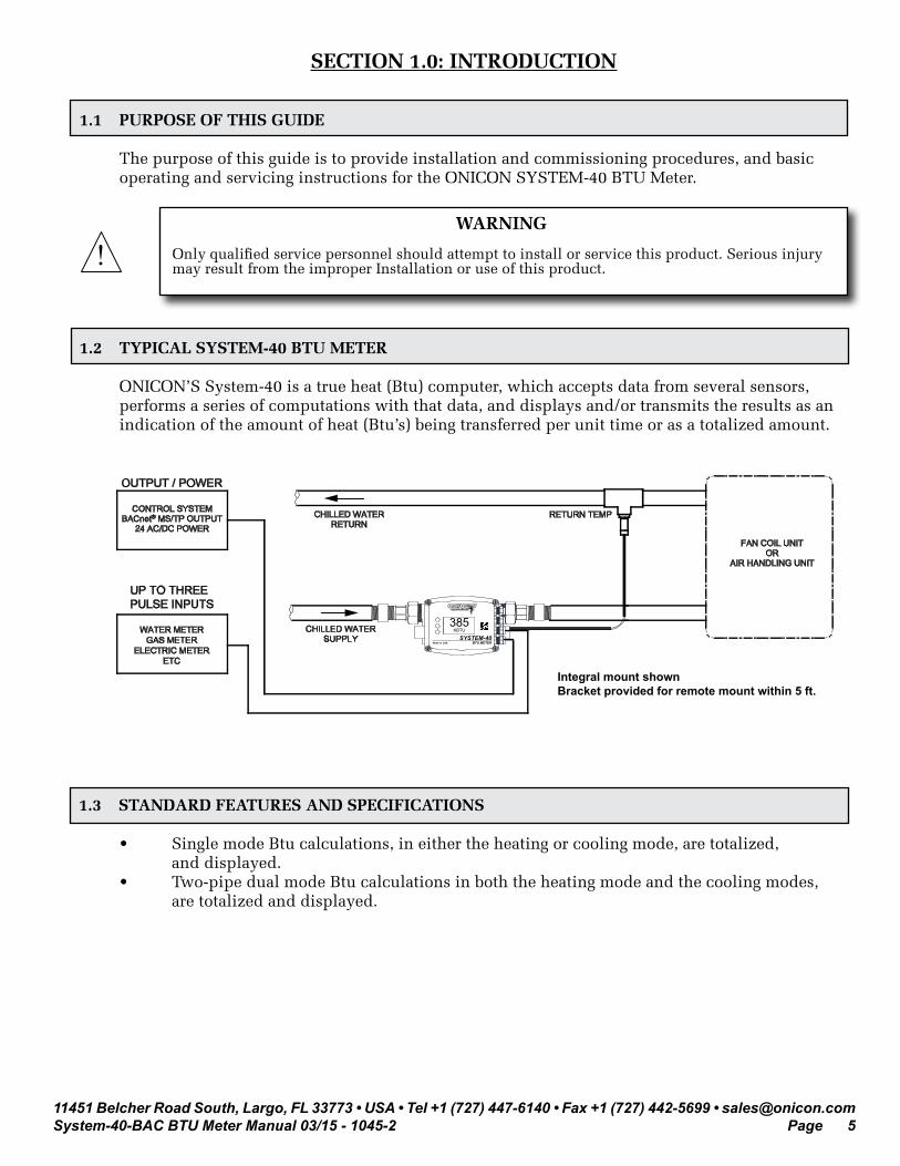
1.2 TYPICAL SYSTEM-40 BTU METER
ONICON’S System-40 is a true heat (Btu) computer, which accepts data from several sensors, performs a series of computations with that data, and displays and/or transmits the results as an indication of the amount of heat (Btu’s) being transferred per unit time or as a totalized amount.
CONTROL SYSTEMBACnet® MS/TP OUTPUT
24 AC/DC POWER
FAN COIL UNITOR
AIR HANDLING UNIT
CHILLED WATERRETURN
CHILLED WATERSUPPLY
RETURN TEMP
WATER METERGAS METER
ELECTRIC METERETC
UP TO THREEPULSE INPUTS
OUTPUT / POWER
SYSTEM-40BTU METERMade in USA
KBTU/HR385
KBTU
Integral mount shownBracket provided for remote mount within 5 ft.

11451 Belcher Road South, Largo, FL 33773 • USA • Tel +1 (727) 447-6140 • Fax +1 (727) 442-5699 • [email protected] BTU Meter Manual 03/15 - 1045-2 Page 6
GENERAL SPECIFICATIONS*
CALIBRATIONFlow meter and temperature sensors are individually calibrated to N.I.S.T and or international metrological standards, followed by a complete system calibration. Field commissioning is also available.
ACCURACYFLOWMeets EN1434 Class 1 accuracy requirements ± 1% of reading over 25:1 turndown ± 2% of reading over 100:1 turndownOverall turndown exceeds 500:1 Repeatability: ≤ ± 0.2%
TEMPERATURE Field serviceable MID certified matched pair of 2-wire 1000Ω platinum RTDs Calibrated to a differential measurement uncertainty of ± 0.18° F Meets EN1434/C900.1 accuracy requirements for 3K sensors
CALCULATORComputation error: ≤ 0.09% @ 30° F ∆t Meets EN1434 Class 1 requirements with 3K minimum ∆t
ELECTRICALPOWER SUPPLY REQUIREMENTS 12-36 VAC, 50/60 Hz, 15 VA maximum 12-42 VDC, 15 W maximum
CLOCK /CALENDARReal-time clock / calendar with lithium battery back-up. Estimated battery life ≥ 10 years
PROGRAMMINGFactory programmed for specific application. Field programming available through the user interface or via serial interface using a PC.
MEMORYNonvolatile FLASH memory retains all program parameters and totalized values in the event of power loss.
AUXILIARY PULSE INPUTS Three totalizing pulse inputs for use with sinking open collector or dry contact outputs Pulse duration: 50 ms minimumSinking current: 1 mA maximum
NETWORK CONNECTION Isolated RS485 serial interfaceUnit load = ¼Recommended devices per segment = 32
MECHANICALFLOW SENSORIndividually wet calibrated inline flow sensor with direct path wetted ultrasonic flow transducers. IP65 inline flow body with male BSPP (straight) threads. Wetted components: Brass (Lead free) PEEK EPDM (FKM optional)
METER COUPLINGSBrass couplings with BSPP nut and male NPT threadsWetted components: Brass (Lead free) EPDM (FKM optional)
TEMPERATURE SENSOR PAIR2-wire platinum RTDs with 1.5m (4.9ft) cablesScrew in direct insertion RTDs with M10 (straight) threadsWetted components: Stainless steel
CALCULATORDetachable enclosure with user interface and backlit display includes a 5ft extension cable and remote mounting bracket IP65 polycarbonate plastic enclosure Wetted components: None
*Specifications subject to change without notice

11451 Belcher Road South, Largo, FL 33773 • USA • Tel +1 (727) 447-6140 • Fax +1 (727) 442-5699 • [email protected] BTU Meter Manual 03/15 - 1045-2 Page 7
1.4 ADDITIONAL REQUIRED HARDWARE
Customer supplied line size threaded tee.The standard System-40 BTU meter is provided with a single NPT bushing for use with a line size tee when installing the remote temperature sensor in the pipe opposite the flow sensor pipe.
1.5 WORKING ENVIRONMENT
The SYSTEM-40 was designed for installation and use indoors in residential, commercial and light industrial environments that are free of corrosive liquids and fumes, temperature extremes and excess vibration.
The operating ambient air temperature range is -13° F to 131° F. The electrical power should be relatively clean, free of excess high frequency noise and large voltage transients.
1.6 WARRANTY & SERIAL NUMBER
Warranty ONICON’s 2-year “No-fault” warranty reduces start-up costs by extending coverage for incidental damage during installation. Certain exclusions apply. Please refer to ONICON’s Conditions of Sale for details.
Serial NumberThe serial number of your SYSTEM-40 is located on the top of the calculator enclosure. The serial number is a unique identifier for the product. Please have this number available when contacting ONICON for assistance.
SECTION 2.0: UNPACKING
The SYSTEM-40 is generally shipped in one package unless optional hardware or equipment is ordered. Notify the freight carrier and ONICON if any items are damaged in transit.
2.1 CHECKING THAT YOU HAVE RECEIVED EVERYTHING
• The following items have been provided with your SYSTEM-40 BTU Meter:
(2) Line size process connection meter couplings with male NPT threads and sealing gaskets (shipped attached to meter)(1) Line size NPT x M10 bushing for remote temperature sensor * (1) SYSTEM-40 BTU Meter Installation and Operation Guide(1) SYSTEM-40 BTU Meter Certificate of Calibration
*Optional installation hardware may be provided in place of this fitting
Please notify ONICON if any of these items are missing.

11451 Belcher Road South, Largo, FL 33773 • USA • Tel +1 (727) 447-6140 • Fax +1 (727) 442-5699 • [email protected] BTU Meter Manual 03/15 - 1045-2 Page 8
SECTION 3.0: INSTALLATION
The SYSTEM-40 BTU Meter should be installed by experienced plumbers, electricians, and others with related knowledge and experience in the heating, cooling, and fluid metering fields. ONICON technical support personnel are available via telephone or email to provide technical assistance before, during and after installation. On-site field engineering, installation, and service are also available at an additional cost. The installer should use good trade practices and must adhere to all state and local building, or other, applicable codes.
Before you begin, clean the external surfaces of all pipes at the installation sites so that they are free of debris, foreign matter, solids, leak inhibitors, and chemically aggressive substances. Flush the entire system so that it is free of flux, solder, pipe and tube cuttings and any other free moving debris.
3.1 SITE SELECTION
Careful attention to the site selection for the system components will help the installers with the initial installation, reduce start-up problems, and make future maintenance easier. For example, do not install the flow sensor where it will be difficult for personnel to perform periodic maintenance. When selecting a site for mounting the system components, consider the criteria under Section 1.5: WORKING ENVIRONMENT, as well as the following.
The following limitations apply to the installation of the meter:
• The flow sensor body must be correctly oriented with respect to the direction of flow in the pipe. Meters installed with reversed flow will not function.
• The System-40 is provided with 4.9ft (1.5m) cable lengths for the flow sensor and temperature sensors. Do not alter the cable lengths. Doing so will void the calibration and may invalidate the warranty.
• The maximum operating pressure for the flow sensor body, the direct insertion temperature sensors and the temperature sensor adapter bushings is 400psi.
• Ball valves provided for use with direct insertion temperature sensors have a maximum pressure rating of 232psi.
• Thermowells provided with the System-40 have a maximum pressure rating of 400psi.• At fluid temperatures above 212°F the calculator enclosure should be remote mounted.• Do not install the meter in close proximity to strong sources of electromagnetic
interference (e.g. electric motors, VFD’s, etc.)
i IMPORTANT NOTE
Proper site selection is critical to the performance of this Btu meter. Both the flow sensor and the remote temperature sensor must be properly located within the piping system in order to ensure an accurate energy measurement.

11451 Belcher Road South, Largo, FL 33773 • USA • Tel +1 (727) 447-6140 • Fax +1 (727) 442-5699 • [email protected] BTU Meter Manual 03/15 - 1045-2 Page 9
3.2 INSTALLING THE FLOW SENSOR
When properly installed, the flow sensor will only measure flow associated with that portion of the piping system for which the energy measurement is being made. The flow sensor may be installed in either the supply or return pipe of the heat exchange circuit. Before you install the meter, the entire piping system should be flushed and free of debris. Please refer to the diagrams below when selecting the installation location. While many installation locations require little, if any, straight unobstructed pipe upstream or downstream of the sensor location, it is always recommended that the sensor be located with as much straight pipe upstream of the sensor as possible.
A. This is a recommended position for the flow sensor. B. This is a recommended position for the flow sensor. C. Avoid installation locations where air can become trapped in the piping system. D. This is an acceptable installation location for closed loop pressurized systems. E. Do not install the sensor downstream of modulating valves or partially open valves.
Fully open isolation valves (e.g. ball valves) are OK. F. Do not install the flow sensor at the inlet of a pump or anywhere else where the
operating pressure in the pipe may drop below ambient pressure levels. To prevent cavitation, the minimum recommended operating pressure at the installation location should be at least 5psig.
G. Avoid installing the meter downstream of multiple bends out of plane with each other where there are less than 10 diameters of straight unobstructed pipe between bends.
A
B
C
D
E & F
G
Flow Direction
Flow Direction

11451 Belcher Road South, Largo, FL 33773 • USA • Tel +1 (727) 447-6140 • Fax +1 (727) 442-5699 • [email protected] BTU Meter Manual 03/15 - 1045-2 Page 10
IMPORTANT NOTE
The flow sensor body must be correctly oriented with respect to the direction of flow in the pipe. Meters installed with flow in the reverse direction will not function.
i
The calculator enclosure may be rotated around the axis of the flow sensor into three different positions. To rotate, temporarily slide the enclosure off the flow sensor mounting brackets. Remove the two retaining screws and reposition the mounting brackets as required. Reinstall the enclosure with the display properly oriented for viewing. Mounting tracks on the back of the enclosure allow for mounting in any orientation.
Flow DirectionThe sensor port is always on the downstream end of meter.
Retaining Nut SealCoupling
Slide calculator enclosure to remove from sensor mounting brackets
Slide Enclosure
Mounting Tracks
Retaining Screw
Retaining Screw
IMPORTANT NOTE
When installing the meter in a vertical pipe with upward flow you must rotate the enclosure back plate 180° when rotating the display 90°. To accomplish this, temporarily remove the 4 cover screws and rotate the backing plate.
i
The flow sensor is installed with threaded meter couplings and flat sealing gaskets as shown below. Orient the sensor body by aligning the flow direction arrow with the direction of flow in the pipe.

11451 Belcher Road South, Largo, FL 33773 • USA • Tel +1 (727) 447-6140 • Fax +1 (727) 442-5699 • [email protected] BTU Meter Manual 03/15 - 1045-2 Page 11
Orient the meter as shown below. The meter may be installed with upward or downward flow in vertical pipes in closed loop pressurized systems. Avoid any installation locations where the pipe may not be completely full.
Back View Side View
Back View
Side View
Do not orient meter as shown above
Preferred Orientation for Horizontal Housing
11451 Belcher Road South, Largo, FL 33773 • USA • Tel +1 (727) 447-6140 • Fax +1 (727) 442-5699 • [email protected] BTU Meter Manual 03/15 - 1045-2 Page 12
3.3 INSTALLING THE TEMPERATURE SENSORS
When properly installed, the temperature sensors will only measure the inlet and outlet temperatures of the heat exchange circuit where the energy measurement is being made. Before you install the sensors, the entire piping system should be flushed and free of debris.
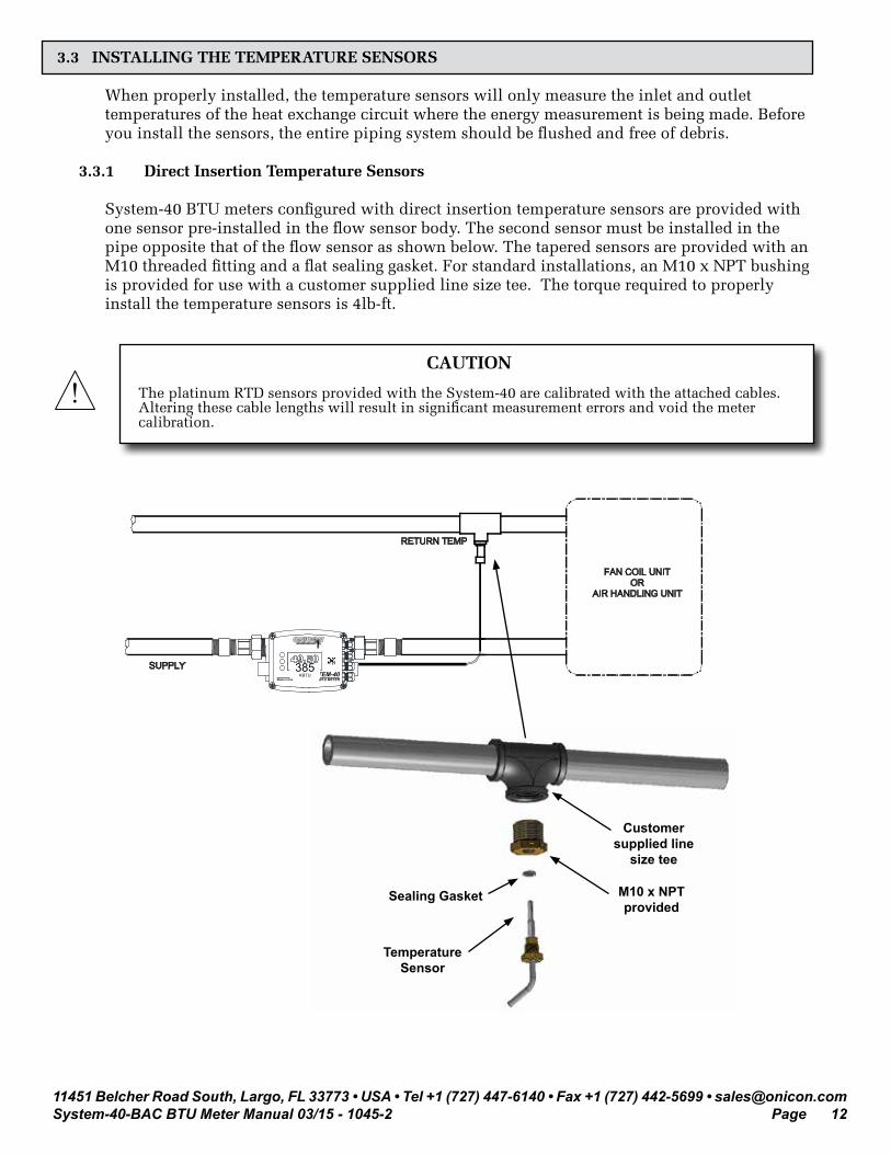
3.3.1 Direct Insertion Temperature Sensors
System-40 BTU meters configured with direct insertion temperature sensors are provided with one sensor pre-installed in the flow sensor body. The second sensor must be installed in the pipe opposite that of the flow sensor as shown below. The tapered sensors are provided with an M10 threaded fitting and a flat sealing gasket. For standard installations, an M10 x NPT bushing is provided for use with a customer supplied line size tee. The torque required to properly install the temperature sensors is 4lb-ft.
FAN COIL UNITOR
AIR HANDLING UNIT
SUPPLY
RETURN TEMP
SYSTEM-40BTU METERMade in USA
KBTU/HR385KBTU
Customer supplied line
size tee
M10 x NPT provided
Sealing Gasket
Temperature Sensor
! CAUTION
The platinum RTD sensors provided with the System-40 are calibrated with the attached cables. Altering these cable lengths will result in significant measurement errors and void the meter calibration.

11451 Belcher Road South, Largo, FL 33773 • USA • Tel +1 (727) 447-6140 • Fax +1 (727) 442-5699 • [email protected] BTU Meter Manual 03/15 - 1045-2 Page 13
3.4 REMOTE MOUNTING THE CALCULATOR ENCLOSURE
The System-40 is provided with a mounting bracket and the cables required for remote mounting the calculator. All 3 cables are 4.9ft (1.5m) in length. These cable lengths must not be altered. The remote mounting bracket is shown below. It has two 0.219” mounting holes designed to accommodate #10 screws. It also has parallel slots that allow for the use of pipe clamps when mounting the enclosure on a stanchion or pipe. The bracket may be used as a template for marking locations for holes.
Slot for Pipe Clamps
0.219”
Slide Tracks
Slide Tracks

11451 Belcher Road South, Largo, FL 33773 • USA • Tel +1 (727) 447-6140 • Fax +1 (727) 442-5699 • [email protected] BTU Meter Manual 03/15 - 1045-2 Page 14
3.5 POWER AND SIGNAL WIRING CONNECTIONS
The System-40 is provided with 4 glands on the right hand side of the enclosure for power and signal cables. Each includes a strain relief for securing the cabling and a sealing cap. The power cable should enter the enclosure through the bottom gland. Do not remove the sealing caps from unused cable glands. To access the wiring connections, remove the 4 cover screws shown below.
Cover ScrewsInstall power cable here
Cover Screws
1 2 3 4 5 6 7 8 1 2 3
109
H5 SERIAL
TB3
TB2
H3
43
21
43
21
1 2 1 2 1 2 1 2TB8 TB7 TB6 TB5 SW6 SW7 SW2 SW1C34
C33
R6
DS3R8 H2 SERIAL
21
GRD
DS2R60
3JM
P5
1
CAUT
ION
INST
ALL +
SID
E UP
CR20
32 B
ATTE
RYB
AT1
Internal RTD(Flow)
External RTD
24V
AC/D
C (+
)
24V
COMM
ON (-
)
AUX
1 (+)
AUX
1 (-)
AUX
2 (+)
AUX
2 (-)
AUX
3 (+)
AUX
3 (-)
RS48
5 (+)
RS48
5 (-)
RS48
5 COM
MON
TB1 TB4
COMMISSIONING MICROPROCESSORRESET
RS485 Termination1 - 2 = 120 Ω 2 - 3 = None
System-40-BAC Enclosure Label
1048 / 33354 02-1511451 Belcher Road South, Largo, FL 33773 • USA • Tel +1 (727) 447-6140 • Fax +1 (727) 442-5699
www.onicon.com • [email protected]
Actual Size - 4.125” x 2.875”
Cutline
Remote (external) Temperature Sensor
Name Terminal # Description
1000 ohm TB2-1 RTD signal wire
Not used TB2-2 No Connection
Not used TB2-3 No Connection
1000 ohm RTD TB2-4 RTD signal wire
Flow (internal) Temperature Sensor*
Name Terminal # Description
1000 ohm TB3-1 RTD signal wire
Not used TB3-2 No Connection
Not used TB3-3 No Connection
1000 ohm RTD TB3-4 RTD signal wire
Power and Signal Inputs (18 - 22 AWG wire)
Name Terminal # Description
24V ac/dc (+) TB1-1 12 - 36Vac, 50/60Hz, 15 VA max.12-42Vdc, 15W max.24V ac/dc Common (-) TB1-2
Aux Pulse Input # 1 (+) TB1-3For use with open collector sinking and dry contact ouputs
Pulse Duration: 50ms min.Sinking Current: 1mA max.
Aux Pulse Input # 1 (-) TB1-4
Aux Pulse Input # 2 (+) TB1-5
Aux Pulse Input # 2 (-) TB1-6
Aux Pulse Input # 3 (+) TB1-7
Aux Pulse Input # 3 (-) TB1-8
RS485 (20 - 24 AWG wire)
Name TB4 Description
RS485 B (+) TB4-1RS485 Unit Load = 1/4Recommended Devicesper Segment = 32
RS485 A (-) TB4-2
RS485 Common TB4-3
RS485 Termination Resistor
Name JMP5 Description
120 ohm Position 1 Jumper Position 1 & 2 = 120 ohms120 ohm Position 2
None Position 3 Jumper Position 2 & 3 = No Termination
* This sensor must be in the same pipe as the flow sensor.
i IMPORTANT NOTE
Open isolation valves, leak test and purge the piping system of air prior to wiring the meter.

11451 Belcher Road South, Largo, FL 33773 • USA • Tel +1 (727) 447-6140 • Fax +1 (727) 442-5699 • [email protected] BTU Meter Manual 03/15 - 1045-2 Page 15
SECTION 4.0: SYSTEM-40 START-UP AND COMMISSIONING
4.1 START-UP
When power is first applied to the meter the display will be illuminated and the following start screen will appear. Momentarily press SEL (select) to access the operating mode (User Screens) display pages.
Verify that the meter is functional by stepping through the display pages and confirming the flow rate and temperature data is within expected norms. Momentarily press NEXT or BACK to change the displayed page. A complete list of the display pages is provided on the following page.
Alarm Indication
Unit of Measure
When reviewing the displayed data, note the factory programmed engineering units on each display page (e.g. kBtu, gallons, kBtu/h, gpm, °F, etc.). Note any changes that may be necessary. These will need to be made during commissioning.
When reviewing the Supply and Return temperature display pages note which one has the word “FLOW” in the lower left corner of the page. This is an indication of the flow sensor location in the piping system. Verify the actual location of the flow sensor in the piping system. It is critical that the correct location (supply or return) be programmed into the meter.
! CAUTION
During start-up and commissioning, the FLOW location must be properly identified as being in the supply or return pipe of the heat exchange circuit. The sensor’s position must then be programmed into the meter. Failure to do so will result in significant errors in both the flow and energy measurements.
To return to the commissioning mode from the user screens, momentarily press MENU. The following page will appear. Momentarily press EXIT to return to the start screen.

11451 Belcher Road South, Largo, FL 33773 • USA • Tel +1 (727) 447-6140 • Fax +1 (727) 442-5699 • [email protected] BTU Meter Manual 03/15 - 1045-2 Page 16
4.1.1 Single and Dual Mode Display Pages

11451 Belcher Road South, Largo, FL 33773 • USA • Tel +1 (727) 447-6140 • Fax +1 (727) 442-5699 • [email protected] BTU Meter Manual 03/15 - 1045-2 Page 17
4.1.2 Additional Display Pages

11451 Belcher Road South, Largo, FL 33773 • USA • Tel +1 (727) 447-6140 • Fax +1 (727) 442-5699 • [email protected] BTU Meter Manual 03/15 - 1045-2 Page 18
4.2 COMMISSIONING
The last step in the installation process is commissioning the meter. Commissioning is a 2 step process. The first step is to review the mechanical installation to confirm that the flow sensor and temperature sensor(s) are properly located in the piping system. The second step is a review of the meter program settings. Both steps must be completed in order to finish the installation. A simple commissioning checklist is shown below. A copy of this may be found online at www.onicon.com/system-40/XXXX.
Commissioning Checklist
Part 1 Mechanical installation
Confirm that the flow sensor is properly located in the piping system (Sec. 3.1 & 3.2).
Confirm that the flow sensor is properly oriented with respect to flow direction (Sec. 3.2).
Confirm that the temperature sensor(s) is properly located in the piping system (Sec. 3.3).
Part 2 Programming
Confirm that the flow sensor location in the piping system (supply or return) is programmed into the meter (Sec. 4.1 & 4.2.1).
Verify that the Units of Measure Settings in the meter are correct (Sec. 4.1 & 4.2.1).
Confirm that there are no alarm indications and the meter is functional (Sec. X.X).
4.2.1 Commissioning following initial power-up
During initial power-up, the following display pages will appear the commissioning option is selected. The settings shown below allow the installer to set BACnet® parameters, the flow sensor location (supply or return pipe) and the date and time. If the factory pre-programmed engineering units for flow, energy and temperature are correct, press SAVE to exit commissioning once the correct date has been set. Momentarily press NEXT if you wish access the remaining commissioning mode display pages shown on the next page.

11451 Belcher Road South, Largo, FL 33773 • USA • Tel +1 (727) 447-6140 • Fax +1 (727) 442-5699 • [email protected] BTU Meter Manual 03/15 - 1045-2 Page 19
Commissioning
EXIT
NEXT
EDIT
BACnet Address
EXIT
NEXT
EDIT
Instance Number
EXIT
NEXT
EDIT
Baud Rate
10 - 255
570170 - 4194303
38400
Short Commissioning
EXIT
NEXT
EDIT
Meter Location
EXIT
NEXT
EDIT
Set Time
EXIT
NEXT
EDIT
Set Date
BACK
NEXT
SAVE
Set Meter
Supply
YYYY:MM:DD
HH:MM:SS
EXIT
NEXT
EDIT
Medium
EXIT
NEXT
EDIT
Flow
EXIT
NEXT
EDIT
Volume
Water
gpm
gallons
EXIT
NEXT
EDIT
Energy
EXIT
NEXT
EDIT
Energy Rate
EXIT
NEXT
EDIT
Temperature
kBtu
F
Btu/hr
Select Units
Select Units
Select Units
Select Units
Select Units
EXIT
NEXT
EDIT
Mode
SingleSingle or Dual
NEXT
EDIT
Aux Input 1
EXIT
NEXT
EDIT
Num Aux Inputs
00 - 3
Units of Measure Settings
NEXT
Set MeterNext to complete Installor adjust settings.
NEXT edits units ofmeasureSAVE completes installwith current settings
EXIT
Counts
EXIT
NEXT
EDIT
Target Date
EXIT
NEXT
EDIT
Aux Input 2
MM/DDReset Month/Day
EXIT
NEXT
SAVE
Set MeterNEXT repeats Meter SetSAVE completes installwith current settings
BACK
Counts
EXIT
NEXT
EDIT
Aux Input 3
Counts

11451 Belcher Road South, Largo, FL 33773 • USA • Tel +1 (727) 447-6140 • Fax +1 (727) 442-5699 • [email protected] BTU Meter Manual 03/15 - 1045-2 Page 20
4.3 SEALING THE METER
Once commissioning is complete install the two security seals provided with the meter as shown below.
5.0: DIAGNOSTIC FUNCTIONS
The ONICON System-40 has self diagnostic functions that continually monitor key operating parameters. A list of the alarm messages is shown below.
Displayed Message Description
System Fault System Fault is displayed with an error code. This message indicates a hardware malfunction. The meter will not calculate energy in this state.
Reverse Flow Flow is reversed through the meter. The meter will not calculate energy in this state.
Signal Fault This is a warning message that the flow signal is weak. It may indicate entrained air in the flow stream.
Dt< Minimum This is a warning message that the delta temperature is low. Empty Pipe The pipe is empty.Flow RTD Open The temperature sensor in the flow body is reading open.
The meter will not calculate energy in this state.Flow RTD Short The temperature sensor in the flow body is reading as a short
circuit. The meter will not calculate energy in this state.Remote RTD Open The remote temperature sensor is reading open. The meter
will not calculate energy in this state.Remote RTD Short The remote temperature sensor is reading as a short circuit.
The meter will not calculate energy in this state.Low Flow The flow reading is below the minimum flow threshold of
the meter (e.g. 0.03 gpm for ½” meter). The meter will not calculate energy in this state.
High Flow This is a warning message that the flow reading is above the maximum flow rate of the meter (e.g. 15 gpm for ½” meter).
Security Seals

11451 Belcher Road South, Largo, FL 33773 • USA • Tel +1 (727) 447-6140 • Fax +1 (727) 442-5699 • [email protected] BTU Meter Manual 03/15 - 1045-2 Page 21
SECTION 6.0: BACnet MS/TP
BACnet® MS/TP, serial interface connections are connected at terminal block TB4.
Transceiver: 2-wire, half-duplex (1/4 unit load)BACnet® address (MAC address) range: 1 - 255 (Default: 017)Device Instance: 0 - 4,194,303 (Default: 57017)Baud rate: 9600, 19200, 38400 or 76800 (Default: 38400)Termination: 120 ohms or none (Default: none)Biasing: NoneFlow control: None
6.1 BACnet® OBJECT TYPES
BACnet® Object Type# of Objects ImplementedDevice 1Analog Input 10Analog Value 22Binary Value 10Multistate Object 1Trend Log Multiple 1
6.2 PROTOCOL IMPLEMENTATION STATEMENT
BACnet® Protocol Revision: 10 Device Profile (Annex L): BACnet® Application Specific Controller (B-ASC)MS/TP master (Clause 9), baud rate(s): 9600, 19200, 38400 & 76800Device Address Binding: NoBBMD support registration by Foreign Devices: NoCharacter Set Supported: ANSI X3.4
BACnet® Interoperability Building Blocks Supported (Annex K):Data Sharing-ReadProperty-B (DS-RP-B)Data Sharing - ReadProperty Multiple - B (DS-RPM-B)Data Sharing-WriteProperty-B (DS-WP-B)Data Sharing - WriteProperty Multiple - B (DS-WPM-B)Device Management-Dynamic Device Binding-B (DM-DDB-B)Device Management-Dynamic Object Binding-B (DM-DOB-B)Device Management-DeviceCommunicationControl-B (DM-DCC-B)Device Management-Time Synchronization-B (DM-TS-B)Device Management - UTC Time Synchronization – B (DM-UTS-B)Trending - View and Modify Multiple Values - I – B (T-VMMV-I-B)
Standard Object Types Supported: Device Object Binary Value Object Analog Input Object Multi-State Value
Analog Value Object Trend Log Multiple

11451 Belcher Road South, Largo, FL 33773 • USA • Tel +1 (727) 447-6140 • Fax +1 (727) 442-5699 • [email protected] BTU Meter Manual 03/15 - 1045-2 Page 22
6.3 DEVICE OBJECT
Property Default Value Read-only or Writable
Comment
Object Identifier 57017 Writable 0-4,194,303Object Name System-40-XXXXXX Read-onlyObject Type Device Read-onlySystem Status Operational Read-onlyVendor Name ONICON Inc. Read-onlyModel Name System-40-BAC Read-onlyFirmware Rev. 000.000.000 Read-onlyLocation Customer Location Writable 32 char. MaxDescription Customer Description Writable 32 char. MaxProtocol Version 1 Read-onlyProtocol Revision 10 Read-onlyServices Supported Read property, Read property
multiple, Write property, Write property multiple, Read range, Who-has, I have, Who-is, I-am, Device communications control, Time synchronization, UTC time synchronization
Read-only
Object Types Supported Analog input, Analog value, Binary input, Device, Multi-state value, Trend log multiple
Read-only
Object List (Device, 57017), (analog input, 1 – 10), (analog value, 1 – 22), (binary value, 1 – 10), (trend log multiple, 1), (multi state value, 1)
Read-only
Max ADPU Length 480 Read-onlyLocal Time Device current time Read-onlyLocal Date Device current date Read-onlyUTC Offset -300 WritableDaylight Savings Status False WritableAPDU Timeout 6000 Read-only# of APDU Retries 3 WritableMax Master 127 Read-onlyDevice Address Binding Read-only ActiveDatabase Revision 1 Read-only

11451 Belcher Road South, Largo, FL 33773 • USA • Tel +1 (727) 447-6140 • Fax +1 (727) 442-5699 • [email protected] BTU Meter Manual 03/15 - 1045-2 Page 23
6.4 ANALOG INPUT(S)
Property Default Value Read-only or Writable
Comment
Object Identifier Analog-input,1 to analog-input,10 Read-onlyObject Name Various Read-onlyObject Type Analog-input Read-onlyPresent Value REAL WritableDescription Analog-input,# Name Read-onlyStatus Flags (F,F,F,F) Read-onlyEvent State normal Read-onlyReliability No-fault-detected Read-onlyOut-of-Service FALSE WritableUpdate interval 100 Read-onlyUnits Various Read-onlyMin-Present-Value -1000000000 Read-onlyMax-Present-Value 1000000000 Read-onlyResolution 0.000001 Read-only
6.5 ANALOG VALUE(S)
Property Default Value Read-only or Writable
Comment
Object Identifier Analog-value,1 to analog-value,22 Read-onlyObject Name Various Read-onlyObject Type Analog-value Read-onlyPresent Value REAL WritableDescription Analog-value,# Name Read-onlyStatus Flags (F,F,F,F) Read-onlyEvent State normal Read-onlyReliability No-fault-detected Read-onlyOut-of-Service FALSE WritableUnits Various Read-onlyPriority Array NULL, NULL, NULL, NULL,
NULL, NULL, NULL, NULL, NULL, NULL, NULL, NULL, NULL, NULL, NULL, NULL
Read-only
Relinquish Default 0 Read-only

11451 Belcher Road South, Largo, FL 33773 • USA • Tel +1 (727) 447-6140 • Fax +1 (727) 442-5699 • [email protected] BTU Meter Manual 03/15 - 1045-2 Page 24
6.6 BINARY VALUE(S)
Property Default Value Read-only or Writable
Comment
Object Identifier Binary-value,1 to binary-value,10 Read-onlyObject Name Various Read-onlyObject Type Binary-value Read-onlyPresent Value 0 WritableDescription Binary-value,# Name Read-onlyStatus Flags (F,F,F,F) Read-onlyEvent State normal Read-onlyReliability No-fault-detected Read-onlyOut-of-Service FALSE WritableElapsed Active Time Various Read-onlyPriority Array (NULL, NULL, NULL, NULL,
NULL, NULL, NULL, NULL, NULL, NULL, NULL, NULL, NULL, NULL, NULL, NULL)
Read-only
Relinquish Default 0 Read-only
6.7 MULTI STATE VALUE Property Default Value Read-only or
Writable Comment
Object Identifier Multi-state-value,1 Read-onlyObject Name Meter Status Read-onlyObject Type multi-state-value Read-onlyPresent Value 1 WritableDescription Multi-state-value,# Name Read-onlyStatus Flags (F,F,F,F) Read-onlyEvent State normal Read-onlyReliability No-fault-detected Read-onlyOut-of-Service FALSE WritableNumber of States 11 Read-onlyState Text Normal, Low Supply Temperature,
High Supply Temperature, Low Return Temperature, Delta T< Minimum, High Energy Rate, Low Signal Quality, Comm Error, Low Supply Voltage, System Fault
Read-only
Relinquish Default 0 Read-only

11451 Belcher Road South, Largo, FL 33773 • USA • Tel +1 (727) 447-6140 • Fax +1 (727) 442-5699 • [email protected] BTU Meter Manual 03/15 - 1045-2 Page 25
6.8 TREND LOG MULTIPLE
Property Default Value Read-only or Writable
Comment
Object Identifier Trend-log-multiple,1 Read-onlyObject Name Log Data Read-onlyObject Type Trend-log-multiple Read-onlyDescription Trend-log-multiple,# Name Read-onlyStatus Flags (F,F,F,F) Read-onlyEvent State normal Read-onlyReliability No-fault-detected Read-onlyEnable TRUE WritableLog Device Property Read-only See Note BelowLogging Type POLLED Read-onlyLog Interval 9000 WritableStop When Full FALSE Read-onlyBuffer Size 480 Read-onlyLog Buffer Read-onlyRecord Count 0 WritableTotal Record Count 0 Read-only
Note: Log Device Property – Log intervals can be set over a range of 30 seconds to 60 minutes. The following objects can be logged:
Analog-input, 1 Energy Rate Analog-input, 2 Volume RateAnalog-input, 3 Supply Temperature Analog-input, 4 Return TemperatureAnalog-input, 5 Delta TemperatureAnalog-value, 1 Volume Total Mode 1 Analog-input, 2 Volume Total Mode 2Analog-value, 9 Volume Total Mode 1 Analog-input, 10 Volume Total Mode 2Multi-state-value, 1 Meter Status
11451 Belcher Road South, Largo, FL 33773 • USA • Tel +1 (727) 447-6140 • Fax +1 (727) 442-5699 • [email protected] BTU Meter Manual 03/15 - 1045-2 Page 26
APPENDIX A
A-1 SYSTEM-40-BAC WIRING DIAGRAM
A-2 CHANGING BACNET SETTINGS OR METER PROGRAMMING AFTER COMMISSIONING
A-3 CONDITIONS OF SALE

11451 Belcher Road South, Largo, FL 33773 • USA • Tel +1 (727) 447-6140 • Fax +1 (727) 442-5699 • [email protected] BTU Meter Manual 03/15 - 1045-2 Page A-1
SYSTEM-40-BAC WIRING DIAGRAM
1 2 3 4 5 6 7 8 1 2 3
109
H5 SERIAL
TB3
TB2
H3
43
21
43
21
1 2 1 2 1 2 1 2TB8 TB7 TB6 TB5 SW6 SW7 SW2 SW1C34
C33
R6
DS3R8 H2 SERIAL
21
GRD
DS2R60
3JM
P5
1
CAUT
ION
INST
ALL +
SID
E UP
CR20
32 B
ATTE
RYB
AT1
Internal RTD(Flow)
External RTD
24V
AC/D
C (+
)
24V
COMM
ON (-
)
AUX
1 (+)
AUX
1 (-)
AUX
2 (+)
AUX
2 (-)
AUX
3 (+)
AUX
3 (-)
RS48
5 (+)
RS48
5 (-)
RS48
5 COM
MON
TB1 TB4
COMMISSIONING MICROPROCESSORRESET
RS485 Termination1 - 2 = 120 Ω 2 - 3 = None
System-40-BAC Enclosure Label
1048 / 33354 02-1511451 Belcher Road South, Largo, FL 33773 • USA • Tel +1 (727) 447-6140 • Fax +1 (727) 442-5699
www.onicon.com • [email protected]
Actual Size - 4.125” x 2.875”
Cutline
Flow (external) Temperature Sensor*Name Terminal # Description
1000 ohm TB2-1 RTD signal wire
Not used TB2-2 No Connection
Not used TB2-3 No Connection
1000 ohm RTD TB2-4 RTD signal wire
Remote (internal) Temperature SensorName Terminal # Description
1000 ohm TB3-1 RTD signal wire
Not used TB3-2 No Connection
Not used TB3-3 No Connection
1000 ohm RTD TB3-4 RTD signal wire
Power and Signal Inputs (18 - 22 AWG wire)Name Terminal # Description
24V ac/dc (+) TB1-1 12 - 36Vac, 50/60Hz, 15 VA max.12-42Vdc, 15W max.24V ac/dc Common (-) TB1-2
Aux Pulse Input # 1 (+) TB1-3For use with open collector sinking and dry contact ouputs
Pulse Duration: 50ms min.Sinking Current: 1mA max.
Aux Pulse Input # 1 (-) TB1-4
Aux Pulse Input # 2 (+) TB1-5
Aux Pulse Input # 2 (-) TB1-6
Aux Pulse Input # 3 (+) TB1-7
Aux Pulse Input # 3 (-) TB1-8
RS485 (20 - 24 AWG wire)Name TB4 Description
RS485 B (+) TB4-1RS485 Unit Load = 1/4Recommended Devicesper Segment = 32
RS485 A (-) TB4-2
RS485 Common TB4-3
RS485 Termination ResistorName JMP5 Description
120 ohm Position 1 Jumper Position 1 & 2 = 120 ohms120 ohm Position 2
None Position 3 Jumper Position 2 & 3 = No Termination
* This sensor must be in the same pipe as the flow sensor.

11451 Belcher Road South, Largo, FL 33773 • USA • Tel +1 (727) 447-6140 • Fax +1 (727) 442-5699 • [email protected] BTU Meter Manual 03/15 - 1045-2 Page A-2
Changing BACnet Settings or Meter Programming After Commissioning BACnet settings and meter programming can be changed after commissioning is complete. In order to accomplish this it will be necessary to re-open the enclosure (Refer to section 3.5). Once the cover is open locate the commissioning button.
DONE
NEXT
EDIT
BACnet Address
DONE
NEXT
EDIT
Instance Number
DONE
NEXT
EDIT
Baud Rate
10 - 255
570170 - 4194303
38400
DONE
NEXT
EDIT
Set Time
DONE
NEXT
EDIT
Set Date
YYYY:MM:DD
HH:MM:SS
Briefly press commissioning once to re-enter the BACnet and date/time settings menu shown below. Press the DONE button at any time to save changes and exit.
To re-enter the Units of measure setting menu pages shown below, press and hold the commissioning button for 5 seconds. Press DONE button at any time to save the changes and exit.
DONE
NEXT
EDIT
Medium
DONE
NEXT
EDIT
Flow
DONE
NEXT
EDIT
Volume
Water
gpm
gallons
DONE
NEXT
EDIT
Energy
DONE
NEXT
EDIT
Energy Rate
DONE
NEXT
EDIT
Temperature
kBtu
F
Btu/hr
Select Units
Select Units
Select Units
Select Units
Select Units
DONE
NEXT
EDIT
Mode
SingleSingle or Dual
NEXT
EDIT
Aux Input 1
DONE
NEXT
EDIT
Num Aux Inputs
00 - 3
Units of Measure Settings
Counts
DONE
NEXT
EDIT
Target Date
DONE
NEXT
EDIT
Aux Input 2
MM/DDReset Month/Day
DONE
DONE
NEXT
EDIT
Aux Input 3
DONE
NEXT
EDIT
Meter Location
Supply
Counts
Counts
11451 Belcher Road South, Largo, FL 33773 • USA • Tel +1 (727) 447-6140 • Fax +1 (727) 442-5699 • [email protected] BTU Meter Manual 03/15 - 1045-2 Page A-3
CONDITIONS OF SALE1. ACCEPTANCE: The following Conditions of Sale apply to all sales of ONICON’s products. These provisions shall apply even if ONICON fails to object to provisions appearing on, incorporated by, referenced in, or attached to Buyer’s purchase order form. Buyer’s acceptance of delivery of ONICON’s products constitutes its acceptance of these Conditions of Sale. 2. DELIVERY AND TITLE: All product shipments are Ex Works shipping point and title passes to the Buyer at the time ONICON delivers the merchandise to the carrier. Risk of loss or damage to the product passes to the Buyer at the time ONICON delivers the product to the carrier. The Buyer immediately upon receipt should inspect all shipments, and should there be any evidence of damageorlossintransit,Buyermustfileclaimsortracersuponcarrier.ONICONwillassistintracingshipmentsuponrequest.
3. LIMITED WARRANTY: ONICON warrants that for a period of two (2) years following the date of original shipment of an ONICONproduct:(i)theproductwillconformtoONICON’sstandardwrittenspecificationsapplicabletosuchproductineffect onthedateofBuyer’sorder,orasmodifiedbyONICON’squotationorBuyer’spurchaseorderacceptedbyONICON,(ii)the product will be free from defects in workmanship, and (iii) that ONICON has title to the product prior to shipment to the Buyer; provided, however, that the warranties provided herein shall be void and may not apply in the event Buyer misuses or damages a product, including, but not limited to, any use by the Buyer of a product for an application other than one of a type approved by ONICON. ONICON’s sole liability and Buyer’s sole remedy for any breach of the foregoing warranty is for ONICON to repair or replace, at ONICON’s option, any defective product that is returned to ONICON during the warranty period. EXCEPT AS MAY BE SPECIFICALLY AGREED BY ONICON IN WRITING IN RELATION TO EACH SALE, NO OTHER WARRANTIES SHALL APPLY, WHETHER EXPRESSED, IMPLIED OR STATUTORY, AND THERE SHALL BE NO IMPLIED WARRANTIES OF MERCHANTABILITY AND FITNESS FOR A PARTICULAR PURPOSE.
4. REMEDIES: ONICON’s OBLIGATION UNDER THE FOREGOING WARRANTIES IS LIMITED SOLELY TO REPAIR OR REPLACEMENT, AT ONICON’s OPTION, OF DEFECTIVE OR NONCONFORMING PRODUCTS. ONICON SHALL NOT BE LIABLE FOR CONSEQUENTIAL, INDIRECT, PUNITIVE, INCIDENTAL, OR SPECIAL DAMAGES WHETHER FOUND ON CONTRACT, TORT OR ANY OTHER THEORY OF LAW. No products shall be returned to ONICON without its prior consent and transportation and insurance costs shall be prepaid. Any repair or replacement of ONICON’s products under the foregoing warranty will be at no charge to the Buyer provided such repair is done at the ONICON factory or authorized service center. ONICON products that are repaired or replaced under this warranty will be returned to Buyer via the same method of shipment use to return the product to ONICON. Repair or replacement of ONICON products is conditioned upon ONICON’s acknowledgement of any alleged defect or nonconformance during the warranty period and issuance of a Return Authorization number. All product returns must reference the Return Authorization number on the outside of the shipping carton and on any paperwork referencing the return.
5. PRICESANDPAYMENTTERMS:Thepricessetforthinthemostrecentquoteoracknowledgementasapplicable,supersede allpreviouspricesorquotations.Allquotationsaresubjecttochangeorwithdrawalwithoutnoticeexceptasmaybespecifically notedonthefaceofthequotation.Thepricesshowndonotincludesales,exciseorgovernmentchargespayablebyONICONto Federal, State, or local authority. Any such tax or charge now or hereafter imposed upon the sale or shipment of the products under this contract will be added to the purchase price. Buyer agrees to reimburse ONICON for such tax or charge or provide ONICONwithanacceptableexemptioncertificate.Paymentofinvoiceswillbedue30daysfromthedateofshipmentofthe products contained therein. In the event that payment of an invoice is not received by the invoice due date, ONICON will assess a late fee not to exceed 1.5% per month or 18% per year, or the maximum allowable by law whichever is lower.
6. CANCELLATION: Buyer may cancel its order, or any part of it, by sending written notice of cancellation to ONICON and payingareasonablecancellationfeeasdeterminedbyONICON.Thereasonablecancellationfeewillreflect,amongother factors,theexpensesalreadyincurredandcommitmentsmadebyONICON,salesandadministrativecostsandprofitas determinedbyONICON.IfBuyerreceivedareducedpricebasedonthequantityofproductsordered,buthasnotpurchased theapplicablequantityatthetimeofcancellation,BuyerwillpaythepriceitwouldhavepaidhadONICON’ssalepricebeen basedonthequantityactuallypurchased.
7.CHANGES:IfBuyermakesanychangesinitsdrawings,designs,orspecificationsapplicableinanycontractwithONICON that cause an increase or decrease in the cost of performance of the contract, or if such changes result in rework or obsolescence, an equitableadjustmentshallbemadetothecontract.SuchchangesaresubjecttoONICON’spriorwrittenconsent.
8.EXCUSABLEDELAY:ONICONshallundernocircumstanceberesponsibleforfailuretofillanyorderororderswhendueto:fires, floods,riots,strikes,freightembargoesortransportationdelays,shortageoflabor,inabilitytosecurefuel,materialsupplies,orpower at current price or on account of shortages thereof, acts of God or of the public enemy, any existing or future laws or acts of the FederalorStateGovernment(includingspecifically,butnotexclusively,andorders,rulesorregulationsissuedbyanyofficialor agency of any such government) affecting the conduct of ONICON’s business with which ONICON in its judgment and discretion deems it advisable to comply as a legal or patriotic duty, or due to any cause beyond ONICON’s reasonable control.
9. PATENTS: ONICON shall defend all suits or proceedings brought against Buyer or its customers arising from claimed infringements of any patent, trademark, service mark or copyright for any product furnished by ONICON and shall indemnify it againstallcosts,fees,anddamagesontheconditionBuyerpromptlynotifiesONICONinwritingandprovidesinformationand assistance to enable ONICON to conduct the defense, provided that ONICON shall have no such obligation in case of infringementresultingfromONICON’sconformancetospecialrequirementsofBuyer.IfONICONisnotabletosettleanysuch suitorproceedingonacceptableterms,ONICONmay,atitsoption,requirereturnoftheinfringingproductandrefundthe purchase price to Buyer less a reasonable allowance for depreciation or use. 10. FAIR LABOR STANDARDS ACT: ONICON represents that all products delivered under this contract are furnished in accordance with the applicable provisions of the Fair Labor Standards Act as amended.
11. APPLICABLE LAW: This document and any resulting contract shall be governed by and construed in accordance with the laws of the State of Florida. The courts of the State of Florida and the federal courts located in Florida shall have jurisdiction and venue with respect to litigation to this contract. In the event of litigation, the prevailing party shall be entitled to recover attorney’s fees and costs from the non-prevailing party, including appellate attorney’s fees.
12.MODIFICATIONS:TheseConditionsofSalealongwiththeprices,quantities,deliveryschedulesandotherprovisionsand instructionsinapplicablequotationsbyONICONorBuyer’spurchaseordersacceptedbyONICONshallconstitutetheentire agreementbetweenONICONandBuyerpertainingtoanyresultingcontract.Theycanbemodifiedonlyinwriting.