sysmac cpm2c - farnell element14 · v notice: omron products are manufactured for use according to...
TRANSCRIPT
Cat.No. W356–E1–2
Programmable Controller
SYSMACCPM2C
OPERATION MANUAL

CPM2C Programmable ControllerOperation ManualRevised January 2000
!
!
!
v
Notice:OMRON products are manufactured for use according to proper procedures by a qualified operatorand only for the purposes described in this manual.
The following conventions are used to indicate and classify precautions in this manual. Always heedthe information provided with them. Failure to heed precautions can result in injury to people or dam-age to property.
DANGER Indicates an imminently hazardous situation which, if not avoided, will result in death orserious injury.
WARNING Indicates a potentially hazardous situation which, if not avoided, could result in death orserious injury.
Caution Indicates a potentially hazardous situation which, if not avoided, may result in minor ormoderate injury, or property damage.
OMRON Product ReferencesAll OMRON products are capitalized in this manual. The word “Unit” is also capitalized when it refersto an OMRON product, regardless of whether or not it appears in the proper name of the product.
The abbreviation “Ch,” which appears in some displays and on some OMRON products, often means“word” and is abbreviated “Wd” in documentation in this sense.
The abbreviation “PC” means Programmable Controller and is not used as an abbreviation for any-thing else.
Visual AidsThe following headings appear in the left column of the manual to help you locate different types ofinformation.
Note Indicates information of particular interest for efficient and convenient operationof the product.
1, 2, 3... 1. Indicates lists of one sort or another, such as procedures, checklists, etc.
OMRON, 1999All rights reserved. No part of this publication may be reproduced, stored in a retrieval system, or transmitted, in anyform, or by any means, mechanical, electronic, photocopying, recording, or otherwise, without the prior written permis-sion of OMRON.
No patent liability is assumed with respect to the use of the information contained herein. Moreover, because OMRON isconstantly striving to improve its high-quality products, the information contained in this manual is subject to changewithout notice. Every precaution has been taken in the preparation of this manual. Nevertheless, OMRON assumes noresponsibility for errors or omissions. Neither is any liability assumed for damages resulting from the use of the informa-tion contained in this publication.

TABLE OF CONTENTS
vii
PRECAUTIONS xi. . . . . . . . . . . . . . . . . . . . . . . . . . . . . . . . . 1 Intended Audience xii. . . . . . . . . . . . . . . . . . . . . . . . . . . . . . . . . . . . . . . . . . . . . . . . . . . . . . . . . . . 2 General Precautions xii. . . . . . . . . . . . . . . . . . . . . . . . . . . . . . . . . . . . . . . . . . . . . . . . . . . . . . . . . . 3 Safety Precautions xii. . . . . . . . . . . . . . . . . . . . . . . . . . . . . . . . . . . . . . . . . . . . . . . . . . . . . . . . . . . 4 Operating Environment Precautions xiii. . . . . . . . . . . . . . . . . . . . . . . . . . . . . . . . . . . . . . . . . . . . . 5 Application Precautions xiv. . . . . . . . . . . . . . . . . . . . . . . . . . . . . . . . . . . . . . . . . . . . . . . . . . . . . . 6 EC Directives xvi. . . . . . . . . . . . . . . . . . . . . . . . . . . . . . . . . . . . . . . . . . . . . . . . . . . . . . . . . . . . . .
SECTION 1Introduction 1. . . . . . . . . . . . . . . . . . . . . . . . . . . . . . . . . . . .
1-1 CPM2C Features and Functions 2. . . . . . . . . . . . . . . . . . . . . . . . . . . . . . . . . . . . . . . . . . . . . 1-2 System Configurations 7. . . . . . . . . . . . . . . . . . . . . . . . . . . . . . . . . . . . . . . . . . . . . . . . . . . . 1-3 Structure and Operation 11. . . . . . . . . . . . . . . . . . . . . . . . . . . . . . . . . . . . . . . . . . . . . . . . . . . 1-4 Functions Listed by Usage 18. . . . . . . . . . . . . . . . . . . . . . . . . . . . . . . . . . . . . . . . . . . . . . . . . 1-5 Comparison with the CPM1A and CPM2A 20. . . . . . . . . . . . . . . . . . . . . . . . . . . . . . . . . . . . 1-6 Preparation for Operation 27. . . . . . . . . . . . . . . . . . . . . . . . . . . . . . . . . . . . . . . . . . . . . . . . . .
SECTION 2Unit Components and Specifications 29. . . . . . . . . . . . . . . .
2-1 Specifications 30. . . . . . . . . . . . . . . . . . . . . . . . . . . . . . . . . . . . . . . . . . . . . . . . . . . . . . . . . . . 2-2 Unit Components 40. . . . . . . . . . . . . . . . . . . . . . . . . . . . . . . . . . . . . . . . . . . . . . . . . . . . . . . .
SECTION 3Installation and Wiring 59. . . . . . . . . . . . . . . . . . . . . . . . . . .
3-1 Design Precautions 60. . . . . . . . . . . . . . . . . . . . . . . . . . . . . . . . . . . . . . . . . . . . . . . . . . . . . . . 3-2 Selecting an Installation Site 61. . . . . . . . . . . . . . . . . . . . . . . . . . . . . . . . . . . . . . . . . . . . . . . 3-3 Installing the CPM2C 62. . . . . . . . . . . . . . . . . . . . . . . . . . . . . . . . . . . . . . . . . . . . . . . . . . . . . 3-4 Wiring and Connections 65. . . . . . . . . . . . . . . . . . . . . . . . . . . . . . . . . . . . . . . . . . . . . . . . . . .
SECTION 4Using Programming Devices 103. . . . . . . . . . . . . . . . . . . . . . .
4-1 SYSMAC-CPT Support Software 104. . . . . . . . . . . . . . . . . . . . . . . . . . . . . . . . . . . . . . . . . . . 4-2 SYSMAC Support Software (SSS) 111. . . . . . . . . . . . . . . . . . . . . . . . . . . . . . . . . . . . . . . . . . 4-3 Using a Programming Console 114. . . . . . . . . . . . . . . . . . . . . . . . . . . . . . . . . . . . . . . . . . . . . 4-4 Programming Console Operations 122. . . . . . . . . . . . . . . . . . . . . . . . . . . . . . . . . . . . . . . . . . . 4-5 Programming Example 145. . . . . . . . . . . . . . . . . . . . . . . . . . . . . . . . . . . . . . . . . . . . . . . . . . . .
SECTION 5Test Runs and Error Processing 151. . . . . . . . . . . . . . . . . . . .
5-1 Initial System Checks and Test Run Procedure 152. . . . . . . . . . . . . . . . . . . . . . . . . . . . . . . . . 5-2 Self-diagnostic Functions 153. . . . . . . . . . . . . . . . . . . . . . . . . . . . . . . . . . . . . . . . . . . . . . . . . . 5-3 Programming Console Operation Errors 156. . . . . . . . . . . . . . . . . . . . . . . . . . . . . . . . . . . . . . 5-4 Programming Errors 156. . . . . . . . . . . . . . . . . . . . . . . . . . . . . . . . . . . . . . . . . . . . . . . . . . . . . . 5-5 Troubleshooting Flowcharts 158. . . . . . . . . . . . . . . . . . . . . . . . . . . . . . . . . . . . . . . . . . . . . . . . 5-6 Maintenance Inspections 166. . . . . . . . . . . . . . . . . . . . . . . . . . . . . . . . . . . . . . . . . . . . . . . . . . 5-7 Battery Replacement 167. . . . . . . . . . . . . . . . . . . . . . . . . . . . . . . . . . . . . . . . . . . . . . . . . . . . .
SECTION 6Expansion Memory Unit 169. . . . . . . . . . . . . . . . . . . . . . . . . .
6-1 Overview 170. . . . . . . . . . . . . . . . . . . . . . . . . . . . . . . . . . . . . . . . . . . . . . . . . . . . . . . . . . . . . . 6-2 Specifications and Nomenclature 171. . . . . . . . . . . . . . . . . . . . . . . . . . . . . . . . . . . . . . . . . . . 6-3 Handling 172. . . . . . . . . . . . . . . . . . . . . . . . . . . . . . . . . . . . . . . . . . . . . . . . . . . . . . . . . . . . . . .

TABLE OF CONTENTS
viii
AppendicesA Standard Models 179. . . . . . . . . . . . . . . . . . . . . . . . . . . . . . . . . . . . . . . . . . . . . . . . . . . . . . . . . . . B Dimensions 185. . . . . . . . . . . . . . . . . . . . . . . . . . . . . . . . . . . . . . . . . . . . . . . . . . . . . . . . . . . . . . . .
Index 191. . . . . . . . . . . . . . . . . . . . . . . . . . . . . . . . . . . . . . . . . . Revision History 197. . . . . . . . . . . . . . . . . . . . . . . . . . . . . . . . .

ix
About this Manual:
The CPM2C is a compact, high-speed Programmable Controller (PC) designed for control operations insystems requiring from 10 to 120 I/O points per PC. There are two manuals describing the setup andoperation of the CPM2C: The CPM2C Operation Manual (this manual) and the CPM1/CPM1A/CPM2A/CPM2C/SRM1(-V2) Programming Manual (W353). (The CPM1/CPM1A/CPM2A/CPM2C/SRM1(-V2)Programming Manual is referred to as simply the Programming Manual in this manual.)
This manual describes the system configuration and installation of the CPM2C and provides a basicexplanation of operating procedures for the Programming Consoles. It also introduces the capabilities ofthe SYSMAC Support Software (SSS) and SYSMAC-CPT Support Software. Read this manual first toacquaint yourself with the CPM2C.
The Programming Manual (W353) provides detailed descriptions of the CPM2C’s programming func-tions. The SYSMAC Support Software Operation Manuals: Basics and C-series PCs (W247 and W248)provide descriptions of SSS operations for the CPM2C and other SYSMAC C-series PCs. The SYSMAC-CPT Support Software Quick Start Guide (W332) and User Manual (W333) provide descriptions of ladderdiagram operations in the Windows environment. The CX-Programmer User Manual (W361) and the CX-Server User Manual (W362) provide details of operations for the WS02-CXPC1-E CX-Programmer.
Please read this manual carefully and be sure you understand the information provided before attemptingto install and operate the CPM2C.
Section 1 gives a brief overview of the steps involved in developing of a CPM2C System, describes thepossible system configurations, and describes the CPM2C’s special features and functions.
Section 2 provides the technical specifications of the Units that go together to create a CPM2C PC anddescribes the main components of the Units.
Section 3 describes how to install and wire a CPM2C PC.
Section 4 describes SYSMAC and SYSMAC-CPT Support Software capabilities, how to connect the Pro-gramming Console, and how to perform the various programming operations.
Section 5 describes how to perform a test run and how to diagnose and correct the hardware and soft-ware errors that can occur during PC operation.
Section 6 describes how to use the CPM1-EMU01-V1 Expansion Memory Unit.
Appendix A provides tables of CPM2C Units and related products.
Appendix B provides the dimensions of CPM2C Units.
WARNING Failure to read and understand the information provided in this manual may result inpersonal injury or death, damage to the product, or product failure. Please read eachsection in its entirety and be sure you understand the information provided in the sectionand related sections before attempting any of the procedures or operations given.
!

xi
PRECAUTIONS
This section provides general precautions for using the Programmable Controller (PC) and related devices.
The information contained in this section is important for the safe and reliable application of the Programmable Con-troller. You must read this section and understand the information contained before attempting to set up or operate aPC system.
1 Intended Audience xii. . . . . . . . . . . . . . . . . . . . . . . . . . . . . . . . . . . . . . . . . . . . . . . . . . . . . . . . . . . . 2 General Precautions xii. . . . . . . . . . . . . . . . . . . . . . . . . . . . . . . . . . . . . . . . . . . . . . . . . . . . . . . . . . . 3 Safety Precautions xii. . . . . . . . . . . . . . . . . . . . . . . . . . . . . . . . . . . . . . . . . . . . . . . . . . . . . . . . . . . . 4 Operating Environment Precautions xiii. . . . . . . . . . . . . . . . . . . . . . . . . . . . . . . . . . . . . . . . . . . . . . 5 Application Precautions xiv. . . . . . . . . . . . . . . . . . . . . . . . . . . . . . . . . . . . . . . . . . . . . . . . . . . . . . . . 6 EC Directives xvi. . . . . . . . . . . . . . . . . . . . . . . . . . . . . . . . . . . . . . . . . . . . . . . . . . . . . . . . . . . . . . . .

!
!
!
!
!
!
3Safety Precautions
xii
1 Intended AudienceThis manual is intended for the following personnel, who must also have knowl-edge of electrical systems (an electrical engineer or the equivalent).
• Personnel in charge of installing FA systems.
• Personnel in charge of designing FA systems.
• Personnel in charge of managing FA systems and facilities.
2 General PrecautionsThe user must operate the product according to the performance specificationsdescribed in the operation manuals.
Before using the product under conditions which are not described in the manualor applying the product to nuclear control systems, railroad systems, aviationsystems, vehicles, combustion systems, medical equipment, amusement ma-chines, safety equipment, and other systems, machines, and equipment thatmay have a serious influence on lives and property if used improperly, consultyour OMRON representative.
Make sure that the ratings and performance characteristics of the product aresufficient for the systems, machines, and equipment, and be sure to provide thesystems, machines, and equipment with double safety mechanisms.
This manual provides information for programming and operating the Unit. Besure to read this manual before attempting to use the Unit and keep this manualclose at hand for reference during operation.
WARNING It is extremely important that a PC and all PC Units be used for the specifiedpurpose and under the specified conditions, especially in applications that candirectly or indirectly affect human life. You must consult with your OMRONrepresentative before applying a PC System to the above-mentionedapplications.
3 Safety Precautions
WARNING Connect the ground terminal of the Power Supply Unit (CPM2C-PA201) to aground or 100 Ω or less. Not doing so may result in electric shock.
WARNING Do not attempt to take any Unit apart while the power is being supplied. Doing somay result in electric shock.
WARNING Do not touch any of the terminals or terminal blocks while the power is beingsupplied. Doing so may result in electric shock.
WARNING Do not attempt to disassemble, repair, or modify any Units. Any attempt to do somay result in malfunction, fire, or electric shock.
WARNING Provide safety measures in external circuits (i.e., not in the ProgrammableController), including the following items, in order to ensure safety in the systemif an abnormality occurs due to malfunction of the PC or another external factoraffecting the PC operation. Not doing so may result in serious accidents.
• Emergency stop circuits, interlock circuits, limit circuits, and similar safetymeasures must be provided in external control circuits.
!
!
!
!
!
!
!
4Operating Environment Precautions
xiii
• The PC will turn OFF all outputs when its self-diagnosis function detects anyerror or when a severe failure alarm (FALS) instruction is executed. As a coun-termeasure for such errors, external safety measures must be provided to en-sure safety in the system.
• The PC outputs may remain ON or OFF due to deposition or burning of theoutput relays or destruction of the output transistors. As a countermeasure forsuch problems, external safety measures must be provided to ensure safety inthe system.
• If the 24-VDC output (service power supply) of the Power Supply Unit(CPM2C-PA201) is overloaded or shorted, the voltage may drop causing out-puts to turn OFF. External safety measures must be provided to ensure safetyin the system in such an event.
WARNING When handling the Memory Backup Battery, never drop, disassemble, distort,short-circuit, recharge, heat to a temperature exceeding 100°C, or throw intofire. Otherwise the Battery may explode, catch fire, or leak fluid.
WARNING When transferring programs to other nodes, or when making changes to I/Omemory, confirm the safety of the destination node before transfer. Not doing somay result in injury.
Caution Execute online edit only after confirming that no adverse effects will be causedby extending the cycle time. Otherwise, the input signals may not be readable.
Caution Tighten the screws on the terminal block of the Power Supply Unit(CPM2C-PA201) to a torque of 0.74 to 0.9 Nm. Loose screws may result inburning or malfunction.
Caution Do not connect the 24-VDC output (service power supply) or the Power SupplyUnit (CPM2C-PA201) to an AC power supply. Connecting it to an AC power sup-ply will damage the internal circuit.
4 Operating Environment Precautions
Caution Do not operate the control system in the following places:
• Locations subject to direct sunlight.
• Locations subject to temperatures or humidity outside the range specified inthe specifications.
• Locations subject to condensation as the result of severe changes in tempera-ture.
• Locations subject to corrosive or flammable gases.
• Locations subject to dust (especially iron dust) or salts.
• Locations subject to exposure to water, oil, or chemicals.
• Locations subject to shock or vibration.
Caution Take appropriate and sufficient countermeasures when installing systems in thefollowing locations:
• Locations subject to static electricity or other forms of noise.

!
!
!
5Application Precautions
xiv
• Locations subject to strong electromagnetic fields.
• Locations subject to possible exposure to radioactivity.
• Locations close to power supplies.
Caution The operating environment of the PC System can have a large effect on the lon-gevity and reliability of the system. Improper operating environments can lead tomalfunction, failure, and other unforeseeable problems with the PC System. Besure that the operating environment is within the specified conditions at installa-tion and remains within the specified conditions during the life of the system.
5 Application PrecautionsObserve the following precautions when using the PC System.
WARNING Always heed these precautions. Failure to abide by the following precautionscould lead to serious or possibly fatal injury.
• Always connect to a ground such that the grounding resistance does not ex-ceed 100 Ω when installing the Units. Not connecting to the correct groundmay result in electric shock.
• Always turn OFF the power supply to the PC before attempting any of the fol-lowing. Not turning OFF the power supply may result in malfunction or electricshock.
• Assembling the Units.
• Connecting or disconnecting the Expansion I/O Units or Expansion Units.
• Connecting or wiring the cables.
• Connecting or disconnecting the connectors.
• Setting DIP switches.
• Replacing the battery
Caution Failure to abide by the following precautions could lead to faulty operation of thePC or the system, or could damage the PC or PC Units. Always heed these pre-cautions.
• Fail-safe measures must be taken by the customer to ensure safety in theevent of incorrect, missing, or abnormal signals caused by broken signal lines,momentary power interruptions, or other causes.
• Emergency stop circuits, interlock circuits, limit circuits, and similar safetymeasures must be provided in external control circuits.
• Construct a control circuit so that power supply for the I/O circuits does notcome ON before power supply for the Unit. If power supply for the I/O circuitscomes ON before power supply for the Unit, normal operation may be tempo-rarily interrupted.
• If the operating mode is changed from RUN or MONITOR mode to PROGRAMmode, with the IOM Hold Bit ON, the output will hold the most recent status. Insuch a case, ensure that the external load does not exceed specifications. (Ifoperation is stopped because of an operation error (including FALS instruc-tions), the values in the internal memory of the CPU Unit will be saved, but theoutputs will all turn OFF.)
• For models with only the super-capacitor installed, the contents of the READ/WRITE enable area of the DM area, HR area, AR area, and CNT data areamay be damaged if the power is turned OFF for a long time. To prevent suchdamage, provide ladder program that will check AR 1314 in order to ensureproper operation of the system.
5Application Precautions
xv
• The life of relays largely varies depending on switching conditions. Be sure totest operating conditions using actual Units and use the product within the spe-cified number of switchings so as not to cause any performance problems. Us-ing the product with performance problems may result in defective insulationbetween circuits or burning of the relays.
• Install the Units properly so that they will not fall off.• Be sure that all the mounting screws, terminal screws, and cable connector
screws are tightened to the torque specified in the relevant manuals. Incorrecttightening torque may result in malfunction.
• Be sure that the terminal blocks and other items with locking devices are prop-erly locked into place. Improper locking may result in malfunction.
• Be sure that terminal blocks and connectors are connected in the specified di-rection with the correct polarity. Not doing so may result in malfunction.
• Use the Unit with the battery housing cover in place to prevent dust or foreignmatter from entering inside the Unit. Not doing so may result in malfunction.
• Install the expansion I/O connector cover to the last Unit (Expansion Unit orExpansion I/O Unit) to prevent dust or foreign matter from entering inside theUnit. Not doing so may result in malfunction.
• Be sure to attach the labels supplied with the CPM2C or provide other protec-tive covers when wiring in order to prevent dust or wiring cuttings from enteringthe Unit.
• Remove the label after the completion of wiring to ensure proper heat dissipa-tion. Leaving the label attached may result in malfunction.
• Use round crimp terminals for wiring the Power Supply Unit (CPM2C-PA201).Do not connect bare stranded wires directly to terminals. Connection of barestranded wires may result in burning.
• Be sure to perform wiring in accordance with the CPM2C Operation Manual.Incorrect wiring may result in burning.
• Use specified connectors and wiring materials (connector models:C500-CE241/C500-CE242/C500-CE243; terminal block models: AWG28-16with stripped length of 7 mm; Power Supply Unit terminal block: AWG22-14with stripped length of 7 mm).
• Do not apply voltages to the input terminals in excess of the rated input voltage.Excess voltages may result in burning.
• Do not apply voltages or connect loads to the output terminals in excess of themaximum switching capacity. Excess voltage or loads may result in burning.
• Install external breakers and take other safety measures against short-circuit-ing in external wiring. Insufficient safety measures against short-circuiting mayresult in burning.
• Always use the power supply voltage specified in the operation manuals. Anincorrect voltage may result in malfunction or burning.
• Check the user program for proper execution before actually running it on theUnit. Not checking the program may result in an unexpected operation.
• Double-check all wiring and switch settings before turning ON the power sup-ply. Incorrect wiring or switch settings may result in burning.
• Confirm that no adverse effect will occur in the system before attempting any ofthe following. Not doing so may result in an unexpected operation.
• Changing the operating mode of the PC.• Force-setting/force-resetting any bit in memory.• Changing the present value of any word or any set value in memory.
• Before touching the Unit, be sure to first touch a grounded metallic object inorder to discharge any static built-up. Not doing so may result in malfunction ordamage.

6EC Directives
xvi
• Do not pull on the cables or bend the cables beyond their natural limit. Doingeither of these may break the cables.
• Do not apply forces exceeding 50 N to connector sections.• Do not place objects on top of the cables. Doing so may break the cables.• Resume operation only after transferring to the new CPU Unit the contents of
the DM and HR Areas required for resuming operation. Not doing so may resultin an unexpected operation.
• Install the Unit properly as specified in the operation manual. Improper installa-tion of the Unit may result in malfunction.
• When transporting the Units, use special packing boxes. Be careful not to ap-ply excessive vibration or shock during transportation and not to drop the prod-uct.
• Store the Units within the following temperature and humidity ranges:Storage temperature: –20 to 75°C, storage humidity: 10% to 90% (with no icingor condensation)
• When using a thermocouple-input Temperature Sensor Unit, do not touch thecold junction compensator. Doing so may result in incorrect temperature mea-surement.
6 EC Directives
6-1 Applicable Directives• EMC Directives• Low Voltage Directive
6-2 ConceptsEMC DirectivesOMRON devices that comply with EC Directives also conform to the relatedEMC standards so that they can be more easily built into other devices or theoverall machine. The actual products have been checked for conformity to EMCstandards (see the following note). Whether the products conform to the stan-dards in the system used by the customer, however, must be checked by thecustomer.EMC-related performance of the OMRON devices that comply with EC Direc-tives will vary depending on the configuration, wiring, and other conditions of theequipment or control panel on which the OMRON devices are installed. The cus-tomer must, therefore, perform the final check to confirm that devices and theoverall machine conform to EMC standards.
Note Applicable EMC (Electromagnetic Compatibility) standards are as follows:
EMS (Electromagnetic Susceptibility): EN61131-2EMI (Electromagnetic Interference): EN50081-2
(Radiated emission: 10-m regulations)Low Voltage DirectiveAlways ensure that devices operating at voltages of 50 to 1,000 VAC and 75 to1,500 VDC meet the required safety standards for the PC (EN61131-2).
6-3 Conformance to EC DirectivesThe CPM2C PCs comply with EC Directives. To ensure that the machine or de-vice in which the CPM2C PC is used complies with EC Directives, the PC mustbe installed as follows:
1, 2, 3... 1. The CPM2C PC must be installed within a control panel.2. Reinforced insulation or double insulation must be used for the DC power
supplies used for the communications and I/O power supplies.

6EC Directives
xvii
3. CPM2C PCs complying with EC Directives also conform to the CommonEmission Standard (EN50081-2). Radiated emission characteristics (10-mregulations) may vary depending on the configuration of the control panelused, other devices connected to the control panel, wiring, and other condi-tions. You must therefore confirm that the overall machine or equipmentcomplies with EC Directives.
6-4 Relay Output Noise Reduction MethodsThe CPM2C PCs conform to the Common Emission Standards (EN50081-2) ofthe EMC Directives. However, the noise generated when the PC is switched ONor OFF using the relay output may not satisfy these standards. In such a case, anoise filter must be connected to the load side or other appropriate countermea-sures must be provided external to the PC.
Countermeasures taken to satisfy the standards vary depending on the deviceson the load side, wiring, configuration of machines, etc. Following are examplesof countermeasures for reducing the generated noise.
Countermeasures(Refer to EN50081-2 for more details.)
Countermeasures are not required if the frequency of load switching for thewhole system with the PC included is less than 5 times per minute.
Countermeasures are required if the frequency of load switching for the wholesystem with the PC included is 5 times or more per minute.

6EC Directives
xviii
Countermeasure ExamplesWhen switching an inductive load, connect a surge protector, diodes, etc., in par-allel with the load or contact as shown below.
Circuit Current Characteristic Required element
AC DC
CR method
Powersupply
Indu
ctiv
elo
adYes Yes If the load is a relay or solenoid, there
is a time lag between the moment thecircuit is opened and the moment theload is reset.
If the supply voltage is 24 to 48 V,insert the surge protector in parallelwith the load. If the supply voltage is100 to 200 V, insert the surgeprotector between the contacts.
The capacitance of the capacitor mustbe 1 to 0.5 µF per contact current of1 A and resistance of the resistor mustbe 0.5 to 1 Ω per contact voltage of1 V. These values, however, vary withthe load and the characteristics of therelay. Decide these values fromexperiments, and take intoconsideration that the capacitancesuppresses spark discharge when thecontacts are separated and theresistance limits the current that flowsinto the load when the circuit is closedagain.
The dielectric strength of the capacitormust be 200 to 300 V. If the circuit isan AC circuit, use a capacitor with nopolarity.
Diode method
Powersupply
Indu
ctiv
elo
ad
No Yes The diode connected in parallel withthe load changes energy accumulatedby the coil into a current, which thenflows into the coil so that the currentwill be converted into Joule heat bythe resistance of the inductive load.
This time lag, between the momentthe circuit is opened and the momentthe load is reset, caused by thismethod is longer than that caused bythe CR method.
The reversed dielectric strength valueof the diode must be at least 10 timesas large as the circuit voltage value.The forward current of the diode mustbe the same as or larger than the loadcurrent.
The reversed dielectric strength valueof the diode may be two to three timeslarger than the supply voltage if thesurge protector is applied to electroniccircuits with low circuit voltages.
Varistor method
Powersupply
Indu
ctiv
elo
ad
Yes Yes The varistor method prevents theimposition of high voltage between thecontacts by using the constant voltagecharacteristic of the varistor. There istime lag between the moment thecircuit is opened and the moment theload is reset.
If the supply voltage is 24 to 48 V,insert the varistor in parallel with theload. If the supply voltage is 100 to200 V, insert the varistor between thecontacts.
---

1
SECTION 1Introduction
This section describes the CPM2C’s special features and functions, shows the possible system configurations, and outlines thesteps required before operation. Read this section first when using the CPM2C for the first time.
Refer to the CPM1/CPM1A/CPM2A/CPM2C/SRM1(-V2) Programming Manual (W353) for details on programming opera-tions.
1-1 CPM2C Features and Functions 2. . . . . . . . . . . . . . . . . . . . . . . . . . . . . . . . . . . . . . . . . . . . . . 1-1-1 CPM2C Features 2. . . . . . . . . . . . . . . . . . . . . . . . . . . . . . . . . . . . . . . . . . . . . . . . . . 1-1-2 Overview of CPM2C Functions 6. . . . . . . . . . . . . . . . . . . . . . . . . . . . . . . . . . . . . .
1-2 System Configurations 7. . . . . . . . . . . . . . . . . . . . . . . . . . . . . . . . . . . . . . . . . . . . . . . . . . . . . 1-2-1 Stand-alone CPU Units 7. . . . . . . . . . . . . . . . . . . . . . . . . . . . . . . . . . . . . . . . . . . . . 1-2-2 Power Supply Unit 8. . . . . . . . . . . . . . . . . . . . . . . . . . . . . . . . . . . . . . . . . . . . . . . . . 1-2-3 CPU Unit, Expansion Units, and Expansion I/O Units 8. . . . . . . . . . . . . . . . . . . . .
1-3 Structure and Operation 11. . . . . . . . . . . . . . . . . . . . . . . . . . . . . . . . . . . . . . . . . . . . . . . . . . . . 1-3-1 CPU Unit Structure 11. . . . . . . . . . . . . . . . . . . . . . . . . . . . . . . . . . . . . . . . . . . . . . . . 1-3-2 Operating Modes 12. . . . . . . . . . . . . . . . . . . . . . . . . . . . . . . . . . . . . . . . . . . . . . . . . . 1-3-3 Operating Mode at Startup 12. . . . . . . . . . . . . . . . . . . . . . . . . . . . . . . . . . . . . . . . . . . 1-3-4 PC Operation at Startup 13. . . . . . . . . . . . . . . . . . . . . . . . . . . . . . . . . . . . . . . . . . . . . 1-3-5 Cyclic Operation and Interrupts 14. . . . . . . . . . . . . . . . . . . . . . . . . . . . . . . . . . . . . . .
1-4 Functions Listed by Usage 18. . . . . . . . . . . . . . . . . . . . . . . . . . . . . . . . . . . . . . . . . . . . . . . . . . 1-5 Comparison with the CPM1A and CPM2A 20. . . . . . . . . . . . . . . . . . . . . . . . . . . . . . . . . . . . . 1-6 Preparation for Operation 27. . . . . . . . . . . . . . . . . . . . . . . . . . . . . . . . . . . . . . . . . . . . . . . . . . .
1-1SectionCPM2C Features and Functions
2
1-1 CPM2C Features and Functions
1-1-1 CPM2C Features
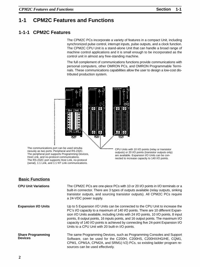
The CPM2C PCs incorporate a variety of features in a compact Unit, includingsynchronized pulse control, interrupt inputs, pulse outputs, and a clock function.The CPM2C CPU Unit is a stand-alone Unit that can handle a broad range ofmachine control applications and it is small enough to be incorporated as thecontrol unit in almost any free-standing machine.
The full complement of communications functions provide communications withpersonal computers, other OMRON PCs, and OMRON Programmable Termi-nals. These communications capabilities allow the user to design a low-cost dis-tributed production system.
The communications port can be used simulta-neously as two ports: Peripheral and RS-232C.The peripheral port supports Programming Devices,Host Link, and no-protocol communications.The RS-232C port supports Host Link, no-protocol(serial), 1:1 Link, and 1:1 NT Link communications.
CPU Units with 10 I/O points (relay or transistoroutputs) or 20 I/O points (transistor outputs only)are available. Expansion I/O Units can be con-nected to increase capacity to 140 I/O points.
Basic Functions
The CPM2C PCs are one-piece PCs with 10 or 20 I/O points in I/O terminals or abuilt-in connector. There are 3 types of outputs available (relay outputs, sinkingtransistor outputs, and sourcing transistor outputs). All CPM2C PCs requirea 24-VDC power supply.
Up to 5 Expansion I/O Units can be connected to the CPU Unit to increase thePC’s I/O capacity to a maximum of 140 I/O points. There are 10 different Expan-sion I/O Units available, including Units with 24 I/O points, 10 I/O points, 8 inputpoints, 8 output points, 16 inputs points, and 16 output points. The maximum I/Ocapacity of 140 I/O points is achieved by connecting five 24-point Expansion I/OUnits to a CPU Unit with 20 built-in I/O points.
The same Programming Devices, such as Programming Consoles and SupportSoftware, can be used for the C200H, C200HS, C200HX/HG/HE, CQM1,CPM1, CPM1A, CPM2A, and SRM1(-V2) PCs, so existing ladder program re-sources can be used effectively.
CPU Unit Variations
Expansion I/O Units
Share ProgrammingDevices

1-1SectionCPM2C Features and Functions
3
Built-in Motor Control CapabilitySynchronized pulse control provides an easy way to synchronize the operationof a peripheral piece of equipment with the main equipment. The output pulsefrequency can be controlled as some multiple of the input pulse frequency, al-lowing the speed of a peripheral piece of equipment (such as a supply conveyor)to be synchronized with the speed of the main piece of equipment.
Encoder
CPM2C
Motor driver Motor
Pulses are output as a fixed multiple of the input frequency.
The CPM2C has a two kinds of high-speed counter inputs. The high-speedcounter input has a response frequency of 20 kHz/5 kHz and the interrupt inputs(in counter mode) have a response frequency of 2 kHz.The single high-speed counter can be used in any one of the four input modes:differential phase mode (5 kHz), pulse plus direction input mode (20 kHz), up/down pulse mode (20 kHz), or increment mode (20 kHz). Interrupts can be trig-gered when the count matches a set value or falls within a specified range.The interrupt inputs (counter mode) can be used for incrementing counters ordecrementing counters (2 kHz) and trigger an interrupt (executing the interruptprogram) when the count matches the target value. Four interrupt inputs can beused in the 20-point CPU Units and two interrupt inputs can be used in the10-point CPU Units.
CPM2C PCs with transistor outputs have two outputs that can produce 10 Hz to10 kHz pulses (single-phase outputs).When used as single-phase pulse outputs, there can be two outputs with a fre-quency range of 10 Hz to 10 kHz with a fixed duty ratio or 0.1 to 999.9 Hz with avariable duty ratio (0 to 100% duty ratio).When used as pulse plus direction or up/down pulse outputs, there can be justone output with a frequency range of 10 Hz to 10 kHz.
High-speed Input Capabilities for Machine ControlThe 20-point CPU Units have 4 inputs that can be used as interrupt inputs andthe 10-point CPU Units have 2 inputs that can be used as interrupt inputs. Theseinputs are shared with quick-response inputs and interrupt inputs in countermode and have a minimum input signal width of 50 µs and response time of0.3 ms. When an interrupt input goes ON, the main program is stopped and theinterrupt program is executed.
Regardless of the cycle time, the 20-point CPU Units have 4 inputs that can beused as quick-response inputs and the 10-point CPU Units have 2 inputs thatcan be used as quick-response inputs. These inputs are shared with interruptinputs and interrupt inputs in counter mode; they can reliably read input signalswith a signal width as short as 50 µs.
The input time constant for all inputs can be set to 1 ms, 2 ms, 3 ms, 5 ms,10 ms, 20 ms, 40 ms, or 80 ms. The effects of chattering and external noise canbe reduced by increasing the input time constant.
Other FunctionsThe interval timer can be set between 0.5 and 319,968 ms and can be set to gen-erate just one interrupt (one-shot mode) or periodic interrupts (scheduled inter-rupt mode).
Synchronized PulseControl (Transistor Outputs Only)
High-speed Counters andInterrupts
Easy Position Controlwith Pulse Outputs(Transistor Outputs Only)
High-speed InterruptInput Function
Quick-response InputFunction
Stabilizing Input FilterFunction
Interval Timer Interrupts
1-1SectionCPM2C Features and Functions
4
In CPU Units with a built-in clock, the clock (accuracy within 1 minute/month) canbe read from the program to show the current year, month, day, day of the week,and time. The clock can be set from a Programming Device (such as a Program-ming Console) or the time can be adjusted by rounding up or down to the nearestminute.
TIML(––) is a long-term timer that accommodates set values up to 99,990 sec-onds (27 hours, 46 minutes, 30 seconds). When combined with the SECONDSTO HOURS conversion instruction (HMS(––)), the long-term timer provides aneasy way to control equipment scheduling.
Greater Data Handling Capability with Expansion UnitsUp to 4 Analog I/O Units can be mounted to the CPM2C. For each Analog I/OUnit mounted to the Unit, 2 analog input points and 1 analog output point areavailable. By mounting 4 Analog I/O Units, a maximum of 8 analog input pointsand 4 analog output points can be made available. (By using a combination ofthe PID(––) instruction and PWM(––) instruction, time proportional control ispossible.)
• The ranges supported for analog input signals are 0 to 5 V, 0 to 10 V, –10 to10 V, 0 to 20 mA, and 4 to 20 mA, and the resolution is 1/6000 (full scale). Theaverage processing function and power interruption detection function can beused.
• The ranges supported for analog output signals are 1 to 5 V, 0 to 10 V, –10 to10 V, 0 to 20 mA, and 4 to 20 mA, and the resolution is 1/6000 (full scale).
Up to 4 Temperature Sensor Units can be mounted to the CPM2C. There are 2models of Temperature Sensor Unit: One for input from a thermocouple sensorand one for input from a platinum resistance thermometer sensor. There are 2input points on each Temperature Sensor Unit.
• Thermocouple inputs (and measurement ranges): K (–200 to 1,300°C, 0.0 to500.0°C), J (-100 to 850°C, 0.0 to 400.0°C).
• Platinum resistance thermometer inputs (and measurement ranges): Pt100(–200.0 to 650.0°C), JPt100 (–200.0 to 650.0°C).
The CPM2C can be used as a CompoBus/S Slave (with 8 built-in inputs and 8built-in outputs) by connecting a CompoBus/S I/O Link Unit. Up to 5 Compo-Bus/S I/O Link Units can be connected to the CPM2C. In addition to the conven-tional “PC + Remote I/O” type of distributed I/O control, “PC + miniature PC” dis-tributed CPU control is now possible. This means increased modularization,allowing greater standardization of design, improved suitability to special needs,and easier replacement of malfunctioning Units.
Calendar/Clock
Long-term Timer
Analog I/O Supported
Temperature SensorUnits
CompoBus/S I/O LinkUnits
1-1SectionCPM2C Features and Functions
5
Complete Communications Capabilities
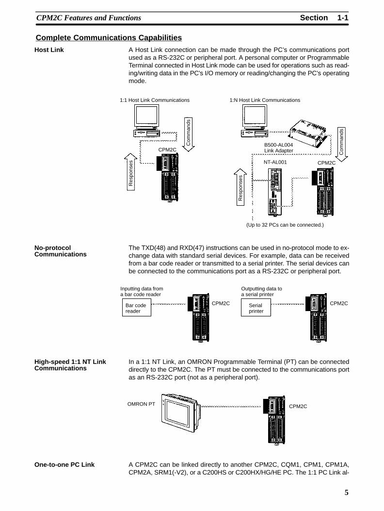
A Host Link connection can be made through the PC’s communications portused as a RS-232C or peripheral port. A personal computer or ProgrammableTerminal connected in Host Link mode can be used for operations such as read-ing/writing data in the PC’s I/O memory or reading/changing the PC’s operatingmode.
1:1 Host Link Communications
CPM2C
1:N Host Link Communications
B500-AL004Link Adapter
CPM2C
(Up to 32 PCs can be connected.)
NT-AL001
Com
man
ds
Res
pons
es
Com
man
ds
Res
pons
es
The TXD(48) and RXD(47) instructions can be used in no-protocol mode to ex-change data with standard serial devices. For example, data can be receivedfrom a bar code reader or transmitted to a serial printer. The serial devices canbe connected to the communications port as a RS-232C or peripheral port.
Inputting data froma bar code reader
Bar codereader
Outputting data toa serial printer
Serialprinter
CPM2C CPM2C
In a 1:1 NT Link, an OMRON Programmable Terminal (PT) can be connecteddirectly to the CPM2C. The PT must be connected to the communications portas an RS-232C port (not as a peripheral port).
OMRON PT CPM2C
A CPM2C can be linked directly to another CPM2C, CQM1, CPM1, CPM1A,CPM2A, SRM1(-V2), or a C200HS or C200HX/HG/HE PC. The 1:1 PC Link al-
Host Link
No-protocolCommunications
High-speed 1:1 NT LinkCommunications
One-to-one PC Link

1-1SectionCPM2C Features and Functions
6
lows automatic data link connections. The PC must be connected to the commu-nications port as an RS-232C port (not as a peripheral port).
CPM2C CPM2C
The CPM1-EMU01-V1 Expansion Memory Unit is a program loader for small-size or micro PCs. Using the CPM1-EMU01-V1, simple on-site transfer of userprograms and data memory is possible with PCs.
Expansion Memory Unit
Indicator
UPLOAD+DM Button UPLOAD Button
EEPROM
CPM2C-CN111
CS1W-CN114
CPM2C
CPM2C
CPM2C-CIF01
1-1-2 Overview of CPM2C Functions
Main function Variations/DetailsInterrupts Interrupt inputs
2 inputs in CPU Units with 10 I/O points, 4 inputs in CPU Units with 20 I/O points
Response time: 0.3 msInterval timer interrupts1 input
Scheduled interrupts
Set value: 0.5 to 319,968 msPrecision: 0.1 ms
One-shot interrupt
High-speed counters High-speed counter No interrupt1 input, see note 1.
Differential phase mode (5 kHz)Pulse plus direction input mode (20 kHz)Up/down input mode (20 kHz)Increment mode (20 kHz)
Count-check interrupt
(An interrupt can be generated when thecount equals the set value or the countlies within a preset range.)
Interrupt inputs (counter mode)2 inputs in CPU Units with 10 I/O points,
No interrupt
4 inputs in CPU Units with 20 I/O points
Incrementing counter (2 kHz)Decrementing counter (2 kHz)
Count-up interrupt
Expansion Memory Unit
1-2SectionSystem Configurations
7
Main function Variations/Details
Pulse outputs 2 outputs:Single-phase pulse output without acceleration/deceleration (See note 2.)10 Hz to 10 kHz
2 outputs:Variable duty ratio pulse output (See note 2.)0.1 to 999.9 Hz, duty ratio 0 to 100%
1 output:Pulse output with trapezoidal acceleration/deceleration (See note 2.)Pulse plus direction output, up/down pulse output, 10 Hz to 10 kHz
Synchronized pulse control 1 point, see notes 1 and 2.
Input frequency range: 10 to 500 Hz, 20 Hz to 1 kHz, or 300 Hz to 20 kHzOutput frequency range: 10 Hz to 10 kHz
Quick-response input 2 inputs in CPU Units with 10 I/O points, 4 inputs in CPU Units with 20 I/O points
Minimum input signal width: 50 µs
Input time constant Determines the input time constant for all inputs. (Settings: 1, 2, 3, 5, 10, 20, 40, or 80 ms)
Calendar/Clock Shows the current year, month, day of the week, day of the month, hour, minute, andsecond.
Expansion Unit functions Analog I/O functions using CPM2C-MAD11 Analog I/O Unit
Two analog inputs: Input range of 0 to 5 V, 1 to 5 V, 0 to 10 V, –10 to 10 V, 0 to 20 mA,or 4 to 20 mAOne analog output: Output range of 1 to 5 V, 0 to 10 V, –10 to 10 V, 0 to 20 mA, or 4 to20 mA
Temperature sensing functions using CPM2C-TS001/101 Temperature Sensor Unit
Thermocouple input (measurement range): K (-200 to 1,300°C) K (0.0 to 500.0°C)
J (–100 to 850°C)J (0.0 to 400.0°C)
Platinum resistance thermometer (measurement range): Pt100 (–200.0 to 650.0°C)JPt100 (–200.0 to 650.0°C)
CompoBus/S Slave functions using CPM2C-SRT21 CompoBus/S I/O Link Unit
Data exchange with the Master Unit via 8 inputs and 8 outputs.
Note 1. This input is shared by the high-speed counter and synchronized pulse con-trol functions.
2. This output is shared by the pulse output and synchronized pulse controlfunctions. These functions can be used with transistor outputs only.
1-2 System Configurations
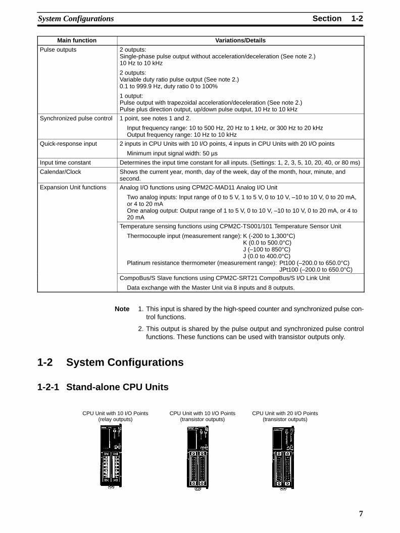
1-2-1 Stand-alone CPU Units
CPU Unit with 10 I/O Points(relay outputs)
CPU Unit with 10 I/O Points(transistor outputs)
CPU Unit with 20 I/O Points(transistor outputs)
1-2SectionSystem Configurations
8
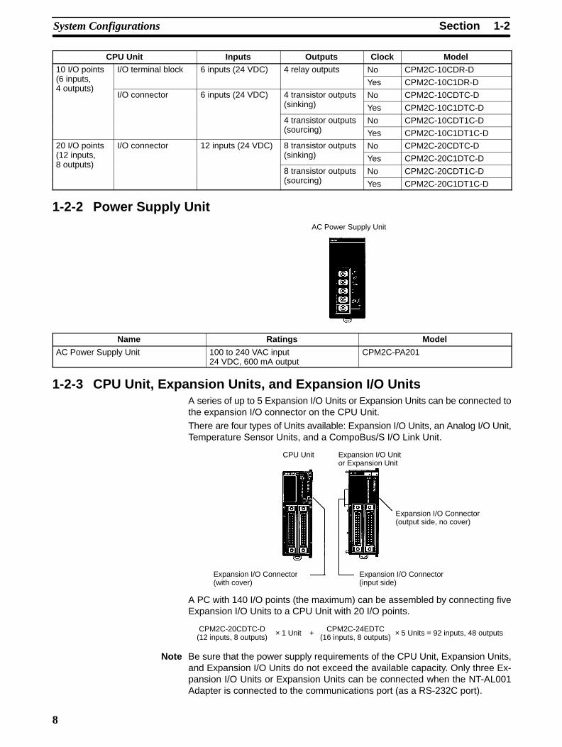
CPU Unit Inputs Outputs Clock Model10 I/O points I/O terminal block 6 inputs (24 VDC) 4 relay outputs No CPM2C-10CDR-D(6 inputs, Yes CPM2C-10C1DR-D4 outputs)
I/O connector 6 inputs (24 VDC) 4 transistor outputs No CPM2C-10CDTC-D(sinking) Yes CPM2C-10C1DTC-D
4 transistor outputs No CPM2C-10CDT1C-D(sourcing) Yes CPM2C-10C1DT1C-D
20 I/O points I/O connector 12 inputs (24 VDC) 8 transistor outputs No CPM2C-20CDTC-D(12 inputs, (sinking) Yes CPM2C-20C1DTC-D8 outputs)
8 transistor outputs No CPM2C-20CDT1C-D(sourcing) Yes CPM2C-20C1DT1C-D
1-2-2 Power Supply UnitAC Power Supply Unit
Name Ratings Model
AC Power Supply Unit 100 to 240 VAC input24 VDC, 600 mA output
CPM2C-PA201
1-2-3 CPU Unit, Expansion Units, and Expansion I/O UnitsA series of up to 5 Expansion I/O Units or Expansion Units can be connected tothe expansion I/O connector on the CPU Unit.
There are four types of Units available: Expansion I/O Units, an Analog I/O Unit,Temperature Sensor Units, and a CompoBus/S I/O Link Unit.
Expansion I/O Connector(with cover)
Expansion I/O Unitor Expansion Unit
CPU Unit
Expansion I/O Connector(input side)
Expansion I/O Connector(output side, no cover)
A PC with 140 I/O points (the maximum) can be assembled by connecting fiveExpansion I/O Units to a CPU Unit with 20 I/O points.
CPM2C-20CDTC-D(12 inputs, 8 outputs)
CPM2C-24EDTC(16 inputs, 8 outputs)× 1 Unit + × 5 Units = 92 inputs, 48 outputs
Note Be sure that the power supply requirements of the CPU Unit, Expansion Units,and Expansion I/O Units do not exceed the available capacity. Only three Ex-pansion I/O Units or Expansion Units can be connected when the NT-AL001Adapter is connected to the communications port (as a RS-232C port).

1-2SectionSystem Configurations
9
Expansion I/O Units
Expansion I/O Unit with10 relay output points
Expansion I/O Unit with24 transistor output points
Expansion I/O Unit with8 DC input points
Expansion I/O Unit with16 DC input points
Expansion I/O Unit with8 relay output points
Expansion I/O Unit with8 transistor output points
Expansion I/O Unit with16 transistor output points
Unit Inputs Outputs Model
10 I/O points
6 inputs, 4 outputs
I/O terminals 6 inputs (24 VDC) 4 relay outputs CPM2C-10EDR
24 I/O points I/O connector 16 inputs (24 VDC) 8 transistor outputs(sinking)
CPM2C-24EDTC
16 inputs, 8 outputs8 transistor outputs(sourcing)
CPM2C-24EDT1C
8 input points I/O connector 8 inputs (24 VDC) --- CPM2C-8EDC
16 input points I/O connector 16 inputs (24 VDC) --- CPM2C-16EDC
8 output points I/O terminals --- 8 relay outputs CPM2C-8ER
I/O connector --- 8 transistor outputs(sinking)
CPM2C-8ETC
--- 8 transistor outputs(sourcing)
CPM2C-8ET1C
16 output points I/O connector --- 16 transistor outputs(sinking)
CPM2C-16ETC
--- 16 transistor outputs(sourcing)
CPM2C-16ET1C
Note Be sure that the power supply requirements of the CPU Unit, Expansion Units,and Expansion I/O Units do not exceed the available capacity. Only three Ex-pansion I/O Units and Expansion Units can be connected when the NT-AL001Adapter is connected to the communications port (as a RS-232C port).
1-2SectionSystem Configurations
10
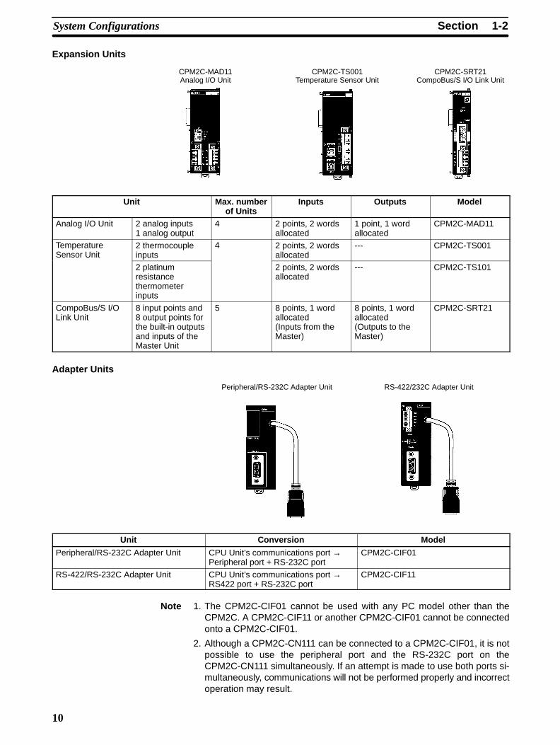
Expansion Units
CPM2C-MAD11Analog I/O Unit
CPM2C-TS001Temperature Sensor Unit
CPM2C-SRT21CompoBus/S I/O Link Unit
Unit Max. numberof Units
Inputs Outputs Model
Analog I/O Unit 2 analog inputs1 analog output
4 2 points, 2 wordsallocated
1 point, 1 wordallocated
CPM2C-MAD11
TemperatureSensor Unit
2 thermocoupleinputs
4 2 points, 2 wordsallocated
--- CPM2C-TS001
2 platinumresistancethermometerinputs
2 points, 2 wordsallocated
--- CPM2C-TS101
CompoBus/S I/OLink Unit
8 input points and8 output points forthe built-in outputsand inputs of theMaster Unit
5 8 points, 1 wordallocated(Inputs from theMaster)
8 points, 1 wordallocated(Outputs to theMaster)
CPM2C-SRT21
Adapter Units
Peripheral/RS-232C Adapter Unit RS-422/232C Adapter Unit
Unit Conversion Model
Peripheral/RS-232C Adapter Unit CPU Unit’s communications port →Peripheral port + RS-232C port
CPM2C-CIF01
RS-422/RS-232C Adapter Unit CPU Unit’s communications port →RS422 port + RS-232C port
CPM2C-CIF11
Note 1. The CPM2C-CIF01 cannot be used with any PC model other than theCPM2C. A CPM2C-CIF11 or another CPM2C-CIF01 cannot be connectedonto a CPM2C-CIF01.
2. Although a CPM2C-CN111 can be connected to a CPM2C-CIF01, it is notpossible to use the peripheral port and the RS-232C port on theCPM2C-CN111 simultaneously. If an attempt is made to use both ports si-multaneously, communications will not be performed properly and incorrectoperation may result.

1-3SectionStructure and Operation
11
1-3 Structure and Operation
1-3-1 CPU Unit StructureThe following diagram shows the internal structure of the CPU Unit.
Externalinputdevices
I/O memory
Program
PC Setup
Commu-nicationsport
Settings
Settings
Settings
Externaloutputdevices
Communicationsswitches
Inpu
t circ
uits
Out
put c
ircui
ts
The program reads and writes data in this memory area during execution. Part ofthe I/O memory contains the bits that reflect the status of the PC’s inputs andoutputs. Parts of the I/O memory are cleared when the power is turned ON andother parts are retained.
Note Refer to Section 3 Memory Areas in the Programming Manual (W353) for moredetails on I/O memory.
This is the program written by the user. The CPM2C executes the program cycli-cally. (Refer to 1-3-5 Cyclic Operation and Interrupts for details.)
The program can be divided broadly into two parts: the “main program” that isexecuted cyclically and the “interrupt programs” that are executed only when thecorresponding interrupt is generated.
The PC Setup contains various startup and operating parameters. The PC Set-up parameters can be changed from a Programming Device only; they cannotbe changed from the program.
Some parameters are accessed only when PC’s power supply is turned ON andothers are accessed regularly while the power is ON. It will be necessary to turnthe power OFF and then ON again to enable a new setting if the parameter isaccessed only when the power is turned ON.
Note Refer to Section 1 PC Setup in the Programming Manual (W353) for more de-tails.
The Communications Switches determine whether the peripheral port andRS-232C port connected through the communications port operate with thestandard communications settings or the communications settings in the PCSetup.
I/O Memory
Program
PC Setup
CommunicationsSwitches
!
1-3SectionStructure and Operation
12
1-3-2 Operating ModesCPM2C CPU Units have 3 operating modes: PROGRAM, MONITOR, and RUN.
The program cannot be executed in PROGRAM mode. This mode is used toperform the following operations in preparation for program execution.
• Changing initial/operating parameters such as those in the PC Setup
• Writing, transferring, or checking the program
• Checking wiring by force-setting and force-resetting I/O bits
Caution The PC continues to refresh I/O bits even if the PC is in PROGRAM mode, sodevices connected to output points on the CPU Unit, Expansion Units, or Expan-sion I/O Units may operate unexpectedly if the corresponding output bit is turnedON by changing the contents of I/O memory.
The program is executed in MONITOR mode and the following operations canbe performed from a Programming Device. In general, MONITOR mode is usedto debug the program, test operation, and make adjustments.
• Online editing
• Monitoring I/O memory during operation
• Force-setting/force-resetting I/O bits, changing set values, and changing pres-ent values during operation
The program is executed at normal speed in RUN mode. Operations such asonline editing, force-setting/force-resetting I/O bits, and changing set values/present values cannot be performed in RUN mode, but the status of I/O bits canbe monitored.
1-3-3 Operating Mode at StartupThe operating mode of the CPM2C when the power is turned ON depends uponthe PC Setup settings and the Programming Console’s mode switch setting if aProgramming Console is connected.
PC Setup setting Operating mode
Word Bits SettingDM 6600 08 to 15 00 See note.
01 Startup mode is the same as the operating modebefore power was interrupted.
02 Startup mode is determined by bits 00 to 07.
00 to 07 00 PROGRAM mode
01 MONITOR mode
02 RUN mode
Note The startup mode depends upon the setting of Communications Switch 2 andthe Programming Device connected to the communications port (peripheralport).
Programming Device Switch 2 OFF Switch 2 ON
None PROGRAM mode RUN mode (seenote 2)
Programming Console Operating mode set on theProgramming Console’smode switch
PROGRAM mode(see note 1)
Other device PROGRAM mode (see note 1)
PROGRAM mode
Note 1. The CPM2C will not be able to communicate with the Programming Devicein these cases.
PROGRAM Mode
MONITOR Mode
RUN Mode

1-3SectionStructure and Operation
13
2. When the power is turned ON, the CPM2C will start in the RUN mode onlywhen the RS-232C cable is connected to the communications port withswitch 2 set to ON.
1-3-4 PC Operation at StartupThe time required for startup initialization depends on several factors, such asthe operating conditions (including power supply voltage, system configuration,and ambient temperature) and the program contents.
Power OFF OperationMinimum Power Supply VoltageThe PC will stop and all outputs will be turned OFF if the power supply voltagefalls below 85% of the rated value.
Momentary Power InterruptionA power interruption will not be detected and CPU Unit operation will continue ifthe power interruption lasts less than 2 ms.
A power interruption may or may not be detected for power interruptions some-what longer than 2 ms.
When a power interruption is detected, the CPU Unit will stop operating and alloutputs will be turned OFF.
Automatic ResetOperation will restart automatically when the power supply voltage is restored tomore than 85% of the rated voltage.
Timing Chart of Power OFF OperationThe power interruption detection time is the time required for a power interrup-tion to be detected after the power supply voltage drops below 85% of the ratedvalue.
1, 2, 3... 1. Minimum power interruption detection timePower interruptions that are shorter than 2 ms will not be detected.
2. Undetermined additional timePower interruptions only slightly longer than the minimum power interrup-tion time may not be detected.
85% of rated voltage
Program execution
CPU reset signal
Detection ofpower interruption
Executing Stopped
1. Minimum time 2. Additionaltime
CPU Unit operation willcontinue if voltage isrestored in this region.
CPU Unit operation maycontinue if voltage isrestored in this region.
Note If the power supply voltage fluctuates around 85% of the PC’s rated voltage, PCoperation may stop and restart repeatedly. When repeated stopping and starting
Time Required forInitialization
1-3SectionStructure and Operation
14
will cause problems with the controlled system, set up a protective circuit suchas a circuit that shuts OFF the power supply to sensitive equipment until thepower supply voltage returns to the rated value.
1-3-5 Cyclic Operation and Interrupts
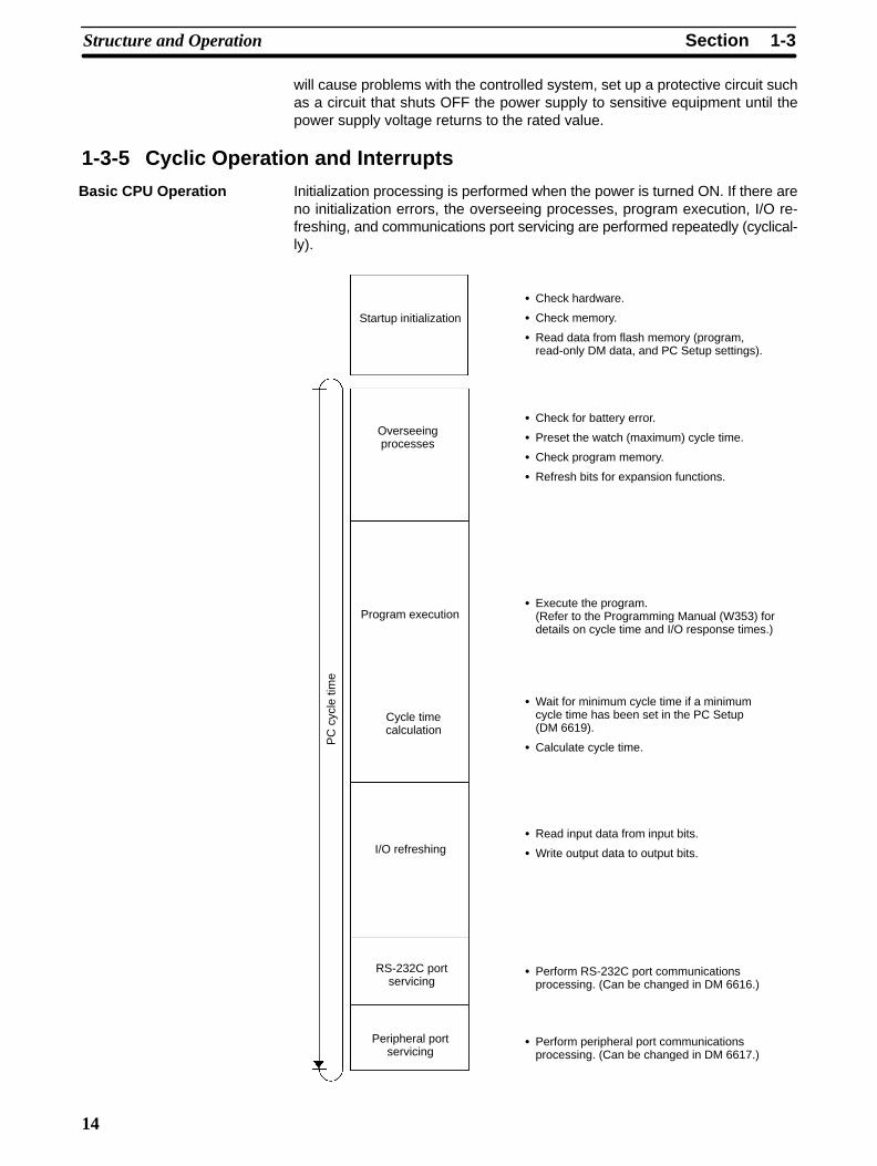
Initialization processing is performed when the power is turned ON. If there areno initialization errors, the overseeing processes, program execution, I/O re-freshing, and communications port servicing are performed repeatedly (cyclical-ly).
Startup initialization
Overseeingprocesses
Program execution
Cycle timecalculation
I/O refreshing
RS-232C portservicing
Peripheral portservicing
Check hardware.
Check memory.
Read data from flash memory (program,read-only DM data, and PC Setup settings).
Check for battery error.
Preset the watch (maximum) cycle time.
Check program memory.
Refresh bits for expansion functions.
Execute the program.(Refer to the Programming Manual (W353) fordetails on cycle time and I/O response times.)
Wait for minimum cycle time if a minimumcycle time has been set in the PC Setup(DM 6619).
Calculate cycle time.
Read input data from input bits.
Write output data to output bits.
Perform RS-232C port communicationsprocessing. (Can be changed in DM 6616.)
Perform peripheral port communicationsprocessing. (Can be changed in DM 6617.)
PC
cyc
le ti
me
Basic CPU Operation
1-3SectionStructure and Operation
15
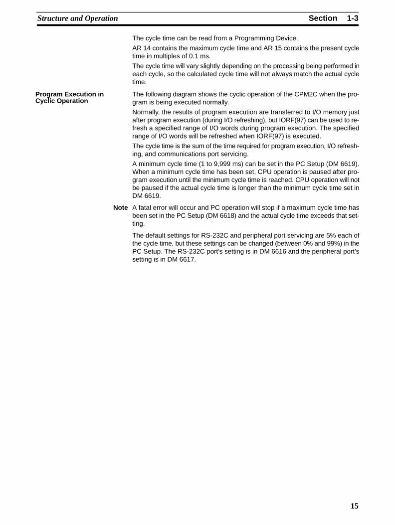
The cycle time can be read from a Programming Device.
AR 14 contains the maximum cycle time and AR 15 contains the present cycletime in multiples of 0.1 ms.
The cycle time will vary slightly depending on the processing being performed ineach cycle, so the calculated cycle time will not always match the actual cycletime.
The following diagram shows the cyclic operation of the CPM2C when the pro-gram is being executed normally.
Normally, the results of program execution are transferred to I/O memory justafter program execution (during I/O refreshing), but IORF(97) can be used to re-fresh a specified range of I/O words during program execution. The specifiedrange of I/O words will be refreshed when IORF(97) is executed.
The cycle time is the sum of the time required for program execution, I/O refresh-ing, and communications port servicing.
A minimum cycle time (1 to 9,999 ms) can be set in the PC Setup (DM 6619).When a minimum cycle time has been set, CPU operation is paused after pro-gram execution until the minimum cycle time is reached. CPU operation will notbe paused if the actual cycle time is longer than the minimum cycle time set inDM 6619.
Note A fatal error will occur and PC operation will stop if a maximum cycle time hasbeen set in the PC Setup (DM 6618) and the actual cycle time exceeds that set-ting.
The default settings for RS-232C and peripheral port servicing are 5% each ofthe cycle time, but these settings can be changed (between 0% and 99%) in thePC Setup. The RS-232C port’s setting is in DM 6616 and the peripheral port’ssetting is in DM 6617.
Program Execution inCyclic Operation

1-3SectionStructure and Operation
16
Refer to Section 7 PC Operations and Processing Time in the ProgrammingManual (W353) for more details and precautions on the cycle time.
Cycletime
Overseeing processes
Main program
I/O refreshing
RS-232C port servicing
Peripheral port servicing
If a minimum cycle time has beenset in DM 6619, CPU operation ispaused until the minimum cycletime is reached.
The servicing time can be setin DM 6616.The servicing time can be setin DM 6617.
When an interrupt is generated during execution of the main program, main pro-gram execution is interrupted immediately and the interrupt program is execut-ed. The following diagram shows the cyclic operation of the CPM2C when aninterrupt program is executed.
Normally, the results of interrupt program execution are transferred to I/Omemory just after program execution (during I/O refreshing), but IORF(97) canbe used to refresh a specified range of I/O words during execution of the inter-rupt program. The specified range of I/O words will be refreshed when IORF(97)is executed.
The normal cycle time is extended by the time required for execution of the inter-rupt program.
Interrupt ProgramExecution

!
1-3SectionStructure and Operation
17
Refer to Section 7 PC Operations and Processing Time in the ProgrammingManual (W353) for more details and precautions on the cycle time.
Cycletime
Overseeing processes
Main program
I/O refreshing
RS-232C port servicing
Peripheral port servicing
Interrupt generated.
Interrupt program
Caution Although IORF(97) can be used in interrupt subroutines, you must be careful ofthe interval between IORF(97) executions. If IORF(97) is executed too fre-quently, a fatal system error may occur (FALS 9F), stopping operation. The inter-val between executions of IORF(97) should be at least 1.3 ms + total executiontime of the interrupt subroutine.
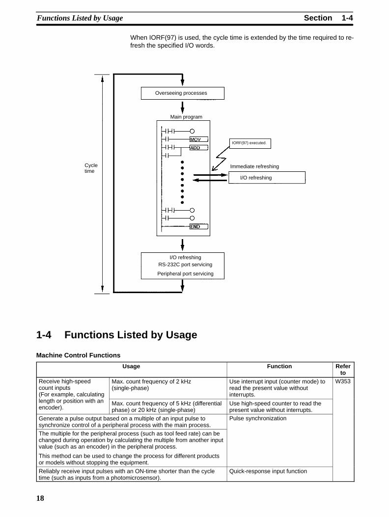
IORF(97) can be executed in the program to refresh a specified range of I/Owords. The specified I/O words will be refreshed when IORF(97) is executed.
IORF(97) can be used to refresh I/O from the main program or the interrupt pro-gram.
Immediate Refreshing
1-4SectionFunctions Listed by Usage
18
When IORF(97) is used, the cycle time is extended by the time required to re-fresh the specified I/O words.
Cycletime
Overseeing processes
Main program
I/O refreshingRS-232C port servicing
Peripheral port servicing
IORF(97) executed.
Immediate refreshing
I/O refreshing
1-4 Functions Listed by Usage
Machine Control Functions
Usage Function Referto
Receive high-speedcount inputs(For example, calculating
Max. count frequency of 2 kHz(single-phase)
Use interrupt input (counter mode) toread the present value withoutinterrupts.
W353
length or position with anencoder).
Max. count frequency of 5 kHz (differentialphase) or 20 kHz (single-phase)
Use high-speed counter to read thepresent value without interrupts.
Generate a pulse output based on a multiple of an input pulse tosynchronize control of a peripheral process with the main process.
Pulse synchronization
The multiple for the peripheral process (such as tool feed rate) can bechanged during operation by calculating the multiple from another inputvalue (such as an encoder) in the peripheral process.
This method can be used to change the process for different productsor models without stopping the equipment.
Reliably receive input pulses with an ON-time shorter than the cycletime (such as inputs from a photomicrosensor).
Quick-response input function

1-4SectionFunctions Listed by Usage
19
Usage Referto
Function
Interrupt functions Execute a special process very quicklywhen an input goes ON.(For example, operating a cutter when aninterrupt input is received from a ProximitySwitch or Photoelectric Switch.)
Interrupt input (interrupt input mode) W353
Count input ON pulses and execute aspecial process very quickly when thecount reaches the preset value.(For example, stopping the supply feedwhen a preset number of workpieces havepassed through the system.)
Interrupt input (counter mode)
Execute a special process at a presetcount value.(For example, cutting material veryprecisely at a given length.)
High-speed counter interruptgenerated when the count matchesthe set value.
Execute a special process when the countis within a preset range.(For example, sorting material very quicklywhen it is within a given length range.)
High-speed counter interruptgenerated when the count is within theset range.
Execute a special process when a timertimes out.(For example, stopping a conveyor at veryprecise time (independent of the cycletime) after the workpiece is detected.)
Interval timer interrupt(One-shot mode)
Repeat a special process at regularintervals.(For example, the speed of a sheet feedercan be monitored by measuring the inputsignal from an encoder at regular intervalsand calculating the speed.)
Interval timer interrupt(Scheduled interrupt mode)
Perform simple positioning by outputting pulses to a motor driver thataccepts pulse-train inputs.
Pulse output function
Receive an analog input and output an analog output. Analog I/O Unit(Connect the Analog I/O Unit to theCPU Unit.)
Receive temperature sensor input directly at the PC. Temperature Sensor Unit(Connect the Temperature SensorUnit to the CPU Unit.)
Reduce required wiring, space, and PC load by controlling equipmentwith a few low-capacity PCs dispersed near the equipment rather thana single, large, centralized PC.(Create a remote I/O link with a CompoBus/S Master and CompoBus/SSlaves.)
CompoBus/S I/O Link Unit(Connect the CompoBus/S I/O LinkUnit to the CPU Unit.)
Basic Functions
Usage Function Referto
Set the cycle time to a fixed interval. Set a minimum (fixed) cycle time in the PC Setup. W353
Stop PC operation when the cycle time exceeds amaximum setting.
Set a maximum (watch) cycle time in the PC Setup.
Keep all outputs ON when PC operation stops. Turn ON the IOM Hold Bit (SR 25212).
Retain the contents of I/O memory when startingoperation.
Turn ON the IOM Hold Bit (SR 25212).
Retain the contents of I/O memory when the PC isturned ON.
Turn ON the IOM Hold Bit (SR 25212) and set the PCSetup (DM 6601) so that the status of the IOM Hold Bitis maintained at startup.
Eliminate effects from chattering and external noise. Set a longer input time constant in the PC Setup.
1-5SectionComparison with the CPM1A and CPM2A
20
Maintenance Functions
Usage Function Referto
Record data with time-stamp. Clock/calendar function W353
Establish user-defined errors for desired inputconditions. (Fatal and non-fatal errors can be defined.)
FAL(06) defines non-fatal errors. (PC operationcontinues.)
FALS(07) defines fatal errors. (PC operation stops.)
Read the number of power interruptions. The number of power interruptions is stored in AR 23.
Set the startup operating mode. Set the startup operating mode in the PC Setup(DM 6600).
Communications Functions
Usage Function Referto
Read/write I/O memory data and change the operatingmode from a host computer.
Host Link communications (Set the communicationsmode to Host Link in the PC Setup.)
W353
Connect to a serial device such as a bar code readeror serial printer.
No-protocol communications (Set the communicationsmode to no-protocol in the PC Setup.)
Make a high-speed connection with an OMRONProgrammable Terminal.
1:1 NT Link (Set the communications mode to 1:1 NTLink in the PC Setup.)
Make a PC-PC data link connection with anotherCPM2C, or a CPM1, CPM1A, CPM2A, SRM1, CQM1,C200HS, or C200HX/HG/HE PC.
1:1 PC Link (Set the communications mode to 1:1 PCLink in the PC Setup.)
Connect a Programming Console. Connect the Programming Console to the peripheralport via the communications port. (Turn OFFCommunications Switch 2.)
Page114
Connect a personal computer running SYSMACSupport Software (SSS) or SYSMAC-CPT SupportSoftware.
The computer can be connected to the peripheral portor RS-232C port via the communications port.(Turn OFF Communications Switch 2.)
Page108
Monitor equipment with a Programmable Terminal andprogram the PC with a Programming Device.
The RS-232C port and peripheral port can be usedsimultaneously via the communications port.
W353Page108,114
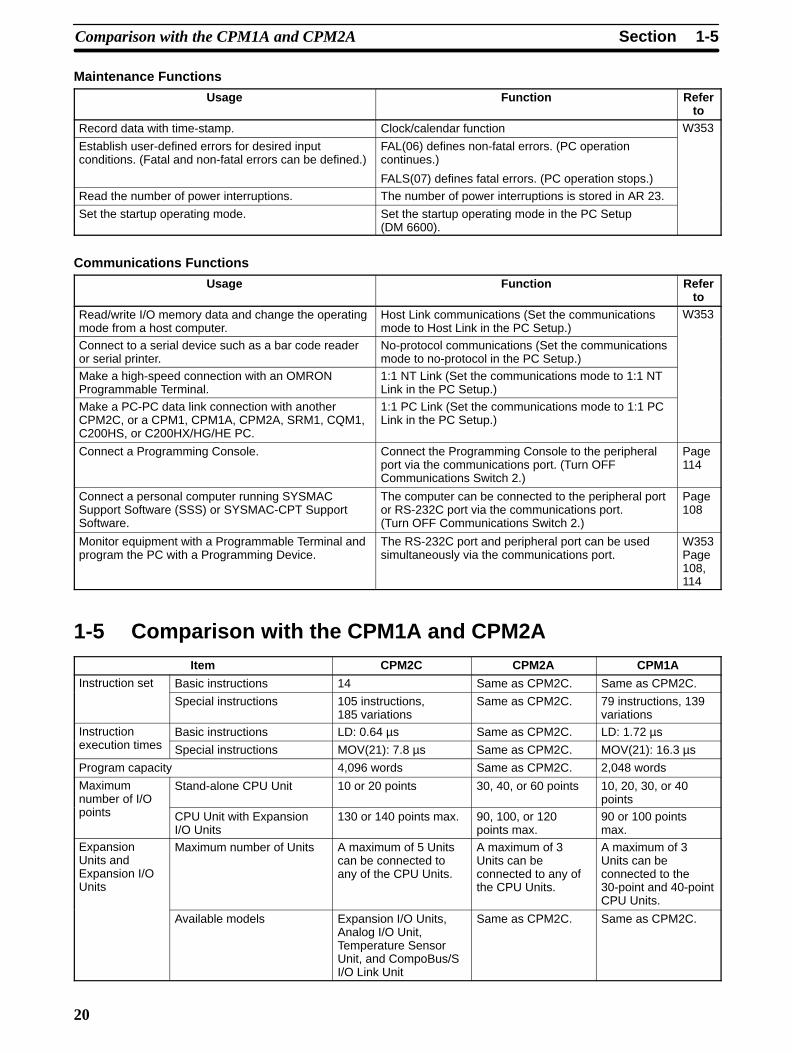
1-5 Comparison with the CPM1A and CPM2AItem CPM2C CPM2A CPM1A
Instruction set Basic instructions 14 Same as CPM2C. Same as CPM2C.
Special instructions 105 instructions,185 variations
Same as CPM2C. 79 instructions, 139variations
Instruction Basic instructions LD: 0.64 µs Same as CPM2C. LD: 1.72 µsexecution times Special instructions MOV(21): 7.8 µs Same as CPM2C. MOV(21): 16.3 µs
Program capacity 4,096 words Same as CPM2C. 2,048 words
Maximumnumber of I/O
Stand-alone CPU Unit 10 or 20 points 30, 40, or 60 points 10, 20, 30, or 40points
points CPU Unit with ExpansionI/O Units
130 or 140 points max. 90, 100, or 120points max.
90 or 100 pointsmax.
ExpansionUnits andExpansion I/OUnits
Maximum number of Units A maximum of 5 Unitscan be connected toany of the CPU Units.
A maximum of 3Units can beconnected to any ofthe CPU Units.
A maximum of 3Units can beconnected to the30-point and 40-pointCPU Units.
Available models Expansion I/O Units,Analog I/O Unit,Temperature SensorUnit, and CompoBus/SI/O Link Unit
Same as CPM2C. Same as CPM2C.

1-5SectionComparison with the CPM1A and CPM2A
21
Item CPM1ACPM2ACPM2CI/O memory Input bits IR 00000 to IR 00915 Same as CPM2C. Same as CPM2C.
Output bits IR 01000 to IR 01915 Same as CPM2C. Same as CPM2C.
Work bits 928 bits:IR 02000 to IR 04915,IR 20000 to IR 22715
Same as CPM2C. 512 bits:IR 20000 to IR 23115
SR (Special Relay) area 448 bits:SR 22800 to SR 25515
Same as CPM2C. 384 bits:SR 23200 to SR25515
TR (Temporary Relay) area 8 bits: TR0 to TR7 Same as CPM2C. Same as CPM2C.
HR (Holding Relay) area 320 bits:HR 0000 to HR 1915
Same as CPM2C.
AR (Auxiliary Relay) area 384 bits:AR 0000 to AR 2315
Same as CPM2C. 256 bits:AR 0000 to AR 1515
LR (Link Relay) area 256 bits:LR 0000 to LR 1515
Same as CPM2C. Same as CPM2C.
Timer/Counter area 256 bits:TIM/CNT 000 toTIM/CNT 255
Same as CPM2C. 128 bits:TIM/CNT 0 toTIM/CNT 127
DM (DataMemory) area
Read/writearea
2,048 words(DM 0000 to DM 2047)
Same as CPM2C. 1,024 words(DM 0000 toDM 1023)
Read-onlyarea
456 words(DM 6144 to DM 6599)
Same as CPM2C. Same as CPM2C.
PC Setup 56 words(DM 6600 to DM 6655)
Same as CPM2C. Same as CPM2C.
Memory backup Program area, read-only DMarea (including PC Setup)
Flash memory backup Same as CPM2C. Same as CPM2C.
Read/write DM area, HRarea, AR area, and counters
CPU Unit with clock:Internal battery backup(2-year lifetime at 25°C,replaceable)
CPU Unit without clock:Capacitor backup(10-day backup at25°C) or optionalbattery backup (2 yearsat 25°C, replaceable)
Internal batterybackup(5-year lifetime at25°C, replaceable)
Capacitor backup(20-day backup at25°C)
Interrupt inputs (interrupt input mode) 4 (20-point CPU Unit),2 (10-point CPU Unit)
4 4
Interrupt inputs(counter mode)
Counter mode Incrementing counterDecrementing counter
Same as CPM2C. Decrementingcounter
Counter upper limit 2 kHz Same as CPM2C. 1 kHz
SR 244 to SR 247 Contains counter PV. Same as CPM2C. Contains counterPV–1.
Method(s) to read counterPV
Read SR 244 toSR 247.Execute PRV(62).
Same as CPM2C. Read SR 244 toSR 247.(Counter PV – 1)
Method to change counterPV
Execute INI(61). Same as CPM2C. Not supported.
Interval timer One-shot mode Yes Same as CPM2C. Same as CPM2C.
Scheduled interrupt mode Yes Same as CPM2C. Same as CPM2C.

1-5SectionComparison with the CPM1A and CPM2A
22
Item CPM2C/CPM2A CPM1AQuick-responseinputs
Setting the quick-responsefunction
PC Setup PC Setup and INT(89)(Unmask interrupt input.)
INT(89) (Mask) Not supported (ignored) Supported.
INT(89) (Read mask) Reads mask status. Reads result of masksetting.
INT(89) (Clear) Not supported (ignored) Supported.
Minimum pulse width 50 µs min. 200 µs min.
High-speedcounter
Count mode Differential-phase (up/down) modePulse plus direction modeUp/down pulse modeIncrement mode
Differential-phase(up/down) modeIncrement mode
Max. counter frequency 5 kHz in differential-phase (up/down)mode
20 kHz in pulse plus direction mode,up/down pulse mode, and incrementmode
2.5 kHz indifferential-phase(up/down) mode,5 kHz in increment mode
Counter PV range –8,388,608 to 8,388,607 indifferential-phase (up/down) mode, pulseplus direction mode, and up/down pulsemode
0 to 16,777,215 in increment mode
–32,768 to 32,767 indifferential-phase(up/down) mode
0 to 65,535 in incrementmode
Check when registeringtarget value match table
Same direction, same SV not possible Same direction, same SVpossible
Method used to referencethe target value matchinterrupt table
Comparison of all values in the table,regardless of order of appearance in table
Comparison in order ofappearance in table
Reading range-comparisonresults
Check AR 1100 to AR 1107 or executePRV(62).
Check AR 1100 toAR 1107.
Reading status Check AR 1108 (comparison in progress),check AR 1109 (high-speed counter PVoverflow/underflow), or execute PRV(62).
---
Pulse synchronization Supported. Not supported.
Pulse outputcontrol
Trapezoidal acceleration/deceleration
Supported with ACC(––). The initialfrequency can be set.
Not supported.
PWM(––) output Supported. Not supported.
Number of simultaneouspulse outputs
2 max. 1 max.
Maximum frequency 10 kHz max. 2 kHz max.
Minimum frequency 10 Hz 20 Hz
Pulse output quantity –16,777,215 to 16,777,215 0 to 16,777,215
Direction control Supported. Not supported.
Positioning to absolutepositions
Supported. Not supported.
Bit status while pulses arebeing output
No effect Turned ON/OFF by pulseoutput
Reading PV Read SR 228 through SR 231 or executePRV(62).
Not supported.
Resetting PV Supported. Not supported.
Status outputs Accelerating/deceleratingPV overflow/underflowPulse quantity setPulse output completedPulse output status
Pulse output status
1-5SectionComparison with the CPM1A and CPM2A
23
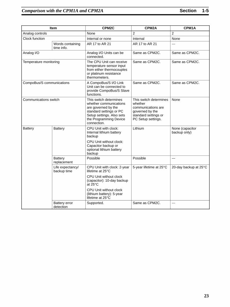
Item CPM2C CPM2A CPM1A
Analog controls None 2 2
Clock function Internal or none Internal None
Words containingtime info.
AR 17 to AR 21 AR 17 to AR 21 ---
Analog I/O Analog I/O Units can beconnected.
Same as CPM2C. Same as CPM2C.
Temperature monitoring The CPU Unit can receivetemperature sensor inputfrom either thermocouplesor platinum resistancethermometers.
Same as CPM2C. Same as CPM2C.
CompoBus/S communications A CompoBus/S I/O LinkUnit can be connected toprovide CompoBus/S Slavefunctions.
Same as CPM2C. Same as CPM2C.
Communications switch This switch determineswhether communicationsare governed by thestandard settings or PCSetup settings. Also setsthe Programming Deviceconnection.
This switch determineswhethercommunications aregoverned by thestandard settings orPC Setup settings.
None
Battery Battery CPU Unit with clock:Internal lithium batterybackup
CPU Unit without clock:Capacitor backup oroptional lithium batterybackup
Lithium None (capacitorbackup only)
Batteryreplacement
Possible Possible ---
Life expectancy/backup time
CPU Unit with clock: 2-yearlifetime at 25°CCPU Unit without clock(capacitor): 10-day backupat 25°CCPU Unit without clock(lithium battery): 5-yearlifetime at 25°C
5-year lifetime at 25°C 20-day backup at 25°C
Battery errordetection
Supported. Same as CPM2C. ---
1-5SectionComparison with the CPM1A and CPM2A
24
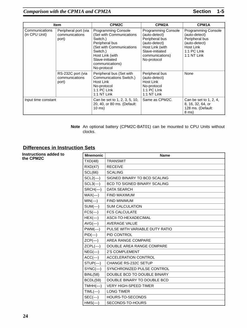
Item CPM1ACPM2ACPM2CCommunications(in CPU Unit)
Peripheral port (viacommunicationsport)
Programming Console(Set with CommunicationsSwitch.)Peripheral bus(Set with CommunicationsSwitch.)Host Link (withSlave-initiatedcommunications)No-protocol
Programming Console(auto-detect)Peripheral bus(auto-detect)Host Link (withSlave-initiatedcommunications)No-protocol
Programming Console(auto-detect)Peripheral bus(auto-detect)Host Link1:1 PC LInk1:1 NT Link
RS-232C port (viacommunicationsport)
Peripheral bus (Set withCommunications Switch.)Host LinkNo-protocol1:1 PC LInk1:1 NT Link
Peripheral bus(auto-detect)Host LinkNo-protocol1:1 PC LInk1:1 NT Link
None
Input time constant Can be set to 1, 2, 3, 5, 10,20, 40, or 80 ms. (Default:10 ms)
Same as CPM2C. Can be set to 1, 2, 4,8, 16, 32, 64, or128 ms. (Default:8 ms)
Note An optional battery (CPM2C-BAT01) can be mounted to CPU Units withoutclocks.
Differences in Instruction SetsMnemonic Name
TXD(48) TRANSMIT
RXD(47) RECEIVE
SCL(66) SCALING
SCL2(––) SIGNED BINARY TO BCD SCALING
SCL3(––) BCD TO SIGNED BINARY SCALING
SRCH(––) DATA SEARCH
MAX(––) FIND MAXIMUM
MIN(––) FIND MINIMUM
SUM(––) SUM CALCULATION
FCS(––) FCS CALCULATE
HEX(––) ASCII-TO-HEXADECIMAL
AVG(––) AVERAGE VALUE
PWM(––) PULSE WITH VARIABLE DUTY RATIO
PID(––) PID CONTROL
ZCP(––) AREA RANGE COMPARE
ZCPL(––) DOUBLE AREA RANGE COMPARE
NEG(––) 2’S COMPLEMENT
ACC(––) ACCELERATION CONTROL
STUP(––) CHANGE RS-232C SETUP
SYNC(––) SYNCHRONIZED PULSE CONTROL
BINL(58) DOUBLE BCD TO DOUBLE BINARY
BCDL(59) DOUBLE BINARY TO DOUBLE BCD
TMHH(––) VERY HIGH-SPEED TIMER
TIML(––) LONG TIMER
SEC(––) HOURS-TO-SECONDS
HMS(––) SECONDS-TO-HOURS
Instructions added tothe CPM2C

!
1-5SectionComparison with the CPM1A and CPM2A
25
Instructions with Changed Specifications
Mnemonic Name CPM2C CPM1A
INI(61) MODE CONTROL Supports the interrupt input (counter mode) PVchange operation.
Supports the pulse output PV change operation.
Supports the pulse synchronization control stopoperation.
Does not support theseoperations.
PRV(62) HIGH-SPEEDCOUNTER PV READ
Supports the interrupt input (counter mode) PV readoperation.
Supports the pulse output PV read operation.
Does not support theseoperations.
CTBL(63) COMPARISON TABLELOAD
The count is compared with all of the target valuesin the target value comparison table.
The count is comparedwith each target value inthe order that theyappear in the targetvalue comparison table.
PULS(65) SET PULSES Supports absolute pulse specification, but thecoordinate system must be set to absolutecoordinates.
Does not supportabsolute pulsespecification.
INT(89) INTERRUPT CONTROL Supports a count-up interrupt for incrementingcounters.
Does not support thisinterrupt function.
Caution Before using a CPM1A program containing one or more of the instructions in thetable above, check the program to be sure that it will operate properly and editthe program if necessary. The CPM2C may not operate properly if a CPM1A pro-gram with these instructions is transferred and executed unchanged.
The following three instructions are allocated function codes that were not usedin the CPM1A.
Instruction CPM2C CPM1A
RXD(47) RECEIVE Not allocated. (NOP(00))
TXD(48) TRANSMIT
SCL(66) SCALING
Differences in I/O Memory
The following table shows differences in the SR area. (PV is the abbreviation forpresent value.)
Function CPM2C CPM1A
Pulse output 0 PV SR 228 to SR 229 Not
Pulse output 1 PV SR 230 to SR 231 supported.
Pulse output 0 PV Reset Bit SR 25204
Pulse output 1 PV Reset Bit SR 25205
RS-232C Port Reset Bit SR 25209
Battery Error Flag SR 25308
Changing RS-232C Port Setup Flag SR 25312
Added Function CodeAllocations
SR Area Differences
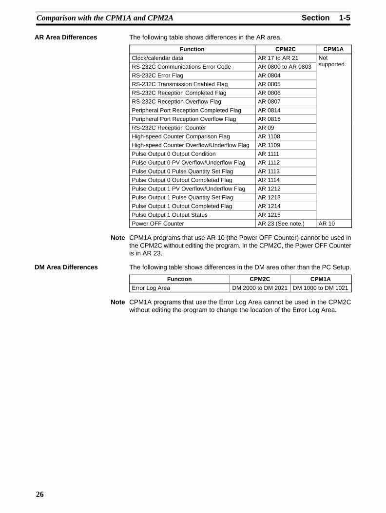
1-5SectionComparison with the CPM1A and CPM2A
26
The following table shows differences in the AR area.
Function CPM2C CPM1A
Clock/calendar data AR 17 to AR 21 Not
RS-232C Communications Error Code AR 0800 to AR 0803 supported.
RS-232C Error Flag AR 0804
RS-232C Transmission Enabled Flag AR 0805
RS-232C Reception Completed Flag AR 0806
RS-232C Reception Overflow Flag AR 0807
Peripheral Port Reception Completed Flag AR 0814
Peripheral Port Reception Overflow Flag AR 0815
RS-232C Reception Counter AR 09
High-speed Counter Comparison Flag AR 1108
High-speed Counter Overflow/Underflow Flag AR 1109
Pulse Output 0 Output Condition AR 1111
Pulse Output 0 PV Overflow/Underflow Flag AR 1112
Pulse Output 0 Pulse Quantity Set Flag AR 1113
Pulse Output 0 Output Completed Flag AR 1114
Pulse Output 1 PV Overflow/Underflow Flag AR 1212
Pulse Output 1 Pulse Quantity Set Flag AR 1213
Pulse Output 1 Output Completed Flag AR 1214
Pulse Output 1 Output Status AR 1215
Power OFF Counter AR 23 (See note.) AR 10
Note CPM1A programs that use AR 10 (the Power OFF Counter) cannot be used inthe CPM2C without editing the program. In the CPM2C, the Power OFF Counteris in AR 23.
The following table shows differences in the DM area other than the PC Setup.
Function CPM2C CPM1A
Error Log Area DM 2000 to DM 2021 DM 1000 to DM 1021
Note CPM1A programs that use the Error Log Area cannot be used in the CPM2Cwithout editing the program to change the location of the Error Log Area.
AR Area Differences
DM Area Differences
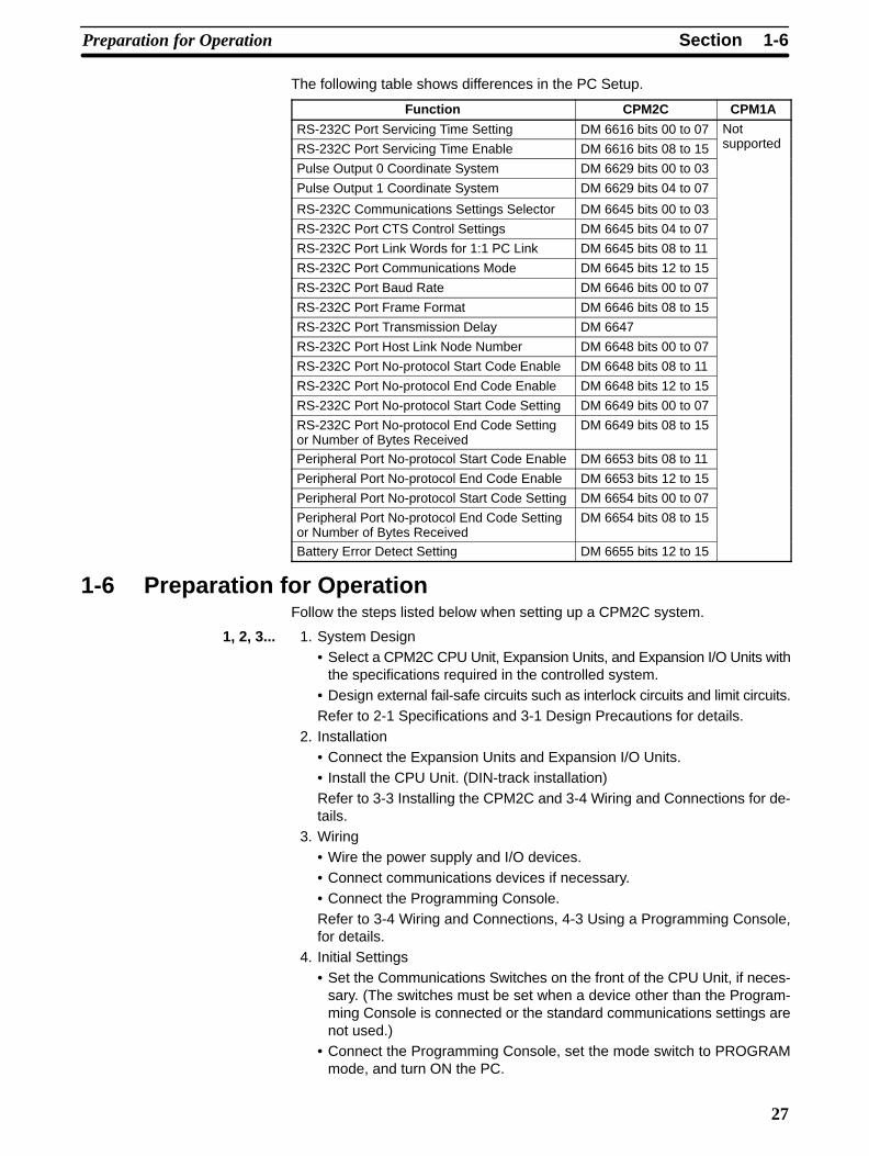
1-6SectionPreparation for Operation
27
The following table shows differences in the PC Setup.
Function CPM2C CPM1A
RS-232C Port Servicing Time Setting DM 6616 bits 00 to 07 Not
RS-232C Port Servicing Time Enable DM 6616 bits 08 to 15 supported
Pulse Output 0 Coordinate System DM 6629 bits 00 to 03
Pulse Output 1 Coordinate System DM 6629 bits 04 to 07
RS-232C Communications Settings Selector DM 6645 bits 00 to 03
RS-232C Port CTS Control Settings DM 6645 bits 04 to 07
RS-232C Port Link Words for 1:1 PC Link DM 6645 bits 08 to 11
RS-232C Port Communications Mode DM 6645 bits 12 to 15
RS-232C Port Baud Rate DM 6646 bits 00 to 07
RS-232C Port Frame Format DM 6646 bits 08 to 15
RS-232C Port Transmission Delay DM 6647
RS-232C Port Host Link Node Number DM 6648 bits 00 to 07
RS-232C Port No-protocol Start Code Enable DM 6648 bits 08 to 11
RS-232C Port No-protocol End Code Enable DM 6648 bits 12 to 15
RS-232C Port No-protocol Start Code Setting DM 6649 bits 00 to 07
RS-232C Port No-protocol End Code Settingor Number of Bytes Received
DM 6649 bits 08 to 15
Peripheral Port No-protocol Start Code Enable DM 6653 bits 08 to 11
Peripheral Port No-protocol End Code Enable DM 6653 bits 12 to 15
Peripheral Port No-protocol Start Code Setting DM 6654 bits 00 to 07
Peripheral Port No-protocol End Code Settingor Number of Bytes Received
DM 6654 bits 08 to 15
Battery Error Detect Setting DM 6655 bits 12 to 15
1-6 Preparation for OperationFollow the steps listed below when setting up a CPM2C system.
1, 2, 3... 1. System Design• Select a CPM2C CPU Unit, Expansion Units, and Expansion I/O Units with
the specifications required in the controlled system.• Design external fail-safe circuits such as interlock circuits and limit circuits.Refer to 2-1 Specifications and 3-1 Design Precautions for details.
2. Installation• Connect the Expansion Units and Expansion I/O Units.• Install the CPU Unit. (DIN-track installation)Refer to 3-3 Installing the CPM2C and 3-4 Wiring and Connections for de-tails.
3. Wiring• Wire the power supply and I/O devices.• Connect communications devices if necessary.• Connect the Programming Console.Refer to 3-4 Wiring and Connections, 4-3 Using a Programming Console,for details.
4. Initial Settings• Set the Communications Switches on the front of the CPU Unit, if neces-
sary. (The switches must be set when a device other than the Program-ming Console is connected or the standard communications settings arenot used.)
• Connect the Programming Console, set the mode switch to PROGRAMmode, and turn ON the PC.
1-6SectionPreparation for Operation
28
• Check the CPU Unit’s LED indicators and the Programming Console’s dis-play.
• Clear the PC’s memory. (All Clear)
• Make PC Setup settings.
Refer to 3-3 Installing the CPM2C and 4-3-4 Preparation for Operation fordetails.
5. Create Ladder Program
• Create a ladder program to control the system.
Refer to Section 4 Using Programming Devices and the ProgrammingManual for details.
6. Write Ladder Program in PC
• Write the ladder program in the PC with the Programming Console ortransfer the program to the PC from the Support Software.
Refer to Section 4 Using Programming Devices, to the SYSMAC SupportSoftware Operation Manuals and to the CPT User Manual for details.
7. Test Run
• Check I/O wiring in PROGRAM mode.
• Check and debug program execution in MONITOR mode.
Refer to Section 5 Test Runs and Error Processing for details.
29
SECTION 2Unit Components and Specifications
This section describes the main components of the Units that go together to create a CPM2C PC and provides the technicalspecifications of the Units.
2-1 Specifications 30. . . . . . . . . . . . . . . . . . . . . . . . . . . . . . . . . . . . . . . . . . . . . . . . . . . . . . . . . . . . 2-1-1 General Specifications 30. . . . . . . . . . . . . . . . . . . . . . . . . . . . . . . . . . . . . . . . . . . . . . 2-1-2 Characteristics 30. . . . . . . . . . . . . . . . . . . . . . . . . . . . . . . . . . . . . . . . . . . . . . . . . . . . 2-1-3 AC Power Supply Unit Specifications 33. . . . . . . . . . . . . . . . . . . . . . . . . . . . . . . . . 2-1-4 I/O Specifications 34. . . . . . . . . . . . . . . . . . . . . . . . . . . . . . . . . . . . . . . . . . . . . . . . .
2-2 Unit Components 40. . . . . . . . . . . . . . . . . . . . . . . . . . . . . . . . . . . . . . . . . . . . . . . . . . . . . . . . . 2-2-1 CPU Unit Components 40. . . . . . . . . . . . . . . . . . . . . . . . . . . . . . . . . . . . . . . . . . . . . 2-2-2 Expansion I/O Units 45. . . . . . . . . . . . . . . . . . . . . . . . . . . . . . . . . . . . . . . . . . . . . . . . 2-2-3 CPM2C-MAD11 Analog I/O Unit 51. . . . . . . . . . . . . . . . . . . . . . . . . . . . . . . . . . . . . 2-2-4 CPM2C-TS001/TS101 Temperature Sensor Units 52. . . . . . . . . . . . . . . . . . . . . . . . 2-2-5 CPM2C-SRT21 CompoBus/S I/O Link Unit 53. . . . . . . . . . . . . . . . . . . . . . . . . . . . . 2-2-6 CPM2C-CIF01 Peripheral/RS-232C Adapter Unit 54. . . . . . . . . . . . . . . . . . . . . . . . 2-2-7 CPM2C-CIF11 RS-422/RS-232C Adapter Unit 55. . . . . . . . . . . . . . . . . . . . . . . . . . 2-2-8 AC Power Supply Unit 58. . . . . . . . . . . . . . . . . . . . . . . . . . . . . . . . . . . . . . . . . . . . .
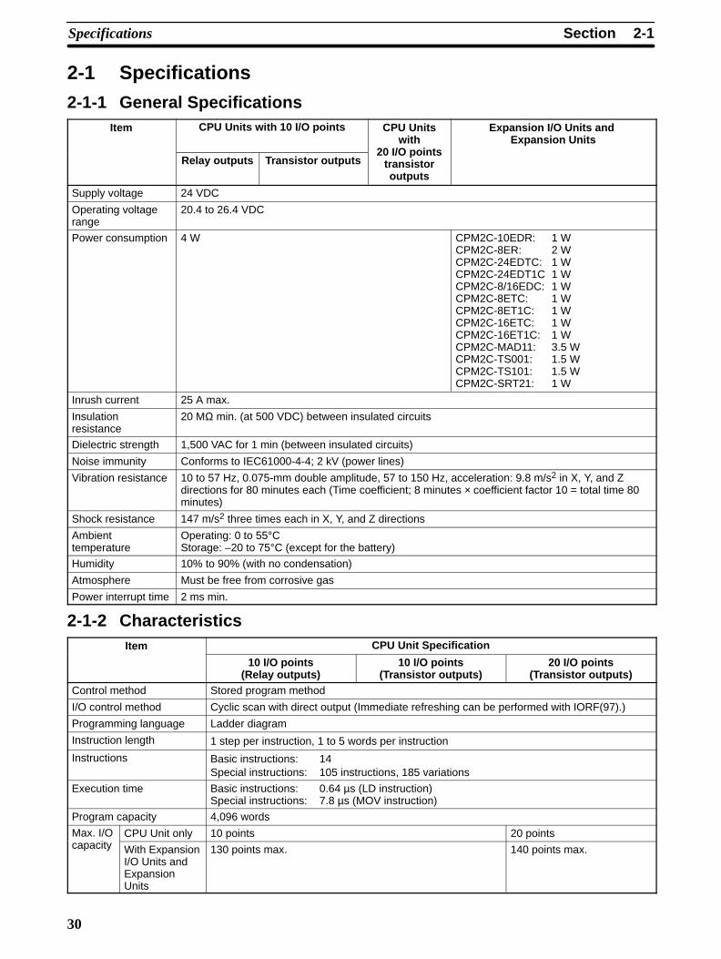
2-1SectionSpecifications
30
2-1 Specifications
2-1-1 General SpecificationsItem CPU Units with 10 I/O points CPU Units
withExpansion I/O Units and
Expansion Units
Relay outputs Transistor outputs20 I/O points
transistoroutputs
Supply voltage 24 VDC
Operating voltagerange
20.4 to 26.4 VDC
Power consumption 4 W CPM2C-10EDR: 1 WCPM2C-8ER: 2 WCPM2C-24EDTC: 1 WCPM2C-24EDT1C 1 WCPM2C-8/16EDC: 1 WCPM2C-8ETC: 1 WCPM2C-8ET1C: 1 WCPM2C-16ETC: 1 WCPM2C-16ET1C: 1 WCPM2C-MAD11: 3.5 WCPM2C-TS001: 1.5 WCPM2C-TS101: 1.5 WCPM2C-SRT21: 1 W
Inrush current 25 A max.
Insulationresistance
20 MΩ min. (at 500 VDC) between insulated circuits
Dielectric strength 1,500 VAC for 1 min (between insulated circuits)
Noise immunity Conforms to IEC61000-4-4; 2 kV (power lines)
Vibration resistance 10 to 57 Hz, 0.075-mm double amplitude, 57 to 150 Hz, acceleration: 9.8 m/s2 in X, Y, and Zdirections for 80 minutes each (Time coefficient; 8 minutes × coefficient factor 10 = total time 80minutes)
Shock resistance 147 m/s2 three times each in X, Y, and Z directions
Ambienttemperature
Operating: 0 to 55°CStorage: –20 to 75°C (except for the battery)
Humidity 10% to 90% (with no condensation)
Atmosphere Must be free from corrosive gas
Power interrupt time 2 ms min.
2-1-2 CharacteristicsItem CPU Unit Specification
10 I/O points(Relay outputs)
10 I/O points(Transistor outputs)
20 I/O points(Transistor outputs)
Control method Stored program method
I/O control method Cyclic scan with direct output (Immediate refreshing can be performed with IORF(97).)
Programming language Ladder diagram
Instruction length 1 step per instruction, 1 to 5 words per instruction
Instructions Basic instructions: 14 Special instructions: 105 instructions, 185 variations
Execution time Basic instructions: 0.64 µs (LD instruction)Special instructions: 7.8 µs (MOV instruction)
Program capacity 4,096 words
Max. I/O CPU Unit only 10 points 20 pointscapacity With Expansion
I/O Units andExpansionUnits
130 points max. 140 points max.
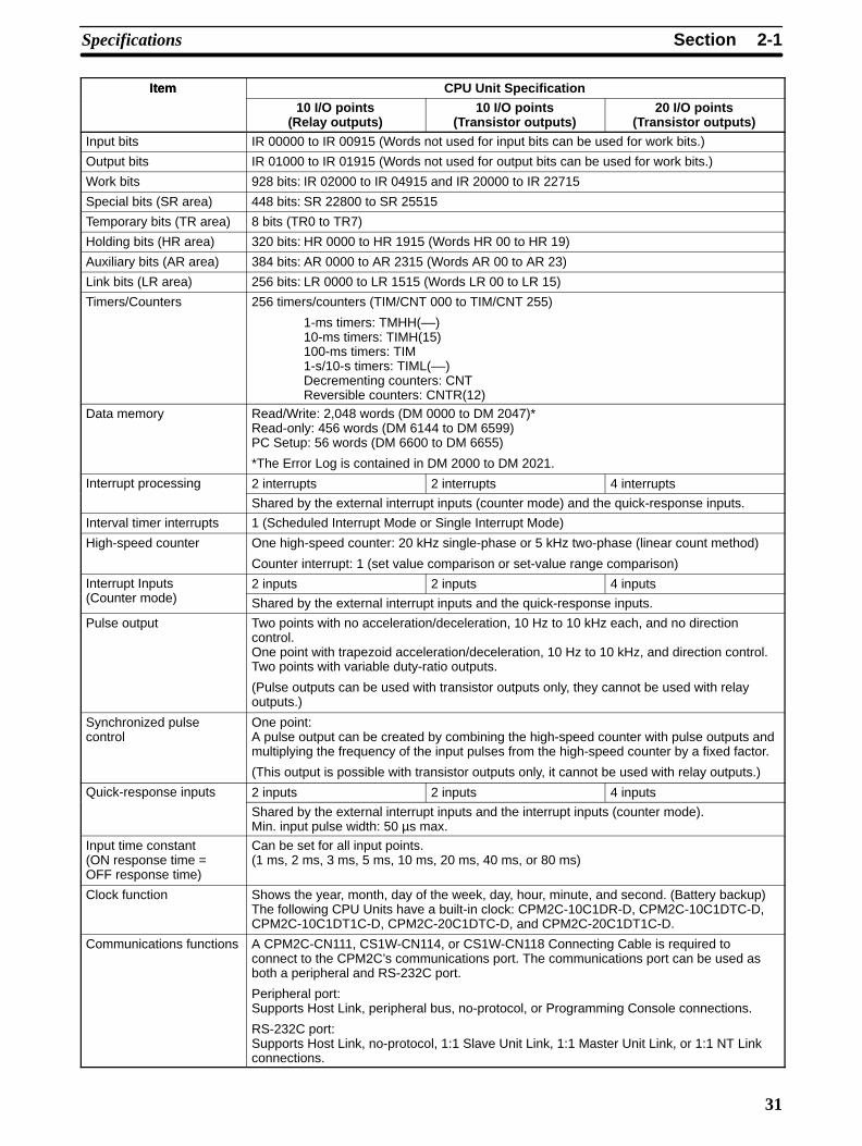
2-1SectionSpecifications
31
Item CPU Unit SpecificationItem
20 I/O points(Transistor outputs)
10 I/O points(Transistor outputs)
10 I/O points(Relay outputs)
Input bits IR 00000 to IR 00915 (Words not used for input bits can be used for work bits.)
Output bits IR 01000 to IR 01915 (Words not used for output bits can be used for work bits.)
Work bits 928 bits: IR 02000 to IR 04915 and IR 20000 to IR 22715
Special bits (SR area) 448 bits: SR 22800 to SR 25515
Temporary bits (TR area) 8 bits (TR0 to TR7)
Holding bits (HR area) 320 bits: HR 0000 to HR 1915 (Words HR 00 to HR 19)
Auxiliary bits (AR area) 384 bits: AR 0000 to AR 2315 (Words AR 00 to AR 23)
Link bits (LR area) 256 bits: LR 0000 to LR 1515 (Words LR 00 to LR 15)
Timers/Counters 256 timers/counters (TIM/CNT 000 to TIM/CNT 255)
1-ms timers: TMHH(––)10-ms timers: TIMH(15)100-ms timers: TIM1-s/10-s timers: TIML(––)Decrementing counters: CNTReversible counters: CNTR(12)
Data memory Read/Write: 2,048 words (DM 0000 to DM 2047)*Read-only: 456 words (DM 6144 to DM 6599)PC Setup: 56 words (DM 6600 to DM 6655)
*The Error Log is contained in DM 2000 to DM 2021.
Interrupt processing 2 interrupts 2 interrupts 4 interrupts
Shared by the external interrupt inputs (counter mode) and the quick-response inputs.
Interval timer interrupts 1 (Scheduled Interrupt Mode or Single Interrupt Mode)
High-speed counter One high-speed counter: 20 kHz single-phase or 5 kHz two-phase (linear count method)
Counter interrupt: 1 (set value comparison or set-value range comparison)
Interrupt Inputs 2 inputs 2 inputs 4 inputs(Counter mode) Shared by the external interrupt inputs and the quick-response inputs.
Pulse output Two points with no acceleration/deceleration, 10 Hz to 10 kHz each, and no directioncontrol.One point with trapezoid acceleration/deceleration, 10 Hz to 10 kHz, and direction control.Two points with variable duty-ratio outputs.
(Pulse outputs can be used with transistor outputs only, they cannot be used with relayoutputs.)
Synchronized pulsecontrol
One point:A pulse output can be created by combining the high-speed counter with pulse outputs andmultiplying the frequency of the input pulses from the high-speed counter by a fixed factor.
(This output is possible with transistor outputs only, it cannot be used with relay outputs.)
Quick-response inputs 2 inputs 2 inputs 4 inputs
Shared by the external interrupt inputs and the interrupt inputs (counter mode).Min. input pulse width: 50 µs max.
Input time constant(ON response time = OFF response time)
Can be set for all input points.(1 ms, 2 ms, 3 ms, 5 ms, 10 ms, 20 ms, 40 ms, or 80 ms)
Clock function Shows the year, month, day of the week, day, hour, minute, and second. (Battery backup)The following CPU Units have a built-in clock: CPM2C-10C1DR-D, CPM2C-10C1DTC-D,CPM2C-10C1DT1C-D, CPM2C-20C1DTC-D, and CPM2C-20C1DT1C-D.
Communications functions A CPM2C-CN111, CS1W-CN114, or CS1W-CN118 Connecting Cable is required toconnect to the CPM2C’s communications port. The communications port can be used asboth a peripheral and RS-232C port.
Peripheral port:Supports Host Link, peripheral bus, no-protocol, or Programming Console connections.
RS-232C port:Supports Host Link, no-protocol, 1:1 Slave Unit Link, 1:1 Master Unit Link, or 1:1 NT Linkconnections.

2-1SectionSpecifications
32
Item CPU Unit SpecificationItem
20 I/O points(Transistor outputs)
10 I/O points(Transistor outputs)
10 I/O points(Relay outputs)
Functions provided byExpansion Units
Analog I/O Unit: Provides 2 analog inputs and 1 analog output.
Temperature Sensor Unit: Provides up to 8 thermocouple or platinum resistancethermometer inputs.
CompoBus/S I/O Link Unit: Provides 8 inputs and 8 outputs as a CompoBus/S Slave.
Memory protection(See notes 1 and 2.)
HR area, AR area, program contents, read/write DM area contents, and counter valuesmaintained during power interruptions.
Memory backup(See notes 1 and 2.)
Flash memory:Program, read-only DM area, and PC Setup
Memory backup:The read/write DM area, HR area, AR area, and counter values are backed up.
CPU Unit with clock (battery): 2-year lifetime at 25°CCPU Unit without clock (capacitor): 10-day backup at 25°CCPU Unit without clock (lithium battery): 5-year lifetime at 25°C
Self-diagnostic functions CPU Unit failure (watchdog timer), I/O bus error, battery error, and memory failure
Program checks No END instruction, programming errors (checked when operation is started)
Note 1. The DM area, HR area, AR area, and counter values are backed up. If thebackup battery or capacitor is discharged, the contents of these areas willbe lost and the data values will revert to the defaults.
2. The contents of the program area, read-only DM area (DM 6144 toDM 6599), and PC Setup (DM 6600 to DM 6655) are stored in flashmemory. The contents of these areas will be read from flash memory thenext time the power is turned ON, even if the backup battery or capacitor isdischarged.
When data has been changed in any of these areas, write the new values toflash memory by switching the CPM2C to MONITOR or RUN mode, or byturning the power OFF and then ON again.
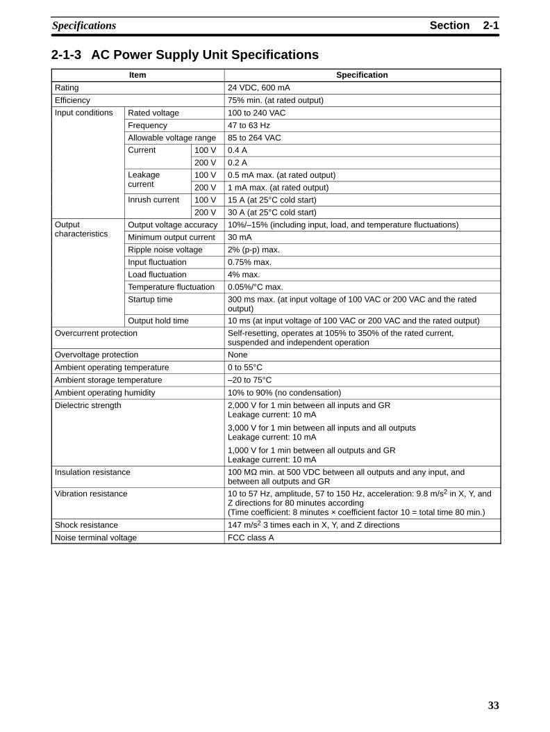
2-1SectionSpecifications
33
2-1-3 AC Power Supply Unit SpecificationsItem Specification
Rating 24 VDC, 600 mA
Efficiency 75% min. (at rated output)
Input conditions Rated voltage 100 to 240 VAC
Frequency 47 to 63 Hz
Allowable voltage range 85 to 264 VAC
Current 100 V 0.4 A
200 V 0.2 A
Leakage 100 V 0.5 mA max. (at rated output)current 200 V 1 mA max. (at rated output)
Inrush current 100 V 15 A (at 25°C cold start)
200 V 30 A (at 25°C cold start)
Output Output voltage accuracy 10%/–15% (including input, load, and temperature fluctuations)characteristics Minimum output current 30 mA
Ripple noise voltage 2% (p-p) max.
Input fluctuation 0.75% max.
Load fluctuation 4% max.
Temperature fluctuation 0.05%/°C max.
Startup time 300 ms max. (at input voltage of 100 VAC or 200 VAC and the ratedoutput)
Output hold time 10 ms (at input voltage of 100 VAC or 200 VAC and the rated output)
Overcurrent protection Self-resetting, operates at 105% to 350% of the rated current,suspended and independent operation
Overvoltage protection None
Ambient operating temperature 0 to 55°CAmbient storage temperature –20 to 75°CAmbient operating humidity 10% to 90% (no condensation)
Dielectric strength 2,000 V for 1 min between all inputs and GRLeakage current: 10 mA
3,000 V for 1 min between all inputs and all outputsLeakage current: 10 mA
1,000 V for 1 min between all outputs and GRLeakage current: 10 mA
Insulation resistance 100 MΩ min. at 500 VDC between all outputs and any input, andbetween all outputs and GR
Vibration resistance 10 to 57 Hz, amplitude, 57 to 150 Hz, acceleration: 9.8 m/s2 in X, Y, andZ directions for 80 minutes according(Time coefficient: 8 minutes × coefficient factor 10 = total time 80 min.)
Shock resistance 147 m/s2 3 times each in X, Y, and Z directions
Noise terminal voltage FCC class A
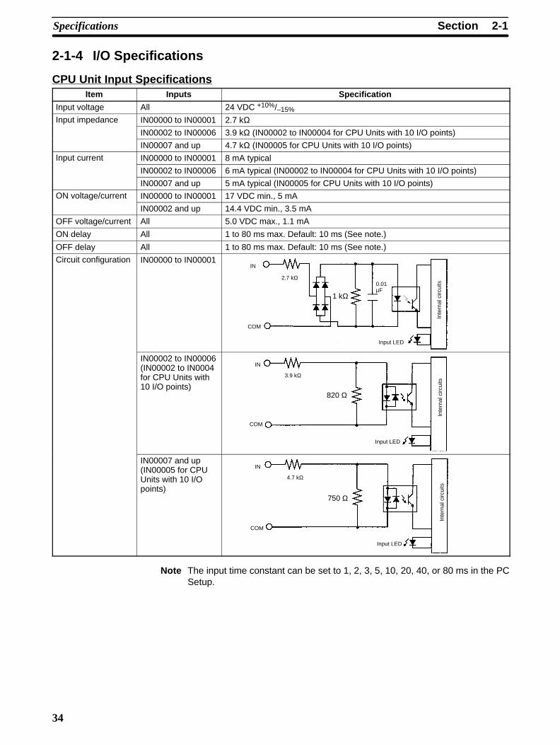
2-1SectionSpecifications
34
2-1-4 I/O Specifications
CPU Unit Input SpecificationsItem Inputs Specification
Input voltage All 24 VDC +10%/–15%
Input impedance IN00000 to IN00001 2.7 kΩIN00002 to IN00006 3.9 kΩ (IN00002 to IN00004 for CPU Units with 10 I/O points)
IN00007 and up 4.7 kΩ (IN00005 for CPU Units with 10 I/O points)
Input current IN00000 to IN00001 8 mA typical
IN00002 to IN00006 6 mA typical (IN00002 to IN00004 for CPU Units with 10 I/O points)
IN00007 and up 5 mA typical (IN00005 for CPU Units with 10 I/O points)
ON voltage/current IN00000 to IN00001 17 VDC min., 5 mA
IN00002 and up 14.4 VDC min., 3.5 mA
OFF voltage/current All 5.0 VDC max., 1.1 mA
ON delay All 1 to 80 ms max. Default: 10 ms (See note.)
OFF delay All 1 to 80 ms max. Default: 10 ms (See note.)
Circuit configuration IN00000 to IN00001
1 kΩ
IN
COM
2.7 kΩ
Input LED
Inte
rnal
circ
uits0.01
µF
IN00002 to IN00006(IN00002 to IN0004for CPU Units with10 I/O points)
820 Ω
IN
COM
3.9 kΩ
Input LEDIn
tern
al c
ircui
ts
IN00007 and up(IN00005 for CPUUnits with 10 I/Opoints)
750 Ω
IN
COM
4.7 kΩ
Input LED
Inte
rnal
circ
uits
Note The input time constant can be set to 1, 2, 3, 5, 10, 20, 40, or 80 ms in the PCSetup.

2-1SectionSpecifications
35
High-speed Counter InputsThe following CPU Unit input bits can be used as high-speed counter inputs. Themaximum count frequency is 5 kHz in differential phase mode and 20 kHz in theother modes.
Input Function
Differential phasemode
Pulse plus directioninput mode
Up/down input mode Increment mode
IN00000 A-phase pulse input Pulse input Increment pulse input Increment pulse input
IN00001 B-phase pulse input Direction input Decrement pulse input Normal input
IN00002 Z-phase pulse input or hardware reset input(IN00002 can be used as a normal input when it is not used as a high-speed counter input.)
The minimum pulse widths for inputs IN00000 (A-phase input) and IN00001 (B-phase input) are as follows:
100 µs min.
T1 T2 T3 T4 : 12.5 µs min.
Phase A
Phase B
50 µs min.
12.5 µsmin.
Pulse plus direction input mode, Up/down inputmode, Increment mode
Differential phase mode
12.5 µsmin. T1 T2 T3 T4
The minimum pulse width for input IN00002 (Z-phase input) is as follows:
50 µs min.
500 µs min.
Phase Z
Interrupt InputsCPM2C PCs are equipped with inputs that can be used as interrupt inputs (inter-rupt input mode or counter mode) and quick-response inputs. The minimumpulse width for these inputs is 50 µs.
In CPU Units with 10 I/O points, inputs IN00003 and IN00004 can be used asinterrupt inputs. In CPU Units with 20 I/O points, inputs IN00003 throughIN00006 can be used as interrupt inputs.

2-1SectionSpecifications
36
Expansion I/O Unit Input SpecificationsItem Specification
Input voltage 24 VDC +10%/–15%
Input impedance 4.7 kΩInput current 5 mA typical
ON voltage/current 14.4 VDC min., 3.5 mA
OFF voltage/current 5.0 VDC max., 1.1 mA
ON delay 1 to 80 ms max. Default: 10 ms (See note.)
OFF delay 1 to 80 ms max. Default: 10 ms (See note.)
Circuit configuration
750 Ω
IN
COM
4.7 kΩ
Input LED
Inte
rnal
circ
uits
Note The input time constant can be set to 1, 2, 3, 5, 10, 20, 40, or 80 ms in the PCSetup.
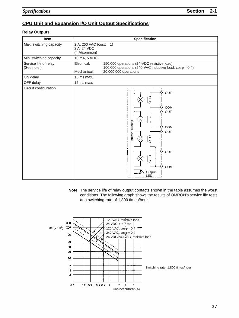
2-1SectionSpecifications
37
CPU Unit and Expansion I/O Unit Output Specifications
Relay Outputs
Item Specification
Max. switching capacity 2 A, 250 VAC (cosφ = 1)2 A, 24 VDC (4 A/common)
Min. switching capacity 10 mA, 5 VDC
Service life of relay(See note.)
Electrical: 150,000 operations (24-VDC resistive load)100,000 operations (240-VAC inductive load, cosφ = 0.4)
Mechanical: 20,000,000 operations
ON delay 15 ms max.
OFF delay 15 ms max.
Circuit configuration
Output LED
Inte
rnal
circ
uits
OUT
OUT
OUT
OUT
COM
COM
COM
Note The service life of relay output contacts shown in the table assumes the worstconditions. The following graph shows the results of OMRON’s service life testsat a switching rate of 1,800 times/hour.
Life (x 104)
Contact current (A)
120 VAC, resistive load
24 VDC/240 VAC, resistive load
Switching rate: 1,800 times/hour
24 VDC, τ = 7 ms120 VAC, cosφ = 0.4240 VAC, cosφ = 0.4
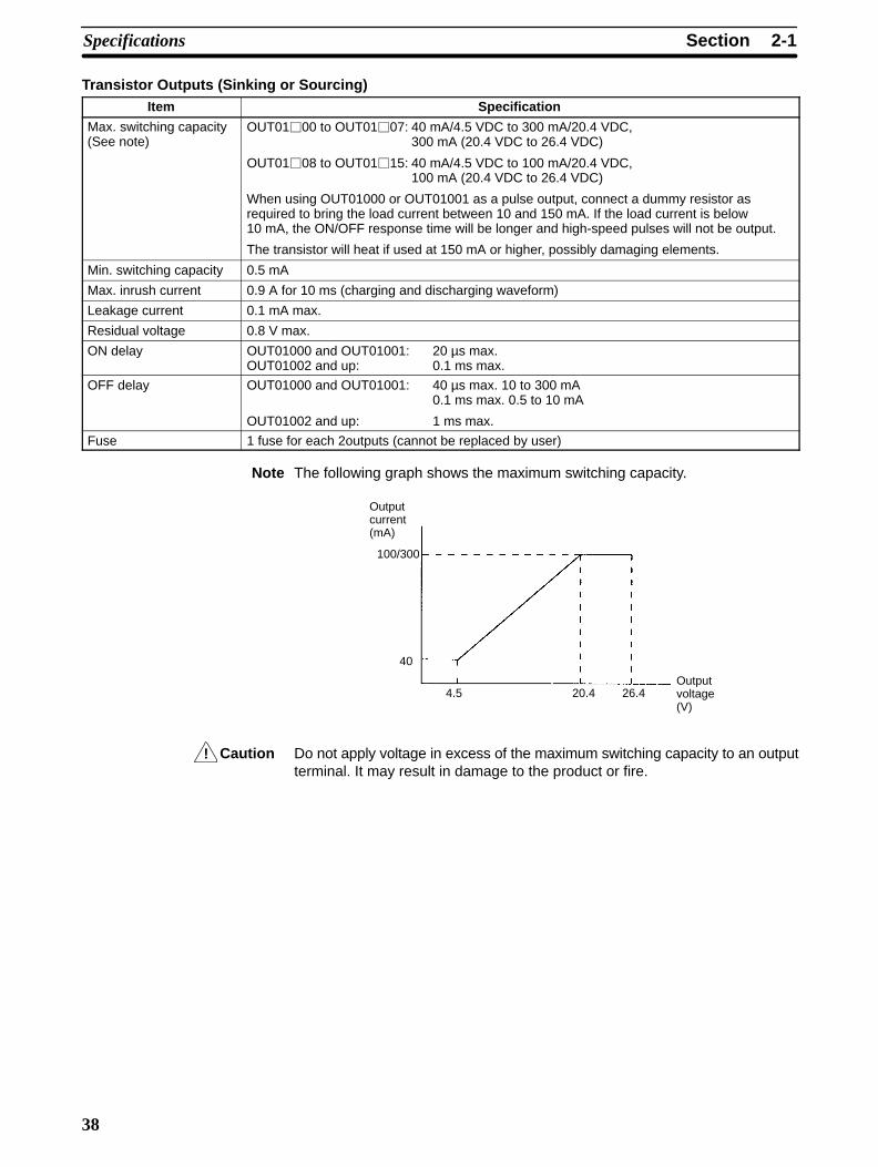
!
2-1SectionSpecifications
38
Transistor Outputs (Sinking or Sourcing)Item Specification
Max. switching capacity(See note)
OUT0100 to OUT0107: 40 mA/4.5 VDC to 300 mA/20.4 VDC,300 mA (20.4 VDC to 26.4 VDC)
OUT0108 to OUT0115: 40 mA/4.5 VDC to 100 mA/20.4 VDC,100 mA (20.4 VDC to 26.4 VDC)
When using OUT01000 or OUT01001 as a pulse output, connect a dummy resistor asrequired to bring the load current between 10 and 150 mA. If the load current is below10 mA, the ON/OFF response time will be longer and high-speed pulses will not be output.
The transistor will heat if used at 150 mA or higher, possibly damaging elements.
Min. switching capacity 0.5 mA
Max. inrush current 0.9 A for 10 ms (charging and discharging waveform)
Leakage current 0.1 mA max.
Residual voltage 0.8 V max.
ON delay OUT01000 and OUT01001: 20 µs max.OUT01002 and up: 0.1 ms max.
OFF delay OUT01000 and OUT01001: 40 µs max. 10 to 300 mA0.1 ms max. 0.5 to 10 mA
OUT01002 and up: 1 ms max.
Fuse 1 fuse for each 2outputs (cannot be replaced by user)
Note The following graph shows the maximum switching capacity.
Outputcurrent(mA)
Outputvoltage(V)
100/300
40
4.5 20.4 26.4
Caution Do not apply voltage in excess of the maximum switching capacity to an outputterminal. It may result in damage to the product or fire.
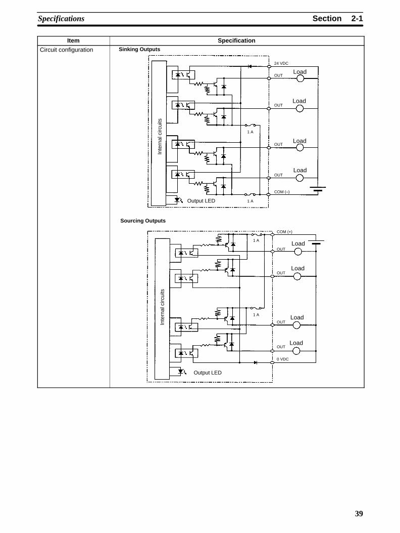
2-1SectionSpecifications
39
Item Specification
Circuit configuration Sinking Outputs
COM (–)
Sourcing Outputs
Output LED
OUT
OUT
24 VDC
OUT
OUT
0 VDC
Output LED
OUT
OUT
COM (+)
OUT
OUT
1 A
1 A
1 A
Inte
rnal
circ
uits
Inte
rnal
circ
uits
1 A
Load
Load
Load
Load
Load
Load
Load
Load

2-2SectionUnit Components
40
2-2 Unit Components
2-2-1 CPU Unit Components
CPU Unit Component Names
2. Input terminals
7. Communications port
8. Communications switches
5. Input indicators
6. Output indicators
3. Output terminals
4. PC status indicators
Front View: CPU Unit with Relay Outputs
2. Input connector
7. Communications port
8. Communications switches
5. Input indicators
6. Output indicators
3. Output connector
4. PC status indicators
Front View: CPU Unit with Transistor Outputs
10. Low battery detection switch
9. BatteryTop View Bottom View
1. Power supplyconnector
11. Expansion I/O con-nector (output con-nector)
Right Side:CPU Unit with Relay Outputs
Right Side:CPU Unit with Transistor Outputs
11. Expansion I/O connector(output connector)
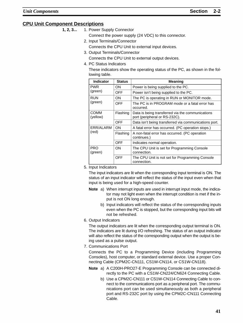
2-2SectionUnit Components
41
CPU Unit Component Descriptions1, 2, 3... 1. Power Supply Connector
Connect the power supply (24 VDC) to this connector.2. Input Terminals/Connector
Connects the CPU Unit to external input devices.3. Output Terminals/Connector
Connects the CPU Unit to external output devices.4. PC Status Indicators
These indicators show the operating status of the PC, as shown in the fol-lowing table.
Indicator Status MeaningPWR ON Power is being supplied to the PC.(green) OFF Power isn’t being supplied to the PC.
RUN ON The PC is operating in RUN or MONITOR mode.(green) OFF The PC is in PROGRAM mode or a fatal error has
occurred.COMM(yellow)
Flashing Data is being transferred via the communicationsport (peripheral or RS-232C).
OFF Data isn’t being transferred via communications port.
ERR/ALARM ON A fatal error has occurred. (PC operation stops.)(red) Flashing A non-fatal error has occurred. (PC operation
continues.)
OFF Indicates normal operation.
PRO(green)
ON The CPU Unit is set for Programming Consoleconnection.
OFF The CPU Unit is not set for Programming Consoleconnection.
5. Input IndicatorsThe input indicators are lit when the corresponding input terminal is ON. Thestatus of an input indicator will reflect the status of the input even when thatinput is being used for a high-speed counter.
Note a) When interrupt inputs are used in interrupt input mode, the indica-tor may not light even when the interrupt condition is met if the in-put is not ON long enough.
b) Input indicators will reflect the status of the corresponding inputseven when the PC is stopped, but the corresponding input bits willnot be refreshed.
6. Output IndicatorsThe output indicators are lit when the corresponding output terminal is ON.The indicators are lit during I/O refreshing. The status of an output indicatorwill also reflect the status of the corresponding output when the output is be-ing used as a pulse output.
7. Communications PortConnects the PC to a Programming Device (including ProgrammingConsoles), host computer, or standard external device. Use a proper Con-necting Cable (CPM2C-CN111, CS1W-CN114, or CS1W-CN118).
Note a) A C200H-PRO27-E Programming Console can be connected di-rectly to the PC with a CS1W-CN224/CN624 Connecting Cable.
b) Use a CPM2C-CN111 or CS1W-CN114 Connecting Cable to con-nect to the communications port as a peripheral port. The commu-nications port can be used simultaneously as both a peripheralport and RS-232C port by using the CPM2C-CN111 ConnectingCable.

2-2SectionUnit Components
42
c) Use a CPM2C-CN111 or CS1W-CN118 Connecting Cable to con-nect to the communications port as a RS-232C port. The commu-nications port can be used simultaneously as both a peripheralport and RS-232C port by using the CPM2C-CN111 ConnectingCable
8. Communications Switches
The Communications Switches control the communications settings for thecommunications port (peripheral port and RS-232C port). (The standardsettings are 1 start bit, 7 data bits, 2 stop bits, even parity, and 9,600 bpsbaud rate.)
Switchsettings
Peripheral port communications RS-232C portcommunications
SW1 SW2
OFF OFF Programming Console connection The settings in the PC
OFF ON Other Programming Device:The settings in the PC Setup(DM 6650 to DM 6654) are used.
Setup (DM 6645 toDM 6649) are used.
ON OFF Programming Console connection The standard settings are
ON ON Other Programming Device:The standard settings are used.
used.
Be sure that Communications Switch 2 is OFF when connecting a ProgrammingConsole. The green PRO indicator on the front of the CPU Unit will be lit.
9. Battery
This battery backs up memory in CPU Units with an internal clock. The bat-tery is connected when the Unit is shipped.
Note A battery is not included in CPU Units without an internal clock, but aCPM2C-BAT01 Battery can be purchased separately and connectedto backup memory.
10. Low Battery Detection Switch
This switch enables or disables the detection of a low-battery error. When abattery is not connected, disable low-battery detection by sliding the switchback (toward the battery).
Switch position Low-battery detection
Forward (away from battery) Error detection enabled
Back (toward battery) Error detection disabled
11. Expansion I/O Connector
Connects the PC’s CPU Unit to an Expansion I/O Unit or Expansion Unit. Upto 5 Expansion I/O Units and Expansion Units can be connected to a CPUUnit. A cover for the expansion I/O connector is included with the CPU Unit.
Disabled
Enabled

2-2SectionUnit Components
43
I/O Terminal and Connector Pin AllocationCPU Unit with 10 I/O Points and Relay Outputs
Inputs Outputs
Shared common
CPU Unit with 10 I/O Points and Transistor Outputs
Inputs Outputs
Sinking Sourcing

2-2SectionUnit Components
44
CPU Unit with 20 I/O Points
Inputs Outputs
Sinking Sourcing
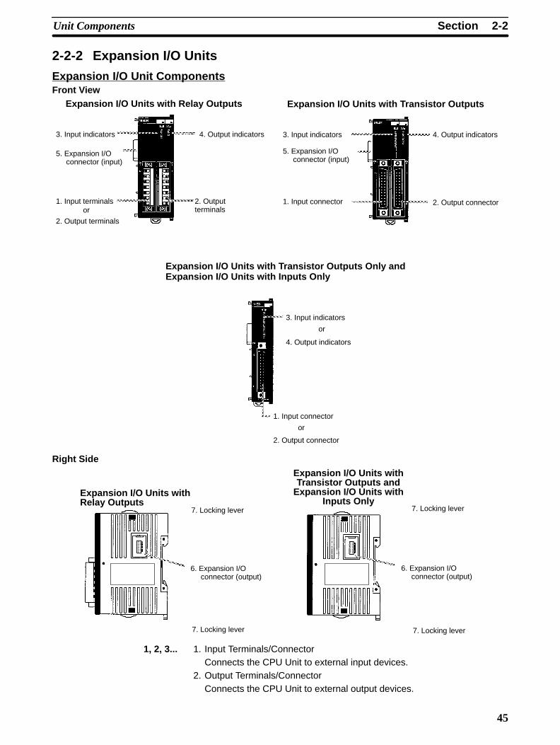
2-2SectionUnit Components
45
2-2-2 Expansion I/O Units
Expansion I/O Unit ComponentsFront View
1. Input terminals
3. Input indicators 4. Output indicators
2. Outputterminals
Expansion I/O Units with Relay Outputs
5. Expansion I/Oconnector (input)
or
2. Output terminals
1. Input connector
3. Input indicators 4. Output indicators
2. Output connector
Expansion I/O Units with Transistor Outputs
5. Expansion I/Oconnector (input)
Expansion I/O Units with Transistor Outputs Only andExpansion I/O Units with Inputs Only
3. Input indicators
or
4. Output indicators
1. Input connector
2. Output connector
or
Right Side
Expansion I/O Units withRelay Outputs
6. Expansion I/Oconnector (output)
7. Locking lever
7. Locking lever
Expansion I/O Units withTransistor Outputs and
Expansion I/O Units withInputs Only
6. Expansion I/Oconnector (output)
7. Locking lever
7. Locking lever
1, 2, 3... 1. Input Terminals/ConnectorConnects the CPU Unit to external input devices.
2. Output Terminals/ConnectorConnects the CPU Unit to external output devices.
2-2SectionUnit Components
46
3. Input Indicators
The input indicators are lit when the corresponding input terminal is ON.
Note Input indicators will reflect the status of the corresponding inputseven when the PC is stopped, but the corresponding input bits will notbe refreshed.
4. Output Indicators
The output indicators are lit when the corresponding output terminal is ON.
5. Expansion I/O Connector (Input)
Connects the Expansion I/O Unit to the CPU Unit or the previous ExpansionUnit or Expansion I/O Unit.
Note The indicators are lit during I/O refreshing. The status of an output in-dicator will also reflect the status of the corresponding output whenthe output is being used as a pulse output.
6. Expansion I/O Connector (Output)
Connects the Expansion I/O Unit to the next Expansion I/O Unit or Expan-sion Unit, if necessary. Up to 5 Expansion I/O Units and Expansion Units canbe connected to a CPU Unit. Only 10 words, however, can be allocated forinput and output.
A cover for the expansion I/O connector is not included with the ExpansionI/O Unit. Use the cover included with the CPU Unit to cover the unusedexpansion I/O connector on the last Expansion I/O Unit or Expansion Unit inthe PC.
7. Locking Lever
Used for securing Expansion I/O Units.

2-2SectionUnit Components
47
I/O Terminal and Connector Pin Allocation
CPM2C-10EDR Expansion I/O UnitRelay Outputs, 10 I/O Points
Inputs Outputs
Shared common
COM
IN 5
IN 4
IN 3
IN 2
IN 1
IN 0
7
6
5
4
3
21
1
2
3
4
5
6
7 COM
IN 5
OUT 3
OUT 2
OUT 1
OUT 0
COM
COM
CPM2C-8ER Expansion I/O UnitRelay Outputs, 8 Output Points
Outputs Outputs
Shared common
Shared common
COM
OUT 3
OUT 2
COM
OUT 1
COM
OUT 0
OUT 4
COM
OUT 5
COM
OUT 6
OUT 7
COM
1
2
3
4
5
6
71
2
3
4
5
6
7

2-2SectionUnit Components
48
CPM2C-24EDTC/24EDT1C Expansion I/O UnitTransistor Outputs, 24 I/O Points
Inputs Outputs
Sinking Sourcing

2-2SectionUnit Components
49
CPM2C-8EDC Expansion I/O UnitDC Inputs, 8 Input Points
Inputs
NC
NC
NC
NC
NC
NC
NC
NC
NC
NC
NC
NC
NC
NC
NC
COM
IN 7
IN 6
IN 5
IN 4
IN 3
IN 2
IN 1
IN 0
B A
1
2
3
4
5
6
7
8
9
10
11
12
1
2
3
4
5
6
7
8
9
10
11
12
CPM2C-16EDC Expansion I/O UnitDC Inputs, 16 Input Points
Inputs
NC
NC
NC
NC
NC
NC
COM
IN 7
IN 6
IN 5
IN 4
IN 3
IN 2
IN 1
IN 0
B A
1
2
3
4
5
6
7
8
9
10
11
12
1
2
3
4
5
6
7
8
9
10
11
12
COM
IN 15
IN 14
IN 13
IN 12
IN 11
IN 10
IN 9
IN 8

2-2SectionUnit Components
50
CPM2C-8ETC/8ET1C Expansion I/O UnitsTransistor Outputs, 8 Output Points
Outputs
COM (–)
A
1
2
3
4
5
6
7
8
9
10
11
12
B
1
2
3
4
5
6
7
8
9
10
11
12
A
1
2
3
4
5
6
7
8
9
10
11
12
B
1
2
3
4
5
6
7
8
9
10
11
12
NC
NC
NC
NC
NC
NC
NC
NC
NC
NC
NC
NCNC
NC
0 V
COM (+24 V)
OUT 7
OUT 6
OUT 5
OUT 4
OUT 3
OUT 2
OUT 1
OUT 0NC
NC
NC
NC
NC
NC
NC
NC
NC
NC
NC
NCNC
NC
0 V
OUT 7
OUT 6
OUT 5
OUT 4
OUT 3
OUT 2
OUT 1
OUT 0
CPM2C-16ETC/16ET1C Expansion I/O UnitTransistor Outputs, 16 Output Points
Outputs
Sinking Sourcing
COM (–)
A
1
2
3
4
5
6
7
8
9
10
11
12
B
1
2
3
4
5
6
7
8
9
10
11
12
A
1
2
3
4
5
6
7
8
9
10
11
12
B
1
2
3
4
5
6
7
8
9
10
11
12NC
NC
0 V
COM (+24 V)
OUT 7
OUT 6
OUT 5
OUT 4
OUT 3
OUT 2
OUT 1
OUT 0
NC
NCNC
NC
24 V
OUT 7
OUT 6
OUT 5
OUT 4
OUT 3
OUT 2
OUT 1
OUT 0
24 V
COM (–)
OUT 15
OUT 14
OUT 13
OUT 12
OUT 11
OUT 10
OUT 9
OUT 8
NC
NC
OUT 15
OUT 14
OUT 13
OUT 12
OUT 11
OUT 10
OUT 9
OUT 8
COM (+24 V)
0 V
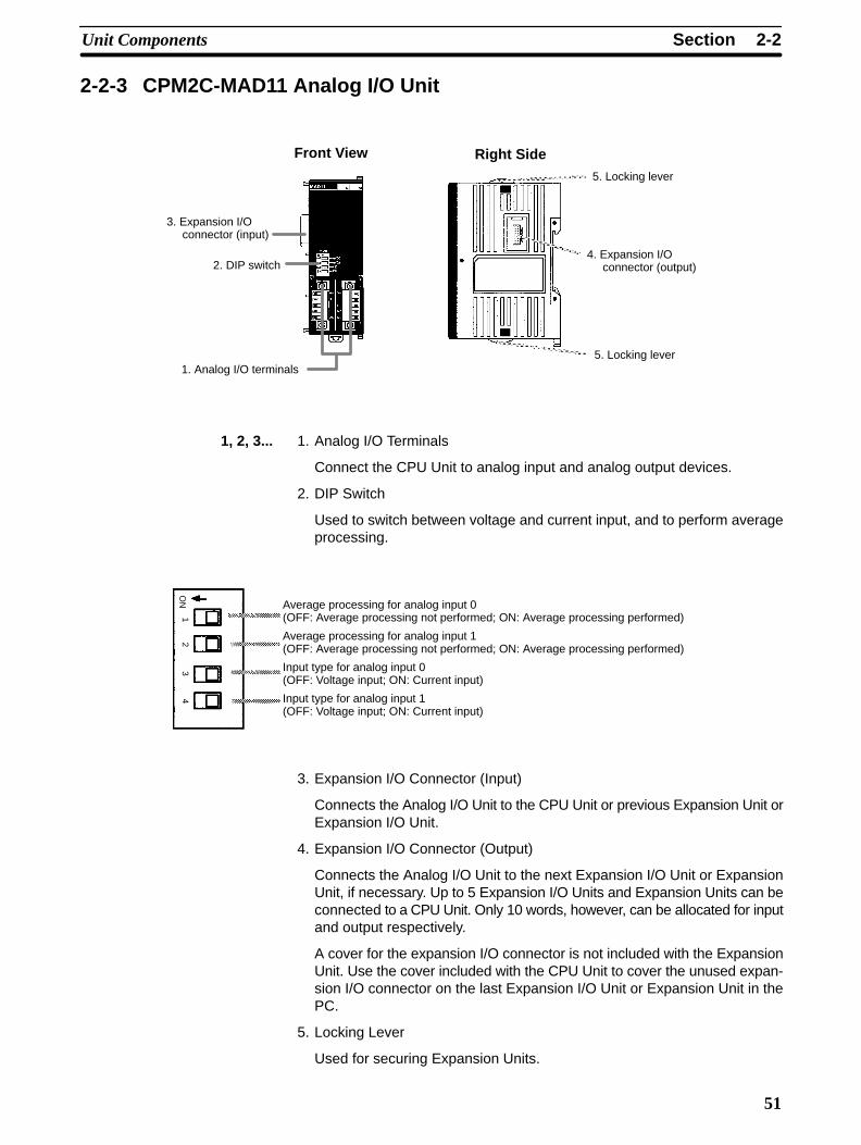
2-2SectionUnit Components
51
2-2-3 CPM2C-MAD11 Analog I/O Unit
Front View Right Side
3. Expansion I/Oconnector (input)
2. DIP switch
1. Analog I/O terminals
5. Locking lever
4. Expansion I/Oconnector (output)
5. Locking lever
1, 2, 3... 1. Analog I/O Terminals
Connect the CPU Unit to analog input and analog output devices.
2. DIP Switch
Used to switch between voltage and current input, and to perform averageprocessing.
Average processing for analog input 0(OFF: Average processing not performed; ON: Average processing performed)
Average processing for analog input 1(OFF: Average processing not performed; ON: Average processing performed)
Input type for analog input 0(OFF: Voltage input; ON: Current input)
Input type for analog input 1(OFF: Voltage input; ON: Current input)
ON
12
34
3. Expansion I/O Connector (Input)
Connects the Analog I/O Unit to the CPU Unit or previous Expansion Unit orExpansion I/O Unit.
4. Expansion I/O Connector (Output)
Connects the Analog I/O Unit to the next Expansion I/O Unit or ExpansionUnit, if necessary. Up to 5 Expansion I/O Units and Expansion Units can beconnected to a CPU Unit. Only 10 words, however, can be allocated for inputand output respectively.
A cover for the expansion I/O connector is not included with the ExpansionUnit. Use the cover included with the CPU Unit to cover the unused expan-sion I/O connector on the last Expansion I/O Unit or Expansion Unit in thePC.
5. Locking Lever
Used for securing Expansion Units.
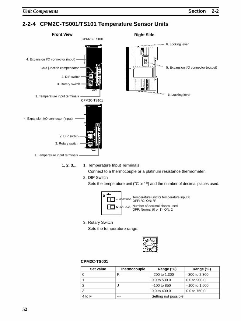
2-2SectionUnit Components
52
2-2-4 CPM2C-TS001/TS101 Temperature Sensor Units
Front View Right Side
1. Temperature input terminals
3. Rotary switch
2. DIP switch
Cold junction compensator
4. Expansion I/O connector (input)
CPM2C-TS001
1. Temperature input terminals
3. Rotary switch
2. DIP switch
4. Expansion I/O connector (input)
CPM2C-TS101
6. Locking lever
6. Locking lever
5. Expansion I/O connector (output)
1, 2, 3... 1. Temperature Input Terminals
Connect to a thermocouple or a platinum resistance thermometer.
2. DIP Switch
Sets the temperature unit (°C or °F) and the number of decimal places used.
Temperature unit for temperature input 0OFF: °C; ON: °FNumber of decimal places usedOFF: Normal (0 or 1); ON: 2
3. Rotary Switch
Sets the temperature range.
CPM2C-TS001
Set value Thermocouple Range (°C) Range (°F)
0 K –200 to 1,300 –300 to 2,300
1 0.0 to 500.0 0.0 to 900.0
2 J –100 to 850 –100 to 1,500
3 0.0 to 400.0 0.0 to 750.0
4 to F --- Setting not possible
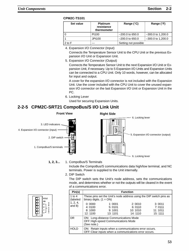
2-2SectionUnit Components
53
CPM2C-TS101
Set value Platinumresistance
thermometer
Range (°C) Range (°F)
0 Pt100 –200.0 to 650.0 –300.0 to 1,200.0
1 JPt100 –200.0 to 650.0 –300.0 to 1,200.0
2 to F --- Setting not possible
4. Expansion I/O Connector (Input)Connects the Temperature Sensor Unit to the CPU Unit or the previous Ex-pansion I/O Unit or Expansion Unit.
5. Expansion I/O Connector (Output)Connects the Temperature Sensor Unit to the next Expansion I/O Unit or Ex-pansion Unit, if necessary. Up to 5 Expansion I/O Units and Expansion Unitscan be connected to a CPU Unit. Only 10 words, however, can be allocatedfor input and output.A cover for the expansion I/O connector is not included with the ExpansionUnit. Use the cover included with the CPU Unit to cover the unused expan-sion I/O connector on the last Expansion I/O Unit or Expansion Unit in thePC.
6. Locking LeverUsed for securing Expansion Units.
2-2-5 CPM2C-SRT21 CompoBus/S I/O Link UnitFront View Right Side
1. CompoBus/S terminals
2. DIP switch
4. Expansion I/O connector (input)
3. LED indicators
6. Locking lever
6. Locking lever
5. Expansion I/O connector (output)
1, 2, 3... 1. CompoBus/S TerminalsInclude the CompoBus/S communications data high/low terminal, and NCterminals. Power is supplied to the Unit internally.
2. DIP SwitchThe DIP switch sets the Unit’s node address, sets the communicationsmode, and determines whether or not the outputs will be cleared in the eventof a communications error.
Pin(s) Function
1 to 4(labeled1, 2, 4,and 8)
These pins set the Unit’s node address using the DIP switch pins asbinary digits. (1 = ON)
0: 0000 1: 0001 2: 0010 3: 00114: 0100 5: 0101 6: 0110 7: 01118: 1000 9: 1001 10: 1010 11: 1011
12: 1100 13: 1101 14: 1110 15: 1111
DR ON: Long-distance Communications ModeOFF:High-speed Communications Mode(See note.)
HOLD ON: Retain inputs when a communications error occurs.OFF:Clear inputs when a communications error occurs.

2-2SectionUnit Components
54
Note The Long-distance Communications Mode can be used only when connected toone of the following Master Units: C200HW-SRM21-V1, CQM1-SRM21-V1, orSRM1-C0-V2.
3. LED Indicators
These indicators show the status of CompoBus/S communications.
Indicator Status MeaningCOMM ON Communications in progress.(yellow) OFF Communications error or stopped.
ERR ON A communications error has occurred.(red) OFF Indicates normal or no communications.
4. Expansion I/O Connector (Input)
Connects the CompoBus/S I/O Link Unit to the CPU Unit or the previous Ex-pansion I/O Unit or Expansion Unit.
5. Expansion I/O Connector (Output)
Connects the CompoBus/S I/O Link Unit to the next Expansion I/O Unit orExpansion Unit, if necessary. Up to 5 Expansion I/O Units and ExpansionUnits can be connected to a CPU Unit. Only 10 words, however, can be allo-cated for input and output respectively.
A cover for the expansion I/O connector is not included with the ExpansionUnit. Use the cover included with the CPU Unit to cover the unused expan-sion I/O connector on the last Expansion I/O Unit or Expansion Unit in thePC.
6. Locking Lever
Used for securing Expansion Units.
2-2-6 CPM2C-CIF01 Peripheral/RS-232C Adapter Unit
Front View
1. Peripheral port
2. RS-232C port
3. Connector
Do not use the CPM2C-CIF01 with any PC other than the CPM2C.Do not connect another CPM2C-CIF01 or the CPM2C-CIF11 to theCPM2C-CIF01. The CPM2C-CN111 can be connected to theCPM2C-CIF01, but the peripheral port and the RS-232C port of theCPM2C-CN111 cannot be used simultaneously. If an attempt to usethese ports simultaneously is made, communications will not beperformed properly, and this may result in malfunction of equipment.
1, 2, 3... 1. Peripheral Port
Used to connect to Programming Devices (including ProgrammingConsoles), host computers, or general-purpose external devices. Use aspecial connecting cable (CS1W-CN114, CS1W-CN118) for connections.
Note a) The C200H-PRO27 Programming Console can be connecteddirectly to the CPM2C’s CPU Unit using a special connectingcable (CS1W-CN224/624).
b) Use the CS1W-CN114 when using the port as a peripheral port.
c) Use the CS1W-CN118 when using the port as a RS-232C port.
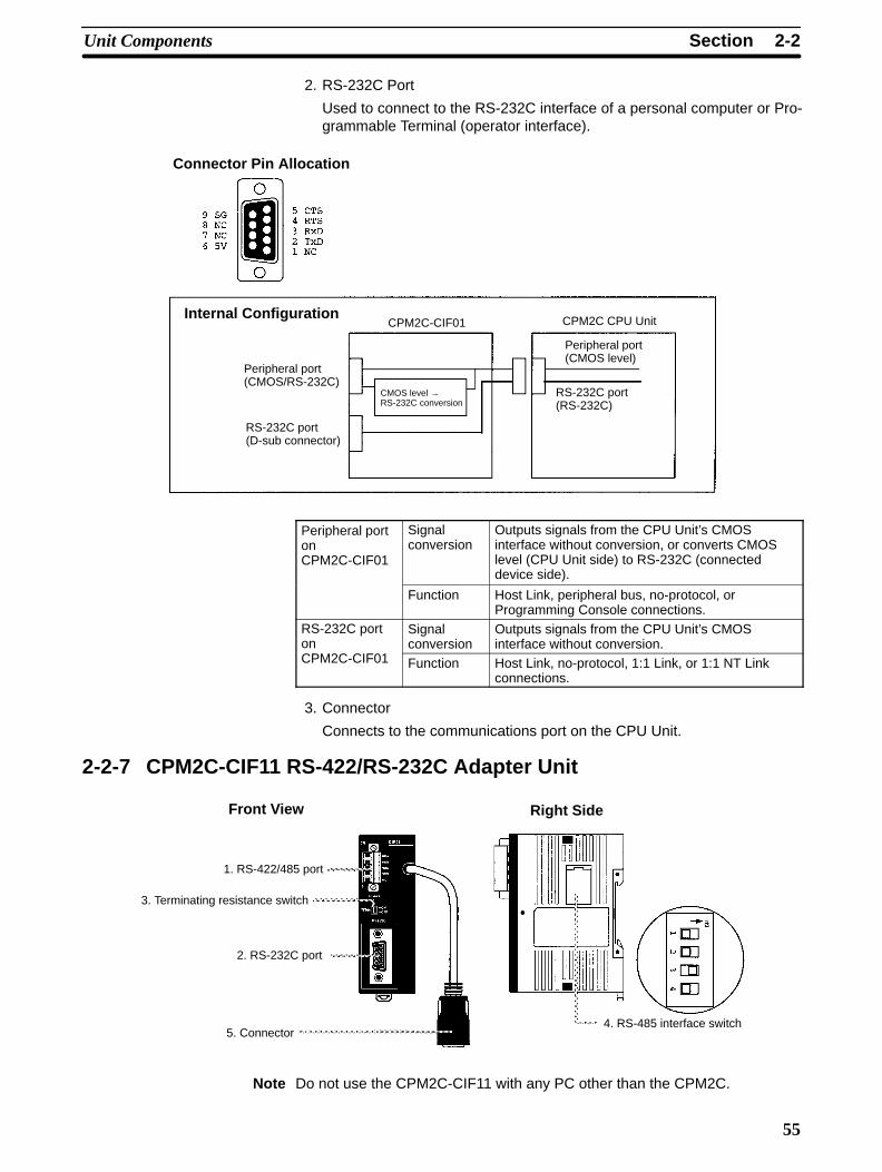
2-2SectionUnit Components
55
2. RS-232C Port
Used to connect to the RS-232C interface of a personal computer or Pro-grammable Terminal (operator interface).
Connector Pin Allocation
Internal ConfigurationCPM2C-CIF01 CPM2C CPU Unit
Peripheral port(CMOS/RS-232C)
RS-232C port(D-sub connector)
CMOS level → RS-232C conversion
Peripheral port(CMOS level)
RS-232C port(RS-232C)
Peripheral portonCPM2C-CIF01
Signalconversion
Outputs signals from the CPU Unit’s CMOSinterface without conversion, or converts CMOSlevel (CPU Unit side) to RS-232C (connecteddevice side).
Function Host Link, peripheral bus, no-protocol, orProgramming Console connections.
RS-232C porton
Signalconversion
Outputs signals from the CPU Unit’s CMOSinterface without conversion.
CPM2C-CIF01 Function Host Link, no-protocol, 1:1 Link, or 1:1 NT Linkconnections.
3. Connector
Connects to the communications port on the CPU Unit.
2-2-7 CPM2C-CIF11 RS-422/RS-232C Adapter Unit
Front View Right Side
1. RS-422/485 port
3. Terminating resistance switch
2. RS-232C port
5. Connector4. RS-485 interface switch
Note Do not use the CPM2C-CIF11 with any PC other than the CPM2C.

2-2SectionUnit Components
56
1, 2, 3... 1. RS422/485 Port
Used to connect to host computers, or standard external devices.
Terminal Arrangement
Receive data (input)
Send data (output)
RDA–
RDB+
SDA–
SDB+
NC
Note The maximum line length is 500 m.
2. RS-232C Port
Used to connect to the RS-232C interface of a personal computer or Pro-grammable Terminal (operator interface).
Connector Pin Arrangement
RS-422/485 Connection ExampleCPM2C-CIF11 B500-AL004
ShieldConnector hood
Internal ConfigurationCPM2C-CIF11 CPM2C CPU Unit
RS-422/485 port(terminal block)
RS-232C port(D-sub connector)
CMOS level → RS-422 conversion
Peripheral port(CMOS level)
RS-232C port(RS-232C)
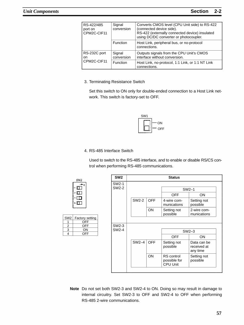
2-2SectionUnit Components
57
RS-422/485port onCPM2C-CIF11
Signalconversion
Converts CMOS level (CPU Unit side) to RS-422(connected device side).RS-422 (externally connected device) insulatedusing DC/DC converter or photocoupler.
Function Host Link, peripheral bus, or no-protocolconnections.
RS-232C porton
Signalconversion
Outputs signals from the CPU Unit’s CMOSinterface without conversion.
CPM2C-CIF11 Function Host Link, no-protocol, 1:1 Link, or 1:1 NT Linkconnections.
3. Terminating Resistance Switch
Set this switch to ON only for double-ended connection to a Host Link net-work. This switch is factory-set to OFF.
SW1
ON
OFF
4. RS-485 Interface Switch
Used to switch to the RS-485 interface, and to enable or disable RS/CS con-trol when performing RS-485 communications.
SW2 Status
SW2-1SW2-2 SW2–1
OFF ON
SW2-2 OFF 4-wire com-munications
Setting notpossible
ON Setting notpossible
2-wire com-munications
SW2-3SW2-4 SW2–3
OFF ON
SW2–4 OFF Setting notpossible
Data can bereceived atany time
ON RS controlpossible forCPU Unit
Setting notpossible
Note Do not set both SW2-3 and SW2-4 to ON. Doing so may result in damage tointernal circuitry. Set SW2-3 to OFF and SW2-4 to OFF when performingRS-485 2-wire communications.
Factory settingOFFOFFONOFF
SW21234

2-2SectionUnit Components
58
5. Connector
Connects to the communications port on the CPU Unit.
RS-422 Interface Block Diagram
2-2-8 AC Power Supply Unit
Front View Bottom Side
1. Terminal block
2. LED indicator 3. CPU Unit power supply connector
1, 2, 3... 1. Terminal Block
Terminals for AC power supply input and service power supply (24 VDC).
2. LED Indicator
Lights when power is supplied.
3. CPU Unit Power Supply Connector
Use the connecting cable provided as an accessory to connect this connec-tor to the power supply connector on the CPU Unit (24 VDC).
Note The ratings for the CPM2C-PA201 AC Power Supply Unit are 100 to240 VAC input; 24 VDC/600 mA output. The maximum current thatcan be supplied via the CPU Unit power supply connector and theservice power supply terminals on the terminal block is 600 mA.

59
SECTION 3Installation and Wiring
This section provides information on installing and wiring a CPM2C PC. Be sure to follow the directions and precautions inthis section when installing the CPM2C in a panel or cabinet, wiring the power supply, or wiring I/O.
3-1 Design Precautions 60. . . . . . . . . . . . . . . . . . . . . . . . . . . . . . . . . . . . . . . . . . . . . . . . . . . . . . . . 3-1-1 Power Supply Wiring 60. . . . . . . . . . . . . . . . . . . . . . . . . . . . . . . . . . . . . . . . . . . . . . . 3-1-2 Power Supply Voltage 60. . . . . . . . . . . . . . . . . . . . . . . . . . . . . . . . . . . . . . . . . . . . . . 3-1-3 Interlock and Limit Circuits 60. . . . . . . . . . . . . . . . . . . . . . . . . . . . . . . . . . . . . . . . . .
3-2 Selecting an Installation Site 61. . . . . . . . . . . . . . . . . . . . . . . . . . . . . . . . . . . . . . . . . . . . . . . . 3-2-1 Installation Site Conditions 61. . . . . . . . . . . . . . . . . . . . . . . . . . . . . . . . . . . . . . . . . . 3-2-2 Panel/Cabinet Installation 61. . . . . . . . . . . . . . . . . . . . . . . . . . . . . . . . . . . . . . . . . . .
3-3 Installing the CPM2C 62. . . . . . . . . . . . . . . . . . . . . . . . . . . . . . . . . . . . . . . . . . . . . . . . . . . . . . 3-3-1 Connecting Units 62. . . . . . . . . . . . . . . . . . . . . . . . . . . . . . . . . . . . . . . . . . . . . . . . . . 3-3-2 CPM2C Installation 64. . . . . . . . . . . . . . . . . . . . . . . . . . . . . . . . . . . . . . . . . . . . . . . .
3-4 Wiring and Connections 65. . . . . . . . . . . . . . . . . . . . . . . . . . . . . . . . . . . . . . . . . . . . . . . . . . . . 3-4-1 General Precautions for Wiring 65. . . . . . . . . . . . . . . . . . . . . . . . . . . . . . . . . . . . . . . 3-4-2 Power Supply Wiring 66. . . . . . . . . . . . . . . . . . . . . . . . . . . . . . . . . . . . . . . . . . . . . . . 3-4-3 Using the AC Power Supply Unit 67. . . . . . . . . . . . . . . . . . . . . . . . . . . . . . . . . . . . . 3-4-4 Removing and Wiring I/O Terminal Blocks 69. . . . . . . . . . . . . . . . . . . . . . . . . . . . . 3-4-5 Removing and Wiring I/O Connectors 70. . . . . . . . . . . . . . . . . . . . . . . . . . . . . . . . . 3-4-6 Using I/O Terminals and Relay Terminals 74. . . . . . . . . . . . . . . . . . . . . . . . . . . . . . 3-4-7 Connecting Input Devices 75. . . . . . . . . . . . . . . . . . . . . . . . . . . . . . . . . . . . . . . . . . . 3-4-8 Connecting Output Devices 82. . . . . . . . . . . . . . . . . . . . . . . . . . . . . . . . . . . . . . . . . . 3-4-9 RS-422 Port Connection 94. . . . . . . . . . . . . . . . . . . . . . . . . . . . . . . . . . . . . . . . . . . . 3-4-10 Programming Device Connections 94. . . . . . . . . . . . . . . . . . . . . . . . . . . . . . . . . . . . 3-4-11 No-Protocol Communications 98. . . . . . . . . . . . . . . . . . . . . . . . . . . . . . . . . . . . . . . . 3-4-12 OMRON PT Connections 99. . . . . . . . . . . . . . . . . . . . . . . . . . . . . . . . . . . . . . . . . . . 3-4-13 One-to-one PC Link Connections 100. . . . . . . . . . . . . . . . . . . . . . . . . . . . . . . . . . . . . 3-4-14 CompoBus/S I/O Link Connections 100. . . . . . . . . . . . . . . . . . . . . . . . . . . . . . . . . . .

!
!
3-1SectionDesign Precautions
60
3-1 Design PrecautionsObserve the following precautions when designing a system incorporating aCPM2C PC.
3-1-1 Power Supply WiringSeparate the power supply wiring from the control system, CPM2C system, andDC I/O system wiring. Separate the control circuits that supply power to the mainUnit from the main circuits using dedicated circuit protectors and fuses.
3-1-2 Power Supply Voltage
Caution Use the power supply voltages indicated in Section 2 Unit Specifications andComponents. Failure to adhere to the specifications may result in fire.If the power supply voltage falls below 85% of the rated voltage, the CPM2C willstop and all outputs will be turned OFF. If low voltage affects the equipment, etc.,provide a protection circuit which shuts OFF the output until the supply voltagereturns to the rated value.In places where power supply conditions are poor, take steps to ensure thatpower is supplied at the rated voltage. Be sure to adhere to safety precautions,such as providing breakers to prevent short circuits in external wiring.When conducting any of the following operations, turn OFF the power to the PC.Electrocution, product damage and malfunction may result.
• Connecting or disconnecting Expansion I/O Units, Expansion Units, and CPUUnits.
• Assembling Units.
• Connecting cables and wiring.
• Connecting or disconnecting connectors.
• Replacing the battery.
3-1-3 Interlock and Limit Circuits
WARNING Emergency stop circuits, interlock circuits, limit circuits, and similar safetymeasures must be provided in external control circuits (i.e., not in theProgrammable Controller) to ensure safety in the system if an abnormalityoccurs due to malfunction of the PC or another external factor affecting the PCoperation. Not providing proper safety measures may result in seriousaccidents.
The following diagram shows an example of an interlock circuit.
Interlock Circuit
Motor forward
Motor reverse
CPM2C
01005
01006
MC1
MC2
MC2
MC1
In the interlock circuit above, MC1 and MC2 can’t be ON at the same time even ifCPM2C outputs 01005 and 01006 are both ON (an incorrect PC operation).
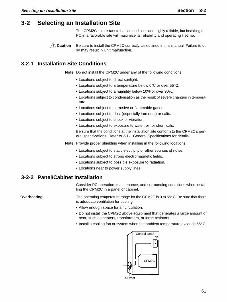
!
3-2SectionSelecting an Installation Site
61
3-2 Selecting an Installation SiteThe CPM2C is resistant to harsh conditions and highly reliable, but installing thePC in a favorable site will maximize its reliability and operating lifetime.
Caution Be sure to install the CPM2C correctly, as outlined in this manual. Failure to doso may result in Unit malfunction.
3-2-1 Installation Site Conditions
Note Do not install the CPM2C under any of the following conditions.
• Locations subject to direct sunlight.
• Locations subject to a temperature below 0°C or over 55°C.
• Locations subject to a humidity below 10% or over 90%.
• Locations subject to condensation as the result of severe changes in tempera-ture.
• Locations subject to corrosive or flammable gases.
• Locations subject to dust (especially iron dust) or salts.
• Locations subject to shock or vibration.
• Locations subject to exposure to water, oil, or chemicals.
Be sure that the conditions at the installation site conform to the CPM2C’s gen-eral specifications. Refer to 2-1-1 General Specifications for details.
Note Provide proper shielding when installing in the following locations:
• Locations subject to static electricity or other sources of noise.
• Locations subject to strong electromagnetic fields.
• Locations subject to possible exposure to radiation.
• Locations near to power supply lines.
3-2-2 Panel/Cabinet InstallationConsider PC operation, maintenance, and surrounding conditions when instal-ling the CPM2C in a panel or cabinet.
The operating temperature range for the CPM2C is 0 to 55C. Be sure that thereis adequate ventilation for cooling.
• Allow enough space for air circulation.
• Do not install the CPM2C above equipment that generates a large amount ofheat, such as heaters, transformers, or large resistors.
• Install a cooling fan or system when the ambient temperature exceeds 55C.
Control panelFan
Air vent
CPM2C
Overheating

3-3SectionInstalling the CPM2C
62
• Orient the CPM2C as shown below when installing it.
Top
Bottom
Power lines and high-voltage equipment can cause electrical noise in the PC.• Do not install the CPM2C in a panel or cabinet with high-voltage equipment.• Allow at least 200 mm between the CPM2C and nearby power lines.
CPM2C
200 mm min.
200 mm min.
Ensure that the CPM2C can be accessed for normal operation and mainte-nance.• Provide a clear path to the CPM2C for operation and maintenance. High-volt-
age equipment or power lines could be dangerous if they are in the way duringroutine operations.
• The PC will be easiest to access if the panel or cabinet is installed about 1 to1.6 m above the floor.
• Separate the CPM2C by at least 100 mm from other devices.
Otherdevice
100 mm min.
Otherdevice
100 mm min.
3-3 Installing the CPM2CThis section describes how to install the CPM2C and connect Expansion Unitsand Expansion I/O Units. Refer to Appendix B for diagrams showing the dimen-sions of the Units.
3-3-1 Connecting UnitsUp to 5 Expansion I/O Units and Expansion Units can be connected to a CPM2CCPU Unit. Use the following procedure when connecting an Expansion I/O Unitor Expansion Unit.
Electrical Noise
Accessibility

3-3SectionInstalling the CPM2C
63
1, 2, 3... 1. Remove the cover from the CPU Unit’s or the last Expansion I/O Unit’s orExpansion Unit’s expansion I/O connector. If the cover is difficult to remove,use a flat-blade screwdriver to pry the cover from the expansion I/O connec-tor.
Expansion I/O con-nector cover
2. Align the Unit and CPU Unit (or previous Expansion I/O Unit or ExpansionUnit) so that the catches (top and bottom) on the connectors fit together.Press the Units together to connect them.
3. Lock the Units together by closing the locks (top and bottom) on the CPUUnit (or previous Expansion I/O Unit or Expansion Unit). Place the cover (in-cluded with the CPU Unit) on the last Unit’s expansion I/O connector.
Expansion I/Oconnector coverSlide to lock
Units together.

!
3-3SectionInstalling the CPM2C
64
3-3-2 CPM2C InstallationThe CPM2C can be installed on a 35-mm DIN track.
End Plates(PFP-M)
DIN Track
PFP-100N (1 m)PFP-50N (50 cm)PFP-100N2 (1 m)
InstallationLower the CPM2C so that the notch on the back of the PC catches the top of theDIN Track. Push the PC forward until the lock snaps into place.
4) Lock1) Pull down.
2) Insertonto track.
3) Push in onthe Unit.
Caution Be sure that the DIN Track is installed horizontally. Installing the Track verticallywill inhibit the airflow that cools the CPM2C and could cause overheating.
RemovalPry the lock down with a flat-blade screwdriver and pivot the PC upward toremove it.
Screwdriver
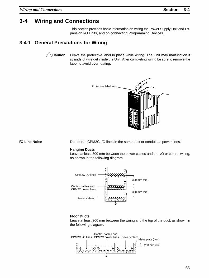
!
3-4SectionWiring and Connections
65
3-4 Wiring and ConnectionsThis section provides basic information on wiring the Power Supply Unit and Ex-pansion I/O Units, and on connecting Programming Devices.
3-4-1 General Precautions for Wiring
Caution Leave the protective label in place while wiring. The Unit may malfunction ifstrands of wire get inside the Unit. After completing wiring be sure to remove thelabel to avoid overheating.
Protective label
Do not run CPM2C I/O lines in the same duct or conduit as power lines.
Hanging DuctsLeave at least 300 mm between the power cables and the I/O or control wiring,as shown in the following diagram.
CPM2C I/O lines
Control cables andCPM2C power lines
Power cables
300 mm min.
300 mm min.
Floor DuctsLeave at least 200 mm between the wiring and the top of the duct, as shown inthe following diagram.
200 mm min.
Metal plate (iron)CPM2C I/O lines
Control cables andCPM2C power lines Power cables
I/O Line Noise
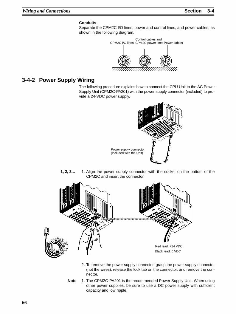
3-4SectionWiring and Connections
66
ConduitsSeparate the CPM2C I/O lines, power and control lines, and power cables, asshown in the following diagram.
CPM2C I/O linesControl cables andCPM2C power lines Power cables
3-4-2 Power Supply WiringThe following procedure explains how to connect the CPU Unit to the AC PowerSupply Unit (CPM2C-PA201) with the power supply connector (included) to pro-vide a 24-VDC power supply.
Power supply connector(included with the Unit)
1, 2, 3... 1. Align the power supply connector with the socket on the bottom of theCPM2C and insert the connector.
Red lead: +24 VDC
Black lead: 0 VDC
2. To remove the power supply connector, grasp the power supply connector(not the wires), release the lock tab on the connector, and remove the con-nector.
Note 1. The CPM2C-PA201 is the recommended Power Supply Unit. When usingother power supplies, be sure to use a DC power supply with sufficientcapacity and low ripple.
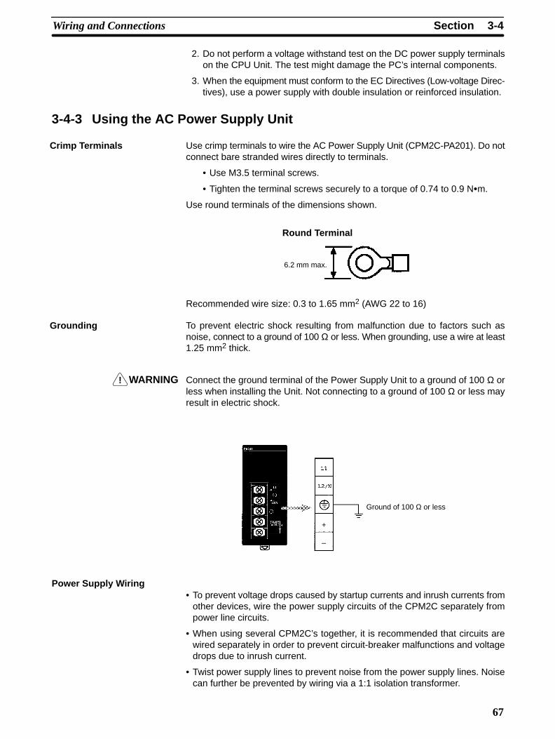
!
3-4SectionWiring and Connections
67
2. Do not perform a voltage withstand test on the DC power supply terminalson the CPU Unit. The test might damage the PC’s internal components.
3. When the equipment must conform to the EC Directives (Low-voltage Direc-tives), use a power supply with double insulation or reinforced insulation.
3-4-3 Using the AC Power Supply Unit
Use crimp terminals to wire the AC Power Supply Unit (CPM2C-PA201). Do notconnect bare stranded wires directly to terminals.
• Use M3.5 terminal screws.
• Tighten the terminal screws securely to a torque of 0.74 to 0.9 Nm.
Use round terminals of the dimensions shown.
Round Terminal
6.2 mm max.
Recommended wire size: 0.3 to 1.65 mm2 (AWG 22 to 16)
To prevent electric shock resulting from malfunction due to factors such asnoise, connect to a ground of 100 Ω or less. When grounding, use a wire at least1.25 mm2 thick.
WARNING Connect the ground terminal of the Power Supply Unit to a ground of 100 Ω orless when installing the Unit. Not connecting to a ground of 100 Ω or less mayresult in electric shock.
Ground of 100 Ω or less
+
–
Power Supply Wiring• To prevent voltage drops caused by startup currents and inrush currents from
other devices, wire the power supply circuits of the CPM2C separately frompower line circuits.
• When using several CPM2C’s together, it is recommended that circuits arewired separately in order to prevent circuit-breaker malfunctions and voltagedrops due to inrush current.
• Twist power supply lines to prevent noise from the power supply lines. Noisecan further be prevented by wiring via a 1:1 isolation transformer.
Crimp Terminals
Grounding
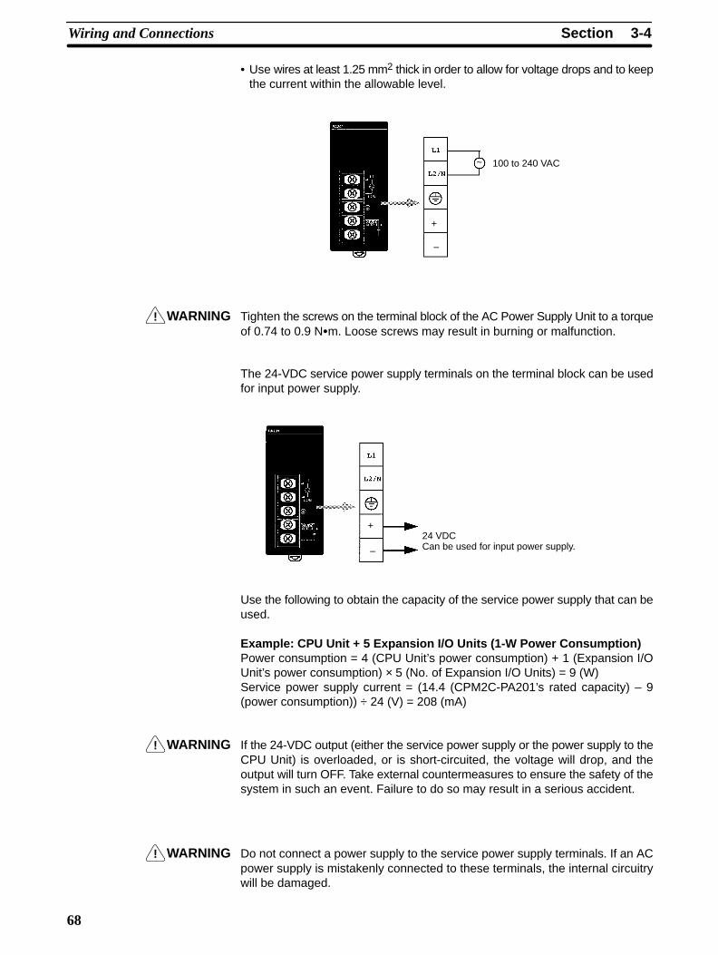
!
!
!
3-4SectionWiring and Connections
68
• Use wires at least 1.25 mm2 thick in order to allow for voltage drops and to keepthe current within the allowable level.
100 to 240 VAC
+
–
~
WARNING Tighten the screws on the terminal block of the AC Power Supply Unit to a torqueof 0.74 to 0.9 Nm. Loose screws may result in burning or malfunction.
The 24-VDC service power supply terminals on the terminal block can be usedfor input power supply.
24 VDCCan be used for input power supply.
+
–
Use the following to obtain the capacity of the service power supply that can beused.
Example: CPU Unit + 5 Expansion I/O Units (1-W Power Consumption)Power consumption = 4 (CPU Unit’s power consumption) + 1 (Expansion I/OUnit’s power consumption) × 5 (No. of Expansion I/O Units) = 9 (W)Service power supply current = (14.4 (CPM2C-PA201’s rated capacity) – 9(power consumption)) ÷ 24 (V) = 208 (mA)
WARNING If the 24-VDC output (either the service power supply or the power supply to theCPU Unit) is overloaded, or is short-circuited, the voltage will drop, and theoutput will turn OFF. Take external countermeasures to ensure the safety of thesystem in such an event. Failure to do so may result in a serious accident.
WARNING Do not connect a power supply to the service power supply terminals. If an ACpower supply is mistakenly connected to these terminals, the internal circuitrywill be damaged.
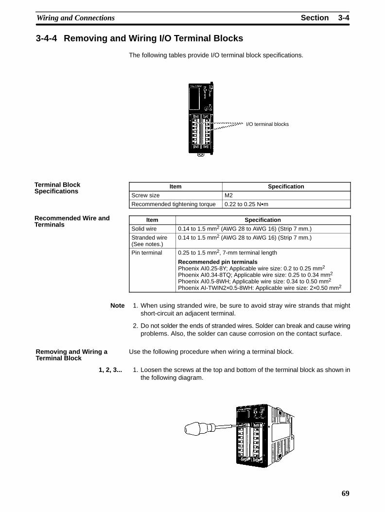
3-4SectionWiring and Connections
69
3-4-4 Removing and Wiring I/O Terminal Blocks
The following tables provide I/O terminal block specifications.
I/O terminal blocks
Item Specification
Screw size M2
Recommended tightening torque 0.22 to 0.25 Nm
Item Specification
Solid wire 0.14 to 1.5 mm2 (AWG 28 to AWG 16) (Strip 7 mm.)
Stranded wire(See notes.)
0.14 to 1.5 mm2 (AWG 28 to AWG 16) (Strip 7 mm.)
Pin terminal 0.25 to 1.5 mm2, 7-mm terminal length
Recommended pin terminalsPhoenix AI0.25-8Y; Applicable wire size: 0.2 to 0.25 mm2
Phoenix AI0.34-8TQ; Applicable wire size: 0.25 to 0.34 mm2
Phoenix AI0.5-8WH; Applicable wire size: 0.34 to 0.50 mm2
Phoenix AI-TWIN2×0.5-8WH: Applicable wire size: 2×0.50 mm2
Note 1. When using stranded wire, be sure to avoid stray wire strands that mightshort-circuit an adjacent terminal.
2. Do not solder the ends of stranded wires. Solder can break and cause wiringproblems. Also, the solder can cause corrosion on the contact surface.
Use the following procedure when wiring a terminal block.
1, 2, 3... 1. Loosen the screws at the top and bottom of the terminal block as shown inthe following diagram.
Terminal BlockSpecifications
Recommended Wire andTerminals
Removing and Wiring aTerminal Block

3-4SectionWiring and Connections
70
2. Pull the terminal block out of the Unit.
3. Insert each lead wire into the terminal block and tighten that terminal’sscrew.
4. After wiring the terminal block, insert the block into the Unit and tighten thescrews at the top and bottom of the terminal block.
3-4-5 Removing and Wiring I/O ConnectorsThe following tables provide specifications of compatible I/O connectors.
I/O connectors

3-4SectionWiring and Connections
71
Compatible Connector Specifications (OMRON)
Connector Specifications Model number
24-pin solderedconnector and cover
Connector: Fujitsu FCN-361J024-AU equivalentCover: Fujitsu FCN-360C024-J2 equivalent
C500-CE241
24-pin crimpconnector and cover
Housing: Fujitsu FCN-363J024 equivalentContacts: Fujitsu FCN-363J-AU equivalentCover: Fujitsu FCN-360C024-J2 equivalent
C500-CE242
24-pin pressureconnector
Connector: Fujitsu FCN-367J024-AU/F equivalent C500-CE243
Connector Specifications (Fujitsu)
Item Specifications Model number
Soldered jack 24-pin gold-plated terminals FCN-361J024-AU
Crimp Crimp jack housing 24-pin FCN-363J024connector Crimp contacts For wire gauges 24 AWG to 28 AWG FCN-363J-AU
Hand crimp tool --- FCN-363T-T005/H
Contact removal tool --- FCN-360T-T001/H
Pressure Pressure jack with closed 24-pin gold-plated terminals FCN-367J024-AU/Fconnector end cover 24-pin silver-plated terminals FCN-367J024-AG/F
Pressure jack with open end 24-pin gold-plated terminals FCN-367J024-AU/Hcover 24-pin silver-plated terminals FCN-367J024-AG/H
Pressing Hand press General purpose FCN-707T-T101/Htools Cable cutter General purpose FCN-707T-T001/H
Locator plate For the 360-series connectors FCN-367T-T012/H
Connector cover Thin slanted cover for 24-pin connector FCN-360C024-J2(Not compatible with the closed-end coverpressure jack.)
With slotted screws for 24-pin connector(Can be turned by hand.)
FCN-360C024E
With Phillips-head screws for 24-pin connector FCN-360C024B
With intermediate Phillips-head screws for 24-pinconnector
FCN-360C024C
Use the following procedure when connecting a pressure connector.
1, 2, 3... 1. Align the connector and insert it into the Unit.
Connecting I/O Connectors(Pressure Connectors)
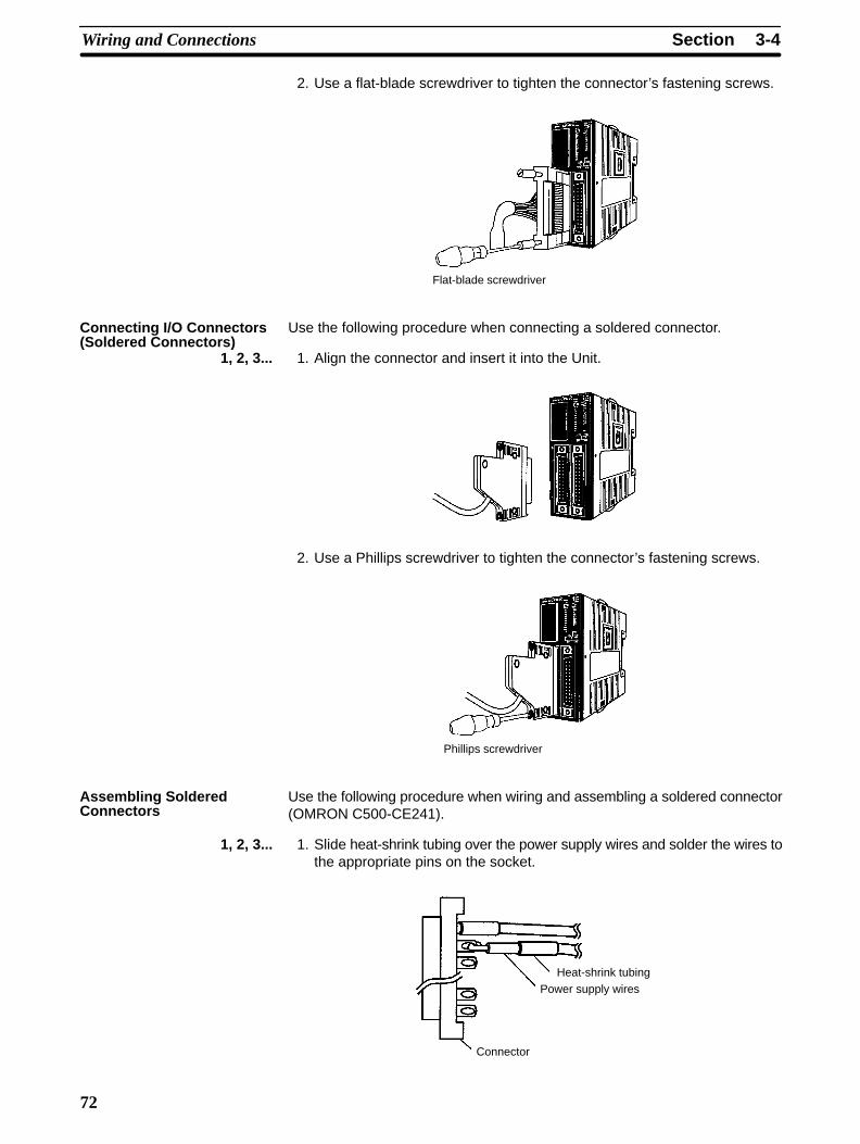
3-4SectionWiring and Connections
72
2. Use a flat-blade screwdriver to tighten the connector’s fastening screws.
Flat-blade screwdriver
Use the following procedure when connecting a soldered connector.
1, 2, 3... 1. Align the connector and insert it into the Unit.
2. Use a Phillips screwdriver to tighten the connector’s fastening screws.
Phillips screwdriver
Use the following procedure when wiring and assembling a soldered connector(OMRON C500-CE241).
1, 2, 3... 1. Slide heat-shrink tubing over the power supply wires and solder the wires tothe appropriate pins on the socket.
Heat-shrink tubingPower supply wires
Connector
Connecting I/O Connectors(Soldered Connectors)
Assembling SolderedConnectors
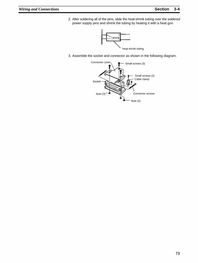
3-4SectionWiring and Connections
73
2. After soldering all of the pins, slide the heat-shrink tubing over the solderedpower supply pins and shrink the tubing by heating it with a heat gun.
Heat-shrink tubing
3. Assemble the socket and connector as shown in the following diagram.
Connector cover
Socket
Nuts (3)
Nuts (2)
Connector screws
Small screws (2)Cable clamp
Small screws (3)

3-4SectionWiring and Connections
74
3-4-6 Using I/O Terminals and Relay TerminalsWe recommend using the following I/O Terminals and Relay Terminals to wiredevices to the CPM2C’s I/O connector.
Outputs Inputs
Cables (See note.)
XW2Z-AG79-C
Terminal BlocksXW2B-20G4 (M3 screws)XW2B-20G5 (M3.5 screws)
Cables (See note.)
XW2Z-A
Relay Terminals
G7TC-ID16G7TC-IA16
Cables (See note.)
XW2Z-AG79-C
Terminal BlocksXW2B-20G4 (M3 screws)XW2B-20G5 (M3.5 screws)
Cables
G79-CRelay Terminals
G7OD-OC16G7OD-OC16-1G7OD-SOC16G7OD-SOC16-1G7OD-FOM16G7OD-FOM16-1
Cables
G79-CG2R-1-S(N)
Relay Terminals
G7TC-OC08
Relay Terminals
G7OA-ZOC16-3G7OA-ZOC16-4
Note The allowable current forthe XW2Z-A is 1 A.Do not allow the current onthe common terminal toexceed 1 A.
Cables
G79-C
Terminal BlocksXW2C-20G5-IN16 (M3.5 screws)
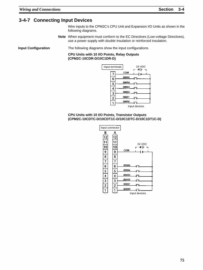
3-4SectionWiring and Connections
75
3-4-7 Connecting Input DevicesWire inputs to the CPM2C’s CPU Unit and Expansion I/O Units as shown in thefollowing diagrams.
Note When equipment must conform to the EC Directives (Low-voltage Directives),use a power supply with double insulation or reinforced insulation.
The following diagrams show the input configurations.
CPU Units with 10 I/O Points, Relay Outputs(CPM2C-10CDR-D/10C1DR-D)
Input devices
24 VDCInput terminals
CPU Units with 10 I/O Points, Transistor Outputs(CPM2C-10CDTC-D/10CDT1C-D/10C1DTC-D/10C1DT1C-D)
Input devices
24 VDC
Input connector
Input Configuration
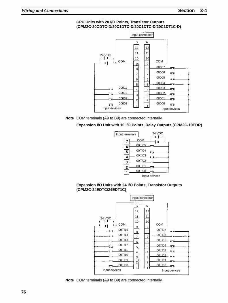
3-4SectionWiring and Connections
76
CPU Units with 20 I/O Points, Transistor Outputs(CPM2C-20CDTC-D/20C1DTC-D/20C1DTC-D/20C1DT1C-D)
Input connector
Input devices Input devices
24 VDC
COM COM
00011
00010
00009
00008
00007
00006
00005
00004
00003
00002
00001
00000
B A
12
11
10
9
8
7
6
5
4
3
2
1
12
11
10
9
8
7
6
5
4
3
2
1
Note COM terminals (A9 to B9) are connected internally.
Expansion I/O Unit with 10 I/O Points, Relay Outputs (CPM2C-10EDR)
Input devices
24 VDCInput terminals
COM
0005
0004
0003
0002
0001
0000
Expansion I/O Units with 24 I/O Points, Transistor Outputs(CPM2C-24EDTC/24EDT1C)
Input connector
Input devices Input devices
24 VDC
COM COM
0011
0010
0009
0008
0007
0006
0005
0004
0003
0002
0001
0000
0012
0013
0014
0015
B A
12
11
10
9
8
7
6
5
4
3
2
1
12
11
10
9
8
7
6
5
4
3
2
1
Note COM terminals (A9 to B9) are connected internally.
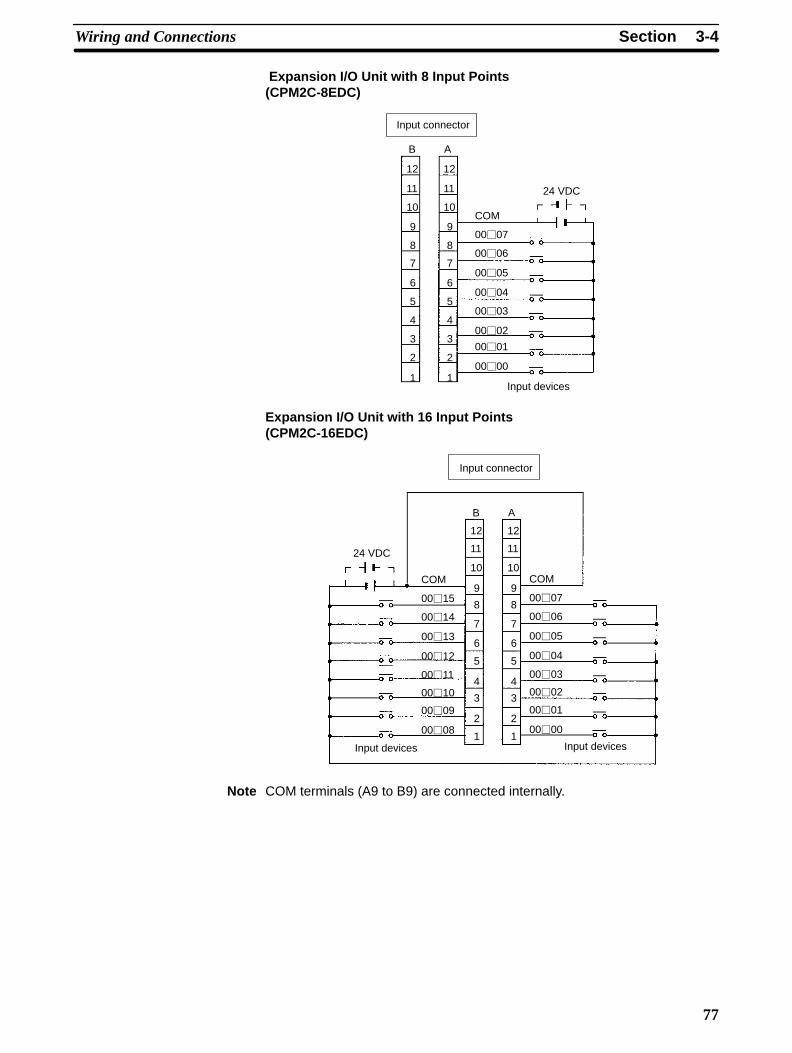
3-4SectionWiring and Connections
77
Expansion I/O Unit with 8 Input Points(CPM2C-8EDC)
Input connector
Input devices
24 VDC
COM
0007
0006
0005
0004
0003
0002
0001
0000
B A
12
11
10
9
8
7
6
5
4
3
2
1
12
11
10
9
8
7
6
5
4
3
2
1
Expansion I/O Unit with 16 Input Points(CPM2C-16EDC)
Input connector
Input devices Input devices
24 VDC
COM
0015
0014
0013
0012
0011
0010
0009
0008
COM
0007
0006
0005
0004
0003
0002
0001
0000
B A
12
11
10
9
8
7
6
5
4
3
2
1
12
11
10
9
8
7
6
5
4
3
2
1
Note COM terminals (A9 to B9) are connected internally.
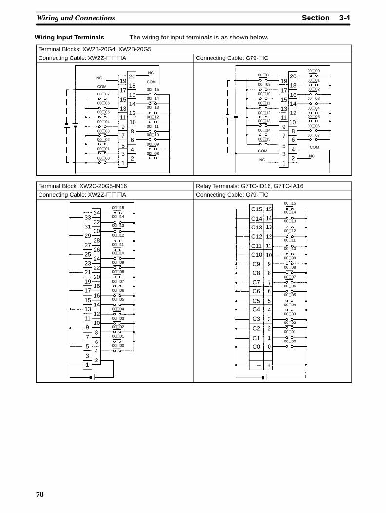
3-4SectionWiring and Connections
78
The wiring for input terminals is as shown below.
Terminal Blocks: XW2B-20G4, XW2B-20G5
Connecting Cable: XW2Z-A Connecting Cable: G79-C
COM
0007
0006
0005
0004
0003
0002
0001
0000
COM
0015
0014
0013
0012
0011
0010
0009
0008
NCNC
19
17
15
13
11
9
7
53
1
20
18
16
14
12
10
8
6
4
2
COM
0007
0006
0005
0004
0003
0002
0001
0000
COM
0015
0014
0013
0012
0011
0010
0009
0008
NCNC
19
17
15
13
11
9
7
53
1
20
18
16
14
12
10
8
6
4
2
Terminal Block: XW2C-20G5-IN16 Relay Terminals: G7TC-ID16, G7TC-IA16
Connecting Cable: XW2Z-A Connecting Cable: G79-C
0015
0014
0013
0012
0011
0010
0009
0008
0007
0006
0005
0004
0003
0002
0001
0000
33
31
29
27
25
23
21
19
17
15
13
11
9
7
5
3
1
34
32
30
28
26
24
22
20
18
16
14
12
10
8
6
4
2
0015
0014
0013
0012
0011
0010
0009
0008
0007
0006
0005
0004
0003
0002
0001
0000
C15
C14
C13
C12
C11
C10
C9
C8
C7
C6
C5
C4
C2
C1
C0
C3
15
14
13
12
11
10
9
8
7
6
5
4
3
2
1
0
+–
Wiring Input Terminals

3-4SectionWiring and Connections
79
The following table shows how to connect various input devices.
Device Circuit diagram
Relay output
IN
COM (+)
5 mA/6 mA/8 mACPM2C
NPN open collector
IN
COM (+)
Sensorpower supply
Output
5 mA/6 mA/8 mACPM2C
0 V
NPN current output Use the same power supply forthe input and sensor.
CPM2CIN
COM (+)
Output
5 mA/6 mA/8 mA
0 V
Constantcurrentcircuit
+
PNP current outputSensor powersupply
COM (–)0 V
INOutput
5 mA/6 mA/8 mACPM2C
Voltage output
Sensor powersupply
IN
COM (+)
0 V
OutputCPM2C
Note Do not use the following wiring with voltage-output devices:
COM(+)
IN0 V
OutputCPM2C
Sensor powersupply
Incorrect Wiring
Input Devices

3-4SectionWiring and Connections
80
High-speed Counter InputsUsing IR 00000 to IR 00002 as High-speed Counter InputsIn these examples, Encoders with an external 24-VDC open-collector output areconnected.
Differential Phase Mode(Count frequency: 5 kHz)
Encoder
24 VDC
00000 A-phase input
00001 B-phase input
COM
00002 Z-phase input
Pulse Plus Direction Input Mode(Count frequency: 20 kHz)
Encoder
24 VDC
00000 Pulse input
00001 Direction input
COM
00002 Reset input
Sensor or switch
CPM2C CPM2C
Up/Down Mode(Count frequency: 20 kHz)
24 VDC
00000 CW input*
00001 CCW input*
COM
00002 Reset input
Increment Mode(Count frequency: 20 kHz)
Encoder
24 VDC
00000 Pulse input
00001 Normal input
COM
00002 Normal input
CPM2C CPM2C
Sensor
Sensor
Sensor or switch
Sensor or switch
Note *CW is clockwise and CCW is counter-clockwise.
Using IR 00003 to IR 00006 as Interrupt Inputs (Counter Mode)In these examples, an Encoder with an external 24-VDC open-collector output isconnected.
Increment or decrement(Count frequency: 2 kHz)
Encoder
24 VDC
Input (00003 to 00006)
COM
CPM2C
The input bits shown in the following tables can operate as normal inputs or theycan be assigned special functions in the PC Setup.Special functions for input bits IR 00000 through IR 00002 are set in DM 6642:
Bit PC Setup setting (DM 6642 bits 08 to15)address 00 01 02, 03, or 04
IR 00000 Used as normal Used as high-speed Used as inputs for
IR 00001inputs. counter inputs. synchronized pulse
control.
IR 00002 Used as a normal input.
PC Setup Settings
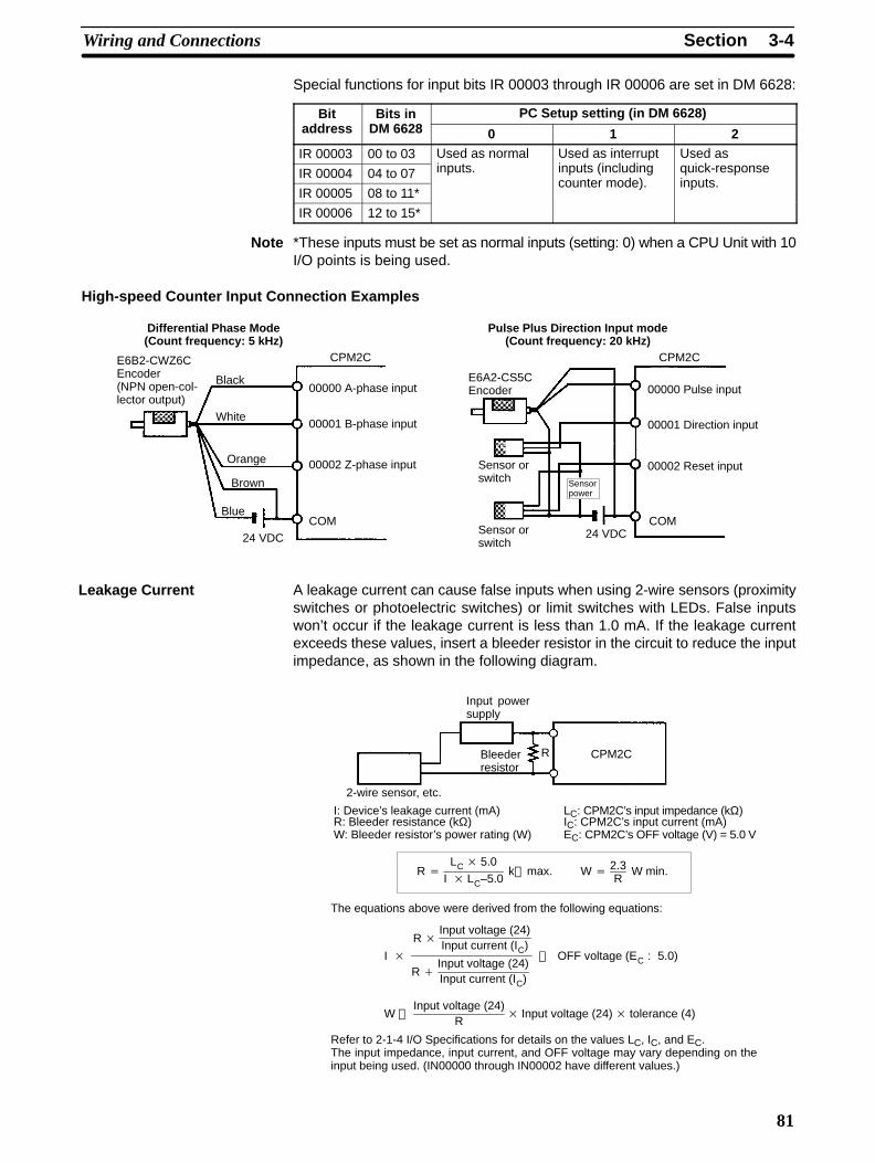
3-4SectionWiring and Connections
81
Special functions for input bits IR 00003 through IR 00006 are set in DM 6628:
Bit Bits in PC Setup setting (in DM 6628)address DM 6628 0 1 2
IR 00003 00 to 03 Used as normal Used as interrupt Used as
IR 00004 04 to 07 inputs. inputs (including quick-response
IR 00005 08 to 11*counter mode). inputs.
IR 00006 12 to 15*
Note *These inputs must be set as normal inputs (setting: 0) when a CPU Unit with 10I/O points is being used.
High-speed Counter Input Connection Examples
Differential Phase Mode(Count frequency: 5 kHz)
E6B2-CWZ6CEncoder(NPN open-col-lector output)
24 VDC
00000 A-phase input
00001 B-phase input
COM
00002 Z-phase input
Pulse Plus Direction Input mode(Count frequency: 20 kHz)
E6A2-CS5CEncoder
24 VDC
00000 Pulse input
00001 Direction input
COM
00002 Reset inputSensor orswitch
CPM2C CPM2C
Sensor orswitch
Sensorpower
Black
White
Orange
Brown
Blue
A leakage current can cause false inputs when using 2-wire sensors (proximityswitches or photoelectric switches) or limit switches with LEDs. False inputswon’t occur if the leakage current is less than 1.0 mA. If the leakage currentexceeds these values, insert a bleeder resistor in the circuit to reduce the inputimpedance, as shown in the following diagram.
R CPM2C
Input powersupply
Bleederresistor
2-wire sensor, etc.
I: Device’s leakage current (mA)R: Bleeder resistance (kΩ)W: Bleeder resistor’s power rating (W)
The equations above were derived from the following equations:
LC: CPM2C’s input impedance (kΩ)IC: CPM2C’s input current (mA)EC: CPM2C’s OFF voltage (V) = 5.0 V
R LC 5.0
I LC–5.0k max. W
2.3R
W min.
I
R Input voltage (24)Input current (IC)
R Input voltage (24)Input current (IC)
OFF voltage (EC : 5.0)
W Input voltage (24)
R Input voltage (24) tolerance (4)
Refer to 2-1-4 I/O Specifications for details on the values LC, IC, and EC.The input impedance, input current, and OFF voltage may vary depending on theinput being used. (IN00000 through IN00002 have different values.)
Leakage Current
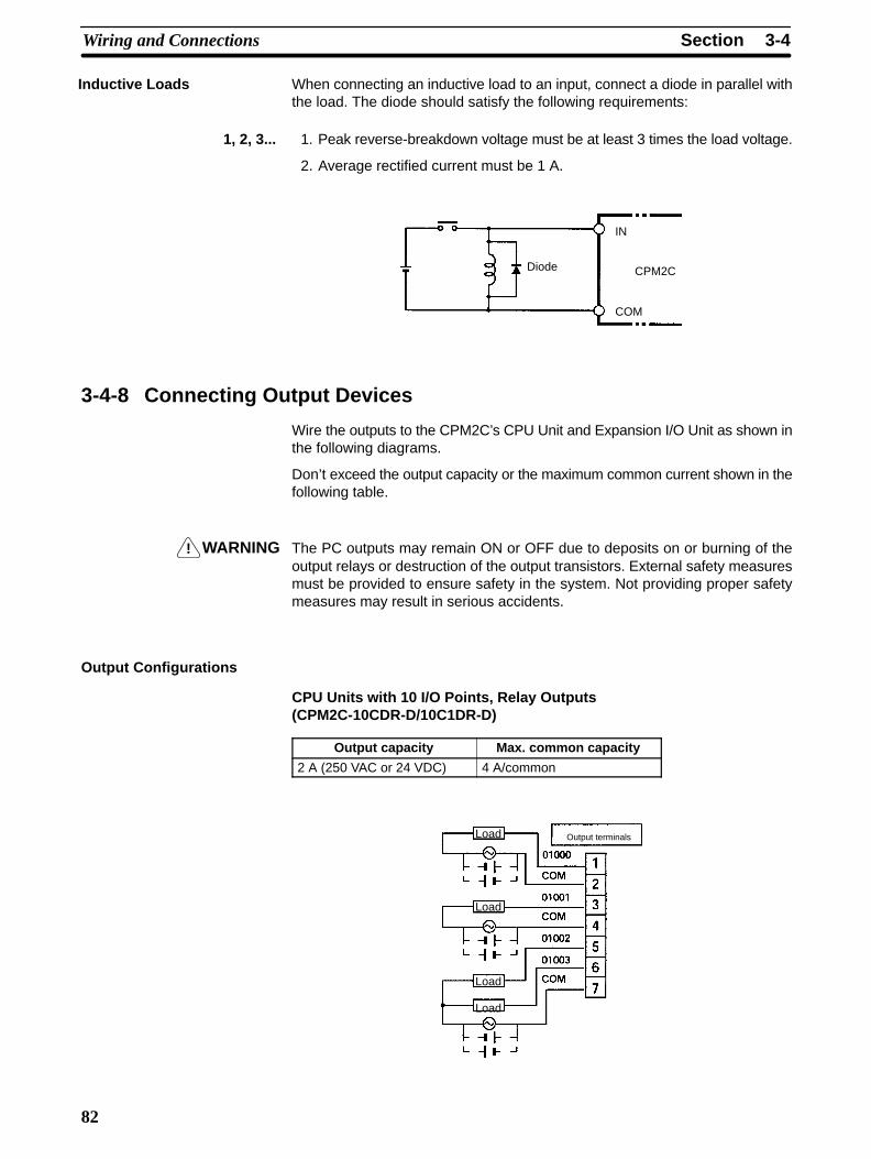
!
3-4SectionWiring and Connections
82
When connecting an inductive load to an input, connect a diode in parallel withthe load. The diode should satisfy the following requirements:
1, 2, 3... 1. Peak reverse-breakdown voltage must be at least 3 times the load voltage.
2. Average rectified current must be 1 A.
IN
COM
CPM2CDiode
3-4-8 Connecting Output Devices
Wire the outputs to the CPM2C’s CPU Unit and Expansion I/O Unit as shown inthe following diagrams.
Don’t exceed the output capacity or the maximum common current shown in thefollowing table.
WARNING The PC outputs may remain ON or OFF due to deposits on or burning of theoutput relays or destruction of the output transistors. External safety measuresmust be provided to ensure safety in the system. Not providing proper safetymeasures may result in serious accidents.
Output Configurations
CPU Units with 10 I/O Points, Relay Outputs(CPM2C-10CDR-D/10C1DR-D)
Output capacity Max. common capacity
2 A (250 VAC or 24 VDC) 4 A/common
Output terminalsLoad
Load
Load
Load
Inductive Loads
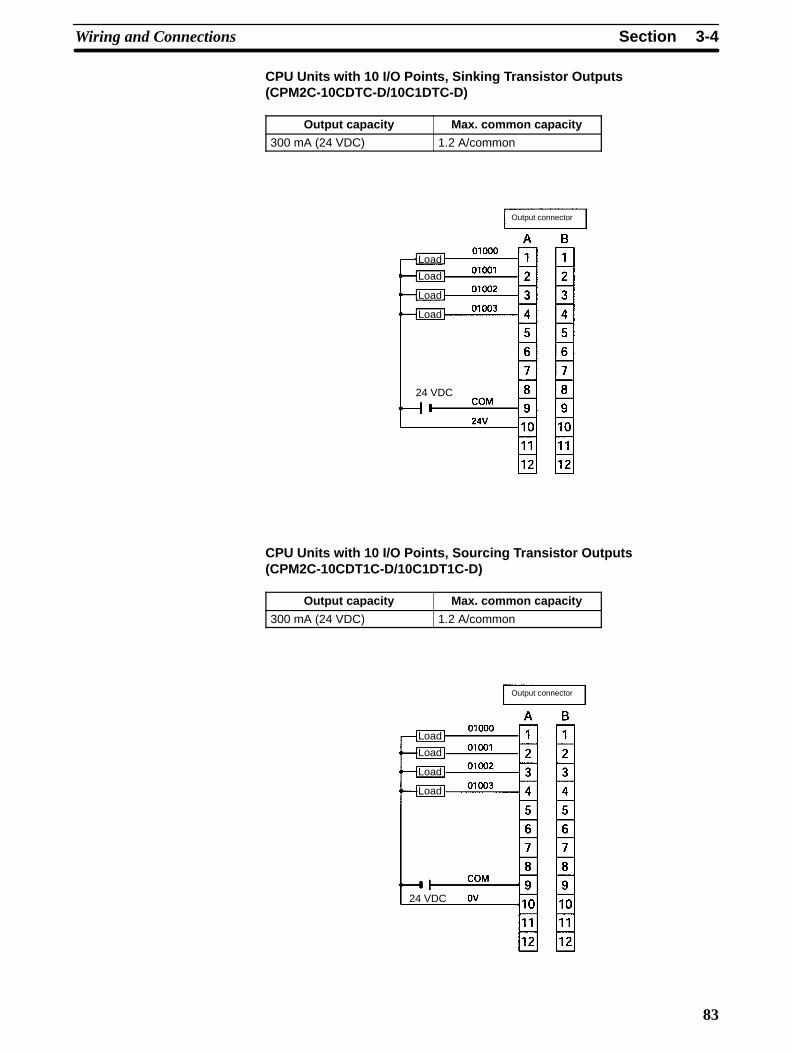
3-4SectionWiring and Connections
83
CPU Units with 10 I/O Points, Sinking Transistor Outputs(CPM2C-10CDTC-D/10C1DTC-D)
Output capacity Max. common capacity
300 mA (24 VDC) 1.2 A/common
Output connector
Load
Load
Load
Load
24 VDC
CPU Units with 10 I/O Points, Sourcing Transistor Outputs(CPM2C-10CDT1C-D/10C1DT1C-D)
Output capacity Max. common capacity
300 mA (24 VDC) 1.2 A/common
Output connector
Load
Load
Load
Load
24 VDC
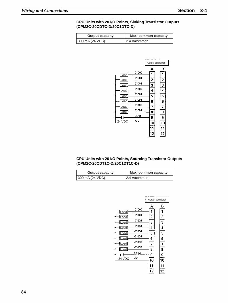
3-4SectionWiring and Connections
84
CPU Units with 20 I/O Points, Sinking Transistor Outputs(CPM2C-20CDTC-D/20C1DTC-D)
Output capacity Max. common capacity
300 mA (24 VDC) 2.4 A/common
Output connector
Load
Load
Load
Load
24 VDC
Load
Load
Load
Load
CPU Units with 20 I/O Points, Sourcing Transistor Outputs(CPM2C-20CDT1C-D/20C1DT1C-D)
Output capacity Max. common capacity
300 mA (24 VDC) 2.4 A/common
Output connector
Load
Load
Load
Load
24 VDC
Load
Load
Load
Load
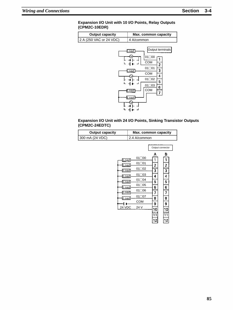
3-4SectionWiring and Connections
85
Expansion I/O Unit with 10 I/O Points, Relay Outputs(CPM2C-10EDR)
Output capacity Max. common capacity
2 A (250 VAC or 24 VDC) 4 A/common
Output terminalsLoad
Load
Load
Load
0100
COM
COM
COM
0101
0102
0103
Expansion I/O Unit with 24 I/O Points, Sinking Transistor Outputs(CPM2C-24EDTC)
Output capacity Max. common capacity
300 mA (24 VDC) 2.4 A/common
Output connector
Load
Load
Load
Load
24 VDC
Load
Load
Load
Load
0100
COM
0101
0102
0103
0104
0105
0106
0107
24 V

3-4SectionWiring and Connections
86
Expansion I/O Unit with 24 I/O Points, Sourcing Transistor Outputs(CPM2C-24EDT1C)
Output capacity Max. common capacity
300 mA (24 VDC) 2.4 A/common
Output connector
Load
Load
Load
Load
24 VDC
Load
Load
Load
Load
0100
COM
0101
0102
0103
0104
0105
0106
0107
0 V
Expansion I/O Unit with 8 Output Points, Relay Outputs(CPM2C-8ER)
Output capacity Max. common capacity
2 A (250 VAC/24 VDC) 4 A/common
Output terminals
Load
Load
Load
Load
Load
Load
Load
Load
COM
0103
0102
COM
0101
COM
0100 COM
COM
0106
0107
0104
COM
0105
7
6
5
4
3
2
1
1
2
3
4
5
6
7

3-4SectionWiring and Connections
87
Expansion I/O Unit with 8 Output Points, Sinking Transistor Outputs(CPM2C-8ETC)
Output capacity Max. common capacity
300 mA (24 VDC) 2.4 A/common
Output connector
0103
0102
0101
0100
COM
0106
0107
0104
0105
Load
24 VDC 24V
Load
Load
Load
Load
Load
Load
Load
1
2
3
4
5
6
7
B
8
9
10
11
12
1
2
3
4
5
6
7
A
8
9
10
11
12
Expansion I/O Unit with 8 Output Points, Sourcing Transistor Outputs(CPM2C-8ET1C)
Output capacity Max. common capacity
300 mA (24 VDC) 2.4 A/common
0103
0102
0101
0100
COM
0106
0107
0104
0105
Load
24 VDC 0V
Load
Load
Load
Load
Load
Load
Load
Output connector
1
2
3
4
5
6
7
B
8
9
10
11
12
1
2
3
4
5
6
7
A
8
9
10
11
12

3-4SectionWiring and Connections
88
Expansion I/O Unit with 16 Output Points, Sinking Transistor Outputs(CPM2C-16ETC)
Output capacity Max. common capacity
00 to 07: 300 mA (24 VDC)08 to 15: 100 mA (24 VDC)
3.2 A/common
0103
0102
0101
0100
COM
0106
0107
0104
0105
Load
24 VDC24V
Load
Load
Load
Load
Load
Load
Load
Output connector
0111
0110
0109
0108
COM
0114
0115
0112
0113
24V
Load
Load
Load
Load
Load
Load
Load
Load
1
2
3
4
5
6
7
B
8
9
10
11
12
1
2
3
4
5
6
7
A
8
9
10
11
12
Note Wire COM terminals (A9 and B9) and 24-V terminals (A10 and B10) even thoughthey are connected internally.
Expansion I/O Unit with 16 Output Points, Sourcing Transistor Outputs(CPM2C-16ET1C)
Output capacity Max. common capacity
00 to 07: 300 mA (24 VDC)08 to 15: 100 mA (24 VDC)
3.2 A/common
0103
0102
0101
0100
COM
0106
0107
0104
0105
Load
24 VDC0V
Load
Load
Load
Load
Load
Load
Load
Output connector
0111
0110
0109
0108
COM
0114
0115
0112
0113
0V
Load
Load
Load
Load
Load
Load
Load
Load
1
2
3
4
5
6
7
B
8
9
10
11
12
1
2
3
4
5
6
7
A
8
9
10
11
12
Note Wire COM terminals (A9 and B9) and 0-V terminals (A10 and B10) even thoughthey are connected internally.

3-4SectionWiring and Connections
89
Wiring Output TerminalsThe wiring for output terminals is as shown below.
Terminal Blocks: XW2B-20G4, XW2B-20G5; Connecting Cable: XW2Z-A
Sinking transistor outputs Sourcing transistor outputs
0103
0102
0101
0100
0106
0107
0104
0105
0111
0110
0109
0108
0114
0115
0112
0113
COMCOM
19
17
15
13
11
9
7
53
1
20
18
16
14
12
10
8
6
4
2
0103
0102
0101
0100
0106
0107
0104
0105
0111
0110
0109
0108
0114
0115
0112
0113
COMCOM
19
17
15
13
11
9
7
53
1
20
18
16
14
12
10
8
6
4
2
Terminal Blocks: XW2B-20G4, XW2B-20G5; Connecting Cable: G79-C
Sinking outputs Sourcing outputs
0103
0102
0101
0100
0106
0107
0104
0105
0111
0110
0109
0108
0114
0115
0112
0113
COMCOM
19
17
15
13
11
9
7
5
3
1
20
18
16
14
12
10
8
6
4
2
0103
0102
0101
0100
0106
0107
0104
0105
0111
0110
0109
0108
0114
0115
0112
0113
COMCOM
19
17
15
13
11
9
7
5
3
1
20
18
16
14
12
10
8
6
4
2
Relay Terminals: G70A-ZOC16-3 (sinking outputs), G70A-ZOC16-4 (sourcing outputs)
Connecting Cables: G79- C, G2R-1-S(N)
N. O. contacts
N. C. contacts Pow
er s
uppl
y
L1 L2 L3 L4 L5 L6 L7 L8 L9 L10
L11
L12
L13
L14
L15
L16
L17
L18
L19
L20
L21
L22
L23
L24
L25
L26
L27
L28
L29
L30
L31
L32
+ –
01
00
N.O
.
N.C
.
N.O
.
N.C
.
N.O
.
N.C
.
N.O
.
N.C
.
N.O
.
N.C
.
N.O
.
N.C
.
N.O
.
N.C
.
N.O
.
N.C
.
N.O
.
N.C
.
N.O
.
N.C
.
N.O
.
N.C
.
N.O
.
N.C
.
N.O
.
N.C
.
N.O
.
N.C
.
N.O
.
N.C
.
N.O
.
N.C
.
01
00
01
01
01
01
01
02
01
02
01
03
01
03
01
04
01
04
01
05
01
05
01
06
01
06
01
07
01
07
01
08
01
08
01
09
01
09
01
10
01
10
01
11
01
11
01
12
01
12
01
13
01
13
01
14
01
14
01
15
01
15
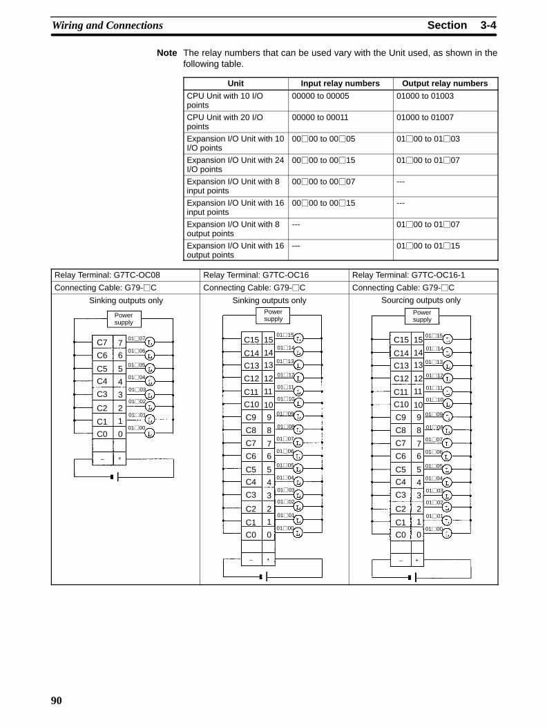
3-4SectionWiring and Connections
90
Note The relay numbers that can be used vary with the Unit used, as shown in thefollowing table.
Unit Input relay numbers Output relay numbers
CPU Unit with 10 I/Opoints
00000 to 00005 01000 to 01003
CPU Unit with 20 I/Opoints
00000 to 00011 01000 to 01007
Expansion I/O Unit with 10I/O points
0000 to 0005 0100 to 0103
Expansion I/O Unit with 24I/O points
0000 to 0015 0100 to 0107
Expansion I/O Unit with 8input points
0000 to 0007 ---
Expansion I/O Unit with 16input points
0000 to 0015 ---
Expansion I/O Unit with 8output points
--- 0100 to 0107
Expansion I/O Unit with 16output points
--- 0100 to 0115
Relay Terminal: G7TC-OC08 Relay Terminal: G7TC-OC16 Relay Terminal: G7TC-OC16-1
Connecting Cable: G79-C Connecting Cable: G79-C Connecting Cable: G79-C
Sinking outputs only
Powersupply
0103
0102
0101
0100
0106
0107
0104
0105
+–
C7
C6
C5
C4
C2
C1
C0
C3
7
6
5
4
3
2
1
0
Sinking outputs only
0103
0102
0101
0100
0106
0107
0104
0105
0111
0110
0109
0108
0114
0115
0112
0113
Powersupply
+–
C15
C14
C13
C12
C11
C10
C9
C8
C7
C6
C5
C4
C2
C1
C0
C3
15
14
13
12
11
10
9
8
7
6
5
4
3
2
1
0
Sourcing outputs only
0103
0102
0101
0100
0106
0107
0104
0105
0111
0110
0109
0108
0114
0115
0112
0113
Powersupply
+–
C15
C14
C13
C12
C11
C10
C9
C8
C7
C6
C5
C4
C2
C1
C0
C3
15
14
13
12
11
10
9
8
7
6
5
4
3
2
1
0

3-4SectionWiring and Connections
91
Relay Terminals: G70D-SOC16, G70D-FOM16 Relay Terminal: G70D-SOC16-1, G70D-FOM16-1
Connecting Cable: G79-C Connecting Cable: G79-C
Sinking outputs only
01030102
01010100
01060107
01040105
01110110
01090108
0114
0115
01120113
Powersupply
Powersupply
Powersupply
Powersupply
Powersupply
Powersupply
Powersupply
Powersupply
NCNC
NC
A0
A2
B0
B2
A4
A6
B2
B4
A8
A10
B4
B6
A12
A14
A1
A3
B1
B3
A5
A7
B3
B5
A9
A11
B5
B7
A13
A15
Sourcing outputs only
01030102
01010100
01060107
01040105
01110110
01090108
0114
0115
01120113
Powersupply
Powersupply
Powersupply
Powersupply
Powersupply
Powersupply
Powersupply
Powersupply
NCNC
NC
A0
A2
B0
B2
A4
A6
B2
B4
A8
A10
B4
B6
A12
A14
A1
A3
B1
B3
A5
A7
B3
B5
A9
A11
B5
B7
A13
A15
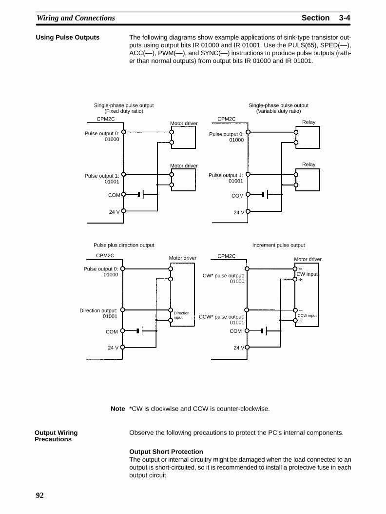
3-4SectionWiring and Connections
92
The following diagrams show example applications of sink-type transistor out-puts using output bits IR 01000 and IR 01001. Use the PULS(65), SPED(––),ACC(––), PWM(––), and SYNC(––) instructions to produce pulse outputs (rath-er than normal outputs) from output bits IR 01000 and IR 01001.
CPM2C
Single-phase pulse output(Fixed duty ratio)
Motor driver
Pulse output 0:01000
CPM2C
Pulse output 1:01001
COM
Motor driver
Single-phase pulse output(Variable duty ratio)
Relay
Pulse output 0:01000
CPM2C
Pulse output 1:01001
COM
Relay
Pulse plus direction output
Motor driver
Pulse output 0:01000
CPM2C
Direction output:01001
COM
Directioninput
Increment pulse output
Motor driver
CW* pulse output:01000
CCW* pulse output:01001
COM
CW input
CCW input
24 V 24 V
24 V 24 V
Note *CW is clockwise and CCW is counter-clockwise.
Observe the following precautions to protect the PC’s internal components.
Output Short ProtectionThe output or internal circuitry might be damaged when the load connected to anoutput is short-circuited, so it is recommended to install a protective fuse in eachoutput circuit.
Using Pulse Outputs
Output WiringPrecautions

3-4SectionWiring and Connections
93
Inductive LoadsWhen connecting an inductive load to an input, connect a surge protector ordiode in parallel with the load.
The surge protector’s components should have the following ratings:
OUT
COMCPM2C Surge protector
Relay Output
OUT
COM
CPM2CDiode
Relay OutputTransistor Output(Sinking)
OUT
COM
CPM2CDiode
Relay OutputTransistor Output(Sourcing)
The diode should satisfy the following requirements:
Peak reverse-breakdown voltage must be at least 3 times the load voltage.Average rectified current must be 1 A.
Inrush Current ConsiderationsWhen switching a load with a high inrush current in the CPM2C relay output ortransistor output model, such as an incandescent lamp, suppress the inrush cur-rent as shown below.
R
R
Countermeasure 1
Providing a dark current ofapprox. one-third of the ratedvalue through an incandescentlamp
Countermeasure 2
Providing a limiting resistor
OUT
COM
OUT
COM
Fuse InsertionThe CPM2C with transistor output may burn if the load is short-circuited, there-fore, insert a protective fuse in series to the load.

3-4SectionWiring and Connections
94
3-4-9 RS-422 Port ConnectionWhen using the RS-422/RS-232C Adapter Unit (CPM2C-CIF11) in a Host Linkconnection (1:N), wire the RS-422 port as shown below.
Host
RS-232C
B500-AL004 CPM2C-CIF11
RS-422
CPM2C-CIF11
NT-AL001
FG 7
3
6
1
9
5
SG
RDA
RDB
SDA
SDB
1
2
3
4
5
RDA
RDB
SDA
SDB
NC
1
2
3
4
5
RDA
RDB
SDA
SDB
NC
HostRS-232C
CPM2C-CIF11
RS-422
CPM2C-CIF11
FG
4
3
6
5
7
8
SG
RDA
RDB
CSB
CSA
1
2
3
4
5
RDA
RDB
SDA
SDB
NC
1
2
3
4
5
RDA
RDB
SDA
SDB
NC
1
2
SDA
SDB
Note Turn ON the terminating resistance in the last Unit for stable communications.
3-4-10 Programming Device Connections
Use one of the connecting cables shown in the following diagram to connect aProgramming Console to the CPM2C.
Peripheral portCPM2C CPU Unit
CS1W-CN114 (0.05 m)
Main cable (2 m)
CQM1-PRO01(with attached 2-m cable)
C200H-PRO27
C200H-CN222 (2 m)C200H-CN422 (4 m)
CS1W-CN224 (2 m)CS1W-CN624 (6 m)
CPM2C-CN111 (0.15 m)
CPM2C-CIF01
Programming Console
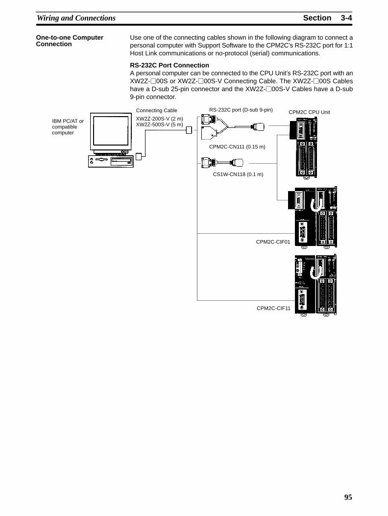
3-4SectionWiring and Connections
95
Use one of the connecting cables shown in the following diagram to connect apersonal computer with Support Software to the CPM2C’s RS-232C port for 1:1Host Link communications or no-protocol (serial) communications.
RS-232C Port ConnectionA personal computer can be connected to the CPU Unit’s RS-232C port with anXW2Z-00S or XW2Z-00S-V Connecting Cable. The XW2Z-00S Cableshave a D-sub 25-pin connector and the XW2Z-00S-V Cables have a D-sub9-pin connector.
RS-232C port (D-sub 9-pin) CPM2C CPU Unit
CPM2C-CN111 (0.15 m)
Connecting Cable
XW2Z-200S-V (2 m)XW2Z-500S-V (5 m)
CS1W-CN118 (0.1 m)
IBM PC/AT orcompatiblecomputer
CPM2C-CIF01
CPM2C-CIF11
One-to-one ComputerConnection
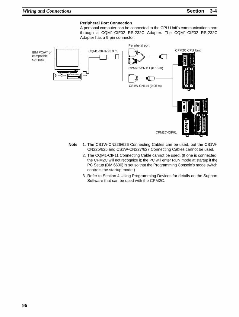
3-4SectionWiring and Connections
96
Peripheral Port ConnectionA personal computer can be connected to the CPU Unit’s communications portthrough a CQM1-CIF02 RS-232C Adapter. The CQM1-CIF02 RS-232CAdapter has a 9-pin connector.
Peripheral port
CPM2C CPU Unit
CPM2C-CN111 (0.15 m)
CS1W-CN114 (0.05 m)
CQM1-CIF02 (3.3 m)IBM PC/AT orcompatiblecomputer
CPM2C-CIF01
Note 1. The CS1W-CN226/626 Connecting Cables can be used, but the CS1W-CN225/625 and CS1W-CN227/627 Connecting Cables cannot be used.
2. The CQM1-CIF11 Connecting Cable cannot be used. (If one is connected,the CPM2C will not recognize it; the PC will enter RUN mode at startup if thePC Setup (DM 6600) is set so that the Programming Console’s mode switchcontrols the startup mode.)
3. Refer to Section 4 Using Programming Devices for details on the SupportSoftware that can be used with the CPM2C.
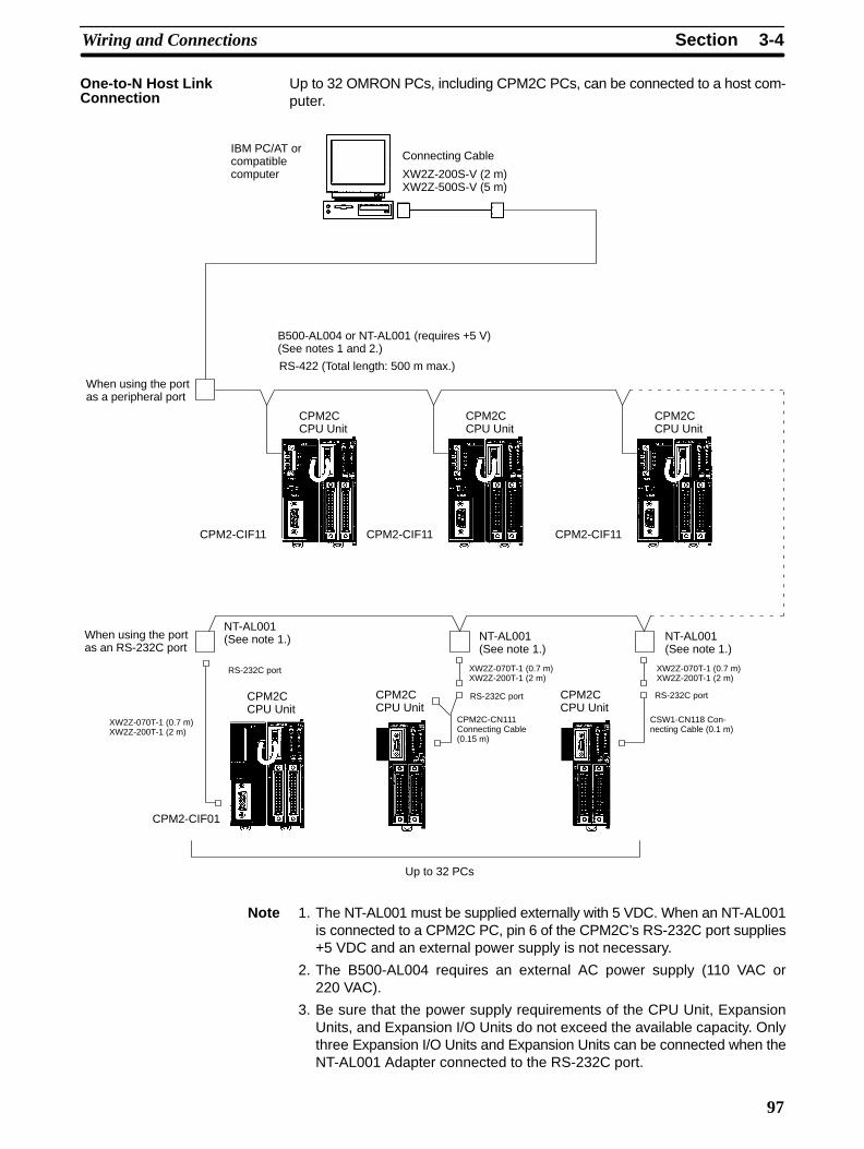
3-4SectionWiring and Connections
97
Up to 32 OMRON PCs, including CPM2C PCs, can be connected to a host com-puter.
Connecting Cable
XW2Z-200S-V (2 m)XW2Z-500S-V (5 m)
IBM PC/AT orcompatiblecomputer
B500-AL004 or NT-AL001 (requires +5 V)(See notes 1 and 2.)
RS-422 (Total length: 500 m max.)
When using the portas a peripheral port
CPM2CCPU Unit
CPM2CCPU Unit
CPM2CCPU Unit
CPM2-CIF11
When using the portas an RS-232C port
NT-AL001(See note 1.) NT-AL001
(See note 1.)NT-AL001(See note 1.)
RS-232C port
XW2Z-070T-1 (0.7 m)XW2Z-200T-1 (2 m)
CPM2-CIF01
XW2Z-070T-1 (0.7 m)XW2Z-200T-1 (2 m)
RS-232C port
CPM2C-CN111Connecting Cable(0.15 m)
Up to 32 PCs
XW2Z-070T-1 (0.7 m)XW2Z-200T-1 (2 m)
RS-232C port
CSW1-CN118 Con-necting Cable (0.1 m)
CPM2CCPU Unit
CPM2-CIF11
CPM2CCPU Unit
CPM2-CIF11
CPM2CCPU Unit
Note 1. The NT-AL001 must be supplied externally with 5 VDC. When an NT-AL001is connected to a CPM2C PC, pin 6 of the CPM2C’s RS-232C port supplies+5 VDC and an external power supply is not necessary.
2. The B500-AL004 requires an external AC power supply (110 VAC or220 VAC).
3. Be sure that the power supply requirements of the CPU Unit, ExpansionUnits, and Expansion I/O Units do not exceed the available capacity. Onlythree Expansion I/O Units and Expansion Units can be connected when theNT-AL001 Adapter connected to the RS-232C port.
One-to-N Host LinkConnection

3-4SectionWiring and Connections
98
3-4-11 No-Protocol CommunicationsThe TXD(48) and RXD(47) instructions can be used in no-protocol mode to ex-change data with standard serial devices. For example, data can be receivedfrom a bar code reader or transmitted to a serial printer. The serial devices canbe connected to the communications port as a RS-232C port or peripheral port,as shown in the following diagrams.
CPM2C CPU Unit
RS-232C devices
Bar code reader Serial printer Other serial device
Note See One-to-one Computer Connections on page 94 for details on the systemconfigurations that can be assembled for serial communications.

3-4SectionWiring and Connections
99
3-4-12 OMRON PT ConnectionsIn a 1:1 NT Link, a CPM2C can be connected directly to a Programmable Termi-nal. The direct connection with a Programmable Terminal is possible by usingthe communications as a RS-232C port only (not as a peripheral port).
A Programmable Terminal can also be connected by a Host Link connection. Ei-ther the RS-232C port or peripheral port connection can be used for the HostLink.
Connecting Cable
XW2Z-200T (2 m)XW2Z-500T (5 m)
NT-AL001RS-232C Adapter
CPM2C-CN111 (0.15 m)
XW2Z-070T-1 (0.7 m)XW2Z-200T-1 (2 m)
CS1W-CN118 (0.1 m)
CPM2C CPU Unit
OMRON ProgrammableTerminal
RS-232C port(D-sub 9-pin)
RS-232Cport
RS-232C ← peripheral port
RS-232C port
CPM2C-CIF01
RS-422 ← peripheral port
RS-232C port
CPM2C-CIF11
RS-232C connection
RS-422 connection
Note The Programmable Terminal cannot be connected using a peripheral port con-nection when communicating via an NT Link.
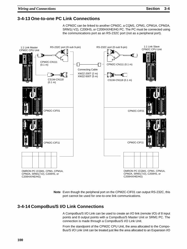
3-4SectionWiring and Connections
100
3-4-13 One-to-one PC Link Connections
A CPM2C can be linked to another CPM2C, a CQM1, CPM1, CPM1A, CPM2A,SRM1(-V2), C200HS, or C200HX/HE/HG PC. The PC must be connected usingthe communications port as an RS-232C port (not as a peripheral port).
CPM2C-CN111(0.1 m)
CS1W-CN118(0.1 m)
CS1W-CN118 (0.1 m)
1:1 Link MasterCPM2C CPU Unit
Connecting Cable
XW2Z-200T (2 m)XW2Z-500T (5 m)
RS-232C port (D-sub 9-pin)
CPM2C-CN111 (0.1 m)
RS-232C port (D-sub 9-pin) 1:1 Link SlaveCPM2C CPU Unit
OMRON PC (CQM1, CPM1, CPM1A,CPM2A, SRM1(-V2), C200HS, orC200HX/HE/HG)
OMRON PC (CQM1, CPM1, CPM1A,CPM2A, SRM1(-V2), C200HS, orC200HX/HE/HG)
CPM2C-CIF01
CPM2C-CIF11
CPM2C-CIF01
CPM2C-CIF11
Note Even though the peripheral port on the CPM2C-CIF01 can output RS-232C, thisport cannot be used for one-to-one link communications.
3-4-14 CompoBus/S I/O Link Connections
A CompoBus/S I/O Link can be used to create an I/O link (remote I/O) of 8 inputpoints and 8 output points with a CompoBus/S Master Unit or SRM1 PC. Theconnection is made through a CompoBus/S I/O Link Unit.
From the standpoint of the CPM2C CPU Unit, the area allocated to the Compo-Bus/S I/O Link Unit can be treated just like the area allocated to an Expansion I/O
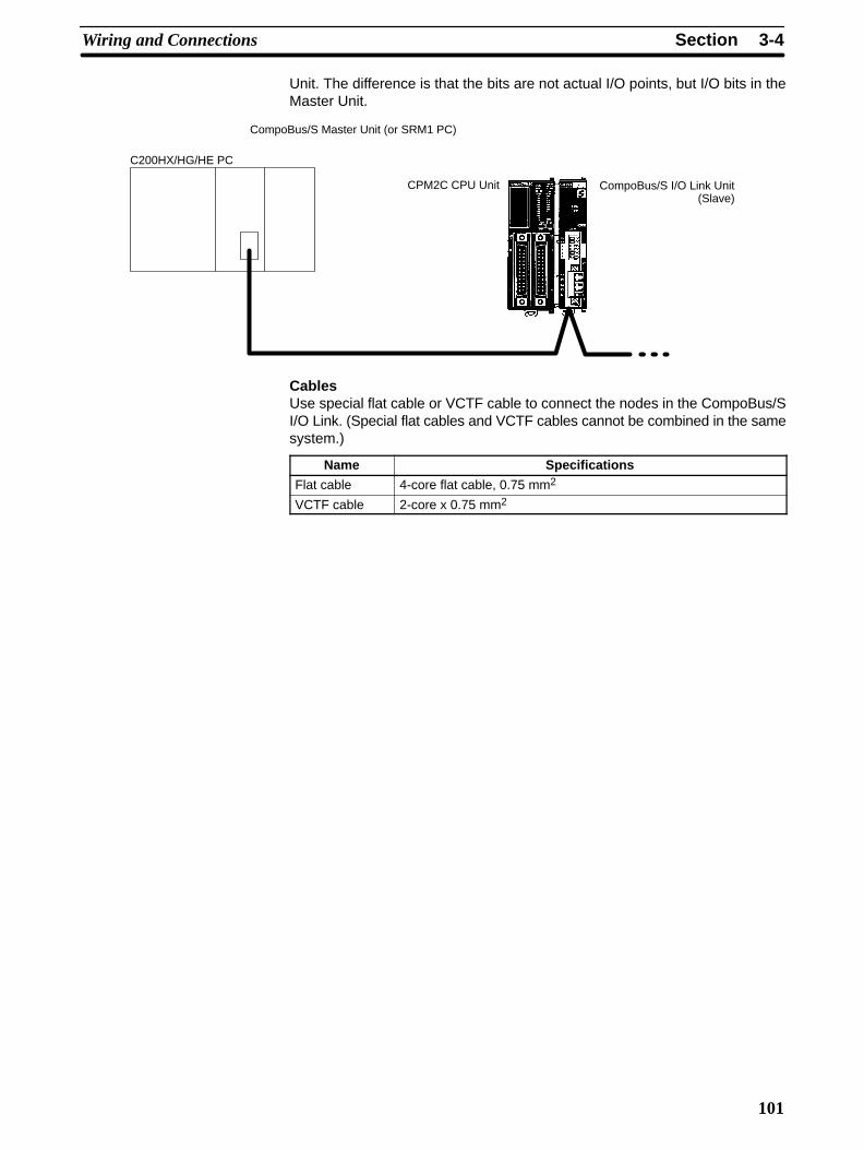
3-4SectionWiring and Connections
101
Unit. The difference is that the bits are not actual I/O points, but I/O bits in theMaster Unit.
CPM2C CPU Unit
CompoBus/S Master Unit (or SRM1 PC)
C200HX/HG/HE PC
CompoBus/S I/O Link Unit(Slave)
CablesUse special flat cable or VCTF cable to connect the nodes in the CompoBus/SI/O Link. (Special flat cables and VCTF cables cannot be combined in the samesystem.)
Name Specifications
Flat cable 4-core flat cable, 0.75 mm2
VCTF cable 2-core x 0.75 mm2
103
SECTION 4Using Programming Devices
This section outlines the operations possible with the SYSMAC-CPT, SYSMAC Support Software (SSS) and the Program-ming Consoles. Actual CPT operating procedures are provided in the CPT User Manual. Actual SSS operating procedures areprovided in the SSS Operation Manuals: Basics and C-series PCs. Operations for the WS02-CXPC1-E CX-Programmer areprovided in the WS02-CXPC1-E CX-Programmer User Manual (W361) and the CX-Server User Manual (W362).
Refer to 3-4-10 Programming Device Connections and 4-3-1 Connecting the Programming Console for details on connectinga Programming Console or personal computer to the CPM2C.
4-1 SYSMAC-CPT Support Software 104. . . . . . . . . . . . . . . . . . . . . . . . . . . . . . . . . . . . . . . . . . . . 4-1-1 Introduction 104. . . . . . . . . . . . . . . . . . . . . . . . . . . . . . . . . . . . . . . . . . . . . . . . . . . . . . 4-1-2 Limitations and Precautions 104. . . . . . . . . . . . . . . . . . . . . . . . . . . . . . . . . . . . . . . . . 4-1-3 Using the SYSMAC-CPT Support Software 106. . . . . . . . . . . . . . . . . . . . . . . . . . . . .
4-2 SYSMAC Support Software (SSS) 111. . . . . . . . . . . . . . . . . . . . . . . . . . . . . . . . . . . . . . . . . . . 4-2-1 Introduction 111. . . . . . . . . . . . . . . . . . . . . . . . . . . . . . . . . . . . . . . . . . . . . . . . . . . . . . 4-2-2 Limitations and Precautions 112. . . . . . . . . . . . . . . . . . . . . . . . . . . . . . . . . . . . . . . . .
4-3 Using a Programming Console 114. . . . . . . . . . . . . . . . . . . . . . . . . . . . . . . . . . . . . . . . . . . . . . 4-3-1 Connecting the Programming Console 114. . . . . . . . . . . . . . . . . . . . . . . . . . . . . . . . . 4-3-2 Compatible Programming Consoles 116. . . . . . . . . . . . . . . . . . . . . . . . . . . . . . . . . . . 4-3-3 Changing the CPM2C’s Mode with the Mode Switch 118. . . . . . . . . . . . . . . . . . . . . 4-3-4 Preparation for Operation 120. . . . . . . . . . . . . . . . . . . . . . . . . . . . . . . . . . . . . . . . . . . 4-3-5 Entering the Password 120. . . . . . . . . . . . . . . . . . . . . . . . . . . . . . . . . . . . . . . . . . . . . .
4-4 Programming Console Operations 122. . . . . . . . . . . . . . . . . . . . . . . . . . . . . . . . . . . . . . . . . . . . 4-4-1 Overview 122. . . . . . . . . . . . . . . . . . . . . . . . . . . . . . . . . . . . . . . . . . . . . . . . . . . . . . . . 4-4-2 Clearing Memory 123. . . . . . . . . . . . . . . . . . . . . . . . . . . . . . . . . . . . . . . . . . . . . . . . . . 4-4-3 Reading/Clearing Error Messages 124. . . . . . . . . . . . . . . . . . . . . . . . . . . . . . . . . . . . . 4-4-4 Buzzer Operation 124. . . . . . . . . . . . . . . . . . . . . . . . . . . . . . . . . . . . . . . . . . . . . . . . . . 4-4-5 Assigning Expansion Instruction Function Codes 125. . . . . . . . . . . . . . . . . . . . . . . . . 4-4-6 Setting and Reading a Program Memory Address and Monitoring I/O Bit Status 1264-4-7 Entering or Editing Programs 126. . . . . . . . . . . . . . . . . . . . . . . . . . . . . . . . . . . . . . . . 4-4-8 Instruction Search 129. . . . . . . . . . . . . . . . . . . . . . . . . . . . . . . . . . . . . . . . . . . . . . . . . 4-4-9 Bit Operand Search 130. . . . . . . . . . . . . . . . . . . . . . . . . . . . . . . . . . . . . . . . . . . . . . . . 4-4-10 Inserting and Deleting Instructions 131. . . . . . . . . . . . . . . . . . . . . . . . . . . . . . . . . . . . 4-4-11 Checking the Program 132. . . . . . . . . . . . . . . . . . . . . . . . . . . . . . . . . . . . . . . . . . . . . . 4-4-12 Bit, Digit, Word Monitor 132. . . . . . . . . . . . . . . . . . . . . . . . . . . . . . . . . . . . . . . . . . . . 4-4-13 Differentiation Monitor 134. . . . . . . . . . . . . . . . . . . . . . . . . . . . . . . . . . . . . . . . . . . . . 4-4-14 Binary Monitor 135. . . . . . . . . . . . . . . . . . . . . . . . . . . . . . . . . . . . . . . . . . . . . . . . . . . 4-4-15 Three-Word Monitor 136. . . . . . . . . . . . . . . . . . . . . . . . . . . . . . . . . . . . . . . . . . . . . . . 4-4-16 Signed Decimal Monitor 136. . . . . . . . . . . . . . . . . . . . . . . . . . . . . . . . . . . . . . . . . . . . 4-4-17 Unsigned Decimal Monitor 137. . . . . . . . . . . . . . . . . . . . . . . . . . . . . . . . . . . . . . . . . . 4-4-18 Three-Word Data Modification 137. . . . . . . . . . . . . . . . . . . . . . . . . . . . . . . . . . . . . . . 4-4-19 Changing Timer, Counter SV 138. . . . . . . . . . . . . . . . . . . . . . . . . . . . . . . . . . . . . . . . 4-4-20 Hexadecimal, BCD Data Modification 139. . . . . . . . . . . . . . . . . . . . . . . . . . . . . . . . . 4-4-21 Binary Data Modification 140. . . . . . . . . . . . . . . . . . . . . . . . . . . . . . . . . . . . . . . . . . . 4-4-22 Signed Decimal Data Modification 140. . . . . . . . . . . . . . . . . . . . . . . . . . . . . . . . . . . . 4-4-23 Unsigned Decimal Data Modification 141. . . . . . . . . . . . . . . . . . . . . . . . . . . . . . . . . . 4-4-24 Force Set, Reset 142. . . . . . . . . . . . . . . . . . . . . . . . . . . . . . . . . . . . . . . . . . . . . . . . . . . 4-4-25 Clear Force Set/Reset 143. . . . . . . . . . . . . . . . . . . . . . . . . . . . . . . . . . . . . . . . . . . . . . . 4-4-26 Hex-ASCII Display Change 143. . . . . . . . . . . . . . . . . . . . . . . . . . . . . . . . . . . . . . . . . 4-4-27 Displaying the Cycle Time 144. . . . . . . . . . . . . . . . . . . . . . . . . . . . . . . . . . . . . . . . . . 4-4-28 Reading and Setting the Clock 144. . . . . . . . . . . . . . . . . . . . . . . . . . . . . . . . . . . . . . . .
4-5 Programming Example 145. . . . . . . . . . . . . . . . . . . . . . . . . . . . . . . . . . . . . . . . . . . . . . . . . . . . . 4-5-1 Preparatory Operations 145. . . . . . . . . . . . . . . . . . . . . . . . . . . . . . . . . . . . . . . . . . . . . 4-5-2 Example Program 146. . . . . . . . . . . . . . . . . . . . . . . . . . . . . . . . . . . . . . . . . . . . . . . . . 4-5-3 Programming Procedures 147. . . . . . . . . . . . . . . . . . . . . . . . . . . . . . . . . . . . . . . . . . . . 4-5-4 Checking the Program 150. . . . . . . . . . . . . . . . . . . . . . . . . . . . . . . . . . . . . . . . . . . . . . 4-5-5 Test Run in MONITOR Mode 150. . . . . . . . . . . . . . . . . . . . . . . . . . . . . . . . . . . . . . . .

4-1SectionSYSMAC-CPT Support Software
104
4-1 SYSMAC-CPT Support Software
4-1-1 IntroductionThe SYSMAC-CPT Support Software is a complete programming and controlpackage. It provides not only programming capabilities, but also advanceddebugging, monitoring, and program/data management. The software is com-patible with Windows 3.1, Windows 95, Windows 98, and Windows NT 3.5/4.0.
Any version of the SYSMAC-CPT Support Software can be used to programCPM2C PCs with the limitations described later in this section. For furtherinformation and actual operating procedures, please refer to the SYSMAC-CPTSupport Software Quick Start Guide (W332) and User Manual (W333).
Refer to 3-4-10 Programming Device Connections for details on connecting apersonal computer to the CPM2C.
4-1-2 Limitations and PrecautionsWhen programming a CPM2C PC with the SYSMAC-CPT Support Software,set the PC model to “CQM1” and the CPU model to “CPU43.” There are somesoftware limitations because of differences between the CPM2C andCQM1-CPU43 CPUs.
CQM1 data areas are larger than the corresponding CPM2C data areas, so thedata area addresses that don’t actually exist in the CPM2C or instructions notsupported by the CPM2C can be input and won’t be detected in the programcheck. Be sure that the word and bit addresses are within the specified rangesand that all instructions are supported.
If a program contains a data area address that exceeds the range of a CPM2Cdata area, a memory error will be generated when the program is executed andthe Memory Area Specification Error Flag (AR 1308) will be turned ON.
Data area CQM1 range CPM2C range
Input words IR 000 to IR 011 IR 000 to IR 009
Output words IR 100 to IR 111 IR 010 to IR 019
Work words anddedicated words
IR 012 to IR 099IR 112 to IR 227
IR 020 to IR 049/IR 200 to IR 227(IR 050 to IR 199 cannot be used.)
SR area SR 228 to SR 255 SR 228 to SR 255
HR area HR 00 to HR 99 HR 00 to HR 19(HR 20 to HR 99 cannot be used.)
AR area AR 00 to AR 27 AR 00 to AR 23(AR 24 to AR 27 cannot be used.)
LR area LR 00 to LR 63 LR 00 to LR 15(LR 16 to LR 63 cannot be used.)
Timer/Counterarea
TIM/CNT 000 to 511 TIM/CNT 000 to 255(TIM/CNT 256 to 511 cannot be used.)
DMarea
Read/write DM 0000 to DM 6143 DM 0000 to DM 1999,DM 2022 to DM 2047(DM 2048 to DM 6143 cannot be used.)
Read-only DM 6144 to DM 6568 DM 6144 to DM 6599
Error Log DM 6569 to DM 6599 DM 2000 to DM 2021
PC Setup DM 6600 to DM 6655 DM 6600 to DM 6655
Since the PC model is set to “CQM1,” a program that will run properly in theCQM1 will pass the program check even if it won’t run properly in the CPM2C.
An error message will be displayed and the values will not be accepted if a dataarea address that exceeds the range of a CPM2C data area is entered for moni-toring, an instruction operand, or a timer/counter SV.
Program Input andProgram Check
Monitoring, OnlineEditing, and Set Values
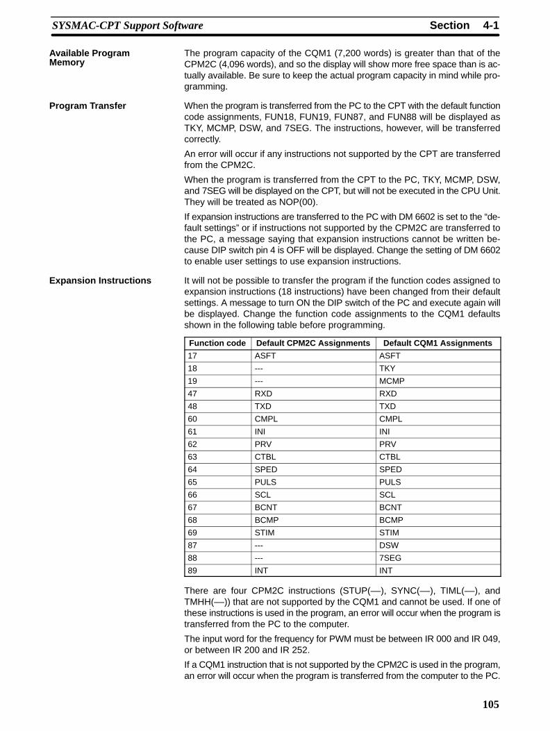
4-1SectionSYSMAC-CPT Support Software
105
The program capacity of the CQM1 (7,200 words) is greater than that of theCPM2C (4,096 words), and so the display will show more free space than is ac-tually available. Be sure to keep the actual program capacity in mind while pro-gramming.
When the program is transferred from the PC to the CPT with the default functioncode assignments, FUN18, FUN19, FUN87, and FUN88 will be displayed asTKY, MCMP, DSW, and 7SEG. The instructions, however, will be transferredcorrectly.
An error will occur if any instructions not supported by the CPT are transferredfrom the CPM2C.
When the program is transferred from the CPT to the PC, TKY, MCMP, DSW,and 7SEG will be displayed on the CPT, but will not be executed in the CPU Unit.They will be treated as NOP(00).
If expansion instructions are transferred to the PC with DM 6602 is set to the “de-fault settings” or if instructions not supported by the CPM2C are transferred tothe PC, a message saying that expansion instructions cannot be written be-cause DIP switch pin 4 is OFF will be displayed. Change the setting of DM 6602to enable user settings to use expansion instructions.
It will not be possible to transfer the program if the function codes assigned toexpansion instructions (18 instructions) have been changed from their defaultsettings. A message to turn ON the DIP switch of the PC and execute again willbe displayed. Change the function code assignments to the CQM1 defaultsshown in the following table before programming.
Function code Default CPM2C Assignments Default CQM1 Assignments
17 ASFT ASFT
18 --- TKY
19 --- MCMP
47 RXD RXD
48 TXD TXD
60 CMPL CMPL
61 INI INI
62 PRV PRV
63 CTBL CTBL
64 SPED SPED
65 PULS PULS
66 SCL SCL
67 BCNT BCNT
68 BCMP BCMP
69 STIM STIM
87 --- DSW
88 --- 7SEG
89 INT INT
There are four CPM2C instructions (STUP(––), SYNC(––), TIML(––), andTMHH(––)) that are not supported by the CQM1 and cannot be used. If one ofthese instructions is used in the program, an error will occur when the program istransferred from the PC to the computer.
The input word for the frequency for PWM must be between IR 000 and IR 049,or between IR 200 and IR 252.
If a CQM1 instruction that is not supported by the CPM2C is used in the program,an error will occur when the program is transferred from the computer to the PC.
Available ProgramMemory
Program Transfer
Expansion Instructions
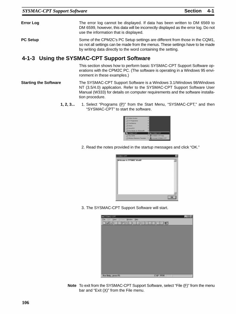
4-1SectionSYSMAC-CPT Support Software
106
The error log cannot be displayed. If data has been written to DM 6569 toDM 6599, however, this data will be incorrectly displayed as the error log. Do notuse the information that is displayed.
Some of the CPM2C’s PC Setup settings are different from those in the CQM1,so not all settings can be made from the menus. These settings have to be madeby writing data directly to the word containing the setting.
4-1-3 Using the SYSMAC-CPT Support SoftwareThis section shows how to perform basic SYSMAC-CPT Support Software op-erations with the CPM2C PC. (The software is operating in a Windows 95 envi-ronment in these examples.)
The SYSMAC-CPT Support Software is a Windows 3.1/Windows 98/WindowsNT (3.5/4.0) application. Refer to the SYSMAC-CPT Support Software UserManual (W333) for details on computer requirements and the software installa-tion procedure.
1, 2, 3... 1. Select “Programs (P)” from the Start Menu, “SYSMAC-CPT,” and then“SYSMAC-CPT” to start the software.
2. Read the notes provided in the startup messages and click “OK.”
3. The SYSMAC-CPT Support Software will start.
Note To exit from the SYSMAC-CPT Support Software, select “File (F)” from the menubar and “Exit (X)” from the File menu.
Error Log
PC Setup
Starting the Software

4-1SectionSYSMAC-CPT Support Software
107
Follow this procedure when using SYSMAC-CPT Support Software for the firsttime or creating a new project. Specify the PC model and CPU version of the PCbeing used.
1, 2, 3... 1. Select “File (F)” from the menu bar and “New (N)” from the File menu.
2. Input the name of the new project, set the PC model to “CQM1,” set the CPUversion to “CPU43,” and click “OK.”
a) Input theproject name.
b) Set the PC model to CQM1. c) Set the PC model to CQM1.
d) Click OK.
3. The new project’s ladder diagram will be displayed.
Creating a New Project
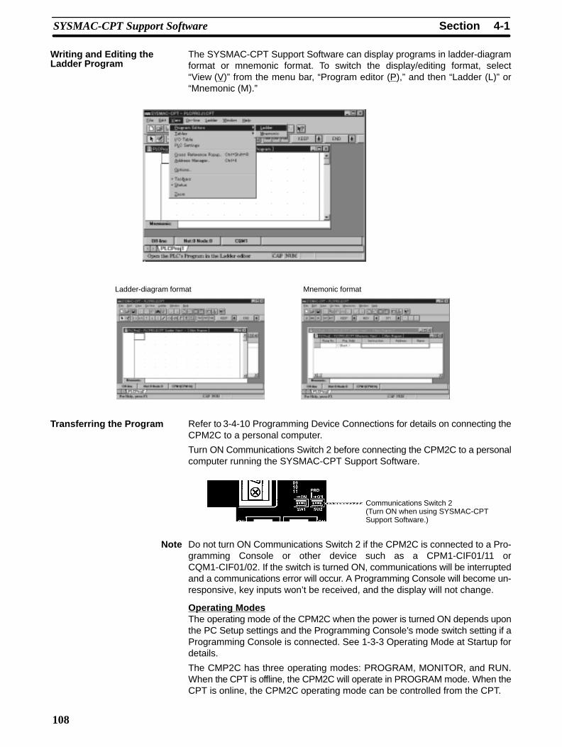
4-1SectionSYSMAC-CPT Support Software
108
The SYSMAC-CPT Support Software can display programs in ladder-diagramformat or mnemonic format. To switch the display/editing format, select“View (V)” from the menu bar, “Program editor (P),” and then “Ladder (L)” or“Mnemonic (M).”
Ladder-diagram format Mnemonic format
Refer to 3-4-10 Programming Device Connections for details on connecting theCPM2C to a personal computer.
Turn ON Communications Switch 2 before connecting the CPM2C to a personalcomputer running the SYSMAC-CPT Support Software.
Communications Switch 2(Turn ON when using SYSMAC-CPTSupport Software.)
Note Do not turn ON Communications Switch 2 if the CPM2C is connected to a Pro-gramming Console or other device such as a CPM1-CIF01/11 orCQM1-CIF01/02. If the switch is turned ON, communications will be interruptedand a communications error will occur. A Programming Console will become un-responsive, key inputs won’t be received, and the display will not change.
Operating ModesThe operating mode of the CPM2C when the power is turned ON depends uponthe PC Setup settings and the Programming Console’s mode switch setting if aProgramming Console is connected. See 1-3-3 Operating Mode at Startup fordetails.
The CMP2C has three operating modes: PROGRAM, MONITOR, and RUN.When the CPT is offline, the CPM2C will operate in PROGRAM mode. When theCPT is online, the CPM2C operating mode can be controlled from the CPT.
Writing and Editing theLadder Program
Transferring the Program
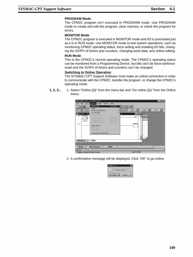
4-1SectionSYSMAC-CPT Support Software
109
PROGRAM ModeThe CPM2C program isn’t executed in PROGRAM mode. Use PROGRAMmode to create and edit the program, clear memory, or check the program forerrors.
MONITOR ModeThe CPM2C program is executed in MONITOR mode and I/O is processed justas it is in RUN mode. Use MONITOR mode to test system operations, such asmonitoring CPM2C operating status, force-setting and resetting I/O bits, chang-ing the SV/PV of timers and counters, changing word data, and online editing.
RUN ModeThis is the CPM2C’s normal operating mode. The CPM2C’s operating statuscan be monitored from a Programming Device, but bits can’t be force-set/force-reset and the SV/PV of timers and counters can’t be changed.
Switching to Online OperationThe SYSMAC-CPT Support Software must make an online connection in orderto communicate with the CPM2C, transfer the program, or change the CPM2C’soperating mode.
1, 2, 3... 1. Select “Online (O)” from the menu bar and “Go online (G)” from the Onlinemenu.
2. A confirmation message will be displayed. Click “OK” to go online.
Cancel
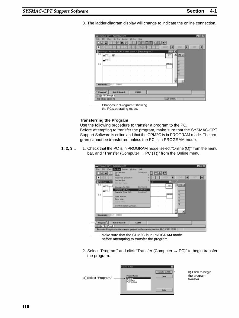
4-1SectionSYSMAC-CPT Support Software
110
3. The ladder-diagram display will change to indicate the online connection.
Changes to “Program,” showingthe PC’s operating mode.
Transferring the ProgramUse the following procedure to transfer a program to the PC.Before attempting to transfer the program, make sure that the SYSMAC-CPTSupport Software is online and that the CPM2C is in PROGRAM mode. The pro-gram cannot be transferred unless the PC is in PROGRAM mode.
1, 2, 3... 1. Check that the PC is in PROGRAM mode, select “Online (O)” from the menubar, and “Transfer (Computer → PC (T))” from the Online menu.
Make sure that the CPM2C is in PROGRAM modebefore attempting to transfer the program.
2. Select “Program” and click “Transfer (Computer → PC)” to begin transferthe program.
a) Select “Program.”
b) Click to beginthe programtransfer.
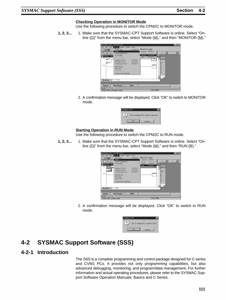
4-2SectionSYSMAC Support Software (SSS)
111
Checking Operation in MONITOR ModeUse the following procedure to switch the CPM2C to MONITOR mode.
1, 2, 3... 1. Make sure that the SYSMAC-CPT Support Software is online. Select “On-line (O)” from the menu bar, select “Mode (M),” and then “MONITOR (M).”
2. A confirmation message will be displayed. Click “OK” to switch to MONITORmode.
Cancel
Starting Operation in RUN ModeUse the following procedure to switch the CPM2C to RUN mode.
1, 2, 3... 1. Make sure that the SYSMAC-CPT Support Software is online. Select “On-line (O)” from the menu bar, select “Mode (M),” and then “RUN (R).”
2. A confirmation message will be displayed. Click “OK” to switch to RUNmode.
Cancel
4-2 SYSMAC Support Software (SSS)
4-2-1 IntroductionThe SSS is a complete programming and control package designed for C-seriesand CVM1 PCs. It provides not only programming capabilities, but alsoadvanced debugging, monitoring, and program/data management. For furtherinformation and actual operating procedures, please refer to the SYSMAC Sup-port Software Operation Manuals: Basics and C Series.
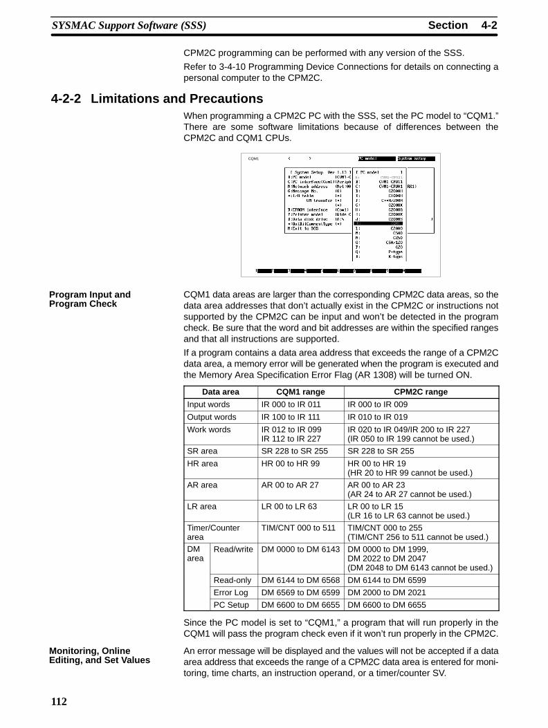
4-2SectionSYSMAC Support Software (SSS)
112
CPM2C programming can be performed with any version of the SSS.
Refer to 3-4-10 Programming Device Connections for details on connecting apersonal computer to the CPM2C.
4-2-2 Limitations and PrecautionsWhen programming a CPM2C PC with the SSS, set the PC model to “CQM1.”There are some software limitations because of differences between theCPM2C and CQM1 CPUs.
CQM1
A: CVM1-CPU21
K: CQM1
CQM1 data areas are larger than the corresponding CPM2C data areas, so thedata area addresses that don’t actually exist in the CPM2C or instructions notsupported by the CPM2C can be input and won’t be detected in the programcheck. Be sure that the word and bit addresses are within the specified rangesand that all instructions are supported.
If a program contains a data area address that exceeds the range of a CPM2Cdata area, a memory error will be generated when the program is executed andthe Memory Area Specification Error Flag (AR 1308) will be turned ON.
Data area CQM1 range CPM2C range
Input words IR 000 to IR 011 IR 000 to IR 009
Output words IR 100 to IR 111 IR 010 to IR 019
Work words IR 012 to IR 099IR 112 to IR 227
IR 020 to IR 049/IR 200 to IR 227(IR 050 to IR 199 cannot be used.)
SR area SR 228 to SR 255 SR 228 to SR 255
HR area HR 00 to HR 99 HR 00 to HR 19(HR 20 to HR 99 cannot be used.)
AR area AR 00 to AR 27 AR 00 to AR 23(AR 24 to AR 27 cannot be used.)
LR area LR 00 to LR 63 LR 00 to LR 15(LR 16 to LR 63 cannot be used.)
Timer/Counterarea
TIM/CNT 000 to 511 TIM/CNT 000 to 255(TIM/CNT 256 to 511 cannot be used.)
DMarea
Read/write DM 0000 to DM 6143 DM 0000 to DM 1999,DM 2022 to DM 2047(DM 2048 to DM 6143 cannot be used.)
Read-only DM 6144 to DM 6568 DM 6144 to DM 6599
Error Log DM 6569 to DM 6599 DM 2000 to DM 2021
PC Setup DM 6600 to DM 6655 DM 6600 to DM 6655
Since the PC model is set to “CQM1,” a program that will run properly in theCQM1 will pass the program check even if it won’t run properly in the CPM2C.
An error message will be displayed and the values will not be accepted if a dataarea address that exceeds the range of a CPM2C data area is entered for moni-toring, time charts, an instruction operand, or a timer/counter SV.
Program Input andProgram Check
Monitoring, OnlineEditing, and Set Values

4-2SectionSYSMAC Support Software (SSS)
113
DM Area addresses not supported by the CPM2C cannot be transferred or mon-itored. DM 1024 to DM 6143 are not checked for DM Area verification.
Since the program capacity of the CQM1 (7,200 words) is greater than that of theCPM2C (4,096 words), the display will show more free space than is actuallyavailable. Be sure to keep the actual program capacity in mind while program-ming.
When the program is transferred from the PC to the SSS with the default functioncode assignments, FUN18, FUN19, FUN87, and FUN88 will be displayed asTKY, MCMP, DSW, and 7SEG. The instructions, however, will be transferredcorrectly.“???” will be displayed if any instructions not supported by the SSS are trans-ferred from the CPM2C. Mnemonics will be displayed, however, if any havebeen defined for the specified function code.When the program is transferred from the SSS to the PC, TKY, MCMP, DSW,and 7SEG will be displayed on the SSS, but will not be executed in the CPU Unit.They will be treated as NOP.If expansion instructions are transferred to the PC with DM 6602 is set to the “de-fault settings,” a message saying that expansion instructions cannot be writtenbecause DIP switch pin 4 is OFF will be displayed. Change the setting ofDM 6602 to enable user settings to use expansion instructions. If instructionsnot supported by the CPM2C are transferred to the PC, a message saying to setexpansion instructions will be displayed, and transfer will not be possible.
It will not be possible to transfer the program if the function codes assigned toexpansion instructions have been changed from their default settings. A mes-sage to turn ON the DIP switch of the PC and execute again will be displayed.Change the function code assignments to the CQM1 defaults shown in the fol-lowing table before programming.
Function code Default CPM2C Assignments Default CQM1 Assignments
17 ASFT ASFT
18 --- TKY
19 --- MCMP
47 RXD RXD
48 TXD TXD
60 CMPL CMPL
61 INI INI
62 PRV PRV
63 CTBL CTBL
64 SPED SPED
65 PULS PULS
66 SCL SCL
67 BCNT BCNT
68 BCMP BCMP
69 STIM STIM
87 --- DSW
88 --- 7SEG
89 INT INT
If a CQM1 instruction that is not supported by the CPM2C is used in the program,an error will occur when the program is transferred from the computer to the PC.There are four CPM2C instructions (STUP(––), SYNC(––), TIML(––), andTMHH(––)) that are not supported by the CQM1. These instructions can be usedby transferring the expansion instructions from the CPM2C to the SSS. This pro-cedure is outlined in the following.
Transferring andVerifying DM Area Data
Available ProgramMemory
Program Transfer
Expansion Instructions

4-3SectionUsing a Programming Console
114
1, 2, 3... 1. Select “Transfer Instr” from the “Utility” menu.2. Confirm the transfer by pressing “Y” when the confirmation pop-up is dis-
played.
3. The “Utility” menu will be displayed again when the transfer is completed.
Since some of the CPM2C’s PC Setup settings are different from those in theCQM1, not all settings can be made from the menus. These settings have to bemade by writing data directly to the word containing the setting.
4-3 Using a Programming ConsoleThis section provides information on connecting and using a Programming Con-sole. Refer to 5-3 Programming Console Operation Errors for details on errorsthat might occur during Programming Console operations.
4-3-1 Connecting the Programming ConsoleA Programming Console can be connected to the CPM2C’s communicationsport or the peripheral port on a CPM2C-CN111 Connecting Cable; it cannot beconnected to the CPM2C-CN111 Connecting Cable’s RS-232C port.Before connecting the Programming Console, turn OFF CommunicationsSwitch 2 on the front of the CPM2C CPU Unit. The green “PRO” indicator on theCPU Unit will light.
Communications Switch 2
Note 1. When Communications Switch 2 is OFF, the Programming Console func-tions of an OMRON PT connected to the RS-232C port cannot be used.Turn ON Communications Switch 2 to use the PT’s Programming Consolefunctions.
2. Do not change the setting of Communications Switch 2 if a ProgrammingConsole or other device such as a CPM1-CIF01/11 or CQM1-CIF01/02 isconnected. Changing the setting will interrupt communications and cause acommunications error. If a Programming Console is connected, it will be-come unresponsive, key inputs won’t be received, and the display will notchange.
3. If the Programming Console’s cable is disconnected and then reconnectedwithin 2 seconds, it won’t be necessary to reenter the password and the pre-vious display status will remain. In some cases, it won’t be necessary to re-enter the password if the Programming Console’s cable is disconnectedwhile a time-consuming operation (such as a program check) is being per-formed.
PC Setup
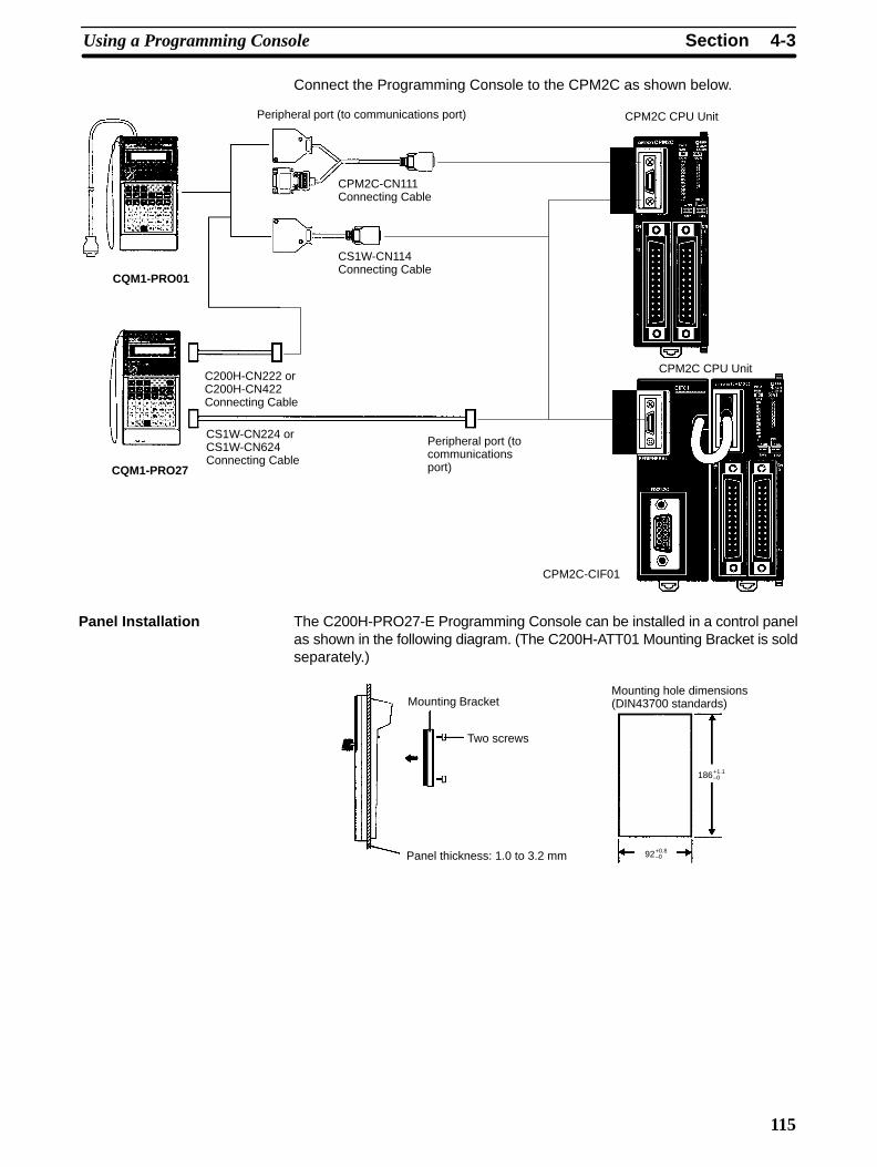
4-3SectionUsing a Programming Console
115
Connect the Programming Console to the CPM2C as shown below.
Peripheral port (to communications port) CPM2C CPU Unit
CPM2C-CN111Connecting Cable
CS1W-CN114Connecting Cable
CQM1-PRO01
CS1W-CN224 orCS1W-CN624Connecting Cable
CPM2C CPU Unit
CQM1-PRO27
CPM2C-CIF01
C200H-CN222 orC200H-CN422Connecting Cable
Peripheral port (tocommunicationsport)
The C200H-PRO27-E Programming Console can be installed in a control panelas shown in the following diagram. (The C200H-ATT01 Mounting Bracket is soldseparately.)
186+1.1–0
92+0.8–0
Mounting Bracket
Two screws
Panel thickness: 1.0 to 3.2 mm
Mounting hole dimensions(DIN43700 standards)
Panel Installation
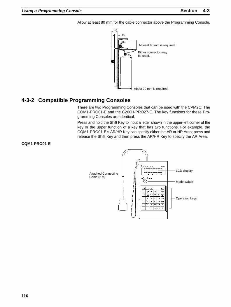
4-3SectionUsing a Programming Console
116
Allow at least 80 mm for the cable connector above the Programming Console.
About 70 mm is required.
At least 80 mm is required.
Either connector maybe used.
37
15
4-3-2 Compatible Programming ConsolesThere are two Programming Consoles that can be used with the CPM2C: TheCQM1-PRO01-E and the C200H-PRO27-E. The key functions for these Pro-gramming Consoles are identical.
Press and hold the Shift Key to input a letter shown in the upper-left corner of thekey or the upper function of a key that has two functions. For example, theCQM1-PRO01-E’s AR/HR Key can specify either the AR or HR Area; press andrelease the Shift Key and then press the AR/HR Key to specify the AR Area.
CQM1-PRO01-E
LCD display
Mode switch
Operation keys
Attached ConnectingCable (2 m)
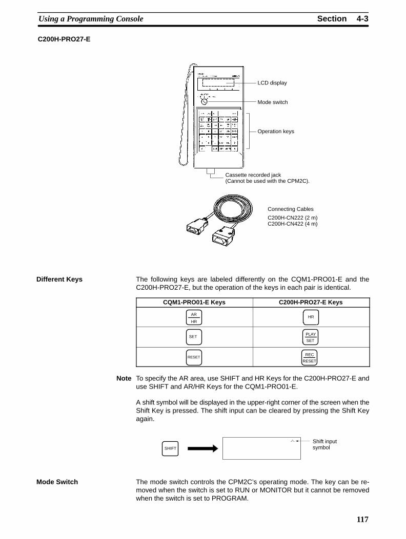
4-3SectionUsing a Programming Console
117
C200H-PRO27-E
Cassette recorded jack (Cannot be used with the CPM2C).
Connecting Cables
C200H-CN222 (2 m)C200H-CN422 (4 m)
LCD display
Mode switch
Operation keys
The following keys are labeled differently on the CQM1-PRO01-E and theC200H-PRO27-E, but the operation of the keys in each pair is identical.
CQM1-PRO01-E Keys C200H-PRO27-E Keys
AR
HRHR
SETPLAY
SET
RESETREC
RESET
Note To specify the AR area, use SHIFT and HR Keys for the C200H-PRO27-E anduse SHIFT and AR/HR Keys for the CQM1-PRO01-E.
A shift symbol will be displayed in the upper-right corner of the screen when theShift Key is pressed. The shift input can be cleared by pressing the Shift Keyagain.
Shift inputsymbol
SHIFT
The mode switch controls the CPM2C’s operating mode. The key can be re-moved when the switch is set to RUN or MONITOR but it cannot be removedwhen the switch is set to PROGRAM.
Different Keys
Mode Switch
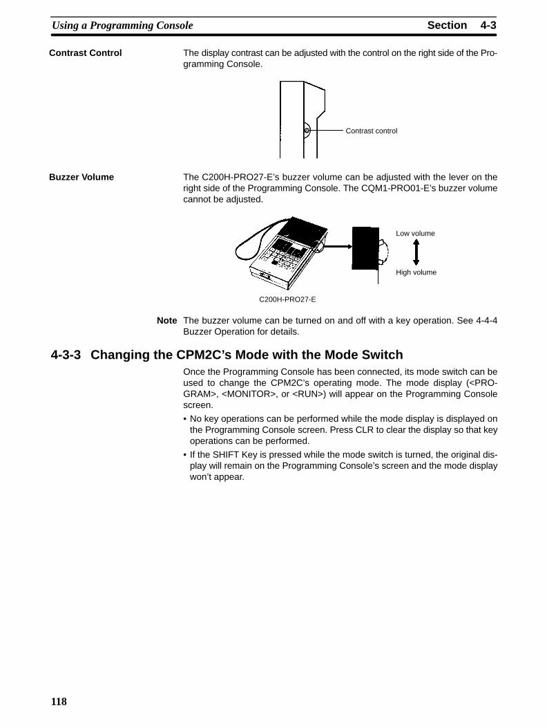
4-3SectionUsing a Programming Console
118
The display contrast can be adjusted with the control on the right side of the Pro-gramming Console.
Contrast control
The C200H-PRO27-E’s buzzer volume can be adjusted with the lever on theright side of the Programming Console. The CQM1-PRO01-E’s buzzer volumecannot be adjusted.
Low volume
High volume
C200H-PRO27-E
Note The buzzer volume can be turned on and off with a key operation. See 4-4-4Buzzer Operation for details.
4-3-3 Changing the CPM2C’s Mode with the Mode SwitchOnce the Programming Console has been connected, its mode switch can beused to change the CPM2C’s operating mode. The mode display (<PRO-GRAM>, <MONITOR>, or <RUN>) will appear on the Programming Consolescreen.
• No key operations can be performed while the mode display is displayed onthe Programming Console screen. Press CLR to clear the display so that keyoperations can be performed.
• If the SHIFT Key is pressed while the mode switch is turned, the original dis-play will remain on the Programming Console’s screen and the mode displaywon’t appear.
Contrast Control
Buzzer Volume

!
!
4-3SectionUsing a Programming Console
119
• The CPM2C will enter RUN mode automatically if a Programming Consoleisn’t connected when the CPM2C is turned on.
Mode display
Initial display
CLR SHIFT CLR
RUNMONITOR
PROGRAM RUNMONITOR
PROGRAMRUNMONITOR
PROGRAM
Operation Operation
Operating ModesPROGRAM ModeThe CPM2C program isn’t executed in PROGRAM mode. Use PROGRAMmode to create and edit the program, clear memory, or check the program forerrors.
MONITOR ModeThe CPM2C program is executed in MONITOR mode and I/O is processed justas it is in RUN mode. Use MONITOR mode to test system operations, such asmonitoring CPM2C operating status, force-setting and resetting I/O bits, chang-ing the SV/PV of timers and counters, changing word data, and online editing.
RUN ModeThis is the CPM2C’s normal operating mode. The CPM2C’s operating statuscan be monitored from a Programming Device, but bits can’t be force-set/force-reset and the SV/PV of timers and counters can’t be changed.
Caution Check the system thoroughly before changing the operating mode of the PC toprevent any accidents that might occur when the program is first started.
Caution Never change the mode while pressing any of the keys.
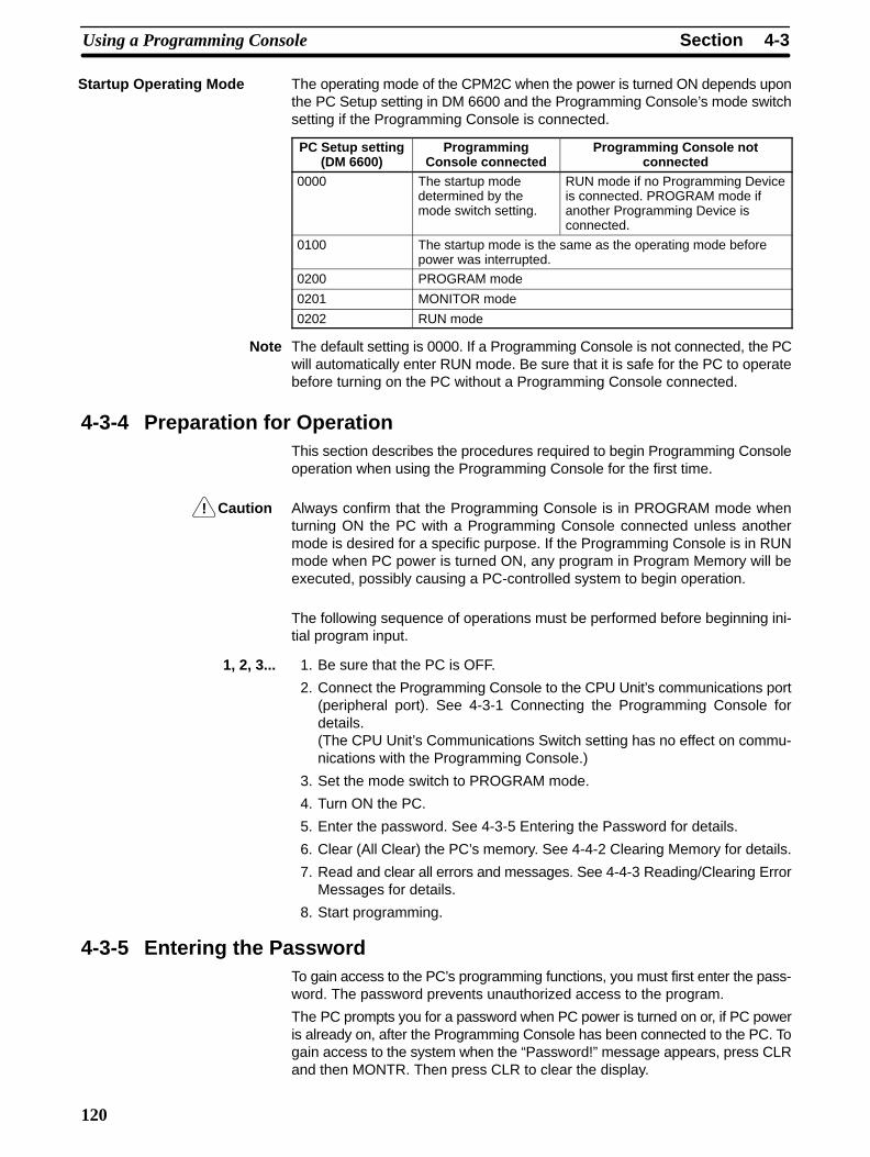
!
4-3SectionUsing a Programming Console
120
The operating mode of the CPM2C when the power is turned ON depends uponthe PC Setup setting in DM 6600 and the Programming Console’s mode switchsetting if the Programming Console is connected.
PC Setup setting(DM 6600)
ProgrammingConsole connected
Programming Console notconnected
0000 The startup modedetermined by themode switch setting.
RUN mode if no Programming Deviceis connected. PROGRAM mode ifanother Programming Device isconnected.
0100 The startup mode is the same as the operating mode beforepower was interrupted.
0200 PROGRAM mode
0201 MONITOR mode
0202 RUN mode
Note The default setting is 0000. If a Programming Console is not connected, the PCwill automatically enter RUN mode. Be sure that it is safe for the PC to operatebefore turning on the PC without a Programming Console connected.
4-3-4 Preparation for OperationThis section describes the procedures required to begin Programming Consoleoperation when using the Programming Console for the first time.
Caution Always confirm that the Programming Console is in PROGRAM mode whenturning ON the PC with a Programming Console connected unless anothermode is desired for a specific purpose. If the Programming Console is in RUNmode when PC power is turned ON, any program in Program Memory will beexecuted, possibly causing a PC-controlled system to begin operation.
The following sequence of operations must be performed before beginning ini-tial program input.
1, 2, 3... 1. Be sure that the PC is OFF.
2. Connect the Programming Console to the CPU Unit’s communications port(peripheral port). See 4-3-1 Connecting the Programming Console fordetails.(The CPU Unit’s Communications Switch setting has no effect on commu-nications with the Programming Console.)
3. Set the mode switch to PROGRAM mode.
4. Turn ON the PC.
5. Enter the password. See 4-3-5 Entering the Password for details.
6. Clear (All Clear) the PC’s memory. See 4-4-2 Clearing Memory for details.
7. Read and clear all errors and messages. See 4-4-3 Reading/Clearing ErrorMessages for details.
8. Start programming.
4-3-5 Entering the PasswordTo gain access to the PC’s programming functions, you must first enter the pass-word. The password prevents unauthorized access to the program.
The PC prompts you for a password when PC power is turned on or, if PC poweris already on, after the Programming Console has been connected to the PC. Togain access to the system when the “Password!” message appears, press CLRand then MONTR. Then press CLR to clear the display.
Startup Operating Mode

4-3SectionUsing a Programming Console
121
If the Programming Console is connected to the PC when PC power is alreadyon, the first display below will indicate the mode the PC was in before the Pro-gramming Console was connected. Ensure that the PC is in PROGRAM modebefore you enter the password. When the password is entered, the PC willshift to the mode set on the mode switch, causing PC operation to begin if themode is set to RUN or MONITOR. The mode can be changed to RUN or MON-ITOR with the mode switch after entering the password.
Indicates the mode set by the mode selector switch.

4-4SectionProgramming Console Operations
122
4-4 Programming Console Operations
4-4-1 Overview
The following table lists the programming and monitoring operations that can beperformed from a Programming Console. Refer to the rest of this section fordetails on operational procedures.
Name Function Page
Clearing memory Clears all or part of the Program Memory and any data areas that are notread-only, as well as the contents of the Programming Console’s memory.
123
Reading/clearing errormessages
Displays and clears error messages and displays MESSAGE instructionmessages.
124
Buzzer operation Turns on and off the buzzer that sounds when Programming Console keysare pressed.
124
Assigning expansioninstruction function codes
Reads or changes the function codes assigned to expansion instructions 125
Setting a program memoryaddress
Sets the specified program memory address when reading, writing,inserting and deleting programs.
126
Reading a program memoryaddress
Reads the contents of the Program Memory. Displays the status of thecurrently displayed bit in PROGRAM and MONITOR modes.
126
Instruction search Finds occurrences of the specified instruction in the program. 129
Bit operand search Finds occurrences of the specified operand bit in the program. 130
Inserting and deletinginstructions
Inserts or deletes instructions from the program. 131
Entering or editing programs Overwrites the contents of the current Program Memory to either input aprogram for the first time or to change a program that already exists.
126
Checking the program Checks for programming errors and displays the program address anderror when errors are found.
132
Bit, digit, word monitor Monitors the status of up to 16 bits and words, although only 3 can beshown on the display at one time.
132
Multiple address monitor Monitors the status of up to 6 bits and words simultaneously. 134
Differentiation monitor Monitors the up or down differentiation status of a particular bit. 134
Binary monitor Monitors the ON/OFF status of any word’s 16 bits. 135
3-word monitor Monitors the status of three consecutive words. 136
Signed decimal monitor Converts the contents of the specified word from signed hexadecimal(two’s complement format) to signed decimal for display.
136
Unsigned decimal monitor Converts hexadecimal data in a word to unsigned decimal for display. 137
3-word data modification Changes the contents of one or more of the 3 consecutive wordsdisplayed in the 3-Word Monitor operation.
137
Changing timer, counter SV 1 Changes the SV of a timer or counter. 138
Changing timer, counter SV 2 Makes fine adjustment changes to the SV of the timer or counter. 139
Hexadecimal, BCD datamodification
Changes the BCD or hexadecimal value of a word being monitored. 139
Binary data modification Changes the status of a word’s bits when the word is being monitored. 140
Signed decimal datamodification
Changes the decimal value of a word being monitored as signed decimaldata, within a range of –32,768 to 32,767. The contents of the specifiedword are converted automatically to signed hexadecimal (two’scomplement format.)
140
Unsigned decimal datamodification
Changes the decimal value of a word being monitored as unsigneddecimal data, within a range of 0 to 65,535. A change into hexadecimaldata is made automatically.
141
Force set/reset Forces bits ON (force set) or OFF (force reset.) 142
Clear force set/reset Restores the status of all bits which have been force set of reset. 143
Hex-ASCII display change Converts word data displays back and forth between 4-digit hexadecimaldata and ASCII.
143
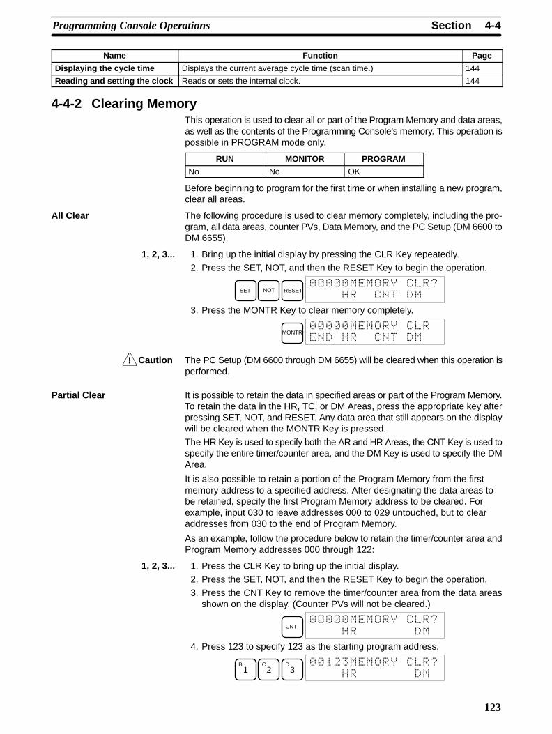
!
4-4SectionProgramming Console Operations
123
Name PageFunction
Displaying the cycle time Displays the current average cycle time (scan time.) 144
Reading and setting the clock Reads or sets the internal clock. 144
4-4-2 Clearing MemoryThis operation is used to clear all or part of the Program Memory and data areas,as well as the contents of the Programming Console’s memory. This operation ispossible in PROGRAM mode only.
RUN MONITOR PROGRAM
No No OK
Before beginning to program for the first time or when installing a new program,clear all areas.
All Clear The following procedure is used to clear memory completely, including the pro-gram, all data areas, counter PVs, Data Memory, and the PC Setup (DM 6600 toDM 6655).
1, 2, 3... 1. Bring up the initial display by pressing the CLR Key repeatedly.
2. Press the SET, NOT, and then the RESET Key to begin the operation.
SET NOT RESET
3. Press the MONTR Key to clear memory completely.
MONTR
Caution The PC Setup (DM 6600 through DM 6655) will be cleared when this operation isperformed.
Partial Clear It is possible to retain the data in specified areas or part of the Program Memory.To retain the data in the HR, TC, or DM Areas, press the appropriate key afterpressing SET, NOT, and RESET. Any data area that still appears on the displaywill be cleared when the MONTR Key is pressed.
The HR Key is used to specify both the AR and HR Areas, the CNT Key is used tospecify the entire timer/counter area, and the DM Key is used to specify the DMArea.
It is also possible to retain a portion of the Program Memory from the firstmemory address to a specified address. After designating the data areas tobe retained, specify the first Program Memory address to be cleared. Forexample, input 030 to leave addresses 000 to 029 untouched, but to clearaddresses from 030 to the end of Program Memory.
As an example, follow the procedure below to retain the timer/counter area andProgram Memory addresses 000 through 122:
1, 2, 3... 1. Press the CLR Key to bring up the initial display.
2. Press the SET, NOT, and then the RESET Key to begin the operation.
3. Press the CNT Key to remove the timer/counter area from the data areasshown on the display. (Counter PVs will not be cleared.)
CNT
4. Press 123 to specify 123 as the starting program address.
B1
C2
D3
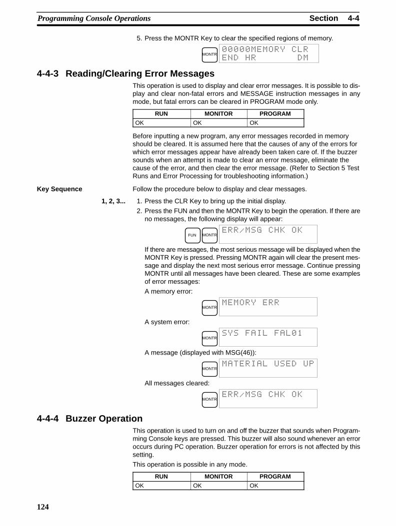
4-4SectionProgramming Console Operations
124
5. Press the MONTR Key to clear the specified regions of memory.
MONTR
4-4-3 Reading/Clearing Error MessagesThis operation is used to display and clear error messages. It is possible to dis-play and clear non-fatal errors and MESSAGE instruction messages in anymode, but fatal errors can be cleared in PROGRAM mode only.
RUN MONITOR PROGRAM
OK OK OK
Before inputting a new program, any error messages recorded in memoryshould be cleared. It is assumed here that the causes of any of the errors forwhich error messages appear have already been taken care of. If the buzzersounds when an attempt is made to clear an error message, eliminate thecause of the error, and then clear the error message. (Refer to Section 5 TestRuns and Error Processing for troubleshooting information.)
Key Sequence Follow the procedure below to display and clear messages.
1, 2, 3... 1. Press the CLR Key to bring up the initial display.
2. Press the FUN and then the MONTR Key to begin the operation. If there areno messages, the following display will appear:
FUN MONTR
If there are messages, the most serious message will be displayed when theMONTR Key is pressed. Pressing MONTR again will clear the present mes-sage and display the next most serious error message. Continue pressingMONTR until all messages have been cleared. These are some examplesof error messages:
A memory error:
MONTR
A system error:
MONTR!!
A message (displayed with MSG(46)):
MONTR
All messages cleared:
MONTR
4-4-4 Buzzer OperationThis operation is used to turn on and off the buzzer that sounds when Program-ming Console keys are pressed. This buzzer will also sound whenever an erroroccurs during PC operation. Buzzer operation for errors is not affected by thissetting.
This operation is possible in any mode.
RUN MONITOR PROGRAM
OK OK OK
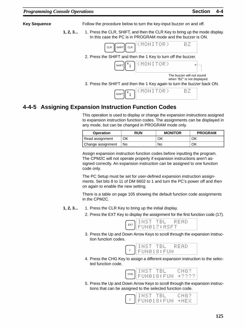
4-4SectionProgramming Console Operations
125
Key Sequence Follow the procedure below to turn the key-input buzzer on and off.
1, 2, 3... 1. Press the CLR, SHIFT, and then the CLR Key to bring up the mode display.In this case the PC is in PROGRAM mode and the buzzer is ON.
CLR SHIFT CLR
2. Press the SHIFT and then the 1 Key to turn off the buzzer.
SHIFTB
1
The buzzer will not soundwhen “BZ” is not displayed.
3. Press the SHIFT and then the 1 Key again to turn the buzzer back ON.
SHIFTB
1
4-4-5 Assigning Expansion Instruction Function CodesThis operation is used to display or change the expansion instructions assignedto expansion instruction function codes. The assignments can be displayed inany mode, but can be changed in PROGRAM mode only.
Operation RUN MONITOR PROGRAM
Read assignment OK OK OK
Change assignment No No OK
Assign expansion instruction function codes before inputting the program.The CPM2C will not operate properly if expansion instructions aren’t as-signed correctly. An expansion instruction can be assigned to one functioncode only.
The PC Setup must be set for user-defined expansion instruction assign-ments. Set bits 8 to 11 of DM 6602 to 1 and turn the PC’s power off and thenon again to enable the new setting.
There is a table on page 105 showing the default function code assignmentsin the CPM2C.
1, 2, 3... 1. Press the CLR Key to bring up the initial display.
2. Press the EXT Key to display the assignment for the first function code (17).
EXT
! "#!
3. Press the Up and Down Arrow Keys to scroll through the expansion instruc-tion function codes.
↓
! $#!
4. Press the CHG Key to assign a different expansion instruction to the selec-ted function code.
CHG
! $#!%
5. Press the Up and Down Arrow Keys to scroll through the expansion instruc-tions that can be assigned to the selected function code.
↓
! $#!%&

4-4SectionProgramming Console Operations
126
6. Press the WRITE Key to assign the displayed instruction to the functioncode.
WRITE
! $#&
4-4-6 Setting and Reading a Program Memory Address and MonitoringI/O Bit Status
This operation is used to display the specified program memory address and ispossible in any mode. In the RUN or MONITOR mode, the I/O bit status of bits inthe program will be displayed.
RUN MONITOR PROGRAM
OK OK OK
When inputting a program for the first time, it is generally written to ProgramMemory starting from address 000. Because this address appears when thedisplay is cleared, it is not necessary to specify it.
When inputting a program starting from other than 000 or to read or modify aprogram that already exists in memory, the desired address must be desig-nated.
1, 2, 3... 1. Press the CLR Key to bring up the initial display.
2. Input the desired address. It is not necessary to input leading zeroes.
C2
A0
A0
3. Press the Down Arrow Key.
↓ !!
In the RUN or MONITORmode, ON/OFF status ofthe bit will be displayed.
Pressing the MONTR Key will change to the I/O monitor display. Bits can beforce-set or force-reset from the I/O monitor display. Press the CLR Key toreturn to I/O bit status monitoring of the initial address.
Note The ON/OFF status of any displayed bit will be shown if the PC is inRUN or MONITOR mode.
4. Press the Up and Down Arrow Keys to scroll through the program.
↓
↑ !!
4-4-7 Entering or Editing ProgramsThis operation is used enter or edit programs. It is possible in PROGRAM modeonly.
RUN MONITOR PROGRAM
No No OK
The same procedure is used to either input a program for the first time or tochange a program that already exists. In either case, the current contents ofProgram Memory is overwritten.

4-4SectionProgramming Console Operations
127
The program shown in the following diagram will be entered to demonstratethis operation.
00002
00200 LD IR 00002
00201 TIM 000
#0123
00202 MOV(021)
#0100
LR 10
00203 ADB(050)
#0100
#FFF6
DM 0000
MOV(021)
#0100
LR 10
TIM 000
#0123 12.3 s
ADB(050)
#0100
#FFF6
DM 0000
Address Instruction Operands
1, 2, 3... 1. Press the CLR Key to bring up the initial display.
2. Specify the address where the program will begin.
3. Input the address where the program will begin and press the Down ArrowKey. It is not necessary to input leading zeroes.
C2
A0
A0 ↓
' (
4. Input the first instruction and operand.
LD C2
5. Press the WRITE Key to write the instruction to Program Memory. The nextprogram address will be displayed.
WRITE
' (
If a mistake was made inputting the instruction, press the Up Arrow Key toreturn to the previous program address and input the instruction again. Themistaken instruction will be overwritten
To specify the Completion Flag for a timer or counter, press the LD, AND,OR, or NOT Key followed by the TIM or CNT Key, and then input the timer/counter number last.
6. Input the second instruction and operand. (In this case it isn’t necessary toenter the timer number, because it’s 000.) Press the WRITE Key to write theinstruction to Program Memory.
TIM Timer number WRITE
)
7. Input the second operand (123 to specify 12.3 seconds) and press theWRITE Key. The next program address will be displayed.
B1
C2
D3 WRITE
' (
If a mistake was made inputting the operand, press the Up Arrow Key toreturn to display the mistaken operand and input the operand again.
Note a) Counters are input in the same basic way as timers except theCNT Key is pressed instead of the TIM Key.
b) Timer and counter SVs are input in BCD, so it isn’t necessary topress the CONT/# Key.
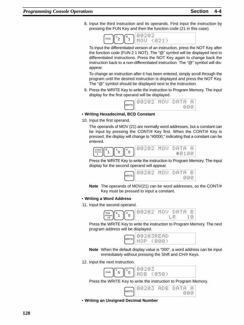
4-4SectionProgramming Console Operations
128
8. Input the third instruction and its operands. First input the instruction bypressing the FUN Key and then the function code (21 in this case).
FUNC
2B
1
*' (
To input the differentiated version of an instruction, press the NOT Key afterthe function code (FUN 2 1 NOT). The “@” symbol will be displayed next todifferentiated instructions. Press the NOT Key again to change back theinstruction back to a non-differentiated instruction. The “@” symbol will dis-appear.
To change an instruction after it has been entered, simply scroll through theprogram until the desired instruction is displayed and press the NOT Key.The “@” symbol should be displayed next to the instruction.
9. Press the WRITE Key to write the instruction to Program Memory. The inputdisplay for the first operand will be displayed.
WRITE *
• Writing Hexadecimal, BCD Constant
10. Input the first operand.
The operands of MOV (21) are normally word addresses, but a constant canbe input by pressing the CONT/# Key first. When the CONT/# Key ispressed, the display will change to “#0000,” indicating that a constant can beentered.
CONT
#
B1
A0
A0
*
)
Press the WRITE Key to write the instruction to Program Memory. The inputdisplay for the second operand will appear.
WRITE *
Note The operands of MOV(21) can be word addresses, so the CONT/#Key must be pressed to input a constant.
• Writing a Word Address
11. Input the second operand.
*EM
LR
B1
A0
*
Press the WRITE Key to write the instruction to Program Memory. The nextprogram address will be displayed.
WRITE
' (
Note When the default display value is “000”, a word address can be inputimmediately without pressing the Shift and CH/# Keys.
12. Input the next instruction.
FUNF
5A
0
' + (
Press the WRITE Key to write the instruction to Program Memory.
WRITE
• Writing an Unsigned Decimal Number

4-4SectionProgramming Console Operations
129
13. The first operand is input as an unsigned integer.
CONT
#SHIFT TR NOT
)
Input the value of the operand from 0 to 65535.
C2
F5 6
) +,
Note If an erroneous input is made, press the CLR Key to restore the statusprior to the input. Then enter the correct input.
14. Restore the hexadecimal display.
SHIFT TR
)
Note If an input is made outside of the permissible range, a buzzer willsound and the hexadecimal display will not be displayed.
WRITE
15. The second operand is input as a signed integer.
CONT
#SHIFT TR
)-
Input the value of the operand from –32,768 to 32,767. Use the SET Key toinput a positive number, and use the RESET Key to input a negative number.
RESETB
1A
0
).
Note If an erroneous input is made, press the CLR Key to restore the statusprior to the input. Then enter the correct input.
16. Restore the hexadecimal display.
SHIFT TR
)!!!,
WRITE
• Writing a Word Address (DM 0000)17. Input the final operand and then press the WRITE Key. (It isn’t necessary to
input leading zeroes.)
DM
EM
WRITE /
' (
4-4-8 Instruction SearchThis operation is used to find occurrences of the specified instruction in the pro-gram and is possible in any mode.
RUN MONITOR PROGRAM
OK OK OK
The ON/OFF status of any displayed bit will be shown if the PC is in RUN orMONITOR mode.
1, 2, 3... 1. Press the CLR Key to bring up the initial display.

4-4SectionProgramming Console Operations
130
2. Input the address from which the search will begin and press the DownArrow Key. It is not necessary to input leading zeroes.
B1
A0
A0 ↓
3. Input the instruction to be found and press the SRCH Key. In this case, thesearch is for OUT 01000.In this case, the next OUT 01000 instruction is at address 200, as shownbelow.
OUTB
1A
0A
0A
0 SRCH
4. Press the Down Arrow Key to display the instruction’s operands or press theSRCH Key to search for the next occurrence of the instruction.
5. The search will continue until an END instruction or the end of ProgramMemory is reached. In this case, an END instruction was reached ataddress 397.
SRCH 0"
' ( 1/
Indicates the addressof END instruction.
Indicates the amount used by the userprogram in units of 0.1 Kwords.
4-4-9 Bit Operand SearchThis operation is used to find occurrences of the specified operand bit in the pro-gram and is possible in any mode.
RUN MONITOR PROGRAM
OK OK OK
The ON/OFF status of any displayed bit will be shown if the PC is in RUN orMONITOR mode.
1, 2, 3... 1. Press the CLR Key to bring up the initial display.2. Input the operand address. It is not necessary to input leading zeroes.
SHIFTCONT
#
F5
+
3. Press the SRCH Key to begin the search.
SRCH
+
4. Press the SRCH Key to search for the next occurrence of the operand bit.
SRCH ++
+
5. The search will continue until an END instruction or the end of ProgramMemory is reached. In this case, an END instruction was reached.
SRCH 0"
' ( 1/
Indicates the addressof END instruction.
Indicates the amount used by the userprogram in units of 0.1 Kwords.
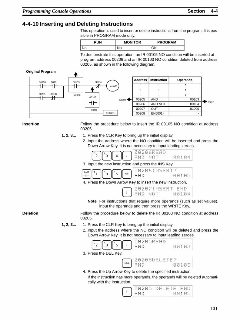
4-4SectionProgramming Console Operations
131
4-4-10 Inserting and Deleting InstructionsThis operation is used to insert or delete instructions from the program. It is pos-sible in PROGRAM mode only.
RUN MONITOR PROGRAM
No No OK
To demonstrate this operation, an IR 00105 NO condition will be inserted atprogram address 00206 and an IR 00103 NO condition deleted from address00205, as shown in the following diagram.
0010400100 00103
00105
00101
00201
END(01)
00102
01000
Delete
Insert
Original Program
Address Instruction Operands
00205 AND 00103
00206 AND NOT 00104
00207 OUT 01000
00208 END(01) -
DeleteInsert
Insertion Follow the procedure below to insert the IR 00105 NO condition at address00206.
1, 2, 3... 1. Press the CLR Key to bring up the initial display.2. Input the address where the NO condition will be inserted and press the
Down Arrow Key. It is not necessary to input leading zeroes.
C2
A0 6 ↓
,
/
3. Input the new instruction and press the INS Key.
AND B1
A0
F5 INS
,
+
4. Press the Down Arrow Key to insert the new instruction.
↓ "
/
Note For instructions that require more operands (such as set values),input the operands and then press the WRITE Key.
Deletion Follow the procedure below to delete the IR 00103 NO condition at address00205.
1, 2, 3... 1. Press the CLR Key to bring up the initial display.2. Input the address where the NO condition will be deleted and press the
Down Arrow Key. It is not necessary to input leading zeroes.
C2
A0
F5 ↓
+
3. Press the DEL Key.
DEL +
4. Press the Up Arrow Key to delete the specified instruction.If the instruction has more operands, the operands will be deleted automati-cally with the instruction.
↑ +
+
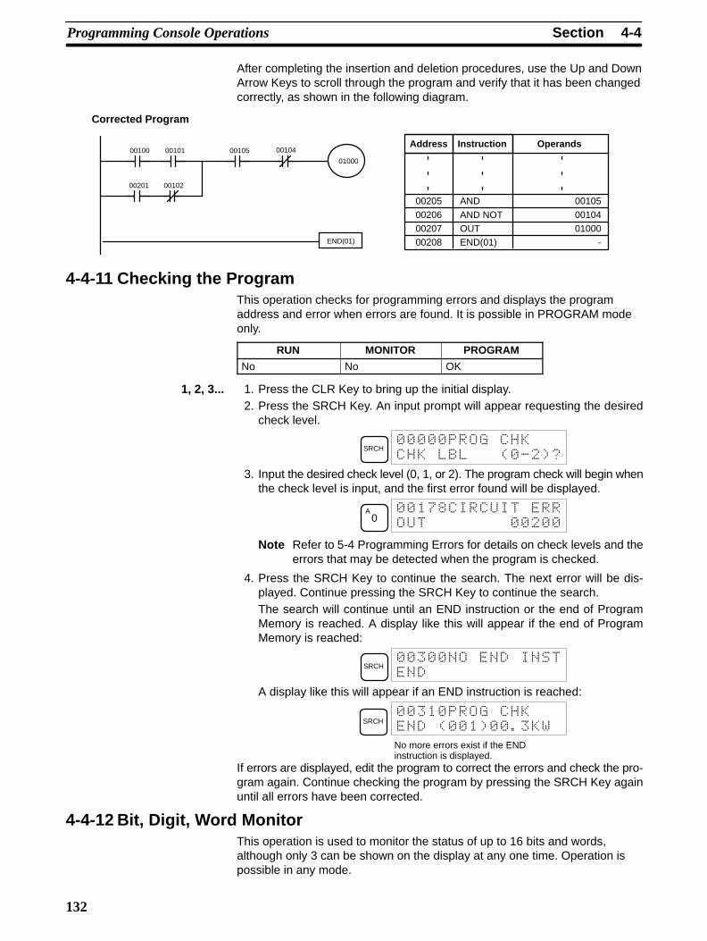
4-4SectionProgramming Console Operations
132
After completing the insertion and deletion procedures, use the Up and DownArrow Keys to scroll through the program and verify that it has been changedcorrectly, as shown in the following diagram.
0010400100 0010500101
00201
END(01)
00102
01000
Corrected Program
Address Instruction Operands
00205 AND 00105
00206 AND NOT 00104
00207 OUT 01000
00208 END(01) -
4-4-11 Checking the ProgramThis operation checks for programming errors and displays the programaddress and error when errors are found. It is possible in PROGRAM modeonly.
RUN MONITOR PROGRAM
No No OK
1, 2, 3... 1. Press the CLR Key to bring up the initial display.2. Press the SRCH Key. An input prompt will appear requesting the desired
check level.
SRCH
' .(
3. Input the desired check level (0, 1, or 2). The program check will begin whenthe check level is input, and the first error found will be displayed.
A0
"$
Note Refer to 5-4 Programming Errors for details on check levels and theerrors that may be detected when the program is checked.
4. Press the SRCH Key to continue the search. The next error will be dis-played. Continue pressing the SRCH Key to continue the search.The search will continue until an END instruction or the end of ProgramMemory is reached. A display like this will appear if the end of ProgramMemory is reached:
SRCH
A display like this will appear if an END instruction is reached:
SRCH
' ( 1
No more errors exist if the ENDinstruction is displayed.
If errors are displayed, edit the program to correct the errors and check the pro-gram again. Continue checking the program by pressing the SRCH Key againuntil all errors have been corrected.
4-4-12 Bit, Digit, Word MonitorThis operation is used to monitor the status of up to 16 bits and words,although only 3 can be shown on the display at any one time. Operation ispossible in any mode.
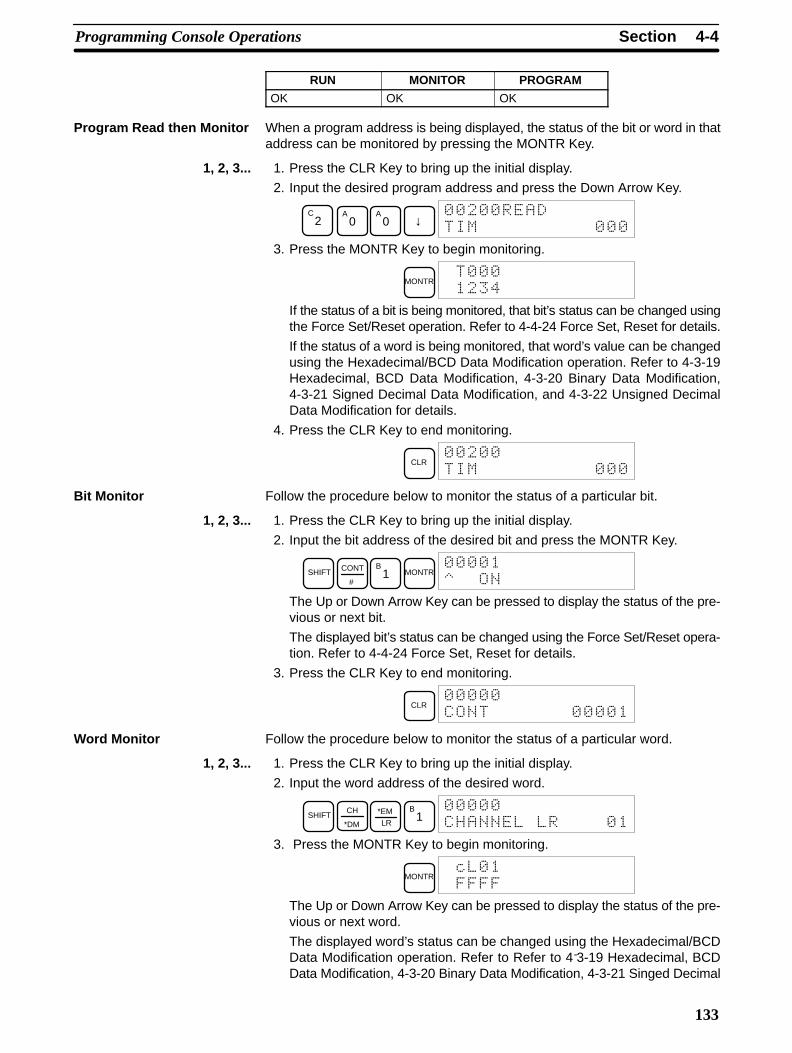
4-4SectionProgramming Console Operations
133
RUN MONITOR PROGRAM
OK OK OK
Program Read then Monitor When a program address is being displayed, the status of the bit or word in thataddress can be monitored by pressing the MONTR Key.
1, 2, 3... 1. Press the CLR Key to bring up the initial display.
2. Input the desired program address and press the Down Arrow Key.
C2
A0
A0 ↓
3. Press the MONTR Key to begin monitoring.
MONTR
/
If the status of a bit is being monitored, that bit’s status can be changed usingthe Force Set/Reset operation. Refer to 4-4-24 Force Set, Reset for details.
If the status of a word is being monitored, that word’s value can be changedusing the Hexadecimal/BCD Data Modification operation. Refer to 4-3-19Hexadecimal, BCD Data Modification, 4-3-20 Binary Data Modification,4-3-21 Signed Decimal Data Modification, and 4-3-22 Unsigned DecimalData Modification for details.
4. Press the CLR Key to end monitoring.
CLR
Bit Monitor Follow the procedure below to monitor the status of a particular bit.
1, 2, 3... 1. Press the CLR Key to bring up the initial display.
2. Input the bit address of the desired bit and press the MONTR Key.
SHIFT CONT
#
B1 MONTR
The Up or Down Arrow Key can be pressed to display the status of the pre-vious or next bit.
The displayed bit’s status can be changed using the Force Set/Reset opera-tion. Refer to 4-4-24 Force Set, Reset for details.
3. Press the CLR Key to end monitoring.
CLR
Word Monitor Follow the procedure below to monitor the status of a particular word.
1, 2, 3... 1. Press the CLR Key to bring up the initial display.
2. Input the word address of the desired word.
SHIFTCH
*DM LR
*EM B1
3. Press the MONTR Key to begin monitoring.
MONTR2
!!!!
The Up or Down Arrow Key can be pressed to display the status of the pre-vious or next word.
The displayed word’s status can be changed using the Hexadecimal/BCDData Modification operation. Refer to Refer to 4-3-19 Hexadecimal, BCDData Modification, 4-3-20 Binary Data Modification, 4-3-21 Singed Decimal

4-4SectionProgramming Console Operations
134
Data Modification, and 4-3-22 Unsigned Decimal Data Modification for de-tails.
4. Press the CLR Key to end monitoring.
CLR
Note The operating mode can be changed without altering the current monitor displayby holding down the SHIFT Key and then changing the operating mode.
The status of up to six bits and words can be monitored simultaneously, althoughonly three can be shown on the display at any one time.
1, 2, 3... 1. Press the CLR Key to bring up the initial display.
2. Input the address of the first bit or word and press the MONTR Key.
TIM MONTR
3. Repeat step 2 up to 6 times to display the next addresses to be monitored.
SHIFT CONT
#
B1 MONTR
!!
DM
EM MONTR
!!
If 4 or more bits and words are being monitored, the bits and words that donot appear on the display can be displayed by pressing the MONTR Key. Ifthe MONTR Key is pressed alone, the display will shift to the right.
If more than six bits and words are input, monitoring of the bit or word inputfirst will be canceled.
4. Press the CLR Key to stop monitoring the leftmost bit or word and clear itfrom the display.
CLR
!!
5. Press the SHIFT and CLR Keys to end monitoring altogether.
SHIFT CLR
Note Press the SHIFT Key, CLR Key, and then CLR Key again to return to the initialProgramming Console display with the multiple address monitoring stateunchanged. Press the SHIFT Key and then the MONTR Key from the initial dis-play to return to the multiple address monitoring state. The monitoring states canbe retained for 6 bits and words.The operating mode can be changed without altering the current monitor displayby holding down the SHIFT Key and then changing the operating mode.
4-4-13 Differentiation MonitorThis operation is used to monitor the up or down differentiation status of aparticular bit. When detected, the up or down differentiation will be displayedand the buzzer will sound. It is possible in any mode.
RUN MONITOR PROGRAM
OK OK OK
1, 2, 3... 1. Monitor the status of the desired bit according to the procedure described in4-4-12 Bit, Digit, Word Monitor. If 2 or more bits are being monitored, the de-sired bit should be leftmost on the display.
Multiple AddressMonitoring
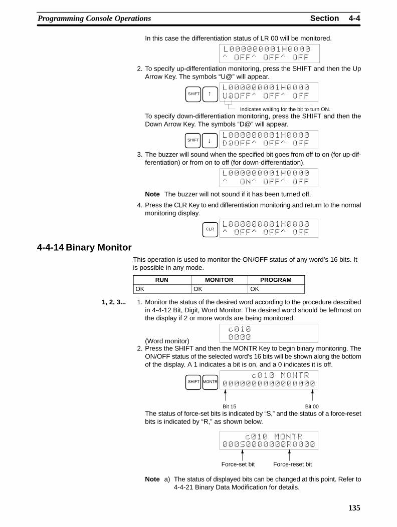
4-4SectionProgramming Console Operations
135
In this case the differentiation status of LR 00 will be monitored.
!!!!!!
2. To specify up-differentiation monitoring, press the SHIFT and then the UpArrow Key. The symbols “U@” will appear.
SHIFT ↑
3!!!!!!
Indicates waiting for the bit to turn ON.To specify down-differentiation monitoring, press the SHIFT and then theDown Arrow Key. The symbols “D@” will appear.
SHIFT ↓
3!!!!!!
3. The buzzer will sound when the specified bit goes from off to on (for up-dif-ferentiation) or from on to off (for down-differentiation).
!!!!
Note The buzzer will not sound if it has been turned off.
4. Press the CLR Key to end differentiation monitoring and return to the normalmonitoring display.
CLR
!!!!!!
4-4-14 Binary MonitorThis operation is used to monitor the ON/OFF status of any word’s 16 bits. Itis possible in any mode.
RUN MONITOR PROGRAM
OK OK OK
1, 2, 3... 1. Monitor the status of the desired word according to the procedure describedin 4-4-12 Bit, Digit, Word Monitor. The desired word should be leftmost onthe display if 2 or more words are being monitored.
(Word monitor)
2
2. Press the SHIFT and then the MONTR Key to begin binary monitoring. TheON/OFF status of the selected word’s 16 bits will be shown along the bottomof the display. A 1 indicates a bit is on, and a 0 indicates it is off.
SHIFT MONTR2
Bit 15 Bit 00The status of force-set bits is indicated by “S,” and the status of a force-resetbits is indicated by “R,” as shown below.
Force-set bit
Force-reset bit
2
Note a) The status of displayed bits can be changed at this point. Refer to4-4-21 Binary Data Modification for details.
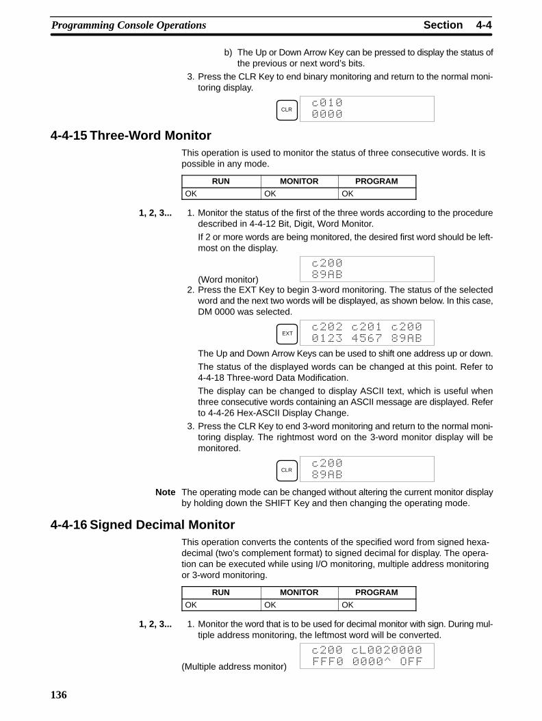
4-4SectionProgramming Console Operations
136
b) The Up or Down Arrow Key can be pressed to display the status ofthe previous or next word’s bits.
3. Press the CLR Key to end binary monitoring and return to the normal moni-toring display.
CLR2
4-4-15 Three-Word MonitorThis operation is used to monitor the status of three consecutive words. It ispossible in any mode.
RUN MONITOR PROGRAM
OK OK OK
1, 2, 3... 1. Monitor the status of the first of the three words according to the proceduredescribed in 4-4-12 Bit, Digit, Word Monitor.
If 2 or more words are being monitored, the desired first word should be left-most on the display.
(Word monitor)
2
$0
2. Press the EXT Key to begin 3-word monitoring. The status of the selectedword and the next two words will be displayed, as shown below. In this case,DM 0000 was selected.
EXT2 2 2
/+,"$0
The Up and Down Arrow Keys can be used to shift one address up or down.
The status of the displayed words can be changed at this point. Refer to4-4-18 Three-word Data Modification.
The display can be changed to display ASCII text, which is useful whenthree consecutive words containing an ASCII message are displayed. Referto 4-4-26 Hex-ASCII Display Change.
3. Press the CLR Key to end 3-word monitoring and return to the normal moni-toring display. The rightmost word on the 3-word monitor display will bemonitored.
CLR2
$0
Note The operating mode can be changed without altering the current monitor displayby holding down the SHIFT Key and then changing the operating mode.
4-4-16 Signed Decimal MonitorThis operation converts the contents of the specified word from signed hexa-decimal (two’s complement format) to signed decimal for display. The opera-tion can be executed while using I/O monitoring, multiple address monitoringor 3-word monitoring.
RUN MONITOR PROGRAM
OK OK OK
1, 2, 3... 1. Monitor the word that is to be used for decimal monitor with sign. During mul-tiple address monitoring, the leftmost word will be converted.
(Multiple address monitor)
2 2
!!! !!
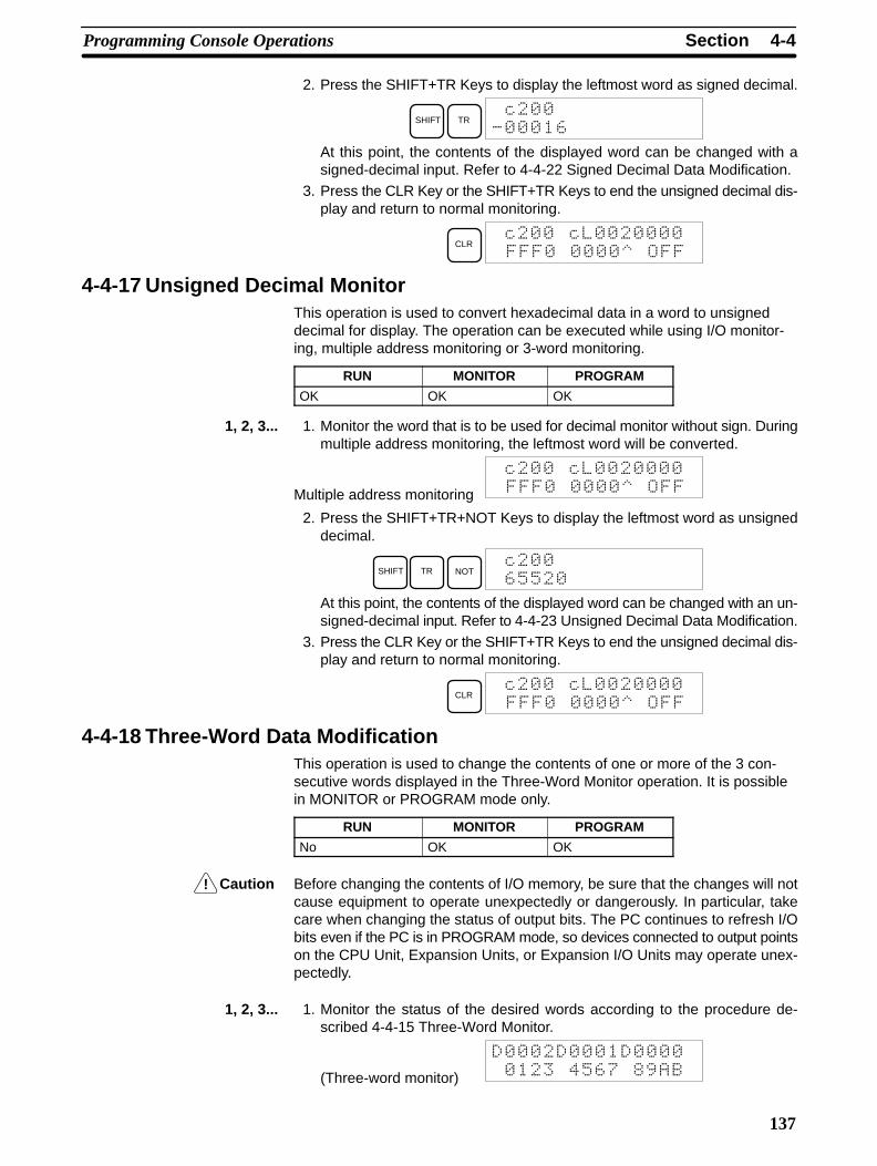
!
4-4SectionProgramming Console Operations
137
2. Press the SHIFT+TR Keys to display the leftmost word as signed decimal.
SHIFT TR2
. ,
At this point, the contents of the displayed word can be changed with asigned-decimal input. Refer to 4-4-22 Signed Decimal Data Modification.
3. Press the CLR Key or the SHIFT+TR Keys to end the unsigned decimal dis-play and return to normal monitoring.
CLR2 2
!!! !!
4-4-17 Unsigned Decimal MonitorThis operation is used to convert hexadecimal data in a word to unsigneddecimal for display. The operation can be executed while using I/O monitor-ing, multiple address monitoring or 3-word monitoring.
RUN MONITOR PROGRAM
OK OK OK
1, 2, 3... 1. Monitor the word that is to be used for decimal monitor without sign. Duringmultiple address monitoring, the leftmost word will be converted.
Multiple address monitoring
2 2
!!! !!
2. Press the SHIFT+TR+NOT Keys to display the leftmost word as unsigneddecimal.
SHIFT TR NOT2
,++
At this point, the contents of the displayed word can be changed with an un-signed-decimal input. Refer to 4-4-23 Unsigned Decimal Data Modification.
3. Press the CLR Key or the SHIFT+TR Keys to end the unsigned decimal dis-play and return to normal monitoring.
CLR2 2
!!! !!
4-4-18 Three-Word Data ModificationThis operation is used to change the contents of one or more of the 3 con-secutive words displayed in the Three-Word Monitor operation. It is possiblein MONITOR or PROGRAM mode only.
RUN MONITOR PROGRAM
No OK OK
Caution Before changing the contents of I/O memory, be sure that the changes will notcause equipment to operate unexpectedly or dangerously. In particular, takecare when changing the status of output bits. The PC continues to refresh I/Obits even if the PC is in PROGRAM mode, so devices connected to output pointson the CPU Unit, Expansion Units, or Expansion I/O Units may operate unex-pectedly.
1, 2, 3... 1. Monitor the status of the desired words according to the procedure de-scribed 4-4-15 Three-Word Monitor.
(Three-word monitor)
/+,"$0

4-4SectionProgramming Console Operations
138
2. Press the CHG Key to begin 3-word data modification. The cursor will ap-pear next to the contents of the leftmost word.
CHG
/+,"$0
3. Input the new value for the leftmost word on the display and press the CHGKey if more changes will be made.(Input the new value and press the WRITE Key to write the changes inmemory if no more changes will be made.)
B1 CHG
/+,"$0
4. Input the new value for the middle word on the display and press the CHGKey if the rightmost word will be changed. Input the new value and press theWRITE Key to write the changes in memory if the rightmost word will not bechanged. (In this case, it will not.)
C2
D3
E4 WRITE
/$0
Note If the CLR Key is pressed before the WRITE Key, the operation will be cancelledand the 3-word monitor display will return without any changes in data memory.
4-4-19 Changing Timer, Counter SVThere are two operations that can be used to change the SV of a timer orcounter. They are possible in MONITOR or PROGRAM mode only. In MON-ITOR mode, the SV can be changed while the program is being executed.
RUN MONITOR PROGRAM
No OK OK
The timer or counter SV can be changed either by inputting a new value orby incrementing or decrementing the current SV.
This operation can be used to input a new SV constant, as well as to change anSV from a constant to a word address designation and vice versa. The followingexamples show how to input a new SV constant and how to change the SV froma constant to an address.
1, 2, 3... 1. Press the CLR Key to bring up the initial display.
2. Display the desired timer or counter.
TIMB
1 SRCH
3. Press the Down Arrow Key and then the CHG Key.
↓ CHG
) /)
4. At this point a new SV constant can be input or the SV constant can bechanged to a word address designationa) To input a new SV constant, input the constant and press the WRITE
Key.
B1
C2
E4 WRITE
) /
b) To change to a word address designation, input the word address andpress the WRITE Key.
SHIFTCH
*DM
AR
HR
B1
A0 WRITE
Inputting a New SVConstant
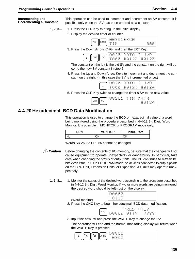
!
4-4SectionProgramming Console Operations
139
This operation can be used to increment and decrement an SV constant. It ispossible only when the SV has been entered as a constant.
1, 2, 3... 1. Press the CLR Key to bring up the initial display.
2. Display the desired timer or counter.
TIM SRCH
3. Press the Down Arrow, CHG, and then the EXT Key.
↓ CHG EXT
) )
The constant on the left is the old SV and the constant on the right will be-come the new SV constant in step 5.
4. Press the Up and Down Arrow Keys to increment and decrement the con-stant on the right. (In this case the SV is incremented once.)
↓
) ) /
5. Press the CLR Key twice to change the timer’s SV to the new value.
CLR CLR
) /
4-4-20 Hexadecimal, BCD Data ModificationThis operation is used to change the BCD or hexadecimal value of a wordbeing monitored using the procedure described in 4-4-12 Bit, Digit, WordMonitor. It is possible in MONITOR or PROGRAM mode only.
RUN MONITOR PROGRAM
No OK OK
Words SR 253 to SR 255 cannot be changed.
Caution Before changing the contents of I/O memory, be sure that the changes will notcause equipment to operate unexpectedly or dangerously. In particular, takecare when changing the status of output bits. The PC continues to refresh I/Obits even if the PC is in PROGRAM mode, so devices connected to output pointson the CPU Unit, Expansion Units, or Expansion I/O Units may operate unex-pectedly.
1, 2, 3... 1. Monitor the status of the desired word according to the procedure describedin 4-4-12 Bit, Digit, Word Monitor. If two or more words are being monitored,the desired word should be leftmost on the display.
(Word monitor)
0
2. Press the CHG Key to begin hexadecimal, BCD data modification.
CHG*
0
3. Input the new PV and press the WRITE Key to change the PV.
The operation will end and the normal monitoring display will return whenthe WRITE Key is pressed.
C2
A0
A0 WRITE
Incrementing andDecrementing a Constant
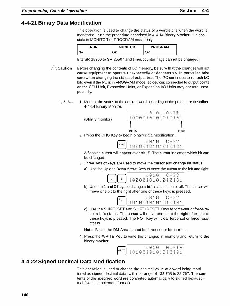
!
4-4SectionProgramming Console Operations
140
4-4-21 Binary Data ModificationThis operation is used to change the status of a word’s bits when the word ismonitored using the procedure described in 4-4-14 Binary Monitor. It is pos-sible in MONITOR or PROGRAM mode only.
RUN MONITOR PROGRAM
No OK OK
Bits SR 25300 to SR 25507 and timer/counter flags cannot be changed.
Caution Before changing the contents of I/O memory, be sure that the changes will notcause equipment to operate unexpectedly or dangerously. In particular, takecare when changing the status of output bits. The PC continues to refresh I/Obits even if the PC is in PROGRAM mode, so devices connected to output pointson the CPU Unit, Expansion Units, or Expansion I/O Units may operate unex-pectedly.
1, 2, 3... 1. Monitor the status of the desired word according to the procedure described4-4-14 Binary Monitor.
(BInary monitor)
2
Bit 15 Bit 002. Press the CHG Key to begin binary data modification.
CHG2
A flashing cursor will appear over bit 15. The cursor indicates which bit canbe changed.
3. Three sets of keys are used to move the cursor and change bit status:
a) Use the Up and Down Arrow Keys to move the cursor to the left and right.
↓ ↓2
b) Use the 1 and 0 Keys to change a bit’s status to on or off. The cursor willmove one bit to the right after one of these keys is pressed.
B1
2
c) Use the SHIFT+SET and SHIFT+RESET Keys to force-set or force-re-set a bit’s status. The cursor will move one bit to the right after one ofthese keys is pressed. The NOT Key will clear force-set or force-resetstatus.
Note Bits in the DM Area cannot be force-set or force-reset.
4. Press the WRITE Key to write the changes in memory and return to thebinary monitor.
WRITE2
4-4-22 Signed Decimal Data ModificationThis operation is used to change the decimal value of a word being moni-tored as signed decimal data, within a range of –32,768 to 32,767. The con-tents of the specified word are converted automatically to signed hexadeci-mal (two’s complement format).
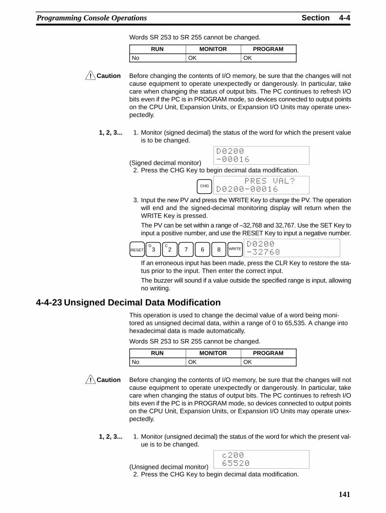
!
!
4-4SectionProgramming Console Operations
141
Words SR 253 to SR 255 cannot be changed.
RUN MONITOR PROGRAM
No OK OK
Caution Before changing the contents of I/O memory, be sure that the changes will notcause equipment to operate unexpectedly or dangerously. In particular, takecare when changing the status of output bits. The PC continues to refresh I/Obits even if the PC is in PROGRAM mode, so devices connected to output pointson the CPU Unit, Expansion Units, or Expansion I/O Units may operate unex-pectedly.
1, 2, 3... 1. Monitor (signed decimal) the status of the word for which the present valueis to be changed.
(Signed decimal monitor)
. ,
2. Press the CHG Key to begin decimal data modification.
CHG*
. ,
3. Input the new PV and press the WRITE Key to change the PV. The operationwill end and the signed-decimal monitoring display will return when theWRITE Key is pressed.
The PV can be set within a range of –32,768 and 32,767. Use the SET Key toinput a positive number, and use the RESET Key to input a negative number.
RESETD
3C
2 7 6 8 WRITE
.",$
If an erroneous input has been made, press the CLR Key to restore the sta-tus prior to the input. Then enter the correct input.
The buzzer will sound if a value outside the specified range is input, allowingno writing.
4-4-23 Unsigned Decimal Data ModificationThis operation is used to change the decimal value of a word being moni-tored as unsigned decimal data, within a range of 0 to 65,535. A change intohexadecimal data is made automatically.
Words SR 253 to SR 255 cannot be changed.
RUN MONITOR PROGRAM
No OK OK
Caution Before changing the contents of I/O memory, be sure that the changes will notcause equipment to operate unexpectedly or dangerously. In particular, takecare when changing the status of output bits. The PC continues to refresh I/Obits even if the PC is in PROGRAM mode, so devices connected to output pointson the CPU Unit, Expansion Units, or Expansion I/O Units may operate unex-pectedly.
1, 2, 3... 1. Monitor (unsigned decimal) the status of the word for which the present val-ue is to be changed.
(Unsigned decimal monitor)
2
,++
2. Press the CHG Key to begin decimal data modification.

!
4-4SectionProgramming Console Operations
142
CHG*
2 ,++
3. Input the new PV and press the WRITE Key to change the PV. The operationwill end and the decimal-without-sign monitoring display will return when theWRITE Key is pressed.
The PV can be set within a range of 0 to 65,535.
D3
C2 7 6 8 WRITE
2
",$
If an erroneous input has been made, press the CLR Key to restore the sta-tus prior to the input. Then enter the correct input.
The buzzer will sound if a value outside the specified range is input, allowingno writing.
4-4-24 Force Set, ResetThis operation is used to force bits ON (force set) or OFF (force reset) and isuseful when debugging the program or checking output wiring. It is possiblein MONITOR or PROGRAM mode only.
RUN MONITOR PROGRAM
No OK OK
Caution Before changing the contents of I/O memory, be sure that the changes will notcause equipment to operate unexpectedly or dangerously. In particular, takecare when changing the status of output bits. The PC continues to refresh I/Obits even if the PC is in PROGRAM mode, so devices connected to output pointson the CPU Unit, Expansion Units, or Expansion I/O Units may operate unex-pectedly.
1, 2, 3... 1. Monitor the status of the desired bit according to the procedure described in4-4-12 Bit, Digit, Word Monitor. If two or more words are being monitored,the desired bit should be leftmost on the display.
(Multiple address monitor)
!!
2. Press the SET Key to force the bit ON or press the RESET Key to force thebit OFF.
SET
The cursor in the lower left corner of the display indicates that the force set/reset is in progress. Bit status will remain ON or OFF only as long as the keyis held down; the original status will return one cycle after the key is re-leased.
3. Press the SHIFT and SET Keys or SHIFT and RESET Keys to maintain thestatus of the bit after the key is released. In this case, the force-set status isindicated by an “S” and the force-reset status is indicated by an “R.”
To return the bit to its original status, press the NOT Key or perform the ClearForce Set/Reset operation. Refer to 4-4-25 Clear Force Set/Reset for de-tails.
Forced status will also be cleared in the following cases:
a) When the PC’s operating mode is changed (although the forced statuswill not be cleared when the mode is changed from PROGRAM to MON-ITOR if SR 25211 is ON)
b) When the PC stops because a fatal error occurred

!
4-4SectionProgramming Console Operations
143
c) When the PC stops because of a power interruption
d) When the Clear Force Set/Reset Operation is performed
4-4-25 Clear Force Set/ResetThis operation is used to restore the status of all bits which have been forceset or reset. It is possible in MONITOR or PROGRAM mode only.
RUN MONITOR PROGRAM
No OK OK
Caution Before changing the contents of I/O memory, be sure that the changes will notcause equipment to operate unexpectedly or dangerously. In particular, takecare when changing the status of output bits. The PC continues to refresh I/Obits even if the PC is in PROGRAM mode, so devices connected to output pointson the CPU Unit, Expansion Units, or Expansion I/O Units may operate unex-pectedly.
1, 2, 3... 1. Press the CLR Key to bring up the initial display.
2. Press the SET and then the RESET Key. A confirmation message will ap-pear.
SET RESET !
Note If you mistakenly press the wrong key, press CLR and start againfrom the beginning.
3. Press the NOT Key to clear the force-set/reset status of bits in all data areas.
NOT !
4-4-26 Hex-ASCII Display ChangeThis operation is used to convert word data displays back and forth between4-digit hexadecimal data and ASCII. It is possible in any mode.
The displayed PV of the timer or counter cannot be changed.
RUN MONITOR PROGRAM
OK OK OK
1, 2, 3... 1. Monitor the status of the desired word(s) according to the procedure de-scribed in 4-4-12 Bit, Digit, Word Monitor. While the multiple addresses arebeing monitored, the leftmost word is subject to change.
(Multiple address monitor)
//
2. Press the TR Key to switch to ASCII display. The display will toggle betweenhexadecimal and ASCII displays each time the TR Key is pressed.
TR
44
TR
//
Note 1. A message contained in three words can be displayed by using ASCII dis-play in combination with the Three-word monitor operation.
2. The Hexadecimal, BCD Data Modification Operation can be used while dis-playing ASCII data. Input values in 4-digit hexadecimal.
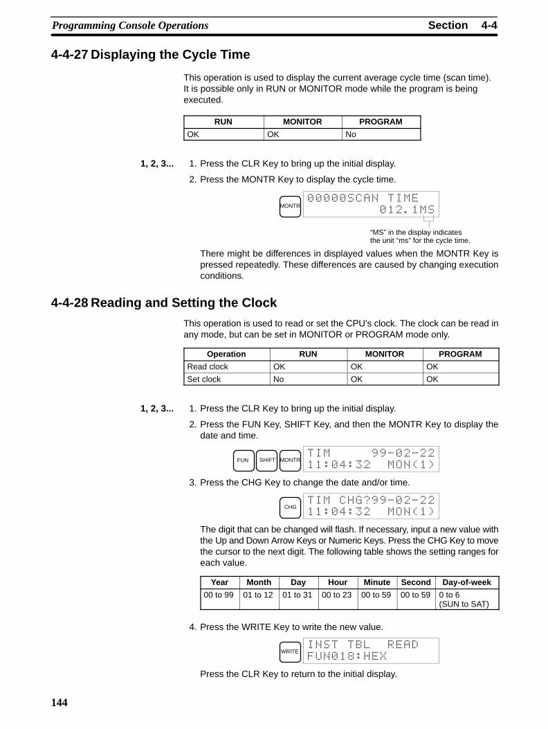
4-4SectionProgramming Console Operations
144
4-4-27 Displaying the Cycle Time
This operation is used to display the current average cycle time (scan time).It is possible only in RUN or MONITOR mode while the program is beingexecuted.
RUN MONITOR PROGRAM
OK OK No
1, 2, 3... 1. Press the CLR Key to bring up the initial display.
2. Press the MONTR Key to display the cycle time.
MONTR
1
“MS” in the display indicatesthe unit “ms” for the cycle time.
There might be differences in displayed values when the MONTR Key ispressed repeatedly. These differences are caused by changing executionconditions.
4-4-28 Reading and Setting the Clock
This operation is used to read or set the CPU’s clock. The clock can be read inany mode, but can be set in MONITOR or PROGRAM mode only.
Operation RUN MONITOR PROGRAM
Read clock OK OK OK
Set clock No OK OK
1, 2, 3... 1. Press the CLR Key to bring up the initial display.
2. Press the FUN Key, SHIFT Key, and then the MONTR Key to display thedate and time.
FUN SHIFT MONTR00. .
# /#'(
3. Press the CHG Key to change the date and/or time.
CHG00. .
# /#'(
The digit that can be changed will flash. If necessary, input a new value withthe Up and Down Arrow Keys or Numeric Keys. Press the CHG Key to movethe cursor to the next digit. The following table shows the setting ranges foreach value.
Year Month Day Hour Minute Second Day-of-week
00 to 99 01 to 12 01 to 31 00 to 23 00 to 59 00 to 59 0 to 6(SUN to SAT)
4. Press the WRITE Key to write the new value.
WRITE
! $#&
Press the CLR Key to return to the initial display.
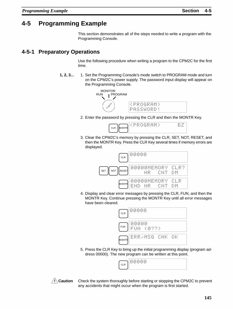
!
4-5SectionProgramming Example
145
4-5 Programming Example
This section demonstrates all of the steps needed to write a program with theProgramming Console.
4-5-1 Preparatory Operations
Use the following procedure when writing a program to the CPM2C for the firsttime.
1, 2, 3... 1. Set the Programming Console’s mode switch to PROGRAM mode and turnon the CPM2C’s power supply. The password input display will appear onthe Programming Console.
RUNMONITOR
PROGRAM
2. Enter the password by pressing the CLR and then the MONTR Key.
CLR MONTR
3. Clear the CPM2C’s memory by pressing the CLR, SET, NOT, RESET, andthen the MONTR Key. Press the CLR Key several times if memory errors aredisplayed.
CLR
SET NOT RESET
MONTR
4. Display and clear error messages by pressing the CLR, FUN, and then theMONTR Key. Continue pressing the MONTR Key until all error messageshave been cleared.
CLR
FUN
!' (
MONTR
5. Press the CLR Key to bring up the initial programming display (program ad-dress 00000). The new program can be written at this point.
CLR
Caution Check the system thoroughly before starting or stopping the CPM2C to preventany accidents that might occur when the program is first started.

4-5SectionProgramming Example
146
4-5-2 Example ProgramThe following ladder program will be used to demonstrate how to write a pro-gram with the Programming Console. This program makes output IR 01000flicker ON/OFF (one second ON, one second OFF) ten times after inputIR 00000 is turned ON.
Count input
Reset input
20000
END(01)
C00000000
20000
01000
T00120000
00000
00004
00007
00010
00014
000171S
ONOFF
Self-holding bit
1-second timer
2-second timer
10-count counter
Flicker output (10 counts)
TIM 001
#0010
CP
R
CNT 000
#0010
T00220000
TIM 002
#0020
T00220000
T00120000
20000
Start input
The mnemonic list for the example program is shown in the following table. Thesteps required to enter this program from a Programming Console are describedin 4-5-3 Programming Procedures.
Address Instruction Data Programming exampleprocedures in 4-5-3
Programming Procedures
00000 LD 00000 (1) Self-holding bit
00001 OR 20000
00002 AND NOT C 000
00003 OUT 20000
00004 LD 20000 (2) 1-second timer
00005 AND NOT T 002
00006 TIM 001
# 0010
00007 LD 20000 (3) 2-second timer
00008 AND NOT T 002
00009 TIM 002
# 0020
00010 LD 20000 (4) 10-count counter
00011 AND T 001
00012 LD NOT 20000
00013 CNT 000
# 0010
00014 LD 20000 (5) Flicker output (10 counts)
00015 AND NOT T 001
00016 OUT 01000
00017 END (01) --- (6) END(01) instruction
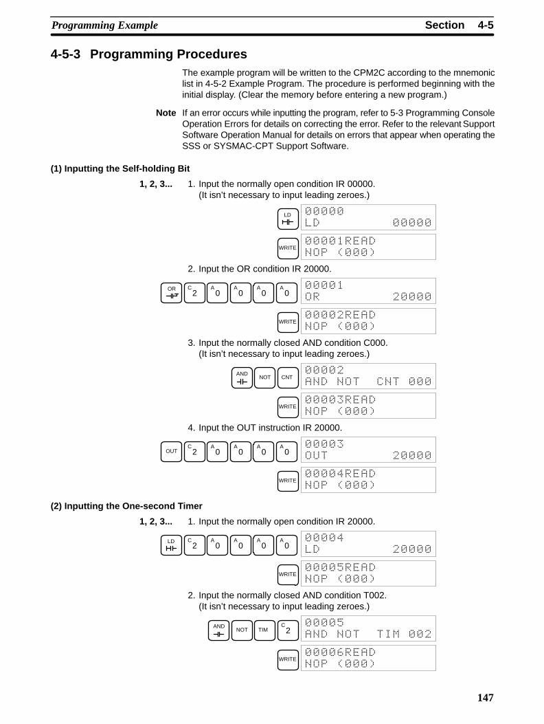
4-5SectionProgramming Example
147
4-5-3 Programming ProceduresThe example program will be written to the CPM2C according to the mnemoniclist in 4-5-2 Example Program. The procedure is performed beginning with theinitial display. (Clear the memory before entering a new program.)
Note If an error occurs while inputting the program, refer to 5-3 Programming ConsoleOperation Errors for details on correcting the error. Refer to the relevant SupportSoftware Operation Manual for details on errors that appear when operating theSSS or SYSMAC-CPT Support Software.
(1) Inputting the Self-holding Bit
1, 2, 3... 1. Input the normally open condition IR 00000.(It isn’t necessary to input leading zeroes.)
LD
WRITE
' (
2. Input the OR condition IR 20000.
OR C2
A0
A0
A0
A0
WRITE
' (
3. Input the normally closed AND condition C000.(It isn’t necessary to input leading zeroes.)
ANDNOT CNT
WRITE
' (
4. Input the OUT instruction IR 20000.
OUTC
2A
0A
0A
0A
0
WRITE /
' (
(2) Inputting the One-second Timer
1, 2, 3... 1. Input the normally open condition IR 20000.
LD C2
A0
A0
A0
A0
/
WRITE +
' (
2. Input the normally closed AND condition T002.(It isn’t necessary to input leading zeroes.)
ANDNOT TIM
C2
+
WRITE ,
' (
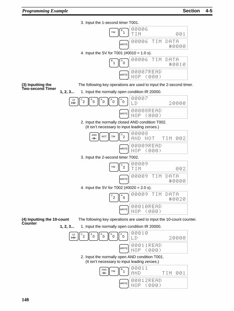
4-5SectionProgramming Example
148
3. Input the 1-second timer T001.
TIMB
1 ,
WRITE ,
)
4. Input the SV for T001 (#0010 = 1.0 s).
B1
A0
,
)
WRITE "
' (
The following key operations are used to input the 2-second timer.
1, 2, 3... 1. Input the normally open condition IR 20000.
LD C2
A0
A0
A0
A0
"
WRITE $
' (
2. Input the normally closed AND condition T002.(It isn’t necessary to input leading zeroes.)
ANDNOT TIM
C2
$
WRITE 0
' (
3. Input the 2-second timer T002.
TIMC
2 0
WRITE 0
)
4. Input the SV for T002 (#0020 = 2.0 s).
C2
A0
0
)
WRITE
' (
The following key operations are used to input the 10-count counter.
1, 2, 3... 1. Input the normally open condition IR 20000.
LD C2
A0
A0
A0
A0
WRITE
' (
2. Input the normally open AND condition T001.(It isn’t necessary to input leading zeroes.)
ANDTIM
B1
WRITE
' (
(3) Inputting theTwo-second Timer
(4) Inputting the 10-countCounter
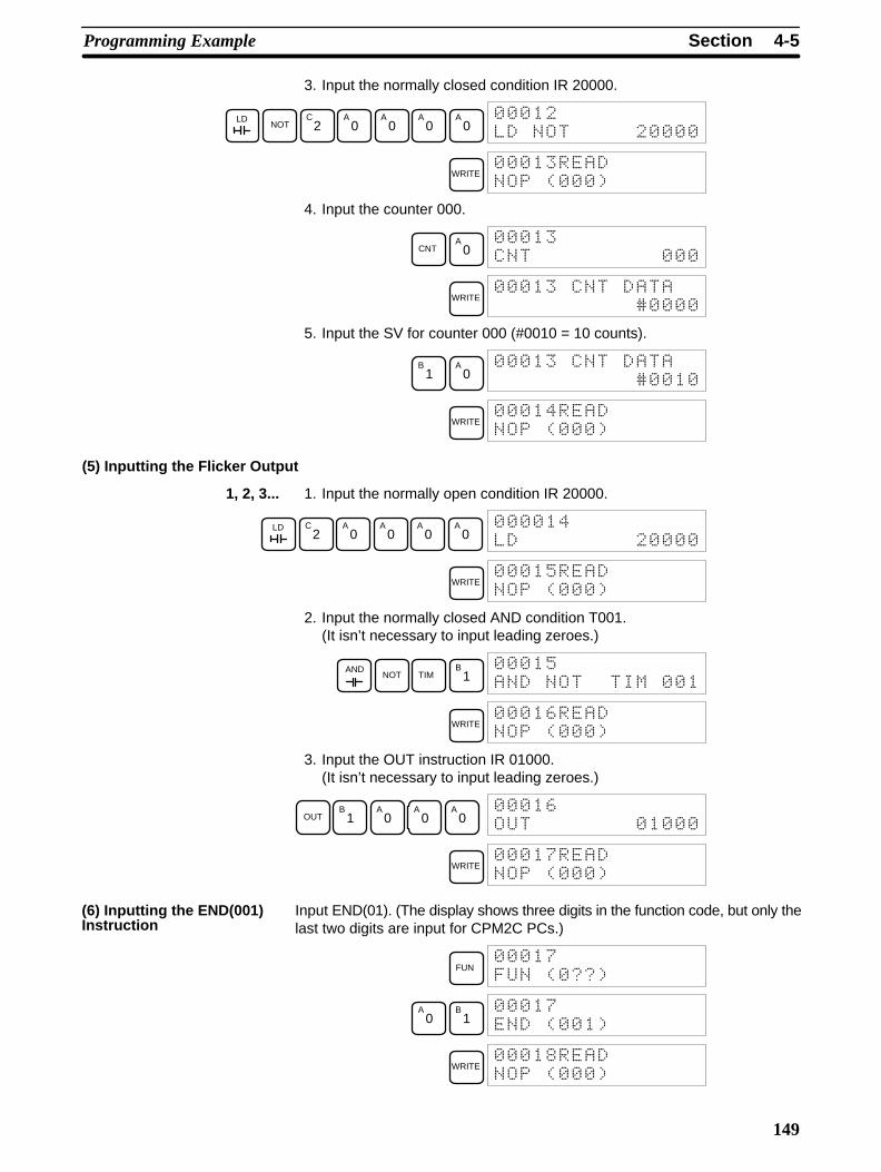
4-5SectionProgramming Example
149
3. Input the normally closed condition IR 20000.
LDNOT
C2
A0
A0
A0
A0
WRITE
' (
4. Input the counter 000.
CNTA
0
WRITE
)
5. Input the SV for counter 000 (#0010 = 10 counts).
B1
A0
)
WRITE /
' (
(5) Inputting the Flicker Output
1, 2, 3... 1. Input the normally open condition IR 20000.
LD C2
A0
A0
A0
A0
/
WRITE +
' (
2. Input the normally closed AND condition T001.(It isn’t necessary to input leading zeroes.)
ANDNOT TIM
B1
+
WRITE ,
' (
3. Input the OUT instruction IR 01000.(It isn’t necessary to input leading zeroes.)
OUTB
1A
0A
0A
0 ,
WRITE "
' (
Input END(01). (The display shows three digits in the function code, but only thelast two digits are input for CPM2C PCs.)
FUN "
!' (
A0
B1
"
' (
WRITE $
' (
(6) Inputting the END(001)Instruction

4-5SectionProgramming Example
150
4-5-4 Checking the ProgramCheck the program syntax in PROGRAM mode to make sure that the programhas been input correctly.
1, 2, 3... 1. Press the CLR Key to bring up the initial display.
CLR
2. Press the SRCH Key. An input prompt will appear requesting the desiredcheck level.
SRCH
' .(
3. Input the desired check level (0, 1, or 2). The program check will begin whenthe check level is input, and the first error found will be displayed. If no errorsare found, the following display will appear.
A0
"
' ( 1
Note Refer to 5-4 Programming Errors for details on check levels and theprogramming errors that may be displayed during a program check.
4. Press the SRCH Key to continue the search. The next error will be dis-played. Continue pressing the SRCH Key to continue the search.The search will continue until an END(01) instruction or the end of ProgramMemory is reached.
If errors are displayed, edit the program to correct the errors and check the pro-gram again. Continue checking the program until all errors have been corrected.
4-5-5 Test Run in MONITOR ModeSwitch the CPM2C in MONITOR mode and check the operation of the program.
1, 2, 3... 1. Set the Programming Console’s mode switch to MONITOR mode.
RUNMONITOR
PROGRAM
2. Press the CLR Key to bring up the initial display.
CLR
3. Force-set the start input bit (IR 00000) from the Programming Console tostart the program.
LD
MONTR
!!
SET
The cursor in the lower left corner of the display indicates that the force set isin progress. The bit will remain ON as long as the Set Key is held down.
4. The output indicator for output IR 01000 will flash ten times if the program isoperating correctly. The indicator should go OFF after ten one-secondflashes.There is a mistake in the program if the output indicator doesn’t flash. In thiscase, check the program and force set/reset bits to check operation.
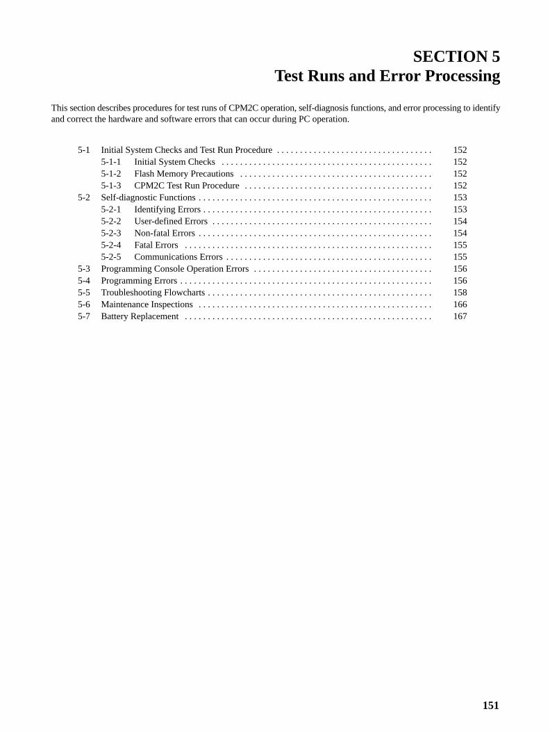
151
SECTION 5Test Runs and Error Processing
This section describes procedures for test runs of CPM2C operation, self-diagnosis functions, and error processing to identifyand correct the hardware and software errors that can occur during PC operation.
5-1 Initial System Checks and Test Run Procedure 152. . . . . . . . . . . . . . . . . . . . . . . . . . . . . . . . . . 5-1-1 Initial System Checks 152. . . . . . . . . . . . . . . . . . . . . . . . . . . . . . . . . . . . . . . . . . . . . . 5-1-2 Flash Memory Precautions 152. . . . . . . . . . . . . . . . . . . . . . . . . . . . . . . . . . . . . . . . . . 5-1-3 CPM2C Test Run Procedure 152. . . . . . . . . . . . . . . . . . . . . . . . . . . . . . . . . . . . . . . . .
5-2 Self-diagnostic Functions 153. . . . . . . . . . . . . . . . . . . . . . . . . . . . . . . . . . . . . . . . . . . . . . . . . . . 5-2-1 Identifying Errors 153. . . . . . . . . . . . . . . . . . . . . . . . . . . . . . . . . . . . . . . . . . . . . . . . . . 5-2-2 User-defined Errors 154. . . . . . . . . . . . . . . . . . . . . . . . . . . . . . . . . . . . . . . . . . . . . . . . 5-2-3 Non-fatal Errors 154. . . . . . . . . . . . . . . . . . . . . . . . . . . . . . . . . . . . . . . . . . . . . . . . . . . 5-2-4 Fatal Errors 155. . . . . . . . . . . . . . . . . . . . . . . . . . . . . . . . . . . . . . . . . . . . . . . . . . . . . . 5-2-5 Communications Errors 155. . . . . . . . . . . . . . . . . . . . . . . . . . . . . . . . . . . . . . . . . . . . .
5-3 Programming Console Operation Errors 156. . . . . . . . . . . . . . . . . . . . . . . . . . . . . . . . . . . . . . . 5-4 Programming Errors 156. . . . . . . . . . . . . . . . . . . . . . . . . . . . . . . . . . . . . . . . . . . . . . . . . . . . . . . 5-5 Troubleshooting Flowcharts 158. . . . . . . . . . . . . . . . . . . . . . . . . . . . . . . . . . . . . . . . . . . . . . . . . 5-6 Maintenance Inspections 166. . . . . . . . . . . . . . . . . . . . . . . . . . . . . . . . . . . . . . . . . . . . . . . . . . . 5-7 Battery Replacement 167. . . . . . . . . . . . . . . . . . . . . . . . . . . . . . . . . . . . . . . . . . . . . . . . . . . . . .
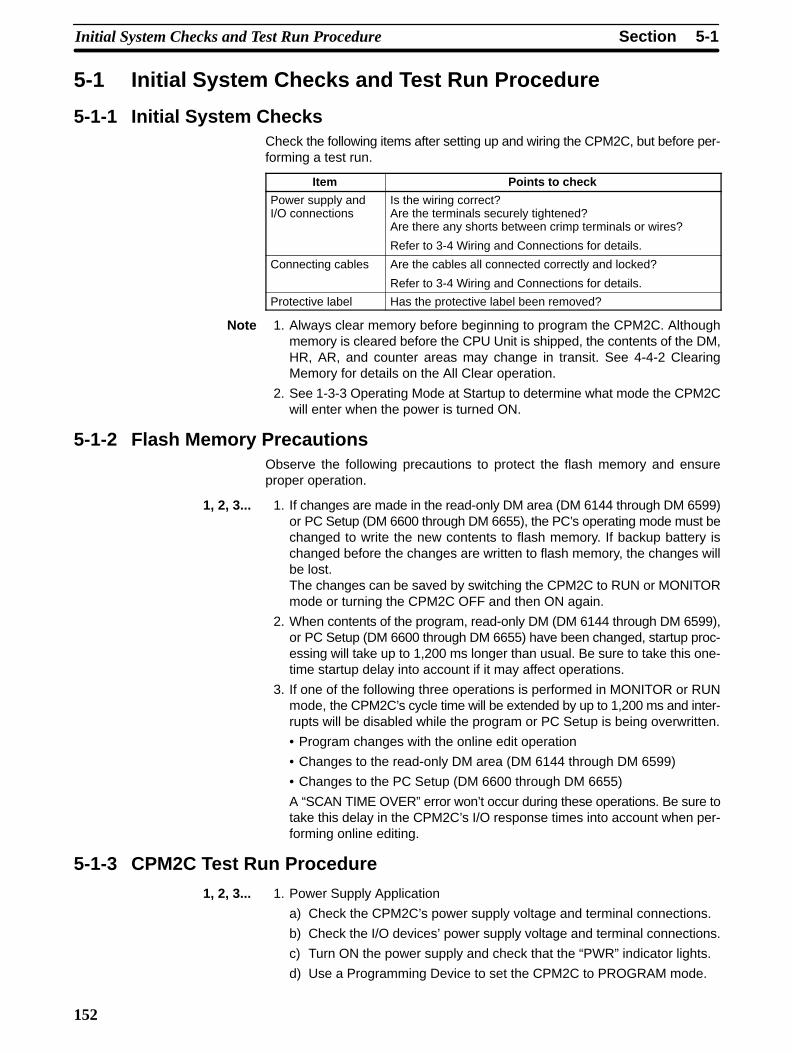
5-1SectionInitial System Checks and Test Run Procedure
152
5-1 Initial System Checks and Test Run Procedure
5-1-1 Initial System ChecksCheck the following items after setting up and wiring the CPM2C, but before per-forming a test run.
Item Points to check
Power supply andI/O connections
Is the wiring correct?Are the terminals securely tightened?Are there any shorts between crimp terminals or wires?
Refer to 3-4 Wiring and Connections for details.
Connecting cables Are the cables all connected correctly and locked?
Refer to 3-4 Wiring and Connections for details.
Protective label Has the protective label been removed?
Note 1. Always clear memory before beginning to program the CPM2C. Althoughmemory is cleared before the CPU Unit is shipped, the contents of the DM,HR, AR, and counter areas may change in transit. See 4-4-2 ClearingMemory for details on the All Clear operation.
2. See 1-3-3 Operating Mode at Startup to determine what mode the CPM2Cwill enter when the power is turned ON.
5-1-2 Flash Memory PrecautionsObserve the following precautions to protect the flash memory and ensureproper operation.
1, 2, 3... 1. If changes are made in the read-only DM area (DM 6144 through DM 6599)or PC Setup (DM 6600 through DM 6655), the PC’s operating mode must bechanged to write the new contents to flash memory. If backup battery ischanged before the changes are written to flash memory, the changes willbe lost.The changes can be saved by switching the CPM2C to RUN or MONITORmode or turning the CPM2C OFF and then ON again.
2. When contents of the program, read-only DM (DM 6144 through DM 6599),or PC Setup (DM 6600 through DM 6655) have been changed, startup proc-essing will take up to 1,200 ms longer than usual. Be sure to take this one-time startup delay into account if it may affect operations.
3. If one of the following three operations is performed in MONITOR or RUNmode, the CPM2C’s cycle time will be extended by up to 1,200 ms and inter-rupts will be disabled while the program or PC Setup is being overwritten.
• Program changes with the online edit operation
• Changes to the read-only DM area (DM 6144 through DM 6599)
• Changes to the PC Setup (DM 6600 through DM 6655)
A “SCAN TIME OVER” error won’t occur during these operations. Be sure totake this delay in the CPM2C’s I/O response times into account when per-forming online editing.
5-1-3 CPM2C Test Run Procedure
1, 2, 3... 1. Power Supply Application
a) Check the CPM2C’s power supply voltage and terminal connections.
b) Check the I/O devices’ power supply voltage and terminal connections.
c) Turn ON the power supply and check that the “PWR” indicator lights.
d) Use a Programming Device to set the CPM2C to PROGRAM mode.

!
5-2SectionSelf-diagnostic Functions
153
2. I/O Wiring Checks
a) With the CPM2C in PROGRAM mode, check the output wiring by turningON the output bits with the force set and force reset operations.Refer to 4-4-24 Force Set, Reset for details.
b) Check the input wiring with the CPM2C’s input indicators or a Program-ming Device’s monitor operations.
3. Test Run
a) Use a Programming Device to set the CPM2C to RUN or MONITORmode and check that the “RUN” indicator lights.
b) Check the sequence of operation with the force set/reset operations, etc.
4. Debugging
Correct any programming errors that are detected.
5. Saving the Program
a) Use a Programming Device to write the program to a backup floppy disk.
b) Print out a hard copy of the program with a printer.
Note Refer to Section 4 Using Programming Devices for details on the Support Soft-ware and Programming Console operations.
5-2 Self-diagnostic FunctionsThe CPM2C is equipped with a variety of self-diagnostic functions to help iden-tify and correct errors and reduce down time.
5-2-1 Identifying ErrorsAn error can be identified by the error message displayed on a ProgrammingDevice, error flags in the AR and SR areas, and the error code output to SR 253.
PC errors are divided into 2 categories based on the severity of the errors. Thestatus of the ERR/ALM indicator (lit or flashing) shows which type of error hasoccurred.
ERR/ALM Lit (Fatal Error)Fatal errors are serious errors which stop CPM2C operation. There are twoways to restart operation:
• Turn the PC OFF and then ON again.
• Use a Programming Device to switch the PC to PROGRAM mode, and read/clear the error.
ERR/ALM Flashing (Non-fatal Error)Non-fatal errors are less serious errors which don’t stop CPM2C operation.
When an error is detected, a corresponding error message will be displayed onthe Programming Console or other Programming Device connected to the PC.
When a hardware error is detected, the corresponding error flag in the AR or SRarea will be turned ON.
When an error is detected, a specific 2-digit hexadecimal error code is output toSR 25300 to SR 25307. The error code and time of occurrence are also output tothe Error Log Area (DM 2000 to DM 2021).
WARNING Emergency stop circuits, interlock circuits, limit circuits, and similar safetymeasures must be provided in external control circuits (i.e., not in theProgrammable Controller) to ensure safety in the system if an abnormalityoccurs due to malfunction of the PC or another external factor affecting the PCoperation. Not providing proper safety measures may result in seriousaccidents.
Fatal and Non-fatalErrors
Error Messages
Error Flags
Error Code

!
5-2SectionSelf-diagnostic Functions
154
WARNING The PC will turn OFF all outputs when its self-diagnosis function detects anyerror or when a severe failure alarm (FALS) instruction is executed. Externalsafety measures must be provided to ensure safety in the system. Not providingproper safety measures may result in serious accidents.
5-2-2 User-defined ErrorsThere are three instructions that can be used to define errors or messages.FAL(06) causes a non-fatal error, FAL(07) causes a fatal error, and MSG(46)sends a message to the Programming Console or host computer connected tothe PC.
FAL(06) is an instruction that causes a non-fatal error. The following will occurwhen an FAL(06) instruction is executed:
1, 2, 3... 1. The ERR/ALM indicator on the CPU Unit will flash. PC operation will con-tinue.
2. The instruction’s 2-digit BCD FAL number (01 to 99) will be written toSR 25300 to SR 25307.
The FAL numbers can be set arbitrarily to indicate particular conditions, but thesame number should not be used as both an FAL number and an FALS number.To clear an FAL error, correct the cause of the error and then execute FAL 00 oruse a Programming Device to clear the error.
FALS(07) is an instruction that causes a fatal error. The following will occur whenan FALS(07) instruction is executed:
1, 2, 3... 1. Program execution will be stopped and all outputs will be turned OFF.2. The ERR/ALM indicator on the CPU Unit will be lit.3. The instruction’s 2-digit BCD FALS number (01 to 99) will be written to
SR 25300 to SR 25307.The FALS numbers can be set arbitrarily to indicate particular conditions, but thesame number should not be used as both an FAL number and an FALS number.To clear an FALS error, use a Programming Device to switch the PC to PRO-GRAM Mode, correct the cause of the error, and then clear the error.
MSG(46) is used to display a message on a Programming Device connected tothe CPM2C. The message, which can be up to 16 characters long, is displayedwhen the instruction’s execution condition is ON.
5-2-3 Non-fatal ErrorsPC operation and program execution will continue after one or more of theseerrors have occurred. Although PC operation will continue, the cause of the errorshould be corrected and the error cleared as soon as possible.When one of these errors occurs, the POWER and RUN indicators will remain litand the ERR/ALM indicator will flash.
Message FAL No. Meaning and appropriate responseSYS FAIL FAL**(** is 01 to 99 or 9B.)
01 to 99 An FAL(06) instruction has been executed in the program. Check the FAL number todetermine conditions that would cause execution, correct the cause, and clear theerror.
9B An error has been detected in the PC Setup. Check flags AR 1300 to AR 1302, andcorrect as directed.
AR 1300 ON: An incorrect setting was detected in the PC Setup (DM 6600 toDM 6614) when power was turned ON. Correct the settings in PROGRAM Mode andturn ON the power again.
AR 1301 ON: An incorrect setting was detected in the PC Setup (DM 6615 toDM 6644) when switching to RUN or MONITOR mode. Correct the settings inPROGRAM Mode and switch to RUN or MONITOR mode again.
AR 1302 ON: An incorrect setting was detected in the PC Setup (DM 6645 toDM 6655) during operation. Correct the settings and clear the error.
FAILURE ALARM –FAL(06)
SEVERE FAILURE ALARM –FALS(07)
MESSAGE – MSG(46)

5-2SectionSelf-diagnostic Functions
155
Message Meaning and appropriate responseFAL No.
SCAN TIME OVER F8 The cycle time has exceeded 100 ms. (SR 25309 will be ON.)
This indicates that the program cycle time is longer than recommended. Reduce cycletime if possible. (The CPM2C can be set so that this error won’t be detected.)
Battery error(no message)
F7 If the Low Battery Detection Switch is ON and the voltage of the CPM2C-BAT01backup battery is below the minimum level, the ERR/ALM indicator will flash and SR25308 will be turned ON. (See page 42 for details on the Low Battery DetectionSwitch.)Replace the battery. (See 5-7 Battery Replacement for details.)
5-2-4 Fatal Errors
PC operation and program execution will stop and all outputs from the PC will beturned OFF when any of these errors have occurred. CPM2C operation can’t berestarted until the PC is turned OFF and then ON again or a Programming De-vice is used to switch the PC to PROGRAM mode and clear the fatal error.
All CPU Unit indicators will be OFF for the power interruption error. For all otherfatal operating errors, the POWER and ERR/ALM indicators will be lit. The RUNindicator will be OFF.
Message FALSNo.
Meaning and appropriate response
Power interruption(no message)
None Power has been interrupted for more than 10 ms (2 ms for DC power types.)Check power supply voltage and power lines. Try to power-up again.
MEMORY ERR F1 AR 1308 ON: There is a non-existent bit or word address in the user program. Checkthe program and correct errors.
AR 1309 ON: An error has occurred in flash memory. Replace the CPU Unit.
AR 1310 ON: A checksum error has occurred in read-only DM (DM 6144 to DM 6599).Check and correct the settings in the read-only DM area.
AR 1311 ON: A checksum error has occurred in the PC Setup. Initialize the PC Setupand input the settings again.
AR 1312 ON: A checksum error has occurred in the program. Check the program andcorrect any errors detected.
AR 1313 ON: A checksum error has occurred in the expansion instructions data and allfunction codes have been set the their default values. Reset the expansioninstructions.
AR 1314 ON: Data was not maintained in an area specified for holding. Clear the error,check the data in the areas specified for holding, and try again.
NO END INST F0 END(01) is not written in the program. Write END(01) at the end of the program.
I/O BUS ERR C0 An error has occurred during data transfer between the CPU Unit and an ExpansionI/O Unit or Expansion Unit. Check the Unit’s connecting cable.
I/O UNIT OVER E1 Too many Expansion Units or Expansion I/O Units have been connected. Check theUnit configuration.
SYS FAIL FALS**(** is 01 to 99 or 9F.)
01 to 99 A FALS(07) instruction has been executed in the program. Check the FALS number todetermine the conditions that caused execution, correct the cause, and clear the error.
9F The cycle time has exceeded the Maximum (Watch) Cycle Time setting (DM 6618).Check the cycle time and adjust the Maximum Cycle Time setting if necessary.
5-2-5 Communications Errors
The COMM indicator will be turned OFF and AR 0812 will be turned ON if anerror occurs in communications through the peripheral port or AR 0804 will beturned ON if an error occurs in communications through the RS-232C port.Check the connecting cables and restart.
There are no error messages or error codes generated by this error and theERR/ALM indicator is not affected.

5-4SectionProgramming Errors
156
5-3 Programming Console Operation ErrorsThe following error messages may appear when performing operations on theProgramming Console. Correct the error as indicated and continue operation.
Message Meaning and appropriate response
REPL ROM An attempt was made to write to write-protected memory. Set bits00 to 03 of DM 6602 to “0.”
PROG OVER The instruction at the last address in memory is not NOP(00). Eraseall unnecessary instructions after END(01).
ADDR OVER An address was set that is larger than the highest memory addressin Program Memory. Input a smaller address.
SETDATAERR
FALS 00 has been input, and “00” cannot be input. Reinput thedata.
I/O NO. ERR A data area address has been designated that exceeds the limit ofthe data area, e.g., an address is too large. Confirm therequirements for the instruction and re-enter the address.
Note Refer to the relevant Support Software Operation Manual for details on errorsthat may appear when operating the SSS or SYSMAC-CPT Support Software.
5-4 Programming ErrorsThese errors in program syntax will be detected when the program is checkedusing the Program Check operation.
Three levels of program checking are available. The desired level must be des-ignated to indicate the type of errors that are to be detected. The following tableprovides the error types, displays, and explanations of all syntax errors. Checklevel 0 checks for type A, B, and C errors; check level 1, for type A and B errors;and check level 2, for type A errors only.
Type Message Meaning and appropriate responseA ???? The program has been damaged, creating a non-existent
function code. Re-enter the program.
CIRCUIT ERR The number of LD instructions (LD or LD NOT) does notmatch the number of logic block instructions (OR LD orAND LD).Check your program.
OPERANDERR
A constant entered for the instruction is not within definedvalues. Change the constant so that it lies within theproper range.
NO ENDINSTR
There is no END(01) in the program. Write END(01) at theend of the program.
LOCN ERR An instruction is in the wrong place in the program. Checkinstruction requirements and correct the program.
JME UNDEFD A JME(05) instruction is missing for a JMP(04) instruction.Correct the jump number or insert the proper JME(05)instruction.
DUPL The same jump number or subroutine number has beenused twice. Correct the program so that the same numberis only used once for each.
SBN UNDEFD An SBN(92) has not been programmed with the samesubroutine number as an SBS(91) instruction in theprogram. Correct the program.
STEP ERR STEP(08) with a section number and STEP(08) without asection number have been used incorrectly. CheckSTEP(08) programming requirements and correct theprogram.

5-4SectionProgramming Errors
157
Type Meaning and appropriate responseMessageB IL-ILC ERR IL(02) and ILC(03) are not used in pairs. Correct the
program so that each IL(02) has a unique ILC(03).Although this error message will appear if more than oneIL(02) is used with the same ILC(03), the program willexecuted as written. Make sure your program is written asdesired before proceeding.
JMP-JME ERR JMP(04) and JME(05) are not used in pairs. Make sureyour program is written as desired before proceeding.
SBN-RET ERR RET(93) has not been used properly or the relationshipbetween SBN(92) and RET(93) is not correct. Correct theprogram.
C COIL DUPL The same bit is being controlled (i.e., turned ON and/orOFF) by more than one instruction (e.g., OUT, OUT NOT,DIFU(13), DIFD(14), KEEP(11), SFT(10)). Although this isallowed for certain instructions, check instructionrequirements to confirm that the program is correct orrewrite the program so that each bit is controlled by onlyone instruction.
JMP UNDEFD JME(05) has been used with no JMP(04) with the samejump number. Add a JMP(04) with the same number ordelete the JME(05) that is not being used.
SBS UNDEFD A subroutine exists that is not called by SBS(91). Programa subroutine call in the proper place, or delete thesubroutine if it is not required.

5-5SectionTroubleshooting Flowcharts
158
5-5 Troubleshooting FlowchartsUse the following flowcharts to troubleshoot errors that occur during operation.
Main Check
Check for non-fatal errors. (See page 161.)
Error
Replace the CPUUnit.
PWR indicator lit?
RUN indicator lit?
ERR/ALM indicatorflashing?
Is I/O sequencenormal?
Operating environment normal?
Operation stopped. Check for fatal errors. (See page 160.)
Check I/O. (See page 162.)
Check operating environment. (See page 164.)
Yes
Check power supply. (See page 159.)No
No
No
No
Flashing
Yes
Yes
Not lit
Yes

5-5SectionTroubleshooting Flowcharts
159
Power Supply Check
PWR indicator not lit.
Replace the CPUUnit.
Is power beingsupplied?
Is voltage adequate?
Are there any discon-nected connectors or
broken wires?
Connect powersupply.
Is PWR indicator lit?
Set supply voltagewithin acceptable limits.
Is PWR indicator lit?
Connect connectorsor replace wires.
End
Yes
No
No Yes
YesNo
No
NoIs PWR indicator lit?
Yes
No
Yes
Yes

5-5SectionTroubleshooting Flowcharts
160
Fatal Error Check
Identify the error, eliminateits cause, and clear theerror.Follow the Memory ErrorCheck flowchart if amemory error has occurred.
Is the ERR/ALMindicator lit?
Determine the causeof the error with aProgramming Device.
End
RUN indicator not lit.
Replace the CPUUnit.
Is PC mode displayedon Programming
Device?
Turn the powersupply OFF, andthen ON again.
Switch to RUN orMONITOR mode.
No
Yes
Is a fatal errordisplayed?
Is PC mode displayed onProgramming Device?
No
Yes
Yes
No
Is the RUNindicator lit?
No
Yes
Yes
No
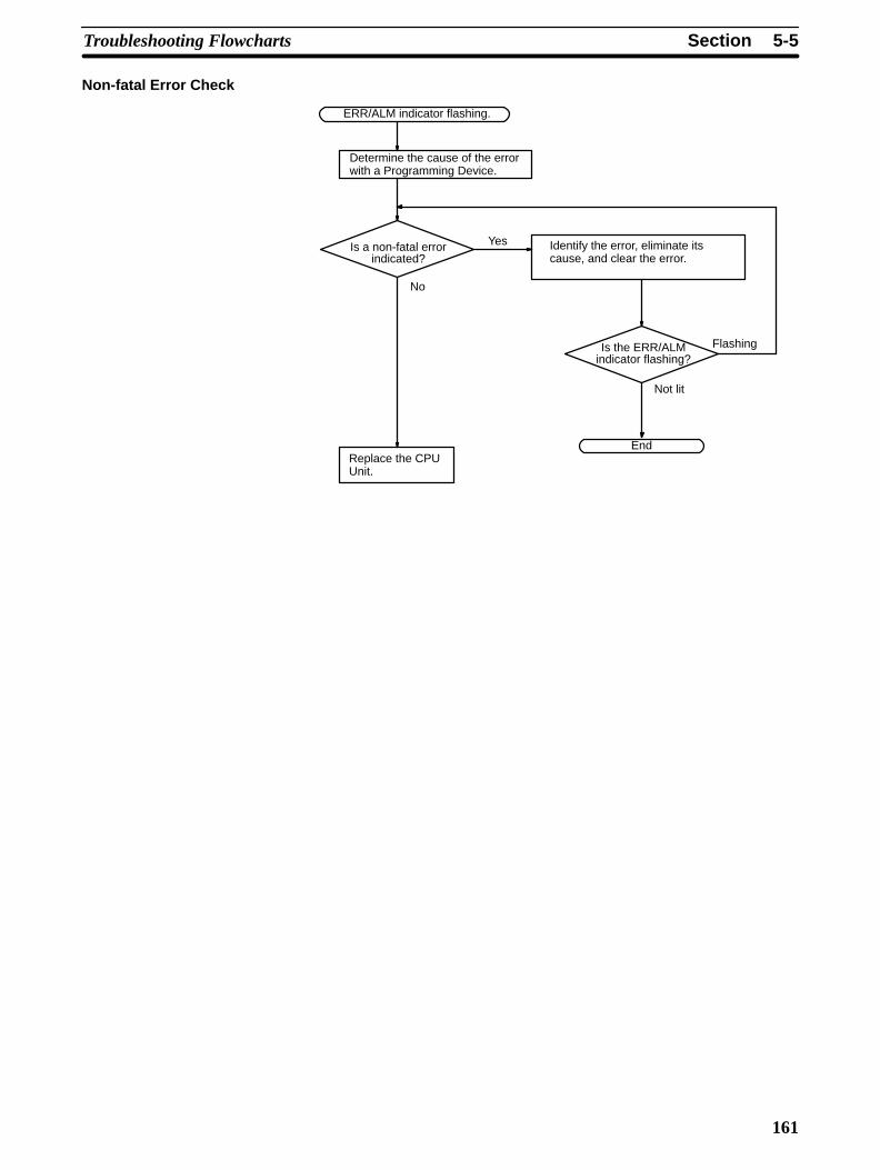
5-5SectionTroubleshooting Flowcharts
161
Non-fatal Error Check
Identify the error, eliminate itscause, and clear the error.
ERR/ALM indicator flashing.
Is a non-fatal errorindicated?
Is the ERR/ALMindicator flashing?
Replace the CPUUnit.
End
Determine the cause of the errorwith a Programming Device.
No
Yes
Flashing
Not lit

5-5SectionTroubleshooting Flowcharts
162
The I/O check flowchart is based on the following ladder diagram section.
01003
00002(LS1)
00003(LS2)
SOL1 malfunction.
SOL1
01003
Yes
Monitor the ON/OFFstatus of IR 01003with a ProgrammingDevice.
NoIs theIR 01003 output indicator
operating normally?
Check the voltage at theIR 01003 terminals.
Wire correctly.
Operation OK? Is output wiringcorrect?
Disconnect the external wiresand check the conductivity ofeach wire.
No
Check output deviceSOL1.
Operation OK?
Replace the CPU Unit Ex-pansion Unit, or ExpansionI/O Unit with the problem.
Yes
No No
Operation OK? NoYes
Yes
ATonextpage
Malfunction of SOL1
Yes
I/O Check

5-5SectionTroubleshooting Flowcharts
163
Yes
No
Check the voltage atthe IR 00002 andIR 00003 terminals.
Check operation by using adummy input signal to turn theinput ON and OFF.
No
Replace the CPU Unit,Expansion Unit, orExpansion I/O Unit.
Are the terminalscrews loose or con-
nectors disconnected?
Operation OK?
Wire correctly.
Is input wiringcorrect?
Tighten the terminalscrews and connectconnectors.
Check input devicesLS1 and LS2.
Return to “start.”
Are the IR 00002and IR 00003 input indi-
cators operatingnormally?
Operation OK?
Replace the CPU Unit,Expansion Unit, orExpansion I/O Unit.
Operation OK?
Yes
Yes
Yes
Yes
NoNo
No
No
No
No
No
Check the voltage atthe IR 00002 andIR 00003 terminals.
AFrompreviouspage
Yes
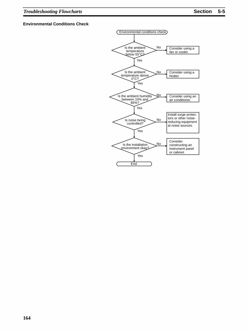
5-5SectionTroubleshooting Flowcharts
164
Environmental Conditions Check
Consider using afan or cooler.
Is the ambienttemperaturebelow 55°C?
Is the ambienttemperature above
0°C?
Is noise beingcontrolled?
Is the installationenvironment okay?
Consider using aheater.
Consider using anair conditioner.
Install surge protec-tors or other noise-reducing equipmentat noise sources.
Considerconstructing aninstrument panelor cabinet.
End.
Yes
No
Yes
No
No
No
No
Yes
Yes
Yes
Is the ambient humiditybetween 10% and
85%?
Environmental conditions check

5-5SectionTroubleshooting Flowcharts
165
Memory Error Check
Memory error occurred.
AR 1309 ON?
AR 1314 ON?
AR 1308 ON?
Replace the CPUUnit.
Check/correct backed-up data andclear error.
Check the program, correct anyerrors, and clear the error.
End
No
Yes
No
No
Yes
No
Yes
AR 1310 toAR 1312 ON?
Check the error indicated bythe flag that is ON, correct set-tings as required, and writedata to the flash memory.
No
Turned ON during startup?
YesYes
Check the externalenvironment.
No
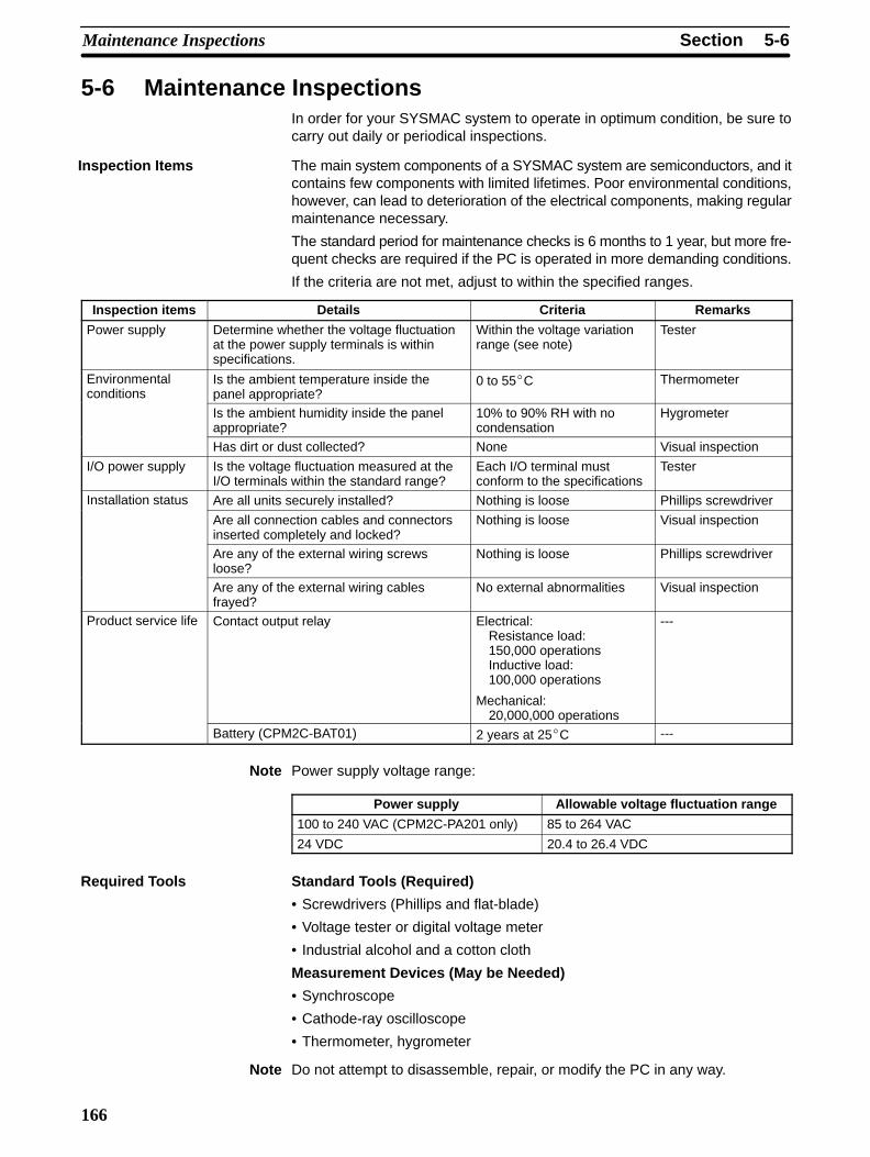
5-6SectionMaintenance Inspections
166
5-6 Maintenance InspectionsIn order for your SYSMAC system to operate in optimum condition, be sure tocarry out daily or periodical inspections.
The main system components of a SYSMAC system are semiconductors, and itcontains few components with limited lifetimes. Poor environmental conditions,however, can lead to deterioration of the electrical components, making regularmaintenance necessary.
The standard period for maintenance checks is 6 months to 1 year, but more fre-quent checks are required if the PC is operated in more demanding conditions.
If the criteria are not met, adjust to within the specified ranges.
Inspection items Details Criteria Remarks
Power supply Determine whether the voltage fluctuationat the power supply terminals is withinspecifications.
Within the voltage variationrange (see note)
Tester
Environmentalconditions
Is the ambient temperature inside thepanel appropriate?
0 to 55C Thermometer
Is the ambient humidity inside the panelappropriate?
10% to 90% RH with nocondensation
Hygrometer
Has dirt or dust collected? None Visual inspection
I/O power supply Is the voltage fluctuation measured at theI/O terminals within the standard range?
Each I/O terminal mustconform to the specifications
Tester
Installation status Are all units securely installed? Nothing is loose Phillips screwdriver
Are all connection cables and connectorsinserted completely and locked?
Nothing is loose Visual inspection
Are any of the external wiring screwsloose?
Nothing is loose Phillips screwdriver
Are any of the external wiring cablesfrayed?
No external abnormalities Visual inspection
Product service life Contact output relay Electrical: Resistance load:150,000 operationsInductive load:100,000 operations
Mechanical: 20,000,000 operations
---
Battery (CPM2C-BAT01) 2 years at 25C ---
Note Power supply voltage range:
Power supply Allowable voltage fluctuation range
100 to 240 VAC (CPM2C-PA201 only) 85 to 264 VAC
24 VDC 20.4 to 26.4 VDC
Standard Tools (Required)
• Screwdrivers (Phillips and flat-blade)
• Voltage tester or digital voltage meter
• Industrial alcohol and a cotton cloth
Measurement Devices (May be Needed)
• Synchroscope
• Cathode-ray oscilloscope
• Thermometer, hygrometer
Note Do not attempt to disassemble, repair, or modify the PC in any way.
Inspection Items
Required Tools
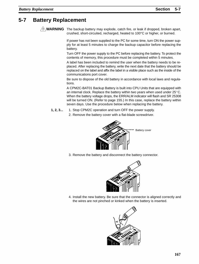
!
5-7SectionBattery Replacement
167
5-7 Battery Replacement
WARNING The backup battery may explode, catch fire, or leak if dropped, broken apart,crushed, short-circuited, recharged, heated to 100°C or higher, or burned.
If power has not been supplied to the PC for some time, turn ON the power sup-ply for at least 5 minutes to charge the backup capacitor before replacing thebattery.Turn OFF the power supply to the PC before replacing the battery. To protect thecontents of memory, this procedure must be completed within 5 minutes.A label has been included to remind the user when the battery needs to be re-placed. After replacing the battery, write the next date that the battery should bereplaced on the label and affix the label in a visible place such as the inside of thecommunications port cover.
Be sure to dispose of the old battery in accordance with local laws and regula-tions.
A CPM2C-BAT01 Backup Battery is built into CPU Units that are equipped withan internal clock. Replace the battery within two years when used under 25C.When the battery voltage drops, the ERR/ALM indicator will flash and SR 25308will be turned ON. (Refer to page 155.) In this case, replace the battery withinseven days. Use the procedure below when replacing the battery.
1, 2, 3... 1. Stop CPM2C operation and turn OFF the power supply.2. Remove the battery cover with a flat-blade screwdriver.
Battery cover
3. Remove the battery and disconnect the battery connector.
4. Install the new battery. Be sure that the connector is aligned correctly andthe wires are not pinched or kinked when the battery is inserted.

5-7SectionBattery Replacement
168
5. To enable the detection of low battery errors, slide the Low Battery DetectionSwitch towards the front of the Unit and set bits 12 to 15 of DM 6655 to “0.”
Low Battery Detection Switch
Enable
6. Replace the battery cover.
7. Write the next date that the battery should be replaced on the reminder label.The battery lifetime of the CPU Unit with clock is 2 years at 25C and that ofthe CPU Unit without clock is 5 years at 25°C.

169
SECTION 6Expansion Memory Unit
This section describes how to use the CPM1-EMU01-V1 Expansion Memory Unit. Follow the handling precautions and pro-cedures to properly use the Unit.
6-1 Overview 170. . . . . . . . . . . . . . . . . . . . . . . . . . . . . . . . . . . . . . . . . . . . . . . . . . . . . . . . . . . . . . . 6-1-1 Memory Areas 170. . . . . . . . . . . . . . . . . . . . . . . . . . . . . . . . . . . . . . . . . . . . . . . . . . . . 6-1-2 Precautions 170. . . . . . . . . . . . . . . . . . . . . . . . . . . . . . . . . . . . . . . . . . . . . . . . . . . . . . .
6-2 Specifications and Nomenclature 171. . . . . . . . . . . . . . . . . . . . . . . . . . . . . . . . . . . . . . . . . . . . . 6-2-1 Specifications 171. . . . . . . . . . . . . . . . . . . . . . . . . . . . . . . . . . . . . . . . . . . . . . . . . . . . . 6-2-2 Nomenclature 171. . . . . . . . . . . . . . . . . . . . . . . . . . . . . . . . . . . . . . . . . . . . . . . . . . . . .
6-3 Handling 172. . . . . . . . . . . . . . . . . . . . . . . . . . . . . . . . . . . . . . . . . . . . . . . . . . . . . . . . . . . . . . . . 6-3-1 Mounting/Removing EEPROM 172. . . . . . . . . . . . . . . . . . . . . . . . . . . . . . . . . . . . . . . 6-3-2 PC Connections 173. . . . . . . . . . . . . . . . . . . . . . . . . . . . . . . . . . . . . . . . . . . . . . . . . . . 6-3-3 Uploading Programs 174. . . . . . . . . . . . . . . . . . . . . . . . . . . . . . . . . . . . . . . . . . . . . . . 6-3-4 Downloading Programs 175. . . . . . . . . . . . . . . . . . . . . . . . . . . . . . . . . . . . . . . . . . . . .
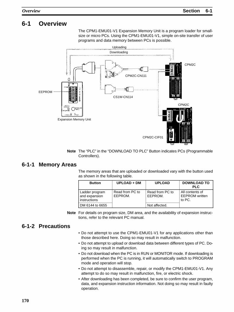
6-1SectionOverview
170
6-1 OverviewThe CPM1-EMU01-V1 Expansion Memory Unit is a program loader for small-size or micro PCs. Using the CPM1-EMU01-V1, simple on-site transfer of userprograms and data memory between PCs is possible.
Uploading
Downloading
Expansion Memory Unit
EEPROM
CPM2C-CN111
CS1W-CN114
CPM2C
CPM2C
CPM2C-CIF01
Note The “PLC” in the “DOWNLOAD TO PLC” Button indicates PCs (ProgrammableControllers).
6-1-1 Memory AreasThe memory areas that are uploaded or downloaded vary with the button usedas shown in the following table.
Button UPLOAD + DM UPLOAD DOWNLOAD TOPLC
Ladder programand expansioninstructions
Read from PC toEEPROM.
Read from PC toEEPROM.
All contents ofEEPROM writtento PC.
DM 6144 to 6655 Not affected.
Note For details on program size, DM area, and the availability of expansion instruc-tions, refer to the relevant PC manual.
6-1-2 Precautions• Do not attempt to use the CPM1-EMU01-V1 for any applications other than
those described here. Doing so may result in malfunction.• Do not attempt to upload or download data between different types of PC. Do-
ing so may result in malfunction.• Do not download when the PC is in RUN or MONITOR mode. If downloading is
performed when the PC is running, it will automatically switch to PROGRAMmode and operation will stop.
• Do not attempt to disassemble, repair, or modify the CPM1-EMU01-V1. Anyattempt to do so may result in malfunction, fire, or electric shock.
• After downloading has been completed, be sure to confirm the user program,data, and expansion instruction information. Not doing so may result in faultyoperation.
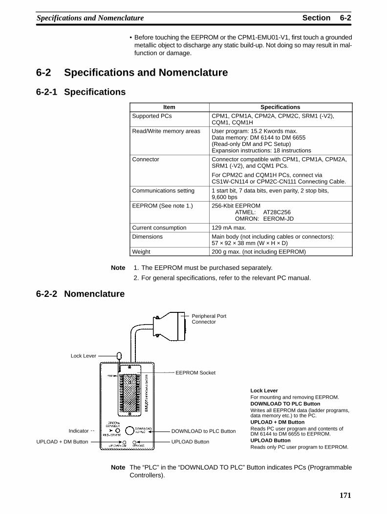
6-2SectionSpecifications and Nomenclature
171
• Before touching the EEPROM or the CPM1-EMU01-V1, first touch a groundedmetallic object to discharge any static build-up. Not doing so may result in mal-function or damage.
6-2 Specifications and Nomenclature
6-2-1 Specifications
Item Specifications
Supported PCs CPM1, CPM1A, CPM2A, CPM2C, SRM1 (-V2),CQM1, CQM1H
Read/Write memory areas User program: 15.2 Kwords max.Data memory: DM 6144 to DM 6655(Read-only DM and PC Setup)Expansion instructions: 18 instructions
Connector Connector compatible with CPM1, CPM1A, CPM2A,SRM1 (-V2), and CQM1 PCs.
For CPM2C and CQM1H PCs, connect viaCS1W-CN114 or CPM2C-CN111 Connecting Cable.
Communications setting 1 start bit, 7 data bits, even parity, 2 stop bits,9,600 bps
EEPROM (See note 1.) 256-Kbit EEPROMATMEL: AT28C256OMRON: EEROM-JD
Current consumption 129 mA max.
Dimensions Main body (not including cables or connectors):57 × 92 × 38 mm (W × H × D)
Weight 200 g max. (not including EEPROM)
Note 1. The EEPROM must be purchased separately.
2. For general specifications, refer to the relevant PC manual.
6-2-2 Nomenclature
Lock LeverFor mounting and removing EEPROM.DOWNLOAD TO PLC ButtonWrites all EEPROM data (ladder programs,data memory etc.) to the PC.UPLOAD + DM ButtonReads PC user program and contents ofDM 6144 to DM 6655 to EEPROM.UPLOAD ButtonReads only PC user program to EEPROM.
Lock Lever
Indicator
UPLOAD + DM Button
EEPROM Socket
DOWNLOAD to PLC Button
UPLOAD Button
Peripheral PortConnector
Note The “PLC” in the “DOWNLOAD TO PLC” Button indicates PCs (ProgrammableControllers).
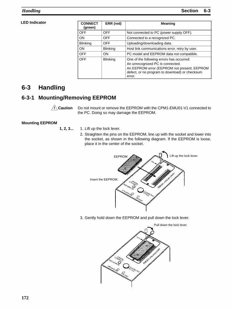
!
6-3SectionHandling
172
CONNECT(green)
ERR (red) Meaning
OFF OFF Not connected to PC (power supply OFF).
ON OFF Connected to a recognized PC.
Blinking OFF Uploading/downloading data.
ON Blinking Host link communications error, retry by user.
OFF ON PC model and EEPROM data not compatible.
OFF Blinking One of the following errors has occurred:An unrecognized PC is connected.An EEPROM error (EEPROM not present, EEPROMdefect, or no program to download) or checksumerror.
6-3 Handling
6-3-1 Mounting/Removing EEPROM
Caution Do not mount or remove the EEPROM with the CPM1-EMU01-V1 connected tothe PC. Doing so may damage the EEPROM.
Mounting EEPROM1, 2, 3... 1. Lift up the lock lever.
2. Straighten the pins on the EEPROM, line up with the socket and lower intothe socket, as shown in the following diagram. If the EEPROM is loose,place it in the center of the socket.
Lift up the lock lever.EEPROM
Insert the EEPROM.
3. Gently hold down the EEPROM and pull down the lock lever.
Pull down the lock lever.
LED Indicator
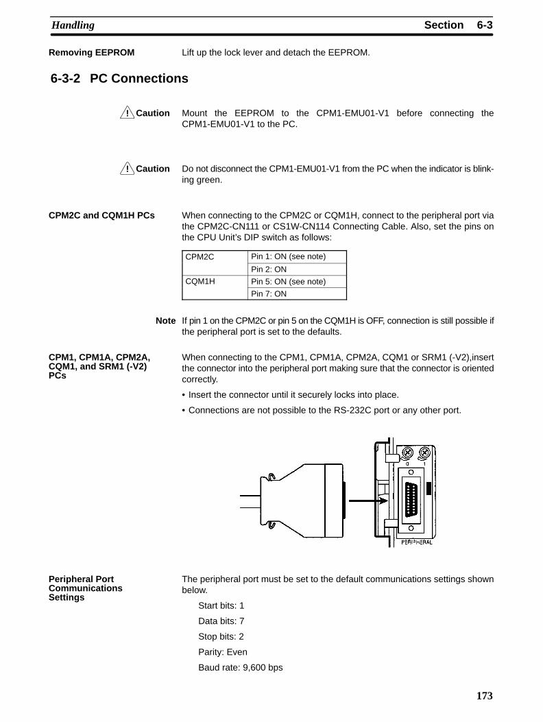
!
!
6-3SectionHandling
173
Lift up the lock lever and detach the EEPROM.
6-3-2 PC Connections
Caution Mount the EEPROM to the CPM1-EMU01-V1 before connecting theCPM1-EMU01-V1 to the PC.
Caution Do not disconnect the CPM1-EMU01-V1 from the PC when the indicator is blink-ing green.
When connecting to the CPM2C or CQM1H, connect to the peripheral port viathe CPM2C-CN111 or CS1W-CN114 Connecting Cable. Also, set the pins onthe CPU Unit’s DIP switch as follows:
CPM2C Pin 1: ON (see note)
Pin 2: ON
CQM1H Pin 5: ON (see note)
Pin 7: ON
Note If pin 1 on the CPM2C or pin 5 on the CQM1H is OFF, connection is still possible ifthe peripheral port is set to the defaults.
When connecting to the CPM1, CPM1A, CPM2A, CQM1 or SRM1 (-V2),insertthe connector into the peripheral port making sure that the connector is orientedcorrectly.
• Insert the connector until it securely locks into place.
• Connections are not possible to the RS-232C port or any other port.
The peripheral port must be set to the default communications settings shownbelow.
Start bits: 1
Data bits: 7
Stop bits: 2
Parity: Even
Baud rate: 9,600 bps
Removing EEPROM
CPM2C and CQM1H PCs
CPM1, CPM1A, CPM2A,CQM1, and SRM1 (-V2)PCs
Peripheral PortCommunicationsSettings
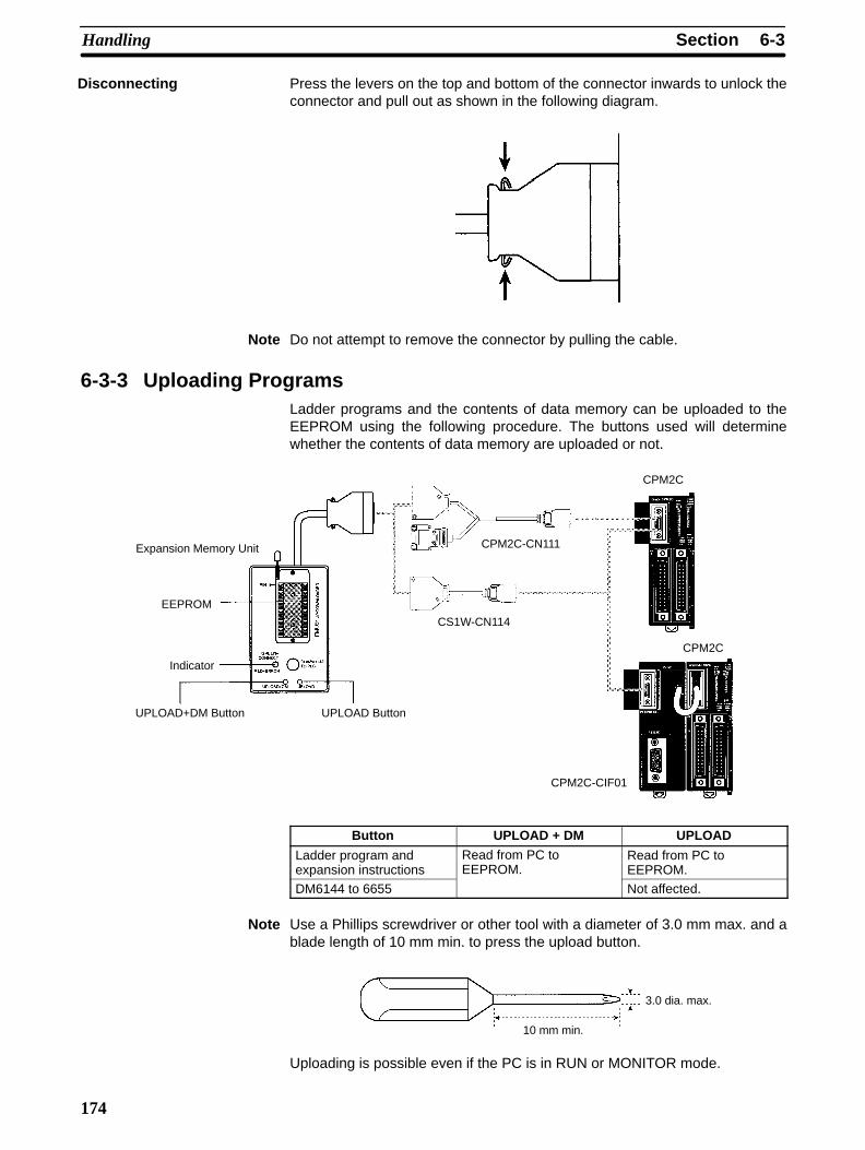
6-3SectionHandling
174
Press the levers on the top and bottom of the connector inwards to unlock theconnector and pull out as shown in the following diagram.
Note Do not attempt to remove the connector by pulling the cable.
6-3-3 Uploading ProgramsLadder programs and the contents of data memory can be uploaded to theEEPROM using the following procedure. The buttons used will determinewhether the contents of data memory are uploaded or not.
Expansion Memory Unit
Indicator
UPLOAD+DM Button UPLOAD Button
EEPROM
CPM2C-CN111
CS1W-CN114
CPM2C
CPM2C
CPM2C-CIF01
Button UPLOAD + DM UPLOAD
Ladder program andexpansion instructions
Read from PC toEEPROM.
Read from PC toEEPROM.
DM6144 to 6655 Not affected.
Note Use a Phillips screwdriver or other tool with a diameter of 3.0 mm max. and ablade length of 10 mm min. to press the upload button.
10 mm min.
3.0 dia. max.
Uploading is possible even if the PC is in RUN or MONITOR mode.
Disconnecting

6-3SectionHandling
175
Operation Procedure
Start
YesNo
Connect the CPM1-EMU01-V1 to the PC’scommunications port (peripheral port).
Mount the EEPROM to theCPM1-EMU01-V1.
After 2 or 3 s, check if the indicator islit green.
See the noteon the right.
Select the memory area to be uploaded.
Press the UPLOAD+DMButton.
Press the UPLOAD But-ton.
Check if the indicator is blinking green(indicating that uploading has started).
YesNo
See the note above.
Check if the indicator is lit green (in-dicating that uploading has been suc-cessfully completed).
YesNo
See the note above.
Remove the Expansion Memory Unitfrom the PC.
End
Mount the EEPROM to the CPM1-EMU01-V1before connecting to the PC.
Check the orientation of the connectorbefore connecting the CPM1-EMU01-V1.
Note If the indicator is not lit at all, lit red orblinks red, uploading will not be pos-sible. In this case, check the follow-ing items.
• Is the connector properly con-nected?
• Is the EEPROM properly mounted?
• Are the EEPROM specifications cor-rect?
• Are the peripheral port communica-tions settings correct?
Upload both the ladderprogram and DM 6144 toDM 6655.
Upload only the ladderprogram.
6-3-4 Downloading ProgramsLadder programs and the contents of data memory can be downloaded from theEEPROM to the PC using the procedure given below. When downloading, notethe following points.
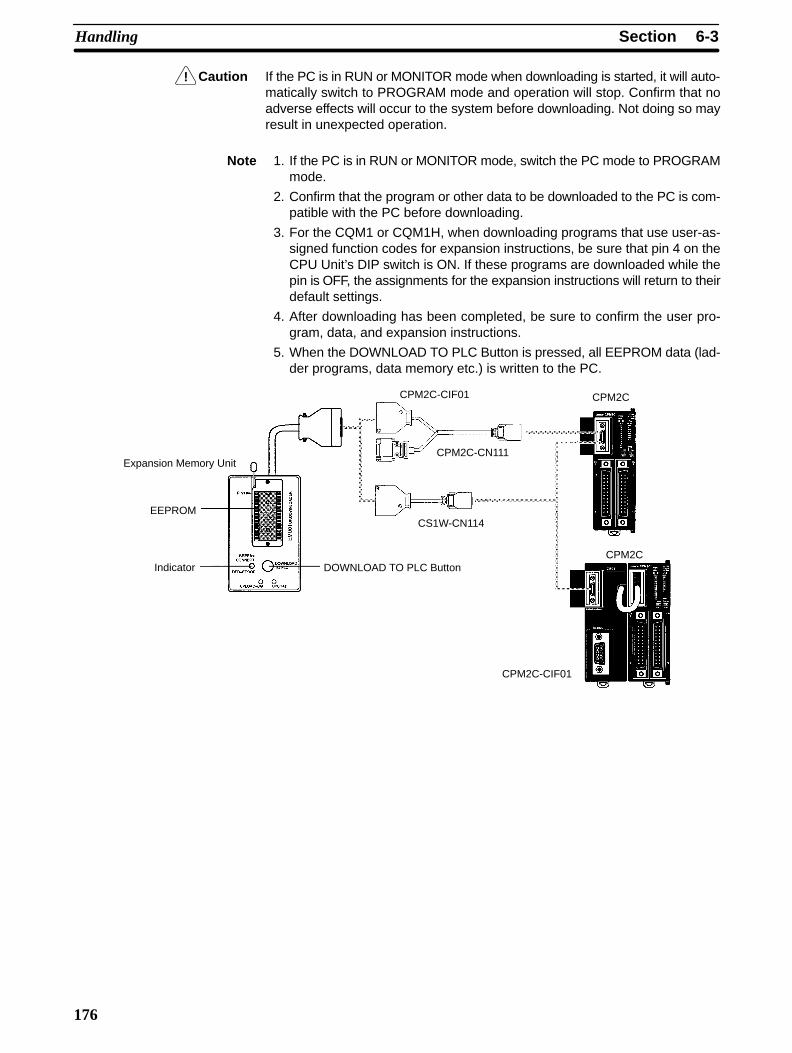
!
6-3SectionHandling
176
Caution If the PC is in RUN or MONITOR mode when downloading is started, it will auto-matically switch to PROGRAM mode and operation will stop. Confirm that noadverse effects will occur to the system before downloading. Not doing so mayresult in unexpected operation.
Note 1. If the PC is in RUN or MONITOR mode, switch the PC mode to PROGRAMmode.
2. Confirm that the program or other data to be downloaded to the PC is com-patible with the PC before downloading.
3. For the CQM1 or CQM1H, when downloading programs that use user-as-signed function codes for expansion instructions, be sure that pin 4 on theCPU Unit’s DIP switch is ON. If these programs are downloaded while thepin is OFF, the assignments for the expansion instructions will return to theirdefault settings.
4. After downloading has been completed, be sure to confirm the user pro-gram, data, and expansion instructions.
5. When the DOWNLOAD TO PLC Button is pressed, all EEPROM data (lad-der programs, data memory etc.) is written to the PC.
CPM2C-CIF01
Indicator DOWNLOAD TO PLC Button
Expansion Memory Unit
EEPROM
CPM2C-CN111
CS1W-CN114
CPM2C
CPM2C
CPM2C-CIF01

6-3SectionHandling
177
Operation Procedure
Start
YesNo
Change the mode of the PC to PRO-GRAM mode.
Mount the EEPROM to theCPM1-EMU01-V1.
After 2 or 3 s, check if the indicator islit green.
See the note onthe right.
Press the DOWNLOAD TO PLC But-ton.
Check if the indicator is blinkinggreen (indicating that downloadinghas started).
YesNo
See the note above.
Check if the indicator is lit green(indicating that downloading hasbeen successfully completed).
YesNo
See the note above.
Remove the Expansion Memory Unitfrom the PC.
End
Mount the EEPROM to theCPM1-EMU01-V1 before downloading.
Confirm the safety of the system.
Note If the indicator is not lit at all, lit red orblinks red, downloading will not bepossible. In this case, check the fol-lowing items.
• Is the connector properly con-nected?
• Is the EEPROM properly mounted?
• Are the EEPROM specifications cor-rect?
• Are the peripheral port communica-tions settings correct?
Connect the CPM1-EMU01-V1 to thePC’s peripheral port. Confirm the orientation of the connector
before connecting the CPM1-EMU01-V1.
Before actual operation, check the contentsof the ladder program and the DM area, aswell as the expansion instruction settings.
Check the program.

179
Appendix AStandard Models
CPU UnitsDescription Input Output Internal Model number
points points clock Relay outputs Transistor outputs
Sinking SourcingCPU Units withrelay outputs
6 points 4 points --- CPM2C-10CDR-D --- ---
Yes CPM2C-10C1DR-D --- ---
CPU Units withtransistor outputs
6 points 4 points --- --- CPM2C-10CDTC-D CPM2C-10CDT1C-D
Yes --- CPM2C-10C1DTC-D CPM2C-10C1DT1C-D
12 points 8 points --- --- CPM2C-20CDTC-D CPM2C-20CDT1C-D
Yes --- CPM2C-20C1DTC-D CPM2C-20C1DT1C-D
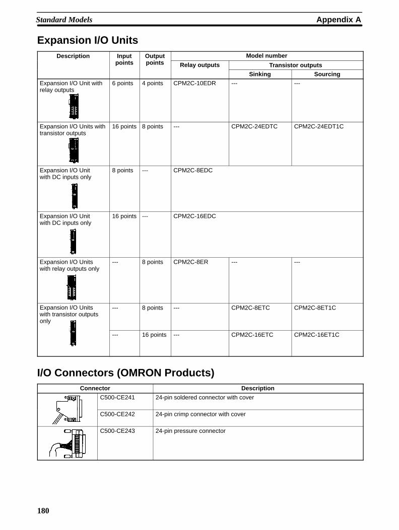
Appendix AStandard Models
180
Expansion I/O UnitsDescription Input Output Model number
points points Relay outputs Transistor outputs
Sinking Sourcing
Expansion I/O Unit withrelay outputs
6 points 4 points CPM2C-10EDR --- ---
Expansion I/O Units withtransistor outputs
16 points 8 points --- CPM2C-24EDTC CPM2C-24EDT1C
Expansion I/O Unitwith DC inputs only
8 points --- CPM2C-8EDC
Expansion I/O Unitwith DC inputs only
16 points --- CPM2C-16EDC
Expansion I/O Unitswith relay outputs only
--- 8 points CPM2C-8ER --- ---
Expansion I/O Unitswith transistor outputsonly
--- 8 points --- CPM2C-8ETC CPM2C-8ET1C
--- 16 points --- CPM2C-16ETC CPM2C-16ET1C
I/O Connectors (OMRON Products)Connector Description
C500-CE241 24-pin soldered connector with cover
C500-CE242 24-pin crimp connector with cover
C500-CE243 24-pin pressure connector

Appendix AStandard Models
181
Expansion Units
Analog I/O UnitModel Name Specifications
CPM2C-MAD11 Analog I/O Unit 2 analog inputs, 1 analog output
Temperature Sensor UnitsModel Name Specifications
CPM2C-TS001 Temperature SensorUnit
2 thermocouple inputs
CPM2C-TS101Unit
2 platinum resistance thermometer inputs
CompoBus/S I/O Link UnitModel Name Specifications
CPM2C-SRT21 CompoBus/S I/OLink Unit
Allocates CPM2C I/O (8 inputs and 8 outputs) whenCPM2C used as a CompoBus Slave.
AC Power Supply UnitModel Name Specifications
CPM2C-PA201 AC Power SupplyUnit
Input: 100 to 240 VACOutput: 24 VDC/600 mA
Communications Port Connecting CablesConnector Description Cable length
CPM2C-CN111Connecting Cable
Converts the CPM2C CPU Unit’s communicationsport to a peripheral port and RS-232C port.
0.15 m (about 4”)
CS1W-CN114Connecting Cable
Converts the CPM2C CPU Unit’s communicationsport to a peripheral port.
0.05 m (about 2”)
CS1W-CN118Connecting Cable
Converts the CPM2C CPU Unit’s communicationsport to an RS-232C port.
0.1 m (about 2”)

Appendix AStandard Models
182
Peripheral DevicesName Appearance Model Number Specifications
Programming Console CQM1-PRO01-E 2-m Connecting Cable attached
C200H-PRO27-E Hand-held, w/backlight; requires one of theConnecting Cables listed below.
C200H-CN222 Connects the C200H-PRO27-E to a 2-m cable
C200H-CN422 peripheral port. 4-m cable
CS1W-CN224 Connects the C200H-PRO27-E 2-m cable
CS1W-CN624directly to the CPM2C CPU Unit’scommunications port. 6-m cable
CX-Programmer WS02-CXPC1-E For MS-Windows 95/98 (CD-ROM)
SYSMAC-CPT WS01-CPTB1-E For IBM PC/AT or compatible computers (3.5” disks (2HD) and CD-ROM)
SYSMAC SupportSoftware
C500-ZL3AT1-E 3.5”, 2HD for IBM PC/AT compatible
Maintenance AccessoriesName Appearance Model Number Specifications
Backup Battery CPM2C-BAT01 ---
Expansion Memory Unit CPM1-EMU01-V1 Uploads the ladder program and DM 6144to DM 6655 from the PC to the EEPROMand downloads the ladder program andDM 6144 to DM 6655 from the EEPROMto the PC.
EEPROM EEROM-JD 256 Kbits

Appendix AStandard Models
183
Adapters and Connecting CablesCPM2Ccommu-nications
port usage
Name Appearance Model number Comments Cable length
Peripheral RS-232CAdapter
CQM1-CIF02 For a 9-pin computer serial port 3.3 m
Peripher-al/RS-232CAdapterUnit
CPM2C-CIF01 Use for peripheral port toRS-232C conversion.
---
RS-232C RS-232C XW2Z-200S For a 25-pin computer serial port 2 mCable XW2Z-500S 5 m
XW2Z-200S-V For a 9-pin computer serial port 2 m
XW2Z-500S-V 5 m
RS-232C Cables XW2Z-070T-1 Use for CPM2C RS-232C port to NT-AL001connection. (70-cm cable)(For use with the
NT-AL001.) XW2Z-070T-1 Use for CPM2C RS-232C port to NT-AL001connection. (2-m cable)
Adapters (1:N Connections)Name Appearance Model number Specifications
RS-422 Adapter NT-AL001 Use for CPM2C RS-232C port to RS-422A conversion.Requires a 5-VDC, 150 mA power supply which issupplied through the CPM2C connection.(Can also be connected to a personal computer, but thisconnection requires an external 5-VDC power supply.)
Link Adapter B500-AL004 Use for personal computer RS-232C port to RS-422Aconversion.(Can also be connected to a CPM2C.)
RS-422/RS-232CAdapter Unit
CPM2C-CIF11 Use for CPM2C peripheral port to RS-422 conversion.

185
Appendix BDimensions
All dimensions are in millimeters.
CPU UnitsCPU Units with Relay Outputs(CPM2C-10CDR-D, CPM2C-10C1DR-D)
CPU Units with Transistor Outputs(CPM2C-0CDTC-D, CPM2C-0C1DTC-D,CPM2C-0CDT1C-D, CPM2C-0C1DT1C-D)

Appendix BDimensions
186
Expansion I/O Units
Units with Relay Outputs(CPM2C-10EDR/8ER)
Units with Transistor Outputs(CPM2C-24EDTC, CPM2C-24EDT1C)
Units with Inputs or Outputs Only(CPM2C-8EDC, CPM2C-8ETC, CPM2C-8ET1C,CPM2C-16EDC, CPM2C-16ETC, CPM2C-16ET1C)
20 65
90
CPM2C-PA201 AC Power Supply Unit
90
40
65
76.8

Appendix BDimensions
187
Expansion Units
CPM2C-MAD11 Analog I/O Unit
90
33 65
CPM2C-TS001, CPM2C-TS101 Temperature Sensor Units
90
33 65
CPM2C-SRT21 CompoBus/S I/O Link Unit
90
20 65
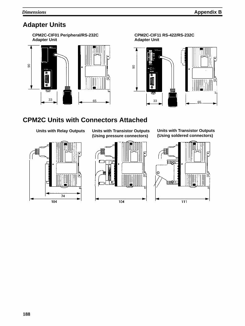
Appendix BDimensions
188
Adapter UnitsCPM2C-CIF01 Peripheral/RS-232CAdapter Unit
CPM2C-CIF11 RS-422/RS-232CAdapter Unit
90
33 65
90
33 65
CPM2C Units with Connectors Attached
Units with Relay Outputs Units with Transistor Outputs(Using pressure connectors)
Units with Transistor Outputs(Using soldered connectors)
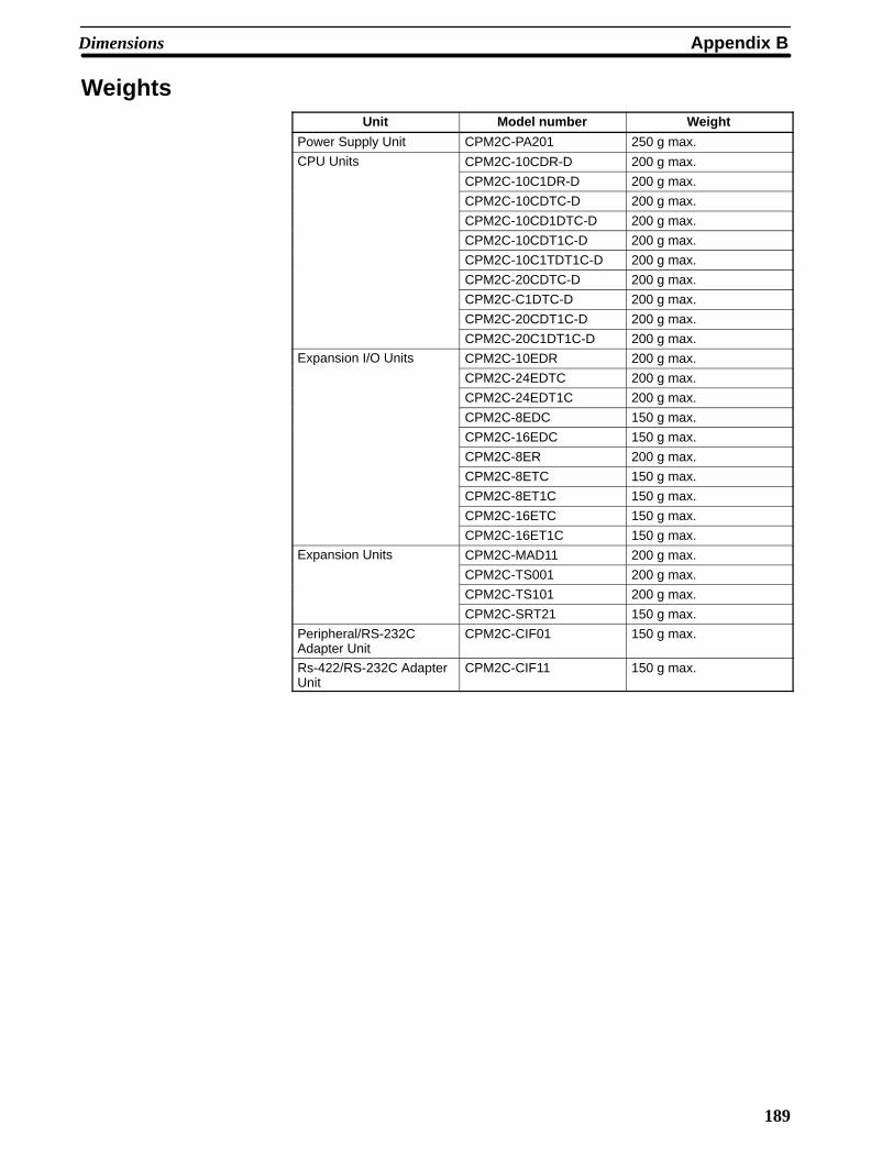
Appendix BDimensions
189
WeightsUnit Model number Weight
Power Supply Unit CPM2C-PA201 250 g max.
CPU Units CPM2C-10CDR-D 200 g max.
CPM2C-10C1DR-D 200 g max.
CPM2C-10CDTC-D 200 g max.
CPM2C-10CD1DTC-D 200 g max.
CPM2C-10CDT1C-D 200 g max.
CPM2C-10C1TDT1C-D 200 g max.
CPM2C-20CDTC-D 200 g max.
CPM2C-C1DTC-D 200 g max.
CPM2C-20CDT1C-D 200 g max.
CPM2C-20C1DT1C-D 200 g max.
Expansion I/O Units CPM2C-10EDR 200 g max.
CPM2C-24EDTC 200 g max.
CPM2C-24EDT1C 200 g max.
CPM2C-8EDC 150 g max.
CPM2C-16EDC 150 g max.
CPM2C-8ER 200 g max.
CPM2C-8ETC 150 g max.
CPM2C-8ET1C 150 g max.
CPM2C-16ETC 150 g max.
CPM2C-16ET1C 150 g max.
Expansion Units CPM2C-MAD11 200 g max.
CPM2C-TS001 200 g max.
CPM2C-TS101 200 g max.
CPM2C-SRT21 150 g max.
Peripheral/RS-232CAdapter Unit
CPM2C-CIF01 150 g max.
Rs-422/RS-232C AdapterUnit
CPM2C-CIF11 150 g max.

191
Index
Numbers1:1 connections, 100
1:N connections, 97
AAC Power Supply Unit. See Power Supply Unit
Adapter Unitsavailable models, 10, 183components, 54dimensions, 188
Adapters, available models, 183
Analog I/O UnitSee also Expansion Unitsavailable models, 181components, 51dimensions, 187
arc killer, examples, xviii
ASCII, converting displays, Programming Console, 143
atmosphere, 30
Bbasic functions, 19
battery, replacing, 167
binary data, modifying, Programming Console, 140
bit status, force-set/reset, Programming Console, 142
bits, searching, Programming Console, 130
buzzer operation, Programming Console, 124
Ccabinet
installation, precautions, 61Programming Console installation, 115
cables, available models, 181
characteristics, 30
check levels, program checks, 156
checking, program syntax, Programming Console, 132
circuit configurationinputs, 34outputs
relay, 37transistor, 38
clearing, memory areas, Programming Console, 123
clock, reading and setting the clock, 144
communicationscapabilities, 20
overview, 5errors, 155
CompoBus/S I/O Link, 100
CompoBus/S I/O Link UnitSee also Expansion Unitsavailable models, 181components, 53dimensions, 187
componentsAdapter Units, 54Analog I/O Unit, 51CompoBus/S I/O Link Unit, 53CPU Units, 40Expansion I/O Units, 45Power Supply Unit, 58Temperature Sensor Units, 52
conduit installation, 66
connectorsavailable models, 180dimensions, 188
counterschanging SV, Programming Console, 138example of inputting, 148
CPM1A, function comparison, 20
CPM2A, function comparison, 20
CPU Unitsavailable models, 7, 179components, 40cyclic operation, 14dimensions, 185general specifications, 30input specifications, 34internal structure, 11
cycle time, displaying, Programming Console, 144
cyclic operation, 14
Ddata, modifying, Programming Console, 137–138, 139, 140,
141
data link, 5, 100
date. See clock
decimal data with sign. See signed decimal data
decimal data without sign. See unsigned decimal data
dielectric strength, 30
differentiated instructions, entering, 128
dimensions, 185
DIN Track installation, 64
displaysconverting between hex and ASCII, Programming Console,
143cycle time, Programming Console, 144
downloading, programs, 175
duct installation, 65

Index
192
EEC Directives, precautions, xvi
EEPROMmounting/removing, 172specifications, 171
electrical noise, preventing, 62, 65
ERR/ALM indicatorflashing, 154lit, 155
errorscommunications, 155error processing, 151fatal, 155identifying, 153non-fatal, 154programming, 156Programming Console operations, 156reading/clearing messages, Programming Console, 124user-defined errors, 154
Expansion I/O Unitsavailable models, 9, 180components, 45connections, 62dimensions, 186general specifications, 30input specifications, 36
expansion instructions, 113reading and changing function code assignments, 125
Expansion Memory Unit, 169connections, 173
Expansion Unitsavailable models, 10, 181components, 51connections, 62dimensions, 187specifications, 30
FFAL numbers, 154
FAL(06), 154
FALS numbers, 155
FALS(07), 154
false inputs, 81
fatal errors, troubleshooting, 160
features, 2
flash memory, precautions, 152
flicker output, example, 149
force-set/resetclearing, Programming Console, 143Programming Console, 142
function codes, reading and changing expansion instructionassignments, 125
functions, 6comparison, 20
H–Ihexadecimal data, converting displays, Programming Console,
143
humidity, 30
I/O capacity, 30
I/O connectorsavailable models, 180pin allocation
CPU Units, 43Expansion I/O Units, 47
wiring, 70
I/O errors, troubleshooting, 162
I/O line noise, preventing, 65
I/O refreshing, immediate refreshing, 17
I/O terminals, allocationCPU Units, 43Expansion I/O Units, 47
immediate refreshing, 17
indicatorsCompoBus/S LED indicators, 54flashing ERR/ALM indicator, 154lit ERR/ALM indicator, 155PC status indicators, 41
inductive loads, 82, 93
initialization, time required, 13
input devices, connections, 79
input specificationsCPU Units, 34Expansion I/O Units, 36
inputs, wiring, 75configuration, 75
inrush current, 30suppressing, 93
inspections, 166
installation, 64site, selecting, 61
instructionsinserting and deleting, Programming Console, 131searching, Programming Console, 129
insulation resistance, 30
interlocks, 60
interrupt program execution, in cyclic operation, 16
Lleakage current, 81
LED indicators, 41
limit switches, preventing false inputs, 81
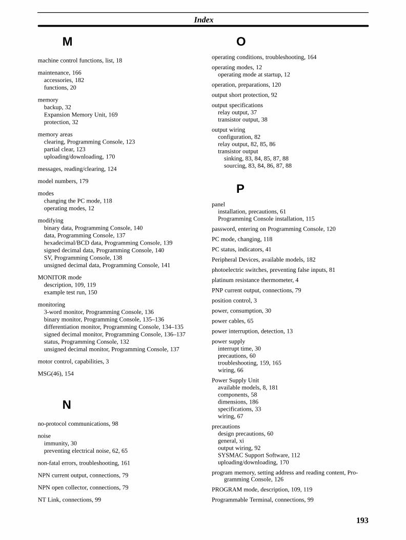
Index
193
Mmachine control functions, list, 18
maintenance, 166accessories, 182functions, 20
memorybackup, 32Expansion Memory Unit, 169protection, 32
memory areasclearing, Programming Console, 123partial clear, 123uploading/downloading, 170
messages, reading/clearing, 124
model numbers, 179
modeschanging the PC mode, 118operating modes, 12
modifyingbinary data, Programming Console, 140data, Programming Console, 137hexadecimal/BCD data, Programming Console, 139signed decimal data, Programming Console, 140SV, Programming Console, 138unsigned decimal data, Programming Console, 141
MONITOR modedescription, 109, 119example test run, 150
monitoring3-word monitor, Programming Console, 136binary monitor, Programming Console, 135–136differentiation monitor, Programming Console, 134–135signed decimal monitor, Programming Console, 136–137status, Programming Console, 132unsigned decimal monitor, Programming Console, 137
motor control, capabilities, 3
MSG(46), 154
Nno-protocol communications, 98
noiseimmunity, 30preventing electrical noise, 62, 65
non-fatal errors, troubleshooting, 161
NPN current output, connections, 79
NPN open collector, connections, 79
NT Link, connections, 99
Ooperating conditions, troubleshooting, 164
operating modes, 12operating mode at startup, 12
operation, preparations, 120
output short protection, 92
output specificationsrelay output, 37transistor output, 38
output wiringconfiguration, 82relay output, 82, 85, 86transistor output
sinking, 83, 84, 85, 87, 88sourcing, 83, 84, 86, 87, 88
Ppanel
installation, precautions, 61Programming Console installation, 115
password, entering on Programming Console, 120
PC mode, changing, 118
PC status, indicators, 41
Peripheral Devices, available models, 182
photoelectric switches, preventing false inputs, 81
platinum resistance thermometer, 4
PNP current output, connections, 79
position control, 3
power, consumption, 30
power cables, 65
power interruption, detection, 13
power supplyinterrupt time, 30precautions, 60troubleshooting, 159, 165wiring, 66
Power Supply Unitavailable models, 8, 181components, 58dimensions, 186specifications, 33wiring, 67
precautionsdesign precautions, 60general, xioutput wiring, 92SYSMAC Support Software, 112uploading/downloading, 170
program memory, setting address and reading content, Pro-gramming Console, 126
PROGRAM mode, description, 109, 119
Programmable Terminal, connections, 99
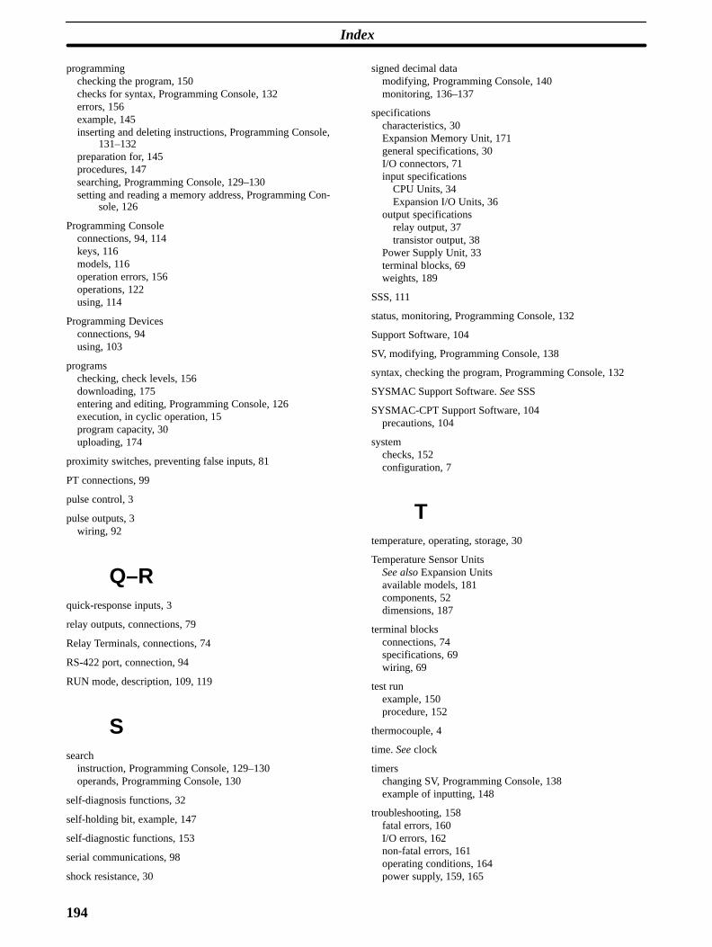
Index
194
programmingchecking the program, 150checks for syntax, Programming Console, 132errors, 156example, 145inserting and deleting instructions, Programming Console,
131–132preparation for, 145procedures, 147searching, Programming Console, 129–130setting and reading a memory address, Programming Con-
sole, 126
Programming Consoleconnections, 94, 114keys, 116models, 116operation errors, 156operations, 122using, 114
Programming Devicesconnections, 94using, 103
programschecking, check levels, 156downloading, 175entering and editing, Programming Console, 126execution, in cyclic operation, 15program capacity, 30uploading, 174
proximity switches, preventing false inputs, 81
PT connections, 99
pulse control, 3
pulse outputs, 3wiring, 92
Q–Rquick-response inputs, 3
relay outputs, connections, 79
Relay Terminals, connections, 74
RS-422 port, connection, 94
RUN mode, description, 109, 119
Ssearch
instruction, Programming Console, 129–130operands, Programming Console, 130
self-diagnosis functions, 32
self-holding bit, example, 147
self-diagnostic functions, 153
serial communications, 98
shock resistance, 30
signed decimal datamodifying, Programming Console, 140monitoring, 136–137
specificationscharacteristics, 30Expansion Memory Unit, 171general specifications, 30I/O connectors, 71input specifications
CPU Units, 34Expansion I/O Units, 36
output specificationsrelay output, 37transistor output, 38
Power Supply Unit, 33terminal blocks, 69weights, 189
SSS, 111
status, monitoring, Programming Console, 132
Support Software, 104
SV, modifying, Programming Console, 138
syntax, checking the program, Programming Console, 132
SYSMAC Support Software. See SSS
SYSMAC-CPT Support Software, 104precautions, 104
systemchecks, 152configuration, 7
Ttemperature, operating, storage, 30
Temperature Sensor UnitsSee also Expansion Unitsavailable models, 181components, 52dimensions, 187
terminal blocksconnections, 74specifications, 69wiring, 69
test runexample, 150procedure, 152
thermocouple, 4
time. See clock
timerschanging SV, Programming Console, 138example of inputting, 148
troubleshooting, 158fatal errors, 160I/O errors, 162non-fatal errors, 161operating conditions, 164power supply, 159, 165

Index
195
U–Wunsigned decimal data
modifying, Programming Console, 141monitoring, 137
uploading, programs, 174
vibration resistance, 30
voltage
operating voltage range, 30output, connections, 79supply voltage, 30
weight, 189
wiring, 65I/O connectors, 70power supply, 66terminal blocks, 69
197
Revision History
A manual revision code appears as a suffix to the catalog number on the front cover of the manual.
Cat. No. W356-E1-2
Revision code
The following table outlines the changes made to the manual during each revision. Page numbers refer to theprevious version.
Revision code Date Revised content
1 June 1999 Original production
2 January 2000 Major revisions throughout the manual. Information altered on the Analog I/OUnit, Temperature Sensor Units, the CompoBus/S I/O Link Unit, Expansion I/OUnits, Adapter Units, the AC Power Supply Unit, the Expansion Memory Unit,Relay Terminals, Terminal Blocks, and Programming Console connections.