sysda02.1 commissioning aid for digital, intelligent ac
TRANSCRIPT

SYSDA02.1Commissioning Aid for digital, intelligent
AC Drives with SERCOS interface
DOK-SUPPL*-SYSDA02.1**-AW01-EN-P • 07.99
Applications
2 8 0 9 7 8

About this documentation SYSDA02.1
DOK-SUPPL*-SYSDA02.1**-AW01-EN-P
SYSDA02.1 Commissioning Aid for digital, intelligent AC Drives withSERCOS interface
Applications
DOK-SUPPL*-SYSDA02.1**-AW01-EN-P
• SYSDA2en.doc
• Document number 120-2100-B312-01/EN
This document supports
• the installation of the commissioning aid SYSDA02.1
Document designations of previouseditions
Status Comments
DOK-SYSDA1.1-Inbetriebn.Hilfsm.-ANW-EN-P 05.93 Version 1.1
DOK-SUPPL*-SYDSA02.1**-ANW1-EN-P 07.98 Version 2.1
INDRAMAT GmbH, 1999
Copying this document, and giving it to others and the use orcommunication of the contents thereof without express authority areforbidden. Offenders are liable for the payment of damages. All rights arereserved in the event of the grant of a patent or the registration of a utilitymodel or design (DIN 34-1).
All rights are reserved with respect to the content of this documentationand the available of the product.
INDRAMAT GmbH • Bgm.-Dr.-Nebel-Str. 2 • D-97816 Lohr a. Main
Telefon 09352/40-0 • Tx 689421 • Fax 09352/40-4885
Dept. ESP (JL, RKY, TI)
This document is printed on paper bleached without the use ofchlorine.
Title
Type of documentation
Document type code
Internal file reference
The purpose of thedocumentation:
Editing sequence
Copyright
Validity
Published by
Note

SYSDA02.1 Contents I
DOK-SUPPL*-SYSDA02.1**-AW01-EN-P
Contents
1 General Informations 1-11.1 Introduction .......................................................................................................................................... 1-1
1.2 Components......................................................................................................................................... 1-1
2 Commissioning 2-12.1 Backing up parameters ........................................................................................................................ 2-1
2.2 First Steps............................................................................................................................................ 2-1
3 SercTop: User Interface for SYSDA02.1 3-13.1 General Information about SercTop..................................................................................................... 3-1
3.2 System Prerequisites ........................................................................................................................... 3-1
3.3 Installing SercTop ................................................................................................................................ 3-2
Software Installation of SercTop ................................................................................................... 3-2
Connecting the PC to the SercBox ............................................................................................... 3-3
Start SercTop ................................................................................................................................ 3-3
3.4 Functions.............................................................................................................................................. 3-3
Menu File....................................................................................................................................... 3-3
Menu Parameter ........................................................................................................................... 3-4
Menu Commissioning.................................................................................................................... 3-4
Menu View..................................................................................................................................... 3-4
Menu Extras .................................................................................................................................. 3-4
Menu Options................................................................................................................................ 3-4
Menu Help ..................................................................................................................................... 3-5
Menu Right Mouse Key................................................................................................................. 3-5
4 SercBox 4-14.1 SERCOS interface ............................................................................................................................... 4-1
4.2 Cycle Times ......................................................................................................................................... 4-1
4.3 Diagnoses and Error Display ............................................................................................................... 4-1
4.4 Communication Phases SercBox ........................................................................................................ 4-1
Commmunication Phase 0............................................................................................................ 4-1
Communication Phase 1 ............................................................................................................... 4-2
Communication Phase 2 ............................................................................................................... 4-2
Communication Phase 3 ............................................................................................................... 4-3
Communication Phase 4 ............................................................................................................... 4-3
5 Command Value Generator Functions 5-15.1 Introduction .......................................................................................................................................... 5-1

II Contents SYSDA02.1
DOK-SUPPL*-SYSDA02.1**-AW01-EN-P
General.......................................................................................................................................... 5-1
Overview ....................................................................................................................................... 5-1
5.2 Command Value Generator Torque Control........................................................................................ 5-3
Checking Encoder Polarity............................................................................................................ 5-3
5.3 Command Value Generator Velocity Control....................................................................................... 5-4
Jogging.......................................................................................................................................... 5-4
Reversing (Velocity Control).......................................................................................................... 5-5
Step Mode (Velocity Control) ........................................................................................................ 5-6
5.4 Command Value Generator Position Control....................................................................................... 5-7
Reversing (Position Control) ......................................................................................................... 5-7
Step Mode (Position Control) ........................................................................................................ 5-8
5.5 Noise Generator................................................................................................................................... 5-9
6 Diagnostics and Error Messages 6-16.1 List of Diagnostics and Error Messages .............................................................................................. 6-1
Diagnoses on the 7 Segment Display ........................................................................................... 6-1
6.2 Status Message Definitions ................................................................................................................. 6-2
Display "0" : Phase 0 or phase 0, phase changeover active......................................................... 6-2
Display "1" : Phase 1 or phase 1, phase changeover active......................................................... 6-2
Display "2" : Phase 2 or phase 2, phase changeover active......................................................... 6-2
Display "3" : Phase 3 or phase 3, phase changeover active......................................................... 6-2
Display "b" : Phase 4 "ready to operate" ....................................................................................... 6-2
Display "5." : Test mode: Zero bit stream...................................................................................... 6-2
Display "6." : Test mode: Continuous light .................................................................................... 6-2
Display "7" : Fiber optic ring not closed......................................................................................... 6-3
Display "8." : Reset........................................................................................................................ 6-3
6.3 Definition of Error Messages................................................................................................................ 6-4
Display "C" : Double AT failure...................................................................................................... 6-4
Display "d" : NC/MMI service channel HS timeout ........................................................................ 6-4
Display "E" : Changeover: Phase2 ⇒3 not possible ..................................................................... 6-5
Display "F" : Changeover: Phase 3⇒4 not possible ..................................................................... 6-5
Display "h" : Drive error ................................................................................................................. 6-5
Display "A" : Drive addresses not correct...................................................................................... 6-6
Display "L" : Fiber optic ring interrupted ........................................................................................ 6-6
Display "n" : Configuration error (command/actual value channel)............................................... 6-7
Display "o" : Error in time slot computation ................................................................................... 6-7
Display "r" : SercBox: Internal error............................................................................................... 6-8
Display "U" : Error in lifecounter .................................................................................................... 6-8
Display "u" : Copy time too long .................................................................................................... 6-9
Display "y" : Checksum error (Y parameter) ................................................................................. 6-9
Display "c" : Input signal SYNCIN failed...................................................................................... 6-10
Directory of Customer Service Locations

SYSDA02.1 General Informations 1-1
DOK-SUPPL*-SYSDA02.1**-AW01-EN-P
1 General Informations
1.1 Introduction
The commissioning aid for certified drives with SERCOS interface is usedin particular with initial startups and when servicing.
The comfortable user interface, SercTop, offers parameter administration,diagnoses and a simple test operation mode independent of a controlunit.
The equipment is suited for such tasks as single drives or complete drivepackages, whereby the number of drives in the SERCOS ring is limited to8 participants. The drives in the ring are individually set into operation;only one axis can be run.
Operating with SYSDA requires no special settings in the drive. Forexample, the same address settings are acceptable as used whenoperating with one control.
In addition to the general functions for parameter administration andservice, the user interface also offers extensive commissioning. The useris guided step by step through parametrization up to a simple test run ofthe drives.
Parameter administration offers several possibilities for filling and thedocumentation of drive parameters. Thus, for example, all the parametersof all the drives in one ring can be compiled into one backup copy. Thedata secured in this fashion can now easily be transferred to a differentdrive package.
Back-up copies are stored as ASCII files. This data format permitsprocessing any time thereafter with any editors and a simple output(monitor, printer) without having to call up the menu program.
Parameter files put together by the user (e.g., correction tables) can beimported without any additional work.
1.2 Components
Included in the delivery of the commissioning aid for certified drives withSERCOS interface are:
• 1 SercBox (SERCOS interface master) 200x110x45mm
• 1 plug-in power supply unit 100 - 240 V / 47 - 63 Hz
• 1 serial cable (l = 5m) to connect the SercBox to a PC
• 2 fibre-optics cable (l = 5m)
• 1 SercTop software
• this document

1-2 General Informations SYSDA02.1
DOK-SUPPL*-SYSDA02.1**-AW01-EN-P
Fig. 1-1: Overview: commissioning aid for digital intelligent drives
The components are connected as illustrated.
The user of SYSDA02.1 does not need extensive knowledge of SERCOSinterface specifications.
The SERCOS interface conform connection means that the modulesworks in all SERCOS interface applications.

SYSDA02.1 Commissioning 2-1
DOK-SUPPL*-SYSDA02.1**-AW01-EN-P
2 Commissioning
2.1 Backing up parameters
To enable operations with all certified drives, the SercBox automaticallyinitiates specific settings in the units. It is recommended, that the followingparmeters of all drives are secured or backed up, so that they can beloaded back into the drives once operation with the SercBox has beensuccessfully completed.
S-0-0001 NC cycle time (Tncyc)
S-0-0002 SERCOS cycle time (Tscyc)
S-0-0006 AT transmission starting time (T1)
S-0-0089 MDT transmission starting time (T2)
S-0-0008 Command valid time (T3)
S-0-0007 Feedback acquisition starting time (T4)
S-0-0009 Beginning address in master data telegram
S-0-0010 Length of master data telegram
S-0-0015 Telegram type
S-0-0032 Main operating mode
S-0-0024 Configuration list of master data telegram
S-0-0016 Configuration list of drive telegram
2.2 First Steps
The goal of this commissioning is to bring the SercBox with a SERCOSdrive into SERCOS phase 4.
The following steps must be completed to startup:
• Install SercTop as described in section 3.3 "Installing SercTop".
• Establish connection with serial cable between SercBox (connectorcode: SercTop) and your PC (connector COM1/2).
• The two fibre-optics cables must be connected from the SercBoxconnection RxD/TxD to the drive connection RxD/TxD.
• Prepare the drive for the operation with a data rate of 2MBit. Switchthe SERCOS participant address of the drive to one.
• Switch drive on.
• Switch SercBox on (the supplied plug-in power supply unit has avoltage range of 100 - 240 V ).
• Start SercTop.

2-2 Commissioning SYSDA02.1
DOK-SUPPL*-SYSDA02.1**-AW01-EN-P
Call up "system overview" under "Parameter -> System basicconfiguration" and make the following settings:
With "next" move into the next window.

SYSDA02.1 Commissioning 2-3
DOK-SUPPL*-SYSDA02.1**-AW01-EN-P
With "next" move into the next window.
Under "Parameter" select "individual parameter".
The following parameters must be set to zero:
"Lifecounter difference", Y-0-0018
"Command value generator enable", Y-0-0044
Select "Extras" under "operating mode".
SercBox commissioning is now completed.

2-4 Commissioning SYSDA02.1
DOK-SUPPL*-SYSDA02.1**-AW01-EN-P
SYSDA02.1 SercTop: User Interface for SYSDA02.1 3-1
DOK-SUPPL*-SYSDA02.1**-AW01-EN-P
3 SercTop: User Interface for SYSDA02.1
3.1 General Information about SercTop
SercTop is the comfortable user interface on SYSDA and SERCOS driveswhich can be run with MS-Windows. SercTop offers the followingfunctions from version 04VRS:
• Parametrization and commissioning of any machine that meets theinternational standard IEC 61491 of SERCOS interface.
• A highly directed commissioning of the settings on the SercBox.
• The SERCOS functions are easy to hand, e.g., phase changeovers,cyclical configurations and initial program loading.
• Function specific commissioning of drives belonging to drive firmwareFWA-DIAX03-ELS-04VRS-MS,FWA-DIAX03-ELS-05VRS-MS,FWA-DIAX04-ELS-05VRS-MS,FWA-DIAX03-SSE-01VRS-MS,FWA-DIAX03-SSE-02VRS-MS,FWA-DIAX04-SSE-02VRS-MS,FWA-DIAX03-SHS-02VRS-MS,FWA-DIAX04-SHS-02VRS-MS,andFWA-ECODRV-SSE-02VRS-MS,FWA-ECODRV-SSE-03VRS-MS,FWA-ECODR2-SSE-03VRS-MS,
• Selected parameter blocks can be loaded and stored.
• There are various diagnostics.
• A context sensitive help system (Ctrl-F1) in connection with the helpsystem drive firmeware of INDRAMAT and the help system SercBox.
• Dialogues for oscilloscope functions with time and frequency diagram.
• Dialogues for command value generator.
3.2 System Prerequisites
SercTop can be run with Windows 3.1, Windows 95 and Windows NT butrequires the following hardware:
• at least 80486 processor
• a main memory of at least 8MB
• at least 7MB of available hard drive memory
• one available RS232 interface

3-2 SercTop: User Interface for SYSDA02.1 SYSDA02.1
DOK-SUPPL*-SYSDA02.1**-AW01-EN-P
3.3 Installing SercTop
Software Installation of SercTopSercTop is supplied on 3,5“ disks. (DOS format; 1,44MB)
Note: Prior to installation, please make a backup copy of theSercTop disc. Install the software using this backup copy ofthe SercTop disc. Install the software using this backup copy.Keep the original disk in a safe place! To install the programon your PC, it is necessary to use the installation program onthe disk.
Please follow the steps below to install SercTop:
• Read this documentation in its entirety.
• Switch PC on and start Windows.
• Insert SercTop disk 1 in disk drive.
• In menu "file" select command "execute...“.
Note: If SercTop is to be installed on a PC which already has anolder version of it, then this version will be retained. Thedirectory suggested by the installation program will be list theversion number as well as the icon of the program group.If an older version is to be removed from the hard drive, thensimply erase the directy in which the relevant "SercTop.exe" islocated as well as the icon in the program group.
• In input field "command line enter:" A:\ SETUP (if SercTop disk is indrive A:).
• Now follow the instruction of the installation program.
Once installation is complete, the new SERCANS program group shouldbe on your PC. The SercTop program symbol should be in this group.

SYSDA02.1 SercTop: User Interface for SYSDA02.1 3-3
DOK-SUPPL*-SYSDA02.1**-AW01-EN-P
Connecting the PC to the SercBoxA connecting cable, SYSDA02.1, is needed for the data exchangebetween the SercBox and the PC (included in delivery).
SESAN012
SignalRxDTxD
GND
2
Pin
3
5
Signal
TxDRxD
GND
housing
9-pin D-Sub, connector
SercBox, SercTop Terminal /PC
9-pin D-Sub, bushing
RTSCTS
DSRDTR
2Pin
3
5
78
64
Fig. 3-1: Allocation of the connectors
Start SercTopPrerequisites:
SercTop has been installed successfully, SercBox is on and connected tothe PC via a serial cable.
Start SercTop in the SERCANS group in the program manager.
SercTop is started and attempts to establish a connecting structure withthe SercBox.
3.4 Functions
Menu FileThe submenus "load" and "store" are listed in the menu "file".
Submenu LoadParameters can be loaded out of a file into the drives of the SercBox.
Submenu SaveThe S/P parameters in the drives and the Y parameters of the SercBoxare stored in a file.

3-4 SercTop: User Interface for SYSDA02.1 SYSDA02.1
DOK-SUPPL*-SYSDA02.1**-AW01-EN-P
Menu ParameterThe dialog windows, run through during commissioning, are in the menuparameters as well as the dialog windows for individual parameters andthe list of all S, P and Y parameters.
List of all S, P and Y ParametersThe S/P parameters of the selcted drive are listed by name, operatingdata and unit. The user can sort per ident number or alphabetically, cansearch per ident number or text and change parameters.
List of all invalid ParametersThe invalid parameters of the SercBox or the selected drive are listed byname, operating data and unit. The user can sort alphabetically ornumerically or search for texts and change parameters.
Individual ParametersA parameter of a selected drive address is listed by name, operating data,minimum and maximum value and unit. The user can sort per identnumber or alphabetically, search per ident number or text and changeident number.
Menu CommissioningThe menu items SercBox basic configuration or parameter fixing arelocated in the menu commissioning. If these are called up, then the usermust run through a series of dialog windows for the parametrization ofaxis overlapping Y parameters or axis parameters (Y, S or P parameters).
Menu ViewIn menu view the diagnostic screen displayed in the background isswitched from installation status, drive status of a drive within a selectedinstallation status and a parameter group that the user can configure.
Menu ExtrasThis entails menu items on phase changeovers, viz., parametrizationmode, operating mode, phase changeovers and menu item diagnosiswith the submenus of the internal inputs and outputs as well as dialogwindows for additional diagnosis and startup tools, for e.g., "analogoutputs", "command value box", "oscilloscope".
Menu OptionsSuch menu items as connections, for switching online to offline, language,for switching between German, English and Japanese and for switchingto japanese codes, are located here.

SYSDA02.1 SercTop: User Interface for SYSDA02.1 3-5
DOK-SUPPL*-SYSDA02.1**-AW01-EN-P
Menu HelpWhen bringing down the submenus, all drive firmware helps and SercBoxinstalled are displayed. The user can reconfigure, using submenu"settings", the allocation of the helps to the drive firmwares as needed.
Menu Right Mouse KeyThe right mouse key (Shift-F10) can open a local menu at any point inSercTop making some help functions available (phase transitions, drivehelp, dialog (single parameter). If the current cursor position is on adisplay element of a parameter (e.g., input field), then additional info onthe parameter can be accessed and it can be accepted into a list in menu"parameter group accepted".

3-6 SercTop: User Interface for SYSDA02.1 SYSDA02.1
DOK-SUPPL*-SYSDA02.1**-AW01-EN-P

SYSDA02.1 SercBox 4-1
DOK-SUPPL*-SYSDA02.1**-AW01-EN-P
4 SercBox
4.1 SERCOS interface
SercBox is a SERCOS interface master that can support up to amaximum of eight drives. Both the communication cycle times and thedata rates can be set via the system parameter "SERCOS cycle time" and"data rate".
The SERCON410B assembly assumes the processing of SERCOSinterface communications.
As the assembly can only support the standard functions of SERCOSinterface functions it is possible to connect SERCOS compatible slaves(I/O stations and drives).
4.2 Cycle Times
SercBox makes SERCOS cycle times of 0,5 ms, 0,75 ms, 1 ms, through32 ms in increments of 0,25 ms. The following table supplies data aboutSERCOS cycle times, data rates and the number of drives in a ring.
Data rate in ring 4 drives in ring 8 drives in ring
2 Mbit/s 1 ms 2 ms
4 Mbit/s 0,5 ms 1 msTab. 4-1: Cycle times
4.3 Diagnoses and Error Display
A display module (M1) is on the SercBox. It is made up of a 7-segmentdisplay and a red LED.
The definition of the errors displayed is defined in section 6.
4.4 Communication Phases SercBox
Commmunication Phase 0Close fiber optic ring: "system status" = 0x0000
SercBox attempts to close the fiber optic ring.
• "system status" = 0xE008: fiber optic ring not closed.
• "system status" = 0xE001: fiber optic ring closed.
If the fiber optic ring is closed, then the SercBox switches intocommunication phase 1.

4-2 SercBox SYSDA02.1
DOK-SUPPL*-SYSDA02.1**-AW01-EN-P
Communication Phase 1Drive identification: "system status" = 0xE002
All drives with addresses in the system parameter "list of drive addresses"(Y-0-0012) are queried.
If all programmed drive addresses in the ring are present, then "systemstatus" is set to 0xE003 and SercBox switches into communicationsphase 2.
If SercBox detects a difference between the programmed drive addressesand those addresses on the ring, then the relevant axis structure of thediagnostic status is set to 0x8005 (see display "A", Definition of ErrorMessages, Section 6.3).
Communication Phase 2Parameterization mode: "system status" = 0xE003
In phase 2 SercBox permits the transmission of parameters via the userinterface. If the control or the user interface generates the transition ofphases 2 and 3, then SercBox conducts the following operations:
• In addition, during phase 2, the operating mode and the scalingparameters must be set in the drives for the relevant application by theuser interface.
This involves the following ident numbers:
operating modes: S-0-0032, S-0-0033, S-0-0034, S-0-0035
position scaling: S-0-0076, S-0-0077, S-0-0078, S-0-0079
velocity scaling: S-0-0044, S-0-0045, S-0-0046
torque scaling: S-0-0086, S-0-0093, S-0-0094
accel scaling: S-0-0160, S-0-0161, S-0-0162
polarity parameters: S-0-0055, S-0-0043, S-0-0085
Note: See drive handbook for instructions on programming theseparameters!
• All necessary data (identification numbers) are copied from all drivesto calculate the time slot:
S-0-0003 t1min S-0-0004 tATMT S-0-0005 t5 S-0-0087 tATAT S-0-0088 tMTSY S-0-0090 tMTSG S-0-0096 SLKN
• Both command value and actual value configuration lists are checked.
• SercBox calculates the time slot.

SYSDA02.1 SercBox 4-3
DOK-SUPPL*-SYSDA02.1**-AW01-EN-P
• The calculated communication parameters are transmitted to thedrive.S-0-0006 t1
S-0-0089 t2 S-0-0008 t3 S-0-0007 t4 S-0-0001 tNcyc S-0-0002 tScyc
• SercBox transmits the parameters for the telegram structure to thedrives (S-0-0009, S-0-0010, S-0-0015, S-0-0016, S-0-0024).
• The command "reset class 1 diagnostics" (S-0-0099) is transmitted tothe drives.
• The changeover command (S-0-0127) is transmitted to the drives.
If SercBox was able to switch into communication phase 3, then systemstatus is set to 0xE004.
If changeover phase 2 -> 3 was not possible, then the diagnostics statusis set to 0xD002 (see display "E", Definition of Error Messages, Section6.3).
Communication Phase 3Parameterization mode: "system status" = 0xE004
In phase 3 SercBox permits the transmission of parameters via the NC-/MMI service channel or user interface. If the control or user interfacegenerates the transition of phase 3 to phase 4, then SercBox conductsthe following operations:
• Changeover command (S-0-0128) is transmitted to the drives.
If SercBox was able to switch into communication phase 4, then thesystem status is set to 0xE005.
If the changeover phase 3 -> 4 was not possible, then the diagnosticsstatus is set to 0xD003 (see display "F", Definition of Error MessagesSection 6.3).
Communication Phase 4Operating mode: "system status" = 0xE005
In communication phase 4 command and actual values are valid.

4-4 SercBox SYSDA02.1
DOK-SUPPL*-SYSDA02.1**-AW01-EN-P

SYSDA02.1 Command Value Generator Functions 5-1
DOK-SUPPL*-SYSDA02.1**-AW01-EN-P
5 Command Value Generator Functions
5.1 Introduction
The command value generator is an independent function in the SercBox.SercTop is needed as a user interface.
GeneralThe command value generator is a general tool to initiate operation of thedrive without the control unit but using the SERCOS interface.
The drive receives defined command values during the drive check withcommand value generator with the help of which the electrical andmechanical features of the system can be checked.
In addition, an optimum matching of the drive to a specific application ispossible. With the help of the available command value it is, for example,possible to optimize the behavior of the drive by changing the loopparameters.
The command value generator is a test and optimization tool and should,therefore, only be used by trained personnel.
WARNING
Error in the drive control
can injury personnel and destroy mechanical parts.
⇒ It is forbidden to remain within the motional range ofthe machine.
OverviewIn operating modes "velocity loop“ and "position loop“ the command valuegenerator supports functions
• jogging,
• reversing,
• step mode.
In mode "torque loop" in drives with external measuring systems it isadditionally possible to check
• the setting of encoder polarity.
The next section outlines the automatic encoder polarity check in mode"torque loop".
The subsequent section describes the functions in mode "velocity loop".This is followed by an explanation of the functionalities of the commandvalue generator in mode "position loop". The drive-internal positioncommand value interpolation is used for mode "position loop".
Note: Mode position loop can only be used in drives with internalposition command value interpolation.

5-2 Command Value Generator Functions SYSDA02.1
DOK-SUPPL*-SYSDA02.1**-AW01-EN-P
The movement of the drives are not only effected by the command valuegenerator functions but also the marginal conditions and drive-internalfunctions.
The limit values set in the drive for the operating variables
• current
• torque or force
• velocity
are always monitored (see application description of the drives).
The monitor of the position limit values which have been set drives withan absolute position measurement must be separately activated (seeS-0-0055, bit 4, position polarity). If these limit values are exceeded, thenthe drive is braked.
If special drive firmware is used, then additional variables can play a role.These are explained, however, at the relevant point in the text.
The command value generator is set by the SercBox using parametersrelevant to its function. It is activated in the SercBox user interface"SercTop" in the window of the command value box.
Limit values
Monitoring position limit values
Drive firmware
SYSDA02.1 Command Value Generator Functions 5-3
DOK-SUPPL*-SYSDA02.1**-AW01-EN-P
5.2 Command Value Generator Torque Control
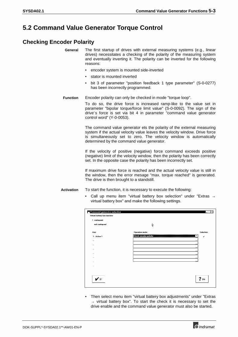
Checking Encoder PolarityThe first startup of drives with external measuring systems (e.g., lineardrives) necessitates a checking of the polarity of the measuring systemand eventually inverting it. The polarity can be inverted for the followingreasons:
• encoder system is mounted side-inverted
• stator is mounted inverted
• bit 3 of parameter "position feedback 1 type parameter" (S-0-0277)has been incorrectly programmed.
Encoder polarity can only be checked in mode "torque loop".
To do so, the drive force is increased ramp-like to the value set inparameter "bipolar torque/force limit value" (S-0-0092). The sign of thedrive‘s force is set via bit 4 in parameter "command value generatorcontrol word" (Y-0-0053).
The command value generator ets the polarity of the external measuringsystem if the actual velocity value leaves the velocity window. Drive forceis simultaneously set to zero. The velocity window is automaticallydetermined by the command value generator.
If the velocity of positive (negative) force command exceeds positive(negative) limit of the velocity window, then the polarity has been correctlyset. In the opposite case the polarity has been incorrectly set.
If maximum drive force is reached and the actual velocity value is still inthe window, then the error mesage "max. torque reached" is generated.The drive is then brought to a standstill.
To start the function, it is necessary to execute the following:
• Call up menu item "virtual battery box selection" under "Extras →virtual battery box" and make the following settings.
• Then select menu item "virtual battery box adjustments" under "Extras→ virtual battery box". To start the check it is necessary to set thedrive enable and the command value generator must also be started.
General
Function
Activation

5-4 Command Value Generator Functions SYSDA02.1
DOK-SUPPL*-SYSDA02.1**-AW01-EN-P
5.3 Command Value Generator Velocity Control
JoggingJogging an axis is only possible in "velocity control".
The drive, in this case, is given the jog velocity in steps ("command valuegenerator jogging velocity translatory", Y-0-0058 or "command valuegenerator jogging velocity rotary", Y-0-0063) as a command value. Themotional direction is set in parameter "command value generator controlword" (Y-0-0053).
The following illustrates the resulting velocity command in terms of theactivation of the jogging key.
SESAN031
Jogging + Jogging -0
1
t
t
vJogging velocity
Fig. 5-1: Jogging in velocity control
• Call up menu item "virtual battery box selection" under "Extras →virtual battery box" and make the following settings.
• Then select menu item "virtual battery box adjustments" under "Extras→ virtual battery box". To start the check it is necessary to set thedrive enable and the command value generator must also be started.
Jogging the axis is only possible as long as the drive enable is activated.If it is cleared, then the drive is shut down.
Function
Activation

SYSDA02.1 Command Value Generator Functions 5-5
DOK-SUPPL*-SYSDA02.1**-AW01-EN-P
Reversing (Velocity Control)When reversing in mode "velocity control" the drive moves, for example,with the velocity profile depicted below. The velocity command value isentered in steps. The command value generator brakes the drive oncethe actual position value has reached positions x1 or x2. After dwell time(Y-0-0057) the motional direction is reversed.
The resulting position deviation depends on the velocity set.
SESAN032
t
t
v
x
Dwell time
x1
x2
Position deviation
v1
Fig. 5-2: Reversing with velocity control
Run activation as described in "jogging".
Reversing the axis is only possible as long the drive enable is activated. Ifit is removed, then the drive brakes.
Function
Activation
5-6 Command Value Generator Functions SYSDA02.1
DOK-SUPPL*-SYSDA02.1**-AW01-EN-P
Step Mode (Velocity Control)
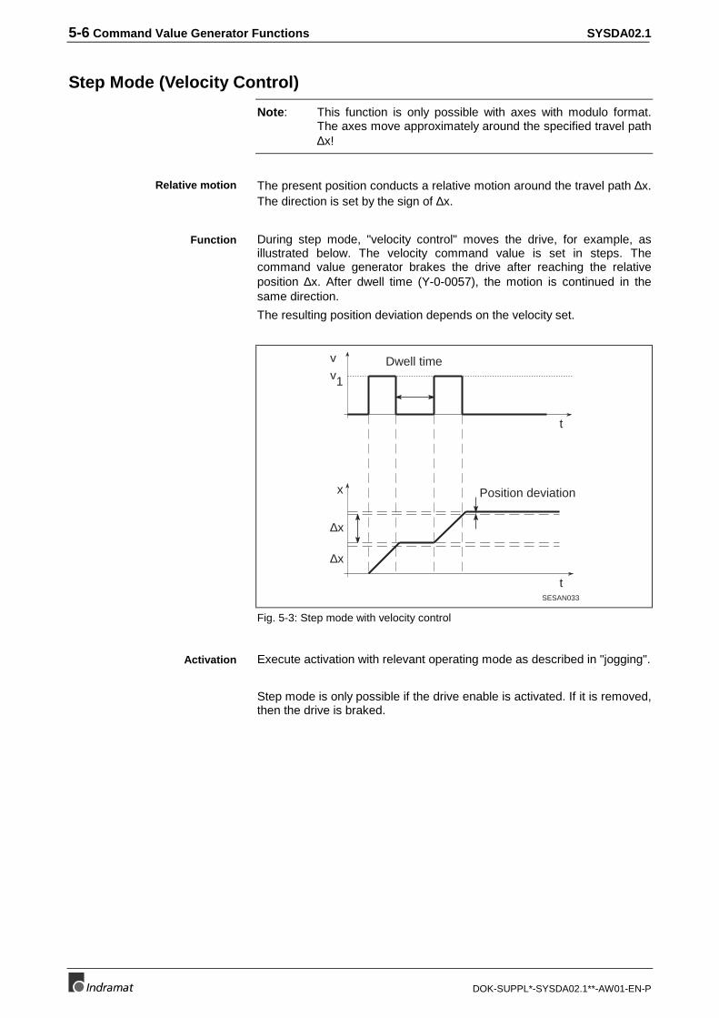
Note: This function is only possible with axes with modulo format.The axes move approximately around the specified travel path∆x!
The present position conducts a relative motion around the travel path ∆x.The direction is set by the sign of ∆x.
During step mode, "velocity control" moves the drive, for example, asillustrated below. The velocity command value is set in steps. Thecommand value generator brakes the drive after reaching the relativeposition ∆x. After dwell time (Y-0-0057), the motion is continued in thesame direction.
The resulting position deviation depends on the velocity set.
SESAN033
v1
t
t
∆x
v
x
∆x
Dwell time
Position deviation
Fig. 5-3: Step mode with velocity control
Execute activation with relevant operating mode as described in "jogging".
Step mode is only possible if the drive enable is activated. If it is removed,then the drive is braked.
Relative motion
Function
Activation

SYSDA02.1 Command Value Generator Functions 5-7
DOK-SUPPL*-SYSDA02.1**-AW01-EN-P
5.4 Command Value Generator Position Control
Reversing (Position Control)
Note: Reverse mode can only be used with drives with internalposition command interpolation.
When reversing in "position control" mode the drive moves as illustratedbelow.
SESAN034
t
t
v
x
x2
x1
Dwell time
Positioning acceleration
Positioning jerk
Positioning velocity
Actual feedback value
Fig. 5-4: Reversing with position control
The drive reverses between positions x1 and x2.
Starting with the present position, the drive accelerates to "positioningvelocity translatory" (Y-0-0069) or "positioning velocity rotary" (Y-0-0070).The rise in velocity depends on "positioning acceleration" (S-0-0260) and"positioning jerk" (S-0-0193).
The drive assumes positions x1 or x2 precisely.
Motional direction is reversed after dwell time (Y-0-0057).
Execute activation with relevant operating mode as described in "jogging".
Reversing is only possible as long as drive enable is activated. Ifremoved, the drive is braked.
Function
Activation

5-8 Command Value Generator Functions SYSDA02.1
DOK-SUPPL*-SYSDA02.1**-AW01-EN-P
Step Mode (Position Control)
Note: Step mode can only be used with drives with internal positioncommand value interpolation.
Starting with the present position, a relative motion is being conductedaround travel path ∆x. The direction is specified by the sign of ∆x.
Step mode in "position control" mode results, for example, in the followingmotion:
t
t
v
x
∆x
2∆x
Dwell time
SESAN030
Positioning velocity
Positioning jerk
Positioning velocity
Fig. 5-5: Step mode with position control
First, there is acceleration starting from the present position whilst takinginto account "positioning acceleration" (S-0-0260) and "positioning jerk"(S-0-0193) to "positioning velocity translatory" (Y-0-0069) or "positioningvelocity rotary" (Y-0-0070).
The drive runs precisely to position ∆x.
The procedure is repeated after dwell time (Y-0-0057).
Execute activation with relevant operating mode as described in "jogging".
Step mode is only possible if the drive enable is activated. If it is removed,then the drive is braked.
Relative Motion
Function
Activation

SYSDA02.1 Command Value Generator Functions 5-9
DOK-SUPPL*-SYSDA02.1**-AW01-EN-P
5.5 Noise Generator
When starting up a machine axis it is not always possible to use the jumpresponse of the velocity or position control loop to determine the system‘sfrequency. In such cases, a noise generator can be used. It makesavailable a test signal without average available.
The noise generator makes a pseudostatistic binary signal available. Itsamplitude accepts positive and negative values. The drive receives a newcommand value during each SERCOS cycle.
The amplitude of the output signal can be scaled for translatory axes viaparameter "output amplitude noise generator translatory" (Y-0-0067) orfor rotary axes via "output amplitude noise generator rotary" (Y-0-0068).
The output signal is generated repeatedly about every 0,5 minutes given aSERCOS cycle time of 2 ms. The repetition time tW of the noise generatordepends on "SERCOS cycle time" (Y-0-0004) and is computed as follows:
t tW Scyc= ⋅28
The noise signal can be switches on in any command value generatormode and is added to the relevant command value. This takes place byactivation in menu "virtual battery box".
The noise generator can be activated as long as the command valuegenerator has been started and the drive enable is set. If the drive enableis removed, then the noise generator is stopped.
General
Function
Activation

5-10 Command Value Generator Functions SYSDA02.1
DOK-SUPPL*-SYSDA02.1**-AW01-EN-P

SYSDA02.1 Diagnostics and Error Messages 6-1
DOK-SUPPL*-SYSDA02.1**-AW01-EN-P
6 Diagnostics and Error Messages
6.1 List of Diagnostics and Error Messages
Diagnoses on the 7 Segment DisplayThe following lists the diagnostics and fault messages of the 7 segmentdisplay:
M1Error inphase Reaction
Diagn.register Description
7-Seg.
Systemstatus
Status message in system parameter"system status" (Y-0-0015)
0 0 none 0xE001 phase 0
0 0 none 0xE011 phase 0, phase changeover active
1 1 none 0xE002 phase 1
1 1 none 0xE012 phase 1, phase changeover active
2 2 none 0xE003 phase 2
2 2 none 0xE013 phase 2, phase changeover active
3 3 none 0xE004 phase 3
3 3 none 0xE014 phase 3, phase changeover active
b 4 none 0xE005 phase 4: "ready"
5. 0-4 phase 0 0xE006 test mode: zero bit stream
6. 0-4 phase 0 0xE007 test mode: continuous light
7 0 none 0xE008 fiber optic ring not closed
8. - - 0x0000 reset
Diagn.Status
Error messsages in diagnostics of the drives
C 3-4 phase 0 0x8007 double AT failure
d 2-4 phase 0 0x8006 NC/MMI service channel HS timeout
E 2 phase 2 0xD002 changeover: phase 2 -> 3 not possible
F 3 phase 3 0xD003 changeover: phase 3 -> 4 not possible
h 2-4 phase 2-4 0xD001 drive error (class 1 diagnostics, S-0-0011)
Systemerror
Error messages in system parameter"system error" (Y-0-0011)
A 1 phase 0 0x8005 drive address not correct
C 3-4 phase 0 0x8007 double AT failure
L 1-4 phase 0 0x8009 fiber optic ring disrupted
n 2 phase 0 0xF001 configuration error (command/actual value channel)
o 2 phase 0 0xF002 error in time slot calculation
r 0-4 phase 0 0xF004 SercBox: internal error
U 4 phase 0 0xF005 lifecounter error
u 2 phase 0 0xF006 copy times too long
y 0 phase 0 0xF007 check sum error (Y parameter)
c 2-4 phase 0 0xF008 input signal SYNCIN failed
Tab. 6-1: Diagnoses on the 7 segment display

6-2 Diagnostics and Error Messages SYSDA02.1
DOK-SUPPL*-SYSDA02.1**-AW01-EN-P
6.2 Status Message Definitions
Display "0" : Phase 0 or phase 0, phase changeover activeSercBox sets communication phase 0.
Display "1" : Phase 1 or phase 1, phase changeover activeSercBox sets communication phase 1.
Display "2" : Phase 2 or phase 2, phase changeover activeSercBox sets communication phase 2.
Display "3" : Phase 3 or phase 3, phase changeover activeSercBox sets communication phase 3.
Display "b" : Phase 4 "ready to operate"SercBox sets communication phase 4. Power can be switched on and thedrives run.
Display "5." : Test mode: Zero bit streamThe test mode "zero bit stream“ was selected.
Reaction from the SercBoxSercBox sends a zero bit stream and prevents phase runup.
CauseTest mode activated via DIP switch SD1 switch 1.
RemedySwitch DIP switch SD1 switch 1 off.
Display "6." : Test mode: Continuous lightTest mode "Continuous light“ was selected.
Reaction from the SercBoxThe SercBox sends continuous light and prevents phase runup.
CauseTest mode activated via DIP switch SD1 switch 2.
RemedySwitch DIP switch SD1 switch 2 off.

SYSDA02.1 Diagnostics and Error Messages 6-3
DOK-SUPPL*-SYSDA02.1**-AW01-EN-P
Display "7" : Fiber optic ring not closedAfter a hardware reset from the SercBox the SERCOS ring was notclosed. The SercBox cannot receive ten sequential MST telegrams ofphase 0.
Reaction from the SercBoxThe SercBox remains in state "fiber optic ring not closed“ until the fiberoptic ring is closed. It then conducts a runup itself into target phase (seeparameter "phase initiation" Y-0-0014).
Cause
• Fiber optic cable transposed or not correctly screwed on.
• Fiber optic cable ring defective.
• Data rate of drives and the SercBox have different settings.
• The optical transmission power (for the SercBox see parameterY-0-0016) of a participant on the SERCOS ring is set too low.
• Drive defective.
Remedy
• Check all fibre-optics cables.
• Check data rates,SercBox: see parameter Y-0-0003, Drive: see applications of drive manufacturer
• Optical transmission power of all participants on SERCOS ring mustbe adjusted to the actual length.
Display "8." : ResetSercBox is in reset. Communications with SercTop not possible.
Reaction from the SercBox-
Cause
• SercBox assembly defective.
Remedy
• Contact customer service.

6-4 Diagnostics and Error Messages SYSDA02.1
DOK-SUPPL*-SYSDA02.1**-AW01-EN-P
6.3 Definition of Error Messages
Display "C" : Double AT failureThe SercBox did not receive two sequential drive telegrams (AT)from adrive.
Reaction from the SercBoxPhase regression to communication phase 0.
Cause
• Fiber optic cable not correctly screwed on.
• Fiber optic cable defective.
• Drive defective.
• The optical transmission power (for the SercBox see parameterY-0-0016) of a participant on the SERCOS ring is set too low.
Remedy
• Check all fibre-optics cables.
• Optical transmission power of all participants on SERCOS ring mustbe adjusted to the actual length.
Display "d" : NC/MMI service channel HS timeoutA drive has not toggled bit 0 in drive status (service transport handshake)with ten SERCOS cycles a result of a query via the service channel.
Reaction from the SercBoxPhase regression in communications phase 0.
Cause
• Drive defective.
Remedy
• Replace drive.
• Contact Customer Service of the drive manufacturer.

SYSDA02.1 Diagnostics and Error Messages 6-5
DOK-SUPPL*-SYSDA02.1**-AW01-EN-P
Display "E" : Changeover: Phase2 ⇒3 not possibleThe SercBox cannot progress from phase 2 to phase 3.
Reaction from the SercBoxThe SercBox retains set changeover command and ends phase runup.The diagnosis of the relevant drive is written into the diagnostics channel.
CauseAt least one drive refuses to move into phase 3.
RemedyClear error in drive affected (see help guidelines from drivemanufacturer).
Display "F" : Changeover: Phase 3⇒4 not possibleThe SercBox cannot conduct phase changeover from phase 3 to phase 4.
Reaction from the SercBoxThe SercBox retains the changeover command and ends phase runup.The diagnosis of the relevant drive is written into the diagnostics channel.
CauseAt least one drive refuses to move into phase 4.
RemedyClear errror in drive affected (see help guidelines from drivemanufacturer).
Display "h" : Drive errorA drive signals a drive error by setting the drive error bit in drive status forclass 1 diagnostics.
Reaction from the SercBoxThe diagnosis of the relevant drive is written into the diagnostics channel.
CauseAn error occured in the drive.
RemedyEvaluate parameter "class 1 diagnostics" (S-0-0011), "diagnosticmessage" S-0-0095 and "diagnostic message number" (S-0-0390) andthen eliminate the cause of the problem.
Clear error.

6-6 Diagnostics and Error Messages SYSDA02.1
DOK-SUPPL*-SYSDA02.1**-AW01-EN-P
Display "A" : Drive addresses not correctThe phase progression out of phase 0 cannot be executed because thedrive addresses entered in parameter "drive address list" (Y-0-0012)could not be found in the ring.
Reaction from the SercBoxPhase regression into communications phase 0.
Cause
• At least on drive address has been entered in Y-0-0012 which couldnot be found in the ring.
• After the SercBox detected that the fiber optic ring was closed, it wasinterrupted in phase 1 again.
Remedy
• Check drive addresses. It is allowed to have drive addresses in thering that are not entered in parameter "drive address list" (Y-0-0012).
• Check the fiber optic ring.
• Check data rates,SercBox: see parameter Y-0-0003, Drive: see application description of the drive manufacturer.
Display "L" : Fiber optic ring interruptedThe fiber optic ring was interrupted after it was recognized that it wasclosed.
Reaction from the SercBoxPhase regression to communication phase 0.
Cause
• Fiber optic ring defective.
• Data rate of drive and the SercBox have been set differently.
• The optical transmission power (for the SercBox see parameterY-0-0016) of a user on the SERCOS ring is set too low.
• Drive defective.
Remedy
• Check all fiber optic cables.
• Check data rates,SercBox: see parameter Y-0-0003, Drives: see application description of drive manufacturer.
• Optical transmission power of all users on SERCOS ring must beadjusted to the actual length.

SYSDA02.1 Diagnostics and Error Messages 6-7
DOK-SUPPL*-SYSDA02.1**-AW01-EN-P
Display "n" : Configuration error (command/actual value channel)An error occurred while configuring the cyclical telegram data with theentries from command/actual value channel.
Reaction from the SercBoxPhase regression to communications phase 0.
Cause
• Too many command or actual values have been configured.
• Bit 15 has been set in Y-0-0039 or Y-0-0040 and the length entered inlow byte is too big.
Remedy
• Reduce the amount of cyclical data (see parameter S-0-0016,S-0-0024 in the drives).
• Clear bit 15 in Y-0-0039 or Y-0-0040 or change the length of commandor actual value channel.
Display "o" : Error in time slot computationWhile computing times for SERCOS transmission phase 4, an erroroccurred.
Reaction from the SercBoxPhase regression to communication phase 0.
Cause
• The configured command or actual values are not supported by atleast one drive (see parameter Y-0-0021 - Y-0-0036) because theparameter number is not present or cannot be cyclically configured(see parameter S-0-0187, S-0-0188).
• The command value generator has been activated in the SercBox anda mode set for which the SercBox wants to automatically cyclicallyconfigure parameters that are not in the drive or cannot be cyclicallyconfigured (see parameter S-0-0187, S-0-0188). For example, somedrives do not support "drive-internal interpolation".
Remedy
• Check wether the parameters entered in relevant command and actualvalue channels are allowed by the drive for cyclical transmission (seeparameter Y-0-0021 - Y-0-0036 and parameter S-0-0187, S-0-0188).
• Command value generator must be switched off and a different modeselected.
6-8 Diagnostics and Error Messages SYSDA02.1
DOK-SUPPL*-SYSDA02.1**-AW01-EN-P
Display "r" : SercBox: Internal errorAn internal error has occurred on the SercBox.
Reaction from the SercBoxPhase regression to communication phase 0.
CauseInternal hardware test routines have not been properly completed.
Remedy
• Contact Customer Service.
Display "U" : Error in lifecounterNC and the SercBox monitor the transmission of new command andactual values in each NC cycle. The SercBox increments the "lifecounterSERCANS" (Y-0-0019) for this purpose and the NC does the same for"lifecounter NC" (Y-0-0020). The difference between the two is greaterthan allowable lifecounter difference (Y-0-0018).
Reaction from the SercBoxPhase regression to communication phase 0.
CauseThe NC is not using the "lifecounter NC" (Y-0-0020) properly.
Remedy
• Check NC program.
• If NC not connected: switch lifecounter monitoring off, to do so write 0into Y-0-0018.

SYSDA02.1 Diagnostics and Error Messages 6-9
DOK-SUPPL*-SYSDA02.1**-AW01-EN-P
Display "u" : Copy time too longThe copying of the actual values of the drive into the DPR is not yetcompleted at the time when copying of the command values from theDPR into the MDT is to start (S-0-0006 + transmission time of last AT +Y-0-0037 > S-0-0089 - Y-0-0010).
Reaction from the SercBoxPhase regression to communication phase 0.
Cause
• Too many command values configured.
• Too many actual values configured.
• SERCOS cycle time too small for the number of real-time data to betransmitted.
• "Data rate" (Y-0-0003) too small to transmit the amount of data in thecycle time.
Remedy
• Configure fewer command values
• Configure fewer actual values.
• Increase "SERCOS cycle time" (Y-0-0004).
• Increase "data rate" (Y-0-0003).
Display "y" : Checksum error (Y parameter)The SercBox checks all Y parameters for validity by means of achecksum. Each parameter that passes this check, is entered in the "listof invalid Y parameters" (Y-0-0042).
Reaction from the SercBoxCommunication phase 0 is set.
Cause
• New SercBox firmware has been installed.
• E²PROM defective.
Remedy
• Write sensible values into the parameters in "list of invalid Yparameter" (Y-0-0042).
• Contact Customer Service.

6-10 Diagnostics and Error Messages SYSDA02.1
DOK-SUPPL*-SYSDA02.1**-AW01-EN-P
Display "c" : Input signal SYNCIN failedThe exchange of real time data via the DPR between the SercBox andthe NC is synchronized by the synchronous master. If the NC is the"synchronous master" (Y-0-0002), then the SercBox supervises theSYNCIN signal with watchdog.
Reaction from the SercBoxPhase regression to communication phase 0.
CauseParameter Y-0-0002 is not zero.
RemedyParameter Y-0-0002 must be set to zero.
SYSDA02.1 Sales & Service Facilities
DOK-SUPPL*-SYSDA02.1**-AW01-EN-P
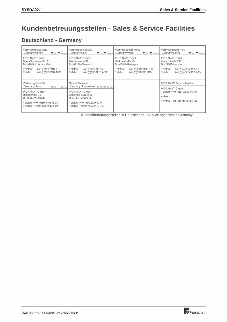
Kundenbetreuungsstellen - Sales & Service Facilities
Deutschland - Germany
Vertriebsgebiet Mitte Germany Centre V/S Service
INDRAMAT GmbHBgm.-Dr.-Nebel-Str. 2D - 97816 Lohr am Main
Telefon: +49 (0)9352/40-0Telefax: +49 (0)9352/40-4885
Vertriebsgebiet Ost Germany East V/S Service
INDRAMAT GmbHBeckerstraße 31D - 09120 Chemnitz
Telefon: +49 (0)371/35 55-0Telefax: +49 (0)371/35 55-333
Vertriebsgebiet West Germany West V/S Service
INDRAMAT GmbHHarkortstraße 25D - 40849 Ratingen
Telefon: +49 (0)2102/43 18-0Telefax: +49 (0)2102/41 315
Vertriebsgebiet Nord Germany North V/S Service
INDRAMAT GmbHKieler Straße 212D - 22525 Hamburg
Telefon: +49 (0)40/85 31 57-0Telefax: +49 (0)40/85 31 57-15
Vertriebsgebiet Süd Germany South V/S Service
INDRAMAT GmbHRidlerstraße 75D-80339 München
Telefon: +49 (0)89/540138-30Telefax: +49 (0)89/540138-10
Gebiet Südwest Germany South-West V/S Service
INDRAMAT GmbHBöblinger Straße 25D-71229 Leonberg
Telefon: +49 (0)7152/9 72-6Telefax: +49 (0)7152/9 72-727
INDRAMAT Service-Hotline
INDRAMAT GmbHTelefon: +49-(0)172/660 04 06
-oder-
Telefon: +49-(0)171/333 88 26
Kundenbetreuungsstellen in Deutschland - Service agencies in Germany
Sales & Service Facilities SYSDA02.1
DOK-SUPPL*-SYSDA02.1**-AW01-EN-P
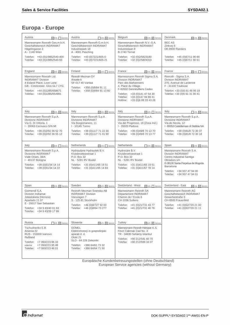
Europa - Europe
Austria V/S Service
Mannesmann Rexroth Ges.m.b.H.Geschäftsbereich INDRAMATHägelingasse 3A - 1140 Wien
Telefon: +43 (0)1/9852540-400Telefax: +43 (0)1/9852540-93
Austria V/S Service
Mannesmann Rexroth G.m.b.H.Geschäftsbereich INDRAMATIndustriepark 18A - 4061 Pasching
Telefon: +43 (0)7221/605-0Telefax: +43 (0)7221/605-21
Belgium V/S Service
Mannesmann Rexroth N.V.-S.A.Geschäftsbereich INDRAMATIndustrielaan 8B-1740 Ternat
Telefon: +32 (0)2/5823180Telefax: +32 (0)2/5824310
Denmark V/S Service
BEC ASZinkvej 6DK-8900 Randers
Telefon: +45 (0)87/11 90 60Telefax: +45 (0)87/11 90 61
England V/S Service
Mannesmann Rexroth Ltd.INDRAMAT Division4 Esland Place, Love LaneGB - Cirencester, Glos GL7 1YG
Telefon: +44 (0)1285/658671Telefax: +44 (0)1285/654991
Finland V/S Service
Rexroth Mecman OYAnsatie 6SF-017 40 Vantaa
Telefon: +358 (0)9/84 91 11Telefax: +358 (0)9/84 91 13 60
France V/S Service
Mannesmann Rexroth Sigma S.A.Division INDRAMATParc des Barbanniers4, Place du VillageF-92632 Gennevilliers Cedex
Telefon: +33 (0)141 47 54 30Telefax: +33 (0)147 94 69 41Hotline: +33 (0)6 08 33 43 28
France V/S Service
Rexroth - Sigma S.A.Division INDRAMAT270, Avenue de LardenneF - 31100 Toulouse
Telefon: +33 (0)5 61 49 95 19Telefax: +33 (0)5 61 31 00 41
Italy V/S Service
Mannesmann Rexroth S.p.A.Divisione INDRAMATVia G. Di Vittoria, 1I - 20063 Cernusco S/N.MI
Telefon: +39 (0)2/92 36 52 70Telefax: +39 (0)2/92 36 55 12
Italy V/S Service
Mannesmann Rexroth S.p.A.Divisione INDRAMATVia Borgomanero, 11I - 10145 Torino
Telefon: +39 (0)11/7 71 22 30Telefax: +39 (0)11/7 71 01 90
Italy V/S Service
Mannesmann Rexroth S.p.A.Divisione INDRAMATVia del Progresso, 16 (Zona Ind.)I - 35020 Padova
Telefon: +39 (0)49/8 70 13 70Telefax: +39 (0)49/8 70 13 77
Italy V/S Service
Mannesmann Rexroth S.p.A.Divisione INDRAMATVia de Nicola, 12I - 80053 Castellamare di Stabbia NA
Telefon: +39 (0)81/8 72 30 37Telefax: +39 (0)81/8 72 30 18
Italy V/S Service
Mannesmann Rexroth S.p.A.Divisione INDRAMATViale Oriani, 38/AI - 40137 Bologna
Telefon: +39 (0)51/34 14 14Telefax: +39 (0)51/34 14 22
Netherlands V/S Service
Hydraudyne Hydrauliek B.V.Kruisbroeksestraat 1P.O. Box 32NL - 5281 RV Boxtel
Telefon: +31 (0)411/65 19 51Telefax: +31 (0)411/65 14 83
Netherlands V/S Service
Hydrocare B.V.Kruisbroeksestraat 1P.O. Box 32NL - 5281 RV Boxtel
Telefon: +31 (0)411/65 19 51Telefax: +31 (0)411/67 78 14
Spain V/S Service
Mannesmann Rexroth S.A.Divisiòn INDRAMATCentro Industrial SantigaObradors s/nE-08130 Santa Perpetua de MogodaBarcelona
Telefon: +34 937 47 94 00Telefax: +34 937 47 94 01
Spain V/S Service
Goimendi S.A.División IndramatJolastokieta (Herrera)Apartado 11 37E - 20017 San Sebastian
Telefon: +34 9 43/40 01 63Telefax: +34 9 43/39 17 99
Sweden V/S Service
Rexroth Mecman Svenska ABINDRAMAT DivisionVaruvägen 7S - 125 81 Stockholm
Telefon: +46 (0)8/727 92 00Telefax: +46 (0)8/64 73 277
Switzerland - West V/S Service
Mannesmann Rexroth SADépartement INDRAMATChemin de l`Ecole 6CH-1036 Sullens
Telefon: +41 (0)21/731 43 77Telefax: +41 (0)21/731 46 78
Switzerland - East V/S Service
Mannesmann Rexroth AGGeschäftsbereich INDRAMATGewerbestraße 3CH-8500 Frauenfeld
Telefon: +41 (0)52/720 21 00Telefax: +41 (0)52/720 21 11
Russia V/S Service
Tschudnenko E.B.Arsenia 22RUS - 153000 IvanovoRußland
Telefon: +7 093/223 96 33oder/or +7 093/223 95 48Telefax: +7 093/223 46 01
Slowenia V/S Service
DOMELElektromotorji in gospodinjskiaparati d. d.Otoki 21SLO - 64 228 Zelezniki
Telefon: +386 64/61 73 32Telefax: +386 64/64 71 50
Turkey V/S Service
Mannesmann Rexroth Hidropar A..S.Fevzi Cakmak Cad No. 3TR - 34630 Sefaköy Istanbul
Telefon: +90 212/541 60 70Telefax: +90 212/599 34 07
Europäische Kundenbetreuungsstellen (ohne Deutschland)European Service agencies (without Germany)
SYSDA02.1 Sales & Service Facilities
DOK-SUPPL*-SYSDA02.1**-AW01-EN-P
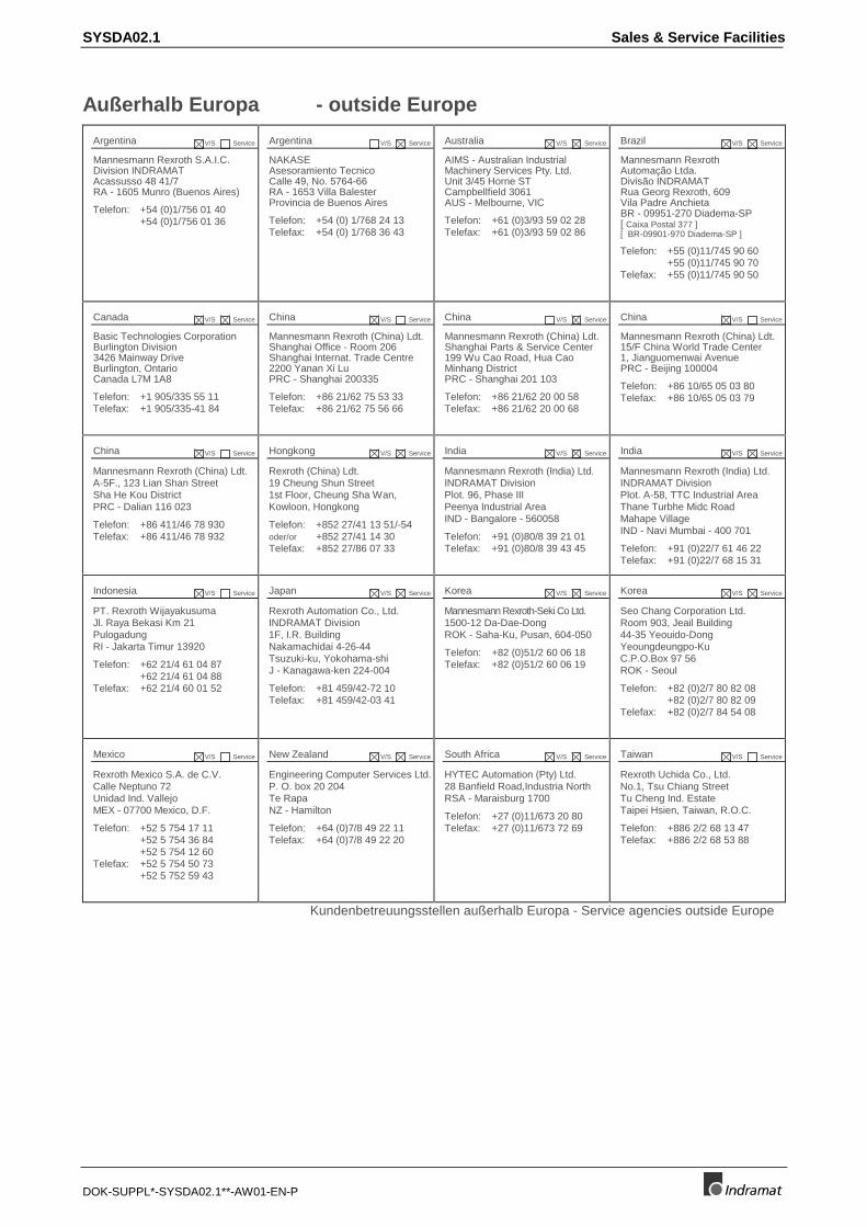
Außerhalb Europa - outside Europe
Argentina V/S Service
Mannesmann Rexroth S.A.I.C.Division INDRAMATAcassusso 48 41/7RA - 1605 Munro (Buenos Aires)
Telefon: +54 (0)1/756 01 40+54 (0)1/756 01 36
Argentina V/S Service
NAKASEAsesoramiento TecnicoCalle 49, No. 5764-66RA - 1653 Villa BalesterProvincia de Buenos Aires
Telefon: +54 (0) 1/768 24 13Telefax: +54 (0) 1/768 36 43
Australia V/S Service
AIMS - Australian IndustrialMachinery Services Pty. Ltd.Unit 3/45 Horne STCampbellfield 3061AUS - Melbourne, VIC
Telefon: +61 (0)3/93 59 02 28Telefax: +61 (0)3/93 59 02 86
Brazil V/S Service
Mannesmann RexrothAutomação Ltda.Divisão INDRAMATRua Georg Rexroth, 609Vila Padre AnchietaBR - 09951-270 Diadema-SP[ Caixa Postal 377 ][ BR-09901-970 Diadema-SP ]
Telefon: +55 (0)11/745 90 60+55 (0)11/745 90 70
Telefax: +55 (0)11/745 90 50
Canada V/S Service
Basic Technologies CorporationBurlington Division3426 Mainway DriveBurlington, OntarioCanada L7M 1A8
Telefon: +1 905/335 55 11Telefax: +1 905/335-41 84
China V/S Service
Mannesmann Rexroth (China) Ldt.Shanghai Office - Room 206Shanghai Internat. Trade Centre2200 Yanan Xi LuPRC - Shanghai 200335
Telefon: +86 21/62 75 53 33Telefax: +86 21/62 75 56 66
China V/S Service
Mannesmann Rexroth (China) Ldt.Shanghai Parts & Service Center199 Wu Cao Road, Hua CaoMinhang DistrictPRC - Shanghai 201 103
Telefon: +86 21/62 20 00 58Telefax: +86 21/62 20 00 68
China V/S Service
Mannesmann Rexroth (China) Ldt.15/F China World Trade Center1, Jianguomenwai AvenuePRC - Beijing 100004
Telefon: +86 10/65 05 03 80Telefax: +86 10/65 05 03 79
China V/S Service
Mannesmann Rexroth (China) Ldt.A-5F., 123 Lian Shan StreetSha He Kou DistrictPRC - Dalian 116 023
Telefon: +86 411/46 78 930Telefax: +86 411/46 78 932
Hongkong V/S Service
Rexroth (China) Ldt.19 Cheung Shun Street1st Floor, Cheung Sha Wan,Kowloon, Hongkong
Telefon: +852 27/41 13 51/-54oder/or +852 27/41 14 30Telefax: +852 27/86 07 33
India V/S Service
Mannesmann Rexroth (India) Ltd.INDRAMAT DivisionPlot. 96, Phase IIIPeenya Industrial AreaIND - Bangalore - 560058
Telefon: +91 (0)80/8 39 21 01Telefax: +91 (0)80/8 39 43 45
India V/S Service
Mannesmann Rexroth (India) Ltd.INDRAMAT DivisionPlot. A-58, TTC Industrial AreaThane Turbhe Midc RoadMahape VillageIND - Navi Mumbai - 400 701
Telefon: +91 (0)22/7 61 46 22Telefax: +91 (0)22/7 68 15 31
Indonesia V/S Service
PT. Rexroth WijayakusumaJl. Raya Bekasi Km 21PulogadungRI - Jakarta Timur 13920
Telefon: +62 21/4 61 04 87+62 21/4 61 04 88
Telefax: +62 21/4 60 01 52
Japan V/S Service
Rexroth Automation Co., Ltd.INDRAMAT Division1F, I.R. BuildingNakamachidai 4-26-44Tsuzuki-ku, Yokohama-shiJ - Kanagawa-ken 224-004
Telefon: +81 459/42-72 10Telefax: +81 459/42-03 41
Korea V/S Service
Mannesmann Rexroth-Seki Co Ltd.1500-12 Da-Dae-DongROK - Saha-Ku, Pusan, 604-050
Telefon: +82 (0)51/2 60 06 18Telefax: +82 (0)51/2 60 06 19
Korea V/S Service
Seo Chang Corporation Ltd.Room 903, Jeail Building44-35 Yeouido-DongYeoungdeungpo-KuC.P.O.Box 97 56ROK - Seoul
Telefon: +82 (0)2/7 80 82 08+82 (0)2/7 80 82 09
Telefax: +82 (0)2/7 84 54 08
Mexico V/S Service
Rexroth Mexico S.A. de C.V.Calle Neptuno 72Unidad Ind. VallejoMEX - 07700 Mexico, D.F.
Telefon: +52 5 754 17 11+52 5 754 36 84+52 5 754 12 60
Telefax: +52 5 754 50 73+52 5 752 59 43
New Zealand V/S Service
Engineering Computer Services Ltd.P. O. box 20 204Te RapaNZ - Hamilton
Telefon: +64 (0)7/8 49 22 11Telefax: +64 (0)7/8 49 22 20
South Africa V/S Service
HYTEC Automation (Pty) Ltd.28 Banfield Road,Industria NorthRSA - Maraisburg 1700
Telefon: +27 (0)11/673 20 80Telefax: +27 (0)11/673 72 69
Taiwan V/S Service
Rexroth Uchida Co., Ltd.No.1, Tsu Chiang StreetTu Cheng Ind. EstateTaipei Hsien, Taiwan, R.O.C.
Telefon: +886 2/2 68 13 47Telefax: +886 2/2 68 53 88
Kundenbetreuungsstellen außerhalb Europa - Service agencies outside Europe
Sales & Service Facilities SYSDA02.1
DOK-SUPPL*-SYSDA02.1**-AW01-EN-P
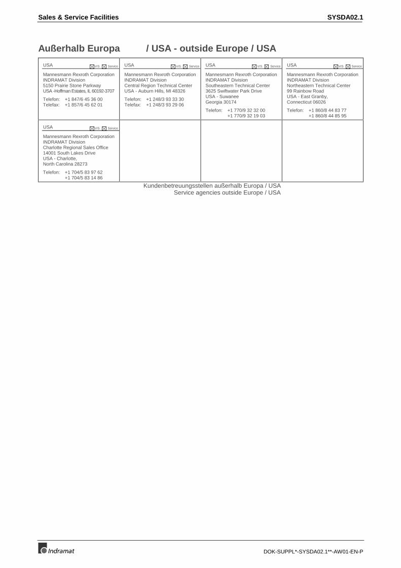
Außerhalb Europa / USA - outside Europe / USA
USA V/S Service
Mannesmann Rexroth CorporationINDRAMAT Division5150 Prairie Stone ParkwayUSA -Hoffman Estates, IL 60192-3707
Telefon: +1 847/6 45 36 00Telefax: +1 857/6 45 62 01
USA V/S Service
Mannesmann Rexroth CorporationINDRAMAT DivisionCentral Region Technical CenterUSA - Auburn Hills, MI 48326
Telefon: +1 248/3 93 33 30Telefax: +1 248/3 93 29 06
USA V/S Service
Mannesmann Rexroth CorporationINDRAMAT DivisionSoutheastern Technical Center3625 Swiftwater Park DriveUSA - SuwaneeGeorgia 30174
Telefon: +1 770/9 32 32 00+1 770/9 32 19 03
USA V/S Service
Mannesmann Rexroth CorporationINDRAMAT DivisionNortheastern Technical Center99 Rainbow RoadUSA - East Granby,Connecticut 06026
Telefon: +1 860/8 44 83 77+1 860/8 44 85 95
USA V/S Service
Mannesmann Rexroth CorporationINDRAMAT DivisionCharlotte Regional Sales Office14001 South Lakes DriveUSA - Charlotte,North Carolina 28273
Telefon: +1 704/5 83 97 62+1 704/5 83 14 86
Kundenbetreuungsstellen außerhalb Europa / USA Service agencies outside Europe / USA
SYSDA02.1
DOK-SUPPL*-SYSDA02.1**-AW01-EN-P
Notes