synthesis of resorcinol formaldehyde aerogel using uv ... · ga–a26948 synthesis of resorcinol...
TRANSCRIPT

GA–A26948
SYNTHESIS OF RESORCINOL FORMALDEHYDE AEROGEL USING UV PHOTO-INITIATORS FOR
INERTIAL CONFINEMENT FUSION EXPERIMENTS by
R.R. PAGUIO, K.M. SAITO, J.F. HUND, and R.M. JIMENEZ
NOVEMBER 2010

DISCLAIMER
This report was prepared as an account of work sponsored by an agency of the United States Government. Neither the United States Government nor any agency thereof, nor any of their employees, makes any warranty, express or implied, or assumes any legal liability or responsibility for the accuracy, completeness, or usefulness of any information, apparatus, product, or process disclosed, or represents that its use would not infringe privately owned rights. Reference herein to any specific commercial product, process, or service by trade name, trademark, manufacturer, or otherwise, does not necessarily constitute or imply its endorsement, recommendation, or favoring by the United States Government or any agency thereof. The views and opinions of authors expressed herein do not necessarily state or reflect those of the United States Government or any agency thereof.

GA–A26948
SYNTHESIS OF RESORCINOL FORMALDEHYDE AEROGEL USING UV PHOTO-INITIATORS FOR
INERTIAL CONFINEMENT FUSION EXPERIMENTS by
R.R. PAGUIO, K.M. SAITO, J.F. HUND, and R.M. JIMENEZ
This is a preprint of a paper presented at the Materials Research Society Fall Meeting in Boston, Massachusetts, November 29, Through December 3, 2010 and to be published in Proceedings.
GENERAL ATOMICS PROJECT 40011 NOVEMBER 2010


SYNTHESIS OF RESORCINOL FORMALDEHYDE AEROGEL USING UV PHOTO-INITIATORS
FOR INERTIAL CONFINEMENT FUSION EXPERIMENTS R.R. Paguio, et al.
GENERAL ATOMICS REPORT GA-A26948 1
Synthesis of Resorcinol Formaldehyde Aerogel Using UV Photo-Initiators for
Inertial Confinement Fusion Experiments
R.R. Paguio, K.M. Saito, J.F. Hund, and R.M. Jimenez
General Atomics, PO Box 85608, San Diego, California 92186-5608, U.S.A.
ABSTRACT
Resorcinol formaldehyde (R/F) aerogels have been used in a variety of laser targets for
Inertial Confinement Fusion (ICF) experiments in the form of thin films, cast shapes such as
cylinders and cubes, and hollow and solid microspheres. Besides ICF experiments, R/F aerogel
can be used for capacitors, batteries, thermal insulation, absorption/filtration media, and
chromatographic packing applications. Traditionally, R/F aerogel is synthesized using a 2-step
(base/acid catalysis) polycondensation reaction. We have developed a novel process to
synthesize the R/F aerogel using free radical UV initiator at room temperature in 10 minutes
using a UV light source. This paper will review this process , which was developed to
synthesize R/F aerogels using UV-free radical initiators. Scanning electron microscopy results
will also be discussed to show that the aerogel pore structure is similar to traditional R/F
aerogels. Fabrication of solid and hollow microspheres for ICF experiments using this R/F
aerogel synthesis technique and the technique’s limitations will also be discussed.
INTRODUCTION
Resorcinol formaldehyde (R/F) aerogel is a low-density solid-state material derived from a
gelation and liquid extraction process. This material can be used for capacitors, batteries,
thermal insulation, absorption/filtration media, and chromatographic packing applications [1].
R/F aerogels have also been used in a variety of laser targets for Inertial Confinement Fusion
(ICF) experiments in the form of thin films, cast shapes such as cylinders and cubes, and hollow
and solid microspheres. Traditionally, these R/F aerogels are synthesized using a 2-step
(base/acid catalysis) polycondensation reaction developed by Pekala et al. [2]. One of the main
uses and designs for R/F in ICF experiments is in the form of hollow microspheres (shells) for
future direct and indirect drive targets at the National Ignition Facility (NIF) and the High
Average Power Laser (HAPL) programs pilot Inertial Fusion Energy (IFE) power plant [3,4].
These R/F foam shells are a scaled-up version of foam cryogenic targets currently used at the
OMEGA facility at the University of Rochester Laboratory for Laser Energetics (LLE).
Depending on the experimental design these spheres can have a diameter that can range from
900 to 4500 μm. A picture showing the variety of R/F shell sizes and the design that they are
used for is shown in figure 1. One of the issues with the R/F aerogel shells has been the yield
that meets the wall uniformity specification. Ongoing investigations and process improvements
at General Atomics (GA) have been made to the traditional R/F shell fabrication process that was
first developed by Lambert et al. [5] to improve the yield of intact shells to 90% [6] and the
shells that meet the wall uniformity specification to 50% [7,8]. Though this yield may be
acceptable for near term experiments, this yield is not acceptable for the HAPL energy plant
design that would require a million shells a day.

SYNTHESIS OF RESORCINOL FORMALDEHYDE AEROGEL USING UV PHOTO-INITIATORS
R.R. Paguio, et al. FOR INERTIAL CONFINEMENT FUSION EXPERIMENTS
GENERAL ATOMICS REPORT GA-A26948 2
Figure 1. Shows the size difference between a variety of size ranges of R/F shells that can be
fabricated. This can range from OMEGA (900 μm) to NIF (1500-3000 μm) to HAPL scale
(4500 μm) R/F foam shell.
The wall uniformity issue has led to the investigation of alternative methods such as
dielectrophoresis (DEP) [9,10] to center and fabricate these R/F shells. DEP uses electric fields
to move and center the shell while it is in its double emulsion form. The University of Rochester
(U of R) has developed a 20 MHz device and technique that uses DEP to center a double
emulsion of water-oil-water [11,12]. The work done by Bei, et al. provided the parameters or
requirements for the aerogel precursor solution that would allow it to work in the device [11,12].
One of these parameters is that the conductivity of the aerogel precursor solution needs to be in
the 10-3
S/m range or lower, the other requirement is that the precursor solution must gel at room
temperature (RT) in 20 minutes or less. The reason why the shells must be cured at RT without
heat is because heating the DEP system can disrupt the electric field as well as damage the
circuits used to create the electric field. Heat can also cause convection currents in the DEP
centering device, which can cause the double emulsion to become unstable and can result in the
shell not centering. Based on these requirements our traditional R/F formulation used to
fabricate shells cannot be used by the U of R DEP device due to its high conductivity (5x10⁻²
S/m) and gelation time at RT (6-8 hours). This issue led to the investigation of modifying the R/F
formulation to fit these parameters. This paper will discuss these modifications, which includes
the use of UV free radical initiators to create a novel technique to synthesize the R/F aerogel.
Characterization of the pore structure of these photo-initiated R/F aerogels will also be discussed
to show that the aerogel pore structure is similar to traditional R/F aerogels.
EXPERIMENT
The R/F aerogel first developed by Pekala, et al., is synthesized by using a two-step
(base/acid catalysis) polycondensation reaction [2]. We will refer to this as the traditional
formulation since it is the current formulation that is used to synthesize R/F aerogels. The
traditional method begins with a precursor solution; the solution starts off with a base catalysis
reaction using resorcinol, formaldehyde, water and a base (0.58 M sodium bicarbonate), which
creates the hydroxymethyl aggregates, these aggregates react with one another to form the
primary particle. These particles then go through an acid catalysis step (0.01 M benzoic acid),
which brings these particles together by forming methylene ether bridges to form a hydrogel.
Controlling solvent and precursor quantities can control the density of the aerogel; the target
density for these experiments is 100 mg/cc. After curing the hydrogel, the gel is then solvent
exchanged into isopropanol to remove any water in the porous gel network and supercritically

SYNTHESIS OF RESORCINOL FORMALDEHYDE AEROGEL USING UV PHOTO-INITIATORS
FOR INERTIAL CONFINEMENT FUSION EXPERIMENTS R.R. Paguio, et al.
GENERAL ATOMICS REPORT GA-A26948 3
dried using a supercritical CO2 drier to prevent shrinkage and cracking, preserving the low
density structure of the resulting aerogel.
Before modifying the traditional reaction, conductivity measurements were taken of each
component in the formulation using a conductivity meter. Conductivity of the precursor solution
is critical for the solution to center using the DEP device because it determines the necessary
frequency required by DEP to center the wall material of the spherical droplet. The current
device developed at U of R has a maximum frequency of 20 MHz, which will work on solutions
that have a conductivity reading in the range of 10-3
S/m or less. A solution with a conductivity
that is higher than this will not work on this device.
Modifications to the traditional formula were done in two ways, the first (Modification 1)
was done by replacing the acid catalyst with a UV-free radical photo-initiator, the second
modification (Modification 2) was to replacing both the acid and base catalyst with the a UV-
free radical photo-initiator. Initiators screened for this work was two types of bisacylphosphine oxide (BAPO) under the trade name Irgacure 819 & 819DW (Ciba/BASF). Irgacure 819DW is a
dispersion of BAPO in water while Irgacure 819 BAPO in a powder form. The structure of this
BAPO initiator is shown in figure 2. To test if the solution would gel, a droplet of the precursor
solution was placed into a vial filled with mineral oil and sorbitan monooleate (Span 80). A
small amount of tetrachloroethylene (TCE) was added to keep the droplet suspended. The
droplet was then exposed at RT to UV light using a Green Spot point source unit (American
Ultraviolet); this unit uses a super-pressure 100-watt mercury lamp with peak intensity at
365 nm. If the solution gelled, the droplet now in a form of a solid hydrogel sphere or bead is
then solvent exchanged with isopropyl alcohol (IPA) and dried using a supercritical CO2 dryer.
An illustration of the vial test process is shown in figure 3. Since the traditional method is driven
by pH, the pH of the bulk solution was also monitored using a pH meter and was compared to
the pH of an R/F precursor solution made using the traditional method. The aerogel was then
measured for density gravimetrically and analyzed for its pore structure using a scanning
electron microscope (SEM) and energy dispersive x-ray analysis (EDX), EDX was used to
determine if the UV photo-initiators caused the R/F aerogel composition of carbon, hydrogen
and oxygen to change.
Figure 2. Chemical structure of the bisacylphosphine oxide (BAPO), which has the trade name
Irgacure 819 (Ciba/BASF). This is the UV free-radical initiator that was used in these
experiments.
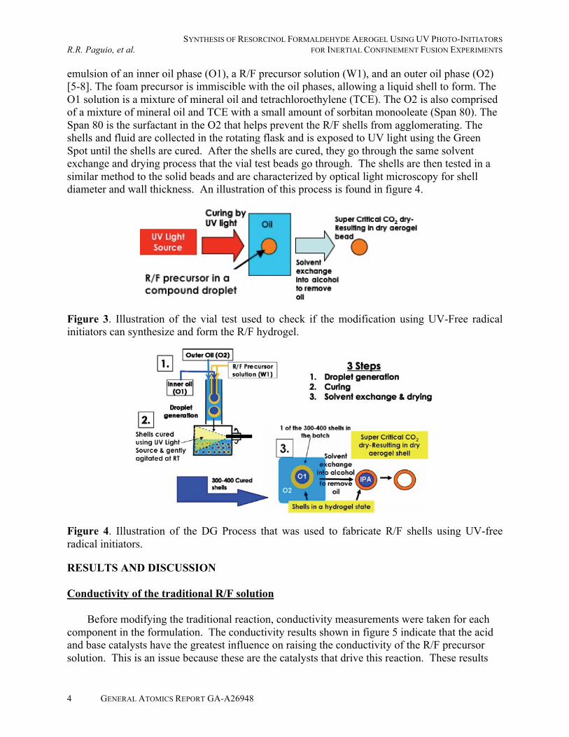
If the modification produced a gel, the precursor solution was used to fabricate shells using
our triple orifice droplet generator (DG) [5-8]. The DG method allows precise control of shell
diameters and wall thickness, so that a large quantity of similar shells of a specified size can be
made. This is similar to the methods described in reference 8; however, the only difference is
that the shells are cured at RT using a UV light source. In this process, the DG creates a double
SYNTHESIS OF RESORCINOL FORMALDEHYDE AEROGEL USING UV PHOTO-INITIATORS
R.R. Paguio, et al. FOR INERTIAL CONFINEMENT FUSION EXPERIMENTS
GENERAL ATOMICS REPORT GA-A26948 4
emulsion of an inner oil phase (O1), a R/F precursor solution (W1), and an outer oil phase (O2)
[5-8]. The foam precursor is immiscible with the oil phases, allowing a liquid shell to form. The
O1 solution is a mixture of mineral oil and tetrachloroethylene (TCE). The O2 is also comprised
of a mixture of mineral oil and TCE with a small amount of sorbitan monooleate (Span 80). The
Span 80 is the surfactant in the O2 that helps prevent the R/F shells from agglomerating. The
shells and fluid are collected in the rotating flask and is exposed to UV light using the Green
Spot until the shells are cured. After the shells are cured, they go through the same solvent
exchange and drying process that the vial test beads go through. The shells are then tested in a
similar method to the solid beads and are characterized by optical light microscopy for shell
diameter and wall thickness. An illustration of this process is found in figure 4.
Figure 3. Illustration of the vial test used to check if the modification using UV-Free radical
initiators can synthesize and form the R/F hydrogel.
Figure 4. Illustration of the DG Process that was used to fabricate R/F shells using UV-free
radical initiators.
RESULTS AND DISCUSSION
Conductivity of the traditional R/F solution
Before modifying the traditional reaction, conductivity measurements were taken for each
component in the formulation. The conductivity results shown in figure 5 indicate that the acid
and base catalysts have the greatest influence on raising the conductivity of the R/F precursor
solution. This is an issue because these are the catalysts that drive this reaction. These results

SYNTHESIS OF RESORCINOL FORMALDEHYDE AEROGEL USING UV PHOTO-INITIATORS
FOR INERTIAL CONFINEMENT FUSION EXPERIMENTS R.R. Paguio, et al.
GENERAL ATOMICS REPORT GA-A26948 5
prompted us to explore other types of ways to synthesize R/F, which led to the investigation of
using UV, free-radical initiators to replace the current catalyst. One issue with using a UV free-
radical photo-initiated system is that it can only be used to gel or polymerize in the form of a thin
film, but this works for our situation since our shells are a thin film in a spherical shape.
Figure 5. Conductivity results for each component of the traditional R/F formulation show that
the acid and base catalysis are the components that increase the conductivity of the precursor
solution.
Although the R/F precursor is a water based solution and most UV free-radical photo-
initiators are not water soluble, we identified one that was semi water soluble, Irgagcure 819DW,
which was stated earlier as a dispersion of BAPO in water. Irgacure 819DW is a white milky
liquid; we also examined regular Irgacure 819 which is in a BAPO in a solid powder form. In
screening the initiators we added 0.10 wt% of the initiator to water. Neither initiator dissolved
into water. Irgacure 819DW turned into small and large white droplets in the precursor solution
which stayed at the bottom of the solution. The Irgacure 819 was dispersed in small particles due
to its powder form. Over time the particles do sink, but if left suspended it is more evenly
dispersed in the solution. The water/Irgacure 819 solution was then exposed to UV light using
the Green Spot and the initiator particles dissolved in the water. As a result of this, Irgacure 819
was chosen as the initiator to use for these experiments.
Replacing the acid catalyst with photo-initiator
The first modification (Modification 1) was to begin with the traditional base catalysis step;
this would start off the reaction and create the hydroxymethyl aggregates, which react with one
another to form the primary particles to set up the hydrogel. After this step, 0.10 wt% of the
initiator (Irgacure 819) was added to the precursor sol and mixed to suspend or dissolve the
photoinitiator. To conduct the vial test, the precursor solution was added in the form of a
compound droplet in a vial containing mineral oil and TCE. The results of the vial test show that
the droplet of the Modification 1 solution when exposed by UV light activates the initiator to
bring these primary particles together to form a hydrogel in 5 minutes. The hydrogel was then
solvent exchanged and dried using a CPD. SEM images taken at 50,000 and 20,000X in figure 6
show that the pore structure is similar to R/F synthesized by the traditional method. The EDX
analysis of the surface of the aerogel showed that the aerogel is still made up of carbon,
hydrogen and oxygen. The density was also measured gravimetrically and is as calculated at
100 mg/cc. Optical images in figure 7 show that the surface has a rough skin, which could be
an issue with the surface of the foam. Conductivity was also analyzed and the conductivity
(3.3x10⁻²
S/m) was still too high for the DEP device due to the carbonate in the precursor

SYNTHESIS OF RESORCINOL FORMALDEHYDE AEROGEL USING UV PHOTO-INITIATORS
R.R. Paguio, et al. FOR INERTIAL CONFINEMENT FUSION EXPERIMENTS
GENERAL ATOMICS REPORT GA-A26948 6
solution. Despite the conductivity this showed that UV-free radical photoinitiators could be used
to replace the acid catalyst and still form a R/F aerogel.
Figure 6. SEM images at 50,000 and 20,000X of traditional R/F, R/F made with replacing the
acid catalyst with Photo-initiator (Modification 1) & R/F made with only UV initiator
(Modification 2). Pore structure for all three look very similar with a pore size of less than
0.10 μm.
Figure 7. Optical Image of a R/F aerogel bead fabricated by the vial test using Modification 1
(base/photo int.). The aerogel has a skin on the surface of the bead.
Because the modification formed a gel, it was then used to form shells in the DG. With the
proper density matching Modification 1 R/F shells were successfully fabricated with a diameter
of 2 mm and a shells wall of 100 μm. Because shells were successfully fabricated this solution
could still be used to fabricate shells despite not meeting the DEP requirements. Having the
shells cure at RT has provided an advantage to the current DG process because we no longer
have to density mismatch at a an elevated temperature of 70 °C which is more challenging. In
addition, the faster cure time can be an advantage for production purposes. A summary of these
modification experiments that displays the gelation time, conductivity and its pH change during
the gelation process and how it compares to the traditional process is shown in figure 8.
The shells and beads fabricated on the DG showed little to no skin on the surface in contrast
to the beads fabricated with the vial test (figure 9). This might suggest that the skin may be due
to the way the shells and beads were exposed to the light, the DG shells are rotated and more

SYNTHESIS OF RESORCINOL FORMALDEHYDE AEROGEL USING UV PHOTO-INITIATORS
FOR INERTIAL CONFINEMENT FUSION EXPERIMENTS R.R. Paguio, et al.
GENERAL ATOMICS REPORT GA-A26948 7
evenly exposed than the bead exposed in the vial test. SEM images of the pore structure of shells
produced with the DG are also similar to the aerogels fabricated using the vial test and the
traditional R/F. Density and EDX data were similar to the R/F bead fabricated with the vial test.
The pH of the R/F solution was also monitored; the results show that once the photoinitiator is
added and activated with this modification that the pH changes from 5 to 3. This suggests that
an acid began forming once the free radicals were initiated by the reaction with water, or the
hydroxyl groups on the primary particles. From this, one may suggest that the same reaction
pathway is occurring for both processes driven by the changing of the pH. However, because the
solution gels from a water-like liquid to a gel at RT much faster than the traditional method,
which takes 20 minutes at 70°C, this suggests that something else is driving the reaction besides
the formation of an acid.
Figure 8. Summary chart of the modifications that were investigated in finding a formula that
would work in the DEP centering device, and to test if UV free radical initiators can be used to
synthesize R/F aerogels.
Figure 9. Summary chart of the modifications that were investigated in finding a formula that
would work in the DEP centering device, and to test if UV free radical initiators can be used to
synthesize R/F aerogels.
Because the conductivity for Modification 1 was too high due to the carbonate in the
precursor solution, the carbonate was reduced in the solution so that the conductivity would be
low enough to use in the DEP device. We will refer to this as Modification 1-low carbonate.
In this modification the carbonate was reduced by 87%, which reduced the conductivity to
4.8x10⁻³
S/m, which satisfies the DEP centering device requirement. The solution was tested for
gelation using the vial test and the compound droplet gelled in 10 minutes at RT, which satisfies
the gelation requirement. By satisfying these two requirements, this modification is a candidate
for the DEP device. Similar to Modification 1, a skin is observed on the aerogel’s surface. One
issue is that the pore structure is larger than our standard R/F aerogel. Large pore R/F aerogels
are also observed in the traditional process when the carbonate is reduced [13,14]. A SEM
image shown in figure 10 shows these large pores and the skin that forms on the surface of the

SYNTHESIS OF RESORCINOL FORMALDEHYDE AEROGEL USING UV PHOTO-INITIATORS
R.R. Paguio, et al. FOR INERTIAL CONFINEMENT FUSION EXPERIMENTS
GENERAL ATOMICS REPORT GA-A26948 8
aerogel. Because large pore R/F can create issues in holding the fusion fuel for these
experiments, it was not used to create a shell in the DG. But it can be used as a candidate for the
DEP centering device as a proof of principle experiment.
Replacing the base and acid catalyst with photo-initiator
In Modification 2 both the base and acid catalyst were replaced with UV-free radical photo-
initiator (Irgacure 819). The hope was to treat this still as a two step process in that a photo-
initiator would be used like the base catalyst to form the hydroxymethyl aggregates which react
with one another to form the primary particles. This would be followed with more initiators to
bring these primary particles together to form the gel. In the first step the photo-initiator
(0.10 wt%) did not fully dissolve into the sol when exposed to the UV light as the first
modification. Because of this we added acetonitrile to the precursor solution to help dissolve the
photo-initiator. The solution was then exposed with UV light for 15 minutes, the sol turned into
a dark orange solution, without the acetonitrile the solution did not turn dark orange. The dark
orange color is similar to the solution color of the traditional R/F solution, which suggests that
the primary particles are forming. The pH of the solution at this stage went from 6 to 5. After
this step, more initiator (0.10 wt%) was added to help bring these primary particles together to
form the gel. The vial test results from Modification 2 gelled in 10 minutes at RT. The solution
in the curing step also changed in pH from 5 to 3, similar to Modification 1. The measured
conductivity of this R/F solution without the carbonate or acid was also measured to be an order
of magnitude lower at 3.3x10⁻³
S/m, which meets the conductivity specification to be used in the
DEP centering device. The gelation time of 10 minutes at RT also satisfies the second
requirement for the DEP device, which makes this a candidate formulation.
Like the first modification the SEM images (figure 10) show that the pore structure is
similar to the traditional R/F. Gravimetric density, EDX results are similar to Modification 1.
Like the beads fabricated using Modification 1, the beads still have a skin on the surface; optical
images are shown in figure 11(a). This solution was also used in the DG process but the
acetonitrile in the precursor solution made the emulsion unstable causing the uncured shell to
collapse into a bead before the shells cured. Like the first modification the beads that survived
the DG process had little to no skin [figure 11(b)] when compared to the beads fabricated using
the vial test. Despite these results, this shows the proof of principle that the R/F aerogel can be
synthesized using only UV free radical initiators.
Figure 10. SEM Image of R/F aerogel fabricated using Modification1-low carbonate. Lowering
the carbonate increases the pore size of the aerogel. This is also seen in the traditional process.

SYNTHESIS OF RESORCINOL FORMALDEHYDE AEROGEL USING UV PHOTO-INITIATORS
FOR INERTIAL CONFINEMENT FUSION EXPERIMENTS R.R. Paguio, et al.
GENERAL ATOMICS REPORT GA-A26948 9
Figure 11. (a) Optical images of R/F aerogel beads made with the vial test using Modification 2
(UV int. only). Skin can be found on the surface of the bead. (b) Optical image of an R/F
aerogel bead made with the DG using Modification 2 (UV int. only). Little to no skin can be
found on the surface of the bead when compared to the vial test.
Limitations
One limitation in using a UV free radical initiator is that it will only work for thin films and
small areas and can not work for high aspect ratio parts or pieces. This creates a limit on what
we can use this R/F aerogel for, which are for thin films and hollow or solid micro spheres. The
thickest film that was successfully fabricated was a 1 mm thick film that was roughly 3X3 mm in
area. Thicker films were not attempted but will be investigated in future experiments.
CONCLUSION
These experiments helped produce a new novel technique synthesize R/F aerogel using UV-
free radical initiators. These aerogels have a similar pore structure to the traditional R/F aerogel
and can be cured at RT using a UV light source faster than the traditional method at RT and at
70°C. This was done by modifying the traditional formulation by either replacing the acid
catalyst, or replacing both the acid and base catalyst. This work also produced formulations that
are suitable to be used in the DEP centering device developed by U of R to center R/F shells, and
these formulations also have the potential to be used in the traditional DG method to fabricate
shells. Future work will include testing the potential formulations on the DEP centering device,
improving the all UV photo-initator formulation to survive the DG process and optimizing the
formulation and DG process for both modifications.
REFERENCES
1. R.B. Durairaj, “Resorcinol: Chemistry, Technology & Applications,” Springer, Germany,
(2005).
2. R.W. Pekala, et al., J. Mater. Sci. 24, 3221 (1989).
3. J.D. Sethian, et al., Nucl. Fusion 43, 1693 (2003).
4. J. Perkins, et al., HAPL Program Website:
http://aries.ucsd.edu/HAPL/DOCS/HAPLtargetSpecs.doc
5. S.M. Lambert, et al., J. Appl. Polym. Sci. 65, 2111 (1997).
6. A. Nikroo, et al., Fusion Sci. Technol. 45, 84 (2004).
7. R.R. Paguio, et al., Fusion Sci. Technol. 51, 682 (2007).

SYNTHESIS OF RESORCINOL FORMALDEHYDE AEROGEL USING UV PHOTO-INITIATORS
R.R. Paguio, et al. FOR INERTIAL CONFINEMENT FUSION EXPERIMENTS
GENERAL ATOMICS REPORT GA-A26948 10
8. R.R. Paguio, et al., accepted for publication in Fusion Sci. Technol. (2010).
9. H. Pohl, Dielectrophoresis: The Behavior of Neutral Matter in Nonuniform Electric Fields,
Cambridge University Press, Cambridge (1978).
10. T. Jones, Electromechanics of Particles, Cambridge University press, New York (1995).
11. Z.-M. Bei, et al., Applied Physics Lett. 93, 184101 (2008).
12. Z.-M. Bei, et al., J. of Electrostatics 67, 173, (2009).
13. D.W. Schafer, et al., J. Non-Crst. Solids 186, 159 (1995).
14. C.A. Frederick, et al., Fusion Sci. Technol. 49, 657 (2006).